
Operating Instructions Setup Guide - Firmware Download Center
Upload
truongkhanhCategory
view
221download
0
Setup and Operating Manual
Patent 6,743,187
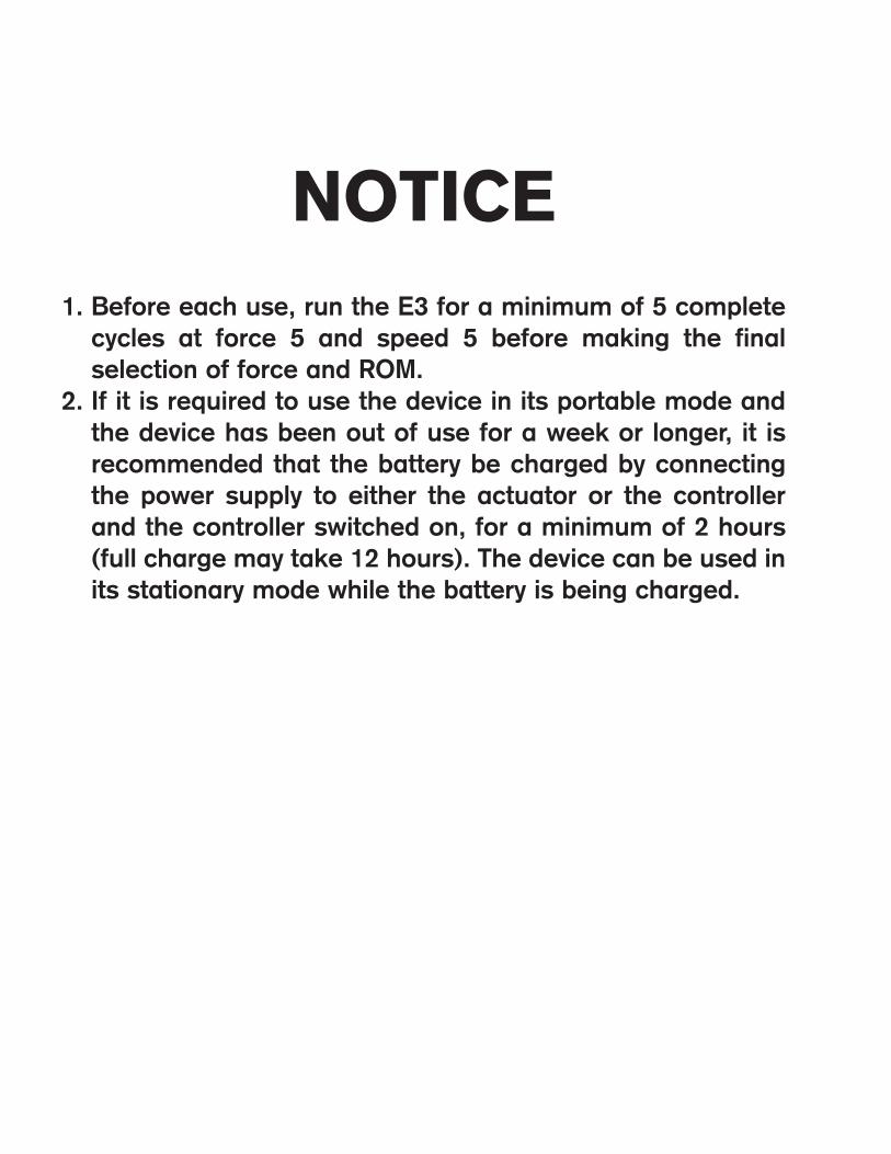
NOTICE1. Before each use, run the E3 for a minimum of 5 complete
cycles at force 5 and speed 5 before making the final selection of force and ROM.
2. If it is required to use the device in its portable mode and the device has been out of use for a week or longer, it is recommended that the battery be charged by connecting the power supply to either the actuator or the controller and the controller switched on, for a minimum of 2 hours (full charge may take 12 hours). The device can be used in its stationary mode while the battery is being charged.
E3 CPM Device Setup and Operating Manual
1
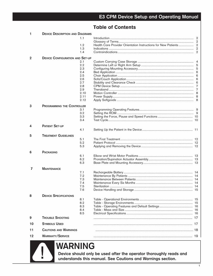
Table of Contents1 DeviceDescriptionanDDiagrams
1.1 Introduction................................................................................................ 2 GlossaryofTerms...................................................................................... 2 1.2 HealthCareProviderOrientationInstructionsforNewPatients................. 2 1.3 Indications................................................................................................. 2 1.4 Contraindications....................................................................................... 2
2 DeviceconfigurationanDset-up 2.1 CustomCarryingCaseStorage................................................................ 4 2.2 DetermineLeftorRightArmSetup............................................................ 5 2.3 ConfiguringMountingAccessory................................................................ 5 2.4 BedApplication......................................................................................... 6 2.5 ChairApplication....................................................................................... 6 2.6 Sofa/CouchApplication............................................................................. 6 2.7 StabilityandClearanceCheck.................................................................. 6 2.8 CPMDeviceSetup.................................................................................... 7 2.9 Theraband................................................................................................. 7 2.10 MotionController....................................................................................... 8 2.11 PowerSupply............................................................................................. 8 2.12 ApplySoftgoods........................................................................................ 8
3 programmingthecontroller 3.1 ProgrammingOperatingFeatures.............................................................. 9 3.2 SettingtheROM........................................................................................ 9 3.3 SettingtheForce,PauseandSpeedFunctions........................................ 10 3.4 TestCycle................................................................................................. 10
4 patientset-up 4.1 SettingUpthePatientintheDevice.......................................................... 11
5 treatmentguiDelines 5.1 TheFirstTreatment................................................................................... 12 5.2 PatientProtocol........................................................................................ 12 5.3 ApplyingandRemovingtheDevice........................................................... 12
6 packaging 6.1 ElbowandWristMotorPositions.............................................................. 13 6.2 Pronation/SupinationActuatorAssembly................................................... 13 6.3 BasePlateandMountingAccessory......................................................... 13
7 maintenance 7.1 RechargeableBattery............................................................................... 14 7.2 MaintenanceByPatients.......................................................................... 14 7.3 MaintenanceBetweenPatients................................................................. 14 7.4 MaintenanceEverySixMonths................................................................. 14 7.5 Sterilization............................................................................................... 14 7.6 DeviceHandlingandStorage................................................................... 15
8 Devicespecifications 8.1 Table-OperationalEnvironments............................................................. 15 8.2 Table-StorageEnvironments................................................................... 15 8.3 Table-OperatingFeaturesandDefaultSettings...................................... 16 8.4 Table-MassandSize.............................................................................. 16 8.5 ElectricalSpecifications............................................................................ 169 troubleshooting ...................................................................................................... 1710 symbolsuseD ...................................................................................................... 1711 cautionsanDWarnings ..................................................................................................... 1812 Warranty/service ...................................................................................................... 19
WARNINGDevice should only be used after the operator thoroughly reads and understands this manual. See Cautions and Warnings section.
E3 CPM Device Setup and Operating Manual
2
1DeviceDescriptionanDDiagrams
1.1 Introduction
The E3 Elbow CPM device is prescribed and used under the supervision of a physician or other licensed healthcare provider.
This manual has been written for the owners and operators of the device. It contains general instructions on the operation, precautionary practice and maintenance of the device. To maximize the use, efficiency and life of your E3 Elbow device, please read this manual thoroughly and become familiar with the controls and accessories before operating the device.
1.2 Health Care Provider Orientation Instructions for New Patients
• Before any setup begins, establish communication with the patient, family, etc.
• Introduce yourself.
• Explain why you are there and what you will be doing.
• Explain the purpose and function of the device and demonstrate its use. Outline the patient safety features and refer to the cautions and warnings in Section 11.
• Explain what the patient should expect when the device is turned on and how to contact their local representative for customer service.
1.3 Indications
Post-operative management of:
• Joint arthroplasty.
• Stable fractures of radius, ulna, humerus.
• Reconstructive surgery on bone, cartilage, tendons and ligaments.
• Prolonged joint immobilization.
1.4 Contraindications
Do not use the device if any of the following are present:
• Untreated or uncontrolled infection.
• Unstable fractures.
• Hemorrhage.
Note: Upon using the device, if signs of infection such as hyperthermia, fever, redness, irritation, warmth, swelling, bleeding, and/or increased persistent pain are present, discontinue operation of the device and contact the patient’s physician. Do not proceed with treatment until the physician has approved continued use of the device.
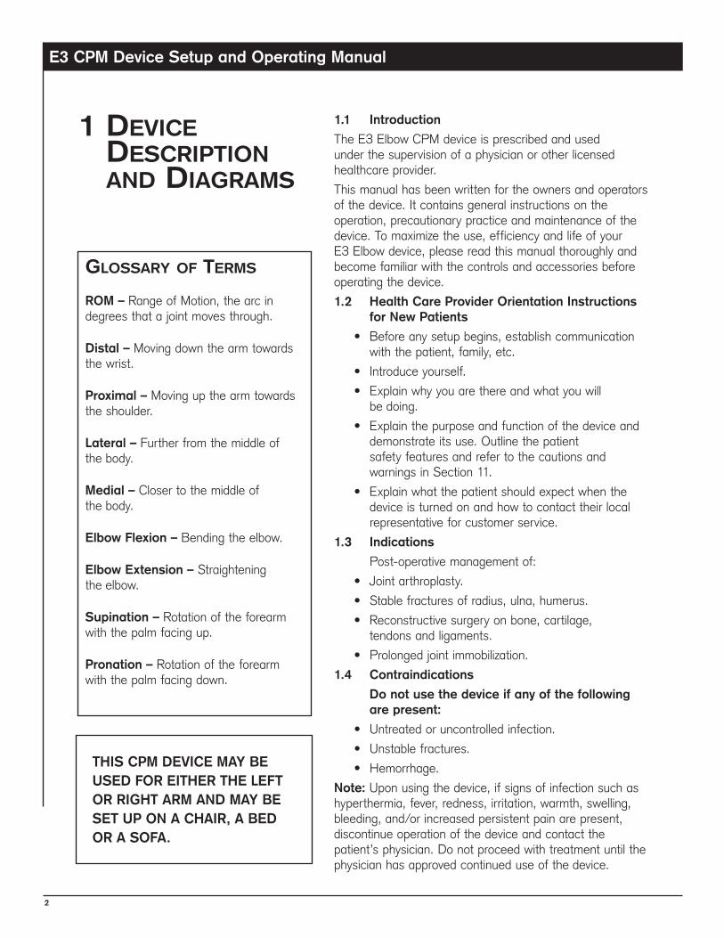
glossaryofterms
ROM – Range of Motion, the arc in degrees that a joint moves through.
Distal – Moving down the arm towards the wrist.
Proximal – Moving up the arm towards the shoulder.
Lateral – Further from the middle of the body.
Medial – Closer to the middle of the body.
Elbow Flexion – Bending the elbow.
Elbow Extension – Straightening the elbow.
Supination – Rotation of the forearm with the palm facing up.
Pronation – Rotation of the forearm with the palm facing down.
THIS CPM DEVICE MAY BE USED FOR EITHER THE LEFT OR RIGHT ARM AND MAY BE SET UP ON A CHAIR, A BED OR A SOFA.
E3 CPM Device Setup and Operating Manual
3
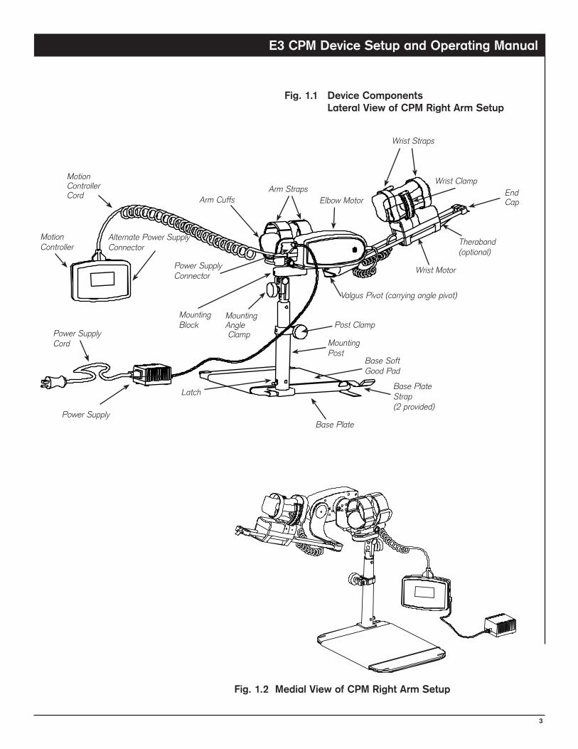
Fig. 1.1 Device Components Lateral View of CPM Right Arm Setup
Mounting Post
Base Plate
Arm Straps
Motion Controller
Base Soft Good Pad
Latch
Post ClampMounting Angle Clamp
Elbow Motor
Wrist Motor
Motion Controller Cord
Power Supply
Wrist Straps
Valgus Pivot (carrying angle pivot)
Wrist Clamp
Arm Cuffs
Mounting Block
Power Supply Cord
Base Plate Strap(2 provided)
Theraband(optional)
End Cap
Fig. 1.2 Medial View of CPM Right Arm Setup
Power Supply Connector
Alternate Power Supply Connector
E3 CPM Device Setup and Operating Manual
4
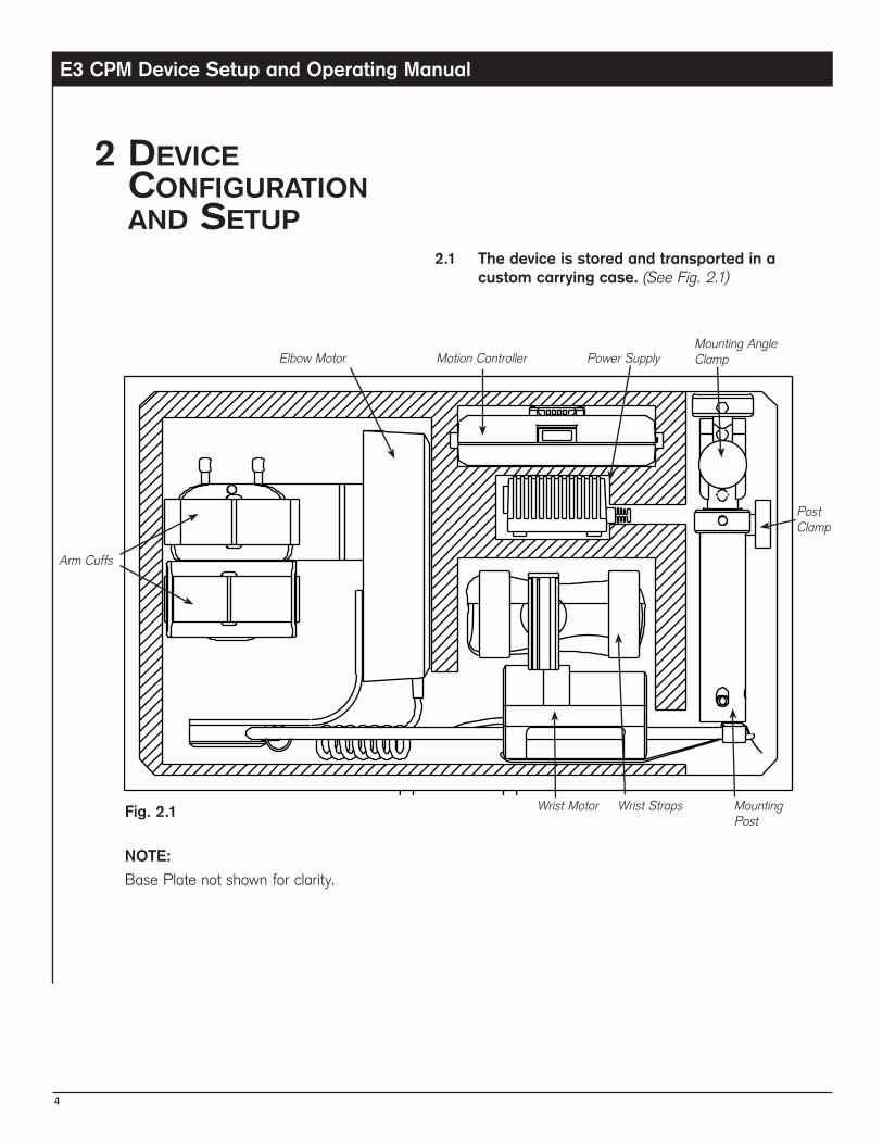
2.1 The device is stored and transported in a custom carrying case. (See Fig. 2.1)
2DeviceconfigurationanDsetup
Power SupplyMotion ControllerElbow Motor
Wrist Motor Wrist Straps
Arm Cuffs
Fig. 2.1
Mounting Angle Clamp
Mounting Post
NOTE:
Base Plate not shown for clarity.
Post Clamp
E3 CPM Device Setup and Operating Manual
5
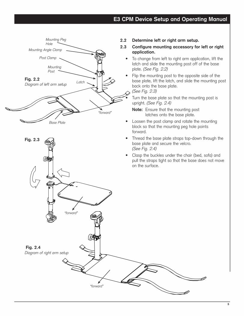
2.2 Determine left or right arm setup.
2.3 Configure mounting accessory for left or right application.
• To change from left to right arm application, lift the latch and slide the mounting post off of the base plate. (See Fig. 2.2)
• Flip the mounting post to the opposite side of the base plate, lift the latch, and slide the mounting post back onto the base plate. (See Fig. 2.3)
• Turn the base plate so that the mounting post is upright. (See Fig. 2.4)
Note: Ensure that the mounting post latches onto the base plate.
• Loosen the post clamp and rotate the mounting block so that the mounting peg hole points forward.
• Thread the base plate straps top-down through the base plate and secure the velcro. (See Fig. 2.4)
• Clasp the buckles under the chair (bed, sofa) and pull the straps tight so that the base does not move on the surface.
Latch
Mounting Angle Clamp
“forward”
Fig. 2.2
Diagram of right arm setupFig. 2.4
Diagram of left arm setup
Mounting Peg Hole
Mounting Post
Base Plate
Fig. 2.3
“forward”
“forward”
Post Clamp
E3 CPM Device Setup and Operating Manual
�
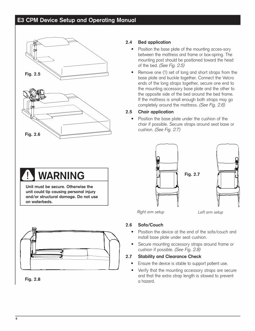
2.4 Bed application
• Position the base plate of the mounting acces-sory between the mattress and frame or box-spring. The mounting post should be positioned toward the head of the bed. (See Fig. 2.5)
• Remove one (1) set of long and short straps from the base plate and buckle together. Connect the Velcro ends of the long straps together, secure one end to the mounting accessory base plate and the other to the opposite side of the bed around the bed frame. If the mattress is small enough both straps may go completely around the mattress. (See Fig. 2.6)
2.5 Chair application
• Position the base plate under the cushion of the chair if possible. Secure straps around seat base or cushion. (See Fig. 2.7)
2.� Sofa/Couch
• Position the device at the end of the sofa/couch and install base plate under seat cushion.
• Secure mounting accessory straps around frame or cushion if possible. (See Fig. 2.8)
2.7 Stability and Clearance Check
• Ensure the device is stable to support patient use.
• Verify that the mounting accessory straps are secure and that the extra strap length is stowed to prevent a hazard.
WARNINGUnit must be secure. Otherwise the unit could tip causing personal injury and/or structural damage. Do not use on waterbeds.
Left arm setupRight arm setup
Fig. 2.5
Fig. 2.�
Fig. 2.7
Fig. 2.8
E3 CPM Device Setup and Operating Manual
7
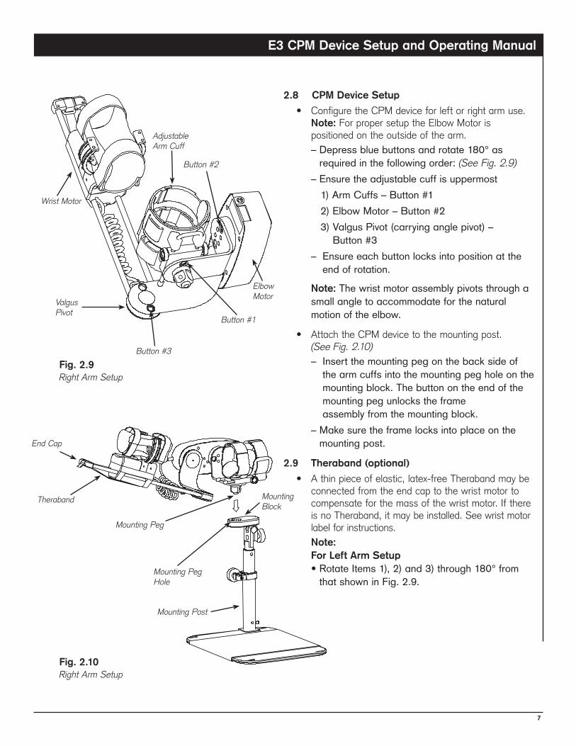
2.8 CPM Device Setup
• Configure the CPM device for left or right arm use. Note: For proper setup the Elbow Motor is positioned on the outside of the arm.
–Depressbluebuttonsandrotate180°asrequiredinthefollowingorder:(See Fig. 2.9)
–Ensuretheadjustablecuffisuppermost 1)ArmCuffs–Button#1 2)ElbowMotor–Button#2 3)ValgusPivot(carryinganglepivot)–
Button#3 –Ensureeachbuttonlocksintopositionatthe
endofrotation.
Note:Thewristmotorassemblypivotsthroughasmallangletoaccommodateforthenaturalmotionoftheelbow.
• Attach the CPM device to the mounting post. (See Fig. 2.10)
–Insertthemountingpegonthebacksideofthearmcuffsintothemountingpegholeonthemountingblock.Thebuttonontheendofthemountingpegunlockstheframeassemblyfromthemountingblock.
–Makesuretheframelocksintoplaceonthemountingpost.
2.9 Theraband (optional)
• A thin piece of elastic, latex-free Theraband may be connected from the end cap to the wrist motor to compensate for the mass of the wrist motor. If there is no Theraband, it may be installed. See wrist motor label for instructions.
Note: For Left Arm Setup •RotateItems1),2)and3)through180°from
thatshowninFig.2.9.
Button #3
Button #1
Button #2
Mounting Block
Mounting Peg Hole
Mounting Peg
Fig. 2.9 Right Arm Setup
Fig. 2.10 Right Arm Setup
Mounting Post
Theraband
End Cap
Wrist Motor
Adjustable Arm Cuff
Valgus Pivot
Elbow Motor
E3 CPM Device Setup and Operating Manual
8
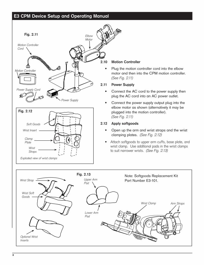
2.10 Motion Controller
• PlugthemotioncontrollercordintotheelbowmotorandthenintotheCPMmotioncontroller.(See Fig. 2.11)
2.11 Power Supply
• ConnecttheACcordtothepowersupplythenplugtheACcordintoanACpoweroutlet.
• Connectthepowersupplyoutputplugintotheelbowmotorasshown(alternativelyitmaybepluggedintothemotioncontroller).(See Fig. 2.11)
2.12 Apply softgoods
• Openupthearmandwriststrapsandthewristclampingplates.(See Fig. 2.12)
• Attach softgoods to upper arm cuffs, base plate, and wrist clamp. Use additional pads in the wrist clamps to suit narrower wrists. (See Fig. 2.13)
Note:SoftgoodsReplacementKit PartNumberE3-101.Wrist Strap
Wrist Soft Goods
Optional Wrist Inserts
Wrist Clamp
Soft Goods
Clamp Plate
Wrist Insert
Exploded view of wrist clamps
Fig. 2.12
Fig. 2.13
Wrist Straps
Fig. 2.11
Power Supply
Motion Controller Cord
ElbowMotor
Motion Controller
Power Supply Cord
Upper Arm Pad
Lower Arm Pad
Arm Straps
E3 CPM Device Setup and Operating Manual
9
3programmingthemotioncontroller
Note: See back of Motion Controller for programming summary.
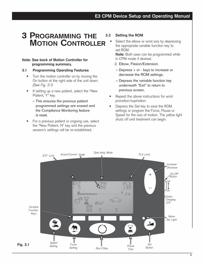
3.1 Programming Operating Features
• Turn the motion controller on by moving the On button at the right side of the unit down. (See Fig. 3.1)
• If setting up a new patient, select the “New Patient, Y” key.
–ThisensuresthepreviouspatientprogrammedsettingsareerasedandtheComplianceMonitoringfeatureisreset.
• For a previous patient or ongoing use, select the “New Patient, N” key and the previous session’s settings will be re-established.
3.2 Setting the ROM
• Select the elbow or wrist axis by depressing the appropriate variable function key to set ROM. Note: Both axes can be programmed while in CPM mode if desired.i)Elbow,Flexion/Extension.–Depress+or-keystoincreaseor
decreasetheROMsettings.–Depressthevariablefunctionkey
underneath“Exit”toreturntopreviousscreen.
• Repeat the above instructions for wrist pronation/supination.
• Depress the Set key to save the ROM settings or program the Force, Pause or Speed for the axis of motion. The yellow light shuts off and treatment can begin.
Fig. 3.1
E3 CPM Device Setup and Operating Manual
10
3.3 Setting the Force, Pause and Speed Functions.
• Stop the unit by depressing the Start/Stop key.
• Depress the Set key (a yellow light illuminates to indicate the key has been depressed).
• Select the desired function to be set (Force, Speed or Pause keys).
• Adjust the function by depressing the + or - keys to increase or decrease.
• Press “Exit” and repeat setting for each function.
• Depress the Set key (the light will go off) to store the settings and go to run mode. You will be prompted for “select mode”, “sync”, “ser” for synchronous or serial mode; press appropriate variable function key.
3.4 Test Cycle: Do NOT Skip This Procedure
• Before placing the patient in the device, press the yellow start button to run the device through a complete cycle to ensure the operational settings are correct.
• Explain to the patient what the device is doing throughout the test cycle.
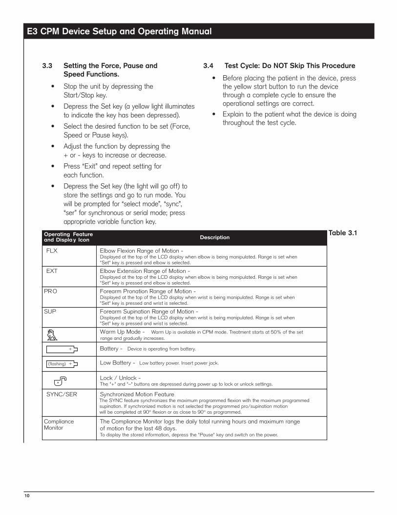
Table 3.1

E3 CPM Device Setup and Operating Manual
11
4patientsetup
4.1 Setting Up the Patient in the Device
Do this only after completion of the Test Cycle.
• Raise or lower the CPM device by supporting the device and then loosening the post clamp on the mounting post to adjust for patient’s comfort. (See Fig. 1.1)
• Positionthepatient’sarminthedevice,aligningthelateralbonyprominenceoftheelbowwiththeelbowmotoraxisofrotation.Thepatient’sshouldersshouldbelevel.(See Fig. 4.1)
• Adjust the position of the upper arm cuff by turning the silver and brass knobs on the back of the cuff to loosen and permit sliding the cuff up or down the arm. Re-tighten the knobs.
• Adjust and fasten the straps on the arm cuffs.
• Align the center of the wrist clamp approximately 1˝ (25 mm) proximal to the wrist crease and tighten the clamp knobs. (See Fig. 4.2)
• Ensure the forearm is centered in the pronation/supination drive ring and fasten the velcro straps.
Alignment
Alignment
Fig. 4.1
Fig. 4.2
Axis of Rotation
Clamp Knobs
E3 CPM Device Setup and Operating Manual
12
5treatmentguiDelines
5.1 The First Treatment
• Start treatment by depressing the Start/Stop key at the center of the motion controller unit.
• Observe the patient for 2-3 cycles to verify for comfort and alignment. See contraindications under Section 1.4.
5.2 Patient Protocol
• Describe the physician prescribed protocol to the patient.
• If the patient is required to adjust the device during the prescribed protocol, instruct the patient on the features to be adjusted.
• Have the patient repeat the instructions and adjust the device accordingly.
• Note: If the patient is at risk of injury by incorrectly adjusting the device or is not allowed to adjust the settings, lock the programmed settings on the motion controller or discontinue use and contact the patient’s physician.
5.3 Applying and Removing the Device
• Describe to the patient how to enter and exit the device.
• Describe the alignment landmarks of the elbow and wrist clamp and how they should align with rotation axes.
• Demonstrate how to secure the arm and wrist straps and clamping mechanisms and remind the patient of the danger of using the device in improper alignment.
E3 CPM Device Setup and Operating Manual
13
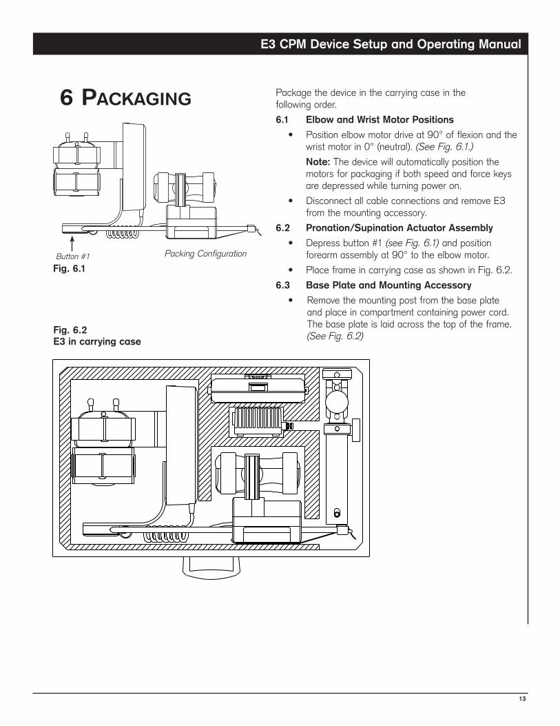
6packaging Package the device in the carrying case in the following order.
�.1 Elbow and Wrist Motor Positions
• Position elbow motor drive at 90° of flexion and the wrist motor in 0° (neutral). (See Fig. 6.1.)
Note: The device will automatically position the motors for packaging if both speed and force keys are depressed while turning power on.
• Disconnect all cable connections and remove E3 from the mounting accessory.
�.2 Pronation/Supination Actuator Assembly
• Depress button #1 (see Fig. 6.1) and position forearm assembly at 90° to the elbow motor.
• Place frame in carrying case as shown in Fig. 6.2.
�.3 Base Plate and Mounting Accessory
• Remove the mounting post from the base plate and place in compartment containing power cord. The base plate is laid across the top of the frame. (See Fig. 6.2)
Packing ConfigurationButton #1
Fig. �.1
Fig. �.2E3 in carrying case
E3 CPM Device Setup and Operating Manual
14
7.1 Rechargeable Battery
• The motion controller is equipped with a rechargeable battery which provides backup power during power outages, or patient transport. (typical duration 1 hr)
• The battery requires 10-12 hours to charge fully, if completely discharged. The battery recharges whenever the controller On/Off button is set to “On”, and the device’s power supply is connected to either the controller or to the elbow motor power connector.
• If the unit has been out of service for lengthy periods, it is recommended to charge the battery as above, with the machine plugged in, turned on, but not running.
• Battery charging status is indicated by the green light emitting diode (LED) located just below the motion controller power switch. A flashing LED indicates normal charging.
7.2 Maintenance by Patients
• Patients are responsible for using the device according to the Operating Instructions. Do not wash softgoods.
7.3 Maintenance Between Patients
• Softgoods for the device are for single patient use only.
• Check the entire unit for any visible evidence of damage, such as bent components, cracked or broken covers, frayed or damaged wires, etc. If any signs of damage are found, the unit must be repaired before use.
• Ensure that all knobs and/or levers are usable and in place.
• Ensure that all moving components move freely as required.
• Check all displays and electronic controls for proper operation.
• Check all mechanical pivot and linkage points for smooth operation and secure mechanical connection. Make sure all screws, nuts, bolts, rivets, pivot pins, and other fasteners are secure.
• Gently wipe clean all exposed surfaces with a soft cloth dampened with a mild soap solution or alcohol. Wipe soap deposits from the equipment using a clean damp cloth. For stubborn areas, use a household spray cleaner applied to a soft cloth. After cleaning, wipe off residue immediately with a water-dampened cloth. Do not use abrasive cleansers. To disinfect, wipe all exposed surfaces with a 10% solution of bleach and water, or other suitable disinfectants. Do not pour cleaning solution directly onto the machine. This may allow fluids to enter the machine and cause electrical problems, or wash lubricants away from running components reducing the life span of the device. NEVER IMMERSE THE DEVICE IN FLUIDS
• Ensure that all labels are present.
• Replace the patient softgoods kit.
• Verify that the device operates to its set limits over several complete cycles.
• For Range Of Motion (ROM) settings verify device calibration by observing the ROM of the device while taking a visual reading using a goniometer at the device’s anatomic pivot points.
7.4 Maintenance Every Six Months
• Repeat steps under 7.3 "Maintenance Between Patients".
7.5 Sterilization
• This device does not require sterilization for use.
• Exposing the device to sterilization conditions will damage the device and may result in a potential hazard.
7maintenance
E3 CPM Device Setup and Operating Manual
15
7.� Device Handling and Storage
• Do not submerse the device or any of its components in any liquid.
• Do not store the device or any of its components in a vehicle in extremely cold or hot conditions. The temperature inside a vehicle in extreme climates can exceed the recommended operating and storage temperature ranges.
• Do not sterilize the device or any of its components.
• Do not bend, twist or drop the device or controller. These actions may damage the electronics and/or device structural components.
• It is recommended that the unit be stored in the carrying case provided with the device. The carrying case is designed to protect the unit when not in use.
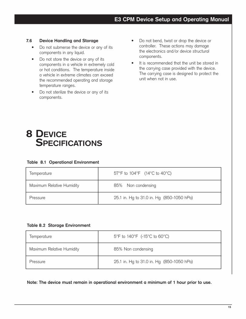
Table 8.1 Operational Environment
Temperature 57°F to 104°F (14°C to 40°C)
Maximum Relative Humidity 85% Non condensing
Pressure 25.1 in. Hg to 31.0 in. Hg (850-1050 hPa)
Table 8.2 Storage Environment
Temperature 5°F to 140°F (-15°C to 60°C)
Maximum Relative Humidity 85% Non condensing
Pressure 25.1 in. Hg to 31.0 in. Hg (850-1050 hPa)
Note: The device must remain in operational environment a minimum of 1 hour prior to use.
8Devicespecifications
E3 CPM Device Setup and Operating Manual
1�
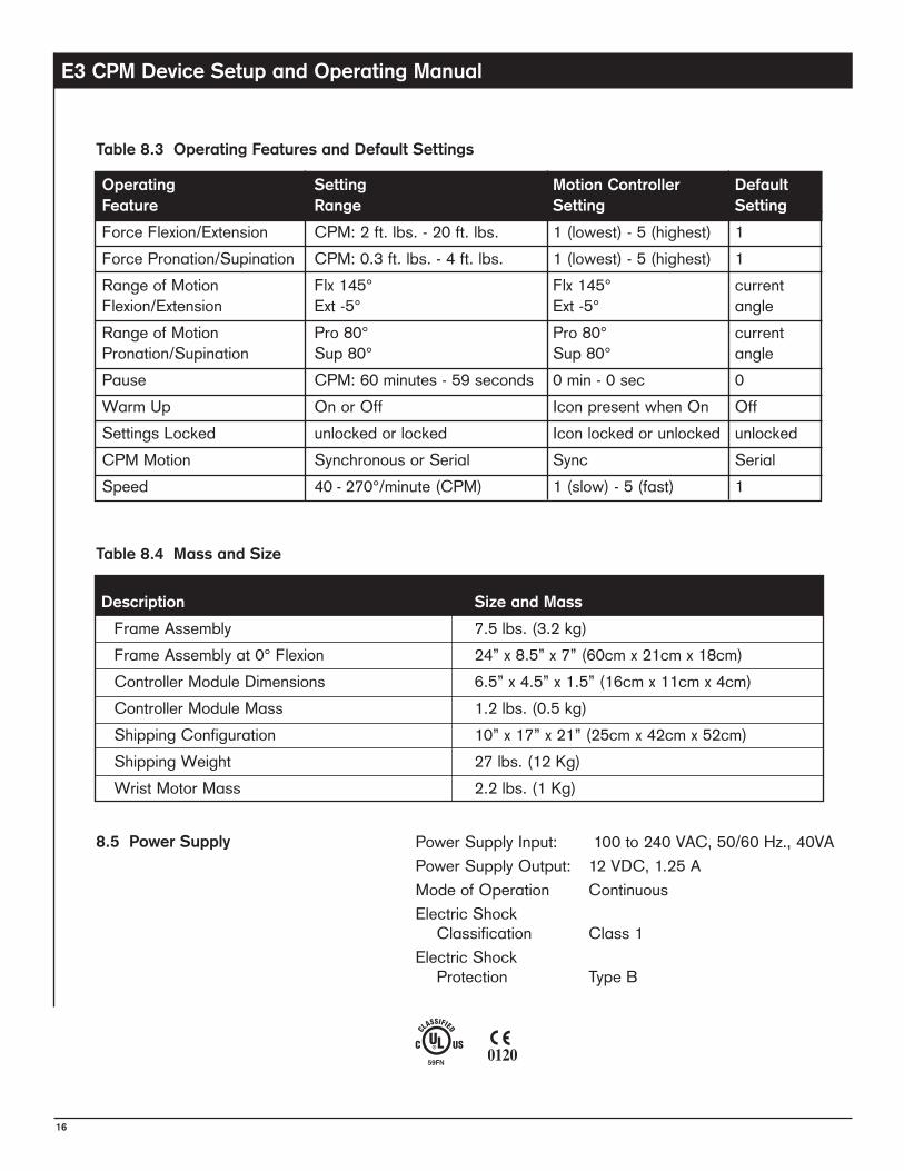
8.5 Power Supply PowerSupplyInput: 100to240VAC,50/60Hz.,40VAPowerSupplyOutput: 12VDC,1.25AModeofOperation ContinuousElectricShock Classification Class1ElectricShock Protection TypeB
Operating Setting Motion Controller Default Feature Range Setting Setting
ForceFlexion/Extension CPM:2ft.lbs.-20ft.lbs. 1(lowest)-5(highest) 1ForcePronation/Supination CPM:0.3ft.lbs.-4ft.lbs. 1(lowest)-5(highest) 1RangeofMotion Flx145° Flx145° currentFlexion/Extension Ext-5° Ext-5° angleRangeofMotion Pro80° Pro80° currentPronation/Supination Sup80° Sup80° anglePause CPM:60minutes-59seconds 0min-0sec 0WarmUp OnorOff IconpresentwhenOn OffSettingsLocked unlockedorlocked Iconlockedorunlocked unlockedCPMMotion SynchronousorSerial Sync SerialSpeed 40-270°/minute(CPM) 1(slow)-5(fast) 1
Table 8.3 Operating Features and Default Settings
Description Size and Mass
FrameAssembly 7.5lbs.(3.2kg) FrameAssemblyat0°Flexion 24”x8.5”x7”(60cmx21cmx18cm) ControllerModuleDimensions 6.5”x4.5”x1.5”(16cmx11cmx4cm) ControllerModuleMass 1.2lbs.(0.5kg) ShippingConfiguration 10”x17”x21”(25cmx42cmx52cm) ShippingWeight 27lbs.(12Kg) WristMotorMass 2.2lbs.(1Kg)
Table 8.4 Mass and Size
E3 CPM Device Setup and Operating Manual
17
9.troubleshooting
10.symbolsuseD
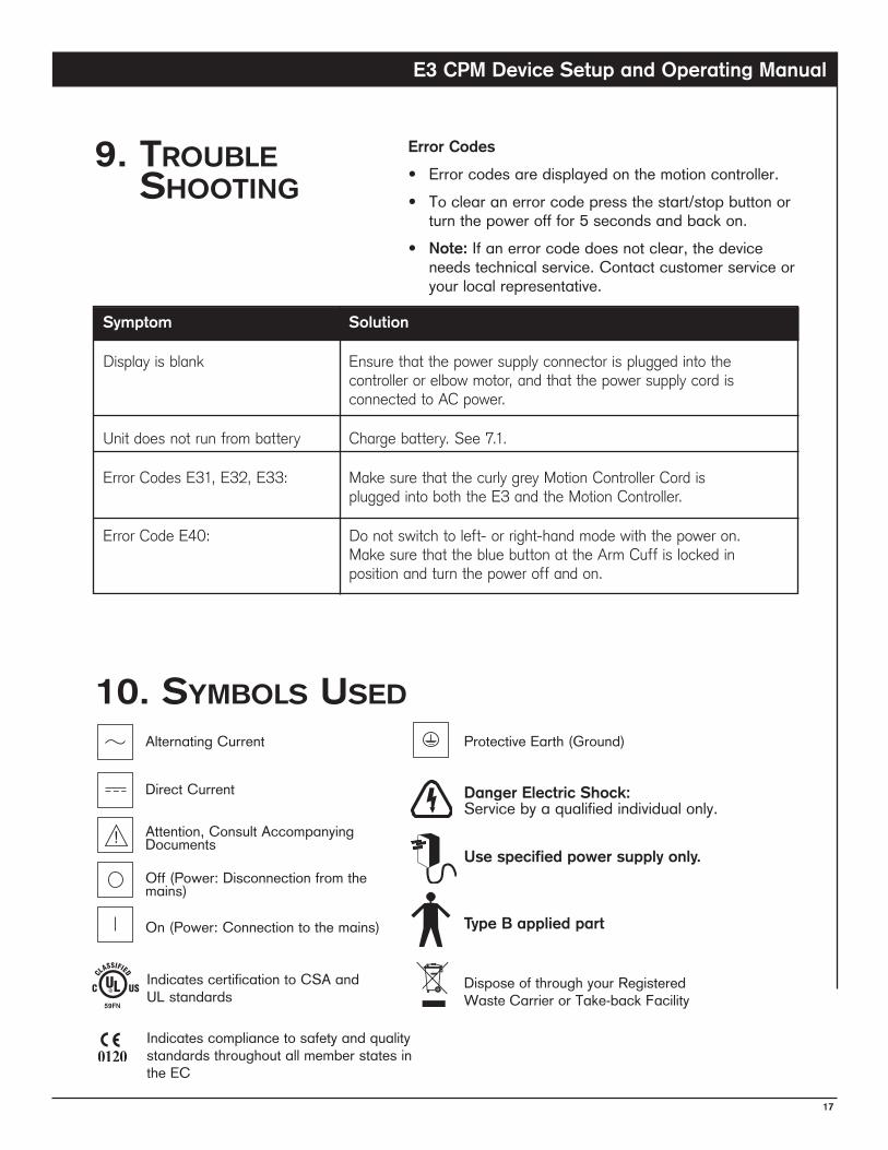
Symptom Solution
Display is blank Ensure that the power supply connector is plugged into the controller or elbow motor, and that the power supply cord is connected to AC power.
Unit does not run from battery Charge battery. See 7.1.
Error Codes E31, E32, E33: Make sure that the curly grey Motion Controller Cord is plugged into both the E3 and the Motion Controller.
Error Code E40: Do not switch to left- or right-hand mode with the power on. Make sure that the blue button at the Arm Cuff is locked in position and turn the power off and on.
Error Codes
• Errorcodesaredisplayedonthemotioncontroller.• Toclearanerrorcodepressthestart/stopbuttonor
turnthepowerofffor5secondsandbackon.• Note: Ifanerrorcodedoesnotclear,thedevice
needstechnicalservice.Contactcustomerserviceoryourlocalrepresentative.
Danger Electric Shock:Servicebyaqualifiedindividualonly.
Use specified power supply only.
Type B applied part
AlternatingCurrent
DirectCurrent
Attention,ConsultAccompanyingDocuments
Off(Power:Disconnectionfromthemains)
On(Power:Connectiontothemains)
ProtectiveEarth(Ground)
DisposeofthroughyourRegisteredWasteCarrierorTake-backFacility
IndicatescertificationtoCSAandULstandards
IndicatescompliancetosafetyandqualitystandardsthroughoutallmemberstatesintheEC
E3 CPM Device Setup and Operating Manual
18
11cautionsanDWarnings11.1 Read this manual before assembling or
using the E3 Elbow CPM (device). Use device only as described in this manual.
• Use the device only in accordance with the Physician prescription and Setup and Operating Instructions. Failure to do so may result in damage to the device and/or personal injury.
• The device should not be used in the presence of flammable anesthetics.
• Use only manufacturer’s supplied replacement components.
• Do not use the device if there are mental or physical conditions that preclude patient compliance.
• To prevent potential physical injury, such as strangulation and choking hazards, keep the device away from children or individuals with mental or physical conditions that preclude the safe use of the device.
• Position the device in a comfortable and secure position. Ensure that the device is stable through its full range of motion.
• Keep hair, loose clothing, fingers and all parts of body away from moving components of the device.
• Do not expose the device to water or extreme temperatures. Do not use the device on waterbeds. See Section 7.6 for the recommended Operating and Storage Conditions.
• Do not use the device near exposed flames, while smoking or near excessive heat.
• Disconnect the electrical supply before servicing or cleaning. Failure to do so could result in electrical shock or personal injury.
• Turn the power off before unplugging.
• Unplug the power supply by grasping the plug not the cord.
• Unless using the device or recharging the battery, turn the device off and unplug from the power supply.
• Do not use the device power supply or motion controller if it appears damaged or if there are exposed wires.
• Store the device and component parts in the carrying case when not in use.
• Do not pour cleaning solution directly onto the device. This may allow fluids to enter the device and cause electrical problems, or wash lubricants away from running components, reducing the life span of the device.
• Select a location for the device and device components (motion controller, straps, cables and power supply) to prevent a tripping hazard during use.
Contraindications
Do not use the device if any of the following are present:• Untreated or uncontrolled infection.• Unstable fractures.• Hemorrhage.
Note: Upon using the device, if signs of infection such as hyperthermia, fever, redness, irritation, warmth, swelling, bleeding, and/or increased persistent pain are present, discontinue operation of the device and contact the patient’s physician. Do not proceed with treatment until the physician has approved continued use of the device.
Note: Refer to the E3 Technical Service Manual for further specifications or contact your local distributor
E3 CPM Device Setup and Operating Manual
19
12Warranty/serviceNew Product Limited Warranty
The Manufacturer warrants the product to be free from defects in material and workmanship for a period of (2) two years for all major components (motor, power transmission parts and circuit boards) and for a period of 90 days for all housing parts, knobs, hardware and sub-assemblies (excluding disposables). The warranty takes effect from the date of the original purchase from the Manufacturer, or its Authorized Distributor, and provided the product is new and unused. No warranty shall apply if the product has been lost, or damaged by accident, abuse, misuse, or misapplication, or as a result of service or modification by other than a person authorized by the Manufacturer. This warranty shall only apply to the original buyer of the product and is non transferable. The Manufacturer’s liability under this warranty, and the original buyer’s exclusive remedy, is limited to the cost of materials and labor to repair the defective product, or to its replacement, and in no event shall exceed the purchase price.
To obtain warranty service the product must be returned freight prepaid to the Manufacturer or the selling distributor, with a clear indication as to the defect. Upon receipt of a product returned under warranty, the Manufacturer will inspect the product and will notify the buyer of the extent of repair or replacement which the Manufacturer will perform under warranty. If the product is received incomplete, missing parts will automatically be replaced at the buyer’s expense. The Manufacturer also reserves the right, at its own cost, to upgrade or replace parts or sub-assemblies to the latest production standards. The Manufacturer will normally perform the repair and return the product, or provide a replacement, within (30) days from the day of receipt, freight collect.
THE MANUFACTURER IS NOT RESPONSIBLE FOR INCIDENTAL OR CONSEQUENTIAL DAMAGES RESULTING FROM THE BREACH OF ANY EXPRESSED OR IMPLIED WARRANTY, INCLUDING DAMAGE FOR PERSONAL INJURY. THE WARRANTY CONTAINED HEREIN IS IN LIEU OF ALL WARRANTIES, EXPRESSED OR IMPLIED, INCLUDING IMPLIED WARRANTIES OF MERCHANTABILITY AND FITNESS FOR A PARTICULAR PURPOSE. NO STATEMENT OF ANY REPRESENTATIVE SHALL EXTEND THE MANUFACTURER’S LIABILITY AS HEREIN ESTABLISHED OR LIMITED.
Returning the Device for Service
Should the device require warranty repair, the buyer must contact either the Customer Service department (outside the USA contact International Customer Service), or the authorized distributor from which the device was purchased for return instructions.
If the device needs to be returned for any repair, pack the components in the original shipping container and contact your local dealer/distributor or the manufacturer (see page 22).Note: Please enclose the following information when returning the device:
• Return Authorization Number
• Ship-to Address
• Purchase order for non-warranty repairs
• Name and phone number of a person to contact
• Brief description of the problem

E3 CPM Device Setup and Operating Manual
20
notes


RSQR Ltd. Ludgate House, 107-111 Fleet Street, London EC4A 2AB [email protected] www.rsqa.co.uk
ORTHOREHAB901 Dillingham Road, Pickering, Ontario L1W 2Y5 CanadaIntl. Tel: 1-905-420-3303 Fax: 1-905-420-3970
ORTHOREHAB is registered to ISO13485 for Quality Assurance