PastLS1 Qseven carrier board for Rakun LS1 - Borea · Version 1.1 2 INTRODUCTION 2.1 DEVICE...
37
PastLS1 Qseven carrier board for Rakun LS1 $HeadURL: https://svn.borea.si/svn/docs/rakun/rakun_pastls1/B01088/docs/PastLS1_DS.fodt $ $Rev: 1047 $ $Date: 2016-04-07 10:34:34 +0200 (čet, 07 apr 2016) $
Transcript of PastLS1 Qseven carrier board for Rakun LS1 - Borea · Version 1.1 2 INTRODUCTION 2.1 DEVICE...

PastLS1 Qseven carrier board for Rakun LS1
$HeadURL: https://svn.borea.si/svn/docs/rakun/rakun_pastls1/B01088/docs/PastLS1_DS.fodt $$Rev: 1047 $ $Date: 2016-04-07 10:34:34 +0200 (čet, 07 apr 2016) $

Version 1.1
TABLE OF CONTENTS
1 GENERAL....................................................................................................... 71.1 About this document.................................................................................... 71.2 Revision history........................................................................................... 7
2 INTRODUCTION............................................................................................. 82.1 Device overview.......................................................................................... 82.2 Features...................................................................................................... 8
3 INSTALLATION GUIDE................................................................................. 10
4 ARCHITECTURE........................................................................................... 124.1 Block diagram........................................................................................... 124.2 USB connection........................................................................................ 124.3 UART connection...................................................................................... 13
5 JUMPERS......................................................................................................145.1 Boot select jumper P15............................................................................. 145.2 USB direction jumpers P8 and P11........................................................... 145.3 USB mode jumpers P12 and P13..............................................................155.4 UART to USB selection jumpers P16 and P17.......................................... 15
6 LED INDICATORS......................................................................................... 16
7 CONNECTOR DETAILS................................................................................ 177.1 Qseven connector P7................................................................................ 187.2 Power supply connector SW1................................................................... 217.3 Ethernet connector CON1......................................................................... 217.4 Micro SD card connector J1...................................................................... 227.5 I2C connector P3...................................................................................... 227.6 SATA connector J6.................................................................................... 237.7 SATA power connector P18....................................................................... 237.8 HDMI connector P1................................................................................... 247.9 USB 3.0 HOST connector J4.....................................................................257.10 USB OTG connector J5...........................................................................257.11 Mini PCI-e connector P2.......................................................................... 267.12 Quicc Engine connector P10................................................................... 27
PastLS1 Qseven carrier board for Rakun LS1
Version 1.1
7.13 GPIO1/EC3 connector P9....................................................................... 287.14 GPIO2/EC2 connector P14..................................................................... 297.15 MikroBUS connector P4+P5....................................................................307.16 UART connector P6.................................................................................307.17 Debug console connector J7................................................................... 317.18 AUX SerDes connectors J8, J2, J3.........................................................31
8 APPENDIX A: PHYBOARD ADD-ON BOARD..............................................338.1 Architecture............................................................................................... 338.2 Jumpers.................................................................................................... 348.2.1 Ethernet Mode jumper P1.....................................................................348.2.2 Address jumper P2............................................................................... 34
8.3 LED indicators........................................................................................... 348.4 Connector details...................................................................................... 358.4.1 EC connector P4.................................................................................. 358.4.2 Ethernet connector P5.......................................................................... 35
9 APPENDIX B: MIKROBUS SLOT................................................................. 36
PastLS1 Qseven carrier board for Rakun LS1
Version 1.1
ILLUSTRATION INDEX
Illustration 2.1: PastLS1........................................................................................ 8Illustration 3.1: Installation...................................................................................10Illustration 4.1: Block diagram............................................................................. 12Illustration 4.2: USB connection.......................................................................... 13Illustration 4.3: UART connection........................................................................ 13Illustration 5.1: Position of jumpers..................................................................... 14Illustration 6.1: LED indicator.............................................................................. 16Illustration 7.1: Position of connectors.................................................................17Illustration 7.2: Position of connectors.................................................................17Illustration 8.1: PHYBoard add-on....................................................................... 33Illustration 8.2: Block diagram of PHYBoard....................................................... 33
PastLS1 Qseven carrier board for Rakun LS1
Version 1.1
INDEX OF TABLES
Table 1.1: Revision history.................................................................................... 7Table 3.1: Default jumper positions..................................................................... 10Table 5.1: Boot select jumper P15.......................................................................14Table 5.2: USB direction jumpers P8 and P11.....................................................15Table 5.3: USB mode jumpers P12 and P13....................................................... 15Table 5.4: UART to USB selection jumpers P16 and P17...................................15Table 6.1: LED indicators.................................................................................... 16Table 7.1: Qseven edge connector type.............................................................. 18Table 7.2: Qseven edge connector pinout........................................................... 20Table 7.3: Power supply connector type..............................................................21Table 7.4: Power supply connector pinout...........................................................21Table 7.5: Ethernet connector type......................................................................21Table 7.6: Ethernet connector pinout...................................................................21Table 7.7: Ethernet LEDs.................................................................................... 21Table 7.8: Micro SD card connector type............................................................22Table 7.9: Micro SD card connector pinout..........................................................22Table 7.10: I2C connector type........................................................................... 22Table 7.11: I2C connector pinout......................................................................... 22Table 7.12: SATA connector type........................................................................ 23Table 7.13: SATA connector pinout..................................................................... 23Table 7.14: SATA power connector type.............................................................. 23Table 7.15: SATA power connector pinout........................................................... 23Table 7.16: HDMI connector type........................................................................ 24Table 7.17: HDMI connector pinout..................................................................... 24Table 7.18: USB 3.0 connector type.................................................................... 25Table 7.19: USB 3.0 connector pinout................................................................. 25Table 7.20: USB OTG connector type................................................................. 25Table 7.21: USB OTG connector pinout.............................................................. 25Table 7.22: Mini PCIe connector type..................................................................26Table 7.23: Mini PCIe connector pinuot...............................................................26Table 7.24: QUICC Engine connector type..........................................................27Table 7.25: QUICC Engine connector pinout.......................................................27Table 7.26: GPIO1/EC3 connector type.............................................................. 28Table 7.27: GPIO1/EC3 connector pinout........................................................... 28Table 7.28: GPIO2/EC2 connector type.............................................................. 29Table 7.29: GPIO2/EC2 connector pinout........................................................... 29Table 7.30: Microbus connector type...................................................................30Table 7.31: Microbus connector pinout................................................................30Table 7.32: UART connector type....................................................................... 30Table 7.33: UART connector pinout.................................................................... 30Table 7.34: Debug console connector type......................................................... 31Table 7.35: Debug console connector pinout...................................................... 31Table 7.36: AUX SerDes connector type............................................................. 31Table 7.37: AUX SerDes 1 connector pinout....................................................... 31Table 7.38: AUX SerDes 2 connector pinout....................................................... 32Table 7.39: AUX SerDes 3 connector pinout....................................................... 32Table 8.1: Ethernet mode selection jumper P1.................................................... 34Table 8.2: UART to USB selection jumpers P16 and P17...................................34Table 8.3: Ethernet LEDs.................................................................................... 34Table 8.4: EC connector type.............................................................................. 35
PastLS1 Qseven carrier board for Rakun LS1
Version 1.1
Table 8.5: EC connector extended pinout...........................................................35Table 8.6: Ethernet connector type......................................................................35Table 8.7: Ethernet connector pinout...................................................................35Table 9.1: Currently available Click boards from Mikroelektronika......................36
PastLS1 Qseven carrier board for Rakun LS1
Version 1.1
1 GENERAL
1.1 ABOUT THIS DOCUMENT
This document defines the hardware architecture of the RakunLS1 Qseven module.
1.2 REVISION HISTORY
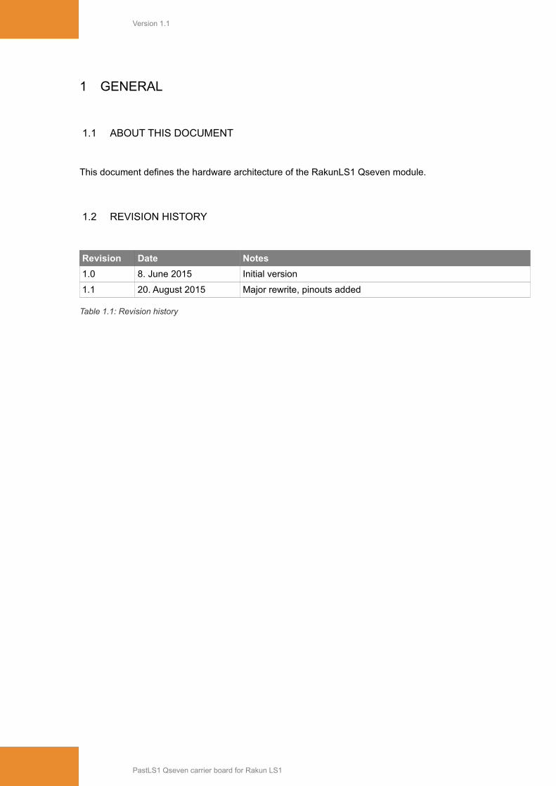
Revision Date Notes
1.0 8. June 2015 Initial version
1.1 20. August 2015 Major rewrite, pinouts added
Table 1.1: Revision history
PastLS1 Qseven carrier board for Rakun LS1

Version 1.1
2 INTRODUCTION
2.1 DEVICE OVERVIEW
PastLS1 is Qseven carrier board that in addition to standard Qseven features supports additional interfacesprovided by Borea RakunLS1 Qseven module.
RakunLS1 module can be strictly Qseven compliant or can be configured to expose Freescale QorIQspecific interfaces. In such RakunLS1 module configurations modified carrier board must be used to fullyutilize module interfaces.
Illustration 2.1: PastLS1
2.2 FEATURES
Qseven slotSupports Qseven standard 2.0 + additional proprietary pins used for QorIQ specifics, present on a RakunLS1 board.
Ethernet Interfaces10/100/1000Mb/s Ethernet port, IEEE1588• 2x RGMII ports (multiplexed with GPIOs and other interfaces) available on pin headers • 2x SGMII ports available on debug connectors• Ethernet add-on board for RGMII ports available. Supports 1000BaseT and 1000BaseX
USB InterfacesSingle USB port. Works as:• USB 3.0 routed to USB 3.0 connector or
PastLS1 Qseven carrier board for Rakun LS1

Version 1.1
• USB 2.0 routed to USB 3.0 connector or• USB 2.0 routed to mPCIe slot or• USB OTG routed to USB OTG connector
SATASATA 3.0 with power connector 5V
HDMI InterfaceHDMI 1.3
SD cardMicroSD slot. Rakun supports booting from SD
PCIe InterfaceMiniPCIe slot with PCIe 0 lane from Qseven and USBNormal, half and extended size supported
UARTsFour 16450/16650 compatible UARTs with FIFOs. CMOS levels interfaces. Two of them can be routed to theUSB2UART converter.Two additional QUICCEngine UART interfaces.
Debug consoleUSB to UART converter implemented on board for easier PC connectivityUART1 or UART2 from Qseven can be routed to the console
GPIOTwo GPIO connectors with 26 GPIO signals availableGPIO1 interface is multiplexed with RGMII, CAN, USB2GPIO2 interface is multiplexed with RGMII, IEEE1588, PWM
QUICCEngineTwo UCCs, supporting TDM, HDLC, Bisync, UART, Transparent …QE interface is multiplexed with I2S, S/PDIF, GPIO, HDMI.
MikroBUSMikroBus module slot for extension purposes (SPI, UART, I2C). Allows connecting many of the shelf extension boards.
Aux SerDesRemaining three SerDes lanes from Qseven (Lane 0 is used for PCIe) are available on auxiliary testing connectors. SATA type connectors. Available interfaces:• Up to 3x PCIe• Additional SATA• 2x SGMII
Power Supply5V DC, 2A InputOnboard regulators for 1.5V and 3.3V.Typical power consumption depends on application. Power consumption without USB, Qseven board and miniPCIe board: 8mA.
PhysicalPhysical Dimensions: 143 × 92 mm.
EnvironmentStorage: -65ºC to +150ºCOperation: -40ºC to +85ºCHumidity: 5% to 90% Non-CondensingElectrostatic Discharge Tolerance: 2KVPb free, ROHS compliant
PastLS1 Qseven carrier board for Rakun LS1

Version 1.1
3 INSTALLATION GUIDE
Before start, perform the steps described below. Check figure 7.1 for the position of connectors and figure5.1 for the position of jumpers.
1. Attach RakunLS1 and (optionally) PHYBoard add-on as shown in figure below:
Illustration 3.1: Installation
2. Check presence of the following jumpers:
Jumper Setting Function
P13 1 – 2 USB is connected to USB connectors
P12 1 – 2 USB is connected to USB connectors
P11 1 – 2 USB is connected to USB3.0 connector
P8 1 – 2 USB is connected to USB3.0 connector
P15 1 – 2 SD Boot
P16 2 – 3 Console is UART2
P17 2 – 3 Console is UART2
Table 3.1: Default jumper positions
3. Install uSD card with boot image to uSD slot.4. Attach PC to Console connector with USB cable. Start terminal application on PC. Set it to 115200 kb/s, 8bit, no parity, one stop bit (115200 8N1).5. Optionally attach Ethernet, HDMI, USB.
PastLS1 Qseven carrier board for Rakun LS1

Version 1.1
6. Connect external 5V power supply to DC power jack.7. RakunLS1 will boot from SD card. There will be u-boot prompt in the terminal.
PastLS1 Qseven carrier board for Rakun LS1
Version 1.1
4 ARCHITECTURE
4.1 BLOCK DIAGRAM
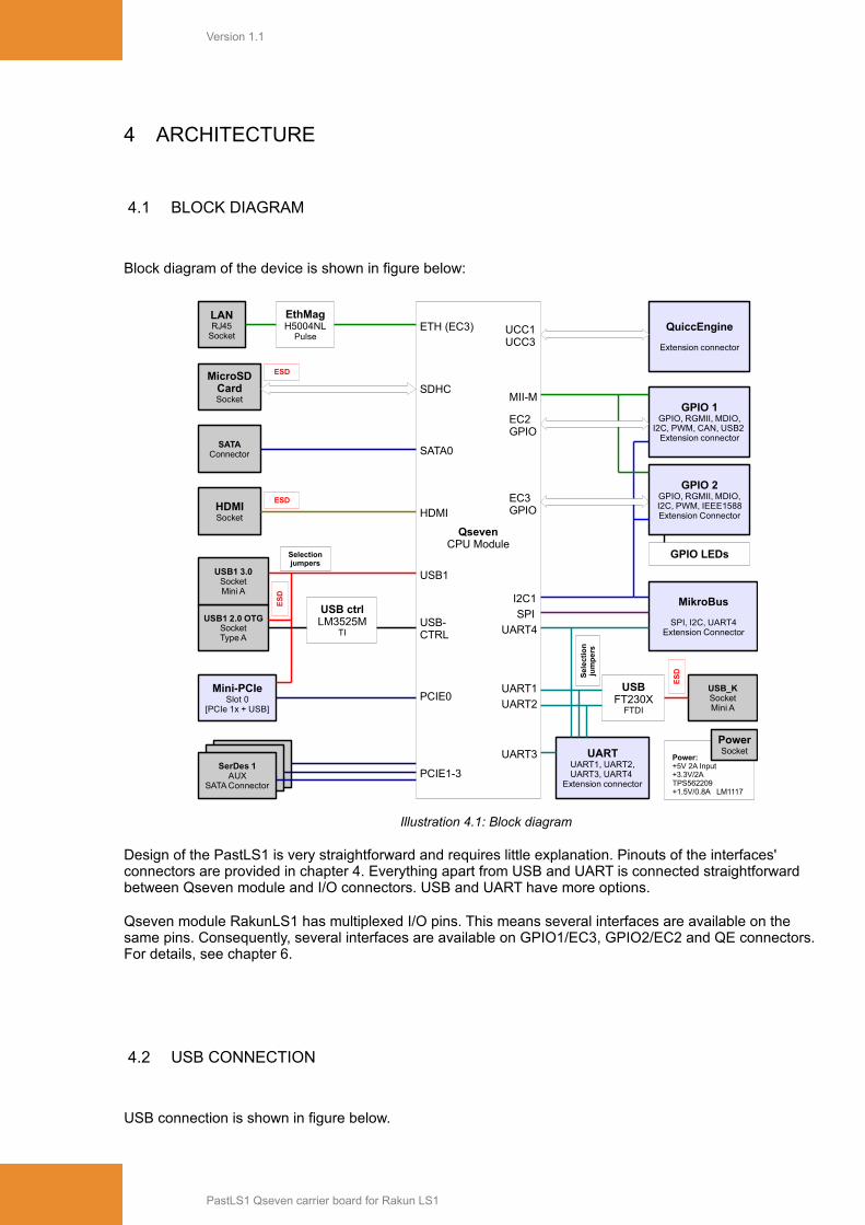
Block diagram of the device is shown in figure below:
Illustration 4.1: Block diagram
Design of the PastLS1 is very straightforward and requires little explanation. Pinouts of the interfaces' connectors are provided in chapter 4. Everything apart from USB and UART is connected straightforward between Qseven module and I/O connectors. USB and UART have more options.
Qseven module RakunLS1 has multiplexed I/O pins. This means several interfaces are available on the same pins. Consequently, several interfaces are available on GPIO1/EC3, GPIO2/EC2 and QE connectors. For details, see chapter 6.
4.2 USB CONNECTION
USB connection is shown in figure below.
PastLS1 Qseven carrier board for Rakun LS1
GPIO 1GPIO, RGMII, MDIO,
I2C, PWM, CAN, USB2Extension connector
GPIO 2GPIO, RGMII, MDIO,I2C, PWM, IEEE1588Extension Connector
MikroBus
SPI, I2C, UART4Extension Connector
QuiccEngine
Extension connector
USBFT230X
FTDI
USB ctrlLM3525M
TI
LANRJ45
Socket
EthMagH5004NL
Pulse
GPIO LEDs
SerDes3
AUXSATA Connector
SerDes 2AUX
SATA Connector
QsevenCPU Module
HDMI
SATA0
PCIE0
UCC1UCC3
UART4
SDHC
SPI
I2C1
EC2GPIO
USB-CTRL
ETH (EC3)
MII-M
USB1
Mini-PCIeSlot 0
[PCIe 1x + USB]
MicroSDCardSocket
USB_KSocketMini A
USB1 2.0 OTGSocketType A
SATAConnector
USB1 3.0SocketMini A
HDMISocket
SerDes 1AUX
SATA Connector
UARTUART1, UART2,UART3, UART4
Extension connector
EC3GPIO
UART3
UART2
UART1
PCIE1-3
Power:+5V 2A Input+3.3V/2ATPS562209 +1.5V/0.8A LM1117
PowerSocket
ESD
ESD
ES
D
ES
D
Selectionjumpers
Sel
ect
ion
jum
pe
rs
Version 1.1
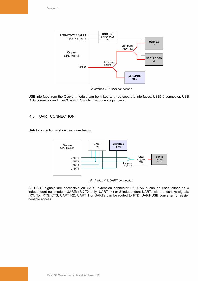
Illustration 4.2: USB connection
USB interface from the Qseven module can be linked to three separate interfaces: USB3.0 connector, USBOTG connector and miniPCIe slot. Switching is done via jumpers.
4.3 UART CONNECTION
UART connection is shown in figure below:
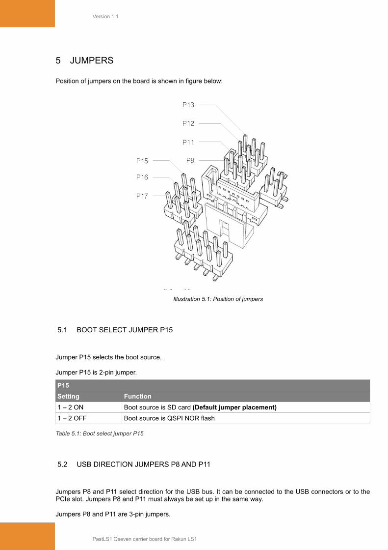
Illustration 4.3: UART connection
All UART signals are accessible on UART extension connector P6. UARTs can be used either as 4independent null-modem UARTs (RX-TX only; UART1-4) or 2 independent UARTs with handshake signals(RX, TX, RTS, CTS; UART1-2). UART 1 or UART2 can be routed to FTDI UART-USB converter for easierconsole access.
PastLS1 Qseven carrier board for Rakun LS1
USB ctrlLM3525M
TI
QsevenCPU Module
USB-POWERFAULT
USB1
Mini-PCIeSlot
USB1 2.0 OTGJ5
USB1 3.0J4
USB-DRVBUS
JumpersP8/P11
JumpersP12/P13
MikroBusSlot
USBFT230X
FTDI
QsevenCPU Module
UART4
USB_KSocketMini A
UART3
UART2
UART1
UARTP6
JumpersP16/P17
Version 1.1
5 JUMPERS
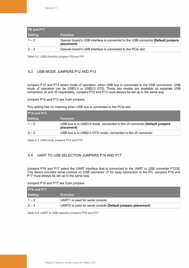
Position of jumpers on the board is shown in figure below:
Illustration 5.1: Position of jumpers
5.1 BOOT SELECT JUMPER P15
Jumper P15 selects the boot source.
Jumper P15 is 2-pin jumper.
P15
Setting Function
1 – 2 ON Boot source is SD card (Default jumper placement)
1 – 2 OFF Boot source is QSPI NOR flash
Table 5.1: Boot select jumper P15
5.2 USB DIRECTION JUMPERS P8 AND P11
Jumpers P8 and P11 select direction for the USB bus. It can be connected to the USB connectors or to thePCIe slot. Jumpers P8 and P11 must always be set up in the same way.
Jumpers P8 and P11 are 3-pin jumpers.
PastLS1 Qseven carrier board for Rakun LS1
P17
P16
P15 P8
P11
P12
P13
Version 1.1
P8 and P11
Setting Function
1 – 2 Qseven board’s USB interface is connected to the USB connector (Default jumpersplacement)
2 – 3 Qseven board’s USB interface is connected to the PCIe slot
Table 5.2: USB direction jumpers P8 and P11
5.3 USB MODE JUMPERS P12 AND P13
Jumpers P12 and P13 select mode of operation, when USB bus is connected to the USB connectors. USBmode of operation can be USB3.0 or USB2.0 OTG. These two modes are available on separate USBconnectors J4 and J5 respectably. Jumpers P12 and P13 must always be set up in the same way.
Jumpers P12 and P13 are 3-pin jumpers.
This setting has no meaning when USB bus is connected to the PCIe slot.
P12 and P13
Setting Function
1 – 2 USB bus is in USB3.0 mode, connected to the J4 connector (Default jumpers placement)
2 – 3 USB bus is in USB2.0 OTG mode, connected to the J5 connector
Table 5.3: USB mode jumpers P12 and P13
5.4 UART TO USB SELECTION JUMPERS P16 AND P17
Jumpers P16 and P17 select the UART interface that is connected to the UART to USB converter FT230.This device provides serial console on USB connector J7 for easy connection to the PC. Jumpers P16 andP17 must always be set up in the same way.
Jumpers P16 and P17 are 3-pin jumpers.
P16 and P17
Setting Function
1 – 2 UART1 is used for serial console
2 – 3 UART2 is used for serial console (Default jumpers placement)
Table 5.4: UART to USB selection jumpers P16 and P17
PastLS1 Qseven carrier board for Rakun LS1

Version 1.1
6 LED INDICATORS
Board comprises three LED indicators.
Illustration 6.1: LED indicator
They are connected to the GPIO pins.
LED Signal Note
LED1 GPIO3_17 Active high
LED2 GPIO3_18 Active high
LED3 GPIO3_19 Active high
Table 6.1: LED indicators
PastLS1 Qseven carrier board for Rakun LS1
LED1LED2
LED3
Version 1.1
7 CONNECTOR DETAILS
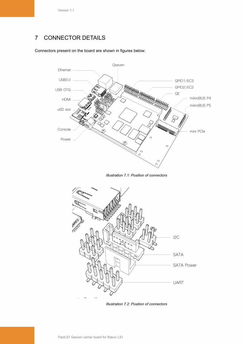
Connectors present on the board are shown in figures below:
Illustration 7.1: Position of connectors
Illustration 7.2: Position of connectors
PastLS1 Qseven carrier board for Rakun LS1
GPIO1/EC3
GPIO2/EC2
QE
QsevenEthernet
mikroBUS P4
mikroBUS P5
USB3.0
USB OTG
HDMI
uSD slot
Console
Power
mini PCIe
SATA
SATA Power
UART
I2C
Version 1.1
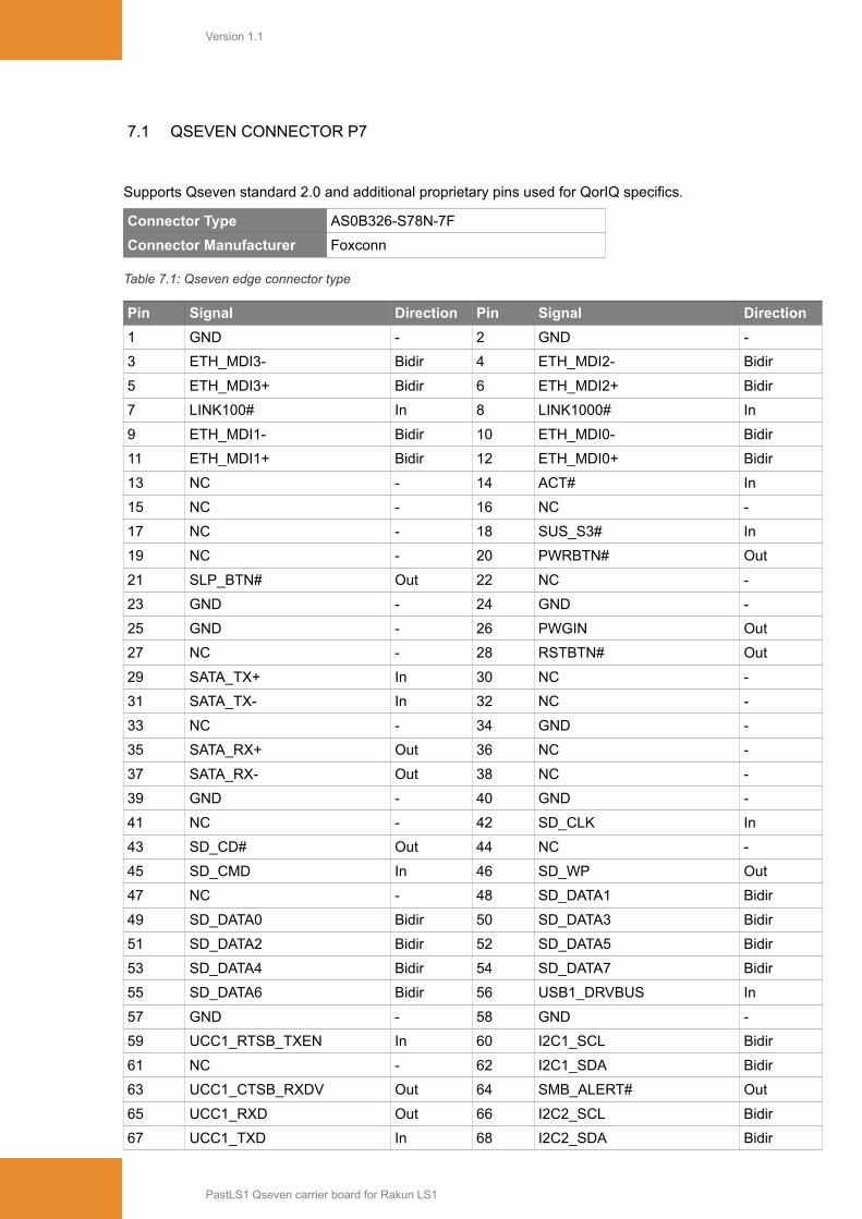
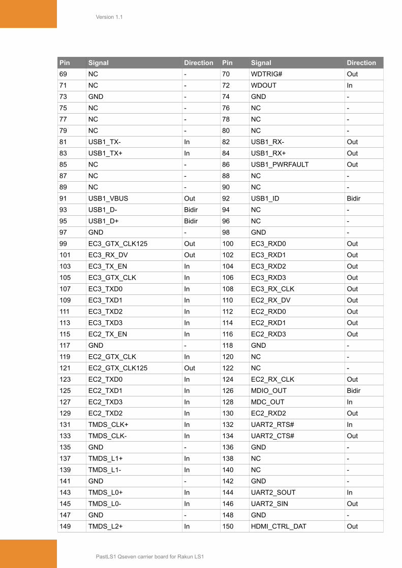
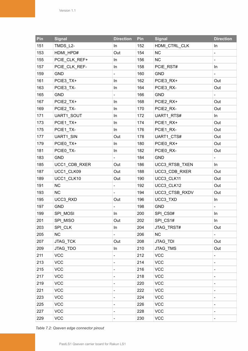
7.1 QSEVEN CONNECTOR P7
Supports Qseven standard 2.0 and additional proprietary pins used for QorIQ specifics.
Connector Type AS0B326-S78N-7F
Connector Manufacturer Foxconn
Table 7.1: Qseven edge connector type
Pin Signal Direction Pin Signal Direction
1 GND - 2 GND -
3 ETH_MDI3- Bidir 4 ETH_MDI2- Bidir
5 ETH_MDI3+ Bidir 6 ETH_MDI2+ Bidir
7 LINK100# In 8 LINK1000# In
9 ETH_MDI1- Bidir 10 ETH_MDI0- Bidir
11 ETH_MDI1+ Bidir 12 ETH_MDI0+ Bidir
13 NC - 14 ACT# In
15 NC - 16 NC -
17 NC - 18 SUS_S3# In
19 NC - 20 PWRBTN# Out
21 SLP_BTN# Out 22 NC -
23 GND - 24 GND -
25 GND - 26 PWGIN Out
27 NC - 28 RSTBTN# Out
29 SATA_TX+ In 30 NC -
31 SATA_TX- In 32 NC -
33 NC - 34 GND -
35 SATA_RX+ Out 36 NC -
37 SATA_RX- Out 38 NC -
39 GND - 40 GND -
41 NC - 42 SD_CLK In
43 SD_CD# Out 44 NC -
45 SD_CMD In 46 SD_WP Out
47 NC - 48 SD_DATA1 Bidir
49 SD_DATA0 Bidir 50 SD_DATA3 Bidir
51 SD_DATA2 Bidir 52 SD_DATA5 Bidir
53 SD_DATA4 Bidir 54 SD_DATA7 Bidir
55 SD_DATA6 Bidir 56 USB1_DRVBUS In
57 GND - 58 GND -
59 UCC1_RTSB_TXEN In 60 I2C1_SCL Bidir
61 NC - 62 I2C1_SDA Bidir
63 UCC1_CTSB_RXDV Out 64 SMB_ALERT# Out
65 UCC1_RXD Out 66 I2C2_SCL Bidir
67 UCC1_TXD In 68 I2C2_SDA Bidir
PastLS1 Qseven carrier board for Rakun LS1
Version 1.1
Pin Signal Direction Pin Signal Direction
69 NC - 70 WDTRIG# Out
71 NC - 72 WDOUT In
73 GND - 74 GND -
75 NC - 76 NC -
77 NC - 78 NC -
79 NC - 80 NC -
81 USB1_TX- In 82 USB1_RX- Out
83 USB1_TX+ In 84 USB1_RX+ Out
85 NC - 86 USB1_PWRFAULT Out
87 NC - 88 NC -
89 NC - 90 NC -
91 USB1_VBUS Out 92 USB1_ID Bidir
93 USB1_D- Bidir 94 NC -
95 USB1_D+ Bidir 96 NC -
97 GND - 98 GND -
99 EC3_GTX_CLK125 Out 100 EC3_RXD0 Out
101 EC3_RX_DV Out 102 EC3_RXD1 Out
103 EC3_TX_EN In 104 EC3_RXD2 Out
105 EC3_GTX_CLK In 106 EC3_RXD3 Out
107 EC3_TXD0 In 108 EC3_RX_CLK Out
109 EC3_TXD1 In 110 EC2_RX_DV Out
111 EC3_TXD2 In 112 EC2_RXD0 Out
113 EC3_TXD3 In 114 EC2_RXD1 Out
115 EC2_TX_EN In 116 EC2_RXD3 Out
117 GND - 118 GND -
119 EC2_GTX_CLK In 120 NC -
121 EC2_GTX_CLK125 Out 122 NC -
123 EC2_TXD0 In 124 EC2_RX_CLK Out
125 EC2_TXD1 In 126 MDIO_OUT Bidir
127 EC2_TXD3 In 128 MDC_OUT In
129 EC2_TXD2 In 130 EC2_RXD2 Out
131 TMDS_CLK+ In 132 UART2_RTS# In
133 TMDS_CLK- In 134 UART2_CTS# Out
135 GND - 136 GND -
137 TMDS_L1+ In 138 NC -
139 TMDS_L1- In 140 NC -
141 GND - 142 GND -
143 TMDS_L0+ In 144 UART2_SOUT In
145 TMDS_L0- In 146 UART2_SIN Out
147 GND - 148 GND -
149 TMDS_L2+ In 150 HDMI_CTRL_DAT Out
PastLS1 Qseven carrier board for Rakun LS1
Version 1.1
Pin Signal Direction Pin Signal Direction
151 TMDS_L2- In 152 HDMI_CTRL_CLK In
153 HDMI_HPD# Out 154 NC -
155 PCIE_CLK_REF+ In 156 NC -
157 PCIE_CLK_REF- In 158 PCIE_RST# In
159 GND - 160 GND -
161 PCIE3_TX+ In 162 PCIE3_RX+ Out
163 PCIE3_TX- In 164 PCIE3_RX- Out
165 GND - 166 GND -
167 PCIE2_TX+ In 168 PCIE2_RX+ Out
169 PCIE2_TX- In 170 PCIE2_RX- Out
171 UART1_SOUT In 172 UART1_RTS# In
173 PCIE1_TX+ In 174 PCIE1_RX+ Out
175 PCIE1_TX- In 176 PCIE1_RX- Out
177 UART1_SIN Out 178 UART1_CTS# Out
179 PCIE0_TX+ In 180 PCIE0_RX+ Out
181 PCIE0_TX- In 182 PCIE0_RX- Out
183 GND - 184 GND -
185 UCC1_CDB_RXER Out 186 UCC3_RTSB_TXEN In
187 UCC1_CLK09 Out 188 UCC3_CDB_RXER Out
189 UCC1_CLK10 Out 190 UCC3_CLK11 Out
191 NC - 192 UCC3_CLK12 Out
193 NC - 194 UCC3_CTSB_RXDV Out
195 UCC3_RXD Out 196 UCC3_TXD In
197 GND - 198 GND -
199 SPI_MOSI In 200 SPI_CS0# In
201 SPI_MISO Out 202 SPI_CS1# In
203 SPI_CLK In 204 JTAG_TRST# Out
205 NC - 206 NC -
207 JTAG_TCK Out 208 JTAG_TDI Out
209 JTAG_TDO In 210 JTAG_TMS Out
211 VCC - 212 VCC -
213 VCC - 214 VCC -
215 VCC - 216 VCC -
217 VCC - 218 VCC -
219 VCC - 220 VCC -
221 VCC - 222 VCC -
223 VCC - 224 VCC -
225 VCC - 226 VCC -
227 VCC - 228 VCC -
229 VCC - 230 VCC -
Table 7.2: Qseven edge connector pinout
PastLS1 Qseven carrier board for Rakun LS1
Version 1.1
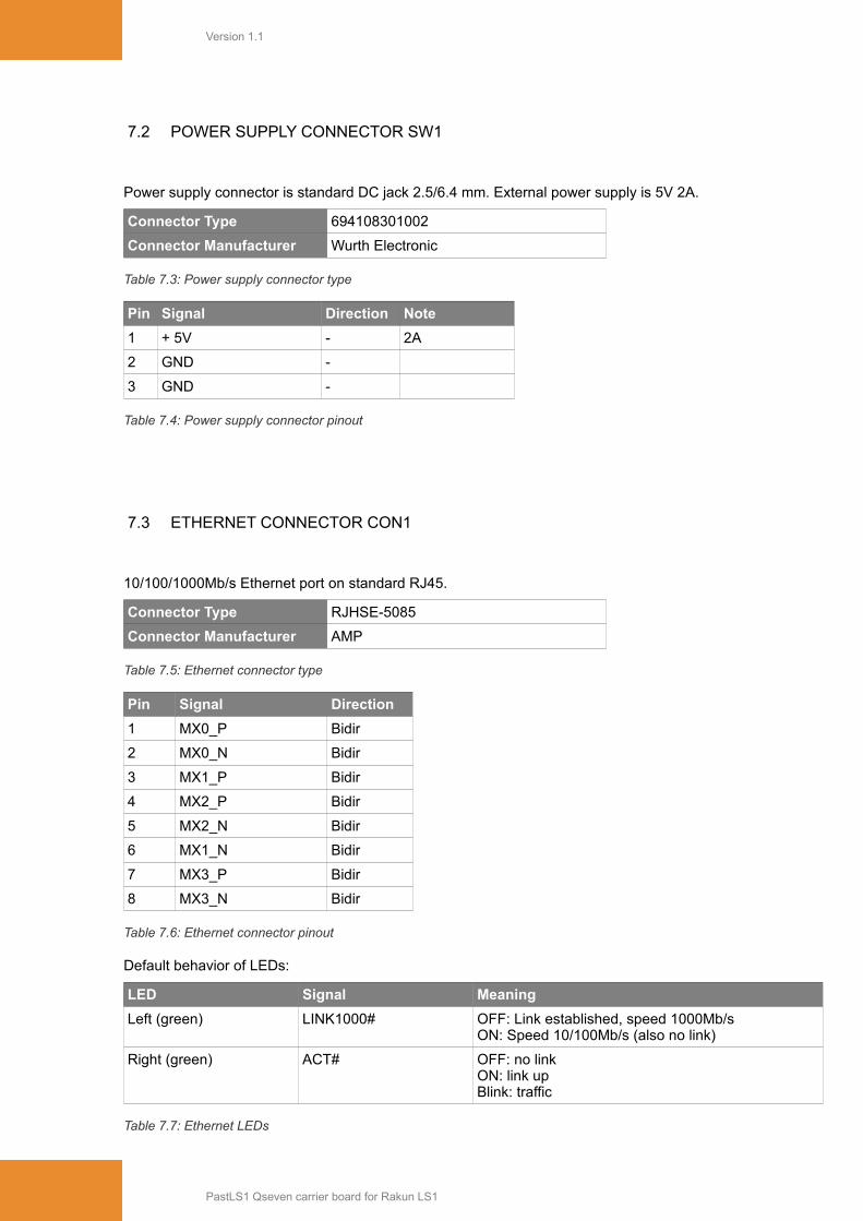
7.2 POWER SUPPLY CONNECTOR SW1
Power supply connector is standard DC jack 2.5/6.4 mm. External power supply is 5V 2A.
Connector Type 694108301002
Connector Manufacturer Wurth Electronic
Table 7.3: Power supply connector type
Pin Signal Direction Note
1 + 5V - 2A
2 GND -
3 GND -
Table 7.4: Power supply connector pinout
7.3 ETHERNET CONNECTOR CON1
10/100/1000Mb/s Ethernet port on standard RJ45.
Connector Type RJHSE-5085
Connector Manufacturer AMP
Table 7.5: Ethernet connector type
Pin Signal Direction
1 MX0_P Bidir
2 MX0_N Bidir
3 MX1_P Bidir
4 MX2_P Bidir
5 MX2_N Bidir
6 MX1_N Bidir
7 MX3_P Bidir
8 MX3_N Bidir
Table 7.6: Ethernet connector pinout
Default behavior of LEDs:
LED Signal Meaning
Left (green) LINK1000# OFF: Link established, speed 1000Mb/sON: Speed 10/100Mb/s (also no link)
Right (green) ACT# OFF: no linkON: link upBlink: traffic
Table 7.7: Ethernet LEDs
PastLS1 Qseven carrier board for Rakun LS1

Version 1.1
7.4 MICRO SD CARD CONNECTOR J1
Connector Type 693071010811
Connector Manufacturer Wurth Electronic
Table 7.8: Micro SD card connector type
Pin Signal Direction Note
1 DATA2 Bidir Pullup
2 DATA3 Bidir Pullup
3 CMD Out Pullup
4 VDD -
5 CLK Out Pullup
6 GND -
7 DATA0 Bidir Pullup
8 DATA1 Bidir Pullup
9 CD In
10 CD In Pullup
Table 7.9: Micro SD card connector pinout
7.5 I2C CONNECTOR P3
I2C bus is available on this connector. Power and GND is available also for easier expansion.
Connector Type 61030421121
Connector Manufacturer Wurth Electronic
Table 7.10: I2C connector type
Pin Signal Direction Note
1 3.3V In
2 I2C1_SDA In
3 I2C1_SCL Out
4 GND Out
Table 7.11: I2C connector pinout
PastLS1 Qseven carrier board for Rakun LS1
Version 1.1
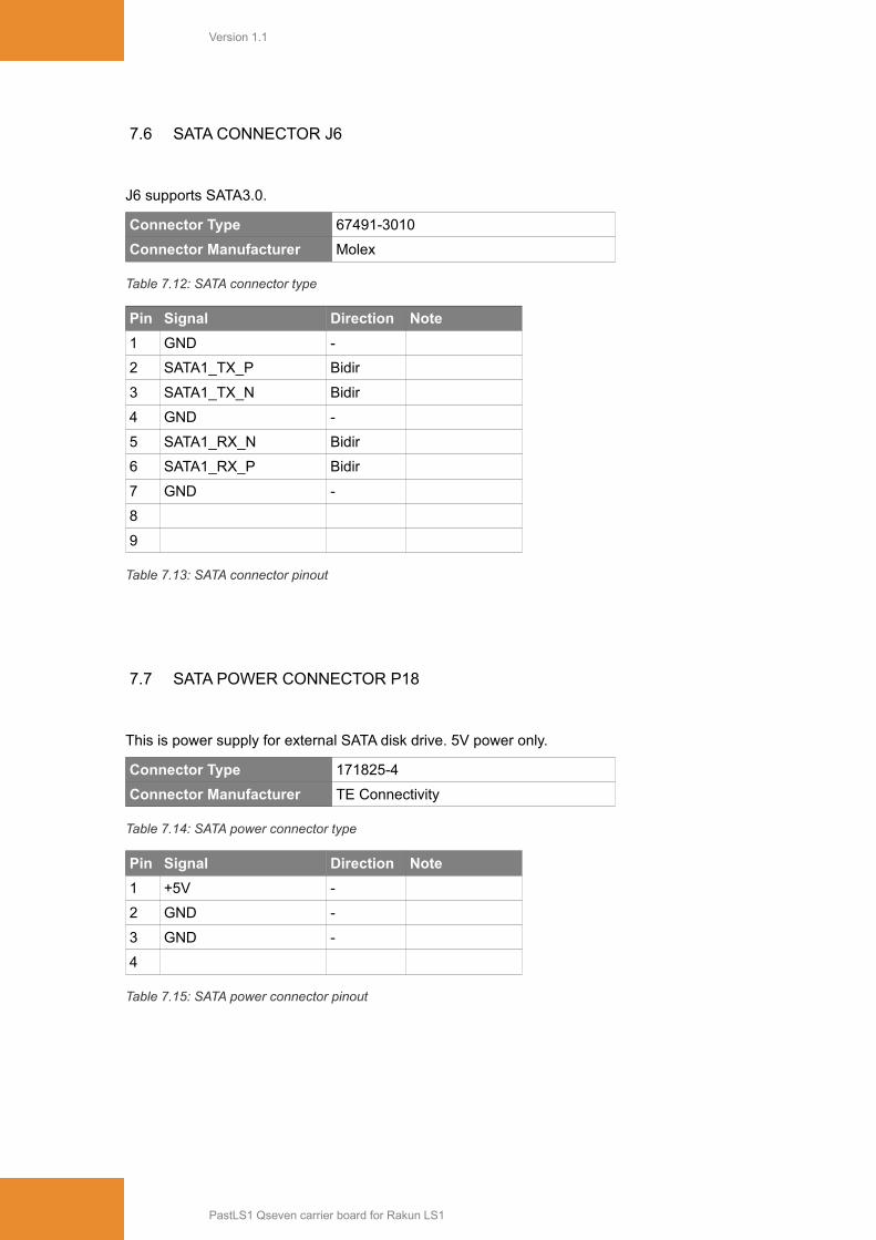
7.6 SATA CONNECTOR J6
J6 supports SATA3.0.
Connector Type 67491-3010
Connector Manufacturer Molex
Table 7.12: SATA connector type
Pin Signal Direction Note
1 GND -
2 SATA1_TX_P Bidir
3 SATA1_TX_N Bidir
4 GND -
5 SATA1_RX_N Bidir
6 SATA1_RX_P Bidir
7 GND -
8
9
Table 7.13: SATA connector pinout
7.7 SATA POWER CONNECTOR P18
This is power supply for external SATA disk drive. 5V power only.
Connector Type 171825-4
Connector Manufacturer TE Connectivity
Table 7.14: SATA power connector type
Pin Signal Direction Note
1 +5V -
2 GND -
3 GND -
4
Table 7.15: SATA power connector pinout
PastLS1 Qseven carrier board for Rakun LS1

Version 1.1
7.8 HDMI CONNECTOR P1
HDMI 1.3 connection.
Connector Type 685119134923
Connector Manufacturer Wurth Electronic
Table 7.16: HDMI connector type
Pin Signal Direction Note
1 TDMS_L2_P Out
2 GND -
3 TDMS_L2_N Out
4 TDMS_L1_P Out
5 GND -
6 TDMS_L1_N Out
7 TDMS_L0_P Out
8 GND -
9 TDMS_L0_N Out
10 TDMS_CLK_P Out
11 GND -
12 TDMS_CLK_P Out
13
14
15 HDMI_CTRL_CLK Out Pullup
16 HDMI_CTRL_DAT Bidir Pullup
17 GND -
18 +5V -
19 HDMI_HPD# In
Table 7.17: HDMI connector pinout
PastLS1 Qseven carrier board for Rakun LS1
Version 1.1
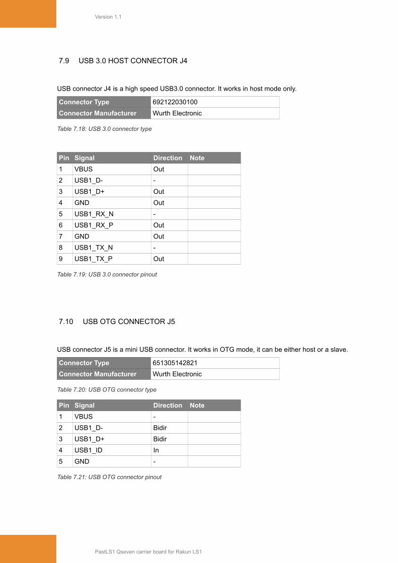
7.9 USB 3.0 HOST CONNECTOR J4
USB connector J4 is a high speed USB3.0 connector. It works in host mode only.
Connector Type 692122030100
Connector Manufacturer Wurth Electronic
Table 7.18: USB 3.0 connector type
Pin Signal Direction Note
1 VBUS Out
2 USB1_D- -
3 USB1_D+ Out
4 GND Out
5 USB1_RX_N -
6 USB1_RX_P Out
7 GND Out
8 USB1_TX_N -
9 USB1_TX_P Out
Table 7.19: USB 3.0 connector pinout
7.10 USB OTG CONNECTOR J5
USB connector J5 is a mini USB connector. It works in OTG mode, it can be either host or a slave.
Connector Type 651305142821
Connector Manufacturer Wurth Electronic
Table 7.20: USB OTG connector type
Pin Signal Direction Note
1 VBUS -
2 USB1_D- Bidir
3 USB1_D+ Bidir
4 USB1_ID In
5 GND -
Table 7.21: USB OTG connector pinout
PastLS1 Qseven carrier board for Rakun LS1
Version 1.1
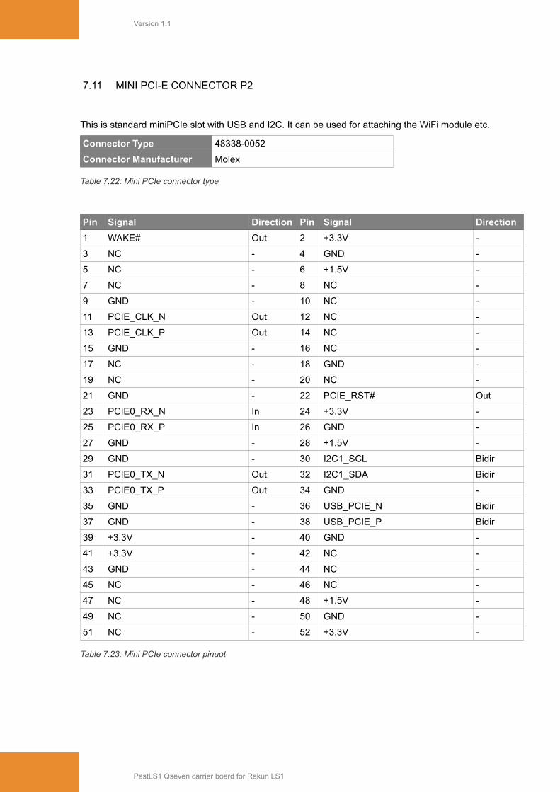
7.11 MINI PCI-E CONNECTOR P2
This is standard miniPCIe slot with USB and I2C. It can be used for attaching the WiFi module etc.
Connector Type 48338-0052
Connector Manufacturer Molex
Table 7.22: Mini PCIe connector type
Pin Signal Direction Pin Signal Direction
1 WAKE# Out 2 +3.3V -
3 NC - 4 GND -
5 NC - 6 +1.5V -
7 NC - 8 NC -
9 GND - 10 NC -
11 PCIE_CLK_N Out 12 NC -
13 PCIE_CLK_P Out 14 NC -
15 GND - 16 NC -
17 NC - 18 GND -
19 NC - 20 NC -
21 GND - 22 PCIE_RST# Out
23 PCIE0_RX_N In 24 +3.3V -
25 PCIE0_RX_P In 26 GND -
27 GND - 28 +1.5V -
29 GND - 30 I2C1_SCL Bidir
31 PCIE0_TX_N Out 32 I2C1_SDA Bidir
33 PCIE0_TX_P Out 34 GND -
35 GND - 36 USB_PCIE_N Bidir
37 GND - 38 USB_PCIE_P Bidir
39 +3.3V - 40 GND -
41 +3.3V - 42 NC -
43 GND - 44 NC -
45 NC - 46 NC -
47 NC - 48 +1.5V -
49 NC - 50 GND -
51 NC - 52 +3.3V -
Table 7.23: Mini PCIe connector pinuot
PastLS1 Qseven carrier board for Rakun LS1
Version 1.1
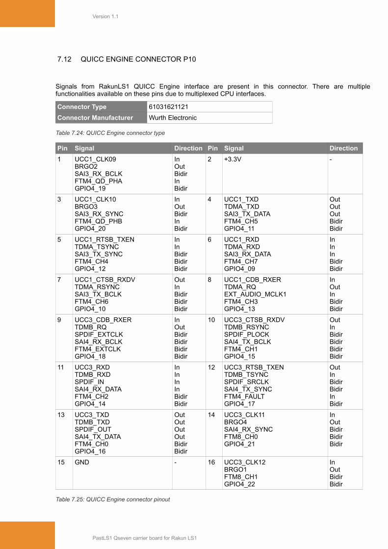
7.12 QUICC ENGINE CONNECTOR P10
Signals from RakunLS1 QUICC Engine interface are present in this connector. There are multiplefunctionalities available on these pins due to multiplexed CPU interfaces.
Connector Type 61031621121
Connector Manufacturer Wurth Electronic
Table 7.24: QUICC Engine connector type
Pin Signal Direction Pin Signal Direction
1 UCC1_CLK09BRGO2SAI3_RX_BCLKFTM4_QD_PHAGPIO4_19
InOutBidirInBidir
2 +3.3V -
3 UCC1_CLK10BRGO3SAI3_RX_SYNCFTM4_QD_PHBGPIO4_20
InOutBidirInBidir
4 UCC1_TXDTDMA_TXDSAI3_TX_DATAFTM4_CH5GPIO4_11
OutOutOutBidirBidir
5 UCC1_RTSB_TXENTDMA_TSYNCSAI3_TX_SYNCFTM4_CH4GPIO4_12
InInBidirBidirBidir
6 UCC1_RXDTDMA_RXDSAI3_RX_DATAFTM4_CH7GPIO4_09
InInInBidirBidir
7 UCC1_CTSB_RXDVTDMA_RSYNCSAI3_TX_BCLKFTM4_CH6GPIO4_10
OutInBidirBidirBidir
8 UCC1_CDB_RXERTDMA_RQEXT_AUDIO_MCLK1FTM4_CH3GPIO4_13
InOutInBidirBidir
9 UCC3_CDB_RXERTDMB_RQSPDIF_EXTCLKSAI4_RX_BCLKFTM4_EXTCLKGPIO4_18
InOutBidirBidirBidirBidir
10 UCC3_CTSB_RXDVTDMB_RSYNCSPDIF_PLOCKSAI4_TX_BCLKFTM4_CH1GPIO4_15
OutInBidirBidirBidirBidir
11 UCC3_RXDTDMB_RXDSPDIF_INSAI4_RX_DATAFTM4_CH2GPIO4_14
InInInInBidirBidir
12 UCC3_RTSB_TXENTDMB_TSYNCSPDIF_SRCLKSAI4_TX_SYNCFTM4_FAULTGPIO4_17
OutInBidirBidirInBidir
13 UCC3_TXDTDMB_TXDSPDIF_OUTSAI4_TX_DATAFTM4_CH0GPIO4_16
OutOutOutOutBidirBidir
14 UCC3_CLK11BRGO4SAI4_RX_SYNCFTM8_CH0GPIO4_21
InOutBidirBidirBidir
15 GND - 16 UCC3_CLK12BRGO1FTM8_CH1GPIO4_22
InOutBidirBidir
Table 7.25: QUICC Engine connector pinout
PastLS1 Qseven carrier board for Rakun LS1
Version 1.1
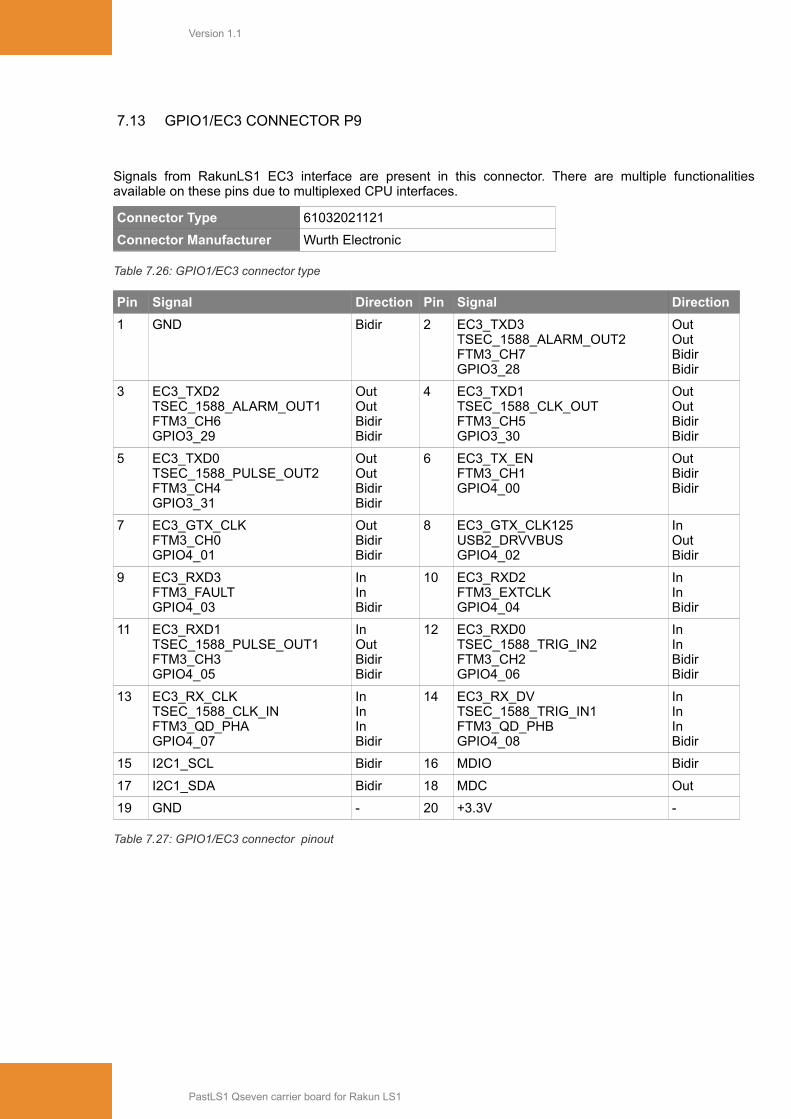
7.13 GPIO1/EC3 CONNECTOR P9
Signals from RakunLS1 EC3 interface are present in this connector. There are multiple functionalitiesavailable on these pins due to multiplexed CPU interfaces.
Connector Type 61032021121
Connector Manufacturer Wurth Electronic
Table 7.26: GPIO1/EC3 connector type
Pin Signal Direction Pin Signal Direction
1 GND Bidir 2 EC3_TXD3TSEC_1588_ALARM_OUT2FTM3_CH7GPIO3_28
OutOutBidirBidir
3 EC3_TXD2TSEC_1588_ALARM_OUT1FTM3_CH6GPIO3_29
OutOutBidirBidir
4 EC3_TXD1TSEC_1588_CLK_OUTFTM3_CH5GPIO3_30
OutOutBidirBidir
5 EC3_TXD0TSEC_1588_PULSE_OUT2FTM3_CH4GPIO3_31
OutOutBidirBidir
6 EC3_TX_ENFTM3_CH1GPIO4_00
OutBidirBidir
7 EC3_GTX_CLKFTM3_CH0GPIO4_01
OutBidirBidir
8 EC3_GTX_CLK125USB2_DRVVBUSGPIO4_02
InOutBidir
9 EC3_RXD3FTM3_FAULTGPIO4_03
InInBidir
10 EC3_RXD2FTM3_EXTCLKGPIO4_04
InInBidir
11 EC3_RXD1TSEC_1588_PULSE_OUT1FTM3_CH3GPIO4_05
InOutBidirBidir
12 EC3_RXD0TSEC_1588_TRIG_IN2FTM3_CH2GPIO4_06
InInBidirBidir
13 EC3_RX_CLKTSEC_1588_CLK_INFTM3_QD_PHAGPIO4_07
InInInBidir
14 EC3_RX_DVTSEC_1588_TRIG_IN1FTM3_QD_PHBGPIO4_08
InInInBidir
15 I2C1_SCL Bidir 16 MDIO Bidir
17 I2C1_SDA Bidir 18 MDC Out
19 GND - 20 +3.3V -
Table 7.27: GPIO1/EC3 connector pinout
PastLS1 Qseven carrier board for Rakun LS1
Version 1.1
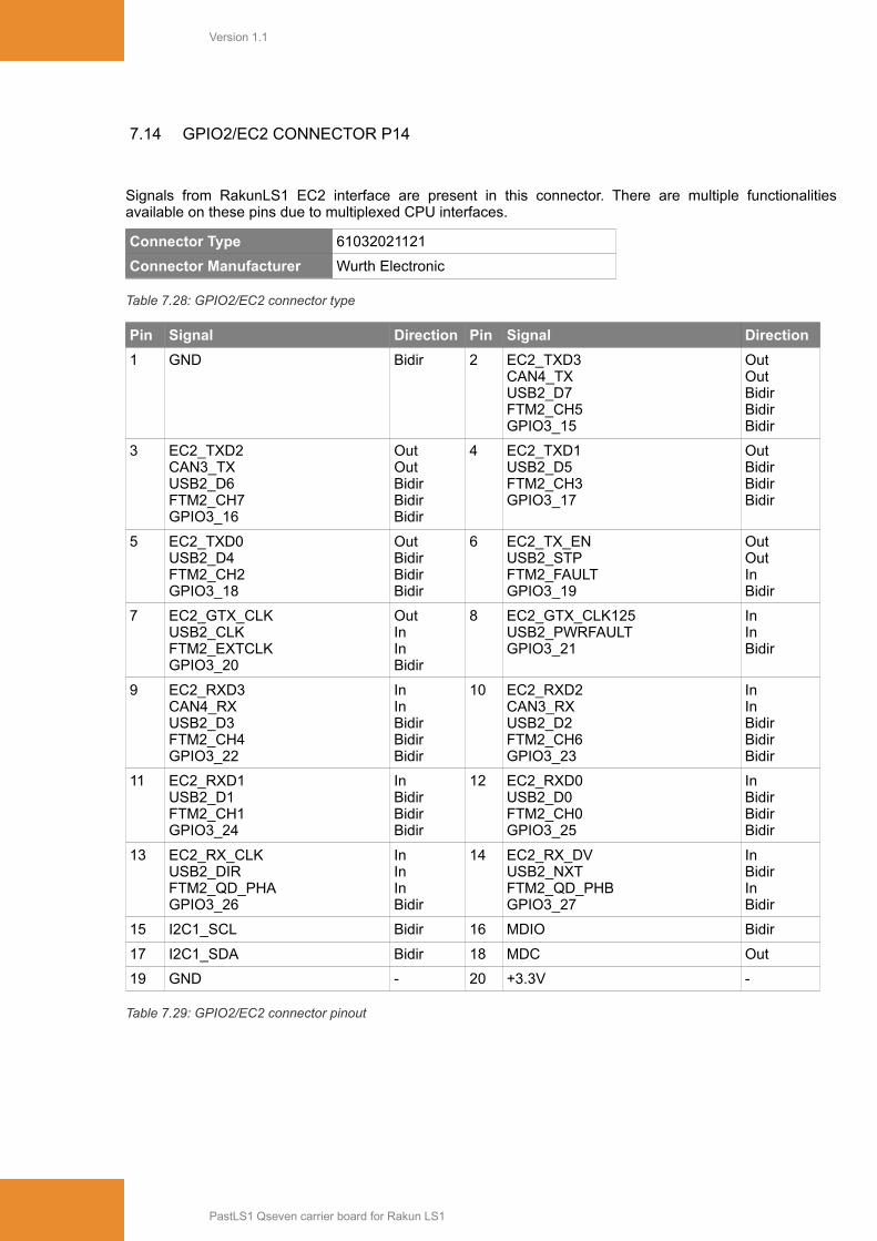
7.14 GPIO2/EC2 CONNECTOR P14
Signals from RakunLS1 EC2 interface are present in this connector. There are multiple functionalitiesavailable on these pins due to multiplexed CPU interfaces.
Connector Type 61032021121
Connector Manufacturer Wurth Electronic
Table 7.28: GPIO2/EC2 connector type
Pin Signal Direction Pin Signal Direction
1 GND Bidir 2 EC2_TXD3CAN4_TXUSB2_D7FTM2_CH5GPIO3_15
OutOutBidirBidirBidir
3 EC2_TXD2CAN3_TXUSB2_D6FTM2_CH7GPIO3_16
OutOutBidirBidirBidir
4 EC2_TXD1USB2_D5FTM2_CH3GPIO3_17
OutBidirBidirBidir
5 EC2_TXD0USB2_D4FTM2_CH2GPIO3_18
OutBidirBidirBidir
6 EC2_TX_ENUSB2_STPFTM2_FAULTGPIO3_19
OutOutInBidir
7 EC2_GTX_CLKUSB2_CLKFTM2_EXTCLKGPIO3_20
OutInInBidir
8 EC2_GTX_CLK125USB2_PWRFAULTGPIO3_21
InInBidir
9 EC2_RXD3CAN4_RXUSB2_D3FTM2_CH4GPIO3_22
InInBidirBidirBidir
10 EC2_RXD2CAN3_RXUSB2_D2FTM2_CH6GPIO3_23
InInBidirBidirBidir
11 EC2_RXD1USB2_D1FTM2_CH1GPIO3_24
InBidirBidirBidir
12 EC2_RXD0USB2_D0FTM2_CH0GPIO3_25
InBidirBidirBidir
13 EC2_RX_CLKUSB2_DIRFTM2_QD_PHAGPIO3_26
InInInBidir
14 EC2_RX_DVUSB2_NXTFTM2_QD_PHBGPIO3_27
InBidirInBidir
15 I2C1_SCL Bidir 16 MDIO Bidir
17 I2C1_SDA Bidir 18 MDC Out
19 GND - 20 +3.3V -
Table 7.29: GPIO2/EC2 connector pinout
PastLS1 Qseven carrier board for Rakun LS1

Version 1.1
7.15 MIKROBUS CONNECTOR P4+P5
MikroBUS slot can be used for attaching number of mikroBUS compatible add-on boards. For moreinformation, see Appendix B.
Connector Type 2x 61300811821
Connector Manufacturer Wurth Electronic
Table 7.30: Microbus connector type
P4 P5
Pin Signal Direction Pin Signal Direction
1 UBUS_AN In 1 UBUS_PWM (GPIO3_25) In
2 UBUS_RST (GPIO3_24) Out 2 UBUS_INT (GPIO3_22) In
3 SPI_CS0 Out 3 UART4_RX In
4 SPI_CLK Out 4 UART4_TX Out
5 SPI_MISO In 5 I2C1_SCL Bidir
6 SPI_MOSI Out 6 I2C1_SDA Bidir
7 +3.3V - 7 +5V -
8 GND - 8 GND -
Table 7.31: Microbus connector pinout
7.16 UART CONNECTOR P6
Four UARTs are present on this connector. Two of them (UART1, UART2) can be routed to the USB2UARTconverter FT230Q.
Connector Type 61031021121
Connector Manufacturer Wurth Electronic
Table 7.32: UART connector type
Pin Signal Direction Note
1 UART1_SIN In Pullup
2 UART2_SIN In Pullup
3 UART1_SOUT Out
4 UART2_SOUT Out
5 GND -
6 GND -
7 UART1_RTS# (UART3_SOUT) Out
8 UART2_RTS# (UART4_SOUT) Out
9 UART1_CTS# (UART3_SIN) In Pullup
10 UART2_CTS# (UART4_SIN) In Pullup
Table 7.33: UART connector pinout
PastLS1 Qseven carrier board for Rakun LS1
Version 1.1
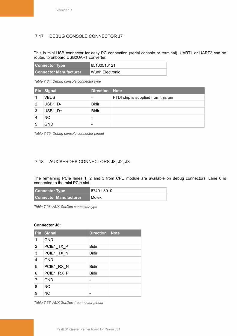
7.17 DEBUG CONSOLE CONNECTOR J7
This is mini USB connector for easy PC connection (serial console or terminal). UART1 or UART2 can berouted to onboard USB2UART converter.
Connector Type 65100516121
Connector Manufacturer Wurth Electronic
Table 7.34: Debug console connector type
Pin Signal Direction Note
1 VBUS - FTDI chip is supplied from this pin
2 USB1_D- Bidir
3 USB1_D+ Bidir
4 NC -
5 GND -
Table 7.35: Debug console connector pinout
7.18 AUX SERDES CONNECTORS J8, J2, J3
The remaining PCIe lanes 1, 2 and 3 from CPU module are available on debug connectors. Lane 0 isconnected to the mini PCIe slot.
Connector Type 67491-3010
Connector Manufacturer Molex
Table 7.36: AUX SerDes connector type
Connector J8:
Pin Signal Direction Note
1 GND -
2 PCIE1_TX_P Bidir
3 PCIE1_TX_N Bidir
4 GND -
5 PCIE1_RX_N Bidir
6 PCIE1_RX_P Bidir
7 GND -
8 NC -
9 NC -
Table 7.37: AUX SerDes 1 connector pinout
PastLS1 Qseven carrier board for Rakun LS1
Version 1.1
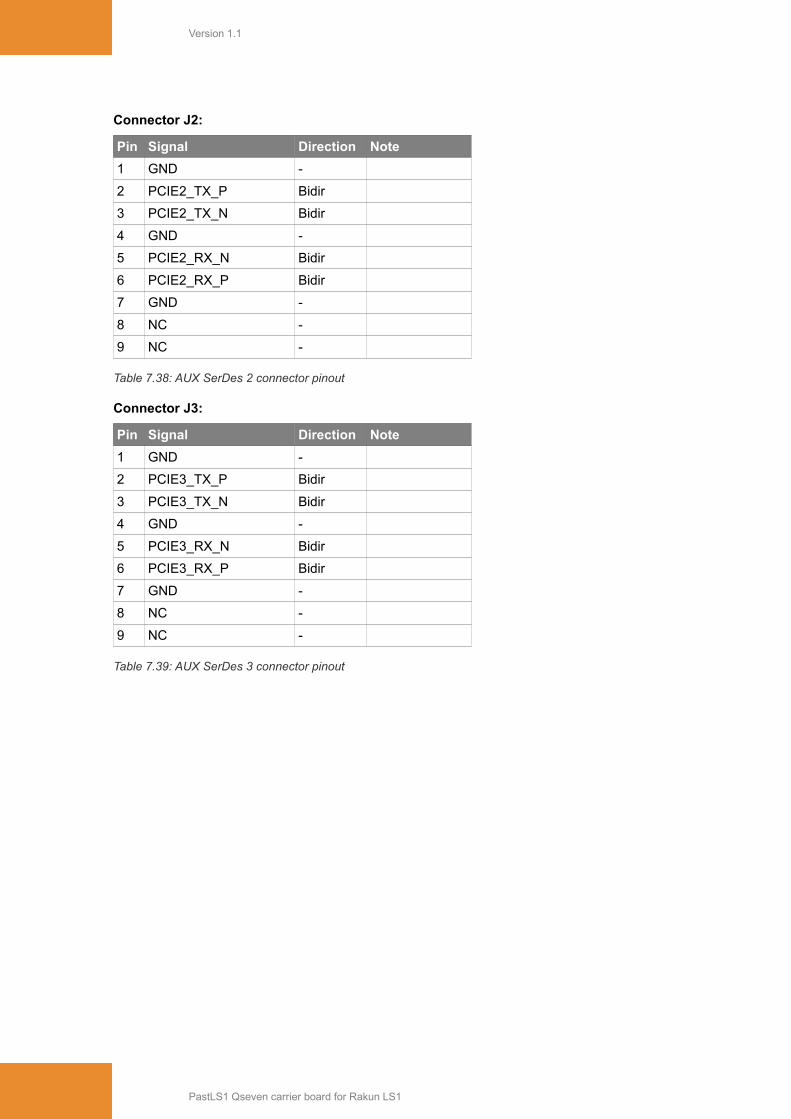
Connector J2:
Pin Signal Direction Note
1 GND -
2 PCIE2_TX_P Bidir
3 PCIE2_TX_N Bidir
4 GND -
5 PCIE2_RX_N Bidir
6 PCIE2_RX_P Bidir
7 GND -
8 NC -
9 NC -
Table 7.38: AUX SerDes 2 connector pinout
Connector J3:
Pin Signal Direction Note
1 GND -
2 PCIE3_TX_P Bidir
3 PCIE3_TX_N Bidir
4 GND -
5 PCIE3_RX_N Bidir
6 PCIE3_RX_P Bidir
7 GND -
8 NC -
9 NC -
Table 7.39: AUX SerDes 3 connector pinout
PastLS1 Qseven carrier board for Rakun LS1
Version 1.1
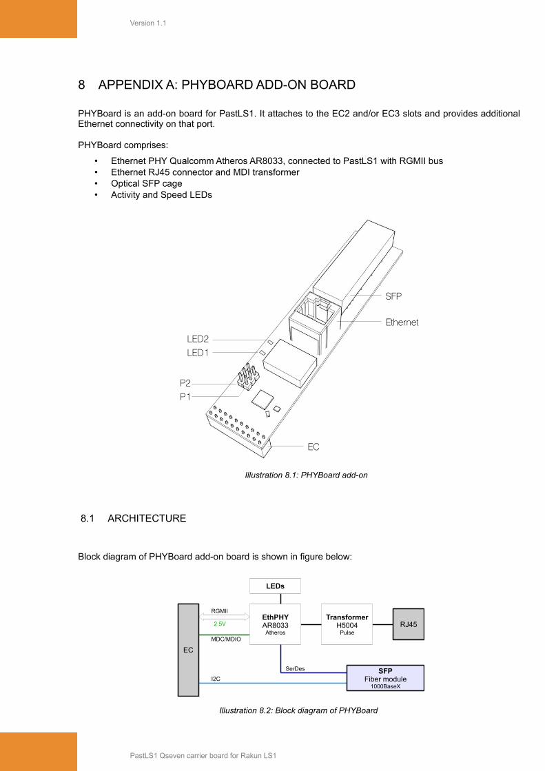
8 APPENDIX A: PHYBOARD ADD-ON BOARD
PHYBoard is an add-on board for PastLS1. It attaches to the EC2 and/or EC3 slots and provides additionalEthernet connectivity on that port.
PHYBoard comprises:
• Ethernet PHY Qualcomm Atheros AR8033, connected to PastLS1 with RGMII bus• Ethernet RJ45 connector and MDI transformer• Optical SFP cage• Activity and Speed LEDs
Illustration 8.1: PHYBoard add-on
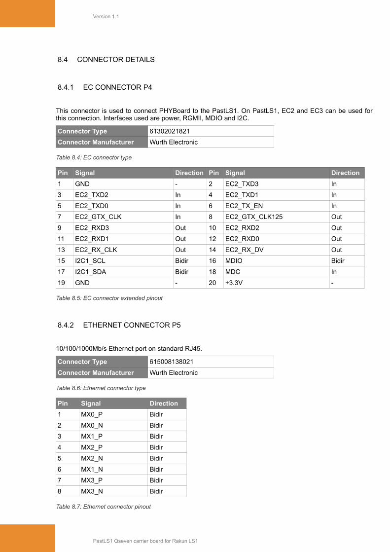
8.1 ARCHITECTURE
Block diagram of PHYBoard add-on board is shown in figure below:
Illustration 8.2: Block diagram of PHYBoard
PastLS1 Qseven carrier board for Rakun LS1
P1P2
EC
Ethernet
SFP
LED1LED2
MDC/MDIO
RGMII
2.5V
SFPFiber module
1000BaseX
EthPHYAR8033Atheros
RJ45Transformer
H5004Pulse
I2C
SerDes
EC
LEDs

Version 1.1
8.2 JUMPERS
8.2.1 ETHERNET MODE JUMPER P1
Mode jumper selects mode of operation for Ethernet PHY. Mode of operation can be Copper Ethernet(connector P5) or Fiber Ethernet (SFP cage).
Jumpers P1 is 3-pin jumper.
P1
Setting Function
1 – 2 Fiber interface
2 – 3 Copper interface (Default jumpers placement)
Table 8.1: Ethernet mode selection jumper P1
8.2.2 ADDRESS JUMPER P2
Jumpers P16 and P17 select the UART interface that is connected to the UART to USB converter FT230.This device provides serial console on USB connector J7 for easy connection to the PC. Jumpers P16 andP17 must always be set up in the same way.
Jumpers P16 and P17 are 3-pin jumpers.
P2
Setting Function
1 – 2 UART1 is used for serial console
2 – 3 UART2 is used for serial console (Default jumpers placement)
Table 8.2: UART to USB selection jumpers P16 and P17
8.3 LED INDICATORS
Board comprises 2 LED indicators. Default behavior of LEDs are as follows
LED Signal Meaning
LED1 (white) LINK1000# OFF: Speed 10/100Mb/s (also no link)ON: Link established, speed 1000Mb/s
LED2 (white) ACT# OFF: no linkON: link upBlink: traffic
Table 8.3: Ethernet LEDs
PastLS1 Qseven carrier board for Rakun LS1
Version 1.1
8.4 CONNECTOR DETAILS
8.4.1 EC CONNECTOR P4
This connector is used to connect PHYBoard to the PastLS1. On PastLS1, EC2 and EC3 can be used forthis connection. Interfaces used are power, RGMII, MDIO and I2C.
Connector Type 61302021821
Connector Manufacturer Wurth Electronic
Table 8.4: EC connector type
Pin Signal Direction Pin Signal Direction
1 GND - 2 EC2_TXD3 In
3 EC2_TXD2 In 4 EC2_TXD1 In
5 EC2_TXD0 In 6 EC2_TX_EN In
7 EC2_GTX_CLK In 8 EC2_GTX_CLK125 Out
9 EC2_RXD3 Out 10 EC2_RXD2 Out
11 EC2_RXD1 Out 12 EC2_RXD0 Out
13 EC2_RX_CLK Out 14 EC2_RX_DV Out
15 I2C1_SCL Bidir 16 MDIO Bidir
17 I2C1_SDA Bidir 18 MDC In
19 GND - 20 +3.3V -
Table 8.5: EC connector extended pinout
8.4.2 ETHERNET CONNECTOR P5
10/100/1000Mb/s Ethernet port on standard RJ45.
Connector Type 615008138021
Connector Manufacturer Wurth Electronic
Table 8.6: Ethernet connector type
Pin Signal Direction
1 MX0_P Bidir
2 MX0_N Bidir
3 MX1_P Bidir
4 MX2_P Bidir
5 MX2_N Bidir
6 MX1_N Bidir
7 MX3_P Bidir
8 MX3_N Bidir
Table 8.7: Ethernet connector pinout
PastLS1 Qseven carrier board for Rakun LS1
Version 1.1
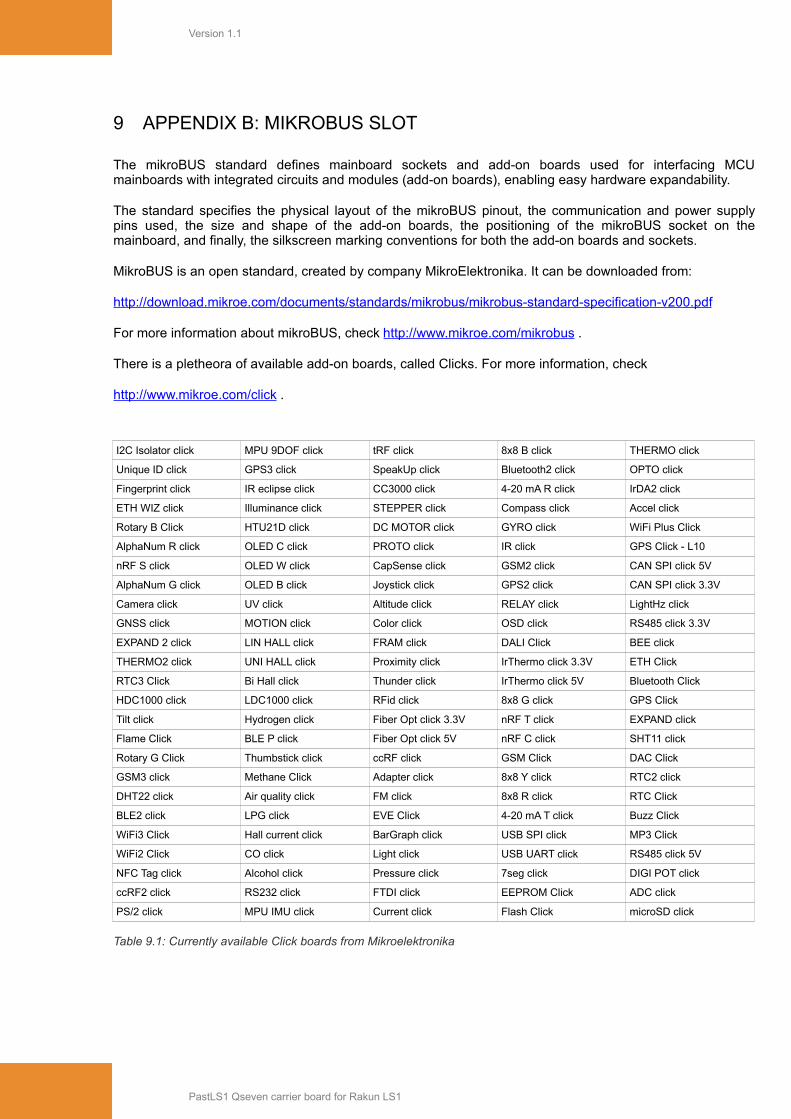
9 APPENDIX B: MIKROBUS SLOT
The mikroBUS standard defines mainboard sockets and add-on boards used for interfacing MCUmainboards with integrated circuits and modules (add-on boards), enabling easy hardware expandability.
The standard specifies the physical layout of the mikroBUS pinout, the communication and power supplypins used, the size and shape of the add-on boards, the positioning of the mikroBUS socket on themainboard, and finally, the silkscreen marking conventions for both the add-on boards and sockets.
MikroBUS is an open standard, created by company MikroElektronika. It can be downloaded from:
http://download.mikroe.com/documents/standards/mikrobus/mikrobus-standard-specification-v200.pdf
For more information about mikroBUS, check http://www.mikroe.com/mikrobus .
There is a pletheora of available add-on boards, called Clicks. For more information, check
http://www.mikroe.com/click .
I2C Isolator click MPU 9DOF click tRF click 8x8 B click THERMO click
Unique ID click GPS3 click SpeakUp click Bluetooth2 click OPTO click
Fingerprint click IR eclipse click CC3000 click 4-20 mA R click IrDA2 click
ETH WIZ click Illuminance click STEPPER click Compass click Accel click
Rotary B Click HTU21D click DC MOTOR click GYRO click WiFi Plus Click
AlphaNum R click OLED C click PROTO click IR click GPS Click - L10
nRF S click OLED W click CapSense click GSM2 click CAN SPI click 5V
AlphaNum G click OLED B click Joystick click GPS2 click CAN SPI click 3.3V
Camera click UV click Altitude click RELAY click LightHz click
GNSS click MOTION click Color click OSD click RS485 click 3.3V
EXPAND 2 click LIN HALL click FRAM click DALI Click BEE click
THERMO2 click UNI HALL click Proximity click IrThermo click 3.3V ETH Click
RTC3 Click Bi Hall click Thunder click IrThermo click 5V Bluetooth Click
HDC1000 click LDC1000 click RFid click 8x8 G click GPS Click
Tilt click Hydrogen click Fiber Opt click 3.3V nRF T click EXPAND click
Flame Click BLE P click Fiber Opt click 5V nRF C click SHT11 click
Rotary G Click Thumbstick click ccRF click GSM Click DAC Click
GSM3 click Methane Click Adapter click 8x8 Y click RTC2 click
DHT22 click Air quality click FM click 8x8 R click RTC Click
BLE2 click LPG click EVE Click 4-20 mA T click Buzz Click
WiFi3 Click Hall current click BarGraph click USB SPI click MP3 Click
WiFi2 Click CO click Light click USB UART click RS485 click 5V
NFC Tag click Alcohol click Pressure click 7seg click DIGI POT click
ccRF2 click RS232 click FTDI click EEPROM Click ADC click
PS/2 click MPU IMU click Current click Flash Click microSD click
Table 9.1: Currently available Click boards from Mikroelektronika
PastLS1 Qseven carrier board for Rakun LS1

Version 1.1
PastLS1 Qseven carrier board for Rakun LS1