Past and Future of Geotechnical Earthquake...
20
Past and Future of Geotechnical Earthquake Engineering* INTRODUCTION by Shamsher Prakash** Earthquakes have occurred ever since Mother Earth came into existence. Man had learnt to build earthquake-proof houses by intuition. Timber is more resilientthan masonry and cnncrete and it can sustain large deformations without failure. Therefore, earlier constructions were made in wood framework in-filled with masonry. For one and two-storyed houses in the hills, this is still a prevalent practice in India. However, as the demand on high-rise and massive buildings increased due to industrialization in the West and lack of space, particularly in metropolitan areas, the enormity of the problems increased manifold. Potentially hazardous installations like nuclear power houses are sited in active seismic zones. The risk of loss of human life has increased manifold. This requires rather precise understanding of the behaviour of the foundation and soils under dynamic loads. The progress in geotechnical earthquake engineering has lagged behind its counterpart field of structural dynamics firstly because of the fact that it was erroneously believed that in poor soils, strengthening the superstructure would be enough. The tilting of buildings by as much as goo in the Niigata earthquake of 1964 and floating up of the hollow substructures like septic tanks exploded this myth (Prakash, 1981 a). Secondly, several important aspects of dynamic behaviour of soils have been understood only recently (1983). Also, in most structural analyses, as of today (1983), the foundation is regarded as either resting on rigid material so that the deformations in the soil to not take place or the soil is represented by an elastic spring at best. This makes the analysis simple, but the question is how far such assumptions are true and the extent to which we can predict the soil behaviour. In this paper, a few important problems of geotechnical earthquake engineering are examined in relation to the solution technique in the past and needed work in the future. RATIONAL EVALUATION OF DYNAMIC SOIL PROPERTIES Major soil properties that need to be determined for solving problems in geotechnical earthquake engineering are (Prakash, 1981 a) : 1. dynamic soil moduli, young's modulus, shear modulus, bulk modulus, and constrained modulus. 2. shear strength evaluated in terms of strain rates and stress-strain characteristics, 3. damping, 4. poission's ratio, and 5. liquefaction parameters: cyclic shearing stress ratio, cyclic deformation, and pore-pressure response. Dynamic moduli depend upon several variables and techniques for their determination have been perfected independently in several countries, e.g., wave propagation tests in the U.S. and Japan, and footing vibration tests and cyclic plate load tests in USSR (Barkan, 1962) and in India (Prakash and Puri, 1981 b). More important vatiables which affect the dynamic soil moduli are: 1. type of soil and its simple properties (e.g., state of disturbance), 2. initial static sustained stress level or effective confining pressure, 3. sliear strain level, 4. time effects, *Sixth IGS Annual Lecture delivered on the occasion of its 25th Annual General Session held at Madras, India. Dec , 1993 **Director, Central Building Research Institute, Roorkee (U.P.) Formerly Professor and Head, Civil Engineenng Department, University of Roorkee, Roorkee, India, and Professor in Civil Engineering, University of Missouri-Rolla, Rolla, Missoun. 181
Transcript of Past and Future of Geotechnical Earthquake...

Past and Future of Geotechnical Earthquake Engineering*
INTRODUCTION
by
Shamsher Prakash**
Earthquakes have occurred ever since Mother Earth came into existence. Man had learnt to build earthquake-proof houses by intuition. Timber is more resilientthan masonry and cnncrete and it can sustain large deformations without failure. Therefore, earlier constructions were made in wood framework in-filled with masonry. For one and two-storyed houses in the hills, this is still a prevalent practice in India. However, as the demand on high-rise and massive buildings increased due to industrialization in the West and lack of space, particularly in metropolitan areas, the enormity of the problems increased manifold. Potentially hazardous installations like nuclear power houses are sited in active seismic zones. The risk of loss of human life has increased manifold. This requires rather precise understanding of the behaviour of the foundation and soils under dynamic loads.
The progress in geotechnical earthquake engineering has lagged behind its counterpart field of structural dynamics firstly because of the fact that it was erroneously believed that in poor soils, strengthening the superstructure would be enough. The tilting of buildings by as much as goo in the Niigata earthquake of 1964 and floating up of the hollow substructures like septic tanks exploded this myth (Prakash, 1981 a). Secondly, several important aspects of dynamic behaviour of soils have been understood only recently (1983). Also, in most structural analyses, as of today (1983), the foundation is regarded as either resting on rigid material so that the deformations in the soil to not take place or the soil is represented by an elastic spring at best. This makes the analysis simple, but the question is how far such assumptions are true and the extent to which we can predict the soil behaviour.
In this paper, a few important problems of geotechnical earthquake engineering are examined in relation to the solution technique in the past and needed work in the future.
RATIONAL EVALUATION OF DYNAMIC SOIL PROPERTIES Major soil properties that need to be determined for solving problems in geotechnical earthquake
engineering are (Prakash, 1981 a) :
1. dynamic soil moduli, young's modulus, shear modulus, bulk modulus, and constrained modulus.
2. shear strength evaluated in terms of strain rates and stress-strain characteristics,
3. damping,
4. poission's ratio, and
5. liquefaction parameters: cyclic shearing stress ratio, cyclic deformation, and pore-pressure response.
Dynamic moduli depend upon several variables and techniques for their determination have been perfected independently in several countries, e.g., wave propagation tests in the U.S. and Japan, and footing vibration tests and cyclic plate load tests in USSR (Barkan, 1962) and in India (Prakash and Puri, 1981 b). More important vatiables which affect the dynamic soil moduli are:
1. type of soil and its simple properties (e.g., state of disturbance),
2. initial static sustained stress level or effective confining pressure,
3. sliear strain level,
4. time effects,
*Sixth IGS Annual Lecture delivered on the occasion of its 25th Annual General Session held at Madras, India. Dec , 1993
**Director, Central Building Research Institute, Roorkee (U.P.) Formerly Professor and Head, Civil Engineenng Department, University of Roorkee, Roorkee, India, and Professor in Civil Engineering, University of Missouri-Rolla, Rolla, Missoun.
181

5. overconsolidation ratio,
6. dynamic stress level,
7. number of repetitions of dynamic stress, and
8. degree of saturation.
There are severallaboratorv and field tests to determine dynamic moduli. Laboratory tests most often used are (i) resonant column, (ii) cyclic triaxial, (iii) cyclic simple shear, (iv) cyclic torsional shear and (v) shake table tests. Popular field methods are (i) cross- borehole wave propagation test, (ii) up-hole or down-hole wave propagation test, (iii) surface wave propagation test,(iv) vertical footing resonance test, (v) horizontal footing resonance test, (vi) free vibration test on footing, (vii) cyclic plate load test, and (viii) standard penetration test. For test details, reference may be made to Prakash (1981a), Prakash and Puri (1984), and Woods (1978). Different types of tests are performed at different strain levels and effective confining pressures. Figure I shows strain levels associated with different physical phenomena, in-situ and laboratory measurements (Ishihara, 1971).
Therefore, the numerical results obtained from each one ofthese tests will have to be "normalized" before these can be compared.
Several relationships have been proposed between maximum value of shear modulus (GmaJ and the variables listed above. Comprehensive reviews have been prepared by Richart (1977), Prakash (1981 a), and Prakash and Puri (1984). Hardin and Black (1969) expressed Gmax (psi) as follows:
Gmax : 1230 OCRK (2. 973- e)2 (1 +e)
Magnitude of strain 1Q•6 1 o-s I I
Phenomena Wave propagation, vibration
Mechanical Elastic characteristics
1Q-4 1Q-3
I Cracks, differential
settlement
Elastic plastic
Constants Shear modulus, Poisson's ratio, damping ratio
Seismic wave
In-situ method
measur- In-situ
ement vibration test
Repeated loading test
Wave propa-gation test
Laboratory Resonant
measure- column test ment
Repeated loading test
... (1 )
1 o-2 1Q-1
I Slide, compaction,
liquefaction
Failure
Angle of internal friction, cohesion
Figure 1 Strain level associated with different in-situ and laboratory tests (After Ishihara, 1971).
in which OCR = overconsolidation ratio,
00 = effective confining pressure, psi
e = void ratio, and
k = a factor that depends upon the plasticity index of clays.
Hardin (1978) recommended that this equation be used for the anisotropic state of stress by taking oo =(a, +o
2 +cr
3)/3, the mean effective principle stress. The parameter k, given in Table 1, is related to the plasticity
index.
182

2400
o FORCED VIBRATION TEST A FREE VIBRATION TESTS tJ CYCLIC PLATE LOAD TEST
' • SHEAR MODULUS TEST
l (.) -... Ol ~
CJ OJ U)
w ::J ::J
" 0 ~ (ij Q) .c (/) (.) .E <1l c >-0
2000
};---r---r--~ ---- -..... r--.. ( ' 1 ;:----- r-- ~ I 6 ---
~/ ! & -~ ;>-..:: ~ ~
p6
~" 0 6 ~ 'o.t
'~'-6~ ~i ~ -- ~--- 01 "I'\ K - 6o
~ ~
~ t;.7 &o
~ ~~~~ ~ •l .,
" ~) 07 k f'.r-...~ ~ 1
07 07 ~ t'1-tJ
pi' oa 7,.,. 7( ~~! I r- r----
7 ~ I 1 17~5 -~ 7
~~ r---:: ~ ffJ~ I
l::--Jc1,;.~ ot 5 'f } ~~ ~-"'¥-1'1111::::
~;L uu o/ ~ i 6 !i" 2 l. 4 4
Gf i 2 2. 6 6 r"tl
1600
1200
BOO
40
10-6 10-5 10-4 10-3 10-2 ·10-1
Shear strain amplitude
FIGURE 2 Dynamic shear modulus vs. strain (After Prakash & Puri,1980 Prakash 1981

Plasticity Index,%
(For clayey soils)
0
20
40
60
80
100
For sands.
TABLE 1
VALUES OF k
k
0
0.18
0.30
0.41
0.48
0.50
0
The effect of strain on the soil modulus has been studied by Seed and ldriss (1970) through laboratory tests and Prakash and Puri (1981 b) through different types of in-situ tests. Figure 2 shows typical variation of shear modulus (G) versus shear strain (y) for seven sites spread over the country. The strain level variation was 1 o-s to 1 o-,. For site 6, the G was 1925 kg/cm2 and the smallest value was about 200 kg/cm2
, a ten times max reduction in modulus with strain. Figure 3 shows a non-dimensional plots of G/Gmax versus shear strain (Prakash, 1981 a) for the same test sites as in Figure 2. The corresponding plots of laboratory tests of Seed and ldriss (1970) are also shown. The range of scatter in the plots is considerably reduced as compared to that in Fig. 2. In fact Gmax can be estimated rather easily by Eq. 1 or similar other expression (Prakash and Puri, 1984). By selecting an appropriate normalized plot in Fig.3, a complete G versus y plot is obtained.
1.2
1.0 RANGE FOR SANDS [SEED & IDRISS (1970)1 N SITE No.
0.6
0.6 < ~
E ~ a 0.4
0.2
0
10-6 10-5 10-4 10-3. 10-2 10-1
Dynamic Shear Strain
FIGURE 3 Normalized shear modulus (G/Gmax) vs. shear strain (After Prakash and Puri, 1981 b)
Sampling of saturated sands is a difficult task. Therefore, field testing has been emphasized in such cases. Cross-bore hole tests, up and down hole tests which are low strain tests, are frequently used in the United States. The footing vibration test is an intermediate strain level test and a cyclic plate load test is a large strain test. The latter is astatictest.lnsoils in which values of soil moduli are not dependent on the rate of loading, cyclic plate load tests may be used for determination of properties for dynamic loading conditions. In this manner, a complete curve of G versus y can be obtained by combining data of different types of in-situ tests. Scatter in field test data is unavoidable and may be due to local variation of soil conditions. This is ari added advantage of field tests since the or.der of deviation from the average also becomes known to the designer. Assumptions in interpretation model and experimental errors also contribute to scatter of data, (Prakash, 1981 c). ·
184

o = constant. 0
y < 10"3 %
G1000
A G
PRIMARY CONSOLIDATION
Ia N --·--
G G1000
LOG-TERM TIME EFFECT
Duration of confinement ( Log scale)
FIGURE 4 Phases of modulus-time response (After Anderson and Stokoe-1977)
It is also interesting to see that shear strain yin plate loading tests on soils is nearly equal to vertical strain E and may be defined as (Prakash and Puri, 1981 b)
y = elastic vertical deformation or settlement
width of plate or footing ... (2)
Extensive field data from six sites in India has been analyzed and reported by Prakash and Puri (1981 b).
There are several field loading conditions in which preCise meaning of strain is not known. In a laterally loaded pile, and a retaining wall undergoir.g vibrations during an earthquake, shear strain at a point can be computed by rigorous stress analysis methods i.e., finite element and then strain may be averaged for any given length of soil mass behind the structure. But this is no consolation to the field engineer. Also in wave propagation tests, it is arbitrarily assumed that the strain level is small and is of the order of 1 o-s to 1 o-s.
It is customary to make a plot of G versus shear strain. It is necessary to determine G at a standard reference pressure. Prakash (1981 a) and Prakash and Puri (1981 b) recommended that a mean confining pressure, o
01 of 1000 KN/m2 be used to compute G values from the measure G values at confining pressures of
0 02 - Eq. (3) may be used, 1-DAY 1-WFEK 1o-weeKs
SOILS NG %
NC CLAYS .5-20 OC CLAYS 3-10
CLEAN SANDS <1-3
SANDS
b. G-
1 I I
I A G I I I I I
0~------~------~~-----L--------L~----_J -10 10'2 .103 105
Duration of confinement ( m1n )
FIGURE 5 Effect of confinement time on shear modulus (after Anderson and Stockoe 1977)
185

where
and
TIME EFFECTS
(- )0.5 oo1 --002
v . --0 1 - V :._ X
... (3)
... (4)
. .. (5)
The effect of duration of confinement at a constant pressure on the magnitude of shear moduli was reported first by Richart (1961). It was observed later that when specimens were confined at a constant confining pressure, shear moduli measured at shearing strain amplitudes below 0.001 per cent (commonly referred to as low amplitude moduli at a strain of 1 o·s or less) increased with the time of the specimen's confinement. These studies show that shear moduli of artificially prepared soil specimens ifldeed increase with the length of time a specimen is confined. More recently, sustained-pressure studies on undisturbed specimens of sands and clays have shown that similar time-dependent behaviour is also characteristic of natural soils (Anderson and Stokoe,1977).
For most soils the time-dependent behaviour at low strain levels can be characterized by an initial phase when a modulus changes rapidly with time. This is followed by a second phase when a modulus increases almost linearly with the logarithm of .the time, Fig. 4. For the most part, the initial phase results from void ratio changes during primary consolidation and is, therefore, referred to as "primary consolidation". The second phase, in which a modulus increases almost linearly with the logarithm of til ne is believed to result largely from a strengthening of the physico-chemical bonds in the case of cohesive soils and an increase in particle contact for cohesion less soils. This phase is referred to as the "long-term time effect." The long term effect represents the increase in the modulus with time that occurs after primary consolidation is completed.
Two methods are used to describe the long-term effect. The long-term time effect is expressed in an absolute sense as a coefficient of shear modulus incr:ease with time, IG. That is,
..... (6)
where
t, .~ =the times after primary consolidation, and
~G = change in low-amplitude shear modulus from t, to t2
•
Numerically, IG equals the value of G for one logarithmic cycle of time. The long-term effect is also expressed in relative terms by the normalized shear modulus increase with time, NG. That is,
where
=_h 100% Gwoo ... (7)
G, 000 is the shear modulus measured after 1 000 minutes of constant confining pressure after completion of the primary consolidation.
The duration of primary consolidation and the magnitude of the long-term time effect vary with such factors as soil type, initial void ratio, undrained shearing strength, confining pressure, and stress history. Figure 5 shows typical time-dependent modulus responses for different soils. Typical values of IG and NG are given in Table 2.
It should be noted that the modulus values determined at a time before the end of the primary consolidation is complete, are at an effective stress less than that assumed, because excess pore-water
186

pressures still exist in the specimen.
In Fig.5, it can be seen that the shape of the modulus-time response for the cohesionless soil differs significantly from that of the fine-grained soils. For the sand, the primary consolidation phase is not evident. Rather, the long-term time effect had begun by the time the first measurement was m~de. The long-term time effect is, however, similar to that which occurs for clays. For a typical sand, the values of IG and NG were found as 1725 KN/m2 and 1 .0 per cent, respectively (Anderson and Stokoe, 1977). These values are much smaller than those for the clays.
TABLE2
TYPICAL VALUES OF IG AND NG (AFTER ANDERSON AND STOKOE, 1977)
Soil Type Specimen Type Confining Low Amplitude TyplcaiiG Typical N0 Pressure Shear Modulus (kN/m2) (%) (kN/m2) 1000(kN/m2)
1 2 3 4 5 6
EPK Kaolinite vacuum extruded 200-300 140,000-190,000 24,000-35,000 17-18. Ottawa sand compacted by 70-280 50,000-180,000 1400-5500 1-11 Quartz sand raining and Quartz silt tamping Dry clay
Kaolinite vacuum extruded 70-550 4000-170,000 1000-8500 5-25 Bentonite
Agsco sand compacted by 70-280 50,000-110,000 2000-10,000 1-17 Ottawa sand raining and tamping Air-dried EPK Kaolinite
Saturated EPK vacuum extruded Kaolinite
Silty sand undisturbed 70-220 80,000-2,600,000 2000-22,900 1-14 Sandy silt Clayey silt Shale
Boston blue clay undisturbed 70-700 32,500-54,000 ~7000 15-18
9 Clays 1 Silt undisturbed 35-415 13,000-235,000 26,000-23,500 2-40
Clay fills undisturbed 35-70 50,000-200,000 4200-15,000 7-14
Decomposed undisturbed 325-830 365,000-1,300,000 28,000-1 02,000 3:..4 marine limestone
San Francisco bay mud undisturbed 17-550 7600-150,000 725-32,000 8-22
Dense silty sand undisturbed 220-620 45,000-180,000 5000-17,000 ·4-10
Stiff OC clay undisturbed 1280-1300 300,000-320,000 14,000-26,000 4-8
Moduli measured at shearing strain amplitudes between 0.001 and 0.1 per cent also increase with time.
A number of tests have been performed that show that long-term modulus increase occurs at low to intermediate strain levels (0. 001 to 0.1 per cent) for stiffer clays (Lodde, 1977). Preliminary results from long-term, high-amplitude modulus tests on sand seem to indicate that long-term modulus increases occur in clean, dry sand at strain amplitudes up to 0.1 per cent as well.
Because of the general similarity between the increase in moduli with time at low and high shearing strain amplitudes, it seems reasonable to conclude that many of the factors that affect the low-amplitude, modulus time response also affect the high-amplitude, modulus-time response · (at the start of high-amplitude cycling) (Anderson and Stokoe, 1977). They also proposed a method, which can be used to predict in-situ shear moduli from laboratory tests after allowing for time effect.s.
187
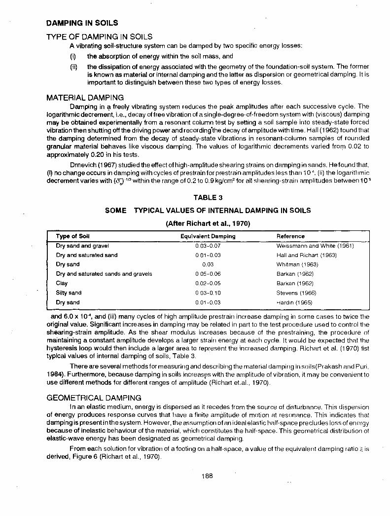
DAMPING IN SOILS
TYPE OF DAMPING IN SOILS A vibrating soil-structure system can be damped by two specific energy losses:
(i) the absorption of energy within the soil mass, and
(ii) the dissipation of energy associated with the geometry of the foundation-soil system. The former is known as material or internal damping and the latter as dispersion or geometrical damping. It is important to distinguish between these two types of energy losses.
MATERIAL DAMPING Damping in ~freely vibrating system reduces the peak amplitudes after each successive cycle. The
logarithmic decrement, i.e., decay of free vibration of a single-degree-of-freedom system with (viscous) damping rna~ be obtained experimentally from a resonant column test by setting a soil sample into steady-state forced vibration then shutting off the driving power and recording.the decay of amplitude with time. Hall ( 1962) found that the damping determined from the decay of steady-state vibrations in resonant-column samples of rounded granular material behaves like viscous damping. The values of logarithmic decrements varied from 0.02 to approximately 0.20 in his tests.
Drnevich (1967) studied the effect of high-amplitude shearing strains on damping in sands. He found that, (i) no change occurs in damping with cycles of prestrain for prestrain amplitudes less than 10-4
, (ii) the logarithmic decrement varies with (l'Q·1f.l within the range of 0.2 to 0.9 kg/cm2 for all shearing-strain amplitudes between 1 o-s
TABLE 3
SOME TYPICAL VALUES OF INTERNAL DAMPING IN SOILS
(After Richart et al., 1970)
Type of Soli
Dry sand and gravel
Dry and saturated sand
Dry sand
Dry and sattJrated sands and gravels
Clay
Silty sand
Dry sand
Equivalent Damping
0.03-0.07
0.01-0.03
0.03
0.05-006
0.02-0.05
0 03-0.10
0.01-0.03
Reference
Weissmann and White (1961)
Hall and Richart (1963)
Whitman (1963)
Barkan (1962)
Barkan (1962)
Stevens (1966)
Hardin (1 965)
and 6.0 x 1 o·4, and (iii) many cycles of high amplitude prestrain increase damping in some cases to twice the
original value. Significant increases in damping may be related in part to the test procedure used to control the shearing-strain amplitude. As the shear modulus increases because of the prestraining, the procedure of maintaining a constant amplitude develops a larger strain energy at each cycle. It would be expected that the hysteresis loop. would then include a larger area to represent the increased damping. Richart et al. (1970) list typical values of internal damping of soils, Table 3.
There are several methods for measuring and describing the material damping in soils(Prakash and Puri, 1984). Furthermore, because damping in soils increas~s with the amplitude of vibration, it may be convenient to use different methods for different ranges of amplitude (Richart et.al., 1970).
GEOMETRICAL DAMPING In an elastic medium, energy is dispersed as it recedes from the source of disturbance. This dispersion
of energy produces response curves that have a finite amplitude of motion at resonance. This indicates that damping is present in the system. However, the assumption of an ideal elastic half-space precludes loss of energy because of inelastic behaviour of the material, which constitutes the half-space. This geometrical distribution of elastic-wave energy has been designated as geometrical damping.
From each solution for vibration of a footing on a half-space, a value of the equivalent damping ratio~ is derived, Figure 6 (Richart et al., 1970).
188

Geometrical damping is present in geotechnical structures vibrating during earthquakes. No serious effort has been directed so far (1984) for determination of geometrical damping and Poisson's ratio in earthquake problems.
0.4 VERTICAL!; z
0.1
0.07
0.04
ROCKING!; 8
0.02
Bz, BX, s 8, ORB 1J'
FIGURE 6 Equivalent damping ratio for oscillation of rigid circular footing onthe clastic half-space (Richart et.al. 1970)
FUTURE TRENDS The determination of dynamic soil property is an expensive proposition everywhere. Therefore effort
need be directed in two ways:
(i) Collection of data bank and establishing correlations between static and dynamic properties. This may be possible in some soils like sands, and
(ii) Development of simpler and inexpensive techniques for in-situ determination of dynamic soil property for design of substructures.
Effort need be devoted to determine more realistic values of poisson's ratio and its variation with strain. Also realistic values of both material and more importantly geometrical damping need be determined. The progress in understanding the behaviour of dynamic soil property and its determination in the last two decades has been phenomenal. But we still have to go a long way in introducing desired economy in this effort.
DISPLACEMENT OF RIGID RETAINING WALLS DURING EARTHQUAKES
Retaining structures have suffered extensive damage during strong earthquakes. Such damages during past earthquakes have been documented by Duke and Leeds (1963) for 1960 Chilean earthquake, by Ross et al. (1969) for 1964 Alaska earthquake and by Clough and Fragaszy (1977) for 1971 San Fernando earthquake. Several cases of damage to retaining structures during the recent earthquakes in Greece and Italy will be presented during the 9th World Conference on Earthquake Engineering 1984, San Francisco, CA.
The question of displacements of retaining walls has engaged the attention of several investigators. It would be ideal to establish relationship between strain in the soil sample in triaxial test and strain (or deformation) in the structure in the field. This type of solutions have been developed by Makdisi and Seed (1978) for deformations in earth dams and Saran et. al. (1977) and Prakash et.al. (1984) for settlements of footing. No such solutions have been developed for retaining walls.
Estimation of displacements of retaining walls during and after an earthquake are important from safety
189
of such structures. Design methods of rigid retaining walls are being developed based upon permissible displacements.
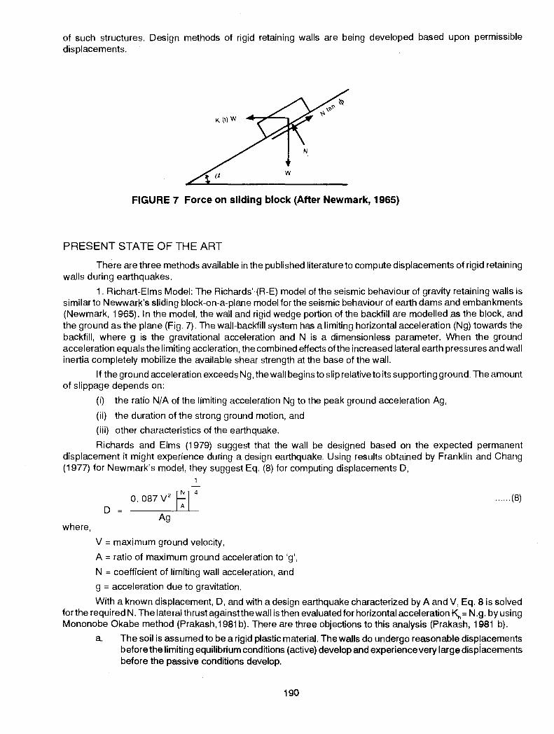
FIGURE 7 Force on sliding block (After Newmark, 1965)
PRESENT STATE OF THE ART
There are three methods available in the published literature to compute displacements of rigid retaining walls during earthquakes.
1. Richart-Eims Model: The Richards' (R-E) model of the seismic behaviour of gravity retaining walls is similar to Newwark's sliding block-on~a-plane model for the seismic behaviour of earth dams and embankments (Newmark, 1965). In the model, the wall and rigid wedge portion of the backfill are modelled as the block, and the ground as the plane (Fig. 7). The wall-backfill system has a limiting horizontal acceleration (Ng) towards the backfill, where g is the gravitational acceleration and N is a dimensionless parameter. When the ground acceleration equals the limiting accleration, the combined effects ofthe increased lateral earth pressures and wall inertia completely mobilize the available shear strength at the base of the wall.
If the ground acceleration exceeds Ng, the wall begins to slip relative to its supporting ground. The amount of slippage depends on:
(i) the ratioN/A of the limiting acceleration Ng to the peak ground acceleration Ag,
(ii) the duration of the strong ground motion, and
(iii) other characteristics of the earthquake.
Richards and Elms (1979) suggest that the wall be designed based on the expected permanent displacement it might experience during a design earthquake. Using results obtained by Franklin and Chang (1977) for Newmark's model, they suggest Eq. (8) for computing displacements D,
where,
D 0. 087 V
2 t;] 4
Ag
V =maximum ground velocity,
A= ratio of maximum ground acceleration to 'g',
N =coefficient of limiting wall acceleration, and
g = acceleration due to gravitation.
...... (8)
With a known displacement, D, and with a design earthquake characterized by A and V, Eq. 8 is solved for the required N. The lateral thrust againstthe wall is then evaluated for horizontal acceleration~= N .g. by using Mononobe Okabe method (Prakash, 1981 b). There are three objections to this analysis (Prakash, 1981 b).
a. The soil is assumed to be a rigid plastic material. The walls do undergo reasonable displacements before the limiting equilibrium conditions (active) develop and experience very large dispiacements before the passive conditions develop.
190

b. The physical properties of the system and its geometry (particularly its natural period) are not considered.
c. Walls may undergo displacements by either sliding or tilting or both. This method does not consider this difference in the physical behaviour.
2. Solutions in Pure Translation: In this analysis, it is assumed that (Nandkumaran, 1973)
a. The wall undergoes displacement in translation only.
b. The force-displacement relationships behind the wall and at the base are selected based on observed behaviour· of walls.
A model was thus set up and displacements have been computed for walls with natural periods ranging from 0.2 to 1.0 sec and a large number of other variables affecting the displacement, e.g., ground acceleration, period of ground motion, and damping in the system. The method has been briefly described elsewhere by (Prakash et. al., 1981 a). Although realistic soil behaviour has been considered in this analysis, the walls undergo rotation in addition to translation.
3. Solutions in Pure Rotation: A model for computation of rotational displacement of rigid walls independent of sliding displacements has been developed by Prakash et. al., (1981 b). The analysis is based on the following assumptions:
a. Rocking vibrations uf the wall about its heel is independent of sliding vibrations.
b. The earthquake motion may be considered as an equivalent sinusoidal motion having constant peak accelerations.
c. Soil participating in vibrations may be neglected.
d. The soil stiffness towards and away from the fill have been determined in a manner as in translation analysis.
It was found that the contribution of rotational displacement is significant in typical walls.
DISCUSSION
All the above three methods for computing displacements of retaining wall are incomplete in one respect or the other. A model with realistic dynamic soil property needs be developed fully.
Another question which needs critical study is the amount of "permissible displacements" of rigid retaining walls. Not enough information is available from case histories on displacements of retaining walls caused by earthpressure and interaction effects alone (excluding liquefaction failure behind and at the base of the walls).
Prakash (1981 b) has advocated full scale tests on retaining walls for monitoring the displacements. A first proposal of this kind has been prepared by Prakash et.al. (1984). It is believed that more information will be available on these questions at the Earthquake Conference in San Francisco in July 1984.
Mt
m4
f m.-•
mn
FIGURE 8 Pile-structure Idealization (After, Chandra Sekharan).
191

0.8
0.6
0.4
0.2
0
PILE FOUNDATION UNDER EARTHQUAKES
Generally, there are three techniques that can be used to solve problems of soil-pile superstructure interaction under dynamic loads (Novak, 1977a). The first represents soil as a continuum with linear elastic properties. It correctly represents geometric damping as well as soil layer response (Novak and Nogami, 1977; Novak, 1977a)\l.n the second, the finite element technique is used to represent the pile and the soil. This method offers a maximum flexibility for the variation of soil-pile properties (Novak, 1977a and Kuhlemeyer, 1979). The third representslhe soil-pile system by a set of discrete lumped masses, springs and dashpots. This approach can be used to incorporate the depth and non-linear variations of the soil properties in more detail. These variations depend upon the definition of the local soil stiffness and geometric damping (Penzien et. al., 1964 Penzien, 1970; Prakash and Chandrasekaran, 1973, 1977).
A reasonably practical solution for soil-pile interaction under dynamic loads has been proposed by (Chandrasekaran 1974, Prakash and Chandrasekaran 1980 and Prakash, 1981 a).
Pile-structure idealization in this approach is shown in Fig. 8. For evaluating the free vibration characteristics, the modal analysis is performed by using successive approximations of the natural frequencies of the system with an initially assumed value and related end conditions.
Information has been obtained for piles embedded in soils in which the soil modulus can be considered either to remain constant or to vary linearly with depth. In both of these cases, solutions have been obtained for natural frequency; modal displacements, slopes, bending moments, shear forces, and soil reactions along the lengths of the piles in the first three modes of vibrations (Chandrasekaran, 1974). Non-dimensional frequency plots are drawn as shown in Fig. 9. Based upon these solutions, a method of aseismic design of piles has been proposed by Prakash (1981 a).
......
~ /) v
(b)
-._
--
1.3
~ 1.1 ...J 0
u. ~
0 0.9 0 ~ >-g 0.7 ., :::J 0" ., u: 0.5
0
_u-~ -
I "\._ PILE TOP FIXED AGAINST ROTATION
I J.. I 1'\
?' \.,.. PILE TOP FREE TO ROTATE
I u
SOIL-MODULUS CONSTANT WITH DEPTH {a) FIRSTMODE OF VIBRATION
2.0 4.0 6.0 8.0 10.0 12.0 14.0 16.0
(a) Maximum depth factor z max
. r T=0.75, 1.0,1.5 m 1.3 PILE TOP FIXED AGAINST ROTATION
~
t_ T= 2.0m ..,
.'L. T =3.0 m 0
...J CIJ
LL. 1.1 t; 0 til
FIRST MODE OF VIBRATION
v- T=0.75, 1.0,1.5m I :::
PILE TOP FREE TO ROTATE (~
~ >' T 2.0 m :. 0.9 FREE MODE OF VIBRATION
f SLI Wn1 J w 1 - --I I gnh t'
(J
c: ., :::J
~ 0.7 LL. c:v
... v 11
-T=3.0m
(C) Fsl1 = wn! ../.!!....
---._
1 -2.0 4.0 6.0 8.0 10.0 12.0 14.0 16.0 0.5 ~ I 1 gnh • t2
0 2.0 4.0 6.0 6.0 10.0 12.0 14.0 16.0
(b) Maximum depth factor Zmax (c) Maximum depth factor Zmax
FIGURE 9 Non dimensional frequency factors in first mode of vibrations (a) Soil modulus constants with depth, (b) soil modulus linaerly varying with landdepth and pile top free (c) soil modulus linearly varying with depth and pile top restrained against rotation. (AfterPrakash and Chandra Sekharan, 1977)
192

Novak (1977 b) proposed a model for solution of vertical vibrations of single piles. In this solution pile stiffness and damping is determined from elastic constants of the pile and soil. For pile groups Novak and Grigg (1976) suggested :hat the deflection factors proposed by Poulos (1968) for groups of statically loaded piles may be applied to pile groups undergoing steady state vibrations. Also Novak and Beredugo (1 S72) have proposed methods to compute stiffness and geometrical damping for embedded footings. These solutions can be applied to pile cap directly. These are added to stiffness and damping values of pile group.
Novak ( 197 4) derived equations 9 to 14 for lateral stiffness and damping constants for single pile also considering (i) translation alone (ii) rotation alone and, (iii) coupled rotation and translation:
where
1 Translation stiffness constant, k
XX
EP IP (f ) r 3 'x1 0
EP IP Translation damping constant, c = -r 2
" (fx 2 ) XX 0 s
Rotation stiffness constant, k~
Rotation damping constant, c~
Cross - stiffness constant, k~+
Cross - damping constant, c~+
E I ~(f)
r +J 0
E I ~(f) v +2
s
I = moment of inertia of pile cross-section, p
E = Young's modulus of pile, p
v. = shear wave velocity in soil,
Vc = longitudinal wave velocity in pile,
ro =pile diameter, and
f = constants.
.. (9)
.. (1 0)
... (11)
... (12)
.. (13)
... (14)
Effect of group action on stiffness and damping has also been obtained. Solutions of piles under torsion have been obtained by Novak and Howell (1977). A design procedure for pile supported machine foundations has been proposed by Prakash and Puri (1984).
DISCUSSION
The main question in pile analysis under earthquake is "What are the amounts of vertical settlement and lateral deflections under earthquake-type loading?" The question of settlement under vertical vibrations has been studied to a degree by Swiger (1948), Barkan (1957), and Prakash and Agarwal (1971). The results of detailed study by Ghumman (1984) have not yet become available. There is a need to study the question of simultaneous vertical and lateral vibrations of piles, both analytically and experimentally.
The question of lateral deflections under earthquake-type vibrations can be answered by the solutions presented by Prakash (1981 a). These solutions are based upon the extension of the concept of modulus of subgrade reaction. Therefore, all the shortcomings of this concept are obviously inherent in this analysis (Terzaghi, 1955; Matlock et. al., 1978). Another limitation of this method is that the mass of the super-structure is assumed to be concentrated at the top of the pile.
How much is this concentrated mass? Is it the mass of the total load on each pile or a fraction of it? Because the load on the pile is not really concentrated load but is transferred from several storey heights, the
193
interaction effects of the superstructure are not considered. Very little information is presently (1983) available on the subject.
The analysis of group is at i:lest elementary till to-date (1983). In one study, the increase of piles to 64 in number led only to 2.5 times increase in stiffness. (Prakash, et.al., 1983). Therefore, the analysis needs further refinements.
LIQUEFACTION OF SOILS
In saturated soils, large pore pressures may build up during earthquakes. The transfer of effective stress from the soil grains takes place into pore water. This reduces the strength of soils. The state when the effective stress becomes zero is initial liquefaction.
Several criteria have been proposed as an index of liquefaction e.g., critical void ratio (Casagrande, 193e), critical acc~leration (Maslov, 1957), Japanese rule of thumb and Russian field criteria based on blasting tests and Standard Penetration tests (Prakash, 1981 a)
There are a few important questions that need be examined to solve the problem of liquefaction of sands.
1. In dense sands(with void ratio smaller than critical void ratio) negative pore pressures are developed in undrained shear. Seed and Lundgren (1954) had found that in rapid trans1ent test with rate of deformation of about 1 00 em/sec (corresponding to loading time of about 0.02 sec) the strength of dense sands was about 15 per cent higher than that in static undrained tests. Pore pressures were not measured in these tests. But it is reasonable to assume that the negative pore pressures in the two tests were not the same, resulting in pore pressure gradients in rapid transient tests. However, in dense sands under cyclic triaxial tests, Seed and Lee (1960) have observed the development of positive pore water pressures, till initial liquefaction occurs. No rational explanation is available on the change in nature of behaviour of sand from the static and rapid transient tests to cyclic triaxial tests. Tests on reconstituted samples in triaxial and oscillatory simple shear show similar trends although the numerical results are not identical (Prakash, 1981 a). However in vibration table studies, Gupta (1979) did observe negative pore pressures on the four sands tested by him, with initial relative density of 70 per cent and more and acceleration level of 40 percent g. Below this level of excitation there was no change in the pore pressure value. This is the only data in which negative pore pressures have been observed in a cyclic test. Casagrande (1975) suggests that behaviour of dense sand in the triaxial and in the field may not be the same and this difference in behaviour if any can be inferred from carefully obtained field data only.
2. It is recognized that the fabric or structure of the aggregation of soil particles at a given relative density, the age of the samples at the time of testing, the degree of overconsolidation, and the application of repeated extremely small shearing stresses between the time the samples were formed and tested affect the susceptibility of sands to liquefaction. Relevant studies indicate thataging, over-consolidation, and microvibrations all tend to increase the resistance to liquefaction of reconstituted laboratory samples even at identical relative densities. Moreover, this increase can readily be destroyed by disturbance.
These.various findings justify the speculation tnat the same factors that tend to increase the resistance to liquefaction in the laboratory are likely to be active under field conditions (Peck, 1979). This speculation leads to two tentative conclusions : (a) Unless the cyclic loading tests used to evaluate liquefaction pote:-~tial can be performed on absolutely undisturbed samples, which is'manifastly impossible, the results will probably indicate too great a likelihood of liquefaction; and (b) in many instances the resistance to liquefaction in the field may be appreciably, even spectacularly greater than that detemlined on the basis of conventional cyclic laboratory tests on reconstituted or even "undisturbed" samples if no allowances are made for the various possible beneficial effects such as time, repeated small shearing forces, and stress history.
"Hence no evidence can be considered reasonably adequate until there is sufficient field experience to determine whether the phenomena observed in the laboratory are indeed the same as those that operate in the field. It must also be determined whether predictions based on laboratory studies and theories are indeed fulfilled in the field. With respect to liquefaction during earthquakes, we have very meagre field evidence. There are as yet no case histories that include both thorough laboratory testing under cyclic conditions of the materials in their undisturbed state before the earthquake and good records of the earthquake motions at places where liquefaction has been observed".
The above discussion of Peck (1979) highlights the importance of field evidence of liquefaction to be collected during earthquakes.
3. Efforts have been directed to relate the occurrence or absence of liquefaction with standard penetration
194

tests. Seed (1979) has proposed plots of (a) cyclic stress ratio causing peak cyclic pore pressure ratio of 100 per cent with limited shear strain potential and (b) corrected N values, for effective vertical stress of 1 t/ft2 and for earthquakes of magnitudes 6, 7-1/2 and 8-1/4. These plots are based partly on field evidence and partly on large scale vibratory tests on reconstituted samples. Seed and ldriss (1983) have analysed a large number of field liquefaction data and recommend the use of Figure 1 0 for predicting liquefaction from Standard Penetration values.
0.5
0.4
-> ~ 0.3 > qs
1-' 0
~ ., ., ~ ., .!::! u 0.2 >-()
0.1
~I I I I I ":'I I ,. I I ., . I .. 1 "I o "' ~I ~I ?1
tv I ::I ~I
I
10 20
':i! ,'f'l I I ~I I I I
~, ~I
I 1 I I I I
I I I I .I
I
Corves applicable for
conditions where a.<1
ton persq ft.
30
Modified penetration resistance, N, blows/tt
40
FIGURE 10 Chart for evaluation of liquefaction potential tor sands for different magnitude earthquakes (Seed and idriss 1983)
DISCUSSION
There are basically two methods for estimating liquefaction of horizontal ground :
( 1) Estimate cyclic stress at a depth by response analysis or simplified analysis and compare with cyclic stress causing liquefaction from cyclic laboratory test data (Seed and ldriss, 1971).
(2) Estimate cyclic stress at a depth and compare with stress causing liquefaction from Fig. 1 0 (Seed and ldriss, 1983).
Certainly the second method has advantage in being based on field evidence of liquefaction.
It will be seen that there is a growing trend to simplify the analysis of a complicated phenomenon like liquefaction. This is a welcome trend. However, the big question is
195

"How much standard is a STANDARD PENETRATION TEST?" (Schemertman 1975, 1977).
Role of Centrifuge Model Testing
The aim of the model testing in Geotechnical Engineering is one or more of the following :
(i) to study the failure mechanism,
(ii) to study the influence of various parametP.rs governing the behaviour,
(iii) to verify the predictions of analytical and numerical solution, and
(iv) to predict the prototype behaviour.
If the results of model tests are to serve any of the objectives stated above, complete similarity between model and prototype should be established. In conventional model tests, it is not feasible to impose complete similarity. For example the stability of a saturated clay slope and a cut is represented by the non-dimensional
stability number, ~ When an embankment is modelled in a ratio of 1 : N made of the same soil as yH
that of prototype, the ~tability number of the model slope does not remain the same as of the prototype but is
increased by N-times i.e.. CN Therefore, if failure is just to occur in the prototype, it will not occur in model. yHP
This is due to the fact that the forces due to the self weight of the soil which constitute the actuating forces are not simulated in the model whereas the strength remains the same as that in the prototype.
Centrifuge model testing provides a means to simulate self weight stresses and thus produces results which are more realistic and very close to the behaviour of prototype.
SCALE FACTORS AND. SIMILARITY In static problems, reduction of length by model factor liN meant area and mass reductions, and increase
of acceleration by a model factor N would give identical stresses at homolog us points in model and prototype :
Scale factors
length 1IN
area 1IN 2
mass 1IN 3
acceleration N
stress
time 1IN 2
In dynarrftc problems similarity requires
Length 1 IN energy 1 IN 3
Velocity 1
acceleration N
time 1IN
frequency N
force
stress
strain
density
1IN 2
1
1
It may be noted that similarity requirement of time in static and dynamic problems are different. It is due
to the fact that the time in static problems is related to the drainage path ( Cv · t \ Therefore time becomes ~ H2 )
proportional to the square of the length of drainage path which in turn has a scale factor of 1IN2 In dynamic problem the time is related to the amount of movement in a certain period and therefore related directly to the amount ·at movement and thus has a scale factor of 1IN.
The above listing of similarity requirement shows that scaling length, acceleration, time, frequency, force and energy as shown above will make the observations of velocity, stress, strain and density in the model same as of prototype.
,;.;_
196

DESCRIPTION OF CENTRIFUGE SET-UP
The centrifuge set-up consists of a rotating arm driven by an electric motor. The model is prepared in a basket and attached to one end of the rotating arm. A dummy basket is attached to the other end of the rotating arm to counter balance the weight of the model basket. The model can be loaded when the model basket is in flight using appropriate technique. The behaviour of the model cfuring the run can be monitored by using closed circuit TV, displacement transducers such as LVDT, strain gauges, and piezometers.
If R is the radius of the centrifuge (i.e. equal to its arm length) then when it rotates at a speed V, the soil model is subjected to a radial acceleration 'a' given by
where
v2 a = - = (2llf1)2 R = Ng
R n = revolutions per sec
N = (2llf1)2R I g
As the soil model is held at a fixed radius R, a unit value of soil mass exerts as inertia force equal to N times the unit weight of soil i.e. N y, In this way self weight stresses are simulated in centrifuge model.
DEVELOPMENTS IN CENTRIFUGE MODEL TESTING
The centrifuge model testing was pioneered in USSR. At present, the Geotechnical certrifuge testing facility is available in many other countries such as UK, Japan, USA, France and Denmark. A variety of Geotechnical Engineering problems such as stability of slopes, excavations and tunnel roofs, behaviour of offshore gravity platforms dynamically loaded foundations and liquefaction of soils have been successfully tackled at the various centrifuge centres. The Geotechnical Engineering Group at the University of Cambridge is particularly very active. The twentieth Rankine's Lecture delivered by Schofield (1980) provides state-of-theart on the development in Centrifuge Model testing. Work is in progress at a number of centres on the development of dynamic and earthquake modelling capabilities, some of which are reported in the 'International Conference on Recent Advances in Geotechnical Earthquake Engineering and Soil Dynamics' held at University of Missouri, Rolla, USA in 1981 . It is expected that a variety of dynamic and earthquake model tests will be conducted at the Geotechnical Centrifuge Centres and these tests will provide abundant data to design prototype works.
RELEVANCE IN INDIAN CONTEXT
The problems associated with the design and construction of earth structures such as earth and rockfill dams, tunnels and excavations in earthquake prone areas are the most challenging and important problems facing the Geotechnical Engineers in our country. The design and construction of these structures are being carried out at the moment under a great number of uncertaintities resulting in conservative design, unpredictable safety, considerable delay in construction and high cost. These are due to lack of definite information on the behaviour of these structures, particularly under earthquake loadings. The centrifuge model testing provides ample opportunity to study the above problems and obtain enough insight on the behaviour of these structures to enable safe and economic design. The cost of centrifuge model tests can only be a very small fraction of the total cost of the projects and the savings it might affect due to economic design could as well meet the cost of a number of centrifuges. It is high time therefore that the Geotechnical Engineering Community makes effort to establish a large Centrifuge Model Testing facility in the country.
CONCLUSIONS
The important question of determination of dynamic soil properties, displacements of retaining walls during earthquakes, behaviour and design of pile foundations subjected to dynamic loads, liquefaction of soils and application of centrifuge model testing for earthquake loading have been discussed. The presentation of material is by no means complete, but it is hoped that useful discussions will be triggered by this presentation. These discussions may pave the way for future directions of work for the geo-technical community in our country.
197

ACKNOWLEDGEMENTS
The author is grateful to Dr. V.H. Joshi and Dr. Sw::Imi Saran for reading over the draft and their comments. Dr. G. Ramasamy assisted in preparing the write up on centrifuge model testing. Sri Amar Singh assisted in locating some useful material and proofing the text.
REFERENCES ANDERSON, D.G. and STOKOE, K.H. (1977) : "Shear Modulus : A time-Dependent Soil Property", Dynamic Geotechnical Testing, ASTM Spec. Tech. Pub. 654, Denver, Colo., JUNE, pp. 66-89.
BARKAN, D. D., (1957) : Foundation Engineering and Drilling by Vibration Method, Proc. IV ICSMFE 2 : 3-7.
BARKAN, D.O. (1962): "Dynamics of Bases and Foundations", McGraw Hill Book Co., New York, NY.
CASAGRANDE, A. (1936): "Characteristics ofCohesionless Soils Affecting the Stability of Earth Fills", J. 8os. Soc. Civil Eng., reprinted, Contributions to Soil Mech. 1925-1960, BSCE.
CASAGRANDE, A. (1975), "Liquefaction and Cyclic Deformation of Sands, A Critical Review", Fifth Pan American Cont. SMFE, 'Buenos Aires, Argentina, November.
CHANDRASEKARAN, V. (1974); "Analysis of Pile Foundations Under Static and Dynamic Loads," Ph.D. Thesis, University of Roorkee, Roorkee, India.
CLOUGH, G.W. and FRAGASZY, R.I. (1977): "A study of Earth loadings on Flooding Retaining structures in the 1971 San Fernando Vatley Earthquake", Proc. 6th World Cont. on Earthquake Engineering, New Delhi, India, pp. 2455-2460.
DRNEVICH, V.P. (1967): "Effect of Strain History on the Dynamic Properties of Sand", Ph.D. Dissertation, Univ. Michigan, 151 pp.
DUKE, C. M. and LEEDS, D.J. (1963): "Response of Soils, Foundations and Earth Structures to the Chilean Earthquake of 1960", Bull. Soc. Am 53 (2), pp. 309-350, February.
FRANKLIN, A. G. and CHANG, F.K. (1977): "Earthquake Resistance of Earth and Rock Fill Dams: ReportS: Permanent Displacement of Earth Embankments by Newmark's sliding Block Analysis", Misc. Paper 5-71-17, Soils and Pavement Lab. US Army Engineers Waterways Experiment Station, Vicksburg, Miss.
GHUMMAN, M.S. (1984): "Effect of Vertical Vibrations on the Penetration Resistance of Piles," Ph. D. Thesis, University of Roorkee, Roorkee (under preparation).
GUPTA, M.K. (1979): "Liquefaction of Sands During Earthquakes", Ph.D. Thesis, University of Roorkee, Roorkee, India.
HALL, J.R. Jr., (1962): "Effect of amplitude on Damping and Wave Propagation in Granular Materials", Ph.D. Dissertation, University of Florida, August, pp. 172.
HARDIN, B. 0. (1978): "The Nature of Stress-Strain Behaviour of Soils," State-of-the Art Report, Proc. ASCE Speciality Cont. on Earthquake Engineering and Soil Dynamics, Pasadena, pp. 3:90, June.
HARDIN, 8.0. and W.L. BLACK, (1969): "Closure to Vibration Modulus of Normally Consolidated Clays", J.SMFD, ASCE, 95 : SM6 : 1531-1532.
ISHIHARA, K., (1971): "Factors Affecting Dynamic Properties of Soils", Proc. 4th Asian Reg. Cont. on Soil Mechanics and Foundation Engineering, Bangkok, 2:87-110.
KUHLEMEYER, R.L., (1979) "Static and Dynamic Laterally Loaded Piles", J. Geot. Eng. Divn, ASCE, 105:GT2289-304.
LODDE, P.J., (1977): "Shear Moduli and Material Damping Ratios of San Francisco Bay Mud", Master's Thesis, Unive. Texas, Augstin, Tex.
MAKDISI, F.l. and SEED, H.B., (1978): "Simplified Procedure for Estimating Dam and Embankment Earthquake induced deformations", J. Geot. Eng. Div. ASCE 104:GT7:849-967.
MASLOV, N.N., (1957): "Questions of Seismic Stability of Submerged Sandy Foundations and Structures", Proc IV ICSMFE: 1. 368-372.
MATOCK, H., STEPHEN, C. F. and BRYANT, L.M. (1978): "Simulation of Lateral Pile Behaviour under Earthquake Motion", Proc. ASCE Speciality Conference on Soil Dynamics and Earthquake Engineering Pasadena, 2: JUNE: 600-619.
NANDKUMARAN, P., (1973): "Behaviour of Retaining Walls under Dynamic Loads", Ph.D. Thesis, Roorkee University, Roorkee, India.
NEWMARK, N.M. (1965) : "Effect of Earthquake on Dams and Embankments", Geotechnique, 15:2; 139-160.
NOVAK, M., (1974): "Dynamic Stiffness and Damping of Piles", Can. Geot J. 11 : 4: 574-598.
NOVAK, M., (1977a): "Foundations and Soil Structure Interaction," Theme Report, Topic 4, Proc. VI World Conference on Earthquake Engineering, New Delhi: 2: 1421-1448.
198

NOVAK, M., (1977b), "Vertical Vibration of Floating Piles", J. Eng. Mechs Divn. ASCE: 103: EMI: 153-168.
NOVAK, M., and BEREDUGO, Y.O., (1972): Ve~ical Vibration of Embedded Footings, JSMFD, ASCE, 98:12.
NOVAK, M., GRIGG, R.F. (1976): "Dynamic Experiments,.with Small Pile Foundation," Can. Geot, J., 13:4:372-395.
NOVAK, M., and HOWELL, J.F. (1977): "Torsional Vibrations of Pile Foundations, J. Geot. Eng. Divn, ASCE, 103: G14:271-285.
NOVAK, M., and NOGAMI, T. (1977): "Soil-Pile Interaction in Horizontal Vibration, Int. J. Earthquake Eng. Structural Dynamics : 5:263-281.
PECK, R.B:, (1979): "Liquefaction Potential-Science versus Practice", J. Geotech Eng. Divn., ASCE, 105:GT3:393-398.
PENZIEN, J., (1970): "Soil-Pile Foundation Interaction" in R.L. Wiegel (ed), Earthquake Engineering, Prentice-Hall, Inc., Englewood Cliffs, NJ.
POULOS, H. G., (1968): "Analysis of the Settlement of the Pile Groups", Geotechnique. 18:4.
PRAKASH, S., (1981a): "Soil Dynamics", McGraw-Hill Book Co., New York, NY.
PRAKASH, S., (1981 b): "Analysis of Rigid Retaining Walls During Earthquakes: State-of-the-Art," Pro c. Intern. Cont. of Recent Advances in Geotech. Earthquake Eng. and Soil Dynamics, 3, p. 993-1020, St. Louis, M 0, April.
PRAKASH, S., (1981 c): "Geotechnical Earthquake Problems ofthe Future", International Convention of ASCE, Pre print No. 81-0~7. Mass New York.
PRAKASH, S. and AGARWAL, H. P. (1971): "Effect of Vibrations on Skin Friction of Piles", Proc. Fourth Asian Regional Cont. Soil Engg., Bangkok, Vol. 1, July: 203-208.
PRAKASH, S. and CHANDRASEKARAN, V. (1973): "Pile Foundations Under Lateral Dynamic Loads," Proc. VIII: ICSMFE Moscow, 2:190-203.
PRAKASH, S. and CHANDRASEKARAN, V. (1977): "Free Vaibration Characteristics of Piles", Proc. IX ICSMFE Tokyo, 2:333.
PRAKASH, S. and CHANDRASEKARAN, V. (1980): "Analysis of Piles in Clay Against Earthquakes", Pre-print No. 80-1 09, ASCE Convention and Exposition, Portland, Ore, April.
PRAKASH, S., JOSHI V.H. and SARAN, S. (1984): "Displacements of Rigid Retaining Walls", Paper Submitted for 8th World Conference on Earthquake Engineering.
PRAKASH;S. and PURl, V. K. (1981a): "Observed and Predicted Response of a Machine Foundation," Proc. XI CSMFE Stockholm, June. 3:269-272
PRAKASH, S. and PURl, V.K. (1981b): "Dynamic Properties of Soil from In-Situ Tests," J .. Geot. Eng. Divn. ASCE: GT7: 943-63.
PRAKSH, S. and PURl, V.K. (1981c) : "On Design of Machine Foundations, panel Report to session X on Soil Dynamics,", X ICSMFE Stockholm.
PRAKASH, S. and PURl, V.K. (1988): "Analysis and Design of Machine Foundations", Published by John Wiley, New York, NY.
PRAKASH, S., PURl, V.K. and KHA '!<ER, J. (1981): "Displacement of Rigid Walls in Rocking," Proc. Intern. Cont. Recent Advances in Geotech. Earthqua~<e Engineering and Soil Dynamics, 3 : 1021-1025, St. Louis, Mo, April.
PRAKSH, S., GO PAL RANJAN and KRISHAN KUMAR, (1983) : "Dynamic Analysis & Design for a ?t Forging Hammer at Derabassi Civil Engineering Studies-Report No. University of Roorkee October GEP-GR-176(83).
PRAKASH, S., SARAN S. and SARAN, U.N. (1984): "Settlements of Footings Based on Constitutive Laws", Paper submitted to ASCE for publication in Geotechnical Engineering Division.
AI CHARDS, R. JR. and ELMS, D.G. (1979): "Seismic Behaviour of Gravity Retaining Walls, J. Geot. Eng. Divn., ASCE: 105: GT4: 449.
RICHART, F. E., JR., (1977): "Dynamic Stress-Strain Relations for Soils-State-of-the-Art Report," Proc. Ninth Inter. Cont. Soil Mech and Found. Eng., Tokyo, 2: 605-612.
RICHART, F. E., JR., HALL, J.R. and WOODS, A.D. (1970): Vibrations of Soils and Foundat"1on", Prentice-Hall, Inc., Englewood Cliffs, N.J.
ROSS, G.A., SEED, H.E. and MIGLIACCIO, R. (1969): "Bridge Foundation Behaviour in Alaska Earthquake", JSMFD ASCE, 95: SM4: 1007-1038.
SARAN, S., PRAKASH, S. and SARAN, U. (1977), "Pressure Settlement Characteristics from Constitutive Laws", Proc. Intern. Symposium on Soil Structure Interaction, Roorkee, 259-264.
SCHMERTMANN, J.H., {1975): "Measurement of In Situ Shear Strength", Proc. ASCE Speciality Conference on In-situ Measurement of Soil Properties, Raleigh, N.C., 2, pp. 56-138.
199

SCHMERTMANN, J.H. (1977): "Use the SPT to Measure Dynamic Soil Properties? Yes, But. .. " Dynamic Geotech. Testing, ASTM, Spec. Tech. Pub. 654, pp. 341-355, June.
SCHOFIELD, A.N. (1980}: "Cambridge Geotechnical Centrifuge Operations", Geotechnique 30:3:227-268.
SEED, H. B., (1979): "Soil Liquefaction and Cyclic Mobility Evaluation for Level Ground During Earthquakes," J. Geot, Eng. Div., ASCE, 105: GT2: 201-255.
SEED, H. B. and IDRISS, I.M. (1970}: "Soil Module and damping Factor for Dynamic Response Analysis", EERC 70-10 Earthquake Engineering Research Centre, Berkeley, Calif.
SEED , H.B. and IDRISS, I.M. (1983} : "Ground Motions and Soil Liquefactions During Earthquakes". Earthquake Engineering Research Institute
SEED, H.B. and LEE, K.L. (1960}: "Liquefaction of Saturated Sands During Cyclic Loading," JSMFD, ASCE; 92:SM6:1 05-134.
SEED, H.B. and LUNDGREN, R. (1954}: "Investigation of the Effect of Transient Loading on the Strength and Deformation Characteristics of Saturated Sands," Proc., ASTM:54:1288-1306.
STEVENS, H.W. (1966}: "Measurement of the Complex Moduli and Damping of Soils Under Dynamic Loads", U.S. Army Cold Regions Research & Engg. Laboratory, Hanover. N.H., Tech. Pub. no. 173.
SWIGER, W.F. (1948): "Effect of Vibration on Piles in Loose Sand", Proc. II, ICSMFE Rotterdam:2: 19.
TERZAGHI, K., (1955): "Evaluation of Coefficients of Subgrade Reaction," Geotechnique: 5: 297-325.
WEISSMAN, G.F. and WHITE, S.R. (1961}: "DampingCapacityofSome Granular Soils", Symposium on Soil Dynamics ASTM, Special Tech. Pub. no. 305, pp 45-59.
WHITMAN, R.V., (1963}: "Stress-Strain Time Behaviour of Soil in One-Dimensional Compression", Rep. R. 63-25, Dept. of Civil Engr., Massachusetts Institute of Technology.
WOODS, R. D., (1978): "Measurement of Dynamic Soil Properties", State-of-thecArt Report, Proc. ASCE Speciality Conf. on Earthquake Engineering and Soil Dynamics, Pasadena, pp. 91-178, June.
200