Passivhaus Valplas Offices Project Documentation - ID … · Hollowcore plank and compression layer...
26
1 Passivhaus Valplas Offices Project Documentation - ID 4598 Office building for Antolin Group – Valplas, in Sollana, Valencia. Spain. Project Designer Bruno Gutiérrez Cuevas, arq. Emmepolis Novecento www.emmepolis900.com First Passivhaus office building certified in Spain, with an area of 1,436 m2 and three floors. The bioclimatic design was vital to get the values obtained in the PHPP. Due to the north orientation and the volume imposed by the conditions of the plot and the functional program, We have mainly worked on optimizing hollows, trying to find a balance between the contributions of natural light and reducing transmission losses. The location, attached to the south of the existing warehouse facade, cuts off the night cooling created by the natural cross ventilation. To reduce this demand, we have projected two interior courtyards that also intensify the contribution of natural light. See also http://www.passivhausprojekte.de/index.php#d_4598 Project ID: 4598 Special features: Standard Passivhaus adapted to Mediterranean Climate. U-value of exterior wall 0,275 W/(m²K) PHPP Annual Heating Demand 13,37 kWh/(m²a) U-value basement ceiling 0,640 W/(m²K) U-value of the roof 0,207 W/(m²K) PHPP Primary Engine demand 116 kWh/(m²a) U-value window 1,35 W/(m²K) Heat recovery efficiency 87,0 % Pressure test n50 0,33 h -1
Transcript of Passivhaus Valplas Offices Project Documentation - ID … · Hollowcore plank and compression layer...
1
Passivhaus Valplas Offices
Project Documentation - ID 4598
Office building for Antolin Group – Valplas, in Sollana, Valencia. Spain.
Project Designer Bruno Gutiérrez Cuevas, arq.
Emmepolis Novecento
www.emmepolis900.com
First Passivhaus office building certified in Spain, with an area of 1,436 m2 and three floors. The bioclimatic design was vital to get the values obtained in the PHPP. Due to the north orientation and the volume imposed by the conditions of the plot and the functional program, We have mainly worked on optimizing hollows, trying to find a balance between the contributions of natural light and reducing transmission losses. The location, attached to the south of the existing warehouse facade, cuts off the night cooling created by the natural cross ventilation. To reduce this demand, we have projected two interior courtyards that also intensify the contribution of natural light.
See also http://www.passivhausprojekte.de/index.php#d_4598 Project ID: 4598
Special features: Standard Passivhaus adapted to Mediterranean Climate.
U-value of exterior wall 0,275 W/(m²K) PHPP Annual
Heating Demand 13,37
kWh/(m²a) U-value basement ceiling 0,640 W/(m²K)
U-value of the roof 0,207 W/(m²K) PHPP Primary
Engine demand
116 kWh/(m²a)
U-value window 1,35 W/(m²K)
Heat recovery efficiency 87,0 % Pressure test n50 0,33 h-1
2
1 Description of the construction task
Grupo Antolin Valplas
Some refurbishment work will be undertaken in the middle of the factory occupied by Grupo Antolín
Valplas, and a new office building will be built on the northern front of the plot. The activity of Grupo
Antolín Valplás is plastic injection.
The proposed new building consists of:
1. Construction of an office building replacing the current projection of the factory in the north with
three floors (main floor + 2).
- On the ground floor the building is divided into two areas. The first one is the Factory staff area,
where the changing rooms and toilets are located. As well as doctor's room and cures, a space for
living and dining hall with direct access to an outdoor resting area in the east wing. And the second
one is the Offices staff Area, which access is independent from factory staff. In this area the building
has the reception, a meeting room and the quality control laboratory.
- An open space office with some auxiliary rooms, archive room is located on the first floor, etc. On this
floor, the building also has the training room on the west side
- The second floor is very similar to the first one. There is an open space for office and several
auxiliary department associated with office use.
2. Construction of a facilities building of rectangular shape, located in the northwest corner with two
storeys high (main floor + 1).

3
2 Photographs of the elevation
North elevation of the Passivhaus building.

4
North elevation (parcial)
Patio

5
Patio

6
North elevation (parcial)
7
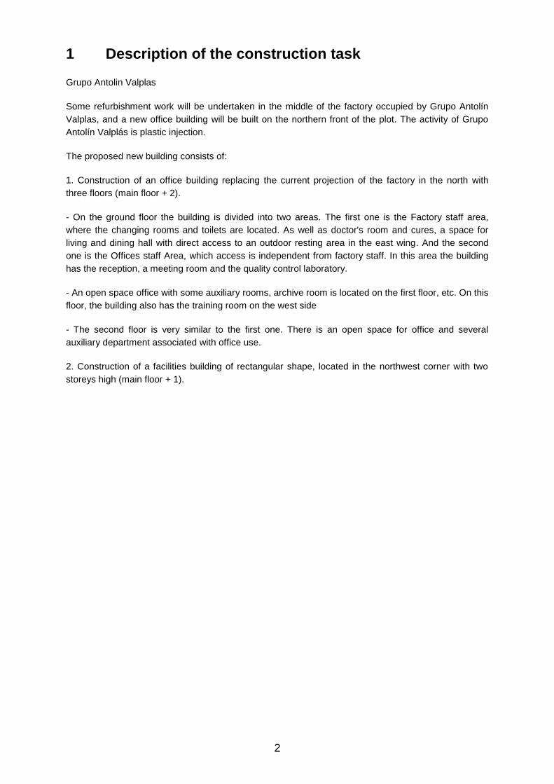
North and East elevation
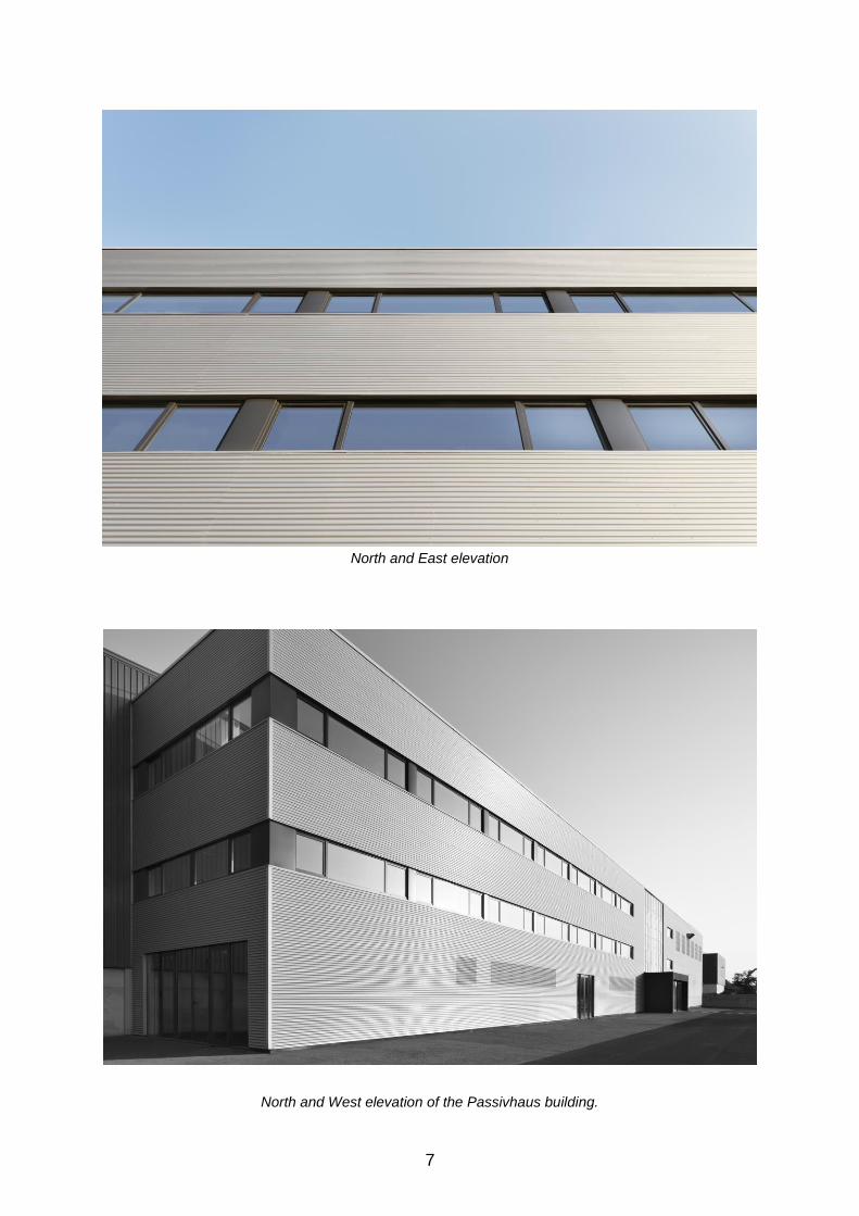
North and West elevation of the Passivhaus building.

8
North elevation (parcial)

9
3 Exemplary photograph of the interior
Office staff hall and reception
Open office space

10
Staircase and courtyard in second floor
Courtyard in first floor over the changing room

11
4 Cross – Section
In the north and east facades, isolation has been done with rigid mineral wool panel of 100 mm thick
with a thermal conductivity of 0.035 W / (mK). The entrance door canopy, the plinth and the courts
have been finished with SATE (External Thermic Isolation System), placing a double "Rockwool" high
density panel.
Isolation is continued in all facades and ensures the elimination of thermal bridges in the edges of the
slab and in the junctions with the roof. The exterior finish was made with cement mortar, reinforcing
fiberglass mesh, and three layers of flexible mineral stucco, waterproof, permeable to water vapour
and resistant to impact.
The heating network has been solved by two systems: one through the air ducts (hot / cold) and the
other a complementary Fan coils systems (hot / cold). The heat recovery unit is placed in the roof. It
has a battery placed at the outflow impulsion air ducts that is used to generate hot or cold air
according to demand.

12
5 Floor plans Passivhaus Valplas Office
Main Floor: Factory staff area with changing room and toilets, Doctor´s and cure room, Dining hall.
Office staff area with Reception, meeting room and Quality and Control Laboratory.
First Floor: open space office, auxiliary rooms, meeting rooms, archive room. Training room (on the
west side)
Second Floor: Open space for office and several auxiliary department associated with office use.

13
6 Construction including insulation of the floor slab
Elevator Core isolation
For avoiding thermal bridges in the basement ceiling structure, it is necessary to use extruded
polystyrene insulation pieces 100 mm thin, with a exterior waterproofing layer and draining sheet of
HDPE.
Wall and floor slab
From the outside to the inside: Drainig sheet of HDPE, Waterproof layer, extruded polystyrene Styrodur insolation 100 mm, Waterproof mortar plaster 15 mm, Honeycomb clay bricks 190 mm, gypsum plaster 15 mm.
U-Value
0,275
W/(m²K)

14
7 Construction including insulation of the exterior walls
The structure of the outer wall. The facade has been built by honeycomb clay block of 19 cm thick with a thermal conductivity of 0.28 W / (mK), it has been externally applied a layer of 15 mm waterproof mortar. In the north and east facades, isolation has been done with rigid mineral wool panel of 100 mm thick with a thermal conductivity of 0.035 W / (mK). The outside layer is an exterior corrugated steel sheet with an air chamber of 50 mm.
The entrance door canopy, the plinth and the opaque space between windows have been finished with SATE (External Thermic Isolation System), placing a double panel "Rockwool" high density of 110 mm thick with a thermal conductivity of 0.036 W / (mK). Isolation is continued in all facades and ensures the elimination of thermal bridges in the edges of the slab and in the junctions with the roof. The exterior finish was made with cement mortar, reinforcing fiberglass mesh, and three layers of flexible mineral stucco, waterproof to rainwater, water vapour permeable and resistant to impact.
Inside the closure it has been executed with plaster lining of 20mm thick, which ensures air tightness and water vapour permeability.
From the outside to the inside: Exterior Corrugated steel sheet, air chamber 50 mm, Rigid mineral wool insolation panel 100 mm, Waterproof mortar plaster 15 mm, honeycomb clay bricks 190 mm, gypsum plaster 15 mm.
U-Value
0,275 W/(m²K)
15
8 Construction including insulation of the roof
. .
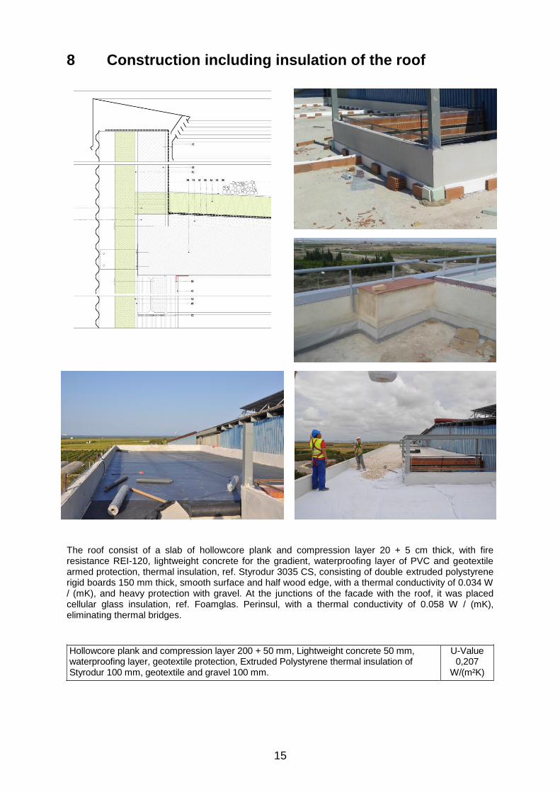
The roof consist of a slab of hollowcore plank and compression layer 20 + 5 cm thick, with fire resistance REI-120, lightweight concrete for the gradient, waterproofing layer of PVC and geotextile armed protection, thermal insulation, ref. Styrodur 3035 CS, consisting of double extruded polystyrene rigid boards 150 mm thick, smooth surface and half wood edge, with a thermal conductivity of 0.034 W / (mK), and heavy protection with gravel. At the junctions of the facade with the roof, it was placed cellular glass insulation, ref. Foamglas. Perinsul, with a thermal conductivity of 0.058 W / (mK), eliminating thermal bridges.
Hollowcore plank and compression layer 200 + 50 mm, Lightweight concrete 50 mm, waterproofing layer, geotextile protection, Extruded Polystyrene thermal insulation of Styrodur 100 mm, geotextile and gravel 100 mm.
U-Value 0,207
W/(m²K)

16
9 Cross-section of window including installation
drawing
It has been installed a high performance joinery, certified Passivhaus, ref. Alu Schüco Inside-82, with a
thermal transmittance of 0.78 W / m2K. The glasses have a solar factor and an overall heat
transmission coefficient which varies according to the orientation. The joinery has been placed in the
same plane of the insulation to avoid interruption of thermal building envelope and thermal bridges.
The joinery has been fixed with punctual galvanized steel angled anchored to the honeycomb clay

17
block. In the Inside face it has been placed an airtightness membrane with bioadhesive and a mesh
for plaster, and in the outer face a membrane of water tightness, also with adhesive and mesh for
plaster, vapour barrier and adhesive tape with butyl.
Frame: The outside joinery is chosen energy-efficient. The windows have a PVC frame Ref. Alu
Schüco Inside-82 with UF =0,78W/m2K. All windows, even doors, are sealed preventing uncontrolled
air infiltration.
Type of glazing: The choice of glass has been done with the study of values ** G * U that facilitate
the manufacturers.
* The U value is the thermal transmittance and is related to the amount of heat flowing through a
constructive system. The lower this value further thermal insulation. To the north it is essential that this
value is the lower the better. To the South, this value also ought to be low but it must be balanced with
high solar factor G.
** The solar factor G is related to the protection of solar radiation. This means that the higher the solar
factor G is, more solar radiation capture and thus transmitted to the interior. To the north this value is
irrelevant, however, to the south the higher this value, the better for heat gains from solar radiation
winter.
Glasses proposed north are high performance defined for this location, with a very low value * U
Frame Type of glazing G-Value U-Value W/(m²K)
Frame PVC SCHÜCO ALU INSIDE SI-82 SGG CLIMALIT PLANISTAR ONE triple insulating glass 6/16aire/5
0,38 1,35
SGG CLIMALIT PLANITHERM triple insulating glass ULTRA N 6/16argón/5
0,57 1,15
SGG CLIMALIT PLANITHERM triple insulating glass ULTRA N 6/16argón/3+3
0,56 1,15
ALUMINIUM SCHÜCO AWS75 SI
+/ADS75 SI
SGG CLIMALIT PLANISTAR ONE triple insulating glass 4+4/16aire/3+3
0,36 1,35
CURTAIN WALL SCHUCO FW 50+ SI SGG CLIMALIT COOL-LITE SKN 165 6/16aire/4+4
0,33 1,45
Glasses proposed east: are high performance defined for this location, with a very low value * U
Frame Type of glazing G-Value U-Value W/(m²K)
Frame PVC Schuco Alu Inside SI82 SGG CLIMALIT PLANISTAR ONE triple insulated glass 6/16aire/5
0,38 1,35
ALUMINIUM SCHÜCO AWS75 SI
+/ADS75 SI
SGG CLIMALIT PLANISTAR ONE triple insulating glass 4+4/16aire/3+3
0,36 1,35

18
10 Description of the airtight envelope; Documentation
of the pressure test result
The air tightness of the building has been checked twice, the first one in work in progress phase and
the second one with the finished building. A Blower door test was done before the installation of the
insulation, consisting in the modification of the artificial shape of the pressure conditions of the
building, creating a difference between the inside and the outside. With the help of a fan installed on
the access door to the warehouse, the air was extracted in a controlled way, to generate a negative
pressure of 50 Pascals. A smoke generator was used to detect possible air infiltration. The final test
result was 0.33 renovations / hour.
To ensure very low energy demand, we must also control unwanted air infiltration, unusual among the
concerns of many technicians but well known among users. We solve the unwanted infiltration placing
an airtight barrier that is a polyethylene film that is also a vapour barrier regulator. Joints between any
construction elements are reinforced with adhesive tape to ensure the continuity of the barrier airtight.
Final Blower Door test n50 =0,33 1/h
Junctions between construction elements
airtight barrier

19
Joints between construction elements
Curtain wall
Roof tightness: The slab consists of precast concrete hollow core units and compression layer 20 + 5 cm in thickness and fire resistance REI-120. In all the junctions honeycomb clay bricks with slab, it has been placed airtightness membrane with bioadhesive and grid for plaster.
Tightness in outer wall: The facade has been executed with honeycomb clay bricks 19 cm thick (ceramic block of clay lightened with multiple cells and tongue and groove system which achieves a thermal conductivity of 0.28 W / (mK) The vertical joints have been sealed with cement mortar and the horizontal ones have been executed with two bands of mortar to hold the "tube" over the entire height of the facing. A 15 mm of waterproof mortar layer has been applied in the exterior.
The inside of the wall was run with 20 mm of trim and plaster, which ensures air tightness and permeability to water vapour. In all the honeycomb clay bricks joints with slab, it has been placed an airtightness membrane with bioadhesive and a grid for plaster.
Tightness in windows: We have installed a high performance joinery, certified Passivhaus, ref. Schüco Inside Alu -82, with section profile of 82 mm and 8 cameras.
The joinery is placed level with the plane of the insulation to avoid interruption of the thermal building envelope and to avoid thermal bridges. It is fixed with specific galvanized steel angled screwed onto the honeycomb clay bricks. Inside, it is placed a membrane airtightness with bioadhesive and a grid for plaster, and the outer membrane of water tightness, also with adhesive and grid for plaster, vapour barrier and adhesive tape with butyl, PVC profile to finish the exterior side.
Tightness ground floor: The ground floor has been executed with a 300 mm reinforced concrete floor over a drainage layer of gravel, a concrete cleaning and levelling base, 40 mm thermal insulation, ref. Styrodur 3035 CS, consisting of a rigid plate of extruded polystyrene high compressive strength, smooth surface.
By DIN 1045-2 rules, the concrete is airtight.
Pressure test measurement results from 21/01/2015
Blower door test 50 Pa-Blower door
n50 h-1
Date 21-01-2015 0,33

20
11 Ventilation ductwork planning
The ducts that are used in winter to drive warm air, in summer serve to drive cold air. The change from
one to another is made by a battery pack placed at the outflow of the heat Recovery. When the supply
of cold air through the duct is not enough, Fan coils installation starts working. In this case, the cold
water comes from the cooling machine, provided by the three cooling towers (located in the facility
building, and used by the warehouse).
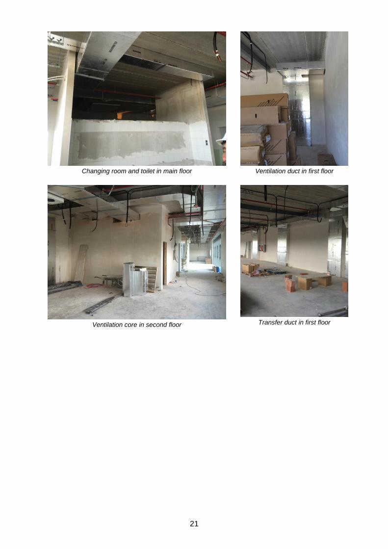
21
Changing room and toilet in main floor
Ventilation duct in first floor
Ventilation core in second floor
Transfer duct in first floor

22
12 Panning of ventilation, central unit information
The renovation was made considering the demands set by the regulations. It has been installed a
single heat recovery, the aim is to heat the entire building in periods of moderate demand with this
same air.
The heat recovery is of great flow caudal, Mod. Lufta maxk i3 7000DC PHI certified, which has been
placed on the roof and exchange the air of the entire building.
In the project we can differentiate two zones according to the use:
• Changing rooms used for 30 minutes during shift changes (3 shifts), 1.5 hours per day, plus a dining
hall that is used during one hour in each shift for a total of 3 hours a day;
• The rest of the building, whose supply air comes directly from the heat recovery unit.
Thus, as can be seen in the drawing, the supply air (in red), goes down through a vertical duct, from
the roof to the ground floor; two horizontal branches distribute this air around all the rooms on second
floor office, one of these branches continues to another air shaft where it is distributed vertically
around the east side of the first and main floor. Other branch goes down from the main duct to the first
and main floor in the west side.
Most of the office supply air (orange), passes through transfer to the changing and dining hall while a
small part returns to recovery. After passing through this rooms, transfer air reaches the return lines
(blue) to the heat recovery.
- Ventilation system model:
Lufta maxk i3 7000DC
- Effective heat recovery efficiency:
87%
- Electrical efficiency: 0,43 Wh/m3
The picture shows the heat recovery and the main ducks on the roof of the building.

23
13 Heat Supply
The heating network has been solved by two facility systems: one through the air ducts (hot / cold) and
the other a complementary Fan coils facility (hot / cold). The heat recovery unit is placed on the roof. It
has a battery placed at the outflow impulsion air ducts that is used to generate hot or cold air
according to demand.
The air (hot / cold) that flows through the ducts, get into the working spaces through the grids. When
the contribution made by them is not enough, Fan coils system start working, heating the water for
free. This is achieved because of the waste heat produced by the operation of the compressors
(located in the facility building, and used by the warehouse), that is recovered by the heat exchanger
placed at the compressor’s hot air outflow. This extra heat is the one that is used to heat for free the
hot sanitary and the Fan coils water.
Compressor unit in the facility building Heat exchanger into compressor´s hot air outflow

24
14 PHPP-Calculations
Casa Pasiva ComprobaciónFoto o dibujo Edificio:
Calle:
CP / Ciudad: Sector El Romaní. 46439. Sollana. Valencia
Provincia/País:
Tipo de edificio:
Datos climáticos: ud---01-Valencia rectificado PHI
Zona climática: 5: Cálido Altitud de la localización: 13 m
Prop. / cliente:
Calle:
CP / Ciudad: 09006 Burgos
Provincia/País:
Arquitectura: Instalaciones:
Calle: Calle:
CP / Ciudad: 09003 Burgos CP / Ciudad: 09003 Burgos
Provincia/País: Provincia/País:
Consultoría: Certificación:
Calle: Calle:
CP / Ciudad: CP / Ciudad:
Provincia/País: Provincia/País:
Año construcción: 2014 Temp. interior invierno [°C]: 20,0 Temp. interior verano [°C]: 25,0
Nr. de viviendas 1 Ganancias internas de calor (GIC); caso calefacción [W/m2]: 3,5 GIC caso refrigeración [W/m²]: 3,5
Nr. de personas: 79,0 Capacidad específica [Wh/K por m² de SRE]: 180 Refrigeración mecánica: x
Valores específicos referenciados a la superficie de referencia energética
Superficie de referencia energética m² 1145,1 Criterio ¿Cumplido?2
Calefacción Demanda de calefacción kWh/(m²a) 13 ≤ 15 -
Carga de calefacción W/m² 11 ≤ - 10
Refrigeración Demanda refrigera. & deshum. kWh/(m²a) 15 ≤ 15 15
Carga de refrigeración W/m² 12 ≤ - 11
Frecuencia de sobrecalentamiento (> 25 °C) % - ≤ - -
Frecuencia excesivamente alta humedad (> 12 g/kg) % 0 ≤ 10 Sí
Hermeticidad Resultado ensayo presión n50 1/h 0,3 ≤ 0,6 Sí
Demanda EP kWh/(m²a) 120 ≤ 120 Sí
Demanda PER kWh/(m²a) 57 ≤ - -
kWh/(m²a) 0 ≥ - -
2 Celda vacía: Falta dato; '-': No requerimiento
¿Casa Pasiva Classic? Sí
Función: Nombre: Apellido: Firma:
2-Certificador
ID Certificado Fecha emisión: Ciudad:
13/11/15
Bruno Gutiérrez Cuevas y Emilio Sánchez Quesada. EMMEPOLIS NOVECENTO SL
Calle santander 11, 3º 4
Sí
Sí
Criterios
alternativos
Dr. Wolfgang Feist
12176_PHI_PH_2015.11.13_MCR Darmstadt
REVISION PHI - OFICINAS GRUPO ANTOLIN VALPLAS
Calle de Casa Zuriaga sn
Valencia
GRUPO ANTOLÍN VALPLAS
ES-Spanien
Oficinas
ES-Spanien
Carretera Madrid Irún km 244,8
Ignacio Velázquez y Carlos Segura. EMMEPOLIS NOVECENTO SL
Calle santander 11, 3º 4
Passivhaus Institut
Confirmo que los valores aquí presentados han sido determinados siguiendo la metodología de PHPP y están basados en
los valores característicos del edificio. Los cálculos de PHPP están adjuntos a esta comprobación.
-
Energía Primaria no renovable (EP)
Energía Primaria
Renovable (PER) Generación de Energía
Renovable
The PHPP is an easy to use planning tool for energy efficiency for the use of architects and planning
experts. The reliability of the calculation results and ease of use of this planning tool has already been
experienced by several thousand users.
Passivhaus VALPLAS OFFICE PHPP- Calculation: According to developed tests in the building, the
data for heating demand is 13,37 kWh / (m2a) so that it gets the limit of 15kWh / (m2a). In terms of
primary energy demand also it complies with the limit established according to the standard of 120
kWh / (m2a) having 116 kWh / (m2a).

25
Energy balance, heating demand (monthly method)
PérdidasGanancias
Ganancias de calor no utilizables1,43
Muro ext. - aire ext. 5,11
Techo / cubierta - Aire ext. 2,96
Solera / losa piso / forjado sanitario1,75
Local calefactado 4,2
Ventanas 20,5
Pérdidas de calor por puentes térmicos1,12
Ventilación 3,17
ganancias solares de calor 11,7307304
ganancias internas de calor 15,204
demanda calefacción 13
Suma de control 40,2 40,2018768
0,0
13,3
15,2
11,7
3,2
1,10,0
20,5
4,2
0,00,0
1,8
3,0
0,0
5,1
1,4
0
5
10
15
20
25
30
35
40
45
Pérdidas Ganancias
Flu
jos d
e c
alo
r [k
Wh/(
m²a
)]Balance energético calefacción (método mensual)
Ganancias de calor no utilizables
Muro ext. - aire ext.
Techo / cubierta - Aire ext.
Solera / losa piso / forjado sanitario
Local calefactado
Ventanas
Pérdidas de calor por puentes térmicos
Ventilación
ganancias solares de calor
ganancias internas de calor
demanda calefacción
The biggest energy loss takes place through windows with the half of the total (20.5 kWh / (m2a)).
Almost the same amount of losses arise through the walls, with a similar value between roof, floors
and walls (5.1 -1.8 kWh / (m2a)). Moreover, a third of the necessary energy is provided by solar gains
which balance losses through windows. All this added to the internal gains (almost the 40% - 15.2
kWh / (m2a)), give us a result of heating demand of 30% of the losses, 13.3 kWh / (m2a).
15 Total Construction and Building costs
The building has been built for a private Group in the years of economic crisis but with slight growing
trend (2014/2015).
The Passivhaus VALPLAS Office has a total floor area of 1.436,43 m2 and 1.248,65 m2 floor space.
With a total construction cost of 1.186.289,63 €, the price per square meter of the building ended up
being de 825,86 € / m2.

26
16 Information about the architectural design
First Passivhaus office building certified in Spain, with an area of 1,436 m2 and three floors. The
bioclimatic design was vital to get the values obtained in the PHPP. Due to the north orientation and
the volume imposed by the conditions of the plot and the functional program. We have mainly worked
on optimizing hollows, trying to find a balance between the contributions of natural light and reducing
transmission losses. Its location, attached to the south of the existing warehouse facade, cuts off the
night cooling created by the natural cross ventilation. To reduce this demand, we have projected two
interior courtyards that also intensify the contribution of natural light.
The office building is a longitudinal prism 8.5 m wide by 59.5 m long and 3 stories high. It has a 3
heights patio in front of the access and another one of 2 heights, over the dressing room area that is
located in the main floor. These courtyards bring light to different meeting rooms.
The building has two distinct areas on the ground floor: Reception of the factory and office area, and
the service area of the factory staff. The remaining surface on the upper floors is completed by office
use.