Passivecontrol of the aeroelastic instability of a symmetric multi-body ... · Passivecontrol of...
10
Passive control of the aeroelastic instability of a symmetric multi-body sectional model Marco Lepidi, Giuseppe Piccardo Dipartimento di Ingegneria Civile, Chimica e Ambientale, Universit` a di Genova, Italy E-mail: [email protected], [email protected] Keywords: Multi-body system, aeroelastic stability, passive control, viscous coupling. SUMMARY. The aeroelastic stability of a multi-body system is studied through a four-degree-of- freedom model, which describes the linearized section dynamics of particular suspended bridges with doubly-symmetric cross-section, subject to a lateral stationary wind flow. A multi-parameter perturbation solution, applied to the classic modal problem in internal resonance conditions, allows a consistent reduction of the model dimensions. Focus is made on the particular parameter region corresponding to the triple internal resonance among a global torsional mode of the deck and two local modes of a pair of hanger cables. The bifurcation scenario described by an aeroelastic stabi- lity analysis is featured by two dynamic instability boundaries, strongly interacting to each other. The analysis of the critical wind velocity provides satisfying engineering results, pointing out how the presence of resonant light cables and the addiction of dissipative couplings, simulating passive viscous dampers acting on the cable-deck differential velocity, may have beneficial effects in preven- ting the aeroelastic instability of the multi-body system. 1 INTRODUCTION Dynamic analysis of two or more interconnected rigid or flexible bodies, also known as multi- body systems, is a topic of great interest with applications in a broad variety of engineering fields. On the other hand, section models have often been applied in wind engineering in order to perform aerodynamic stability analyses using the quasi-steady theory. The classic phenomenon of aerody- namic instability involving slender structures with noncircular cross-sections is called galloping [1]; it is classified as a velocity-dependent, damping-controlled instability, giving rise to transverse or torsional motions [2, 3]. The applicability of the quasi-steady theory has been deeply discussed [1, 4], and its employment for torsional oscillations is often judged inadequate to provide realistic results, even if it can succeed in predicting the onset of torsional galloping [1]. Despite its inherent shortcomings, the common use of this approach can still be justified by the valuable possibility to assess the system aerodynamic stability through standard static experimental tests. The present paper approaches the aeroelastic stability analysis of a multi-body four-degree-of- freedom model, which appears able to synthetically simulate the linearized dynamics of particular suspended bridges with doubly-symmetric cross-section. The original model formulation, focused on the internal mechanical interactions among the deck section (principal body) and a pair of pre- tensioned hanger cables (secondary bodies), caused by the geometric stiffness, is enriched to account for the aerodynamic coupling between the vertical flexion and torsion components of the deck mo- tion, owing to a stationary wind flow acting along the horizontal symmetry axis. Multi-parameter perturbation methods allow the asymptotic approximation of the system eigen- properties governing the undamped free linear dynamics. In particular regions of the parameter space, internal resonance conditions occur, involving global modes, dominated by the two compo- nents of the deck motion, and a pair of local modes, dominated by the cable transversal motion. Wi- thin this framework, the present work analyzes the unexplored effects of the cable-deck interactions 1
Transcript of Passivecontrol of the aeroelastic instability of a symmetric multi-body ... · Passivecontrol of...

Passive control of the aeroelastic instability of a symmetric multi-bodysectional model
Marco Lepidi, Giuseppe Piccardo
Dipartimento di Ingegneria Civile, Chimica e Ambientale, Universita di Genova, ItalyE-mail: [email protected], [email protected]
Keywords: Multi-body system, aeroelastic stability, passive control, viscous coupling.
SUMMARY. The aeroelastic stability of a multi-body system is studied through a four-degree-of-freedom model, which describes the linearized section dynamics of particular suspended bridgeswith doubly-symmetric cross-section, subject to a lateral stationary wind flow. A multi-parameterperturbation solution, applied to the classic modal problem in internal resonance conditions, allowsa consistent reduction of the model dimensions. Focus is made on the particular parameter regioncorresponding to the triple internal resonance among a global torsional mode of the deck and twolocal modes of a pair of hanger cables. The bifurcation scenario described by an aeroelastic stabi-lity analysis is featured by two dynamic instability boundaries, strongly interacting to each other.The analysis of the critical wind velocity provides satisfying engineering results, pointing out howthe presence of resonant light cables and the addiction of dissipative couplings, simulating passiveviscous dampers acting on the cable-deck differential velocity, may have beneficial effects in preven-ting the aeroelastic instability of the multi-body system.
1 INTRODUCTIONDynamic analysis of two or more interconnected rigid or flexible bodies, also known as multi-
body systems, is a topic of great interest with applications in a broad variety of engineering fields.On the other hand, section models have often been applied in wind engineering in order to performaerodynamic stability analyses using the quasi-steady theory. The classic phenomenon of aerody-namic instability involving slender structures with noncircular cross-sections is called galloping [1];it is classified as a velocity-dependent, damping-controlled instability, giving rise to transverse ortorsional motions [2, 3]. The applicability of the quasi-steady theory has been deeply discussed[1, 4], and its employment for torsional oscillations is often judged inadequate to provide realisticresults, even if it can succeed in predicting the onset of torsional galloping [1]. Despite its inherentshortcomings, the common use of this approach can still be justified by the valuable possibility toassess the system aerodynamic stability through standard static experimental tests.
The present paper approaches the aeroelastic stability analysis of a multi-body four-degree-of-freedom model, which appears able to synthetically simulate the linearized dynamics of particularsuspended bridges with doubly-symmetric cross-section. The original model formulation, focusedon the internal mechanical interactions among the deck section (principal body) and a pair of pre-tensioned hanger cables (secondary bodies), caused by the geometric stiffness, is enriched to accountfor the aerodynamic coupling between the vertical flexion and torsion components of the deck mo-tion, owing to a stationary wind flow acting along the horizontal symmetry axis.
Multi-parameter perturbation methods allow the asymptotic approximation of the system eigen-properties governing the undamped free linear dynamics. In particular regions of the parameterspace, internal resonance conditions occur, involving global modes, dominated by the two compo-nents of the deck motion, and a pair of local modes, dominated by the cable transversal motion. Wi-thin this framework, the present work analyzes the unexplored effects of the cable-deck interactions
1

on the aeroelastic stability of the entire system, as well as the possibility to employ passive dampersto enlarge the stability regions. To this purposes, the critical conditions are imposed on the reso-nant system, reduced to modal coordinates, to perform a local stability analysis leading to a stabilitychart in the extended parameter space including the wind mean velocity and all the damping terms.In particular, the influence of a slight detuning between the natural frequencies (nearly-resonant sy-stems) on the critical wind velocity is investigated. Furthermore, the effects of addictional dissipativecoupling, simulating viscous dampers, on the instability boundaries are discussed.
2 MULTI-BODY SECTIONAL MODELThe cable-deck structural interactions in a suspended or cable-stayed bridge typically involve
the three-dimensional deck motion and the transversal motion of one or more resonant hangers orstay cables. A dynamic multi-body model composed by a principal system (SP), represented by adoubly-symmetric rigid rectangular body, and a pair of secondary systems (SS1 and SS2), representedby identical point bodies (Figure 1a), can be effectively employed to synthetically reproduce thecomplex scenario of linear and nonlinear coupling among the rigid planar sections of the bridge deckand the flexible, pre-tensioned cables connecting them to the supporting system, namely the maincables (suspended bridges), the towers (cable-stayed bridges), or the superior arch (arch bridges) [5].
The dynamic configuration of the principal system is fully defined by the centroid vertical displa-cement V and rotation θ, while the horizontal displacement is assumed rigidly constrained (Figure1b). The elastic constant Kpi of the two linear springs (i=1,2) connecting the principal system to thelower ground simulate the flexural and torsional stiffness of the bridge deck. The height-to-widthratio of the rectangular shape and the material mass density can be independently varied to properlycapture the vertical Mp and rotational inertia Jp of the deck section. The dynamic configuration ofeach secondary system is described by its vertical Vi and horizontal displacement Ui (Figure 1b).Two springs connect each secondary system, with mass Ms , to the principal system and the upperground, simulating the anchorages to the deck and the (quite rigid) suspension system, respectively.The spring elastic constant Ksi (i=1,2) simulates the cable axial stiffness, whereas the geometricstiffness acting on the transversal cable motion can be accounted for by a spring prestress Hsi.
(a) (b) (c)
Ks
Hs1
Ks
Hs2
Ks
Hs1
Ks
Hs2
Kp1
Hp1
Kp2
Hp2
SS1 SS2
SP
Ls
Ls
Lp
AA
B
BV
θ
U1
V1
U2
V2 D
L
M
UA
UA
VA
θ
δA
θAVA
RAθ
V
where
θA(t)=δA(t)−θ(t)=atan
(−V +RAθ
UA
)−θ(t)
Figure 1: Multi-body system: (a) static and (b) dynamic configuration, (c) aerodynamic forces.
2

Moving from an exact kinematic formulation, the nonlinear equations governing the system dy-namics are obtained. These equations can be linearized around the initial prestressed configuration,whose static self-equilibrium, in the absence of dead external forces, requires the two conditionsHp1=Hs1=:H1 and Hp2=Hs2=:H2. The following nondimensional variables can be introduced
v=V
Ls, u1=
U1
Ls, u2=
U2
Ls, v1 =
V1
Ls, v2=
V2
Ls, τ =ωpt, where ω2
p =2Kp1
Mp(1)
whereas a minimal nondimensional set of independent geometric and elasto-dynamic parameters is
α=A
Ls, β =
B
Ls, δ=
Lp
Ls, %2 =
Ms
Mp, χ2=
Jp
MpL2s
, ω2v =
Kt
2Kp1, κ=
Kd
2Kp1, µ2
i =Hi
2Kp1Ls(2)
where Kt =2Kp1+Ks . Finally, accepting the reasonable assumption of small geometric-to-elasticstiffness ratio in the cables (H1,2 � KsLs), the vertical motion of the secondary systems can bestatically condensed in the low-frequency range of the system dynamics, in order to obtain a four-degree-of-freedom (4-dofs) model, in which the displacement vector is u = (v, θ, u1, u2)>. Underthe above considerations, the linear equation of motion governing the system forced response reads
Mu + Cu + Ku = f (u, u ) (3)
where the non-null coefficients of the mass matrix M and the stiffness matrix K are reported inthe Appendix. The (diagonal) viscous damping matrix C describes the mass-proportional structuraldamping. The aerodynamic forces f (u, u) are defined in the following paragraph.
2.1 Aerodynamic forcesThe stationary flow acting on the doubly-symmetric section can be physically characterized by
the air density dA and the mean wind velocity UA. Denoting with cd the sectional drag coefficient, c′`and c′m the first derivatives of the section lift and torsional moment coefficients (with respect to theangle of attack θA of the relative velocity VA, see Figure 1c), and defining BA a suitable referencelength of the cross-section and RA its characteristic radius [4], the aerodynamic forces assume thenon-dimensional simplified expressions (e.g. [2])
fA=−12kAuA
[uAc′`θ+
(c′d+c′`
)v−rA
(c′d+c′`
)θ]
(4)
mA=−12kAuAβAc′m
(uAθ+v−rAθ
)(5)
where the aerodynamic dimensionless quantities are defined as
βA=BA
Ls, uA=
UA
ωpLs, rA=
RA
Ls, %A =4
dAAB
Mp, kA=
14
βA
αβ%A (6)
Therefore, casting the displacement and velocity coefficients into the aerodynamic stiffness anddamping matrices CA and KA respectively, the non-dimensional linearized equation of motion (3)can be reformulated as:
Mu +(C+CA
)u +
(K+KA
)u = 0 (7)
where the non-zero terms of the matrices CA and KA are defined in the Appendix.
3

(a) (b) (c)
Figure 2: Typical modal properties: (a) global modes, (b),(c) local modes.
3 CLASSICAL MODAL ANALYSISNeglecting the aerodynamic forces and the structural damping, a classic modal analysis can be
performed. Decomposing the mass matrix in the form M = Q>Q (the decomposition is uniqueas the matrix M is diagonal), the real eigenvalues λ and eigenvectors ψ characterizing the freeundamped vibrations ensue from the solution of the standard eigenproblem
(G− λI
)φ = 0 (8)
whereφ=Qψ, and the equivalent stiffness matrix is G=Q−>KQ−1. The exact eigensolution locican be traced by solving the eigenproblem (9) throughout the whole technically relevant parameterrange, for instance recurring to numerical continuation techniques.
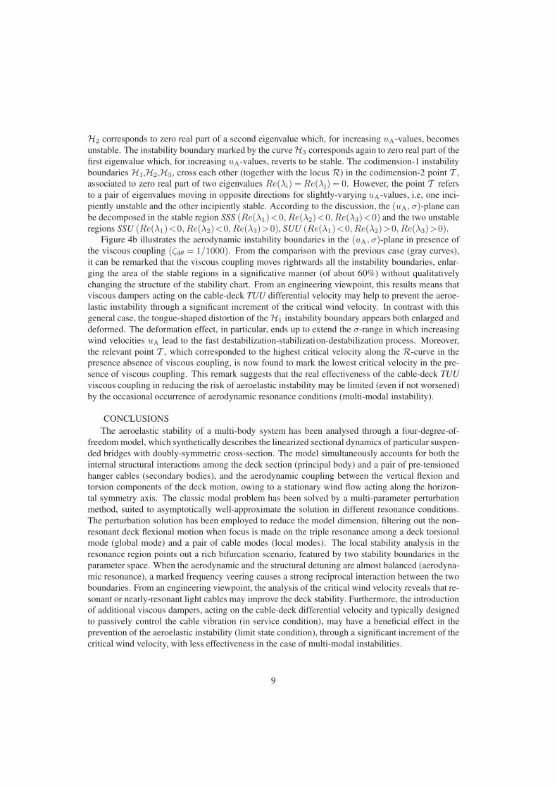
Parametric analyses of the solution show that a generic parameter set typically corresponds towell-distinct natural frequencies, related to modes dominated either by one of the principal systemcomponents of motion (global modes, Figure 2a), or by the horizontal displacement of one or boththe secondary systems (local modes, Figure 2b,c). Particular regions of the parameter space areinstead associated to internal resonance or nearly-resonance conditions, which correspond to iden-tical or close frequencies. Within these resonant regions the system eigensolution exhibits rapidmodifications under small changes of the varying parameters, that is, high eigensolution sensitivity.Therefore, care must be paid to the application of perturbation methods, which are nonetheless anattractive and powerful alternative to perform local parametric analysis within the resonant regions.
3.1 Perturbation solutionA perturbation approach to the solution of the eigenproblem requires a suited ordering of the
significant parameters, through the introduction of a small scaling parameter ε�1
α=εα, β =εβ, %2 =ε2%2 (1+εσ), χ2=ε2χ2, µ21=ε2µ2, µ2
2 =ε2µ2(1+εη), κ=εκ (9)
From a physical viewpoint, this parameter ordering in the multi-body system can be justified byengineering reasons, as it accounts for the lightness and transversal flexibility of the two cables(small %2 and µ2
1,2), which differ to each other for a slight pretension difference only (describedby the new parameter η), and the section flatness of the typical slender bridge deck (small α andβ), which are also characterized by small torsional inertia (small χ2). After the introduction of theparameter ordering and the expansion in ε-powers, the equivalent stiffness matrix reads
G=G0+εG1+O(ε2
)(10)
where the non null coefficients of the unperturbed stiffness G0 and the stiffness perturbation G1 arereported in the Appendix. It is worth noting that G0 is a diagonal matrix. Therefore the unpertur-bed system is composed of four independent oscillators, whose natural frequencies can be perfectly
4

tuned to each other by equating the diagonal terms, in order to obtain exact internal resonance con-ditions among one or more dofs. In particular, the zeroth-order frequencies of the two secondarysystems, described by identical oscillators, are certainly resonant. Distinguishing the frequencies ofthe vertical displacement (V) and rotation (T) of the principal system from those of the horizontaldisplacements (UU) of the secondary systems, the internal resonance conditions read
RVT :α2
χ2=1, RVUU : 2
µ2
%2=ω2
v, RTUU : 2µ2
%2=ω2
v
α2
χ2, RVTUU : 2
µ2
%2=ω2
v
α2
χ2=ω2
v (11)
where the tilde has been omitted. These conditions define the one or two-dimensional loci of theparameter space corresponding to exactly resonant unperturbed systems. When the stiffness pertur-bation G1 is added, the multi-body model moves within the sorrounding (narrow) parameter region,which corresponds to nearly-resonant systems, since small parameter modifications determine slightfrequency differences. To the specific purposes of this work, focus is made on the RTUU resonanceregion, by imposing the following relations among the parameters, equivalent to the condition (11)c
2µ2
%2=ω2
v
α2
χ2=: ω, Γ 2
v :=χ2
α26= 1 (12)
where ω is the triple frequency of the unperturbed system, and Γ 2v has to be supposed different, and
also sufficiently far, from unity. The resonant TUU sub-system can be isolated by the decomposition
G0=ω2
(Γ 2
v 00 I
), G1=ω2
(κ g>
1
g1 Gn1
), where Gn
1 =
dθ cθ cθ
cθ σ1 0cθ 0 σ2
, g1=
cv
00
(13)
where the synthetic notation adopted in the first-order perturbation sub-matrices g1 and Gn1
dθ = κα2
χ2+ 2β
%2
χ2, σ1 = −σ, σ2 = η − σ, cθ =
12β
%
χ, cv =
κ
Γvω2(14)
reflects the traditional distinction among disorder (dθ, σ1,2) and local or global coupling (cθ, cv).Employing a multi-parameter perturbation method suited to deal with multi-degrees-of-freedom
nearly-resonant systems [6],[8], the asymptotic expansion (at the first ε-power) of the eigenvaluematrix, uniformly valid in each parameter space direction, can be achieved
Λ=Λ0+εΛ1+O(ε2
), Λ0 =diag
(ω2, ω2, ω2, Γ 2
v ω2), Λ1 =diag
(λr
11, λr12, λ
r13, κ
)(15)
is found to well-approximate the exact eigensolution in the resonant region (Figure 3). The parame-tric form of the resonant eigenvalues λk =ω2+ελr
1k (k=1,2,3) is reported in the Appendix.If the eigenvector matrix is decomposed Φ= [Φr|Φs], where the 4-by-3 sub-matrix Φr collects
the resonant eigenvectors and the 4-by-1 sub-matrix Φs hosts the non-resonant mode, the asymptoticexpansion leads to the first-order approximation of the resonant sub-matrix (see also the Appendix)
Φr = Φr0 + εΦr
1 + O(ε2
), Φr
0 =(
0Φrn
0
), Φr
1 =(
Φrm1
Φrn1
)(16)
whose peculiar structure states that the TUU modal components (lower essential part Φrn0 ) represent
the dominant (zeroth-order) modal contribution, while the V modal component (upper complemen-tary part Φrm
0 ) offers just a minor (first-order) modal contribution.
5

-0.15 -0.10 -0.05 0.00 0.05 0.10 0.15
0.85
0.90
0.95
1.00
1.05
1.10
1.15
0.00 0.05 0.10 0.15 0.20 0.25 0.30
0.85
0.90
0.95
1.00
1.05
1.10
1.15
exact1st order2nd order
0-0.05
-0.10-0.15
0.15
0.100.05
0
0.1
0.2
0.3
0.9
1.0
1.1
1.2
(a) (b) (c)β
βη
η
λri
λriλr
i
λr2
λr2
λr2
λr3
λr3λr
3
λr1 λr
1λr
1
Figure 3: Comparison of the exact and approximated resonant eigenvalue lociin the (β, η)-space (for α=2/10, %2=1/400, χ2=1/36, σ=0).
4 AEROELASTIC STABILITY ANALYSISThe additional dissipation given by viscous dampers acting on the cable-deck relative motion,
often used to passively control the cable vibrations in suspended bridges, is added to the diagonaldamping matrix D=Q−>CQ−1 to replicate the structure of the stiffness matrix
D=(
ζv d>
d Dn
), where Dn =
ζθ 0 00 ζu 00 0 ζu
+
0 ζdθ ζdθ
ζdθ 0 0ζdθ 0 0
, d=
0ζdv
ζdv
(17)
and ζdθ and ζdv account for viscous dampers coupling the VUU and TUU dofs, respectively.Consistently with the ordering of the elasto-geometric parameters, the structural damping and
the aerodynamic terms can be ordered by setting (for subscript j=v,θ, u, k=dv, dθ)
ζj =εζj, ζk =εζk, rA=εrA, uA=εuA, kAuA=εkAuA (18)
according to which, the small to mid-range of wind flow velocities uA can be investigated. All theaerodynamic coefficients are supposed to be O(1), according to experimental measures.
After substitutions and expansion in ε-powers, the damping matrix D= εD+O(ε2
), while the
equivalent aerodynamic stiffness GA=Q−>KAQ−1 and damping matrix DA=Q−>CAQ−1 read
GA=εGA+O(ε2
), DA=εDA+O
(ε2
), GA=
(0 g>
A
0 GnA
), DA=
(ξv dm
A>
dnA Dn
A
)(19)
where the absence of zeroth-order terms states that the aerodynamic forces do not significantly alter,but only perturb the eigenproperties, namely the internal resonances. The sub-matrices read
GnA1=
gθ 0 00 0 00 0 0
, Dn
A1=
ξθ 0 00 0 00 0 0
, gA1=
gvθ
00
, dn
A1=
ξθv
00
, dm
A1=
ξvθ
00
(20)
where the following ε-order auxiliary parameters have been introduced (tilde omitted)
gθ = 12
kAuA
χ2βAuAc′m, gvθ = 1
2
kAuA
χuAc′`, ξv = 1
2kAuA
(c′d+c′`
), (21)
ξθ =−12
kAuA
χ2βArAc′m, ξvθ =−1
2
kAuA
χuA
(c′d+c′`
), ξθv = 1
2
kAuA
χβAc′m (22)
6

4.1 Reduced-order modelEmploying a classic Galerkin procedure, the displacement vector u is expressed as a linear com-
bination of the three resonant modes through the change-of-variable u=Φrq. Therefore, a reduced-order model, defined in the modal amplitudes q and valid in the resonant regions of the parameterspace, is obtained. The model response is governed by the equation of motion
Mq + Dq + Kq = 0 (23)
where the mass, stiffness and damping matrices follow from the coordinate change
M = Φr>Φr, D = Φr>(D+DA
)Φr, G = Φr>(
G+GA
)Φr (24)
According to the perturbation solution (15) and omitting the superscript r for the sake of simplicity,it can be demonstrated that the matrices can be consistently expressed as
M=Φn0>Φn
0 , D=εD1 = εΦn0>(
Dn1+Dn
A1
)Φn
0 , (25)
G = G0+εG1 = ω2Φn0>Φn
0+εΦn0>(
ω2Gn1+Gn
A1
)Φn
0 (26)
This result evidences a key-issue, which is worth of the following mechanical interpretation. Theperturbation solution of the classical modal problem (13)-(16) demonstrates how the free undampeddynamics of the three resonant TUU dofs is quasi-independent of the forth dof, as may be expected.Moreover, the 3dofs reduced-order model (23), defined in the amplitudes of the classic (real) resonantmodes to describe the aerodynamics of the resonant TUU sub-system, possesses the same (complex)eigenvalues of the initial 4dofs model (7), if the forth non-resonant dof is simply neglected. Fromthe mathematical viewpoint, this statement can be immediately proved by pre-multiplying and post-multiplying (7) by Φn
0−> and Φn
0−1, respectively. In practice, the first-order perturbation analysis
filters out the coupling between the resonant TUU sub-system and the remaining non -resonant dof.A major remark is that, since the perturbation analysis excludes the RV resonance (by setting Γv farfrom unity), the non-symmetric couplings, i.e. the aeroelastic stiffness and damping terms gvθ , ξvθ ,ξθv are filtered out, ensuring that the resonant TUU sub-system is non-defective.
4.2 Critical conditionsAccording to the above remarks, the aeroelastic stability analysis for the resonant TUU sub-
system can be based on the parameter-dependent loci of the eigenvalues λ which satisfy the equation
det[λ2I + λ
(Dn
1+DnA1
)+ ω2I +
(ω2Gn
1+GnA1
)]= 0 (27)
where all the ε-order terms are between parentheses. The incipient instability occurs for the criticalcondition Re(λi) = 0, corresponding to zero real part of the i-th eigenvalue (namely Hopf bifurca-tion). The critical wind velocity is the lowest destabilizing uA-value. Resorting to the numericalsolution of the characteristic equation, preliminary parametric analyses have been performed in thethree-dimensional parameter space spanned by the wind velocity uA and the small (σ, ζc)-values,with a twofold aim: first, to determine the role played by the two resonant secondary systems, eva-luating how this role can be also modified by a small internal detuning (due to the cable disorder σ)and, second, to check whether a dissipative coupling among the TUU dofs (described by the ζc-parameter) may have a positive effect in moving the instability threshold to higher uA-values. Froma wider perspective, these issues may attract a certain engineering interest focused on the suitabi-lity to neglect resonant, though non-massive, hanger cables in aerodynamic studies of suspendedbridges, and on the evaluation of the concurrent efficacy of viscous dampers, actually designed tomitigate the cable vibrations, in protecting also the bridge deck against wind-induced instabilities.
7

0.0 0.5 1.0 1.5 2.0 2.5 3.0
0.9
0.6
0.3
0.0
-0.3
-0.9
-0.6
0.9
0.6
0.3
0.0
-0.3
-0.9
-0.6
0.0 0.5 1.0 1.5 2.0 2.5 3.0
(a) (b)σ σ
uA uA
R R
H1
H1
H1
H1
H1
H1
T T
SSS
SSU
SSS
SSU
SUU
SSS
SSU
SSS
SSUH2H3
A-A
B-B
A-A
B-B
Figure 4: Aeroelastic stability boundaries in the (uA, σ)-plane for (a) ζc =0, (b) ζc =1/1000(ω=1, β =1/20, α=1/10, η=0, χ2=1/36, βA=1/20, kA=1/40, rA=1/40, c′m=2.46).
Figure 4a illustrates the aerodynamic instability boundaries in the (uA, σ)-plane in the absenceof viscous coupling (ζdθ =0), and fixed values of all the remaining parameters. The geometric andmechanical parameter are referred to typical bridge structures, while the aerodynamic coefficientshave been quantitatively assessed according to [7]. The critical wind velocity, along the stabilityboundary H1, is almost independent of the cable disorder σ, except for a narrow negative value-range, around σ =−0.4, where the curve exhibits a short and sharp right-oriented tongue, bendingdownwards. However, since the tongue moves the stability loss towards higher wind velocities uA,and though the results may be not exhaustive, it can be pointed out that resonant or nearly-resonantcables do not induce dangerous effects, since their small mass can improve but not worsen the deckinstability. With respect to the tongue-region, the local increment of the critical velocity can be rela-ted to the combination of the cable disorder σ and the uA-dependent aerodynamic stiffness. Indeed,the imaginary part of two eigenvalues mainly depends on the cable disorder σ, whose positive (ne-gative) values have a softening (stiffening) effect. On the contrary, the imaginary part of the thirdeigenvalue systematically grows up, only due to the stiffening effect of increasing wind velocitiesuA. Thus, a balance between the two simultaneous effects can occur only in the σ < 0 half-plane,if the increasing structural detuning caused by the cable disorder σ is compensated by the growingaerodynamic stiffness. Actually, a perfect balance between these competing effects (referred to asexact aerodynamic resonance) cannot occur, since the two approaching loci of the eigenvalue imagi-nary (real) part undergo a strict veering (crossing) phenomenon. This strong interaction phenomenoncauses the distortion of the instability boundary H1 when it intersects the crossing locus of the realparts of the eigenvalues Re(λi) = Re(λj), marked by the black dotted curve R. The distortionof the instability boundary H1 determines the local convexity of the stable region. Consequently,particular σ-values experiences three alternate change-in-sign of the eigenvalue real part, meaningthat increasing wind velocities determine a fast destabilization-stabilization-destabilization process(see for instance section B-B for σ =−0.41). At higher wind velocities uA and negative σ-values,additional boundaries exist, close to the R-curve. The instability boundary marked by the curve
8
H2 corresponds to zero real part of a second eigenvalue which, for increasing uA-values, becomesunstable. The instability boundary marked by the curve H3 corresponds again to zero real part of thefirst eigenvalue which, for increasing uA-values, reverts to be stable. The codimension-1 instabilityboundaries H1,H2,H3, cross each other (together with the locus R) in the codimension-2 point T ,associated to zero real part of two eigenvalues Re(λi) = Re(λj) = 0. However, the point T refersto a pair of eigenvalues moving in opposite directions for slightly-varying uA-values, i.e, one inci-piently unstable and the other incipiently stable. According to the discussion, the (uA, σ)-plane canbe decomposed in the stable region SSS (Re(λ1)<0, Re(λ2)<0, Re(λ3)<0) and the two unstableregions SSU (Re(λ1)<0, Re(λ2)<0, Re(λ3)>0), SUU (Re(λ1)<0, Re(λ2)>0, Re(λ3)>0).
Figure 4b illustrates the aerodynamic instability boundaries in the (uA, σ)-plane in presence ofthe viscous coupling (ζdθ = 1/1000). From the comparison with the previous case (gray curves),it can be remarked that the viscous coupling moves rightwards all the instability boundaries, enlar-ging the area of the stable regions in a significative manner (of about 60%) without qualitativelychanging the structure of the stability chart. From an engineering viewpoint, this results means thatviscous dampers acting on the cable-deck TUU differential velocity may help to prevent the aeroe-lastic instability through a significant increment of the critical wind velocity. In contrast with thisgeneral case, the tongue-shaped distortion of the H1 instability boundary appears both enlarged anddeformed. The deformation effect, in particular, ends up to extend the σ-range in which increasingwind velocities uA lead to the fast destabilization-stabilization-destabilization process. Moreover,the relevant point T , which corresponded to the highest critical velocity along the R-curve in thepresence absence of viscous coupling, is now found to mark the lowest critical velocity in the pre-sence of viscous coupling. This remark suggests that the real effectiveness of the cable-deck TUUviscous coupling in reducing the risk of aeroelastic instability may be limited (even if not worsened)by the occasional occurrence of aerodynamic resonance conditions (multi-modal instability).
CONCLUSIONSThe aeroelastic stability of a multi-body system has been analysed through a four-degree-of-
freedom model, which synthetically describes the linearized sectional dynamics of particular suspen-ded bridges with doubly-symmetric cross-section. The model simultaneously accounts for both theinternal structural interactions among the deck section (principal body) and a pair of pre-tensionedhanger cables (secondary bodies), and the aerodynamic coupling between the vertical flexion andtorsion components of the deck motion, owing to a stationary wind flow acting along the horizon-tal symmetry axis. The classic modal problem has been solved by a multi-parameter perturbationmethod, suited to asymptotically well-approximate the solution in different resonance conditions.The perturbation solution has been employed to reduce the model dimension, filtering out the non-resonant deck flexional motion when focus is made on the triple resonance among a deck torsionalmode (global mode) and a pair of cable modes (local modes). The local stability analysis in theresonance region points out a rich bifurcation scenario, featured by two stability boundaries in theparameter space. When the aerodynamic and the structural detuning are almost balanced (aerodyna-mic resonance), a marked frequency veering causes a strong reciprocal interaction between the twoboundaries. From an engineering viewpoint, the analysis of the critical wind velocity reveals that re-sonant or nearly-resonant light cables may improve the deck stability. Furthermore, the introductionof additional viscous dampers, acting on the cable-deck differential velocity and typically designedto passively control the cable vibration (in service condition), may have a beneficial effect in theprevention of the aeroelastic instability (limit state condition), through a significant increment of thecritical wind velocity, with less effectiveness in the case of multi-modal instabilities.
9

ACKNOWLEDGMENTSThis work has been partially supported by the Italian Ministry of Education, Universities and
Research (MIUR) through the PRIN funded program “Dynamics, Stability and Control of FlexibleStructures” [grant number 2010MBJK5B].
References[1] Paıdoussis M.P., Price S.J., de Langre E., “Fluid structure interactions - Cross-flow-induced
instabilities.” Cambridge University Press, NY, 2011.[2] Luongo A., Piccardo G., “Stabilita aeroelastica flesso-torsionale di sezioni doppiamente simme-
triche.” Atti del XIV Congresso AIMETA, Como, Italy, 1999.[3] Luongo A., Piccardo G., “Linear instability mechanisms for coupled translational galloping.”
Journal of Sound and Vibration, 288(4-5), 1027-1047 (2005).[4] Blevins R.D., “Flow-Induced Vibration.” Krieger Publishing Company, Florida 2001.[5] Lepidi M., Gattulli V., “A parametric multi-body system for linearized section model dynamics
of suspended and cable-stayed bridges.” J. Sound and Vibration, submitted.[6] Lepidi M., “Multi-parameter perturbation methods for the eigensolution sensitivity analysis of
nearly-resonant non-defective multi-degree-of-freedom systems.” Journal of Sound and Vibra-tion, 332(4), 1011-1032 (2013).
[7] Robertson I., Li L., Sherwin S., Bearman P.W., “A numerical study of rotational and transversegalloping rectangular bodies.” Journal of Fluids and Structures, 17(5), 681-699 (2003).
APPENDIXThe non-null coefficients Mij and Kij of the nondimensional 4-by-4 mass and stiffness matrices
M and K in equation (3) read
M11=1, M22 =χ2, M33,44=%2, K11=ω2v, K22=α2
(ω2
v+κ)+βµ2
θ (28)
K12=ακ, K23 = βµ21, K24 = βµ2
2, µ2θ =
(µ2
1+µ22
)(2+β+β/δ
)(29)
while the non-null coefficients KAij and CAij of the matrices KA and CA in equation (7) read
KA12= 12kAu2
Ac′`, KA22= 12kAu2
AβAc′m, CA11= 12kAuA(c′d+c′`), (30)
CA12= 12kAuAc′`, CA21= 1
2kAuAβAc′m, CA22= 12kAuAβArAc′m (31)
and finally the non-null coefficients Jij and Iij of the matrices G0 and G1 in equation (10) read
J11=ω2v, J22=ω2
v
α2
χ2, J33,44=2
µ2
%2, I11=κ, I22=κ
α2
χ2+ 4β
µ2
χ2, (32)
I33=−2σµ2
%2, I44=2(η−σ)
µ2
%2, I12=
α
χκ, I23,24=β
µ2
%χ. (33)
The perturbation form of the three resonant eigenvalues defined in (15) is
λrk = ω2 + ελr
1k = ω2 + 13
ε ω2[tr(Gn
1
)+ ∆ cos(Θk)
](34)
where the auxiliary parameters ∆ and Θk are
∆=√
6∥∥Gn
1− 13 tr
(Gn
1
)I∥∥, Θk= 1
3 arccos[2(k−1
)π+108∆−3 det
(Gn
1− 13 tr
(Gn
1
)I)]
(35)
10