Passive and Active Load Control for Wind Turbine...
39
AirfoilsforStructures AirfoilsforStructures - - Passive and Active Load ControlforWind Passive and Active Load ControlforWind Turbine Blades Turbine Blades C.P. van Dam Department of Mechanical & Aeronautical Engineering University of California, Davis
Transcript of Passive and Active Load Control for Wind Turbine...

Airfoils for StructuresAirfoils for Structures--Passive and Active Load Control for Wind Passive and Active Load Control for Wind Turbine BladesTurbine Blades
C.P. van DamDepartment of Mechanical & Aeronautical EngineeringUniversity of California, Davis
2
HAWT Size and Power Trends HAWT Size and Power Trends
3
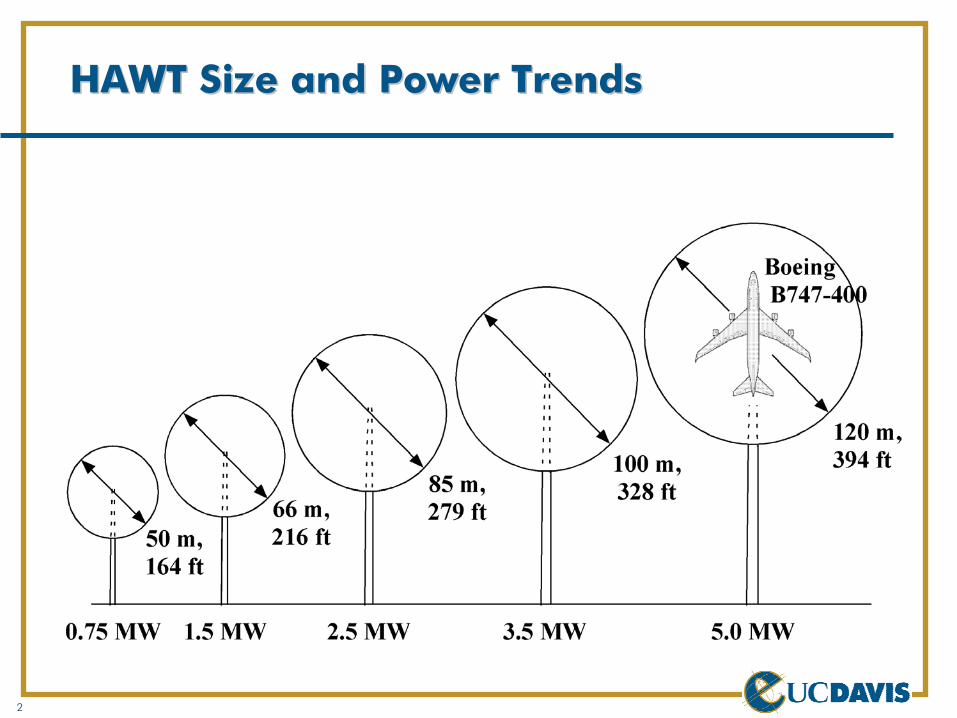
Novel approaches are needed to reduce growth in blade mass with blade length
Mass ∝ Length3 whereas Power ∝ Length2
Blade design methodology must be adapted to deal with resulting design challenges:
Past: Aero design Structural design
Required: Structural design Aero design
With design focus on turbine mass and cost for given performance, need may arise for passive and active techniques to control the flow and the loads on the blades/turbineTo maximize the overall system benefits of these techniques, load control should be included from the onsetThis presentation will summarize passive and active flow/load control techniques with a focus on our activities in these areas
MotivationMotivation

4
AcknowledgmentsAcknowledgments
UC DavisKevin StandishEddie MaydaJonathan BakerLorena Morenoet al
Dora Yen Nakafuji, LLNLKevin Jackson, Dynamic Design Engineering, Inc.Mike Zuteck, MDZ ConsultingDerek Berry, TPI Composites, Inc.Wind Energy Technology Group, Sandia National Laboratories
5
OutlineOutline
Passive flow/load controlOverview of conceptsBlunt trailing edge/flatback airfoils
Active flow/load controlOverview of conceptsMicrotab concept
Concluding remarks
6
Passive Flow/Load ControlPassive Flow/Load Control
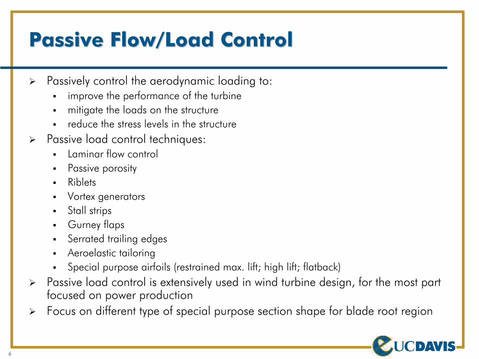
Passively control the aerodynamic loading to: improve the performance of the turbinemitigate the loads on the structurereduce the stress levels in the structure
Passive load control techniques:Laminar flow controlPassive porosityRibletsVortex generatorsStall stripsGurney flapsSerrated trailing edgesAeroelastic tailoringSpecial purpose airfoils (restrained max. lift; high lift; flatback)
Passive load control is extensively used in wind turbine design, for the most part focused on power productionFocus on different type of special purpose section shape for blade root region

7
Airfoil Thickness StudyAirfoil Thickness Study
Baseline airfoil is S821 (t/c = 24%)Camber distribution is constantMaximum thickness ratio is systematically increased from 0.24 to 0.60MSES used for aerodynamic analysis

8
Thickness Effect on LiftThickness Effect on LiftRe = 4.35 x 10Re = 4.35 x 1066, MSES, MSES
Transition free (Clean surface) Transition fixed (Soiled surface)
-0.5
0
0.5
1
1.5
2
-5 0 5 10 15 20
Re = 4.35 million, M � = 0.1, transition free
S821S821-30S821-35S821-40S821-45S821-50S821-55S821-60
Lift
coef
ficie
nt
Angle of attack, deg
-0.5
0
0.5
1
1.5
2
-5 0 5 10 15 20
Re = 4.35 million, M � = 0.1, transition fixed
S821
S821-30
S821-35
S821-40
Lift
coef
ficie
nt
Angle of attack, deg

9
Thickness Effect ConclusionsThickness Effect Conclusions
Loss in maximum lift due to surface roughness is encountered for airfoils with t/c > approx. 0.26At clean surface conditions, maximum lift coefficient peaks at t/c = 0.35 and lift-to-drag ratio peaks at t/c = 0.30Results back general view that maximum thickness ratios greater than 26% are deemed to have unacceptable performance characteristicsOne way to improve performance characteristics of thick airfoils is by installing vortex generators on suction surfaceAre there any other options?
10
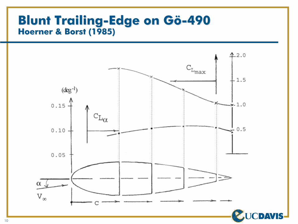
Blunt TrailingBlunt Trailing--Edge on GöEdge on Gö--490490HoernerHoerner & & BorstBorst (1985)(1985)
11
WortmannWortmann FXFX--7777--WW--xxx Truncated Airfoils xxx Truncated Airfoils TimmerTimmer (1992)(1992)
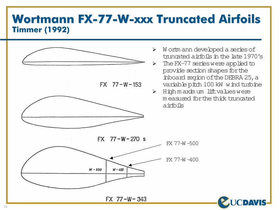
Wortmanndeveloped a series of truncated airfoils in the late 1970’sThe FX-77 series were applied to provide section shapes for the inboard region of the DEBRA 25, a variable pitch 100 kW wind turbineHigh maximum lift values were measured for the thick truncated airfoils
FX 77-W-400
FX 77-W-500
12
TR Series AirfoilsTR Series Airfoils
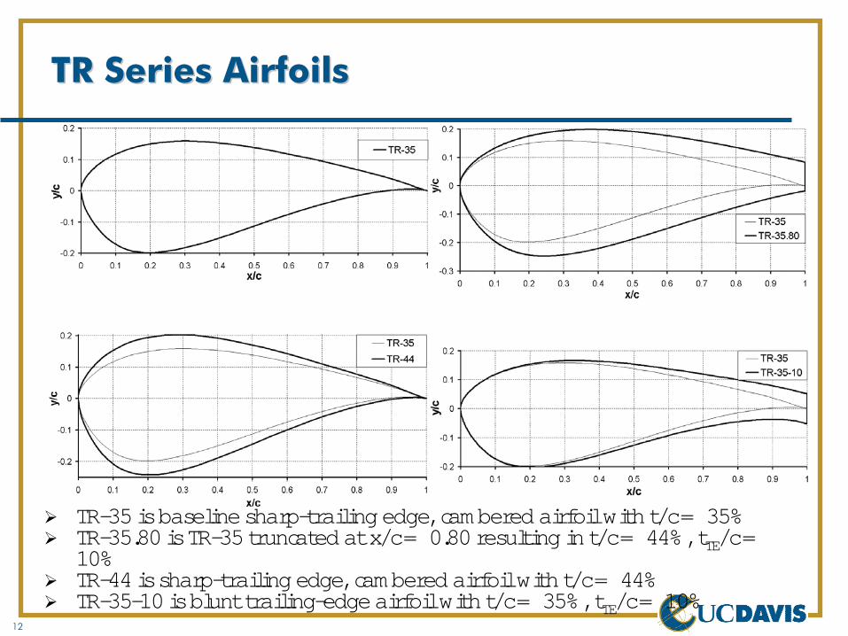
TR-35 is baseline sharp-trailing edge, cambered airfoil with t/c = 35%TR-35.80 is TR-35 truncated at x/c = 0.80 resulting in t/c = 44%, tTE/c= 10%TR-44 is sharp-trailing edge, cambered airfoil with t/c = 44%TR-35-10 is blunt trailing-edge airfoil with t/c = 35%, tTE/c= 10%
13
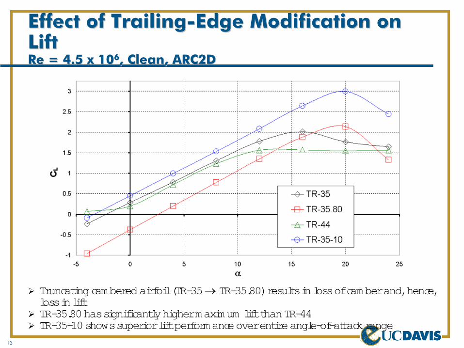
Effect of TrailingEffect of Trailing--Edge Modification on Edge Modification on LiftLiftRe = 4.5 x 10Re = 4.5 x 1066, Clean, ARC2D, Clean, ARC2D
Truncating cambered airfoil (TR-35 → TR-35.80)results in loss of camber and, hence, loss in liftTR-35.80 has significantly higher maximum lift than TR-44TR-35-10 shows superior lift performance over entire angle-of-attack range
14
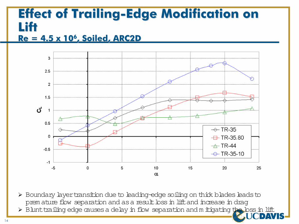
Effect of TrailingEffect of Trailing--Edge Modification on Edge Modification on LiftLiftRe = 4.5 x 10Re = 4.5 x 1066, Soiled, ARC2D, Soiled, ARC2D
Boundary layer transition due to leading-edge soiling on thick blades leads to premature flow separation and as a result loss in lift and increase in dragBlunt trailing edge causes a delay in flow separation and mitigating the loss in lift
15
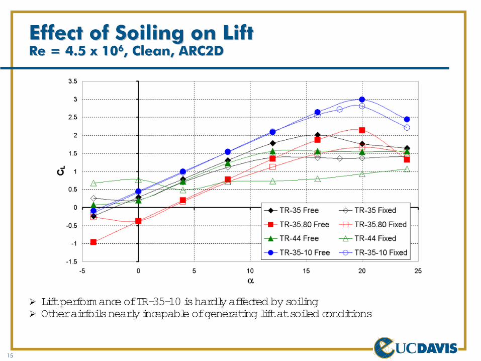
Effect of Soiling on LiftEffect of Soiling on LiftRe = 4.5 x 10Re = 4.5 x 1066, Clean, ARC2D, Clean, ARC2D
Lift performance of TR-35-10 is hardly affected by soilingOther airfoils nearly incapable of generating lift at soiled conditions
16
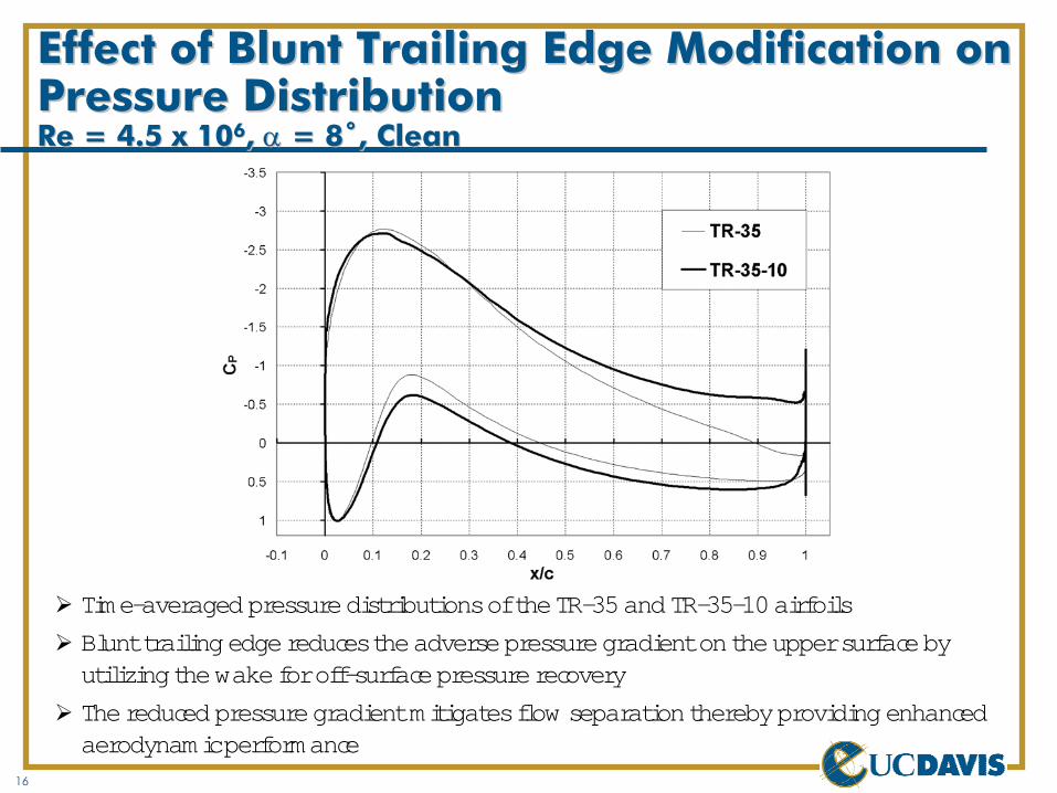
Effect of Blunt Trailing Edge Modification on Effect of Blunt Trailing Edge Modification on Pressure DistributionPressure DistributionRe = 4.5 x 10Re = 4.5 x 1066, , αα = 8˚, Clean= 8˚, Clean
Time-averaged pressure distributions of the TR-35 and TR-35-10 airfoils
Blunt trailing edge reduces the adverse pressure gradient on theupper surface by utilizing the wake for off-surface pressure recovery
The reduced pressure gradient mitigates flow separation thereby providing enhanced aerodynamic performance

17
Passive Flow/Load Control ConclusionsPassive Flow/Load Control Conclusions
Passive control is used extensively in the design of wind turbine bladesOne example of flow control for the blade root region of large wind turbine blades is the blunt trailing edge (or flatback) airfoil conceptThe incorporation of a blunt trailing edge for thick airfoils is beneficial for following reasons:
Improves aerodynamic lift performance (CLmax, CLα, reduced sensitivity to transition)Allows for very thick sections shapes to be used (t/c >> 30%) → lower stress levels in structureReduced chord for given maximum thickness can mitigate large blade transportation constraints
Trailing edge may need to be treated for reduction of base drag, flow unsteadiness and noiseTruncation of cambered section shapes is not a good idea because it leads to changes in camber and maximum thickness-to-chord ratio resulting in reduced lift performance

18
Blade System Design Study (BSDS) Blade System Design Study (BSDS) --Phase I (TPI Composites, Inc.)Phase I (TPI Composites, Inc.)
Design for sim ple structures before finalizing the aerodynam ic design
Constant spar cap, constant spar width design
Inboard the blades used high thickness flatback inboard airfoils
O utboard high lift airfoils with m odified thickness for thickness and shape to yield the least com plex and costly internal blade structure

19
Blade System Design Study (BSDS) Blade System Design Study (BSDS) --Phase I (TPI Composites, Inc.)Phase I (TPI Composites, Inc.)
Use of high thickness flatback airfoils in the inner blade, com bined with the use of IEC Class III design loads, results in a large reduction in blade prim ary structure for given power output perform ance
Resulting blade designs are significantly lighter than the latest designs in the m arketplace
Blade Mass (kg)

20
OnOn--Going/Future EffortsGoing/Future Efforts
Wind tunnel verification of blunt trailing edge airfoil performance is neededEvaluate 3-D flow effects and trailing edge treatments for reduction of base drag, flow unsteadiness, and noiseFlow control to control bluff body vortex shedding?

21
Active Flow/Load ControlActive Flow/Load Control
Actively control the loading on blade/turbine by modifying:Blade incidence angleFlow velocityBlade sizeBlade aerodynamic characteristics through:
Changes in section shapeSurface blowing/suctionOther flow control techniques
Active load control:May remove fundamental design constraints for large benefitsThese large benefits are feasible if active control technology is considered from the onset
Active load control is already used in wind turbine design. E.g.:Yaw controlBlade pitch controlBlade aileron
Provide fast system response to alleviate load spikes due to gusts
22
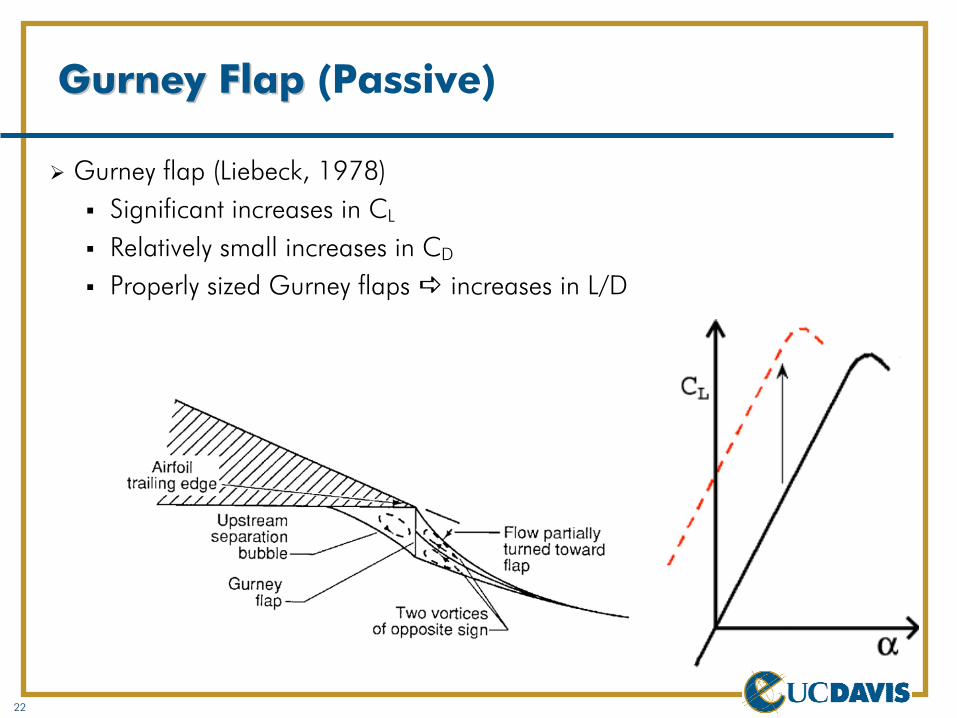
Gurney Flap Gurney Flap (Passive)
Gurney flap (Liebeck, 1978)Significant increases in CL
Relatively small increases in CD
Properly sized Gurney flaps increases in L/D
23
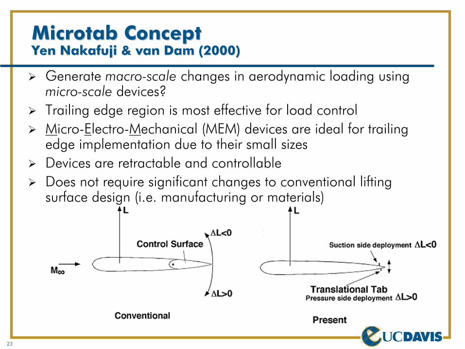
MicrotabMicrotab ConceptConceptYen Yen NakafujiNakafuji & van Dam (2000)& van Dam (2000)
Generate macro-scale changes in aerodynamic loading using micro-scale devices?Trailing edge region is most effective for load controlMicro-Electro-Mechanical (MEM) devices are ideal for trailing edge implementation due to their small sizes Devices are retractable and controllableDoes not require significant changes to conventional lifting surface design (i.e. manufacturing or materials)

24
MEMS MEMS MicrotabMicrotab CharacteristicsCharacteristics
Small, simple, fast responseRetractable and controllableLightweight, inexpensiveTwo-position “ON-OFF” actuationLow power consumptionNo hinge momentsExpansion possibilities (scalability)Do not require significant changes to conventional lifting surface design (i.e. manufacturing or materials)
25
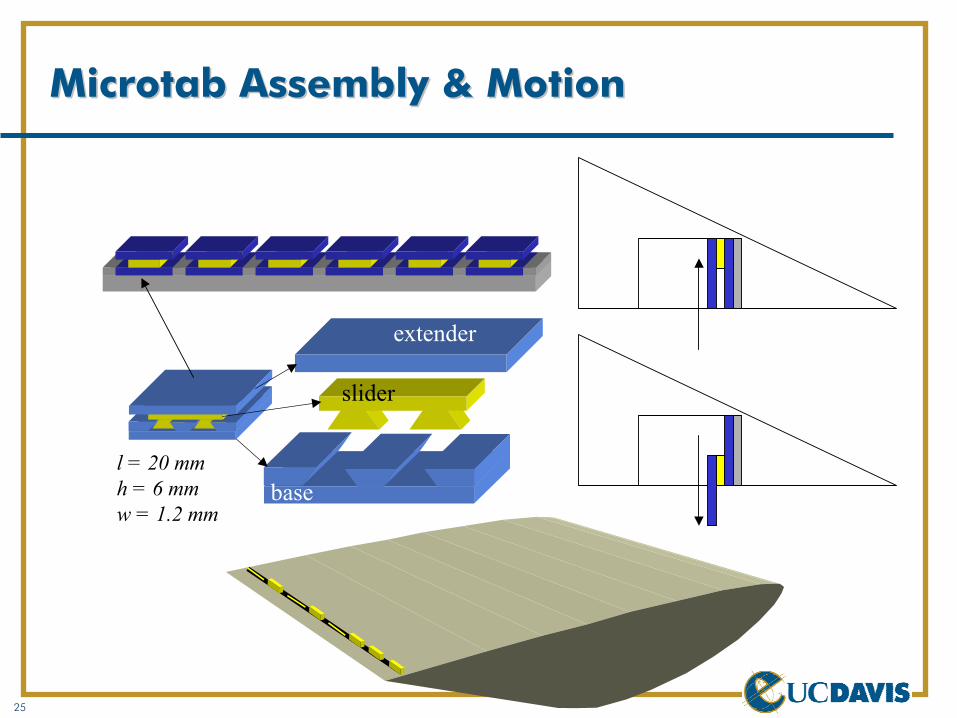
MicrotabMicrotab Assembly & MotionAssembly & Motion
slider
base
extender
l = 20 mmh = 6 mmw = 1.2 mm

26
Previous Testing & ResultsPrevious Testing & Results
Integrated Microtab ModelFixed Solid Tab Model
27
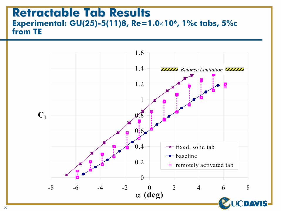
Retractable Tab ResultsRetractable Tab ResultsExperimental: GU(25)-5(11)8, Re=1.0×10⁶, 1%c tabs, 5%c from TE
0
0.2
0.4
0.6
0.8
1
1.2
1.4
1.6
-8 -6 -4 -2 0 2 4 6 8α (deg)
Cl
fixed, solid tabbaselineremotely activated tab
Balance Limitation
28
Continued Research Using Continued Research Using Computational Fluid Dynamics (CFD)Computational Fluid Dynamics (CFD)
Experimental testing is expensive and time consuming. The UC Davis wind tunnel is limited to:
Low-speed subsonic conditionsMaximum Reynolds number ≈1×10⁶
Advantages of CFD:Relatively fast and inexpensive to study a large number of geometric variationsProvides detailed insight to the flow-field phenomenaProvides better overall flexibility
29
Test AirfoilTest Airfoil
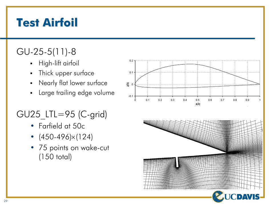
GU-25-5(11)-8High-lift airfoilThick upper surfaceNearly flat lower surfaceLarge trailing edge volume
GU25_LTL=95 (C-grid)• Farfield at 50c• (450-496)×(124)• 75 points on wake-cut
(150 total)

30
MicrotabMicrotab Effect on Flow DevelopmentEffect on Flow Development
Changes in the Kutta condition lead to an effective increase/decrease in cam ber

31
Effect of Lower Surface Tab on LiftEffect of Lower Surface Tab on LiftRe=1.0×10⁶, M∞=0.2, xtr=0.455

32
Effect of Lower Surface Tab on L/DEffect of Lower Surface Tab on L/DRe=1.0×106, M∞=0.2, xtr=0.455
33
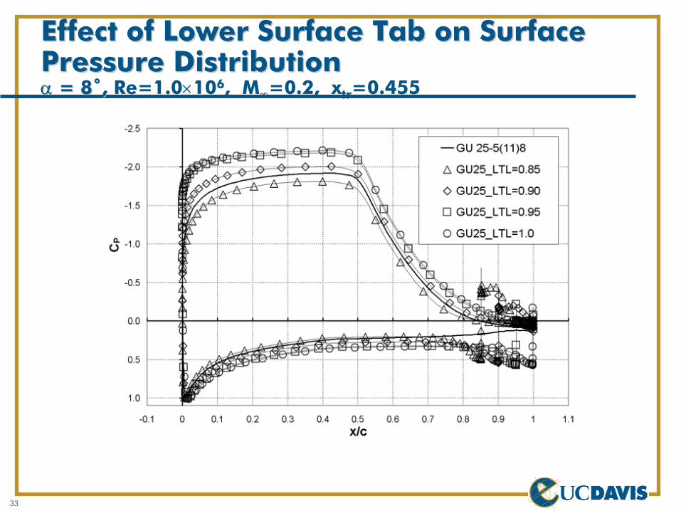
Effect of Lower Surface Tab on Surface Effect of Lower Surface Tab on Surface Pressure DistributionPressure Distributionαα = 8˚, = 8˚, Re=1.0×10⁶, M∞=0.2, xtr=0.455
34
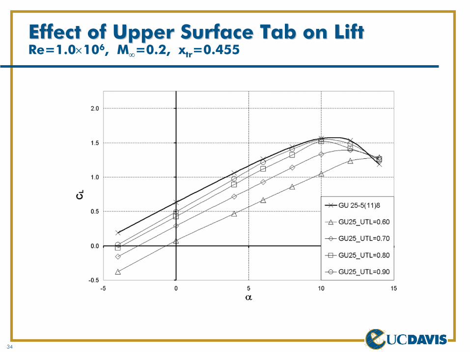
Effect of Upper Surface Tab on LiftEffect of Upper Surface Tab on LiftRe=1.0×10⁶, M∞=0.2, xtr=0.455
35
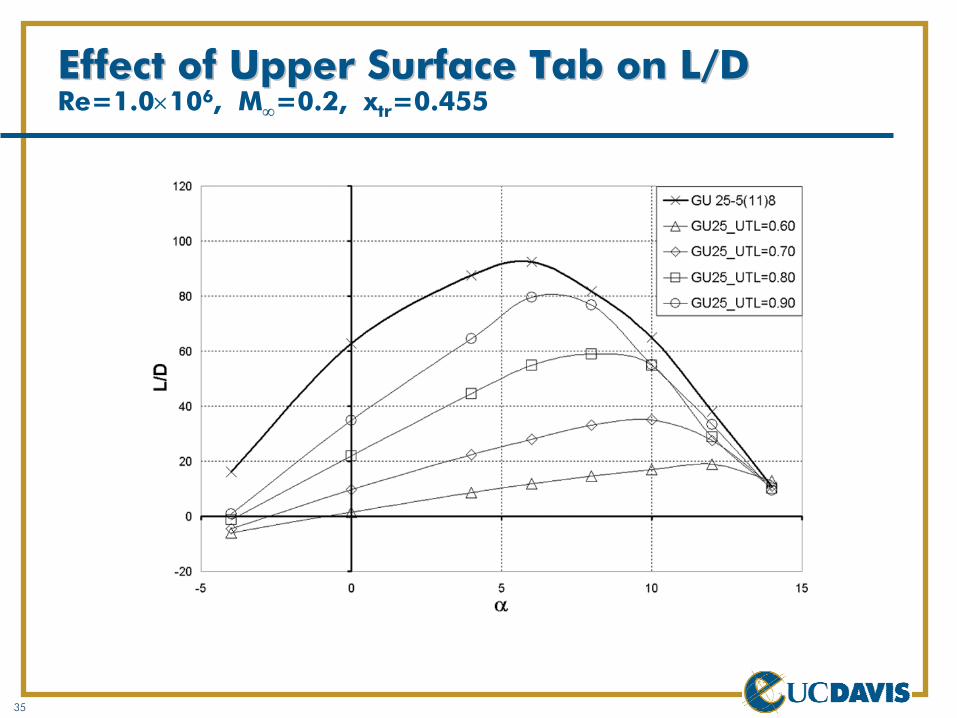
Effect of Upper Surface Tab on L/DEffect of Upper Surface Tab on L/DRe=1.0×106, M∞=0.2, xtr=0.455
36
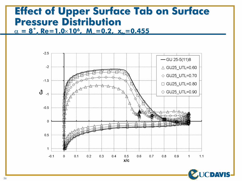
Effect of Upper Surface Tab on Surface Effect of Upper Surface Tab on Surface Pressure DistributionPressure Distributionαα = 8˚, = 8˚, Re=1.0×10⁶, M∞=0.2, xtr=0.455
37
Active Flow/Load Control ConclusionsActive Flow/Load Control Conclusions
Active flow/load control has been used in the design of wind turbine blades (active pitch, ailerons)A new form of active control for large wind turbine blades is the microtab conceptMicrotabs are an effective means of fast load control (load enhancement and mitigation)Microtabs remain effective when located forward from the trailing edgeFocus of work presented in this presentation is on a flow control actuator. Compete active load control system requires:
SensorsActuatorsControl algorithm
38
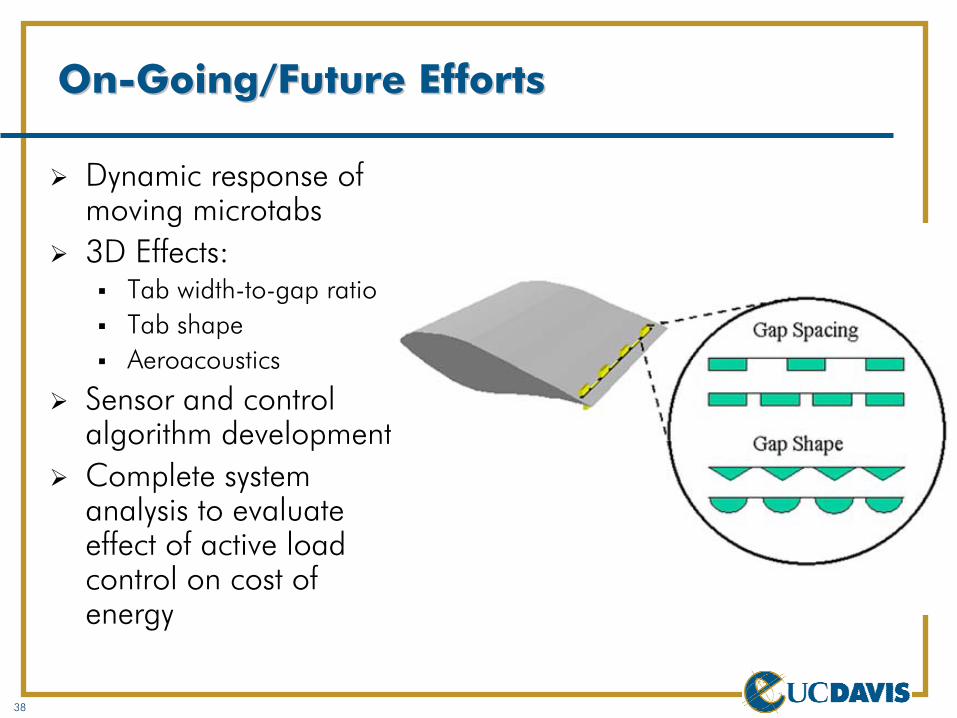
OnOn--Going/Future EffortsGoing/Future Efforts
Dynamic response of moving microtabs3D Effects:
Tab width-to-gap ratioTab shapeAeroacoustics
Sensor and control algorithm developmentComplete system analysis to evaluate effect of active load control on cost of energy
39
More InformationMore Information
TPI Com posites, “Param etric Study for Large W ind Turbine Blades,” SAN D2002-2519, August 2002.
TPI Com posites, “Cost Study for Large W ind Turbine Blades,” SAN D2003-1428, M ay 2003.
TPI Com posites, “Innovative Design Approaches for Large W ind Turbine Blades,” SAN D2003-0723, M arch 2003.
TPI Com posites, “Innovative Design Approaches for Large W ind Turbine Blades – Final Report,” SAN D2004-xxxx, in print.
K.J. Standish, C.P. van Dam , "Aerodynam ic Analysis of Blunt Trailing Edge Airfoils," Journal of Solar Energy Engineering, Vol. 125, N ov. 2003, pp. 479-487.
K.J. Standish, C.P. van Dam , "Com putational Analysis of a M icrotab-Based Aerodynam ic Load Control System for Rotor Blades," AHS Fourth Decennial Specialists’ Conference on Aerom echanics, San Francisco, CA, Jan. 2004.
D.T. Yen N akafuji, C.P. van Dam , R.L.Sm ith, S.D. Collins, "Active Load Control for Airfoils Using M icrotabs," Journal of Solar Energy Engineering, Vol. 123, N ov 2001, pp. 282-289.
C.P. van Dam , D.T. Yen, R.L. Sm ith, R.L., and S.D. Collins, "M icrofabricatedTranslational Stages for Control for Aerodynam ic Loading," U.S. Patent Application 20030218102, Filed April 2003.