PASSENGER VESSEL OPERATIONS AND DAMAGED STABILITY STANDARDS
39
TP 10943E (10/2007) PASSENGER VESSEL OPERATIONS AND DAMAGED STABILITY STANDARDS (Non-Convention Vessels) 2 nd EDITION OCTOBER 2007 TC-1002410 *TC-1002410*
Transcript of PASSENGER VESSEL OPERATIONS AND DAMAGED STABILITY STANDARDS

TP 10943E(10/2007)
PASSENGER VESSEL OPERATIONS AND DAMAGED STABILITY STANDARDS (Non-Convention Vessels) 2nd EDITION OCTOBER 2007
TC-1002410
*TC-1002410*

Responsible Authority Approval
The Director of Design, Equipment and Boating Safety is responsible for this document, including any change, correction, or update.
Victor Santos-Pedro Director
Design, Equipment and Boating Safety
Original Date Issued: 1991 Date Revised: 2008-02-11
© Her Majesty the Queen in Right of Canada, as represented by the Minister of Transport 1991.
Permission is granted, by Transport Canada, to copy this TP 10943E as required. While use of this material has been authorized, Transport Canada shall not be responsible for the manner in which the information is presented, nor for any interpretations thereof. This TP 10943E may not be updated to reflect amendments made to the original content. For up-to-date information, contact Transport Canada.
TP 10943E (10/2007)
TC-1002410
i
DOCUMENT INFORMATION Title Passenger Vessel Operations and Damaged Stability Standards (Non-convention vessels)
TP No. 10943E Edition 2nd Edition
Catalogue No. T29-29/2007E ISBN 978-0-662-47042-7
Originator Telephone 613-998-0650
Fax 613-991-4818
E-mail [email protected]
Design, Equipment and Boating Safety (AMSR) Tower C, Place de Ville 330 Sparks Street, 11th floor Ottawa, Ontario K1A 0N8 URL http://www.tc.gc.ca/MarineSafety
REVISIONS Last Review
Next Review
Revision No. Date of Issue Affected Pages Author(s) Brief Description of Change
0 1991-04-01 First Edition
1 1992-04-01 Part II, pages 8 & 9
2 2007-10-01 All 2nd Edition - Title modified “Ship” replaced with “vessel” Preamble: 3. modified, 3.1 to 3.4 added Interpretation: “New vessel”, “Undecked vessel”, “Ro-Ro passenger vessel” Part I: 1.(1) modified Part II: Part renewed completely Part III: 20.(3) added Part IV: Old 13.(4) & (5) deleted Part III to VII: sections renumbered Annex 1 added
3 2008-02-11 Changes in template 1. "New vessel": (e),(f),(g) and (h) corrected to read (a),(b),(c) and (d) Annex A: section number 7 to 13 corrected to read 1 to75

TABLE OF CONTENTS
PREAMBLE ..........................................................................................................1
INTERPRETATION.............................................................................................3
PART I....................................................................................................................5
GENERAL .................................................................................................................... 5 Application.............................................................................................................................. 5 Equivalents.............................................................................................................................. 5 Submission of Plans and Data................................................................................................. 5
PART II ..................................................................................................................6
DAMAGED STABILITY ............................................................................................ 6 Application.............................................................................................................................. 6 Standard of Subdivision – All Vessels.................................................................................... 7 Stability in Swamped Condition ............................................................................................. 8 Stability of Passenger Vessels in Damaged Condition – All Vessels ..................................... 8 Sufficiency of Stability in Damaged Condition – New Vessels.............................................. 9 Sufficiency of Stability in Damaged Condition – Existing Vessels...................................... 10 Principles for Calculations .................................................................................................... 10 COMPLIANCE SCHEDULE FOR EXISTING VESSELS ................................................ 13 Alternative Compliance Approach for Existing Vessels....................................................... 14 Alternative Compliance Approach for Vessels Built after 1 January 2009........................... 14
PART III...............................................................................................................15
LIGHTSHIP SURVEY .............................................................................................. 15 Application............................................................................................................................ 15 Lightship Survey................................................................................................................... 15
PART IV...............................................................................................................16
DOCUMENTATION ................................................................................................. 16 Application............................................................................................................................ 16 Stability Information ............................................................................................................. 16
ii

PART V ................................................................................................................17
WATERTIGHT AND WEATHERTIGHT INTEGRITY ..................................... 17 Application............................................................................................................................ 17 Closure of Cargo Loading Doors .......................................................................................... 17
PART VI...............................................................................................................18
DAMAGE PREVENTION AND CONTROL ......................................................... 18 Application............................................................................................................................ 18 Monitoring of Cargo Loading and Shell Doors..................................................................... 18
PART VII .............................................................................................................19
SUPPLEMENTARY EMERGENCY LIGHTING ................................................. 19 Application............................................................................................................................ 19 Supplementary Emergency Lighting..................................................................................... 19
APPENDIX 1 .......................................................................................................20
1. PRINCIPLES................................................................................................................ 21 2. OVERVIEW................................................................................................................. 21 3. STAGE 1 APPROACH................................................................................................ 23 4. STAGE 2 APPROACH................................................................................................ 23 5. STAGE 3 APPROACH................................................................................................ 25 6. MONITORING AND AUDIT ..................................................................................... 26
ANNEX A.................................................................................................................... 27 1. RISK MANAGEMENT PLAN.................................................................................... 27 2. Vessel documentation................................................................................................... 27 3. Training ........................................................................................................................ 28 4. Record Keeping............................................................................................................ 28 5. Data sources ................................................................................................................. 28 6 Monitoring and control................................................................................................. 29
ANNEX B .................................................................................................................... 29 STABILITY ANALYSIS METHODOLOGY ..................................................................... 29 1. Introduction .................................................................................................................. 29 2. Basic Calculation Approach ......................................................................................... 30 3. Application to Risk Assessment ................................................................................... 31
iii

Passenger Vessel Operations and Damaged Stability Standards (Non-convention vessels) TP 10943E 1 of 33
PREAMBLE
1. Recognizing that present Canadian regulations applicable to passenger vessels do not incorporate the latest international requirements, Transport Canada Marine Safety has adopted the following Standards for the design and operation of Canadian registered non convention passenger vessels pursuant to paragraph 10(1)(b) of the Canada Shipping Act 2001.
2. These Standards are based upon amendments to the International Convention for the Safety of Life at Sea (SOLAS) 1974, and the Protocol of 1978 relating thereto. These amendments, adopted by the Maritime Safety Committee (MSC) of the International Maritime Organization (IMO) on 21 April 1988 as Resolution MSC. 11(55) and on 28 October, 1988 as Resolution MSC. 12(56), are intended to enhance the safety of passenger vessels by defining standards of residual damage stability, and by ensuring that a stability assessment of a vessel's condition prior to sailing can be readily performed by vessel personnel. The operation of cargo loading doors and monitoring of enclosed ro ro cargo and special category spaces to ensure the maintenance of the watertight integrity of a vessel are also addressed, as well as supplementary emergency lighting requirements.
3. SOLAS Chapter II 1, Regulation 8 specifies the damaged stability requirements for passenger vessels to which the above amendments apply. These requirements have been used for Part II of these Standards, which supersedes the corresponding sections of Part I and Part II (and associated Schedule II) of the Hull Construction Regulations for those vessels to which these Standards apply. Regulations 8-1 extend the application of Regulation 8 to existing Ro-Ro passenger vessels. Regulations 8-2 and 8-3 introduce the requirements for a two-compartments standard of subdivision of Ro-Ro and non Ro-Ro vessels carrying 400 persons or more.
3.1 The SOLAS criteria have been adapted in Part II for application on existing vessels and on vessels operating in more protected waters based on a risk analysis. For smaller vessels, alternative compliance standards have been introduced.
3.2 An alternative compliance option based on the Static Equivalent Method (SEM) is also available for exiting Ro-Ro vessels.
3.3 For new vessels built after 1 January 2009 the new SOLAS probabilistic method introduced by Resolution MSC.194(80) adopted on 20 May 2005 may also be applied for the damage stability assessment.
3.4 The requirements of Part II are to be applied in advance of the intention to update the following provisions:
(a) Part I, sections 9 and 12 of the Hull Construction Regulations
(b) Part II, sections 24, 25, 26 and 32 of the Hull Construction Regulations
(c) Schedule 1 and 2 of the Hull Construction Regulations
(d) Chapter II, sections 5.1.1 to 5.1.5 and sections 6.2 to 6.4 of the Standards for the Construction and Inspection of Small Passenger Vessels, TP 11717
4. Parts III, IV and V of these Standards dealing with lightship surveys, stability calculation and cargo door operation are in addition to any existing requirements contained in the Hull Construction Regulations or in TP 7301 “STABILITY, SUBDIVISION AND LOAD LINE STANDARDS”.
5. Part VI of these Standards concerning monitoring of shell and cargo loading doors supersedes the requirements of Part VII of the Hull Construction Regulations for those passenger vessels with enclosed ro ro cargo spaces or special category spaces to which these Standards apply. Part VII specifies the supplementary emergency lighting required for the same vessels in addition to that contained in TP 127 “SHIP SAFETY ELECTRICAL STANDARDS”.

Passenger Vessel Operations and Damaged Stability Standards (Non-convention vessels) TP 10943E 2 of 33
6. The amendments referred to, and dates of entry into force, are as follows:
ENTRY INTO FORCE
ITEM NEW SHIPS EXISTING SHIPS
1. Residual Damage Stability 1 October 2007 As per phase-in schedule in Part II
2. Lightship Survey 1 April 1991 1 April 1991
3. Stability Assessment 1 Sept 1991 1 Sept 1991
4. Operation of Cargo Doors 1 April 1991 1 April 1991
5. Door Indicators 1 April 1991 1 April 1991*
6. Leakage Detection 1 April 1991 1 April 1991
7. Surveillance of Ro Ro Spaces 1 April 1991 1 April 1991
8. Emergency Lighting 1 Aug 1991 1 Aug 1991
9. Draught Indicators 1 Sept 1991 1 Sept 1991
*Unless already fitted with approved door indication system

Passenger Vessel Operations and Damaged Stability Standards (Non-convention vessels) TP 10943E 3 of 33
INTERPRETATION
1.1 In these Standards,
“Board” means the Board of Steamship Inspection or the Marine Technical Review Board under the Canada Shipping Act (2001);
“breadth” means the greatest moulded breadth at or below the vessel's deepest subdivision load water line;
“deepest subdivision loadline” means the waterline that corresponds to the deepest draught;
“draught” means the vertical distance from the moulded base line amidships to a subdivision load line;
“existing vessel” means a vessel that is not a new vessel:
“ISO 12217-1” means the standard ISO 12217-1 Small craft — Stability and buoyancy assessment and categorization — Part 1: Non-sailing boats of hull length greater than or equal to 6 m;
“ISO 6185-3” means the standard ISO 6185-3 Inflatable boats — Part 3: Boats with a maximum motor power rating of 15 kW and greater ;
“ISO 6185-4” means the standard ISO 6185-4 Inflatable boats — Part 4: Boats with an overall length of between 8 m and 24 m and with a motor maximum power rating of 75 kW and greater
“length” in respect of a vessel, means the horizontal distance between perpendiculars erected at the extreme ends of the deepest subdivision load water line of the vessel;
“machinery space” means the space extending from the moulded base line of the vessel to the margin line and between the extreme main transverse watertight bulkheads bounding the spaces appropriated to the main and auxiliary propelling machinery, boilers, and the permanent coal bunkers, if any;
“margin line” means a line drawn at least 76mm below the upper surface of the bulkhead deck at the side of a vessel.
“new vessel” means, for Part II, of these Standards,
(a) a Canadian registered passenger vessel the keel of which is laid on or after 1 October 2007,
(b) a Canadian registered vessel, other than a passenger vessel, that is converted to a passenger vessel on or after 1 October 2007,
(c) a passenger vessel that is transferred to registry in Canada on or after 1 October 2007,
(d) a passenger vessel which undergoes major modifications on or after 1 October 2007,or
“passenger space” means space provided for the use of passengers;
“permeability”, in relation to a space, means the percentage of that space below the vessel's margin line that, on the assumption that it is in use for the purpose for which it is appropriated, can be occupied by water;
“persons” in relation to the number of persons carried, means the total complement on board the vessel (passengers and crew);
“ro-ro cargo space” means a space not normally subdivided in any way and extending for either a substantial length or for the entire length of the vessel in which goods (packaged or in bulk, in or on rail or road cars, vehicles (including road or rail tankers), trailers, containers, pallets, demountable tanks, or in or on similar stowage units or other receptacles) can be loaded and unloaded normally in a horizontal direction;
“Ro-Ro passenger vessel” means a passenger vessel with ro-ro cargo spaces or special category spaces

Passenger Vessel Operations and Damaged Stability Standards (Non-convention vessels) TP 10943E 4 of 33
“Safety Convention” means the International Convention for the Safety of Life at Sea, 1974, signed at London on November 1, 1974 and the Protocol of 1978 relating thereto, signed at London on February 17, 1978 and any amendments, whenever made to the Annex to that convention other than Chapter I of the Annex;
“special category space” means an enclosed space intended for the carriage of motor vehicles with fuel in their tanks for their own propulsion, into and from which such space vehicles can be driven and to which passengers have access;
“undecked vessel” means either:
(a) a vessel that is not a fully decked boat or a partially decked boat as defined in ISO 12217, or
(b) a vessel where water taken above the deck level or the gunwale level will be admitted to the interior of the bilge.
1.2 Unless specifically defined in a particular Part, all other words and expressions used in these Standards have the same meaning as in the Canada Shipping Act 2001.

Passenger Vessel Operations and Damaged Stability Standards (Non-convention vessels) TP 10943E 5 of 33
PART I
GENERAL
APPLICATION 2. (1) The Standards apply to passenger vessels of more than 15 gross tonnage or
carrying more than 12 passengers which are not Safety Convention vessels.
EQUIVALENTS 3. (1) Subject to subsection (2) where these Standards require that a particular fitting,
material, appliance, apparatus, item of equipment or type thereof shall be fitted or carried on a vessel, or that any particular provision shall be made, or any procedure or arrangement shall be complied with, the Board may allow any other fitting, material, appliance, apparatus, item of equipment or type thereof to be fitted or carried, or any other procedure or arrangement to be made in the vessel, if it is satisfied by trial thereof or otherwise that such fitting, material, appliance, apparatus, item of equipment or type thereof or that any particular provision, procedure or arrangement is at least as effective as that required by these Standards.
(2) Approval of an equivalent arrangement may be revoked at any time if it is found that the chosen arrangement is not satisfactory.
SUBMISSION OF PLANS AND DATA 4. (1) The plans and data necessary to verify compliance with the requirements referred
to in these Standards shall be submitted for approval in quadruplicate, in legible English or French language form prior to construction or installation being commenced and, if construction or installation is commenced before that approval is obtained, the builder may be required to make such alterations as are necessary to comply with the conditions of approval.

Passenger Vessel Operations and Damaged Stability Standards (Non-convention vessels) TP 10943E 6 of 33
PART II
DAMAGED STABILITY
APPLICATION 5. (1) This Part applies to passenger vessels of more than 15 gross tonnage or carrying
more than 12 passengers.
(2) Instead of complying with sections 6 to 15 of this standard, the following vessels may demonstrate an equivalent level of safety by complying with the alternative standard listed as follows:
(a) Undecked vessels with length of less than 24 metres and carrying less than 50 persons may show compliance with the requirements of ISO 12217-1.
(b) Rigid inflatable boats (RIBs) with length of less than 8 metres may show compliance with the requirements of ISO 6185-3. RIBs with length of more than 8 metres and less than 24 metres and carrying less than 50 persons may show compliance with the requirement of ISO 6185-4.
(c) High speed craft (HSC) may show compliance with IMO 2000 HSC Code (International Code of Safety for High Speed Craft, 2000)
(d) Small Multiple-pontoon vessels may show compliance with the “Stability, Subdivision, and Load Line Standards”, TP 7301 STAB 5, Appendix B, provided they meet the Application section of Appendix B.
(e) Small vessels of unusual configuration carrying less than 50 persons may show compliance with a recognized standard acceptable to Transport Canada for this type of vessel.
(3) Except as specified in paragraph (4), any passenger vessel to which this part applies must also be inclined and meet the requirements for intact stability specified in the “Stability, Subdivision, and Load Line Standards”, TP 7301 as amended from time to time.
(4) Instead of complying with the requirements of TP 7301, vessels listed in paragraph (2) may show compliance with the intact stability requirements of the applicable alternative standard.
(5) A vessel that was considered a new vessel for the application of the previous edition of these Standards and that was required to be subdivided at least to a degree of one compartment must continue to meet the requirement of the previous edition until:
(a) an increase in subdivision is required for an existing vessel according to subsection 16(4); or
(b) the vessel undergoes a major modification, the number of persons carried is increased or the area of operation is changed in which case the vessel will be considered a new vessel for the application of the present edition of this standard.

Passenger Vessel Operations and Damaged Stability Standards (Non-convention vessels) TP 10943E 7 of 33
STANDARD OF SUBDIVISION – ALL VESSELS 6. (1) Except as specified in paragraph (2), (3) and (4), for vessels carrying more than
12 passengers, sufficient stability shall be provided in all service conditions so as to enable the vessel to withstand the final stages of flooding of any one main compartment1. Whether or not specifically required by this section to meet at least a one-compartment standard of subdivision, every vessel shall be fitted with at least 3 transverse watertight bulkheads2.
(2) To provide the required stability, vessels subject to subsection (1) carrying less than 50 persons may be fitted with a suitable closed-cell buoyant material, or subdivided into watertight compartments.
(3) Where the vessel is certified to carry 400 or more persons stability shall be adequate to withstand the flooding of any main compartment as follows:
(a) new vessels: any two adjacent main compartments;
(b) existing Ro-Ro passenger vessels: any two adjacent main compartments;
(4) For existing passenger vessels other than Ro-Ro sufficient stability shall be provided to withstand flooding as follows:
NUMBER OF PERSONS CARRIED SUBDIVISION REQUIREMENTS
< 50 unberthed or ≤ 12 berthed 3 transverse watertight bulkheads3
≥ 50< 400 unberthed or > 12 < 400 berthed
Any one main compartment
≥ 400 < 600 Any two adjacent main compartments flooded within at least 40 percent of the vessel length forward. Any one main compartment elsewhere
≥ 600 < 800 Any two adjacent main compartments flooded within at least 60 percent of the vessel length forward. Any one main compartment elsewhere
≥ 800 Any two adjacent main compartments
(5) The requirements of paragraphs (1), (2), (3) and (4) shall be determined by calculations which are in accordance with sections 7, 12, 13, 14 and 15 of this Part and which take into consideration the proportions and design characteristics of the vessel and the arrangement and configuration of the damaged compartments. In making these calculations the vessel is to be assumed in the worst anticipated service condition as regards stability and/or freeboard.
1 “main compartment” means any one of the compartment between two main transverse watertight bulkheads. 2 One collision bulkhead and one bulkhead forward and aft of the main engine room. 3 Existing passenger vessels other than Ro-Ro and carrying less than 50 persons are not required to meet section
7 to 15, but must have a minimum of 3 transverse watertight bulkheads.

Passenger Vessel Operations and Damaged Stability Standards (Non-convention vessels) TP 10943E 8 of 33
STABILITY IN SWAMPED CONDITION (6) For all new vessels which may be subject to swamping, the stability of the
swamped vessel shall be deemed to be sufficient, if the calculation shows that, after open wells or cockpits have been flooded, the final condition of the vessel is as follows:
(a) the metacentric height is positive, but not less than 0.05 metres, and
(b) the minimum freeboard to the top of the well or cockpit is 150 mm.
(7) For all existing vessels that may be subject to swamping, the swamped stability shall be evaluated as specified in paragraph (6) in all cases where the vessel undergoes a major modification, the number of persons carried is increased or the area of operation is changed
STABILITY OF PASSENGER VESSELS IN DAMAGED CONDITION – ALL VESSELS
7. (1) Unsymmetrical flooding is to be kept to a minimum consistent with efficient arrangements. Where it is necessary to correct large angles of heel, the means adopted shall, where practicable, be self-acting, but in any case where controls to cross-flooding fittings are provided they shall be operable from above the bulkhead deck. These fittings together with their controls shall built and installed to a recognized standard. The maximum angle of heel after flooding but before equalization shall not exceed 15°.
Where cross-flooding fittings are required, the time for equalization shall not exceed 15 minutes4. Suitable information concerning the use of cross-flooding fittings shall be supplied to the Master of the vessel5.
(2) The final condition of the vessel after damage and, in the case of unsymmetrical flooding, after equalization measures have been taken shall be as follows:
(a) in the case of symmetrical flooding there shall be a positive residual metacentric height of at least 0.05m as calculated by the constant displacement method6;
(b) in the case of unsymmetrical flooding, the equilibrium angle of heel (өEQ) for one-compartment flooding shall not exceed 7°. For the simultaneous flooding of two or more adjacent compartments, the equilibrium angle of heel shall not exceed 12°;
(c) in no case shall the margin line be submerged in the final stage of flooding. vessel
8. (1) In intermediate stages of flooding, the maximum righting lever shall be at least 0.05 m and the range of positive righting levers shall be at least 7°7.
4 Compartments fitted with cross flooding arrangement shall also be fitted with adequate venting arrangement to
avoid over pressurization and adequate cross-flooding. 5 Refer to the Recommendation on a standard method for establishing compliance with the requirements for
cross-flooding arrangements in passenger ships adopted by IMO by resolution A.266(VIII). 6 Lost buoyancy method 7 The added weight method, taking into account the actual shifting of the center of gravity of the flooded water
for each percentage of flooding and angle of heel calculated, shall be used for calculation of intermediate stages of flooding.

Passenger Vessel Operations and Damaged Stability Standards (Non-convention vessels) TP 10943E 9 of 33
(2) In intermediate stages of flooding, taking into account sinkage, heel and trim, any one of the following shall not occur:
(a) immersion of any vertical escape hatch in the bulkhead deck;
(b) any controls intended for the operation of watertight doors, equalization devices, valves on piping or on ventilation ducts intended to maintain the integrity of watertight bulkheads from above the bulkhead deck become inaccessible or inoperable;
(c) immersion of any part of piping or ventilation ducts carried trough a watertight boundary that is located within any compartment included in damage cases, if not fitted with watertight means of closure at each boundary8.
SUFFICIENCY OF STABILITY IN DAMAGED CONDITION – NEW VESSELS 9. (1) In addition to Sections 7 and 8 for vessels that:
(a) are certified to operate in Near Coastal Voyage, Class 1 (Home Trade Voyage Class I and II or Inland Waters Voyage Class I)9 or
(b) are certified to carry 50 or more persons and certified to operate in Near Coastal Voyage, Class 2 (Home Trade Voyage Class III or Inland Waters Voyage Class II)9
The stability required in the final condition after damage and after equalization where provided, shall be determined as follows:
(c) The positive residual righting lever curve shall have a minimum range of 15° beyond the angle of equilibrium. This range may be reduced to a minimum of 10°, in the case where the area under the righting lever curve is that specified in (1)(d) of this section, increased by the ratio:
range
15
where the range is expressed in degrees.
(d) The area under the righting lever curve shall be at least 0.015 metre-radians, measured from the angle of equilibrium to өPF, defined as the lesser of:
(i) the angle at which progressive flooding occurs;
(ii) 22° (measured from the upright) in the case of one-compartment flooding, or 27° (measured from the upright) in the case of the simultaneous flooding of two or more adjacent compartments.
(e) The maximum righting arm shall be at least 0.04m greater than the heeling arm resulting from the greatest of the following heeling moments, calculated as specified in section 15 of this Part:
(iii) the crowding of all passengers towards one side;
(iv) the launching of all fully loaded davit-launched survival craft on one side;
(v) wind pressure.
(f) The maximum righting arm shall not be less than 0.10m.
8 If pipes, ducts or tunnels are situated within assumed flooded compartments, arrangements are to be made to
ensure that progressive flooding cannot extend to compartments other that those assumed flooded. 9 This equivalent voyage classification applies only to this TP and should not be used in the interpretation of
other Regulations or TP.

Passenger Vessel Operations and Damaged Stability Standards (Non-convention vessels) TP 10943E 10 of 33
10. (1) In addition to sections 7 and 8 for vessels that:
(a) are certified to operate on Sheltered Water Voyage (Home Trade Voyage Class IV, Minor Waters Class I and Minor Waters Class II)9, or
(b) are certified to operate on Near Coastal Voyage, Class 2 (Home Trade Voyage Class III or Inland Waters Class II)9 and carry less than 50 persons.
shall have a maximum righting arm greater than the heeling arm resulting from the greatest of the following effects, calculated as specified in section 15 of this Part:
(a) the crowding of all passengers towards one side;
(b) the launching of all fully loaded davit-launched survival craft on one side;
(c) wind pressure.
SUFFICIENCY OF STABILITY IN DAMAGED CONDITION – EXISTING VESSELS
11. (1) The area under the righting lever curve of vessels that is specified in (2) of this section, shall be measured from the angle of equilibrium to the lesser of:
(a) the angle at which progressive flooding occurs;
(b) 22° (measured from the upright) in the case of one-compartment flooding, or 27° (measured from the upright) in the case of the simultaneous flooding of two or more adjacent compartments.
(2) In addition to Sections 7 and 8 the area under the righting lever curve for vessels carrying 50 or more persons certified to operate on:
(a) Near Coastal Voyage, Class 1 (Home Trade Voyage Class I and Home Trade Voyage Class II)9 shall be greater than 0.015 metre-radians;
(b) Near Coastal Voyage, Class 2 (Home Trade Voyage Class III and Inland Voyage Class I and II)9 shall be greater than 0.0075 metre-radians
(3) In addition to Sections 7, 8 and 11(2) the maximum righting arm for all existing vessels shall be greater than the heeling arm resulting from the greatest of the following effects, calculated as specified in section 15 of this Part:
(a) the crowding of all passengers towards one side;
(b) the launching of all fully loaded davit-launched survival craft on one side;
(c) wind pressure.
PRINCIPLES FOR CALCULATIONS 12. (1) In all cases, only one breach in the hull and only one free surface need be assumed.
(2) Where it is proposed to fit decks, inner skins or longitudinal bulkheads of sufficient tightness to seriously restrict the flow of water, proper consideration shall be given to such restrictions in the calculations, as follows:
(a) Intermediate stages of flooding shall be evaluated where the flooding water is limited to the outside of the decks, inner skins or bulkheads in consideration;
(b) The provisions of 7(1) and 8(1) concerning intermediate stages of flooding shall be applied to these cases.

Passenger Vessel Operations and Damaged Stability Standards (Non-convention vessels) TP 10943E 11 of 33
13. (1) For the purpose of making damage stability calculations, the volume and surface permeabilities shall be as follows:
SPACES PERMEABILITY
Appropriated to cargo, coal or stores 60
Occupied by accommodation 95
Occupied by machinery 85
Intended for liquids 0 or 9510
Higher surface permeabilities are to be assumed in respect of spaces which, in the vicinity of the damage waterplane, contain no substantial quantity of accommodation or machinery and spaces which are not generally occupied by any substantial quantity of cargo or stores.
14. (1) The assumed extent of damage shall be as follows:
(a) longitudinal extent: 10% the length of the vessel; 3 m plus 3% of the length of the vessel; or 11 m, whichever is the less11;
(b) transverse extent (measured inboard from the vessel's side at right angles to the centreline at the level of the deepest subdivision load line): a distance of one fifth of the breadth of the vessel; and
(c) vertical extent: from the base line upwards without limit;
(d) if any damage of lesser extent than that indicated in this subsection would result in a more severe condition regarding heel or loss of metacentric height, such damage shall be assumed in the calculations.
15. (1) Heeling moments shall be calculated according to the following:
(a) Moments due to crowding of passengers:
• four passengers per square metre;
• a mass of 75 kg for each passenger;
• passengers shall be distributed on available deck areas towards one side of the vessel on the decks where muster stations are located and in such a way that they produce the most adverse heeling moment.
(b) Moments due to launching of all fully loaded davit-launched survival craft on one side:
• all lifeboats and rescue boats fitted on the side to which the vessel has heeled after having sustained damage shall be assumed to be swung out fully loaded and ready for lowering;
• for lifeboats which are arranged to be launched fully loaded from the stowed position, the maximum heeling moment during launching shall be taken;
• a fully loaded davit-launched liferaft attached to each davit on the side to which the vessel has heeled after having sustained damage shall be assumed to be swung out ready for lowering;
10 Whichever results in the more severe requirements. 11 10% of the length will apply to vessels under 43 m.

Passenger Vessel Operations and Damaged Stability Standards (Non-convention vessels) TP 10943E 12 of 33
• persons not in the lifesaving appliances, which are swung out, shall not provide either additional heeling or righting moment;
• lifesaving appliances on the side of the vessel opposite to the side to which the vessel has heeled shall be assumed to be in a stowed position.
(c) Moments due to wind pressure:
• a wind pressure of 120 N/m2 to be applied;
• the area applicable shall be the projected lateral area of the vessel above the waterline corresponding to the intact condition;
• the moment arm shall be the vertical distance from a point at one half of the mean draught corresponding to the intact condition to the centre of gravity of the lateral area.
(2) For the purpose of calculating the heeling arm in section 9(1)(e) of this Part, the heeling arm shall be calculated as follows:
ntdisplacememomentHeelingarmHeeling =
(3) For the purpose of constructing a heeling arm curve to show compliance with sections 10(1) or 11(3) the heeling arm shall be calculated as follows:
)cos(θ⋅=ntdisplaceme
momentHeelingarmHeeling
where: θ = angle of heel.
The following GZ curve is provided to illustrate the criteria defined in this Part.

Passenger Vessel Operations and Damaged Stability Standards (Non-convention vessels) TP 10943E 13 of 33
COMPLIANCE SCHEDULE FOR EXISTING VESSELS 12 16. (1) Existing vessels certificated to operate on Near Coastal Voyage, Class 1 and
Class 2 (Home Trade Voyage Class I, II and III and Inland Waters Voyage Class I and II)9 shall comply with sections 7, 8 and 11 of this Part not later than the date of the first periodical survey after the date of compliance prescribed in (3)(a), (3)(b), or (3)(c) of this section, whichever occurs the latest.
(2) Existing vessels certified to operate on Sheltered Water Voyage (Home Trade Voyage Class IV and Minor Waters Voyage Class I and II)9 shall comply with sections 7, 8 and 1113 of this Part not later than the date of the first periodical survey after the date of compliance prescribed in (3)(b), or (3)(c) of this section, whichever occurs the latest.
(3) Compliance schedules for existing vessels:
(a) Degree of compliance of GZ Area
REQUIRED-AREA
ACTUAL-AREA
GZ GZ
DATE OF COMPLIANCE
< 50% 6 months after pub
< 70% 18 months after pub
< 90% 36 months after pub
< 100% 60 months after pub (b) Number of persons certified to be carried
12 Some compliance date examples are shown below.
Vessel 16(3)(a) 16(3)(b) 16(3)(c) 16(4) Compliance required by
49 persons, HT4, keel laid October 1989
Not applicable 60 months = 1 October, 2012
October 1989 + 20 = October 2009
Not applicable Section 6(4)13 – First Periodical survey after October 2012
199 persons, MW1, keel laid May 2000
Not applicable 48 months = 1 October, 2011
May 2000 + 20 = May 2020
Not applicable Sections 7,8 & 11 - First periodical survey after May 2020
500 persons, HT1, keel laid June 1965, GZ area ratio 80%
36 months = 1 October, 2010
24 months = 1 October, 2009
June 1965 + 20 = June 1985
96 months = 1 October, 2015
Sections 7,8 & 11 - First periodical survey after 1 October, 2010 Section 6 - First periodical survey after 1 October, 2015
800 persons, MW2, keel laid Dec 1995
Not applicable 18 months = 1 April, 2009
Dec 1995 + 20 = Dec 2015
72 months = 1 October, 2013
Section 6, 7, 8 & 11 – First periodical survey after 1 October, 2013
13 These vessels must meet the criteria of 7, 8 and 11 at their current subdivision level. Any vessels carrying
50 persons or more and that do not have subdivision must be upgraded to one compartment subdivision as required in 6(1) to meet the requirements of 7, 8 and 11. Vessels carrying not more than 49 persons must have at least 3 transverse watertight bulkheads as required by 6(4). For vessel carrying 400 persons or more section 16(4) will determine if their level of subdivision needs to be upgraded further and when.

Passenger Vessel Operations and Damaged Stability Standards (Non-convention vessels) TP 10943E 14 of 33
NUMBER OF PERSONS DATE OF COMPLIANCE
≥ 1500 6 months after pub
≥ 1000 < 1500 12 months after pub
≥ 600 < 1000 18 months after pub
≥ 400 < 600 24 months after pub
≥ 200 < 400 36 months after pub
≥ 50 < 200 48 months after pub
< 50 60 months after pub
(c) Existing vessels that will be less than 20 years of age on the date of compliance as specified by (1) or (2) shall comply with Section 11 of this part not later than the date of the first periodical survey after the vessel’s age is greater than 20 years. The age of the vessel means the time counted from the date on which the keel was laid or the date on which it was at a similar stage of construction.
(4) All existing vessels carrying 400 persons or more shall comply with sections 6(3), 6(4) and 6(5) of this Part not later than the date of the first periodical survey after the date of compliance below:
PERSONS CARRIED COMPLIANCE DATE
≥ 1500 48 months after pub
≥ 1000 < 1500 60 months after pub
≥ 600 < 1000 72 months after pub
≥ 400 < 600 96 months after pub
ALTERNATIVE COMPLIANCE APPROACH FOR EXISTING VESSELS14 17. (1) For existing Ro-Ro passenger vessels with enclosed or partially enclosed vehicle
decks an equivalent level of safety may be demonstrated through the application of the Static Equivalent Method as described in Appendix 1.
(2) Existing vessels Ro-Ro and other than Ro-Ro may also demonstrate compliance with the probabilistic method stated in paragraph 18(1).
ALTERNATIVE COMPLIANCE APPROACH FOR VESSELS BUILT AFTER 1 JANUARY 2009
18. (1) For new vessels built on or after 1 January 2009 an equivalent level of safety may be demonstrated through the application of the damage stability requirements (probabilistic method) as defined in Annex 2 of Resolution MSC.194(80) adopted on 20 May 2005.
14 The compliance schedule in section 16 is also applicable to the alternative methods.

Passenger Vessel Operations and Damaged Stability Standards (Non-convention vessels) TP 10943E 15 of 33
PART III
LIGHTSHIP SURVEY
APPLICATION 19. (1) This Part applies to all passenger vessels, required to comply with the intact or
damaged stability requirements of Part II.
(2) In the case of existing passenger ships the lightship survey will be due at the first drydocking on or after 1 April 1991.
LIGHTSHIP SURVEY 20. (1) At periodical intervals not exceeding five years, a lightweight survey shall be
carried out on all passenger vessels, except as provided in (3), to verify any changes in lightship displacement and longitudinal centre of gravity. The vessel shall be re inclined whenever, in comparison with the approved stability information, a deviation from the lightship displacement exceeding 2% or a deviation of the longitudinal centre of gravity exceeding 1% of the length is found.
(2) In cases where the stability characteristics of a passenger vessel (intact and/or damaged) are marginal or where a ship has been granted an exemption from the minimum stability requirements (intact and/or damaged) the lightship survey interval may be reduced.
(3) For vessels of not more than 24 metres in length the lightship survey may be replaced by a declaration signed by the owner or the Master of the vessel. This declaration shall include in table format all the changes made to the vessel since the last inclining, with a description of change and weight and centre of gravity information. This declaration shall also be accompanied by any available relevant information such as photographs, sketches, etc. If the variation in lightship displacement exceeds 2% or the variation in centre of gravity may have a negative impact on the stability of the vessel, the owner shall demonstrate that the vessel stability remains adequate to perform its intended operation.

Passenger Vessel Operations and Damaged Stability Standards (Non-convention vessels) TP 10943E 16 of 33
PART IV
DOCUMENTATION
APPLICATION 21. (1) This Part applies to all passenger vessels required to comply with the damaged
stability requirements of the Hull Construction Regulations.
(2) The Part applies to all new and existing passenger vessels on 1 September 1991.
STABILITY INFORMATION 22. (1) The Master of the vessel shall be supplied with the data necessary to maintain
sufficient intact stability under service conditions to enable the vessel to withstand critical damage. In the case of vessels requiring cross flooding the Master of the vessel shall be informed of the conditions of stability on which the calculations of heel are based and be warned that excessive heeling might result should the vessel sustain damage when in a less favourable condition.
(2) The data required to enable the Master to maintain sufficient intact stability shall include information which indicates the maximum permissible height of the vessel's centre of gravity above keel (KG), or alternatively the minimum permissible metacentric height (GM) for a range of draughts or displacements sufficient to include all service conditions. The information shall show the influence of various trims taking into account the operational limits.
(3) On completion of loading of the vessel and prior to its departure, the Master shall determine the vessel's trim and stability and also ascertain and record that the vessel is in compliance with stability criteria in relevant regulations. The Minister may accept the use of an electronic loading and stability computer or equivalent means for this purpose, or other methods which provide an equivalent degree of safety.
(4) Each vessel shall have scales of draughts marked clearly at the bow and stern. In the case where the draught marks are not located where they are easily readable, or operational constraints for a particular trade make it difficult to read the draught marks, then the vessel shall also be fitted with a reliable draught indicating system by which the bow and stern draughts can be determined.
(5) Where the Master is prepared to operate a vessel with a stability booklet containing an envelope of absolute maximums regarding stability and freeboard (both intact and/or damaged), which provide the required degree of safety, the Minister may accept this arrangement provided that the stability booklet is suitably endorsed to the effect that any load condition, which falls outside of the envelope contained in the booklet, must receive prior clearance from the owner before the vessel's departure. A copy of the condition should be forwarded to Transport Canada Marine Safety for record purposes.

Passenger Vessel Operations and Damaged Stability Standards (Non-convention vessels) TP 10943E 17 of 33
PART V
WATERTIGHT AND WEATHERTIGHT INTEGRITY
APPLICATION 23. (1) This Part applies to all passenger vessels on 1 April 1991.
CLOSURE OF CARGO LOADING DOORS 24. (1) The following doors located above the margin line shall be closed and locked
before the vessel proceeds on any voyage and shall remain closed and locked until the vessel is at its next berth:
(a) cargo loading doors in the shell or the boundaries of enclosed superstructures
(b) bow visors fitted in positions as indicated in paragraph (a);
(c) cargo loading doors in the collision bulkhead;
(d) weathertight ramps forming an alternative closure to those defined in subsections (a) and (b).
Provided that where a door cannot be opened or closed when the vessel is at the berth such a door may be opened or left open while the vessel approaches or draws away from the berth, but only so far as may be necessary to enable the door to be immediately operated. In any case, the inner bow door must be kept closed.
(2) Notwithstanding the requirements of paragraphs (1)(a) and (1)(d), the Minister may authorize that particular doors can be opened at the discretion of the Master, if necessary for the operation of the vessel or the embarking and disembarking of passengers when the vessel is at safe anchorage and provided that the safety of the vessel is not impaired.
(3) The Master shall ensure that an effective system of supervision and reporting of the closing and opening of the doors referred to in subsection (1) is implemented.
(4) The Master shall ensure, before the vessel proceeds on any voyage, that an entry in the log book is made of the time of the last closing of the doors specified in subsection (1) and the time of any opening and closing of particular doors in accordance with subsection (2).

Passenger Vessel Operations and Damaged Stability Standards (Non-convention vessels) TP 10943E 18 of 33
PART VI
DAMAGE PREVENTION AND CONTROL
APPLICATION 25. (1) This Part applies to all passenger vessels on 1 April 1991.
(2) Existing vessels which are already fitted with approved door indicators need not comply with the requirements of subsection 26.(1)
MONITORING OF CARGO LOADING AND SHELL DOORS 26. (1) Indicators shall be provided on the navigating bridge for all shell doors, loading
doors and other closing appliances which, if left open or not properly secured could, in the opinion of the Board, lead to major flooding of a special category space or ro ro cargo space. The indicator system shall be designed on the fail safe principle and shall show if the door is not fully closed or not secured. The power supply for the indicator system shall be independent of the power supply for operating and securing the doors.
(2) Means shall be arranged, such as television surveillance or a water leakage detection system, to provide an indication to the navigating bridge of any leakage through bow doors, stern doors or any other cargo or vehicle loading doors which could lead to major flooding of special category spaces or enclosed ro-ro cargo spaces.
(3) Special category spaces and enclosed ro-ro cargo spaces shall either be patrolled or monitored by effective means, such as television surveillance, so that movement of vehicles in adverse weather and unauthorized access by passengers can be observed whilst the vessel is underway.

Passenger Vessel Operations and Damaged Stability Standards (Non-convention vessels) TP 10943E 19 of 33
PART VII
SUPPLEMENTARY EMERGENCY LIGHTING
APPLICATION 27. (1) This Part applies to all passenger vessels on 1 August 1991.
SUPPLEMENTARY EMERGENCY LIGHTING 28. (1) All passenger public spaces and alleyways shall be provided with supplementary
electric lighting that can operate for at least three hours when all other sources of electric power have failed and under any condition of heel. The illumination provided shall be such that the approach to the means of escape can be readily seen. The source of power for the supplementary lighting shall consist of accumulator batteries located within the lighting units that are continuously charged, where practicable, from the emergency switchboard. Alternatively, any other means of lighting which is at least as effective may be accepted by the Board. The supplementary lighting shall be such that any failure of the lamp will be immediately apparent. Any accumulator battery provided shall be replaced at intervals having regard to the specified service life in the ambient conditions that they are subject to in service; and
(2) A portable rechargeable battery operated lamp shall be provided in every crew space alleyway, recreational space and every working space which is normally occupied unless supplementary emergency lighting, as required by sub section (1) is provided.

Passenger Vessel Operations and Damaged Stability Standards (Non-convention vessels) TP 10943E 20 of 33
APPENDIX 1
RISK-BASED METHODOLOGY FOR SAFETY ASSESSMENT OF ENCLOSED AND SEMI-ENCLOSED DOMESTIC RO-RO FERRIES

Passenger Vessel Operations and Damaged Stability Standards (Non-convention vessels) TP 10943E 21 of 33
1. PRINCIPLES 1.1 This methodology can be used to demonstrate acceptable levels of safety on a
route-specific basis, where an existing vessel is non-compliant with the current standard TP 10943 Part II.
1.2 Risk-based methodologies must consider the probability of an incident and the severity of its consequences. The methodology for assessing the safety of ferries following collision damage incorporates the following elements considering both aspects:
Probability of occurrence of collision: traffic density on route
Severity of collision damage: statistical treatment of location of damage and damage extent
Probability of loss of ship: loading condition, residual stability properties, prevailing environmental conditions
Probability of loss of life : numbers on board
1.3 This is not a comprehensive list. However, it provides a more complete treatment of safety than is offered by current national and international regulations and provides adequate assurance of safety without excessive complexity in analysis and application.
1.4 The application of the method is described below and in the supporting Annexes.
2. OVERVIEW 2.1 The overall application of the methodology is illustrated by the flow chart in Figure 2.1.
2.2 It permits Transport Canada to approve or endorse the outcomes at several stages in the process, to minimize the complexity for the majority of users. The Stage 1 approach corresponds to the standard approval process. Stages 2 and 3 represent alternative procedures under the voluntary MOU and are therefore endorsed rather than approved.
2.3 The Stage 3 approach is only required where some combination of loading and sea state restrictions are required to attain the target safety level. The Stage 3 approach will require to be supported by suitable operational procedures and associated documentation contained in a Risk Management Plan. The contents of such a Plan are described in Annex A.

Passenger Vessel Operations and Damaged Stability Standards (Non-convention vessels) TP 10943E 22 of 33
FIGURE 2.1: PROCEDURE FLOW DIAGRAM
Check as per standard TP10943
Pass?
Select Ship (incl. Passenger capacity)
Select Route
Determine Highest
Survivable Wave Height
<10% Prob. Of Exceedence?
Establish Wave
Climate
No
Yes
Apply revised load line?
No
No
Develop operational envelope
Yes
TC Endorsement
/Approval
Develop Operational
Procedures and Documentation
Yes
STAGE 3
STAGE 2
STAGE 1

Passenger Vessel Operations and Damaged Stability Standards (Non-convention vessels) TP 10943E 23 of 33
3. STAGE 1 APPROACH 3.1 Any existing vessel covered by this standard that has been modified since its most
recent inclining experiment, or whose last lightship survey is more than 5 years old, should have its weight and centre of gravity confirmed by a lightship survey and/or inclining experiment before proceeding with a Stage 1, 2 or 3 approach.
3.2 Stage 1 is the normal approval procedure for damage stability assessment under Transport Canada standard TP 10943.
3.3 In the event that the vessel is fully compliant with the standard TP 10943 criteria when assessed against two compartment damage then no further analyses are required and the calculations can be submitted to Transport Canada for approval.
3.4 In the event that a vessel is compliant when assessed against one compartment damage, then it will be subjected to future compliance requirements as described in Part II subsection 16(4) of the standard TP 10943. However, the Stage 1 analysis can be used as the basis for approval for operations in the interim period.
4. STAGE 2 APPROACH 4.1 Where a vessel does not comply with the operation assumptions underlying the
standard TP 10943, then it can be evaluated on a route-specific basis.
4.2 The wave climate for the route must be established, using data of acceptable quality. A majority of ferry routes in Canadian coastal waters are covered adequately by published data. Where data does not exist for the route, the operator may choose to use data for a more severe area nearby, or may initiate a data collection and monitoring program. Normally the data collection option will only be permissible as part of a Stage 3 approach (see below), as an acceptable statistical base is required for a Stage 2 endorsement.
4.3 The data is to be presented in the form of probability plots, as shown in Figure 4.1. The value of importance for the safety assessment is the significant wave height associated with a 10 percent probability of exceedence; i.e., less than 10 percent of the time will be spent in more severe conditions. The probability of exceedence is (100 – the cumulative probability of occurrence); i.e., a 90 percent probability of one is a 10 percent probability of the other. In this case, the 10 percent probability of exceedence value is approximately 3.4 m.

Passenger Vessel Operations and Damaged Stability Standards (Non-convention vessels) TP 10943E 24 of 33
FIGURE 4.1: TYPICAL WAVE HEIGHT PROBABILITY PLOT
4.4 The critical wave height for ship survival is to be calculated for the worst damage
condition in which the vessel fails to meet the standard TP 10943 damage stability criteria. In the event that no single damage case provides the worst performance against all of the criteria (GM, GZArea, steady heel, freeboard), then all cases in which one or more criterion is at a minimum are to be evaluated.
4.5 Critical wave height is to be determined using the Static Equivalent Method (SEM) as described in Annex B. The damage condition is assessed to determine the maximum survivable accumulation of water on the vehicle deck, using any proven stability analysis software. This is matched to the significant wave height that will cause this accumulation using a simple formula derived from the SEM. The significant wave heights for each damage case are then compared with the 10 percent probability of exceedence value determined as outlined at 4.3.
4.6 In the event that all damage cases show critical wave heights in excess of the 10 percent value, then the vessel is considered to be adequately safe for unrestricted service on the route under consideration. The technical data, including stability analyses and wave climatology can be submitted to Transport Canada for endorsement.
4.7 At some operating draft (deadweight) and centre of gravity a vessel may have critical wave heights for all damage cases above the 10 percent exceedence values. In the event that the operator is prepared to keep the ship at or below this level of loading, then a technical data package and operating procedure based on a revised load line and a realistic worst centre of gravity can be submitted to Transport Canada for endorsement. This can be considered as a modified Stage 2 approach.
4.8 In the event that a vessel has been assessed against one compartment damage, then it will be subjected to future compliance requirements as described in Part II subsection 16(4) of the standard TP 10943. However, the Stage 2 analysis can be used as the basis for approval for operations in the interim period.

Passenger Vessel Operations and Damaged Stability Standards (Non-convention vessels) TP 10943E 25 of 33
5. STAGE 3 APPROACH 5.1 Where a Stage 2 analysis indicates that a vessel may not be adequate for
unrestricted service on its intended route, it may still be operable using an acceptable operating envelope that matches loading to environmental conditions on a real time basis.
5.2 This Stage 3 approach combines loading, wave climate and risk management. The approach includes three sequential steps.
Step 1 – Definition of Operating Environment 5.3 In order to predict the level of operability that will be available under a Stage 3
approach, historical wave statistics can be used, constructing a plot similar to that of Figure 4.1. This can be done:
(a) on an annualized basis (as in the Stage 2 approach);
(b) on a seasonal basis (monthly or longer).
5.4 Wave data sources will normally present information for a variety of time intervals, both annual (as in Figure 4.1) and for shorter periods. Severe weather is more common during some months/seasons that often coincides with lower traffic levels on ferry routes. An operator can use historical data for both climate and traffic levels to assess the impact of a Stage 3 approach on future operations.
5.5 To implement the Stage 3 approach, the operator will be required to develop procedures to ensure that accurate predictions of wave climate are available, and that correlations between forecast and actual conditions are undertaken. Examples of acceptable procedures for this are provided at Annex A.
Step 2 – Calculation of Damage Survivability 5.6 The maximum permissible loading condition is to be determined for all wave heights
in which the ship may be operated, using the SEM as described in Annex B as part of the procedure described below.
5.7 A minimum of three loading conditions must be analyzed, for example corresponding to full load (deep departure), no load (operational light) and an intermediate case with 50 percent load. The centre of gravity for this any condition should be for an unfavourable but realistic distribution of vehicle load.
5.8 A set of wave heights are selected, covering the range of conditions expected to be encountered at intervals no greater than 0.5 m.
5.9 For each wave height, loading condition, and one or two compartment damage case, the SEM is used to assess whether the damage will be survivable. Where a damage case gives an ‘s’ value of 1 under the MSC Circ 574 approach, it is not necessary to undertake the SEM calculation.
5.10 For each case where s < 1 survivability can be demonstrated using the SEM. For each loading condition a value can be found for the maximum survivable wave height.
Step 3 – Derivation of Permissible Operating Envelope 5.11 At any given wave height the load level at which all s = 1can be found by
interpolation. A permissible operating envelope curve can then be derived, as shown at Figure 5.1. When operating under a Stage 3 approach, a vessel’s loading for a given voyage will be restricted to the value associated with the actual and forecast wave conditions along the route.

Passenger Vessel Operations and Damaged Stability Standards (Non-convention vessels) TP 10943E 26 of 33
FIGURE 5.1: OPERATING ENVELOPE
Risk Management 5.12 If the vessel is intended to remain in service (without modification) beyond the
applicable compliance date, then it will need to be operated in accordance with a Risk Management Plan that defines how deadweight and/or environmental conditions will be monitored and controlled to achieve the required levels of safety.
5.13 The Risk Management Plan, together with all supporting stability calculations, etc., is to be submitted to Transport Canada for endorsement. Necessary components of such a Plan are outlined at Annex A.
6. MONITORING AND AUDIT 6.1 When a Stage 3 approach is adopted, the operator must ensure that the Risk
Management Plan includes monitoring and audit procedures as outlined in Annex A.

Passenger Vessel Operations and Damaged Stability Standards (Non-convention vessels) TP 10943E 27 of 33
ANNEX A
1. RISK MANAGEMENT PLAN 1.1 An existing vessel that does not comply with the standard TP 10943 damage
stability requirements may have its fitness for continued operation using an operational envelope on a route-specific basis endorsed on the basis of compliance with a suitable Risk Management Plan.
1.2 The vessel will be provided with a Safety Certificate, endorsed by Transport Canada, when Transport Canada is satisfied that the operator has made adequate provisions from the point of view of safety generally, and the following matters specifically:
(a) the suitability of the craft for the service intended, as defined in the route operational manual;
(b) the arrangements for obtaining weather information on the basis of which the commencement of a voyage may be authorized;
(c) the designation of the person responsible to cancel or delay a particular voyage, e.g., in the light of the weather information available;
(d) communications arrangements between the vessel, coast radio stations, emergency services and other ships, including frequencies to be used and watch to be kept;
(e) the keeping of records to allow Transport Canada to verify:
(i) that the craft is operated within specified parameters;
(ii) the loading of passengers and vehicles;
(iii) the observance of safety procedures.
(f) the existence and use of adequate instructions regarding:
(i) safe loading of the vessel;
(ii) emergency and contingency plans.
2. VESSEL DOCUMENTATION 2.1 Documentation available on board the vessel should contain at least the following
information:
(a) load limitations, general and related to given environmental conditions;
(b) loading procedures, including control of both load and centres of gravity;
(c) damage control procedures;
(d) evacuation procedures;
(e) procedures for obtaining weather information;
(f) identification of the person responsible for decisions to cancel or delay voyages, and/or to select load limits;
(g) communications arrangements between the vessel, coast radio stations,
(h) emergency services and other ships, including frequencies to be used and watch to be kept;

Passenger Vessel Operations and Damaged Stability Standards (Non-convention vessels) TP 10943E 28 of 33
3. TRAINING 3.1 Prior to issuing a Safety Certificate, Transport Canada will require evidence
that the Master(s) of the vessel have been trained in the use of the risk management approach, and that procedures are in place for the training of future operators.
4. RECORD KEEPING 4.1 Sufficient records of all voyages are to be made and retained to allow for future
audit of the actual operating practices. Such audits should form part of all reendorsements of a vessel’s safety certificate, and may also be undertaken at intervals within a certificate’s period of validity. The information should be transferred/copied to a shore site at regular intervals.
4.2 The records should include not only ‘results’ (e.g., sea state, displacement, KG) but also notes on the data sources from which the information has been derived.
5. DATA SOURCES Wind and Wave Data 5.1 Wave data is a critical element of the risk management system. Historical wave
climate data can be obtained from sources including Canadian Wind and Wave Climate Atlas, TP10820E. Data is unlikely to be available for the exact location of any ferry service. However, it can and should be used to give a general characterization of the route.
5.2 Current and forecast wave data can be obtained from meteorological offices and from sensors such as wave buoys. Where data from remote stations or sensors is used, measures should be taken to calibrate and audit the accuracy of predictions. The quality of data should be taken into account in the operating procedures, and also in the frequency of audits.
5.3 Local wind data should always be available from anemometers at the terminals and on the vessel. Current and forecast wind speeds and directions can be obtained from meteorological services.
Ship Loading 5.4 A record should be kept of the number of passengers and vehicles loaded for each
voyage. Vehicles can either be weighed individually, or their probable weight (and that of the passengers) can be estimated from historical averages. Centres can be assigned based on the vehicle decks in use.
5.5 Other deadweight items (fuel, water, etc) should be monitored at a frequency appropriate to their importance and to the variability in consumption rate.
5.6 Loading information should be combined to provide overall displacement and KG estimates for each voyage. The displacement and LCG should be checked against the draft marks or other draft sensors.

Passenger Vessel Operations and Damaged Stability Standards (Non-convention vessels) TP 10943E 29 of 33
6 MONITORING AND CONTROL 6.1 Responsibility for the safety of the vessel and its operations is vested first in the
Master through his actions and decisions, and second in the operator through its policies and procedures.
6.2 Transport Canada Marine Safety must be satisfied that the procedures and policies are adequate, and that they are being correctly implemented on a day-to-day basis. This should involve a formal reporting system by the operator, complemented by an audit process by TC inspectors on a regular or random basis.
ANNEX B
STABILITY ANALYSIS METHODOLOGY
1. INTRODUCTION 1.1 The approved stability analysis methodology for use in the risk assessment
approach is known as the Static Equivalent Method (SEM). Additional information on the method can be found in references [1] and [2].
1.2 The SEM predicts that capsize will occur when the accumulation of water on deck is sufficient to overcome the residual stability of the ship in its damaged condition, as defined by its maximum righting arm, GZmax at a heel angle qcrit.
1.3 The accumulation of water can be related to the wave climate by a simple empirical formula:
h = 0.085.Hs1.3 (1)
where:
h is the elevation of the water surface inside the ship above the mean sea level outside;
Hs is the significant wave height.
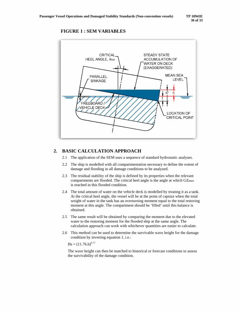
1.4 The total depth of the water on deck includes not only this elevation of the water surface, but also the depth of flooding on deck and the further sinkage of the ship due to the accumulation of water. These components are illustrated in Figure 1.
Passenger Vessel Operations and Damaged Stability Standards (Non-convention vessels) TP 10943E 30 of 33
FIGURE 1 : SEM VARIABLES
2. BASIC CALCULATION APPROACH 2.1 The application of the SEM uses a sequence of standard hydrostatic analyses.
2.2 The ship is modelled with all compartmentation necessary to define the extent of damage and flooding in all damage conditions to be analyzed.
2.3 The residual stability of the ship is defined by its properties when the relevant compartments are flooded. The critical heel angle is the angle at which GZmax is reached in this flooded condition.
2.4 The total amount of water on the vehicle deck is modelled by treating it as a tank. At the critical heel angle, the vessel will be at the point of capsize when the total weight of water in the tank has an overturning moment equal to the total restoring moment at this angle. The compartment should be ‘filled’ until this balance is obtained.
2.5 The same result will be obtained by comparing the moment due to the elevated water to the restoring moment for the flooded ship at the same angle. The calculation approach can work with whichever quantities are easier to calculate.
2.6 This method can be used to determine the survivable wave height for the damage condition by inverting equation 1, i.e.:
Hs = (11.76.h)0.77
The wave height can then be matched to historical or forecast conditions to assess the survivability of the damage condition.
Passenger Vessel Operations and Damaged Stability Standards (Non-convention vessels) TP 10943E 31 of 33
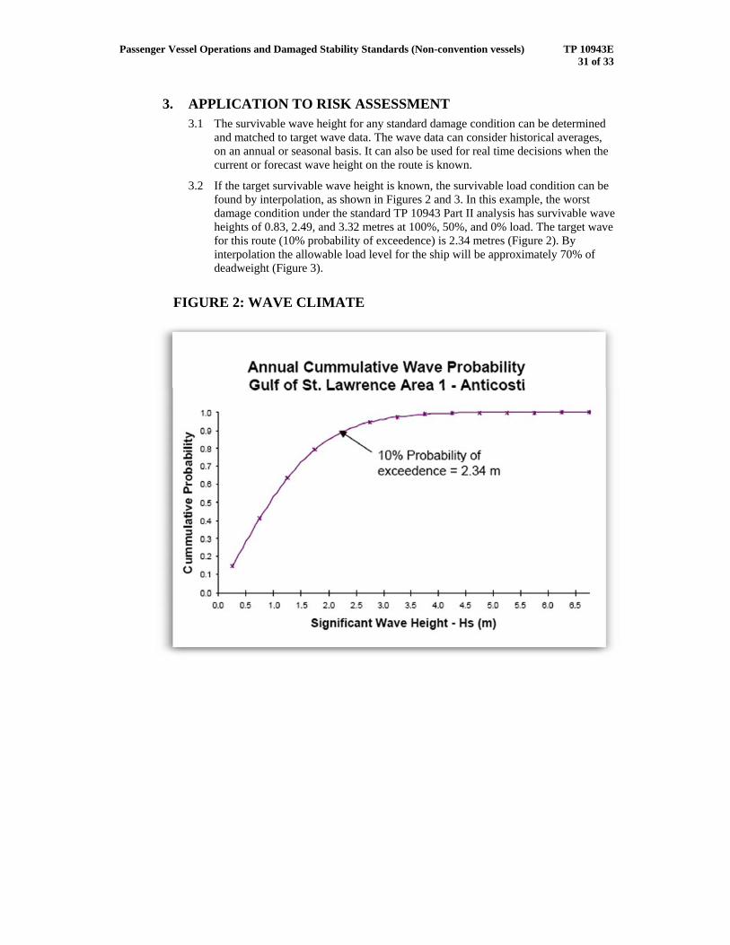
3. APPLICATION TO RISK ASSESSMENT 3.1 The survivable wave height for any standard damage condition can be determined
and matched to target wave data. The wave data can consider historical averages, on an annual or seasonal basis. It can also be used for real time decisions when the current or forecast wave height on the route is known.
3.2 If the target survivable wave height is known, the survivable load condition can be found by interpolation, as shown in Figures 2 and 3. In this example, the worst damage condition under the standard TP 10943 Part II analysis has survivable wave heights of 0.83, 2.49, and 3.32 metres at 100%, 50%, and 0% load. The target wave for this route (10% probability of exceedence) is 2.34 metres (Figure 2). By interpolation the allowable load level for the ship will be approximately 70% of deadweight (Figure 3).
FIGURE 2: WAVE CLIMATE

Passenger Vessel Operations and Damaged Stability Standards (Non-convention vessels) TP 10943E 32 of 33
FIGURE 3: CAPSIZE WAVE HEIGHT DERIVED FROM SEM FOR WORST CASE DAMAGE
3.3 For a Stage 3 approach it is necessary to develop a comprehensive list of single and twin compartment damage cases at full load, as per part II of the standard TP 10943
3.4 Test each damage case at full load for the degree of compliance (0 – 1) with the ‘s’ equation given in Circ 574 as follow:
4max58.2 AreaRangeGZcs ∗∗∗∗=
where:
GZmax is the maximum positive residual lever (m) within the range of 15° beyond the angle of equilibrium, but not more than 0.1 m;
Range is the range of positive righting levers beyond the angle of equilibrium, in degrees, but not more than 15°;
Area is the area under the righting lever curve (m-rad), measured from the angle of equilibrium to the lesser of the angles at which progressive flooding occurs, or 22° (measured from the upright) in the case of a one-compartment flooding, or 27° (measured from the upright) for the flooding of two or more compartments, but not more than 0.15 m-rad.

Passenger Vessel Operations and Damaged Stability Standards (Non-convention vessels) TP 10943E 33 of 33
In respect of the Area, please note that the allowable area is up to a heel angle, measured from the upright 22°/27°, depending on whether flooding of a single or two adjacent compartments is concerned.
and c is determined according to the following:
c = 1 where the final angle of equilibrium is not more than 7°;
c = 0 where the final angle of equilibrium is more than 20°;
else °−°
−°=
72020 ec θ
In all case where the margin line is immersed in the equilibrium condition, s is to be taken as 0.
3.5 Apply the SEM method to derive the survival wave height for each of the above damage cases at full load where the ‘s’ equation test result is < 1.
3.6 Apply the SEM method to derive the survival wave heights for each of the above damage cases at progressively reduced loads down to zero cargo.
3.7 Use the results of 5 and 6 to construct the operational envelope for the vessel covering the complete load range, as follows:
• For one-compartment designs, use the lowest survival wave heights for all single compartment damage cases at each load level.
• For two-compartment designs, use the lowest survival wave heights for all single and twin compartment damage cases at each load level.
3.8 When applying the SEM method to a damage case, the deck may be immersed in the equilibrium condition before the effect of the water accumulated on deck is taken into account provided that:
(a) the lower edge of openings through which progressive flooding may take place and such flooding is not accounted for in the calculation of factor s are not immerged. Such openings shall include air-pipes, ventilators and openings which are closed by means of weathertight doors or hatch covers; and
(b) no part of the bulkhead deck considered a horizontal evacuation route is immerged.
(c) the requirements of the standard TP 10943, part II subsection 8(2) are also met in the final stage of flooding.

Passenger Vessel Operations and Damaged Stability Standards (Non-convention vessels) TP 10943E 34 of 33
3.9 The Stage 3 operational envelope derived deterministically is shown below.
References [1] “Flooding Protection of Ro-Ro Ferries, Phase III”, TP13216, March 1998.
[2] “Dynamic Stability Assessment of Damaged Passenger/Ro-Ro Ships and Proposal of Rational Stability Criteria”; Vassalos et.al., Marine Technology Oct.97.