Pascal 2033-2063 Series - Lesker...2033 - 2063 m3/h rotary vane pumps. SD, C1, C2 Pascal series The...
71
Operating instructions Operating instructions Translated from original version Translated from original versionBetriebB BetriebB Pascal 2033-2063 Series Rotary vane pumps EN EN
Transcript of Pascal 2033-2063 Series - Lesker...2033 - 2063 m3/h rotary vane pumps. SD, C1, C2 Pascal series The...

Operating instructionsOperating instructions
Tra
nsla
ted
from
orig
inal
ver
sion
Tra
nsla
ted
from
orig
inal
ver
sionB
etrie
bBB
etrie
bB
Pascal 2033-2063 SeriesRotary vane pumps
ENEN

EN – 1
Rotary vane pumps2033 - 2063 SD-C1-C2
Welcome
Dear customer,
You have just bought an adixen rotary vane pump.
We would like to thank you and are proud to count you among our customers.
This product is a result of experience acquired over many years by adixen Vacuum Products in the design of rotary vane pumps.
APPLICATIONS:
• RESEARCH AND DEVELOPMENT
• INDUSTRY: FOODSTUFFS (FREEZE-DRYING), PHARMACEUTICAS, ELECTRONIC TUBE MANUFACTURE, METALLURGY, DRYING SYSTEMS, REFRIGERATION SYSTEMS, CHEMICAL INDUSTRY, ETC.
• VARIOUS SEMICONDUCTOR PROCESSES
We suggest that you read this manual, particularly the chapter on installation and operation, before you start to use this pump so that you can obtain optimum levels of performance and complete satisfaction from this equipment.
EN
Intr
od
uct
ion
The performance and operational safety of this product are guaranteed provided it is used normally in the operating conditions defined in this manual.
It is the customer’s task to:- train operators to use the product if they do not speak the language the manual is written in,- ensure operators know the safe practices to apply when using the product.
EN – 2
Copyright/Intellectual property:The use of adixen products are subject to copyright and intellectual property rights in force in any jurisdiction. All rights reserved. including copying this document in whole or any part without prior written authorization from adixen Vacuum Products.Specifications and information are subject to change without notice by adixen Vacuum Products.
This product complies with the requirements of European Directives. listed in the Declaration of Conformity contained in page 56 of this manual.
Indicates a potentially hazardous situation which, if not avoided, could result in moderate or minor injury. It may also be used to alert against unsafe practices.
Indicates a potentially hazardous situation which, if not avoided, could result in property damage.
Indicates an imminently hazardous situation that, if not avoided, will result in death or severe injury (extreme situations).
Indicates a potentially hazardous situation which, if not avoided, could result in death or severe injury.
Before switching on the appliance, study the user’s manual and make sure you follow the safety instructions it gives. You can recognise these by the ‘Caution’, ‘Warning’ and ‘Danger’ symbols. Good practice tips and manufacturer’s recommendations are in a grey box.

EN – 3
Contents
IntroductionPresentation of the product range ......................................................... 42033 - 2063 m3/h rotary vane pumps - SD, C1, C2 Pascal series ........... 5Operating principle of the rotary vane pump ......................................... 6Oil - Noise limiter - Antisudback ............................................................ 8Technical characteristics ......................................................................... 11Pump dimensions .................................................................................. 13Accessories ............................................................................................ 14
Start-upSafety instructions concerning the installation and operation ................. 15Table of recommended oils .................................................................... 17Mechanical connections ......................................................................... 21Electrical connections ............................................................................. 24External motor protection, electrical protection ...................................... 27
OperationPreliminary precautions .......................................................................... 29Operating temperature .......................................................................... 29Before starting up the pump .................................................................. 30Start-up ................................................................................................. 30Cold start-up ......................................................................................... 30Operation of gas ballast ......................................................................... 31Purges for pumping condensable, corrosive and hazardous gases .......... 33Oxygen pumping ................................................................................... 35Recovery of oil (high pressure pumping and cycling) .............................. 36
MaintenanceSafety instructions for maintenance ....................................................... 37Troubleshooting and corrective actions .................................................. 38Maintenance frequency ......................................................................... 41Draining ................................................................................................. 42Flushing ................................................................................................. 42Change of oil type ................................................................................. 42Start-up after pump disassembly or oil change ...................................... 43Tools and consumable products ............................................................. 44Disassembling the pump ........................................................................ 46Cleaning components ............................................................................ 49Replacement of all shaft seals ................................................................ 50Reassembling the pump ......................................................................... 52
Declaration of contamination ............................................................ 54
Declaration of Conformity ................................................................. 56
NomenclatureSpare parts lists ....................................................................................N – 1
Translated from original version
MANUEL P/N: 105527EDITION : 04 - July 2012
Intr
od
uct
ion
Sta
rt-u
pO
pera
tio
nM
ain
ten
an
ceN
om
en
clatu
reEN
EN – 4
Presentation of the product range
A wide rangeSpecific solutions adapted to
various applications
SD series
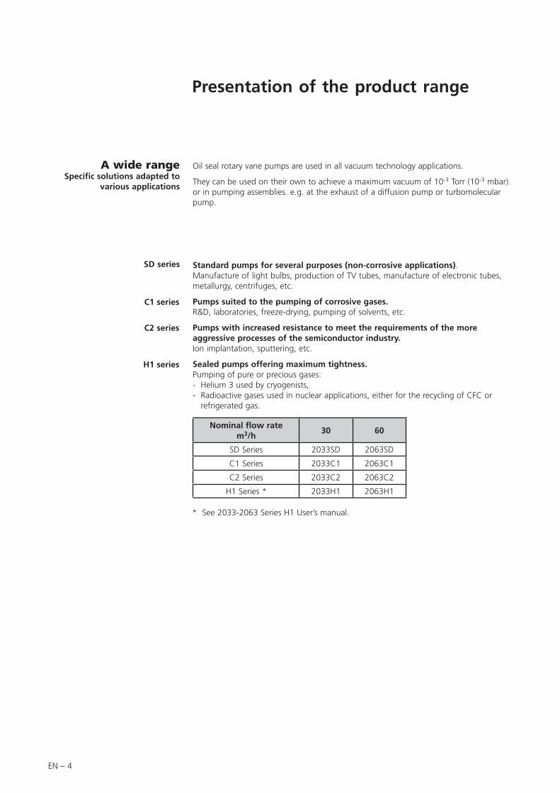
Oil seal rotary vane pumps are used in all vacuum technology applications.
They can be used on their own to achieve a maximum vacuum of 10-3 Torr (10-3 mbar). or in pumping assemblies. e.g. at the exhaust of a diffusion pump or turbomolecular pump.
Standard pumps for several purposes (non-corrosive applications).Manufacture of light bulbs, production of TV tubes, manufacture of electronic tubes, metallurgy, centrifuges, etc.
Pumps suited to the pumping of corrosive gases.R&D, laboratories, freeze-drying, pumping of solvents, etc.
Pumps with increased resistance to meet the requirements of the more aggressive processes of the semiconductor industry.Ion implantation, sputtering, etc.
Sealed pumps offering maximum tightness.Pumping of pure or precious gases:- Helium 3 used by cryogenists,- Radioactive gases used in nuclear applications, either for the recycling of CFC or
refrigerated gas.
Nominal flow ratem3/h
30 60
SD Series 2033SD 2063SD
C1 Series 2033C1 2063C1
C2 Series 2033C2 2063C2
H1 Series * 2033H1 2063H1
C1 series
C2 series
H1 series
* See 2033-2063 Series H1 User’s manual.

EN – 5
2033 - 2063 m3/h rotary vane pumps. SD, C1, C2 Pascal series
The 33 to 63m3/h pump models, have following main characteristics:
– A direct drive motor making them very compact.
– An anti-suckback system ensures the tightness of the pump during accidental or voluntary shutdowns.
– A gas ballast enables the pumping of condensable vapors.
– The universal three-phase motor can be disassembled independently of the rest of the pump, without the need to drain the oil case.
– On the oil case, a sight glass can be used to inspect the oil level easily when filling the oil case and during the operation of the pump.
– A neutral gas purge is used to degas oil and dilute pumped gases on C1 and C2 series models.
– An oil casing purge is used to dilute the pumped gases on C2 series models.
– Sensor connections for oil pressure or temperature sensors are available on C2 series models. The inlet and exhaust end fittings are PNEUROP ISO-KF standardized.
They can be used to connect many of our accessories (see page 14).
The main remplacement parts are interchangeable: This enables easier disassembly-assembly operations and replacement without changing the pump’s performance.
Various accessories can be used to adapt the pump to meet the requirements of your application.
1. Oil case2. Base3. Frame4. Electric motor5. Gas ballast control6. Spring hook (lifting device)7. Inlet end fitting8. Exhaust end fitting9. Oil case filling plug
10. Sensor connections (C2 Series)11. Oil level sight glass12. Oil draining plug13. Oil filter (C1 Series)
EN
Intr
od
uct
ion
9
13
10
8
11 12
84 7 6 5 9
122 1 113

EN – 6
Operating principle of the rotary vane pump
The pumping cycle isgiven below:
Inlet
Transfer
Compression
Exhaust
This is a volumetric pump, with a functional part composed of:• A hollow cylindrical stator with inlet and exhaust valves.• A rotor mounted eccentrically inside the stator for pumping.• Two vanes sliding in the rotor, forced against the stator by centrifugal force and
springs.
Single-stagerotary vane pump
As the vane passes in front of the inlet orifice, an increasing space is formed into which the gas from the chamber to be evacuated expands.When the second vane passes, the space is closed.
The gas trapped in the space between the two vanes is transferred to the exhaust orifice as the rotor rotates.
The space communicates with the exhaust. which is fitted with a valve: the gas is compressed until the safety valve is opened.
The gas is expelled into the oil casing when the pressure is sufficient to open the valve.
In. Exh.
In. Exh.
In. Exh.
In. Exh.

EN – 7
Two-stagerotary vane pump
To improve the backing pressure and flowrate at low pressure, two stages are connected in series. The second is similar to the first both structurally and operationally. The gases pulled in by the first stage (low pressure) are transferred to the second stage (high pressure) and discharged through the high pressure (HP) valve.
Applications Two stage rotary vane pumps are the best choice for application requiring an ultimate vacuum as low as 3.75.10-3 Torr (5 x 10⁻³ mbar).
Note: when operating a two stage vane pump continously, greater than half an hour - above 1.0 Torr,- or with opened gas ballast,the unit should be equipped with an oil mist eliminator equipped with an oil return system.
In.
Low pressure stage
Exh.
High pressure stage
EN
Intr
od
uct
ion
EN – 8
Oil - Noise limiter - Antisuckback
Oil has several important functions in the pump:– It lubricates mechanical components (bearings, seals, rotor, vanes, etc.).– It makes moving parts relatively tight by limiting internal leakage.– It carries away the heat produced by the compressed gases.
Oil
Choosing the right oil Not all oils produce the same ultimate pressure in a given pump. Ultimate pressure depends on the saturated vapor pressure of the oil, its viscosity and its ability to dissolve gases.
Good pumping conditions are related to the type of oil used. The choice depends on:– Expected pump performance.– Chemical aggression and corrosion of pumped gases.– Accessories used.– Desired maintenance intervals and total operating cost.
The manufacturer has selected various types of oil for its pumps (see page 17).
9 7
6
8
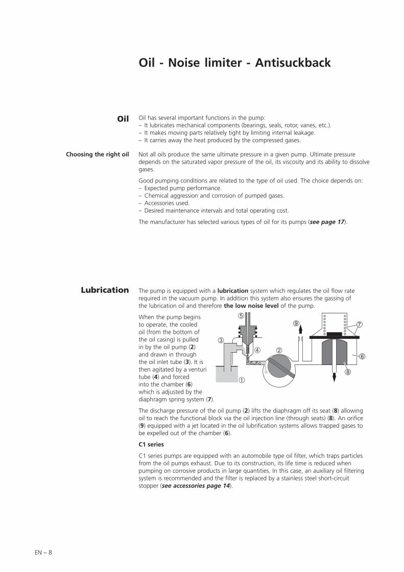
Lubrication The pump is equipped with a lubrication system which regulates the oil flow rate required in the vacuum pump. In addition this system also ensures the gassing of the lubrication oil and therefore the low noise level of the pump.
When the pump begins to operate, the cooled oil (from the bottom of the oil casing) is pulled in by the oil pump (2) and drawn in through the oil inlet tube (3). It is then agitated by a venturi tube (4) and forced into the chamber (6) which is adjusted by the diaphragm spring system (7).
The discharge pressure of the oil pump (2) lifts the diaphragm off its seat (8) allowing oil to reach the functional block via the oil injection line (through seats) (8). An orifice (9) equipped with a jet located in the oil lubrification systems allows trapped gases to be expelled out of the chamber (6).
C1 series
C1 series pumps are equipped with an automobile type oil filter, which traps particles from the oil pumps exhaust. Due to its construction, its life time is reduced when pumping on corrosive products in large quantities. In this case, an auxiliary oil filtering system is recommended and the filter is replaced by a stainless steel short-circuit stopper (see accessories page 14).
EN – 9
Parallel to the oil flow, there is a small orifice in the venturi tube (5), which reduces the noise level at ultimate pressure. Because of the negative pressure created at the end of the venturi tube (5), gases are entrained into the moving layers of oil dampening pump noise, allowing the fluid to become more compressible.The added gases will affect the ultimate pressure, therefore, a compromise between sound level and ultimate pressure has to be reached as follows:
- Tightening down air intake tube (5) decreases the oil flowrate at the intake of the oil pump (2) and increases the amount of gas mixture in the oil. The sound level decreases but the ultimate pressure increases.
- Unscrewing tube (5) increases the oil flowrate at the intake of the oil pump (2) and decreases the amount of air mixture with the oil. The sound level increases but the ultimate pressure decreases.
This adjustment can be performed via the oil fill port while the pump is in operation at ultimate pressure.
Anti-noise
Anti-suckback and tightness at
stopping
When the pump is stopped or the power is turned off, the anti-suckback device (6), (7) and (8) isolates the functional block of the pump against air or oil returning to the chamber being evacuated.
When the pump stops, the discharge pressure of the oil pump (2) drops rapidly through the jet (9). Diaphragm (7) under pressure from spring and the difference of pressure is forced againts its seat (8) thus closing off the injection line through the seat (8).
The seal is also ensured by flush-mounted o-rings between the faces of the functional parts (stators, flanges, housing...) and by spring loaded check valves in the discharge ports.
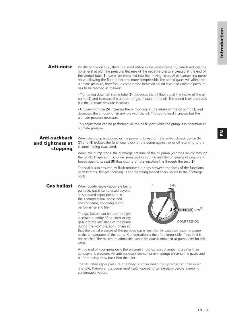
Gas ballast When condensable vapors are being pumped, gas is compressed beyond its saturated vapor pressure in the «compression» phase and can condense, impairing pump performance and life.
The gas ballast can be used to inject a certain quantity of air (inert or dry gas) into the last stage of the pump during the «compression» phase so that the partial pressure of the pumped gas is less than its saturated vapor pressure at the temperature of the pump. Condensation is therefore impossible if this limit is not reached.The maximum admissible vapor pressure is obtained at pump inlet for this value.
At the end of «compression», the pressure in the exhaust chamber is greater than atmospheric pressure. An anti-suckback device (valve + spring) prevents the gases and oil from being draw back into the inlet.
The saturated vapor pressure of a body is higher when the system is hot than when it is cold; therefore, the pump must reach operating temperature before pumping condensable vapors.
In.
COMPRESSION
air
Exh.
EN
Intr
od
uct
ion

EN – 10
Gas ballast (cont’d)
Using the gas ballast increases the ultimate pressure of the pump as well as the temperature.
The gas ballast control, located on the frame cannot be used to set the gas injection flow rate.
When the gas ballast control is open, the pump is not tight when stopped. To guarantee this tightness, install an automatic gas ballast.
The functioning in permanent regime with opened gas ballast draws away important oil losses (mist) by exhaust: use an accessory OME 40 HP + ODK (see page 14) or control the oil level very often.
C1 and C2 pump series:Because of the danger present if the gas ballast (C1 series) or purge gas ballast (C2 series) was to be opened to atmosphere, remove the plug and connect the port to a neutral gas supply line (see page 31).

EN – 11
(1) Partial ultimate pressure and vapor pressure measured according to Pneurop 6602 specifications with A120 oil charge. It may vary if other oils are used (see page 17).(2) These values are for pumps equipped with IE2 European three-phase motors.
Note: The pressure measurements were made with a capacitive diaphragm pressure gauge measuring a total pressure in the absence of a cold trap. Measurements using a Pirani type gauge can give different pressure values.
(3) Vapor pressure measured with an automatic gas ballast.
Characteristics Unit 2033 SD 2063 SD
Frequency HZ 50 60 50 60
Number of stages 2 2
Nominal rotation speed rpm 1500 1800 1500 1800
Nominal flow ratem3/h
cfm
30
23.3
60
42.4
Flow rate Pneurop methodm3/h
cfm
2718.8
5538
Partial ultimate pressure (1) with A120 oilTorr/mbar
Pa
3.75.10-4 / < 5.10-4
5.10-2
3.75.10-4 / < 5.10-4
5 .10-2
Ultimate pressure with gas ballast closed Torr/mba/Pa 2.25.10-3 / 3.10-3 / 3.10-1
Ultimate pressure with gas ballast open (3) Torr/mbar/Pa 1.5.10-2 / 2.10-2 / 2
Maximum pressure in continuous operation
• without oil recovery
• with oil recoveryTorr/mbar/Pa
7.5 / < 10 / 1.103
75 / > 100 / 1.104
Maximum exhaust relative overpressure bar 0.5
Oil capacity (case) l 3.6 7
Maximum water vapor pumping capacity (3) (1) Torr/mbar
Pa
303.103
2525.102
Water vapor pumping capacity g/h 700 1200
Weight (pump + motor) (2) kg (lb) 65.5 (144.4) 102 (224.9)
Inlet and exhaust end fittings DN 40 ISO-KF
Ambient operating temperature °C min 12 / max 45
Ambient storage temperature °C min 5 / max 65
For industry: SD Series
Characteristics Unit 2033 C1 2063 C1
Frequency HZ 50 60 50 60
Number of stages 2 2
Nominal rotation speed rpm 1500 1800 1500 1800
Nominal flow ratem3/h CFM 30
23.3
60
42.4
Flow rate Pneurop methodm3/h CFM 27
18.8
5538
Partial ultimate pressure (1) with A120 oil Torr/mbar/Pa 3.75.10-4 / 5.10-4 / 5.10-2
Ultimate pressure with gas ballast closed Torr/mbar/Pa 2.25.10-3 / 3.10-3 / 3.10-1
Ultimate pressure with gas ballast open (3) Torr/mbar/Pa 1.5.10-2 / 2.10-2 / 2
Maximum pressure in continuous operation
• without oil recovery
• with oil recoveryTorr/mbar/Pa
7.5 / < 10 / 1.103
75 / > 100 / 1.104
Maximum exhaust relative overpressure bar 0.5
Oil capacity l 3.6 7
Maximum water vapor pumping capacity (3) (1) Torr/mbar
Pa
303.103
2525.102
Water vapor pumping capacity g/h 700 1200
Weight (pump + motor) (2) kg (lb) 68.5(150) 105.5 (232.6)
Inlet and exhaust end fittings DN 40 ISO-KF
Ambient operating temperature °C min 12 / max 45
Ambient storage temperature °C min 5 / max 65
Corrosive applications: C1 Series
Technical characteristics
EN
Intr
od
uct
ion
EN – 12
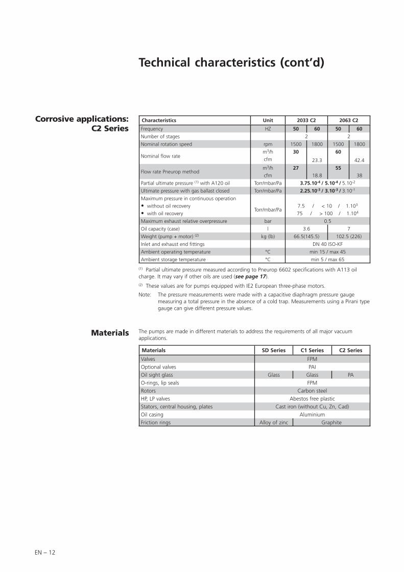
Technical characteristics (cont’d)
Characteristics Unit 2033 C2 2063 C2
Frequency HZ 50 60 50 60
Number of stages 2 2
Nominal rotation speed rpm 1500 1800 1500 1800
Nominal flow ratem3/h
cfm
30
23.3
60
42.4
Flow rate Pneurop methodm3/h
cfm
2718.8
5538
Partial ultimate pressure (1) with A120 oil Torr/mbar/Pa 3.75.10-4 / 5.10-4 / 5.10-2
Ultimate pressure with gas ballast closed Torr/mbar/Pa 2.25.10-3 / 3.10-3 / 3.10-1
Maximum pressure in continuous operation
• without oil recovery
• with oil recoveryTorr/mbar/Pa
7.5 / < 10 / 1.103
75 / > 100 / 1.104
Maximum exhaust relative overpressure bar 0.5
Oil capacity (case) l 3.6 7
Weight (pump + motor) (2) kg (lb) 66.5(145.5) 102.5 (226)
Inlet and exhaust end fittings DN 40 ISO-KF
Ambient operating temperature °C min 15 / max 45
Ambient storage temperature °C min 5 / max 65
Corrosive applications: C2 Series
(1) Partial ultimate pressure measured according to Pneurop 6602 specifications with A113 oil charge. It may vary if other oils are used (see page 17).(2) These values are for pumps equipped with IE2 European three-phase motors.
Note: The pressure measurements were made with a capacitive diaphragm pressure gauge measuring a total pressure in the absence of a cold trap. Measurements using a Pirani type gauge can give different pressure values.
Materials
Materials SD Series C1 Series C2 Series
Valves FPM
Optional valves PAI
Oil sight glass Glass Glass PA
O-rings, lip seals FPM
Rotors Carbon steel
HP, LP valves Abestos free plastic
Stators, central housing, plates Cast iron (without Cu, Zn, Cad)
Oil casing Aluminium
Friction rings Alloy of zinc Graphite
The pumps are made in different materials to address the requirements of all major vacuum applications.

EN – 13
Pump dimensions
U
353
13.7
402
15.6
T
389 to 398
15 to 5.5
438 to 447
17 to 17.4
S
452
17.6
526
20.5
R
91
3.5
91
3.5
Q
213
8.3
264
10.2
P
140
5.4
190
7.4
O
12
0.46
12
0.46
N
362 to 385
14.1 to 15
410 to 422
16 to 6.4
M
323
12.5
371
14.4
L
164
6.3
186
7.2
K
336
13.1
385
15
J
42
1.6
45
1.7
H
53
2
56
2.1
G
437
17
521
20.3
F
375
14.6
459
17.9
E
206
8
229
8.9
D
31
1.2
29
1.13
C
103
4
118
4.6
B
288
11.2
342
13.3
A
455
17.7
52920.6
2033
2063
SD Series
C2 Series
C1 Series
Dimensions en mm (inch)
EN
Intr
od
uct
ion
2033 motors
P/N
Dimensions(mm/inch) Weight
(kg/lb)l d h a
114449 27010.6
1706.7
1405.5
2007.9
21.747.8
119997 26710.5
1777
1375.4
1435.6
18.240.1
119998 26710.5
1777
1375.4
1435.6
16.436.2
2063 motors
P/N
Dimensions(mm/inch) Weight
(kg/lb)l d h a
114450 30011.8
1907.5
1505.9
2309.1
29.865.7
119979 32112.6
1967.7
1445.7
1495.9
2657.3
119980 32112.6
1967.7
1445.7
1495.9
2657.3

EN – 14
Accessories
Name SD C1 C2 Part number Location Fonctions
Oil mist
eliminator
OME 40 S 104887
Exhaust• Separates oil droplets and particles contained in exhaust gases emitted by the pump.
OME 40 C1 068785
OME 40 C2 068492
High pressure oil mist eliminator
OME 40 HP+200024 Exhaust
• Separates oil droplets and particles contained in exhaust gases emitted by the pump when pump operate in high pressure and/or in frequent cycles.
Can be fitted to ODK 136 and ODK 236.
Oil level switch
OLS 36104377 On oil casing
Provide information about oil level inside oil casing of RVP, whenever the pump is located in an unaccessible area.
Oil draining kit
ODK 136118773 Gas ballast
• Connect to the OME 40 HP+, it is used to recover oil via the gas ballast.Note : the pump is not sealed when switched off.
Oil draining kit
ODK 236
118776: 220/240V 50/60 Hz
118777: 115V 60 HZInlet
Connect to the OME 40 HP+, it is used to recover oil. Equipped with an electrovalve which seals the pump when switched off.
Sorption trap
ST 40 104731 -115V053380 220 V
Inlet • Prevents oil backstreaming when pumping in a “clean” vacuum.
Automatic gas ballastAGB 36
068391: 230V 50/60Hz104367 115V 60Hz
Gas ballast
• Remote control for gas ballast.
• Allows the gas ballast to be closed when the pump is off, ensuring that the pump is tight.
Oil filter
DE1068990 220V 50/60Hz068991 115V 50/60Hz
External device• Filters and/or neutralizes oil when pumping gases which are corrosive and could rapidly degrade oil quality.Oil filter
DE2104374 220V 50/60Hz104375 115V 50/60Hz
Shock mount082691
LAX 100 model D
Between base and machine
frame• Allows pump to be mounted on a frame.
Oil short-circuit adaptor
054273On the wessel
pipe fitting
• On C1 model, allows to remove the oil filter cartridge and replace it by an oil filtration system type DE1 or DE2.
Possible without restrictions Possible with restrictions Out of question
When pumping on corrosive, aggressives or flammable gases, the gas can cause injury or death. In these cases,- connect the exhaust of the pump to an exhaust stack or an evacuation
duct.- connect a relief valve or rupture disc directly on the pump. Contact your
closest service center (see addresses at the back of the manual). When the exhaust is connected to an extraction duct or an oil mist
eliminator, you must remove the exhaust safety valve mounted in the pump’s exhaust orifice. At the pump exhaust, the discharge circuit must be such that the resulting excess pressure in the oil case is as low as possible. The maximum excess pressure recommended for correct pump operation is 0.5 bar (6 PSI).A slight negative pressure in the oil case (0.1 to 0.2 bar / 1.5 PSI), at the exhaust, will prevent gases from accumulating and reduce pump corrosion and pollution. For safety reasons, use accessories on the inlet and exhaust lines whose materials and sealing properties are compatible with the gases being used.
EN – 15
EN
Sta
rt-u
p
Safety instructions concerning the installation and operation
Storage
Unpacking
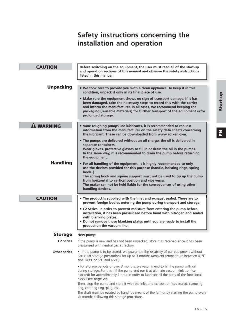
Before switching on the equipment, the user must read all of the start-up and operation sections of this manual and observe the safety instructions listed in this manual.
C2 series
Other series
The product is supplied with the inlet and exhaust sealed. These are to prevent foreign bodies entering the pump during transport and storage.
C2 Series: In order to prevent moisture from entering the pump before installation, it has been pressurized before hand with nitrogen and sealed with blanking plates. Do not remove these blanking plates until you are ready to install the product on the vacuum line.
New pump:
If the pump is new and has not been unpacked, store it as received since it has been pressurized with neutral gas at factory.
• If the pump is to be stored, we guarantee the reliability of our equipment without particular storage precautions for up to 3 months (ambient temperature between 41°F and 149°F or 5°C and 65°C).
• For storage periods of over 3 months, we recommend to fill the pump with oil during storage. For this, fill the pump and run it at ultimate vacuum (inlet orifice blocked) for approximately 1 hour in order to lubricate all the parts of the functional block (see page 29).Then, stop the pump and store it with the inlet and exhaust orifices sealed: clamping ring, centring ring, plug, etc.The shaft must be rotated by hand (be means of the fan) or by starting the pump every six months following this storage procedure.
We took care to provide you with a clean appliance. To keep it in this condition, unpack it only in its final place of use.
Make sure the equipment shows no sign of transport damage. If it has been damaged, take the necessary steps to record this with the carrier and inform the manufacturer. In all cases, we recommend keeping the packaging (reusable materials) for further transport of the equipment orfor prolonged storage.
Vane roughing pumps use lubricants, it is recommended to request information from the manufacturer on the safety data sheets concerning the lubricant. These can be downloaded from www.adixen.com.
The pumps are delivered without an oil charge: the oil is delivered in separate containers. Wear gloves, protective glasses to fill in or drain the oil in the pumps.In the same way, it is recommended to drain the pump before returning the equipment.
For all handling of the equipment, it is highly recommended to only use the devices provided for this purpose (handle, hoisting rings, spring hook..).The spring hook and square support must not be used to tip up the pump from horizontal to vertical position and vice versa.The maker can not be held liable for the consequences of using other handling devices.
Handling

EN – 16
Installation andstart-up
All series
• After 3 months storage without oil, factors such as temperature, degree of humidity, salt air, etc. may cause the deterioration of the pump components, particularly the hardening of O-rings and the "sticking" of lip seals on shafts and the gumming of oil. In this state, a pump may have operational problems, particularly oil leaks. Before any start-up (new pump as well as used), the pump must be disassembled (see page 46), and all the seals changed.
Pump which have been used:If the pump is not new, drain and rinse it (see page 42). Fill it with new oil, then pump a dry inert gas through it to remove all traces of dampness in the pumping system and oil casing. Pump in dry inert gas as fallows:- 10 minutes at above 2.25 Torr (30 mbar).- 10 minutes at ultimate pressure with gas ballast open.- 10 minutes at ultimate pressure.Stop the pump and seal the inlet and exhaust orifices tightly with quick connect clamps, centering rings, blank-off flanges...
Note:The seal kits must be stored with caution. Keep them away from heat and light (sunlight and ultraviolet light) in order to prevent the elostomers from hardening (AFNOR standard FD T 46.022).
Storage (cont’d)
The pump must be operated in the horizontal position with the pumping axis vertical and the inlet operating upwards.
Ensure that the product is connected to an electrical installation:- in compliance with the local and national safety requirements,- equipped with electrical protection (fuses, circuit breaker, …) which has a suitable earth (ground) point, properly connected.
Do not expose any part of the human body to vacuum. The product is supplied with the inlet and exhaust sealed. Remove these blanking plates when you are ready to connect the product on your vacuum system.As well as, don’t operate the product unless the inlet and exhaust are connected to a vacuum and exhaust pumping line.
The products are designed to avoid subjecting users to heat hazards. Specific operating conditions can nevertheless exist that require extra caution from users due to the high temperatures generated (outer surfaces > 70° C):Wear protective gloves to work on the appliance, especially during maintenance.
Our pumps are tested in the factory with A120 oil or A119 for the USA (A113 oil for the C2 series).
It is recommended to use the same oil during operation, because the oils are not mixable (refer to table page 17 and remplacement fluids page 18).
• If changing the type of oil, refer to the chapter concerned for the procedure and the type of lubricant required (see page 42).
EN – 17
EN
Sta
rt-u
p
Table of recommended oils
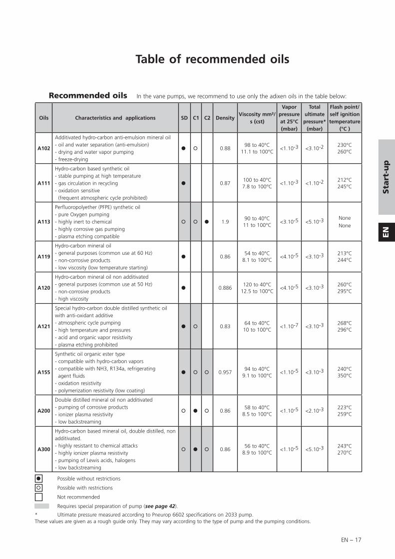
Oils Characteristics and applications SD C1 C2 DensityViscosity mm²/
s (cst)
Vapor pressure at 25°C (mbar)
Total ultimate
pressure* (mbar)
Flash point/self ignition temperature
(°C )
A102
Additivated hydro-carbon anti-emulsion mineral oil - oil and water separation (anti-emulsion)- drying and water vapor pumping- freeze-drying
0.8898 to 40°C
11.1 to 100°C<1.10-3 <3.10-2 230°C
260°C
A111
Hydro-carbon based synthetic oil - stable pumping at high temperature- gas circulation in recycling - oxidation sensitive (frequent atmospheric cycle prohibited)
0.87100 to 40°C7.8 to 100°C
<1.10-3 <1.10-2 212°C245°C
A113
Perfluoropolyether (PFPE) synthetic oil- pure Oxygen pumping- highly inert to chemical- highly corrosive gas pumping- plasma etching compatible
1.990 to 40°C11 to 100°C
<3.10-5 <5.10-3 NoneNone
A119
Hydro-carbon mineral oil - general purposes (common use at 60 Hz)- non-corrosive products- low viscosity (low temperature starting)
0.8654 to 40°C
8.1 to 100°C<4.10-5 <3.10-3 213°C
244°C
A120
Hydro-carbon mineral oil non additivated- general purposes (common use at 50 Hz)- non-corrosive products- high viscosity
0.886120 to 40°C
12.5 to 100°C<4.10-5 <3.10-3 260°C
295°C
A121
Special hydro-carbon double distilled synthetic oil with anti-oxidant additive- atmospheric cycle pumping- high temperature and pressures- acid and organic vapor resistivity- plasma etching prohibited
0.8364 to 40°C10 to 100°C
<1.10-7 <3.10-3 268°C296°C
A155
Synthetic oil organic ester type - compatible with hydro-carbon vapors- compatible with NH3, R134a, refrigerating agent fluids- oxidation resistivity- polymerization resistivity (low coating)
0.95794 to 40°C
9.1 to 100°C<1.10-5 <3.10-3 240°C
350°C
A200
Double distilled mineral oil non additivated- pumping of corrosive products- ionizer plasma resistivity- low backstreaming
0.8658 to 40°C
8.5 to 100°C<1.10-5 <2.10-3 223°C
259°C
A300
Hydro-carbon based mineral oil, double distilled, non additivated.- highly resistant to chemical attacks- highly ionizer plasma resistivity- pumping of Lewis acids, halogens - low backstreaming
0.8656 to 40°C
8.9 to 100°C<1.10-5 <5.10-3 243°C
270°C
Recommended oils In the vane pumps, we recommend to use only the adixen oils in the table below:
Possible without restrictions
Possible with restrictions
Not recommended
Requires special preparation of pump (see page 42).
* Ultimate pressure measured according to Pneurop 6602 specifications on 2033 pump.These values are given as a rough guide only. They may vary according to the type of pump and the pumping conditions.

EN – 18
ATP
2033 and 2063 m3/h SD, C1 series pumps are tested in the factory with A120 oil (A119 for the US).
2033 and 2063 m3/h C2 series pumps are tested in the factory with A113 oil.
At delivery, there is some oil remaining in the functional block.
Filling with oil
Mineral oil:ELF MOVIXA PV 100, TURBELF SA 100,BP CS 100 (BP registered trademark)SHELL VITREA 100 (SHELL registered trademark)TOTAL CORTIS PV 100 (TOTAL registered trademark)INLAND 19, INLAND 20 (INLAND registered trademark)MR 200 (MATSUMURA registered trademark)
Mineral-based synthetic oils:ELF BARELF F 100, ELF BARELF C 68 (ELF registered trademark)INVOIL 20 (INLAND registered trademark)INLAND TW (INLAND registered trademark)ELITE Z (CAMBRIGE MILL PRODUCTS, INC. reg. trademark)
Ester type synthetic oils:ANDEROL 555 (ANDEROL-BV registered trademark)ANDEROL RCF 96 N (ANDEROL-BV registered trademark)
Fluorocarbon synthetic oils:FOMBLIN YL VAC 25-6 (MONTEDISON registered trademark)KRYTOX 15-25 (DU PONT DE NEMOURS registered trademark)HALOVAC 100 (HALOCARBON registered trademark)AFLUNOX 15.25 (SCM registered trademark)
Note: In this case, pump performances may be slightly different from those given in pages 11 and 12.
However, the following replacement fluids can be used:
Our pumps are tested in the factory with adixen’s oil: it is recommended to use the same oil during operation. To change the type of oil, refer to the Maintenance Chapter, “replacement of oil type” section.In all cases, follow the recommendations of the pump specifier for the choice of oil to be used.
The pumps are delivered without an oil charge: the oil is delivered in separate containers. Wear a mask, gloves, protective glasses to fill in or drain the oil in the pumps.In the same way, it is recommended to drain the pump before returning the equipment.
Recommended oils (cont’d)

EN – 19
A
B
EN
Sta
rt-u
p
Checking the oil level To use the pump in optimum conditions, the oil level must be observed and checked regularly. This level is checked with the pump switched off, hot and on a horizontal plane.
Note: Optimum pump performance and service life are obtained when the oil level is between the maximum level and the minimum level.
Oil levelsight glassC1 Series
maximum level
minimum level
Oil levelsight glass
SD and C2 Series
maximum level
If necessary, carry out the special preparation procedure for the pump (see page 41), then:- remove the filling cap (A).- fill with oil until: - the oil is between the maximum and
minimum levels (SD, C2 Series), - the oil reaches the middle of the sight
glass (C1 Series).
This operation must be performed with the pump switched off.
At the first start-up, to facilitate lubrication of the pump, pour a few drops of oil (1 to 2 cm3) through the inlet orifice.
C2 series: if the pump is equipped with an oil temperature sensor, the installation must be made with the pump drained of oil.

EN – 20

EN – 21
EN
Sta
rt-u
p
Mechanical connections
The pump can be mounted on a frame using the 4 attachment holes on the base and the special shock mounts (refer to accessories page 14).
Note: Special shock mounts, effective against the pump's own vibrations, can also be used but they do not ensure correct attachment during the transfer of equipment. In this case, the pump should be clamped onto its support (see page 13).
Mounting on a frame
Ventilation
For a given application, pump performance, vacuum characteristics, temperature and reliability depend on the following:• assembly conditions (accessory, filter...) and mechanical connections,• used oil,• maintenance frequency and quality.For the assembly of the vacuum circuit, provide the accessories required for maintenance: isolation valves, purges, etc. For safety reasons, use accessories on the inlet and exhaust lines whose materials and sealing properties are compatible with the gases being used.Several fitting accessories are available in the adixen products’ catalog.
The pump and the motor are each equipped with a ventilation system.During pump installation, the pump should be placed in ventilated place. Provide a minimum gap of 25 mm around the pump.The vents on the pump and the motor should be checked regularly to ensure that they are not blocked.adixen pumps are designed for operation at an ambient temperature between 53°F and 113°F (12 and 45°C) (with A120 oil).
Inlet and exhaust fitting
Do not expose any part of the human body to vacuum. The product is supplied with the inlet and exhaust sealed. Remove these blanking plates when you are ready to connect the product on your vacuum system.As well as, don’t operate the product unless the inlet and exhaust are connected to a vacuum and exhaust pumping line.
At inlet:
Make sure that the parts or chambers connected to the inlet of ourpumps products withstand a negative pressure of 1 bar in relation to the atmospheric pressure.
The inlet pressure must be no higher than atmospheric pressure.Too high pressure can damage the product.

EN – 22
The pump inlet and exhaust orifices are equipped with DN 40 ISO-KF end fittings which can be used to fit various line components made of stainless steel, plastic, etc. (see the adixen catalog).
Inlet and exhaust fitting
(cont’d)
At exhaust: When pumping on corrosive, aggressives or flammable gases, the gas can cause injury or death. In these cases,- connect the exhaust of the pump to an exhaust stack or an evacuation
duct.- connect a relief valve or rupture disc directly on the pump. Contact your
closest service center (see addresses at the back of the manual). When the exhaust is connected to an extraction duct or an oil mist
eliminator, you must remove the exhaust safety valve mounted in the pump’s exhaust orifice.
Make sure the exhaust pressure does not exceed 1500 mbar (absolute). Too high a pressure can damage the appliance.Check periodically that the pipes and accessories connected at exhaust are not clogged and that the purge is running (Series C1, C2).
After connecting the appliance to the pump ing line, check for leaks along the whole of the line to ensure proper connections have been made (pump, pipes, valves, etc.).
ExhaustInlet

EN – 23
EN
Sta
rt-u
p
Purge and indicator connections
Serie Item Description Connection
C2
C1
1 Gas ballast purge 1/8’ NPT
2 Oil casing purge 1/8’ NPT
3 Oil pressure sensor connection *
M 10 X 1
4 Purge - Bubbler 1/8’ NPT
5Oil casing temperaturesensor connection *
M 12 X 1
Specific equipment: HP valve(C2 Series)
The C2 pumps are equipped with HP and LP elastomer valves (FPM™ according to standard NFT 40-002). In certain applications with fluorinated gases, HP valve may harden and become brittle and compromise pump performances. Alternatively, the pump may be equipped with a plastic, corrosion-resistant HP valve on request. On request we can supply these specific components depending on your needs.
Equipment HP Valve material Tightness Part Number
Standard Elastomer Installation tight 053443
On requestPlastic * Installation not tight 065057
Plastic + special o–ring Installation tight 065160
* If a plastic valve is used, the pump’s anti-suckback operation cannot be guaranteed and an anti-suckback device must be installed in the pumping line to ensure tightness when the pump is not operating.
* Sensors are customer supplied.
C2 Series C1 series
EN – 24
Electrical connections
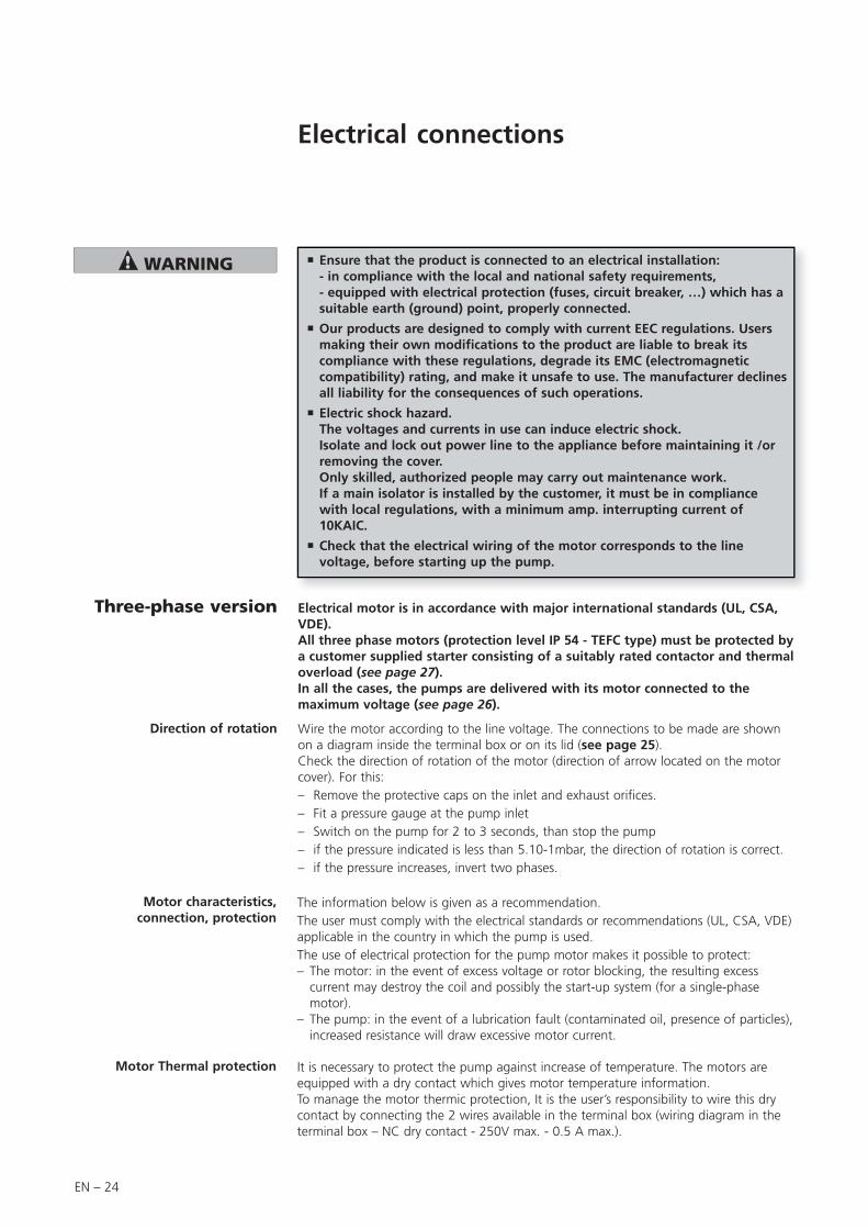
Electrical motor is in accordance with major international standards (UL, CSA, VDE).All three phase motors (protection level IP 54 - TEFC type) must be protected by a customer supplied starter consisting of a suitably rated contactor and thermal overload (see page 27).In all the cases, the pumps are delivered with its motor connected to the maximum voltage (see page 26).
Wire the motor according to the line voltage. The connections to be made are shown on a diagram inside the terminal box or on its lid (see page 25).Check the direction of rotation of the motor (direction of arrow located on the motor cover). For this:– Remove the protective caps on the inlet and exhaust orifices.– Fit a pressure gauge at the pump inlet– Switch on the pump for 2 to 3 seconds, than stop the pump– if the pressure indicated is less than 5.10-1mbar, the direction of rotation is correct.– if the pressure increases, invert two phases.
Three-phase version
Ensure that the product is connected to an electrical installation:- in compliance with the local and national safety requirements,- equipped with electrical protection (fuses, circuit breaker, …) which has a suitable earth (ground) point, properly connected.
Our products are designed to comply with current EEC regulations. Users making their own modifications to the product are liable to break its compliance with these regulations, degrade its EMC (electromagnetic compatibility) rating, and make it unsafe to use. The manufacturer declines all liability for the consequences of such operations.
Electric shock hazard.The voltages and currents in use can induce electric shock. Isolate and lock out power line to the appliance before maintaining it /or removing the cover. Only skilled, authorized people may carry out maintenance work.If a main isolator is installed by the customer, it must be in compliance with local regulations, with a minimum amp. interrupting current of 10KAIC.
Check that the electrical wiring of the motor corresponds to the line voltage, before starting up the pump.
Motor characteristics, connection, protection
The information below is given as a recommendation.The user must comply with the electrical standards or recommendations (UL, CSA, VDE) applicable in the country in which the pump is used.The use of electrical protection for the pump motor makes it possible to protect:– The motor: in the event of excess voltage or rotor blocking, the resulting excess
current may destroy the coil and possibly the start-up system (for a single-phase motor).
– The pump: in the event of a lubrication fault (contaminated oil, presence of particles), increased resistance will draw excessive motor current.
Direction of rotation
Motor Thermal protection It is necessary to protect the pump against increase of temperature. The motors are equipped with a dry contact which gives motor temperature information.To manage the motor thermic protection, It is the user’s responsibility to wire this dry contact by connecting the 2 wires available in the terminal box (wiring diagram in the terminal box – NC dry contact - 250V max. - 0.5 A max.).

EN – 25
EN
Sta
rt-u
p
Differential circuit breaker.In case of insulation defect, for personnel protection you must install on the main power supply a type B differential circuit breaker GFI (or RCD) of 30 mA minimum.This equipment protection device is compatible with type T.T electrical network.For other network type T.N or I.T, apply the right protection device. Contact adixen product manufacturer for advice.In all cases, comply with current local regulations.
Terminal box with 9 wires and 6 terminals
The pumps are equipped with 6 or 9 wire terminal box motors, the wiring diagram of the terminals is given as a rough guide only. In the event of doubt, only the plate in the terminal box should be used as a reference.
Electrical connections of three-phase
motors
Terminal box with 6 wires and 6 terminals
EN – 26
Electrical connections of three-phase
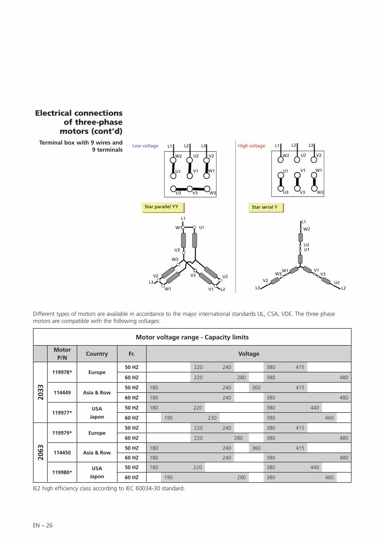
motors (cont’d)Terminal box with 9 wires and
9 terminals
Different types of motors are available in accordance to the major international standards UL, CSA, VDE. The three phase motors are compatible with the following voltages:
Motor voltage range - Capacity limits
Motor P/N
Country Fr. Voltage
2033
119978* Europe50 HZ 220 240 380 415
60 HZ 220 280 380 480
114449 Asia & Row50 HZ 180 240 360 415
60 HZ 180 240 380 480
119977*USA
Japon
50 HZ 180 220 380 440
60 HZ 190 230 380 460
2063
119979* Europe50 HZ 220 240 380 415
60 HZ 220 280 380 480
114450 Asia & Row50 HZ 180 240 360 415
60 HZ 180 240 380 480
119980*USA
Japon
50 HZ 180 220 380 440
60 HZ 190 280 380 460
IE2 high efficiency class according to IEC 60034-30 standard.

EN – 27
EN
Sta
rt-u
p
External motor protection, electrical protection
Circuit breaker rate for the following motors
Motor P/N Country Frequency Motor power Voltage Rate
2033
119978 Europe50 / 60 HZ 1,1 kW
220 V
400 V
6 A
4 A
60 HZ 1,3 kW265 V
460 V
6 A
4 A
114449 Asia & Row50 HZ 1,5 kW
200 V
400 V
8 A
4 A
60 HZ 1,8 kW230 V
460 V
8 A
4 A
119977USA
Japon
50 HZ 1,5 kW200 V
400 V
8 A
4 A
60 HZ 1,8 kW230 V
460 V
8 A
4 A
2063
119979 Europe50 HZ 2,2 kW
230 V
400 V
10 A
6 A
60 HZ 2,64 kW265 V
460 V
12 A
6 A
114450 Asia & Row50 HZ 2,2 kW
200 V
400 V
8 A
4 A
60 HZ 2 ,2 kW230 V
460 V
8 A
4 A
119980USA
Japon
50 HZ 2,2 kW200 V
400 V
14 A
6 A
60 HZ 2,64 kW230 V
460 V
12 A
6 A
The characteristics and ratings of fuses and recommended circuit breaker with standard pump three-phase motors:
Electrical protections
Installation protection with circuit breaker.The user must supply the pump from facilities equipped with amain circuit breaker, curve D (IEC 60947-2), in accordance with local regulations and with a minimum amp. interrupting current of 10 KAIC.This protection device should be in close proximity to the pump (no further than 7m (25 ft) within line of sight of the pump).

EN – 28

EN – 29
EN
Op
era
tio
n
Operation
Preliminary precautions
At start-up, before switching on the motor, check that the oil bath temperature is greater than 53°F (12°C).
The ambient operating temperature for the pump must be between 53°F (12°C) and 113°F (45°C).
Under these conditions, the stabilized pump temperature (at the front of the oil case) will be between 140°F and 158°F (60 and 70°C) (with A120 oil, depending on operating conditions).
Special case - Synthetic oils
Synthetic oils are much more viscous when cold than mineral oils.
Do not start up the pump at ambient temperatures below 59°F (15°C).
The stabilized temperature is higher than with a pump used with mineral oil.
For the same reason and to facilitate lubrication of the pump, pour a few drops of oil (1 to 2 cm3) through the inlet orifice before starting.
Operatingtemperature
The performance and operational safety of this product are guaranteed provided it is used normally in the operating conditions defined in this manual. It is the customer’s task to: - train operators to use the product if they do not speak the language the manual is written in,- ensure operators know the safe practices to apply when using the product.
Fire protection. The roughing pump is not intented to be installed on process containing
flammable materials or in hazardous atmosphere.
Fire hazard due to the presence of electrical components. The fire hazard is low due to the use of appropriated components and the
containment in the pump cover.
The vacuum pump is also a compressor: incorrect use may be dangerous.Study the user’s manual before starting up the pump.
The products are designed to avoid subjecting users to heat hazards. Specific operating conditions can nevertheless exist that require extra caution from users due to the high temperatures generated (outer surfaces > 70° C):Wear protective gloves to work on the appliance, especially during maintenance.
The products are factory tested to ensure they will not leak in normal operating conditions. It is the user’s responsibility toensure this level of leak tightness is maintained.»
For emergencies and breakdowns, contact the manager of your local service center (see addresses at back of manual).

EN – 30
Start-up • When using a three phase motor, check the direction of rotation of the motor (see electrical connections page 24).
• Check the oil level (see page 20).
• Start-up the pump.
• Allow the pump to run for one hour with the inlet blocked at ultimate vacuum:During this operation, make sure that the oil circuit is operating. Remove one of the oil fill plugs to listen to the pump.
At start-up, the oil enters the lubrication circuit of the vacuum pump. As a result, noises will be heard (first irregularly, then regularly) which will reduce as the oil heats up. These noises will no longer be heard when the fill plug has been replaced.
Under normal temperature conditions, the oil circuit should start less than 1 minute after start-up (this time may vary with the type of oil and its degree of contamination).
It is normal for the oil level to rise (as can be seen through the oil sight glass) when the pump is hot due to expansion of the oil and starting or the oil circuit.
Start-up after pump disassembly or oil change
Cold start-up
• Unscrew air inlet tube to the maximum extent to help oil circuit to start.• Readjust antinoise system when the pump is hot.
Note : When you have pumped on dangerous products (corrosive, toxic...), you must reheat the pump with an external device to reach the pump starting temperature. Consult us.
Operation (cont’d)
When a pump must start cold (ambient temperature about 12 °C) or whenit has to start cold after pumping contaminating products or condensables,proceed as follows:
See specific cases page 43.
In certain cases, when the pump is started up in cold ambient conditions, or with slightly contaminated oil, the current after start-up may remain high until the oil in the pump is heated up. These conditions are sufficient for the internal thermal protection to be activated, making start-up impossible (see electrical connections page 24).
Before starting-upthe pump
Check periodically that the pipes and accessories (i.e. oil mist eliminator) connected at exhaust are not clogged and that the purge is running.
EN – 31
EN
Op
era
tio
n
Operation of gas ballast
Regeneration ofpump oil
In a pump stored with the same oil for a long time, condensed vapors may contaminate the oil bath and affect performance. This is also the case after pumping vapors and when the oil appears cloudy or discolored through the sight glass.• Run the pump, shutting it off from the system at the inlet by a valve or a plug.• Open the gas ballast and allow the pump to operate for 1/2 hour to 1 hour, or
longer if the oil remains cloudy. This operation accelerates the temperature rise of the pump while eliminating residual vapors present in the oil bath.
Pumping condensablevapors
To pump with condensable products, it is necessary to operate with a hot pump. For this, isolate the pump from the system and allow it to operate for 1/2 hour with the gas ballast open, or 1 hour (if possible) with the gas ballast closed. When the oil bath is hot, the condensation of vapors in the pump is reduced or prevented.
Choice of pump and system The pump’s capacity to eliminate condensable vapors is related to their type, the pump temperature and the quantity of air introduced by the gas ballast.
Care should be taken to limit the inlet pressure of the pump to its maximum admissible water vapor pressure with the pumped product. This is obtained by reading the pump characteristic table for water vapor (see pages 11 and 12).
The use of cold traps or condensers are recommended when large quantities of vapors are to be extracted.Caution : don’t forget to regenerate the traps. Excessively intense or prolonged pumping may cause the products condensed in the trap to be evaporated a second time.
Choice of oil Choose an oil which facilitates the separation of pumped products which may be condensed in the oil bath (anti-emulsion oil for water-based compounds, etc.) (see page 17).
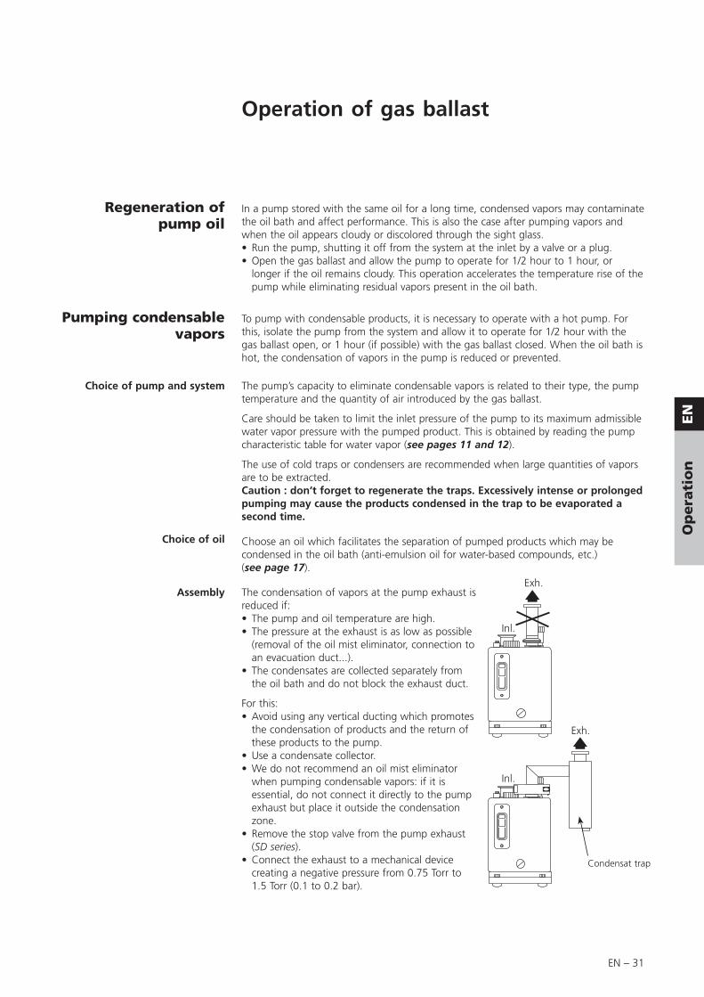
Assembly The condensation of vapors at the pump exhaust is reduced if:• The pump and oil temperature are high.• The pressure at the exhaust is as low as possible
(removal of the oil mist eliminator, connection to an evacuation duct...).
• The condensates are collected separately from the oil bath and do not block the exhaust duct.
For this:• Avoid using any vertical ducting which promotes
the condensation of products and the return of these products to the pump.
• Use a condensate collector.• We do not recommend an oil mist eliminator
when pumping condensable vapors: if it is essential, do not connect it directly to the pump exhaust but place it outside the condensation zone.
• Remove the stop valve from the pump exhaust (SD series).
• Connect the exhaust to a mechanical device creating a negative pressure from 0.75 Torr to 1.5 Torr (0.1 to 0.2 bar).
Inl.
Exh.
Inl.
Exh.
Condensat trap

EN – 32
Vapor pumping procedure • Isolate the pump from the system and increase the pump temperature, 30 minutes with gas ballast (see page 31).
• Start pumping and check the oil level:- The oil level drops, oil is being lost, add oil in the pump.- The oil level rises; condensates have been added into the oil.
• After pumping, let the pump running at ultimate pressure and condensates will be separate from the oil.- If the oil is cloudy or discoloured, change the oil.- If the condendates are heavier than the oil, drain them by the oil drain port.- If the condensates are lighter than the oil, drain the pump, flush the pump with clean oil. Let the mixture to clarify, than recover the oil.
Pumping condensablevapors (cont’d)

EN – 33
EN
Op
era
tio
n
Purges for pumping condensable, corrosive, and hazardous gases
C1 and C2 SeriesPurges The use of vane pumps may result in pumping gases or vapors which are flammable
or that could contaminate the oil. In this case, these products must be diluted using purges supplied with dry gases, such as nitrogen to avoid undesirable reactions.
For this purpose, a filtered dry nitrogen supply or other inert gas with the same characteristics is required:• condensation point < 72°F/22°C,• dust < 1μm,• minimum absolute pressure 2 bar,• H2O concentration < 10 ppb,• O2 concentration < 5 ppb.
Oil case purge The purge dilutes pumped gases with a inert gas.It makes it possible to limit corrosion in the oil case, condensation and accumulation of gases in dead spaces of the pump.Furthermore, the purge allows to flush with gas the pipes and accessories connected at the exhaust of the pump.
Connect the dry nitrogen supply on the specific connector (1/8 NPT).
Set the nitrogen pressure to approximately 15.4 PSIG (1.1 absolute bar) (see table page 34), and the flowrate so as to satisfy the dilution conditions. (Caution: do not generate an excess pressure > 7 PSIG (0.5 relative bar).
Purge with gas ballast Because of the danger present if the gas ballast was to be opened to astmosphere (C2 series), the manual gas ballast doesn’t operate. Connect the dry nitrogen on the specific connector (1/8 NPT). The nitrogen flowrate should be adjusted according to the values from table page 34.
C2 SeriesUse of the bubbler The bubble device is composed of an air tube with several holes, located at the bottom
of the oil case, which releases bubbles of inert gas in the oil. In this way, the oil is saturated with neutral gas, which reduces its capacity to dissolve pumped gases. The bubbles of inert gas released make it possible to eliminate the volatile vapours or acids condensed in the oil. The bubbler flow also lowers the pumps temperature which slows corrosion.
Connect the dry nitrogen supply on the specific connector (1/8 NPT).
Setting The gas flow rate is adapted according to the application and the installation, taking the following criteria into account (flow 60 to 300 l/h) (see table page 34):
• When pumping high quantities of gas, a highly corrosive gas or an easily condensable gas, it is recommended to use a high nitrogen flow rate.Caution ! It is assumed that a sufficient quantity of nitrogen is available.
• The pump exhaust circuit must be such that, for discharged flow rates, pressure drops do not cause an abnormal excess pressure in the oil case.
• The nitrogen flow rate must be such that oil loses have no effect on the operation of the pump throughout the pumping cycle (the oil level must be above the lower limit of the sight glass at the end of pumping).
Run the pump at ultimate vacuum for one hour and set the nitrogen flow rate as follows (at atmospheric pressure and at 60°F/20°C).

EN – 34
Note: these characteristics apply for pumps operating at a constant inlet pressure (1 to 5 mbar): they are adapted for each case of pumping.
Start-up Isolate the pump from the pumping line (close the isolation valve at inlet).Start up the pump at ultimate vacuum. When it is hot, open the nitrogen purge and adjust the flow.Wait for the pump stabilization.Open the inlet valve and pump on corrosive gases: check that the purge in running during all the pumping time.
Using the two purges simultaneously
(C2 series)
When the bubbler and the oil casing purge are used simultaneously, the gas flow rate must be ajusted to suit the application and the installation. The adjustment data given in the table corresponds to the adding flow adjustment data.
Stop Isolate the pump from the pumping line (close the isolation valve).When pumping stops, allow the purge to operate for approximately 1 hour (depending on the quantity of pumped gas) at ultimate vacuum, with the purge, in order to degas the oil effectively and clean the pump with nitrogen to eliminate the traces of pumped gases.Stop the purge but let the pump running to avoid any condensation, or dampness introduction that can react with pumped gases.If the pump must be stopped, prepare it as described on page 16 to store a pump which has been used.
Purge and sensor setting table
Purges for pumping condensable, corrosive, and hazardous gases (cont’d)
Setting
Model Item DescriptionNeutral gas flow (l/h) Pressure (bars)
T (°C)
Corresponding absolute pressure
(bar)(indicative value)
mini average maxi Starting Operating Problem
2033
2063C1/C2 1 Gas ballast purge
1200
1500
1500
1700
2000
2500- - 1.1 to 1.25
2033
2063C1/C2 2 Oil casing purge
60
70
300
300
700
900- -
1.1 to 1.25
1.15 to 1.25
2033
2063C2 3 Oil pressure sensor connection * - 0.9 1.2 ± 0.1 < 0.8 - -
2033
2063C2 4 Purge - Bubbler
60
70
300
300
700
900- -
1.1 to 1.25
1.15 to 1.25
2033
2063C2 5 Oil temperature sensor connection * - - < 95 °C -
* Sensors are customer supplied.
C2 Series C1 series
Operation principle

EN – 35
EN
Op
era
tio
n
Oxygen pumping
In certain applications, mixtures containing oxygen at different concentrations, or even pure oxygen, are used.
Oils of mineral origin are combustible. Exposure to pure oxygen at high temperatures may cause them to self-ignite. In addition, they are highly oxidized during pumping and quickly lose their lubricating properties.
Mineral oils must not be used for oxygen levels of over 21 % in pumped gases. In this case, perfluorinated synthetic oils must be used (see page 17).
The use of these oils requires a special pump preparation (see page 42). The pump must be completely disassembled and all traces mineral oil removed. Flushing the oil case is not adequate.
Any accumulation of oxygen in the installation should be avoided and the oxygen or combustible mixture should be diluted with a neutral gas at the exhaust: the gas flow rate should be 4 times the oxygen flow rate.
Certain combustible or explosive gases require a higher degree of dilution. Our Support Services and Customer Services can advise you to help solve problems of this kind.
It is strongly recommended not to use fluids such as tri-aryl-phosphate-ester which are known to cause accidents.
EN – 36
Recovery of oil (high pressure and cycling)
For intermittentpumping
When the pump operates at high pressure, the oil heats up, becomes more fluid and is flushed out of the functional block by the gas stream.
Oil losses at the exhaust are increased.
For cyclical pumping or continuous
pumping at high pressure
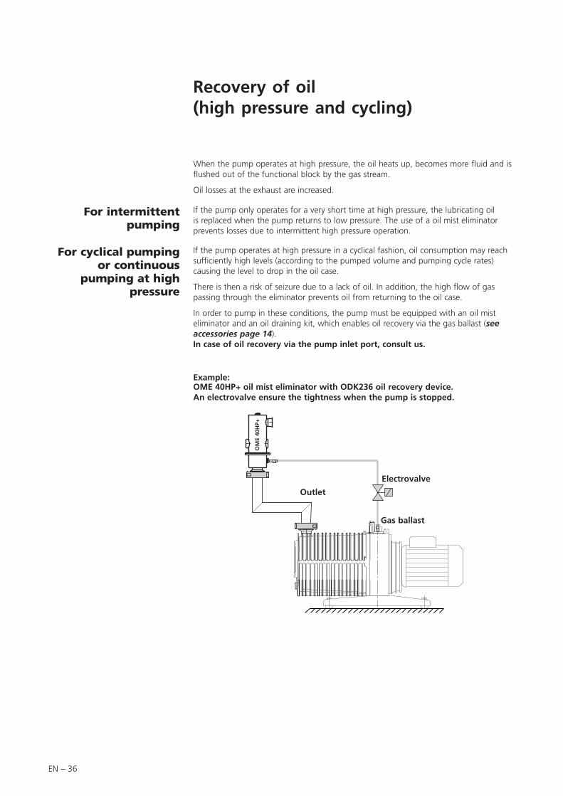
Example:OME 40HP+ oil mist eliminator with ODK236 oil recovery device.An electrovalve ensure the tightness when the pump is stopped.
If the pump only operates for a very short time at high pressure, the lubricating oil is replaced when the pump returns to low pressure. The use of a oil mist eliminator prevents losses due to intermittent high pressure operation.
If the pump operates at high pressure in a cyclical fashion, oil consumption may reach sufficiently high levels (according to the pumped volume and pumping cycle rates) causing the level to drop in the oil case.
There is then a risk of seizure due to a lack of oil. In addition, the high flow of gas passing through the eliminator prevents oil from returning to the oil case.
In order to pump in these conditions, the pump must be equipped with an oil mist eliminator and an oil draining kit, which enables oil recovery via the gas ballast (see accessories page 14).In case of oil recovery via the pump inlet port, consult us.
Outlet
Gas ballast
Electrovalve
OM
E 40
HP+
EN – 37
EN
Main
ten
an
ce
General precautions
Safety instructions for maintenance
For normal operation, the maintenance of 2033-2063 m3/h series pumps only require regular oil changes (see page 41).
Insufficient tightness after servicing could result in chemical hazards. Always perform a leak test after maintenance.
Certain gases can become corrosive and toxic when trapped in oil. Always wear protective gloves when handling used and dirty pump oil, drain it into a closable container, and do not breathe the oil fumes. Always use fully self-contained breathing apparatus.
During pump removal, draining or maintenance operator could be in contact with process residues which could cause severe injury or death. Ask your safety department for instructions according to the local regulations.
We recommend to: - To purge the pumping installation with dry nitrogen. - Wear gloves, protective glasses and, if required for the used gases, a
breathing mask. - Ventilate the premises well.
- Do not eliminate maintenance waste via standard disposal channels. Have it destroyed by a qualified company if necessary.
- Install the inlet and exhaust blanking plates, thus accessories are delivered with the pump.
Decontamination – product dismantlingAccording to the regulations 2002/96/CE about Waste of electrical andelectronical equipments, and 2002/95/CE about Restriction of Hazardoussubstances, the manufacturer provides a recycling paid service for theend of-life of waste electrical and electronic equipment.Any obligation of the manufacturer to take back such equipment shallapply only to complete not amended or modified equipment, using adixen Vacuum Products original spare parts, delivered by adixen, containing i.e. all its components and sub-assemblies.This obligation will not cover the shipping cost to an adixen take backfacility.
If you return the product to an adixen repair service center, please make sure you follow the «procedure for returning products» and fill in the declaration of contamination found in the end of the manual or on the website.
Maintenance must be performed by a skilled maintenance operator trained in the relevant health and safety aspects (EMC, electrical hazards, chemical pollution, etc.).Isolate the product from all energy sources (mains electricity, compressed air, etc.) before starting work.
EN – 38
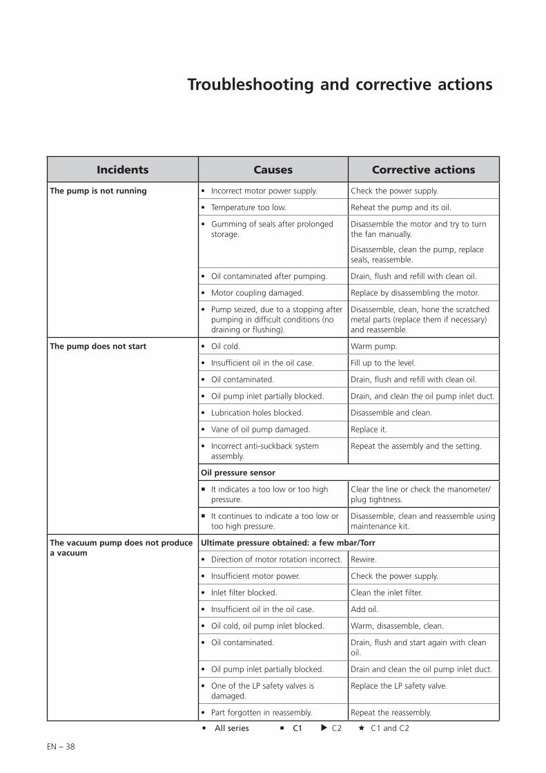
Incidents Causes Corrective actions
The pump is not running Incorrect motor power supply.• Check the power supply.
Temperature too low.• Reheat the pump and its oil.
Gumming of seals after prolonged storage.
• Disassemble the motor and try to turn the fan manually.
Disassemble, clean the pump, replace seals, reassemble.
Oil contaminated after pumping.• Drain, flush and refill with clean oil.
Motor coupling damaged.• Replace by disassembling the motor.
Pump seized, due to a stopping after pumping in difficult conditions (no draining or flushing).
• Disassemble, clean, hone the scratched metal parts (replace them if necessary) and reassemble.
The pump does not start Oil cold.• Warm pump.
Insufficient oil in the oil case.• Fill up to the level.
Oil contaminated.• Drain, flush and refill with clean oil.
Oil pump inlet partially blocked.• Drain, and clean the oil pump inlet duct.
Lubrication holes blocked.• Disassemble and clean.
Vane of oil pump damaged.• Replace it.
Incorrect anti-suckback system assembly.
• Repeat the assembly and the setting.
Oil pressure sensor
It indicates a too low or too high pressure.
Clear the line or check the manometer/plug tightness.
It continues to indicate a too low or too high pressure.
Disassemble, clean and reassemble using maintenance kit.
The vacuum pump does not produce a vacuum
Ultimate pressure obtained: a few mbar/Torr
Direction of motor rotation incorrect.• Rewire.
Insufficient motor power.• Check the power supply.
Inlet filter blocked.• Clean the inlet filter.
Insufficient oil in the oil case.• Add oil.
Oil cold, oil pump inlet blocked.• Warm, disassemble, clean.
Oil contaminated.• Drain, flush and start again with clean oil.
Oil pump inlet partially blocked.• Drain and clean the oil pump inlet duct.
One of the LP safety valves is damaged.
• Replace the LP safety valve.
Part forgotten in reassembly.• Repeat the reassembly.
Troubleshooting and corrective actions
All series C1 C2 C1 and C2
EN – 39
EN
Main
ten
an
ce
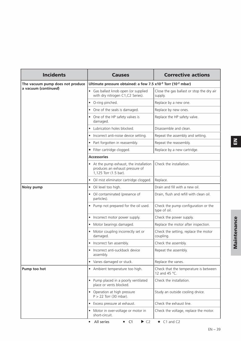
Incidents Causes Corrective actions
The vacuum pump does not produce a vacuum (continued)
Ultimate pressure obtained: a few 7.5 x10⁻³ Torr (10-2 mbar)
Gas ballast knob open (or supplied with dry nitrogen C1,C2 Series).
• Close the gas ballast or stop the dry air supply.
O-ring pinched.• Replace by a new one.
One of the seals is damaged.• Replace by new ones.
One of the HP safety valves is damaged.
• Replace the HP safety valve.
Lubrication holes blocked.• Disassemble and clean.
Incorrect anti-noise device setting.• Repeat the assembly and setting.
Part forgotten in reassembly.• Repeat the reassembly.
Filter cartridge clogged. Replace by a new cartridge.
Accessories
At the pump exhaust, the installation produces an exhaust pressure of 1,125 Torr (1.5 bar).
• Check the installation.
Oil mist eliminator cartridge clogged.• Replace.
Noisy pump Oil level too high.• Drain and fill with a new oil.
Oil contaminated (presence of particles).
• Drain, flush and refill with clean oil.
Pump not prepared for the oil used.• Check the pump configuration or the type of oil.
Incorrect motor power supply.• Check the power supply.
Motor bearings damaged.• Replace the motor after inspection.
Motor coupling incorrectly set or damaged.
• Check the setting, replace the motor coupling.
Incorrect fan assembly.• Check the assembly.
Incorrect anti-suckback device assembly.
• Repeat the assembly.
Vanes damaged or stuck.• Replace the vanes.
Pump too hot Ambient temperature too high.• Check that the temperature is between 12 and 45 °C.
Pump placed in a poorly ventilated place or vents blocked.
• Check the installation.
Operation at high pressureP > 22 Torr (30 mbar).
• Study an outside cooling drvice.
Excess pressure at exhaust.• Check the exhaust line.
Motor in over-voltage or motor in short-circuit.
• Check the voltage, replace the motor.
All series C1 C2 C1 and C2
EN – 40
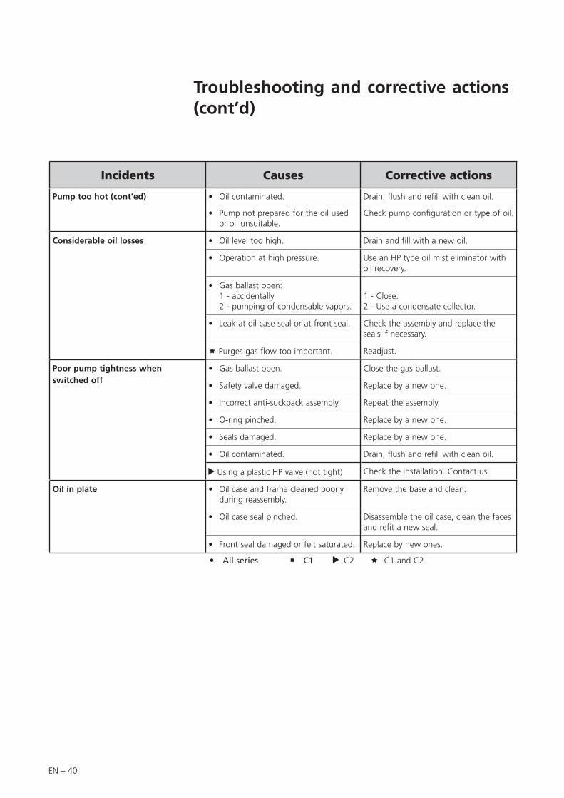
Incidents Causes Corrective actions
Pump too hot (cont’ed) Oil contaminated.• Drain, flush and refill with clean oil.
Pump not prepared for the oil used or oil unsuitable.
• Check pump configuration or type of oil.
Considerable oil losses Oil level too high.• Drain and fill with a new oil.
Operation at high pressure.• Use an HP type oil mist eliminator with oil recovery.
Gas ballast open: 1 - accidentally 2 - pumping of condensable vapors.
•1 - Close.2 - Use a condensate collector.
Leak at oil case seal or at front seal.• Check the assembly and replace the seals if necessary.
Purges gas flow too important. Readjust.
Poor pump tightness whenswitched off
Gas ballast open.• Close the gas ballast.
Safety valve damaged.• Replace by a new one.
Incorrect anti-suckback assembly.• Repeat the assembly.
O-ring pinched.• Replace by a new one.
Seals damaged.• Replace by a new one.
Oil contaminated.• Drain, flush and refill with clean oil.
Using a plastic HP valve (not tight) Check the installation. Contact us.
Oil in plate Oil case and frame cleaned poorly during reassembly.
• Remove the base and clean.
Oil case seal pinched.• Disassemble the oil case, clean the faces and refit a new seal.
Front seal damaged or felt saturated.• Replace by new ones.
All series C1 C2 C1 and C2
Troubleshooting and corrective actions (cont’d)

EN – 41
EN
Main
ten
an
ce
Maintenance
Maintenance frequency
Frequency Operating conditions
Oil6 months “normal”, 24h per day
1 year “normal”, < 12h per day
Pump1 year “normal”, 24h per day
2 years “normal”, < 12h par day
The frequency values are minimum values for «normal» operating conditions: pressure < 1 mbar (0.75 Torr), clean and non-corrosive gas.
An incorrect ultimate vacuum or a reduction in pumping speed are signs that the oil has deteriorated.
The periodic inspection of the state of the oil is performed by comparison with a sample of new oil in order to check the level of contamination or deterioration of the lubricant.
The frequency at which oil is renewed is adapted to the type of operation:
If the oil is cloudy, this indicates that condensables have been absorbed during pumping. The oil can be regenerated using the gas ballast (see page 31).
A thickening of the oil, together with a blackish color and a “burnt” smell indicate that the oil has deteriorated. Drain the pump and flush it.
When the lubricating oil is expensive (fluorocarbon synthetic oils), the use of an oil mist eliminator allows oil recovery after deposition.
The oil should be changed every 6 months. This value is given as a guide only.It may be extended to 1 year if the ultimate vacuum required is sufficient (for roughing pumps).
Similarly, if the pump is stopped frequently for long periods, the oil should be changed at intervals of 6 months to a maximum of 1 year (oil may become sticky).
Note: Every pumping operation is different. This oil must therefore be changed at intervals adapted to each specific application.The use of accessories (see page 14) can reduce the frequency of these maintenance operations.
Roughing
Maintenance of the accessoiries
When an adixen accessory is connected to the pump, periodically it is necessary to make accessory overhaul.Study the accessory user’s manual and make sure you follow the safety instructions it gives regarding protection of personnel: operator could be in contact with process residues on the exhaust which could cause severe injury or death. Ask your safety department for instructions according to the local regulations.
When an oil mist eliminator is installed, check periodically at the exhaust orifice that:- the exhaust valve can move, so the exhaust is not blocked,- the exhaust valve can move, no overpressure in the oil casing.
EN – 42
Draining
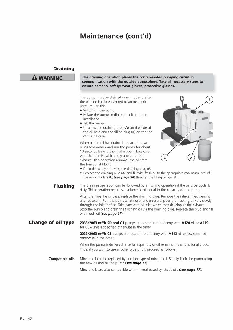
The pump must be drained when hot and after the oil case has been vented to atmospheric pressure. For this: Switch off the pump. Isolate the pump or disconnect it from the installation.
Tilt the pump. Unscrew the draining plug (A) on the side of the oil case and the filling plug (B) on the top of the oil case.
When all the oil has drained, replace the two plugs temporarily and run the pump for about 10 seconds leaving the intake open. Take care with the oil mist which may appear at the exhaust. This operation removes the oil from the functional block. Drain this oil by removing the draining plug (A). Replace the draining plug (A) and fill with fresh oil to the appropriate maximum level of the oil sight glass (C) (see page 20) through the filling orifice (B).
The draining operation places the contaminated pumping circuit in communication with the outside atmosphere. Take all necessary steps to ensure personal safety: wear gloves, protective glasses.
Flushing The draining operation can be followed by a flushing operation if the oil is particularly dirty. This operation requires a volume of oil equal to the capacity of the pump.
After draining the oil case, replace the draining plug. Remove the intake filter, clean it and replace it. Run the pump at atmospheric pressure, pour the flushing oil very slowly through the inlet orifice. Take care with oil mist which may develop at the exhaust. Stop the pump and drain the flushing oil via the draining plug. Replace the plug and fill with fresh oil (see page 17).
B
C A
2033/2063 m3/h SD and C1 pumps are tested in the factory with A120 oil or A119 for USA unless specified otherwise in the order.
2033/2063 m3/h C2 pumps are tested in the factory with A113 oil unless specified otherwise in the order.
When the pump is delivered, a certain quantity of oil remains in the functional block.Thus, if you wish to use another type of oil, proceed as follows:
Change of oil type
Mineral oil can be replaced by another type of mineral oil. Simply flush the pump using the new oil and fill the pump (see page 17).
Mineral oils are also compatible with mineral-based synthetic oils (see page 17).
Compatible oils
Maintenance (cont’d)
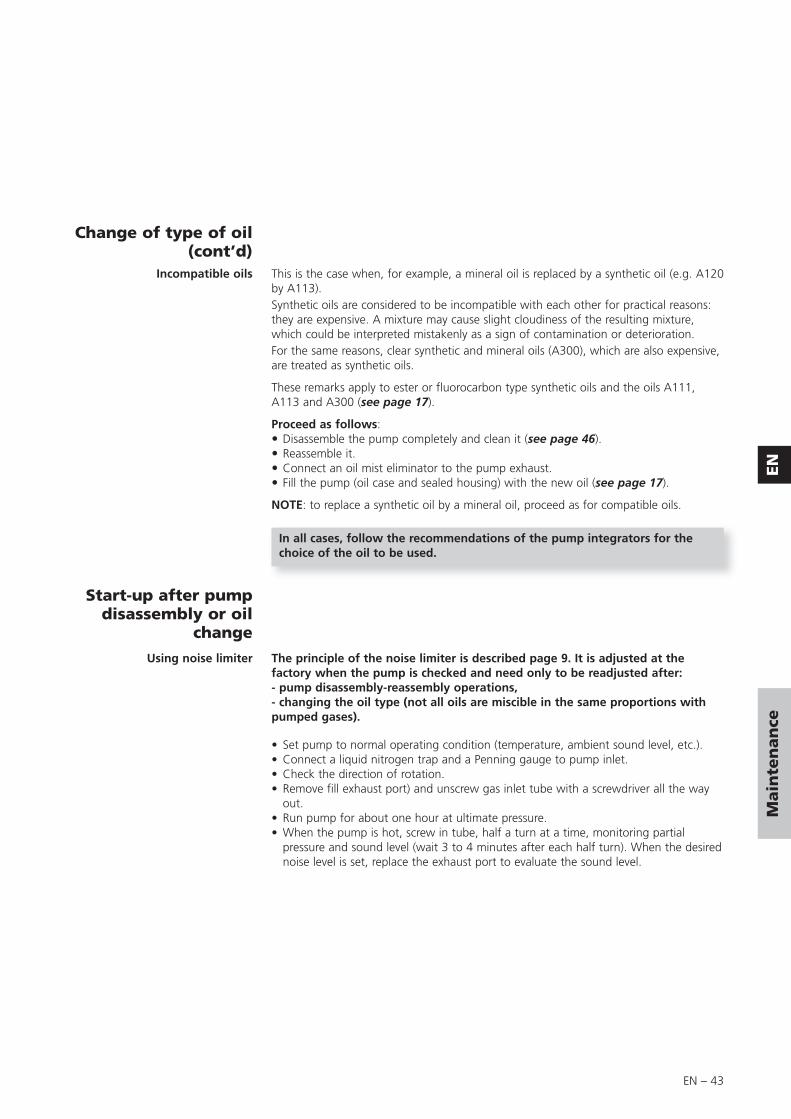
EN – 43
EN
Main
ten
an
ce
This is the case when, for example, a mineral oil is replaced by a synthetic oil (e.g. A120 by A113).Synthetic oils are considered to be incompatible with each other for practical reasons: they are expensive. A mixture may cause slight cloudiness of the resulting mixture, which could be interpreted mistakenly as a sign of contamination or deterioration.For the same reasons, clear synthetic and mineral oils (A300), which are also expensive, are treated as synthetic oils.
These remarks apply to ester or fluorocarbon type synthetic oils and the oils A111, A113 and A300 (see page 17).
Proceed as follows: Disassemble the pump completely and clean it (see page 46). Reassemble it. Connect an oil mist eliminator to the pump exhaust. Fill the pump (oil case and sealed housing) with the new oil (see page 17).
NOTE: to replace a synthetic oil by a mineral oil, proceed as for compatible oils.
Incompatible oils
In all cases, follow the recommendations of the pump integrators for the choice of the oil to be used.
Change of type of oil (cont’d)
Using noise limiter
• Set pump to normal operating condition (temperature, ambient sound level, etc.).• Connect a liquid nitrogen trap and a Penning gauge to pump inlet.• Check the direction of rotation.• Remove fill exhaust port) and unscrew gas inlet tube with a screwdriver all the way
out.• Run pump for about one hour at ultimate pressure.• When the pump is hot, screw in tube, half a turn at a time, monitoring partial
pressure and sound level (wait 3 to 4 minutes after each half turn). When the desired noise level is set, replace the exhaust port to evaluate the sound level.
Start-up after pump disassembly or oil
change
The principle of the noise limiter is described page 9. It is adjusted at the factory when the pump is checked and need only to be readjusted after:- pump disassembly-reassembly operations,- changing the oil type (not all oils are miscible in the same proportions with pumped gases).

EN – 44
Tools and consumable products
Special precautions
Major kit
Spare parts
This kit contains all the seals on the pump which must be replaced at each complete disassembly. It includes the flat gasket for oil casing (on former pumps) but also the o-ring for the new models.
Keep this kit in a dry place, away from heat and light (sunlight and ultraviolet light), in order to prevent any hardening of the elastomers (see AFNOR standards: “storage conditions for vulcanized elastomer based products” - FD T.46 022).
Read the safety instructions at the beginning of the maintenance chapter.Before disassembling the pump, drain it (see page 42).All the seals and faulty parts should be replaced: provide a seal kit or a maintenance kit.
Minor kit
For fasted service, specify the following when ordering:- Pump type.- Serial number (on pump label).- Part number (see list at end of manual).
Maintenance kits containing the most frequently used parts are always available at our sales outlets. Be sure to use these kits so you will have all the parts necessary.
Screw kit This kit contains all screws and washers for the pump.
Pump models P/N
2033 SD 054285
2063 SD 054485
2033 C1 054286
2063 C1 054488
2033 C2 065123
2063 C2 065552
Pump models P/N
2033 SD 054288
2063 SD 054487
2033 C1 054289
2063 C1 054489
2033 C2 065124
2063 C2 065553
Pump models P/N
2033 / 2063 SD 105347
2033 / 2063 C1 - C2 105348
In addition to the seal kit, this kit contains a set of spare parts to perform maintenance operations on the pump for a two year period, under normal operating conditions.

EN – 45
EN
Main
ten
an
ce
Recommended tools The tools required for disassembling and reassembling the motor pump asssembly are listed below:
• N° 3 and N° 9 flat screwdrivers
• Thin spanner- All models: 12 - 13 - 16 - 17 mm on face - C1: 14 - 16 - 50 mm on face- C2: 14 - 16 - 19 mm on face
• Allen wrenches: 2 - 4 - 5 - 6 - 8 mm
• 8mm extraction screws
• Filter cartridge key - automobile equipment supplier - (C1 serie)
Tools kit
This kit contains the usefull tools to disassemble and reassemble the shaft seals in the different flanges and flanged stators.
Specific tools
DESCRIPTION P/N
For all pump models, kit including: 065192
Mounting mandrel 19.5 mm 065089
Protective sleeve 065088
Washer 073331
Coupling adjustment tool 065087
Extraction tool 065186

EN – 46
Disassembling the pump
Disassembling the motor block
(see page N-2)
Unscrew 4 nuts (16) and washers (15).Remove motor assembly (C) and motor mounting plate (22). The coupling separates into two halves, one (2) (N-12) on the motor side, the other (1) (N-12) on the pump side.
Follow the chronological order of disassembling instructions.See the drawings and their part lists in pages N – 1 to N – 13
Disassembling of the fan Prevent fan (17) from rotating by wedging a wooden shim against the side of the frame and two blades of the fan.Remove elastomere coupling (1) (N-12).Unscrew self-locking srew (19) (not reusable) and remove washer (18).Using two M8 mm extraction screws, remove fan (17) and shim.Remove screws (26) and washers (27).Using two M8 mm extraction screws, remove cover (13) with double lip seal (12).
Removing pump fromsystem
The following steps are necessary to protect the pump as far as possible from the effects of corrosion:
• Flush pump with a neutral gas (dry nitrogen) during half an hour to prevent toxic or corrosive gases accumulating in the pump.
• C2 Model: Disconnect the nitrogen lines to the pump. If the sensors are connected, disconnect them.
• Disconnect the pump from the system and seal off the inlet and exhaust ports. Bring the pump to the maintenance area immediately.
• Drain pump (see page 42).
The first phase of disassembly is to disassemble the motor, the second is to disassemble the pumping module.
In case of important pollution, roughly clean the pump with hot solvents under pressure.
C2 Model
Dismantling gas ballast(see page N-10)
Remove three screws (22) then (23), (40) and remove gas ballast assembly (25) andO-ring (26).Unscrew plug (41) (1/8“ NPT).Remove PTFE tape from plug thread (41) and put new one when reassembling.
Remove the fastening screw (19) (C1 model) from the gas ballast knob (20) and unscrew it completely, then remove the spring (21) (SD model) and the O-ring (24).Remove the 3 screws (22) then (23), then remove the gas ballast assembly (25) and the O-ring (26).Valve (27)/valve support (28)/washer (29)/circlip (30) are not easy to disassemble. All parts are available in an equipped gas ballast sub-assembly (see N-11).
Do not store a pump in this condition for any length of time: once the neutral gas has dissipated, the inside of the oil case will be in contact with the ambient air laden with water vapor; this may react with the pumped gases to form acids that may corrode the pump even at room temperature.
C2 Model
SD/C1 Model
Study the general precautions listed on Maintenance chapter page 37.
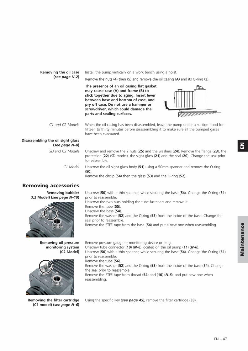
EN – 47
EN
Main
ten
an
ce
Removing the oil case(see page N-2)
Install the pump vertically on a work bench using a hoist.
Remove the nuts (4) then (5) and remove the oil casing (A) and its O-ring (3).
The presence of an oil casing flat gasket may cause case (A) and frame (B) to stick together due to aging. Insert lever between base and bottom of case, and pry off case. Do not use a hammer or screwdriver, which could damage the parts and sealing surfaces.
Disassembling the oil sight glass(see page N–8)
C1 and C2 Models When the oil casing has been disassembled, leave the pump under a suction hood for fifteen to thirty minutes before disassembling it to make sure all the pumped gases have been evacuated.
Removing accessoriesUnscrew (50) with a thin spanner, while securing the base (54). Change the O-ring (51) prior to reassemble.Unscrew the two nuts holding the tube fasteners and remove it.Remove the tube (55).Unscrew the base (54).Remove the washer (52) and the O-ring (53) from the inside of the base. Change the seal prior to reassemble.Remove the PTFE tape from the base (54) and put a new one when reassembling.
Removing bubbler(C2 Model) (see page N–10)
Removing oil pressure monitoring system
(C2 Model)
Remove pressure gauge or monitoring device or plug.Unscrew tube connector (10) (N-6) located on the oil pump (11) (N-6).Unscrew (50) with a thin spanner, while securing the base (54). Change the O-ring (51) prior to reassemble.Remove the tube (56).Remove the washer (52) and the O-ring (53) from the inside of the base (54). Change the seal prior to reassemble.Remove the PTFE tape from thread (54) and (10) (N-6), and put new one when reassembling.
Removing the filter cartridge (C1 model) (see page N–6)
Using the specific key (see page 45), remove the filter cartridge (33).
Unscrew and remove the 2 nuts (25) and the washers (24). Remove the flange (23), the protection (22) (SD model), the sight glass (21) and the seal (20). Change the seal prior to reassemble.
SD and C2 Models
C1 Model Unscrew the oil sight glass body (51) using a 50mm spanner and remove the O-ring (50).Remove the circlip (54) then the glass (53) and the O-ring (52).

EN – 48
Remove 4 nuts (1) then (2).Insert two screwdrivers into the two notches and twist to remove plate off pins (11).Pull flange (4) straight out, holding HP rotor (9) in place.Remove O-ring (5).
Disassembling the rear flange (4)
C1 model: Remove the 2 screws (32) and remove the case bushing (31).Remove screws (21) then (18) and equipped body (11).Remove screws (20) then (19) and cylinder (17), spring (16), piston (15) and diaphragm (14).Remove seat (13) and O-ring (12). Change the O-ring prior to reassemble.Unscrew the oil inlet tube fixation (3) and (4) and remove the stop (5) (SD and C1 models). Remove the oil inlet tube (1).Unscrew air inlet tube (7) and remove spring (6).If necessary, note settting of air inlet tube (7): number of turns until tube stops moving turning clokwise.Remove vane (9).
Disassembling oil pump (11)(see page N–6)
Removing HP rotor (9) andHP stator (12)
Removing flange (21)
Removing LP rotor (26) and LP stator (29)
Disassembling the pumping module
(see page N-4)Removing the exhaust valve
cover (16) and (32)Remove the screws (18), (17) then (34), (33) and the cover(s) (16), (32).Remove the exhaust valves (13), (30) and their springs (15) (31) and for 63C1 model, the washer (14).
Insert two screwdrivers in the notches of the flange (21) and release the flange (21).Remove the O-ring (24).Remove tube (37) and O-ring (36).
Remove the HP rotor (9) by sliding it out of the HP stator (12).Remove vanes (10) and their springs (39).Insert two screwdrivers in the two notches of the HP stator (12) and twist to remove plate off pins (19).Remove HP stator (12) straight out.Remove the O-ring (20).
SD Model Oil jet (23) lubricates the first stage. Do not remove it for cleaning.When reassembling, spray with compresses air to remove any obstructions.
Remove the LP rotor (26) by sliding it out of the LP stator (29).Remove vanes (27) and their springs (38).Insert two screwdrivers in the two notches of the LP stator (29) and twist to remove plate of pins (7) (N-2).Remove LP stator (29) straight out.Remove the O-ring (35).Remove tube (38) and O-ring (37) (N-2).
19
3
5
20
21
23 22
4
16
14
13
12
19
18
1715
Disassembling the pump (cont’d)

EN – 49
EN
Main
ten
an
ce
Disassembling inlet nipple (9) (see page N-10)
Remove 4 screws (4), (7) then (3), (6) and remove clamps (2) and (5).Remove nipple (9) and its O-ring (8).Remove the metallic filter (31) and clean it.
Remove the pin (7) and the filter (9), the sleeve (8), the shaft (6), the valve (2) and the circlip (5).
Disassembling exhaust nipple (3) (see page N-8)
Remove the protection (1).To remove the exhaust nipple (3), the nipple must be connected to a line with a NW40 centering ring with O-ring and quick connect clamp. Use the quick connect clamp to unscrew the nipple (3).Remove the O-ring (4).
SD Model
Cleaning metal components
Cleaning the oil level sight glass
Solvents are required to clean components.
Standard precautions should be taken in compliance with the manufacturer's instructions.
After use in mineral or synthetic oil, clean the metal components with a mineral products based solvent such as AXAREL(1) , CARECLEAN(2), PREMACLEAN(3), NAPHTESOL(4). Proceed as follows:• clean when cold or hot (max. 45°C) by dipping or using a cloth,• vacuum dry in a ventilated oven,• the component must be cleaned a second time with alcohol.
After use in (perfluorinate) synthetic oil, clean the metal components in a solvent such as GALDEN S 90™(5) and proceed as follows:• clean when cold by dipping or using a cloth,• dry the components in the air or with compressed air.
After use in (non-perfluorinate) synthetic or mineral oil, clean the metal components with a solvent such as alcohol and proceed as follows:• clean when cold by dipping or using a cloth,• dry the components in the air.
Industrial washing solutions can also be used. The cleaning operation should be followed by vacuum drying.
SD, C2 series pump
C1 series pump
When cleaning the plastic sight flass, avoid contact with alcohol or alcohol based washing solutions. Clean the component with a solvent but do not dip it, and rinse it immediately.
Oil casing/frame surfaces cleaning
Replace the oil casing O-ring each time the pump is disassembled.• If the oil casing was equipped with a flat gasket, clean the oil casing and central
housing surfaces by scraping them with a piece of wood or plastic to avoid scratching them. When reassembling, oil the frame and case surfaces lightly.
• If the oil casing was equipped with an O-ring, lubricate it with the grease delivered in the minor kit before reassembling.
The sight glass of these pumps is made of glass. It can be cleaned with commun used solvents.
(1) DUPONT DE NEMOURS registered trademark(2) CASTROL registered trademark(3) DOW registered trademark
(4) Nippon Oil Corporation registered trademark(5) MONTEDISON registered trademark

EN – 50
ø 34.5 ± 0.1
5.5 ± 0.2
(*)ø 19.5 +0.20 1
à 45°
+0.20
Replacement of shaft seals
Recommended tools
• Specific extraction tool.• Specific assembly mandrel.• A support plate (or washer).
Extracting a shaft seal from its housing
Specific tools
• A flat screwdriver.• A hammer.
With the flange flat: the seal is extracted using a screwdriver, resting on the plate (or washer) so as not to damage the seal housing.
washer
Assembling the shaft seal
The seal housing is lubricated with the lubricant used in the pump.The flange is resting on a flat surface.
According to the direction of assembly, the seal is fitted on the assembly mandrel.
Using a press or a hammer, the seal is inserted in its housing.
Check the position of the seal: it must lean against its bearing.
(*) 24.5 mm according to product configuration.
Mandrel
Double lip seal greasing (12)
Use only the grease delivered in the minor kit.
Put some spots of grease between the lips of the seal as shown on the picture.
Spread meticulously the grease to fill in the space between the two lips: be aware to not damage the lips! than remove the excess of grease.
The double lip seal was installed on the mandrel according to the right direction of assembly and fit it into the seal holder (13) (see § Assembling the shaft seal).
Single lip seal greasing The lip of the seal is lubricated with the lubricant used in the pump.
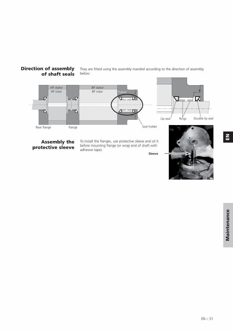
EN – 51
EN
Main
ten
an
ce
Direction of assemblyof shaft seals
Assembly the protective sleeve
To install the flanges, use protective sleeve and oil it before mounting flange (or wrap end of shaft with adhesive tape).
They are fitted using the assembly mandrel according to the direction of assembly below:
Sleeve
BP statorHP statorBP rotorHP rotor Frame
Rear flange Flange Seal holder
Lip seal Double lip sealRings
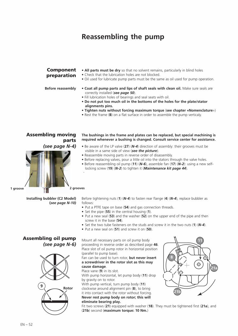
EN – 52
Reassembling the pump
• All parts must be dry so that no solvent remains, particularly in blind holes• Check that the lubrication holes are not blocked.• Oil used for lubricate pump parts must be the same as oil used for pump operation.
Component preparation
Before reassembly • Coat all pump parts and lips of shaft seals with clean oil. Make sure seals are correctly installed (see page 50).
• Fill lubrication holes of bearings and seal seats with oil.• Do not put too much oil in the bottoms of the holes for the plate/stator
alignments pins.• Tighten nuts without forcing maximum torque (see chapter «Nomenclature»)• Rest the frame (B) on a flat surface in order to assemble the pump verticaly.
The bushings in the frame and plates can be replaced, but special machining is required whenever a bushing is changed. Consult service center for assistance.
Assembling moving parts
(see page N-4) • Be aware of the LP valve (27) (N-4) direction of assembly: their grooves must be visible in a same side of view (see the picture).
• Reassemble moving parts in reverse order of disassembly.• Before replacing valves, pour a little oil into the stators through the valve holes.• Before reassembling oil pump (11) (N-6), assemble fan (17) (N-2): using a new self-
locking screw (19) (N-2) to tighten it (Maintenance kit page 44).
Installing bubbler (C2 Model) (see page N-10)
Before tightening nuts (1) (N-4) to fasten rear flange (4) (N-4), replace bubbler as follows:• Put a PTFE tape on base (54) and gas connection threads.• Set the pipe (55) in the central housing (1).• Put a new seal (53) and the washer (52) on the upper end of the pipe and then
screw it in the base (54).• Set the two tube fasteners on the studs and screw it in the two nuts (1) (N-4).• Put a new seal on (51) and screw it on (50).
Assembling oil pump (see page N-6)
9 Rotor
Mount all necessary parts on oil pump body proceeding in reverse order as described page 46.Place slot of oil pump rotor in horizontal position (parallel to pump base).Fan can be used to turn rotor, but never insert a screwdriver in the rotor slot as this may cause damage.Place vane (9) in its slot.With pump horizontal, let pump body (11) drop by gravity on to rotor.With pump vertical, turn pump body (11) clockwise around alignment pin (8), to bring it into contact with the rotor without forcing. Never rest pump body on rotor; this will eliminate bearing play.Fit two screws (21) equipped with washer (18). They must be tightened first (21a), and (21b) second (maximum torque: 10 Nm.)
11
21a
8
21b
1 groove 2 grooves

EN – 53
EN
Main
ten
an
ce
A
Air inlet tube (7) reassembly Install the spring (6) and screw the air inlet tube (7) and unscrew it of the number of turns given, when disassembling (usually 3 or 4 turns) (see page 48).
Motor coupling (see page N-12)
To make sure motor coupling does not touch fan, adjust distance from motor plate (dimension A on the drawing):
To perform this adjustment, use adjusting tool in tool kit (see page 45).
Pump models Dimension «A»
2033 SD - C1 - C2 16.6 ± 0.5 mm
2063 SD - C1 - C2 23.3 ± 0.5 mm
Oil inlet tube (1) reassembly(C2 Model)
When positioning the oil inlet tube (1), make sure that screw is properly centered in the centering hole, the collector located at the upper part of the tube must line up under the oil fill port in the oil casing.
Installing the filter cartridge (33)(C1 model)
Install the case bushing (31) on the oil pump (11) (the direction is defined by the centering pins which allow to have a right oil circulation in the cartridge). Than, screw the filter cartridge (33).
Installing oil pressureindicator
(C2 Model) (see page N-10)
Place a strip of Teflon tape on thread of connectors (54) and (10) (N-6).Position one end of tube (56) in connector (10) (N-6) and the other end in the hole in the frame provided for this purpose.Install a new o-ring (52), the washer (53) on the top end of the tube and screw (54) onthe frame (1).Screw connector (10) (N-6) into oil pump (11) (N-6).Change the O-ring (51) and screw the screw (50).
Installing the oil sight glass(see page N-8)
Install a new flat seal (20) then the sight glass (21), the protection (22) (SD model) and the flange (23).Secure with 2 screws (25) equipped with washers (24) to a maximal torque of 12Nm ± 2 Nm.
After reassembling, fill the oil casing with oil (see page 17) before start-up the pump (see page 29).
Fill with oil
SD, C2 Series
C1 series pump Place the O-ring (52), the glass (53) and the circlip (54) on the Oil sight glass body (51).Place the O-ring (50) and screw the oil sight glass body equipped (51) using a 50 mm spanner.

EN – 54
Declaration of contamination
Procedure for returning adixen products
You wish to return an adixen product for maintenance. The equipment will be dismantled and possibly cleaned by a technician from our service centre. Pfeiffer Vacuum requires this form to be completed to preclude the potential health risk to its service personnel that can occur when receiving, disassembling, or repairing potentially contaminated products..
Please fill in the present DECLARATION OF CONTAMINATION, print it and attach it to the product before shipping to your closest service center.Equipment returned without this form fully completed, and secured to outside of package, will be returned to customer unprocessed, at his cost.If following inspection and quotation, customer elects to not proceed with repair, he will be subject to service fee to cover product decontamination, disassembly, cleaning and evaluation costs.Please contact service center for any further recommendations.
We wish to draw your attention to the following points: Equipment must be drained of fluids and residue, securely packaged and shipped prepaid. Concerning the closing of the ports (inlet & outlets of the product), metallic airtight blank flanges should be used if toxic or copper gases have been pumped.
The risk may be of the following nature:
Chemical: Danger to health, risks of explosion, fire, risks for the environment. Please indicate the chemical formula and name of the gases or substances that have been in contact with the equipment (pump, detector, gauge or accessory).
Biological: In case of contamination (such as pathogenic germs, micro-organisms (bacteria, viruses, etc.) classes 1 to 4 and group E), we are currently unable to decontaminate and recycle such material without risk to the safety of our staff. Please contact us before sending the product to the service center.
Radioactive: In case of contamination, our Service Center is currently unable to decontaminate and recycle such material without risk to the safety of our staff. A written evidence of decontamination will be requested prior to any service action. Please contact us before sending the product to the service center.
Copper contamination: Copper based by-products formed in sputtering or etching processes are considered as a poison in some semi-conductor processes. A specific treatment is required, which generates extra cost.
· Gases (or substances) introduced into the reactor and which may be found at the exhaust (A).
· Gases (or substances) resulting from the reaction or process (B).
· Gases (or substances) that may possibly be formed inside the pump (due to a thermodynamic or chemical reaction, condensation, deposition, precipitation, etc.) (C).
•
•
•
•
In the event of chemical contamination, please indicate the following gases or substances:
Pump
Substances produced by reaction (B)
Gas introduced (A) Exhaust(A)+(B)+(C)
Reactor
Gases reaction (C)

EN – 55
EN
Main
ten
an
ce

EN – 56

N – 1
Nomenclature
Composants de maintenance / Maintenance components / Unterhaltung Teile
Plan de montage cuve et bâti .............................................Oil casing and central housing assembly drawing ....................Gesamtplan Ölbehälter und Pumpenträger ................................... N-2
Nomenclature cuve et bâti ..................................................Oil casing and central housing part list ....................................Nomenklatur Ölbehälter und Pumpenträger ................................. N-3
Plan du bloc fonctionnel (D) ................................................Pumping module drawing (D) ..................................................Gesamtplan Pumpenblock (D) ...................................................... N-4
Nomenclature bloc fonctionnel (D)......................................Pumping module part list (D) ...................................................Nomenklatur Pumpenblock (D) ..................................................... N-5
Plan système de lubrification pompe à huile (E) ..................Oil pump system drawing (E) ...................................................Gesamtplan Ölpumpsystem (E) ..................................................... N-6
Nomenclature système de lubrification ..............................Oil pump system part list (E) ....................................................Nomenklatur Ölpumpsystem (E) ................................................... N-7pompe à huile (E)
Plan de détail cuve (A) ........................................................Oil casing detail drawing (A) .................................................... Einzelplan Ölbehälter (A) .............................................................. N-8
Nomenclature cuve (A) .......................................................Oil casing part list (A) ..............................................................Nomenklatur Ölbehälter (A).......................................................... N-9
Plan de détail bâti (B) ..........................................................Central housing detail drawing (B) ........................................... Einzelplan Pumpenträger (B) ....................................................... N-10
Nomenclature bâti (B) .........................................................Central housing part list (B) .....................................................Nomenklatur Pumpenträger (B) .................................................. N-11
Plan ensemble motorisation (M) ..........................................Motor assembly drawing (M) ...................................................Gesamtplan Motor (M) ............................................................... N-12
Nomenclature ensemble motorisation (M) ...........................Motor assembly part list (M) ....................................................Nomenklatur Motor (M) ............................................................. N-13

N – 2
27
28
29
30
31
32
33
2524
23
11
1314
1516
1718
1920
2122
M
12a
12
34
56
7
B
8
10
ED
3837
26
3435
SD Model
A
10a
9
12C1 Model
C2 model
A B D E M Detailed next pages
Rep. PartClamping torque
(DaN.m)
4/9/16Nut H M8 1.5
Nut H M10 3.0
6
Stud M8-28 ZN10C 1.5
Stud M8-28 SS 1.5
Stud M10-30 3.0
14Stud M8-20 1.5
Stud M10-25 3.0
19 Screw CHC M10-20 4.5
20Screw CHC M8-25 1.5
Screw CHC M8-20 1.5
Plan de montage cuve et bâtiOil casing and central housing assembly drawing Ölbehälter und Pumpenträger Gesamtplan
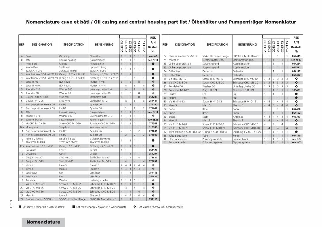
N – 3
Nomenclature
Nomenclature cuve et bâti / Oil casing and central housing part list / Ölbehälter und Pumpenträger Nomenklatur
REP DÉSIGNATION SPECIFICATION BENENNUNG
REF.
P/N
Bestell. Nr20
33 S
D20
63 S
D20
33 C
120
63 C
120
33 C
2
2063
C2
A Cuve Oil casing Ölbehälter 1 1 1 1 1 1 see N-9
B Bâti Central housing Pumpenträger 1 1 1 1 1 1 see N-11
1 Frein d’axe Circlips Achsebremse 1 1 1 1 1 1
2Joint à lèvre20X35X7 FMP81
Shaft seal20X35X7 FMP81
Lippendichtung20X35X7 FMP81
1 1 1 1 1 1
3 Joint torique c 3,53 - d 221,85 O-ring c 3.53 - d 221.85 Dichtung c 3,53 - d 221,85 1 1 1
3 Joint torique c 3,53 - d 278,99 O-ring c 3,53 - d 278,99 Dichtung c 3,53 - d 278,99 1 1 1
4 Ecrou H M8 Nut H M8 Mutter H M8 8 8 8
4 Ecrou H M10 Nut H M10 Mutter H M10 8 8 8
5 Rondelle D10 Washer D10 Unterlegscheibe D10 8 8 8
5 Rondelle D8 Washer D8 Unterlegscheibe D8 8 8 8
6 Goujon M8-28 INOX Stud M8 Stehbolzen M8 8 8 8 054209
6 Goujon M10-25 Stud M10 Stehbolzen M10 8 8 8 054441
7 Pion de positionnement D6 Pin D6 Zylinder D6 2 2 2 071240
7 Pion de positionnement D8 Pin D8 Zylinder D8 2 2 2 071042
B Bâti Central housing Pumpenträger 1 1 1 1 1 1 see N-11
8 Rondelle D10 Washer D10 Unterlegscheiter D10 1 1 1 1 1 1
9 Equerre fixation Square support Winkel Träger 1 1 1 1 1 1 A465526
10 Vis CHC M10 x 30 Screw CHC M10-30 Schraube CHC M10-30 1 1 1 1 1 1 075548
10a Mousqueton Snap hook Karabiner Haken 1 1 118743
11 Pion de positionnement D6 Pin D6 Zylinder D6 2 2 2 071041
11 Pion de positionnement D8 Pin D8 Zylinder D8 2 2 2 071046
12Joint à 2 lèvres20X35X7 FMP81
Double lip seal20X35X7 FMP81
2 Lippendichtung20X35X7 FMP81
1 1 1 1 1 1
12a Joint torique c 2,5 - d 38 O-ring c 2.5 - d 38 Dichtung c 2,5 - d 38 1 1 1 1 1 1
13 Couvercle Cover Deckel 1 1 054126
13 Couvercle Cover Deckel 1 1 1 1 054204
14 Goujon M8-20 Stud M8-20 Stehbolzen M8-20 4 4 4 075837
14 Goujon M10-25 Stud M10-25 Stehbolzen M10-25 4 4 4 075838
15 Idem 5 Idem 5 Ebenso 5 4 4 4 4 4 4
16 Idem 4 Idem 4 Ebenso 4 4 4 4 4 4 4
17 Ventilateur Fan Ventilator 1 1 1 054115
17 Ventilateur Fan Ventilator 1 1 1 054435
18 Rondelle Washer Unterlegscheibe 1 1 1 1 1 119 Vis CHC M10-20 Screw CHC M10-20 Schraube CHC M10-20 1 1 1 1 1 120 Vis CHC M8-25 Screw CHC M8-25 Schraube CHC M8-25 4 4 420 Vis CHC M8-20 Screw CHC M8-20 Schraube CHC M8-20 4 4 421 Idem 8 Idem 8 Ebenso 8 4 4 4 4 4 422 Flasque moteur 50/60 Hz 50/60 Hz motor flange 50/60 Hz Motorflansch 1 1 1 054118
Lot joints / Minor kit / Dichtungssatz Lot maintenance / Major kit / Wartungssatz Lot visserie / Screw kit / Schraubensatz
REP DÉSIGNATION SPECIFICATION BENENNUNG
REF.
P/N
Bestell. Nr20
33 S
D20
63 S
D20
33 C
120
63 C
120
33 C
2
2063
C2
22 Flasque moteur 50/60 Hz 50/60 Hz motor flange 50/60 Hz Motorflansch 1 1 1 054419
M Motor tri Electric motor 3ph. Elektromotor 3ph. 1 1 1 1 1 1 see N-13
23 Grille de protection Screening grid Abschirmgitter 1 1 1 054264
23 Grille de protection Screening grid Abschirmgitter 1 1 1 065511
24 Déflecteur Deflector Deflektor 1 1 1 054147
24 Déflecteur Deflector Deflektor 1 1 1 054432
25 Vis FHC M6-10 Screw FHC M6-10 Schraube FHC M6-10 3 3 3 3 3 3 26 Vis CHC M6-20 Screw CHC M6-20 Schraube CHC M6-20 3 3 3 3 3 327 Rondelle D6 Washer D6 Unterlegscheibe D6 3 3 3 3 3 328 Bouchon 1/8 NPT Plug 1/8 NPT Blindstopf 1/8 NPT 1 1 1 1 1 1 103421
29 Feutre Felt Filz 1 1 129 Feutre Felt Filz 1 1 130 Vis H M10-12 Screw H M10-12 Schraube H M10-12 4 4 4 4 4 431 Idem 5 Idem 5 Ebenso 5 4 4 4 4 4 432 Socle Base Sockel 1 1 1 054408
32 Socle Base Sockel 1 1 1 054102
33 Butée Stop Anschlag 4 4 4 4 4 4 053323
34 Idem 5 Idem 5 Ebenso 5 4 4 4 4 4 435 Vis CHC M8-20 Screw CHC M8-20 Schraube CHC M8-20 4 4 435 Vis CHC M10-20 Screw CHC M10-20 Schraube CHC M10-20 4 4 437 Joint torique c 2,00 - d 8,00 O-ring c 2.00 - d 8.00 Dichtung c 2,00 - d 8,00 1 1 1 1 1 138 Tube porte-joint Tube Röhre 1 1 1 1 1 1 054140D Bloc fonctionnel Pumping module Pumpenblock 1 1 1 1 1 1 see N-5E Pompe à huile Oil pump system Ölpumpsystem 1 1 1 1 1 1 see N-7
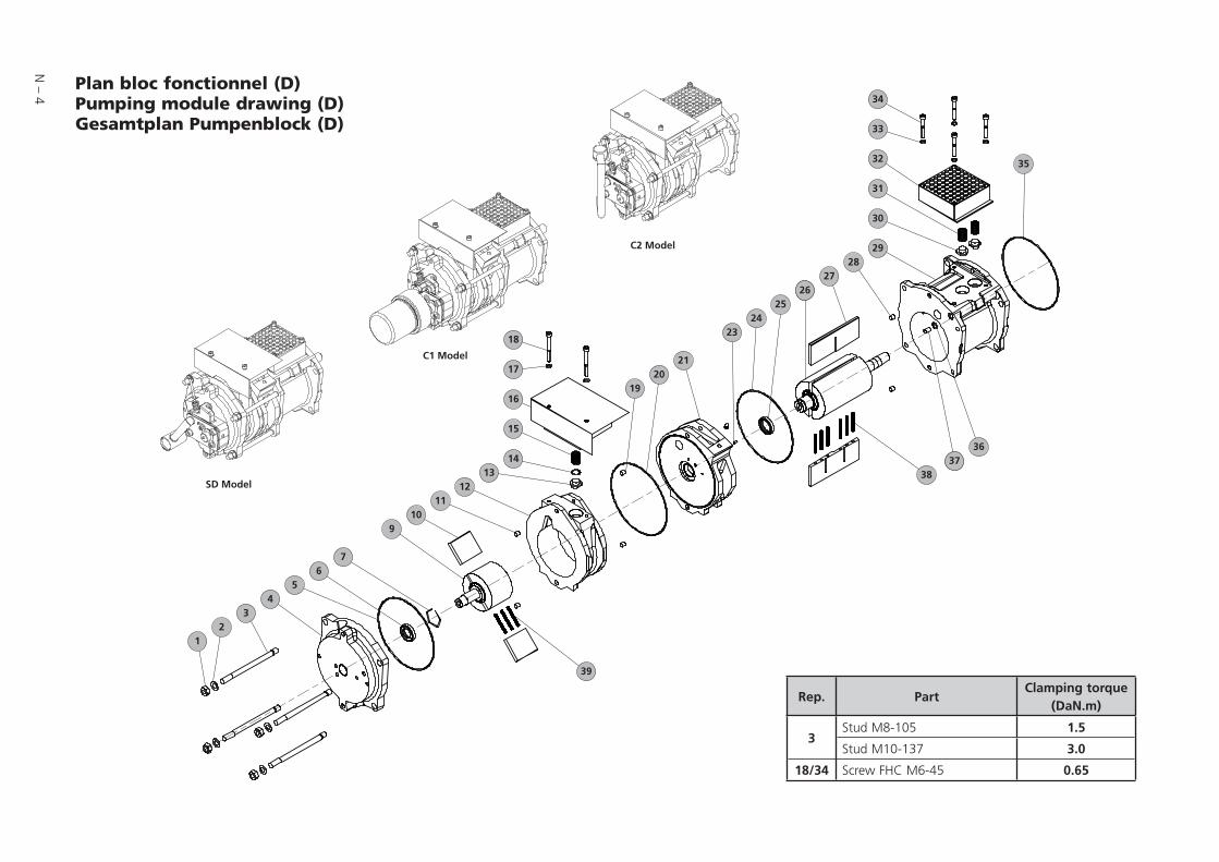
N – 4
Plan bloc fonctionnel (D)Pumping module drawing (D)Gesamtplan Pumpenblock (D)
Rep. PartClamping torque
(DaN.m)
3Stud M8-105 1.5
Stud M10-137 3.0
18/34 Screw FHC M6-45 0.65
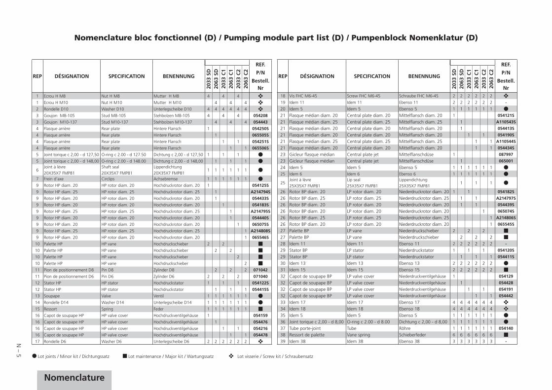
N – 5
NomenclatureNomenclature
Lot joints / Minor kit / Dichtungssatz Lot maintenance / Major kit / Wartungssatz Lot visserie / Screw kit / Schraubensatz
REP DÉSIGNATION SPECIFICATION BENENNUNG
REF.
P/N
Bestell. Nr20
33 S
D20
63 S
D20
33 C
120
63 C
120
33 C
220
63 C
2
1 Ecrou H M8 Nut H M8 Mutter H M8 4 4 4
1 Ecrou H M10 Nut H M10 Mutter H M10 4 4 4
2 Rondelle D10 Washer D10 Unterlegscheibe D10 4 4 4 4 4 4
3 Goujon M8-105 Stud M8-105 Stehbolzen M8-105 4 4 4 054208
3 Goujon M10-137 Stud M10-137 Stehbolzen M10-137 4 4 4 054443
4 Flasque arrière Rear plate Hintere Flansch 1 054250S
4 Flasque arrière Rear plate Hintere Flansch 1 065505S
4 Flasque arrière Rear plate Hintere Flansch 1 1 054251S
4 Flasque arrière Rear plate Hintere Flansch 1 1 065506S
5 Joint torique c 2,00 - d 127,50 O-ring c 2.00 - d 127.50 Dichtung c 2,00 - d 127,50 1 1 1
5 Joint torique c 2,00 - d 148,00 O-ring c 2.00 - d 148.00 Dichtung c 2,00 - d 148,00 1 1 1
6Joint à lèvre20X35X7 FMP81
Shaft seal20X35X7 FMP81
Lippendichtung20X35X7 FMP81
1 1 1 1 1 1
7 Frein d’axe Circlips Achsebremse 1 1 1 1 1 1
9 Rotor HP diam. 20 HP rotor diam. 20 Hochdruckrotor diam. 20 1 054125S
9 Rotor HP diam. 25 HP rotor diam. 25 Hochdruckrotor diam. 25 1 A214794S
9 Rotor HP diam. 20 HP rotor diam. 20 Hochdruckrotor diam. 20 1 054433S
9 Rotor HP diam. 20 HP rotor diam. 20 Hochdruckrotor diam. 20 1 054183S
9 Rotor HP diam. 25 HP rotor diam. 25 Hochdruckrotor diam. 25 1 A214795S
9 Rotor HP diam. 20 HP rotor diam. 20 Hochdruckrotor diam. 20 1 054440S
9 Rotor HP diam. 20 HP rotor diam. 20 Hochdruckrotor diam. 20 1 065075S
9 Rotor HP diam. 25 HP rotor diam. 25 Hochdruckrotor diam. 25 1 A214808S
9 Rotor HP diam. 20 HP rotor diam. 20 Hochdruckrotor diam. 20 1 065546S
10 Palette HP HP vane Hochdruckschieber 2 2
10 Palette HP HP vane Hochdruckschieber 2 2
10 Palette HP HP vane Hochdruckschieber 2
10 Palette HP HP vane Hochdruckschieber 2
11 Pion de positionnement D8 Pin D8 Zylinder D8 2 2 2 071042
11 Pion de positionnement D6 Pin D6 Zylinder D6 2 2 2 071040
12 Stator HP HP stator Hochdruckstator 1 1 1 054122S
12 Stator HP HP stator Hochdruckstator 1 1 1 054415S
13 Soupape Valve Ventil 1 1 1 1 1 1
14 Rondelle D14 Washer D14 Unterlegscheibe D14 1 1 1 1 1 1
15 Ressort Spring Feder 1 1 1 1 1 1
16 Capot de soupape HP HP valve cover Hochdruckventilgehäuse 1 054159
16 Capot de soupape HP HP valve cover Hochdruckventilgehäuse 1 054476
16 Capot de soupape HP HP valve cover Hochdruckventilgehäuse 1 1 054216
16 Capot de soupape HP HP valve cover Hochdruckventilgehäuse 1 1 054478
17 Rondelle D6 Washer D6 Unterlegscheibe D6 2 2 2 2 2 2
REP DÉSIGNATION SPECIFICATION BENENNUNG
REF.
P/N
Bestell. Nr20
33 S
D20
63 S
D20
33 C
120
63 C
120
33 C
220
63 C
2
18 Vis FHC M6-45 Screw FHC M6-45 Schraube FHC M6-45 2 2 2 2 2 2
19 Idem 11 Idem 11 Ebenso 11 2 2 2 2 2 2 -
20 Idem 5 Idem 5 Ebenso 5 1 1 1 1 1 121 Flasque médian diam. 20 Central plate diam. 20 Mittelflansch diam. 20 1 054121S
21 Flasque médian diam. 25 Central plate diam. 25 Mittelflansch diam. 25 1 A110543S
21 Flasque médian diam. 20 Central plate diam. 20 Mittelflansch diam. 20 1 054413S
21 Flasque médian diam. 20 Central plate diam. 20 Mittelflansch diam. 20 1 1 054190S
21 Flasque médian diam. 25 Central plate diam. 25 Mittelflansch diam. 25 1 1 A110544S
21 Flasque médian diam. 20 Central plate diam. 20 Mittelflansch diam. 20 1 1 054434S
23 Gicleur flasque médian Central plate jet Mittelflanschdüse 1 087997
23 Gicleur flasque médian Central plate jet Mittelflanschdüse 1 065001
24 Idem 5 Idem 5 Ebenso 5 1 1 1 1 1 125 Idem 6 Idem 6 Ebenso 6 1 1 1 1 1 1
25Joint à lèvre25X35X7 FMP81
Lip seal25X35X7 FMP81
Lippendichtung25X35X7 FMP81
1 1 1
26 Rotor BP diam. 20 LP rotor diam. 20 Niederdruckrotor diam. 20 1 1 054182S
26 Rotor BP diam. 25 LP rotor diam. 25 Niederdruckrotor diam. 25 1 1 A214797S
26 Rotor BP diam. 20 LP rotor diam. 20 Niederdruckrotor diam. 20 1 1 054439S
26 Rotor BP diam. 20 LP rotor diam. 20 Niederdruckrotor diam. 20 1 065074S
26 Rotor BP diam. 25 LP rotor diam. 25 Niederdruckrotor diam. 25 1 A214806S
26 Rotor BP diam. 20 LP rotor diam. 20 Niederdruckrotor diam. 20 1 065545S
27 Palette BP LP vane Niederdruckschieber 2 2 227 Palette BP LP vane Niederdruckschieber 2 2 228 Idem 11 Idem 11 Ebenso 11 2 2 2 2 2 2 -
29 Stator BP LP stator Niederdruckstator 1 1 1 054120S
29 Stator BP LP stator Niederdruckstator 1 1 1 054411S
30 Idem 13 Idem 13 Ebenso 13 2 2 2 2 2 231 Idem 15 Idem 15 Ebenso 15 2 2 2 2 2 232 Capot de soupape BP LP valve cover Niederdruckventilgehäuse 1 054129
32 Capot de soupape BP LP valve cover Niederdruckventilgehäuse 1 054428
32 Capot de soupape BP LP valve cover Niederdruckventilgehäuse 1 1 054191
32 Capot de soupape BP LP valve cover Niederdruckventilgehäuse 1 1 054442
33 Idem 17 Idem 17 Ebenso 17 4 4 4 4 4 434 Idem 18 Idem 18 Ebenso 18 4 4 4 4 4 435 Idem 5 Idem 5 Ebenso 5 1 1 1 1 1 136 Joint torique c 2,00 - d 8,00 O-ring c 2.00 - d 8.00 Dichtung c 2,00 - d 8,00 1 1 1 1 1 137 Tube porte-joint Tube Röhre 1 1 1 1 1 1 054140
38 Ressort de palette Vane spring Schieberfeder 6 6 6 6 6 639 Idem 38 Idem 38 Ebenso 38 3 3 3 3 3 3 -
Nomenclature bloc fonctionnel (D) / Pumping module part list (D) / Pumpenblock Nomenklatur (D)

N – 6
Plan système de lubrification pompe à huile (E)Oil pump system drawing (E)Ölpumpsystem Gesamtplan (E)
Rep. PartClamping torque
(DaN.m)
20 Screw CHC M5-8 0.4
21 Screw CHC M8-40 1.5
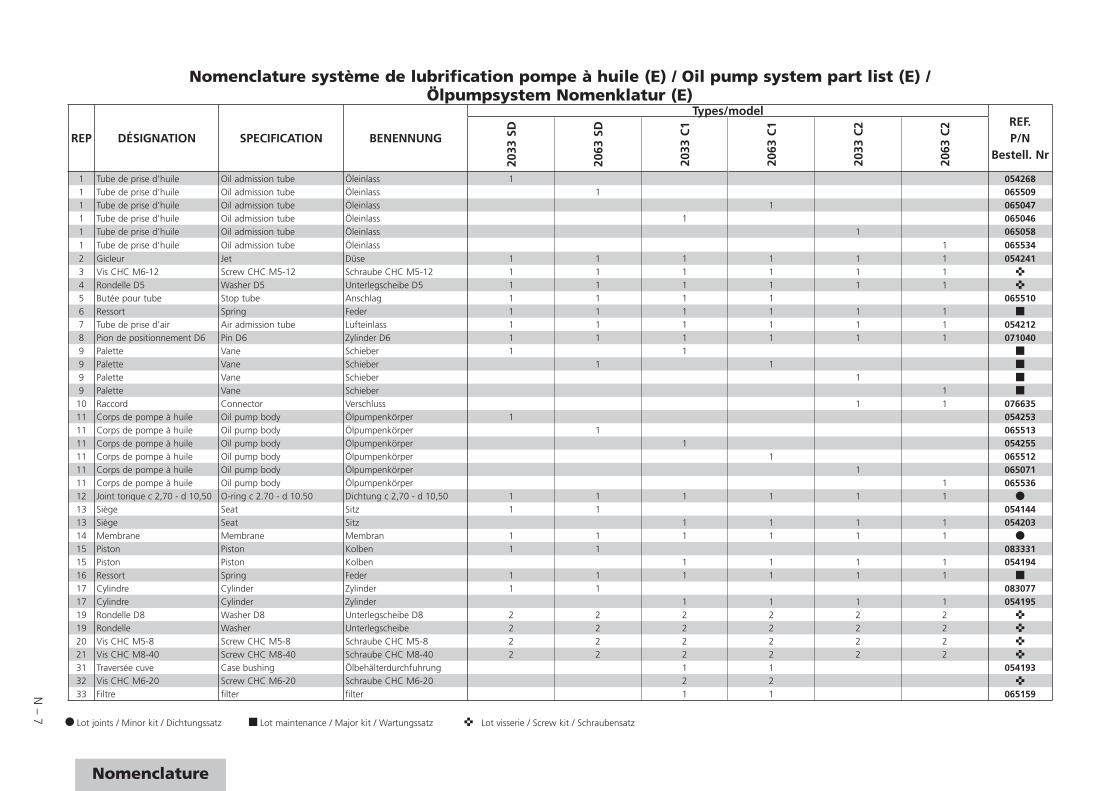
N – 7
Nomenclature
Nomenclature système de lubrification pompe à huile (E) / Oil pump system part list (E) /Ölpumpsystem Nomenklatur (E)
Sous-ensemble A / Subassembly A / Gesamtplan A
REP DÉSIGNATION SPECIFICATION BENENNUNG
Types/modelREF.P/N
Bestell. Nr
2033
SD
2063
SD
2033
C1
2063
C1
2033
C2
2063
C2
1 Tube de prise d'huile Oil admission tube Öleinlass 1 0542681 Tube de prise d'huile Oil admission tube Öleinlass 1 0655091 Tube de prise d'huile Oil admission tube Öleinlass 1 0650471 Tube de prise d'huile Oil admission tube Öleinlass 1 0650461 Tube de prise d'huile Oil admission tube Öleinlass 1 0650581 Tube de prise d'huile Oil admission tube Öleinlass 1 0655342 Gicleur Jet Düse 1 1 1 1 1 1 0542413 Vis CHC M6-12 Screw CHC M5-12 Schraube CHC M5-12 1 1 1 1 1 14 Rondelle D5 Washer D5 Unterlegscheibe D5 1 1 1 1 1 15 Butée pour tube Stop tube Anschlag 1 1 1 1 0655106 Ressort Spring Feder 1 1 1 1 1 17 Tube de prise d’air Air admission tube Lufteinlass 1 1 1 1 1 1 0542128 Pion de positionnement D6 Pin D6 Zylinder D6 1 1 1 1 1 1 0710409 Palette Vane Schieber 1 19 Palette Vane Schieber 1 19 Palette Vane Schieber 19 Palette Vane Schieber 1
10 Raccord Connector Verschluss 1 1 07663511 Corps de pompe à huile Oil pump body Ölpumpenkörper 1 05425311 Corps de pompe à huile Oil pump body Ölpumpenkörper 1 06551311 Corps de pompe à huile Oil pump body Ölpumpenkörper 1 05425511 Corps de pompe à huile Oil pump body Ölpumpenkörper 1 06551211 Corps de pompe à huile Oil pump body Ölpumpenkörper 1 06507111 Corps de pompe à huile Oil pump body Ölpumpenkörper 1 06553612 Joint torique c 2,70 - d 10,50 O-ring c 2.70 - d 10.50 Dichtung c 2,70 - d 10,50 1 1 1 1 1 113 Siège Seat Sitz 1 1 05414413 Siège Seat Sitz 1 1 1 1 05420314 Membrane Membrane Membran 1 1 1 1 1 115 Piston Piston Kolben 1 1 08333115 Piston Piston Kolben 1 1 1 1 05419416 Ressort Spring Feder 1 1 1 1 1 117 Cylindre Cylinder Zylinder 1 1 08307717 Cylindre Cylinder Zylinder 1 1 1 1 05419519 Rondelle D8 Washer D8 Unterlegscheibe D8 2 2 2 2 2 219 Rondelle Washer Unterlegscheibe 2 2 2 2 2 220 Vis CHC M5-8 Screw CHC M5-8 Schraube CHC M5-8 2 2 2 2 2 221 Vis CHC M8-40 Screw CHC M8-40 Schraube CHC M8-40 2 2 2 2 2 231 Traversée cuve Case bushing Ölbehälterdurchfuhrung 1 1 05419332 Vis CHC M6-20 Screw CHC M6-20 Schraube CHC M6-20 2 233 Filtre filter filter 1 1 065159
Lot joints / Minor kit / Dichtungssatz Lot maintenance / Major kit / Wartungssatz Lot visserie / Screw kit / Schraubensatz

N – 8
Plan de détail cuve (A)Oil casing detail drawing (A) Einzelplan Ölbehälter (A)
Rep. PartClamping torque
(DaN.m)
25 Screw CHC M8-20 1.5
30 Screw CHC M6-20 0.65

N – 9
Nomenclature
Nomenclature cuve (A) / Oil casing part list (A) / Nomenklatur Ölbehälter (A)
Lot joints / Minor kit / Dichtungssatz Lot maintenance / Major kit / Wartungssatz Lot visserie / Screw kit / Schraubensatz
REP DÉSIGNATION SPECIFICATION BENENNUNG
REF.
P/N
Bestell. Nr20
33 S
D20
63 S
D20
33 C
120
63 C
120
33 C
220
63 C
2
1 Protecteur plat Flat protector Blindflansche 1 1 1 1 068012
1aAnneau porte-joint DN40 équipé d’un joint
Centering ring with o-ring DN 40 ISO KF
Zentrierring mit Rundschnurring DN 40 ISO KF
1 1 068230
1b Collier de serrage Quick connect clamp Spannring 1 1 083267
1e Obturateur DN 40 ISO KFBlank off flange DN 40 ISO KF
Blindflansche DN 40 ISO KF 1 1 068595
2 Soupape de refoulement Exhaust valve Auspuffventil 1 1
3 Embout de refoulement Exhaust nipple Auspuffstutzen 1 1 054131
3 Embout de refoulement Exhaust nipple Auspuffstutzen 1 1 1 1 054205
4 Joint torique c 3,00 - d 44,00 O-ring c 3.00 - d 44.00 Dichtung c 3,00 - d 44,00 1 1 1 1 1 1
5 Circlips Circlips Klemmen 1 1 054133
6 Axe refoulement Exhaust valve shaft Auspuffventilachse 1 1 054223
7 Goupille Forelock Stift 1 1
8 Rondelle Washer Unterlegscheibe 1 1 073309
9 Filtre de refoulement exhaust filter Auspuff-Filter 1 1 100116
10 Bouchon Fill plug Stopfen 1 1 082925
10 Bouchon Fill plug Stopfen 1 1 1 1 054213
11 Joint torique c 3,00 - d 41,00 O-ring c 3.00 - d 41.00 Dichtung c 3,00 - d 41,00 1 1
11 Idem 4 Idem 4 Ebenso 4 1 1 1 1
15 Cuve Oil case Behälter 1 065158
15 Cuve Oil case Behälter 1 104008
15 Cuve Oil case Behälter 1 065566
15 Cuve Oil case Behälter 1 104008
15 Cuve Oil case Behälter 1 065051
15 Cuve Oil case Behälter 1 065532
20 Joint torique c 3,53 - d 63,10 O-ring c 3.53 - d 63.10 Dichtung c 3,53 - d 63,10 1 1 1 1
21 Verre de voyant Glass Glas 1 1 103307
21 Voyant plastique (PA) Oil sight glass (PA) Glas (PA) 1 1 105452
22 Protection verre Glass protection Glasprotektion 1 1
23 Bride de voyant Oil sight glass flange Ölschauglasklammer 1 1 103308
23 Bride de voyant Oil sight glass flange Ölschauglasklammer 1 1 104483
24 Rondelle D8 Washer D8 Scheibe D8 2 2 2 2
25 Vis CHC M8-20 Screw CHC M8-20 Schraube CHC M8-20 2 2 2 2 075608
30 Vis CHC M6-20 Screw CHC M6-20 Schraube CHC M6-20 3 3
31 Rondelle D6 Washer D6 Scheibe D6 3 3
32 Bride Flange Flansch 1 1 054214
33 Joint torique c 5,33 - d 91,44 O-ring c 5.33 - d 91.44 Dichtung c 5,33 - d 91,44 1 1
34 Joint torique c 3,00 - d 96,00 O-ring c 3.00 - d 96.00 Dichtung c 3,00 - d 96,00 1 1
40 Bouchon Plug Stopfen 1 1 102847
REP DÉSIGNATION SPECIFICATION BENENNUNG
REF.
P/N
Bestell. Nr20
33 S
D20
63 S
D20
33 C
120
63 C
120
33 C
220
63 C
2
40 Bouchon Plug Stopfen 1 1 1 1
41 Joint torique c 2,70 - d 16,90 O-ring c 2.70 - d 16.90 Dichtung c 2,70 - d 16,90 1 1 1 1 1 1
42 Bouchon M10 Plug M10 Stopfen M10 1 1 065078
43 Joint torique c 2,70 - d 10,50 O-ring c 2.70 - d 10.50 Dichtung c 2,70 - d 10,50 1 1
50 Joint torique c 3,60 - d 37,30 O-ring c 3.60 - d 37.30 Dichtung c 3,60 - d 37,30 1 1
51 Corps Body Körper 1 1 054198
52 Idem 4 Idem 4 Ebenso 4 1 1
53 Disque verre Glass Glas 1 1 054199
54 Circlips Circlip Klemmen 1 1
60 Bouchon Plug 1 1 1 1 082926
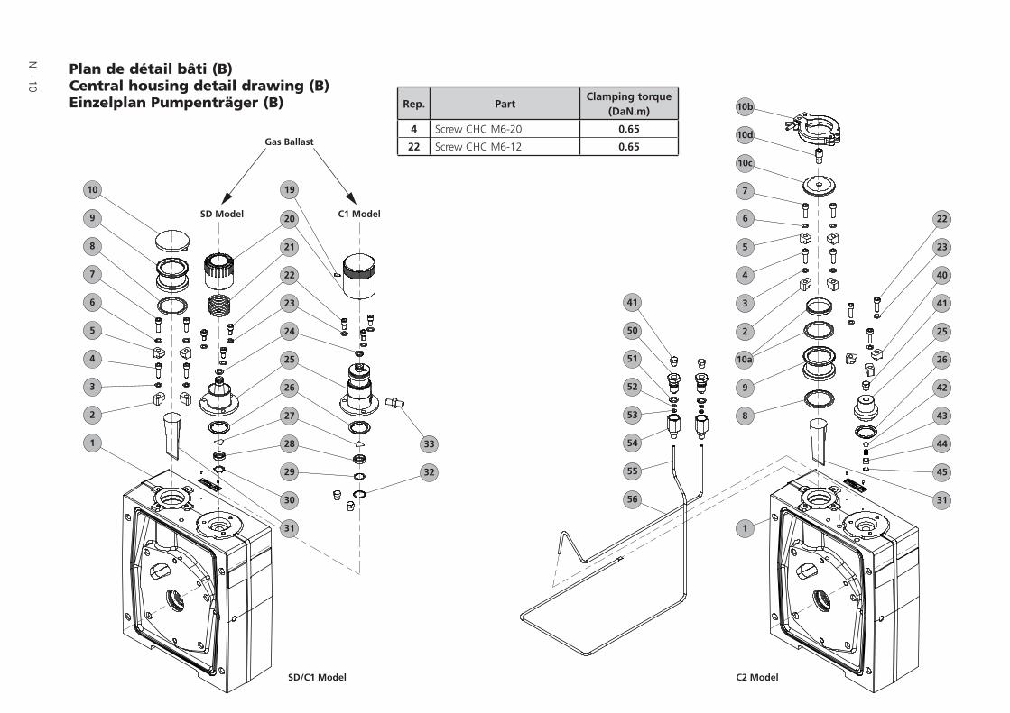
N – 10
Plan de détail bâti (B)Central housing detail drawing (B)Einzelplan Pumpenträger (B) Rep. Part
Clamping torque(DaN.m)
4 Screw CHC M6-20 0.65
22 Screw CHC M6-12 0.65
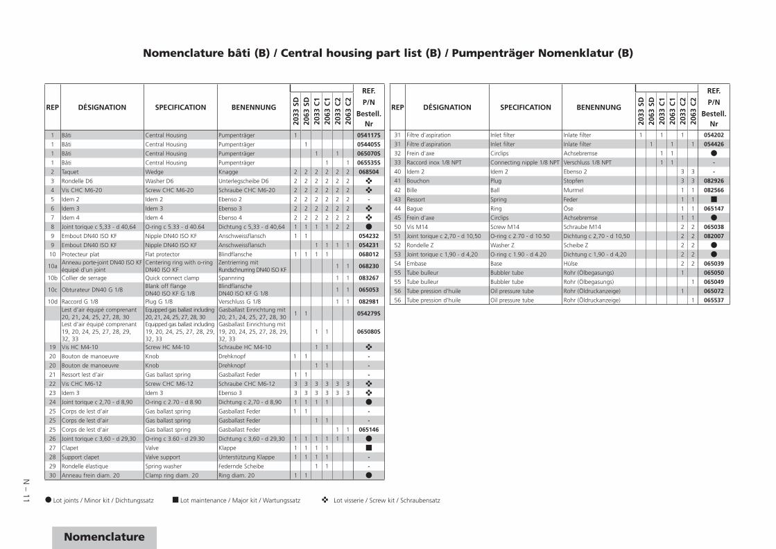
N – 11
Nomenclature
Nomenclature bâti (B) / Central housing part list (B) / Pumpenträger Nomenklatur (B)
REP DÉSIGNATION SPECIFICATION BENENNUNG
REF.
P/N
Bestell. Nr20
33 S
D20
63 S
D20
33 C
120
63 C
120
33 C
220
63 C
2
1 Bâti Central Housing Pumpenträger 1 054117S
1 Bâti Central Housing Pumpenträger 1 054405S
1 Bâti Central Housing Pumpenträger 1 1 065070S
1 Bâti Central Housing Pumpenträger 1 1 065535S
2 Taquet Wedge Knagge 2 2 2 2 2 2 068504
3 Rondelle D6 Washer D6 Unterlegscheibe D6 2 2 2 2 2 2
4 Vis CHC M6-20 Screw CHC M6-20 Schraube CHC M6-20 2 2 2 2 2 2
5 Idem 2 Idem 2 Ebenso 2 2 2 2 2 2 2 -
6 Idem 3 Idem 3 Ebenso 3 2 2 2 2 2 2
7 Idem 4 Idem 4 Ebenso 4 2 2 2 2 2 2
8 Joint torique c 5,33 - d 40,64 O-ring c 5.33 - d 40.64 Dichtung c 5,33 - d 40,64 1 1 1 1 2 2
9 Embout DN40 ISO KF Nipple DN40 ISO KF Anschweissflansch 1 1 054232
9 Embout DN40 ISO KF Nipple DN40 ISO KF Anschweissflansch 1 1 1 1 054231
10 Protecteur plat Flat protector Blindflansche 1 1 1 1 068012
10aAnneau porte-joint DN40 ISO KF équipé d’un joint
Centering ring with o-ring DN40 ISO KF
Zentrierring mit Rundschnurring DN40 ISO KF
1 1 068230
10b Collier de serrage Quick connect clamp Spannring 1 1 083267
10c Obturateur DN40 G 1/8Blank off flangeDN40 ISO KF G 1/8
BlindflanscheDN40 ISO KF G 1/8
1 1 065053
10d Raccord G 1/8 Plug G 1/8 Verschluss G 1/8 1 1 082981Lest d'air équipé comprenant 20, 21, 24, 25, 27, 28, 30
Equipped gas ballast including 20, 21, 24, 25, 27, 28, 30
Gasballast Einrichtung mit20, 21, 24, 25, 27, 28, 30
1 1 054279S
Lest d'air équipé comprenant 19, 20, 24, 25, 27, 28, 29, 32, 33
Equipped gas ballast including 19, 20, 24, 25, 27, 28, 29, 32, 33
Gasballast Einrichtung mit19, 20, 24, 25, 27, 28, 29, 32, 33
1 1 065080S
19 Vis HC M4-10 Screw HC M4-10 Schraube HC M4-10 1 1
20 Bouton de manoeuvre Knob Drehknopf 1 1 -
20 Bouton de manoeuvre Knob Drehknopf 1 1 -
21 Ressort lest d’air Gas ballast spring Gasballast Feder 1 1 -
22 Vis CHC M6-12 Screw CHC M6-12 Schraube CHC M6-12 3 3 3 3 3 3
23 Idem 3 Idem 3 Ebenso 3 3 3 3 3 3 3
24 Joint torique c 2,70 - d 8,90 O-ring c 2.70 - d 8.90 Dichtung c 2,70 - d 8,90 1 1 1 1
25 Corps de lest d’air Gas ballast spring Gasballast Feder 1 1 -
25 Corps de lest d’air Gas ballast spring Gasballast Feder 1 1 -
25 Corps de lest d’air Gas ballast spring Gasballast Feder 1 1 065146
26 Joint torique c 3,60 - d 29,30 O-ring c 3.60 - d 29.30 Dichtung c 3,60 - d 29,30 1 1 1 1 1 1
27 Clapet Valve Klappe 1 1 1 1
28 Support clapet Valve support Unterstützung Klappe 1 1 1 1 -
29 Rondelle élastique Spring washer Federnde Scheibe 1 1 -
30 Anneau frein diam. 20 Clamp ring diam. 20 Ring diam. 20 1 1
Lot joints / Minor kit / Dichtungssatz Lot maintenance / Major kit / Wartungssatz Lot visserie / Screw kit / Schraubensatz
REP DÉSIGNATION SPECIFICATION BENENNUNG
REF.
P/N
Bestell. Nr20
33 S
D20
63 S
D20
33 C
120
63 C
120
33 C
220
63 C
2
31 Filtre d'aspiration Inlet filter Inlate filter 1 1 1 054202
31 Filtre d'aspiration Inlet filter Inlate filter 1 1 1 054426
32 Frein d'axe Circlips Achsebremse 1 1
33 Raccord inox 1/8 NPT Connecting nipple 1/8 NPT Verschluss 1/8 NPT 1 1 -
40 Idem 2 Idem 2 Ebenso 2 3 3 -
41 Bouchon Plug Stopfen 3 3 082926
42 Bille Ball Murmel 1 1 082566
43 Ressort Spring Feder 1 1
44 Bague Ring Öse 1 1 065147
45 Frein d’axe Circlips Achsebremse 1 1
50 Vis M14 Screw M14 Schraube M14 2 2 065038
51 Joint torique c 2,70 - d 10,50 O-ring c 2.70 - d 10.50 Dichtung c 2,70 - d 10,50 2 2 082007
52 Rondelle Z Washer Z Scheibe Z 2 2
53 Joint torique c 1,90 - d 4,20 O-ring c 1.90 - d 4.20 Dichtung c 1,90 - d 4,20 2 2
54 Embase Base Hülse 2 2 065039
55 Tube bulleur Bubbler tube Rohr (Ölbegasungs) 1 065050
55 Tube bulleur Bubbler tube Rohr (Ölbegasungs) 1 065049
56 Tube pression d’huile Oil pressure tube Rohr (Öldruckanzeige) 1 065072
56 Tube pression d’huile Oil pressure tube Rohr (Öldruckanzeige) 1 065537
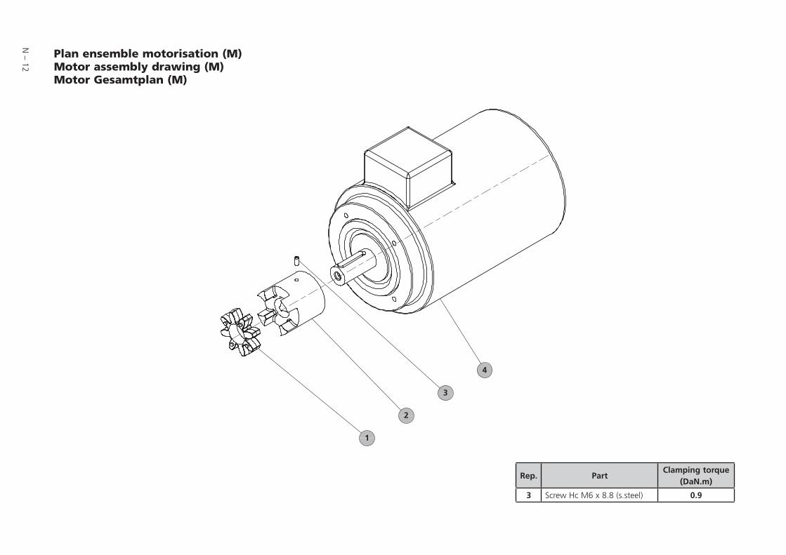
N – 12
Plan ensemble motorisation (M)Motor assembly drawing (M) Motor Gesamtplan (M)
Rep. PartClamping torque
(DaN.m)
3 Screw Hc M6 x 8.8 (s.steel) 0.9

N – 13
Nomenclature
Nomenclature ensemble motorisation (M) / Motor assembly part list (M) / Motor Nomenklatur (M)
REP DÉSIGNATION SPECIFICATION BENENNUNG
Types/modelREF.P/N
Bestell. Nr
2033
SD
2063
SD
2033
C1
2063
C1
2033
C2
2063
C2
1 Anneau élastique denté Elastic coupling Elastische Zahnscheibe 1 1 11 Anneau élastique denté Elastic coupling Elastische Zahnscheibe 1 1 12 Manchon moteur Motor coupling Motorkupplung 1 1 1 054116
2 Manchon moteur Motor coupling Motorkupplung 1 1 1 054436
3 Vis HC M6-12 Screw HC M6-12 Schraube HC M6-12 1 1 1 1 1 1
4 Moteur triphasé EUROPE 1.1/1.3 kW 190/480V - 50/60Hz - 1500/1800 tr/mn
Tree-phase motor EUROPE 1.1/1.3 kW190/480V - 50/60Hz - 1500/1800 tr/mn
Elektromotor 3 ph. EUROPA 1.1/1.3 kW190/480V - 50/60Hz - 1500/1800 tr/mn 1 1 1 119978
4 Moteur triphasé EUROPE 2.2/2.6 kW190/480V - 50/60Hz - 1500/1800 tr/mn
Tree-phase motor EUROPE 2.2/2.6 kW190/480V - 50/60Hz - 1500/1800 tr/mn
Elektromotor 3 ph. EUROPA 2.2/2.6 kW190/480V - 50/60Hz - 1500/1800 tr/mn 1 1 1 119979
4 Moteur triphasé USA/JAPAN 1.1/1.3 kW175/460V - 50/60Hz - 1500/1800 tr/mn
Tree-phase motor USA/JAPAN 1.1/1.3 kW175/460V - 50/60Hz - 1500/1800 tr/mn
Elektromotor 3 ph. USA/JAPAN 1.1/1.3 kW175/460V - 50/60Hz - 1500/1800 tr/mn 1 1 1 119977
4 Moteur triphasé USA/JAPAN 2.2/2.6 kW175/460V - 50/60Hz - 1500/1800 tr/mn
Tree-phase motor USA/JAPAN 2.2/2.6 kW175/460V - 50/60Hz - 1500/1800 tr/mn
Elektromotor 3 ph. USA/JAPAN 2.2/2.6 kW175/460V - 50/60Hz - 1500/1800 tr/mn 1 1 1 119980
4 Moteur triphasé ASIA/ROW 1.1/1.3 kW180/480V - 50/60Hz - 1500/1800 tr/mn
Tree-phase motor ASIA/ROW 1.1/1.3 kW180/480V - 50/60Hz - 1500/1800 tr/mn
Elektromotor 3 ph. ASIA/ROW 1.1/1.3 kW180/480V - 50/60Hz - 1500/1800 tr/mn 1 1 1 114449
4 Moteur triphasé ASIA/ROW 2.2/2.6 kW180/480V - 50/60Hz - 1500/1800 tr/mn
Tree-phase motor ASIA/ROW 2.2/2.6 kW180/480V - 50/60Hz - 1500/1800 tr/mn
Elektromotor 3 ph. ASIA/ROW 2.2/2.6 kW180/480V - 50/60Hz - 1500/1800 tr/mn 1 1 1 114450
Lot joints / Minor kit / Dichtungssatz Lot maintenance / Major kit / Wartungssatz Lot visserie / Screw kit / Schraubensatz
Pfeiffer Vacuum stands for innovative and custom vacuum Pfeiffer Vacuum stands for innovative and custom vacuum solutions worldwide. For German engineering art, competent solutions worldwide. For German engineering art, competent advice and reliable services.advice and reliable services.
Even since the invention of the turbopump, we’ve been setting Even since the invention of the turbopump, we’ve been setting standards in our industry. And this claim to leadership will continue standards in our industry. And this claim to leadership will continue to drive use in the future.to drive use in the future.
Leading. Dependable.Leading. Dependable.Customer Friendly.Customer Friendly.
You are looking for a You are looking for a perfect vacuum solution?perfect vacuum solution?Please contact us:Please contact us:
Pfeiffer Vacuum Products GmbHPfeiffer Vacuum Products GmbHBerliner Strasse 43Berliner Strasse 4335614 Asslar - Germany35614 Asslar - GermanyT +49 6441 802-0T +49 6441 802-0F +49 6441 802-202F +49 6441 [email protected]@pfeiffer-vacuum.dewww.pfeiffer-vacuum.dewww.pfeiffer-vacuum.de
adixen Vacuum Productsadixen Vacuum Products98 avenue de Brogny98 avenue de Brogny74009 Annecy Cedex - France74009 Annecy Cedex - FranceT +33 (0) 4 50 65 77 77T +33 (0) 4 50 65 77 77F +33 (0) 4 50 65 77 89F +33 (0) 4 50 65 77 [email protected]@adixen.frwww.adixen.comwww.adixen.com
Orig
inal
/ Tra
nsla
ted
from
orig
inal
ver
sionB
etrie
bBB
tibB
Ed
04-D
ate:
07/
12-P
/N:1
0552
7
E
d 04
-Dat
e: 0
7/12
-P/N
:105
527
*105527*
*105527*