Bolt Die Cutting threads on bolts and rods.. Bolt Die Stock Holder for bolt tie.

1©Copyright 2006, A & I EX-9554-012406
ENGINE OIL GRADE: AC-PH08: SAE 10W-30 AC-PI08: Above 40°F=SAE30 / Below 40°F-SAE10W-30 ENGINE OIL CAPACITY: 20oz. MAXIMUM PRESSURE 125 PSI COMPRESSOR OIL GRADE: SAE30W Non-Detergent COMPRESSOR OIL CAPACITY: 17.3 oz.
PARTS LIST FORAIR COMPRESSORS
AC-PH08AC-PI08
2©Copyright 2006, A & I EX-9554-012406
This Parts Listing has been compiled for your benefit. You can be assured your gasoline air compressor was constructed and designed with quality and performance in mind. Each component has been rigorously tested to insure the highest level of acceptance.
The contents of this Parts Listing are based on the latest product information available at the time of publication. The manufacturer reserves the right to make changes in price, color, materials, equipment, specifications or models at any time without notice.
WARNINGTHIS IS A PROFESSIONAL GASOLINE AIR COMPRESSOR. CAUTION SHOULD BE OBSERVED WHEN USING OR REPAIRING
THIS UNIT! READ AND FOLLOW THE SAFETY WARNINGS LISTED BELOW BEFORE ATTEMPTING ANY REPAIRS ON THIS GASOLINE AIR COMPRESSOR!
SAFETY WARNINGS1. NEVER alter or modify the equipment. Be sure any accessory items and system components being used will withstand the pressure developed. Serious injury may occur from an air compressor malfunction or exploding accessories if incorrect system components, attachments or accessories are used. NEVER exceed manufactures maximum allowable pressure rating of attachments. Use only genuine manufacturer parts for repair of your air compressor. Failure to do so can cause hazardous operating conditions and will VOID warranty.
2. NEVER make adjustments on machinery without first removing the ignition cable from the engine spark plug. Turning over the machinery by hand during adjustment or cleaning might start the engine, causing serious injury to the operator.
3. Know how to stop and bleed pressures quickly. Be thoroughly familiar with controls. Do not operate without protective covers/ guards.
4. Before servicing the unit, turn unit off, relieve the pressure and allow the unit to cool down. Service in a clean, dry, flat area. Block the wheels to prevent the unit from moving. Be especially careful to properly dispose of any flammable materials.
5. After testing the machine, DO NOT leave the pressurized unit unattended. Shut off the unit and release pressure before leaving.
Table of Contents
SPECIFICATIONS ...........................................................................................................................................................................................................3FLOW CHART ................................................................................................................................................................................................................4GENERAL THEORY OF OPERATION ...........................................................................................................................................................................5TANK ASSEMBLY FOR AC-PH08 .................................................................................................................................................................................6TANK ASSEMBLY FOR AC-PI08 ...................................................................................................................................................................................8SINGLE STAGE COMPRESSOR (3-0215) ....................................................................................................................................................................10PILOT VALVE ADJUSTMENT (GASOLINE) ..................................................................................................................................................................12NOTES ............................................................................................................................................................................................................................13
3©Copyright 2006, A & I EX-9554-012406
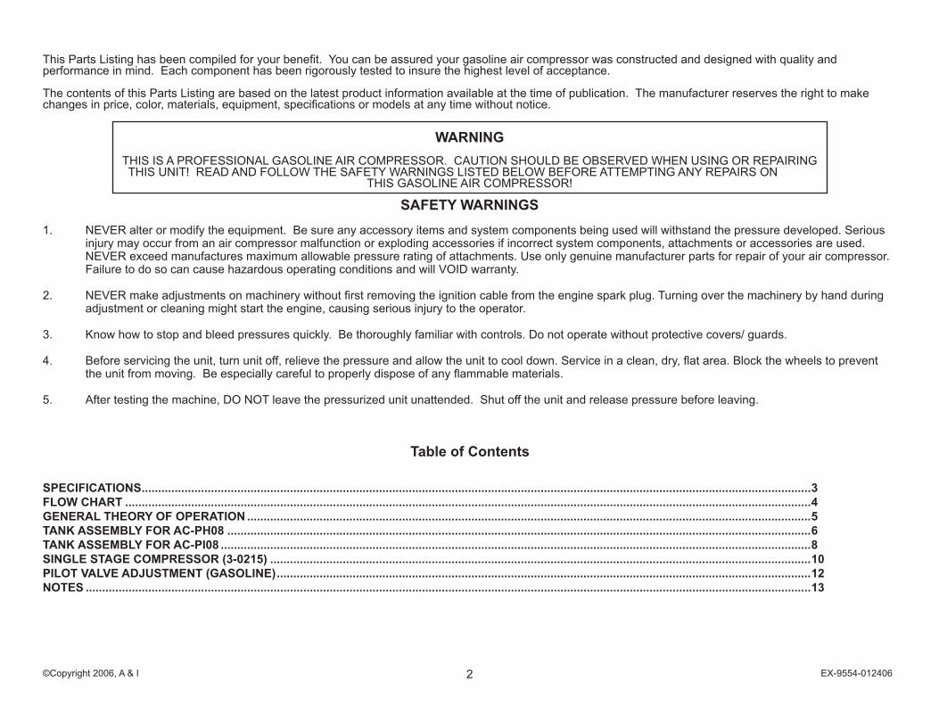
SPECIFICATIONSMODEL NUMBER AC-PH08 AC-PI08
Engine: Honda Briggs Intek I/C Horsepower 5.5 6.5 Engine Type 4 Stroke, Overhead Valve, Single Cylinder Oil Type SAE 10W 30 Above 40°F=SAE30/Below 40°F=SAE10W-30 Oil Capacity (oz./liters) 20/.6 Low Oil Protection Oil Alert™ Oil Guard ™ Fuel Type Unleaded Gasoline 86 Octane Minimum Fuel Capacity (gallon/liters) .95/3.6 Starting Recoil Engine RPM 3200 Idle RPM 2200-2400 Compressor Pump: Number of Cylinders 2 Compression Stages 1 Bore/Stroke 2.5" x 1.88" RPM 1380 Flywheel 10" Lubrication Splash Oil Quantity 17.3 oz. Oil Type 30 W Non Detergent Crankcase Cast Iron Bearings Ball Cylinder Cast Iron Valves Reed-Single Head Cast Iron Filter Canister Pilot Valve Setting: Cut-out 125 PSI Cut-in 95 PSI Air Tank: Capacity 8 Gallons Performance: CFM Air Displacement 14.7 CFM @ 40 PSI 10.6 CFM @ 100 PSI 9.0 Maximum Pressure 125 PSI Pump-up Time: 0-125 PSI 54 seconds Recovery Time: 95-125 PSI 14 seconds Weight: Net 171 lbs Shipping 197 lbs Dimensions: Basic L x W x H 44.5" x 18.5" x 26" Shipping L x W x H 45" x 19" x 32"

4©Copyright 2006, A & I EX-9554-012406
OM
AC
0048
-102
798-
RD
FLOW CHART
1212
1311
8
435
1
14
1615
1718
1921
23
22 24 25
26
7
20
2
139
6
10

5©Copyright 2006, A & I EX-9554-012406
1. The ENGINE (1) supplies power to the air compressor. a. The ENGINE (1) is lubricated by oil. The oil level should be checked before each use by removing the ENGINE OIL DIPSTICK (2 ). b. The ENGINE (1) runs on gasoline. The FUEL TANK (3) level should be checked before each use. c. The ENGINE ON/OFF SWITCH (4) and STARTER ROPE (5) are used to start the engine. d. Refer to engine owner’s manual for appropriate starting procedures and requirements of the ENGINE (1).
2. The COMPRESSOR PUMP (6) is lubricated by oil. The oil level should be checked before each use by removing the COMPRESSOR PUMP OIL DIPSTICK (7). Fill to proper level with SAE-30W non-detergent oil if needed.
3. When the unit is operating, the V-BELT (8) turns the COMPRESSOR PUMP FLYWHEEL (9) which rotates the crankshaft and moves the PISTONS (10).
4 As the PISTON (10) moves down, air is drawn in through the INLET AIR FILTER (11) and then through the INLET REED VALVE (12). At the same time, the OUTLET REED VALVE (13) is closed. This allows air to fill the piston chamber.
5. As the PISTON (10) moves up, the INLET REED VALVE (12) closes and the OUTLET REED VALVE (13) opens allowing the compressed air to flow into the PUMP DISCHARGE LINE (14).
6. The compressed air then enters the PILOT CONTROL VALVE (15) which has an TOGGLE KNOB (16) with two positions. a. Easy Start Position: When the TOGGLE KNOB (16) is in the open position (vertical) air moves out the PILOT VALVE MUFFLER (17) allowing the ENGINE (1) to start under no-load conditions . b. Constant Run Position: When the TOGGLE KNOB (16) is in the closed position (horizontal) the compressed air opens the CHECK VALVE (18) and moves into the AIR TANK (19). When the pressure in the AIR TANK (19) reaches the maximum pressure setting of the PILOT CONTROL VALVE (15), the excess air exits the PILOT VALVE MUFFLER (17) and the CHECK VALVE (18) will close. At the same time the THROTTLE CONTROL (20) allows the ENGINE (1) to idle down.
7. The SAFETY RELIEF VALVE (21) protects the system from any overpressure conditions.
8. The TANK PRESSURE GAUGE (22) indicates tank pressure. The AIR PRESSURE REGULATOR (23) can be adjusted to the desired operating pressure which is indicated on the OUTLET PRESSURE GAUGE (24). The air exits through the OUTLET FITTING (25).
9. The ENGINE ON/OFF SWITCH (4) stops the ENGINE (1) when moved to the “OFF” position.
10. When the ENGINE (1) is off, compressed air should be released from the AIR TANK (19) by opening the attached air tool or by pulling on the SAFETY RELIEF VALVE (21). When the TANK PRESSURE GAUGE (22) registers less than 10 PSI, drain the condensation from the AIR TANK (19) by opening the TANK DRAIN (26).
GENERAL THEORY OF OPERATION

6©Copyright 2006, A & I EX-9554-012406
TANK ASSEMBLY FOR AC-PH08A
C1-
PH
55-0
8AI-0
1160
6-JJ
T

7©Copyright 2006, A & I EX-9554-012406
AC1-PH55-08AI-011606-JJT
TANK ASSEMBLY FOR AC-PH08
REF # DESCRIPTION PART # QTY REF # DESCRIPTION PART # QTY REF # DESCRIPTION PART # QTY
1 Decal-Maintenance Instructions (See 34-9016) N/A Sep. 1 29 Regulator Plug 24-0082 1 57 Decal- Warning: Beltguard in Place (See 34-9016) N/A Sep. 1
2 Bolt 27-0576 1 30 Regulator-Adjustable 22-0231 1 58 Beltguard Back (See 854-0007) N/A Sep. 1
3 Flatwasher 28-0023 1 31 Hose Barb 23-0105 1 59 Key 43-0073 1
4 Belt Tensioner Plate 20-0614A01 1 32 Hose *(One Foot Required) 15-0007 1 60 Decal- Check Oil Tape (See 34-9016) N/A Sep. 2
5 Air Tank Assembly (Inc. 12, 13, 18) 854-0027 1 33 Tee 23-0127 1 61 Engine- 5.5 HP Honda 1-0013 1
6 Cotter Pin 43-0092 2 34 Reducer 23-0111 1 62 Decal- Warning: Muffler Hot (See 34-9016) N/A Sep. 1
7 Axle 20-0420 1 35 Safety Valve 22-0228 1 63 Decal- Caution: Allow to Cool (See 34-9016) N/A Sep. 1
8 Washer 28-0008 8 36 Bolt 27-0068 4 64 Bolt 27-0074 2
9 Wheel 14-0017 1 37 Washer 28-0022 8 65 Bolt 27-0070 4
10 Decal- Data Plate N/A 1 38 Air Filter Assembly (Inc.. 39-41) 19-0083 1 66 Spacer 33-0358 2
11 Decal- Logo 34-1781 1 39 Front Filter Housing 19-0084 1 67 Elbow 23-0426 1
12 Decal- Warning: Hot Surface (See 34-9016) N/A Sep. 1 40 Filter Replacement 19-0082 1 68 Pump 3-0215 1
13 Decal- Danger/Warning/Caution (See 34-9016) N/A Sep. 1 41 Rear Filter Housing (See 19-0083) N/A Sep. 1 69 Hose 15-0235 1
14 Washer 28-0002 14 42 Air Shroud 20-0612A01 1 70 Pilot Valve 22-0346 1
15 Bolt 27-0015 13 43 Gasket *(One Foot Required) 26-0240 1 71 Air Throttle Control Assembly (Inc. 72-81) 854-0064 1
16 Isolator 14-0069 4 44 Flywheel w/ Compressor 10-0115 1 72 Clamp Screw (See 854-0064) N/A Sep. 1
17 Locknut 30-0155 7 45 Drive Belt 11-0011 1 73 Throttle Clamp (See 854-0064) N/A Sep. 1
18 Decal- Drain Tank (See 34-9016) N/A Sep. 2 46 Flatwasher Flywheel w/ Compressor 28-1032 1 74 Engine Throttle Clip 45-0084 1
19 Drain Valve 23-0312 2 47 Decal- Operating Instructions (See 34-9016) N/A Sep. 1 75 Throttle Control Adapter 62-0126 1
20 Handle Grips 7-0143 2 48 Fastener 33-0197 1 76 Air Throttle Control 33-0394 1
21 Elbow 23-0418 1 49 Beltguard Assembly (Inc. 50-51) 854-0009 1 77 Air Throttle Control Clip N/A Sep. 1
22 Hose Clamp 42-0011 2 50 Beltguard Cover (See 854-0009) N/A Sep. 1 78 Plastic Tube Support Insert 23-0425 2
23 Pressure Gauge 22-0257 2 51 Edging *(Four Feet Required) 33-0020 1 79 Nut 23-0315 1
24 Nipple 24-0010 1 52 Bolt w/Bushing 27-0015 2 80 Tube *(Two Feet Required) 15-0238 1
25 Locknut 30-0157 10 53 Bushing 9-0009 1 81 Fitting 23-0328 1
26 Washer 28-0003 14 54 Drive Pulley 10-0101 1 Safety Decal Kit (Inc. 1, 12-13, 47, 57, 60, 62-63) 34-9016 1
27 Regulator Mounting Bracket 20-0421A01 1 55 Beltguard Back Assembly (Inc. 56-58) 854-0007 1 *Must Order in One Foot Lengths
28 Bolt 27-0067 3 56 Edging *(Two Feet Required) 33-0020 1

8©Copyright 2006, A & I EX-9554-012406
TANK ASSEMBLY FOR AC-PI08A
C1-
PI6
5-08
AI-0
1160
6-JJ
T
9©Copyright 2006, A & I EX-9554-012406
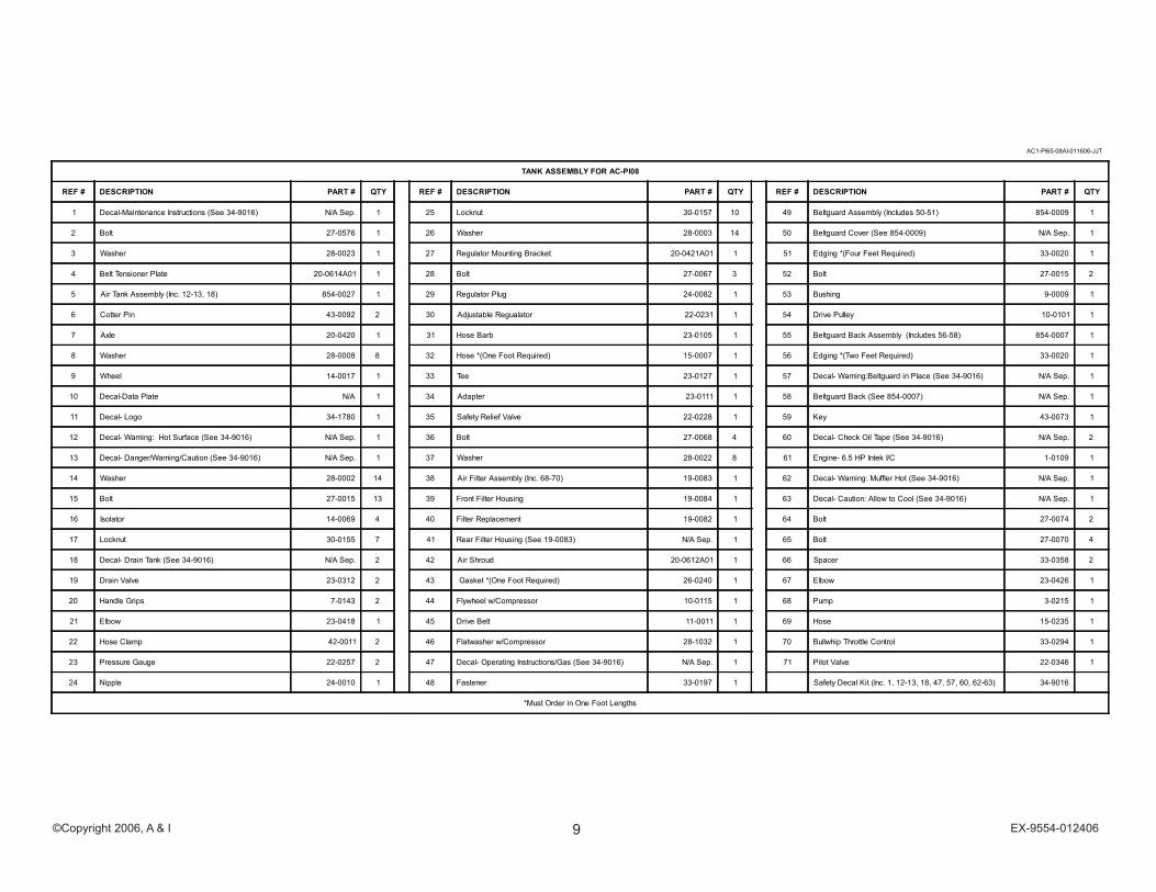
AC1-PI65-08AI-011606-JJT
TANK ASSEMBLY FOR AC-PI08
REF # DESCRIPTION PART # QTY REF # DESCRIPTION PART # QTY REF # DESCRIPTION PART # QTY
1 Decal-Maintenance Instructions (See 34-9016) N/A Sep. 1 25 Locknut 30-0157 10 49 Beltguard Assembly (Includes 50-51) 854-0009 1
2 Bolt 27-0576 1 26 Washer 28-0003 14 50 Beltguard Cover (See 854-0009) N/A Sep. 1
3 Washer 28-0023 1 27 Regulator Mounting Bracket 20-0421A01 1 51 Edging *(Four Feet Required) 33-0020 1
4 Belt Tensioner Plate 20-0614A01 1 28 Bolt 27-0067 3 52 Bolt 27-0015 2
5 Air Tank Assembly (Inc. 12-13, 18) 854-0027 1 29 Regulator Plug 24-0082 1 53 Bushing 9-0009 1
6 Cotter Pin 43-0092 2 30 Adjustable Regualator 22-0231 1 54 Drive Pulley 10-0101 1
7 Axle 20-0420 1 31 Hose Barb 23-0105 1 55 Beltguard Back Assembly (Includes 56-58) 854-0007 1
8 Washer 28-0008 8 32 Hose *(One Foot Required) 15-0007 1 56 Edging *(Two Feet Required) 33-0020 1
9 Wheel 14-0017 1 33 Tee 23-0127 1 57 Decal- Warning:Beltguard in Place (See 34-9016) N/A Sep. 1
10 Decal-Data Plate N/A 1 34 Adapter 23-0111 1 58 Beltguard Back (See 854-0007) N/A Sep. 1
11 Decal- Logo 34-1780 1 35 Safety Relief Valve 22-0228 1 59 Key 43-0073 1
12 Decal- Warning: Hot Surface (See 34-9016) N/A Sep. 1 36 Bolt 27-0068 4 60 Decal- Check Oil Tape (See 34-9016) N/A Sep. 2
13 Decal- Danger/Warning/Caution (See 34-9016) N/A Sep. 1 37 Washer 28-0022 8 61 Engine- 6.5 HP Intek I/C 1-0109 1
14 Washer 28-0002 14 38 Air Filter Assembly (Inc. 68-70) 19-0083 1 62 Decal- Warning: Muffler Hot (See 34-9016) N/A Sep. 1
15 Bolt 27-0015 13 39 Front Filter Housing 19-0084 1 63 Decal- Caution: Allow to Cool (See 34-9016) N/A Sep. 1
16 Isolator 14-0069 4 40 Filter Replacement 19-0082 1 64 Bolt 27-0074 2
17 Locknut 30-0155 7 41 Rear Filter Housing (See 19-0083) N/A Sep. 1 65 Bolt 27-0070 4
18 Decal- Drain Tank (See 34-9016) N/A Sep. 2 42 Air Shroud 20-0612A01 1 66 Spacer 33-0358 2
19 Drain Valve 23-0312 2 43 Gasket *(One Foot Required) 26-0240 1 67 Elbow 23-0426 1
20 Handle Grips 7-0143 2 44 Flywheel w/Compressor 10-0115 1 68 Pump 3-0215 1
21 Elbow 23-0418 1 45 Drive Belt 11-0011 1 69 Hose 15-0235 1
22 Hose Clamp 42-0011 2 46 Flatwasher w/Compressor 28-1032 1 70 Bullwhip Throttle Control 33-0294 1
23 Pressure Gauge 22-0257 2 47 Decal- Operating Instructions/Gas (See 34-9016) N/A Sep. 1 71 Pilot Valve 22-0346 1
24 Nipple 24-0010 1 48 Fastener 33-0197 1 Safety Decal Kit (Inc. 1, 12-13, 18, 47, 57, 60, 62-63) 34-9016
*Must Order in One Foot Lengths

10©Copyright 2006, A & I EX-9554-012406
SINGLE STAGE COMPRESSOR (3-0215)3-
0215
-032
905-
JJF
11©Copyright 2006, A & I EX-9554-012406
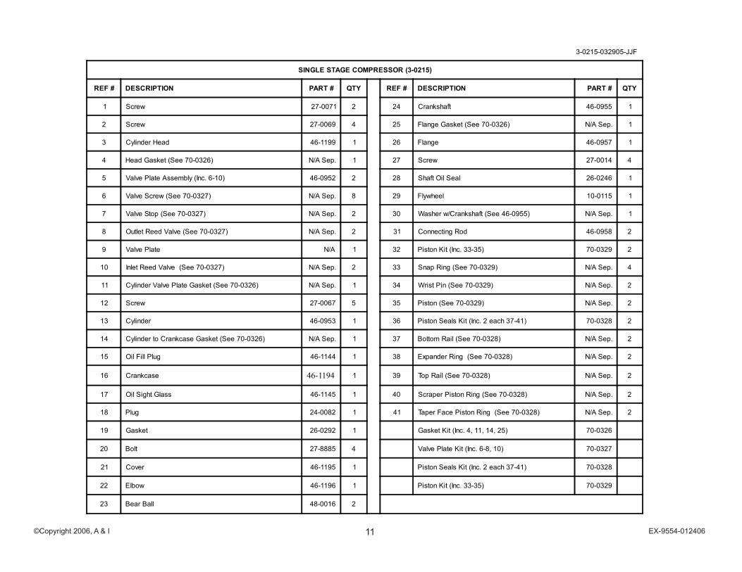
3-0215-032905-JJF
SINGLE STAGE COMPRESSOR (3-0215)
REF # DESCRIPTION PART # QTY REF # DESCRIPTION PART # QTY
1 Screw 27-0071 2 24 Crankshaft 46-0955 1
2 Screw 27-0069 4 25 Flange Gasket (See 70-0326) N/A Sep. 1
3 Cylinder Head 46-1199 1 26 Flange 46-0957 1
4 Head Gasket (See 70-0326) N/A Sep. 1 27 Screw 27-0014 4
5 Valve Plate Assembly (Inc. 6-10) 46-0952 2 28 Shaft Oil Seal 26-0246 1
6 Valve Screw (See 70-0327) N/A Sep. 8 29 Flywheel 10-0115 1
7 Valve Stop (See 70-0327) N/A Sep. 2 30 Washer w/Crankshaft (See 46-0955) N/A Sep. 1
8 Outlet Reed Valve (See 70-0327) N/A Sep. 2 31 Connecting Rod 46-0958 2
9 Valve Plate N/A 1 32 Piston Kit (Inc. 33-35) 70-0329 2
10 Inlet Reed Valve (See 70-0327) N/A Sep. 2 33 Snap Ring (See 70-0329) N/A Sep. 4
11 Cylinder Valve Plate Gasket (See 70-0326) N/A Sep. 1 34 Wrist Pin (See 70-0329) N/A Sep. 2
12 Screw 27-0067 5 35 Piston (See 70-0329) N/A Sep. 2
13 Cylinder 46-0953 1 36 Piston Seals Kit (Inc. 2 each 37-41) 70-0328 2
14 Cylinder to Crankcase Gasket (See 70-0326) N/A Sep. 1 37 Bottom Rail (See 70-0328) N/A Sep. 2
15 Oil Fill Plug 46-1144 1 38 Expander Ring (See 70-0328) N/A Sep. 2
16 Crankcase 46-1194 1 39 Top Rail (See 70-0328) N/A Sep. 2
17 Oil Sight Glass 46-1145 1 40 Scraper Piston Ring (See 70-0328) N/A Sep. 2
18 Plug 24-0082 1 41 Taper Face Piston Ring (See 70-0328) N/A Sep. 2
19 Gasket 26-0292 1 Gasket Kit (Inc. 4, 11, 14, 25) 70-0326
20 Bolt 27-8885 4 Valve Plate Kit (Inc. 6-8, 10) 70-0327
21 Cover 46-1195 1 Piston Seals Kit (Inc. 2 each 37-41) 70-0328
22 Elbow 46-1196 1 Piston Kit (Inc. 33-35) 70-0329
23 Bear Ball 48-0016 2
12©Copyright 2006, A & I EX-9554-012406
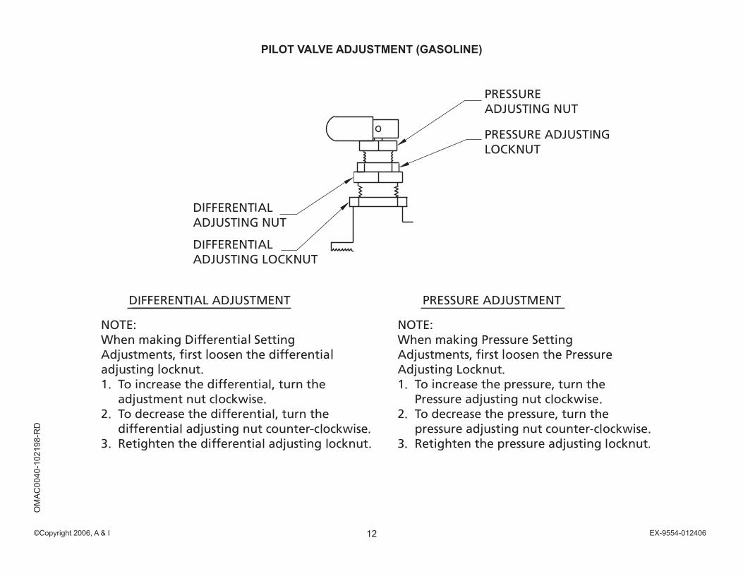
PILOT VALVE ADJUSTMENT (GASOLINE)O
MA
C00
40-1
0219
8-R
D

13©Copyright 2006, A & I EX-9554-012406
NOTES

14©Copyright 2006, A & I EX-9554-012406
NOTES

15©Copyright 2006, A & I EX-9554-012406
NOTES

16©Copyright 2006, A & I EX-9554-012406