PartPart 3 Works on Roads - Seton · PDF fileManual of Uniform Traffic Control Devices...
149
Manual of Uniform Traffic Control Devices Part Part 3 Works on Roads 2003 Edition First Issue 1st August, 2003 Second Issue 2nd April, 2007 Third Issue 22nd February, 2010 (electronic copy only) Fourth Issue 30th April, 2010 Fifth Issue 30th September, 2013 Sixth Issue 14th March, 2014 Sixth Issue (including Amdt. 1), 5th May 2014 Note:- This is a lower resolution file intended for screen viewing only. This file may not be suitable for printing. This file may be one part of a complete technical publication and should not be read in isoloationof the other parts of the publication. A full resolution version of all parts can be obtained from the Department of Transport and Main Roads web site (www.tmr.qld.gov.au) The Department of Transport and Main Roads takes no responsibility for any loss or damage resulting from the use of this lower resolution file.
Transcript of PartPart 3 Works on Roads - Seton · PDF fileManual of Uniform Traffic Control Devices...

Manual of Uniform Traffic Control Devices
PartPart 3Works onRoads
2003 EditionFirst Issue 1st August, 2003Second Issue 2nd April, 2007Third Issue 22nd February, 2010 (electronic copy only) Fourth Issue 30th April, 2010Fifth Issue 30th September, 2013Sixth Issue 14th March, 2014 Sixth Issue (including Amdt. 1), 5th May 2014
Not
e:- T
his
is a
low
er re
solu
tion
file
inte
nded
for s
cree
n vi
ewin
g on
ly. T
his
file
may
not
be
suita
ble
for p
rintin
g.
This
file
may
be
one
part
of a
com
plet
e te
chni
cal p
ublic
atio
n an
d sh
ould
not
be
read
in is
oloa
tiono
f the
oth
er p
arts
of t
he p
ublic
atio
n.
A fu
ll re
solu
tion
vers
ion
of a
ll pa
rts c
an b
e ob
tain
ed fr
om th
e D
epar
tmen
t of T
rans
port
and
Mai
n R
oads
web
site
(ww
w.tm
r.qld
.gov
.au)
Th
e D
epar
tmen
t of T
rans
port
and
Mai
n R
oads
take
s no
resp
onsi
bilit
y fo
r any
loss
or d
amag
e re
sulti
ng fr
om th
e us
e of
this
low
er re
solu
tion
file.

Copyright
http://creativecommons.org/licenses/by/3.0/au/
© State of Queensland (Department of Transport and Main Roads) 2014
Feedback: Please send your feedback regarding this document to: [email protected]
Manual of Uniform Traffic Control Devices, Transport and Main Roads, March 2014
3-2 3/2014
AmendmentsAmendment 1. Clause 4.10.2 Page 3-95

3-33/2014
PREFACE
This Part of the Manual of Uniform Traffic Control Devices (Queensland) has been based on AustralianStandard AS1742.3 - 2009, Traffic control for works on roads.
It updates the specification of traffic control devices for roadworks previously given in 2003 Manual ofUniform Traffic Control Devices and Departmental document Works on Roads. It deals with theprinciples of signing at roadworks, describes the signs and devices used to effect traffic guidance andprovides typical layout diagrams for deployment of signs and devices for various work siteconfigurations. It is intended as both an office reference document for the planning and design oftraffic guidance schemes, and a field guide for the installation, operation and removal of trafficguidance schemes.
This document should now be used for all roadworks. However, this document shall be used for allroadworks after 1st July 2014.
Principal variations from the previous issue are as follows:
Sixth Issue
1. Clarification of RPEQ certification in Clause 2.2.3 and new Clause 2.2.5.
2. Inclusion of new Table 3.7 for cones and bollard spacing to align with Australian StandardAS1742.3.
3. New Clause 3.16.10 Changed Traffic Conditions Ahead.
4. Align Clause 4.6.1 with AS1742.3.
5. Align Clause 4.8.2 to AS1742.3 regarding left hand merge when work being undertaken on insidelane on multi-lane roads.
6. Align Clause 4.8.3 to AS1742.3 regarding cone and bollard spacing.
7. Rearrangement of Table 4.7 to distinguish between worker safety and traffic safety.
8. Repeater speed sign requirements in Clause 4.9.8.
9. Additional explanation about example diagrams to Clause 5.5.1.
10. Addition of new Diagram 7D showing traffic management treatment to effect a right hand merge.
11. Amend example diagrams to indicate the placement of 4 cones on centreline of road in advance ofthe traffic control station to align with the requirements of new Table 3.7.
12. Requirement for safety garment in Table C1 for all personnel.
13. Clause E1 in Appendix E now applies to longitudinal excavations only. New Clause E4 to addresstransverse excavations.
14. Addition of new TC signs for on ramp merges and trenching works.
15. Rearrangement of Appendix J for Traffic Controllers.
16. New Appendix K for Traffic Management.
17. New Appendix L - Quick reference guides for alternative placement of signs at roadworks.
Version History: 2003 EditionFirst Issue 1st August, 2003Second Issue 2nd April, 2007Third Issue 22nd February, 2010 (electronic copy only) Fourth Issue 30th April, 2010Fifth Issue 30th September, 2013Sixth Issue 14th March, 2014Sixth Issue (including Amdt.1), 5th May 2014

3-4 3/2014

3-53/2014

(Blank)
3-6 3/2014

CONTENTS
SECTION 1. SCOPE AND GENERAL...........................................................................................3-131.1 SCOPE .....................................................................................................................................3-131.2 OBJECTIVE AND PRINCIPLES................................................................................................3-13
1.2.1 Objective ...................................................................................................................3-131.2.2 Principles ...................................................................................................................3-131.2.3 Innovation ..................................................................................................................3-13
1.3 REFERENCED DOCUMENTS ................................................................................................3-141.4 DEFINITIONS ...........................................................................................................................3-141.5 RESPONSIBILITY FOR SAFETY AT WORK SITES..................................................................3-161.6 LEGAL AUTHORITY .................................................................................................................3-171.7 LEVELS OF TRAINING.............................................................................................................3-171.8 TRAFFIC AND ROAD USE MANAGEMENT MANUAL.............................................................3-17
SECTION 2. PRINCIPLES FOR THE DEVELOPMENT, INSTALLATION AND OPERATION OF A TRAFFIC GUIDANCE SCHEME.....................................................................3-18
2.1 PRINCIPLES.............................................................................................................................3-182.2 PLANNING ...............................................................................................................................3-18
2.2.1 Traffic management planning process......................................................................3-182.2.2 Traffic management plans.........................................................................................3-182.2.3 Risk management......................................................................................................3-192.2.4 Traffic guidance schemes .........................................................................................3-192.2.5 Variation to optimal treatments and RPEQ certification............................................3-20
2.3 TRAFFIC MANAGEMENT ........................................................................................................3-212.3.1 General ......................................................................................................................3-212.3.2 Safety and convenience............................................................................................3-212.3.3 Traffic through the work area ....................................................................................3-212.3.4 Traffic past the work area ..........................................................................................3-222.3.5 Traffic around the work area (side-tracks and detours)............................................3-222.3.6 Night conditions ........................................................................................................3-222.3.7 Provision for pedestrians and bicycles .....................................................................3-232.3.8 Temporary footpaths and pedestrian crossing .........................................................3-23
2.4 DEVICE REQUIREMENTS .......................................................................................................3-232.4.1 Selection and use......................................................................................................3-232.4.2 Delineation.................................................................................................................3-242.4.3 Night conditions ........................................................................................................3-242.4.4 Adjustment to existing devices .................................................................................3-242.4.5 Safety barriers ...........................................................................................................3-242.4.6 Vehicle size and load restrictions..............................................................................3-25
2.5 INSTALLATION AND REMOVAL ..............................................................................................3-252.5.1 Condition of devices..................................................................................................3-252.5.2 Positioning of devices ...............................................................................................3-252.5.3 Setting out and recovery of devices .........................................................................3-262.5.4 Orientation of sign .....................................................................................................3-262.5.5 Inspection ..................................................................................................................3-262.5.6 Publicity .....................................................................................................................3-272.5.7 Removal.....................................................................................................................3-27
2.6 OPERATION.............................................................................................................................3-272.6.1 Daily routine and worksite records ...........................................................................3-272.6.2 Layout variation .........................................................................................................3-27
3-73/2014

2.6.3 Maintenance of devices.............................................................................................3-272.6.4 Use of high visibility clothing.....................................................................................3-272.6.5 Hazard avoidance .....................................................................................................3-272.6.6 Closures and delays..................................................................................................3-272.6.7 Safety audit................................................................................................................3-28
2.7 EMERGENCY AND UNPLANNED WORKS .............................................................................3-28
SECTION 3. DESCRIPTION AND USE OF SIGNS AND DEVICES..............................................3-293.1 FUNCTIONS OF DEVICES ......................................................................................................3-293.2 FORMAT AND SIZE OF SIGNS ...............................................................................................3-29
3.2.1 Format of signs..........................................................................................................3-293.2.2 Retroreflective material..............................................................................................3-293.2.3 Sign sizes in the T Series ..........................................................................................3-29
3.3 SIGN MOUNTINGS..................................................................................................................3-303.3.1 General ......................................................................................................................3-303.3.2 Multiple sign displays ................................................................................................3-303.3.3 Multiple-message sign displays................................................................................3-30
3.4 SIGNS AND DEVICES FOR WORK SITE APPROACHES AND DEPARTURES ......................3-313.4.1 General ......................................................................................................................3-313.4.2 Roadwork ahead (T1-1, T1-31), Roadwork X km ahead (T1-16),
Roadwork 500 m ahead (T1-16-Q01) .......................................................................3-313.4.3 Bridgework ahead (T1-2), Bridgework X km ahead (T1-29).....................................3-323.4.4 Workers (symbolic) (T1-5).........................................................................................3-323.4.5 Road plant ahead (T1-3), Grader ahead (T1-4) ........................................................3-323.4.6 Roadwork next X km (T1-24), Roadwork on side road (T1-25),
Road plant on side road (T1-27), Side road closed (T1-32).....................................3-333.4.7 Next 2 km (T1-28) and Next X km (T1-Q03)..............................................................3-333.4.8 End roadwork (T2-16, T2-17, T2-Q03) ......................................................................3-33
3.5 SIGNS AND DEVICES FOR REGULATORY CONTROL OF TRAFFIC ....................................3-343.5.1 General ......................................................................................................................3-343.5.2 Manual control...........................................................................................................3-353.5.3 Sign control ...............................................................................................................3-353.5.4 Traffic signal control ..................................................................................................3-363.5.5 Temporary speed limits .............................................................................................3-37
3.6 DETOUR SIGNS.......................................................................................................................3-383.6.1 General ......................................................................................................................3-383.6.2 Detour ahead (T1-6) ..................................................................................................3-393.6.3 End detour (T2-23) ....................................................................................................3-393.6.4 Detour (left or right) (T5-1) ........................................................................................3-393.6.5 Detour marker (T5-6) .................................................................................................3-393.6.6 Low bridge ahead ... m, High vehicles detour (G9-3),
Load limit on bridge ... t gross, Heavy vehicles detour (G9-4) .................................3-403.6.7 Detour for ... vehicles (G9-5) .....................................................................................3-403.6.8 Two-way traffic (W4-11)Two-way traffic (T2-24) ........................................................3-403.6.9 All traffic turn (R2-14).................................................................................................3-413.6.10 Local traffic only (G9-40-2) ........................................................................................3-41
3.7 ROAD CONDITION SIGNS ......................................................................................................3-413.7.1 General ......................................................................................................................3-413.7.2 Slippery (T3-3), Soft edges (T3-6), Rough surface (T3-7), Gravel road (T3-13),
Loose stones (T3-9), Loose surface (T3-14) .............................................................3-423.7.3 Advisory Speed signs (T3-16) ...................................................................................3-42
3-8 3/2014

3.7.4 New work, no lines marked (T3-11)No lines do not overtake unless safe (T3-12) ...........................................................3-43
3.8 SIGNS AND DEVICES FOR LANE AND ROAD CLOSURES...................................................3-433.8.1 General ......................................................................................................................3-433.8.2 Signs..........................................................................................................................3-433.8.3 Barricades..................................................................................................................3-44
3.9 DEVICES FOR DELINEATING AND INDICATING THE TRAVELLED PATH ............................3-453.9.1 Traffic cones and temporary bollards .......................................................................3-453.9.2 Roadworks delineators..............................................................................................3-463.9.3 Temporary hazard markers (T5-4, T5-5, T5-Q02) .....................................................3-483.9.4 Pavement markings...................................................................................................3-483.9.5 Raised retroreflective pavement markers .................................................................3-493.9.6 Temporary kerbing ....................................................................................................3-49
3.10 CONTAINMENT FENCES AND ROAD SAFETY BARRIER SYSTEMS...................................3-493.10.1 Containment fences ..................................................................................................3-493.10.2 Longitudinal channelising barricades .......................................................................3-493.10.3 Road safety barrier systems......................................................................................3-503.10.4 Temporary crash attenuators ....................................................................................3-50
3.11 LAMPS......................................................................................................................................3-513.12 VEHICLE-MOUNTED SIGNS AND DEVICES ..........................................................................3-51
3.12.1 Vehicle-mounted warning device ..............................................................................3-513.12.2 Illuminated flashing arrow sign .................................................................................3-513.12.3 Supplementary vehicle-mounted signs ....................................................................3-523.12.4 Painting of vehicles and machinery ..........................................................................3-533.12.5 Truck-mounted crash attenuator ...............................................................................3-53
3.13 BLASTING WORK SIGNS ........................................................................................................3-533.13.1 General ......................................................................................................................3-533.13.2 Blasting area switch off radio transmitters (T4-7) .....................................................3-543.13.3 End blasting area (T4-3)............................................................................................3-54
3.14 SIGNS AND DEVICES FOR PEDESTRIAN CONTROL ...........................................................3-543.14.1 General ......................................................................................................................3-543.14.2 Pedestrians watch your step (T8-1) ..........................................................................3-543.14.3 Pedestrians (arrow) (T8-2).........................................................................................3-543.14.4 Use other footpath (T8-3), Footpath closed (T8-4) ...................................................3-553.14.5 Look both ways, two-way traffic (T8-5) .....................................................................3-553.14.6 Pedestrian containment ............................................................................................3-55
3.15 SIGNS AND DEVICES FOR VEHICLE HEIGHT AND MASS RESTRICTIONS ........................3-553.15.1 General ......................................................................................................................3-553.15.2 Bridge load limit ... t gross (R6-3) .............................................................................3-553.15.3 Low clearance ... m (R6-11) ......................................................................................3-563.15.4 Clearance ... m (R6-12) .............................................................................................3-563.15.5 Low clearance ... m (W4-8) .......................................................................................3-563.15.6 Low clearance warning gauge ..................................................................................3-56
3.16 OTHER SIGNS AND DEVICES ................................................................................................3-573.16.1 General ......................................................................................................................3-573.16.2 Trucks (T2-25)Trucks (W5-22) ...................................................................................3-573.16.3 Power line works in progress (T4-5) .........................................................................3-573.16.4 High-visibility clothing for work personnel ................................................................3-583.16.5 Traffic hazard (T1-10) ................................................................................................3-583.16.6 Variable message signs ............................................................................................3-58
3-93/2014

3.16.7 Variable speed limit signs..........................................................................................3-583.16.8 Antiglare screen.........................................................................................................3-593.16.9 Miscellaneous signs ..................................................................................................3-593.16.10 Changed traffic conditions signs ..............................................................................3-60
SECTION 4. PROCEDURES FOR THE INSTALLATION AND OPERATION OF TRAFFIC CONTROL DEVICES .....................................................................................................3-61
4.1 GENERAL.................................................................................................................................3-614.1.1 Scope of section........................................................................................................3-614.1.2 Maintaining a safe workplace....................................................................................3-614.1.3 Works protection methods ........................................................................................3-624.1.4 Components of a typical work site............................................................................3-624.1.5 Dimension D ..............................................................................................................3-634.1.6 Tolerances on positioning .........................................................................................3-63
4.2 STATIC WORK SITES ..............................................................................................................3-634.3 SHORT-TERM LOW IMPACT WORKS - OPEN ROAD AREAS ................................................3-66
4.3.1 General ......................................................................................................................3-664.3.2 Work between gaps in traffic.....................................................................................3-664.3.3 Short term work in traffic ...........................................................................................3-664.3.4 Frequently changing work area ................................................................................3-664.3.5 Shoulder grading on sealed roads in open road areas............................................3-674.3.6 Mobile inspections ....................................................................................................3-674.3.7 Work off the travelled path ........................................................................................3-674.3.8 Work protected by specialist vehicles.......................................................................3-684.3.9 Survey work...............................................................................................................3-684.3.10 Traffic investigations ..................................................................................................3-68
4.4 SHORT-TERM LOW IMPACT WORKS - BUILT-UP AREAS.......................................................3-684.4.1 General ......................................................................................................................3-684.4.2 Frequently changing work area - Work not within traffic lane ..................................3-694.4.3 Frequently changing work area - Work within a traffic lane......................................3-694.4.4 Road lighting works...................................................................................................3-704.4.5 Works on medians, verges and footpaths ................................................................3-704.4.6 Street sweeping and garbage collection ..................................................................3-714.4.7 Work between gaps in traffic.....................................................................................3-714.4.8 Work protected by specialist vehicles.......................................................................3-714.4.9 Survey work...............................................................................................................3-724.4.10 Traffic investigations ..................................................................................................3-72
4.5 WORKS ON UNSEALED ROADS ............................................................................................3-724.5.1 General ......................................................................................................................3-724.5.2 Maintenance grading and resheeting .......................................................................3-724.5.3 Short term partial road closures................................................................................3-73
4.6 MOBILE WORKS......................................................................................................................3-734.6.1 General ......................................................................................................................3-734.6.2 Work convoy arrangements ......................................................................................3-764.6.3 Operating principles ..................................................................................................3-764.6.4 Signs..........................................................................................................................3-804.6.5 Mobile temporary speed zones ................................................................................3-80
4.7 ADVANCE AND TERMINATION WARNING SIGNS.................................................................3-824.7.1 General ......................................................................................................................3-824.7.2 Advance sign selection .............................................................................................3-824.7.3 Intermediate advance signs ......................................................................................3-84
3-10 3/2014

4.7.4 Advance warning distances ......................................................................................3-844.7.5 Sign display ...............................................................................................................3-844.7.6 Frequently changing work area ................................................................................3-844.7.7 Mobile works .............................................................................................................3-844.7.8 Avoiding end-of-queue collisions..............................................................................3-844.7.9 Termination signs ......................................................................................................3-85
4.8 APPROACH TAPERS ...............................................................................................................3-854.8.1 General ......................................................................................................................3-854.8.2 Lane closures ............................................................................................................3-854.8.3 Devices ......................................................................................................................3-88
4.9 CREATING A TEMPORARY SPEED ZONE AT WORKS ON ROADS......................................3-884.9.1 General ......................................................................................................................3-884.9.2 Speed zones for workplace safety purposes............................................................3-894.9.3 Speed zones for traffic safety purposes ...................................................................3-894.9.4 Duration .....................................................................................................................3-914.9.5 Advance warning of temporary speed zones (buffer zones)....................................3-914.9.6 Start of zone ..............................................................................................................3-914.9.7 End of zone ...............................................................................................................3-914.9.8 Repeater signs...........................................................................................................3-924.9.9 Offset speed zones....................................................................................................3-92
4.10 TRAFFIC CONTROLLERS .......................................................................................................3-954.10.1 Application.................................................................................................................3-954.10.2 Equipment .................................................................................................................3-954.10.3 Sight distance............................................................................................................3-954.10.4 Control of approach speed .......................................................................................3-954.10.5 Period of duty ............................................................................................................3-954.10.6 Traffic controller competency....................................................................................3-95
4.11 PORTABLE TRAFFIC SIGNALS...............................................................................................3-964.11.1 General ......................................................................................................................3-964.11.2 Operation...................................................................................................................3-964.11.3 Approach conditions and speed...............................................................................3-964.11.4 Performance monitoring............................................................................................3-96
4.12 PILOT VEHICLE........................................................................................................................3-984.13 MAINTAINING TRAFFIC FLOW................................................................................................3-98
4.13.1 Length of single-lane operation under reversible flow..............................................3-984.13.2 Number of lanes for each direction of flow...............................................................3-994.13.3 Lane widths ...............................................................................................................3-994.13.4 Edge clearances......................................................................................................3-1004.13.5 Work in residential streets .......................................................................................3-100
4.14 DETOURS, SIDE-TRACKS AND CROSSOVERS...................................................................3-1014.14.1 General ....................................................................................................................3-1014.14.2 Surface condition ....................................................................................................3-1014.14.3 Alignment, width and capacity ................................................................................3-1014.14.4 Provision for pedestrians, bicycles, wheelchairs and public transport ..................3-1044.14.5 Access for local traffic .............................................................................................3-1044.14.6 Delineation...............................................................................................................3-1044.14.7 Continuity of signing at a detour .............................................................................3-1054.14.8 Reversed traffic direction.........................................................................................3-1054.14.9 Freeway exit closures..............................................................................................3-1064.14.10 Detours for high and heavy vehicles.......................................................................3-106
3-113/2014

4.15 EXCAVATION WORKS ...........................................................................................................3-107
SECTION 5. ARRANGEMENT DIAGRAMS FOR TRAFFIC GUIDANCE SCHEMES ..................3-1095.1 SCOPE ...................................................................................................................................3-1095.2 APPLICATION ........................................................................................................................3-1095.3 DIAGRAM SELECTION ..........................................................................................................3-1095.4 DIAGRAM SYMBOLS.............................................................................................................3-1105.5 EXAMPLE DIAGRAMS ...........................................................................................................3-110
5.5.1 General ....................................................................................................................3-1105.5.2 Example diagram selection tables ..........................................................................3-1125.5.3 Common tables referred to in the example diagram notes....................................3-1165.5.4 Example diagrams 1A to 37 ....................................................................................3-118
APPENDICES..............................................................................................................................3-200A DAILY ROUTINE TASKS AND RECORD KEEPING ...............................................................3-200B ERECTION AND REMOVAL OF REGULATORY TRAFFIC CONTROL DEVICES
FOR WORKS ON ROADS......................................................................................................3-202C PROTECTIVE EQUIPMENT AND CLOTHING .......................................................................3-203D MULTI-MESSAGE SIGN SYSTEM .........................................................................................3-204E PROTECTION AND DELINEATION AT EXCAVATION WORKS.............................................3-216F ROADWORKS AT INTERSECTIONS .....................................................................................3-217G SUPPLEMENTARY LIST OF TEMPORARY ROADWORKS SIGNS .......................................3-218H EMERGENCY AND UNPLANNED WORKS ...........................................................................3-220I THE USE OF PILOT VEHICLES AT ROADWORKS ...............................................................3-222J TRAFFIC CONTROLLERS .....................................................................................................3-223K TRAFFIC MANAGEMENT ......................................................................................................3-224L QUICK REFERENCE GUIDES ...............................................................................................3-226
INDEX..........................................................................................................................................3-234
3-12 3/2014

DEPARTMENT OF TRANSPORT AND MAIN ROADSQueensland
Manual of Uniform Traffic Control Devices
PART 3 – TRAFFIC CONTROL DEVICES FOR WORKS ON ROADS
SECTION 1. SCOPE AND GENERAL
1.1 SCOPEThis Part of the Manual specifies the traffic control measures and devices to be used to warn, instructand guide road users in the safe negotiation of work sites on roads including unsealed roads togetherwith footpaths, shared paths and bicycle paths adjacent to the roadway. It is applicable to trafficguidance schemes for road and bridge construction and maintenance sites, works associated withother public utilities and services or any other works which cause interference or obstruction to thenormal use of a road by any road user. It also provides guidance for the planning, design, installationand operation of such traffic guidance schemes together with requirements for maintaining a safeworkplace for workers on site. Instructions for carrying out daily routine checks of the traffic guidancescheme are given in appendices.
NOTE: Detailed specifications for the design and manufacture of the signs used are given in AS 1743.
1.2 OBJECTIVE AND PRINCIPLES
1.2.1 Objective The objective of this Part of the Manual is to provide organisations carrying out works on roads with aset of uniform practices for the signing and delineation of construction and maintenance works whichwill promote the safety of both workers and road users at the work site.
1.2.2 PrinciplesThe primary objective is to ensure the safety of road workers, while the secondary objective is tobalance:
(a) the safe and convenient movement of traffic; and
(b) construction and traffic management costs
This Part of the Manual sets out the optimal treatments for the management of traffic at roadworks.Traffic arrangements which provide a lesser level of protection and guidance may lead to additionalsafety risks to road workers and an increased risk of driver error. Arrangements which do not meet theoptimal requirements of this part of the Manual may be considered and approved as exceptions.Exceptions must be accompanied with a risk assessment and appropriate measures to ensure that thesafety of workers and road users is not compromised, in accordance with Clause 2.2.3.
Traffic management arrangements in excess of those included in this part of The Manual maypotentially appear unnecessary to drivers and/or lead to increased driver frustration and reducedspeed compliance. As a result, these traffic management arrangements shall be supported with a riskassessment in accordance with Clause 2.2.3 and the requirements of Clause 2.2.5.
1.2.3 InnovationInnovative treatments that provide improved value for money outcomes are encouraged. Suchtreatments may include:
(a) Planning for greater network impacts through reducing the level of service for the road usertypically enables works to be undertaken in a more time and cost efficient manner
(b) Innovative deployment of devices
(c) Alternative device layouts using new and/or improved devices
New or improved devices require approval by the Department of Transport and Main Roads (seeClause 2.2.5 for guidance about variation to optimal treatments).
3-133/2014
1.3 REFERENCED DOCUMENTS The following documents are referred to in this Part:
1.3.1 Australian Standards
AS
1158 The lighting of urban roads and other public thoroughfares
1158.4 Part 4: Supplementary lighting at pedestrian crossings
1348 Road and traffic engineering - Glossary of terms
1743 Road signs - Specifications
1906 Retroreflective materials and devices for road traffic control purposes
2187 Explosives - Storage and use
2187.2 Part 2: Use of explosives
1906.3 Part 3: Raised pavement markers (retroreflective and non-retroreflective)
4191 Portable traffic signal systems
AS/NZS
1906 Retroreflective materials and devices for road traffic control purposes
1906.1 Part 1: Retroreflective materials
1906.2 Part 2: Retroreflective devices (non-pavement application)
3845 Road safety barrier systems
4192 Illuminated flashing arrow signs
4360 Risk Management
4602 High visibility safety garments
Austroads
Austroads Guide AGR06-09, Guide to Road Safety, Part 6 Road Safety Audit
1.3.2 International StandardsTransportation Research Board, National Cooperative Highway Research Program
NCHRP Report No. 350. Washington DC 1993. Recommended Procedures for the Safety PerformanceEvaluation of Highway Features
NCHRP Report No. 358. Washington DC 1994. Recommended Practices for Use of Traffic Barrier andControl Treatments for Restricted Work Zones
1.3.3 Department of Transport and Main Roads ManualsRoad Planning and Design Manual
Traffic and Road Use Management Manual (see Clause 1.8)
1.4 DEFINITIONSFor the purpose of this Manual, the definitions in AS 1348 and those below apply.
1.4.1 Arterial roadA general term for a main road carrying mostly long distance traffic, as distinct from local traffic.
1.4.2 Built-up areaRoadside development comprising property accesses at spacings averaging less than 100 m overdistances of at least 500 m.
1.4.3 Competent personA person who has, through a combination of training, qualification and experience, acquiredknowledge and skills enabling that person to correctly perform a specified task, and is appropriatelyauthorised to perform that role.
3-14 3/2014

A person is only authorised to perform the role in Queensland if they hold an authority that isapplicable to that role. (i.e. where such an authority is a mandatory regulatory requirement).NOTE: Levels of training currently provided are:
Level 1 for new entrants to industry;
Level 2 for persons required to implement Traffic Management Plans and Traffic Guidance Schemes;
Level 3 for persons required to design/develop Traffic Management Plans and Traffic Guidance Schemes; and
Level 4 for persons required to conduct inspections and prepare reports in relation to Traffic Management Plans and TrafficGuidance Schemes and/or worksites.
1.4.4 Expressway type roadA divided highway for through traffic with full or partial control of access and generally with gradeseparation at intersections. The term includes expressways, freeways, tollways and motorways (asdefined in AS 1348).
1.4.5 Long-termThe description which applies when a traffic guidance scheme is required to operate both day andnight and may be left unattended.
1.4.6 MayA permissive condition. Where the word “may” is used, it indicates that usage of the device isconditional, or optional. Usually, no specific requirement for design or application is intended.
1.4.7 MultilaneTwo or more traffic lanes in one direction.
1.4.8 Open road areaRoadside development less frequent than that specified for a built-up area. (See Clause 1.4.2.)
1.4.9 Regulatory traffic control deviceA sign, signal, marking or installation indicating an obligation to comply with a legally enforceableinstruction.
1.4.10 Residential streetA residential street is a local street as defined in Part 4 of this Manual i.e. a road or street that servesprimarily to provide for direct property access and/or for limited neighbourhood movement.
1.4.11 Road safety barrier systemA physical barrier separating the work area and the travelled path, designed to resist penetration by anout-of-control vehicle and as far as reasonably practicable, to redirect out of control vehicles back intothe travelled path (see Clause 3.10.3).
1.4.12 Road userAny driver, rider, passenger or pedestrian using the road.
1.4.13 RoadwayThat portion of the road devoted particularly to the use of vehicles, inclusive of shoulders and auxiliarylanes.
1.4.14 Running laneA portion of the roadway allotted for a single line of moving vehicles.
1.4.15 ShallA mandatory condition. Where certain requirements in the design or application of the device aredescribed with the "shall" stipulation, it is mandatory that when an installation is made, theserequirements be met.
3-153/2014

1.4.16 ShouldIndicates a recommendation. Where the word "should" is used, it is considered to be recommendedusage, but not mandatory. Any recommendation that is not applied must be based on sound trafficengineering judgement and documented.
1.4.17 Short-termThe description which applies when a traffic guidance scheme is required only while work personnelare in attendance and is generally limited to the duration of a single work shift or lesser period whereroad conditions are returned to normal when the shift or lesser period ends.
1.4.18 Speed of traffic (traffic speed)The posted speed limit or an estimate (see Note 1) of the speed of the majority of vehicles in thestream if considered to be significantly different from the speed limit (see Note 2), either above orbelow.
High Speed Road - Speed Limit of 80 km/h and above
Low Speed Road - Speed Limit of less than 80 km/h.
NOTES:
1 This estimate can be made by travelling in the stream when there is a sufficient volume of traffic to match and observe the speed ofthe majority of vehicles. Occasional vehicles clearly travelling faster than the majority are ignored.
If the 85th percentile speed measured in accordance with Part 4 of the Manual is known at the location, this should be used in lieu.
2 A variation from the speed limit of ±10 km/h or more is considered significant.
1.4.19 TrafficAll vehicles, persons or animals travelling on a road.
1.4.20 Traffic controllerA person who holds an appointment as an accredited person under section 21 of the TransportOperations (Road Use Management) Act 1995 to perform the functions of a traffic controller asprescribed by the Transport Operations (Road Use Management - Accreditation and Other Provisions)Regulation.
1.4.21 Traffic guidance schemeAn arrangement of temporary signs and devices to warn traffic and guide it through or past a work areaor temporary hazard.
1.4.22 Two-way roadwayA roadway having a single traffic lane allotted for use by traffic in opposing directions.
1.4.23 Travelled pathThat part of the roadway which is made available to vehicles and which may comprise of one or moretraffic lanes.
1.4.24 Work areaThe specific area where work is being done.
1.4.25 Work siteAn area which includes the work area(s) and any additional length of road required for advancesigning, tapers, side-tracks or other areas needed for associated purposes.
1.5 RESPONSIBILITY FOR SAFETY AT WORK SITESOrganisations and individuals responsible for works in accordance with this Part of the Manual need tobe aware of their responsibilities for any injury to road users or damage to property as a result of suchoperations. There is an equally important obligation to provide a safe workplace environment thatminimises, as far as practicable, the likelihood of injury to workers by traffic within or adjacent to thework area. Principals and contractors need to be aware of the requirements of OHS legislation andimplement them as they apply to this obligation.
3-16 3/2014

Steps should be taken to warn the public of prevailing conditions and to guard, delineate, and, wherenecessary, illuminate work which may pose a hazard to road users. Care should also be taken to avoid,wherever possible, long delays or detours which may cause unnecessary inconvenience to road users(see Clause 2.6.6).
Supervisory personnel carrying out construction, maintenance or other works that require the use of atraffic guidance scheme shall give attention to the following:
(a) Be mindful of their responsibility to provide, as far as practicable, a safe workplace for personneland plant under their control, and safe and convenient travelling conditions for road users.
(b) Ensure that personnel under their control are at all times courteous to road users. Personnelshould not allow themselves to become distracted by provocation from members of the public.
(c) Ensure that personnel are competent to perform the roadwork signing task (see Clause 1.4.3).
(d) Ensure that all personnel at a work site are aware of their responsibilities.
(e) Ensure that traffic controllers are appropriately trained and informed of their duties and that theyare regularly relieved from their duty (see Clause 4.10.5).
(f) Be familiar with, and act, as far as is practicable, in accordance with the provisions of this Part ofthe Manual.
1.6 LEGAL AUTHORITYThe Transport Operations (Road Use Management) Act 1995 provides that Official Traffic Signs shall beinstalled only by the authority of the Chief Executive of Transport and Main Roads or a localgovernment. The Act also provides that any such sign shall be installed in accordance with themethods, standards and procedures prescribed in this Manual, or other duly approved documents.
1.7 LEVELS OF TRAININGThe Traffic Management for Construction or Maintenance Work Code of Practice 2008, issued by theDepartment of Justice and Attorney-General provides guidance on the roles and responsibilities oftraffic controllers and associated persons together with recommendations for training in the applicationof this Part of the Manual for persons associated with construction or maintenance work on, oradjacent to, a road.
Levels of competency are outlined in Clause 1.4.3, while information on training for Traffic ManagementLevels 2, 3 and 4 is provided on the Department of Transport and Main Roads website at:
http://tmr.qld.gov.au/business-industry/Commercial-services/TTS-Civil-Training.aspx
For further details see Appendix K.
1.8 TRAFFIC AND ROAD USE MANAGEMENT MANUALThe Traffic and Road Use Management (TRUM) manual is issued under the authority of Section 166 ofthe Transport Operations (Road Use Management) Act 1995. The guidelines in the TRUM manual shallbe considered as “approved notices” under Section 166 (2) of the said Act. The design of, and themethods, standards and procedures in relation to every sign, signal, marking, light or device, which iscontained in the TRUM manual shall be considered as Official Traffic Signs under and within themeaning of the said Act. These devices are erected by the Department of Transport and Main Roadsand local governments for the purpose of regulating, warning or guiding traffic on the road system inthis state.
The purpose of the TRUM manual is to convey recent developments in traffic and road usemanagement practice in an efficient and timely manner, pending its adoption in this Part of the Manual.
Where there are conflicting provisions in the TRUM manual and this Part of the Manual, and when theTRUM manual provision was published after the relevant provision in this Part of the Manual, TRUMmanual provisions take precedence over this Part of the Manual. In all other cases, this Part of theManual takes precedence.
Variation to the optimal treatments contained in the TRUM Manual will be subject to the samerequirements as variations to optimal treatments in this Manual (see Clause 2.2.3 and 2.2.5).
3-173/2014

SECTION 2. PRINCIPLES FOR THE DEVELOPMENT, INSTALLATION ANDOPERATION OF A TRAFFIC GUIDANCE SCHEME
2.1 PRINCIPLESCareful consideration should be given to the signing of the work site, no matter how brief theoccupation of the site may be. This should include:
(a) protection of workers;
(b) provision of adequate warning of changes in surface condition and the presence of personnel orplant engaged in work on the road; and
(c) adequate instruction of road users and their guidance safely through, around or past the worksite.
Important basic principles to be observed are as follows:
(i) Signs and devices shall be installed by a competent person.
(ii) Signs and devices shall be appropriate to the conditions at the work site and shall be used inaccordance with this Part of the Manual unless a risk assessment by a competent personindicates that an alternative arrangement is satisfactory (see Clause 2.2.3).
(iii) Signs and devices shall be erected and displayed before work commences at a work site.
(iv) Signs and devices shall be regularly checked and maintained in a satisfactory condition.
(v) Signs and devices shall be removed from a work site as soon as practicable. However,appropriate signs should remain in place until all work (including loose stone removal and linemarking following bituminous surfacing) has been completed.
(vi) Records shall be kept of all works signing and delineation at roadway or part-roadway closures.
(vii) Where works require the relocation of regulatory traffic control items, they shall be relocated orreinstalled promptly in positions where they are visible and can perform their regulatory function.
2.2 PLANNING
2.2.1 Traffic management planning processA traffic management plan outlines how the works are integrated into the operation of the roadnetwork, identifies and considers all foreseeable risks, and assesses the impact on all road users.
Traffic guidance scheme details the traffic control signs, devices and measures to be applied at worksites to warn traffic and guide it through, or past, a work area or temporary hazard.
For works involving complex traffic arrangements, a traffic management plan and traffic guidanceschemes are required. Specific traffic guidance schemes are required for each separate element of theworks.
For simpler activities and those involving short-term and mobile works not involving road closure, andworks involving relatively simple part-roadway closures, the Traffic Management Plan and TrafficGuidance Scheme may be combined into one document.
2.2.2 Traffic management plansPreparation of a traffic management plan requires a procedure to be followed whereby all essentialaspects of the plan are considered in an ordered way. The following matters should be considered inturn and incorporated into the plan if relevant:
(a) Traffic demand
Determination of the capacity required to accommodate traffic demand at an acceptable level ofservice and convenience to road users. From this is determined the amount of road space whichmust remain open and where applicable, the times of day during which greater amounts of roadspace are needed to handle higher traffic volumes, e.g. peak periods in built-up areas (see Clause4.13).
(b) Traffic routing
Selection of the appropriate means of routing traffic at the site, i.e. through, around or past thesite or a combination of these (see Clause 4.13), and ensuring that all required traffic movementsare provided for.
3-18 3/2014

(c) Traffic control
Determination of the need for traffic control, i.e. by traffic controller, traffic signals (portable orpermanent), police or other means.
(d) Other road users
Determination of the need to make provisions for road users other than vehicular traffic, including:(i) Pedestrians, including people with disabilities where appropriate.(ii) Bicycles.(iii) School children.(iv) Local residents.(v) Emergency vehicles.
(e) Special vehicle requirements
Determination of the need to provide for vehicles such as:(i) Buses, including stops and terminals.(ii) Over-dimensional vehicles, i.e. vehicles which, together with their load, are wider or longer
than a legal limit vehicle.(iii) Restricted vehicles, i.e. vehicles which, although within legal limits, are permitted to use only
specified routes.(f) Site Conditions
Consideration of the impact of the road and roadside environment on the management of trafficand the proposed construction methodology(i) Road furniture(ii) Property access(iii) Crash history(iv) Probable weather conditionsNOTE: Request for crash data must be made to the Transport and Main Roads Data Analysis Unit through the department'sRoad Safety Statistics webpage.
2.2.3 Risk managementRisk management entails the identification and analysis of all safety risks likely to arise during workson road including the setting up, operating, changing and ultimate dismantling of a traffic guidancescheme, followed by the determination of appropriate measures to mitigate those risks. The process isappropriate at all levels of planning and operation including the following:
(a) When preparing standardised plans and safe work method statements for the conduct of minorroutine and mobile works.
(b) When preparing traffic guidance schemes for more extensive or complex works where site specificrisks will assume importance.
In each case the process should be carried out by first identifying all the hazards likely to arise,evaluating them in terms of likelihood of occurrence and adverse consequences using historical data,experience or other means. The proposed procedural statement or traffic guidance scheme shouldthen be checked in detail to ensure that adequate means of controlling or reducing those risks foundto be significant, are in place.
This Part of the Manual sets out guidance and optimal treatments (see Clause 1.2.2). Variations tothese optimal treatments shall be made on the basis of a documented risk assessment undertaken inaccordance with TRUM Note 7.8 and subject to Clause 2.2.5.
2.2.4 Traffic guidance schemesPlanning for all road works requires the preparation of traffic guidance schemes by a competentperson. It will normally take place at one of three levels, as follows:
(a) Short-term and mobile works not involving road closure (Levels 2 and 3 Competent Person)
The scheme in these cases shall comprise procedures together with details of signs and devicesneeded to cover all of the routine tasks the workers will encounter. The procedures should bedocumented by means of safe work methods statements supported if necessary by standardplans showing, for example, the processional order and separation distances of items in a mobileworks gang.
3-193/2014

(b) Works involving relatively simple part-roadway closures (Levels 2 and 3 Competent Person)
The scheme in these cases shall comprise as a minimum a sketch of the protective devices anddelineation required on a road construction or similar plan, and a list of devices required for thejob. A reference to a diagram or figure or similar standardised illustration may be substituted forthe sketch or plan provided it adequately matches the situation, all matters addressed in the trafficmanagement plan and the risk assessment.
(c) Works involving complex traffic arrangements or staging,or both (Level 3 Competent Person)
The scheme in these cases shall comprise a fully documented traffic guidance scheme providingthe following:
(i) Plans showing temporary traffic paths, their delineation and the position of traffic control orwarning devices.
(ii) On multi-stage works, a separate set of plans for each stage.
(iii) Details of after-hours traffic arrangements, on separate plans if they cannot be adequatelyincorporated into the above.
(iv) All necessary instructions for the installation, operation, between-stage rearrangement andultimate removal of devices at the conclusion of the job.
It is essential to prepare such plans well before the job starts or before the start of the stage towhich they apply, so that there is enough time to obtain any special devices or approvals needed.
2.2.5 Variation to optimal treatments and RPEQ certificationThis Part of the Manual contains mandatory (shall) requirements and recommended (should)provisions. The application of these mandatory requirements and recommended provisions constituteoptimal treatments. Variations to these optimal treatments may be undertaken as follows:
(a) Where recommendations (should) are not adopted in preparing a Traffic Management Plan orTraffic Guidance Scheme, a risk assessment, in accordance with Clause 2.2.3 shall be undertakenby a Competent person with at least Level 3 competency.
(b) Where mandatory (shall) requirements are not adopted in preparing a Traffic Management Plan orTraffic Guidance Scheme, a risk assessment, in accordance with Clause 2.2.3 shall be undertakenby a Competent person with at least Level 3 competency. Both the risk assessment and the TrafficManagement Plan or Traffic Guidance Scheme shall be certified by a Registered ProfessionalEngineer of Queensland (RPEQ) with at least a Level 3 competency.
Notifications of variations to mandatory requirements (including all relevant information) must bee-mailed to [email protected] for monitoring purposes only - not forapproval or endorsement. Transport and Main Roads will monitor these variations to identifypotential future practice changes to this Part of the Manual.
(c) Where innovative treatments (see Clause 1.2.3) are proposed to be adopted in a TrafficManagement Plan or Traffic Guidance Scheme, a risk assessment, in accordance with Clause2.2.3 shall be undertaken by a Competent person with at least Level 3 competency. Both the riskassessment and the Traffic Management Plan or Traffic Guidance Scheme shall be certified by aRegistered Professional Engineer of Queensland (RPEQ) with at least a Level 3 competency.
All proposed innovative treatments require approval by Transport and Main Roads prior toimplementation. Requests for approval of innovative treatments (including all relevant information)must be e-mailed to [email protected]. As part of an approval to use ortrial an innovative treatment, Transport and Main Roads may require that the applicant provide adetailed evaluation report on the performance and effectiveness of the treatment. Transport andMain Roads may use the results of the evaluation to identify potential future practice changes tothis Part of the Manual.
Very few work sites should fall within scope of the RPEQ requirement in addition to (b) and (c) above.Examples include traffic management plans or traffic guidance schemes which involve complexgeometric changes that require the application of engineering design principles or complex diversionsthat might require detailed analysis (such as micro-simulation traffic modelling) to establish thenetwork impacts.
3-20 3/2014

2.3 TRAFFIC MANAGEMENT
2.3.1 GeneralDepending on circumstances, movement of traffic may be achieved in one of the following ways:
(a) Movement through the work area under closely controlled conditions, see Clause 2.3.3.
(b) Movement past the work area by means of a delineated path alongside but clear of the work area,see Clause 2.3.4.
(c) Movement around the work area by a detour, which may be via a side track or an existing road,see Clause 2.3.5.
(d) Closure of the road for short periods while work is carried out.
Figure 4.1 illustrates the various components of a typical work site. A summary of the requirements forsigning and delineation of each component is given in Clause 4.1.4. It is essential that at any work site,all of these components which are relevant in a particular case, are identified and the appropriatetreatment applied.
2.3.2 Safety and convenienceThe safety of workers through adequate protection from traffic and the safety and convenience of trafficat a work site are achieved as follows:
(a) Safety of workers
Worker protection from traffic at a static work site is achieved by either the provision of a safetybarrier between the work area and moving traffic or in the absence of a such a barrier bymaintaining a relationship between-
(i) the lateral clearance between the edge of the work area and the nearest traffic path or lane; and
(ii) the speed of traffic past the site, controlled either by temporary speed zoning or other effectivemeans.
Corresponding requirements including requirements for associated signs and delineating devicesare specified in detail in Clause 4.2.
Worker safety at short term and mobile works not requiring a static work site to be set up shall beachieved by adherence to the work methods specified in Clauses 4.3, 4.4, 4.5 and 4.6respectively.
(b) Safety and convenience of road users
In addition to providing adequate traffic control and guidance at a static work site the safety ofroad users will be enhanced by ensuring that the work site is managed in such a way as to causethe minimum amount of inconvenience to traffic movement.
Works should be arranged to minimise-
(i) disruption of established traffic movements and patterns;
(ii) interference with traffic at peak movement periods;
(iii) interference with public transport services; and
(iv) the amount of road closed to traffic at any one time.
When they are not applicable during the works period, regulatory signs shall be removed or covered.Regulatory pavement markings likewise shall be either obliterated or traffic control measures employedto direct traffic along paths which might otherwise infringe the regulatory requirements of the markings.
Consideration needs also to be given to maintaining traffic flow through or past a work site, see Clause4.13.
2.3.3 Traffic through the work areaExcept as provided below for short term and low impact works, passage of traffic through a work areashall only be permitted where both the traffic and the work can be adequately controlled. Trafficcontrollers or traffic signals shall be employed as necessary to slow traffic on the immediate approachto an active work area, to stop traffic for short periods when required for the movement of plant orother operations, or to control single line shuttle working. A pilot vehicle may be required to lead trafficalong the desired path and to control its speed. For short term and low impact works, the worksmethods set out in Clauses 4.3, 4.4 and 4.5, and for work in residential streets (see Clause 4.13.5),
3-213/2014

underpinned as necessary by risk assessment in particular cases, takes the place of more positivetraffic control measures.
Controllers shall also be provided if necessary to control the movement of plant within the trafficablearea.
2.3.4 Traffic past the work areaThis will be the normal method of traffic management at sites where complete elimination of traffic fromthe site is not required. Traffic paths past the work area shall be clearly delineated. At long-term works,if the travel path substantially deviates from normal, as far as practicable, original pre-worksdelineation including pavement markings and raised pavement markers (RPMs) shall be obliterated ifthey are likely to misdirect drivers negotiating the site. Single line shuttle working may be required ifavailable trafficable roadway width is restricted.
2.3.5 Traffic around the work area (side-tracks and detours)When it is not practicable to allow traffic through or past the work area, it may be catered for by meansof either a detour using existing roads or a specially constructed side-track. Requirements andrecommendations for the operation of side-tracks, detours and temporary crossovers on divided roads,are given in Clause 4.14.
2.3.6 Night conditionsWhere work at a site extends for more than a single day or is to be performed at night the followingrequirements and recommendations for operating or securing the site at night apply:
(a) General
The following requirements and recommendations apply to all night-time road closures whether ornot workers or plant are on site:
(i) Wherever practicable, any part of the normal roadway which is closed during the day and canbe opened at night, should be opened if, by so doing, either travel conditions or safety, orboth for night traffic, can be improved.
(ii) Temporary traffic route lighting through a work site may be required in open road areas if thereis a substantial deviation of the travel path from normal, the posted speed limit is greater than70 km/h and the traffic volume exceeds 10 000 vpd. Temporary lighting may also be requiredto supplement existing lighting on arterial roads in built-up areas where the path through thesite could be difficult to follow. Lighting from other sources, especially glare sources, shouldbe taken into account when assessing the need for temporary traffic route lighting. Lighting forpedestrians shall be provided as specified in Clause 2.3.8(d).
(iii) Uncontrolled single lane operation shall not be permitted except for very short lengths underthe conditions described in Clause 4.13.1(i), e.g. in residential streets. The need for lightingshould be considered. If single lane operation is required at night, the preferred method is touse portable or temporary fixed traffic signals. Traffic controllers should only be used as a lastresort.
(iv) Signs and devices shall be provided in accordance with Clause 2.4.3.
(v) Illuminated flashing arrow signs and similar devices having light emitting elements should bedimmed for night use where necessary to avoid glare.
(b) Work in progress at night
The following requirements and recommendations applicable to works being carried out at nightare additional to those given in Item (a):
(i) Lighting at a work site shall, as a minimum requirement, illuminate the following areas:
(A) Any locations where workers or plant might encroach on traffic lanes.
(B) Intersections in which works are taking place.
Wherever practicable, it is recommended that the entire work area and immediate approachbe lit.
(ii) Workers shall wear high visibility garments (see Clause 3.16.4).
(iii) Floodlighting is recommended as traffic route lighting levels will not normally be adequate foran active work site.
3-22 3/2014

(iv) Steps should be taken to ensure that floodlighting does not produce glare sources forapproaching drivers.
(v) The adverse environmental effects of high lighting levels close to residential property shouldbe considered.
(vi) Dimming controls on illuminated flashing arrow signs and matrix type variable message signsshould be checked for correct operation.
2.3.7 Provision for pedestrians and bicyclesWhere pedestrians, including people with disabilities or visual impairment, have to move through, pastor around a work site or to cross the road within a work site, they shall be provided with and directedto suitably constructed and protected temporary footpaths and crossing points, or formal pedestriancrossings, or refuges if warranted. Such facilities shall meet the requirements of Clause 2.3.8.
Pedestrian and bicycle paths should be provided on the same scale and to the same width as anyfacilities for pedestrian or bicycle traffic that were existing prior to the works.
2.3.8 Temporary footpaths and pedestrian crossingWhere footpaths or pedestrian crossings have been partially closed or temporarily relocated,requirements and recommendations for the temporary facilities are as follows:
(a) The unobstructed width at local constrictions shall be not less than 1.0 m. Elsewhere, a width of atleast 2.0 m should be provided.
(b) Where pedestrian traffic has been diverted onto an existing roadway the pedestrian path shall beseparated from vehicular traffic. A mesh fence may be used provided that-
(i) the clearance to the delineated edge of the traffic lane is at least 1.2 m and the speed limit is60 km/h or less; or
(ii) the clearance to the delineated edge of the traffic lane is less than 1.2 m and the speed limit is40 km/h or less.
Where traffic speeds (see Clause 1.4.18) are more than 10 km/h above the speed limits given inItems (i) and (ii), a road safety barrier system (see Clause 3.10.3) shall be provided.
NOTE: The channelling of pedestrians and bicycle traffic using lightweight modules is subject to the requirements of Clause3.10.2.
(c) Surfacing should provide for prams, strollers and wheelchairs, and other mobility aids.
(d) Except as below, lighting shall be not less than the level provided on the original footpath orcrossing, or to AS 1158.4, whichever is the lesser level. Lighting to AS 1158.4 should be providedif the associated works reduce either the sight distance to, or the prominence of, the crossing.
(e) Crossings shall be located as near as practicable to established pedestrian routes, and shall havethe same level of function as the crossings they replace, including provisions for the people with avision impairment.
(f) Crossings should be signalised if the crossings they replace were signalised.
(g) The management of pedestrians at crossings on roadways temporarily converted from one-way totwo-way is given in Clause 4.14.8.
2.4 DEVICE REQUIREMENTS
2.4.1 Selection and useThis Manual specifies the optimum number of signs and devices required-
(a) to provide advance warning;
(b) to guide traffic through, around or past the work area; and
(c) to minimise the possibility of confusion and misinterpretation of the intended instructions.
Advance warning signs and devices should allow adequate time for correct response under theanticipated worst conditions (see Clause 4.7). Advance warning signs shall be installed on allapproaches to the work area, including any side roads.
Approval for erection or removal of regulatory traffic control devices shall be obtained from theDepartment of Transport and Main Roads or appropriate road authority.
3-233/2014

Standard signs shall be used wherever a suitable sign for the purpose exists. However, there will beinstances where there is no suitable standard sign. In such cases, the sign developed shall complywith the format requirements specified in Clause 3.2, and approval of the delegate of the Director-General, Transport and Main Roads, shall be obtained for such non-standard signs prior to erection.
2.4.2 DelineationThe travelled path on the approaches and past the work area shall be delineated so as to properlydefine which part of the roadway is available to road users, or the path that traffic is required to follow,under all reasonably expected weather and atmospheric conditions, day or night as applicable.
Delineation should be considered for both long and short range purposes. The former should providedrivers approaching the work site with an advance view of the site indicating the general location anddirection of the trafficable path, whilst the latter should guide drivers through the works once they haveentered the work area or side track. Long range delineation should begin to provide advance guidanceat the start of the work site. Short range delineation should indicate a continuous path for at least D(see Table 4.2) metres in front of the vehicle.
Long-range delineation will be mostly achieved by post mounted devices. Short range will usually relyon a combination of retroreflective line marking, other pavement based devices, and traffic cones orbollards.
2.4.3 Night conditionsSigns shall be floodlit if outside the headlight beams. Delineating devices shall comprise or incorporateretroreflectors. Flashing lamps may be used to draw attention to certain advance signs (see Clause3.11). Flashing lamps shall not be used for delineation.
Pavement markings through the work site shall be retroreflective. This may be achieved by means suchas reflectorising paint using drop-on beads,retroreflective preformed materials or raised retroreflectivepavement markers.
NOTE:The use of steady or ripple lamps has been deleted from this Part of the Manual.
Hazards or barriers may require floodlighting to make them more conspicuous. Care should be takenthat floodlighting, undimmed illuminated flashing arrow signs, matrix type variable message signs andother similar devices do not cause disability glare for approaching drivers. Except in an emergency,floodlighting should not be provided by use of vehicle headlights.
Signs required to be fluorescent by day and retroreflective at night, e.g. the Workers (symbolic) sign,shall have a sign face background comprising combination fluorescent/retroreflective material. Signsand equipment e.g. Workers (symbolic) sign and high visibility clothing worn by traffic controllers, whichcomprise combination fluorescent/retroreflective material do not require illumination i.e floodlighting.
Further requirements for the use of temporary delineators are given in Clause 3.9.2.
2.4.4 Adjustment to existing devicesExisting signs and traffic control devices which are inappropriate to, or conflict with, the temporary worksite situation shall be fully covered or removed.
2.4.5 Safety barriersSafety barriers may be required for situations where any of the following are cause for concern:
(a) Inadequate safe clearance between moving traffic and workers and plant on site (see Clause 4.2).
(b) Hazardous traffic conflicts (e.g. head-on collisions).
(c) Collisions with hazardous fixed objects, construction works or falls into excavations close to thetravelled path.
(d) Inadequate separation of temporary footpaths, shared paths or bicycle paths from vehicular trafficpaths (see Clause 2.3.8).
Requirements and recommendations for the selection, positioning and end treatment of safety barriersare given in Clause 3.10.3.
3-24 3/2014

2.4.6 Vehicle size and load restrictionsWhere the width, height or load-carrying capacity of the roadway or structure is to be temporarilyreduced during works, the appropriate authority should be informed in advance so that arrangementsmay be made to divert traffic which would exceed the temporary limitations. The authority should alsobe advised when the restriction is removed so that all traffic can resume use of the roadway or structure.
Possible ground clearance problems for long, low vehicles should also be made known.
Low clearance warning gauges may be required in advance of false work structures (see Clause 3.15.6and Figure 4.23).
2.5 INSTALLATION AND REMOVAL
2.5.1 Condition of devicesIndividual signs and devices should be examined before installation to ensure that they are in goodcondition and their performance is not impaired. The following checks are required:
(a) Mechanical condition
Items that are bent, broken or have surface damage, should not be used.
(b) Cleanliness
Items should be free from accumulated dirt, road grime or other contamination.
(c) Colour of fluorescent signs
Fluorescent signs whose colour has faded to a point where they have lost their daylight impactshould be replaced.
(d) Night-time visibility
Signs required to be effective at night shall be checked for retroreflectivity as soon as possibleafter installation. Those whose retroreflectivity is degraded either from long use or surfacedamage shall be replaced. Night-time effectiveness can best be checked by viewing the signs byvehicle headlights in dark conditions.
Functional inspections are also required, see Clause 2.5.5.
2.5.2 Positioning of devicesSigns and devices should be positioned and erected so that-
(a) they are properly displayed and securely mounted (see Clause 3.3);
(b) they are within the line of sight of the intended road user;
(c) they cannot be obscured from view (e.g. by vegetation or parked cars);
(d) they do not obscure other devices from the line of sight of the intended road user;
(e) they do not become a possible hazard to workers, pedestrians or vehicles; and
(f) they do not deflect traffic into an undesirable path.
(g) they do not restrict sight distance for drivers entering from side roads or streets, or privatedriveways; and
(h) they are not installed using supports that could be a hazard if struck by a vehicle.
Delineating devices (e.g. traffic cones, bollards, post mounted delineators) should generally be placed1 m clear of the travelled path where practicable. However, traffic cones and bollards may also be usedto define the edge of the travelled path or to separate opposing traffic.
In open road areas and on unkerbed roads in built-up areas where signs are to be mounted on posts,they should normally be placed clear of the outer edge of shoulder and at least 2 m clear of thetravelled path, whichever is the greater clearance. They should be erected 1 to 1.5 m above the level ofthe nearest edge of the travelled path to the underside of the sign.
On kerbed roads in built-up areas where signs are mounted on posts adjacent to a footpath, or wherevehicle parking may occur, they should be erected a minimum of 2.2 m above the level of the kerb orfootpath to the underside of the sign, to reduce interference from parked vehicles. Where neitherpedestrians nor parked vehicles have to be considered, e.g. on a traffic island or median, a mountingheight of 1.5 m may be more appropriate.
3-253/2014

Signs mounted on portable supports used for short-term operation (see Clause 3.3) should generallybe located and erected as follows:
(i) In open road areas
On the road shoulder a minimum of 1 m clear of the travelled path.
(ii) In built-up areas
Behind the kerb if visible to oncoming traffic and not obstructing pedestrians, otherwise on thepavement as near as practicable to the kerb without the sign becoming obscured and withoutobstructing moving traffic.
Where an instruction sign (e.g. see Clauses 3.5 and 3.6) and a road condition sign (see Clause 3.7)would normally be required at the same location, the former shall take precedence and the lattershould be positioned at the best alternative location.
Where practicable, signs shall be erected on both sides of the roadway on multilane divided or one-way roads were the volume is 10 000 vpd or greater. This treatment should also be considered for allother roads, especially those with curved alignments.
The visibility of a sign can be affected by deep shade, the direction of the sunlight, backgroundconditions (including lighting) and oncoming headlights. These factors should be considered whensigns and devices are erected to ensure that they can be clearly seen at all times.
2.5.3 Setting out and recovery of devicesBefore work commences, signs and devices at the approaches to and within the work area should beset out in accordance with the traffic guidance scheme in the following sequence:
(a) Advance warning and regulatory signs (including temporary speed zone signs).
(b) All intermediate advance warning and regulatory signs and devices required in advance of thetaper or start of the work area.
(c) All delineating devices required to form the taper including the illuminated flashing arrow sign atthe end of the taper where required.
(d) Delineation of the work area or side track.
(e) All other required warning and regulatory signs including termination and end of temporary speedzone signs.
This operation shall be carried out, where practicable, as work off the travelled path in accordance withClause 4.3.7, or as short term work in traffic in accordance with Clause 4.3.3, for locations in open roadareas. This operation shall be carried out in accordance with Clause 4.4.2 or 4.4.3 for locations in built-up areas. A mobile works method (see Clause 4.6) shall be used if the above method is not practicabledue to the volume or speed, or both, of approaching and passing traffic.
Recovery of devices at the conclusion of the work shall be done in the reverse order using the samework method as for setting out.
Signs and devices that are erected before they are required should be fully covered by a suitablematerial. The cover should be removed immediately prior to the commencement of work.
NOTE: These signs should be covered with opaque materials. Open weave materials such as hessian are not suitable as theretroreflective performance of the sign is not sufficiently inhibited when viewed at night using vehicle headlights. Covering signs withblack or dark coloured plastic materials can result in excessive temperature and moisture cycling which may damage the sign. Bestresults are obtained by using a dense fabric that allows entrapped moisture, e.g. condensation, to dissipate in a natural manner.Covered signs should be inspected at night to ensure that they are not visible and hence do not provide conflicting messages todrivers. Signs should also be checked in unusual weather conditions including high winds for loss or disturbance of the covering.
2.5.4 Orientation of signSigns should face towards approaching traffic approximately at right angles to the line of sight from thedriver to the sign.
At curved alignments, the sign should be placed approximately at right angles to the line of sight of amotorist 50 m in advance of the sign.
2.5.5 InspectionAt a static work site, when the erection of the signs and devices is completed and the condition ofdevices has been checked in accordance with Clause 2.5.1, supervisory personnel should carry out afunctional inspection before and after opening to traffic. This inspection should be carried out alongthe travelled path, and past all of the signs and devices. The same inspection should be carried out at
3-26 3/2014

night with headlights on low beam. If the arrangement is considered confusing or unsatisfactory, itshould be adjusted and reinspected. A similar functional inspection should be carried out after anychange is made to the arrangement.
2.5.6 PublicityDepending on the complexity of the traffic guidance scheme and the length of time it is to operate, itmay be necessary to erect special signs to inform the public of the traffic guidance scheme.
NOTE: It may also be advisable to implement a publicity campaign using printed material and local media, particularly the radio.
2.5.7 RemovalIt is most important that the relevant signs and devices be removed or concealed from view as soon asany activity is completed or a hazard ceases to exist.
When all work is complete, signs and devices should be dismantled in the reverse order to thatspecified in Clause 2.5.3.
2.6 OPERATION
2.6.1 Daily routine and worksite recordsA daily routine for the operation of a work site, including the keeping of daily records of the sign anddelineation arrangement or traffic guidance scheme, and records of any incidents which might haveongoing consequences, shall be put into effect and maintained.
NOTE: Recommended procedures and guidelines are given in Appendix A.
2.6.2 Layout variationIt is most important that signs and devices for which the temporary or permanent need no longerexists, be covered (see Note to Clause 2.5.3) or removed. Additional appropriate signs and devicesshould be introduced as changed circumstances or road conditions dictate and any changes shouldbe noted on daily work sheets or in a diary (see Paragraph A2(a) Appendix A).
Long-term work sites shall, in addition to the signs and devices required to protect the work area on acontinuing basis, have the Workers (symbolic) sign (see Clause 3.4.4) erected at each location withinthe site at which workers are actually on site. The latter signs shall be removed at the end of the shift(except where multiple shifts are involved) or when the workers leave the site. A change of speed limitmay also be required in conjunction with the placement or removal of the Workers (symbolic) sign (seeClause 2.5.3).
2.6.3 Maintenance of devicesIneffective signs and devices shall be replaced by similar items in good condition, if they cannot bemade effective by cleaning or repairing.
Signs and devices which are damaged or otherwise no longer in good condition should be eitherrefurbished to new condition or replaced. Non-repairable signs should be destroyed so that they arenot inadvertently reused.
Water in water-filled safety barrier elements shall be maintained at the required level.
2.6.4 Use of high visibility clothingAll personnel shall wear high visibility clothing while on or adjacent to the travelled path, or in otherpotentially hazardous areas, e.g. on or adjacent to construction haul roads (see Clause 3.16.4).
2.6.5 Hazard avoidanceMachinery should not be parked, materials stored, or buildings erected in positions where they maycreate a hazard, obscure signs, or block approaching drivers’ lines of sight.
2.6.6 Closures and delaysThere may be occasions when there is no alternative to the complete closure of a road. Delays totraffic should be minimised with a desirable maximum delay of about 15 min. If the delay is expected tobe longer, the method of working should be altered or a detour or side track provided.
3-273/2014

If the delay is longer than 15 min because of an unexpected event, e.g. plant breakdown, thesupervisor should inform the traffic controllers of the delay and should give an estimated time to berelayed to the public. If traffic queues become too long, consideration should be given to either findinga suitable detour or otherwise re-routing traffic. Advice should also be given to emergency services.
2.6.7 Safety auditThe conduct of a construction phase road safety audit, as recommended in Austroads Guide AGR06-09, Guide to Road Safety, Part 6 Road Safety Audit, should be considered for works involving complextraffic arrangements or staged works, or both, see Clause 2.2.4(c). This is especially desirable wheresite-specific risks will assume importance.
2.7 EMERGENCY AND UNPLANNED WORKSTraffic control requirements and recommendations for emergency and unplanned works are given inAppendix H.
3-28 3/2014

SECTION 3. DESCRIPTION AND USE OF SIGNS AND DEVICES
3.1 FUNCTIONS OF DEVICESThe functions of the various traffic control devices are as follows:
(a) To warn, guide and instruct road users, e.g. signs.
(b) To draw attention to the work area, personnel and equipment.
(c) To control the speed or the passage of traffic within and adjacent to the work area, e.g. theStop/Slow bat, signals and speed limit signs.
(d) To indicate the direction and width of the available travelled path, e.g. delineators.
(e) To discourage access to the whole or portion of the work area, e.g. barrier boards and meshfence.
(f) To provide physical protection for the work area and its occupants, e.g. safety barriers.
3.2 FORMAT AND SIZE OF SIGNS
3.2.1 Format of signsThe format of signs used at roadworks shall be as follows:
(a) Signs warning of works personnel
These shall have a black legend on a retroreflective fluorescent orange background. Such signsshall be displayed only when personnel are working at the site.
(b) PREPARE TO STOP and REDUCE SPEED signs and signs associated with blasting operations
These shall be rectangular with a white legend on a red background, both retroreflective.
(c) Other roadworks signs
All other roadworks signs shall be rectangular with a black legend on a yellow retroreflectivebackground, except DRIVE SAFELY which is white on blue and DO NOT OVERTAKE which isblack on white.
NOTE: Retroreflective fluorescent yellow may be used in lieu of retroreflective yellow for roadwork signs.
(d) Direction signs
Temporary direction signs shall be rectangular with a white legend on a green retroreflectivebackground. Any patches e.g. street name, service symbol, etc. shall use standard colours.NOTE: Substrates and mounting arrangements may need to be altered to suit temporary mounting.
(e) Regulatory and warning signs used for roadworks purposes
Signs in the R, W and G series shall be the same format as their permanent counterparts.
3.2.2 Retroreflective materialRetroreflective material used on signs for works on roads shall meet at least the requirement for Class 1W sheeting as specified in AS/NZS 1906.1.
3.2.3 Sign sizes in the T SeriesThe application of the sign size designations A and B in the T Series in this Section are as follows:
(a) A size
Applicable to all signs in T Series. This size will be suitable for -
(i) posted speed limits up to 110 km/h; or
(ii) signs directed at pedestrians.
NOTE: Signs and devices for works on roads shall be positioned in accordance with Clause 2.5.2.
(b) B size
Applicable where an oversize sign may be required-
(i) on expressway type roads for added emphasis of the onset of works, detours or closures; or
(ii) for other critical safety messages.NOTE: B size signs should also be considered for all T1 Series signs where the A size signboard is less than 1 m2 in area andtraffic speeds exceed 70 km/h.
3-293/2014

3.3 SIGN MOUNTINGS
3.3.1 GeneralMountings for signs at works on roads are required to suit a variety of maintenance and constructionsituations.
Both signs and mountings used for short-term operations including where staging of works requirestheir frequent relocation, should be portable, easily erected and stored. The mountings should-
(a) be quick and easy to install;
(b) provide secure sign attachment;
(c) be stable in windy conditions and from the effects of moving traffic;
(d) provide for installation on all types of road, shoulder or verge surface;
(e) have the flexibility to handle the sizes of signs involved;
(f) be easily handled, transported and stored; and
(g) not be a hazard to road users if struck in their normal upright position or after being knocked over.
Mountings for short-term operations should be arranged so that the signs are prominently displayed totraffic and will command attention. The sign should be mounted so that is clear of the ground and freeof obstruction. The minimum height from the shoulder surface to the bottom edge of the sign is200 mm.
Signs for long-term work should be mounted on normal fixed supports so that they are not likely to bedisturbed by the weather, vandals or traffic (see Clause 2.5.2).
3.3.2 Multiple sign displaysIn cases where this Part of the Manual requires two signs to be displayed together at the one position(e.g. the Workers (symbolic) and Speed restriction signs) they may be displayed on the samemounting either side by side or one above the other. The sign sizes may be reduced to suit themounting provided that the size of legend, size of symbol or area occupied by the legend isunchanged from the corresponding sign specified in this Part of the Manual.
3.3.3 Multiple-message sign displaysMultiple sign displays (see Clause 3.3.2) may be displayed as a multi-message sign. Multiple messagesigning entails the combination of multiple roadwork warning, regulatory signing and traffic instructionmessages within a single sign. Appendix D sets out the requirements for the approved panelconfiguration, size of sign and typical arrangement diagrams.
3-30 3/2014
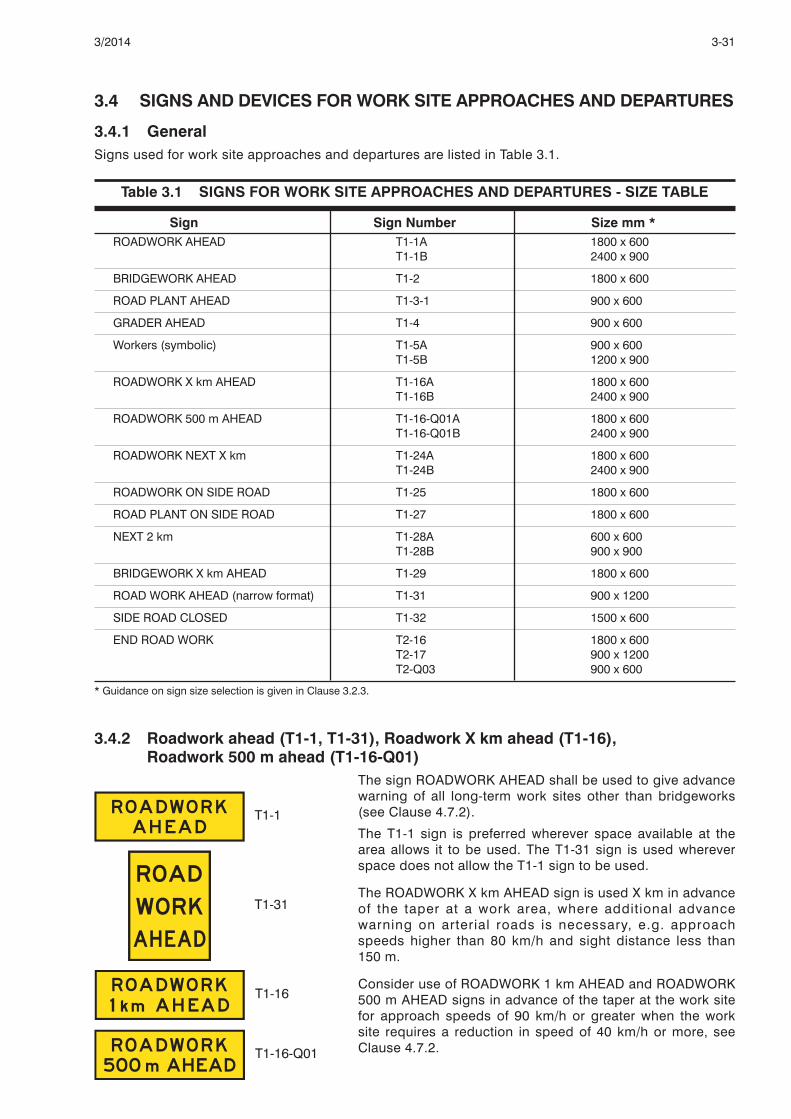
3.4 SIGNS AND DEVICES FOR WORK SITE APPROACHES AND DEPARTURES
3.4.1 GeneralSigns used for work site approaches and departures are listed in Table 3.1.
Table 3.1 SIGNS FOR WORK SITE APPROACHES AND DEPARTURES - SIZE TABLE
Sign Sign Number Size mm *ROADWORK AHEAD T1-1A 1800 x 600
T1-1B 2400 x 900
BRIDGEWORK AHEAD T1-2 1800 x 600
ROAD PLANT AHEAD T1-3-1 900 x 600
GRADER AHEAD T1-4 900 x 600
Workers (symbolic) T1-5A 900 x 600T1-5B 1200 x 900
ROADWORK X km AHEAD T1-16A 1800 x 600T1-16B 2400 x 900
ROADWORK 500 m AHEAD T1-16-Q01A 1800 x 600T1-16-Q01B 2400 x 900
ROADWORK NEXT X km T1-24A 1800 x 600T1-24B 2400 x 900
ROADWORK ON SIDE ROAD T1-25 1800 x 600
ROAD PLANT ON SIDE ROAD T1-27 1800 x 600
NEXT 2 km T1-28A 600 x 600T1-28B 900 x 900
BRIDGEWORK X km AHEAD T1-29 1800 x 600
ROAD WORK AHEAD (narrow format) T1-31 900 x 1200
SIDE ROAD CLOSED T1-32 1500 x 600
END ROAD WORK T2-16 1800 x 600T2-17 900 x 1200T2-Q03 900 x 600
* Guidance on sign size selection is given in Clause 3.2.3.
3.4.2 Roadwork ahead (T1-1, T1-31), Roadwork X km ahead (T1-16), Roadwork 500 m ahead (T1-16-Q01)
The sign ROADWORK AHEAD shall be used to give advancewarning of all long-term work sites other than bridgeworks(see Clause 4.7.2).
The T1-1 sign is preferred wherever space available at thearea allows it to be used. The T1-31 sign is used whereverspace does not allow the T1-1 sign to be used.
The ROADWORK X km AHEAD sign is used X km in advanceof the taper at a work area, where additional advancewarning on arterial roads is necessary, e.g. approachspeeds higher than 80 km/h and sight distance less than150 m.
Consider use of ROADWORK 1 km AHEAD and ROADWORK500 m AHEAD signs in advance of the taper at the work sitefor approach speeds of 90 km/h or greater when the worksite requires a reduction in speed of 40 km/h or more, seeClause 4.7.2.
3-313/2014
T1-1
T1-31
T1-16
T1-16-Q01

3.4.3 Bridgework ahead (T1-2), Bridgework X km ahead (T1-29)The sign BRIDGEWORK AHEAD is used to give advancewarning of long-term works on br idges (see Clause4.7.2(c)).
The sign BRIDGEWORK X km AHEAD is used on theapproach to a bridgework site under the same conditions asspecified for the ROADWORKS X km AHEAD (T1-16) inClause 3.4.2.
3.4.4 Workers (symbolic) (T1-5)The Workers (symbolic) sign is used to give warning ofpersonnel engaged in works on or adjacent to the travelledpath as specified in Clause 4.7.2(a). It shall comprise ablack symbol on a retroref lect ive f luorescent orangebackground.
Use of this sign is further dealt with in the following Clauses:
(a) At static worksites - Clause 4.2.
(b) At short-term works, open road areas - Clause 4.3.
(c) At short-term works, built-up areas - Clause 4.4.
(d) With mobile works - Clauses 3.12.3 and 4.6.4.
As this sign is used to warn of the presence of personnel, it shall only be displayed when they areactually working, or are visible to traffic, or both, and shall be removed or covered when workers haveleft the work area or are no longer visible to traffic.
The sign NEXT 2 km (T1-28) (see Clause 3.4.7) is used in conjunction with this sign when it is used forfrequently changing work areas (see Clause 4.3.4).
3.4.5 Road plant ahead (T1-3), Grader ahead (T1-4)The sign ROAD PLANT AHEAD is used at work sites wheremachinery is working on the roadway and no form of trafficcontrol, barrier or delineation is present to separate trafficfrom the work area. Where a grader alone is engaged inpavement, shoulder or roadside maintenance, thealternative sign GRADER AHEAD (T1-4) may be used.
The smaller ROAD PLANT AHEAD (T1-3-1) sign or theGRADER AHEAD sign should be used in conjunction withthe NEXT 2 km (T1-28) sign at a frequently changing workarea involving maintenance work carried out on the shoulderor verge by a grader or other machine (see Clause 4.3.4). Ata frequently changing work area where there are workers onfoot the Workers (symbolic) (T1-5) sign is used instead ofthese signs.
The sign should only be displayed when machinery isactually working.
3-32 3/2014
T1-4
T1-2
T1-29
T1-5
T1-3-1
T1-3-2

3.4.6 Roadwork next X km (T1-24), Roadwork on side road (T1-25), Road plant onside road (T1-27), Side road closed (T1-32)
The ROADWORK NEXT X km sign may be used tosupplement other advance signs wherever, over a distanceof 2 km or more, there are a series of two or more workareas within the one work site separated such that roadusers may not be aware that they are still within the worksite. Advance signing shall be provided in advance of eachindividual work area.
The ROADWORK ON SIDE ROAD and ROAD PLANT ONSIDE ROAD shall be used in advance of an intersection towarn of the relevant activities on the side road where there isinsufficient distance from the through road intersection tothe start of the works for turning traffic to be given adequatewarning. Where practicable, all warning and delineation ofthe works should be confined to the side road. These signsshall not be used on a side road to warn of works on athrough road about to be entered from the side road. TheROADWORK AHEAD (T1-1) or ROAD PLANT AHEAD (T1-3)may be appropriate in this case. A Speed Restriction signshall not be used in conjunction with these signs.
The SIDE ROAD CLOSED sign shall be used in advance ofan intersection where the side road is closed to all traffic.
3.4.7 Next 2 km (T1-28) and Next X km (T1-Q03)The NEXT 2 km sign may be used in conjunction with eitherthe Workers (symbolic) (T1-5), the ROAD PLANT AHEAD(T1-3-1) or the GRADER AHEAD (T1-4) signs where they areused to warn of a frequently changing work area (seeClause 4.3.4).
For shoulder grading and verge mowing on sealed roads inopen road areas (see Clause 4.3.5) and for maintenancegrading on unsealed roads (see Clause 4.5.2) the distancemay be increased up to 6 km, in which case T1-Q03 signshall be used.
3.4.8 End roadwork (T2-16, T2-17, T2-Q03)The END ROADWORK sign shall be used at the departureend of a work site where a temporary speed zone has beenimplemented. The sign may not be necessary at thedeparture end of a work site where a temporary speed zonehas not been implemented, on mobile works, progressivelymoving works, or where an END DETOUR sign (T2-23) isused (see Clause 3.6.3). The T2-16 sign is preferredwherever space available at the site allows it to be used. Thesmaller sized T2-17 and T2-Q03 signs may be used inconjunction with ROAD PLANT AHEAD (T1-3-1), GRADERAHEAD (T1-4) and Workers (symbolic) (T1-5) signs orwherever space does not allow the T2-16 sign to be used.
3-333/2014
T1-24
T1-25
T1-27
T1-32
T2-16
T2-17
T2-Q03
T1-28
T1-Q03

3.5 SIGNS AND DEVICES FOR REGULATORY CONTROL OF TRAFFIC
3.5.1 GeneralSigns used for regulatory control of traffic at work sites are listed in Table 3.2. Other regulatory signsspecified in Part 2 of this Manual may be used, where appropriate, if the usage specified in Part 2applies.
TABLE 3.2 SIGNS FOR REGULATORY CONTROL OF TRAFFIC - SIZE TABLE
Sign Sign Number Size mm *
GIVE WAY R1-2A 750 ht
R1-2B 900 ht
Speed Restriction R4-1A 450 x 600
R4-1B 600 x 800
R4-1C 900 x 1200
R4-1D 1200 x 1600
ROAD WORK R4-3A 450 x 300
R4-3B 600 x 400
R4-3C 900 x 600
END Speed Limit R4-12B 600 x 800
NO OVERTAKING OR PASSING R6-1A 750 x 900
STOP HERE ON RED SIGNAL R6-6 450 x 750
STOP/SLOW bat:
STOP face R6-8A 450 dia
R6-8B 600 dia
SLOW face T7-1A 450 dia
T7-1B 600 dia
Next ... m R9-6-1A 750 x 150
R9-6-1B 1000 x 200
ONE LANE R9-9A 600 x 400
R9-9B 750 x 500
Signals Ahead W3-3B 750 x 750
W3-3C 900 x 900
Speed limit AHEAD G9-79B 600 x 1000
STOP HERE WHEN DIRECTED T1-Q12A 900 x 600
T1-Q12B 1200 x 750
Traffic Controller Ahead/ T1-Q05A 900 x 1000
PREPARE TO STOP T1-Q05B 1200 x 900
PREPARE TO STOP T1-18A 900 x 600
T1-18B 1200 x 900
Signals Ahead T1-30A 900 x 600
(Rectangle)
* Except as noted in Clauses 3.5.5(a) and (b), guidance on sign size selection is given in Clause 3.2.3.
3-34 3/2014

3.5.2 Manual controlThe following are used for the manual control of traffic:
(a) Traffic controller ahead/Prepare to stop (T1-Q05)
The Traffic Controller Ahead/PREPARE TO STOP sign shallbe used to give advance warning where traffic may berequired to stop in compliance with the directions of a trafficcontroller.
The sign shall not be displayed when the traffic controller isnot actually in attendance controlling traffic.
(b) Stop/slow bat (R6-8,T7-1)
The STOP/SLOW bat shall be used by a traffic controller tocontrol traffic at any temporary obstruction or hazard (seeClause 4.10) . Retroref lect ive mater ia l used on theSTOP/SLOW bat shall be Class 1W material. The bat shallhave a handle a minimum of 1.8 m long to the underside ofthe sign. For night-time operations, an illuminated wandshould be used in conjunction with the bat.
(c) STOP HERE WHEN DIRECTED (T1-Q12)
This sign may be used at roadworks during traffic controlleroperations when vehicles may be required to stop at aparticular point.
This sign is to be a stand alone sign, additional to all othersigns.
3.5.3 Sign controlThe following signs are used for controlling traffic by signs only:
(a) Give way (R1-2), One lane (R9-9)
The GIVE WAY, ONE LANE sign assembly may be used toassign priority to one direction of travel past the work areawhen the travelled path is reduced to less than that requiredfor two lanes of traffic. This technique is appropriate for roador bridgeworks when-
(a) the traffic volume is 150 vpd or less and the postedspeed limit during roadworks is 70 km/h or less;
(b) each entry to the work area is visible from the other;
(c) the work area is less than 100 m in length; and
(d) there is sight distance to opposing traffic of desirably200 m or more beyond the far end of the work area fortraffic facing the GIVE WAY, ONE LANE sign assembly.
If advance warning of this sign is needed, the Give Way SignAhead sign (W3-2) (see Part 2 of this Manual) may be used.
3-353/2014
R6-8
T7-1
R1-2
R9-9
T1-Q05A T1-Q05B
T1-Q12

(b) No overtaking or passing (R6-1)
Where traffic at a single lane section is controlled by a GIVEWAY, ONE LANE sign assembly at one end in accordancewith Item (a) above, the NO OVERTAKING OR PASSING signshould be erected at the start of the single lane for traffic inthe opposite direction.
The NEXT . . . m sign shal l be used beneath the NOOVERTAKING OR PASSING sign to indicate the length of theno overtaking or passing zone. The sign is not required whenthe NO OVERTAKING OR PASSING zone applies to a bridge.
3.5.4 Traffic signal controlThe following traffic signals and signs are used to control traffic:
(a) Portable traffic signal - A portable traffic signal usually consists of two signal heads eachcomprising a three-aspect signal face, red, yellow and green; two vehicle detectors, a signalcontrol unit and a portable power source. The signal control unit is usually designed to permitvehicle-actuated, fixed-time or manual operation (see Note). Requirements for portable trafficsignals are specified in AS 4191. A typical signal unit is shown in Figure 3.1.
FIGURE 3.1 TYPICAL PORTABLE TRAFFIC SIGNAL
A portable traffic signal may be used to control traffic where the direction of flow in a one lanesection of road is to be alternated or where all traffic is to be stopped, e.g. at a machinery or haulroad crossing.
The procedures for operating portable traffic signals are given in Clause 4.11.
NOTE: All traffic and signal control equipment shall meet the applicable standards and specifications prescribed in Part 14 of theManual of Uniform Traffic Control Devices, the requirements of relevant Statutory Authorities and current QueenslandDepartment of Transport and Main Roads or local government specifications.
(b) Temporary fixed traffic signal - The design and installation of a temporary fixed traffic signal shallcomply with the relevant requirements of Part 14 of the Manual of Uniform Traffic Control Devices.
The use of temporary fixed traffic signals instead of portable signals should be considered onsafety grounds. The additional signal lanterns provide a more reliable control indication to traffic.
It will usually be found preferable to install fixed temporary signals for service periods in excess ofone to two weeks. Temporary signals will require a power supply for continuous use.
3-36 3/2014
R6-1
R9-6-1

(c) Signals ahead (W3-3), Signals ahead (T1-30)
If portable or temporary fixed traffic signals are used tocontrol traffic, the Signals Ahead sign (W3-3) shall be used togive advance warning. The PREPARE TO STOP (T1-18) signshall be used in conjunction with this sign.
For short-term use with portable signals the rectangularversion of this sign (T1-30) may be substituted.
Long distance warning of the existence of unexpected trafficsignals, e.g. in open road areas, may be required. The signassembly Signals Ahead (W3-3) and 1 km (W8-5-Q01)supplementary distance plate should be used in this case.
(d) Stop here on red signal (R6-6)
The STOP HERE ON RED SIGNAL sign shall be used toindicate where traffic must stop when there is no stop lineon the pavement. It is also recommended to supplement thestop line where one is provided.
(e) Prepare to stop (T1-18)
The PREPARE TO STOP sign shall be used in conjunction with the SIGNALS AHEAD sign (W3-3). Thematching size sign should be used.
3.5.5 Temporary speed limitsThe following signs are used to impose temporary speed limits:
(a) Speed restriction (R4-1)
The Speed Restrict ion sign shall be used to create atemporary speed zone in accordance with the requirementsand recommendations set out in Clause 4.9. It indicates thespeed limit which applies between the sign and the nextspeed control sign ahead.
A variable speed limit sign in accordance with Part 4 of theManual may be used.
Repeater Speed Restr ict ion signs may be erected atintermediate locations within the zone. The sign R4-1Bshould be considered the minimum size.
The end of a temporary speed zone shall be indicated by a Speed Restriction sign (R4-1) displayingthe appropriate speed limit for the road continuing beyond the works or the END Speed Limit (R4-12)sign where the conditions described in Item (c) apply. The END ROADWORK sign shall be usedtogether with the Speed restriction sign.
It is a legal requirement that a speed zone be terminated either by another regulatory speed controlsign, or other means as specified in traffic regulations.
These signs shall not be used without other appropriate warning signs. Where workers are present atthe site, the Workers (symbolic) (T1-5) sign (see Clause 3.4.4) shall be used together with the Speed
3-373/2014
W3-3
T1-30
R6-6
T1-18
Sign SizeNumber mm
T1-18A 900 x 600
T1-18B 1200 x 900
R4-1

Restriction sign. Speed Restriction signs continuously required for works which will be in progress forperiods longer than 2 weeks shall be erected 1 to 1.5 m above the level of the nearest edge of thetravelled path to the underside of the sign.
(b) Road work (R4-3)
The ROAD WORK supplementary plate may be used withSpeed Restriction sign (R4-1) to indicate the start of atemporary speed zone.
The A, B and C size signs are for use with the SpeedRestriction sign sizes A and B respectively.
(c) End speed limit (R4-12)
Subject to Clause 3.5.5 (a), this sign may be used toterminate a temporary speed zone where it is not practicableor desirable to display the speed limit applying beyond thezone by means of the R4-1 sign. This case could typicallyoccur where although the continuing speed limit (generallimit or zoned limit) is 100 km/h, road surface, alignment orother conditions will not allow traffic to travel safely at thatspeed.
(d) Speed Limit AHEAD (G9-79)
This sign shall be used to provide advance warning of thestart of a temporary speed zone in accordance with Clause4.9.5(a) where a speed zone of intermediate value is notproposed.
3.6 DETOUR SIGNS
3.6.1 GeneralSigns used for the guidance of traffic in advance of and through detours, are listed in Table 3.3.
Table 3.3 SIGNS FOR DETOURS - SIZE TABLE
Sign Sign Number Size mm *
NO ENTRY R2-4B 600 x 600R2-4C 750 x 750
No Left Turn R2-6B (L) 600 x 600R2-6C (L) 750 x 750
No Right Turn R2-6B (R) 600 x 600R2-6C (R) 750 x 750
All Traffic Turn R2-14B (L or R) 900 x 1200
LOW BRIDGE AHEAD ... m, G9-3 (L or R) 1700 x 900HIGH VEHICLES DETOUR
LOAD LIMIT ... t ON BRIDGE, G9-4 (L or R) 1700 x 900HEAVY VEHICLES DETOUR
DETOUR FOR HIGH VEHICLES G9-5-1 (L or R) 1300 x 350
DETOUR FOR HEAVY VEHICLES G9-5-2 (L or R) 1400 x 350
3-38 3/2014
R4-3
R4-12
G9-79

Table 3.3 SIGNS FOR DETOURS - SIZE TABLE (cont.)
Sign Sign Number Size mm *
Two-way traffic (Rectangular - regulatory) R2-11A 450 x 600R2-11B 600 x 800
LOCAL TRAFFIC ONLY G9-40-2A 900 x 600G9-40-2B 1200 x 900
Two-way traffic (Diamond) W4-11B 750 x 750W4-11C 900 x 900W4-11D 1200 x 1200
DETOUR AHEAD T1-6A 1200 x 600T1-6B 1800 x 900
END DETOUR T2-23 1200 x 600
Two-way traffic T2-24A 900 x 600(Rectangular)
DETOUR (Arrow) T5-1A (L or R) 1200 x 300T5-1B (L or R) 1800 x 450
Detour marker T5-6A 450 x 450
* Application of the sign size designations in the T Series is given in Clause 3.2.3.
3.6.2 Detour ahead (T1-6)The DETOUR AHEAD sign shall be used to give advancewarning of a detour bypassing a section of the normalroadway which is not trafficable or on which work is beingcarried out. The detour may be either via other roads orstreets, or via a side track constructed for that purpose (seeClause 4.14).
3.6.3 End detour (T2-23)The END DETOUR sign should be used to indicate that adetour has ended wherever road users need to be advisedthat it has returned to the original route.
3.6.4 Detour (left or right) (T5-1)The DETOUR sign (T5-1B) shall be used to indicate thedirection and location for traffic to leave the normal roadwayto detour via existing roads or streets or via a side trackbypassing an obstruction (see Clause 4.14). It will usually benecessary to use the advance sign DETOUR AHEAD (T1-6)in conjunction with this sign.
DETOUR signs (T5-1A) should be used, if necessary, toreassure and guide traffic along the route of the detour.
3.6.5 Detour marker (T5-6)The Detour Marker may be used in lieu of the DETOUR(T5-1) sign to guide and reassure road users along the routeof a detour if the DETOUR sign is likely to misdirect roadusers other than those following the detour. It is typicallyused in built-up areas where traffic is detoured via sidestreets.
The signboard shall be designed to be mounted with thearrow either vertically upwards, or to the left or right.
3-393/2014
T1-6
T2-23
T5-6
T5-1 (R)
T5-1 (L)

3.6.6 Low bridge ahead ... m, High vehicles detour (G9-3)Load limit on bridge ... t gross, Heavy vehicles detour (G9-4)
The signs LOW BRIDGE AHEAD ... m, HIGH VEHICLESDETOUR and LOAD LIMIT ON BRIDGE ... t GROSS, HEAVYVEHICLES DETOUR shall be erected at locations where it isessential that high or heavy vehicles detour to avoidstructures which have a low clearance or a load limitation(see Clause 4.14.10). They shall be erected in advance ofthe junction with the alternative route.
The alternative legend NARROW BRIDGE AHEAD … mWIDE VEHICLES DETOUR may be substituted on sign G9-3.
3.6.7 Detour for ... vehicles (G9-5)The DETOUR FOR .... VEHICLES sign shall be erected at thejunction with an alternative route where certain classes ofvehicle are unable to negotiate the work area. The wordsWIDE or LONG may be used in lieu of HIGH and HEAVY,where appropriate.
3.6.8 Two-way traffic (W4-11)Two-way traffic (T2-24)
The Two-way Traffic sign is used to warn road users that theroadway carries two-way traffic.
The signs should be erected on both sides of the road at thebeginning of each section over which two-way conditionstemporarily apply. A second set of signs should be locatedbetween 100 m and 400 m after the start of the two-waysection with additional sets of signs placed at intervals ofapproximately 1.5 km where the speed limit is greater than70 km/h, or otherwise at 400 m intervals.
The signs should be used for the following situations:
(a) where a two-way road is the extension of a one-wayroad.
(b) on any other road where, because of the roadconditions, it is not clear whether a particular roadwaycarries traffic in one or both directions.
(c) To face traffic soon after entering from a side road ineither of the conditions in Items (a) and (b).
The largest sign (W4-11D) shall be used for the situation initem (b) above.
The rectangular version of this sign (T2-24) is for short termuse only.
Where a roadway designed or normally used for one-waytraffic is temporarily being used for two-way traffic, or wherelegislation prescribes that roadways, e.g. service roads, areone-way but two-way operation is desirable or necessary,the regulatory TWO-WAY sign (R2-11) shall be used at eachend of the section of road to indicate the points at which thetwo-way traffic regulation temporarily applies.
3-40 3/2014
G9-3 (L)
G9-4 (L)
G9-5-1(L)
G9-5-2(L)
W4-11
T2-24
R2-11

3.6.9 All traffic turn (R2-14)The All Traffic Turn sign may be used at situations where allapproaching traffic must turn in the direction indicated bythe arrow.
3.6.10 Local traffic only (G9-40-2)The LOCAL TRAFFIC ONLY sign may be used at detourswhere local traffic is permitted to enter the work area (seeClause 4.14.5).
3.7 ROAD CONDITION SIGNS
3.7.1 GeneralSigns used to warn road users of road conditions are listed in Table 3.4.
Table 3.4 ROAD CONDITION SIGNS - SIZE TABLE
Sign Sign Number Size mm *
Slippery T3-3A 900 x 600
T3-3B 1500 x 900
SOFT EDGES T3-6A 900 x 600
ROUGH SURFACE T3-7A 900 x 600
T3-7B 1500 x 900
Loose Stones T3-9A 900 x 600
T3-9B 1500 x 900
NEW WORK, NO LINES MARKED T3-11 1500 x 900
NO LINES, DO NOT OVERTAKE T3-12 1500 x 900
UNLESS SAFE
GRAVEL ROAD T3-13 900 x 600
LOOSE SURFACE T3-14A 900 x 600
T3-14B 1500 x 900
X km/h (portrait format) T3-16-1A 600 x 600
T3-16-1B 900 x 900
X km/h (landscape format) T3-16-2A 900 x 400
T3-16-2B 1500 x 600
* Application of sign size designations in the T Series is given in Clause 3.2.3.
3-413/2014
R2-14 (L)
G9-40-2

3.7.2 Slippery (T3-3), Soft edges (T3-6), Rough surface (T3-7), Gravel road (T3-13),Loose stones (T3-9), Loose surface (T3-14)
The Slippery, SOFT EDGES, ROUGH SURFACE, GRAVELROAD, Loose Stones and LOOSE SURFACE signs are usedto warn road users of conditions which render the surface ofthe roadway or its edges temporarily hazardous. The signsshould be erected 2D (see Table 4.2) metres before thebeginning of the hazard. Road condition signs placed otherthan at an active work area may not require the use of otheradvance warning signs in conjunction, provided that thenormal traffic lanes are not obstructed. If the hazardousconditions extend over a considerable length the signs mayneed to be repeated at regular intervals of not more than500 m. Advisory Speed signs (T3-16) (see Clause 3.7.3) maybe required in conjunction with these signs.
The Slippery sign (T3-3) may be used to warn of a slipperycondition caused by water, ice or loose material on the roadsurface. In the latter case, the sign LOOSE SURFACE(T3-14) may be used as an alternative to the Slippery sign.
The Loose Stones sign (T3-9) is used for any situation whereflying stones may be a hazard. It may also be used toprotect the road surface against excessive loss of aggregateand to warn of the possibility of flying stones where freshbituminous surfacing work has been carried out.
Refer to Clause 4.9.3 for speed zones for traffic safetypurposes particularly where loose material or stones arepresent on the road surface or for new sprayed seal workswhere higher speeds may damage the new seal.
Note: Where work is carried out under MRTS 11 or other specification whichrequire regulatory speed limits to be posted after resealing works, therequirements of those specifications regarding the installation of speed limitsignage shall apply.
3.7.3 Advisory Speed signs (T3-16)Advisory Speed signs may be used in conjunction with signsin the Road Condition Series (see Clause 3.7.2) in situationswhere a reduction in speed is desirable for road usercomfort or protection of damaged pavement or partiallycompleted works. They are not appropr iate where aroadworks speed limit is required for either traffic safety orworkplace safety.
If the T3-16-1 sign is used, it is designed to be placedbeside the sign to which it refers. The T3-16-2 sign isdesigned to be placed under it.
These signs shall not be used without another sign.
3-42 3/2014
T3-16-1
T3-16-2
T3-3
T3-6
T3-7
T3-13
T3-9
T3-14LOOSE
SURFACE

3.7.4 New work, no lines marked (T3-11)No lines do not overtake unless safe (T3-12)
These signs are used in advance of locat ions wherepavement markings normally required for driver guidancehave been removed or have not been placed on newsurfacing work.
The T3-11 sign should be used in locat ions such asmultilane or one-way roadways where there is no overtakingrisk from oncoming traffic.
The T3-12 sign shall be used at locations where barrier lineswould normally be installed and should be used in anysi tuat ion on two-way roadways where there wi l l beovertaking in an oncoming traffic lane.
3.8 SIGNS AND DEVICES FOR LANE AND ROAD CLOSURES
3.8.1 GeneralSigns used to effect lane and road closures are listed in Table 3.5.
Table 3.5 SIGNS FOR LANE AND ROAD CLOSURES - SIZE TABLE
Sign Sign Number Size mm *
ROAD CLOSED T2-4-Q01 1800 x 300
Lane Status (2 lane) T2-6-1A 1200 x 900
T2-6-1B 1800 x 1200
Lane Status (3 lane)* T2-6-2A 1800 x 900
T2-6-2B 2400 x 1200
EXIT CLOSED T2-20 2100 x 1200
... EXIT CLOSED (arrow) T2-21 (L or R) 2600 x 1700
ALTERNATIVE
ROAD CLOSED ... km AHEAD T2-Q02 1800 x 600
* Lane Status signs for more than three lanes may be designed to be similar to this sign.
3.8.2 SignsThe following signs are used for lane and road closures:
(a) Lane status (T2-6)
The Lane Status sign is used where one or more lanes of amulti-lane roadway are closed.
The Lane Status sign is not used where a turn lane isclosed. A No Right Turn sign or No Left Turn sign shall beused as appropriate.
The Lane Status sign shall be used only to give advancewarning of lane closures and not in lieu of adequate signingand delineation of the closure.
The ‘bars’ indicate the closed lanes while the arrowsindicate lanes available to traffic. This sign may be madewith removable and reversible symbols so that the numberand location of each type can be varied to suit the particular
3-433/2014
T3-12
T3-11
T2-6-1
T2-6-2

lane closure in operation. Versions of these signs designed along the same lines to show more thanthree lanes may also be used.
Whenever practicable the Lane Status sign should be placed on both sides of the road.
(b) Road closed (T2-4-Q01)
The ROAD CLOSED sign shall be used where a roadway isclosed to traffic. Barrier boards shall be erected across theroadway in conjunction with the sign and the bars should bealigned to point to the sign (see Figure 4.13).
Consideration should be given to providing traffic detours.
The ROAD CLOSED ... km AHEAD sign may be placed inadvance of the road closure. This sign should be erected atthe junction with an alternative route, if practicable.
(c) ... Exit closed - alternative (T2-21)
The . . .EXIT CLOSED - ALTERNATIVE sign is used onfreeways at the exit in advance of the closed exit if this is anappropriate alternative route. Signs may be ordered forspecific exits or bolt-on overlays may be utilised (see Clause4.14.9).
(d) Exit closed (T2-20)
The EXIT CLOSED sign is placed in advance of a closedfreeway exit.
3.8.3 BarricadesBarricades comprise either barrier boards (see Figure 3.2) or stand-alone non-interconnectedlightweight modules. They shall be used to inhibit access to a work area. They should be erectedapproximately perpendicular to the direction of traffic flow at intervals not exceeding 100 m. Barricadesshall not be used for delineation purposes.
The requirements for each type of barricade are as follows:
(a) Barrier boards
Barrier boards shall be 150 mm to 200 mm in height and not more than 4 m in length. They shouldbe mounted on trestles or fixed posts at about 1 m above the pavement. The colour combinationused for barrier boards shall be alternate diagonal stripes of black and retroreflective yellow,terminating in yellow at each end as illustrated in Figure 3.3.
They shall not be placed parallel to the direction of traffic flow. Barrier boards so placed canbecome a spearing hazard if struck end on by an out-of-control vehicle.
(b) Stand-alone lightweight modules
Stand-alone non-interconnected lightweight modules when used as barricades shall be placedbehind a line of delineating devices.
Both types of device shall satisfy the requirements of Impact tests 70 and 71 of NCHRP 350 for workzone traffic control devices.
NOTE: Tests 70 and 71 of NCHRP 350 are used to assess the structural integrity of traffic control devices. Both tests use an 820 kg testvehicle which impacts the device along the central axis of the vehicle with an impact angle of 20 degrees or less. Test 70 impacts at 35km/h (Test Level 1) and Test 71 impacts at 70 km/h (Test Level 2). Both tests determine the structural integrity of the impacted deviceby considering whether or not the device fragments, generating projectiles or spearing elements that could be hazardous to theoccupants of errant vehicles or nearby pedestrians.
3-44 3/2014
T2-Q02
T2-4-Q01
T2-21 (L)
T2-20

Note: In this figure, vehicles pass to the left of the board. The bars should be aligned to point down to the right for vehicles to pass tothat side.
Figure 3.2 TYPICAL BARRIER BOARD
3.9 DEVICES FOR DELINEATING AND INDICATING THE TRAVELLED PATH
3.9.1 Traffic cones and temporary bollardsTraffic cones and temporary bollards should be used on works to define the traffic path within the worksite.
Requirements and recommendations for their use are as follows:
(a) Traffic cones
Traffic cones shall comprise cones of fluorescent red or fluorescent orange material that isresilient to impact. Various sizes available should be used as follows:
(i) Small cones
450 to 500 mm height - most built-up area and open road applications including footpaths,shared paths and bicycle paths where posted speed limits (prior to roadworks) do not exceed70 km/h.
(ii) Standard size cones
700 mm height or greater all other road applications where posted speed limits (prior toroadworks) exceed 70 km/h. Standard size cones may also be used on lower speed roads.
(b) Temporary bollards
Temporary bollards shall comprise a vertical parallel sided or tapered tube of fluorescent orangeor red material that is resilient to impact. They shall be at least 750 mm in height and a minimumof 100 mm in diameter.
For night-time use, cones and bollards shall be fitted with a white horizontal retroreflective band havinga retroreflective performance at least equal to Class 1W material as specified in AS/NZS 1906.1. Thesize and positioning of retroreflective bands on traffic cones and bollards are given in Table 3.6.
Table 3.6 SIZE AND POSITIONING OF RETROREFLECTIVE BANDS ON TRAFFIC CONESAND BOLLARDS (millimetres)
Item Height Band width Distance from top ofdevice to band
Cone 450 to 500 150 130 ±5
Cone 700 and over 250 220 ±5
Bollard all heights 250 220 ±5
3-453/2014

Cones and bollards shall be designed to be stable under reasonably expected wind conditions and airturbulence from passing traffic. However, they can be displaced by passing traffic and therefore, unlessworkers are there to replace them, should not be used unless they are securely fixed to the pavementor weighted to provide adequate stability from passing traffic when unattended.
Recommended spacings of cones and bollards are given in Table 3.7. Spacing of cones and bollardsmay need to be reduced to as little as 1 m if needed to prevent traffic taking a wrong turn or wrongopening through a line of bollards. The tabulated traffic speed shall be the speed of the traffic at thelocation where the line of cones or bollards is placed.
TABLE 3.7 RECOMMENDED MAXIMUM SPACING OF CONES AND BOLLARDS
NOTES:
1 This spacing may be extended to 60 m where the length of the line of cones or bollards exceeds 1 km but not adjacent to locationswhere there are workers on foot.
2 This spacing may need to be reduced on curves or crests, or if the row of cones is not clearly defined at night.
3 Posted Speed Limit prior to roadworks.
3.9.2 Roadworks delineatorsRoadworks delineators shall comprise red delineators on the left side and white delineators on theright (two-way roadway) or yellow on the right (one-way roadway).
Delineators used at or near works on roads shall meet the requirements of AS/NZS 1906.2 for eitherthe sheeting or discrete device type. Delineators made from orientation-sensitive material shall bemade and installed at the material manufacturer's recommended orientation for optimum performance.
NOTE: Orientation-sensitive material is generally regarded as material whose CIL at the specified measurement angles changes bymore than 10% as it is progressively rotated in its plane.
Delineators should be erected 1 m minimum from the edge of the travelled path and at a uniformheight of approximately 1 m above the road surface. Delineator posts should be frangible or otherwisenon-hazardous.
Delineators should be installed so as to provide a single continuous line defining the travelled path.The spacing of delineators should be as follows:
(i) Immediately adjacent to or through work areas -
(A) 24 m maximum at posted speed limits up to 70 km/h;
(B) 60 m maximum at higher posted speed limits.
(ii) On side tracks and detours - as specified in Clause 4.14.6.
Purpose and usage Posted Speed Limit3,km/h
Recommended maximumspacing, m
All purposes ≤50 4
Centre-line on approach to a traffic controller position(Clause 4.10.2)
All cases(see Clause 4.10.4)
4
Outer edge of traffic lanes - e.g. works on shoulder orparking lane
60 to 70>70
1824 1
Separating opposing traffic on a 2-lane, 2-way road - e.g.partial or complete lane closure
60 to 70>70
1218
Separating opposing traffic on a multilane undivided road -e.g. as part of a lane closure
60 to 70>70
1218
Adjacent to a closed lane on a multilane undivided road60 to 70
>701824
Merge tapers (see Clause 4.8.2)60 to 70
>709
12
Lateral shift tapers (see Clause 4.8.2)60 to 70
>701218
Protecting freshly painted lines60 to 70
>702460 2
3-46 3/2014

Temporary road safety barrier systems installed through work areas should be delineated atapproximately 20 m spacings. Barriers installed to form curves or tapers may require additionaldelineation.
Typical post-mounted delineators are shown in Figure 3.3.
Note: Delineator colour is specified in Clause 3.9.2.
FIGURE 3.3 EXAMPLES OF ROADWORKS DELINEATORS
3-473/2014

3.9.3 Temporary hazard markers (T5-4, T5-5, T5-Q02)
Temporary Hazard markers should be used to show anylateral change of direction of the travelled path through awork site and to delineate hazards and non-trafficable workareas adjacent to the travelled path. They should be erectedwith their edge about 1 m from the edge of the travelled pathand at a uniform height above the road surface, and thechevrons shall always point to the side to which traffic isrequired to pass.
On works extending overnight or being conducted at nightwhere an obstruction encroaches onto the roadway, a seriesof T5-4 Temporary Hazard markers may be used in lieu oftraffic cones or bollards to form the taper guiding traffic awayfrom the obstruction. The T5-4 markers should be spaced sothat as the taper is approached they appear as a continuousline (see Clause 4.8.3). If temporary delineation is requiredon both sides of the vehicle path at a taper, hazard markersshould only be used on the side primarily steering trafficaway from the obstruction. Since in most cases two parallellines of hazard markers will lead to confusing visual patterns,traffic cones or bollards should be used on the other side.For daytime-only works, traffic cones or temporary bollardsused in conjunction with the T5-5 Temporary Hazard markeras indicated below, will generally suffice.
The T5-5 Temporary Hazard marker may be used on works extending overnight, in lieu of the T5-4marker, in confined areas where there is insufficient space to use the wider marker.
The T5-5 marker should also be used at short-term works to indicate the beginning of a line of trafficcones or bollards where the devices themselves may not be sufficiently visible to approaching traffic.
If other signs, such as ROAD CLOSED or DETOUR, are required at a site in conjunction with a line ofTemporary Hazard markers they should be placed so as to appear above but not among the line ofTemporary Hazard markers.
The Temporary Collapsible Chevron delineator T5-Q02 may be used to delineate hazards and non-trafficable work areas adjacent the travelled path.
3.9.4 Pavement markingsThis Clause applies to roads where there were pavement markings in existence prior to the works.
Appropriate pavement markings should be provided or maintained to guide traffic through and past awork area. The following principles apply:
(a) Where existing markings are satisfactory, they should be maintained in good condition throughoutthe period of the work.
(b) If existing markings are not appropriate or are potentially misleading, they should be removed andreplaced by more suitable markings, taking care that markings are not obliterated by materialwhich may become slippery.NOTE: It is inadvisable to obliterate markings using black or grey paint as under certain light or wet weather conditions (e.g.specular illumination by opposing vehicle headlights) they may appear indistinguishable from white markings.
(c) Consideration should be given to the use of retroreflective pavement marking tape for alltemporary lines as the removal of road marking paint is often difficult and may leave a mark whichmay be mistaken for a line under certain lighting or wet weather conditions.
3-48 3/2014
T5-4 Sign SizeNumber mm
T5-4 1500 x 450
T5-5 600 x 600
T5-Q02 250 x 1200*T5-5
T5-Q02
* This dimension may vary from 1140 to 1200 mm.

(d) Temporary lines used to guide traffic through substantial diversions or changes in direction,should be supplemented by raised retroreflective pavement markers.
(e) Where, during or at the conclusion of pavement-surfacing works, a section of roadway is to be leftfor a period of time without linemarking, temporary raised retroreflective pavement markers shouldbe used to provide delineation of the separation or lane lines. The use of appropriate signswarning of the need to exercise caution in the absence of lines is set out in Clause 3.7.4.
3.9.5 Raised retroreflective pavement markersRaised retroreflective pavement markers (RRPMs) complying with AS 1906.3 may be used inconjunction with temporary pavement markings at long-term work sites. The spacing and applicationshould be as specified for permanent use in Part 2 of this Manual.
Temporary RRPMs recommended under Clause 3.9.4(e) at freshly surfaced pavements should besufficiently robust to survive under traffic until permanent markings are installed.
Where special emphasis of a dividing line is required, e.g. where a multilane or divided road has beentemporarily reduced to a two-way road, lane dividers typically comprising a larger base than the RRPM,with a vertical flexible flap attached and incorporating a retroreflector, may be placed along the dividingline, generally at the same spacing as RRPMs.
3.9.6 Temporary kerbingTemporary kerbing may be used to form temporary medians, traffic islands or pavement edges duringlong-term works. Such kerbing shall be not greater than 150 mm in height and should be securelyfastened to the pavement. It should be white, and as seen by approaching traffic shall appear as acontinuous line at least 150 mm wide.
3.10 CONTAINMENT FENCES AND ROAD SAFETY BARRIER SYSTEMS
3.10.1 Containment fencesContainment fences comprising tapes, plastic mesh fencing or longitudinal channelising barricadesmay be used to provide visible containment as described in Items (a) and (b), and Clause 3.10.2 insituations where physical protection by use of a road safety barrier system (see Clause 3.10.3) is notwarranted.
All types of containment fence shall have sufficient stability to resist displacement, fracture ordeflection of more than 0.5 m resulting from all expected wind conditions, air turbulence from passingtraffic and minor vehicular impacts.
Descriptions and use of tapes and mesh fencing used as containment fences are as follows:
(a) Tapes
Containment tapes may be used to contain workers on foot and plant within the safe workplaceboundary established at the particular work site in accordance with Clause 4.2. The tape shouldbe a minimum of 100 mm wide with alternate of stripes contrasting colour, and should besupported approximately 1 m above ground level with supports spaced so that the minimumheight of the tape above ground is not less than 800 mm. The maximum breaking strength shouldbe low enough not to cause hazard to any vehicle or motor cycle which might run into it. Tapesshall not be used for pedestrian containment adjacent to traffic.
(b) Plastic mesh fencing
Plastic mesh fencing may be used for pedestrian containment as well as for the containment ofworkers on foot and plant as in Item (a). It comprises a flexible orange mesh approximately 1 mhigh. It shall be supported so that the top of the fence is at least 800 mm above ground level at alltimes.
3.10.2 Longitudinal channelising barricadesLongitudinal channelising barricades shall comprise interconnected lightweight modules such asplastic water ballasted modules. They may be used either as containment fences for workers orpedestrians, or as delineation devices in situations where a road safety barrier system as specified inClause 3.10.3 is not required. Their use shall be subject to the following:
3-493/2014

(a) They shall satisfy the requirements of Impact tests 70 and 71 of NCHRP 350 for work zone trafficcontrol devices together with such additional tests as may be required in the revised edition of AS3845 (a new edition of AS 3845 was in preparation at time of publication of this Part of theManual).
(b) They shall be marked ‘NOT A SAFETY BARRIER’ in letters at least 50 mm high.
(c) Edge clearances to traffic shall be in accordance with Clause 4.13.4(a).
Stand-alone, non-interconnected lightweight modules shall not be used for any purpose. Their useshall be confined to inhibiting access to a work area as specified in Clause 3.8.3.
3.10.3 Road safety barrier systemsRoad safety barrier systems are designed to provide a physical barrier between the travelled path andthe work area, which will inhibit penetration by an out-of-control vehicle (see Note) and will havevehicle redirecting properties. They are typically used between traffic and a severe hazard such as adeep excavation, a bridge pier or a hazardous stockpile, and for the protection of workers and non-vehicular road users in vulnerable situations where lateral clearance to moving traffic would otherwisebe insufficient for safety. They may also be used to separate opposing traffic.
NOTE: The satisfactory performance of a barrier system will depend on its being struck by a vehicle no larger than the ‘design’ vehiclefor which it is to be designed. Selection of the design vehicle should be subject to a risk assessment taking into account traffic mix pastthe site and the nature and length of the works.
Vehicles can be protected from collisions with hazardous fixed objects by crash attenuators as analternative to safety barrier systems (see Clause 3.10.4).
The type selection and installation of a temporary road safety barrier system including positioning andend treatments shall be in accordance with AS/NZS 3845. For the protection of workers from dynamicdeflection of the barrier in a crash, if the work area is close to the rear of the barrier a containmentfence or longitudinal channelising barricade shall be placed behind the barrier a clear distance equalto the likely dynamic deflection. Data on the dynamic deflection of the barrier type used whenimpacted by the selected design vehicle will be needed to determine the positioning of thecontainment fence. The positioning of protective fencing behind a barrier is illustrated in Figure 3.4.
The positioning of barriers in relation to high obstructions such as power poles, bridge piers orunderpass scaffolding shall take into account the likely extent of body roll of a high vehicle striking thebarrier.
Fittings other than delineators shall not be attached to safety barrier systems unless they have beendesigned to accommodate the fitting.
Edge clearances to traffic shall be in accordance with Clause 4.13.4(c).
FIGURE 3.4 PROTECTIVE FENCING BEHIND A SAFETY BARRIER SYSTEM
3.10.4 Temporary crash attenuatorsHazardous fixed objects that have become exposed to traffic due to roadwork, such as bridge piers orsafety barrier ends, may need to be equipped with purpose designed energy absorbing terminaldevices to reduce the severity of collision by an out-of-control vehicle.
3-50 3/2014

The need should be determined from a risk assessment that takes full account of the additional riskdue to works on roads.
NOTE: Reference should be made to NCHRP 350 and NCHRP 358 for the selection, design and positioning of temporary crashattenuators.
3.11 LAMPSFlashing yellow lamps may be used at work sites to draw attention to advance signs. They are typicallyused with the ROADWORK AHEAD (T1-1) or BRIDGEWORK AHEAD (T1-2) signs in areas where roadlighting is poor or absent. Flashing lamps shall not be used for delineation purposes.
NOTE: The use of steady or ripple lamps for any purpose including delineation has now been omitted from this Part of the Manual. Anymandatory requirements for the use of flashing lamps have also been omitted.
3.12 VEHICLE-MOUNTED SIGNS AND DEVICES
3.12.1 Vehicle-mounted warning deviceA vehicle-mounted warning device shall consist of one or other of the following:
(a) A single yellow beacon lamp for use on a vehicle not normally used for any works on roads, or ona plant item with protection for workers and road users, or an inspection vehicle operating inaccordance with Clause 4.3.6 (a) (ii) or (b).
(b) A pair of yellow beacon lamps for use on vehicles (e.g. patrol trucks) used on all roads for anywork being carried out without the protection of a static work site. The lamps should be positionedon the vehicle so that at least one and preferably both lamps are visible from any direction.
(c) An illuminated flashing arrow sign as specified in Clause 3.12.2 for any work, including thesituations in Items (a) and (b) and for mobile works where indicated in Clause 4.6.
The vehicle-mounted warning device shall be mounted as high as practicable on the vehicle for bestvisibility to other traffic, e.g. on top of the cab of a truck. It may need to be placed near the rear of thevehicle if a cab-mounted sign could be obscured by a load. Supplementary signs used in conjunctionwith the illuminated flashing arrow sign (see Clause 3.12.3), may be mounted either in conjunction withthat sign or elsewhere in a prominent position on the vehicle.
Where signs are mounted on the device or elsewhere on a vehicle, they shall be capable of beingremoved from view (e.g. by covering, folding or turning off) when not needed.
3.12.2 Illuminated flashing arrow signThis sign comprises a matrix of yellow lamps in the form of an arrow that is flashed in a cyclic mannerto provide advance warning of a temporary diversion. It includes a backing board for the lampstogether with ancillary equipment necessary for mounting and operating the sign, and reducing its lightoutput (dimming) for night-time use. Requirements for this sign are specified in AS/NZS 4192.
The following three size designations are used:
(a) Size A
1260 mm x 650 mm - designed for roof mounting on a light vehicle, and is typically used for short-term lane closure and mobile works on roads with a posted speed limit (prior to roadworks) of 60km/h or less.
(b) Size B
1500 mm x 770 mm - designed for cab mounting on a truck. It is typically used for short-term laneclosures or mobile works, and is suitable for use on roads with a posted speed limit (prior toroadworks) of greater than 60 km/h.
(c) Size C
2400 mm x 1200 mm - trailer mounted with its own power supply and suitable for medium andlong-term lane closures on multilane roads with a posted speed limit (prior to roadworks) ofgreater than 60 km/h, freeways and elsewhere where a high level of long distance advancewarning is desirable for safety.
High intensity flashing lamps may be used in conjunction with this sign provided that the lamps areeither appropriately shielded or laterally or vertically displaced from the edge of the sign to avoidvisually corrupting the arrow shape or its directional effect.
3-513/2014

Requirements for the flashing of different patterns of the lights are as follows:
(i) When traffic is expected to pass the sign on a particular side and can do so in safety, i.e. it is notrequired to seek a gap in oncoming traffic, the bar of the arrow and the barb directing traffic tothat side shall be flashed.
(ii) When the sign is used to give a general warning of works activity ahead including mobile works,but either the sign is located clear of the traffic path or the display of an arrow would not beappropriate for some other reason, either the bar of the arrow only or the four corner lights at theextremities of the barbs shall be flashed. In the latter case diagonal pairs should be flashedalternately.
A typical sign as part of a vehicle-mounted warning device is shown in Figure 3.5.
FIGURE 3.5 ILLUMINATED FLASHING ARROW SIGN
3.12.3 Supplementary vehicle-mounted signsThe following lists signs appropriate for use in conjunction with the illuminated flashing arrow signwhere necessary to warn road users of the presence of workers on foot or the nature of the work:
(i) Workers (symbolic) (similar to sign T1-5) - This sign shall be used on all vehicles in a mobile worksconvoy (see Clause 4.9) whenever workers on foot are part of the operation. The colourrequirements for this sign are the same as specified for the T1-5 sign in Clause 3.4.4. The symbolsize shall be not less than that specified for sign No. T1-5A or B according to the requirements ofClause 3.2.3.
(ii) LINE MARKING (T6-Q07) - This sign shall be used on advance warning vehicles as well as on thework vehicle. The colour requirements for this sign are specified in Item (a) below.
Where used, these signs shall be mounted either on the vehicle-mounted warning device along withthe flashing arrow sign, or elsewhere in a permanent position on the body of the vehicle.
Standard signboard sizes are not specified for these signs. They shall be tailored to suit the positioningand mounting arrangements on the vehicle.
Legends shall be of sufficient size to be read by drivers at a distance of at least D (where D = 60 to80 m).
The following signs may be used in conjunction with other signs and devices to warn traffic that work isin progress on the road ahead. The signs incorporate a panel of chevrons which is adjusted to indicatethe side of the vehicle to which traffic should pass.
3-52 3/2014

Table 3.8 SUPPLEMENTARY VEHICLE MOUNTED SIGNS - SIZE TABLE
Sign Sign number Size, mm*
KEEP CLEAR (with chevron panel) T6-Q02A (L or R) 1200 x 600
T6-Q02B (L or R) 1800 x 750
LINE MARKING (with chevron panel) T6-Q06A (L or R) 1200 x 600
T6-Q06B (L or R) 1800 x 750
LINE MARKING T6-Q07A 1200 x 300
T6-Q07B 1800 x 450
* Guidance on size selection is given in Clause 3.2.3.
(a) Line marking (T6-Q06, T6-Q07)
The LINE MARKING sign T6-Q06 or T6-Q07 shall be used onlinemarking vehicles while traffic lines are being painted.
The T6-Q06 sign incorporates a panel of chevrons which isadjusted to indicate whether the overtaking manoeuvre is tothe left or to the right. Lamps shall be used with this sign.
The T6-Q07 sign is mounted above an illuminated flashingarrow sign (see Clauses 3.12.1 and 3.12.2 and Figure 4.3).
(b) Keep clear (T6-Q02)
The KEEP CLEAR (T6-Q02) sign may be used on pavementtesting vehicles for pavement testing operations which arecarried out at a slow speed (about 1-2 km/h).
3.12.4 Painting of vehicles and machineryVehicles and machinery required to work in or alongside normal road traffic should be painted a distinctivebright colour. The colour should contrast with the colour of high-visibility clothing used by personnel.
3.12.5 Truck-mounted crash attenuatorSlow-moving or stationary work vehicles which are exposed to potential collisions by approachingtraffic may be fitted with truck-mounted crash attenuators. They should be selected to have a collisionspeed rating appropriate to the traffic speed environment in which they are to be used. Suggestedperformance characteristics for these devices are given in NCHRP 350.
NOTE: Guidance (under development) on the use of truck-mounted attenuators is given in the Traffic and Road Use ManagementManual.
3.13 BLASTING WORK SIGNS
3.13.1 GeneralSigns used at blasting works are listed in Table 3.9.
NOTE: The use of explosives is covered in AS 2187.2.
Table 3.9 SIGNS USED AT BLASTING WORKS - SIZE TABLE
Sign Sign number Size, mm*
BLASTING AREA, SWITCH OFF RADIO T4-7A 1200 x 900
TRANSMITTERS AND MOBILE PHONES
END BLASTING AREA T4-3AA 1200 x 450
T4-3A 1800 x 600
* Guidance on size selection is given in Clause 3.2.3.
3-533/2014
T6-Q06(L)
T6-Q02(L)
T6-Q07

3.13.2 Blasting area switch off radio transmitters (T4-7)When electric detonators are to be handled or used within40 m of a road, the sign BLASTING AREA, SWITCH OFFRADIO TRANSMITTERS AND MOBILE PHONES shall beprominently displayed at the edge of the roadway on allroad approaches at a distance of not less than 200 m fromthe handling or blasting site.
This sign is used in conjunction with the END BLASTINGAREA sign (T4-3).
3.13.3 End blasting area (T4-3)The END BLASTING AREA sign shall be placed a minimumof 200 m beyond the blasting area to indicate where radiotransmitters may again be used.
3.14 SIGNS AND DEVICES FOR PEDESTRIAN CONTROL
3.14.1 GeneralSigns for pedestrian control are listed in Table 3.10. See also Clause 2.3.7.
Table 3.10 SIGNS FOR PEDESTRIAN CONTROL - SIZE TABLE
Sign Sign number Size, mm
PEDESTRIANS WATCH YOUR STEP T8-1 900 x 600
PEDESTRIANS (arrow) T8-2 (L or R) 1200 x 300
USE OTHER FOOTPATH T8-3 900 x 600
FOOTPATH CLOSED T8-4A 900 x 600
LOOK BOTH WAYS, TWO-WAY TRAFFIC T8-5A 900 x 600
3.14.2 Pedestrians watch your step (T8-1)The PEDESTRIANS WATCH YOUR STEP sign should beused where the route for pedestrians across incompleteworks could be hazardous because of roughness, leveldifferences, or loose or other surface material.
3.14.3 Pedestrians (arrow) (T8-2)The PEDESTRIANS (arrow) sign should be used at a worksite where i t is necessary to direct pedestr ians via aparticular path.
3-54 3/2014
T8-1
T8-2
T4-3
T4-7

3.14.4 Use other footpath (T8-3)Footpath closed (T8-4)
The USE OTHER FOOTPATH sign shall be used whereworks make it necessary to deny use of the footpath on oneside of the road. PEDESTRIANS (arrow) (T8-2) signs shall beused as necessary in conjunction with this sign.
The FOOTPATH CLOSED shall be used at a footpath whichis not in use. The footpath should be closed with barriers.
3.14.5 Look both ways, two-way traffic (T8-5)Where one roadway of a divided road is temporarily closed,this sign shall be placed at non-signalised pedestriancrossings on both sides of the open roadway to facepedestrians about to cross, if there is a risk that pedestriansmight not notice that the roadway is two-way.
3.14.6 Pedestrian containmentBarricades (see Clause 3.8.3) or mesh fence (see Clause 3.10.1) may be used to control pedestrianmovements at a work site. Where pedestrian traffic has been diverted onto an existing roadway, asafety barrier may be required (see Clause 3.10.3). Barrier boards, tapes or cones shall not be used forpedestrian containment adjacent to moving traffic.
3.15 SIGNS AND DEVICES FOR VEHICLE HEIGHT AND MASS RESTRICTIONS
3.15.1 GeneralSigns indicating vehicle height and mass restrictions are listed in Table 3.11.
Table 3.11 SIGNS FOR VEHICLE HEIGHT AND MASS RESTRICTIONS - SIZE TABLE
Sign Sign number Size, mm*
BRIDGE LOAD LIMIT R6-3A 600 x 900
... t GROSS R6-3B 900 x 1350
LOW CLEARANCE ... m R6-11 1950 x 600
CLEARANCE ... m R6-12 1500 x 600
LOW CLEARANCE ... m W4-8B 750 x 750
W4-8C 900 x 900
* Guidance on size selection is given in Clause 3.2.3.
3.15.2 Bridge load limit ... t gross (R6-3)The BRIDGE LOAD LIMIT ...t GROSS sign shall be used toindicate the maximum permissible gross load in tonnes on abridge and shall be erected at, or on, the immediateapproaches to the bridge.
The sign G9-4 (see Clause 3.6.6) should be erected at anappropriate intersection in advance of the bridge to adviseroad users of the limitation on load and to indicate analternative route.
3-553/2014
T8-3
T8-4
T8-5
R6-3

The DETOUR FOR HEAVY VEHICLES sign (G9-5-2) (see Clause 3.6.7) should be erected atappropriate intersections to advise road users of an alternative route bypassing the load limitation.
An alternative to this sign with the legend BRIDGE WIDTH LIMIT …m shall be used if required toindicate the maximum permissible width of a vehicle crossing the bridge.
3.15.3 Low clearance ... m (R6-11)The LOW CLEARANCE ... m sign shall be erected on allbridges, underpasses and other structures where the safevertical clearance above the road pavement is less than 4.6m. The sign should be attached to or located adjacent to thestructure and over the centre of the roadway to faceapproaching traffic. The sign shall show a clearance inmetres to the nearest 0.1 m below the safe clearance. (SeeClause 2.4.7.)
The warning sign LOW CLEARANCE ... m (W4-8) (see Clause3.15.5) should be located in advance of the structure.
3.15.4 Clearance ... m (R6-12)The CLEARANCE ... m sign may be erected on structureswhere the safe vertical clearance is greater than 4.6 m butless than 5.3 m. The sign shall show a clearance in metresto the nearest 0.1 m below the safe clearance.
3.15.5 Low clearance ... m (W4-8)The LOW CLEARANCE ... m sign shall be used in advanceof all bridges, underpasses and other structures where theclearance is less than 4.6 m. The s ign shal l show aclearance in metres to the nearest 0.1 m below the safeclearance.
In locating this sign, the needs of a driver of a large vehiclethat may have to stop at a safe turning area in advance ofthe structure should be taken into account.
The LOW CLEARANCE ... m sign (R6-11) (see Clause 3.15.3) located on or adjacent to the structure isused in conjunction with this sign.
The LOW BRIDGE AHEAD ...m HIGH VEHICLES DETOUR sign (G9-3) (see Clause 3.6.6) should beerected at an appropriate intersection in advance of the structure to advise road users of the heightlimitation and to indicate an alternative route.
A supplementary detour sign (G9-5-1) (see Clause 3.6.7) should be erected at appropriateintersections to advise road users of an alternative route bypassing the low clearance hazard.
3.15.6 Low clearance warning gaugeA low clearance warning gauge is a device which may be erected in advance of an overhead structurewhere there is a safety risk to workers or other traffic in the event of impact. It should be designedeither to physically inhibit passage under the structure, or to visually or audibly warn that a vehicleexceeds the available clearance. The gauge should be located sufficiently in advance of the structureto permit a vehicle which exceeds the available clearance and is driven at not more than the speedlimit, to stop safely. The gauge should apply to the full width of the approach roadway, be mountedapproximately at right angles to it and be signposted appropriately.
3-56 3/2014
W4-8
R6-11
R6-12

3.16 OTHER SIGNS AND DEVICES
3.16.1 GeneralSigns used at roadworks sites which do not fall into previously defined classifications, are listed inTable 3.12.
Table 3.12 OTHER ROADWORKS SIGNS - SIZE TABLE
Sign Sign number Size, mm*
Trucks (Diamond) W5-22B 750 x 750
W5-22C 900 x 900
TRAFFIC HAZARD T1-10 1200 x 900
Trucks (Rectangle) T2-25A 900 x 600
POWER LINE WORKS IN PROGRESS T4-5 1800 x 900
NEW ROUNDABOUT T1-21 1800 x 600
CHANGED SIGNALS T1-22 1200 x 600
CHANGED TRAFFIC CONDITIONS T1-23 1800 x 900
CHANGED TRAFFIC CONDITIONS T1-23-Q01 900 x 600
CHANGED INTERSECTION T1-33 1800 x 600
CHANGED LINE MARKING T1-Q14 1800 x 900
QUEUED TRAFFIC AHEAD T1-Q15 1200 x900
* Guidance on size selection is given in Clause 3.2.3.
3.16.2 Trucks (T2-25)Trucks (W5-22)
The Trucks (T2-25) sign should be used where trucks maycross, enter or leave the road from an adjoining property ata frequency and in circumstances which create a hazard.The sign should be displayed only when the need exists andremoved or covered when truck activity has ceased.
The sign should be placed on the side of the road fromwhich trucks will be crossing or entering.
The diamond version of this sign (W5-22) is for long-termuse only.
3.16.3 Power line works in progress (T4-5)This sign is an example of signs which may be used todescribe specialised works carried out on or near roads bypublic authorities which are responsible for power supply,communications, and other uti l i t ies. Such signs shallsupplement and not replace the appropriate standard signsand devices required in accordance with this Manual for theparticular work site. Typical legends would be: TELECOM,PIPELINE, LEVEL CROSSING etc, WORKS IN PROGRESS.
3-573/2014
T4-5
T2-25
W5-22

3.16.4 High-visibility clothing for work personnelHigh visibility clothing meeting the requirements of AS/NZS 4602 for Types D, N or D/N garments shallbe worn by all personnel working in or adjacent to traffic, including traffic at work sites, in quarries andon construction haul roads. The clothing is designed to make personnel more conspicuous and towarn road users of their presence.
The clothing shall be used as follows:
(a) For general use by all personnel at a works site - a Type D/N (day/night) garment.
NOTE: This requirement covers the contingency that a worker may be required to work in darkness or in partial darkness at thebeginning or end of a day shift, or may be called out unexpectedly at night.
(b) Where the garment is to be worn during daylight hours - a Type D (day only) garment
(c) Where the garment is to be worn during hours of darkness - a Type N (night only) garment.
Clothing shall be properly fastened when being worn at a works site so that the entire available area ofhigh visibility material for each direction of observation, can be seen.
3.16.5 Traffic hazard (T1-10)The sign TRAFFIC HAZARD is for emergency use only, andmay be used whenever any unexpected event causes atraffic hazard. Should the hazard remain for any appreciabletime, this sign shall be replaced as soon as possible,generally within 24 hours, by signs more appropriate toconditions imposed on traffic. Use of this sign at emergencyand unplanned works is set out in Appendix H.
3.16.6 Variable message signsWhere variable message signs are to be used at or near a roadworks site to carry warning or othermessages relating to the works, the following requirements shall apply:
(a) Word legends shall comprise not more than four words or numbers on any one screen.
(b) Letter forms and legend height shall be adequate to be comfortably read by drivers at the postedspeed limit (see also Item (d)).
(c) There shall not be more than two separate screens in any alternating series of screens.
(d) Where there are alternating screens the “on” time of each screen should be 0.6±0.1 s per word ornumber and the total time required to read the message on both screens shall be taken intoaccount when determining message length and letter height.NOTE: A procedure for determining letter sizes for signs is given in Part 2 of this Manual. The letter series which most nearlymatches the on-screen fonts should be used in the calculations. It is recommended that the calculated letter height be doubledfor this purpose.
(e) Symbols shall not be used unless they have been tested for comprehension in their on-screenformat (i.e. taking into account distortions due to pixel size limitations).
(f) Messages shall be relevant to the nature and phase of the work in progress and shall be changedor switched off when they are not relevant.
(g) Except as specified in Item (h) messages shall be additional to and not substituted for any sign, orwarning or delineating device required by this Part of the Manual. The nature and positioning ofthe messages not to detract from those signs or devices.
(h) Yellow shall be the only colour font used on variable message signs at roadworks.
Variable message signs on roads near a work site displaying unrelated messages shall be switched off.Attempts should also be made to have such signs on adjacent property switched off.
3.16.7 Variable speed limit signsVariable Speed Limit signs, if used, shall be in accordance with Part 4 of the Manual and otherrequirements of the Manual relating to temporary speed zones.
3-58 3/2014
T1-10

3.16.8 Antiglare screenAn antiglare screen which reduces excessive headlight glare to an acceptable level should beconsidered where temporary diversions result in directly opposing traffic. Screens should also beprovided where oncoming headlights could mislead drivers as to their correct travel path. The screensupports should be of sufficient strength to ensure the stability of the screen in windy conditions butfrangible under vehicle impact.
3.16.9 Miscellaneous signs(a) Probable delay 15 minutes (T1-Q02)
The PROBABLE DELAY 15 MINUTES sign may be erected in advance of roadworks where delays areexpected to be longer than normal.
(b) No entry (R2-4)
The NO ENTRY sign is used at the termination of a one-way roadway to prohibit access from the wrongdirection.
At one-way streets at least one NO ENTRY sign shall be erected at the intersection facing in theopposite direction to the one-way flow. It may need to be located a short distance into the one-waystreet if there is a possibility of drivers becoming confused as to which street is closed to entry.Sufficient signs shall be erected to ensure that at least one is clearly visible to drivers approachingfrom any direction, and some signs may have to be set at an angle to achieve this purpose.
A NO ENTRY sign may also be used to temporarily close a road. Where practicable the NO ENTRYsign should be erected in conjunction with the standard signs and barriers required to temporarilyclose a road.
(c) Project information signs
Where a public authority with the necessary jurisdiction decides to erect project information signs at ornear a road or bridge construction job which has commenced or is about to commence, such signsshould be dignified in appearance and shall conform to the best practices for the design of highwaysigns. The main part of the legend shall be of sufficiently large letters, and of such brevity that themotorist travelling at the posted speed limit can read the legend without being unduly distracted fromthe driving task. Additional information may be given in small size legend provided that the sign islocated so that the motorist may safely stop to read the sign.
For detailed information on the use of project information signs, refer to the Traffic and Road UseManagement (TRUM) Manual.
(d) Danger gas no smoking (T4-Q03)
The DANGER GAS NO SMOKING sign shall be used where there is a risk of road users causing anexplosion of gas.
3-593/2014
T1-Q02
Sign SizeNumber mm
T1-Q02 900 x 600
R2-4
Sign SizeNumber mm
R2-4A 450 x 450
R2-4B 600 x 600
R2-4C 750 x 750
R2-4D 900 x 900
T4-Q03
Sign SizeNumber mm
T4-Q03 1200 x 600

This sign shall supplement, and not replace, the appropriate standard signs and devices required inaccordance with this Manual for the particular work site.
(e) Queued traffic ahead (T1-Q15)
The QUEUED TRAFFIC AHEAD (T1-Q15) sign may be used inlieu of PREPARE TO STOP (T1-18) sign as the primary advancesign where long queues are expected or experienced (seeClause 4.7.8 and Figure 4.7).
(f) Other signs
Signs may be used to indicate the special loads being carried or the specialised nature of work beingundertaken by service vehicles which could create a hazard to traffic whilst so engaged, provided thatthe signs are approved as Official Traffic Signs. Typical legends would include: OVERSIZE,EXPLOSIVES, VEHICLE CONSTANTLY STOPPING.
3.16.10 Changed traffic conditions signsThe following signs should be used to warn regular users of a route that changes to traffic conditionshave been made. They shall be displayed for a limited period only, after the change has been madeand generally only following completion of the roadworks in that area.
(a) NEW ROUNDABOUT (T1-21)
(b) CHANGED SIGNALS (T1-22)
(c) CHANGED TRAFFIC CONDITIONS (T1-23, T1-23-Q01)
(d) CHANGED INTERSECTION (T1-33)
(e) CHANGED LINE MARKING (T1-Q14)
The CHANGED TRAFFIC CONDITIONS sign shall be used only when none of the other signs apply.
3-60 3/2014
T1-Q15

SECTION 4. PROCEDURES FOR THE INSTALLATION AND OPERATION OFTRAFFIC CONTROL DEVICES
4.1 GENERAL
4.1.1 Scope of sectionThis Section sets out the procedures for installing and operating traffic control devices to ensure thatthey are used consistently to provide the highest practicable level of protection to roadworks personneland road users.
4.1.2 Maintaining a safe workplaceIn maintaining a safe workplace, the following shall be taken into account in the first instance:
(a) General obligation
As indicated in Clause 1.5, there is an obligation on both Organisations and contractors carryingout works on roads together with supervisory personnel at all levels, to maintain a safe workplace.This entails the prevention of injury to workers due to hazards within the work site, the protectionof workers from oncoming or passing traffic, and the protection of road users from hazards withinthe work site.
(b) Hierarchy of control
In the planning and conduct of works it needs to be recognised that there is a hierarchy of controlwhich can be used to assess whether the highest practicable level of protection or separationfrom traffic is being applied in a particular case. The hierarchy of control has the followingelements in descending order of safety reliability:
(i) Hazard elimination by eliminating the interaction between all road workers (including trafficcontrollers) and traffic by
(A) relocating traffic movement via a remote detour or side-track
(B) stopping all traffic movements for short periods when workers need to occupy the roadwaythrough the use of traffic control signals. During periods when traffic is not stopped, thehazard is addressed either through Separation of the work area (refer (ii) below) orManagement of the Risk (refer (iii) below)
(ii) Separation of the work area from moving traffic by means of engineering controls or isolation,i.e.-
(A) placing a substantially impenetrable barrier at the boundary of the work area, i.e. a roadsafety barrier system as specified in this Standard; or
(B) maintaining an acceptable minimum lateral separation, risk assessed as requiring nophysical barrier protection or traffic control other than signs advising of the presence ofworkers or plant
(C) Maintaining an acceptable minimum lateral separation or stopping all traffic for shortperiods. Risk assessed as requiring no physical barrier protection. Traffic Controllers usingSTOP/SLOW control of traffic in either one or both directions
(iii) Management of the risk using administrative and behavioural controls, i.e.-
(A) in cases where the work area is close to but not within the travelled path by controlling thebehaviour of traffic (e.g. traffic speed) according to the lateral separation. Works lastinglonger than a single shift should be set up as a Static Work Site
(B) in cases where the work area is within the traffic stream, by training in and strictobservance of appropriate work methods and safety requirements.
3-613/2014

4.1.3 Works protection methodsA summary of the works protection methods specified in this Section is given in Table 4.1.
TABLE 4.1 WORKS PROTECTION METHODS
Works method Applicable tasks Reference
Static work site All works which are greater in scope and duration Clause 4.2than can be handled by the short term, low impact provisions listed below or by mobile works.
Short term, low impact Isolated work on pavements of up to 5 min duration, Clause 4.3works - open road areas traffic volumes permitting. Shoulder grading and
verge mowing.
Short term, low impact Work adjacent to or in a traffic lane of duration 5 min to Clause 4.4works - built-up areas 1 hour depending on traffic volume. Median and verge
mowing, footpath works.
Works on unsealed roads Maintenance grading. Short term partial road closures. Clause 4.5
Mobile works Linemarking, pavement marker laying or removal, Clause 4.6pavement testing where all signs and other protectivedevices are carried on vehicles.
4.1.4 Components of a typical work siteThe components of a typical work site are illustrated in Figure 4.1.
FIGURE 4.1 COMPONENTS OF A TYPICAL WORK SITE
Requirements and recommendations for signs and devices in each of the areas are as follows:
(a) Advance warning area
Advance warning signs are dealt with in Clause 4.7.
(b) Taper area
The provision of devices to form tapers and associated signs and other devices is dealt with inClause 4.8.
(c) Safety buffer
A safety buffer immediately in advance of the work area shall be provided wherever the postedspeed limit is 60 km/h or more. An area 20 to 30 m in length is normally sufficient; however, if theworks are hidden from approaching traffic, e.g. by a crest or curve, the safety buffer shouldextend back to a point which can be adequately seen by approaching traffic. On multilane roads,the safety buffer may be increased up to a suggested maximum of 100 m. Primary positional signsor devices such as temporary hazard markers or trailer mounted illuminated flashing arrow signsshould be located at the beginning of the safety buffer. Vehicular access to the work area can bepermitted through the safety buffer. The safety buffer shall be kept clear of work vehicles, plant,stockpiled material or other activity including specialist vehicles.
(d) Work area
The work area comprises the area where works are physically being carried out and includes thearea required for work vehicles or other specialist vehicles.
3-62 3/2014

(e) Termination area Signs indicating the end of the works where normal traffic conditions resume, and, where appropriate,the end of a roadworks speed zone should be placed at the end of the termination area.Where possible, signs which end the temporary speed limit past the work area, are erected at the endof the termination area (D min from the end of the Work Area). Typically (on one way or divided roads)the END ROADWORKS and full speed reinstatement sign is installed, however on two way roads thesesigns are installed opposite the speed restriction sign for traffic travelling in the opposite direction.
4.1.5 Dimension DDimension D as shown on illustrations and diagrams in this Part of the Manual for the positioning ofadvance signs and related purposes shall be determined as shown in Table 4.2. The value shown inTable 4.2 is the permanent posted speed of the road before the worksite is established.
TABLE 4.2 VALUE OF DIMENSION D
NOTE: The Traffic Controller/PREPARE TO STOP sign (T1-Q05) shall be placed at least 2D (where value of D is the greater value of therange of dimensions shown in the Table) in advance of the traffic controller.
4.1.6 Tolerances on positioningWhere this Standard gives a specific distance for the longitudinal positioning of signs or devices withrespect to other items or features, for the spacing of delineating devices or for the length of tapers ormarkings, the following tolerances may be applied:
(a) Positioning of signs, length of tapers or markings:(i) Minimum, 10% less than the distances or lengths given.(ii) Maximum, 25% more than the distances or lengths given.
(b) Spacing of delineating devices:(i) Maximum, 10% more than the spacing shown.(ii) No minimum.
These tolerances shall not apply where a distance, length or spacing is already given in the text or afigure as a maximum, a minimum or a range. They may need to be exceeded where road features suchas intersections or median openings intervene.
4.2 STATIC WORK SITESThis Clause sets out requirements and recommendations for protecting workers from oncoming orpassing traffic, and road users from hazards within the site at a static worksite. Short term and low-impact works permitted under Clauses 4.3, 4.4 and where indicated in Clause 4.5.2, and mobile workspermitted under Clause 4.6 are exempted from these requirements and recommendations providedthat the requirements of those Clauses are observed.
The clearances to edge of work area in the following Items shall be measured from the traffic-side edgeof the line of delineating devices or barriers as specified in Clause 4.13.4.
(a) Work area 6 m or more clear of trafficIf the entire work area including all vehicles and plant is located a minimum of 6 m from thenearest edge of a lane carrying traffic, no traffic delineation of the work area or temporary speedlimit will be required but a Worker (symbolic) (T1-5) sign should be placed on the left side of theroadway in advance of the work area if workers or plant are visible to passing traffic.
(b) Work area 3 m to 6 m clear of traffic (Option 1)If the entire work area including all vehicles and plant is located a minimum of 3 m from thenearest edge of a lane carrying traffic, no traffic delineation of the work area will be required but
Posted speed limit (prior to roadworks) (km/h) Dimension D (m)
40 or less 5 to 10
50 10 to 15
60 15 to 45
70,80 60 to 80
90,100 80 to 100
110 100 to 120
3-633/2014

the following shall be provided:
(i) A Worker (symbolic) (T1-5) sign in advance of the work area when workers or small items ofplant are present on the site.
(ii) A vehicle mounted warning device (see Clause 3.12.1).
(iii) In speed zones higher than 80 km/h, a temporary speed limit of 80 km/h where the trafficvolume exceeds 10 000 vpd.
This situation is illustrated as Option 1 on Figure 4.2.
The minimum length of an 80 km/h temporary speed zone should be 500 m.
A containment fence (see Clause 3.10.1) should be used to delineate the clearance line forworkers if the work area clearance is close to the 3 m minimum.
(c) Work area closer than 3 m to traffic
If the clearance between the work area and the nearest edge of a lane carrying traffic is less than3 m one or other of the following options shall be used:
(i) Protection by road safety barrier system (Option 2)
If the work area is protected by a road safety barrier system (see Clause 3.10.3), there will beno requirement to reduce traffic speeds for the protection of workers. Advance signing anddelineation, including Worker (symbolic) (T1-5) signs when workers are on site, are required,and temporary speed zoning depending on the clearance between the edge of the traffic laneand the road safety barrier system and in accordance with Clause 4.13.4, may be required forthe safety of traffic negotiating the site outside the barrier. Steps should be taken to ensurethat workers and plant will remain within the protection of the barrier. A containment fencebehind the barrier as recommended in Clause 3.10.3 and temporary crash attenuators asrecommended in Clause 3.10.4 should also be used. This situation illustrated as Option 2 onFigure 4.2.
(ii) Clearance to traffic between 1.2 m and 3 m (Option 3)
If there is no road safety barrier system between the edge of the work area and the nearestedge of a lane carrying traffic, but the clearance between the two is from 1.2 m to less than 3m, the following are required when workers or small items of plant are on site, in addition tothe requirements for other work site management devices specified in this Part of the Manual:
(A) A Workers (symbolic) (T1-5) sign in advance of the work area.
(B) Delineation of the edge of the traffic lane by cones, bollards or similar means, see Clause4.13.4.
(C) Separate delineation of the edge of the work area by means of a containment fence (seeClause 3.10.1) if there is a risk of workers or small items of plant infringing the clearancearea.
(D) The speed of passing traffic shall be reduced to 60 km/h through-
(1) the use of appropriate traffic control devices such as signs, flashing lights, trafficcontrollers and tapers; or
(2) imposing a temporary road work speed zone; or
(3) a combination of the above.
This action is not required if the posted speed during roadworks past the site is already 60 km/h or less.
This situation is illustrated as Option 3 on Figure 4.2.
A temporary 60 km/h speed zone shall be at least 150 m long.
(iii) Clearance to traffic less than 1.2 m (Option 4)
If the clearance requirement of 1.2 m in Item (ii) above cannot be achieved, all of therequirements of Item (ii) shall apply except that the posted speed during roadworks shall bereduced to 40 km/h using the methods specified in Item (ii)(D). Use of a containment fencemay be omitted if there is insufficient space to place it.
This situation is illustrated as Option 4 on Figure 4.2.
A temporary 40 km/h speed zone shall be no longer than 1 km and workers shall be visible.
See also Item (e) where further speed reduction may be warranted at a hazardous site.
3-64 3/2014

(d) Protection of traffic controller
Traffic controllers are not subject to the requirements of Item (c) above, but shall be allowed tooperate only in an area where the posted speed during roadworks has been reduced to 60 km/hor less as set out in Item (c)(ii)(D).
(e) Speed control at hazardous sites
Where any one or more of the following conditions apply at a static site, the the posted speedduring roadworks shall be reduced to a value less than 40 km/h using the methods specified inItem (c)(ii)(D) together with traffic controllers or pilot vehicles (see Clause 4.12) as needed:
(i) An unusually high level of hazard for workers on foot within 1.2 m of moving traffic or otherroad users as a consequence of the work area.
(ii) It is impracticable to separate pedestrians or cyclists from vehicular traffic in the work area.
If traffic speeds are to be reduced by means of a temporary speed zone less than 40 km/h, the lengthof the zone shall not exceed 200 m. It should not be less than 100 m.
Speed limit less than 40 km/h should not be installed where:
(i) Works are being undertaken using large item of plant exclusively.
(ii) Workers and road work delineation are separated from moving traffic by at least 1.2 m.
(iii) Grading or mowing on a median or verge does not encroach onto a moving traffic lane.
(iv) Works are undertaken on a residential street where the speed limit is 40 km/h or less.
FIGURE 4.2 STATIC WORK SITES
3-653/2014

4.3 SHORT-TERM LOW IMPACT WORKS - OPEN ROAD AREAS
4.3.1 GeneralThe treatments in this Clause (4.3) are permitted in recognition of the need to allow certain short-termlow impact works to be carried out without the use of static work site with protection for workers androad users or mobile works convoys. It is vital that a risk assessment (see Clause 2.2.3) be made of theproposed adoption of these treatments in particular environments taking particular account of factorssuch as traffic volume and speed, road geometry and width, and the general behaviour of road users.If the risk cannot be tolerated, a static work site with protection for workers and road users (Clause 4.2)or mobile works convoy (Clause 4.6) will be required.
4.3.2 Work between gaps in trafficWork that is of such short duration that it can be carried out within gaps in traffic may be done withoutadvance signs or delineation provided that -
(a) a lookout person who can see approaching traffic in time to warn workers to vacate the roadwaybefore its arrival, is posted; and
(b) work vehicles and equipment are parked clear of moving traffic lanes.
A vehicle mounted warning device shall be displayed on the work vehicle.
4.3.3 Short term work in trafficWorkers with a vehicle or item of plant equipped with a vehicle-mounted warning device may work onthe roadway or within 1.2 m of moving traffic without the use of advance signs provided the roadway atany one work site is not occupied for more than 5 min and the conditions below are observed.
Sight distance to the vehicle-mounted warning device for approaching drivers shall be -
(a) greater than 150 m in a 60 km/h or lower speed zone; or
(b) greater than 250 m elsewhere.
The vehicle-mounted warning device shall not be obscured, e.g. by overhanging vegetation or a raisedtruck body.
The work shall not reduce -
(i) the overall width to less than that required for safe passage for two-way traffic (or one-way traffic ifthe volume is less than 50 vpd); or
(ii) the running lane width adjacent to a barrier line to less than that needed to allow vehicles toproceed without crossing the line.
A lookout person shall be posted to warn workers on foot on the roadway of the approach of anyvehicles whose speed or size might constitute a safety threat. If two or more locations within a space of2 km or less are to be worked as above, the site shall be treated as a frequently changing work area(see Clause 4.3.4). The lookout person is not required if the works are more than 1.2 m clear of movingtraffic.
The lookout person may be dispensed with if the work will not take longer than 10 seconds andapproaching traffic can be seen for a distance away equal to 20 seconds of travel time.
4.3.4 Frequently changing work areaFor activities such as minor maintenance on the pavement or shoulder, including road furnituremaintenance and longitudinal survey work at successive locations less than 2 km apart, the frequentlychanging work area treatment may be applied. If it is applied the treatment shall be subject to thefollowing requirements:
(a) In all cases the following requirements of Clause 4.3.3 shall be observed:
(i) Work vehicle positioning and length of occupation of any one site (maximum of 5 min).
(ii) Display of the vehicle mounted warning device.
(iii) Sight distance to the work vehicle for approaching traffic.
(iv) Running lane width reduction.
(v) The need for a lookout person to warn workers on foot on the roadway of approaching traffic.
3-66 3/2014

(b) Advance signs up to 2 km in advance of each work position or item of moving plant shall bedisplayed. The distance between advance signs for opposing directions of travel shall not exceed2 km at any time and the location of such signs shall be progressively changed to ensure themaximum separation is not exceeded as the work progresses along the road.
(c) At each advance sign location the following signs shall be used:
(i) Workers (symbolic) (T1-5) where there are workers on foot.
(ii) ROAD PLANT AHEAD (T1-3-1) where moving road plant only will be encountered.
The sign NEXT 2 km (T1-28) shall be placed with whichever of these signs is used.
(d) If any of the requirements of Item (a) cannot be met at a particular location, e.g. sight distance issubstandard, that site shall be set up as a fully protected short-term work site with advance signsat the standard distances.
4.3.5 Shoulder grading on sealed roads in open road areasShoulder grading on sealed roads with traffic volumes less than 1500 vpd may be undertaken inbounds of up to 10 km in length under the following conditions:
(a) If sight distance to the vehicle mounted warning device on the grader is at least 250 m throughoutthe section of road being worked on, advance signs ROAD WORK NEXT 10 km (T1-24) shall beplaced at each end of the section. Loose stones (symbolic) (T3-9) or similar signs may be neededat the beginning and along the section.
(b) If the sight distance falls to less than 250 m at some locations, GRADER AHEAD (T1-4) or ROADPLANT AHEAD (T1-3-1) together with NEXT 2 km (T1-28) shall be used on each approach to thesection covering the location of diminished sight distance. A 60 km/h temporary speed zone (seeClause 4.9) will be required if the posted speed limit is 80 km/h or more.
(c) Subsections of 2 km or less in length created as in Item (b) shall be completed and signsincluding if used, speed zone signs, shall be relocated before proceeding with the next section. Ifthere is difficulty turning a grader around at the end of a 2 km section it may be extended to thenext available turning point but not to more than 6 km in total length.
Where traffic volumes are greater than 1500 vpd the works shall be undertaken either as a mobileworks (see Clause 4.6) or as static work site (see Clause 4.2).
4.3.6 Mobile inspectionsMobile road inspections are carried out according to one of the fol lowing requirements orrecommendations:
(a) If the inspection vehicle maintains speed that -
(i) is less than 20 km/h below the speed limit; or
(ii) on a road with less than 200 vpd is at least 25 km/h,
it may travel in the traffic stream, but in the case of Item (ii) shall display at least one yellowbeacon lamp.
(b) If the inspection vehicle can operate by travelling along a shoulder or verge clear of moving traffic,using gaps in traffic to pass any obstructions in the shoulder or verge, it may operate as a singlevehicle but shall display at least one yellow beacon lamp.
(c) If the inspection vehicle is required to block or partially block a traffic lane continuously at speedslower than in Item (a) it shall operate within a mobile works convoy as specified in Clause 4.6.
4.3.7 Work off the travelled pathFor activities involving a vehicle or item of plant running off the road such as mowing and sign/roadedge guide post maintenance where the machine is running on the shoulder or work vehicle is parkedclear of the road so that traffic does not have to deviate from the normal travelled path, the work mayproceed without the use of advance signs under the following conditions. Sight distance to the vehicle-mounted warning device for approaching drivers shall be-
(a) greater than 150 m in a 60 km/h or lower speed zone; or
(b) greater than 250 m elsewhere; and
(c) the vehicle-mounted device is displayed and not be obscured either by overhanging vegetation ora raised truck body.
3-673/2014

The following activities may proceed with the work vehicle parked clear of the travelled path:
(i) mowing and litter activities
(ii) graffiti removal
(iii) minor tree clearing
(iv) minor cleaning of culverts, pipes and pits
(v) herbicide spraying
(vi) road edge guide post repairs
4.3.8 Work protected by specialist vehiclesThis work involves the use of a vehicle fitted with a truck-mounted attenuator. The vehicle shall be fittedwith an illuminated flashing arrow sign. The activities may include:
(a) placement and recovery of temporary signing and barriers;
(b) mobile lane closures; and
(c) progressively moving operations on multilane roadways (see TRUM technical note)
(d) slow moving or stationary vehicles operating on the roadway e.g. maintenance of traffic signals,street lighting and emergency phones.
A temporary speed zone may be created and, if applicable, terminated by the use of a vehicle-mounted speed restriction sign.
If determined acceptable by a risk assessment, the specialist vehicle may be replaced by a shadowvehicle fitted with an illuminated flashing arrow.
4.3.9 Survey workThe occupation of the roadway for survey work may be in accordance with one of the previoustreatments. A risk assessment will determine the treatment adopted in a particular environment.
4.3.10 Traffic investigationsFor activities associated with traffic engineering investigations or inspecting, viewing or measuring asection of roadway or road feature (e.g. for maintenance or planning purposes), no controls areneeded where:
(a) the activity is clear of the roadway. The exception to this would be where the activity is carried outwhile crossing the road, e.g. measuring the lane width;
(b) the vehicle used for the investigation is parked well clear of the traffic lanes;
(c) personnel utilise existing footpaths or verges;
(d) inspecting personnel may cross the road safely within gaps in traffic. In this case, sight distanceto personnel for approaching drivers is:
(i) greater than 150 m in a 60 km/h or lower speed zone;
(ii) greater than 250 m elsewhere.
Personnel carrying out investigations should wear high visibility clothing at all times when they are notin their vehicle.
4.4 SHORT-TERM LOW IMPACT WORKS - BUILT-UP AREAS
4.4.1 GeneralThe treatments in this Clause (4.4) are permitted in recognition of the need to allow certain short-termlow impact works to be carried out without the use of static work site with protection for workers androad users or mobile works convoys which could otherwise lead to significant work inefficiencies.Since they could be seen as a partial relaxation of safety standards, it is vital that a risk assessment(see Clause 2.2.3) be made of the proposed adoption of these treatments in particular environmentstaking particular account of factors such as traffic volume and speed, road geometry and width, andthe general behaviour of road users. If the risk cannot be tolerated, a static work site with protection forworkers and road users (Clause 4.2) or mobile works (Clause 4.6) convoy will be required.
Regardless of any risk assessment, where the speed limit, traffic volume, traffic separation oroccupation time constraints specified below cannot be met, a static or mobile work site shall be used.
3-68 3/2014

The speed limits specified are existing permanent speed limits. Temporary speed limits shall not beused unless a static or mobile work site as specified in this Part of the Manual is to be set up.
4.4.2 Frequently changing work area - Work not within traffic laneThe work shall be carried out with a vehicle equipped with a vehicle mounted warning device parkedon a shoulder or parking lane or elsewhere where parking is permitted adjacent to moving traffic. Thevehicle shall shadow the work area at all times, either to the front or back of it. The limitations that shallapply are -
(a) speed limit - 70 km/h or less; and
(b) minimum sight distance to oncoming traffic - 50 m; and
(c) maximum work period at any one location -
(i) 20 min at any traffic volume; or
(ii) 40 min at traffic volumes 150 vph or less; or
(iii) 1 hour at traffic volumes 40 vph or less.
The work area may move frequently between successive locations.
The following are examples of short-term works appropriate for this treatment when they do not requireencroachment onto a moving traffic lane:
(A) pit cleaning or repair
(B) litter collection
(C) tree pruning or planting
(D) road signs or street furniture maintenance
(E) street light maintenance
(F) mowing and litter activities
(G) graffiti removal
(H) minor tree clearing
(I) minor cleaning of culverts, pipes and pits
(J) herbicide spraying
(K) road edge guide post repairs
NOTE: A static work site will be required if these conditions cannot be met, see Clause 4.4.1.
4.4.3 Frequently changing work area - Work within a traffic laneThe work shall be carried out using a work vehicle or large plant item, and a shadow vehicle, bothequipped with a vehicle mounted warning device.
NOTE: A large plant item should generally be considered to be the equivalent of a medium size farm or industrial tractor or larger.
If work is being carried out by a large plant item and there are no workers on foot or small plant itemspresent, the shadow vehicle shall follow the plant item 15 m to 30 m behind it, either in the lane orshoulder to the left of the work lane if free, or otherwise, within the work lane.
If the work is being carried out by workers on foot or small items of plant, even though large plantitems may also be present, the shadow vehicle shall travel in the same lane as the work area, 20 m to40 m behind the work vehicle.
The following limitations apply:
(a) Speed limit - 60 km/h or less.
(b) Maximum work period at any one location, large item of plant, no workers on foot -(i) 20 min at any traffic volume; and(ii) 1 hour at traffic volumes up to 40 vph.
(c) Maximum work period at any one location, workers on foot - 1 hour at traffic volumes up to 40 vph.
The shadow vehicle may be dispensed with at volumes less than 60 vph provided sight distance tooncoming traffic is at least 50 m or 2D, whichever is the greater.
The work may be moved frequently between successive locations.
Examples of work appropriate for this treatment are -
3-693/2014

(A pavement marker laying (other than on dividing lines);
(B) pavement testing; and
(C) any of the items listed in Clause 4.4.2 where encroachment onto a traffic lane is likely to occur.
NOTE: A static or mobile work site will be required if these conditions cannot be met, see Clause 4.4.1.
4.4.4 Road lighting worksRoad lighting works may be undertaken in built-up area by workers on foot with a vehicle equippedwith a vehicle mounted warning device and an illuminated directional arrow sign without the use ofadvance warning signs under the following conditions:
(a) Where the vehicle is positioned where parking would normally be permitted and does not obstructthe traffic flow:
(i) The maximum work period at any one location shall be 1 hour.
(ii) A minimum clearance of 5.5 m must be maintained above the road surface to any part of themaintenance vehicle that encroaches upon the open traffic lane.
(b) Where the vehicle is positioned other than outlined in (a):
(i) The maximum work period at any one location shall be:
(A) 5 minutes if on the roadway or within 1.2 m of moving traffic; or
(B) 20 minutes if within 3 m of moving traffic but more than 1.2 m from moving traffic.
(ii) The following sight distance to the vehicle mounted warning device for approaching driversshall be:
(A) In a residential street 75 m or to the end of the street; or
(B) Greater than 150 m in a 60 km/h or lower speed zone (non residential); or
(C) Greater than 250 m elsewhere.
(iii) The vehicle mounted warning device shall not be obscured by either overhanging vegetationor a raised truck body; and
(iv) The work shall not reduce -
(A) The overall width to less than required for safe passage for two-way traffic (or one-waytraffic in the volume is less than 50 vehicles per day); or
(B) The running lane width adjacent to a barrier line to less than that needed to allow vehiclesto proceed without crossing the line.
(c) A lookout person shall be posted to warn workers on foot of the approach of any vehicle whosesize or speed may constitute a safety threat. The lookout person is not required if the works aremore than 1.2 m clear of moving traffic.
Where the requirements of this clause or another suitable clause of Section 4.4 cannot be met, a staticor mobile work site shall be used.
Examples of work appropriate for this treatment includes but is not limited to:
(a) maintenance;
(b) installation; and
(c) maintenance and installation of power poles.
4.4.5 Works on medians, verges and footpathsThe following works may be carried out without any support vehicle on the roadway, subject to thework duration being limited to a single shift and to the conditions listed in Items (i) and (ii). Items (i)and (ii) are not applicable if the work area is protected by a shadow (support) vehicle and a riskassessment, as required, has been undertaken.
(a) median and verge mowing, and related activities such as tilling, seeding and weed spraying
(b) works on a footpath
(c) garden maintenance
(d) mowing and litter activities
(e) graffiti removal
(f) minor tree clearing
3-70 3/2014

(g) minor cleaning of culverts, pipes and pits
(h) herbicide spraying
(i) road edge guide post repairs
The following conditions shall be met:
(i) Large plant items only (see Note to Clause 4.4.3)Where there are no workers on foot, the relationship between speed limit and clearance to edgeof traffic lane shall be as follows:(A) Speed limit 90 km/h or more - clearance shall be greater than 1.2 m.(B) Speed limit 80 km/h or less - clearance may be less than 1.2 m but plant items shall not
encroach onto the traffic lane.
(ii) Workers on foot or small items of plant
Where there are workers on foot or small items of plant, or both, the work method shall berestricted to one of the following:(A) The speed limit is 60 km/h or less and the work area does not encroach onto a moving traffic
lane.(B) The speed limit is 80 km/h or less and the clearance to edge of traffic lane is at least 1.2 m.(C) The entire work area is at least 3 m clear of a moving traffic lane.
The Worker (symbolic) (T1-5) sign or ROAD PLANT AHEAD (T1-3) shall be displayed respectively,when either workers on foot or plant items alone are present and working closer than 3 m to a movingtraffic lane.
NOTE: A static or mobile work site will be required if these conditions cannot be met (see Clause 4.4.1).
4.4.6 Street sweeping and garbage collectionStreet sweeping and garbage collection operations which do not involve workers on foot workingcloser than 1.2 m to the edge of a moving traffic lane may be carried out under the followingconditions:
(a) Vehicle to be equipped with a vehicle mounted warning device.
(b) Speed limit 70 km/h or less generally, or 80 km/h or less if the work vehicle can operate at least1.2 m clear of the edge of nearest running lane.
(c) The minimum sight distance for following traffic is:
(i) greater than 150 m in a 60 km/h or lower speed zone;
(ii) greater than 250 m elsewhere.
4.4.7 Work between gaps in trafficWork which is of such short duration that it can be carried out within gaps in traffic may be donewithout advance signs or delineation provided that -
(a) a lookout person who can see approaching traffic in time to warn workers to vacate the roadwaybefore its arrival is posted; and
(b) work vehicles and equipment are parked clear of moving traffic lanes.
A vehicle mounted warning device shall be displayed on the work vehicle.
NOTE: This activity is not recommended where traffic lane volumes exceed 100 vehicles per hour unless significant gaps are beingcreated by upstream traffic control such as intersection traffic signals.
4.4.8 Work protected by specialist vehiclesThis work involves the use of a vehicle fitted with a truck-mounted attenuator. The vehicle shall be fittedwith an illuminated flashing arrow sign. The activities may include:
(a) placement and recovery of temporary signing and barriers;
(b) mobile lane closures;
(c) progressively moving operations on multilane roadways (see TRUM technical note); and
(d) slow moving or stationary vehicles operating on the roadway e.g. maintenance of traffic signals,street lighting and emergency phones.
A temporary speed zone may be created and, if applicable, terminated by the use of a vehicle-mounted speed restriction sign.
3-713/2014

If determined acceptable by a risk assessment, the specialist vehicle may be replaced by a shadowvehicle fitted with an illuminated flashing arrow.
4.4.9 Survey workThe occupation of the roadway for survey work may be in accordance with one of the previoustreatments. A risk assessment will determine the treatment adopted in a particular environment.
4.4.10 Traffic investigationsFor activities associated with traffic engineering investigations or inspecting, viewing or measuring asection of roadway or road feature (e.g. for maintenance or planning purposes), no controls areneeded where:
(a) the activity is clear of the roadway. The exception to this would be where the activity is carried outwhile crossing the road, e.g. measuring the lane width;
(b) the vehicle used for the investigation is parked well clear of the traffic lanes;
(c) personnel utilise existing footpaths or verges;
(d) inspecting personnel may cross the road safely within gaps in traffic. In this case, sight distanceto personnel for approaching drivers is:
(i) greater than 150 m in a 60 km/h or lower speed zone;
(ii) greater than 250 m elsewhere.
Personnel carrying out investigations should wear high visibility clothing at all times when they are notin their vehicle.
4.5 WORKS ON UNSEALED ROADS
4.5.1 GeneralThe following treatments are permitted on unsealed roads in recognition of the generally lowervolumes and traffic speeds encountered on those roads than on sealed roads and the need to beeconomical in the expenditure of resources on these low usage facilities. Since they could be seen asa partial relaxation of safety standards, it is vital that a risk assessment (see Clause 2.2.3) be made ofthe proposed adoption of these treatments in particular environments taking particular account offactors such as traffic volume and speed, road geometry, width and surface condition, and the generalbehaviour of road users.
The treatments shall not be applied to any road which would normally be sealed but has been leftunsealed either temporarily or permanently due to, for example, economic or climatic factors or is inthe process of construction or reconstruction as a sealed road.
4.5.2 Maintenance grading and resheetingMaintenance grading and resheeting shall be undertaken as set out below. They may be carried outeither with or without leaving a windrow as indicated below. Work done without leaving a windrownormally involves use of either a windrow eliminator or a second grader in tandem. Whereverpracticable, grading on the right side of the road against oncoming traffic should be avoided.
(a) Maintenance grading
Maintenance grading shall be undertaken as follows:
(i) If the grader is always to operate leaving room for opposing traffic to pass it without driving offthe roadway and the sight distance to the grader’s vehicle mounted warning device is at least250 m throughout the entire section of road being worked on, no advance warning signs foreither direction of travel are required.
(ii) If the operating conditions in Item (i) cannot be met, the work shall be carried out as follows:
(A) The work shall be undertaken in bounds of not more than 10 km in length. The signROADWORK NEXT 10 km (T1-24) shall be placed at each end of the section being worked on.
(B) At locations where the sight distance falls to less than 250 m the sign GRADER AHEAD(T1-4) or ROAD PLANT AHEAD (T1-3-1) together with NEXT 2 km (T1-28) shall be used ateach end of each subsection with reduced sight distance of up to 2 km in length. Thesigns shall be placed at least 100 m in advance of the start of any windrow.
3-72 3/2014

(C) Subsections of 2 km or less in length created as in Item (B) shall be completed and signsincluding (if used) speed zone and end of zone signs, shall be relocated beforeproceeding with the next section, which may be a further sight distance deficient sub-section or the remaining whole section. If there is difficulty turning a grader around at theend of a 2 km section it may be extended to the next available turning point but not tomore than 6 km in total length.
(iii) Road condition signs shall be placed at various locations if the freshly graded surface hasloose material that may be a hazard. One or more of the following may be required dependingon the nature and degree of hazard:
(A) Slippery (symbolic (T3-3).
(B) Loose Stones (symbolic (T3-9).
(C) LOOSE SURFACE (T3-14).
NOTE: Where graded or resheeting material cannot be traversed by traffic, in order to allow traffic to overtake the grader, the graderdriver should be instructed to raise the blade from time to time and move forward a short distance to allow that traffic to pass.
(b) Maintenance resheeting
Maintenance resheeting shall be undertaken in accordance with Items (a)(ii) to (a)(iii) above.
4.5.3 Short term partial road closuresThe following apply to the treatment of short term partial road closures:
(a) Omission of advance signs
Advance signs may be omitted provided that -
(i) the vehicle mounted warning device on the work vehicle can be seen by approaching trafficfor at least 250 m;
(ii) no traffic controller is required in accordance with Clause 4.13.1(i); and (iii) either -
(A) traffic volumes are 20 vpd or less; or
(B) there is room for two-way traffic past the work area, or both.
(b) Using a single traffic controller
Traffic control is required and may be performed by a single traffic controller under the followingconditions:
(i) There is a single lane section not exceeding 50 m in length.
(ii) Traffic volumes are not more than 20 vph.
(iii) The traffic controller has a good view of traffic approaching from both directions whenstationed at one end of the job.
(d) Other cases
Situations not meeting the conditions set out in Items (a) or (b) shall be treated in the same wayas sealed roads.
4.6 MOBILE WORKS
4.6.1 GeneralMobile works are works which entail vehicles moving along the roadway continually at a speedsignificantly lower than other traffic and obstructing or partially obstructing traffic lanes. All signs andwarning devices shall be displayed on moving vehicles in the convoy.
Mobile works include the following:
(a) Linemarking using ride-on-plant, self-propelled, towed or pushed. Examples are shown in Figure 4.3.
(b) Pedestrian type linemarking and pavement marker laying or removal where a shadow vehicle(Clause 4.6.2(c)) is used. Examples are shown in Figure 4.4.
(c) Operation of pavement test vehicles.
Activities such as shoulder grading, pavement and edge patching, and other works involving workerson foot may be suitable for a mobile works convoy, but when undertaken without a shadow vehicleshall be regarded as frequently changing work areas and dealt with in accordance with Clause 4.3.4.
3-733/2014

NOTES:
See Clause 3.12.2 regarding optional use of flashing lights on the vehicle-mounted warning devices.
A second tail vehicle should be provided (see Clause 4.6.3 (i).
FIGURE 4.3 EXAMPLES OF MOBILE WORKS PROTECTION - RIDE-ON LINE MARKING
3-74 3/2014

NOTES:
1 A mobile temporary speed zone may be required for these works (see Clause 4.6.5).
2 See Clause 3.12.2 regarding option use of flashing lights on the vehicle-mounted warning devices.
FIGURE 4.4 EXAMPLES OF MOBILE WORKS PROTECTION - PAVEMENT MARKER LAYING
3-753/2014

4.6.2 Work convoy arrangementsA mobile works convoy shall be made up of the following vehicles as required for the relevant roadsituation:
(a) Lead vehicle
A lead vehicle is required on two-way roadways when working on the dividing line to give advancewarning of the works to traffic approaching from the opposite direction and also to enable the leadvehicle driver to alert the following workers to any impending hazard.
(b) Work vehicle
This is the vehicle or plant item undertaking the work (e.g. a linemarking machine) or supportingworkers on foot immediately behind it. Some operations (e.g. pavement marker removal on adivided road) may not need a work vehicle.
(c) Shadow vehicle
A shadow vehicle is required to provide close-up protection to the rear of workers on foot (e.g.laying pavement markers, operating a pedestrian type linemarking machine). The shadow vehicleshall travel a clear distance of 20 m to 40 m behind the work vehicle and shall be equipped with atruck-mounted crash attenuator whenever it is protecting workers on multilane roads.
(d) Tail vehicle
A tail vehicle is required to provide advance warning of the works to following traffic, to diverttraffic around the works and to enable the driver to alert workers ahead of any impending hazard.
4.6.3 Operating principlesThe following are requirements and recommendations for the operation of a mobile works convoy:
(a) Carrying signs and devices
All signs and warning or delineation devices shall be carried on vehicles. This includes mobiletemporary speed zone signs, see Clause 4.6.5.
(b) Advance warning vehicle
Advance warning of the works vehicle shall be provided by a tail vehicle and if required, a leadvehicle (see Clause 4.6.2(a)).
(c) Plant and vehicle positioning
Recommendations for the lateral positioning of plant items and vehicles on a mobile worksconvoy are given in Tables 4.3, 4.4 and 4.5 for work on two-way roads, multilane undivided roadsand divided roads respectively.
3-76 3/2014

TABLE 4.3 MOBILE WORKS ON A TWO-WAY ROAD - PLANT AND VEHICLE POSITIONING
NOTES:
1 Requirements where traffic cannot pass safely to the left of the work vehicle are specified in Clause 4.6.3(e)(ii).
2 A mobile temporary speed limit, see Clause 4.6.5, is required when there are workers on foot (including pedestrian operated plant)within 1.2 m lateral clearance from moving traffic.
3 Requirements where following traffic may be partially deflected into the path of oncoming traffic, are specified in Clause 4.6.3(e)(iii).
Lateral workposition
Work type
Lateral plant/vehicle position
Work vehicleShadowvehicle
Tail vehicle Lead vehicle
Dividing line
Ride-onlinemarking
Works in the leftlane (see Note 1) orstraddles the line ifline marker is thestraddle type
Not used If following workvehicle, may straddleline if practicable,otherwise moves inleft lane (see Note 1).If stopped, stops onshoulder.If closing up at trafficspeed, moves in lane.
Straddles line whensight distance allowsthis to be donesafely, otherwisetravels in left lane
Workers on footor pedestrian typeline marking (seeNote 2)
Straddles line Straddles line As above As above
Edge line
Ride-onlinemarking (seeNote 2)
Works in left lane(see Note 3)
Not used Travels in left lane orstraddles line
Not required
Workers on footor pedestrian typelinemarking (seeNote 2)
Works in left lane(see Note 3)
Travels in leftlane
Travels in left lane orstraddles line
Not required
Work within alane (seeNote 3)
Plant or vehicleonly or vehicleplus workers onfoot (see Note 2)
Works in lane (seeNote 3)
If workers onfoot present,works in lane
Travels in lane Travels in lane
3-773/2014

TABLE 4.4 MOBILE WORKS ON A MULTILANE UNDIVIDED ROAD - PLANT AND VEHICLEPOSITIONING
NOTES:
1 A mobile temporary speed limit (see Clause 4.6.5) is required when there are workers on foot (including pedestrian operated plant)within 1.2 m lateral clearance from moving traffic.
2 Requirements where traffic cannot pass safely to the left of the work vehicle, are specified in Clause 4.6.3(e)(iii).
Lateral workposition
Work type
Lateral plant/vehicle position
Work vehicleShadowvehicle
Tail vehicle Lead vehicle
Dividing line
Ride-onlinemarking
Works in lane to leftof line
Not used Travels in lane to leftof line
Straddles line whensight distance allowsthis to be donesafely, otherwisetravels in lane to leftof line
Workers on footor pedestrian typeline marking (seeNote 1)
Straddles line Straddles line Travels in lane to leftof line
As above
Lane line - 4-lane road;or Right-handlane line - 6-lane road
Ride-onlinemarking (seeNote 1)
Works in right lane(see Note 2)
Not used Travels in right lane(see Note 2)
Not required
Workers on footor pedestrian typelinemarking (seeNote 1)
Straddles line (seeNote 2)
Straddles line Travels in right lane Not required
Left-handlane line- 6-lane road- no kerbside
parking
Ride-onlinemarking (seeNote 1)
Works in left lane Not used Travels in left lane Not required
Workers on footor pedestrian typelinemarking (seeNote 1)
Straddles the line Straddles theline
Travels in left lane Not required
Left-handlane line- 6-lane road- cars parked
in Lane 1
Ride-onlinemarking (seeNote 1)
Works in Lane 2 Not used Travels in Lane 2 Not required
Workers on footor pedestrian typelinemarking (seeNote 1)
Straddles the line Straddles theline
Travels in Lane 2 Not required
Edge line
Ride-onlinemarking (seeNote 1)
Works in left lane Not used Travels in left lane Not required
Workers on footor pedestrian typelinemarking (seeNote 1)
Works in left lane Travels in leftlane
Travels in left lane Not required
Work within alane
Plant or vehicleonly, or vehicleplus workers onfoot (see Note 1)
Works in lane (seeNote 2)
A shadowvehicle isrequired toprotectworkers onfoot.Travels inlane
Travels in lane Not required
3-78 3/2014

TABLE 4.5 MOBILE WORKS ON A DIVIDED ROAD PLANT AND VEHICLE POSITIONING
(d) Mobile temporary speed zones
Mobile temporary speed zones shall be used at all works involving workers on foot or pedestriantype linemarking machines working under the conditions described in Clause 4.6.5.
(e) Work on two-way roadway
Requirements for the control and direction of traffic during work on two-way roadways are asfollows:
(i) Wherever practicable, following traffic shall be directed to pass to the left of the work vehicleand, where used, the shadow vehicle.
(ii) When working on the dividing line or in some instances, a lane line, if at times traffic is unableto pass to the left of the work vehicle, opportunities to pass shall be provided periodically bymeans such as stopping the work vehicle temporarily at a localised widening of the roadwayand shoulder, or temporarily pulling off the moving traffic lane. Traffic shall not be directed tocompletely cross a dividing line into the path of oncoming traffic.
(iii) When working on lane or edge lines, or within a lane, and following traffic cannot be safelydirected to pass to the left of the work vehicle, it may be permitted to overtake partially into thepath of oncoming traffic. In this case ‘partially’ means that there is sufficient remaining widthfor an overtaking vehicle to pass an oncoming vehicle in an emergency. Only the bar or fourcorner lights of the illuminated flashing arrow shall be displayed in this case (see Clause3.12.2).
(iv) Traffic shall not be directed to cross a freshly marked line if that would result in the markingbeing damaged.
(f) Advance warning
Vehicles providing advance warning shall travel at the following convoy spacings:
(i) In locations where sight distance is good
(A) Lead vehicle
200 m to 400 m in open road areas or 30 m to 100 m in built-up areas in advance of thework vehicle.
(B) Tail vehicle
300 m to 500 m in open road areas or 200 m to 300 m in built-up areas behind the workvehicle, or behind the shadow vehicle if one is being used. The tail vehicle may bedispensed with if the speed limit is 50 km/h or less.
(ii) In locations where sight distance is poor
(A) The lead vehicle shall move as necessary beyond the distances given in Item (i) to a pointwhere good sight distance is regained, and remain there until the work vehicle catches up.
(B) The tail vehicle shall hold at a position of good sight distance until the work vehicle hasprogressed to a point where the tail vehicle can move through the section with restrictedsight to a point where good sight distance is regained.
(g) Shadow vehicles
A shadow vehicle is required wherever the operation involves workers on foot regardless oflocation or speed environment.
Lateral workposition
Work typeLateral plant/vehicle position
Work vehicle Shadow vehicle Tail vehicle
Left-hand edge lineLane lineWork in lane
All work types The same as the corresponding cases for multilane undivided road inTable 4.4
Right-hand edge line
Ride-on linemarking Works in the right-handlane
Not used Same lateral positionas the work vehicle
Workers on foot orpedestrian typelinemarking
All vehicles travel in the right-hand lane (see also Note 2 to Table 4.3)
3-793/2014

(h) Safety of workers on foot
Workers on foot in a mobile convoy shall be provided with means of communication with the tailvehicle and work vehicle (e.g. short range radio) to receive warning of any likely approachingdanger.
(i) Work on multi-lane roads
A second tail vehicle shall be provided for works on freeways. The two vehicles should bearranged to form a ‘mobile taper’, the first vehicle travelling to the left or right of the occupied laneand the second vehicle (closest to the work vehicle) travelling in the occupied lane.
(j) Traffic controllers
Traffic controllers shall not direct traffic from a moving vehicle during mobile works. If a situationnecessitates the use of a traffic controller, a static work position shall be established.
(k) Sign deactivation
All vehicle-mounted warning signs and devices shall be removed from display or deactivatedwhen the vehicle is no longer working and becomes part of the normal traffic stream.
(l) Traffic cone retrieval
Where traffic cones are used to protect a freshly marked line, a separate work convoy shall beused to retrieve the cones.
4.6.4 SignsAll signs used in mobile convoys shall be carried on vehicles or plant.
All vehicles and items of plant in the mobile works convoy, other than minor items of plant protected bya works vehicle and a shadow vehicle shall carry a vehicle-mounted warning device to which is fittedan illuminated flashing arrow sign (see Clause 3.12.2(b)).
Requirements for flashing the arrow or other displays (i.e. bar only or four corner lights) are specifiedin Clause 3.12.2(i) and (ii).
Supplementary vehicle-mounted signs as specified in Clause 3.12.3, mounted either with the flashingarrow sign or elsewhere in a permanent position on the body of the vehicle, shall be used wherenecessary to indicate the type of work being done, or to provide essential additional warnings of thepresence of workers on foot or driving instructions.
4.6.5 Mobile temporary speed zonesA 40 km/h mobile temporary speed zone shall be used at a mobile work site if there are workers onfoot or using small items of plant on the roadway or shoulder/parking lane, and the workers areworking closer than 1.2 m to moving traffic.
The zone shall be set up between the work vehicle or plant item, and the shadow vehicle by means ofa 40 Speed Restriction sign (R4-1) and if required, the ROAD WORK supplementary plate (R4-3),displayed towards oncoming traffic as shown in Figure 4.5. In all situations, Tables 4.3, 4.4 and 4.5requiring use of a lead vehicle, the zone shall be established for both directions of travel and theadvance sign 40 AHEAD (G9-79) shall be displayed to approaching traffic on both the lead and tailvehicles. In other cases the zone need only be established for one direction of travel.
If a risk assessment indicates an unusually high risk to workers in a particular location, a lower speedlimit may be required.
The end of the zone shall be signed as specified in Clause 4.9.7 by means of a sign on the workvehicle facing rearwards. It is recommended that the sign END Speed Limit (R4-12) be used for thispurpose, except where the work is entirely on a length of road with a single speed limit throughoutwhich can be shown on the end of zone sign.
NOTES:
1 The minimum number of vehicles needed to establish a zone to ensure that it is correctly started and terminated, and that advancewarning is given, is three for one direction of travel and four for both directions.
2 The R4-1 and R4-3 signs may be mounted on the one signboard.
3 The END Speed Limit (R4-12) sign returns the speed limit applying beyond the sign to the default limit (50 km/h urban, or 100 km/hrural), including in locations where the road is zoned at a speed different from the default limit. This is usually considered to be ofno significant practical effect.
3-80 3/2014

NOTE: Other signs and devices required on vehicles are shown in Figure 4.4.
FIGURE 4.5 MOBILE TEMPORARY SPEED ZONES
3-813/2014

4.7 ADVANCE AND TERMINATION WARNING SIGNS
4.7.1 GeneralRequirements for the display of advance warning signs and devices will vary according to factors suchas the speed of approaching traffic, the degree to which the hazard requires modification of speed ordiversion of travel path, or extra vigilance for other reasons, and the sight distance available to thehazard, including sight obstruction caused by other traffic. Termination signs are required at long termwork sites.
Typical advance sign layouts are illustrated in Figure 4.6.
Advance warning signs are not required in the following situations:
(a) When the roadway is occupied for less than 5 min on an isolated occasion as provided for inClause 4.3.2, 4.3.3 and 4.4.7.
(b) On unsealed roads as specified in Clause 4.5.3(a).
4.7.2 Advance sign selectionThe following signs shall be placed in advance of work areas:
(a) Workers (symbolic) (T1-5) As follows:
(i) At short-term works not involving the diversion of traffic along a detour or side track.
(ii) At long-term works during all periods and at all locations where workers are actually workingon or adjacent to the traffic path or are visible to oncoming traffic, or both.
(b) ROADWORK AHEAD (T1-1) At works on road involving either a closure or part closure at long-term works, a diversion of traffic along a side track or detour, or a changed condition road userswould not necessarily expect, e.g. loose stones or the absence of linemarking.
NOTE: The sign may also be used at short-term works where additional advance warning is considered necessary.
(c) BRIDGEWORK AHEAD (T1-2) At long-term bridgeworks involving either a closure, part closure ordiversion of traffic along a side track or detour.
Except for special cases given below, advance signs shall be limited to the above signs, i.e. they donot indicate the type of work being done or any more detailed nature of the hazard unless it is vital fora road user to have that information, e.g. existence of wet paint on the road. In instances such as workon overhead services, sufficient area of the roadway should be closed to ensure the safety of bothworkers and road users.
Exceptions to the above sign usages are as follows:
(i) Long distance advance signs
On freeways and other roads where the posted speed limit is 90 km/h or greater, additional signsof the type ROADWORK X km AHEAD (T1-16) may be required, especially when the work siterequires a substantial reduction in speed, i.e. 40 km/h or more. Distances of 500 m or 1 km wouldusually be considered.
(ii) Frequently changing work areas
Under appropriate conditions (see Clause 4.3.4) advance signs may be displayed up to 2 km inadvance of the work vehicle.
(iii) Mobile works
Advance signs for mobile works are carried on vehicles (see Clause 4.6).
(iv) Temporary or portable traffic signals
Long distance warning of the existence of unexpected traffic signals, e.g. in open road areas, maybe required. The sign assembly Signals Ahead (W3-3) and 1 km (W8-5-Q01) supplementarydistance plate should be used in this case.
(v) Advance warning of temporary speed zones
See Clause 4.9.5.
3-82 3/2014

NOTES:
1 For the need for and implementation of temporary speed zones, see Clauses 4.2 and 4.9.
2 Other optional road condition signs are ROUGH SURFACE, GRAVEL ROAD, LOOSE SURFACE (see Clause 3.7.2).
3 Flashing lamps are optional on these signs, see Clause 3.11.
4 Distance may be increased in accordance with Clause 4.3.5 or Clause 4.5.2.
FIGURE 4.6 TYPICAL ADVANCE SIGN LAYOUTS
3-833/2014

4.7.3 Intermediate advance signsIntermediate advance signs shall be used where, in addition to a general warning of the onset of workson road, warning is needed either of specific action a driver may be required to take, or of thecondition of the road. The signs used are as follows:
(a) Lane Status (T2-6) - shall be used to indicate closure of a lane on a roadway with two or morelanes in one direction.
(b) DETOUR AHEAD (T1-6) - shall be used to indicate existence of a detour or sidetrack ahead.
(c) Road condition signs as described in Clause 3.7.2 - shall be used to indicate road surfaceconditions which may be temporarily hazardous.
(d) PREPARE TO STOP (T1-18), Signals Ahead (W3-3) - shall be used to indicate the existence ofactive traffic control and the possible need to stop.
Intermediate signs, where used, are installed D in advance of the work area with the exception where aLane Status (T2-6) sign is required to warn motorists of the closure of two or more traffic lanes, theLane Status (T2-6) sign shall be placed a minimum distance of 2D in advance of the work area.
4.7.4 Advance warning distancesWhere there is only one advance sign, it shall be placed at 2D (see Table 4.2) metres from the work areafor approach posted speed of 60 km/h or more, or D for approach posted speed less than 60 km/h.
This distance shall be measured from the sign position to the beginning of the taper area (see Clause4.1.4) or beginning of a diversion associated with the work site.
Where there is more than one advance sign position (e.g. see Figure 4.6(b)), the advance signsnearest the work area shall be placed D from the beginning of the taper area or diversion and otheradvance sign positions at successive spacings of D further in advance of the work area.
Advance sign distances for mobile works are specified in Clause 4.6.3.
4.7.5 Sign displayAdvance signs shall be displayed as prominently as possible by selecting the longitudinal location ofthe sign for best sight distance for approaching traffic. Signs continuously required for works which willbe in progress for periods longer than 2 weeks should be erected in a permanent manner, e.g. onposts sunk into the ground, and duplicated on the right side of the road.
Flashing lamps may be used to draw attention to advance signs (see Clause 3.11).
4.7.6 Frequently changing work areaRequirements for advance signs are given in Clause 4.3.4 for open road areas and Clauses 4.4.2 and4.4.3 for built-up areas.
4.7.7 Mobile worksRequirements for mobile works, including advance signing are set out in Clause 4.6.
4.7.8 Avoiding end-of-queue collisionsAt an active traffic control position, under conditions of heavy traffic or lengthy delays, or acombination of the two, long queues may form. Depending on speed of traffic and sight distance to theend of a queue, additional advance warning may be required to avoid end-of-queue collisions.
End-of-queue protection shall be provided whenever a stationary queue is likely to extend to a pointless than D (see Table 4.2) metres beyond the PREPARE TO STOP sign associated with the activecontrol and either or both of the following apply:
(a) Posted speed during roadworks is greater than 70 km/h.
(b) Sight distance to the end of the queue for approaching traffic is likely to be less than 2D (openroad areas) or D (built-up areas).
The following requirements and recommendations apply to the provision of end-of-queue protectionwhere significant queues will form:
3-84 3/2014

(i) Where the maximum queue length can be predicted in advance, the primary PREPARE TO STOPsign shall be located so that the distance from this sign to the end of the queue is never likely tobe less than D, see Figure 4.7. The distance may need to be adjusted if the queue length provesto have been underestimated. If the primary PREPARE TO STOP sign needs to be placed morethan 4D (approximately 15 seconds of travel time) from the control point, repeater PREPARE TOSTOP signs at intervals of not more than 4D should be provided between that point and thecontrol point to provide for conditions after the queue has dispersed. In any relocation of theprimary PREPARE TO STOP sign the distance D to the ROADWORK AHEAD sign shall bemaintained. A queued traffic ahead (T1-Q15) multi-message sign assembly may be used as theprimary advance sign.
(ii) A second traffic controller can be employed to shift the PREPARE TO STOP sign and theROADWORK AHEAD sign as necessary to maintain its minimum required distance in advance ofthe end of queue. The traffic controller may also display the SLOW bat at each location in whichcase a 60 km/h temporary speed zone shall be extended to cover that position.
(iii) Distant advance warning using variable message signs should also be used where practicable.
(iv) All other advance and position signs required for the work site shall be located at the distancesotherwise specified from the start of the work area.
FIGURE 4.7 AVOIDING END-OF-QUEUE COLLISIONS
4.7.9 Termination signsTermination signs END ROADWORK (T2-16, T2-17) (see Clause 3.4.8) shall be used at the departureend of long-term work sites and work sites where a speed reduction was implemented. They shall beplaced, if possible, at the end of termination area which is D min metres past the work areadownstream from the last point on the roadway or verge affected by the works (see Figure 4.1 andTable 4.2).
4.8 APPROACH TAPERS
4.8.1 GeneralIf a roadway has to be partially closed, an appropriate taper should be marked in the taper area (seeClause 4.1.4) and, wherever possible, should be located so that its full length is visible to approachingtraffic. Typical applications of tapers are illustrated in Figure 4.8.
4.8.2 Lane closuresRecommended taper lengths for two-way roads and multilane roads are shown in Table 4.6.
The distances in the columns in Table 4.6 are applied as follows:
(a) Traffic control at beginning of taper
Applicable at a location where there is a traffic controller, or temporary or portable traffic signalsjust prior to a single lane.
3-853/2014

(b) Lateral shift taper
Applicable where traffic is simply required to shift laterally without conflict with another trafficstream.
(c) Merge taper
Applicable where one lane of traffic is required to merge into another.
These three taper types are illustrated in Figure 4.9.
TABLE 4.6 RECOMMENDED TAPER LENGTH
The speed of traffic in Table 4.6 is the permanent posted speed of the road before the work site isestablished.
The closure of more than one lane on multilane roadways should be effected one lane at a time, withthe distance between tapers at least 2D (see Table 4.2) metres.
At a merge taper, a manoeuvre requiring the left hand stream to shift laterally into the right hand streamis to be preferred.
Permanent postedspeed,km/h
Recommended taper length, m
Traffic control at beginning oftaper
Lateral shift taper Merge taper
40 or less
50
60
70
80
90
100
Greater than 100
15
15
30
30
30
30
30
30
5
15
30
60 - 80
60 - 80
60 - 80
60 - 80
60 - 80
15
30
60
120 - 160
120 - 160
120 - 160
120 - 160
120 - 160
3-86 3/2014

FIGURE 4.8 TYPICAL APPLICATION OF TAPERS IN ADVANCE OF PARTIAL ROAD CLOSURES
3-873/2014

FIGURE 4.9 TYPES OF TAPER
4.8.3 DevicesDevices used for forming the taper may be temporary hazard markers, traffic cones or bollards withretroreflective bands if required for night use (see Clause 3.9) and these may be augmented bytemporary line-marking.
A taper needed for a short-term daytime-only work site may be formed with traffic cones or temporarybollards. For night work the leading edge of a taper shall be formed with temporary hazard markers atapproximately twice the spacing specified for cones or bollards.
For periods of longer duration, it is recommended as an alternative to the devices listed above,roadworks delineators as specified in Clause 3.9.2 be used to form the taper. These should be spacedso that to an approaching driver they appear as a continuous line.
Where temporary hazard markers are used to delineate the edge of a traffic path, they shall be used onone side only, e.g. the leading edge of a taper. Use on both sides of a traffic path can create confusingpatterns of delineation.
Devices used to form tapers should be spaced so that traffic is discouraged from weaving throughthem (see Clause 3.9.1).
A vehicle- or trailer-mounted illuminated flashing arrow sign shall be used where the traffic volume is1500 vpd or greater and the posted speed during roadworks is 70 km/h or greater, to assist traffic innegotiating the taper. Typical locations are shown in Figure 4.8.
4.9 CREATING A TEMPORARY SPEED ZONE AT WORKS ON ROADS
4.9.1 GeneralRequirements and recommendations for the use of temporary speed zones at works on roads
are as follows:
(a) Workplace safety
Appropriate action to reduce traffic speeds at a work site to either 80 km/h, 60 km/h or 40 km/h tomeet certain specified safe workplace requirements in Clause 4.2, which includes the protectionof traffic controllers (see Clause 4.2(d)), is a requirement of this Part of the Manual.
NOTE: Clause 4.2(e) specifies certain conditions of extra hazard where a speed limit less than 40 km/h may be appropriate.
3-88 3/2014

(b) Traffic safety
Clause 4.9.3 only gives guidance on the application of temporary speed zones for traffic safetypurposes. However, where a decision has been made to create a temporary speed zone,requirements may be specified for its implementation. Workplace safety requirements (see Item(a)) shall take precedence over traffic safety guidelines wherever the former requires a lowerspeed limit to be imposed.
4.9.2 Speed zones for workplace safety purposesThe use of speed zones for workplace safety purposes is given in Clause 4.2.
4.9.3 Speed zones for traffic safety purposesTemporary speed zones to be implemented for traffic safety purposes are appropriate where theconsequences of excessive speed are not apparent and motorists are therefore unlikely to reducespeed voluntarily. A speed zone should not be introduced unless it is either self-enforcing or will beenforced. Roadwork speed limit signs shall not be used without other appropriate warning signsrequired by prevailing site conditions. Variable message signs should be used to carry the warning orother messages relating to the site conditions. Such messages could include ROAD NARROWS,SHOULDER CLOSED, etc.
Speed zones for traffic safety purpose should not be used where alternative means of traffic controlsuch as warning signs with Advisory Speed supplementary plate, see Clause 3.7.3, would beadequate, nor should they be used to avoid the necessity for some other more appropriate action suchas the use of a traffic controller to slow traffic at a critical location.
Temporary speed zones may be used where one or more of the following conditions exist:
(a) Loose material or stones are present on the road surface.
NOTE: Speed limits should be removed after loose stone has been removed.
(b) Sprayed seal works where higher speed may damage the new seal.
(c) Dust or smoke may reduce visibility and cannot be controlled.
(d) The standard of the pavement surface or the vertical or horizontal road geometry at a work site isreduced below that of the adjacent sections of road.
(e) The unobstructed clear width of the roadway is substantially reduced.
The following principles should be applied in the selection of an appropriate speed limit:
(i) The speed limit applied to a zone should not exceed the maximum safe speed of travel whichdepends on the degree of vehicular and pedestrian activity, and the type and extent of the work inprogress, as well as the characteristics of the road. The more frequent the incidence of conflicts orhazards on the road, the lower the maximum safe speed of travel.
(ii) The speed limit should not be so low that a significant number of drivers will disregard it.Prevailing conditions vary over a length of road so any speed limit imposed is a compromise.
(iii) Speed limits should encourage uniform speed of travel but be low enough to allow drivers time toreact to unusual events or to directions by traffic controllers.
A guide to the selection of roadworks speed limits is given in Table 4.7.
For roadwork purposes a speed limit of 70 km/h or less is considered low speed. A speed limit of 80 km/h or greater is considered high speed.
3-893/2014

TABLE 4.7 GUIDE TO THE SELECTION OF ROADWORKS SPEED LIMITS
* Mandatory requirements are specified for or relate to these items in the Clauses referenced.
Speed limitkm/h
Selection criteria Notes on application
<40 Workers safety:
• Unusually high level of hazard for workerson foot within 1.2 m of moving traffic.
Traffic safety:
• It is impracticable to separatepedestrians or cyclists from vehiculartraffic in the work area.
See Clause 4.2(e).
40 Workers safety:
• Workers on foot are working within 1.2 mof traffic with no intervening physicalprotection (see Clause 4.2(c)(iii))*.
Traffic safety:
• There would be structural danger tobridges at higher speeds.
This limit is specified as an option for meetingworkplace safety requirements set out in Clause 4.2. It will not be observed if conditions do not appear todrivers to warrant it. Steps should always be taken inthe first instance to avoid conditions requiring thislimit.
For worker safety, zone length is specified as 1 kmmaximum. There is a requirement for workers to bevisible.*
60 Workers safety:
Workers on foot or operating plant are within 3 m of the trafficable area with no interveningphysical barrier (see Clause 4.2(c)(ii))*.
• A traffic controller is being used (seeClause 4.2(d))*.
• In advance of portable or temporary trafficsignals (see Clause 4.11.3)*.
• Dust or smoke may reduce visibility.
Traffic safety:
• Traffic is subjected to a reduced standardalignment due to the works.
• The pavement surface has been degraded.
• A bituminous seal has just been laid.
This limit is specified as an option for meetingworkplace safety requirements set out in Clause 4.2. Itis also relevant within higher speed zones where thereis significant temporary reduction in pavement surfacecondition, traffic path alignment or other travelconditions caused by the works.
The 60 km/h zone length is specified as 150 mminimum.* No maximum length is specified.
60 buffer(if required)
Used on approach to 40 km/h zone whereapproach speeds would otherwise be 80 km/hor greater (see Clause 4.9.5).
A buffer zone in advance of a 40 km/h road work zoneshould be 150 m minimum length. If required, due tosite constraints, the length of this advance warning(buffer zone) may be increased up to 300 mmaximum.
80 Workers safety:
• Workers on foot or operating plant arebetween 3 m and 6 m of the trafficablearea with no intervening physical barrier(see Clause 4.2(b))*.
Traffic safety:
• The need for a lower limit does not exist,but there is some disturbance to alignmentor pavement surface which makesunrestricted speeds undesirable on trafficsafety grounds.
This limit should not be imposed on traffic safetygrounds if unrestricted speeds through the work sitecan be tolerated at the prevailing level of driverbehaviour.
Long lengths of 80 km/h temporary speed zone onroads or freeways in open road areas will not beobserved if there are no workers or plant in evidence,or they are behind a physical barrier, and there isrelatively little reduction in travelling conditions evidentas a result of the works.
The 80 km/h zone length is recommended as 500 mminimum.
80 buffer(if required)
May be used to give advance warning of a 60 km/h zone where the posted speed is 100 km/h or greater (see Clause 4.9.5).
A buffer zone in advance of a 60 km/h roadwork zoneshould be 300 m minimum length.* If required, due tosite constraints, the length of this advance warning(buffer zone) may be increased up to 500 mmaximum.
3-90 3/2014

4.9.4 DurationThe temporary speed zone shall apply only while the relevant conditions exist. It shall be removed assoon as practicable after the need for its imposition passes. This requirement applies to either of thepurposes in Clause 4.9.1 for which the speed zone is used.
Temporary speed zone signs used under Clause 4.2 for workplace safety shall be displayed only whenworkers, plant or traffic controllers are on site. At long-term works the signs shall be removed orcovered up at other times unless they are deemed necessary for any of the other purposes listed inTable 4.7.
NOTE: These signs will normally be placed in conjunction with the Workers (symbolic) (T1-5) sign which is subject to the samerequirements for display and removal.
A record shall be kept of the dates and times temporary speed zones are in operation including anychanges made, and the names of personnel erecting, changing or removing signs (see Appendix A). Itis also desirable to advise police of the speed limit so that enforcement action may be taken.
4.9.5 Advance warning of temporary speed zones (buffer zones)Advance warning shall be provided where the speed limit at a roadwork site is reduced by more than30 km/h.
Advance warning shall be provided by means of a buffer zone comprising either -
(a) the Speed Limit AHEAD (G9-79) sign located 2D (see Table 4.2) metres in advance of the start ofthe lower speed zone; or
(b) a speed zone of intermediate value (e.g. 80 km/h where the reduction is from 100 km/h to 60 km/h) (see also Clause 4.9.9). The length of buffer zone is specified in Table 4.7.
A speed limit reduction of 60 km/h or more may be effected in two steps if needed for safety or otherreasons. The steps may comprise either two successive speed zone steps in accordance with Item (b),or a speed zone step and a step using the Speed Limit AHEAD sign in accordance with Item (a).
While advance warning is not required if the speed limit at a roadwork site is reduced by up to 30 km/h, the speed limit AHEAD sign may be used in these instances if desired and may be installedon a multi message sign.
NOTE: A typical change from 100 km/h to 40 km/h may comprise an 80 km/h buffer zone within which is placed a 40 km/h AHEAD sign. A change from 70 km/h to 40 km/h may use a 40 km/h AHEAD sign.
4.9.6 Start of zoneTypical applications of speed zoning at roadworks sites are illustrated in Figure 4.10 for short-termwork sites and Figure 4.11 for long-term work sites. These Figures illustrate the use of SpeedRestriction signs at the start of a zone, and show their relationship to ROADWORK AHEAD (T1-1),Workers (symbolic) (T1-5) and supplementary ROAD WORK (R4-3) signs.
NOTE: These Figures do NOT show all of the signs that may be required at a work site.
Where the need for a temporary speed zone occurs part way into a roadworks site the zone may bestarted at that point rather than at the beginning of the site. A typical case would be a short termlocalised lowering of the limit to accommodate workers on foot closer than 1.2 m to moving traffic.
Two or more such localised zones may be permitted within the one work site noting that the distancebetween them should meet the minimum length of zone recommendation for the higher speed limit.
4.9.7 End of zoneTo terminate a temporary speed zone, except as indicated below, Speed Restriction (R4-1) signsindicating the speed limit existing beyond the temporary zone shall be used. ROAD WORKSupplementary (R4-3) signs are not used with these signs. See also Clause 4.9.9(b) where a bufferzone has been provided for the opposite direction of travel. The END ROADWORK (T2-16, T2-17) signshall be used together with the Speed restriction sign (see Clause 3.4.8).
Subject to Clause 3.5.5 (a), if it is not practicable or desirable to indicate the speed limit beyond thetemporary zone by means of Speed Restriction signs, the END Speed Limit (R4-12) sign (see Clause3.5.5(c)) shall be used in lieu. This case could typically occur where although the continuing speedlimit (default rural limit or zoned limit) is 100 km/h, road surface, alignment or other conditions will notallow traffic to travel safely at that speed.
It is a legal requirement that a speed zone be terminated either by another regulatory speed controlsign, or other means as specified in traffic regulations.
3-913/2014

4.9.8 Repeater signsRepeater speed restriction signs should be provided as follows:
(a) To confirm and remind road users of the speed limit where it is imposed over a considerablelength and there are locations where it may appear that the limit no longer applies, e.g. betweenwork areas in an extended work site.
(b) Where traffic enters from a side road and it is necessary to advise drivers of the speed limit on theroad they have entered.
Where used, they should be placed on the left side of the roadway at the following maximum spacing:
(a) Where the speed limit is 60 km/h or less, repeater signs within the work zone shall be installed ata maximum spacing of 500 m.
(b) Where the speed limit is greater than 60 km/h, repeater signs within the work zone shall beinstalled at a maximum spacing of 1 km.
Where works are being carried out on multi-lane one-way or divided roads, repeater speed restrictionsigns should be duplicated on the right side of the roadway.
4.9.9 Offset speed zonesTemporary speed zoning which results in speed limits which are different for each direction of travel ata particular location shall be permitted under the following conditions:
(a) On a divided road where works affect traffic conditions on one side of the median only.
(b) On a divided or undivided road where a buffer zone in accordance with Clause 4.9.5(b) has beenprovided. The buffer zone speed limit is not required for traffic leaving the lower speed limitmerely because the limit applies to the opposite direction of travel.
3-92 3/2014

NOTES:
1 This illustration does not show all of the signs and devices that may be required at the work site.
2 The requirement for and speed value of the temporary speed zone past the work area is as specified in Clause 4.2. (The caseshown would apply to Case 3 (see Clause 4.2(c)(ii)).
3 Buffer zone of length as specified in Table 4.7.
FIGURE 4.10 TYPICAL SPEED ZONING AT SHORT-TERM WORK SITES
3-933/2014
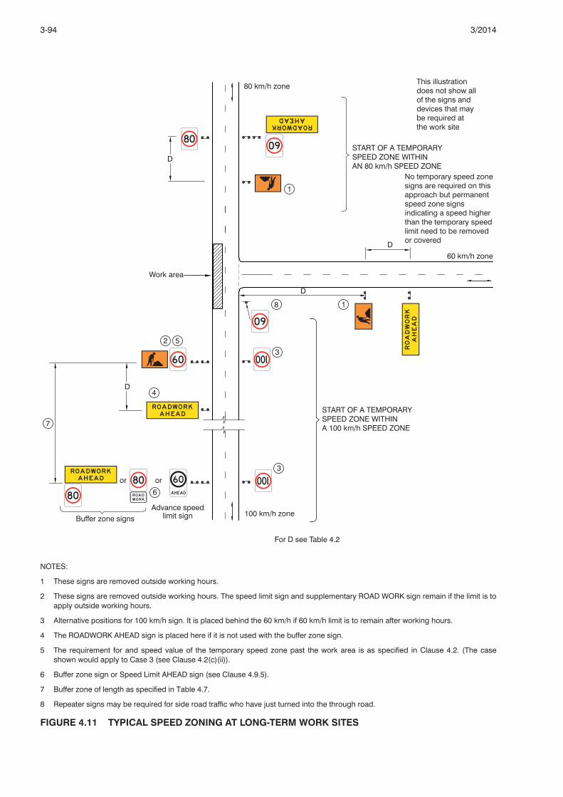
NOTES:
1 These signs are removed outside working hours.
2 These signs are removed outside working hours. The speed limit sign and supplementary ROAD WORK sign remain if the limit is toapply outside working hours.
3 Alternative positions for 100 km/h sign. It is placed behind the 60 km/h if 60 km/h limit is to remain after working hours.
4 The ROADWORK AHEAD sign is placed here if it is not used with the buffer zone sign.
5 The requirement for and speed value of the temporary speed zone past the work area is as specified in Clause 4.2. (The caseshown would apply to Case 3 (see Clause 4.2(c)(ii)).
6 Buffer zone sign or Speed Limit AHEAD sign (see Clause 4.9.5).
7 Buffer zone of length as specified in Table 4.7.
8 Repeater signs may be required for side road traffic who have just turned into the through road.
FIGURE 4.11 TYPICAL SPEED ZONING AT LONG-TERM WORK SITES
3-94 3/2014

4.10 TRAFFIC CONTROLLERS
4.10.1 ApplicationSituations requiring control of traffic by traffic controllers are listed in Table 4.8.
TABLE 4.8 USE OF TRAFFIC CONTROLLERS
Situation Purpose of control
Bituminous surfacing under traffic To slow down, stop or direct traffic, as appropriate
Single-lane operation To restrict traffic flow to a single direction at any time and toalternate the direction of flow as necessary
Low-speed operation To warn and slow down traffic at locations where a temporaryspeed limit would be required but has not been installed
Temporary total closures, e.g. blasting works To stop traffic to inform drivers of the likely delay, and to holdtraffic until it is safe to proceed
Plant crossings To stop traffic as needed to avoid conflict with plant crossing orentering the roadway at an established plant crossing point
Limited sight distance within work site To slow down and warn motorists of a hidden or partiallyhidden hazard ahead
Emergency situations To stop and direct traffic as necessary
4.10.2 EquipmentA STOP/SLOW hand bat (R6-8/T7-1) (see Clause 3.5.2) shall be used, except when a boom barrier isused. For night-time operations, an illuminated wand should be used in conjunction with the bat. If aboom barrier is used, the STOP sign, R6-8, may be mounted on the boom.
The Traffic Controller/PREPARE TO STOP sign (T1-Q05) shall be placed at least 2D (where value of Dis the greater value of the range of dimensions shown in Table 4.2) in advance of the traffic controller.
A temporary hazard marker (T5-5) (see Clause 3.9.3), a temporary barrier or a boom barrier may beused to assist the traffic controller.
Portable two-way radios or similar means shall be used for communication between traffic controllers(except in the vicinity of blasting works) if they are unable to communicate by sight.
Traffic controllers shall wear high visibility clothing as specified in the Traffic Controller AccreditationScheme Approved Procedure (TCASAP).
Four cones at 4 m spacing should be installed on the centreline in advance of the Traffic Controller position, except where the Traffic Controller is positioned past a merge taper.
4.10.3 Sight distanceTraffic controllers shall not be located in positions where the sight distance is less than 2D (where thevalue of D is the greater value of the range of dimensions shown in Table 4.2) metres between thecontroller and oncoming traffic.
See Clause 4.10.2 for positioning of the Traffic Controller/PREPARE TO STOP sign (T1-Q05).
4.10.4 Control of approach speedApproach speeds to locations where traffic controllers are operating shall be controlled to 60 km/h orless by means of appropriate advance signs and devices including a temporary speed zone.
4.10.5 Period of dutyTraffic controllers shall be relieved from their duty after not more than 2 hours for a period of rest orother duties of at least 15 minutes.
4.10.6 Traffic controller competencyRefer to Clause 1.4.3 and Appendix J.
3-953/2014
Amdt.1 05/14

4.11 PORTABLE TRAFFIC SIGNALS
4.11.1 GeneralPortable signals (see Clause 3.5.4(a)) are intended only for traffic control applications of a relativelyshort duration. For sites where work will continue for a longer period without the location of the workarea changing, consideration should be given to the installation of temporary, rather than portable,traffic signals (see Clause 3.5.4(b)).
Portable traffic signals are intended to be applied primarily to shuttle control, i.e. where a portion of theroadway is closed so that a single lane has to be used alternately by traffic from opposite directions.Traffic capacities for single lane sections of various lengths under shuttle control are given in Clause4.13.1.
Signals may also be adapted for machinery crossing application.
Typical use of portable traffic signals is shown in Figure 4.12.
4.11.2 OperationThe following gives guidelines for the three modes of operation of portable traffic signals:
(a) Vehicle-actuated operation
Vehicle-actuated operation allows the signals to operate automatically in response to vehicledemands.
Vehicle-actuated operation is the preferred mode and should be used wherever possible underthe following conditions:
(i) Traffic flow is not hindered by operations at the work area.
(ii) Traffic control is required to operate after working hours.
(b) Fixed-time operation
Fixed-time operation does not respond to vehicle demand. Cycle times are a fixed length. Fixed-time operation is applicable to the following conditions:
(i) Vehicle-actuated control is not possible.
(ii) The flow of traffic on all approaches is relatively constant and is not hindered by operations atthe work area.
(iii) Traffic control is required to operate after working hours.
Failure of vehicle detectors in a vehicle-actuated system will usually cause the system to default tofixed-time operation.
(c) Manual operation
Manual operation allows operation of the signals by a traffic controller and is applicable to thefollowing conditions:
(i) Flow of traffic on each approach is variable and may be hindered from time to time byoperations in the work area.
(ii) A detector fails during the use of the vehicle-actuated mode and the fixed-time mode is notappropriate.
(iii) Traffic must be kept out of the work area for an extended period, e.g. during blasting, primingor full width sealing.
4.11.3 Approach conditions and speedSight distance on the approach to traffic signals shall be a minimum of 150 m to the primary signalface. A roadworks speed limit no higher than 60 km/h shall be imposed if the signals would otherwisebe in a higher speed limit zone.
4.11.4 Performance monitoringIrrespective of the form of operation, signals shall be monitored to ensure that they are operating safelyand effectively and do not cause unnecessary delays to traffic.
3-96 3/2014

NOTES:
1 A speed zone may be required, see Clause 4.9.3.
2 End-of-zone signs would also be required at the departure end of the work site.
FIGURE 4.12 TYPICAL USE OF PORTABLE TRAFFIC SIGNALS
3-973/2014

4.12 PILOT VEHICLEA pilot vehicle may be used to guide traffic through a work site. This form of assistance to trafficmanagement may be required where -
(a) part of the length of the work site is out of view of the supervisor, work gang and the trafficcontroller;
(b) the hazard to workers described in Clause 4.2(e) requires the traffic speed to be reduced to lessthan 40 km/h;
(c) the traffic speed is required to be kept low to minimise damage to the works; or
(d) traffic needs to follow a particular path through the site which may not be obvious unless a pilotvehicle is used.
The minimum identification of a pilot vehicle shall be a vehicle mounted warning device (see Clause3.12.1) together with T6-Q09, which is attached to the rear of the vehicle. Traffic should be instructed tofollow and not to pass the pilot vehicle. The PILOT VEHICLE IN USE (T1-Q13) sign shall be installed aminimum of D in advance of the location where the pilot vehicle operates (see Appendix I).
4.13 MAINTAINING TRAFFIC FLOW
4.13.1 Length of single-lane operation under reversible flowOn two-way roads, two-way flow should be maintained wherever possible. This may necessitate theconstruction of a side track or detour. However, where this is not possible traffic may be restricted toone lane over short lengths, preferably not longer than indicated in Table 4.9, for short periods of time.Additional guidance on maintaining suitable traffic operations is provided in TRUM Note 7.9.
In general, where traffic flows are within the recommended limits shown in Table 4.9, single-laneoperation requires active control by traffic controllers or by portable or temporary fixed traffic signals.The selection of the appropriate method of control requires consideration of -
(a) traffic volumes;
(b) duration of work;
(c) site conditions and layout; and
(d) personnel available
TABLE 4.9 DESIRABLE MAXIMUM LENGTH OF SINGLE-LANE OPERATION UNDERREVERSIBLE FLOW
Traffic volume (both directions) Length of single lane sectionVehicles per hour m
800 70
700 100
600 150
500 250
300 600
< 300 800
NOTES: 1. This length is to be taken as the distance between the traffic controller or traffic signal positions for each traffic direction.2. These desirable maximum lengths for single lane operation may be increased on Transport and Main Roads projects in
accordance with the contractual requirements of MRTS02.
Where drivers have a clear view of the work area and the opposing approach for a distance greaterthan 150 m in a 60 km/h or lower speed zone; or greater than 250 m elsewhere, beyond the work area,controls may be modified as follows:
(i) For traffic volumes 40 vph or less and posted speed limit during roadworks of 70 km/h or less,where the length of a single lane does not exceed 60 m - traffic control may not be required (seealso Clause 4.13.5).
3-98 3/2014

(ii) Where the length of a single lane is less than 100 m and other requirements of Clause 3.5.3(a) aremet - control may be exercised by the use of a GIVE WAY and ONE LANE sign assembly. This isnot recommended where the posted speed limit during roadworks exceeds 80 km/h. Active singlelane control is preferred.
4.13.2 Number of lanes for each direction of flowOn multilane roadways in peak periods, the normal number of traffic lanes in the direction of major flowshould be available. Table 4.10 gives guidance on the number of lanes required at short term worksand long term works of up to 7 days duration. For longer term works, precise calculation of capacitymay be necessary to ensure that traffic demand can be met. Additional guidance on maintainingsuitable traffic operations is provided in TRUM Note 7.9.
TABLE 4.10 DESIRABLE NUMBER OF LANES FOR EACH DIRECTION
Mid-block Within 200 m of an intersection Desirable number of lanes(upstream or downstream) for direction considered
Vehicles per hour, one direction Vehicles per hour, one direction
Up to 1000 Up to 500* 1
1100 to 2000 600 to 1000 2
2100 to 3000 1100 to 1500 3
3100 to 4000 1600 to 2000 4
* Right turns out of the single lane may need to be prohibited depending on the proportion of heavy vehicles and the volume ofopposing traffic.
NOTE: Volumes shown in the Table may need to be reduced by the amount shown if the following apply:
(a) Pavement surface is rough or unsealed - reduce traffic volume by 30%.
(b) Horizontal geometry through the restriction is reduced to a speed value of less than 40 km/h - reduce volume by 50%.
(c) Volume of heavy vehicles exceeds 10 percent -
(i) downward, level or easy upgrade - reduce traffic volume by 20%; and
(ii) sustained upgrades >5% - reduce traffic volume by 40%.
Where the requirements of Table 4.10 cannot be complied with, parking bans or lane reversal or bothmay be necessary. If in extreme circumstances one direction of travel must be detoured, safetyarrangements should be planned in advance so that conditions can be improved on the detour routeprior to opening. In congested built-up areas many works, especially mobile and maintenance works,are necessarily confined to nights and weekends.
Right turns may need to be banned at appropriate locations in the work site to maintain traffic flow.Allowance might also be required for the effects on traffic flow of rough or unsealed surfaces, oraltered geometry which markedly reduces speed.
Lane reversal requires special consideration of, and provision for pedestrians where the traffic flow isopposite to normal expectations, especially where traffic is diverted to the opposite side of a median.This should be avoided if at all possible, but failing that, every effort should be made to redirectpedestrian movements to locations beyond the work area or at least to marked crossings at signalisedintersections (see Clause 4.14.8).
4.13.3 Lane widthsThe minimum lane width to be provided through or past a work site shall be as per Table 4.11, with thefollowing exceptions:
(a) Curve widening of 0.5 m per lane shall be applied to curves of radius between 100 m and 250 m.
(b) Curve widening on curves of less than 100 m radius shall, in addition to Item (a), take into accountthe swept path of long vehicles.
(c) Where lanes on the approach to the work site are less than 3.0 m in width, the approach lanewidth may be adopted. This shall not however, apply to curves of radius 250 m or less, nor tolocations where there are fixed vertical obstructions such as fences or safety barriers within 300mm of the edge of the lane on one or both sides.
3-993/2014

(d) Two-way roadway width on residential streets may be reduced to 5.5 m, see Clause 4.13.5(a).
TABLE 4.11 MINIMUM LANE WIDTHS
Posted speed limit during roadworks, Minimum lane width,km/h m
60 or less 3.0
70 to 90 3.2
greater than 90 3.4
Note: Temporary lane widths are not to be greater than existing lane widths.
4.13.4 Edge clearancesClearance between edge of traffic lane and delineating devices or road safety barrier system shall beas below. This clearance shall be measured to the traffic-side edge of delineating devices or barrier.This edge shall also be the line from which clearances to the work area are measured for the purposeof determining treatments in Clause 4.2.
(a) Edge of traffic lane to line of traffic cones, bollards or longitudinal channelising barricades -
(i) posted speed limit during roadworks up to 60 km/h - 0.5 m; and
(ii) posted speed limit during roadworks above 60 km/h - 1.0 m.
(b) Edge of traffic lane to roadworks delineators or temporary hazard markers - 1.0 m.
(c) Edge of traffic lane to road safety barrier system -
(i) posted speed limit during roadworks 40 km/h or less - 0.3 m;
(ii) posted speed limit during roadworks 50 to 80 km/h - 0.5 m; and
(iii) posted speed limit during roadworks greater than 80 km/h - 1.0 m.
In the absence of marked lines on the pavement these clearances shall be added to the nominal lanewidths provided according to Clause 4.13.3.
If the edge of the traffic lane is kerbed, delineation devices shall be placed 0.3 to 0.5 m clear behindthe face of kerb.
NOTE: Road safety barriers should not be placed behind kerbs on roads with a speed limit of 80 km/h and above.
Containment fences marking the limit of work area shall be placed as specified in Clause 4.2.
Clearances adjacent to excavations are given in Appendix E.
4.13.5 Work in residential streetsWhere work is in residential streets, the following should be observed:
(a) If the remaining clear roadway width is 5.5 m or more, two-way operation should be maintained. If5.5 m cannot be maintained, the width should be reduced to a maximum of 3.5 m to ensurevehicles operate in single file under shuttle working conditions. The need to accommodate theswept path of large vehicles negotiating a work site should also be considered.
(b) The normal method of traffic operation for shuttle working will be a natural ‘give and take’,provided that there is clear visibility past the work area and beyond it for at least 75 m or to theend of the roadway if less than 75 m away and the length of shuttle lane does not exceed 60 m.
If these conditions cannot be maintained active traffic control will be required i.e. trafficcontrollers, or temporary or portable traffic signals.
(c) The length of the approach taper should be approximately 15 m where two-way operation ismaintained. Where shuttle working under natural give and take is in operation, the taper should beat 45 degrees on both the approach and departure sides of the works.
(d) The need for advance warning should be determined in accordance with Clause 4.7.1.
3-100 3/2014

4.14 DETOURS, SIDE-TRACKS AND CROSSOVERS
4.14.1 GeneralIn situations where it becomes impracticable to accommodate traffic within the existing roadway, oneof the following forms of traffic detour should be considered:
(a) Side-tracks
A temporary roadway may be constructed beside or near the existing roadway, usually within thesame road reserve. It may cater for one or both directions of travel.
(b) Detours via existing roads
Traffic in one or both directions may be detoured via existing roads suitably located to carry trafficaround the work area.
(c) Crossovers
Part of a divided road is converted to a two-way roadway by closing one roadway andconstructing temporary crossovers to transfer traffic in that direction to the other roadway.
(d) Detours for heavy or over-dimensional vehicles
See Clause 4.14.10.
Where used, the above forms of detour shall be provided in accordance with the requirements andrecommendations in the clauses below. Typical signing arrangements are illustrated in Figures 4.13,4.14 and 4.15.
4.14.2 Surface conditionPavement and pavement surface condition shall be appropriate to and adequate for the type andvolume of traffic using the facility and its location. The following requirements shall be observed:
(a) Temporary pavements shall have sufficient structural strength to carry the anticipated heavyvehicle traffic.
(b) Pavements on detours via existing roads shall be checked to ensure that they are structurallyadequate to carry the increased volumes and loads.
(c) Pavements on detours and side-tracks shall be monitored to ensure that any indications ofimpending pavement failure are dealt with promptly.
4.14.3 Alignment, width and capacityFor detours which will be in use for periods in excess of 14 days, the lane width and design speedshould match, as nearly as practicable, those of the approach road.
Every attempt should be made to maintain capacity on roads which normally run close to theircapacity, particularly during peak hours in built-up areas. In addition to maintaining the requirednumber of lanes in accordance with Clause 4.13.2, note should be taken of the effect on capacity of -
(a) traffic lanes less than 3.0 m in width; and
(b) unsealed or rough surfaces.
Either condition could lead to lane capacity being reduced by as much as 50 percent.
Works may need to be scheduled so that peak hour capacities are maintained.
3-1013/2014
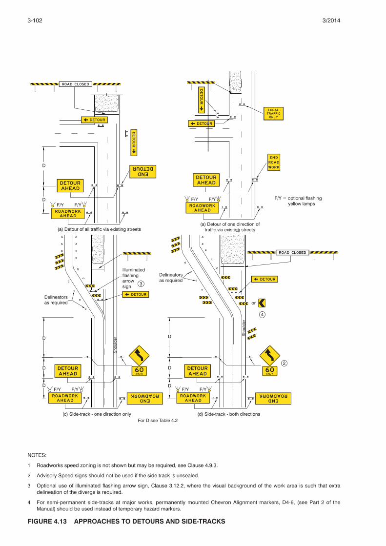
NOTES:
1 Roadworks speed zoning is not shown but may be required, see Clause 4.9.3.
2 Advisory Speed signs should not be used if the side track is unsealed.
3 Optional use of illuminated flashing arrow sign, Clause 3.12.2, where the visual background of the work area is such that extradelineation of the diverge is required.
4 For semi-permanent side-tracks at major works, permanently mounted Chevron Alignment markers, D4-6, (see Part 2 of theManual) should be used instead of temporary hazard markers.
FIGURE 4.13 APPROACHES TO DETOURS AND SIDE-TRACKS
3-102 3/2014

NOTES:
1 A temporary speed zone for traffic safety purposes may be required (see Clause 4.9.3).
2 For semi-permanent side-tracks at major works, permanently mounted Chevron Alignment markers, D4-6, (see Part 2 of theManual) should be used instead of temporary hazard markers.
FIGURE 4.14 APPROACHES TO A CROSSOVER
3-1033/2014

4.14.4 Provision for pedestrians, bicycles, wheelchairs and public transportWhere there is a demand for use of the detour by pedestrians, cyclists or wheelchairs, facilities such asfootpaths, cycle tracks and sealed shoulders as appropriate to the demand and the safetyrequirements should be provided. Use of the signs and devices specified in Clause 3.14 may benecessary to guide pedestrians and to ensure their safety.
Where public transport stops need to be temporarily relocated on a detour, provision shall be made forsafe pedestrian access to the stop. Provision should also be made for the public transport vehicle tostop clear of moving traffic.
4.14.5 Access for local trafficProvision shall be made for local traffic to bypass barriers to gain access to properties within theclosed-off section of road. Gaps should be left in barriers in locations which will not encourage throughtraffic to use them either by mistake or intentionally, e.g. locating the gap to the far side of the roadwayand making it as small as practicable. The sign LOCAL TRAFFIC ONLY (G9-40-2) should be placedbeside the gap.
4.14.6 DelineationThe following are requirements and recommendations for delineation at side-tracks and detours:
(a) A side-track having the same standard of alignment, width and pavement surface as the approachroute, shall be delineated as for a permanent roadway in accordance with Part 2 of the Manual.
NOTE: Such a side-track represents the ideal and should be sought after for long-term sidetracks. It will rarely require roadworkssigning.
(b) Side-tracks where any of the factors in Item (a) are below the standard of the approach road, shallhave the following delineation:
(i) Delineators, red on the left side and white on the right, at the following spacing:
(A) Straights and curves greater than 200 m radius - 20 m spacing, in pairs.
(B) Curves up to 200 m radius - 6 m on outside of curve, 12 m on inside.
(C) On roads with volumes of 1500 vpd or less, spacings increased up to the following:
(1) Long flat straights - up to 100 m.
(2) Short and undulating straights - up to 50 m.
(3) Curves greater than 200 m radius - up to 25 m.
(ii) On sealed pavements the following linemarking:
(A) Dividing line, marking in accordance with Part 2 of the Manual, including barrier line wherewarranted.
(B) Edge lines at traffic volumes greater than 1500 vpd.
(iii) Temporary hazard markers at the beginning of the side-track if either it begins with a smallradius curve, or it could appear in some visibility conditions that the road does not diverge.
(c) At detours using existing roads or streets, upgrading of linemarking to that consistent with thevolume using the detour should be undertaken whenever the detour is likely to be in use for morethan three days.
(d) At crossovers, the temporary diversion through the median shall be delineated with traffic conesor bollards at 2 m spacing.
The temporary dividing line on the single open roadway shall be treated with extra delineation asappropriate. Depending on traffic volumes and speeds the following additional delineation should beconsidered:
(i) Conversion of the dividing line to double unbroken.
(ii) Reducing spacing of RRPMs to one half or one quarter of normal spacing.
(iii) Use of lane dividers (see Clause 3.9.5).
3-104 3/2014

4.14.7 Continuity of signing at a detourWhere a detour via existing roads is provided, signing of the detour at all changes of direction and atother locations where reassurance is needed shall be applied consistently throughout for eachdirection of travel. Signing arrangements should be checked to ensure that all detour signs areprominently displayed.
4.14.8 Reversed traffic directionWhere, at a detour or crossover, traffic is required to travel temporarily in the wrong direction, thefollowing safety measures should be considered:
(a) Intersections
Intersections should be checked and temporarily modified as necessary to ensure that crossingand turning movements can be made safely. Any movements needing to be temporarily bannedshould be adequately catered from elsewhere.
(b) Roadside hazards
Potential hazards resulting from the reversal of direction such as fixed roadside objects protectedin one direction only, and safety barrier and bridge parapet trailing ends which will becomeleading ends, should be risk assessed and remedial action taken accordingly.
(c) Pedestrian management
Where it is necessary to cater for pedestrians crossing a temporary two-way roadway at zebracrossings, uncontrolled mid-block crossing points or at intersections where there is traffic turningthrough a pedestrian crossing point, the following steps should be considered:
(i) Control of the point at which pedestrians cross by means of containment fences, and ifappropriate, pedestrian mazes.
(ii) People to patrol the site to assist pedestrians crossing the road.
(iii) Use of signs LOOK BOTH WAYS, TWO-WAY TRAFFIC (T8-5) (see Clause 3.14.5) to facepedestrians about to cross the road, as shown in Figure 4.15.
(d) Entering traffic
Use of signs LOOK BOTH WAYS, TWO-WAY TRAFFIC (T8-5) should also be considered at sideroad approaches to a temporary two-way roadway as shown in Figure 4.15 to warn enteringtraffic.
3-1053/2014

FIGURE 4.15 ‘LOOK BOTH WAYS’ SIGNS
4.14.9 Freeway exit closuresWhere a freeway exit is to be closed advice shall be provided -
(a) in advance of the previous exit if traffic is to be detoured by that exit; or
(b) in advance of the closed exit if traffic is to be detoured by the succeeding exit.
Advice shall take the form of black on yellow temporary signs mounted in conjunction with eachadvance and position sign for the relevant exit in Item (a) or (b) above, indicating the exit which isclosed and which alternative exit should be taken. The legend should as far as practicable be equal inlegibility to the legends on the associated permanent direction signs.
All necessary direction signs and detour signs shall be provided on the adjacent street system fordiverted traffic.
4.14.10 Detours for high and heavy vehiclesDetours for high or heavy vehicles will usually be required -
(a) if works on road or other factors have temporarily reduced the height clearance or load carryingcapacity of the original road; or
(b) if the route is a designated overdimensional load route on which overdimensional clearances havebeen temporarily reduced.
Signposting of a typical high vehicle detour is illustrated in Figure 4.16.
NOTE: A second physical over-height barrier may be required in the case shown in Figure 4.16, if the risk of collision is high or theconsequences especially severe, or both.
3-106 3/2014
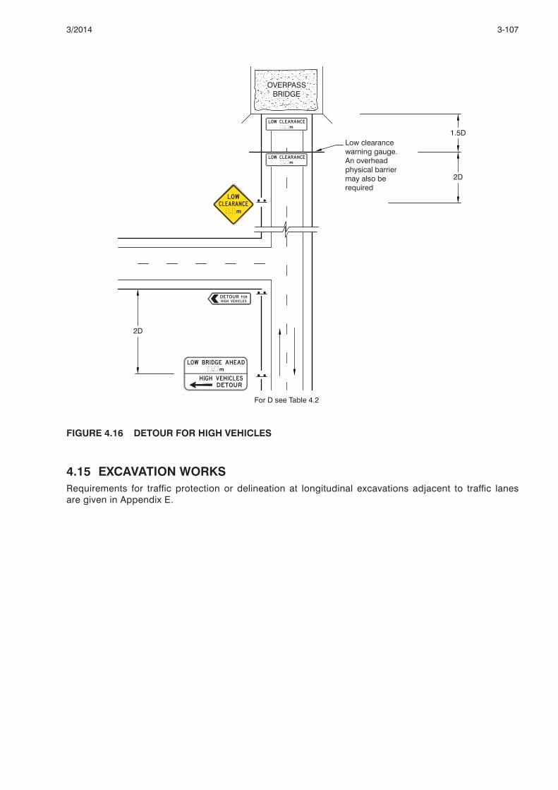
FIGURE 4.16 DETOUR FOR HIGH VEHICLES
4.15 EXCAVATION WORKSRequirements for traffic protection or delineation at longitudinal excavations adjacent to traffic lanesare given in Appendix E.
3-1073/2014

(Blank)
3-108 3/2014

SECTION 5. ARRANGEMENT DIAGRAMS FOR TRAFFIC GUIDANCE SCHEMES
5.1 SCOPEThis Section provides diagrams of example traffic guidance schemes which illustrate the application oftraffic control devices to various work site situations and circumstances. The diagrams, which indicatethe appropriate positions of the signs and devices required to guide traffic safely around, through orpast the work site, should cover most road work situations. Each diagram is accompanied by notes.
5.2 APPLICATIONThe traffic guidance schemes illustrated include examples of applications to short-term and long-termworks, and to all types of roads, e.g. multilane roadway and two-way roads.
Work site situations which are not specifically covered by the diagrams should be signed by adaptingthe most appropriate diagram according to the principles outlined in this Manual. If the traffic guidanceschemes illustrated do not adequately address all the site specific conditions and issues, then a sitespecific sketch for the traffic control must be developed.
No one standard arrangement of signs and devices can operate for every work site, or for differentoperations at a particular site. It may be necessary to vary warning signs and devices at a work site,not only from day to day, or from day to night operation, but also from hour to hour (see Clause 2.6.2).
Whenever it is necessary to undertake roadworks within an intersection, warning signs must be erectedon each of the approaches on which traffic is affected by the works (see Diagrams 19, 20, 33, 34, 35and Appendix F). It is also important to consider the needs of pedestrians (see Clause 3.14).
5.3 DIAGRAM SELECTIONTable 5.1 is the primary reference used to select the diagram appropriate to the prevailing or expectedwork site conditions.
In some cases Table 5.1 refers directly to an appropriate diagram which shows an example of the trafficcontrol devices and their arrangement. In other cases, reference is made to Tables 5.2 to 5.5 whichprovide a further selection guide to determine the appropriate diagram.
The situation diagrams il lustrate examples of the traff ic arrangements for various roadworkapplications. For bridgework, the ROADWORK AHEAD (T1-1) sign should be replaced with theBRIDGEWORK AHEAD (T1-2) sign.
The diagrams selected using this procedure should satisfy the requirements of safety and publicconvenience if consideration is given to the following factors:
(a) Duration of work.
(b) Type of work site.
(c) Width restricted.
(d) Lane configuration.
(e) Actual width available for traffic.
(f) Time of restriction.
(g) Traffic diversion options.
(h) Availability of personnel.
(j) Traffic volumes.
3-1093/2014

5.4 DIAGRAM SYMBOLSSymbols used in Diagrams 1 to 37 are as follows:
5.5 EXAMPLE DIAGRAMS
5.5.1 GeneralThe example traffic guidance scheme diagrams are divided into nine categories which are set outbelow together with a brief description of the type of work site covered by each example diagram.
Example diagrams have been included in this Part of the Manual and are numbered 1 to 37, some withmultiple options (A, B, etc.)
These example diagrams which conform with this Manual have been prepared based on the optionsavailable in this Part of the Manual and typically use multi-message sign arrangements.
They are example traffic guidance schemes and other possible traffic guidance scheme solutions maybe more appropriate for the given site conditions and work methods/practices to be adopted atspecific sites.
Thus an understanding of the underlying principles and options in this Part of the Manual is essentialwhen selecting and implementing a traffic guidance scheme.
(a) Short-term work
1A Short term - frequently changing: clear of traffic lanes - workers on foot
1B Short term - frequently changing: clear of traffic lanes - plant only
2 Short-term - full lane closure: residential street - low speed - 50 km/h maximum speed limit
3 Short term - part lane closure: two-way road - low speed
4 Short-term - full lane closure: two-way road
5 Short-term - traffic through work area: two-way road
6 Short-term - lane closure: work in centre lane - multilane undivided road
3-110 3/2014
ANTIGLARE SCREEN
BARRIER
DELINEATORS
MESH FENCING
RAISED RETROREFLECTIVEPAVEMENT MARKERS
SIGN, CAB-MOUNTED
SIGN, LOCATION
TEMPORARY HAZARD MARKER
SINGLE TEMPORARYHAZARD MARKER
TRAFFIC CONES
TRAFFIC CONTROLLER
TRAFFIC SIGNAL HEAD
TRAFFIC SIGNAL LOCATION
VEHICLE
WORK AREA
MULTI TEMPORARY HAZARDMARKER

7A Short-term - left lane closure: multilane divided road
7B Short-term - left lane closure: multilane undivided road
7C Short-term - median lane closure: multilane divided road
7D Short-term - median lane closure: multilane divided road
8 Short-term - occupation of centre of roadway: two-way road
9 Short-term - temporary closure of roadway: multilane divided road
(b) Lane and roadway closures
10 Shoulder closure - two-way road
11 Short-term - part lane closure: two-way road
12 Lane closure: two-way road or bridge
13 Long-term lane closure: two-way road
14 Long-term lane closure: multilane divided road
15 Long-term lane closure of 2 outer lanes: multilane undivided road
16 Long-term - closure of 2 central lanes: multilane undivided road
17 Short-term - closure of one side: multilane undivided road - low speed
18 Short-term - closure of one side: multilane undivided road - high speed
19 Lane closure: major roundabout
20 Part lane closure: minor roundabout
21 Haul road crossing: two-way road
22 Road closed: blasting
(c) Detours and sidetracks
23 High vehicle detour: two-way road
24 Long-term - heavy vehicle detour: two-way road
25 One lane sidetrack: two-way road
26 Two-way sidetrack: two-way road
27 Sidetrack crossing median (crossover): multilane, divided road
28 One direction detour: two-way road
29 Detour all traffic: two-way road
30 Exit closure: multilane, one-way roadway
(d) Special work situations
31 Road temporarily closed: two-way road
32 Linemarking: all roads
33 Kerbside work: intersection of a two minor roads
34 Kerbside work: intersection of a minor and a major road
35 Kerbside work: intersection of two major roads
36 Work occupying the full width of a footpath
37 Closure of two outer lanes: one direction - multilane road
3-1113/2014

5.5.2 Example diagram selection tables
Table 5.1 EXAMPLE DIAGRAM SELECTION FOR ROADWORKS SITUATIONS
Diagram Selection/Road Type
Description of Works 2 way Multi-lane Multi-lane dividedundivided (freeway type
operations)
Closure of footpath 36 36 –
Closure of shoulder Table 5.2 10 10
Closure of traffic lane(s) Table 5.3 Table 5.5 Table 5.5
Temporary road closure Table 5.4 22 9
Work under traffic 5 – –
Bridgeworks Select the appropriate description and Diagram from this table and alsorefer to Clause 5.2
Detours
– High vehicle detour 23 Adapt 23 to multilane case (See Notes 1 and 5).
– Heavy vehicle detour 24 Adapt 24 to multilane case (See Notes 2 and 5).
– One lane sidetrack 25 Adapt 25 to multilane case (See Note 3).
– Two-lane sidetrack 26 Adapt 26 to multilane case (See Note 3).
– Sidetrack crossing median – – 27
– One direction detour 28 Adapt 28 to multi-lane case (See Note 2) –
– All traffic detour 29 Adapt 29 to multi-lane case (See Note 2) –
– Exit ramp closure – – 30
Miscellaneous situations
– Frequently changing work area 1A, 1B 1A, 1B
– Blasting 22 22
– Haul road crossing 21 –
– Pavement marking 32 Adapt 32 to multilane case
– Short-term kerbside work at an 33 34 and 35intersection in a built-up area
– Roundabouts 20 19
3-112 3/2014

Table 5.2 CLOSURE OF SHOULDER - TWO-WAY ROAD
NOTE:
1. A minor pavement encroachment is one that leaves at least the following formed width of trafficable road -
• Approach speed less than 60 km/h - 5.5 m
• Approach speed 60 km/h or greater - 6 m
Consideration should be given to a lane closure or road widening to allow two-way traffic, when large combination vehicles arepresent.
Duration AADT. Pavement Lighting Method Diagramof Works Veh/Day Encroachment (1) Conditions of Control No.
day/night' usually not needed 1
Minorday/night
0-400
NoneSHORT usuallyTERM not 3, 10
WORKS day/night needed
NoneOver400
Minor day/night usually not needed 311
Minor
0-400usually
None day/night not 10LONG neededTERM
WORKS
NoneOver400
Minor day/night usually not needed 10
3-1133/2014

Table 5.3 CLOSURE OF TRAFFIC LANE - TWO-WAY ROAD
NOTE:
1. Formed width of the roadway (sealed or unsealed). This width is the minimum lane width to be provided (see Clause 4.13.3).
Duration AADT Available Other Considerations Method of Control Diagram No.of Works Veh/Day Width (m) (1)
N/a 3.5, or 5.5 Residential adequate not needed 2and over street,
visibility inadequate Traffic Controllers 4betweenends ofclosure
0-150 3.0-5.9 Visibility inadequate Traffic Controllers 4betweenends adequate GIVE WAY sign 12of closure
6.0 and over not usually needed 8, 11
150-1500 3.0-5.9 Traffic Controllers 4
6.0 and over not usually needed 8, 11
1500-3000 3.0-5.9Controllers-consider 4
6.0 and over Available width No use of boom barriersfully sealed?
Yes not usually needed 11(1)
over 3000 6.0 and over Available width Yesfully sealed?
No Traffic 4Controllers
3.0-5.9
0-150 3.0-5.9 Visibility inadequate Temporary Traffic 12between signalsends adequate GIVE WAY sign 12of closure
6.0 and over not usually needed 13
150-1500 3.0-5.9 Temporary Traffic 12signals
6.0 and over not usually needed 13
over 1500 6.0 and over Available width Yesfully sealed?
No Temporary Traffic 12Signals
3.0-5.9
3-114 3/2014
LON
G-T
ER
M W
OR
KS
SH
OR
T-TE
RM
WO
RK
S

Table 5.4 TEMPORARY ROAD CLOSURE - TWO-WAY ROAD
Table 5.5 MULTILANE ROADS
NOTE: For detours refer Table 5.1.
Configuration Duration of Works No. of Lanes Diagram No.
Short-term 4 to 8 7A, 7B, 7C, 7D
One Lane ClosedLong-term 4 to 8 14
Two Lanes Closed Short-term 4 6
– Equal No. of Lanes in Long-term 6 or 8 15 – 2 outerboth directions lanes closed
16 – 2 centrelanes closed
Two Lanes Closed
– Unbalanced flows Short-term 4 to 8 37
Short-term 4 17 - low speed18 - high speed
One Side Closed
Long-term 4 27
Temporary road closure All 3 9
Duration Nature of Works AADT Description Diagram No.of Works
Blasting or where unsafe to All Complete Road Closure 22Day Only traverse works during closure
Elsewhere All 22, 31
Night Work area to be made trafficable and barriers removed by nightfall. Elsewhere, and where analternative route is available (see Diagram 29).
3-1153/2014

5.5.3 Common tables referred to in the example diagram notesTables 4.2, 4.6 and 4.7 are reproduced for ease of reference. For tolerances regarding the placementof signs, refer to Clause 4.1.6.
Value of Dimension D (Table 4.2)
NOTE: The Traffic Controller/PREPARE TO STOP sign (T1-Q05) shall be placed at least 2D (where value of D is the greater value of therange of dimensions shown in the Table) in advance of the traffic controller.
Recommended Taper Length (Table 4.6)
Permanent postedspeed,km/h
Recommended taper length, m
Traffic control at beginning oftaper
Lateral shift taper Merge taper
40 or less
50
60
70
80
90
100
Greater than 100
15
15
30
30
30
30
30
30
5
15
30
60 - 80
60 - 80
60 - 80
60 - 80
60 - 80
15
30
60
120 - 160
120 - 160
120 - 160
120 - 160
120 - 160
Posted speed limit (prior to roadworks)km/h
Dimension Dm
40 or less 5 to 10
50 10 to 15
60 15 to 45
70,80 60 to 80
90,100 80 to 100
110 100 to 120
3-116 3/2014

Guide to the Selection of Roadworks Speed Limits (Table 4.7)
* Mandatory requirements are specified for or relate to these items in the Clauses referenced.
Speed limitkm/h
Selection criteria Notes on application
<40 Workers safety:
• Unusually high level of hazard for workerson foot within 1.2 m of moving traffic.
Traffic safety:
• It is impracticable to separatepedestrians or cyclists from vehiculartraffic in the work area.
See Clause 4.2(e).
40 Workers safety:
• Workers on foot are working within 1.2 mof traffic with no intervening physicalprotection (see Clause 4.2(c)(iii))*.
Traffic safety:
• There would be structural danger tobridges at higher speeds.
This limit is specified as an option for meetingworkplace safety requirements set out in Clause 4.2. It will not be observed if conditions do not appear todrivers to warrant it. Steps should always be taken inthe first instance to avoid conditions requiring thislimit.
For worker safety, zone length is specified as 1 kmmaximum. There is a requirement for workers to bevisible.*
60 Workers safety:
Workers on foot or operating plant are within 3 m of the trafficable area with no interveningphysical barrier (see Clause 4.2(c)(ii))*.
• A traffic controller is being used (seeClause 4.2(d))*.
• In advance of portable or temporary trafficsignals (see Clause 4.11.3)*.
• Dust or smoke may reduce visibility.
Traffic safety:
• Traffic is subjected to a reduced standardalignment due to the works.
• The pavement surface has been degraded.
• A bituminous seal has just been laid.
This limit is specified as an option for meetingworkplace safety requirements set out in Clause 4.2. Itis also relevant within higher speed zones where thereis significant temporary reduction in pavement surfacecondition, traffic path alignment or other travelconditions caused by the works.
The 60 km/h zone length is specified as 150 mminimum.* No maximum length is specified.
60 buffer(if required)
Used on approach to 40 km/h zone whereapproach speeds would otherwise be 80 km/hor greater (see Clause 4.9.5).
A buffer zone in advance of a 40 km/h road work zoneshould be 150 m minimum length. If required, due tosite constraints, the length of this advance warning(buffer zone) may be increased up to 300 mmaximum.
80 Workers safety:
• Workers on foot or operating plant arebetween 3 m and 6 m of the trafficablearea with no intervening physical barrier(see Clause 4.2(b))*.
Traffic safety:
• The need for a lower limit does not exist,but there is some disturbance to alignmentor pavement surface which makesunrestricted speeds undesirable on trafficsafety grounds.
This limit should not be imposed on traffic safetygrounds if unrestricted speeds through the work sitecan be tolerated at the prevailing level of driverbehaviour.
Long lengths of 80 km/h temporary speed zone onroads or freeways in open road areas will not beobserved if there are no workers or plant in evidence,or they are behind a physical barrier, and there isrelatively little reduction in travelling conditions evidentas a result of the works.
The 80 km/h zone length is recommended as 500 mminimum.
80 buffer(if required)
May be used to give advance warning of a 60 km/h zone where the posted speed is 100 km/h or greater (see Clause 4.9.5).
A buffer zone in advance of a 60 km/h roadwork zoneshould be 300 m minimum length.* If required, due tosite constraints, the length of this advance warning(buffer zone) may be increased up to 500 mmaximum.
3-1173/2014

EXAMPLE
5.5.4 Example diagrams 1A to 37
DIAGRAM 1A SHORT TERM - FREQUENTLY CHANGING: CLEAR OF TRAFFIC LANES - WORKERSON FOOT
3-118 3/2014

NOTES TO DIAGRAM 1A:
1. Frequently changing work area involving workers on foot with or without machinery on shoulders(see Clauses 4.3.4 and 4.3.5). Job examples - grass mowing, shoulder work, table drain clearing.Advance warning signs may be omitted if the sight distance exceeds 150 m in a 60 km/h or lowerzone, or 250 m elsewhere and a vehicle mounted warning device is displayed.
2. Where the shoulder material is soft or is to remain temporarily on the pavement, then theappropriate sign Slippery, Loose Stones, SOFT EDGES, etc should be shown a minimum distance2D (see Table 4.2) metres ahead of the hazard (see Clause 4.7.4). Where workers will be working onthe shoulder the Workers (symbolic) sign should be repeated in this location. Workers (symbolic)signs shall be used when workers are actually working.
3. Temporary speed zone to meet workplace or traffic safety requirements (see Clause 4.2 and Clause4.9). Remove when workers have left the work area.
4. Consider the need for cones along the edge of the pavement in accordance with Table 3.7.
5. The distance D for sign spacing is given in Table 4.2.
6. Refer to Clauses 4.3.3 and 4.3.4.
7. For works on unsealed roads see Clause 4.5.
8. Consider use of ROADWORK 1 km Ahead or ROADWORK 500 m Ahead signs in advance of thetaper at the work site for approach speeds of 90 km/h or greater, especially when the work siterequires a reduction in speed of 40 km/h or more see Clause 4.7.2.
9. For high speed road, additional signs to control vehicle approach speeds will be required.
3-1193/2014

EXAMPLE
DIAGRAM 1B SHORT TERM - FREQUENTLY CHANGING: CLEAR OF TRAFFIC LANES - PLANTONLY
3-120 3/2014

NOTES TO DIAGRAM 1B:
1. Frequently changing work area involving machinery running on shoulders (see Clauses 4.3.4 and4.3.5). Job examples - grass mowing, shoulder grading, table drain clearing. Advance warningsigns may be omitted if the sight distance exceeds 150 m in a 60 km/h or lower zone, or 250 melsewhere and a vehicle mounted warning device is displayed and no windrow is present near thepavement edge.
2. Where a shoulder is being graded, and if (for example) the shoulder material is soft or is to remaintemporarily on the pavement, then the appropriate sign Slippery, Loose Stones, SOFT EDGES, etcshould be shown a minimum distance 2D (see Table 4.2) metres ahead of the hazard. Whereworkers will be working on the shoulder the Workers (symbolic) sign should be repeated in thislocation. Workers (symbolic) signs shall be used when workers are actually working.
3. Temporary speed zone to meet workplace or traffic safety requirements (see Clauses 4.2 and 4.9).Remove when workers have left the work area.
4. The distance D for sign spacing is given in Table 4.2.
5. On sealed roads with traffic volumes less than 1500 vpd, where sight distance to the vehicle-mounted warning device is greater than 250 m in both directions, the distance between signs at thelimits of work may be increased to 10 km. Where this sight distance is not available, an additionalsign e.g. GRADER Ahead must be placed in advance of work to warn motorists (Clause 4.3.5).
6. For works on unsealed roads see Clause 4.5.
7. For high speed road, additional signs to control vehicle approach speeds will be required.
3-1213/2014

EXAMPLE
DIAGRAM 2 SHORT-TERM - FULL LANE CLOSURE: RESIDENTIAL STREET - LOW SPEED - 50 km/hMAXIMUM SPEED LIMIT
3-122 3/2014

NOTES TO DIAGRAM 2:
1. If the remaining clear roadway width is 5.5 m or more, two-way operation should be maintained. If5.5 m cannot be maintained, the width should be reduced to no more than 3.5 m (see Clause4.13.5) to ensure vehicles operate in single file under shuttle working conditions.
2. The Workers (symbolic) sign shall be removed when workers have left the area or are no longervisible to traffic. Placement of the sign should be in accordance with Clause 4.7.4.
3. Direct control of traffic may not be required if there is clear visibility of and beyond the work area for75 m, and the length of shuttle lane does not exceed 60 m (see Clause 4.13.5(b)). If theseconditions cannot be maintained some form of traffic control will be required.
4. Refer to Table 4.6 for recommended taper lengths and Clause 4.13.5(c) for work in residentialstreets.
5. One T5-Q02 (or T5-5) sign shall be placed within the taper area (refer Clause 3.9.3). If the lateralshift is more than 2 m consider the need for extra T5-Q02 (or T5-5) signs.
3-1233/2014

EXAMPLE
DIAGRAM 3 SHORT TERM - PART LANE CLOSURE: TWO-WAY ROAD - LOW SPEED
3-124 3/2014

NOTES TO DIAGRAM 3:
1. The minimum lane width shall be 3.0 m (see Clause 4.13.3) and the edge clearance shall be asdetermined in Clause 4.13.4. Where this remaining width is insufficient for a lane of traffic andvehicles need to cross the centreline to travel around the work area, Diagram 11 should be used.Where traffic controllers are used to control traffic, use Diagram 4.
2. The Workers (symbolic) sign shall be removed when workers have left the area or are no longervisible to traffic. The sign shall be placed at a distance 2D from the taper for speed limit 60 km/h ormore (Clause 4.7.4).
3. Consider the need to prohibit parking along this kerb.
4. For short term, low impact works (built-up area) see Clause 4.4.
5. Refer to Table 4.6 for recommended taper lengths.
6. One T5-Q02 (or T5-5) sign shall be placed within the taper area (refer Clause 3.9.3). If the lateralshift is more than 2 m consider the need for extra T5-Q02 (or T5-5) signs.
3-1253/2014

EXAMPLE
DIAGRAM 4 SHORT-TERM - FULL LANE CLOSURE: TWO-WAY ROAD
3-126 3/2014

NOTES TO DIAGRAM 4:
1. The vehicle should be parked -
(a) so it does not unduly obstruct motorists' vision of the travelled path;
(b) to leave a clear escape path for workers; and
(c) where necessary, in advance of the work area to protect workers.
2. A Traffic Controller Ahead/PREPARE TO STOP sign may be required on the right-hand side of highvolume roads.
3. The minimum lane width including trafficable shoulder shall be 3.0 m (see Clause 4.13.3). Forwidths of 6 m or more, see Diagram 11. Where only one traffic controller is available, and hightraffic volumes or barrier lines make it necessary to direct traffic through the work area seeDiagram 5.
4. For traffic volumes of 40 vpd or less and posted speed during roadworks 70 km/h or less, wherethe length of single lane does not exceed 60 m, traffic control may not be required. Where therequirements of Clause 4.13.1 are met, the GIVE WAY and ONE WAY sign assembly may be used(see Diagram 12).
5. Temporary speed zone to meet workplace or traffic safety requirements (see Clause 4.2). Removewhen workers have left the work area or are no longer visible to traffic.
6. May be omitted if continuous operations are in progress and vehicle has a vehicle-mountedwarning device activated.
7. A maximum speed limit of 60 km/h shall be used (see Clause 4.10.4).
8. Consider use of ROADWORK 1 km Ahead or ROADWORK 500 m Ahead signs in advance of thetaper at the work site for approach speeds of 90 km/h or greater, especially when the work siterequires a reduction in speed of 40 km/h or more see Clause 4.7.2.
9. Advance warning (see Clause 4.9.5) shall be provided by a buffer zone comprising either:
(a) a Speed Limit AHEAD sign; or
(b) a speed zone (see Table 4.7 for length of speed zone).
10. For works on unsealed roads see Clause 4.5.
11. The distance D for sign spacing is given in Table 4.2.
12. Refer to Table 4.6 for recommended taper lengths.
13. Four cones installed on the centreline in advance of Traffic Controller position (see Clause 4.10.2).
14. This diagram has advance and departure speed signage for a 100 km/h speed zone. Appendix L(Clause L5) illustrates the typical options available for speed signage at roadworks sites for anumber of different speed environments. To use this example diagram for different speed zones,modify the advance and departure speed signage shown in this example diagram according tothe options illustrated in Appendix L.
3-1273/2014

EXAMPLE
DIAGRAM 5 SHORT-TERM - TRAFFIC THROUGH WORK AREA: TWO-WAY ROAD
3-128 3/2014

NOTES TO DIAGRAM 5:
1. The vehicle should be parked-
(a) so it does not unduly obstruct motorists' vision of the travelled path;
(b) to leave a clear escape path for workers; and
(c) where necessary, in advance of the work area to protect workers.
2. A Traffic Controller Ahead/PREPARE TO STOP sign may be duplicated on the right-hand side ofroads where the volume is 10 000 vpd or greater.
3. Work area should not extend beyond centreline.
4. Traffic controller stops and holds all traffic in obstructed lane then when work area is temporarilyclear, directs traffic to the left of the Temporary Hazard Marker and through the work area.
5. Traffic should not be held for longer than 5 min at any time.
6. This arrangement should be used where-
(a) the minimum lane width including trafficable shoulder shall be 3.0 m (see Clause 4.13.3);
(b) where only one traffic controller is available; and
(c) barrier lines are present.
7. For works on unsealed roads see Clause 4.5.
8. Consider the need for a temporary speed zone to meet workplace or traffic safety requirements(see Clause 4.2). Remove when workers have left the work area or are no longer visible to traffic.A maximum speed limit of 60 km/h shall be used (see Clause 4.10.4).
9. Consider use of ROADWORK 1 km Ahead or ROADWORK 500 m Ahead signs in advance of thetaper at the work site for approach speeds of 90 km/h or greater, especially when the work siterequires a reduction in speed of 40 km/h or more see Clause 4.7.2.
10. The distance D for sign spacing is given in Table 4.2.
11. Advance warning (see Clause 4.9.5) shall be provided by a buffer zone comprising either:
(a) a Speed Limit AHEAD sign; or
(b) a speed zone (see Table 4.7 for length of speed zone).
12. May be omitted if continuous operations are in progress and vehicle has a vehicle-mountedwarning device activated.
13. Four cones installed on the centreline in advance of Traffic Controller position (see Clause 4.10.2).
14. This diagram has advance and departure speed signage for a 100 km/h speed zone. Appendix L(Clause L5) illustrates the typical options available for speed signage at roadworks sites for anumber of different speed environments. To use this example diagram for different speed zones,modify the advance and departure speed signage shown in this example diagram according tothe options illustrated in Appendix L.
3-1293/2014

EXAMPLE
DIAGRAM 6 SHORT-TERM - LANE CLOSURE: WORK IN CENTRE LANE - MULTILANE UNDIVIDEDROAD
3-130 3/2014

NOTES TO DIAGRAM 6:
1. If traffic control is required, a Traffic Controller Ahead / PREPARE TO STOP sign is used 2D inadvance of the traffic controller.
2. A central traffic lane should not be closed in isolation.
3. The minimum lane width including trafficable shoulder shall be 3.0 m (see Clause 4.13.3).
4. The distance D for sign spacing is given in Table 4.2.
5. The vehicle should be parked-
(a) so it does not unduly obstruct motorists' vision of the travelled path;
(b) to leave a clear escape path for workers; and
(c) where necessary, in advance of the work area to protect workers.
6. Consider use of ROADWORK 1 km Ahead or ROADWORK 500 m Ahead signs in advance of thetaper at the work site for approach speeds of 90 km/h or greater, especially when the work siterequires a reduction in speed of 40 km/h or more see Clause 4.7.2.
7. Temporary speed zone to meet workplace or traffic safety requirements (see Clause 4.2). Removewhen workers have left the work area.
8. An illuminated flashing arrow shall be used where the traffic volume is 1500 vpd or greater and theposted speed in advance of the taper is 70 km/h or greater (see Clause 4.8.3).
9. Advance warning (see Clause 4.9.5) shall be provided by a buffer zone comprising either:
(a) a Speed Limit AHEAD sign; or
(b) a speed zone (see Table 4.7 for length of speed zone).
10. A manoeuvre requiring the left hand stream to shift laterally into the right hand stream is to bepreferred see Clause 4.8.2.
11. Refer to Table 4.6 for recommended taper lengths.
12. Traffic control may be omitted if not required.
13. The safety buffer may be increased to 100 m on multi-lane roads (see Clause 4.1.4(c)).
14. This diagram has advance and departure speed signage for a 100 km/h speed zone. Appendix L(Clause L5) illustrates the typical options available for speed signage at roadworks sites for anumber of different speed environments. To use this example diagram for different speed zones,modify the advance and departure speed signage shown in this example diagram according tothe options illustrated in Appendix L.
3-1313/2014

EXAMPLE
DIAGRAM 7A SHORT-TERM - LEFT LANE CLOSURE: MULTILANE DIVIDED ROAD
3-132 3/2014

NOTES TO DIAGRAM 7A:
1. Signs shall be duplicated on the right-hand side of a one-way roadway, where practicable. Thesesigns may be required for the multi-lane undivided road situation.
2. The vehicle should be parked-
(a) so it does not unduly obstruct motorists' vision of the travelled path;
(b) to leave a clear escape path for workers; and
(c) where necessary, in advance of the work area to protect workers.
3. An illuminated flashing arrow shall be used where the traffic volume is 1500 vpd or greater and theposted speed in advance of the taper is 70 km/h or greater (see Clause 4.8.3).
4. Consider use of ROADWORK 1 km Ahead or ROADWORK 500 m Ahead signs in advance of thetaper at the work site for approach speeds of 90 km/h or greater, especially when the work siterequires a reduction in speed of 40 km/h or more see (Clause 4.7.2).
5. The distance D for sign spacing is given in Table 4.2.
6. May be omitted if continuous operations are in progress and vehicle has a vehicle mountedwarning device activated.
7. Temporary speed zone to meet workplace or traffic safety requirements (see Clause 4.2). Removewhen workers have left the work area.
8. Advance warning (see Clause 4.9.5) shall be provided by a buffer zone comprising either:
(a) a Speed Limit AHEAD sign; or
(b) a speed zone (see Table 4.7 for length of speed zone).
9. For a median lane closure, a manoeuvre requiring the left hand stream to shift laterally into theright hand stream is to be preferred see Clause 4.8.2 and Diagram 7C.
10. Refer to Table 4.6 for recommended taper lengths.
11. The minimum lane width including trafficable shoulder shall be 3.0 m (see Clause 4.13.3).
12. On a multi-lane divided road, traffic travelling in the direction not affected by roadworks may notrequire signing.
13. The safety buffer may be increased to 100 m on multi-lane roads (see Clause 4.1.4(c)).
14. This diagram has advance and departure speed signage for a 100 km/h speed zone. Appendix L(Clause L5) illustrates the typical options available for speed signage at roadworks sites for anumber of different speed environments. To use this example diagram for different speed zones,modify the advance and departure speed signage shown in this example diagram according tothe options illustrated in Appendix L.
3-1333/2014

EXAMPLE
DIAGRAM 7B SHORT-TERM - LEFT LANE CLOSURE: MULTILANE UNDIVIDED ROAD
3-134 3/2014

NOTES TO DIAGRAM 7B:
1. Signs shall be duplicated on the right-hand side of a one-way roadway, where practicable. Thesesigns may be required for the multi-lane undivided road situation.
2. The vehicle should be parked-
(a) so it does not unduly obstruct motorists' vision of the travelled path;
(b) to leave a clear escape path for workers; and
(c) where necessary, in advance of the work area to protect workers.
3. An illuminated flashing arrow shall be used where the traffic volume is 1500 vpd or greater and theposted speed in advance of the taper is 70 km/h or greater (see Clause 4.8.3).
4. Consider use of ROADWORK 1 km Ahead or ROADWORK 500 m Ahead signs in advance of thetaper at the work site for approach speeds of 90 km/h or greater, especially when the work siterequires a reduction in speed of 40 km/h or more see Clause 4.7.2.
5. The distance D for sign spacing is given in Table 4.2.
6. May be omitted if continuous operations are in progress and vehicle has a vehicle mountedwarning device activated.
7. Temporary speed zone to meet workplace or traffic safety requirements (see Clause 4.2). Removewhen workers have left the work area.
8. Advance warning (see Clause 4.9.5) shall be provided by a buffer zone comprising either:
(a) a Speed Limit AHEAD sign; or
(b) a speed zone (see Table 4.7 for length of speed zone).
9. For a median lane closure, a manoeuvre requiring the left hand stream to shift laterally into theright hand stream is to be preferred see Clause 4.8.2 and Diagram 7C.
10. Refer to Table 4.6 for recommended taper lengths.
11. The minimum lane width including trafficable shoulder shall be 3.0 m (see Clause 4.13.3).
12. The safety buffer may be increased to 100 m on multi-lane roads (see Clause 4.1.4(c)).
13. This diagram has advance and departure speed signage for a 100 km/h speed zone. Appendix L(Clause L5) illustrates the typical options available for speed signage at roadworks sites for anumber of different speed environments. To use this example diagram for different speed zones,modify the advance and departure speed signage shown in this example diagram according tothe options illustrated in Appendix L.
3-1353/2014

EXAMPLE
DIAGRAM 7C SHORT-TERM - MEDIAN LANE CLOSURE: MULTILANE DIVIDED ROAD
3-136 3/2014

NOTES TO DIAGRAM 7C:
1. Signs shall be duplicated on the right-hand side of a one-way roadway, where practicable. Thesesigns may be required for the multi-lane undivided road situation.
2. The vehicle should be parked-
(a) so it does not unduly obstruct motorists’ vision of the travelled path;
(b) to leave a clear escape path for workers; and
(c) where necessary, in advance of the work area to protect workers.
3. An illuminated flashing arrow shall be used where the traffic volume is 1500 vpd or greater and theapproach speed of traffic is 70 km/h or greater (see Clause 4.8.3).
4. Consider use of ROADWORK 1 km Ahead or ROADWORK 500 m Ahead signs in advance of thetaper at the work site for approach speeds of 90 km/h or greater, especially when the work siterequires a reduction in speed of 40 km/h or more see Clause 4.7.2.
5. The distance D for sign spacing is given in Table 4.2.
6. The minimum lane width including trafficable shoulder shall be 3.0 m (see Clause 4.13.3).
7. Temporary speed zone to meet workplace or traffic safety requirements (see Clause 4.2). Removewhen workers have left the work area.
8. Advance warning (see Clause 4.9.5) shall be provided by a buffer zone comprising either:
(a) a Speed Limit AHEAD sign; or
(b) a speed zone (see Table 4.7 for length of speed zone).
9. Refer to Table 4.6 for recommended taper lengths.
10. On a multi-lane divided road, traffic travelling in the direction not affected by roadworks may notrequire signing.
11. The safety buffer may be increased to 100 m on multi-lane roads (see Clause 4.1.4(c)).
12. This diagram has advance and departure speed signage for a 100 km/h speed zone. Appendix L(Clause L5) illustrates the typical options available for speed signage at roadworks sites for anumber of different speed environments. To use this example diagram for different speed zones,modify the advance and departure speed signage shown in this example diagram according tothe options illustrated in Appendix L.
3-1373/2014

EXAMPLE
DIAGRAM 7D SHORT-TERM - MEDIAN LANE CLOSURE: MULTILANE DIVIDED ROAD
3-138 3/2014

NOTES TO DIAGRAM 7D:
1. Signs shall be duplicated on the right-hand side of a one-way roadway, where practicable. Thesesigns may be required for the multi-lane undivided road situation.
2. The vehicle should be parked-
(a) so it does not unduly obstruct motorists’ vision of the travelled path;
(b) to leave a clear escape path for workers; and
(c) where necessary, in advance of the work area to protect workers.
3. An illuminated flashing arrow shall be used where the traffic volume is 1500 vpd or greater and theapproach speed of traffic is 70 km/h or greater (see Clause 4.8.3).
4. Consider use of ROADWORK 1 km Ahead or ROADWORK 500 m Ahead signs in advance of thetaper at the work site for approach speeds of 90 km/h or greater, especially when the work siterequires a reduction in speed of 40 km/h or more see Clause 4.7.2.
5. The distance D for sign spacing is given in Table 4.2.
6. The minimum lane width including trafficable shoulder shall be 3.0 m (see Clause 4.13.3).
7. Temporary speed zone to meet workplace or traffic safety requirements (see Clause 4.2). Removewhen workers have left the work area.
8. Advance warning (see Clause 4.9.5) shall be provided by a buffer zone comprising either:
(a) a Speed Limit AHEAD sign; or
(b) a speed zone (see Table 4.7 for length of speed zone).
9. Refer to Table 4.6 for recommended taper lengths.
10. On a multi-lane divided road, traffic travelling in the direction not affected by roadworks may notrequire signing.
11. The safety buffer may be increased to 100 m on multi-lane roads (see Clause 4.1.4(c)).
12. This diagram has advance and departure speed signage for a 100 km/h speed zone. Appendix L(Clause L5) illustrates the typical options available for speed signage at roadworks sites for anumber of different speed environments. To use this example diagram for different speed zones,modify the advance and departure speed signage shown in this example diagram according tothe options illustrated in Appendix L.
3-1393/2014

EXAMPLE
DIAGRAM 8 SHORT-TERM - OCCUPATION OF CENTRE OF ROADWAY: TWO-WAY ROAD
3-140 3/2014

NOTES TO DIAGRAM 8:
1. All vehicles should be parked off the roadway, beyond the work area. A vehicle so parked shouldnot display vehicle-mounted warning devices.
2. Refer to Table 4.6 for recommended taper lengths.
3. Advance warning (see Clause 4.9.5) shall be provided by a buffer zone comprising either:
(a) a Speed Limit AHEAD sign; or
(b) a speed zone (see Table 4.7 for length of speed zone).
4. The minimum lane width shall be 3.0 m (see Clause 4.13.3). If the width is less than this in onedirection, consideration should be given to the use of traffic control.
5. For continuous operations such as paint spotting, the temporary hazard markers may be replacedwith vehicles fitted with appropriate vehicle-mounted warning devices and the delineation trafficcones omitted.
6. Temporary speed zone to meet workplace or traffic safety requirements (see Clause 4.2). Removewhen workers have left the work area.
7. For short term, low impact works in open road areas see Clause 4.3 and in built-up areas seeClause 4.4.
8. Barrier boards shall be installed in accordance with Clause 3.8.3. The bars should be aligned topoint down the side which vehicles are required to pass. (See TC9215_1 and TC9224_1.)
9. The distance D for sign spacing is given in Table 4.2.
10. This diagram has advance and departure speed signage for a 100 km/h speed zone. Appendix L(Clause L5) illustrates the typical options available for speed signage at roadworks sites for anumber of different speed environments. To use this example diagram for different speed zones,modify the advance and departure speed signage shown in this example diagram according tothe options illustrated in Appendix L.
3-1413/2014

EXAMPLE
DIAGRAM 9 SHORT-TERM - TEMPORARY CLOSURE OF ROADWAY: MULTILANE DIVIDED ROAD
3-142 3/2014

NOTES TO DIAGRAM 9:
1. Where practicable, signs shall be erected on both sides of the roadway where the volume is10,000 vpd or greater.
2. The vehicle should be parked-
(a) so it does not unduly obstruct motorists' vision of the travelled path;
(b) to leave a clear escape path for workers; and
(c) where necessary in advance of the work area to protect workers.
3. An illuminated flashing arrow shall be used where the traffic volume is 1500 vpd or greater and theposted speed in advance of the taper is 70 km/h or greater (see Clause 4.8.3).
4. See Clause 3.8.2 if a special sign is required.
5. The distance D for sign spacing is given in Table 4.2.
6. A maximum speed limit of 60 km/h shall be used (see Clause 4.10.4).
7. Consider use of ROADWORK 1 km Ahead or ROADWORK 500 m Ahead signs in advance of thetaper at the work site for approach speeds of 90 km/h or greater, especially when the work siterequires a reduction in speed of 40 km/h or more (e.g. 100 km/h to 60 km/h). (See Clause 4.7.2.)
8. Normally a traffic controller with boom barrier should be used, however, for work of short durationoutside of peak period a traffic controller with STOP/SLOW bat may be used.
9. The Traffic Controller Ahead/PREPARE TO STOP sign must only be used when traffic controller ison duty.
10. Use PROBABLE DELAY 15 MINUTES sign (T1-Q02) where expected delays are considerable.Also, consider the need for special signs to warn of delays at junctions with alternate routes.
11. Consider local traffic access. Parking restrictions should apply throughout the work site.
12. Advance warning (see Clause 4.9.5) shall be provided by a buffer zone comprising either:
(a) a Speed Limit AHEAD sign; or
(b) a speed zone (see Table 4.7 for length of speed zone).
13. Refer to Table 4.6 for recommended taper lengths.
14. The minimum lane width including trafficable shoulder shall be 3.0 m (see Clause 4.13.3).
15. Consider the need for a temporary speed zone to meet workplace or traffic safety requirements(see Clause 4.2). Remove when workers have left the work area.
16. On a multi-lane divided road, traffic travelling in the direction not affected by roadworks may notrequire signing.
17. Minimum distance between tapers is 2D. Refer Clause 4.8.2.
18. The safety buffer may be increased to 100 m on multi-lane roads (see Clause 4.1.4(c)).
19. This diagram has advance and departure speed signage for a 100 km/h speed zone. Appendix L(Clause L5) illustrates the typical options available for speed signage at roadworks sites for anumber of different speed environments. To use this example diagram for different speed zones,modify the advance and departure speed signage shown in this example diagram according tothe options illustrated in Appendix L.
3-1433/2014

EXAMPLE
DIAGRAM 10 SHOULDER CLOSURE - ALL ROADS
3-144 3/2014

NOTES TO DIAGRAM 10:
1. In built-up areas, access for pedestrians should be considered together with appropriate signs.
2. In built-up areas, parking may need to be prohibited within the work site.
3. Access for local traffic should be considered.
4. The length of the 40 km/h speed zone may be subject to Clause 4.2(e).
5. At night, or when no work is being carried out, barricades may be erected along the work site atright angles to traffic flow (see Clause 3.8.3).
6. Advance warning (see Clause 4.9.5) shall be provided by a buffer zone comprising either:
(a) a Speed Limit AHEAD sign; or
(b) a speed zone (see Table 4.7 for length of speed zone).
7. May be omitted when work is less than 20 m in length, no truck or major plant item is in use andno excavation is involved.
8. Temporary speed zone to meet workplace or traffic safety requirements (see Clause 4.2). Cover oralter if inappropriate at night.
9. The distance D for sign spacing is given in Table 4.2.
10 Where traffic flow must be temporarily interrupted, traffic controllers with appropriate signing (seeDiagram 12) should be used.
11. The Workers (symbolic) sign shall be removed when workers have left the work area or are nolonger visible to traffic.
12. Advance signs shall be displayed as prominently as possible by selecting the longitudinal locationof the sign for best sight distance for approaching traffic. Signs continuously required for workswhich will be in progress for periods longer than 2 weeks should be erected in a permanentmanner, e.g. on posts sunk into the ground, and duplicated on the right side of the road.
Flashing lamps may be used to draw attention to advance signs (see Clause 3.11).
13. Barrier boards shall be installed in accordance with Clause 3.8.3. The bars should be aligned topoint down the side which vehicles are required to pass. (See TC9215_1 and TC9224_1.)
14. On a multi-lane divided road, traffic travelling in the direction not affected by roadworks may notrequire signing.
15. This diagram has advance and departure speed signage for a 100 km/h speed zone. Appendix L(Clause L5) illustrates the typical options available for speed signage at roadworks sites for anumber of different speed environments. To use this example diagram for different speed zones,modify the advance and departure speed signage shown in this example diagram according tothe options illustrated in Appendix L.
3-1453/2014

EXAMPLE
DIAGRAM 11 SHORT-TERM - PART LANE CLOSURE: TWO-WAY ROAD
3-146 3/2014

NOTES TO DIAGRAM 11:
1. Where works are continuously moving, advance warning signs may be vehicle mounted.
2. If a barrier line is present for traffic in either direction, traffic control is required (see Diagrams 4and 5).
3. The vehicle should be parked-
(a) so it does not unduly obstruct motorists' vision of the travelled path;
(b) to leave a clear escape path for workers; and
(c) where necessary, in advance of the work area to protect workers.
4. The minimum lane widths including trafficable shoulder shall be 3.0 m (see Clause 4.13.3). Atemporary hazard marker and cones may be required to separate opposing traffic.
5. May be omitted if continuous operations are in progress and vehicle has a vehicle-mountedwarning device activated.
6. For works on unsealed roads see Clause 4.5.
7. The distance D for sign spacing is given in Table 4.2.
8. Consider use of ROADWORK 1 km Ahead or ROADWORK 500 m Ahead signs in advance of thetaper at the work site for approach speeds of 90 km/h or greater, especially when the work siterequires a reduction in speed of 40 km/h or more (e.g. 100 km/h to 60 km/h). (See Clause 4.7.2.)
9. Temporary speed zone to meet workplace or traffic safety requirements (see Clause 4.2).Removewhen workers have left the work area.
10. Advance warning (see Clause 4.9.5) shall be provided by a buffer zone comprising either:
(a) a Speed Limit AHEAD sign; or
(b) a speed zone (see Table 4.7 for length of speed zone).
11. Refer to Table 4.6 for recommended taper lengths.
12. This diagram has advance and departure speed signage for a 100 km/h speed zone. Appendix L(Clause L5) illustrates the typical options available for speed signage at roadworks sites for anumber of different speed environments. To use this example diagram for different speed zones,modify the advance and departure speed signage shown in this example diagram according tothe options illustrated in Appendix L.
3-1473/2014

EXAMPLE
DIAGRAM 12 LANE CLOSURE: TWO-WAY ROAD OR BRIDGE
3-148 3/2014

NOTES TO DIAGRAM 12:1. Local traffic access should be considered. Parking restrictions should apply on both sides of the
roadway throughout the work site.2. At bridgeworks, the sign ROADWORK Ahead should be replaced by BRIDGEWORK Ahead sign
and the END ROADWORK sign may be omitted where a temporary speed zone has not beenimplemented.Consider the need for a Narrow Bridge sign (W4-1) in conjunction with a ONE LANEsign (W8-16) (see Part 2 of this Manual).
3. Advance warning signs may be required on the right-hand side of roads where the volume is 10 000 vpd or greater.
4. If the work area is made available to traffic at night, remove or cover all inappropriate signs anderect signs advising of the road surface conditions (see Diagram 31 and Clause 2.6.2). The TrafficController Ahead / PREPARE TO STOP sign should only be used when traffic controllers are onduty. It should be covered or removed at all other times.
5. For long-term works where it is not intended to make the work area available to traffic at night, usetraffic signals, stop line and associated sign or divert traffic (see Diagrams 25 or 28).
6. A GIVE WAY sign (see Clause 3.5.3) may be used where-(a) the road has a traffic volume of 150 vpd or less and the posted speed limit during roadworks is
70 km/h or less;(b) each entry to the work area is visible from the other;(c) work area is less than 100 m in length; and(d) there is sight distance to opposing traffic of desirably 200 m or more beyond the far end of the
work area for traffic facing the GIVE WAY sign.The GIVE WAY/ONE LANE sign assembly should be placed at the start of the taper to controltraffic in the obstructed lane. The NO OVERTAKING OR PASSING signs should be erected inconjunction with the GIVE WAY/ONE LANE sign assembly (see Clause 3.5.3).
7. A maximum speed limit of 60 km/h shall be used where traffic controllers or signal control isemployed and should be considered for give way control. Cover or alter if inappropriate at night.
8. Consider use of ROADWORK 1 km Ahead and ROADWORK 500 m Ahead signs in advance of thetaper at the work site for approach speeds of 90 km/h or greater, especially when the work siterequires a reduction in speed of 40 km/h or more (see Clause 4.7.2).
9. Where work involves excavation or removal of bridge deck, barriers or some form of continuousfencing should be used. Delineators should be attached to the fence to delineate the edge of thetravelled path (see Clause 3.9.2).
10. The distance D for sign spacing is given in Table 4.2.11. When traffic signals are used, the sign STOP HERE ON RED SIGNAL (R6-6) shall be installed
when Stop line is not marked on the pavement. It is also recommended to supplement the stopline where one is provided. The stop line is positioned 6 m in advance of the signal unit.
12. The Workers (symbolic) sign shall be removed when workers have left the work area or are nolonger visible to traffic.
13. Where a secondary signal is not provided, the primary signal should consist of two sets oflanterns particularly where signals are required to operate unattended.
14. Advance warning (see Clause 4.9.5) shall be provided by a buffer zone comprising either:(a) a Speed Limit AHEAD sign; or (b) a speed zone (see Table 4.7 for length of speed zone).
15. Refer to Table 4.6 for recommended taper lengths.16. The minimum lane width including trafficable shoulder shall be 3.0 m (see Clause 4.13.3).17. Advance signs shall be displayed as prominently as possible by selecting the longitudinal location
of the sign for best sight distance for approaching traffic. Signs continuously required for workswhich will be in progress for periods longer than 2 weeks should be erected in a permanentmanner, e.g. on posts sunk into the ground, and duplicated on the right side of the road.Flashing lamps may be used to draw attention to advance signs (see Clause 3.11).
18. Temporary speed zone to meet workplace or traffic safety requirements (see Clause 4.2).Removewhen workers have left the work area.
19. Four cones installed on the centreline in advance of Traffic Controller position (see Clause 4.10.2).
20. This diagram has advance and departure speed signage for a 100 km/h speed zone. Appendix L(Clause L5) illustrates the typical options available for speed signage at roadworks sites for anumber of different speed environments. To use this example diagram for different speed zones,modify the advance and departure speed signage shown in this example diagram according tothe options illustrated in Appendix L.
3-1493/2014