PARTNER® II Communications Systems PARTNER Plus Communications

PARTNER®
Advanced Communications SystemQuick Reference Guide
518-456-804Issue 7
April 2009

NoticeEvery effort was made to ensure that the information in this book was complete and accurate at the time of printing. However, information is subject to change.
Federal Communications Commission StatementThis equipment has been tested and found to comply with the limits for a Class A digital device, pursuant to Part 15 of the FCC Rules. These limits are designed to provide reasonable protection against harmful interference when the equipment is operated in a commercial environment. This equipment generates, uses, and can radiate radio-frequency energy and, if not installed and used in accordance with the instructions, may cause harmful interference to radio communications. Operation of this equipment in a residential area is likely to cause harmful interference, in which case the user will be required to correct the interference at his own expense. This system is Class B compliant in some configurations. For addi-tional FCC information, see the PARTNER Customer Support Document.
Canadian Department of Communication (DOC) Interference InformationThis digital apparatus does not exceed the Class A limits for radio noise emissions set out in the radio interference regulations of Industry Canada.Le Présent Appareil Nomérique n’émet pas de bruits radioélectriques dépassant les limites applicables aux appareils numériques de la class A préscrites dans le reglement sur le brouillage radioélectrique édicté par le Industrie Canada.
Preventing Toll Fraud “Toll fraud” is the unauthorized use of your telecommunications system by an unauthorized party (for example, a person who is not a corporate employee, agent, subcontractor, or working on your company’s behalf). Be aware that there may be a risk of toll fraud associated with your system and that, if toll fraud occurs, it can result in substantial additional charges for your telecommunications services.The final responsibility for securing both this system and its networked equipment rests with you – an Avaya Inc. system administrator, your telecommunications peers, and your managers. Avaya Inc. does not warrant that this product or any of its networked equipment is either immune from or will prevent either unauthorized or malicious intrusions. Avaya Inc. will not be responsible for any charges, losses, or dam-ages that result from such intrusions. For important information regarding your system and toll fraud, see the PARTNER Customer Support Document.
Avaya Fraud InterventionIf you suspect you are being victimized by toll fraud and you need technical support assistance, call Avaya Global Support Services at 1 800 628-2888.
WarrantyAvaya Inc. provides a limited warranty on this product. Refer to the “Limited Use Software License Agree-ment” card provided with your package. For additional warranty information, see the PARTNER Customer Support Document.
TrademarksPARTNER, PARTNER Messaging, PARTNER MAIL VS, PARTNER MAIL, MLS-34D, MLS-18D, MLS-12D, MLS-12, MLS-6, MDC 9000, MDW 9000, MDW 9010, MDW 9030P, and SYSTIMAX are regis-tered trademarks of Avaya Inc. in the U.S. and other countries.
Copyright 2009 Document 518-456-804Avaya Inc. Issue 7All Rights Reserved April 2009Printed in USA

Customer SupportIf you need assistance when programming or using your system, contact your local Authorized Dealer or call Avaya Global Support Services at 1 800 628-2888. Consultation charges may apply.
Obtaining ProductsSee “Obtaining Products” in the PARTNER Customer Support Document.
Avaya Web Page For information about Avaya products and services, go to www.avaya.com. For the latest product docu-mentation for all Avaya products and related documentation for PARTNER ACS, go to www.avaya.com/support and click on Find Documentation and Technical Information by Product Name in the Resource Library section.
Heritage StatementIntellectual property related to this product (including trademarks) and registered to Lucent Technologies Inc. has been transferred or licensed to Avaya Inc. Any reference within the text to Lucent Technologies Inc. or Lucent should be interpreted as reference to Avaya Inc. The exception is cross references to books published prior to May 1, 2001, which may retain their original Lucent titles. Avaya Inc., formed as a result of Lucent's planned restructuring, designs, builds, and delivers voice, converged voice and data, customer-relationship management, messaging, multiservice networking, and structured cabling products and services. Avaya Labs is the research and development arm for the company.
Important Safety InstructionsThe following list provides basic safety precautions that should always be followed when using your tele-phone equipment.
1. Read and understand all instructions.2. Follow all warnings and instructions marked on the product.3. Unplug all telephone connections before cleaning. DO NOT use liquid cleaners or aerosol cleaners.
Use a damp cloth for cleaning.4. This product should be serviced by (or taken to) a qualified repair center when service or repair work
is required.5. DO NOT use this product near water, for example, in a wet basement
location.6. DO NOT place this product on an unstable cart, stand or table.7. Never push objects of any kind into slots or openings as they may touch dangerous voltage points or
short out parts that could result in a risk of fire or electric shock. Never spill liquid of any kind on the product.
8. DO NOT use the telephone to report a gas leak in the vicinity of the leak.
DO NOT block or cover the ventilation slots or openings; they prevent the product from overheating. DO NOT place the product in a separate enclosure unless proper ventilation is provided. DO NOT place the product flat on a surface. The control unit must be wall-mounted.
SAVE THESE INSTRUCTIONS
CAUTION:


Contents
Table of Contents 5
1 Getting AcquaintedWelcome. . . . . . . . . . . . . . . . . . . . . . . . . . . . . . . . . . . . . . . . . . . . . . . . . . 7System Overview . . . . . . . . . . . . . . . . . . . . . . . . . . . . . . . . . . . . . . . . . . . 7System Capacity. . . . . . . . . . . . . . . . . . . . . . . . . . . . . . . . . . . . . . . . . . . 10System Components . . . . . . . . . . . . . . . . . . . . . . . . . . . . . . . . . . . . . . . 10
2 Installing Your SystemOverview. . . . . . . . . . . . . . . . . . . . . . . . . . . . . . . . . . . . . . . . . . . . . . . . . 13Evaluating the Environment . . . . . . . . . . . . . . . . . . . . . . . . . . . . . . . . . . 14Installing the Control Unit . . . . . . . . . . . . . . . . . . . . . . . . . . . . . . . . . . . . 14Connecting Lines and Extensions . . . . . . . . . . . . . . . . . . . . . . . . . . . . . 23Connecting the Loudspeaker Paging System. . . . . . . . . . . . . . . . . . . . . 25Installing the Cover . . . . . . . . . . . . . . . . . . . . . . . . . . . . . . . . . . . . . . . . . 27Installing Telephones . . . . . . . . . . . . . . . . . . . . . . . . . . . . . . . . . . . . . . . 27Connecting Auxiliary Equipment. . . . . . . . . . . . . . . . . . . . . . . . . . . . . . . 28
3 Setting Up Your SystemOverview. . . . . . . . . . . . . . . . . . . . . . . . . . . . . . . . . . . . . . . . . . . . . . . . . 29System Programming Basics . . . . . . . . . . . . . . . . . . . . . . . . . . . . . . . . . 30Setting the Date and Time . . . . . . . . . . . . . . . . . . . . . . . . . . . . . . . . . . . 37Administering the Loudspeaker Paging System . . . . . . . . . . . . . . . . . . . 38Assigning Lines. . . . . . . . . . . . . . . . . . . . . . . . . . . . . . . . . . . . . . . . . . . . 39Customizing Extensions . . . . . . . . . . . . . . . . . . . . . . . . . . . . . . . . . . . . . 40Changing Settings to Support PBX or Centrex Services . . . . . . . . . . . . 42Emergency Phone Number List (#406) . . . . . . . . . . . . . . . . . . . . . . . . . 43Voice Messaging Systems . . . . . . . . . . . . . . . . . . . . . . . . . . . . . . . . . . . 44
4 Programming System FeaturesOverview. . . . . . . . . . . . . . . . . . . . . . . . . . . . . . . . . . . . . . . . . . . . . . . . . 47System Speed Dial . . . . . . . . . . . . . . . . . . . . . . . . . . . . . . . . . . . . . . . . 47Dialing Restrictions and Permissions . . . . . . . . . . . . . . . . . . . . . . . . . . . 48Groups of Extensions . . . . . . . . . . . . . . . . . . . . . . . . . . . . . . . . . . . . . . . 55

6 Table of Contents
Table of Contents Quick Reference Guide
5 Programming Telephone FeaturesOverview . . . . . . . . . . . . . . . . . . . . . . . . . . . . . . . . . . . . . . . . . . . . . . . . 57Automatic Line Selection . . . . . . . . . . . . . . . . . . . . . . . . . . . . . . . . . . . . 57Extension Name Display . . . . . . . . . . . . . . . . . . . . . . . . . . . . . . . . . . . . 59Line Ringing . . . . . . . . . . . . . . . . . . . . . . . . . . . . . . . . . . . . . . . . . . . . . 60
6 Maintaining Your SystemOverview . . . . . . . . . . . . . . . . . . . . . . . . . . . . . . . . . . . . . . . . . . . . . . . . 63Backup and Restore . . . . . . . . . . . . . . . . . . . . . . . . . . . . . . . . . . . . . . . 64Battery Replacement . . . . . . . . . . . . . . . . . . . . . . . . . . . . . . . . . . . . . . . 69Upgrade the System Software Using a PC Card . . . . . . . . . . . . . . . . . . 70Restore a PARTNER R6.0/7.0 Backup File to a PARTNER R8.0 System 73Upgrading 1600 DSL and 012E Module Firmware . . . . . . . . . . . . . . . . 75Upgrading T1 Module Firmware . . . . . . . . . . . . . . . . . . . . . . . . . . . . . . 76Adding New Modules . . . . . . . . . . . . . . . . . . . . . . . . . . . . . . . . . . . . . . . 77Replacing Modules . . . . . . . . . . . . . . . . . . . . . . . . . . . . . . . . . . . . . . . . 79Changing System Settings. . . . . . . . . . . . . . . . . . . . . . . . . . . . . . . . . . . 84Adding Lines, Pools, and Extensions. . . . . . . . . . . . . . . . . . . . . . . . . . . 85
7 If Something Doesn’t WorkOverview . . . . . . . . . . . . . . . . . . . . . . . . . . . . . . . . . . . . . . . . . . . . . . . . 89Your Release Number . . . . . . . . . . . . . . . . . . . . . . . . . . . . . . . . . . . . . . 89Clearing a Backup-Failure Alarm . . . . . . . . . . . . . . . . . . . . . . . . . . . . . . 90012E Module Power Management. . . . . . . . . . . . . . . . . . . . . . . . . . . . . 91Telephone Problems . . . . . . . . . . . . . . . . . . . . . . . . . . . . . . . . . . . . . . . 92Calling Problems . . . . . . . . . . . . . . . . . . . . . . . . . . . . . . . . . . . . . . . . . . 94System Problems. . . . . . . . . . . . . . . . . . . . . . . . . . . . . . . . . . . . . . . . . . 96T1 Module Problems . . . . . . . . . . . . . . . . . . . . . . . . . . . . . . . . . . . . . . . 971600 DSL Module Problems . . . . . . . . . . . . . . . . . . . . . . . . . . . . . . . . . 98Tip/Ring Device Problems . . . . . . . . . . . . . . . . . . . . . . . . . . . . . . . . . . . 99
8 System Programming Flow Charts

Welcome 7
1 Getting Acquainted
WelcomeThis quick reference is designed to help you program the PARTNER® Advanced Communications System (ACS) Release 8.0. It provides procedures for customizing your system after it is initially installed and for programming everyday tasks you perform in order to manage your system.
Prior to using this guide, you should become familiar with the PARTNER Advanced Communications System Installation, Programming, and Use guide, which describes the system in detail and provides procedures for programming all of the system’s features and capabilities.
This chapter provides a system overview that describes the capacities, modes of operation, components, and auxiliary equipment of the system.
System OverviewThe PARTNER ACS is located on a company’s premises and is available in three configurations:
• Stand-alone 509 processor module
• 2-slot carrier (509 processor module and one line and extension module)

1 Getting Acquainted
8 System Overview
Quick Reference Guide
• 5-slot carrier (509 processor module and up to four line and extension modules)
Using these lines and extensions, you can add various devices and telephones to configure your system to meet your business needs (see the figure, “System Configurations,” that follows). For detailed information about PARTNER ACS hardware, see the PARTNER Advanced Communications System Installation, Programming, and Use guide.
You also can have a PARTNER Messaging or PARTNER MAIL VS module for voice messaging in the 2-slot or 5-slot carriers. This takes the place of a line and extension module.

1 Getting Acquainted
System Overview 9
Quick Reference Guide
System Configurations
Avaya 3920Wireless Phone
PARTNER-6D®
Phone
5-SlotCarrier
CONTROL UNIT
SYSTEM PHONES Optional Modules
Optional Devices(for extension jacks)
Serial Printer
Magic on Hold deck
PC Cards• Backup/Restore• ASA/DXD • Software upgrade• Remote Access • PARTNER Voice Messaging R3
Call AccountingTerminal (Basic or Plus)
AnsweringMachine
Fax Machine
StandardPhone
Doorphone
PUSH
Alert
Optional Devices(for the control unit)
Optional Carriers
Paging System
PARTNER PARTNER Messaging orPARTNER MAIL VS R5Voice Messaging System
Contact Closure Adjunct
PARTNER 3000
Contact Closure Adjunct
POWER PLAY RECORD
PUSH
206Module
L
I
N
E
S
PFT
E
X
T
E
N
S
I
O
N
S
PFT
PARTNER
MODULE206
400Module
L
I
N
E
S
PFT
PARTNER
MODULE400
R1.0
L
I
N
E
S
PFT
2-SlotCarrier
PARTNER-34D® Phone(with optional PARTNER-CA48
Intercom Autodialer)
PARTNER-18D®
Phone
012EModule
1600DSLModule
308ECModule
PARTNER3000
PARTNER3000
PARTNER3000
T1Module
PARTNER ACSProcessor Module
SMDR Jack
Contact Closure Jack
Extension Jacks (9)
Grounding Screw
PC Card Slots (2)Power LED
Outside Line Jacks (5)MUSIC-ON-HOLD Jack(for RCA phono plug)
Battery Compartment
Modem
p
battery
12 abc 3 def4 ghi 5 jki 6mno7 pqrs 8 tuv 9wxyz* 0 oper #
TALKMUTE
HOLD TRNSFR CONFREDIALMENU
Avaya 3910Wireless Phone

1 Getting Acquainted
10 System Capacity
Quick Reference Guide
System CapacityThe PARTNER ACS release you have, the carrier you use, and the combination of modules installed, determine the number of available lines and extensions. PARTNER ACS Release 8.0 allows up to 31 lines and up to 48 extensions. However, these maximums cannot be achieved simultaneously.
System ComponentsThe system components include the processor module, the optional line and extension modules, and the telephones. See the PARTNER Advanced Communications System Release 8.0 Installation, Programming, and Use guide for more details.
If you want to install a PARTNER Messaging or PARTNER MAIL VS module, keep in mind that the module uses one of the slots in the carrier, which reduces the system line and extension capacity.

1 Getting Acquainted
System Components 11
Quick Reference Guide
System Components
System Components Description
Processor Module
Provides the software intelligence that controls the system’s features. It has jacks for five outside lines and nine enhanced tip/ring extensions. The processor also has two PCMCIA slots for ASA/DXD, PARTNER Voice Mail Release 3.0, or Remote Administration cards. The module has a grounding screw and jacks for the following:
• Music-On-Hold audio source
• Two Contact Closures
• A call reporting device, such as an SMDR printer
If you have a loudspeaker paging system, connect it to one of the line jacks on a module in the PARTNER system. If the loudspeaker paging system requires a “dry contact relay,” connect the system to line jack 5.
Line and Extension Modules
Installed in a carrier, these modules provide additional outside line jacks and/or extension jacks. The 2-slot carrier configuration can hold two modules. The 5-slot carrier configuration can hold five modules. For more information about the line and extension modules, see the PARTNER Advanced Communications System Release 8.0 Installation, Programming, and Use guide.
Telephones The PARTNER-34D, PARTNER-18D, PARTNER-18, PARTNER-6D, and PARTNER-6 telephones and the PARTNER CA48 Call Assistant Intercom Autodialer are products specifically designed to work with the system. You can also use the Avaya 3920 Wireless, Avaya 3910 Wireless, MLS-series, TransTalk© 9000-series, industry-standard single-line rotary or touch-tone telephones with the system. PARTNER Endeavor telephones are supported when an Endeavor 362EC module is installed in the carrier.
1 Getting Acquainted
12 System Components
Quick Reference Guide
Auxiliary EquipmentThe following table provides a list of other equipment that is available for use with the system. See the PARTNER Advanced Communications System Release 8.0 Installation, Programming, and Use guide for more details.
• Voice Messaging Systems • Fax Machines
• Answering Machine • Credit Card Scanners
• Modems • Contact Closure Adjunct
• Doorphones • Loudspeaker Paging System
• Music-On-Hold Systems • Extra Alerts
• Speakerphones • Headsets
• Specialty Handsets • PCMCIA Cards
• Off-Premises Range Extender (OPRE)
• In-Range Out-of-Building(IROB) Protectors
• Electromagnetic Interference(EMI) Filters

Overview 13
2 Installing Your System
OverviewThis chapter explains how to install the PARTNER Advanced Communications System (ACS) Release 8.0.
The installation of the PARTNER ACS involves the following:
• Evaluating the environmental requirements
• Installing the control unit
• Connecting lines and extensions
• Connecting the loudspeaker paging system (if used))
• Installing telephones
• Connecting auxiliary equipment
• Installing the cover
If your company already has modular jacks for all outside lines and extensions, you may be able to use the existing wiring to install the system hardware and connect telephones to the system yourself.

2 Installing Your System
14 Evaluating the Environment
Quick Reference Guide
Evaluating the EnvironmentBefore you begin the physical installation of the system, you must check that all environmental factors are within the acceptable ranges. See the PARTNER Advanced Communications System Release 8.0 Installation, Programming, and Use guide for more details.
Installing the Control UnitThe stand-alone processor module or a carrier and its modules are referred to as the control unit. The control unit must always be wall-mounted.
WARNING:There are no customer-serviceable components inside the system modules or carrier. There are hazardous voltages within that can cause severe or fatal personal injury. DO NOT OPEN MODULES.
To install the control unit, you must do the following:
• Wall-mount the control unit.
• Label the jacks.
• Ground the system.
• Insert the batteries into the processor module.
• Initialize the system.
• Check the LEDs on the modules.
• Install the cover.
Wall-Mounting a Stand-Alone Processor Module and a 2-Slot CarrierInstall the processor module within 5 feet (1.5 meters) of a properly grounded wall outlet (not controlled by a switch) and the network interface jacks.

2 Installing Your System
Installing the Control Unit 15
Quick Reference Guide
Follow these steps to wall-mount the module(s):
1 Using the enclosed template, mark the screw locations on the wall. Make sure the screw locations are directly over wall studs. The screws must be securely anchored in these studs. (Alternatively, you can screw the processor module directly into plywood backing if such backing is provided. In this case, 2-inch #8 sheet metal screws are adequate.)
2 Hold the processor module against the wall with the line and extension jacks facing left. Leave at least 1 foot (0.3 meter) clearance at the top, front, and right side, and at least 2 feet (0.6 meter) at the bottom and left side.
3 Insert a 2-1/2 inch #8 sheet metal screw into the screw hole at the top of the processor module.
4 If you are installing a second module, go to Step 5. If you are not installing a second module (stand-alone configuration):
a Insert another 2-1/2 inch #8 sheet metal screw into the screw hole at the bottom of the module.
b Tighten the screws until the mounting tracks are snug against the wall. Do not overtighten the screws or the module will warp and fail to operate.
c Go to the next procedure, “Labeling Jacks,” on page 18.
5 Remove the clear plastic protectors from the connectors on the right side of the wall-mounted PARTNER ACS processor module and the module to be added by grasping the tabs on the ends of the protector and lifting.
6 Slide the second module onto the PARTNER ACS processor module, making sure the mounting tracks interlock.
7 Attach the 2-slot carrier to the top right side of the two modules, properly engaging the connectors on the modules to the carrier.
8 Fasten the carrier to the modules by using the two #4 screws included with the carrier.
9 Insert the 4-1/2 inch #8 screw into the bottom of the modules. Tighten it until the mounting tracks of the PARTNER ACS processor module are flush against the wall. Do not overtighten or the module will warp. Then go to the next procedure, “Labeling Jacks,” on page 18.

2 Installing Your System
16 Installing the Control Unit
Quick Reference Guide
Wall-Mounting a 5-Slot Carrier and Modules Install the 5-slot carrier within 5 feet (1.5 meters) of a properly grounded wall outlet (not controlled by a switch) and the network interface jacks. When you mount the carrier on the wall, leave at least 1 foot (0.3 meter) of clearance at the top and sides and 2 feet (0.6 meter) at the front and bottom to ensure proper ventilation.
Follow these steps to wall-mount the 5-slot carrier and modules:
1 Using the enclosed template, mark the screw locations on the wall. If you are mounting the carrier on plywood, start four #12 screws supplied with the carrier, leaving the screw heads extending approximately 1/4 inch (0.64 cm) from the wall. If you are mounting on drywall, use wall anchors, which must be purchased separately.
2 Before installing any modules, make sure the clear, plastic protector has been removed from the connector area on the rear of each module. To remove the protector, grasp the tabs on the ends of the protector and lift.
3 Insert the PARTNER ACS processor module in the center slot of the carrier.
4 In the other slots, from left to right, first install the T1 module (if used) or 1600 DSL module (if used), then the 012E, 308EC, or 206 modules, followed by the 400 or 200 modules and/or a PARTNER Messaging or PARTNER MAIL VS module. Align the module carefully in the appropriate slot. For proper engagement of the connectors, the module must be inserted straight into the carrier. Once the module is properly seated, firmly push the center of the module until the connectors on the module lock into place. A slight click indicates the connectors are engaged.
The location of each module within the carrier is important; place the modules as instructed in the following procedure.

2 Installing Your System
Installing the Control Unit 17
Quick Reference Guide
CAUTION:Do not force the module. Use the carrier shelf as a reference and do not tilt, slant, or rotate the module. If the module does not insert easily, remove it, clear any obstruction, and reinsert it.
• If you use a T1 module, it must be in the first slot on the left. The 012E, 308EC, and 206 modules must be to the left of any 400 and 200 modules. Only one T1 module is supported.
• If you use a 1600 DSL module, it must be in the first slot on the left. The 012E, 308EC, and 206 modules must be to the left of any 400 and 200 modules. Only one DSL module is supported.
• PARTNER ACS Release 8.0 supports either one T1 module or one 1600 DSL module.
• PARTNER ACS Release 8.0 supports Endeavor telephones and the Endeavor 362EC module. Install the Endeavor 362EC module(s) to the right of the T1 module or 1600 DSL module, if one is installed, and to the left of all 400 and 200 modules.
• In Release 7.0 and later, the system extension maximum is 48. However, in some configurations, the 012E module and/or the PARTNER Messaging module will physically permit more than 48 stations to be installed in the 5-slot carrier. In these configurations, only station ports and voice messaging ports up to 48 will function. Station ports and voice messaging ports above 48 will not function with ETR or T/R telephones because they are outside the PARTNER ACS dial plan.

2 Installing Your System
18 Installing the Control Unit
Quick Reference Guide
Labeling JacksAfter you have mounted the control unit on the wall, you must label the line and extension jacks. The line jacks are on the top of the modules, and the extension jacks on the bottom.
Follow these steps to label the line and extension jacks:
1 Label the line jacks on the processor module, beginning with “1” at the top line jack.
2 Do one of the following:
• For a 2-slot carrier, label the line jacks on the other module.
• For a 5-slot carrier, label the line jacks on the other modules by starting with the leftmost module and ending with the rightmost module.
3 Label the extension jacks on the processor module, beginning with “10” at the topmost extension jack.
4 Do one of the following:
• For a 2-slot carrier, label the extension jacks on the other module.
• For a 5-slot carrier, label the extension jacks on the other modules by starting with the leftmost module and ending with the rightmost module.
• Although a T1 module has only one line jack, it supports up to 16 lines. Therefore, the line jacks on the module to the right of a T1 module in a 5-slot carrier are numbered starting with “22.”
• Although a 1600 DSL module has only one line jack, it supports up to 16 lines. Therefore, the line jacks on the module to the right of a 1600 DSL module in a 5-slot carrier are numbered starting with “22.”

2 Installing Your System
Installing the Control Unit 19
Quick Reference Guide
Grounding the SystemYou ground the system by running a solid copper wire from the processor module to an appropriate earth ground. Follow these steps to ground the system:
1 Attach one end of a #12 AWG or #14 AWG solid copper wire to the grounding screw on the processor module. The length of the wire must not exceed 35 feet (7.6 meters).
2 Route the wire through the wire manager on the front of the module.
3 Attach the other end of the wire to the approved earth ground, such as building steel or a cold water pipe.
Inserting Batteries in the Processor ModuleThe processor module uses two AAA-size standard alkaline batteries to guard against the loss of system programming in case of a power failure. These batteries retain the system programming for 45 days to six months, depending on the freshness of the batteries. You should replace the batteries every year.
CAUTION:Batteries and battery cover are packaged in a separate box. If you are replacing batteries, the old batteries must be removed with the power on or the system’s memory will be lost.
Follow these steps to insert the batteries:
1 Locate the battery compartment at the bottom of the PARTNER ACS processor module, below the extension jacks.
2 Push gently on the battery icon (the locking latch) and slide the battery icon up to cover the plus icon; this unlocks the battery assembly.
3 Remove the battery assembly by gently pulling the tab at the bottom of the battery compartment cover.
The configuration of the 1600 DSL module is not backed up to the PCMCIA card. Instead, the configuration is retained in the flash memory of the 1600 DSL module.

2 Installing Your System
20 Installing the Control Unit
Quick Reference Guide
4 Insert two new AAA-size standard alkaline batteries into the metal battery clips by pushing them straight in, placing the negative (–) end of one battery into the bottom clip and the positive (+) end of the other battery into the top clip.
5 With the locking latch in the unlocked position (battery icon and “minus” icon visible), slide the battery assembly into the processor module along the battery guides on the inside of the battery compartment. Push the battery assembly in far enough that the edges of the assembly slip behind the plastic housing of the processor module.
6 Pressing lightly on the battery icon on the front of the battery assembly, slide the locking latch downward to secure the assembly in place. The “plus” icon and the battery icon should now be visible on the front of the battery assembly.

2 Installing Your System
Installing the Control Unit 21
Quick Reference Guide
Initializing the SystemBefore you initialize the system, you may insert any of the supported PC cards: Backup/Restore card, Automatic System Answer/Direct Extension Dial (ASA/DXD) card, PARTNER Voice Messaging Basics card, and PARTNER Remote Access PC Card.
Follow these steps to initialize a system:
1 If you have a PC Card, perform the following steps:
a If your PC Card comes with a write-protect tab, verify that the write-protect tab on the PC Card is not in the write-protected position. If it is, use a paperclip or another pointed object to push the write-protect tab on the end of the PC Card upward to the nonprotected position.
b To insert the PC Card, hold it with the label facing to the right, and slide it gently into one of the PC Card slots on the processor module. When inserted properly, the PC Card projects about 1-5/8” (4 cm) from the module.
2 If you have a 5-slot carrier, make sure the carrier’s On/Off switch is at the Off (“O”) position.
3 Press the power cord firmly into the power jack on the carrier or the stand-alone processor module until the cord locks into place.
4 Plug the other end of the power cord into a properly grounded three-prong wall outlet that is not controlled by a switch.
5 If you have a 5-slot carrier, move the On/Off switch to the On (“—”) position.
CAUTION:The power cord should hang straight down from the connector for the entire length of the module or carrier. Do not install the power cord at an angle to the case or with a loop in it.
You must power down the system before you insert or remove a PC Card.

2 Installing Your System
22 Installing the Control Unit
Quick Reference Guide
Checking the LEDsAfter you power up your system, check the green lights on the fronts of the modules:
• If a single light is out, power down the control unit, reseat the module, and then power up the carrier.
• If multiple lights are out, power down the carrier, reseat either both modules (2-slot carrier) or the leftmost module that has a light out (5-slot carrier), and then power up the carrier.
If the lights are still out, see the “Customer Support Document” on the accompanying compact disc for information about whom you should contact.
• If your system has a 1600 DSL module, initialization of the line and extension ports may take up to 40 seconds. The initialization of the 1600 DSL module itself may take from 2 to 7 minutes
• If your system has a T1 module, initialization may take up to one minute.

2 Installing Your System
Connecting Lines and Extensions 23
Quick Reference Guide
Connecting Lines and Extensions
If the PARTNER system has a T1 module, you must perform the following steps before connecting the lines and extensions:
1 Install the PARTNER ACS R8.0 PC Administration application on your PC.
2 Connect to the PARTNER system via PARTNER ACS R8.0 PC Administration, and back up and retrieve the translations from the PARTNER system to the PC.
3 Program the PARTNER system (for example, assign lines/pools, configure the T1 settings, and program extensions) via PARTNER ACS R8.0 PC Administration.
4 Restore the new translations you created to the PARTNER system via PARTNER ACS R8.0 PC Administration.
See the PARTNER ACS R8.0 PC Administration Getting Started Guide to install and start the PARTNER ACS R8.0 PC Administration application. See “Initial Configuration” in the PARTNER ACS R8.0 PC Administration online help for more information on setting up the T1 module.
Use the following procedure to connect lines and extensions:
1 Test for a dial tone at the network interface jacks before connecting outside lines to the control unit. For the test, connect a tip/ring telephone to a network interface jack.
a Lift the handset and listen for a dial tone. (If there is no dial tone, contact your local telephone company.)
b Repeat for each network interface jack.
2 Connect line cords to the line jacks on the modules. Start at the top with the line jacks on the processor module, and then move to the leftmost module. Fill each module before moving to the next module to the right.
• If extensions are not wired to any modular jacks, call a qualified service technician.
• Residential (Class B) PARTNER ACS users must connect a Wurth Elektronik’s part number 74271142 or equivalent to each extension jack on the PACS processor module.

2 Installing Your System
24 Connecting Lines and Extensions
Quick Reference Guide
3 Route each cord through the wire manager on the front of the module.
4 Connect the free end of each line cord to the appropriate network interface jack.
5 Test the lines by plugging a system telephone into extension jack 10. Press the line button for each outside line and listen for a dial tone.
6 Test the extensions by doing the following:
• Plug a system telephone into the first extension jack on each module.
• Press the line button on the telephone for each outside line and listen for a dial tone.
7 Connect modular telephone cords to the extension jacks, starting at the top extension jack on the processor module. When that module is full, move to the leftmost module. Fill each module before moving on to the next module to the right. Note that extension 10 and extension 11 have system administration privileges.
8 Route each cord through the wire manager on the front of the module.
9 Connect the free end of each modular telephone cord to the modular wall jacks for system extensions.
10 Gather the line and extension cords hanging below the wire managers of the first two modules, and twist-tie or wire-wrap them. Repeat for the remaining cords. For the 5-slot carrier, place each bundle of wires in the indentations cut out of the bottom edge of the carrier.

2 Installing Your System
Connecting the Loudspeaker Paging System 25
Quick Reference Guide
Connecting the Loudspeaker Paging SystemPerform the steps in this section if you have a loudspeaker paging system.
Loudspeaker paging systems allow you to broadcast a message over a large area. The PARTNER system supports all Avaya paging systems, including the entire PagePac line. The PARTNER system also supports most paging systems from other manufacturers when the paging systems are connected using a paging interface device.
Follow these steps to connect a loudspeaker paging system to the PARTNER system:
1 Insert the modular plug from the loudspeaker paging system into an available line jack on a PARTNER module. A loudspeaker paging system can be connected to a line jack on the following PARTNER modules:
• PARTNER ACS 509 processor module
• 308EC module
• 400E module, 400EC module
• 200e module
• 206 module, 206E module, 206EC module
• 362EC module
If you connect a loudspeaker paging system from another manufacturer, a paging interface may be required.
2 Installing Your System
26 Connecting the Loudspeaker Paging System
Quick Reference Guide
2 Route the cord through the processor module’s wire manager.
3 Connect the other end of the cord to the paging system.
• It is recommended that you connect the loudspeaker paging system to the highest numbered line jack in your PARTNER system to help prevent any future conflict with your line assignments. When you connect a loudspeaker paging system to a line jack on the PARTNER system, that line is “unavailable.” For example, suppose your system has four lines, and you connect your loudspeaker paging system to line jack 4. (The lines are connected to Line jack 1, Line jack 2, Line jack 3 and Line jack 5.) When you administer the lines, the PARTNER system will label these four lines as Line 1, Line 2, Line 3, and Line 5. Line 4 is unavailable.
• If the loudspeaker paging system requires a “dry contact relay,” you must connect the loudspeaker paging system to line jack 5 on the PARTNER ACS 509 processor module.

2 Installing Your System
Installing the Cover 27
Quick Reference Guide
Installing the CoverIf you have a 5-slot carrier, it is important to install the cover to keep the modules dust-free and properly seated and the system working efficiently.
Perform the following steps to install the cover for the 5-slot carrier:
1 Position the carrier cover over the modules so that the openings on the top of the carrier cover align correctly with the tabs at the top of the installed 5-slot carrier and modules.
2 Rotate the carrier cover into position so that it aligns correctly with the thumb screw opening on the bottom of the carrier.
3 Tighten the thumb screw. To ensure proper alignment and safe operation, tighten the thumb screw securely.
Installing TelephonesAfter you have installed the control unit and have connected the line and extension cords, you are ready to install the telephones. Installing the telephones includes assembling, connecting, and testing the telephones. As desired, you also can connect an Intercom Autodialer to system telephones at operator extensions. See the PARTNER Advanced Communications System Release 8.0 Installation, Programming, and Use guide and the documentation that comes with the telephone.

2 Installing Your System
28 Connecting Auxiliary Equipment
Quick Reference Guide
Connecting Auxiliary EquipmentYou can connect many types of telecommunications devices to your system without expensive adapters or additional telephone lines—for example, answering machines, credit card scanners, and fax machines. Many tip/ring, single-line devices work with the system regardless of the manufacturer. See the PARTNER Advanced Communications System Release 8.0 Installation, Programming, and Use guide for further details about connecting auxiliary equipment, including voice messaging systems.

Overview 29
3 Setting Up Your System
OverviewThis chapter explains the basics of programming and the programming of features involved in the setup of the system, including the programming of a voice messaging system. Refer to the PARTNER Advanced Communications System Release 8.0 Installation, Programming, and Use guide for more detailed programming information.
You can program a PARNTER system in either of the following ways:
• from a system display phone at extension 10 or 11
• from a PC that is running PARTNER ACS R8.0 PC Administration software and is connected to the PARTNER system. With the PARTNER ACS R8.0 PC Administration software, you can administer and maintain the PARTNER system from your PC.
The remainder of this guide describes how to program the PARTNER system from a system display phone at extension 10 or 11. If you want to program the PARTNER system using the PARTNER ACS R8.0 PC Administration application, see the PARTNER ACS R8.0 PC Administration Getting Started Guide to install and use the PARTNER ACS R8.0 PC Administration application.
If the PARTNER system has a T1 module, you must use the PARTNER ACS R8.0 PC Administration software to configure the T1 module and its lines and use the All Lines Busy feature.

3 Setting Up Your System
30 System Programming Basics
Quick Reference Guide
System Programming BasicsAfter the control unit is installed, you set up the system by using a combination of the following two types of programming. Use the System Planning Guide when programming.
• System Programming allows you to customize the system to meet the needs of your business. When the system is first installed, it uses factory settings that reflect the most commonly used options. You can change system settings as needed.
You can perform System Programming from extension 10 or extension 11. Because an extension cannot be in programming mode and handle calls at the same time, you should use extension 11 for programming. By doing so, you can program without disrupting call handling at extension 10.
• Telephone Programming allows telephones to be customized to meet individual users’ needs. There are two types of Telephone Programming, depending from where you program.
— Centralized Telephone Programming—programming individual telephones from extension 10 or 11.
— Extension Programming—programming an individual system telephone from the extension to which it is connected.
You need a system display telephone for System and Centralized Telephone Programming. If you have any 34-button telephones in the system, you must use a 34-button display telephone to program since an 18-button telephone cannot be used to program a 34-button telephone. Also, if your system has both PARTNER and MLS telephones, you should use a PARTNER display telephone at the programming extension.
• With the PARTNER ACS R8.0 PC Administration software, you can perform system programming and telephone programming, enabling you to administer and maintain the PARTNER system from your PC.
• If the PARTNER system has a T1 module, you must use the PARTNER ACS R8.0 PC Administration software to configure the T1 module.

3 Setting Up Your System
System Programming Basics 31
Quick Reference Guide
Endeavor telephones are supported in PARTNER ACS Release 8.0 when an Endeavor 362EC module is installed in the carrier. The Endeavor telephones are programmed the same as PARTNER-34D, -18D, -18, and -6 telephones and have the same button layouts.
• PARTNER ACS Release 3.0 through Release 6.0 included a PCMCIA Remote Access PC Card, which, among other things, was used to upgrade the existing software to the latest version. PARTNER ACS R7.0 and later does not support the Remote Access PC Card for upgrades. However, you can still use the Remote Access PC Card:
— as a storage/backup device for saving your system settings, which can be used to restore the system in case these settings are lost for any reason.
— for remote access to the PARTNER ACS via a local or remote personal computer. This requires a modem and additional software that must reside on your PC.
• If you are installing a voice messaging system with the PARTNER ACS, you must assign the voicemail ports to Hunt Group 7 to avoid having the voicemail ports answering all calls immediately. See your voice messaging system documentation (such as the PARTNER Messaging Installation, Programming, and Troubleshooting Online Guide or the PARTNER Messaging System Manager’s Quick Reference) for more information.

3 Setting Up Your System
32 System Programming Basics
Quick Reference Guide
Programming Overlays To do System Programming, you place a Programming Overlay over the dialpad of the system display telephone at extension 10 or 11. (Overlays are provided with the system documentation.)
You use the following special buttons while programming:
• N and P cycle forward and backward through the programming procedures. You can use these buttons to select a procedure.
(If a procedure instructs you to press N + P, pressing these buttons one after the other enables you to repeat the current programming procedure.)
• n and p cycle forward and backward through a procedure’s parameters. A parameter is typically an outside line, a pool, an extension, or a telephone list entry.
• D and d cycle forward and backward through the valid entries. These buttons work only for fixed data, such as a line or extension number. They do not work for variable data such as date, time, password, telephone numbers, or doorphone assignments.
• r returns the current setting to the factory setting. When you are programming Line Assignment (#301), pressing r removes lines from an extension; when you are programming Pool Extension Assignment (#314), pressing r removes pools from an extension.
• e ends an entry of variable length, such as a telephone number in an Allowed Phone Number List.
• s starts the System Programming process.
• c starts the Centralized Telephone Programming process (to customize individual telephones centrally from extension 10 or 11).
• f, when followed by 00, enters or exits programming mode.
• w enters a “wildcard” (a character that matches any digit dialed) in telephone numbers in Allowed Phone Number Lists (#407), Disallowed Phone Number Lists (#404), and the Forced Account Code List (#409).

3 Setting Up Your System
System Programming Basics 33
Quick Reference Guide
Button LocationsWhen you program from a PARTNER telephone at extension 10 or 11, the button you press on the telephone at the programming extension may be in a different location on the telephone being programmed. The following figure shows the relative location of buttons on each PARTNER telephone.
For example, the button labeled E on the PARTNER-34D telephone in the figure is in the bottom row. The equivalent button on the PARTNER-18D telephone is in the leftmost position of the second row from the bottom. If your system has a mix of PARTNER and MLS telephones, see Appendix D of the PARTNER Advanced Communications System Release 8.0 Installation, Programming and Use guide for information about programming from a PARTNER to an MLS telephone or from an MLS to a PARTNER telephone.

3 Setting Up Your System
34 System Programming Basics
Quick Reference Guide
Button Locations on PARTNER Telephones
PARTNER-34D Phone
PARTNER-18D Phone PARTNER-6D Phone

3 Setting Up Your System
System Programming Basics 35
Quick Reference Guide
Programming Mode When you are ready to program a system or telephone feature, you must enter programming mode. Follow these steps to enter programming mode.
1 Place the Programming Overlay over the dialpad of the system display telephone at extension 10 or 11.
2 To enter programming mode, press f00.
3 Press s.
4 Press s again.
5 Specify a programming procedure in one of two ways:
• Direct Method: Dial the code for that procedure. System Programming procedures in this guide are identified by a # and a three-digit code (for example, System Date is #101). This method is best when you are using only a few procedures during a programming session and you know the codes.
• Cycle Method: Cycle through the procedures in numerical order. Press N and P to cycle forward and backward through the programming procedures. This method is best when you are using multiple procedures during a programming session, or if you do not know the codes.
6 To exit programming mode, you can press f00. Or you can lift the handset and then place it back in the cradle.
Changing Programming TypeWhen you are in programming mode, you can move between System Programming and Centralized Telephone Programming. To change to Centralized Telephone Programming when you are in System Programming, press c. To move back to System Programming when you are in Centralized Telephone Programming, press c, then s.

3 Setting Up Your System
36 System Programming Basics
Quick Reference Guide
Using Centralized Telephone ProgrammingUse Centralized Telephone Programming from extension 10 or 11 to program features or store telephone numbers for individual extensions. All features that can be programmed at an extension can also be programmed by using Centralized Telephone Programming. Most features also can be programmed on a system telephone at the user’s extension, except for the following:
• Automatic Line Selection, Line Ringing, and Call Screening (F25) always must be programmed by using Centralized Telephone Programming.
• If an extension has a single-line telephone, you must program all features for the extension by using Centralized Telephone Programming.
• If an extension has a non-display system telephone, you must use Centralized Telephone Programming to program Extension Name Display for the extension.
To program a telephone from extension 10 or 11, follow these steps:
1 Place the Programming Overlay over the dialpad of the system display telephone at extension 10 or 11.
2 Press f00.
3 Press s.
4 Press s again.
5 Press c.
6 Dial the extension number of the telephone to be programmed.
The green lights next to buttons on which lines or pools are assigned show the current Line Ringing settings. The remaining buttons can be programmed with telephone numbers, extension numbers, or system features.
7 Program the features that must use Centralized Telephone Programming.
8 To change the settings for another extension, press c then dial the new extension number.
9 To exit programming mode, you can press f00, or lift the handset and place it back in the cradle.

3 Setting Up Your System
Setting the Date and Time 37
Quick Reference Guide
Setting the Date and TimeAfter supplying power to the control unit, use the following procedures to set the system clock:
• System Date (#101) to set the month, day, and year
• System Time (#103) to set the hour and minutes
• Automatic Daylight/Standard Times (#126) to automatically update the system clock
System Date (#101) Use this feature to set the month, day, and year. The system displays only the month and day on display telephones when the telephone is idle; the month, day, and year print on SMDR call reports.
To change the System Date:
1 Press f00ss#101 at extension 10 or 11.
2 Enter today’s date in the form “mmddyy” (month, day, and year), including leading zeros for single-digit months or days. For example, to enter May 26, 2009, press 042609.
3 Select another procedure, or exit programming mode.
System Time (#103) Use this feature to set the time that appears on system display telephones. Enter the time in 24-hour notation. In this scheme, the hours of the day are 0000 (12 midnight) to 2359 (11:59 p.m.). Since each time must have four digits, use leading zeros when necessary.
To change the System Time:
1 Press f00ss#103 at extension 10 or 11.
2 Enter a new time in 24-hour notation. For example, to set the time to 2:15 p.m., press 1415.

3 Setting Up Your System
38 Administering the Loudspeaker Paging System
Quick Reference Guide
3 Select another procedure, or exit programming mode.
Automatic Daylight/Standard Times (#126)This feature is turned on by default and automatically updates the system clock for annual Daylight Savings Time and Standard Time changes. If you are in an area that does not have daylight savings time, use the procedure below to turn off this feature.
To change the status of Automatic Daylight/Standard Time:
1 Press f00ss#126 at extension 10 or 11.
2 Press D until the appropriate value appears:
• 1 = Active (the factory setting)
• 2 = Not Active
3 Select another procedure, or exit programming mode.
Administering the Loudspeaker Paging SystemUse the feature Loudspeaker Paging Line (#617) to specify the line jack to which you connected the loudspeaker paging system. Refer to the PARTNER Advanced Communications System Installation, Programming, and Use guide for more detail.

3 Setting Up Your System
Assigning Lines 39
Quick Reference Guide
Assigning LinesUse the feature Number of Lines (#104) to determine in Key mode the number of outside lines that are automatically assigned to all system extensions, or to determine in Hybrid mode the number of lines assigned to the main pool. After you use the Number of Lines feature, you can use other features to refine the assignment of lines.
Line assignment is also based upon whether an extension is a Key or Pooled extension. Refine the line assignment accordingly after you use the Number of Lines feature.
CAUTION:Do not use Number of Lines (#104) after initial setup.
Refer to the PARTNER Advanced Communications System Installation, Programming, and Use guide for more detail.
3 Setting Up Your System
40 Customizing Extensions
Quick Reference Guide
Customizing Extensions Use the following features to customize an extension:
• Coverage features— Line Coverage Extension (#208), to identify an extension as the
“owner” of a specific outside line. A user at the extension can activate Call Coverage or VMS Cover for the specified line.
— Call Coverage Rings (#320), to specify the number of times a call should ring at the owner’s extension before it is sent to the covering extension, or VMS Cover Rings (#321) to specify the number of times a call should ring at the owner’s extension before it is sent to the owner’s voice mailbox.
• Caller ID Call Log Line Association (#318), to select the lines to associate with extensions for logging unanswered calls. Users can view the Caller ID information for unanswered calls on the telephone’s display panel and autodial the numbers of the unanswered calls.
• Caller ID Log Answered Calls (#317), to program extensions to log all answered Caller ID calls so calls can be viewed in the Caller ID Log.
• Caller ID Log All Calls (#319), to program one extension to log all answered Caller ID calls and all unanswered Caller ID calls received at any extension on specific lines.
• Display Language (#303), to specify the language (English, French, or Spanish) for messages that appear on a system display telephone.
• Automatic Extension Privacy (#304), to prevent other extensions with the same line from joining a call at the extension. Also use this feature for extensions connected to a modem, fax, or any device whose function can be disrupted by someone trying to join a call the device is on.
• Forced Account Code features— Forced Account Code Entry (#307), to prevent the extension from
making an outside call until a required account code is entered.— Forced Account Code List (#409), to create a list of valid account
codes; this ensures that only authorized users with valid account codes can make outside calls.

3 Setting Up Your System
Customizing Extensions 41
Quick Reference Guide
• Call Waiting (#316), to identify tip/ring telephone extensions that can receive the system (not the local telephone company) call-waiting tone for a second incoming call when active on a call.
• Remote Call Forwarding (#322), to allow the extension to forward all intercom, transferred, and outside calls to an outside telephone number. (This outside number must be programmed to a Personal Speed Dial code for the extension.)
• Outgoing Call Restriction (#401), to prevent the extension from making certain types of outgoing calls on all system lines.
• Disallowed/Allowed List features— Disallowed List Assignments (#405), to assign one or more Disallowed
Phone Number Lists to the extension.— Disallowed Phone Number Lists (#404), to create the lists of outside
numbers that extensions cannot dial.— Allowed List Assignments (#408), to assign one or more Allowed
Phone Number Lists to the extension.— Allowed Phone Number Lists (#407), to create the lists of outside
numbers that otherwise-restricted extensions can dial.
• Pickup Group Extensions (#501), Calling Group Extensions (#502), Night Service Group Extensions (#504), and Hunt Group Extensions (#505), to place the extension in any of these groups.
• Fax Machine Extensions (#601), Doorphone Extension (#604 and #605), Doorphone Alert Extensions (#606), AA Extensions (#607), External Hotline (#311), or Hotline (#603), to identify the extension as one of these equipment types.
• Personalized Station Ringing (#323), to assign a personalized ring pattern (choice of eight for an extension). Once a personalized ring pattern is assigned to the extension, all incoming intercom calls to that extension ring with the assigned station ringing pattern.
• Override Line Ringing (#324), to override the Unique Line Ringing (#209) settings for the extension and set all incoming calls to that extension to ring with the assigned Personalized Station Ringing (#323) pattern.

3 Setting Up Your System
42 Changing Settings to Support PBX or Centrex Services
Quick Reference Guide
Copy Settings (#399)Set up your system by programming one extension for each type of telephone in the system. Then use Copy Settings (#399) to program other telephones of the same type. For example, you can program one PARTNER-18D telephone and then copy its settings to any other extensions that have PARTNER-18D or PARTNER-18 telephones.
Changing Settings to Support PBX or Centrex Services You may need to change some or all of the following features if you want your system to work behind a PBX or Centrex system.
Consider the following when setting up your system to work effectively behind a PBX or Centrex system:
• Recall setting
• Dialing restrictions
• Speed Dial and Auto-Dial numbers
Recall Setting Set the Recall Timer Duration (#107) to match the setting used by your PBX or Centrex system (usually 800 msec, or “32”). This setting affects the length of a Recall signal sent by the control unit to access PBX or Centrex services.
Dialing Restrictions Outgoing Call Restriction (#401) is a PARTNER system restriction intended to limit an extension’s dialing to “inside calls only” (using the i buttons on system telephones) or to “inside and local calls only” (allowing calls within the PBX or Centrex system and local calls outside the PBX or Centrex system). However, if users in your PBX or Centrex system use a dial-out code (9 on most PBX or Centrex systems) before dialing numbers outside the PBX or Centrex system, the PARTNER system cannot prevent toll calls for extensions restricted to “inside and local calls only” (unless you use Disallowed Phone Number Lists

3 Setting Up Your System
Emergency Phone Number List (#406) 43
Quick Reference Guide
(#404) to prevent dialing to specific classes of numbers). The Star Code Dial (toll fraud prevention) functionality may not behave properly behind a PBX due to
• the use of both # and *
• variable length access codes
If your PBX or Centrex system includes dialing restrictions, use those instead of the PARTNER system restrictions. If you have PBX or Centrex dialing restrictions on a line and also program PARTNER system restrictions, both the PBX or Centrex system and PARTNER system restrictions apply. However, PARTNER system dialing permissions do not override PBX or Centrex system restrictions.
Speed Dial and Auto Dial Numbers When you program numbers outside the PBX or Centrex system as Speed Dial and Auto Dial numbers, include the PBX or Centrex system dial-out code (9 on most systems), followed by one or more pauses, in the stored number.
Emergency Phone Number List (#406) Use this feature to create a list of up to 10 telephone numbers that all users can dial regardless of dialing restrictions, provided they have access to an outside line. Typical list entries include fire, police, and emergency services numbers.
You can use Emergency List entries to override numbers that would otherwise be disallowed. For example, if you created Disallowed List entries to prevent calls to area code 201, but you want to allow calls to a specific number in that area code (such as the number of a manager who is on call after hours), put the number in the Emergency List.
Each telephone number can include up to 12 digits. Enter the telephone number exactly as you would dial it, including any toll prefixes.
To create an Emergency Phone Number List:
1 Press f00ss#406 at extension 10 or 11.
2 Select a list entry (01–10).

3 Setting Up Your System
44 Voice Messaging Systems
Quick Reference Guide
3 Enter the telephone number.
4 To save the telephone number in memory, you must press e.
5 Do one of the following:
• To enter other telephone numbers, press n to select a different list entry and repeat Steps 3 and 4.
• To change the telephone number you just entered, press r and repeat Steps 3 and 4.
• To delete the telephone number you just entered, press r.
6 Select another procedure, or exit programming mode.
Voice Messaging Systems Four voice messaging systems are compatible with your system.
• PARTNER Messaging is a module that sits in the PARTNER two-slot or five-slot carrier and can have a 2-, 4-, or 6-port configuration.
• The PARTNER MAIL VS Voice Messaging System (PMVS) is a module that sits in the PARTNER two-slot or five-slot carrier and can have a 2- or 4-port configuration.
• PARTNER Voice Messaging (PVM) PC Card (2-port configuration only)
• The PARTNER MAIL System (2, 4 or 6-port configuration) is an auxiliary device that connects to the system through extension jacks.
• The system extension maximum is 48. However, in some configurations, the 012E module and/or the PARTNER Messaging module will physically permit more than 48 stations to be installed in the 5-slot carrier. In these configurations, only station ports and voice messaging ports up to 48 will function. Station ports and voice messaging ports above 48 will not function with ETR or T/R telephones because they are outside the PARTNER ACS dial plan.
• Some older messaging systems may not recognize the full dial plan available in Release 8.0.

3 Setting Up Your System
Voice Messaging Systems 45
Quick Reference Guide
Programming for Voice Messaging SystemsPARTNER Messaging requires programming for both the communications system and PARTNER Messaging. Some features must first be programmed on the communications system. Then PARTNER Messaging programming is performed, followed by additional communications system programming. See the PARTNER Messaging Installation, Programming, and Troubleshooting Online Guide or the PARTNER Messaging System Manager’s Quick Reference for the programming required to use PARTNER Messaging with your PARTNER ACS.
To program any of the other three voice messaging systems, perform the following tasks. See the PARTNER Advanced Communications System Release 8.0 Installation, Programming, and Use guide for the procedures to program these tasks.
• Assign the PARTNER MAIL VS extensions to Hunt Group 7 using Hunt Group Extensions (#505).
• Set the Transfer Return Extension (#306) for each of the messaging system extensions to extension 10 (or other extension of your choosing). This ensures that unanswered calls transferred by the messaging system to extensions that do not have VMS Coverage return to the extension you designate as the Transfer Return Extension.
• Program a VMS Cover button (Feature 15) on phones to allow subscribers to turn VMS Coverage on and off.
• Program Line Coverage Extension (#208) to determine which subscriber’s mailbox should receive unanswered calls that come in on the specified line.
• Program a Voice Mailbox Transfer button (Feature 14) at extension 10 so that the operator can transfer calls directly to an extension’s mailbox without first ringing its telephone. (This is useful when the operator knows that the subscriber is not available to answer the call.)
• Program an Auto Dial button for the VMS Hunt Group (left intercom 777) on phones for one-touch dialing to the messaging system.
• Use Group Call Distribution (#206 option 1) to assign outside lines that require Automated Attendant Service to Hunt Group 7 (the VMS hunt group).

3 Setting Up Your System
46 Voice Messaging Systems
Quick Reference Guide
• If Automated Attendant Service will be used at night, make sure a Night Service Button (#503) is assigned at extension 10.
• Assign appropriate Outgoing Call Restrictions (#401) as well as Allowed Phone Numbers List (#407) or Disallowed Phone Numbers Lists (#404) to voice messaging extensions.
Additional Voice Messaging System ProgrammingFollowing are additional features used to program the communication system for a voice messaging system. See Chapter 9, “Using Auxiliary Equipment” in the PARTNER Advanced Communications System Release 8.0 Installation, Programming, and Use guide for the procedures to program these tasks.
• Program Automatic VMS Cover (#310) to automatically route an extension’s unanswered calls to the voice messaging system’s Call Answer Service after a specified number of rings so the caller can leave a message.
• Program VMS Cover Rings (#321) individually for subscriber extensions to determine how many times the extension should ring before the call is sent to the messaging system to be answered.
• If Automated Attendant Service will be used, set the VMS Hunt Delay (#506) to meet your business’s needs.
• If Automated Attendant Service will be used, set the VMS Hunt Schedule (#507) to meet your business’s needs.

Overview 47
4 Programming SystemFeatures
OverviewThis chapter describes the programming of a few of the most commonly used system-wide features:
• System Speed Dial
• Dialing Restrictions and Permissions
• Groups of Extensions
A table listing all the system-wide features (designated by a # code) appears later in this chapter.
System Speed Dial Program a list of up to 100 frequently-dialed numbers for the system by using System Speed Dial. After you have programmed the numbers, anyone on the system can dial a System Speed Dial number by pressing f (or # at intercom dial tone on a single-line telephone) and the three-digit code, from 600 through 699, for that number. You can mark System Speed Dial numbers to override dialing restrictions.
A System Speed Dial number can be up to 28 characters in length and can consist of the digits 0–9, *, #, and the special dialing characters. You assign the number to one of the codes 600 through 699.

4 Programming System Features
48 Dialing Restrictions and Permissions
Quick Reference Guide
To program System Speed Dial numbers:
1 Press f00 at extension 10 or 11.
2 Select a three-digit code by pressing f and dialing three digits between 600 and 699.
3 Enter the number. For example, to program 555-4757, press 5554757.
4 Continue programming System Speed Dial numbers:
• To program another System Speed Dial number, start from Step 2.
• To program over an existing number, enter the new number after selecting the three-digit code.
• To remove a System Speed Dial number, enter the number’s three-digit code and press ! once.
5 Press f00 to exit programming mode.
Dialing Restrictions and PermissionsYou can restrict outside calling from an extension by using these various features:
• Allowed Phone Number Lists
• Allowed List Assignments
• Disallowed Phone Number Lists
• Disallowed List Assignments
• Line Access Restriction
• Outgoing Call Restriction
To mark the System Speed Dial number to override dialing restrictions, precede the number by a *. For example, to mark the number 555-1001, press *5551001.

4 Programming System Features
Dialing Restrictions and Permissions 49
Quick Reference Guide
SECURITY ALERT:While procedures that restrict dialing are very effective, absolute protection against misuse cannot be guaranteed. System telephones give you more protection against such misuse than single-line telephones. Therefore, you should install system telephones where restricting telephone use is important.
Allowed Phone Number Lists (#407)Use this feature to specify telephone numbers that users can dial regardless of other dialing restrictions, as long as they have access to an outside line. For example, if you restrict an entire category of calls through Disallowed Phone Number Lists (#404), you can permit calls to a specific number in that category by placing that number on an Allowed Phone Number List.
You can create up to eight Allowed Phone Number Lists of up to 10 telephone numbers each. An Allowed Phone Number can be up to 12 digits long and may include 0–9, #, *, and h (the wildcard character, displayed as !).
SECURITY ALERT:If you are restricting an extension from placing long-distance calls, do not place numbers beginning with a “0” on an Allowed Phone Number List for the extension. Once a user is active on an operator-assisted call, the user can avoid dialing restrictions by asking the operator to dial restricted numbers.
To create a list of Allowed Phone Numbers:
1 Press f00ss#407 at extension 10 or 11.
2 At the List Number: prompt, enter a list number (1–8).
3 At the Entry: prompt, select a list entry (01–10).
4 At the Data- - - - - - - - - - - - prompt, enter the first telephone number.
5 To save the telephone number in memory, press e.

4 Programming System Features
50 Dialing Restrictions and Permissions
Quick Reference Guide
6 Do one of the following:
• To change the telephone number you just entered, press r and repeat Steps 4 and 5.
• To delete the telephone number you just entered, press r.
• To add other telephone numbers to this list, press n and repeat Steps 4 and 5.
• To create another list, press N + P and go to Step 2.
7 Select another procedure by using N + P, or exit programming mode.
Allowed List Assignments (#408)Use this feature to assign up to eight Allowed Phone Number Lists to a specific extension.You must use Allowed Phone Number Lists (#407) to create the lists of allowed telephone numbers before you use this procedure.
To assign Allowed Phone Number Lists to an extension:
1 Press f00ss#408 at extension 10 or 11.
2 Enter the number of the extension to be programmed.
3 Enter the list number (1–8).
4 To assign or unassign the list, press D until the appropriate value appears.
• 1 = Assigned to extension
• 2 = Not Assigned to extension (the factory setting)
5 Do one of the following:
• To assign or unassign another list to this extension, press n until the list number appears on the display. Then repeat Step 4.
• To program another extension, press N + P and begin at Step 2.

4 Programming System Features
Dialing Restrictions and Permissions 51
Quick Reference Guide
6 Select another procedure, or exit programming mode.
Disallowed Phone Number Lists (#404)Use this feature to specify telephone numbers that users cannot dial. For example, you may want to prevent calls to a specific telephone number or to categories of numbers, such as international numbers.
You can create up to eight Disallowed Phone Number Lists of up to 10 telephone numbers each. A Disallowed Phone Number can be up to 12 digits long and may include 0–9, #, *, and h (the wildcard character, displayed as !).
To create a list of Disallowed Phone Numbers:
1 Press f00ss#404 at extension 10 or 11.
2 At the List Number: prompt, enter a list number (1–8).
3 At the Entry: prompt, select a list entry (01–10).
4 At the Data- - - - - - - - - - - - prompt, enter the first telephone number.
5 To save the telephone number in memory, press e.
6 Do one of the following:
• To add other telephone numbers to this list, press n to select a different list entry and repeat Steps 4 and 5.
• To change the telephone number you just entered, press r and repeat Steps 4 and 5.
• To delete the telephone number you just entered, press r.
• To create another list, press N + P and repeat from Step 2.
7 Select another procedure by using N + P, or exit programming mode.

4 Programming System Features
52 Dialing Restrictions and Permissions
Quick Reference Guide
Disallowed List Assignments (#405)Use this feature to assign up to eight Disallowed Phone Number Lists to specific extensions.
You must use Disallowed Phone Number Lists (#404) to create the lists of disallowed telephone numbers before you use this procedure.
To assign Disallowed Phone Number Lists to an extension:
1 Press f00ss#405 at extension 10 or 11.
2 Enter the number of the extension to be programmed.
3 Enter the list number (1–8).
4 To assign or unassign the list, press D until the appropriate value appears.
• 1 = Assigned to extension
• 2 = Not Assigned to extension (the factory setting)
5 Do one of the following:
• To assign or unassign another list for this extension, press n or p until the list number appears on the display. Then repeat Step 4.
• To program another extension, press N + P, and begin at Step 2.
6 Select another procedure, or exit programming mode.
Line Access Restriction (#302) Use this feature to restrict an extension from receiving and/or making outside calls on a specific line. For example, you may want a secretary to answer calls on a manager’s line, but not to make any outgoing calls on the line; in this case you can assign the manager’s line to the secretary’s extension and restrict it to In Only. Line Access Restriction is useful for phones in “non-secure” areas such as reception areas and patient rooms.
You can use Line Access Restriction to restrict an extension from accessing the Loudspeaker Paging Line.

4 Programming System Features
Dialing Restrictions and Permissions 53
Quick Reference Guide
This procedure is the most extreme way to restrict dialing. For example, an extension with a line set to In Only or No Access cannot select the line to dial out—even for numbers on the Emergency Phone Number List (#406).
To restrict an extension from making calls on a specific line:
1 Press f00ss#302 at extension 10 or 11.
2 At the Extension: prompt, enter the extension number to be programmed.
3 At the Line: prompt, enter the line number to be restricted at this extension.
The current restriction appears.
4 To change the line restriction for this extension, press D until the appropriate value appears.
• 1 = No Restriction (calls permitted on that line; this is the factory setting)
• 2 = Out Only (can only make outside calls, not receive them, on that line)
• 3 = In Only (can only receive calls, not make them, on that line)
• 4 = No Access (cannot receive or make calls, but can join calls, receive transferred calls, or pick up calls on hold on that line)
5 Do one of the following:
• To restrict another line at this extension, press n or p until the line number shows on the display. Repeat Step 4.
• To restrict another extension, press N + P and begin at Step 2.
6 Select another procedure, or exit programming mode.

4 Programming System Features
54 Dialing Restrictions and Permissions
Quick Reference Guide
Outgoing Call Restriction (#401) Use this feature to specify the types of outgoing calls that can be made on all lines at an extension.
To identify the types of outgoing calls that can be made on all lines at an extension:
1 Press f00ss#401 at extension 10 or 11.
2 At the Extension: prompt, enter the number of the extension to be programmed.
3 To change the type of call restriction, press D until the appropriate value appears:
• 1 = No Restriction (can make toll, local, and intercom calls; this is the factory setting.)
• 2 = Inside (intercom) Only
• 3 = Local (intercom and local) Only
4 To program another extension, press n or p until the extension number shows on the display. Repeat Step 3.
5 Select another procedure, or exit programming mode.

4 Programming System Features
Groups of Extensions 55
Quick Reference Guide
Groups of ExtensionsPlacing extensions into groups allows users to help each other in answering calls. You can set up the groups shown in the following table.
Groups of Extensions
Group... Description...
Calling Group # 502 Group of extensions that can be called at the same time. Any user in the system can ring or page the entire Calling Group; the first extension to pick up the call is connected to the caller. This can be a useful feature for sales pools.
Hunt Group # 505 Group of extensions among which calls are automatically distributed. A Hunt Group lets you off-load calls from a single user. You can assign user extensions to Hunt Groups 1 through 6. Use Hunt Group 7 for voice messaging extensions and Hunt Group 8 for fax calls. This can be useful for customer service groups.
Night Service Group # 504
Group of extensions that can receive calls after hours. When Night Service is on and a call comes in, all extensions in the Night Service Group ring immediately, regardless of normal Line Ringing settings.
Pickup Group # 501 Group of extensions that can be picked up by other users. When a call rings at a Pickup Group extension, any other user in the system can answer the call by dialing the Pickup Group code. This can be useful when users need to answer calls on lines or pools not assigned to their telephones.
Group Call Distribution # 206
Group extensions that receive outside calls. Outside calls ring directly into a Hunt Group instead of being answered and transferred to the receptionist.

4 Programming System Features
56 Groups of Extensions
Quick Reference Guide
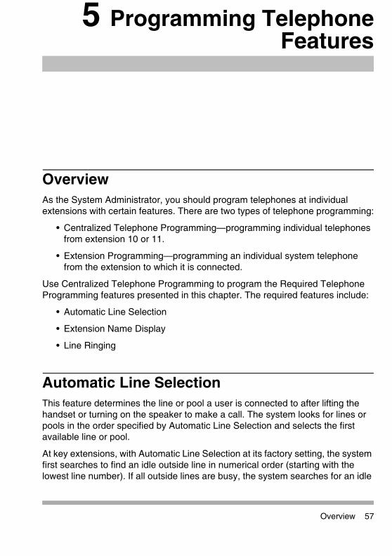
Overview 57
5 Programming TelephoneFeatures
OverviewAs the System Administrator, you should program telephones at individual extensions with certain features. There are two types of telephone programming:
• Centralized Telephone Programming—programming individual telephones from extension 10 or 11.
• Extension Programming—programming an individual system telephone from the extension to which it is connected.
Use Centralized Telephone Programming to program the Required Telephone Programming features presented in this chapter. The required features include:
• Automatic Line Selection
• Extension Name Display
• Line Ringing
Automatic Line SelectionThis feature determines the line or pool a user is connected to after lifting the handset or turning on the speaker to make a call. The system looks for lines or pools in the order specified by Automatic Line Selection and selects the first available line or pool.
At key extensions, with Automatic Line Selection at its factory setting, the system first searches to find an idle outside line in numerical order (starting with the lowest line number). If all outside lines are busy, the system searches for an idle

5 Programming Telephone Features
58 Automatic Line Selection
Quick Reference Guide
intercom line. This order can be changed, however, to accommodate your business needs. For example, a telemarketing firm with a WATS line (line 5) to reduce telephone expenses would set Automatic Line Selection for all telemarketers’ extensions to “05, 01, 02, 03, 04, Intercom.” This way the WATS line is selected first.
At pooled extensions, with Automatic Line Selection at its factory setting, the system first searches to find an available line in the main pool (pool 880 button 1, then button 2). If all outside lines in the pool are busy, the system selects an idle intercom line. However, you can change the order to accommodate a different automatic line selection. For example, your boss prefers her individual line (line 15) to be selected when she lifts the handset; then she wants auxiliary pool 881 to be selected, which is used for making international calls. To do this, set Automatic Line Selection to “15, 881, Intercom.”
If a single-line telephone user intends to place intercom calls and access system features, Automatic Line Selection for his or her extension should be set to intercom first for proper operation.
To program Automatic Line Selection for an extension:
1 Press f00ssc at extension 10 or 11.
2 Enter the number of the extension to be programmed for Automatic Line Selection.
3 Press **.
4 Press the line, pool, or i buttons in the desired order. The valid entries for Automatic Line Selection depend upon the type of extension:
• Key Extension: Outside system lines, Left Intercom (the factory setting)
• Pooled Extension: Pool 880 button 1, button 2, Left Intercom, Right Intercom (the factory setting), Pools 881-883, individual lines
5 To exit Automatic Line Selection, press **.
6 Press c and enter a new extension number, or exit programming mode.

5 Programming Telephone Features
Extension Name Display 59
Quick Reference Guide
Extension Name Display You can assign a name to an extension: up to 20 characters long on PARTNER telephones or up to 12 characters long on MLS telephones. When the extension is idle, the name and extension number appears on the system display telephone for that extension. When that extension is used to make an intercom, group, or transferred call, the name appears on the system display telephone receiving the call. Similarly, users receiving a transfer return call see the name of the person assigned to the extension that did not answer the transferred call. The following table shows the valid character entries for Extension Name Display.
Valid Character Entries
Letters Numbers
A = 21 N = 62 blank = 11
B = 22 O = 63 0 = 00
C = 23 P = 71 1 = 10
D = 31 Q = 72 2 = 20
E = 32 R = 73 3 = 30
F = 33 S = 74 4 = 40
G = 41 T = 81 5 = 50
H = 42 U = 82 6 = 60
I = 43 V = 83 7 = 70
J = 51 W = 91 8 = 80
K = 52 X = 92 9 = 90
L = 53 Y = 93
M = 61 Z = 94

5 Programming Telephone Features
60 Line Ringing
Quick Reference Guide
To assign a name to an extension:
1 Press f00ssc at extension 10 or 11.
2 Enter the number of the extension to be programmed.
3 Press left i.
4 Enter the two-digit code for each character you want to enter. For example, the name “Ed” is 3231.
5 If you make a mistake, press ! to clear the display. Repeat Step 4 to enter the correct name.
6 Program a button for this extension or exit programming mode.
Line Ringing This feature determines how each outside line or pool assigned to an extension rings. You can specify Immediate Ring, Delayed Ring (telephone rings after a 20-second delay), or No Ring.
Delayed Ring is useful for backup coverage on shared lines or pools, such as for secretaries who cover each other’s lines. No Ring is useful for all extensions except 10 when an operator answers all calls, or for telephones with no regular users, such as those in conference rooms.
To change the way outside lines or pools ring at an extension:
1 Press f00ssc at extension 10 or 11.
2 Enter the number of the extension to be programmed for Line Ringing.The green lights next to the line or pool buttons show the current Line Ringing settings for all lines or pools assigned to the extension. (If a line or pool is not assigned to a button, the green light next to that button is off.) The following ringing options can be shown by the green light next to the line or pool button:
• Immediate Ring — on steady
• Delayed Ring — flashes slowly

5 Programming Telephone Features
Line Ringing 61
Quick Reference Guide
• No Ring — flutters quickly
• Immediate Ring is the factory setting for lines; No Ring is the factory setting for pools.
3 Press the line or pool button until the button light shows the correct setting (the setting for the currently selected line or pool also appears on the display).
4 Continue programming, or exit programming mode.

5 Programming Telephone Features
62 Line Ringing
Quick Reference Guide

Overview 63
6 Maintaining Your System
OverviewOnce you have set up your system, you will need to maintain it. For example, changes in your business may require additional lines or extensions. And to prepare for emergencies such as power failures, you will want to back up all your customized feature settings so you can restore the system quickly.

6 Maintaining Your System
64 Backup and Restore
Quick Reference Guide
Backup and RestoreYou should back up the system programming periodically especially if you are changing the processor module or upgrading the system, or before and after any major programming changes. You can back up the programming to either the internal memory of the PARTNER ACS 509 processor module or a Backup/Restore PC Card. You can back up the programming automatically or manually. Occasionally you may have to restore programming from the backed-up file. The PARTNER system will automatically restore the most current backup file if it detects that the battery backup translation has been corrupted.
• If you make any changes to the system programming, PARTNER ACS R8.0 will automatically back up the system programming to the internal memory of the processor at 3 A.M. the next morning.
• If you have a PARTNER Remote Access PC Card, which allows you to program the system and perform backup and restore functions remotely or locally with a PC, you can also back up programming to this card. Backing up programming to a PC Card or a PC (via PARTNER ACS R8.0 PC Administration software) enables you to maintain a “removable” backup.
• Using a PC card does not back up the configuration of the 1600 DSL module. This configuration is retained in the flash memory of the 1600 DSL module, not on the PC card. When the system resets, the configuration in the flash memory of the 1600 DSL module becomes the active configuration for that module.

6 Maintaining Your System
Backup and Restore 65
Quick Reference Guide
Backup Programming—Automatic (#123)Use this feature to set up the automatic backup of all programming (except the system date, and time). When Backup Programming—Automatic is set to Active Internal or Active PC Card, the information is backed up at 2:00 a.m. on the next day to either the internal memory of the processor module or a Backup/Restore PC Card. From that point onward, the information is backed up at 2:00 a.m. on the first day of each month to either the internal memory of the processor module or a Backup/Restore PC Card. Active Internal scheduled backups and system initiated backups are stored in the same file.
If Backup Programming—Automatic is Active Internal or Active PC Card and an automatic backup fails, a Backup-Failure Alarm message appears (instead of the system date and time) on the top line of the telephone display at idle Extensions 10 and 11.
See Chapter 7, “If Something Doesn’t Work’ for an explanation of these messages and suggested corrective actions, and for the procedure for clearing the Backup-Failure Alarm message.
To change the setting for Backup Programming—Automatic:
1 If you want to back up to a PC Card, check that only one Backup/Restore PC Card is in the processor module.
2 Press f00ss#123 at extension 10 or 11.
3 To change the setting, press D or d until the setting you want appears, or press r to return the setting to the factory setting. The possible settings are:
• 1 = Active Internal
• 2 = Active PC Card
• 3 = Not Active (the factory setting)
• 4 = Backup Alarm Cleared
4 Exit programming mode.
For information about using Option 4, Backup Alarm Cleared, see “Clearing a Backup-Failure Alarm” on page 90.

6 Maintaining Your System
66 Backup and Restore
Quick Reference Guide
Backup Programming—Manual (#124)Use this feature to manually back up all the programming (except the system date and time) to either the internal memory of the processor module or a Backup/Restore PC Card.
To begin a manual backup of system settings:
1 If you want to back up to a PC Card, verify that only one Backup/Restore Card is in the processor module.
2 Press f00ss#124 at extension10 or 11.
The current setting appears.
3 To change the setting, press D or d until the setting you want appears, or press r to return to the factory setting. The possible settings are:
• 1 = Internal Memory
• 2 = PC Card
If there is a problem, a message appears (see Chapter 7, “If Something Doesn’t Work” for explanations and corrective actions).
If there is no problem, press e to begin the backup.
4 Press e.
A status message is displayed indicating that a backup is in progress, and within 30 seconds, a message appears indicating the result.
If the backup failed, an error message appears (see Chapter 7, “If Something Doesn’t Work,” for explanations and corrective actions).
• Backup Failed:Check Card
• Backup Failed:SystemBusy
• Backup Failed:Insert Valid Card
5 Exit programming mode.

6 Maintaining Your System
Backup and Restore 67
Quick Reference Guide
Restore Programming (#125) Use this feature to reinstate your system and telephone programming (except the System Day and System Time) to the settings saved on the processor module or a PC Card at the last system backup (manual or automatic). You should restore the system settings if your system settings become corrupted, if you make changes and decide you would rather use the former settings, or if you replace your processor module and want to retain the system settings you had on the previous processor module. A successful restore takes about five seconds.
To initiate a restore:
1 If you want to restore from a PC Card, verify that only one Backup/Restore Card is in the processor module. If you do not have a PC Card installed, see the PARTNER PC Card Installation Instructions that came with your PC Card.
2 Press f00ss#125 at extension 10 or 11.
3 Choose the backup file you want to use for the restore:
• 1 Internal Man.mmddyy, where “mmddyy” represents the date of the manual backup to the internal memory of the processor module
• 2 PC Card Man.mmddyy, where “mmddyy” represents the date of the manual backup on the PC Card
• 3 Internal AUTO.mmddyy, where “mmddyy” represents the date of the automatic backup to the internal memory of the processor module
• 4 PC Card AUTO.mmddyy, where “mmddyy” represents the date of the automatic backup on the PC Card
When a restore completes successfully, the Restore Complete message appears for two seconds at idle extensions 10 and 11. Then a System Reset—Programming Saved (#728) occurs, disconnecting any calls in progress. You should warn users before beginning a restore, or do the restore during nonbusiness hours.

6 Maintaining Your System
68 Backup and Restore
Quick Reference Guide
4 Press e to start the restore.
If the system detects an error before beginning the restore, the bottom line of the display shows one of the following messages:
• Insert Card or Insert Valid Card
• Bad File or Bad File-Try Again
• Incompat Version or Incompatible Versions
• Empty File
• System Busy
If the system does not detect an error, the restore begins. One of the following occurs:
• When the restore has completed successfully, the bottom line of the display shows Restore Complete for two seconds. All calls in progress are disconnected, and then the system resets itself. You are no longer in System Programming mode.
• If the restore is not successful, the display shows Restore Failed or Restore Failed-Try Again for two seconds. All calls in progress are disconnected and all of the system and telephone programming settings revert to the factory settings. You are no longer in System Programming mode. Try the restore again.
If the Backup/Restore PC Card is fresh from the factory, and no backups have been recorded on it yet, the filenames are PC CARD MAN.****** and PC CARD AUTO.******, respectively. (These file names are also used for the internal flash memory files.) You cannot use these files for a restore; they generate the error message Empty File after you press e in Step 4.
6 Maintaining Your System
Battery Replacement 69
Quick Reference Guide
Battery ReplacementThe processor module uses two user-replaceable AAA alkaline batteries. These batteries provide enough power to retain the system programming settings during a power failure for 45 days to six months, depending on the freshness of the batteries. When battery power is getting low, the system displays a ChgBat W/PowerOn or ReplaceSysBat W/Power On message on the top line of display telephones at extensions 10 and 11 in place of the default day/date/time message. You should replace the batteries within 45 days of seeing the message.
CAUTION:Do not turn off the power or remove the processor module before replacing the batteries! If you do, all settings for system and telephone programming revert to the factory settings. If you have a Backup/Restore PC Card, do a backup before changing the batteries.
Change the batteries in the processor module every year, even if the system has not yet displayed the ReplaceSysBat W/Power On message. Choose good quality alkaline batteries. (See “Inserting Batteries in the Processor Module” on page 19.)
The message may flicker on and off as the batteries approach the low-power threshold.

6 Maintaining Your System
70 Upgrade the System Software Using a PC Card
Quick Reference Guide
Upgrade the System Software Using a PC CardFollow these steps to upgrade your system’s software with a PC card:
CAUTION:Before starting, verify that you have batteries installed in the processor module by viewing the display of the telephone at extension 10.
1 If you have a 5-slot carrier, move the carrier’s On/Off switch to the “Off” position (“O”).
2 For all types of installations, disconnect the power cord from the wall outlet.
3 If you do not have a 5-slot carrier, go to Step 4.
If you have a 5-slot carrier:
a Loosen the thumb screw at the bottom of the carrier cover.
b Rotate the carrier cover to disengage the tabs at the top of the modules from the openings on the top of the carrier cover.
CAUTION:Remove all other PC Cards from the processor before initiating an upgrade.
4 To insert the PC Card, hold it with the label facing to the right, and slide it gently into either PC Card slot on the processor module. When inserted properly, the PC Card projects about 1-5/8 inch (4 cm) from the module.
You can also upgrade the system software for a PARTNER ACS R8.0 system via PARTNER ACS R8.0 PC Administration software. See the PARTNER ACS R8.0 PC Administration Getting Started for more information.

6 Maintaining Your System
Upgrade the System Software Using a PC Card 71
Quick Reference Guide
5 Power up the system:
a Reconnect the power cord.
CAUTION:The power cord should hang straight down from the connector, flush against the plastic case. Do not install the power cord at an angle to the case or with a loop in it.
b If you have a 5-slot carrier, move the carrier’s On/Off switch to the “On” position (“—”).
The LEDs on the processor module (center slot) will alternate red/green while the upgrade is being performed. When the upgrade is finished, the LED will appear steady green.
6 Make sure each module has a green LED in the same horizontal area, and that they all appear steady green. This indicates that each module is powered up.
• If a single light is out, power down the control unit, reseat the module and power up the control unit.
• If multiple lights are out, power down the control unit, reseat the leftmost module that has a light out, and power up the control unit.
• If the lights are still out, call for support as instructed on the inside front cover of this guide.
• PARTNER ACS Release 8.0 provides a firmware upgrade capability for the 1600 DSL module. If you are performing a firmware upgrade of this module, see “Upgrading 1600 DSL and 012E Module Firmware” on page 75 for a description of how the LEDs appear during the upgrade.
• PARTNER ACS Release 8.0 provides a firmware upgrade capability for the 012E module. If you are performing a firmware upgrade of this module, see “Upgrading 1600 DSL and 012E Module Firmware” on page 75 for a description of how the LEDs appear during the upgrade.

6 Maintaining Your System
72 Upgrade the System Software Using a PC Card
Quick Reference Guide
7 Do not remove the PC card. The card automatically converts to a backup/restore and remote access card. If you removed other PC cards, PVM or ASA/DXD, for example, power down the system and reinstall the PC cards after the upgrade is complete.
8 If you have a 2-slot carrier or a stand-alone configuration, you are finished with this procedure. If you have a 5-slot carrier, continue with Step 9.
9 Make sure all modules are seated properly.
10 Perform the following steps to replace the cover for the 5-slot carrier:
a Position the carrier cover over the modules so that the openings on the top of the carrier cover align correctly with the tabs at the top of the installed 5-slot carrier and modules.
b Rotate the carrier cover into position so that it aligns correctly with the thumb screw opening on the bottom of the carrier.
c Tighten the thumb screw. To ensure proper alignment and safe operation, tighten the thumb screw securely.

6 Maintaining Your System
Restore a PARTNER R6.0/7.0 Backup File to a PARTNER R8.0 System 73
Quick Reference Guide
Restore a PARTNER R6.0/7.0 Backup File to a PARTNER R8.0 SystemUse this procedure to restore a PARTNER R6.0 or R7.0 backup translation file to a PARTNER R8.0 system. The PARTNER R8.0 system will automatically convert the R6.0 or R7.0 translation file to an R8.0 translation working copy, enabling you to upgrade an existing PARTNER system more quickly and easily.
Considerations• After the restore operation is complete, the original R6.0/R7.0 backup file is
still present on the processor module or PCMCIA card.
• Since the PARTNER ACS 509 module has one more extension and two more lines than the PARTNER ACS 308 processor module, the extension cords for each extension will need to be moved to the preceding extension jack at the system location. For example, if the PARTNER R6.0 system had extensions beyond extension 17, you would need to move these extension cords down by one physical extension jack. Similarly, if the PARTNER R6.0 system had lines beyond line 3, you would need to move these lines down by two line extension jacks.
• If the PARTNER R6.0 system had a PARTNER Messaging expansion module (which does not contain physical extension jacks), you will need to increase the extension numbers in the Voice Mail Hunt Group by one and reprogram them manually.
• When restoring a PARTNER R6.0 backup translation file to a PARTNER R8.0 system, and the R6.0 system uses Simultaneous Paging or Loudspeaker Paging, you must manually move the loudspeaker paging cord to an available line jack and then manually program that line as the Loudspeaker Paging Line (#617).
• When restoring a PARTNER R6.0 backup translation file to a PARTNER R8.0 system, and the R6.0 system has automatic backup enabled, the R8.0 system keeps automatic backup enabled to the PC Card destination. Therefore, you must physically move the backup card from the R6.0 system to the R8.0 system processor so that the automatic backups continue to function.

6 Maintaining Your System
74 Restore a PARTNER R6.0/7.0 Backup File to a PARTNER R8.0 System
Quick Reference Guide
ProcedureTo restore a PARTNER R6.0/7.0 backup to a PARTNER R8.0 system:
1 Back up the existing PARTNER R6.0/R7.0 system to a PC Card. See “Backup Programming—Manual (#124)” on page 66.
2 Upgrade the PARTNER system to Release 8.0.
3 Restore the PARTNER R6.07/R7.0 back up from the PC Card to the PARTNER R8.0 system. See “Restore Programming (#125)” on page 67.
4 Back up the PARTNER ACS system. See “Backup Programming—Manual (#124)” on page 66.
At this point, you should modify the system programming (if necessary).
• If the PARTNER R6.0 system uses Simultaneous Paging or Loudspeaker Paging, you must manually move the loudspeaker paging cord to an available line jack and then manually program that line as the Loudspeaker Paging Line (#617).
• If the PARTNER R6.0 system has automatic backup enabled, the R8.0 system keeps automatic backup enabled to the PC Card destination. Therefore, you must physically move the backup card from the R6.0 system to the R8.0 system processor so that the automatic backups continue to function.

6 Maintaining Your System
Upgrading 1600 DSL and 012E Module Firmware 75
Quick Reference Guide
Upgrading 1600 DSL and 012E Module FirmwarePARTNER ACS Release 8.0 provides a firmware upgrade capability for the 1600 DSL module, which is equipped with programmable flash memory. The firmware to upgrade this module resides on a Backup/Restore PC Card.
PARTNER ACS Release 8.0 provides a firmware upgrade capability for the 012E module, which is equipped with programmable flash memory. The firmware to upgrade this module resides on a Backup/Restore PC Card.
The steps to perform a firmware upgrade are the same as those to upgrade the system software. See “Upgrade the System Software Using a PC Card” on page 70.
Check the LEDsWhile a 1600 DSL or 012E module is undergoing a firmware upgrade, the power LEDs appear as follows:
• The power LED on the 1600 DSL and/or the 012E module is initially steady green for 10 to 20 seconds, then flashes for another 5 to 10 seconds.
• The LED on the processor module flashes green while the firmware upgrade is in progress.
• The LEDs on other modules residing in the carrier that are not being upgraded are off.
The firmware upgrade process occurs for one module at a time. After successful completion of the upgrade for one module, the system resets and begins the firmware upgrade of the next module, if required. The firmware upgrades begin with modules in the left-most slot to the right-most slot of the carrier. Once a
Some modules do not display the LED off during a firmware upgrade of other modules. The power LED on the 1600 DSL module is steady green and the power LED on the PARTNER Messaging module is steady amber while firmware is upgraded on other modules.

6 Maintaining Your System
76 Upgrading T1 Module Firmware
Quick Reference Guide
successful firmware upgrade as been completed for all modules, all power LEDs are steady green.
Upgrading T1 Module FirmwarePARTNER ACS Release 8.0 provides a firmware upgrade capability for the T1 module, which is equipped with programmable flash memory. The firmware to upgrade this module can resides on a Backup/Restore PC Card.
The steps to perform a firmware upgrade are the same as those to upgrade the system software. See “Upgrade the System Software Using a PC Card” on page 70.
Once a successful firmware upgrade as been completed, all power LEDs are steady green.
The T1 module may take up to a minute to initialize.

6 Maintaining Your System
Adding New Modules 77
Quick Reference Guide
Adding New ModulesAdding new modules to an existing 5-slot carrier is very similar to installing the control unit.
CAUTION:Before starting, verify that you have batteries installed in the processor module by viewing the display of the telephone at extension 10.
Follow these steps to add a module to an existing 5-slot carrier:
1 Move the On/Off switch to the “Off” position (“O”).
2 Remove the power cord from the wall outlet.
3 Perform the following steps to remove the cover:
a Loosen the thumb screw at the bottom of the carrier cover.
b Rotate the carrier cover to disengage the tabs at the top of the modules from the openings on the top of the carrier cover.
4 Before installing a module, remove the clear, plastic protector from the connector area on the rear of the module by grasping the tabs on the ends of the protector and lifting.
Use these instructions if you are adding modules to an existing 5-slot carrier. If you are upgrading from a stand-alone PARTNER ACS processor module to a 2-slot carrier, see “Wall-Mounting a Stand-Alone Processor Module and a 2-Slot Carrier” on page 14 for instructions.

6 Maintaining Your System
78 Adding New Modules
Quick Reference Guide
5 Before you insert the new module, make sure that the T1 module (if used) or 1600 DSL module (if used) is in the leftmost slot and that all 400 (or 200) modules are installed to the right of all 012E, 308EC, or 206 modules. If you need to move a module to accommodate the new one, see “Replacing Modules” on page 79.
6 Push slowly but firmly in the center of the module until the module locks into place and is attached to the rear of the carrier. Do not force the module. If the module does not insert easily, remove it, clear any obstruction, and reinsert it.
7 Connect line and/or extension jack cords to the new module (see “Connecting Lines and Extensions” on page 23).
8 Reconnect the power cord to the wall outlet.
CAUTION:The power cord should hang straight down from the connector, flush against the plastic case. Do not install the power cord at an angle to the case or with a loop in it.
9 Move the On/Off switch to the “On” position (“—”).
10 Check that all green lights on the fronts of the modules are lit:
• If a single light is out, power down the control unit, reseat the module, and power up the control unit.
• If multiple lights are out, power down the control unit, reseat the leftmost module that has a light out, and power up the control unit.
• If the lights are still out, call for support as instructed on the inside front cover of this guide.
11 Make sure all modules are seated properly. (The cover will not fit if the modules are not seated properly.)
PARTNER ACS Release 7.0 or later supports Endeavor telephones when an Endeavor 362EC module is installed in the carrier. Install the Endeavor 362EC module(s) to the right of the T1 module (if installed) or the 1600 DSL module (if one is installed) and to the left of all 400 and 200 modules.

6 Maintaining Your System
Replacing Modules 79
Quick Reference Guide
12 Perform the following steps to replace the cover:
a Position the carrier cover over the modules so that the openings on the top of the carrier cover align correctly with the tabs at the top of the installed 5-slot carrier and modules.
b Rotate the carrier cover into position so that it aligns correctly with the thumb screw opening on the bottom of the carrier.
c Tighten the thumb screw. To ensure proper alignment and safe operation, tighten the thumb screw securely.
Replacing ModulesReplacing system modules is similar to how the modules were installed into the control unit. The procedure varies slightly between the stand-alone/2-slot carrier configuration and the 5-slot carrier configuration.
Replacing Modules in a Stand-Alone or 2-Slot Carrier Configuration
CAUTION:Before starting, verify that you have batteries installed in the processor module by viewing the display of the telephone at extension 10.
To replace a module or modules in a stand-alone or 2-slot carrier configuration:
1 Remove the power cord from the wall outlet.
2 Check the slack in the wires. If there is not enough slack to remove the module without pulling the line and extension cords free, label and disconnect the wires before continuing.
3 For a stand-alone configuration:
a Remove the screws at the top and bottom of the processor module, and remove the module from the wall.
b Mount the new module by following the steps in “Wall-Mounting a Stand-Alone Processor Module and a 2-Slot Carrier” on page 14; then go to Step 9.

6 Maintaining Your System
80 Replacing Modules
Quick Reference Guide
4 For a 2-slot carrier configuration, do the following:
a Remove the long screw at the bottom of the modules.
b Remove the screws that attach the carrier to the modules.
c Pull the carrier to the right to remove it.
d Slide the top module to the left to disengage its interlocking mounting tracks from the processor module.
If you are replacing the processor module, go to Step e. If you are replacing the top module, continue with Step g.
e Remove the screw at the top of the processor module, and remove the module from the wall.
f Mount the new PARTNER ACS processor module by following the instructions in “Wall-Mounting a Stand-Alone Processor Module and a 2-Slot Carrier” on page 14 and “Inserting Batteries in the Processor Module” on page 19.
g Mount or remount the top module by following the steps in “Wall-Mounting a Stand-Alone Processor Module and a 2-Slot Carrier” on page 14.
5 Connect the line and extension cords one at a time, making sure to place the correct cords into their corresponding jacks on the new module. (See “Connecting Lines and Extensions” on page 23.)
6 Reconnect the power cord.
CAUTION:The power cord should hang straight down from the connector, flush against the plastic case. Do not install the power cord at an angle to the case or with a loop in it.

6 Maintaining Your System
Replacing Modules 81
Quick Reference Guide
Replacing Modules in a 5-Slot CarrierReplacing a module in a 5-slot carrier involves many of the steps used in installing the modules.
CAUTION:Before starting, verify that you have batteries installed in the processor module by viewing the display of the telephone at extension 10.
Follow these steps to replace a module in a 5-slot carrier:
1 Move the On/Off switch to the “Off” position (“O”).
2 Remove the power cord from the wall outlet.
3 Perform the following steps to remove the cover:
a Loosen the thumb screw at the bottom of the carrier cover.
b Rotate the carrier cover to disengage the tabs at the top of the modules from the openings on the top of the carrier cover.
4 Before installing a module, remove the clear, plastic protector from the connector area on the rear of the module by grasping the tabs on the ends of the protector and lifting.
5 Check the slack in the wires. If there is not enough slack to remove the module without pulling the line and extension cords free, label and disconnect the wires.
6 Place one hand on top of the module. With the other hand, grip the plastic bracket on the bottom front of the module, and pull out the old module.

6 Maintaining Your System
82 Replacing Modules
Quick Reference Guide
7 If you are replacing a module with one of a different type, make sure that the T1 module (if used) or the 1600 DSL module (if used) is in the leftmost slot, that all 400 (or 200) modules are installed to the right of all 012E, 308EC, or 206 modules, and that the processor module remains in the center slot.
8 To insert the replacement, once the module is properly seated, firmly push the center of the module until the connectors on the module lock into place, and the module is attached to the rear of the carrier. For proper engagement of the connectors, the module must be inserted straight into the carrier. A slight click indicates the connectors are engaged.
CAUTION:Do not force the module. Use the carrier shelf as a reference and do not tilt, slant or rotate the module. If the module does not insert easily, remove it, clear any obstruction, and reinsert it.
9 Connect the line and extension cords one at a time, making sure to place the correct cords into their corresponding jacks on the new module.
• The T1 module is assigned 16 lines, even though it has only one line jack. If you have a T1 module in a 5-slot carrier, label the line jacks on the module after the T1 module to begin with “22.”
• The 1600 DSL module is assigned 16 lines, even though it has only one line jack. If you have a 1600 DSL module in a 5-slot carrier, label the line jacks on the module after the 1600 DSL module to begin with “22.”
• PARTNER ACS Release 8.0 supports Endeavor telephones when an Endeavor 362EC module is installed in the carrier. Install the Endeavor 362EC module(s) to the right of the T1 module (if installed) or the 1600 DSL module (if installed) and to the left of all 400 and 200 modules.

6 Maintaining Your System
Replacing Modules 83
Quick Reference Guide
10 Reconnect the power cord.
CAUTION:The power cord should hang straight down from the connector, flush against the plastic case. Do not install the power cord at an angle to the case or with a loop in it.
11 Move the carrier’s On/Off switch to the “On” position (“—”).
12 Check that all green lights on the fronts of the modules are lit:
• If a single light is out, power down the control unit, reseat the module, and power up the control unit.
• If multiple lights are out, power down the control unit, reseat the leftmost module that has a light out, and power up the control unit.
• If the lights are still out, call for support as instructed on the inside front cover of this guide.
13 Make sure all modules are seated properly. (The cover will not fit if the modules are not seated properly.)
14 Perform the following steps to replace the cover:
a Position the carrier cover over the modules so that the openings on the top of the carrier cover align correctly with the tabs at the top of the installed 5-slot carrier and modules.
b Rotate the carrier cover into position so that it aligns correctly with the thumb screw opening on the bottom of the carrier.
c Tighten the thumb screw. To ensure proper alignment and safe operation, tighten the thumb screw securely.

6 Maintaining Your System
84 Changing System Settings
Quick Reference Guide
Changing System SettingsIf you are upgrading PARTNER ACS Release 8.0 to a newer release by using the PC Card upgrade, all of your system programming settings are converted to work with the new release. However, you may want to consider some additional programming for the features.
CAUTION:Remove all other PC Cards from the processor before initiating an upgrade.
For more information on using the PC Card Software Upgrade, see “Upgrade the System Software Using a PC Card” on page 70.
Changing the System Clock You may need to change the system clock for daylight savings time, after a prolonged power failure, or after a system reset. Use System Date (#101) and System Time (#103) to set the current date, day, and time.

6 Maintaining Your System
Adding Lines, Pools, and Extensions 85
Quick Reference Guide
Adding Lines, Pools, and ExtensionsAs your business grows or changes, so do your needs for your PARTNER ACS. As you upgrade to newer releases, you must program for new features. As you expand, you can add lines, pools, and extensions to your system.
Adding New LinesHow you add new lines to the system depends upon the type of extension you are adding them to.
Key Extensions
You can add individual lines to pooled extensions or add new lines to key extensions (all extensions in Key mode; in Hybrid mode, extension 10 and any extensions set to Key by using Line Access Mode (#301) are key extensions.)
If you add a line to your system, you may need to adjust some line settings:
• Dial Mode (#201) if the new line is a rotary line
• Line Assignment (#301) to assign the line to specific extensions
• Line Ringing (Centralized Telephone Programming) to specify when the line starts ringing at each extension that has the line
• Line Access Restriction (#302) to limit an extension’s access to the line
If you replace a module with a different type, be sure you check the telephone and line connections and verify system and telephone programming. In many cases, you may need to rearrange the connections and/or change telephone or system programming.

6 Maintaining Your System
86 Adding Lines, Pools, and Extensions
Quick Reference Guide
• The system automatically assigns the new line as the last line in the Automatic Line Selection sequence. If you want to change the order, use Automatic Line Selection.
Pooled Extensions
You can add new lines to existing pools if your system is configured for Hybrid mode. To assign a new line to a pooled extension as an individual line, use the features in “Key Extensions” above.
If you add a line to your system for use in an existing pool, use Dial Mode (#201) if the new line is a rotary line and Pool Line Assignment (#207) to add the line to an existing pool.
Do not use Number of Lines (#104) if you add lines to the system after initial setup because it changes Line Assignment (#301), Line Access Restriction (#302), Automatic Line Selection, and Line Ringing for existing lines back to factory settings. To add a new line without affecting other settings, use Line Assignment (#301).
Do not use Number of Lines (#104) if you add lines to the system after initial setup because it changes Pool Line Assignment (#207), Pool Extension Assignment (#314), Pool Access Restriction (#315), Automatic Line Selection, and Line Ringing for existing pools back to factory settings. Additionally, it changes Line Assignment (#301), Line Access Restriction (#302), Automatic Line Selection, and Line Ringing for individual lines back to factory settings. To change pool assignments without affecting other settings, use Pool Line Assignment (#207) and Pool Extension Assignment (#314).

6 Maintaining Your System
Adding Lines, Pools, and Extensions 87
Quick Reference Guide
Adding New PoolsYou can create new pools if your system is operating in Hybrid mode. If you add outside lines for use in a new pool, you may need to use the following features:
• Dial Mode (#201) if the new lines are rotary lines
• Pool Line Assignment (#207) to assign lines to the new pool
• Pool Extension Assignment (#314) to assign the new pool to specific extensions
• Line Ringing to specify when the new pool starts ringing at each extension that has the pool
• Pool Access Restriction (#315) to limit an extension’s access to all the lines in the new pool
• Automatic Line Selection to add the new pool to the extension’s Automatic Line Selection sequence
Adding New Extensions If you add an extension to your system, you can probably use Copy Settings (#399) to copy the settings of an existing extension.
Swapping Extensions If a user changes location but wants to keep the same extension number, you can make the change easily by changing the connection at the control unit.
For example, if the users at extensions 29 and 32 switch offices, you can disconnect the modular plugs from those extension jacks in the control unit. Then reconnect the plug from 32 into extension jack 29 and the plug from 29 into extension jack 32. Now the users can take their respective telephones to their new locations, keep the same extension numbers, and retain the telephones’ programmed settings.
In some cases, some system parameters may also need to be changed, i.e., pool extension assignments, when swapping extensions.

6 Maintaining Your System
88 Adding Lines, Pools, and Extensions
Quick Reference Guide

Overview 89
7 If Something Doesn’t Work
OverviewThis chapter gives you some tips for fixing common problems fast.
Your Release NumberThe software version you have installed on your processor partly determines what your system can do. Before you call the Helpline, identify your software version or release:
From a system phone with an LED display, press f 5 9.
A display similar to the following appears for 15 seconds (your release number follows the R., the country code follows the C0).
PACS R8.0 12X

7 If Something Doesn’t Work
90 Clearing a Backup-Failure Alarm
Quick Reference Guide
Clearing a Backup-Failure AlarmIf you use Backup Programming—Automatic (#123) or system initiated backups, and the automatic backup fails, a Backup-Failure Alarm message appears (instead of the default day/date/time message) on the top line of the telephone display at idle extensions 10 and 11.
After correcting the problem that caused the failure, clear the Backup-Failure Alarm by following these steps:
1 Press f00ss#123.
2 Press 4 to choose Option 4, “Backup Alarm Cleared.”
3 Exit programming mode.
• You cannot use D or d in this procedure to choose Option 4.
• Using Option 4 to clear a Backup-Failure Alarm does not change the setting for Backup Programming—Automatic (#123). It remains either Active or Not Active.

7 If Something Doesn’t Work
012E Module Power Management 91
Quick Reference Guide
012E Module Power ManagementThe power supply used in the 012E module is adequate to power the 12 ETR ports under normal conditions. However, if too many large PARTNER telephones (such as the PARTNER-34D) are off-hook with speakerphone volume set to high levels, the power supply could be overloaded. Power management of the 012E module eliminates the power supply overload.
When a power threshold is exceeded, all telephones connected to the 012E module will appear as follows:
• LED display dims to a minimal level
• Speakerphone volume is decreased
To clear this condition, place one of the telephones connected to the 012E module on-hook. The LED display and speakerphone volume on all telephones return to normal. If this power management event occurs frequently, you should consider moving some telephones to available ports on other modules.
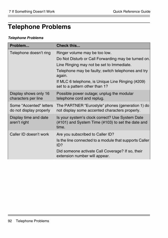
7 If Something Doesn’t Work
92 Telephone Problems
Quick Reference Guide
Telephone ProblemsTelephone Problems
Problem... Check this...
Telephone doesn’t ring Ringer volume may be too low.Do Not Disturb or Call Forwarding may be turned on.Line Ringing may not be set to Immediate.Telephone may be faulty; switch telephones and try again.If MLC 6 telephone, is Unique Line Ringing (#209) set to a pattern other than 1?
Display shows only 16 characters per line
Possible power outage; unplug the modular telephone cord and replug.
Some "Accented" letters do not display properly
The PARTNER "Eurostyle" phones (generation 1) do not display some accented characters properly.
Display time and date aren’t right
Is your system’s clock correct? Use System Date (#101) and System Time (#103) to set the date and time.
Caller ID doesn’t work Are you subscribed to Caller ID?Is the line connected to a module that supports Caller ID?Did someone activate Call Coverage? If so, their extension number will appear.
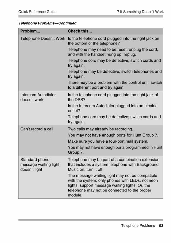
7 If Something Doesn’t Work
Telephone Problems 93
Quick Reference Guide
Telephone Doesn’t Work Is the telephone cord plugged into the right jack on the bottom of the telephone?Telephone may need to be reset; unplug the cord, and with the handset hung up, replug.Telephone cord may be defective; switch cords and try again.Telephone may be defective; switch telephones and try again. There may be a problem with the control unit; switch to a different port and try again.
Intercom Autodialer doesn’t work
Is the telephone cord plugged into the right jack of the DSS?Is the Intercom Autodialer plugged into an electric outlet?Telephone cord may be defective; switch cords and try again.
Can’t record a call Two calls may already be recording.You may not have enough ports for Hunt Group 7.Make sure you have a four-port mail system. You may not have enough ports programmed in Hunt Group 7.
Standard phone message waiting light doesn’t light
Telephone may be part of a combination extension that includes a system telephone with Background Music on; turn it off.The message waiting light may not be compatible with the system; only phones with LEDs, not neon lights, support message waiting lights. Or, the telephone may not be connected to the proper module.
Telephone Problems—Continued
Problem... Check this...

7 If Something Doesn’t Work
94 Calling Problems
Quick Reference Guide
Calling ProblemsCalling Problems
Problem... Check this...
Can’t make outside calls
Is Forced Account Code Entry assigned to this extension?Is your dial mode (touch-tone or rotary) incorrect? Use Dial Mode (#201) to reset it.Has someone changed the Outgoing Call Restriction for the extension?Did someone lock the extension with Station Lock? Use Station Unlock from extension 10 or 11 to unlock it.Local telephone company may not be receiving signals accurately. If problem is on just one telephone, see “Telephone Doesn’t Work” on page 93.Too many tip/ring devices may be trying to dial at once.Local telephone company line may be faulty; unplug each line from its module and test it by using a single-line telephone:
• If the trouble doesn’t occur on the single-line telephone, the problem is in your control unit.
• If the trouble occurs on the single-line telephone, switch the line cord and try again. If this doesn’t work, call the telephone company.
Can’t make outside calls from pool buttons on pooled extensions
Is Forced Account Code Entry assigned to this extension?Is your dial mode (touch-tone or rotary) incorrect? Use Dial Mode (#201) to reset it.Has someone changed the Pool Access Restriction for the extension?Pool may not be assigned to the extension.There may not be enough lines assigned to the pool to support the usage.One or more local telephone company lines may be faulty; test each line from extension 10.

7 If Something Doesn’t Work
Calling Problems 95
Quick Reference Guide
Calls are answered automatically
If Automatic System Answer and/or Direct Extension Dial is turned on, turn it off.If an auxiliary device (fax, modem, voice messaging system, answering machine) answers when it should not; either:
• Check the device and adjust it to answer on a later ring or turn off auto-answer.
• Set the extension’s Line Ringing to Delayed Ring.
Auxiliary device doesn’t answer
Device may not recognize the system ringing pattern:• Change the extension’s ring pattern by using
Distinctive Ring (#308).
• Change the setting for Intercom Dial Tone (#309) to Machine; the system will generate an outside dial tone for the extension.
Trouble hearing the person you called
If you are using a speakerphone, try using the handset.If you have touch-tone dialing, you may have a faulty telephone or cord.If you have rotary dialing, the Rotary Dialing Timeout (#108) interval is too long; reset it.
Automatically dialed calls beginning with star codes are misdialed
Setting may not be inserting a long enough pause; use Star Code Dial Delay (#410) to increase setting.
Recall feature isn’t working
Increase Recall Timer Duration (#107) by 100 milliseconds. If using the feature disconnects the call, decrease Recall Timer Duration by 100 milliseconds.
Calling Problems—Continued
Problem... Check this...

7 If Something Doesn’t Work
96 System Problems
Quick Reference Guide
System ProblemsSystem Problems
Problem... Check this...
Call rings continuously, but no one at other end
You may be using Automatic System Answer or Direct Extension Dial on a system that doesn’t support far end disconnect; call your local telephone company and find out if they support it.
Calls on hold are disconnected
Hold Disconnect Time (#203) setting may be too short.
Calls on Automatic System Answer lines are disconnected
Automatic System Answer Mode (#121) may be set to Disconnect; change it to Hold or Ring.
Call on Hold hangs up, but line doesn’t disconnect
Hold Disconnect Time (#203) may be too long; try resetting it.Local telephone company does not send a hold release signal; you may need the help of our hotline.
All calls are disconnected
You may have run the Restore Programming feature; the system resets itself. In the future, warn users of restores.Power may have been interrupted to the control unit; check the power cord, the on/off switch, and the green LEDs on the modules.
All telephones dead; no dial tone or lights
Power may have been interrupted to the control unit; check the power cord, the on/off switch, and the green LEDs on the modules.Power outlet may be faulty; test the outlet with an appliance like a lamp.
Multiple telephones dead; no dial tone or lights
LED on one system module may be out; try reseating the module in the control unit.LEDs on several modules may be out; try reseating the leftmost module of the ones with lights out.

7 If Something Doesn’t Work
T1 Module Problems 97
Quick Reference Guide
T1 Module ProblemsRefer to the PARTNER ACS R8.0 PC Administration online help.

7 If Something Doesn’t Work
98 1600 DSL Module Problems
Quick Reference Guide
1600 DSL Module Problems1600 DSL Module Problems
Problem... Check this...
The connection between the 1600 DSL module and the service provider’s gateway is not working.
The 1600 DSL module and the gateway used by the service provider are not communicating properly. Either something is faulty in the 1600 DSL module, or the configuration of the module does not match the configuration needed by the service provider’s gateway. Check the connection between the 1600 DSL module and the service provider’s gateway in the following order:
1 Check the status of the module by looking at the SDSL port LED or by looking at the Reports menu in the terminal emulation program.
2 Check the data link connection (Frame Relay or ATM).
3 Check the voice gateway connection.
4 Check the LAN connection.
For more detailed instructions, see the PARTNER Advanced Communications System Release 8.0 Installation, Programming, and Use guide.

7 If Something Doesn’t Work
Tip/Ring Device Problems 99
Quick Reference Guide
Tip/Ring Device ProblemsTip/Ring Device Problems
Problem... Check this...
Tip/ring device does not answer
Device does not recognize the distinctive ringing pattern used by the system. Set Distinctive Ring (#308) for that extension to Not Active.
Tip/ring device does not dial out properly
Device does not recognize the intercom dial tone generated by the system. Change the setting for Intercom Dial Tone (#309) for that extension to Machine.
Call records wrap on SMDR printout
SMDR Talk Time (#611) is set to Active and SMDR Output Format (#610) is set to 24 digits; the length of the fields is greater than the 80 characters supported by the printer.Reduce the font size, or increase the characters-per-inch setting for the printer.

7 If Something Doesn’t Work
100 Tip/Ring Device Problems
Quick Reference Guide

10
1
Sys
tem
Pro
gram
min
g Fl
ow C
hart
—H
ow to
Use
8 S
yste
m P
rogr
amm
ing
Flow
Cha
rts
To u
se th
e fo
llow
ing
sets
of F
low
Cha
rts,
follo
w th
ese
inst
ruct
ions
firs
t:
Plac
e th
e Pr
ogra
mm
ing
Ove
rlay
on th
e di
al p
ad o
f the
sys
tem
dis
play
pho
ne a
t ext
ensi
on
10 o
r 11.
•To
Sta
rt S
yste
m P
rogr
amm
ing:
—P
ress
f 0
0
—P
ress
s s
•
To E
nd S
yste
m P
rogr
amm
ing:
—P
ress
f 0
0
•To
Use
a S
peci
fic P
roce
dure
:
—D
ial #
and
a th
ree-
digi
t pro
cedu
re c
ode.
(Exa
mpl
e:#
1 0
1 fo
r Sys
tem
Dat
e)
•To
Cyc
le th
roug
h Sy
stem
Pro
gram
min
g Pr
oced
ures
:
—P
ress
N o
r P
•To
Cyc
le T
hrou
gh A
vaila
ble
Setti
ngs:
—P
ress
D o
r d
•
To R
etur
n to
Fac
tory
Set
ting:
—P
ress
r
Pro
cedu
res
# 20
7, #
313,
#31
4, a
nd #
315—
show
n in
squ
are
dotte
d bo
xes—
are
for p
ools
Pro
cedu
res
#399
, #60
9, a
nd #
728—
show
n in
das
hed
boxe
s—ar
e sk
ippe
d w
hen
cycl
ing
= Fa
ctor
y se
tting
= B
utto
n w
ith li
ghts
requ
ired
= Bu
tton
with
ligh
ts re
com
men
ded
Icon
Des
crip
tion

102Sys
tem
Flo
w C
hart
—S
yste
mSy
stem
Dat
e D
ial #
1 0
1D
ial t
he d
ate
(MM
DD
YY
)
Syst
em T
ime
Dia
l # 1
0 3
Dia
l the
tim
e (H
HM
M-2
4 hr
. milit
ary
time)
Num
ber o
f Lin
es
Dia
l # 1
0 4
Dia
l tw
o di
gits
(01–
31) (
R4
or la
ter)
or, D
ial t
wo
digi
ts (0
1–19
(Prio
r R4)
, fo
r # o
f out
side
line
s as
sign
ed to
ev
ery
exte
nsio
n. 3
per
AC
S
proc
esso
r & 3
08E
C m
odul
e. 1
6 fo
r T1
/DS
L m
odul
e. 2
per
206
or 2
00
mod
ule
. 4 p
er 4
00E
C m
odul
e .
WA
RN
ING
D
o no
t use
Num
ber o
f Lin
es (#
104)
afte
r in
itial
set
up. I
n K
ey m
ode,
the
Num
ber o
f lin
es p
roce
dure
will
cha
nge
Line
A
ssig
nmen
t (#3
01),
Line
Acc
ess
Res
trict
ion
(#30
2), A
utom
atic
Lin
e S
elec
tion
and
Line
Rin
ging
to fa
ctor
y se
tting
s.
To c
hang
e lin
e as
sign
men
ts w
ithou
t af
fect
ing
othe
r set
tings
, use
Lin
e A
ssig
nmen
t (#3
01).
In H
ybrid
mod
e, th
e N
umbe
r of L
ines
pr
oced
ure
will
cha
nge
Poo
l Lin
e A
ssig
nmen
t (#2
07),
Poo
l Ext
ensi
on
Ass
ignm
ent (
#314
), an
d P
ool A
cces
s R
estri
ctio
n (#
315)
. Add
ition
ally,
it
chan
ges
Line
Ass
ignm
ent (
#301
), Li
ne
Acc
ess
Res
trict
ion
(#30
2), A
utom
atic
Li
ne S
elec
tion
and
Line
Rin
ging
. To
chan
ge p
ool a
ssig
nmen
ts w
ithou
t af
fect
ing
othe
r set
tings
, use
Poo
l Lin
e A
ssig
nmen
t (#2
07) a
nd P
ool E
xten
sion
A
ssig
nmen
t (#3
14).
Tran
sfer
Ret
urn
Rin
gs
Dia
l # 1
0 5
Dia
l 1 d
igit
(0–9
) for
# o
f rin
gs b
efor
e ca
ll re
turn
s.
0–9
rings
4 rin
gs
0 rin
gs=n
o re
turn
Rec
all T
imer
Dur
atio
ns
Dia
l # 1
0 7
Dia
l tw
o di
gits
(01–
80) t
o se
t len
gth
of a
sw
itcho
ok fl
ash
=18
(450
m
sec)
Rot
ary
Dia
ling
Tim
eout
Dia
l # 1
0 8
Dia
l 1=4
sec
s2=
8 se
cs
3=12
sec
s
Out
side
Con
fere
nce
Den
ial
Dia
l # 1
0 9
Dia
l 1=A
llow
ed
2=D
isal
low
ed
Aut
omat
ic S
yste
m A
nsw
er D
elay
Dia
l # 1
1 0
Dia
l a ri
ng d
elay
num
ber (
0–9)
2 rin
gs
Dire
ct Ex
tens
ion
Dia
l Del
ay
Dia
l # 1
1 2
Dia
l a ri
ng d
elay
num
ber (
0–9)
2 rin
gs
, 0
rings
=ans
wer
ed im
med
iate
ly
Aut
omat
ic S
yste
m A
nsw
er
But
ton
Dia
l # 1
1 1
Dia
l 1=A
ssig
ned,
2=N
ot A
ssig
ned
3=
Sel
ect B
utto
n th
en p
ress
a
prog
ram
mab
le b
utto
n
Dire
ct E
xten
sion
Dia
l But
ton
Dia
l # 1
1 3
Dia
l 1=A
ssig
ned
2=N
ot A
ssig
ned
3=Se
lect
But
ton
then
pre
ss a
pr
ogra
mm
able
but
ton
Out
goin
g Cal
l R
estr
ictio
n B
utto
nD
ial #
1 1
4D
ial 1
=Ass
igne
d2=
Not
Ass
igne
d
3=S
elec
t But
ton
then
pre
ss a
pr
ogra
mm
able
but
ton
Wak
e U
p Se
rvic
e B
utto
n
Dia
l # 1
1 5
Dia
l 1=A
ssig
ned
2=N
ot A
ssig
ned
3=Se
lect
But
ton
then
pre
ss a
pr
ogra
mm
able
but
ton
Rin
g O
n Tr
ansf
er
Dia
l # 1
1 9
Dia
l 1=A
ctiv
e 2=
Not
Act
ive
Aut
omat
ic S
yste
m A
nsw
er M
ode
Dia
l # 1
2 1
Dia
l 1=H
old
2=D
isco
nnec
t3=
Rin
g
Cal
ler I
D T
ype
Dia
l # 1
2 2
Dia
l 1=U
SA
2=S
inga
pore
Bac
kup
Prog
ram
min
g A
utom
atic
Dia
l # 1
2 3
Dia
l 1=A
ctiv
e In
tern
al2=
Act
ove
PC
Car
d3=
Not
Act
ive
Bac
kup
Prog
ram
min
g—M
anua
lD
ial #
1 2
4D
ial 1
=Int
erna
l Mem
ory
2=P
C C
ard
Pre
ss e
to b
egin
the
back
up
Res
tore
Pro
gram
min
g
Dia
l # 1
2 5
Dia
l 1=I
nter
nal M
an.m
mdd
yy
2=P
C C
ard
Man
.mm
ddyy
3=In
tern
al A
UTO
.mm
ddyy
2=P
C C
ard
AU
TO.m
mdd
yyP
ress
e to
beg
in th
e re
stor
e
Aut
omat
ic D
aylig
ht/
Stan
dard
Tim
esD
ial #
1 2
6D
ial 1
=Act
ive

10
3
Sys
tem
Flo
w C
hart
—S
yste
m (C
ontin
ued)
Hol
d R
emin
der T
one
Dia
l # 1
2 7
Dia
l 0=N
ot A
ctiv
e1=
10 s
econ
ds2=
20 s
econ
ds3=
30 s
econ
ds4=
45 s
econ
ds5=
60 s
econ
ds
6=90
sec
onds
7=12
0 se
cond
s8=
150
seco
nds
9=18
0 se
cond
s
Mod
e of
Ope
ratio
n
Pres
s #
1 9
8En
ter t
he s
yste
m p
assw
ord
Dia
l 1=K
ey (f
acto
ry s
ettin
g)
2=H
ybrid
Syst
em R
eset
—Pr
ogra
mm
ing
Save
d
IMP
OR
TAN
T: U
sing
this
pro
cedu
re d
isco
nnec
ts a
ny a
ctiv
e ca
lls b
ut
reta
ins
syst
em s
ettin
gs. U
se it
onl
y if
the
syst
em fa
ils to
func
tion
corr
ectly
afte
r a p
ower
failu
re o
r dow
n pe
riod.
Dia
l # 7
2 8
.
Net
wor
k Ti
me
Sync
hron
izat
ion
Dia
l # 1
2 8
Dia
l 1=A
ctiv
e 2
=Not
Act
ive

104Sys
tem
Flo
w C
hart
—S
yste
m S
peed
Dia
l Num
bers
Sys
tem
Flo
w C
hart
—Li
nes
Dia
l Mod
e
Dia
l # 2
0 1
Dia
l a s
yste
m li
ne n
umbe
rD
ial 1
=Tou
ch-T
one
2=R
otar
yP
ress
n to
pro
gram
ano
ther
line
Hol
d D
isco
nnec
t Tim
e
Dia
l # 2
0 3
Dia
l a s
yste
m li
ne #
Dia
l 00=
No
Det
ectio
n,
01=5
0 m
sec,
02=
100
mse
c, 0
3=15
0 m
sec,
04
=200
mse
c, 0
5=25
0 m
sec,
06=
300
mse
c,
07=3
50 m
sec,
08=
400
mse
c, 0
9=45
0 m
sec
10=5
00 m
sec,
11=
550
mse
c, 1
2=60
0 m
sec.
P
ress
n to
pro
gram
ano
ther
line
Aut
omat
ic S
yste
m A
nsw
er L
ines
Dia
l # 2
0 4
Dia
l a s
yste
m li
ne #
Dia
l 1=A
ssig
ned
2=N
ot A
ssig
ned
P
ress
n to
pro
gram
ano
ther
line
Dire
ct E
xten
sion
Dia
l Lin
es
Dia
l # 2
0 5
Dia
l a s
yste
m li
ne #
Dia
l 1=A
ssig
ned
2=N
ot A
ssig
ned
P
ress
n to
pro
gram
ano
ther
line
Gro
up C
all D
istr
ibut
ion
Dia
l # 2
0 6
Dia
l a g
roup
num
ber (
1–6,
7 fo
r VM
S)
Dia
l a s
yste
m li
ne #
Dia
l 1=A
ssig
ned
2=N
ot A
ssig
ned
3=V
MS
Lin
e C
over
(o
nly
for H
unt G
roup
7)
Pres
s n
to p
rogr
am a
noth
er li
ne
Line
Cov
erag
e Ex
tens
ion
Dia
l # 2
0 8
Dia
l a s
yste
m li
ne #
, the
n a
syst
em
exte
nsio
n #,
no
line
owne
d by
an
exte
nsio
n
Pre
ss n
to p
rogr
am a
noth
er li
neP
ress
r to
una
ssig
n ow
ners
hip
Uni
que
Line
Rin
ging
Dia
l # 2
0 9
Dia
l a s
yste
m li
ne #
Dia
l 1 2–8
Pool
Lin
e A
ssig
nmen
t
Dia
l # 2
0 7
Dia
l a s
yste
m li
ne #
Dia
l 1=N
o P
ool
2=M
ain
Poo
l 880
3=
Poo
l 881
4=P
ool 8
825=
Poo
l 883
Pre
ss n
to p
rogr
am a
noth
er li
ne
To re
mov
e a
num
ber:
Pre
ss f
00
to e
nter
pro
gram
min
g m
ode
Pre
ss f
Dia
l the
Sys
tem
Spe
ed D
ial n
umbe
r’s c
ode
(600
-699
)P
ress
!To
rem
ove
anot
her n
umbe
r, re
peat
:P
ress
f 0
0 to
exi
t pro
gram
min
g m
ode
To p
rogr
am a
num
ber:
Pre
ss f
00
to e
nter
pro
gram
min
g m
ode
Pre
ss f
Dia
l a th
ree-
digi
t cod
e (6
00–6
99)
Dia
l the
tele
phon
e nu
mbe
r—up
to 2
8 di
gits
incl
udin
g sp
ecia
l cha
ract
ers.
To
“mar
k” it
(to
over
ride
rest
rictio
ns),
dial
* b
efor
e th
e te
leph
one
#.To
pro
gram
ano
ther
num
ber,
or to
cha
nge
a nu
mbe
r, re
peat
:P
ress
N P
, ent
er a
new
ext
ensi
on #
and
repe
at
abov
e st
eps
Pre
ss f
00
to e
xit p
rogr
amm
ing
mod
e

10
5
Sys
tem
Flo
w C
hart
—E
xten
sion
sLi
ne A
ssig
nmen
t
Dia
l # 3
0 1
Dia
l a s
yste
m e
xten
sion
#
To re
mov
e al
l exi
stin
g lin
e as
sign
men
ts,
pres
s r
bef
ore
sele
ctin
g a
line
Dia
l a li
ne n
umbe
rD
ial 1
=Ass
igne
d 2=
Not
Ass
igne
d 3=
Sel
ect B
utto
n th
en p
ress
a
prog
ram
mab
le b
utto
n (to
ass
ign
the
line
to
that
but
ton)
. If y
ou u
se o
ptio
n 3
afte
r a li
ne
has
been
ass
igne
d, th
e lin
e m
oves
from
the
old
butto
n to
the
new
but
ton
you
sele
ct.
Dia
l a li
ne n
umbe
rP
ress
n to
pro
gram
ano
ther
line
for t
his
exte
nsio
n To
pro
gram
ano
ther
ext
ensi
on:
Pre
ss N
P, e
nter
a
new
ext
ensi
on #
and
repe
at a
bove
ste
ps
Line
Acc
ess
Res
tric
tion
Dia
l # 3
0 2
Dia
l a s
yste
m e
xten
sion
#D
ial a
sys
tem
line
#D
ial 1
=No
Res
trict
ion
, 2=O
utgo
ing
Onl
y,
3=In
com
ing
Onl
y, 4
=No
Acc
ess
(line
app
ears
on
but
ton,
but
you
can
use
line
onl
y to
pic
k up
a
trans
ferr
ed o
r hel
d ca
ll)To
pro
gram
ano
ther
ext
ensi
on:
Pre
ss N
P, e
nter
a
new
ext
ensi
on n
umbe
r and
repe
at a
bove
ste
ps
Dis
play
Lan
guag
e
Dia
l # 3
0 3
Dia
l a s
yste
m e
xten
sion
#D
ial 1
=Eng
lish
2=Sp
anis
h3=
Fren
chP
ress
n to
pro
gram
ano
ther
ex
tens
ion
Aut
omat
ic E
xten
sion
Priv
acy
Dia
l # 3
0 4
Dia
l a s
yste
m e
xten
sion
#D
ial 1
=Ass
igne
d2=
Not
Ass
igne
d
Pre
ss n
to p
rogr
am a
noth
er
exte
nsio
n
Abb
revi
ated
Rin
ging
Dia
l # 3
0 5
Dia
l a s
yste
m e
xten
sion
#D
ial 1
=Act
ive
(1 ri
ng)
2=N
ot A
ctiv
e (r
epea
ted
ringi
ng)
Pre
ss n
to p
rogr
am a
noth
er
exte
nsio
n
Tran
sfer
Ret
urn
Exte
nsio
n
Dia
l # 3
0 6
Dia
l a s
yste
m e
xten
sion
#D
ial #
of e
xten
sion
(10–
57) t
o w
hich
cal
l sh
ould
retu
rn if
not
ans
wer
ed, E
xten
sion
tra
nsfe
rrin
g ca
ll P
ress
n to
pro
gram
ano
ther
ex
tens
ion
Inte
rcom
Dia
l Ton
e
Dia
l # 3
0 9
Dia
l a s
yste
m e
xten
sion
#D
ial 1
=Reg
ular
2=
Mac
hine
P
ress
n to
pro
gram
ano
ther
ext
ensi
on
Aut
omat
ic V
MS
Cov
er
Dia
l # 3
1 0
Dia
l a s
yste
m e
xten
sion
#D
ial 1
=Ass
igne
d2=
Not
Ass
igne
d
Pre
ss n
to p
rogr
am a
noth
er e
xten
sion
Dis
tinct
ive
Rin
ging
Dia
l # 3
0 8
Dia
l a s
yste
m e
xten
sion
#D
ial 1
=Act
ive
2=N
ot A
ctiv
e
Pre
ss n
to p
rogr
am a
noth
er e
xten
sion
Forc
ed A
ccou
nt C
ode
Entr
y
Dia
l # 3
0 7
Dia
l a s
yste
m e
xten
sion
#D
ial 1
=Ass
igne
d2=
Not
Ass
igne
d
Pre
ss n
to p
rogr
am a
noth
er
exte
nsio
n

106Sys
tem
Flo
w C
hart
—E
xten
sion
s (C
ontin
ued)
Pool
Ext
ensi
on A
ssig
nmen
t D
ial #
3 1
4D
ial a
sys
tem
ext
ensi
on #
to re
mov
e ex
istin
g po
ol a
ssig
nmen
ts, p
ress
r
befo
re s
elec
ting
a lin
eD
ial a
poo
l acc
ess
code
(880
, 881
, 882
, or 8
83)
Dia
l 1=A
ssig
ned
880
2=N
ot A
ssig
ned
881
,882
,883
3=Se
lect
But
ton
then
pre
ss a
pr
ogra
mm
able
but
ton
(aux
iliar
y po
ols
only
)P
ress
N P
to e
nter
a
new
ext
ensi
on #
& re
peat
abo
ve s
teps
Cal
l Wai
ting
Dia
l # 3
1 6
Dia
l a s
yste
m e
xten
sion
#D
ial 1
=Ass
igne
d2=
Not
Ass
igne
d
Cal
ler I
D L
og A
nsw
ered
Cal
ls
Dia
l # 3
1 7
Dia
l a s
yste
m e
xten
sion
#D
ial 1
=Act
ive
2=N
ot A
ctiv
e
Cal
ler I
D L
og L
ine
Ass
ocia
tion
Dia
l # 3
1 8
Dia
l a s
yste
m e
xten
sion
#D
ial a
sys
tem
line
#P
ress
n to
pro
gram
ano
ther
ex
tens
ion
To a
ssoc
iate
ano
ther
ext
ensi
on:
Pre
ss N
P, e
nter
a
new
ext
ensi
on #
and
repe
at a
bove
ste
ps
Cal
ler I
D L
og A
ll C
alls
Dia
l # 3
1 9
Dia
l a s
yste
m e
xten
sion
#
Cal
l Cov
erag
e R
ings
Dia
l # 3
2 0
Dia
l one
dig
it (1
–9) f
or th
e #
of ri
ngs
befo
re th
e ca
ll is
sen
t to
the
cove
ring
exte
nsio
n2
rings
VMS
Cov
er R
ings
Dia
l # 3
2 1
Dia
l one
dig
it (1
–9) f
or th
e #
of ri
ngs
befo
re th
e ca
ll is
sen
t to
the
voic
e m
essa
ging
3
rings
Cop
y Se
tting
s
Dia
l # 3
9 9
Dia
l a s
ourc
e ex
tens
ion
# D
ial t
arge
t ext
ensi
on #
s
Line
Acc
ess
Mod
e D
ial #
3 1
3D
ial a
sys
tem
ext
ensi
on #
Dia
l 1=P
oole
d a
ll ex
tens
ions
exc
ept 1
02=
Key
e
xten
sion
10
only
Pool
Acc
ess
Res
tric
tion
Dia
l # 3
1 5
Dia
l a s
yste
m e
xten
sion
#
Dia
l a p
ool n
umbe
r (88
0, 8
81, 8
82, o
r 883
)D
ial 1
=No
Res
trict
ion
2=
Out
goin
g O
nly
3=In
com
ing
Onl
y4=
No
Acc
ess
Pres
s n
to p
rogr
am a
noth
er p
ool
To p
rogr
am a
noth
er e
xten
sion
: Pr
ess N
P to
en
ter a
new
ext
ensi
on #
& re
peat
abo
ve
step
s
Rem
ote
Cal
l For
war
ding
Dia
l # 3
2 2
Dia
l a s
yste
m e
xten
sion
#D
ial 1
=Ass
igne
d2=
Not
Ass
igne
d
Exte
rnal
Hot
line
Dia
l # 3
1 1
Dia
l a s
yste
m e
xten
sion
#D
ial 1
=Ass
igne
d2=
Not
Ass
igne
d
Pre
ss n
to p
rogr
am a
noth
er e
xten
sion
Voic
e In
terr
upt O
n B
usy
Dia
l # 3
1 2
Dia
l a s
yste
m e
xten
sion
#D
ial 1
=Ass
igne
d2=
Not
Ass
igne
d
Pre
ss n
to p
rogr
am a
noth
er e
xten
sion
Ove
rrid
e Li
ne R
ingi
ngD
ial #
3 2
4D
ial a
sys
tem
ext
ensi
on #
Dia
l 1=A
ctiv
e 2
=Not
Act
ive
Pers
onal
ized
Sta
tion
Rin
ging
Dia
l # 3
2 3
Dia
l a s
yste
m e
xten
sion
#P
ress
D to
sel
ect t
he ri
ng p
atte
rn

10
7
Sys
tem
Flo
w C
hart
—D
ialin
g R
estr
ictio
ns a
nd P
erm
issi
ons
Out
goin
g C
all R
estr
ictio
n
Dia
l # 4
0 1
Dia
l a s
yste
m e
xten
sion
#D
ial 1
=No
Res
trict
ion
2=In
side
Onl
y (in
terc
om)
3=Lo
cal O
nly
(inte
rcom
and
loca
l) Pr
ess n
to p
rogr
am a
noth
er
exte
nsio
n
Toll
Cal
l Pre
fix
Dia
l # 4
0 2
Dia
l 1=0
/1 p
lus
Are
a C
ode
and
# 2=
Are
a C
ode
and
# on
ly
Syst
em P
assw
ord
Dia
l # 4
0 3
Dia
l fou
r dig
its to
set
the
pass
wor
d
Dis
allo
wed
Lis
t Ass
ignm
ents
Dia
l # 4
0 5
Dia
l a s
yste
m e
xten
sion
#D
ial a
list
# (1
–8)
Dia
l 1=A
ssig
ned
2=N
ot A
ssig
ned
P
ress
n to
pro
gram
ano
ther
list
To p
rogr
am a
noth
er e
xten
sion
: P
ress
N P
to e
nter
a
new
ext
ensi
on #
& re
peat
abo
ve s
teps
Emer
genc
y Ph
one
Num
ber L
ists
Dia
l # 4
0 6
Dia
l a li
st #
(01–
10)
To a
dd e
ntry
:D
ial t
he te
leph
one
# (u
p to
12
digi
ts)
Pre
ss e
Pre
ss r
to re
mov
e a
list e
ntry
Pre
ss n
to p
rogr
am a
noth
er li
st e
ntry
Allo
wed
Lis
t Ass
ignm
ents
Dia
l # 4
0 8
Dia
l a s
yste
m e
xten
sion
#D
ial a
list
# (1
–8)
Dia
l 1=A
ssig
ned
2=N
ot A
ssig
ned
P
ress
n to
pro
gram
ano
ther
list
To p
rogr
am a
noth
er e
xten
sion
: P
ress
N P
to
ente
r a n
ew e
xten
sion
# &
repe
at a
bove
ste
ps
Allo
wed
Pho
ne N
umbe
r Lis
ts
Dia
l # 4
0 7
Dia
l a li
st #
(1–8
)D
ial a
list
ent
ry (0
1–10
)To
add
ent
ry:
Dia
l the
tele
phon
e #
(up
to 1
2 di
gits
)P
ress
eP
ress
r to
rem
ove
a lis
t ent
ryP
ress
n to
pro
gram
ano
ther
list
ent
ryTo
pro
gram
ano
ther
list
: P
ress
N P
to e
nter
a
new
list
# &
repe
at a
bove
ste
ps
Dis
allo
wed
Pho
ne N
umbe
r Lis
ts
Dia
l # 4
0 4
Dia
l a li
st #
(1–8
)D
ial a
list
ent
ry (0
1–10
)To
add
ent
ry:
Dia
l the
tele
phon
e #
(up
to 1
2 di
gits
)Pr
ess e
Pres
s r
to re
mov
e a
list e
ntry
Pres
s n
to p
rogr
am a
noth
er li
st
entry
To p
rogr
am a
noth
er li
st:
Pres
s N
P to
en
ter a
new
list
# &
repe
at a
bove
ste
ps
Star
Cod
e D
ial D
elay
Dia
l # 4
1 0
Dia
l 0=0
Sec
onds
Del
ay
1=1
Sec
ond
Del
ay2=
2 S
econ
ds D
elay
3=3
Sec
onds
Del
ay4=
4 S
econ
ds D
elay
5=5
Sec
onds
Del
ay6=
Not
Act
ive
Forc
ed A
ccou
nt C
ode
List
Dia
l # 4
0 9
Dia
l a li
st #
(01–
99)
To a
dd e
ntry
:D
ial t
he a
ccou
nt c
ode
(up
to 6
dig
its)
Pre
ss e
Pre
ss r
to re
mov
e a
list e
ntry
Pre
ss n
to p
rogr
am a
noth
er li
st

108Sys
tem
Flo
w C
hart
—G
roup
s
Pick
up G
roup
Ext
ensi
on
Dia
l # 5
0 1
Dia
l a g
roup
# (1
–4)
Dia
l an
exte
nsio
n #
(10–
57)
Dia
l 1=A
ssig
ned
to g
roup
2=N
ot A
ssig
ned
to g
roup
Pre
ss n
to p
rogr
am a
noth
er e
xten
sion
Cal
ling
Gro
up E
xten
sion
s
Dia
l # 5
0 2
Dia
l a g
roup
# (1
–4)
Dia
l an
exte
nsio
n #
(10–
57)
Dia
l 1=A
ssig
ned
to g
roup
2=N
ot A
ssig
ned
to g
roup
Pre
ss n
to p
rogr
am a
noth
er
exte
nsio
n
Nig
ht S
ervi
ce B
utto
n
Dia
l # 5
0 3
Dia
l 1=A
ssig
ned
2=N
ot A
ssig
ned
3=
Sel
ect b
utto
n th
en p
ress
a
prog
ram
mab
le b
utto
n (to
ass
ign
Nig
ht
Ser
vice
to th
at b
utto
n)If
you
use
optio
n 3
afte
r a N
ight
Ser
vice
bu
tton
has
been
ass
igne
d, th
e N
ight
S
ervi
ce b
utto
n m
oves
from
the
old
butto
n to
the
new
but
ton
you
sele
ct
VMS
Hun
t Del
ay
Dia
l # 5
0 6
Dia
l 1=D
ay2=
Nig
htD
ial l
ine
num
ber
Dia
l 0–6 2
Nig
ht S
ervi
ce G
roup
Ext
ensi
ons
Dia
l # 5
0 4
Dia
l a s
yste
m e
xten
sion
#
Dia
l 1=A
ssig
ned
to g
roup
2=N
ot A
ssig
ned
to g
roup
Pre
ss n
to p
rogr
am a
noth
er e
xten
sion
Hun
t Gro
up E
xten
sion
s
Dia
l # 5
0 5
Dia
l a g
roup
# 1
–6, 7
for V
MS
, 8 fo
r fax
de
tect
ion
Dia
l a s
yste
m e
xten
sion
# (1
0–57
)D
ial 1
=Ass
igne
d to
gro
up2=
Not
Ass
igne
d to
gro
up
Pr
ess n
to p
rogr
am a
noth
er
exte
nsio
n
VMS
Hun
t Sch
edul
e
Dia
l # 5
0 7
Dia
l lin
e nu
mbe
rD
ial 1
=Alw
ays
2=D
ay O
nly
3=N
ight
Onl
y

10
9
Sys
tem
Flo
w C
hart
—A
uxili
ary
Equ
ipm
ent
Fax
Mac
hine
Ext
ensi
ons
Dia
l # 6
0 1
Dia
l a s
yste
m e
xten
sion
#
Dia
l 1=A
ssig
ned
2=N
ot A
ssig
ned
P
ress
n to
pro
gram
ano
ther
ex
tens
ion
Mus
ic-O
n-H
old
Dia
l # 6
0 2
Dia
l 1=A
ctiv
e 2=
Not
Act
ive
Hot
line
Dia
l # 6
0 3
Dia
l the
hot
line
exte
nsio
n #
(not
ext
. 10,
11,
or
the
first
two
exte
nsio
ns o
f any
206
or
308E
C m
odul
es)
Dia
l the
ale
rted
exte
nsio
n nu
mbe
r (no
t the
ho
tline
) or 7
0 to
pag
ing
syst
emTo
rem
ove
the
hotli
ne a
nd a
lert
:P
ress
r
Doo
rpho
ne 1
Ext
ensi
on
Dia
l # 6
0 4
Dia
l any
ext
ensi
on #
(exc
ept 1
0, 1
1, o
r the
fir
st tw
o ex
tens
ions
of a
ny 2
06 o
r 308
EC
m
odul
es)
To re
mov
e th
e do
orph
one
exte
nsio
n:P
ress
r
Doo
rpho
ne 2
Ext
ensi
on
Dia
l # 6
0 5
Dia
l any
ext
ensi
on (e
xcep
t 10,
11,
or t
he fi
rst
two
exte
nsio
ns o
f any
206
or 3
08E
C
mod
ules
)To
rem
ove
the
door
phon
e ex
tens
ion:
Pre
ss r
Doo
rpho
ne A
lert
Ext
ensi
on
Dia
l # 6
0 6
Dia
l any
ext
ensi
on #
(exc
ept a
doo
rpho
ne
exte
nsio
n)D
ial 1
=Not
an
aler
t 2=
Doo
rpho
ne 1
ale
rt3=
Doo
rpho
ne 2
ale
rt4=
Doo
rpho
nes
1 &
2P
ress
n to
iden
tify
anot
her e
xten
sion
(u
p to
48
aler
t ext
ensi
ons
per d
oorp
hone
)
Aut
omat
ed A
ttend
ant E
xten
sion
s
Dia
l # 6
0 7
Dia
l a s
yste
m e
xten
sion
#
Dia
l 1=A
ssig
ned
2=N
ot A
ssig
ned
P
ress
n to
pro
gram
ano
ther
ex
tens
ion.
SMD
R R
ecor
d Ty
pe
Dia
l # 6
0 8
Dia
l 1=A
ll ca
lls
2=O
utgo
ing
calls
onl
y
SMD
R T
op O
f Pag
e
Dia
l # 6
0 9
SMD
R O
utpu
t For
mat
Dia
l # 6
1 0
Dia
l 1=1
5 di
gits
2=
24 d
igits
Con
tact
Clo
sure
Gro
up
Dia
l # 6
1 2
Dia
l a g
roup
# (1
or 2
)D
ial a
n ex
tens
ion
# (1
0–57
)D
ial 1
=Ass
igne
d to
gro
up2=
Not
Ass
igne
d to
gro
up
Con
tact
Clo
sure
Ope
ratio
n Ty
pe
Dia
l # 6
1 3
Dia
l a C
onta
ct C
losu
re (1
or 2
)D
ial 1
=1-S
econ
d O
n2=
3-S
econ
ds O
n
3=5-
Sec
onds
On
4=To
ggle
SMD
R T
alk
Tim
e
Dia
l # 6
1 1
Dia
l 1=A
ctiv
e2=
Not
Act
ive

110Sys
tem
Flo
w C
hart
—A
uxili
ary
Equ
ipm
ent (
Con
tinue
d)
Rem
ote
Adm
inis
trat
ion
Pass
wor
d
Dia
l # 7
3 0
No
Pas
swor
d (8
das
hes
disp
lay)
Act
ive
pass
wor
d (u
p to
8 a
lpha
num
eric
cha
ract
ers)
Pas
swor
d ca
n on
ly b
e ch
ange
d at
Ext
ensi
on 1
0 or
11
Mus
ic-O
n-H
old
Volu
me
Dia
l # 6
1 4
Dia
l 1= 2= 3= 4= 5= 6= 7=
App
licat
ion
Prog
ram
min
g In
terf
ace
(API
)
Dia
l # 6
1 5
Dia
l 1=A
PI O
n2=
AP
I Off
App
licat
ion
Prog
ram
min
g In
terf
ace
(API
) Int
erna
l Mon
itor
Dia
l # 6
1 6
Dia
l 1=A
ll C
alls
2=E
xter
nal C
alls
Loud
spea
ker P
agin
g Li
ne
Dia
l # 6
1 7
Dia
l the
line
num
ber o
f the
jack
to w
hich
the
loud
spea
ker
pagi
ng s
yste
m is
con
nect
ed

111Cen
tral
ized
Tel
epho
ne P
rogr
amm
ing
Flow
Cha
rt—
How
to U
se
To u
se th
e C
entr
aliz
ed T
elep
hone
Pro
gram
min
g Fl
ow C
hart
, fol
low
thes
e in
stru
ctio
ns fi
rst:
Plac
e th
e Pr
ogra
mm
ing
Ove
rlay
on th
e di
alpa
d of
the
syst
em d
ispl
ay p
hone
at e
xten
sion
10
or 1
1.•
To E
nter
Pro
gram
min
g M
ode:
—P
ress
f 0
0
—P
ress
s s
c
—D
ial t
he e
xten
sion
num
ber t
o be
pro
gram
med
. But
tons
on
to w
hich
line
s or
poo
ls a
re a
ssig
ned
light
up
to s
how
the
curr
ent L
ine
Rin
ging
se
tting
: rem
aini
ng b
utto
ns c
an b
e pr
ogra
mm
ed w
ith A
uto
Dia
l num
ber o
r fe
atur
es•
To P
rogr
am A
noth
er F
eatu
re a
t the
Sam
e Ex
tens
ion:
—A
fter
you
prog
ram
one
feat
ure,
con
tinue
with
the
inst
ruct
ions
in th
e bo
x fo
r the
nex
t fea
ture
•To
Cha
nge
Setti
ng fo
r Ano
ther
Ext
ensi
on
—P
ress
c—
Dia
l the
new
ext
ensi
on’s
num
ber
•To
Era
se a
Fea
ture
or A
uto
Dia
l But
ton:
—P
ress
the
prog
ram
med
but
ton
—P
ress
!
•To
End
Pro
gram
min
g M
ode:
—P
ress
f 0
0
= Fa
ctor
y se
tting
= B
utto
n w
ith li
ghts
requ
ired
= B
utto
n w
ith li
ghts
reco
mm
ende
d
Icon
Des
crip
tion

11
2
Cen
tral
ized
Tel
epho
ne P
rogr
amm
ing
Flow
Cha
rt
Aut
omat
ic L
ine
Sele
ctio
n
Pre
ss *
*
Pre
ss th
e lin
e/po
ol/in
terc
om b
utto
ns in
the
desi
red
orde
rP
ress
* *
Key
Ext
ensi
on: O
utsi
de li
nes i
Pool
ed E
xten
sion
: Poo
l 880
but
ton
1,
butto
n 2,
i, r
ight
i
Poo
ls 8
81-8
83, i
ndiv
idua
l lin
es
Exte
nsio
n N
ame
Dis
play
Pre
ss i
E
nter
the
char
acte
r cod
es fo
r the
nam
e(S
ee ta
ble
“Val
id C
hara
cter
Ent
ries”
)
Line
Rin
ging
Pre
ss e
ach
line
or p
ool b
utto
n un
til th
e de
sire
d rin
ging
opt
ion
appe
ars
in th
e di
spla
y•
Imm
edia
te ri
ng (g
reen
ste
ady)
Lin
es
•N
o rin
g (g
reen
fast
flut
ter)
P
ools
•D
elay
ed ri
ng—
star
ts ri
ngin
g af
ter 2
0 se
cond
s (g
reen
slo
w fl
ashi
ng)
Bac
kgro
und
Mus
ic
Pre
ss a
pro
gram
mab
le b
utto
nP
ress
f 1
9
Pers
onal
Spe
ed D
ial N
umbe
rs
Pre
ss f
Dia
l a tw
o-di
git c
ode
(80–
99)
Dia
l the
pho
ne n
umbe
r—up
to 2
8 di
gits
in
clud
ing
spec
ial f
unct
ions
Aut
o D
ial N
umbe
rs—
Out
side
and
Insi
de
Pre
ss a
pro
gram
mab
le b
utto
nTo
pro
gram
an
outs
ide
num
ber:
Dia
l the
pho
ne n
umbe
r—up
to 2
8 di
gits
incl
udin
g sp
ecia
l fun
ctio
ns
To p
rogr
am a
n ex
tens
ion
num
ber:
Pre
ss i
D
ial t
he e
xten
sion
num
ber (
to ri
ng th
e ex
tens
ion)
or
* p
lus
the
exte
nsio
n nu
mbe
r (to
voi
ce-s
igna
l the
ex
tens
ion)
Cal
l For
war
ding
/Cal
l Fol
low
-Me
Pre
ss a
pro
gram
mab
le b
utto
nP
ress
f 1
1
Dia
l (op
tiona
l) tw
o-di
git o
rigin
atin
g ex
tens
ion
num
ber
Dia
l (op
tiona
l) tw
o-di
git d
estin
atio
n ex
tens
ion
num
ber
Cal
l Cov
erag
e
Pre
ss a
pro
gram
mab
le b
utto
nP
ress
f 2
0
Dia
l (op
tiona
l) tw
o-di
git o
rigin
atin
g ex
tens
ion
num
ber
Dia
l (op
tiona
l) tw
o-di
git d
estin
atio
n ex
tens
ion
num
ber
Cal
l Pic
kup
P
ress
a p
rogr
amm
able
but
ton
Pre
ss i
6
Dia
l the
two-
digi
t ext
ensi
on n
umbe
r
Cal
l Scr
eeni
ng
Pre
ss a
pro
gram
mab
le b
utto
n w
ithlig
hts
Pre
ss f
2 5
Cal
ler I
D In
spec
t P
ress
a p
rogr
amm
able
but
ton
with
light
sP
ress
f 1
7
NO
TE:
Pro
gram
Aut
omat
ic L
ine
Sele
ctio
n or
Ext
ensi
on N
ame
Dis
play
firs
t...th
en L
ine
Rin
ging
.
Cal
ler I
D C
all L
oggi
ng &
Dia
ling
Pre
ss a
pro
gram
mab
le b
utto
n w
ith li
ghts
Pre
ss f
2 3
Cal
ler I
D N
ame
Dis
play
P
ress
a p
rogr
amm
able
but
ton
with
lig
hts
Pre
ss f
1 6
Acc
ount
Cod
e En
try
Pre
ss a
pro
gram
mab
le b
utto
nP
ress
f 1
2
Cel
l Pho
ne C
onne
ct
P
ress
a p
rogr
amm
able
but
ton
Pre
ss f
1 1
D
ial t
wo-
digi
t orig
inat
ing
exte
nsio
n nu
mbe
rD
ial *
plu
s tw
o-di
git d
estin
atio
n P
erso
nal S
peed
Dia
l Num
ber
OR
THEN
Abs
ent T
ext M
essa
ge
Pre
ss a
pro
gram
mab
le b
utto
n w
ith li
ghts
Pre
ss f
2 8

113Cen
tral
ized
Tel
epho
ne P
rogr
amm
ing
Flow
Cha
rt—
Con
tinue
d
Do
Not
Dis
turb
P
ress
a p
rogr
amm
able
but
ton
with
ligh
tsP
ress
f 0
1
Dire
ct L
ine
Pick
up—
Idle
Lin
eP
ress
a p
rogr
amm
able
but
ton
with
ligh
tsP
ress
i 8
Con
tact
Clo
sure
1
Pre
ss f
Pre
ss a
pro
gram
mab
le b
utto
nP
ress
f 4
1
Con
tact
Clo
sure
2
Pre
ss a
pro
gram
mab
le b
utto
nP
ress
f 4
2
Dire
ct L
ine
Pick
up—
A
ctiv
e Li
neP
ress
a p
rogr
amm
able
but
ton
Pre
ss i
6 8
Last
Num
ber R
edia
l Pr
ess
a pr
ogra
mm
able
but
ton
Pres
s f
0 5
Excl
usiv
e H
old
Pre
ss a
pro
gram
mab
le b
utto
nP
ress
f 0
2
Gro
up C
allin
g—R
ing/
Page
For r
ingi
ng g
roup
: Pr
ess
a pr
ogra
mm
able
but
ton
Pres
s i
7
Dia
l a C
allin
g G
roup
num
ber (
1–4)
For p
agin
g gr
oup:
Pr
ess
a pr
ogra
mm
able
but
ton
Pres
s i
* 7
D
ial a
Cal
ling
Gro
up n
umbe
r (1–
4)
Gro
up H
untin
g—R
ing/
Voic
e Si
gnal
For r
ingi
ng th
e fir
st a
vaila
ble
exte
nsio
n:Pr
ess
a pr
ogra
mm
able
but
ton
Pres
s i
7 7
D
ial a
Hun
t Gro
up n
umbe
r (1–
7)Fo
r voi
ce s
igna
ling
the
first
ava
ilabl
e ex
tens
ion:
Pres
s a
prog
ram
mab
le b
utto
nPr
ess i
* 7
7
Dia
l a H
unt G
roup
num
ber (
1–6)
Gro
up P
icku
p Pr
ess
a pr
ogra
mm
able
but
ton
Pres
s i
6 6
D
ial a
Pic
kup
Gro
up n
umbe
r (1–
4)
Loud
spea
ker P
agin
g P
ress
a p
rogr
amm
able
but
ton
Pre
ss i
7 0
Man
ual S
igna
ling
Pre
ss a
pro
gram
mab
le b
utto
nP
ress
f 1
3D
ial a
two-
digi
t ext
ensi
on n
umbe
r (to
ring
ex
tens
ion)
or D
ial *
plu
s th
e tw
o-di
git
exte
nsio
n nu
mbe
r (to
voi
ce-s
igna
l the
ex
tens
ion)
Mes
sage
Lig
ht O
ff
Pre
ss a
pro
gram
mab
le b
utto
nP
ress
f 1
0
Dia
l (op
tiona
l) tw
o-di
git e
xten
sion
num
ber
Mes
sage
Lig
ht O
n
Pre
ss a
pro
gram
mab
le b
utto
nP
ress
f 0
9
Dia
l (op
tiona
l) tw
o-di
git e
xten
sion
num
ber
Rec
ord-
A-C
all
Pre
ss a
pro
gram
mab
le b
utto
n w
ith li
ghts
Pre
ss f
2 4
Con
fere
nce
Dro
p P
ress
a p
rogr
amm
able
but
ton
Pre
ss f
0 6
Hot
Dia
l
Pre
ss a
pro
gram
mab
le b
utto
n w
ith li
ghts
Pre
ss f
2 6
Mes
sage
Ale
rt N
otifi
catio
n
Pre
ss a
pro
gram
mab
le b
utto
n w
ith li
ghts
Pre
ss f
2 7
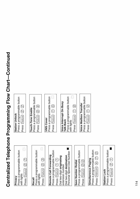
114Cen
tral
ized
Tel
epho
ne P
rogr
amm
ing
Flow
Cha
rt—
Con
tinue
d
Save
Num
ber R
edia
l
Pre
ss a
pro
gram
mab
le b
utto
n P
ress
f 0
4
Sim
ulta
neou
s Pa
ging
Pres
s a
prog
ram
mab
le b
utto
n Pr
ess i
* 7
0
Stat
ion
Lock
Pres
s a
prog
ram
mab
le b
utto
n Pr
ess f
2 1
Touc
h-To
ne E
nabl
e
Pre
ss a
pro
gram
mab
le b
utto
n P
ress
f 0
8
VMS
Cov
er
Pre
ss a
pro
gram
mab
le b
utto
n P
ress
f 1
5
Voic
e In
terr
upt O
n B
usy
Talk
-Bac
k P
ress
a p
rogr
amm
able
but
ton
with
ligh
tsP
ress
f 1
8
Stat
ion
Unl
ock
Pre
ss a
pro
gram
mab
le b
utto
n P
ress
f 2
2
Rem
ote
Cal
l For
war
ding
P
ress
a p
rogr
amm
able
but
ton
Pre
ss f
1 1
D
ial t
wo-
digi
t orig
inat
ing
exte
nsio
n nu
mbe
rD
ial t
wo-
digi
t des
tinat
ion
Per
sona
l Spe
ed D
ial N
umbe
r
Rec
all
Pre
ss a
pro
gram
mab
le b
utto
n w
ith li
ghts
Pre
ss f
0 3
Voic
e M
ailb
ox T
rans
fer
Pre
ss a
pro
gram
mab
le b
utto
n P
ress
f 1
4
Priv
acy
Pre
ss a
pro
gram
mab
le b
utto
n w
ith li
ghts
Pre
ss f
0 7

115Ext
ensi
on T
elep
hone
Pro
gram
min
g Fl
ow C
hart
—H
ow to
Use
To
use
the
Exte
nsio
n Te
leph
one
Prog
ram
min
g Fl
ow C
hart
, fol
low
thes
e in
stru
ctio
ns fi
rst:
To P
rogr
am a
t an
exte
nsio
n, u
se th
e fo
llow
ing
proc
edur
e:•
To S
tart
pro
gram
min
g:
—P
ress
f 0
0
—Th
e gr
een
light
nex
t to
butto
ns o
n w
hich
line
s or
poo
ls a
re a
ssig
ned
for
the
exte
nsio
n sh
ow th
e cu
rren
t Lin
e R
ingi
ng s
ettin
gs. Y
ou c
an
prog
ram
the
rem
aini
ng b
utto
ns w
ith te
leph
one
num
ber,
exte
nsio
n nu
mbe
rs, o
r sy
stem
feat
ures
.•
To a
ssig
n a
nam
e to
the
exte
nsio
n, p
ress
i, a
nd th
en e
nter
the
char
acte
r cod
es.
•To
Era
se th
e cu
rren
t pro
gram
min
g fr
om a
but
ton,
pre
ss th
e bu
tton,
then
pre
ss !
:
—P
ress
the
prog
ram
med
but
ton
—P
ress
!
•To
End
Pro
gram
min
g M
ode:
—P
ress
f 0
0
= Fa
ctor
y se
tting
= B
utto
n w
ith li
ghts
requ
ired
= B
utto
n w
ith li
ghts
reco
mm
ende
d
Icon
Des
crip
tion

116Ext
ensi
on T
elep
hone
Pro
gram
min
g Fl
ow C
hart
Exte
nsio
n N
ame
Dis
play
Pre
ss i
E
nter
the
char
acte
r cod
es fo
r the
nam
e(S
ee ta
ble
“Val
id C
hara
cter
Ent
ries”
)
Bac
kgro
und
Mus
ic
Pre
ss a
pro
gram
mab
le b
utto
nP
ress
f 1
9
Pers
onal
Spe
ed D
ial N
umbe
rs
Pre
ss f
Dia
l a tw
o-di
git c
ode
(80–
99)
Dia
l the
pho
ne n
umbe
r—up
to 2
8 di
gits
incl
udin
g sp
ecia
l fun
ctio
ns
Aut
o D
ial N
umbe
rs—
Out
side
and
Insi
de
Pre
ss f
0 0
P
ress
a p
rogr
amm
able
but
ton
To p
rogr
am a
n ou
tsid
e nu
mbe
r:D
ial t
he p
hone
num
ber—
up to
28
digi
ts in
clud
ing
spec
ial f
unct
ions
To
pro
gram
an
exte
nsio
n nu
mbe
r:P
ress
i
Dia
l the
ext
ensi
on n
umbe
r (to
ring
the
exte
nsio
n)
or *
plu
s th
e ex
tens
ion
num
ber (
to v
oice
-sig
nal
the
exte
nsio
n)
Cal
l For
war
ding
/Cal
l Fol
low
-Me
Pre
ss a
pro
gram
mab
le b
utto
n w
ith li
ghts
Pre
ss f
1 1
D
ial (
optio
nal)
two-
digi
t orig
inat
ing
exte
nsio
n nu
mbe
rD
ial (
optio
nal)
two-
digi
t des
tinat
ion
exte
nsio
n nu
mbe
r
Cal
l Cov
erag
e
Pre
ss a
pro
gram
mab
le b
utto
nP
ress
f 2
0
Dia
l (op
tiona
l) tw
o-di
git o
rigin
atin
g ex
tens
ion
num
ber
Dia
l (op
tiona
l) tw
o-di
git d
estin
atio
n ex
tens
ion
num
ber
Cal
l Pic
kup
Pre
ss a
pro
gram
mab
le b
utto
nP
ress
i 6
D
ial t
he tw
o-di
git e
xten
sion
num
ber
Cal
ler I
D In
spec
t P
ress
a p
rogr
amm
able
but
ton
with
lig
hts
Pre
ss f
1 7
Cal
ler I
D C
all L
oggi
ng &
Dia
ling
Pre
ss a
pro
gram
mab
le b
utto
n w
ith li
ghts
Pre
ss f
2 3
Con
fere
nce
Dro
p P
ress
a p
rogr
amm
able
but
ton
Pre
ss f
0 6
Cal
ler I
D N
ame
Dis
play
P
ress
a p
rogr
amm
able
but
ton
with
lig
hts
Pre
ss f
1 6
Acc
ount
Cod
e En
try
Pre
ss a
pro
gram
mab
le b
utto
nP
ress
f 1
2
Cel
l Pho
ne C
onne
ct
P
ress
a p
rogr
amm
able
but
ton
Pre
ss f
1 1
D
ial t
wo-
digi
t orig
inat
ing
exte
nsio
n nu
mbe
rD
ial *
plu
s tw
o-di
git d
estin
atio
n P
erso
nal S
peed
Dia
l Num
ber
Abs
ent T
ext M
essa
ge
Pre
ss a
pro
gram
mab
le b
utto
n w
ith li
ghts
Pre
ss f
2 8

11
7
Ext
ensi
on T
elep
hone
Pro
gram
min
g Fl
ow C
hart
—C
ontin
ued
Do
Not
Dis
turb
Pre
ss a
pro
gram
mab
le b
utto
n w
ith li
ghts
Pre
ss f
0 1
Dire
ct L
ine
Pick
up—
Idle
Lin
eP
ress
a p
rogr
amm
able
but
ton
with
ligh
tsP
ress
i 8
Con
tact
Clo
sure
1
Pre
ss f
Pre
ss a
pro
gram
mab
le b
utto
nP
ress
f 4
1
Con
tact
Clo
sure
2
Pre
ss a
pro
gram
mab
le b
utto
nP
ress
f 4
2
Dire
ct L
ine
Pick
up—
A
ctiv
e Li
neP
ress
a p
rogr
amm
able
but
ton
Pre
ss i
6 8
Last
Num
ber R
edia
l
Pre
ss a
pro
gram
mab
le b
utto
nP
ress
f 0
5
Excl
usiv
e H
old
Pre
ss a
pro
gram
mab
le b
utto
nP
ress
f 0
2
Gro
up C
allin
g—R
ing/
Page
For r
ingi
ng g
roup
: P
ress
a p
rogr
amm
able
but
ton
Pre
ss i
7
Dia
l a C
allin
g G
roup
num
ber (
1–4)
For p
agin
g gr
oup:
P
ress
a p
rogr
amm
able
but
ton
Pre
ss i
* 7
D
ial a
Cal
ling
Gro
up n
umbe
r (1–
4)
Gro
up H
untin
g—R
ing/
Voic
e Si
gnal
For r
ingi
ng th
e fir
st a
vaila
ble
exte
nsio
n:
Pre
ss a
pro
gram
mab
le b
utto
nP
ress
i 7
7
Dia
l a H
unt G
roup
num
ber (
1–7)
For p
agin
g th
e fir
st a
vaila
ble
exte
nsio
n:P
ress
a p
rogr
amm
able
but
ton
Pre
ss i
* 7
7
Dia
l a H
unt G
roup
num
ber (
1–6)
Gro
up P
icku
p
Pre
ss a
pro
gram
mab
le b
utto
nP
ress
i 6
6
Dia
l a P
icku
p G
roup
num
ber (
1–4)
Loud
spea
ker P
agin
g
Pre
ss a
pro
gram
mab
le b
utto
nP
ress
i 7
0
Man
ual S
igna
ling
Pres
s a
prog
ram
mab
le b
utto
nPr
ess f
1 3
Dia
l a tw
o-di
git e
xten
sion
nu
mbe
r (to
ring
ext
ensi
on) o
r D
ial *
plu
s th
e tw
o-di
git
exte
nsio
n nu
mbe
r (to
vo
ice-
sign
al th
e ex
tens
ion)
Mes
sage
Lig
ht O
ff
Pre
ss a
pro
gram
mab
le b
utto
nP
ress
f 1
0
Dia
l (op
tiona
l) tw
o-di
git e
xten
sion
nu
mbe
r M
essa
ge L
ight
On
Pres
s a
prog
ram
mab
le b
utto
nPr
ess f
0 9
D
ial (
optio
nal)
two-
digi
t ext
ensi
on
num
ber
Priv
acy
Pres
s a
prog
ram
mab
le b
utto
n w
ith li
ghts
Pres
s f
0 7
Rec
all
Pre
ss a
pro
gram
mab
le b
utto
n w
ith li
ghts
Pre
ss f
0 3
Rec
ord-
A-C
all
Pre
ss a
pro
gram
mab
le
butto
n w
ith li
ghts
Pre
ss f
2 4
Save
Num
ber R
edia
l
Pres
s a
prog
ram
mab
le b
utto
n Pr
ess f
04
Sim
ulta
neou
s Pa
ging
Pre
ss a
pro
gram
mab
le b
utto
n P
ress
i *
7 0
Stat
ion
Lock
Pre
ss a
pro
gram
mab
le b
utto
n P
ress
f 2
1
Stat
ion
Unl
ock
Pre
ss a
pro
gram
mab
le b
utto
n P
ress
f 2
2
Rem
ote
Cal
l For
war
ding
Pr
ess
a pr
ogra
mm
able
but
ton
Pres
s f
1 1
D
ial t
wo-
digi
t orig
inat
ing
exte
nsio
n nu
mbe
rD
ial t
wo-
digi
t des
tinat
ion
Pers
onal
Spe
ed D
ial N
umbe
r
Mes
sage
Ale
rt N
otifi
catio
n
Pre
ss a
pro
gram
mab
le b
utto
n w
ith li
ghts
Pre
ss f
2 7
Hot
Dia
l
Pre
ss a
pro
gram
mab
le b
utto
n w
ith li
ghts
Pre
ss f
2 6

118Ext
ensi
on T
elep
hone
Pro
gram
min
g Fl
ow C
hart
—C
ontin
ued
Touc
h-To
ne E
nabl
e
Pres
s a
prog
ram
mab
le b
utto
n Pr
ess f
0 8
VMS
Cov
er
Pres
s a
prog
ram
mab
le b
utto
n Pr
ess f
1 5
Voic
e In
terr
upt O
n B
usy
Talk
-Bac
k Pr
ess
a pr
ogra
mm
able
but
ton
Pres
s f
1 8
Voic
e M
ailb
ox T
rans
fer
Pres
s a
prog
ram
mab
le b
utto
n Pr
ess f
1 4