Part—II Requirements
79
Part—II Requirements
Transcript of Part—II Requirements
Part—II
Requirements
Section VI
Employer’s Requirements
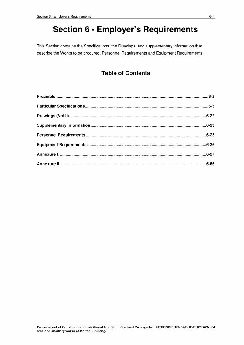
6-1 Section 6 - Employer’s Requirements
Section 6 - Employer’s Requirements
This Section contains the Specifications, the Drawings, and supplementary information that
describe the Works to be procured, Personnel Requirements and Equipment Requirements.
Table of Contents
Preamble.......................................................................................................................................6-2
Particular Specifications.............................................................................................................6-5
Drawings (Vol II).........................................................................................................................6-22
Supplementary Information......................................................................................................6-23
Personnel Requirements ..........................................................................................................6-25
Equipment Requirements .........................................................................................................6-26
Annexure I: .................................................................................................................................6-27
Annexure II: ................................................................................................................................6-66
Procurement of Construction of additional landfill Contract Package No : NERCCDIP/TR- 02/SHG/PH2/ SWM /04 area and ancillary works at Marten, Shillong.
6-2 Section 6 - Employer’s Requirements
Preamble
Shillong, located in the East Khasi Hills district, is the capital of Meghalaya, popularly referred as
“The Scotland of the East”. Shillong functioned, during the British regime, as the administrative
capital of the erstwhile Assam province apart from being the only major t ourist destination in the
0 0 0 0región. Situated at 25 31’ 26” -- 25 39’ 56” N Latitude and 91 47’ 20” -- 92 0’ 39” E Longitude,
the altitude of the city varies between 1400 and 1800 M above mean sea level (MSL). The
National Highway NH40 links Shillong with Guwahati and rest of the country. There is a minor
airport at Umroi, 35 KM from Shillong. Guwahati, the largest urban centre of the región, located
100KM from Shillong, is the nearest railhead and National airport.
It is one of the few Hill stations with motorable roads all around the city. Shillong has its own
charm, different from other Hill stations and presents a natural scenic beauty with wáterfalls,
brooks, pine groves and gadens. The place, the people, the flora and fauna and the climate all
combine to make Shillong an ideal resort throughout the year.
The Shillong city is located in seismic zone V. The slopes within the city are not very steep and
ranges from 5% to 10%. Shillong experiences a humid subtropical climate and is characterized by
moderate warm wet summers and cool dry winters. The growth trend in the city indicate a
physical growth of the city towards the north-eastern direction, where the new Shillong township
is proposed.
The existing Landfill site at Municipal Trenching Ground at Marten, Mawiong which has been
operational and used for disposal purposes since 1938. The site already includes an operating
compost facility.
The collected wastes throughout the city are disposed at Mawiong Disposal Site at a distance of
about 8KM from the city. The proposed Landfill Area is about 8500 Sq.m. There are no sensitive
receptors occuring within 500M of the site. Umiam Lake is approximately 3KM from the proposed
disposal site. The existing and the proposed Solid Waste Disposal Site and the existing Compost
Plant of 100 MTPD capacity is a part of Riatkhwan Reserve Forest.
Scope of Work
1. Construction of Retaining Wall for Landfill
• The height of RCC wall is 12.5 meters RCC Counterfort Retaining Wall – Length
of Retaining Wall is 254 meters,
• Stone Masonry Wall (Length=58.1m)
2. Landfill Life –
• Landfill area is about 8500 sq.m. (0.85 Ha.) only.
• Design Life of Landfill : 10 years from the date of commissioning
3. Landfill Design – Standard design of landfill as per MSW Rules 2000 is provisioned:
Procurement of Construction of additional landfill Contract Package No : NERCCDIP/TR- 02/SHG/PH2/ SWM /04 area and ancillary works at Marten, Shillong.
6-3 Section 6 - Employer’s Requirements
• 90 cm thick of clay liner constructed using wet clay or soil amended with
10% bentonite, having coefficient of permeability not greater than 1 x 10
7cm/sec, compacted clay or amended soil (Bentonite amended soil),
• 1.5mm thick HDPE geo-membrane liner
• 30 cm thick Drainage layer of silty sand material
• 30 cm thick Drainage layer of coarse sand material
• Since the RCC wall is a vertical structure Geo-synthetic Clay Liner (GCL) of
equivalent permeability requirement and HDPE sheet was proposed for the
sides of landfill.
4. Leachate Collection & Removal System:
• Leachate generated from the Landfill shall be collected and discharged
outside by the Leachate collection and removal system (HDPE perforated
pipes of 160 mm of feeder pipe and 315mm dia header pipe).
• 30 cm thick Drainage layer of silty sand material and 30 cm thick Drainage
layer of coarse sand material
• Leachate collection & treatment system to collect leachate from landfill area
5. Construction of Leachate Holding Tank -2 Nos
• Leachate holding tank size - 15.5 m x 5.5 m
• 30 Cu.m per day of leachate shall be treated by conventional leachate
treatment plant
6. Weigh Bridge, Boundary Wall with Barbed wire fencing, Main Gate & Cattle Trap
• Civil works for construction of Weigh bridge and installation of mechanical
equipments for Weigh Bridge
• Construction of 1000 m length Boundary wall RCC columns , 2.5 m panel,
( 1.7 m high), Barbed wire fencing,
• Main Gate for the facility with cattle trap
7. Construction of Storm Water Drain
• Open Concrete Drain 250 x 250 (Length=460m)
• Open Concrete Drain 900 x 900 (Length=500m)
8. Approach Road
• Construction of internal roads 5 m wide, 250 m length, 3.75 m black top,
9. Construction of Guard cum Weigh Bridge operator building,
10. Construction of Tube Well, Box culverts etc.
Procurement of Construction of additional landfill Contract Package No : NERCCDIP/TR- 02/SHG/PH2/ SWM /04 area and ancillary works at Marten, Shillong.
6-4 Section 6 - Employer’s Requirements
Specification Document (Vol III)
Issued separately as Volume III
Procurement of Construction of additional landfill Contract Package No : NERCCDIP/TR- 02/SHG/PH2/ SWM /04 area and ancillary works at Marten, Shillong.
6-5 Section 6 - Employer’s Requirements
Particular Specifications
• The works would be quoted for all lead and lift unless otherwise specified particularly in
the document.
• The Employer does not undertake to construct or make available any approach road to
the proposed worksite if not mentioned in the Bill of Quantities and the bidder shall get acquainted
with available means of approaches to the proposed site and quote for various items. The
Employer shall not be liable for any claim raised later on the plea of non availability or non access
to the site.
• The Contractor is advised to visit the site and acquaint himself of the prevailing local
conditions at site, labour, water and other material requirements etc; required for the successful
completion of the works
1.1. General
All the materials incorporated in the works shall be the most suitable for the duty concerned and
shall be new and of first class commercial quality, free from imperfections and selected for long
life and minimum maintenance. It shall be tested according to relevant IS Specifications in
qualified labs and certificates produced to the satisfaction of the Project Manager.
If the specification for a particular item is not given, relevant IS Specifications ,the Standard
Specifications of Meghalaya PWD or MSPHED or CPWD shall be followed.
The objective of the specifications given in this section is to specify the details pertaining to the
design, drawing, and selection of equipment or product. The equipment or product supplied shall
be of high standard of quality and best engineering practices and shall comply with all currently
applicable standards, regulations and codes.
Except as otherwise specified in this technical specification, the Indian/International Standards
and Codes of Practice in their latest version shall be adhered to for the design, manufacturing,
inspection, calibration, installation, field testing, packing, handling and transportation of product.
Should any product be offered conforming to other standards, the equipment or products shall be
equal to or superior to those specified and the documentary confirmation shall be submitted for
the prior approval of the Employer. In case of any discrepancy in interpretation of the code/ clause
the decision of the Project Manager shall be final and binding on the Contractor.
The successful contractor shall construct a Landfill facility at Marten as per the MSW Rules 2000
and requirements furnished below.
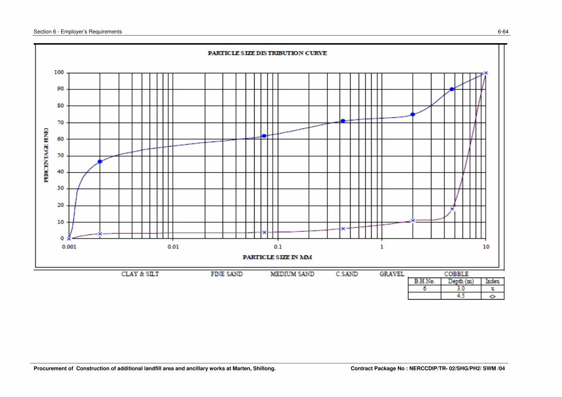
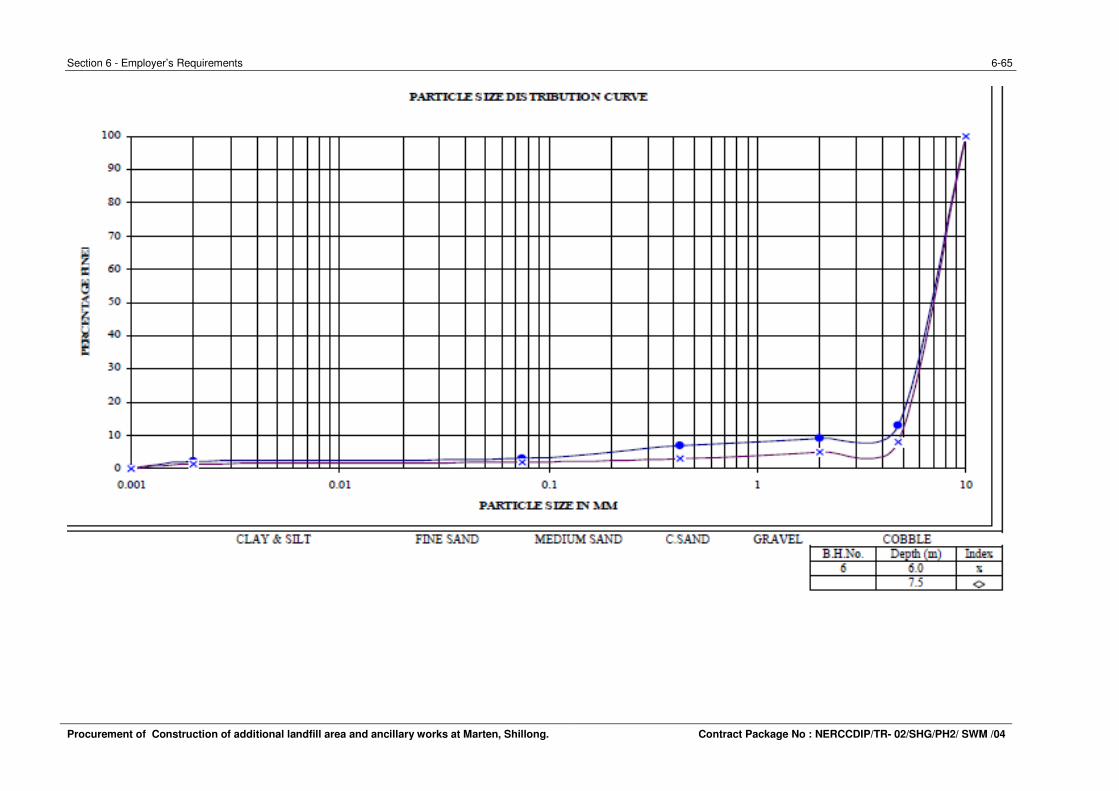
1.2. Topographical Survey & Geotechnical investigations
The indicative layout plan for proposed works is enclosed along with Tender Drawings for
reference. The Contractor shall provide the Total station along with the surveyor for total project
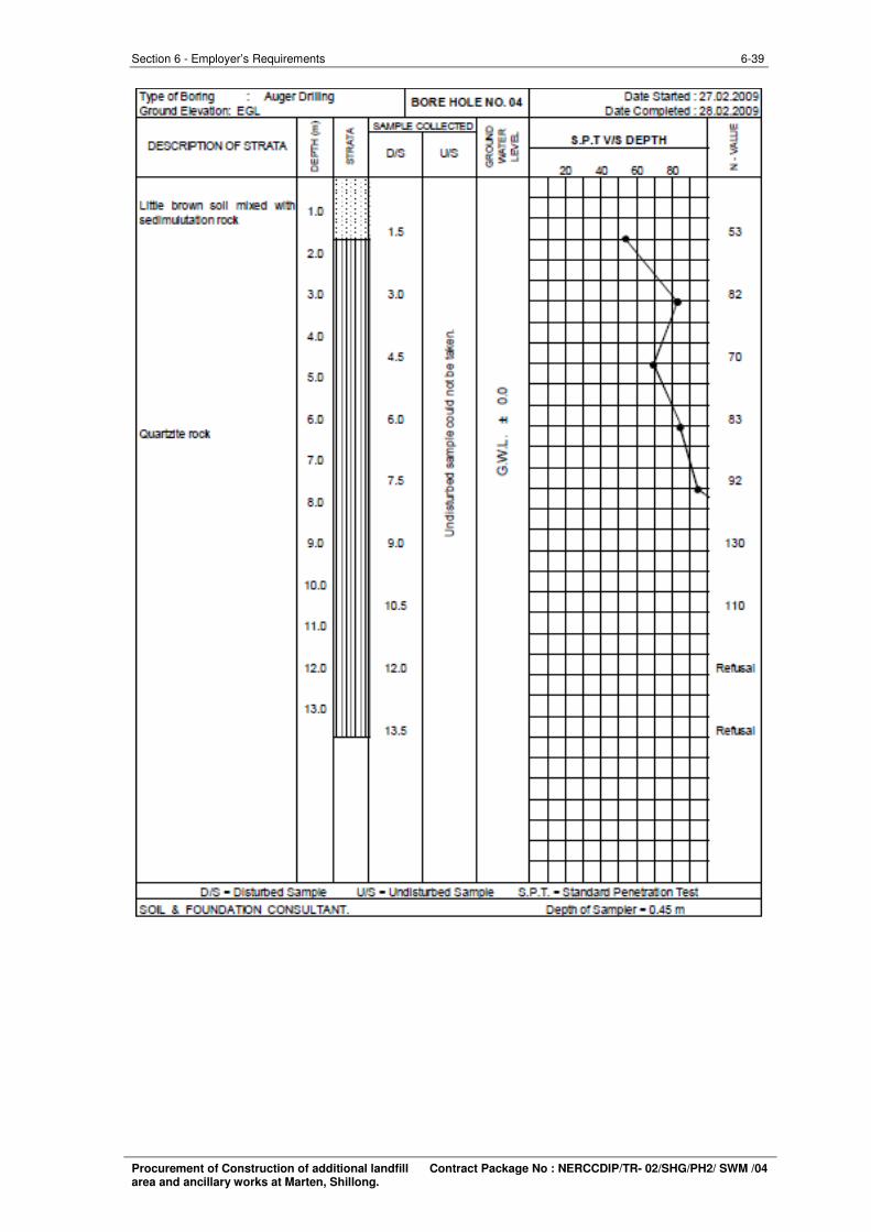
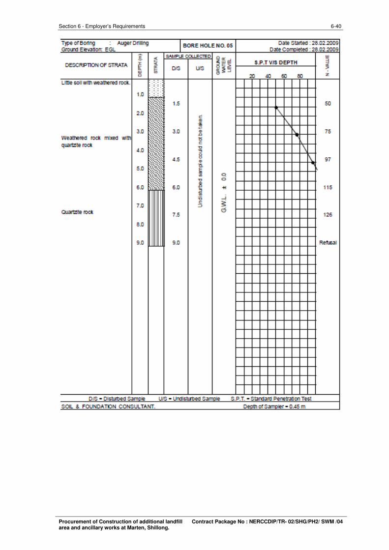
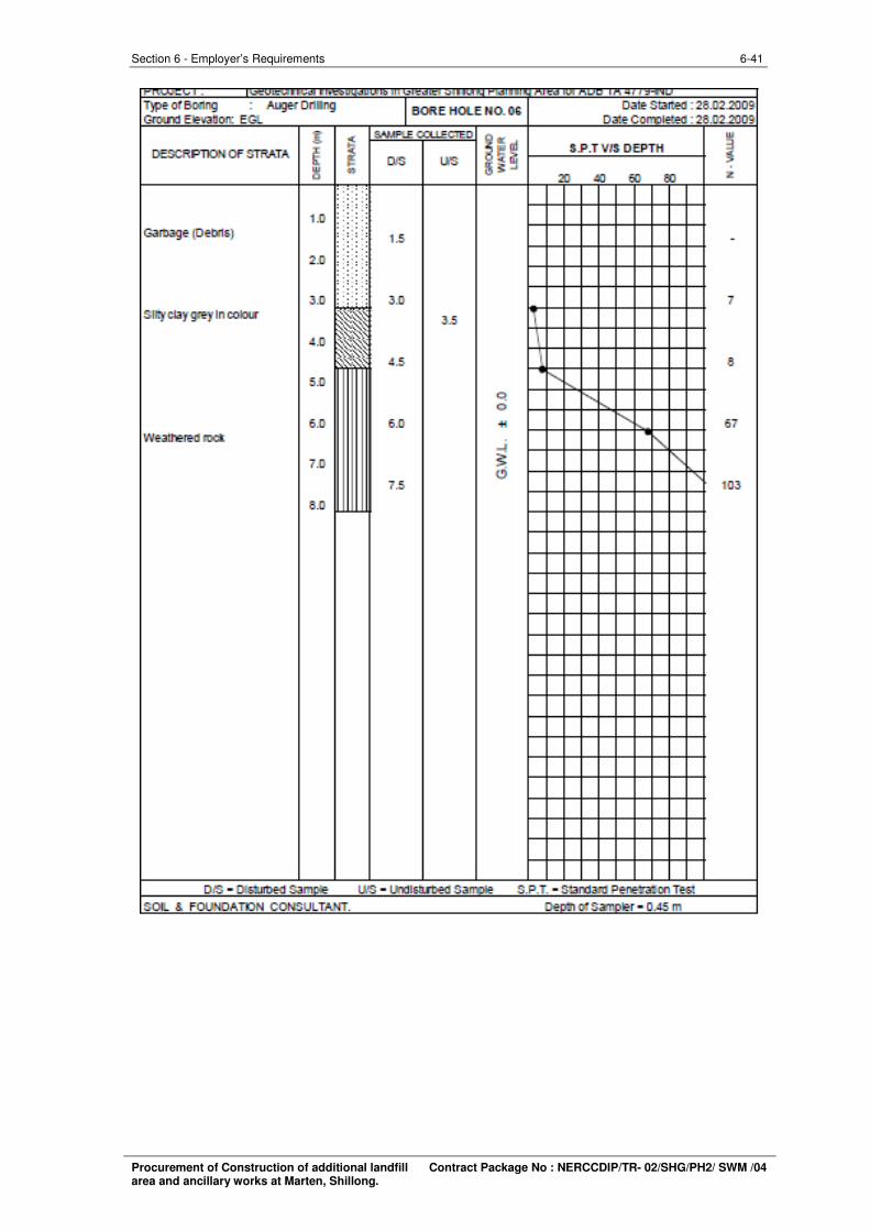
period. The report on geotechnical investigations are also appended herewith for reference. The
Contractor shall carryout the confirmatory topographical survey and geotechnical investigations of
his own and get satisfied before proceeding with the works. No extra cost shall be allowed by the
Employer for such survey and investigations to the Contractor. The Contractor shall submit two
hard and soft copies of the details of confirmatory topographical and Geotechnical surveys
conducted for approval of client.
Procurement of Construction of additional landfill Contract Package No : NERCCDIP/TR- 02/SHG/PH2/ SWM /04 area and ancillary works at Marten, Shillong.
6-6 Section 6 - Employer’s Requirements
1.3. Site grading
Before taking up the site grading works the Contractor shall fix the base grid and lines along with
bench mark stones and proceed with the grading works without disturbing the grid markings and
bench marks fixed for the purpose. The Contractor shall clear the site of all the shrubs and muck
if any before starting the excavation.
The excavation shall be done using hydraulic excavators & tippers with disposal upto 5 km for site
grading. For road work grading, hydraulic excavator of required power and capacity shall be used
along with tippers and earth shall be conveyed to the place shown by the Project Manager and
disposed as per the direction of the direction of Project Manager. The bidder shall ascertain the
soil quantity and nature of work for grading required through site visit before quoting for the
tender. The Contractor shall submit the excavation plan and shall carry out accordingly duly as
per the approved drawing and maintain the required slopes of the bund. The bunds shall be
trimmed manually to the required grade as shown in the drawings. The required site grading
vehicles and equipments shall be organized by the successful bidder before starting of the works.
1.4. RCC Counterfort Retaining wall
The construction of 12.50 m high RCC Counterfort type Retaining wall, shall be constructed on
the southern side of the landfill site. The total length of the wall is considered as 254 m
(Annexure -1 – Geo-technical Investigation Report attached). This wall shall be constructed on a
priority basis prior to the construction of landfill liner system. Considering a massive concrete
RCC works to be completed within the schedule period considering rainy days, therefore
successful bidder shall use following
(a) Mobile Batching Plant: Successful Bidder shall set up two mobile batching plant of
capacity 6 to 10 cum/hr. along with the concrete pumps.
(b) Shuttering Materials: A minimum of 3000 sq.m of sturdy steel shuttering along with
safety dismountable pipe scaffolding arrangements shall be arranged at the site.
(c) Concrete Vibrators: 10 sets of pneumatic needle vibrators to be provided,
(d) Laboratory : About 40 sets of Concrete testing cubes with UTM for testing shall be
provided at site. Other Laboratory equipments viz., Slump cone etc. shall be provided.
(e) The Contractor shall make his own arrangements for protection of Concrete due to rains
with required Tarpulin/PV sheets covers and also water pumping machinery required
arrangements for proper curing of concrete.
1.5. Landfill Construction
The Sanitary Landfill shall have protective measures against pollution of ground water and
surface water, emission of dust, wind blown, litter, bad odour, fire hazard, bird menace, pest or
rodents, green house gases, slope instability, erosion etc. The sanitary landfill site consists of
Procurement of Construction of additional landfill Contract Package No : NERCCDIP/TR- 02/SHG/PH2/ SWM /04 area and ancillary works at Marten, Shillong.
6-7 Section 6 - Employer’s Requirements
waste filling area and infrastructure support facilities. The support infrastructure (i.e., the
access road, equipment shelters, weighing bridge, temporary waste storage space, demarcation
of landfill areas for stockpiling cover materials and liner material, drainage facilities, leachate
collection, and treatment facilities etc) will be located in the layout. Since there is an availability of
adequate cover material at the site and the water table is far below, trench landfill is more
suitable. Grading required for landfill development will produce excavate which will be safely
stockpiled and used as cover material for the landfill operations. In order to avoid surface and
groundwater contamination, the excavated site is lined with low permeability (having permeability
coefficient not greater than 1 x 10⁻⁷ cm/sec) natural clay or amended soil (bentonite 10%) of
about 900 mm thick and 1.5 mm thick HDPE geo-membranes. Leachate collection lateral pipes
should be provided above the membranes in 300 mm thick silty sand layer and 300 mm coarse
sand layer. The 160mm collection (feeder) pipes should be provided at a spacing of 15m c/c.
Perforations should be laid at a slope of 1 in 100. Header pipes (315 mm dia) should be provided
connecting up to the leachate treatment plant. The detailed specifications and construction
methodology and tests etc are detailed below;
1.6. Specifications for Compacted Clays & Amended Soil for Landfill Liners
A competent barrier made of compacted soils – clays or amended soils – is normally expected to
fulfill the following requirements:
a) hydraulic conductivity of 10-7
cm/sec or less;
b) absence of shrinkage cracks due to desiccation;
c) absence of clods in the compacted clay layer;
d) adequate strength for stability of liner under compressive loads as well as along side
slopes; and
e) Minimal influence of leachate on hydraulic conductivity.
Clays of high plasticity with very low values of permeability (usually well below the prescribed
limit), exhibit extensive shrinkage on drying, as well as tend to form large clods during compaction
in the relatively dry state. Their permeability can also increase on ingress of certain organic
leachates. Well compacted inorganic clays of medium plasticity, either natural or amended,
appear to be most suitable for liner construction.
According to various investigations, soils with the following specifications would prove to be
suitable for liner constructions: Percentage fines – between 40 and 50%; plasticity index –
between 10 and 30%; liquid limit – between 25 and 30%; clay content – between 18 and 25%. It
is necessary to perform detailed laboratory tests and some field trial tests prior to liner
construction to establish that the requirements pertaining to permeability, strength, leachate
compatibility and shrinkage are met.
Procurement of Construction of additional landfill Contract Package No : NERCCDIP/TR- 02/SHG/PH2/ SWM /04 area and ancillary works at Marten, Shillong.
6-8 Section 6 - Employer’s Requirements
1. Design Process
The design process for a compacted soil liner consists of the following steps:
I. Identification of borrow area or source of material – in-situ or nearby.
II. For in-situ soils, conducting field permeability tests to assess suitability of the natural soil
in its in-situ condition.
III. Laboratory studies on liner material (from in-situ or nearby locations), comprising of soil
classification tests, compaction tests, permeability tests, strength tests, shrinkage tests,
compaction tests, permeability tests.
IV. Identification of source of additive, if natural soil does not satisfy liner requirements –
natural clay from not too distant areas or commercially available clay such as bentonite
(Annexure – 2 – Soil Bentonite Laboratory Test Report attached).
V. Laboratory studies (as detailed in (iii) above) on soil – additive mixes using different
proportions of additive to find minimum additive content necessary to achieve the
specified requirements.
VI. Field trial on test pads, to finalise compaction parameters (layer thickness, number of
passes, speed of compactor), as well as to verify that field permeability of the compacted
soil lies within pre-specified limits.
Procurement of Construction of additional landfill Contract Package No : NERCCDIP/TR- 02/SHG/PH2/ SWM /04 area and ancillary works at Marten, Shillong.
6-9 Section 6 - Employer’s Requirements
2. Laboratory Studies
For amended soils, the following tests should be conducted to arrive at the minimum additive
content.
Additive Composition : Grains size distribution, plasticity tests and mineralogy tests, are
performed to identify the clay content, activity and clay mineralogy of the additive.
Host Material Composition: Grain size distribution and plasticity tests are performed on the host
material, to assess that the host material will mix readily with the additive. Clean , usually mix
readily with clays and bentonites. Cohesive hosts are more difficult to mix due to balling effect
yielding uneven mixing. The host material must be sufficiently dry for proper mixing. The host
material must be sufficiently dry for proper mixing.
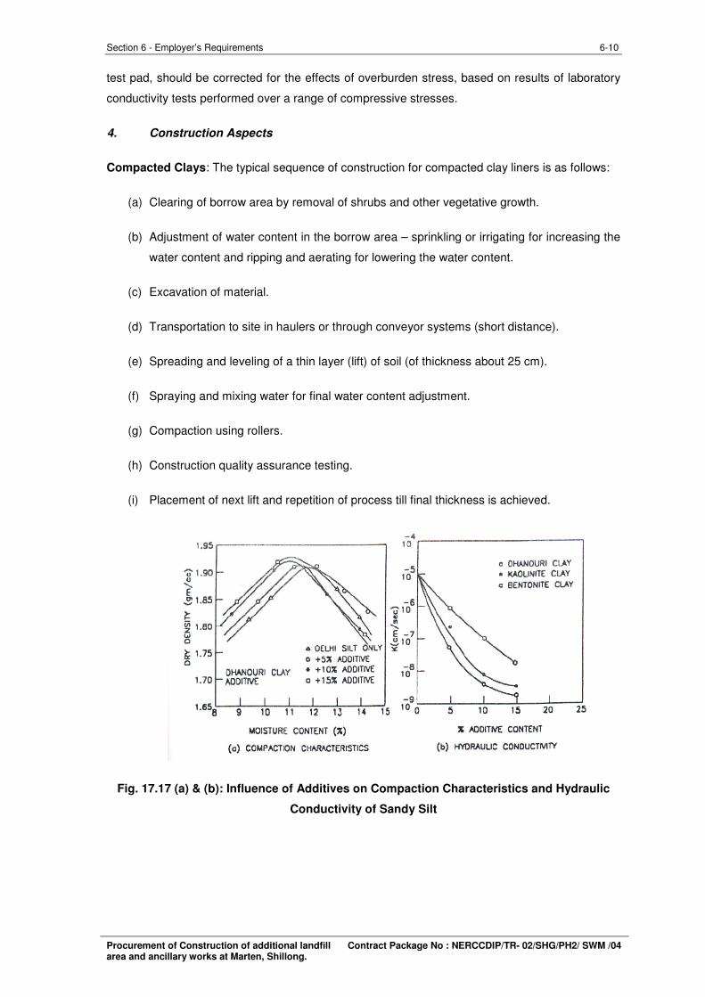
Soil-Additive Compaction Tests : Standard Proctor (or modified) tests are undertaken with
variable quantities of additives mixed to the soil, usually in increments of 2 to 5 percent. The
influence of the additive on dry density and optimum moisture content are evaluated[Fig. 17.27
(a)].
Soil-Additive Permeability Tests : Permeability tests are conducted on as compacted-then
saturated samples of amended soil with different percentages of additive, each sample
compacted to maximum density at optimum water content [Fig. 17.27(b)]. It is possible to identify
a minimum additive content, from a series of tests, which may be required to achieve the
desirable hydraulic conductivity.
Analysis of Laboratory Results :
Field engineers usually require a compaction specification, which states the minimum acceptable
dry density as well as the acceptable range of water content. It is usually possible to arrive at a
narrow acceptable range of water content and dry density as shown in Fig. 17.28. A step-by-step
process of elimination is to be adopted to identify this acceptable range of water content and dry
density, which should then be communicated to the field engineer.
3. Field Trial Test Pads
The construction of a field trial test pad prior to under taking construction of the main liner has
many advantages. One can experiment with compaction equipment, water content, number of
passes of the equipment, lift thickness and compactor speed. Most importantly, one can conduct
extensive testing, including quality control testing and hydraulic conductivity tests, on the test pad.
The test pad should have a width which is significantly more than the width of the construction
vehicles (>10 m) and greater length. The pad should ideally be the same thickness as the full-
sized liner, but may sometimes be thinner. The in-situ hydraulic conductivity may be determined
by the sealed double ring infiltrometer method. In in-situ tests on test pads, the hydraulic
conductivity is measured under zero over burden stress. Hydraulic conductivity measured on a
Procurement of Construction of additional landfill Contract Package No : NERCCDIP/TR- 02/SHG/PH2/ SWM /04 area and ancillary works at Marten, Shillong.
6-10 Section 6 - Employer’s Requirements
test pad, should be corrected for the effects of overburden stress, based on results of laboratory
conductivity tests performed over a range of compressive stresses.
4. Construction Aspects
Compacted Clays: The typical sequence of construction for compacted clay liners is as follows:
(a) Clearing of borrow area by removal of shrubs and other vegetative growth.
(b) Adjustment of water content in the borrow area – sprinkling or irrigating for increasing the
water content and ripping and aerating for lowering the water content.
(c) Excavation of material.
(d) Transportation to site in haulers or through conveyor systems (short distance).
(e) Spreading and leveling of a thin layer (lift) of soil (of thickness about 25 cm).
(f) Spraying and mixing water for final water content adjustment.
(g) Compaction using rollers.
(h) Construction quality assurance testing.
(i) Placement of next lift and repetition of process till final thickness is achieved.
Fig. 17.17 (a) & (b): Influence of Additives on Compaction Characteristics and Hydraulic
Conductivity of Sandy Silt
Procurement of Construction of additional landfill Contract Package No : NERCCDIP/TR- 02/SHG/PH2/ SWM /04 area and ancillary works at Marten, Shillong.
6-11 Section 6 - Employer’s Requirements
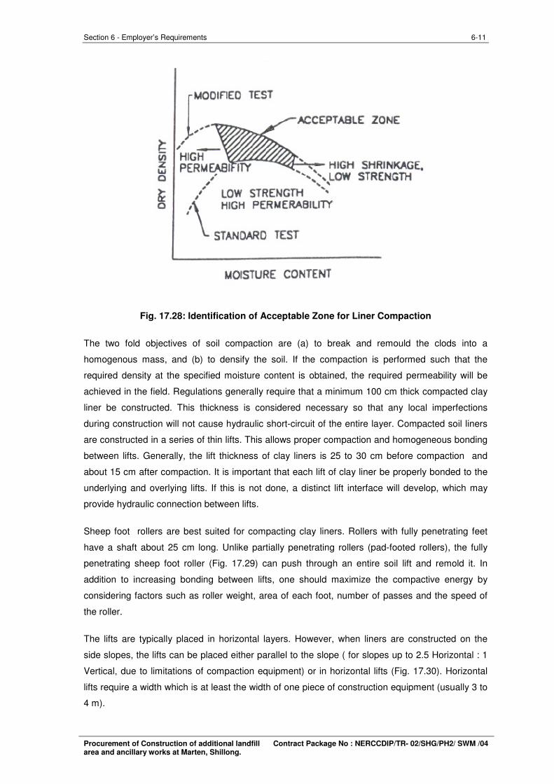
Fig. 17.28: Identification of Acceptable Zone for Liner Compaction
The two fold objectives of soil compaction are (a) to break and remould the clods into a
homogenous mass, and (b) to densify the soil. If the compaction is performed such that the
required density at the specified moisture content is obtained, the required permeability will be
achieved in the field. Regulations generally require that a minimum 100 cm thick compacted clay
liner be constructed. This thickness is considered necessary so that any local imperfections
during construction will not cause hydraulic short-circuit of the entire layer. Compacted soil liners
are constructed in a series of thin lifts. This allows proper compaction and homogeneous bonding
between lifts. Generally, the lift thickness of clay liners is 25 to 30 cm before compaction and
about 15 cm after compaction. It is important that each lift of clay liner be properly bonded to the
underlying and overlying lifts. If this is not done, a distinct lift interface will develop, which may
provide hydraulic connection between lifts.
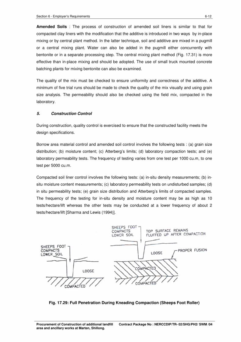
Sheep foot rollers are best suited for compacting clay liners. Rollers with fully penetrating feet
have a shaft about 25 cm long. Unlike partially penetrating rollers (pad-footed rollers), the fully
penetrating sheep foot roller (Fig. 17.29) can push through an entire soil lift and remold it. In
addition to increasing bonding between lifts, one should maximize the compactive energy by
considering factors such as roller weight, area of each foot, number of passes and the speed of
the roller.
The lifts are typically placed in horizontal layers. However, when liners are constructed on the
side slopes, the lifts can be placed either parallel to the slope ( for slopes up to 2.5 Horizontal : 1
Vertical, due to limitations of compaction equipment) or in horizontal lifts (Fig. 17.30). Horizontal
lifts require a width which is at least the width of one piece of construction equipment (usually 3 to
4 m).
Procurement of Construction of additional landfill Contract Package No : NERCCDIP/TR- 02/SHG/PH2/ SWM /04 area and ancillary works at Marten, Shillong.
6-12 Section 6 - Employer’s Requirements
Amended Soils : The process of construction of amended soil liners is similar to that for
compacted clay liners with the modification that the additive is introduced in two ways by in-place
mixing or by central plant method. In the latter technique, soil and additive are mixed in a pugmill
or a central mixing plant. Water can also be added in the pugmill either concurrently with
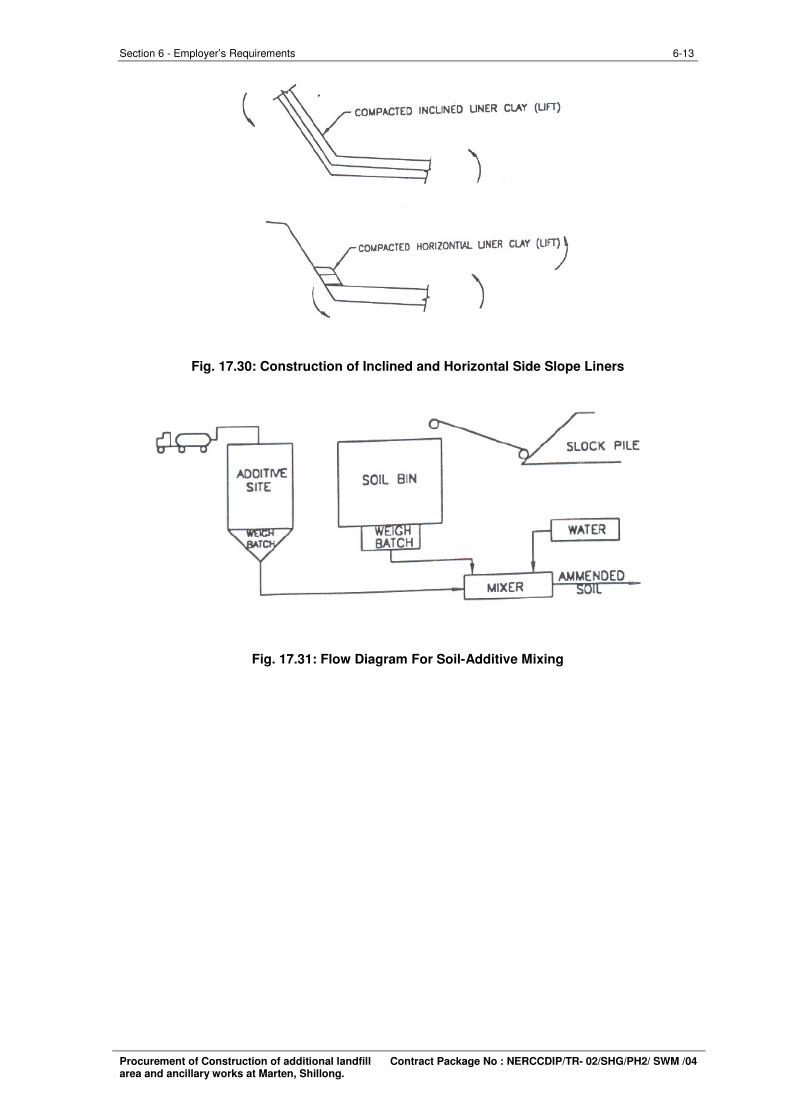
bentonite or in a separate processing step. The central mixing plant method (Fig. 17.31) is more
effective than in-place mixing and should be adopted. The use of small truck mounted concrete
batching plants for mixing bentonite can also be examined.
The quality of the mix must be checked to ensure uniformity and correctness of the additive. A
minimum of five trial runs should be made to check the quality of the mix visually and using grain
size analysis. The permeability should also be checked using the field mix, compacted in the
laboratory.
5. Construction Control
During construction, quality control is exercised to ensure that the constructed facility meets the
design specifications.
Borrow area material control and amended soil control involves the following tests : (a) grain size
distribution; (b) moisture content; (c) Atterberg’s limits; (d) laboratory compaction tests; and (e)
laboratory permeability tests. The frequency of testing varies from one test per 1000 cu.m, to one
test per 5000 cu.m.
Compacted soil liner control involves the following tests: (a) in-situ density measurements; (b) in-
situ moisture content measurements; (c) laboratory permeability tests on undisturbed samples; (d)
in situ permeability tests; (e) grain size distribution and Atterberg’s limits of compacted samples.
The frequency of the testing for in-situ density and moisture content may be as high as 10
tests/hectare/lift whereas the other tests may be conducted at a lower frequency of about 2
tests/hectare/lift [Sharma and Lewis (1994)].
Fig. 17.29: Full Penetration During Kneading Compaction (Sheeps Foot Roller)
Procurement of Construction of additional landfill Contract Package No : NERCCDIP/TR- 02/SHG/PH2/ SWM /04 area and ancillary works at Marten, Shillong.
6-13 Section 6 - Employer’s Requirements
Fig. 17.30: Construction of Inclined and Horizontal Side Slope Liners
Fig. 17.31: Flow Diagram For Soil-Additive Mixing
Procurement of Construction of additional landfill Contract Package No : NERCCDIP/TR- 02/SHG/PH2/ SWM /04 area and ancillary works at Marten, Shillong.
6-14 Section 6 - Employer’s Requirements
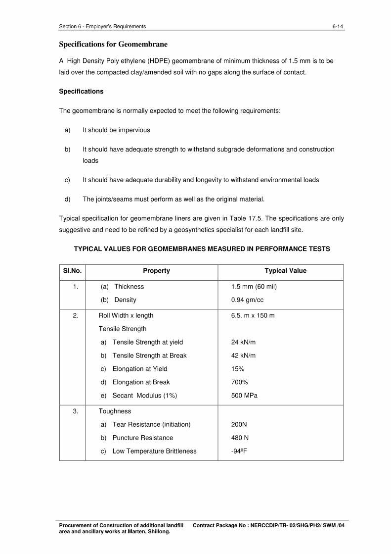
Specifications for Geomembrane
A High Density Poly ethylene (HDPE) geomembrane of minimum thickness of 1.5 mm is to be
laid over the compacted clay/amended soil with no gaps along the surface of contact.
Specifications
The geomembrane is normally expected to meet the following requirements:
a) It should be impervious
b) It should have adequate strength to withstand subgrade deformations and construction
loads
c) It should have adequate durability and longevity to withstand environmental loads
d) The joints/seams must perform as well as the original material.
Typical specification for geomembrane liners are given in Table 17.5. The specifications are only
suggestive and need to be refined by a geosynthetics specialist for each landfill site.
TYPICAL VALUES FOR GEOMEMBRANES MEASURED IN PERFORMANCE TESTS
Sl.No. Property Typical Value
1. (a) Thickness
(b) Density
1.5 mm (60 mil)
0.94 gm/cc
2. Roll Width x length
Tensile Strength
a) Tensile Strength at yield
b) Tensile Strength at Break
c) Elongation at Yield
d) Elongation at Break
e) Secant Modulus (1%)
6.5. m x 150 m
24 kN/m
42 kN/m
15%
700%
500 MPa
3. Toughness
a) Tear Resistance (initiation)
b) Puncture Resistance
c) Low Temperature Brittleness
200N
480 N
-94ºF
Procurement of Construction of additional landfill Contract Package No : NERCCDIP/TR- 02/SHG/PH2/ SWM /04 area and ancillary works at Marten, Shillong.
6-15 Section 6 - Employer’s Requirements
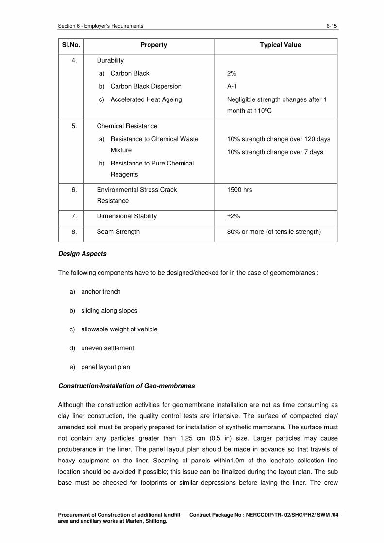
Sl.No. Property Typical Value
4. Durability
a) Carbon Black
b) Carbon Black Dispersion
c) Accelerated Heat Ageing
2%
A-1
Negligible strength changes after 1
month at 110ºC
5. Chemical Resistance
a) Resistance to Chemical Waste
Mixture
b) Resistance to Pure Chemical
Reagents
10% strength change over 120 days
10% strength change over 7 days
6. Environmental Stress Crack
Resistance
1500 hrs
7. Dimensional Stability ±2%
8. Seam Strength 80% or more (of tensile strength)
Design Aspects
The following components have to be designed/checked for in the case of geomembranes :
a) anchor trench
b) sliding along slopes
c) allowable weight of vehicle
d) uneven settlement
e) panel layout plan
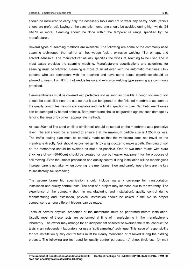
Construction/Installation of Geo-membranes
Although the construction activities for geomembrane installation are not as time consuming as
clay liner construction, the quality control tests are intensive. The surface of compacted clay/
amended soil must be properly prepared for installation of synthetic membrane. The surface must
not contain any particles greater than 1.25 cm (0.5 in) size. Larger particles may cause
protuberance in the liner. The panel layout plan should be made in advance so that travels of
heavy equipment on the liner. Seaming of panels within1.0m of the leachate collection line
location should be avoided if possible; this issue can be finalized during the layout plan. The sub
base must be checked for footprints or similar depressions before laying the liner. The crew
Procurement of Construction of additional landfill Contract Package No : NERCCDIP/TR- 02/SHG/PH2/ SWM /04 area and ancillary works at Marten, Shillong.
6-16 Section 6 - Employer’s Requirements
should be instructed to carry only the necessary tools and not to wear any heavy boots (teninis
shoes are preferred). Laying of the synthetic membrane should be avoided during high winds [24
KMPH or more]. Seaming should be done within the temperature range specified by the
manufacturer.
Several types of seaming methods are available. The following are some of the commonly used
seaming techniques: thermal-hot air, hot wedge fusion, extrusion welding (fillet or lap), and
solvent adhesive. The manufacturer usually specifies the types of seaming to be used and in
most cases provides the seaming machine. Manufacturer’s specifications and guidelines for
seaming must be followed. Seaming is more of an art even with the automatic machines. Only
persons who are conversant with the machine and have some actual experience should be
allowed to seam. For HDPE, hot wedge fusion and extrusion welding type seaming are commonly
practiced.
Geo-membranes must be covered with protective soil as soon as possible. Enough volume of soil
should be stockpiled near the site so that it can be spread on the finished membrane as soon as
the quality control test results are available and the final inspection is over. Synthetic membranes
can be damaged by hoofed animals. Bare membrane should be guarded against such damage by
fencing the area or by other appropriate methods.
At least 30cm of fine sand or silt or similar soil should be spread on the membrane as a protective
layer. The soil should be screened to ensure that the maximum particle size is 1.25cm or less.
The traffic routing plan must be carefully made so that the vehicle(s) does not travel on the
membrane directly. Soil should be pushed gently by a light dozer to make a path. Dumping of soil
on the membrane should be avoided as much as possible. One or two main routes with extra
thickness of soil (60-90cm) should be created for use by heavier equipment for the proposes of
soil moving .Even the utmost precaution and quality control during installation will be meaningless
if proper care is not taken when covering the membrane. Slow and careful operations are the key
to satisfactory soil spreading.
The geomembrane bid specification should include warranty coverage for transportation
installation and quality control tests. The cost of a project may increase due to the warranty. The
experience of the company (both in manufacturing and installation), quality control during
manufacturing and installation, physical installation should be asked in the bid so proper
comparisons among different bidders can be made.
Tests of several physical properties of the membrane must be performed before installation.
Usually most of these tests are performed at time of manufacturing in the manufacturer’s
laboratory. The owner may arrange for an independent observer to oversee the tests, conduct the
tests in an independent laboratory, or use a “split sampling” technique. This issue of responsibility
for pre installation quality control tests must be clearly mentioned or resolved during the bidding
process. The following are test used for quality control purposes: (a) sheet thickness, (b) melt
Procurement of Construction of additional landfill Contract Package No : NERCCDIP/TR- 02/SHG/PH2/ SWM /04 area and ancillary works at Marten, Shillong.
6-17 Section 6 - Employer’s Requirements
index,(c) percentage carbon black,(d) puncture resistance,(e) tear resistance, (f) dimensional
stability,(g) density,(h) low temperature brittleness, (i) peel adhesion, and (j) bonded seam
strength.
The quality control tests that are performed during installation include the following:
(a) Inspection of surface of compacted clay/ amended soil layer.
(b) Verification of the proposed layout plan.
(c) Check roll overlap.
(d) Checking anchoring trench and sump.
(e) Testing of all factory and field seams using proper techniques over full length.
(f) Destructive seam strength test.
(g) Patch up repair.
All the HDPE pipes and liner materials shall be procured from an approved manufacturer by the
Project Manager and the Contractor shall submit the procurement details along with QAP for
approval of SIPMIU for all the materials to the Project Manager before procurement of the same.
The Quality control procedures to be conducted at the manufacturing plant by third party
inspection team appointed by SIPMIU for the purpose. The manufacturers test certificates and
the tested batch details to be provided as detailed in the approved QAP.
Procurement of Construction of additional landfill Contract Package No : NERCCDIP/TR- 02/SHG/PH2/ SWM /04 area and ancillary works at Marten, Shillong.
6-18 Section 6 - Employer’s Requirements
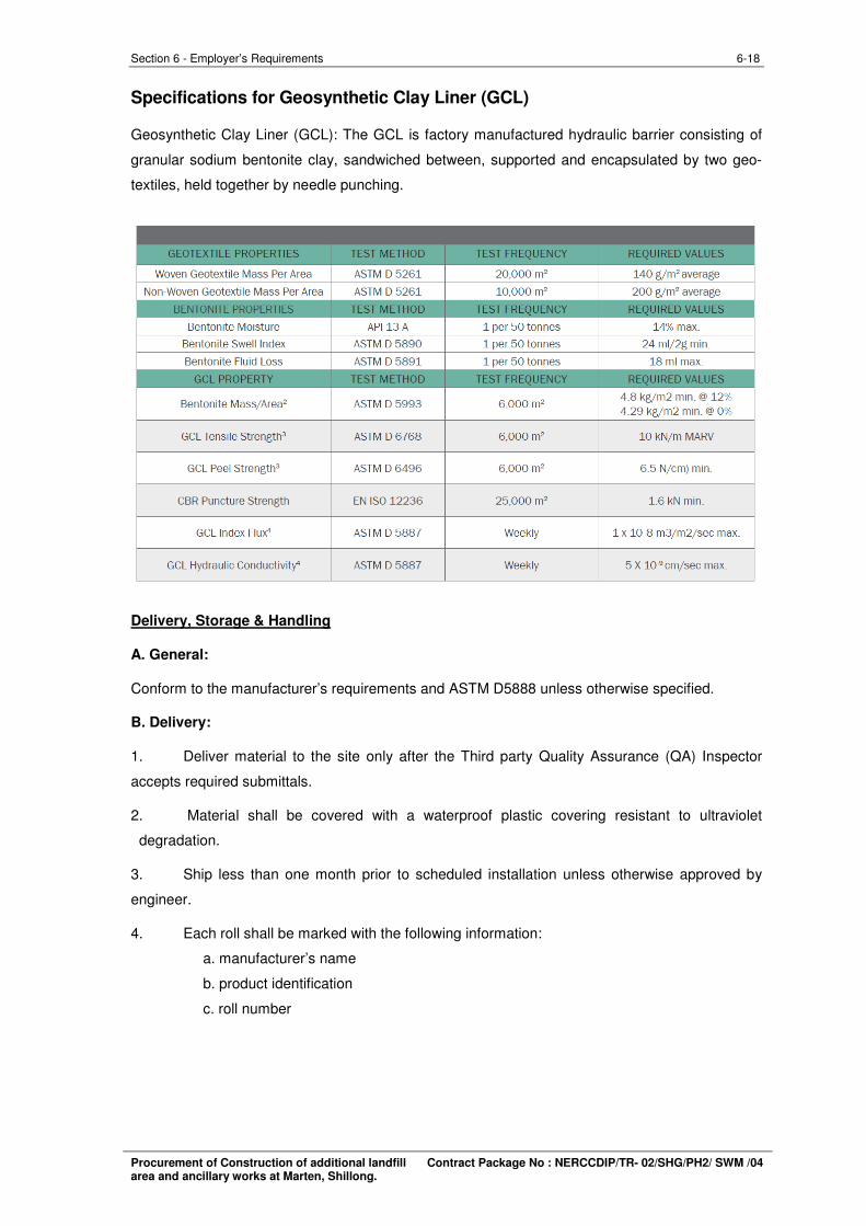
Specifications for Geosynthetic Clay Liner (GCL)
Geosynthetic Clay Liner (GCL): The GCL is factory manufactured hydraulic barrier consisting of
granular sodium bentonite clay, sandwiched between, supported and encapsulated by two geo
textiles, held together by needle punching.
Delivery, Storage & Handling
A. General:
Conform to the manufacturer’s requirements and ASTM D5888 unless otherwise specified.
B. Delivery:
1. Deliver material to the site only after the Third party Quality Assurance (QA) Inspector
accepts required submittals.
2. Material shall be covered with a waterproof plastic covering resistant to ultraviolet
degradation.
3. Ship less than one month prior to scheduled installation unless otherwise approved by
engineer.
4. Each roll shall be marked with the following information:
a. manufacturer’s name
b. product identification
c. roll number
Procurement of Construction of additional landfill Contract Package No : NERCCDIP/TR- 02/SHG/PH2/ SWM /04 area and ancillary works at Marten, Shillong.
6-19 Section 6 - Employer’s Requirements
C. Handling:
The TPQA inspector shall verify that proper handling equipment exists which does not pose any
danger to installation personnel or risk of damage or deformation to the liner material itself.
Suitable handling equipment is described below:
Spreader Bar Assembly - A spreader bar assembly shall include both a core pipe or bar and a
spreader bar beam. The core pipe shall be used to uniformly support the roll when inserted
through the GCL core while the spreader bar beam will prevent chains or straps from chafing the
roll edges.
• Stinger - A stinger is a rigid pipe or rod with one end directly connected to a forklift or
other handling equipment. If a stinger is used, it should be fully inserted to its full length
into the roll to prevent excessive bending of the roll when lifted.
• Roller Cradles - Roller cradles consist of two large diameter rollers spaced approximately
3 inches apart, which both support the GCL roll and allows it to freely unroll. The use of
roller cradles shall be permitted if the rollers support the entire width of the GCL roll.
• Straps – A properly structured and supported pole or “carpet puller” can be used to
unload GCL rolls onsite. As an alternative, straps that are appropriately rated can be used
as an approved lifting method to unload GCL rolls.
D. Storage:
1. Store rolls in space allocated by Project Manager. Space should be at high ground level
or elevated above ground surface.
2. Stack no more than 3 rolls high.
3. Protect rolls from UV, precipitation, other sources of moisture, mud, dirt, dust, puncture,
cutting or any other damaging or deleterious conditions.
4. An additional tarpaulin or plastic sheet shall be used over the stacked rolls to provide
extra protection for GCL material stored outdoors.
5. Preserve integrity and readability of roll labels.
6. Bagged bentonite material shall be stored and tarped next to GCL rolls unless other more
protective measures are available. Bags shall be stored on pallets or other suitably dry
surface which will prevent undue prehydration.
E. GCL Inspection upon Delivery:
1. Each roll shall be visually inspected when unloaded to determine if any packaging or
material has been damaged during transit.
2. Repairs to damaged GCL shall be performed as per standard specification.
a. Rolls exhibiting damage shall be marked and set aside for closer examination
during deployment.
b. Minor rips or tears in the plastic packaging shall be repaired with moisture
resistant tape prior to being placed in storage to prevent moisture damage.
c. GCL rolls delivered to the project site shall be only those indicated on GCL
manufacturing quality control certificates.
Procurement of Construction of additional landfill Contract Package No : NERCCDIP/TR- 02/SHG/PH2/ SWM /04 area and ancillary works at Marten, Shillong.
6-20 Section 6 - Employer’s Requirements
d. For needle punched GCLs, the presence of free-flowing water within the
packaging shall require that roll to be set aside for further examination to
ascertain the extent of damage, if any. Free-flowing water within the packaging of
unreinforced GCLs shall be cause for rejection of that roll.
Product Qualifications:
• The GCL product supplied to the project shall be in full accordance with the requirements
of this section.
• The GCL shall be manufactured by mechanically bonding the geo-textiles using a needle
punching process as described in Section 1.3 to enhance frictional and internal shear
strength characteristics.
• The needle punched GCL shall thermally heat set the nonwoven fibers where they
protrude from the second geotextile (woven or nonwoven depending upon product) to
more permanently secure the reinforcement in place. Other means may be used to lock
the fibers in place if the process demonstrates similar performance to the thermal heat set
process.
• In order to maintain these characteristics, no glues, adhesives or other non-mechanical
bonding processes shall be used in lieu of the needle punch process. Their use to
enhance the physical properties of the GCL is permitted.
All the HDPE pipes and liner materials shall be procured from an approved manufacturer by the
Project Manager and the Contractor shall submit the procurement details along with QAP for
approval of SIPMIU for all the materials to the Project Manager before procurement of the same.
The Quality control procedures to be conducted at the manufacturing plant by third party
inspection team appointed by SIPMIU for the purpose. The manufacturers test certificates and
the tested batch details to be provided as detailed in the approved QAP.
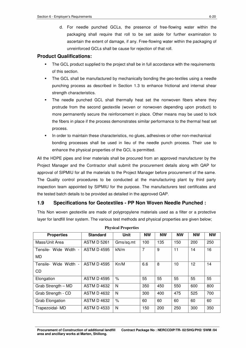
1.9 Specifications for Geotextiles - PP Non Woven Needle Punched :
This Non woven geotextile are made of polypropylene materials used as a filter or a protective
layer for landfill liner system. The various test methods and physical properties are given below;
Physical Properties
Properties Standard Unit NW NW NW NW NW
Mass/Unit Area ASTM D 5261 Gms/sq.mt 100 135 150 200 250
Tensile- Wide Width
MD
- ASTM D 4595 kN/m 7 9 11 14 16
Tensile- Wide Width
CD
- ASTM D 4595 Kn/M 6.6 8 10 12 14
Elongation ASTM D 4595 % 55 55 55 55 55
Grab Strength – MD ASTM D 4632 N 350 450 550 600 800
Grab Strength - CD ASTM D 4632 N 300 400 475 525 700
Grab Elongation ASTM D 4632 % 60 60 60 60 60
Trapezoidal- MD ASTM D 4533 N 150 200 250 300 350
Procurement of Construction of additional landfill Contract Package No : NERCCDIP/TR- 02/SHG/PH2/ SWM /04 area and ancillary works at Marten, Shillong.
6-21 Section 6 - Employer’s Requirements
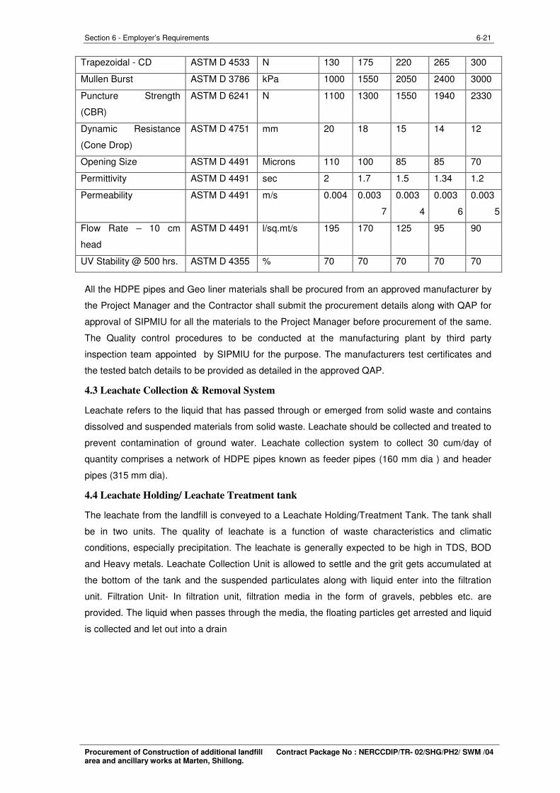
Trapezoidal - CD ASTM D 4533 N 130 175 220 265 300
Mullen Burst ASTM D 3786 kPa 1000 1550 2050 2400 3000
Puncture Strength
(CBR)
ASTM D 6241 N 1100 1300 1550 1940 2330
Dynamic Resistance
(Cone Drop)
ASTM D 4751 mm 20 18 15 14 12
Opening Size ASTM D 4491 Microns 110 100 85 85 70
Permittivity ASTM D 4491 sec 2 1.7 1.5 1.34 1.2
Permeability ASTM D 4491 m/s 0.004 0.003
7
0.003
4
0.003
6
0.003
5
Flow Rate – 10 cm
head
ASTM D 4491 l/sq.mt/s 195 170 125 95 90
UV Stability @ 500 hrs. ASTM D 4355 % 70 70 70 70 70
All the HDPE pipes and Geo liner materials shall be procured from an approved manufacturer by
the Project Manager and the Contractor shall submit the procurement details along with QAP for
approval of SIPMIU for all the materials to the Project Manager before procurement of the same.
The Quality control procedures to be conducted at the manufacturing plant by third party
inspection team appointed by SIPMIU for the purpose. The manufacturers test certificates and
the tested batch details to be provided as detailed in the approved QAP.
4.3 Leachate Collection & Removal System
Leachate refers to the liquid that has passed through or emerged from solid waste and contains
dissolved and suspended materials from solid waste. Leachate should be collected and treated to
prevent contamination of ground water. Leachate collection system to collect 30 cum/day of
quantity comprises a network of HDPE pipes known as feeder pipes (160 mm dia ) and header
pipes (315 mm dia).
4.4 Leachate Holding/ Leachate Treatment tank
The leachate from the landfill is conveyed to a Leachate Holding/Treatment Tank. The tank shall
be in two units. The quality of leachate is a function of waste characteristics and climatic
conditions, especially precipitation. The leachate is generally expected to be high in TDS, BOD
and Heavy metals. Leachate Collection Unit is allowed to settle and the grit gets accumulated at
the bottom of the tank and the suspended particulates along with liquid enter into the filtration
unit. Filtration Unit- In filtration unit, filtration media in the form of gravels, pebbles etc. are
provided. The liquid when passes through the media, the floating particles get arrested and liquid
is collected and let out into a drain
Procurement of Construction of additional landfill Contract Package No : NERCCDIP/TR- 02/SHG/PH2/ SWM /04 area and ancillary works at Marten, Shillong.
6-22 Section 6 - Employer’s Requirements
Drawings (Vol II)
Drawings have been provided separately as Volume II
2.1.1. Employer’s Drawings:-The drawings listed in the Tender document are Employer’s
drawings and are provided by the Employer as a guideline of the specifications and work. All data
and information furnished in the drawings by the Employer is given in good faith but the Employer
does not accept the responsibility for the completeness and accuracy thereof. The same shall be
verified by the contractor promptly pointing out errors or discrepancies thereof to the Engineer.
Drawings are provided as Volume 3 of the bid documents.
2.1.2. Contractor’s Drawings:-All drawings provided by the Contractor shall be on standard
size sheets, prepared on computer with Auto CAD Latest revision and shall show particulars in a
title block located in the lower right hand corner, in addition to the name of Contractor and
equipment manufacturer, date, scale, drawing, revision number (R0 for drawings submitted
initially, R1, R2 etc. for drawings submitted subsequently). A blank space shall be provided for the
Engineer’s approval stamp and provision shall be made for detail of revisions to be recorded. All
drawings submitted by the supplier shall use the English language. All drawings shall be clearly
and fully cross-referenced to the other drawings as relevant.
2.1.3. The Contractor’s attention is drawn to the Specification Document (Volume III) for
more information on the drawing requirement.
Procurement of Construction of additional landfill Contract Package No : NERCCDIP/TR- 02/SHG/PH2/ SWM /04 area and ancillary works at Marten, Shillong.
6-23 Section 6 - Employer’s Requirements
Supplementary Information
1.1.1. Co-operation: The Contractor shall establish full co-ordination with the officials of ULBs,
SIPMIU and the Programme Consultants and extend co-operation to complete work.
1.1.2. Records procedures and reports: A work order book shall be maintained by the
contractor at site/workshop for taking instructions from employer or his representative. The
Contractor shall maintain records pertaining to the quality of installation / erection work and
inspection, testing, compliance with all technical requirements in respect of all this works as
described before. The Contractor shall submit such records to the Employer after the completion
of any particular work before submitting the bill. The Contractor shall also maintain the cement/
steel consumption / material details etc. The Contractor shall proceed with Concrete works only
on approval of the pour card by the Project Manager.
1.1.3. Personnel:-The contractor shall depute sufficient staff to carry out installation, the
maintenance and repair work efficiently and satisfactorily. The Contractor shall undertake to
comply with applicable legislation and the code of labour law on matters of health, hygiene and
safety, and shall assume responsibility for works required in the event of any change in applicable
regulations. The contractor shall provide all necessary superintendence during the execution of
works and during maintenance. The Contractor’s staff shall include adequate and competent
persons with proven suitable, previous experience on similar contracts to supervise the works and
sufficient skilled, semi-skilled and unskilled labour to ensure completion of works in time. The
Contractor shall not remove any representative or skilled labour from the site without prior
approval of the Employer’s Representative for the proper fulfilling of the contractors obligations
under the contract. The contractor or a competent and authorized agent or representative
approved in writing by Employer on the basis of qualification and experience to be furnished by
the contractor, which approval may at any time be withdrawn, is to be constantly on the works and
shall give his whole time to the superintendence of the work.
1.1.4. Public Authorities: - The Contractor shall comply with all rules & regulations, bye laws
and directives given from time to time by any local or public authority in connection with this work
and shall himself pay fees or charges which are leviable on him without any extra cost.
1.1.5. Safety:-The Contractor will be responsible for safety of the material supplied and kept in
joint custody of the employer and the contractor till completion of contract. The Contractor shall at
his own expense arrange for the safety of his labour / supervisor staff employed by him directly or
indirectly for performing the work, as per statutory requirement. The Contractor shall report any
accident or unusual occurrence with the work at site that take place to employer immediately with
the action, which he might have taken.
1.1.6. Acquaintance with Site and Work Conditions:-The Bidder shall study the site and
general conditions in respect of approaches, labourers, climate and the data included in the
tender documents and get it verified with actual inspections of the site, before submitting the
Procurement of Construction of additional landfill Contract Package No : NERCCDIP/TR- 02/SHG/PH2/ SWM /04 area and ancillary works at Marten, Shillong.

6-24 Section 6 - Employer’s Requirements
tender. In case of doubt about any item or data included in the tender, the same shall be got
clarified in pre-bid meeting. Once the tender is accepted, it shall be concluded that the Contractor
has verified and made himself conversant with all the details required for completing the work as
stipulated conditions and specifications.
1.1.7. Store Shed Meter Repairs Shop, Office etc:-The Contractor shall make necessary
arrangement at his own cost for store shed, meter repairs shop/ office, meter test bench etc. The
Contractor shall consider all the costs related to required personnel, sheds, establishment of lab
and equipments in his quote and no costs /claim will be entertained in this regard.
1.1.8. Quality Control: This Section 6 shall be read in conjunction with the Standard
Specification provided along with Bid Document (Volume III).
Procurement of Construction of additional landfill Contract Package No : NERCCDIP/TR- 02/SHG/PH2/ SWM /04 area and ancillary works at Marten, Shillong.
-- ----
6-25 Section 6 - Employer’s Requirements
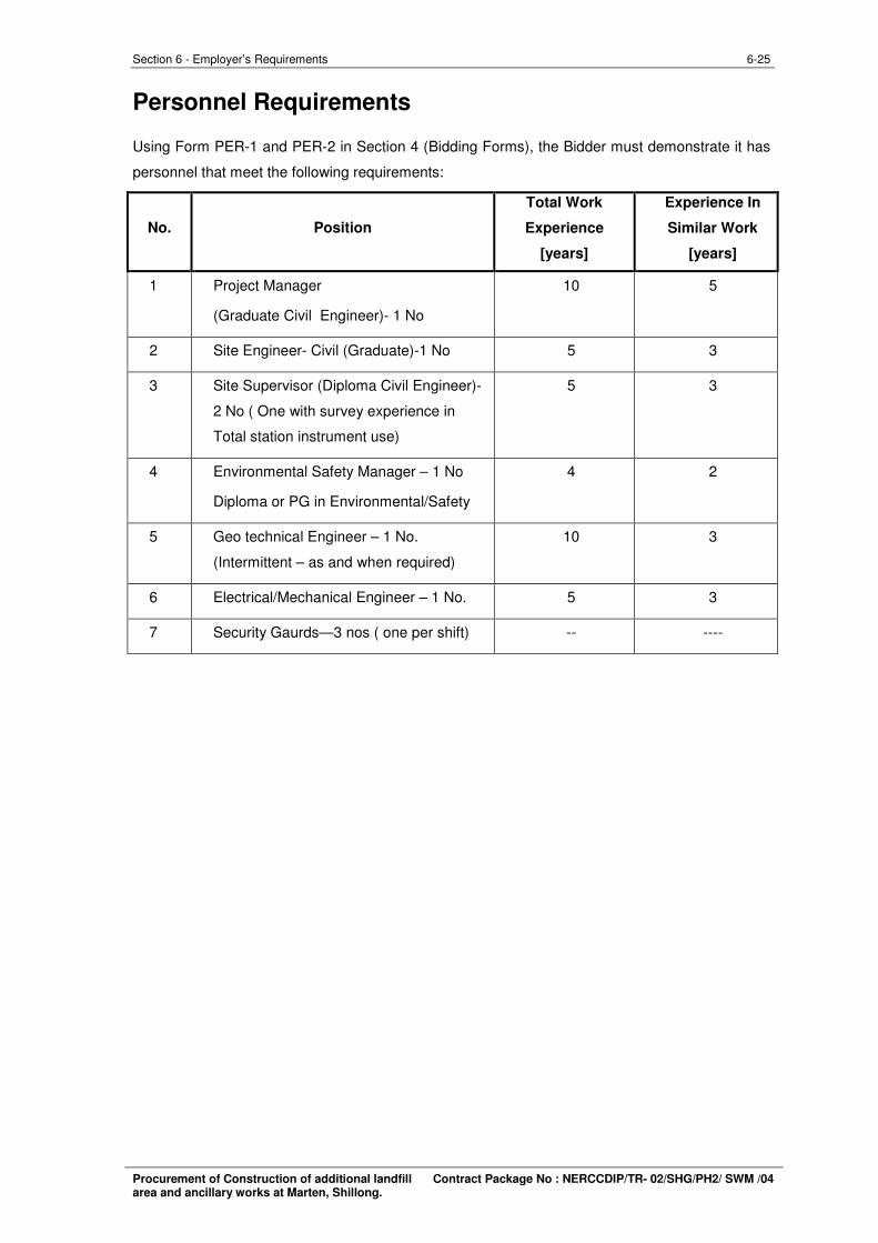
Personnel Requirements
Using Form PER-1 and PER-2 in Section 4 (Bidding Forms), the Bidder must demonstrate it has
personnel that meet the following requirements:
Total Work Experience In
No. Position Experience Similar Work
[years] [years]
1 Project Manager 10 5
(Graduate Civil Engineer)- 1 No
2 Site Engineer- Civil (Graduate)-1 No 5 3
3 Site Supervisor (Diploma Civil Engineer) 5 3
2 No ( One with survey experience in
Total station instrument use)
4 Environmental Safety Manager – 1 No 4 2
Diploma or PG in Environmental/Safety
5 Geo technical Engineer – 1 No. 10 3
(Intermittent – as and when required)
6 Electrical/Mechanical Engineer – 1 No. 5 3
7 Security Gaurds—3 nos ( one per shift)
Procurement of Construction of additional landfill Contract Package No : NERCCDIP/TR- 02/SHG/PH2/ SWM /04 area and ancillary works at Marten, Shillong.
6-26 Section 6 - Employer’s Requirements
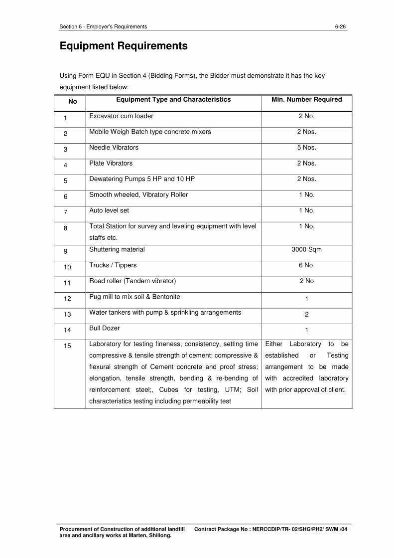
Equipment Requirements
Using Form EQU in Section 4 (Bidding Forms), the Bidder must demonstrate it has the key
equipment listed below:
No Equipment Type and Characteristics Min. Number Required
1 Excavator cum loader 2 No.
2 Mobile Weigh Batch type concrete mixers 2 Nos.
3 Needle Vibrators 5 Nos.
4 Plate Vibrators 2 Nos.
5 Dewatering Pumps 5 HP and 10 HP 2 Nos.
6 Smooth wheeled, Vibratory Roller 1 No.
7 Auto level set 1 No.
8 Total Station for survey and leveling equipment with level
staffs etc.
1 No.
9 Shuttering material 3000 Sqm
10 Trucks / Tippers 6 No.
11 Road roller (Tandem vibrator) 2 No
12 Pug mill to mix soil & Bentonite 1
13 Water tankers with pump & sprinkling arrangements 2
14 Bull Dozer 1
15 Laboratory for testing fineness, consistency, setting time
compressive & tensile strength of cement; compressive &
flexural strength of Cement concrete and proof stress;
elongation, tensile strength, bending & re-bending of
reinforcement steel;, Cubes for testing, UTM; Soil
characteristics testing including permeability test
Either Laboratory to be
established or Testing
arrangement to be made
with accredited laboratory
with prior approval of client.
Procurement of Construction of additional landfill Contract Package No : NERCCDIP/TR- 02/SHG/PH2/ SWM /04 area and ancillary works at Marten, Shillong.
6-27 Section 6 - Employer’s Requirements
Annexure I:
Procurement of Construction of additional landfill Contract Package No : NERCCDIP/TR- 02/SHG/PH2/ SWM /04 area and ancillary works at Marten, Shillong.
6-28 Section 6 - Employer’s Requirements
Procurement of Construction of additional landfill Contract Package No : NERCCDIP/TR- 02/SHG/PH2/ SWM /04 area and ancillary works at Marten, Shillong.
6-29 Section 6 - Employer’s Requirements
Procurement of Construction of additional landfill Contract Package No : NERCCDIP/TR- 02/SHG/PH2/ SWM /04 area and ancillary works at Marten, Shillong.
6-30 Section 6 - Employer’s Requirements
Procurement of Construction of additional landfill Contract Package No : NERCCDIP/TR- 02/SHG/PH2/ SWM /04 area and ancillary works at Marten, Shillong.
6-31 Section 6 - Employer’s Requirements
Procurement of Construction of additional landfill Contract Package No : NERCCDIP/TR- 02/SHG/PH2/ SWM /04 area and ancillary works at Marten, Shillong.
6-32 Section 6 - Employer’s Requirements
Procurement of Construction of additional landfill Contract Package No : NERCCDIP/TR- 02/SHG/PH2/ SWM /04 area and ancillary works at Marten, Shillong.
6-33 Section 6 - Employer’s Requirements
Procurement of Construction of additional landfill Contract Package No : NERCCDIP/TR- 02/SHG/PH2/ SWM /04 area and ancillary works at Marten, Shillong.
6-34 Section 6 - Employer’s Requirements
Procurement of Construction of additional landfill Contract Package No : NERCCDIP/TR- 02/SHG/PH2/ SWM /04 area and ancillary works at Marten, Shillong.
6-35 Section 6 - Employer’s Requirements
Procurement of Construction of additional landfill Contract Package No : NERCCDIP/TR- 02/SHG/PH2/ SWM /04 area and ancillary works at Marten, Shillong.
6-36 Section 6 - Employer’s Requirements
Procurement of Construction of additional landfill Contract Package No : NERCCDIP/TR- 02/SHG/PH2/ SWM /04 area and ancillary works at Marten, Shillong.
6-37 Section 6 - Employer’s Requirements
Procurement of Construction of additional landfill Contract Package No : NERCCDIP/TR- 02/SHG/PH2/ SWM /04 area and ancillary works at Marten, Shillong.
6-38 Section 6 - Employer’s Requirements
Procurement of Construction of additional landfill Contract Package No : NERCCDIP/TR- 02/SHG/PH2/ SWM /04 area and ancillary works at Marten, Shillong.
6-39 Section 6 - Employer’s Requirements
Procurement of Construction of additional landfill Contract Package No : NERCCDIP/TR- 02/SHG/PH2/ SWM /04 area and ancillary works at Marten, Shillong.
6-40 Section 6 - Employer’s Requirements
Procurement of Construction of additional landfill Contract Package No : NERCCDIP/TR- 02/SHG/PH2/ SWM /04 area and ancillary works at Marten, Shillong.
6-41 Section 6 - Employer’s Requirements
Procurement of Construction of additional landfill Contract Package No : NERCCDIP/TR- 02/SHG/PH2/ SWM /04 area and ancillary works at Marten, Shillong.
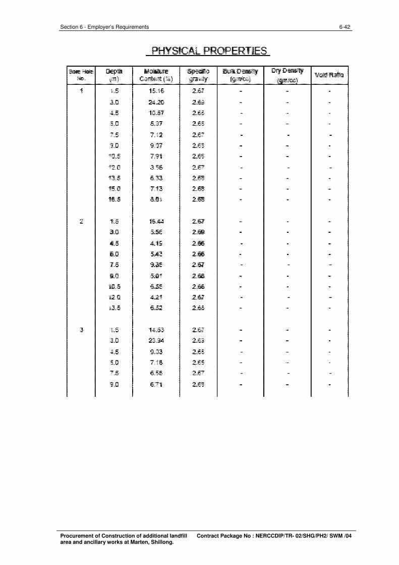
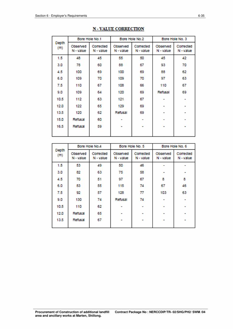
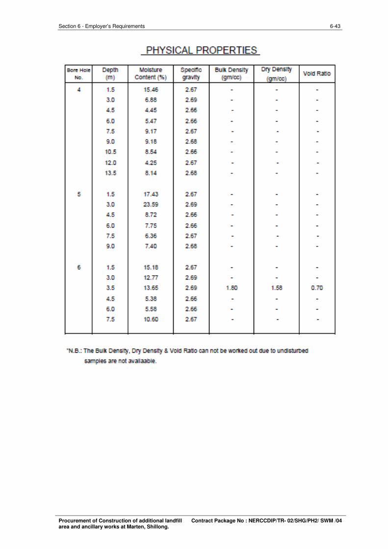
PHYSICAL PROPERTIES
lil<l<l,Hn Dfp111 ~ Bu•--··~~x ory , 'llllltl Rilll:11
NI,, jm) C Dll«!l'!t ('Iii) ,;µ\lily 1-'00l -1.5 1!L16 2,1,:; - - . J.!l 24.20 :2_69 - - .
4.5 HUi7 2.611 . .. -5.!l 5.97 2.611 . . -7.5 7.12 2.57 . . .
'lUl 9.117 2.611 . - . i!l.5 7.91 2.611 . . .
1:!J] J.56 2.57 . . .
13.5 5.33 2.611 . . . 15.a 7.13 2.611 . - .
1!i.5 a.a1 2.611 . . .
2 1.5 16.44 2.57 . .• . J.a 5.55 2.5!1 . . . 4.5 .ii.HI 2.65 . . . !:W 5.43 2.611 . . . 7.5 9.35 2.57 . . .
9.a 5.a1 2.611 . . .
10.5 5.55 2.55 . . .
i:2.0 4.21 2.67 . . .
1J.5 5.52 2.56 . . .
3 1.5 14.63 2.57 - - .
J.a 23.94 2.5!1 . . .
4.5 9.03 ;2_66 . . .
Ei.ll 7.HI 2.611 . .. -1.5 6.55 :2_67 . . .
9.ll 6.71 2.611 . . .
6-42 Section 6 - Employer’s Requirements
Procurement of Construction of additional landfill Contract Package No : NERCCDIP/TR- 02/SHG/PH2/ SWM /04 area and ancillary works at Marten, Shillong.
6-43 Section 6 - Employer’s Requirements
Procurement of Construction of additional landfill Contract Package No : NERCCDIP/TR- 02/SHG/PH2/ SWM /04 area and ancillary works at Marten, Shillong.
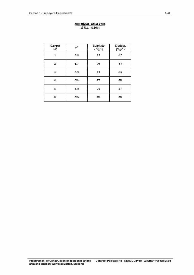
"
NO
.:l
3
4
5
6
CHEIIICAI.. AMAi.. YUi ilitG.l..·IUilllm
imimm
fi.i 72
fi.7 7fi
fi.!I 7!1
li.5 Tl
Ii.II 19
li.!I 111
CK!ff41!!; mlal"1"1
67
34
fifi
.it\
51
.&,
6-44 Section 6 - Employer’s Requirements
Procurement of Construction of additional landfill Contract Package No : NERCCDIP/TR- 02/SHG/PH2/ SWM /04 area and ancillary works at Marten, Shillong.
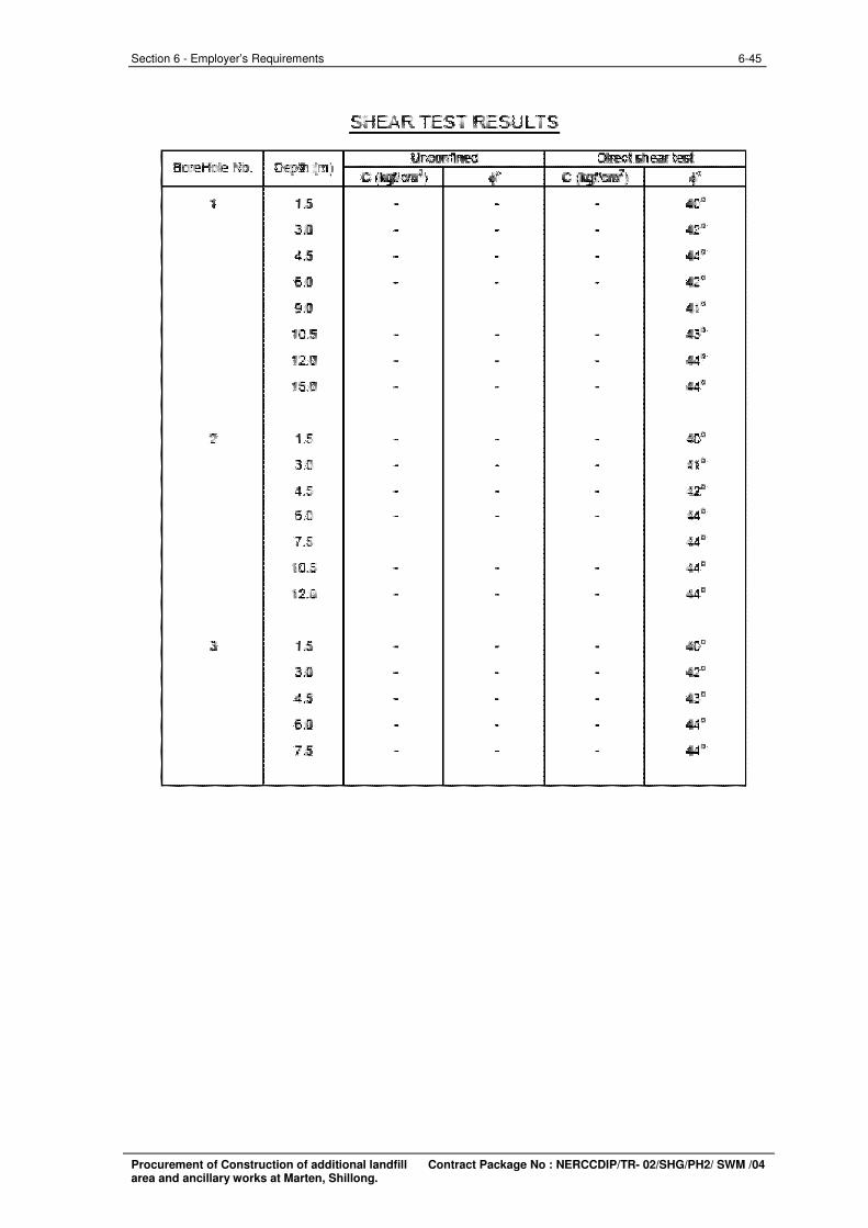
BoreHl:iie No. Ul'IOOMflfll!d Dlll!lll dle.ir lll!l;t
c I lrl c ' •• 1 1.5 - - - 40"
2UI - - - 42"
4.5 - - - 4140
15.0 - - - 412"
!i.O
1115 - - - .u• 12.[l - - - 414a
15,[l - - - 414a
::! 1.5 - - -11.0 - - -4.5 - - -15,0 - - - 4140
7.5 4140
Ul.5 - - -12J) - - - 414a
3 1.5 - - - 40a
11.0 - - - 412"
4,5 - - - 410
6.0 - - -7,5 - - -
6-45 Section 6 - Employer’s Requirements
Procurement of Construction of additional landfill Contract Package No : NERCCDIP/TR- 02/SHG/PH2/ SWM /04 area and ancillary works at Marten, Shillong.
6-46 Section 6 - Employer’s Requirements
Procurement of Construction of additional landfill Contract Package No : NERCCDIP/TR- 02/SHG/PH2/ SWM /04 area and ancillary works at Marten, Shillong.
6-47 Section 6 - Employer’s Requirements
Procurement of Construction of additional landfill Contract Package No : NERCCDIP/TR- 02/SHG/PH2/ SWM /04 area and ancillary works at Marten, Shillong.
6-48 Section 6 - Employer’s Requirements
Procurement of Construction of additional landfill Contract Package No : NERCCDIP/TR- 02/SHG/PH2/ SWM /04 area and ancillary works at Marten, Shillong.
6-49 Section 6 - Employer’s Requirements
Procurement of Construction of additional landfill area and ancillary works at Marten, Shillong. Contract Package No : NERCCDIP/TR- 02/SHG/PH2/ SWM /04
6-50 Section 6 - Employer’s Requirements
Procurement of Construction of additional landfill area and ancillary works at Marten, Shillong. Contract Package No : NERCCDIP/TR- 02/SHG/PH2/ SWM /04
6-51 Section 6 - Employer’s Requirements
Procurement of Construction of additional landfill area and ancillary works at Marten, Shillong. Contract Package No : NERCCDIP/TR- 02/SHG/PH2/ SWM /04
6-52 Section 6 - Employer’s Requirements
Procurement of Construction of additional landfill area and ancillary works at Marten, Shillong. Contract Package No : NERCCDIP/TR- 02/SHG/PH2/ SWM /04
6-53 Section 6 - Employer’s Requirements
Procurement of Construction of additional landfill area and ancillary works at Marten, Shillong. Contract Package No : NERCCDIP/TR- 02/SHG/PH2/ SWM /04
6-54 Section 6 - Employer’s Requirements
Procurement of Construction of additional landfill area and ancillary works at Marten, Shillong. Contract Package No : NERCCDIP/TR- 02/SHG/PH2/ SWM /04
6-55 Section 6 - Employer’s Requirements
Procurement of Construction of additional landfill area and ancillary works at Marten, Shillong. Contract Package No : NERCCDIP/TR- 02/SHG/PH2/ SWM /04
6-56 Section 6 - Employer’s Requirements
Procurement of Construction of additional landfill area and ancillary works at Marten, Shillong. Contract Package No : NERCCDIP/TR- 02/SHG/PH2/ SWM /04
6-57 Section 6 - Employer’s Requirements
Procurement of Construction of additional landfill area and ancillary works at Marten, Shillong. Contract Package No : NERCCDIP/TR- 02/SHG/PH2/ SWM /04

6-58 Section 6 - Employer’s Requirements
Procurement of Construction of additional landfill area and ancillary works at Marten, Shillong. Contract Package No : NERCCDIP/TR- 02/SHG/PH2/ SWM /04
6-59 Section 6 - Employer’s Requirements
Procurement of Construction of additional landfill area and ancillary works at Marten, Shillong. Contract Package No : NERCCDIP/TR- 02/SHG/PH2/ SWM /04
6-60 Section 6 - Employer’s Requirements
Procurement of Construction of additional landfill area and ancillary works at Marten, Shillong. Contract Package No : NERCCDIP/TR- 02/SHG/PH2/ SWM /04
6-61 Section 6 - Employer’s Requirements
Procurement of Construction of additional landfill area and ancillary works at Marten, Shillong. Contract Package No : NERCCDIP/TR- 02/SHG/PH2/ SWM /04
6-62 Section 6 - Employer’s Requirements
Procurement of Construction of additional landfill area and ancillary works at Marten, Shillong. Contract Package No : NERCCDIP/TR- 02/SHG/PH2/ SWM /04
6-63 Section 6 - Employer’s Requirements
Procurement of Construction of additional landfill area and ancillary works at Marten, Shillong. Contract Package No : NERCCDIP/TR- 02/SHG/PH2/ SWM /04
6-64 Section 6 - Employer’s Requirements
Procurement of Construction of additional landfill area and ancillary works at Marten, Shillong. Contract Package No : NERCCDIP/TR- 02/SHG/PH2/ SWM /04
6-65 Section 6 - Employer’s Requirements
Procurement of Construction of additional landfill area and ancillary works at Marten, Shillong. Contract Package No : NERCCDIP/TR- 02/SHG/PH2/ SWM /04
6-66 Section 6 - Employer’s Requirements
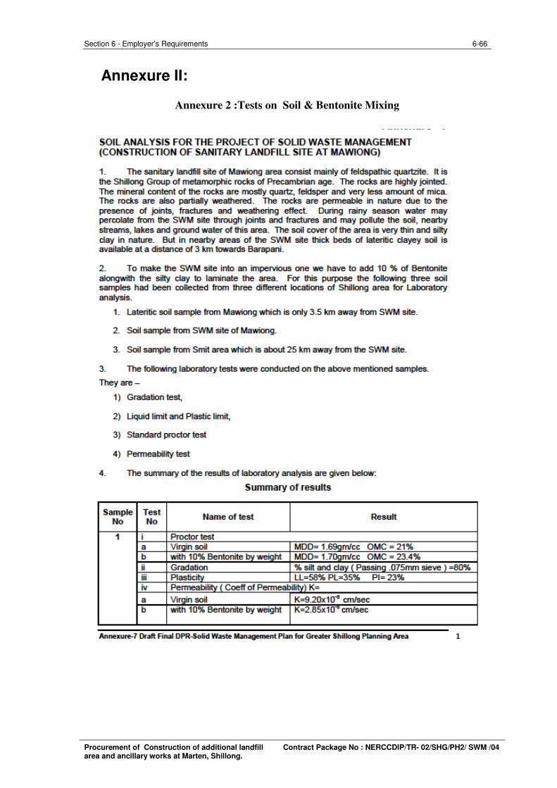
Annexure II:
Annexure 2 :Tests on Soil & Bentonite Mixing
Procurement of Construction of additional landfill Contract Package No : NERCCDIP/TR- 02/SHG/PH2/ SWM /04 area and ancillary works at Marten, Shillong.
6-67 Section 6 - Employer’s Requirements
Procurement of Construction of additional landfill Contract Package No : NERCCDIP/TR- 02/SHG/PH2/ SWM /04 area and ancillary works at Marten, Shillong.
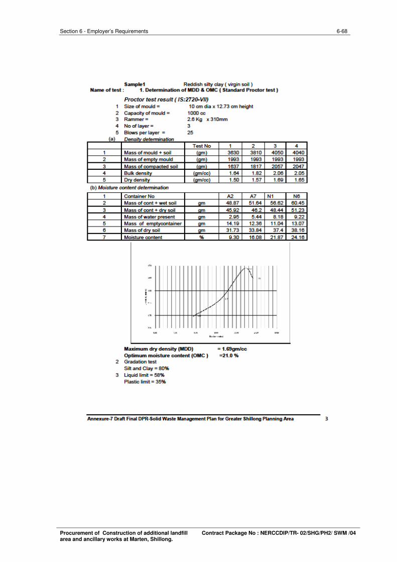
6-68 Section 6 - Employer’s Requirements
Procurement of Construction of additional landfill Contract Package No : NERCCDIP/TR- 02/SHG/PH2/ SWM /04 area and ancillary works at Marten, Shillong.
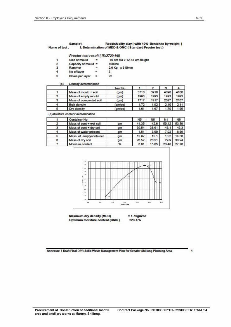
Sample1 Reddish s ilty day ( writh 10% Bentonite by weight ) Name oftest : t . Determination of MOO & OIIC ( Standard Proctor test )
Proctor test result ( 15:2721>-V/I) 1
2 3 4
5
Size of mould 10 cmdia x 12.73 cm height
Capacity of mould = 1 OOOoc Rammer 2.6 Kg x 3 1 Omm
No of layer 3
Blows per layer 25
ta \ De..,,.:#,, determination
Test No 1 1 Mass of mould + soil laml 3710 2 Mass of em.-.. mould tom) 1993 3 Mass of com~ ...... soil laml 17 17 4 Burkdensi"' trimJoc) 1.n 5 n.-., dens.n, fom/cc\ 1.61
(b )Mo«t..re content determination
1
2 3 4
5 6 7
Container No N5 Mass of cont + wet soi am 41.35 Mass of cont + """ soil am 39.54 Mass of water....._ ...... am 1.81 Mass of em ................. taine< am 12.97 Mass of.,...., soil am 26.57 Moisture col'Unt '14, 6.81
' " .. -.. .. "~ '" ,, . . , ::., ... ! ...
/ ····· .. .. ,., ~ .. .. - ~ ~ .• -___ "' ...
Max:imlW'll dry density (MOO) Optimum moisture content (OIIC )
= t .7()gmlcc =23.A %
2 3910 1993 1917 1.92 1.67
N6 42.6
38.6 1 3.99 12.1
26.5 1 15.05
'
\ 1\
-
3 4090 1993 2097 2.10 1.70
N1 50.12 43. 1 7 .02 13.2 29.9
23.48
·~
Annexure-7 Draft Final OPR--Solid Waste Management Plan for Gre.te< Shillong Planning Area
4 4 100 1993 2 107 2.11 1.65
N6 53.89 45.3 8.59
14.36 30.94 'Zl.76
4
6-69 Section 6 - Employer’s Requirements
Procurement of Construction of additional landfill Contract Package No : NERCCDIP/TR- 02/SHG/PH2/ SWM /04 area and ancillary works at Marten, Shillong.
6-70 Section 6 - Employer’s Requirements
Procurement of Construction of additional landfill Contract Package No : NERCCDIP/TR- 02/SHG/PH2/ SWM /04 area and ancillary works at Marten, Shillong.
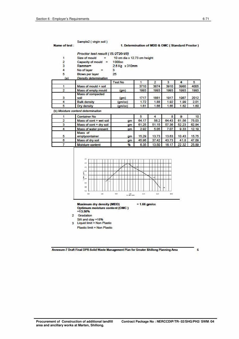
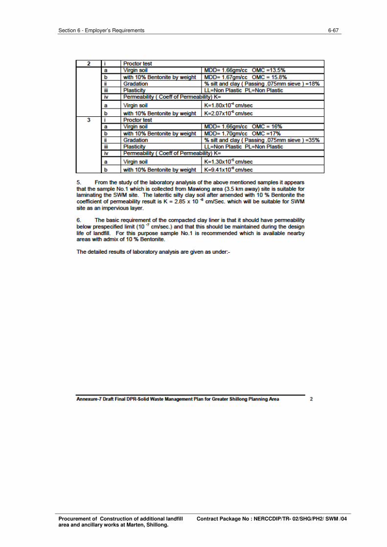
Sample2 ( YWgin soi ) Name of test : 1. Oetenni nation of MOO & OMC ( Standard Proctor)
Proctor test result ( JS; 2720· Vfl) 1 Size of mou1d ii O cm cfia x 12. 73 cm he.ight 2 Capacity of mould 1 OOOcc 3 Ramm= 2.8 Ko x 310mm 4 No of layer 3: 5 Blows per layer 25
'•' ()e,.,..,.;fu detemiination
Test No 1 Mass of mould + soil 2 Mass of ................ mould ,_ ,
Mass of~ 3 so;, ,_ , 4 Bulk doncilv la m/oc) 5 D fnm/oc\
(b) Mo;sture content determination
1 2 3 4
5 6 7
Contarler No Mass of cont + wet soil am Mass of cont + - · soil am Mass of waler ......... sent am Mass of .................. oontarier am Mass of drv soil am Moisture oontent 'lf,
.. ·- . ·-·" t .. /
f..,,. '"
I-' . .. .. - .. .. '"
Maximum dry density (110 0) Optimum moisture conte-nt (OMC ) =13...50%
2 Gc'adation Sit and clay =1 8%
3 Liquid l'i'nit = Non Plastic Plastic limit = Non Plastic
1 2 3710 3874 1993 1993
17 17 1881 1.72 1.88 1.6 1 1.66
5 4 84.17 58.2 6 1.25 5 1.15
2.92 5.05
15.29 13.73 45.96 37.42
6.35 13.50
, . \ ~
= .. = 1.66gm/cc
3 4 3910 3980 1993 1993
1917 1987 1.92 1.99 1.65 1.6.2
8 9 84.43 6 1.56 57.:la 52.23 7.07 9 .33
13.63 10 .43 43.73 4 1.8 16.17 22.32
• -
Annexure-7 Draft Final OPR--Solid Waste Management Plan for GreatH Shillong Planning Area
5 4005 1993
2012 2.0 1 1.60
10 75.03 62.84 12.19
15.75 47.09
25.89
6
6-71 Section 6 - Employer’s Requirements
Procurement of Construction of additional landfill Contract Package No : NERCCDIP/TR- 02/SHG/PH2/ SWM /04 area and ancillary works at Marten, Shillong.
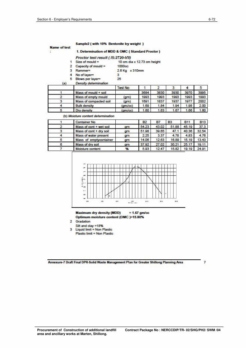
Sample2 ( with 10% Bento nite by weight ) Name· of test
1 2 3 4
5
1 2 3 4 5 6 7
la \
1. Determination of 1100 & OMC ( Standard Proctor )
Proctor test result ( JS:2720· VII) 1 Size of mould = 1 O cm1 d.ia x 12. 73 cm hei"1t 2 Capacity of mould = 1 OOOoc 3 Rammer= 2.6 Kg x310mm 4 No of layer= 3 5 Blows per layer= 25
Dend.i determination
Test t«> 1 2 Mass of mould + soil 3684 3830 Mass of e-......._, mould lo m \ 1993 1QQ3 Mass of ....-.nvc,,cted soil ·-· 1691 1837 Bolk de-..... •- •eel 1.69 1.84 Orv de,_..,_, •- •eel 1.60 1.63
(b) Moisture content dete,minab·on
Contarler No 82 Mass of cont + wet soil 54.23 Mass of cont + .-. soil - 5 1.98 Mass of waier ......,.seni - 2.25 Mass of em ............ ntainer - 14.06 Mass of drv soil - 37.92 Moisture content 'l6 5.93
·-.. ·-.. • I I'\ ; ,,,
' . ! " . ··~ ) / ... .• , .. - " .. " =
Maximum dry density (1100) = 1.67 gmlcc Optimum moisture content (OMC )=15.80%
2 Gtadation Sit and clay =18'6
3 Liquid fmit = Non Plastic Plastic limit = Non Plastic
87 43.02 39.65 3.37
12.63 27.02 12.47
~
' ..
3 3930 1QQ3 1937 1.94 1.67
83 51.88 47.1 4.78
16.89 30.2·1 15.82
. ..
Annexu:re-7 Draft Final OPR--Solid Waste Management Plan for GreatH Shillong Planning Area
4 5 3970 3gg5 1993 1QQ3 19n 2002 1.98 2.00 1.66 1.60
811 8 13 45.19 37.3 40.36 32.54 4 .83 4.76
15.19 13.43 25.17 19. 11 19.19 24.9 1
7
6-72 Section 6 - Employer’s Requirements
Procurement of Construction of additional landfill Contract Package No : NERCCDIP/TR- 02/SHG/PH2/ SWM /04 area and ancillary works at Marten, Shillong.
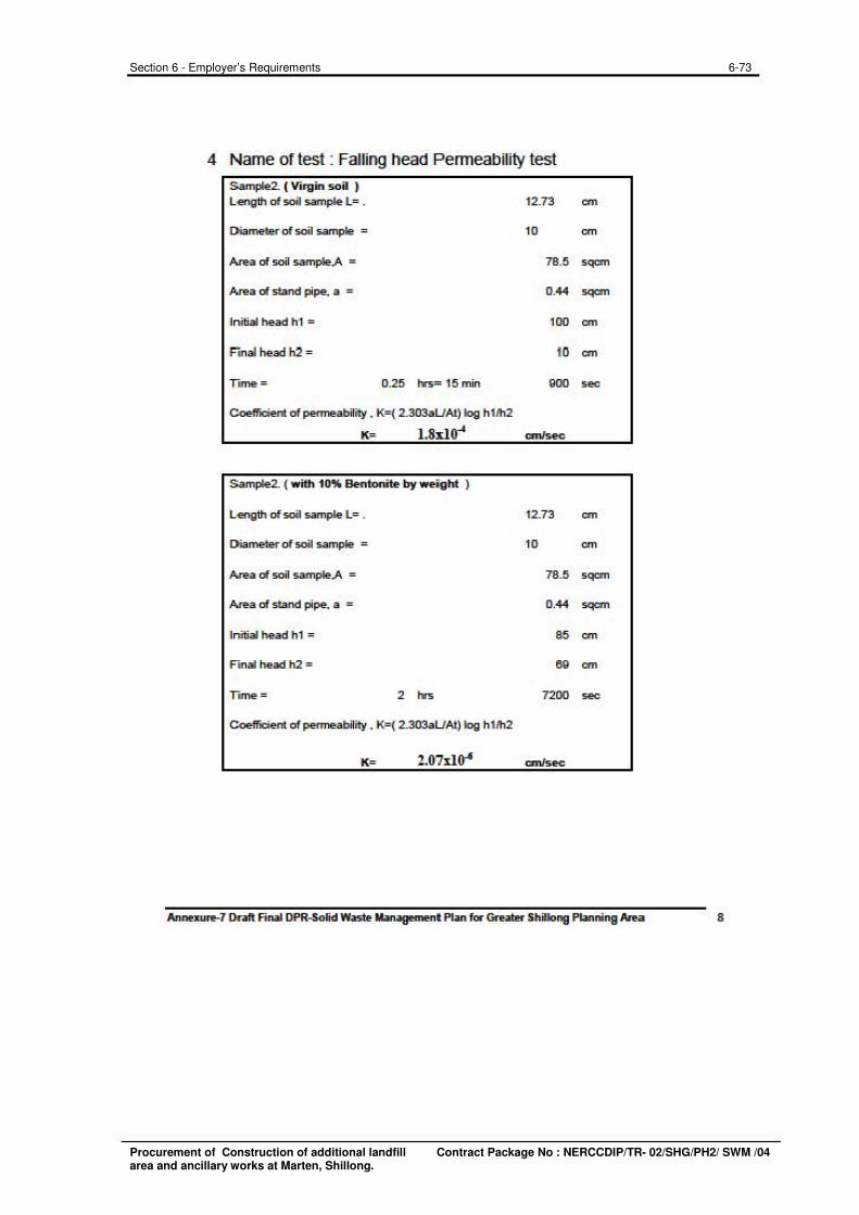
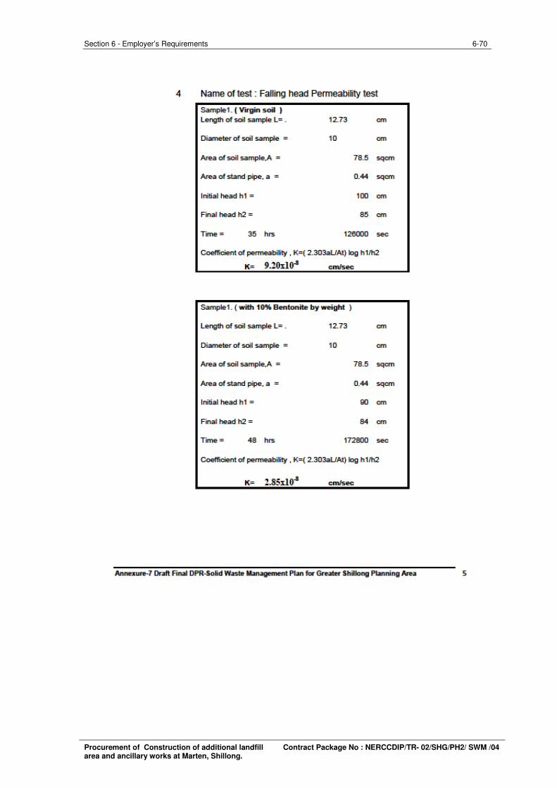
4 Name of test : Falling head Penneability test
Sample2. ( Virgin soil ) L,ength of soil sample L= .
Diameter of soil sample =
Area of soil sample.A =
Area of stand pipe. a =
Initial head h1 =
F" mal head h2 =
Tune = 0.25 IYs= 15 min
Coefficient of permeability . K=( 2.303aUAt) log h1"12
12.73
10
78.5
0.44
100
10
goo
K= 1.8,tlO-' an/sec
Sample2. ( with 10% Bentonite by we,i:ght )
L,ength of soil sample L= . 12.73
Diameter of soil sample = 10
Area of soil sample.A = 78.5
Area of stand pipe. a = 0.44
Initial head h1 = 85
F mal head h2 = 69
Tune = 2 In 7200
Coefficient of permeability . K=( 2.303aUAt) log h1"12
K= 2.07:tlO-' cm/sec
an
cm
sqcm
sqcm
an
an
sec
an
cm
sqcm
sqcm
an
an
sec
Annexure-7 Draft Final OPR--Solid Waste Management Plan for Greatef' Shillong Planning Area 8
6-73 Section 6 - Employer’s Requirements
Procurement of Construction of additional landfill Contract Package No : NERCCDIP/TR- 02/SHG/PH2/ SWM /04 area and ancillary works at Marten, Shillong.
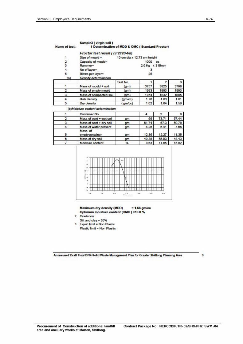
Sample3 ( virgin soil ) Name of test : 1 Determination of 1100 & OMC ( Standard Proctor)
Proctor test result I /S:2720-VIIJ 1 Size of mould = 10 cm dia x 12.73 cm ~ht 2 Capacity of mould= 1000 cc 3 Rammer- 2.6 Kg x 3 10mm 4 No of layer- 3
5 Blows per layer- 25 ta \ Den~ detennjnation
Test No 1 1 Mass of mould + soil om '.,157
2 Mass of emn"' mcdd m 1993
3 Mass of com~c:ied soil nm 1764 4 Bc.Jk de .... ;+.• {omfoc\ 1.76 5 I lrU dencitv t n m/cc) 1.62
(b)Moisture content determination
1 2 3 4
5 6 7
Contanef" No 4 Mass of cont + wet soil n m 66 Mass of co" + dn, soil om 6 1.74 Mass of wate< ........ sent o m 4.26 Mass of em-... container n m 12.36 Mass of dn, soil om 49.38 Moisture content % 8.63
. .. ' . I . ; ., ~ 4
' . ' " . . . . - .. - ..• - =
Maximum dry density (1100) = 1.66 gm/cc Optimum moisture content (OMC) =16.0 %
2 Gradation Silt and d ay = 35%
3 Liquid limit = Non Plastic Plastic limit = Non Plastic
2 3825 1993 1832 1.83 1.64
2 73.7 1 67.3 6 .4 1
12.27 55.03 11.65
'"
3 3798 1993 1805 1.8 1 1.56
8 6H4 59.78
7.66
11.35 48.43 15.82
Annexure-7 Draft Final OPR--Solid Waste Management Plan for GreatH Shillong Planning Area 9
6-74 Section 6 - Employer’s Requirements
Procurement of Construction of additional landfill Contract Package No : NERCCDIP/TR- 02/SHG/PH2/ SWM /04 area and ancillary works at Marten, Shillong.
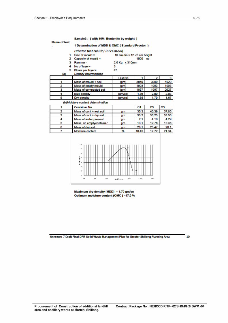
6-75 Section 6 - Employer’s Requirements
Procurement of Construction of additional landfill Contract Package No : NERCCDIP/TR- 02/SHG/PH2/ SWM /04 area and ancillary works at Marten, Shillong.
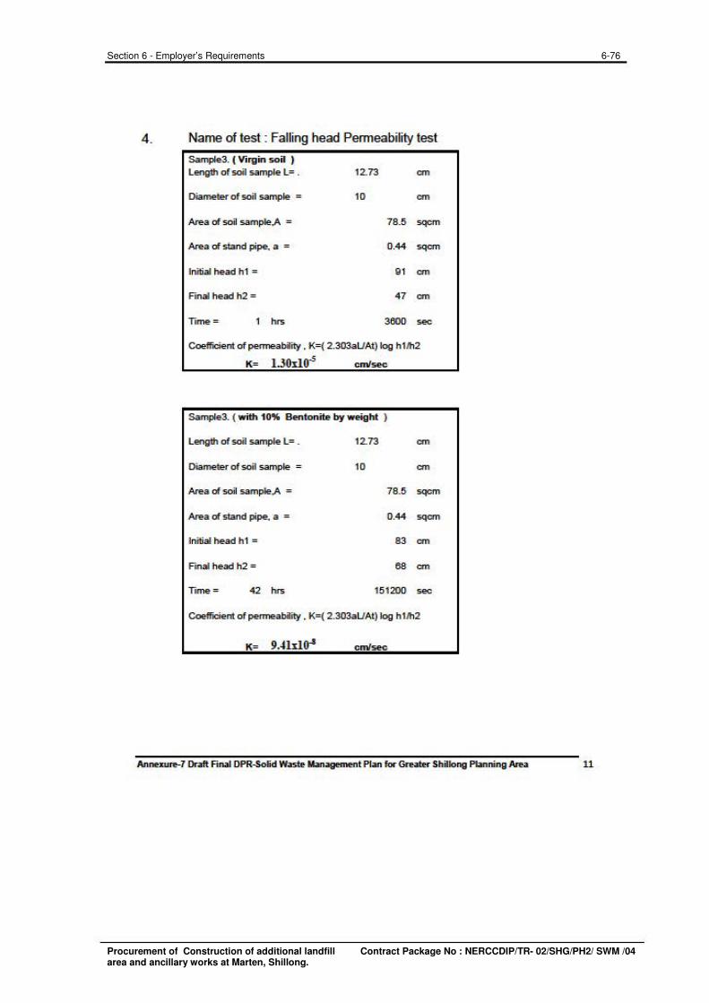
4. Name of test : Falling head Permeability test
Sample3. ( Virgin soi l ) Length of soil sample L= . 12.73 an
Diameter of soil sample = 10 an
Area of soil sample A = 78.5 sqcm
Area of stand pipe. a = 0.44 sqcm
Initial head h1 = 9 1 an
Fmat head h2 = 47 an
Trrne = Im 3600 sec
Coefficient of permeability . K=( 2.303aUAt) log h11h2
K= l .30d0.; cmlsec
Sample3. ( with 10% Bentonite by weight )
Length of soil sample L= . 12.73 an
Diameter of soil sample = 10 an
Area of soil sample A = 78.5 sqcm
Area of stand pipe. a = 0.44 sqcm
Initial head h1 = 83 an
Fmal head h2 = 68 an
Trrne = 42 Im 151200 sec
Coefficient of permeability . K=( 2.303aUAt) log h1/h2
K= 9.41d~ cmlsec
Annexure-7 Draft Final OPR--Solid Waste Management Plan for GreatH Shillong Planning Area 11
6-76 Section 6 - Employer’s Requirements
Procurement of Construction of additional landfill Contract Package No : NERCCDIP/TR- 02/SHG/PH2/ SWM /04 area and ancillary works at Marten, Shillong.
6-77 Section 6 - Employer’s Requirements
Procurement of Construction of additional landfill Contract Package No : NERCCDIP/TR- 02/SHG/PH2/ SWM /04 area and ancillary works at Marten, Shillong.