Particle size measurement of standard reference particle ...

Informal document No. 5 (44th GRPE, 10-14 June 2002, agenda item 2.)
Particle Measurement Programme (PMP).
Phase I Report.
(Transmitted by the Expert from the United Kingdom)
1
1. Introduction 1.1 Background
The Environment Council of the European Union, in its conclusions on the second Auto-Oil Programme, indicated its ongoing concern over the emissions of particles from road transport. In particular, it commented on the need for a new measuring procedure for nano-particles that would be applicable to both light and heavy-duty vehicles, and that would provide the basis for future standards aimed at a significant reduction in the emissions of particulate matter. Separately, an informal group from the UNECE Group of Experts on Pollution and Energy (GRPE) had, since 1998, been meeting on a bi-annual basis to exchange information concerning the study of vehicle emitted particulate matter. In May 2000 this group informed GRPE that they recognised that the regulated particulate limit values were approaching the limit of capability of traditional measuring techniques and instrumentation. The informal group had also recognised that emerging health concerns indicated that further measures to control particulate emissions may be required. The group advised GRPE that they considered that there would be a benefit in addressing the measurement question. The governments of France, Germany, the Netherlands, Sweden, and the United Kingdom submitted a proposal to the European Commission’s Motor Vehicle Emission Group requesting co-ordinated research on measurement methodologies and suggested that this programme be undertaken under the auspices of the UNECE to enable the widest possible contribution. This proposal was subsequently put to the 41st session of the GRPE with a request that the informal particulates group be given a formal mandate to develop a new particulate measurement methodology for application as a world harmonised standard.
1.2 The Particle Measurement Programme At its 41st session the GRPE mandated the informal group to respond to the joint proposal and agreed the terms of reference, namely:
•
To develop type approval test protocols, with instrumentation, to assess and control nano-particle emissions from (a) light-duty vehicles and from (b) heavy-duty engines within the range of 10 to 500nm (the exact range to be confirmed based on guidance of medical experts with respect to health effects).
•
Based on current research, it is anticipated that for best repeatability and reproducibility, the tests should be based on transient cycles. The cycles selected for this purpose should, if possible, conform to current regulated test cycles, i.e. European Light-duty and Heavy-duty (ETC) cycles, US Federal test cycles and also the World Heavy-duty Drive Cycle (WHDC).
•
The protocol should focus only on the accurate assessment of carbonaceous particles within the measurement range indicated.
• The group are also required to provide an assessment of current and advanced particulate control technology, as measured on the new protocol, to facilitate the development of new regulations aimed at further reductions in nano-particle emissions.
• The Group is requested to deliver their final report to GRPE in January 2003.
2
2. Health Effects When PMP was initiated it was acknowledged that, whilst the Council of Ministers of the EU had specifically requested that a measuring procedure for nano-particles be developed, there was a need to continue to monitor emerging knowledge with respect to health effects. The governments of Switzerland and the United Kingdom have both commissioned studies that address this issue, which are briefly summarised below. The Swiss report1 focuses on the occupational exposure to diesel exhaust, and discusses its role in giving rise to tumours, respiratory and cardiac symptoms and increased mortality. It highlights the role of ultrafine solid diesel particles (those smaller than 100 nm) and discusses possible reasons why these particles are particularly important. The toxicity probably increases with larger specific surface (i.e. surface area/unit mass) of the particles and dwell time in the organism. The report concludes that the current control on particulate mass is unsatisfactory from a toxicological perspective and should be supplemented or substituted by a new metric. The UK study2 aimed at providing a ‘watching brief’ over developments in knowledge of the health effects of fine particulate matter, during Phase 1. In general epidemiological studies have related mass-based particle metrics (PM10, PM2.5) to health outcomes. Recent re-analyses of existing mass-based data support a causal association between particles and acute mortality and morbidity. The UK Committee on the Medical Effects of Air Pollutants has concluded that it is more likely than not that there is a causal relationship between airborne particles and long-term health effects and that the magnitude of this effect may be up to ten times more significant that that of the short-term effects. Currently there is insufficient toxicological evidence to identify the key metric but some general conclusions can be drawn. Particle mass will continue to be an important metric due to the existing associations between PM and health effects; current hypotheses suggest the importance of ultrafine particles and metals for acute inflammatory effects, and elemental carbon (EC) has been identified as having long-term effects on health (lung cancer) and occupational exposure controls already exist. A number of studies have demonstrated that toxicity is consistent with the available surface area, but that different materials have different relative toxicities.
3. Research Group Meetings 3.1 Introduction
Responding to comments at the 41st session of the GRPE, a PMP Research Group was formed to assist in the development of the programme. The aim of the meetings was to provide a forum for interested parties to contribute their knowledge to the programme and to give those engaged in specific projects an opportunity to exchange views on their research. Consensus was desirable but not essential to the success of these meetings. Three GRPE Ad Hoc PMP Researcher Group meetings have been held during Phase 1 of the programme. Representatives of the following governments and stakeholders participated in one or more meetings:
1 Health Effects, Measurement and Filtration of Solid Particles Emitted form Diesel Engines, A Literature Study, Swiss contribution to the GRPE PMP Particle Measurement Programme, Prepared for the Federal Office of Environment, Forests and Landscapes ad the Swiss Federal Roads Authority, Report PMP-CH1 April 2001. 2 Particle Measurement Programme (PMP) Final Report of Phase 1 of Module 1: Literature Review, John McAughey, AEAT, March 2002

3
� Governments: o France, Germany, Italy, Japan, the Netherlands, Sweden,
Switzerland, United Kingdom � European Commission � Trade organisations:
o AECC, CLEPA, CONCAWE, OICA, � Research organisations /PMP contractors:
o AEA Technology, AVL, EMPA, ESYTEC Gmbh; FhG Institute of Toxicological and Aerosol Research; Matter Engineering, Peter Brett Associates, Ricardo, RWTUV, Technical University of Munich, TTM, Stockholm University, University of Windisch
� Instrument manufacturers: o Cambustion, Dekati and Horiba
3.2. 1st Research Group Meeting: London 31st July/1stAugust 2001 At this first meeting a number of participants gave presentations describing their work on PMP and related projects. These presentations indicated a broad consensus within the group that PMP should focus on solid accumulation mode particles, as nucleation mode particles are too unpredictable. Ideally the minimum time resolution of the instruments should be 1Hz, they should be capable of measuring emissions from both spark ignition and compression ignition engines/vehicles and at emission levels at or below those from three way catalyst equipped petrol cars and DPF equipped diesel vehicles.
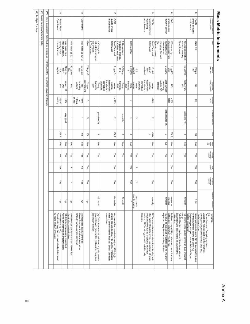
3.3. 2nd Research Group Meeting: Essen 29th/30th November 2001 The second meeting confirmed PMP’s objective to measure ‘solid particles’. It was acknowledged that this is an imprecise term, and that a final definition will be determined by the chosen measurement system(s). Most of the meeting was devoted to the development of two matrices to evaluate the potential of available instruments and sampling/conditioning systems for regulatory purposes. It was recognised that not all instruments are compatible with all sampling/conditioning systems. Thirteen instruments and 8 sampling/conditioning systems were included in these matrices, a simplified version of which is included in Annex A). It was agreed that it would be preferable to select candidate systems for Phase II that have a high degree of compatibility with the current regulatory procedures.
3.4. 3rd Researcher Group Meeting: London 18th/19th March 2002 The final researchers meeting in Phase 1 focused on assessing contributions to Phase II of the programme and establishing common ground for testing programmes. A number of ‘core’ instruments for possible inclusion in Phase II were discussed, together with the fuels and lubricants, test cycles, assessment of thermodenuders, raw and dilute sampling, and vehicle conditioning. The importance of calibration procedures was acknowledged and participants were encouraged to seek practical solutions. There was debate on whether there is a good relationship between mass and number emissions at the low emission levels expected in the future, and whether a mass based approach for both heavy and light duty applications is appropriate. Most contributors to the programme are intending to include a mass measurement technique in their Phase II work. It was agreed that an enhanced gravimetric method,

4
incorporating appropriate elements of the US 2007 and the ISO/FDIS 16183 methodologies should be used. Minutes of each of the Researchers’ Meetings are attached as Annex D).
4. Results and Recommendations of Phase 1 4.1. Introduction
Candidate systems must be accurate, repeatable/reproducible, traceable, robust and relatively inexpensive. Ideally they should also be compatible with current regulatory test procedures as the measurement of the gaseous emission, and possibly the particulate gravimetric mass measurements, will continue to be required. The Swiss and UK governments were the major contributors to Phase 1. Their contributions were built on previous work commissioned by both governments.
4.2. Heavy duty engine testing 4.2.1. UK Contribution The heavy-duty programme investigated five instruments:
•
Quartz Crystal Microbalance (QCM),
• Condensation Particle Counter (CPC),
•
Scanning Mobility Particle Sizer (SMPS),
•
Tapered Element Oscillating Microbalance (TEOM),
• Differential Mobility Analyser (DMA). In addition, the regulated gravimetric filter method was used to measure particulate mass. The programme also investigated the effects of three sample-conditioning systems (SCS):
• dilute exhaust sampling according to current regulatory procedures,
•
raw exhaust sampling
• a thermodenuder. The key conclusions from this research are:
•
Relationships between the filter mass measurements and SMPS, CPC and QCM exist when the CVS sampling system is used. The relationships when using raw exhaust sampling were poorer.
• A comparison of transient cycles with steady state operations revealed enhanced repeatability from the transient operations.
•
Below Euro IV emissions levels (post DPF) on the European Transient Cycle the CPC provided the most repeatable measurements. At these emission levels the QCM was more repeatable than the filter mass method, but no instrument showed a coefficient of variance (COV) better than 12%.
This research recommended two candidate systems for Phase II. These are (i) the CPC with thermodenuder and secondary dilution via the sample conditioning system and (ii) the QCM with the same sample conditioning system. The research also recommends that these candidate systems compliment rather than replace the mass metric since this programme has demonstrated that the gravimetric filter method can readily achieve COVs of 5% at emission levels better than Euro III and COVs of <20% at approximately one quarter of Euro IV emission levels.
5
In addition, the research observed that the DMA is currently undergoing rapid development and may in the medium term prove to be a valuable tool for engine development. The US EPA is currently considering the use of TEOM as a supplementary method for the existing filter method. Therefore it might be useful to include these instruments in Phase II.
4.3. Light duty vehicle testing 4.3.1. Swiss Contribution The Swiss government’s contribution to Phase 1 focused on the testing of NanoMet. This instrument was developed in earlier Swiss research programmes, and comprises a photoelectric aerosol sensor (PAS), a diffusion charger (DC) and a mini diluter. It measures the total active surface and the total soot surface with a time resolution of about 0.5 second. Emissions from three modern diesel cars, one with a DPF and another with a DPF/bypass retrofitted at the tailpipe to enable different levels of emission to be generated, were measured using NanoMet, SMPS and opacimetry. NanoMet was shown to have good repeatability and sensitivity and the results correlated well with those measured using SMPS under both steady and transient operating conditions. When assessing low emitting vehicles, the NanoMet was seen to be more sensitive than the gravimetric or opacimeter methods. Use of a diffusion battery enables on-line particle size distribution scanning during transient operation. Calibration of the instruments was undertaken using the Combustion Aerosol Standard (CAST) system, which generates combustion aerosol with a high degree of stability and reproducibility.
4.3.2. UK Contribution The UK light-duty research programme consisted of three components. Firstly the candidate instruments were tested in an aerosol laboratory, secondly the instruments/sampling systems were tested on one diesel vehicle, and thirdly an assessment of candidate instrument and sampling concepts was undertaken using a further three vehicles (diesel, diesel with DPF and petrol cars). In addition to the instruments evaluated in the heavy-duty programme a light scattering device was tested. Four sampling systems were investigated: CVS plus a dilution tunnel, modified CVS (dilution air added at the tailpipe), thermodenuder, and raw exhaust sampling. This research recommended the CPC with CVS (possibly modified) and an in-line thermodenuder as a candidate system for further evaluation in Phase II. The research suggests that such as system would give good reproducibility and, because its very low limit of detection, would be suitable for low emission vehicles. CPCs are robust, easy to operate and maintain, and are relatively inexpensive. However, they are susceptible to being swamped by large numbers of nucleation mode particles, and therefore require a sampling system that eliminates these particles. The DMA would offer more complete information, including number concentration, size distribution and potentially active surface area. Repeatability of the DMA is good but the model tested had a relatively high limit of detection. However, there has recently been rapid development of this technique and this shortcoming may have been overcome in more recent versions. The high limit of detection of the current regulatory filter method rules it out for low emission light-duty vehicles. It could however be used in collaboration with another metric (e.g. number) to check that mass emissions do not rise substantially whilst the other metric is reduced.

6
5. Phase II Following the 3rd meeting of the Research Group the sponsors of the individual Phase II programmes met to discuss the next steps. Those present included representatives of the governments of France, Germany, Italy, Sweden, Switzerland and the United Kingdom. Switzerland and the UK, which have been most active with their research in Phase 1, were invited to prepare a joint paper on methodologies for light-duty and heavy-duty testing during Phase II. The resulting papers have been circulated to all members of the Research Group for comment. The test methodology papers define particulate as ‘all materials collected by the conventional filter method’, and particle as ‘exhaust aerosol: solids, liquids and water as measured by the candidate system under evaluation’. The methodologies are based on existing legislated (Directive 1999/96/EC3) and draft procedures (US 20074 and, where appropriate, ISO/DIS 161835) and include an approach for the evaluation of measurement variability of test data taken at a single laboratory. The heavy-duty methodology is specifically for transient testing but may also be applicable to steady-state test cycles, and with modifications could be applicable to non-road applications. Ideally the engines/vehicles tested will include:
•
It is recognised that OEMs may not be able to offer Euro IV level technology in the time-scale of the programme. As an alternative therefore - Euro III diesel vehicles/engines equipped with a diesel particulate filter (DPF) and meeting the Euro IV particulate emission standard.
•
Euro III/IV petrol vehicles, including at least one direct injection spark ignition vehicle
It is anticipated that gaseous emissions will be measured at the same time as particulate/particle emissions, using existing regulatory techniques. The lubricating oil shall meet the standard specified by the engine manufacturer. If there is sufficient scope then a lubricant with a sulphur content below 0.4% shall be used. The fuels should conform to EU Directive 98/70/EC (2005)6 with a maximum sulphur content of 10 ppm.
6. Conclusions Phase I of PMP is now complete. The active contribution of all partners in the Research Group enabled those who are sponsoring research contributions to Phase II to focus on the key issues. Test methodologies for light-duty and heavy-duty vehicles/engines have been developed (annexes B) and C) respectively) and these take account of both the current systems available for particle number count and the most advanced procedures for particulate mass assessment. Timing of the
3 Directive 1999/96/EC of the European Parliament and of the Council of 13th December 1999 on the approximation of laws of the member states relating to measures to be taken against the emission of gaseous and particulate pollution from compression ignition engines for use in vehicles, and the emissions of gaseous pollutants form positive ignition engines fuelled with natural gas or liquefied petroleum gas for use in vehicles, and amending Council Directive 88/77/EEC 4 Code of Federal Regulations Title 40 Part 86 Subpart N – Emissions Regulations for New Otto-cycle and Diesel Heavy-Duty Engines: Gaseous and Particulate Exhaust Test Procedures (Revised July 1 2001) 5 ISO/DIS 16183 Heavy-Duty Engines – Measurements of gaseous emissions form raw exhaust gas and pf particulate emissions using partial flow dilution systems under transient test conditions. 6 Directive 98/70/EC of the European Parliament and of the Council of 13 October 1998 relating to the quality of petrol and diesel fuels, and amending Council Directive 93/12/EEC
7
programme has meant that certain promising systems for particle measurement may not be fully assessed at this time, nonetheless, this programme does not dismiss the potential of these systems for future use. Germany, France, Sweden, Switzerland and the United Kingdom have agreed to contribute to the Phase II. France is undertaking a round-robin that, whilst distinct from the PMP methodology, is nevertheless complimentary. Sweden’s contribution will also consider the chemical composition of particles. Due to the timing of the individual programmes the test methodologies developed during Phase I may not be followed precisely, however, all parties have agreed to adopt as much of the relevant specification as is practicable.
7. Annexes A) Matrices for instruments and sampling systems (shorter versions). B) Test methodology for light-duty vehicles. C) Test methodology of heavy-duty engines. D) Minutes of Researchers’ Workshops.

Annex A
i
Multiple M
etric Instruments.
Instrum
ent suitable for transient testing.
Metric.
Practical low
er limit.
Interference yes/no? - Specify.
Repeatability. (1)
Calibration - ease. (2)
Price. Applicability
for T/A.
Ambient
compatibility
yes/no?
I&M
yes/no? In-service
compliance
yes/no?
Calibration - frequency?
Rem
arks. e.g. D
ependence on Sampling system
. C
apability with respect to other m
etrics - chem
ical composition/surface area etc.
Limitations of use.
size: mobility
diameter (aggl.) +
number
distribution + active surface
50 µm
2/cm3
No < 3%
STD
1
50k € Yes
Yes Yes
Yes w
eeks to m
onths Assum
es monom
odal or bimodal lognorm
al distribution; sam
e inform
ation as SMPS, but on-line size resolution
< SMPS am
bient com
patibility: urban air concentrations; calibration: sam
e as DC
S
4
EDB
electrical diffusion battery
1)Diffussion
charging efficiency, diffusion coefficient, current 2)
~4 size
bins; num
ber
1E3-1E4 #/cm
3 nucleation particles
not possible (IV)
3 No
No
1/week
(III) measures accum
ulation mode only up to
200 nm.
(IV) no number standard available. Frequent
cleaning neccessary.
Requires
secondary dilution.
EC m
ass concentration, EC
surface area (=prim
ary particle size)
currently: som
e 10µg/m
³, theoreti
cally m
uch low
er
No 1-2%
@
EU
RO
3-level
2 Prototype: about 150.00 €
Yes Yes
Yes Yes
n/a N
o interferences, regardless of sampling
conditions applicable also as a developm
ent tool no dilution required exhaust flow
determination required, if
integrated values are favoured
7
LII Laser Induced Incandescence
1) light absorption and incandescence 2)
EC
mass
and surface
20 µg/m
3 No
possible (VIII)
1 Yes
No
1/month
(VIII) Calibration can be achieved e.g. via soot
generator and gravimetric or coulom
etric calibration
12 [D
EKATI]
1)diffusion charging efficiency, aerodyn./m
obility behavior, current 2) 7 size bins; num
ber, particle density (XI), m
ass concentration
200 #/cc, 1 µg/m
3 nucleation particles
possible(X)
3 Yes
Yes
every 2 yrs
(X) Calibration can be achieved e.g.via aerosol
generator and gravimetric calibration. R
equires secondary dilution. (XI)D
ensity for unimodal size distribution only
(sample conditioning)
NanoM
et = EDB
+ D
C + PAS +
MD
19 heated
mobility- diam
eter num
ber-distribution. active surface EC
-mass
solid/volatile-ratio
see com
ment
s
HC
for PAS <1%
1
100k €
Yes yes
special version
yes sim
plif.
version
Yes w
eeks to month
dep.on usage For practical low
er limits refer to TTM
entries for instrum
ents # 3, #4 and #8.
(*) TIRE-LII Inform
ation provided by University of Erlangen-N
uremberg (LTT / Esytec)
(1) Based on m
anufacturers data.
(2) 1= High; 5 = Low.
Annex A
ii
Mass M
etric Instruments
Instrum
ent suitable for transient testing.
Metric.
Practical low
er limit.
Interference yes/no? - Specify.
Repeatability. (1)
Calibration - ease. (2)
Price. Applicability
for T/A.
Ambient
compatibility
yes/no?
I&M
yes/no? In-service
compliance
yes/no?
Calibration - frequency?
Rem
arks. e.g. D
ependence on Sampling system
. C
apability with respect to other m
etrics - chem
ical composition/surface area etc.
Limitations of use.
Mass EC
<10 µg
m-3
No
(b) 1
(b) Yes
Yes Yes
Yes ? (b)
(a) current version up to 52° C, perspective also
for measurem
ent in raw gas (190° C
) (b) prototype, not yet com
mercial avilable, no
reliable information
5
PASS photo acoustic soot sensor
1) Light absorption; acoustic sensing 2) soot m
ass
40 µg/m3
NO
2, H2O
(V)
possible (VI)
3 Yes
Yes
1/m
onth (V) interference under control in dual channel setup (VI) C
alibration can be achieved e.g. via soot generator and gravim
etric or coulometric
calibration
EC m
ass by photoelectric yield
1 µg EC
/m3
HC
< 1%
STD
1
20k € Yes
Yes Yes
Yes w
eeks to m
onths Am
bient compatibility: urban air concentrations;
calibration: with C
AST 15-20 min
8
PAS photoelectric aerosol sensor
1)Efficiency of photo electric charging, C
urrent (fA) 2) photo current
2 µg/m3
soot surface reactivity, sulfate O
C
content;
not possible (IX)
5 N
o N
o
1/m
onth (IX) D
ue to expected interferences no linearety expected. R
equires secondary dilution.
Real-Tim
e and Total M
ass 10 - 60 µg on filter
resolved
some
volatile losses w
ith transients - correction possible
~10%
2 >50k
€ Yes
Yes
Yes annually
TEOM
mass show
s consistent relationship with
filter mass at higher levels. Breakdow
n at lower
levels may be due to problem
s with filter
method. TEO
M struggles w
ith volatile only aerosols
0.2
mg/m
3 w
ater vapour
3
Yes ?
? zero check
prior to testing
Total number
0.2mg/m
3 Tem
p, hum
idity, SO
F
? 4
3 Yes
Yes Yes
Yes ?
9 TEO
M
tapered element
oscillating m
icrobalance
1. Resonance
frequency change, 2. O
nline total mass
5-10 mg
m-3
Temp,
humidity,
SOF
possible
3 Yes
Yes
1/m
onth
Real-Tim
e and Total M
ass 2 µg/m
3 som
e volatile
losses with
transients - correction possible
ca 10%
2 16k €
Yes Yes
Yes Yes
6 months
Very sensitive microbalance (ca 150H
z/µg) - D
ilution required above 100 µg/m3. Traceable
mass [] determ
ination. Robust, Sm
all, vibration insensitive .
1. Change in
natural frequency of the crystals, 2. Total m
ass
Tem
p, hum
idity, SO
F
possible(X)
3 Yes
Yes
1/3 m
onth (X) C
alibration can be achieved e.g. via aerosol generator and gravim
etric calibration. Requires
secondary dilution.
10 Q
CM
quartz crystal m
icrobalance
Mass
2.5ug/m3
Y (gas conversion)
3 5
15k Yes
Yes Yes
Yes 1/yr
total mass @
52° C
50 µg on filter
Yes, hum
idity effects
~10%
at 100µg on filter
1 n/a
Yes Yes
No
Yes I/yr
Interferences easily controlled Allow
s for chemical characterisation
Difficulty w
hen carbon removed
total mass @
52° C
50 µg on filter
Yes
1
Yes Yes
? ?
1/yr Interferences easily controlled. Allow
s for chem
ical characterization.
11 G
ravimetric
total mass on a
filter @52deg C
50µg on
filter w
ater, HC
(XI)
<5%
very good -
Yes Yes
1/yr (XI) Interferences easily controlled Allow
s for chemical characterisation
14 Partial Flow
O
pacimeter
opacity (soot concentration)
0.3 m
g/m3
Yes 1%
of reading
1 15k €
Yes N
o Yes
Yes 1/yr
Interference by NO
2 O
pacity strongly but not exclusively determined
by black carbon emission
(**) PASS Information provided by Institute of H
ydrochemistry - Technical U
niversity Munich
(1) Based on manufacturers data.
(2) 1= High; 5 = Low
.

Annex A
iii
Size/Num
ber Instruments
Instrum
ent suitable for transient testing.
Metric.
Practical low
er limit.
Interference yes/no? - Specify.
Repeatability. (1)
Calibration - ease. (2)
Price. Applicability
for T/A.
Ambient
compatibility
yes/no?
I&M
yes/no? In-service
compliance
yes/no?
Calibration - frequency?
Rem
arks. e.g. D
ependence on Sampling system
. C
apability with respect to other m
etrics - chem
ical composition/surface area etc.
Limitations of use.
Total Num
ber C
oncentration 0
No
<5%
3 28k €
Yes Yes
Yes
6 months
CN
C w
ith integrated Diluter (SC
S) enabling both raw
and diluted aerosols to be measured.
SCS also allow
s linearity calibration to be perform
ed within the testing environm
ent. CN
C
single count and photometric m
ode.
Total number
1000#/cm
3 Yes
Nucleation Particles
10-13%
4 4
Yes Yes
Yes N
o ?
1) Particle count / light extinction 2) Particle num
ber
10000 #/cm
3 (C
VS) 10 #/cm
3 (tailpipe+synth.air)
Nucleation particles
not possible (I)
4 R
eservation
Yes
1/m
onth Very sensitive to nucleation particles. R
equires secondary dilution. (I) no num
ber standard available
1 CPC - BSU
PM
condensation particle counter
# 10^3
No
1 3
15k Yes
Yes Yes?
Yes 1/yr
Needs high dilution
Particle size/num
ber 4e4
dN/dlog
Dp/cc @
30nm
surface charging by
diffusion m
ay be chem
istry dependent
not defined
Easy for charge (fA) difficult for real aerosols.
Inlet flow needs
checking
~ 105k
€
possibly,
needs further developm
ent
Yes
yes but bulky
6 monthly,
calibrate electrom
eters by battery and
resistor
Possibly suitable for raw exhaust sampling w
ith upstream
dilution, however senistivity lim
its preclude use of v.high dilution ratios needed.
2
DMS
differential m
obility spectrom
eter
# 10^5
vibration 2
4 120k
Yes N
o N
o Yes
1/yr *range could be m
oved"
100-
200/cm3
5
Yes
? ?
zero check prior to testing
Size distribution 1000#/c
m3
Yes N
ucleation Particles
? 4
2 Yes
Yes Yes
Yes ?
1000#/c
m3
Nucleation Particles
(see com
ments)
<10%
1/year or 1/2 years
(see comm
ents)
Yes
Yes Yes
Yes 1/m
onth (see com
ments)
See separate sheet "French Rem
arks".
6 ELPI electrical low
pressure im
pactor
1)diffusion charging efficiency, aerodyn. behavior; current 2) 12 size bins; num
ber
1000 #/cm
-3 nucleation particles
not possible (VII)
2 [Yes]*
Yes Yes
1/m
onth H
as to be cleaned very often, particle bouncing, sm
all particle interference to larger stages; (VII) no num
ber standard available; effective m
ass calibration possible. * If effective m
ass based calibration is available.
Surface Area Instruments
active surface 10
µm2/cm
3 N
o < 1%
STD
1
20k € Yes
Yes Yes
Yes w
eeks to m
onths Am
bient compatibility: urban air concentrations;
calibration: with D
MA+C
PC or C
AST (15-20 m
in)
3 D
CS
diffusion charging sensor
1)Diffusion
charging efficiency
2)Fuchs Surface
10 µm
2/cm3
(tailpipe +
synth. Air)
nucleation particles
not possible (II)
5 N
o Yes
1/month
very sensitive to nucleation particles. Requires
secondary dilution. Frequent cleaning necessary to ensure constant charging. (III) no surface standard available
(1) Based on manufacturers data.
(2) 1= High; 5 = Low
.
Annex B
i
PMP PHASE II - OUTLINE LIGHT-DUTY TEST METHODOLOGY
1 INTRODUCTION This document has been prepared in response to a request from UK DTLR as part of the Particle Measurement Programme (PMP). The document’s primary purpose is to design a framework for testing in PMP Phase II. It is written as a proposed guide for testing but with a style similar to that of a legislative test procedure aimed at type approval. Associated discussion is presented within the text in Italics. Detailed aspects of the procedure have been omitted where reference to existing standards is implied.
2 SCOPE This draft test specification suggests the scope for Phase II of PMP and addresses the measurement and evaluation methods for particulate (all materials collected by the conventional filter method) and particle (exhaust aerosol; solids, liquids and water as measured by the candidate system under evaluation) exhaust emissions from light duty vehicles under transient conditions on a chassis dynamometer. It is based on existing LD procedures and also since there are many directly compatible areas, draft procedures for future HD legislation (ISO 16183 and US 2007). The standard also provides for an evaluation of measurement variability of test data taken at a single laboratory. It is anticipated that gaseous emissions would be measured at the same time as particulate or particle emissions, using established regulatory measurement techniques, although these are not specifically referred to within this document. This specification is also applicable to steady-state test cycles.
This specification is specifically concerned with an exhaust dilutionsystem comprising a full flow primary tunnel (CVS).
3 REFERENCES This specification is based on or draws from the following documents: Code of Federal Regulations Title 40 Part 86 Subpart N – Emission Regulations for New Otto-Cycle and Diesel Heavy-Duty Engines; Gaseous and Particulate Exhaust Test Procedures (Revised July 1 2001). “US2007” ISO/DIS 16183 Heavy-Duty Engines – Measurement of gaseous emissions from raw exhaust gas and of particulate emissions using partial flow dilution systems under transient test conditions. Not yet an approved document and referred to as “16183”. Euro Directives 1999/96/EC Annex III and 1998/69/EC “Euro”
Aerosol Measurements: Principles, Techniques and Applications.
Ed: Klaus Willeke and Paul A Baron 1993. Van Nostrand Reinhold
4 TEST CONDITIONS 4.1 Engine test conditions
For a test to be recognised as valid the engine intake air temperature and humidity must be controlled within limits. The limits are defined in directive 98/69/EC. Current Euro regulations shall be assumed.
There is no requirement for barometric pressure control for LD testingin Europe.

Annex B
ii
4.2 Engine Specification All diesel-fuelled vehicles tested should be equipped with Diesel Particulate Filters (DPFs). The vehicles tested shall conform to both Euro III light duty emissions requirements for gaseous emissions and Euro IV particulate emissions requirements when a DPF is fitted. It is possible that OEMs will not be in a position to provide EuroIV rated engines in the time-scale of this programme, therefore EuroIV PM levels may be achieved with a retrofit. DPFs suitable for theengines tested shall be provided after discussion with the enginemanufacturer and if appropriate AECC.
All gasoline fuelled light duty vehicles tested shall conform to either Euro III or Euro IV specifications. At least one G-DI shall be tested.
4.3 Lubricating Oil The lubricating oil shall meet the standard specified by the engine manufacturer. If there is sufficient scope, then a lubricant with a sulphur content below 0.4% (4000ppm) shall be used. A batch analysis of the lubricant to be employed will be conducted.
Mineral oils typically have a sulphur level of 0.7% to 0.9%. Syntheticoils may have sulphur levels as low as 0.3%.
4.4 Test Fuel A Diesel reference fuel of less than 10ppm sulphur fuel shall be used, this fuel will otherwise conform to Directive 98/70/EC (2005). This reference fuel shall be CEC RF-06-99 with a sulphur level of ~2ppm if a sufficient quantities from a single batch can be sourced from Haltermanns. A gasoline fuel of less than 10ppm sulphur shall be used, this fuel will otherwise conform to Directive 98/70/EC (2005). Batch analyses of the fuels to be employed will be conducted.
The availability of appropriate reference fuels, or an appropriatemarket Diesel and petrol, will be discussed with Concawe. Proposed2008 market diesel and gasolines may be the preferred options.
5 TEST PROTOCOL 5.1 Engine Test Cycles
The vehicle test schedule shall include testing of a preconditioned, temperature controlled vehicle over the cold start 98/69/EC (NEDC) cycle.
(Following preconditioning and overnight soak. Emissions measured overthe 70/220/EC dynamometer test cycle where the first 40 seconds of
engine idle where there was no emissions sampling are removed)
This test cycle shall be run in accordance with existing European standards for LD vehicles.
For Diesel vehicles, data shall be split into the two phases of the NEDC cycle; ECE (0-780s) and EUDC (781-1180s). However, for gasoline types where accumulated mass is likely to be low, for best data quality one single sample for the entire NEDC shall be acquired. Test work will also address repeat hot start transient cycles since multiple tests are required to determine repeatability within one day.
Test work may also address hot US FTP cycles and steady state,extended modes comprising single speeds drawn from the NEDC cycle.
Annex B
iii
5.2 Repeat Tests All tests shall be carried out at least 7 times. This is consistent with the minimum sample size suggested by US2007 and 16183 standards as the basis of an assessment of the equivalence of an alternative system. A comparison of systems on this basis shall then be carried out using statistically based data analysis methods. This shall include calculation of appropriate confidence intervals for all reported values. Analysis methods described in ISO5725(1994) may be used, but note that this programme will not be able to deal with any aspects of inter-laboratory or test specimen related variability.
5.3 Testing Approach 5.3.1 Evaluation of Candidate Systems Over Three Emissions Cycles
For each of three drive cycles: • At least seven tests shall be conducted contiguously in one single day • At least seven tests shall be conducted on different days • The first of any group of repeated cycles shall follow the same warm-up and order of
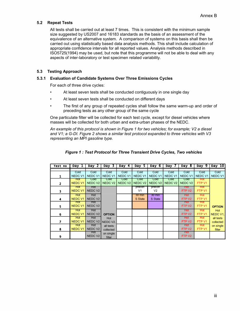
preceding tests as any other group of the same cycle One particulate filter will be collected for each test cycle, except for diesel vehicles where masses will be collected for both urban and extra-urban phases of the NEDC. An example of this protocol is shown in Figure 1 for two vehicles; for example; V2 a diesel and V1; a G-DI. Figure 2 shows a similar test protocol expanded to three vehicles with V3 representing an MPI gasoline type.
Figure 1 : Test Protocol for Three Transient Drive Cycles, Two vehicles
Test noTest noTest noTest no Day 1Day 1Day 1Day 1 Day 2Day 2Day 2Day 2 Day 3Day 3Day 3Day 3 Day 4Day 4Day 4Day 4 Day 5Day 5Day 5Day 5 Day 6Day 6Day 6Day 6 Day 7Day 7Day 7Day 7 Day 8Day 8Day 8Day 8 Day 9Day 9Day 9Day 9 Day 10Day 10Day 10Day 10
1111
ColdNEDC V1
ColdNEDC V1
ColdNEDC V1
ColdNEDC V1
ColdNEDC V1
ColdNEDC V1
ColdNEDC V1
ColdNEDC V1
ColdNEDC V1
ColdNEDC V1
2222
HotNEDC V1
ColdNEDC V2
ColdNEDC V2
ColdNEDC V2
ColdNEDC V2
ColdNEDC V2
ColdNEDC V2
ColdNEDC V2
HotFTP V1
3333
HotNEDC V1
HotNEDC V2
preconV1
preconV2
HotFTP V2
HotFTP V1
4444
HotNEDC V1
HotNEDC V2
30 minS State
30 minS State
HotFTP V2
HotFTP V1
5555
HotNEDC V1
HotNEDC V2
HotFTP V2
HotFTP V1
6666
HotNEDC V1
HotNEDC V2
HotFTP V2
HotFTP V1
7777
HotNEDC V1
HotNEDC V2
HotFTP V2
HotFTP V1
8888
HotNEDC V1
HotNEDC V2
HotFTP V2
HotFTP V1
9999
HotNEDC V2
HotFTP V2
OPTION Hot
NEDC V2, all tests collected on single
filter
OPTION Hot
NEDC V1, all tests collected on single
filter
Annex B
iv
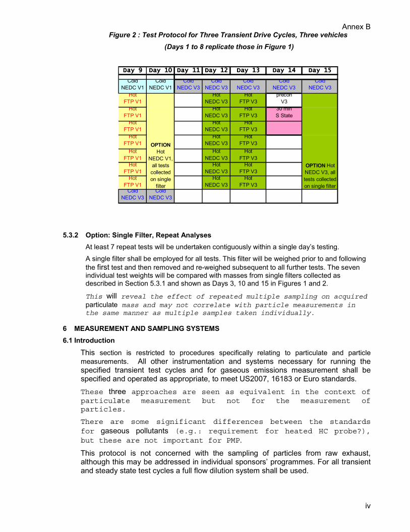
Figure 2 : Test Protocol for Three Transient Drive Cycles, Three vehicles (Days 1 to 8 replicate those in Figure 1)
Day 9Day 9Day 9Day 9 Day 10Day 10Day 10Day 10 Day 11Day 11Day 11Day 11 Day 12Day 12Day 12Day 12 Day 13Day 13Day 13Day 13 Day 14Day 14Day 14Day 14 Day 15Day 15Day 15Day 15
ColdNEDC V1
ColdNEDC V1
ColdNEDC V3
ColdNEDC V3
ColdNEDC V3
ColdNEDC V3
ColdNEDC V3
HotFTP V1
HotNEDC V3
HotFTP V3
preconV3
HotFTP V1
HotNEDC V3
HotFTP V3
30 minS State
HotFTP V1
HotNEDC V3
HotFTP V3
HotFTP V1
HotNEDC V3
HotFTP V3
HotFTP V1
HotNEDC V3
HotFTP V3
HotFTP V1
HotNEDC V3
HotFTP V3
HotFTP V1
HotNEDC V3
HotFTP V3
ColdNEDC V3
ColdNEDC V3
OPTION Hot
NEDC V1, all tests collected on single
filter
OPTION HotNEDC V3, all tests collected on single filter
5.3.2 Option: Single Filter, Repeat Analyses
At least 7 repeat tests will be undertaken contiguously within a single day’s testing. A single filter shall be employed for all tests. This filter will be weighed prior to and following the first test and then removed and re-weighed subsequent to all further tests. The seven individual test weights will be compared with masses from single filters collected as described in Section 5.3.1 and shown as Days 3, 10 and 15 in Figures 1 and 2.
This will reveal the effect of repeated multiple sampling on acquiredparticulate mass and may not correlate with particle measurements inthe same manner as multiple samples taken individually.
6 MEASUREMENT AND SAMPLING SYSTEMS 6.1 Introduction
This section is restricted to procedures specifically relating to particulate and particle measurements. All other instrumentation and systems necessary for running the specified transient test cycles and for gaseous emissions measurement shall be specified and operated as appropriate, to meet US2007, 16183 or Euro standards. These three approaches are seen as equivalent in the context ofparticulate measurement but not for the measurement ofparticles.
There are some significant differences between the standardsfor gaseous pollutants (e.g.: requirement for heated HC probe?),but these are not important for PMP.
This protocol is not concerned with the sampling of particles from raw exhaust, although this may be addressed in individual sponsors’ programmes. For all transient and steady state test cycles a full flow dilution system shall be used.
Annex B
v
The particulate measurement system shall comprise: • Sample Probe
• Primary dilution tunnel • Particle preclassifier • Particulate sampling filters • Microgram balance • Weighing chamber
For particle measurements the following systems shall also be required: • Additional dilution system(s) hereafter called tertiary (3°) dilution to distinguish from the
partial flow secondary dilution systems employed with HD primary dilution systems. • Sampling lines
• Thermodenuder • Primary Particle instrumentation (Core Instruments) • Secondary Particle instrumentation (Additional Instruments)
6.2 Primary dilution tunnel The primary dilution tunnel specification shall follow as far as possible the US2007 requirements, characterised by:
• Accurate flow measurement using a Positive Displacement Pump (PDP) with heat exchanger or Critical Flow Venturi (CFV) with either heat exchanger or flow compensation for the particulate sampling system. US2007 allows all variants of CVS system; a more rigorousspecification retaining some flexibility could be determined ifthis will lead to greater comparability between studies.
• A dilution air filtration system equipped with a HEPA filter. This should provide 98% particle removal. The reduction provided by these filters shall be briefly evaluated and quoted. This is the US2007 standard – 98% particulate removal may beachievable. HEPA filters suitable for flow regimes in excess of18m3/min are commercially available. However, commercial filtersmay permit a lower efficiency than this. This performance shall be evaluated during the programme.
• Negligible effect on engine backpressure – a static pressure drop of less than 1.25kPa. This affects engine performance, and for greatest consistency theEuro limit is proposed.
• Sized to provide turbulent flow and good mixing. (Reynolds No > 4000, >8in diameter) • Designed to cool the exhaust by dilution rather than heat transfer – of minimal thermal
capacity. If possible the tunnel should be thermally insulated. • Constructed from non-reactive, electrically conductive materials, and electrically
grounded. • Dilution air temperature and tunnel flow rate should be controlled to avoid condensation
but maintain tunnel temperature below 52°C.

Annex B
vi
6.3 Particulate Measurement System Hardware • Dilution and sample flow control systems • Sample preclassifier(s) • Filter holder assembly with bypass
The detailed specification of these systems shall be according to US2007. The following sections may add to or qualify those specifications:
6.3.1 Dilution and sample flow control systems Flow control systems shall be provided for the primary dilution airflow and the filter sample flows. The filter sample flow should be controlled to +/- 5% of the set flow. These systems shall incorporate instrumentation for the measurement of flow rates as required. The flow controllers shall be operated so as to achieve constant mass flow rates, compensating as required for changes in gas temperatures.
6.3.2 Particulate Sampling Particulate samples shall be drawn from the primary dilution system. In the primary tunnel, a thin walled, sharp edged, open-ended sampling probe will be employed for sampling. This will face directly into the direction of flow. Outside the primary dilution tunnel, a particle preclassifier shall be installed upstream of the filter holder. The preclassifier shall provide a cut-point at a particle size between 2.5µm and 10µm. This will exclude mechanically generated particulate and largeparticles which are over-sampled when sampling flow rate exceeds theflow rate through the secondary dilution tunnel. The cut-pointrange of the preclassifier enables a range of sampling flows at thefilter face to be permissible.
6.3.3 Particle Sampling In the primary tunnel, a thin walled, sharp edged, open-ended sampling probe will be employed for sampling. This will face directly into the direction of flow. The sample probe does not require a ‘chinese’ hat to exclude themechanically generated material, this is the purpose of thepreclassifier. The cut-point range of the preclassifier enables a rangeof sampling flows at the filter face to be permissible. In practice,flow rates of between 60l/min and 90l/min are permitted to staywithin the cut-point range of the preclassifier.
Current pump specifications may not be capable of these flow ratesand this may require investment of a second set of pumps and flowcontrol system.
Outside the primary dilution tunnel, a particle preclassifier shall be installed upstream of the filter holder. The preclassifier shall provide a cut-point at a particle size between 2.5µm and 10µm. This second preclassifier shall be used to provide samples for particle measurement instrumentation. Preclassifiers shall be specified in accordance with US2007.
6.4 Particulate Sampling Filters 6.4.1 Filter specification
Fluorocarbon coated glass fibre filters or fluorocarbon based membrane filters are required. All filter types shall have a 0.3µm DOP collection efficiency of at least 95% at a gas face velocity between 35 and 100 cm/s.
Pallflex type TX40H120WW-47 filters are recommended.
Annex B
vii
6.4.2 Filter size Particulate filters shall have a diameter of 46.5±0.6mm, with a stain area of 38mm minimum diameter.
Achieved by TX40H120WW-47.
6.4.3 Filter loading Filter loading shall be greater than 0.11mg and maximised within the constraints of temperature. This is a reduction of the 0.25mg specified for US 2007. Level isrelaxed since other sampling constraints may preclude the acquisition ofthis level of mass. 16183 (FDIS) quotes 0.11mg and this is adoptedhere. US EPA have demonstrated a COV of <10% at ~ 100µg on thefilter.
An objective of the programme should be to evaluate the current filtermass methods within the scope of this programme, and to determinewhat in reality this filter loading should be even if below 0.11mg.
6.4.4 Filter holder assembly A filter holder and cartridge assembly shall be used, according to US2007 specifications, and shall be temperature controlled to a maximum of 52°C. A single filter shall be used for all tests (no backup filter). 16183 and Euro standards have no specific requirements for filterholders. US2007 allows for heating of the holder, but does notrequire it.
6.4.5 Background Filters Background filters shall be collected each day prior to the commencement The variation in background masses will be compared with the overallvariation in particulate measurements. An assessment of the impactof ambient subtraction on particulate mass repeatability can then beundertaken and the validity of this procedure examined.
6.5 Microgram balance The analytical balance used to determine filter weight shall have a precision (standard deviation) of better than 2 µg for a clean filter; better than 0.25µg for a reference weight and a resolution or readability of 1µg.
This is a combination of the thresholds of US2007 and 16183 standards,excepting that a 0.1µg resolution (rather than 1µg) is required forthe balance. Specification above is currently achievable at Ricardowithout a Class 1000 clean room.
6.6 Weighing chamber The environment and procedures used for stabilisation and weighing of filters shall be controlled as far as possible in accordance with the US2007 standard. All laboratories shall specify in detail, with reference to the 2007 standards, their current facilities. The quality of the PM results and variation in reference filter weights recorded during the programme shall then be related to each test facility. These data can then be used to indicate whether the full US 2007 specification is required. US2007 sets limits for temperature and humidity, with recommendedcompliance with “Class 1000” clean room standard. A Class 1000 cleanroom also requires less than 35000 particles of >0.5µm diameter percubic metre of air. US2007 also requires the weighing chamber
Annex B
viii
temperature and humidity to be monitored at a 1Hz frequency with a 5second moving average.
6.7 Tertiary Dilution System(s) For particle sampling, additional dilution shall be provided downstream of the primary dilution system and preclassifier by tertiary (3°) dilution systems. These 3° dilution systems shall be equipped with sampling manifolds in order to provide equivalent samples simultaneously to multiple instruments. Dilution air shall be cleaned using a HEPA filter specified to achieve a minimum particle removal efficiency of 99.97%. If heated dilution is to be employed, dilution air shall be controlled to +/- 5°C of the specified temperature. Aerosol drawn into a 3° dilution system shall be as a sub-sample from the flow drawn through the preclassifier. The dilution ratio provided by a 3° dilution system shall be selected according to the instruments evaluated. For example, a dilution ratio of 1000:1 may be required for condensation nucleus counters. Further dilution ratios for other instrumentation may be provided by additional 3° dilution systems. Dilution ratios should be recorded on a second-by second basis and the parameter(s) controlling dilution ratio controlled to a tolerance of +/- 5%.
6.8 Sampling lines Sampling tubing used for sampling from the primary dilution system and to join tertiary dilution systems to particle measurement instrumentation shall, wherever possible, be straight metallic (Cu or stainless steel) conductors of <1m length. Tubing shall be electrically earthed, and if heated dilution is employed, thermally insulated.
Good sampling practice for aerosols.
6.9 Thermodenuders Sample conditioning to remove the volatile fraction of particulate present as nucleation mode particles shall be undertaken with a thermodenuder or ‘thermodesorber’ device.
6.9.1 Thermodenuder Description Thermodenuders consist of a heated inlet and desorption region where volatile materials are forced into the gaseous and vapour states, and a cooled adsorption region where these materials are retained upon activated carbon.
6.9.2 Thermodenuder Performance The thermodenuder shall have been characterised (Section 8.4) prior to inclusion within the PMP phase 2 programme. The performance of a thermodenuder at removing nucleation mode particles is determined by a number of factors; temperatures, flow rates, residence times and adsorption surface area of the activated carbon (charcoal) adsorbent. These factors combine to generate the particular particle removal characteristics of a thermodenuder and must be controlled to ensure repeatable performance. The following parameters shall be measured:
• Controlled wall temperature of Inlet to heated (desorption) region (T1) • Controlled wall temperature at outlet of heated region (T2) • Temperature at outlet of adsorption region (T3) • Flow rate through denuder (Qd)
The following constants shall be stated: • Denuder length (L) Heated Section
Annex B
ix
• Denuder diameter (D) Internal Diameter
• Surface area of activated charcoal
The following shall be calculated and reported: • Reynolds number (to ensure laminar flow) in adsorption region
• Particle penetration efficiency for 30nm to 2.5µm particles with respect to inertial and diffusional losses
6.9.3 Thermodenuder Losses Particles are lost within a thermodenuder as a consequence of diffusion, impaction and thermophoresis. Diffusion losses are likely to be significant (>1.5%) only in particle sizes below 30nm. Impaction losses reach ~2% at 1.5µm and are ~0.3% at sizes below 0.5µm. Since the purpose of the thermodenuder is to remove nucleation mode particles enabling the sole measurement of the accumulation mode, diffusional losses (<30nm) can be accepted if well controlled. Similarly, on a particle number basis, inertial losses will be insignificant and can be accepted. Perhaps the greatest contribution to losses will therefore be from thermophoresis. These losses do not have a great dependence on size and may affect the accumulation mode significantly. Total losses in the accumulation mode shall be distinguished from reductions in particle number concentration attributed to denudation. Losses shall be less than 30% in total across the size range 20nm to 700nm when measured by SMPS at the inlet and outlet of the denuder.
6.9.4 Thermodenuder Verification To demonstrate repeatable performance, on a daily basis the thermodenuder shall be operated within the specified parameters (Section 6.9.5) with a polydisperse aerosol which shows a monomodal size distribution with a peak between 50nm and 130nm as determined by an SMPS measuring the size range 20nm to 750nm.
Particle size distribution from SMPS dependent on set-up. (SAE 2001-01-2850).
Sheath flow 3lmin, sample flow 0.3l/min, up scan 120s down scan 60s.Software Version 2.4, 0.0508 impactor.
The size distributions upstream and downstream of the thermodenuder shall be characterised by SMPS. Particle losses in the region 30nm to 500nm should not be greater than 30% in any single size channel as determined by SMPS and the ratio of upstream to downstream integrated total should be within +/- 5% of the mean of all previous daily values.
6.9.5 Thermodenuder Specification The specification of the thermodenuder can then be defined thus:
• Particle losses <30% total (20nm to 750nm) and <30% in any single channel between 30nm and 500nm
• 200°C<T1>300°C; tolerance +/- 5% • T2 = T1; tolerance +/- 5% • Calculated penetration efficiency >95% for 30nm particles (diffusional losses) • Calculated penetration efficiency >95% for 500nm particles (inertial losses) • Reynolds number in adsorption region <2300

Annex B
x
Values and tolerances agreed between Ricardo and EMPA. Flow rate tobe a high as possible to minimise damping of transient events.
6.9.6 Thermodenuder Positioning
Themodenuders will be employed to condition aerosol for particle measurements. The thermodenuder will be situated outside the primary dilution tunnel. The thermodenuder shall be situated downstream of a particle preclassifier. However, if no mass based measurements are to be made downstream of the thermodenuder, the preclassifier may be omitted. A single denuder upstream of a diluter can feed multiple instrumentsbut must tolerate a high flow rate. If mass is to be measured, and ahigh dilution ratio employed downstream of the thermodenuder, asingle particle penetrating the denuder may significantly skew thedata. Therefore the use of the preclassifier is recommended tominimise the breakthrough of spurious large particles.
6.10 Correction of Particle Measurements for Ambient Concentration No correction for ambient particle number is deemed appropriate. With HEPA filtered tertiary dilution air, the contribution ofdilution air particles to measured total will be minimal. IfHEPA filtered primary dilution air is employed, ambientcontribution will be negligible.
No correction for a system blank is deemed appropriate. The determination of a system blank for particle measurements cannotbe easily undertaken; CVS tunnel particle levels during stableconditions prior to engine switch-on are unlikely to be representativeof particle contributions from the system during a thermallyvariable dynamic test.
While not subtracting a blank is not an ideal scenario, it is deemedto be better than a poorly understood arbitrary correction.
7 TEST PROCEDURE Testing will be undertaken to the appropriate regulations. For European testing this will be directives 70/220/EEC and 98/69/EC.
7.1 Test Preparation Preparation work shall be undertaken to establish appropriate vehicle condition and settings for operation of the transient cycle.
7.1.1 Vehicle Receipt and Condition Test vehicles shall show a minimum of 8000km accumulated mileage and serviced in accordance with manufacturers guidelines.
7.1.2 Dynamometer Preparation Equivalent test inertia and vehicle-on-dynamometer coast-down data supplied with the vehicles shall be matched as far as is practicable on the chassis dynamometer prior to the commencement of the test programme. Inertia and coastdown data to be supplied by the vehicle manufacturers. In the absence of this information vehicles will be tested using the default table loads documented in Regulation 70/220/EEC Annex III Appendix 2 Section 3.2.1.

Annex B
xi
7.1.3 Vehicle preconditioning All vehicles will be pre-conditioned for the cold start emissions tests in accordance with the European regulations:
• For gasoline vehicles (including GDI) this shall be one NEDC (ECE+EUDC) drive cycle followed by an overnight soak at typically 24°C+/-1.5ºC
• For diesel vehicles this shall be ECE + 3*EUDC drive cycles followed by an overnight soak at typically 24°C+/-1.5ºC
7.2 Dedicated Dilution Systems Testing of gasoline vehicles (MPI and G-DI) shall be undertaken in a primary dilution tunnel that is dedicated to non-diesel applications. A second dilution tunnel shall be employed for diesel vehicle (including with DPF) testing. These tunnels may be connected to the same CVS system. There is a risk of contaminating gasoline particles/particulateswith carbon and hydrocarbons from diesel vehicles if the samedilution tunnel is employed.
7.3 Test and Conditioning Protocols Testing shall commence first thing in the morning, prior to the testing of any non-programme vehicles. In any given dilution tunnel, vehicles shall be tested in order of ‘cleanness’ (with respect to particulate emissions). Thus on any given day, the first vehicles to be tested in a gasoline tunnel shall be MPI gasoline followed by G-DI. If non-DPF equipped diesel vehicles are to be tested these should be tested following those diesels equipped with particulate traps. Cleaner vehicles are unlikely to carry over as much particulatematerial to subsequent vehicles.
Preconditioning of a vehicle for the subsequent day’s testing shall be undertaken directly following the completion of testing on that vehicle (or conditioned in another facility), unless the vehicle is the first to be tested in either the diesel or the gasoline tunnels on the following day. In this case, the vehicle should be conditioned last thing at night. The first vehicle tested will then be exposed to a cold, stable dilutiontunnel that has been preconditioned with its own exhaust.
7.4 Sample Filter Preparation At least 1 hour before the test, two or more filters shall be placed in closed but unsealed petri dishes and placed in the weighing chamber for stabilisation. After stabilisation, but not longer than 8 hours before the test, the filters shall be weighed and the tare weight recorded. All filter weights shall be corrected for buoyancy. Sample filters shall then be installed in a sealed filter holder and stored in the weighing chamber until needed for testing. The other filters shall be retained in the weighing chamber as reference filters.
7.5 Measurement Test Cycle The test cycle shall be run in accordance with the appropriate standard. At the start of the test cycle the particulate sampling system shall be switched from by-pass to sample. All instrumentation shall be logged continuously throughout the test at least 1Hz.
7.6 After the Test At the end of the test the particulate system shall be switched back to by-pass and the filter holder removed to the weighing chamber within 1 hour of the end of the test. The sample filter shall then be removed for stabilisation period of between 1 and 60 hours before being weighed. At this time the reference filter or filters shall also be re-weighed.
Annex B
xii
Test results shall then be analysed using standard methods to calculate particulate mass emissions and cycle validation, including verification of reference filter weights. This acceptance criterion for validation of reference weights ismost stringent in US2007 which requires 10µg. 16183 presents widerscope at 10µg +5% of the filter mass. The real variability inreference filter weights between laboratories can be determined andrelated to the facility specification.
If the majority of tests would fail 16183, then this should be takenas an indication that efforts to move towards US2007 clean roomstandards are required.
8 CALIBRATION PROCEDURES 8.1 Particulate Measurement
This test specification is not overly concerned with absolute measurement uncertainty, but does aim to quantify measurement variability. For this reason, evidence shall be presented of calibration checks enveloping the test programme, which will constitute a reasonable sample (>7) for meaningful statistical analysis. These calibration checks should include the total CVS system verification (e.g.: propane CFO check), and a check of the calibration of the particulate sample air flow meters. Analysis of reference filter weighing data should also be presented.
8.2 Particle Measurements All particle measurement instrumentation shall have been subject to recent calibration within the period (annual/monthly/weekly) recommended by the manufacturer. Emphasis in this programme will be on the repeatability of the instrumentation, and testing duration is likely to be relatively short. A high degree of repeatability will therefore indicate consistency of instrument operation. Close correlation with PM (itself subject to rigorous control) willalso indicate consistency of operation.
Therefore any instrumentation showing high variability (>50% COV) shall be subject to calibration following completion of testing to establish whether variability was influenced by calibration drift. Alternatively, the instrument can be rejected as a candidate from the programme.
8.3 Tertiary Dilution Systems Tertiary dilution systems should be subject to a flow calibrations prior to commencement of the test programme. These dilution systems shall have been well characterised prior toinclusion in PMP, though it is recognised that where a particularcandidate system contains a dedicated diluter, this will beevaluated as part of that system during the programme.
8.4 Thermodenuders Thermodenuders should be characterised for losses with aerosols where particulate composition varies: • Predominantly solid • solid and volatile • Predominantly volatile • Real exhaust aerosol post-DPF

Annex B
xiii
It shall be demonstrated that the thermodenuder does not significantly affect the location of the peak in the accumulation mode (+/- 5%; >45nm) and reduces the integrated value of a dominant nucleation mode (<40nm) by at least 70%.
Annex C
i
PMP PHASE II - OUTLINE HEAVY-DUTY TEST METHODOLOGY 1 INTRODUCTION
This document has been prepared in response to a request from UK DTLR as part of the Particle Measurement Programme (PMP). The document’s primary purpose is to design a framework for testing in PMP Phase II. It is written as a proposed guide for testing but with a style similar to that of a legislative test procedure aimed at type approval. Associated discussion is presented within the text in italics. Detailed aspects of the procedure have been omitted where reference to existing standards is implied.
2 SCOPE This draft test specification suggests the scope for Phase II of PMP and addresses the measurement and evaluation methods for particulate (all materials collected by the conventional filter method) and particle (exhaust aerosol; solids, liquids and water as measured by the candidate system under evaluation) exhaust emissions from heavy-duty engines under transient conditions on a test bed. It is based on existing legislated procedures and draft documentation. The document also provides scope for an evaluation of measurement variability of test data taken at a single laboratory. It is anticipated that gaseous emissions would be measured at the same time as particulate or particle emissions, using established regulatory measurement techniques, although these are not specifically referred to within this document. This specification is also applicable to steady-state test cycles and with certain modifications may also be applied to passenger car engines and to engines used in non-road applications. This specification is specifically concerned with an exhaustdilution system comprising a full flow primary tunnel (CVS) combinedwith secondary dilution of a fraction of the CVS flow. This isconsidered the best approach for reliability of particle andparticulate measurements, and is in line with the US2007 standard.ISO16183/DIS covers the application of partial flow dilution systemsto transient engine testing. The partial flow approach is notpreferred because of the relatively high uncertainty of dilutionratio measurement, particularly when high dilution ratios arerequired. Partial flow sampling is not allowed for either US FTP orEU ETC transient testing, but both standards allow for alternativesystems to be used if their equivalence can be demonstrated.
Ricardo has had very limited access to the ISO/FDIS 16183 and wouldappreciate correction where DIS and FDIS differ.
While the general principle of the ISO16183 proposal is not beingconsidered, it does include some detailed specifications that areapplicable. For example, the procedure for calibration for apartial flow system may be relevant for a secondary dilution system.
3 REFERENCES This specification is based on or draws from the following documents: Code of Federal Regulations Title 40 Part 86 Subpart N – Emission Regulations for New Otto-Cycle and Diesel Heavy-Duty Engines; Gaseous and Particulate Exhaust Test Procedures (Revised July 1 2001). “US2007”
ISO/DIS 16183 Heavy-Duty Engines – Measurement of gaseous emissions from raw exhaust gas and of particulate emissions using partial flow dilution systems under transient test conditions. Not yet an approved document and referred to as “16183”. Euro Directive 1999/96/EC Annex III “Euro”
Annex C
ii
Aerosol Measurements: Principles, Techniques and Applications.
Ed: Klaus Willeke and Paul A Baron 1993. Van Nostrand Reinhold
6 TEST CONDITIONS 6.1 Engine test conditions
For a test to be recognised as valid the barometric pressure and engine intake air temperature must be controlled within limits. The limits defined in Euro, US2007 and 16183 are considered equivalent. Current Euro regulations shall be assumed.
US2007 defines limits for temperature and separate limits for thevariation of pressure between and within the mapping test andtransient cycle.
16183 used a power correction type formula to combine temperatureand pressure effects, centred on the same standard temperature asUS2007. Both the mapping test and the transient cycle are validthen variation between them is controlled.
Humidity control of intake air is not required, but is allowable.
6.2 Engine Specification All heavy-duty engines tested should be equipped with Diesel Particulate Filters (DPFs). The engines tested shall conform to both Euro III heavy duty emissions requirements for gaseous emissions and Euro IV particulate emissions requirements when a DPF is fitted. DPFs suitable for the engines tested shall be provided after discussion with the engine manufacturer and AECC.
It is possible that OEMs will not be in a position to provide Euro IVrated engines in the time-scale of this programme, therefore Euro IVPM levels will be achieved with a retrofit.
6.3 Engines with charge air cooling The charge air temperature shall be controlled according to 16183 clause 5.2.
6.4 Engine air intake system An engine air intake system shall be used which presents a rated power air intake restriction as specified by the manufacturer. This intake restriction should be measured routinely throughout the test programme, and shown to remain constant within ±100 Pa of the nominal value. There are differences between US2007, 16183 and the current Eurostandard, but these are mostly concerned with representing the in-field engine operation. The ±100 Pa is the most stringent of thethree standards. This could be relaxed if repeatability of theengine was compromised.
6.5 Engine exhaust system
An exhaust system shall be used which presents a rated power backpressure at the tailpipe (downstream of any aftertreatment) representative of the vehicle exhaust. This exhaust restriction should be measured routinely throughout the test programme, and shown to remain constant within ±650 Pa of the nominal value.

Annex C
iii
Again there are differences here between US2007 and 16183. Forexample US2007 requires backpressure to be set to 80% of amaximum value declared by the manufacturer, but does not have anylimits for control or consistency. For this reason the ±650 Patolerance has been taken from 16183.
6.6 Lubricating Oil The lubricating oil shall meet the standard specified by the engine manufacturer. If there is sufficient scope, then a lubricant with a sulphur content below 0.4% (4000ppm) shall be used. A batch analysis of the lubricant to be employed will be conducted. Mineral oils typically have a sulphur level of 0.7% to 0.9%.Synthetic oils may have sulphur levels as low as 0.3%.
6.7 Test Fuel A Diesel reference fuel of less than 10ppm sulphur fuel shall be used, this fuel will otherwise conform to Directive 98/70/EC (2005). This reference fuel shall be CEC RF-06-99 with a sulphur level of ~2ppm if a sufficient quantities from a single batch can be sourced from Haltermanns.
A batch analysis of the fuel to be employed will be conducted. The availability of an alternative appropriate reference fuel, oran appropriate market Diesel, will be discussed with Concawe.A proposed 2008 market diesel may be the preferred option.
7 TEST PROTOCOL 5.1 Engine Test Cycles
The engine test schedule shall include testing of a warmed-up engine over the ETC cycle. This shall be run in accordance with existing Euro standards for ETC, including mapping tests and cycle de-normalisation. Where possible, data shall be split into the three phases of the ETC cycle; Urban (0-600s), Rural (601-1200s) and Motorway (1201-1800s). It is accepted that for best data quality this is not possible for particulate filter sampling and that one sample for the entire ETC shall be acquired. Test work will address the transient cycle developed as part of the World Heavy Duty Driving Cycle (WHDC) programme and also the US FTP Transient cycle.
Test work may also address, under steady state; ESC and ESC ExtendedModes. Note that 16813 does not deal with any test cycleprocedures.
5.4 Repeat Tests All tests shall be carried out at least 7 times. This is consistent with the minimum sample size suggested by US2007 and 16183 standards as the basis of an assessment of the equivalence of an alternative system. A comparison of systems on this basis shall then be carried out using statistically based data analysis methods. This shall include calculation of appropriate confidence intervals for all reported values. Analysis methods described in ISO5725(1994) may be used, but note that this programme will not be able to deal with any aspects of inter-laboratory or test specimen related variability.
5.5 Testing Approach

Annex C
iv
Evaluation of Candidate Systems Over Three Regulated Cycles For each of three drive cycles: • At least seven tests shall be conducted contiguously in one single day • At least seven tests shall be conducted on different days • Four tests shall be conducted on one day, three tests shall be conducted on the next • The first of any group of repeated cycles shall follow the same warm-up and order of
preceding tests as any other group of the same cycle One particulate filter will be collected for each test cycle. An example of this protocol is shown in Figure 1 below:
Figure 1 : Test Protocol For Three Transient Drive Cycles Test no Day 1 Day 2 Day 3 Day 4 Day 5 Day 6 Day 7 Day 8 Day 9 Day 10 Day 11 Day 12
0 Warm-up Warm-up Warm-up Warm-up Warm-up Warm-up Warm-up Warm-up Warm-up warm-up warm-up warm-up1 ETC ETC ETC ETC ETC ETC ETC ETC ETC ETC ETC ETC2 ETC ETC WHDC WHDC WHDC WHDC WHDC WHDC WHDC WHDC WHDC ETC3 ETC ETC WHDC WHDC FTP FTP FTP FTP FTP FTP FTP ETC4 ETC WHDC WHDC FTP FTP ETC5 ETC WHDC FTP FTP ETC6 ETC WHDC FTP ETC7 ETC WHDC FTP ETC8 ETC WHDC FTP9 ETC FTP
5.3.2 Option : Single Filter, Repeat Analyses
At least 7 repeat tests will be undertaken contiguously within a single day’s testing. A single filter shall be employed for all tests. This filter will be weighed prior to and following the first test and then removed and re-weighed subsequent to all further tests. The seven individual test weights will be compared with masses from single filters collected as described in Section 5.3.1 and shown as ‘Day 12’ in Figure 1.
This will reveal the effect of repeated multiple sampling on acquiredparticulate mass and may not correlate with particle measurements inthe same manner as multiple samples taken individually.
5 MEASUREMENT AND SAMPLING SYSTEMS 6.4 Introduction
This section is restricted to procedures specifically relating to particulate and particle measurements. All other instrumentation and systems necessary for running the specified transient test cycles and for gaseous emissions measurement shall be specified and operated as appropriate, to meet US2007, 16183 or Euro standards. These three approaches are seen as equivalent in the context ofparticulate measurement but not for the measurement of particles.
There are some significant differences between the standards forgaseous pollutants (e.g.: requirement for heated HC probe?), butthese are not important for PMP.
This protocol is not concerned with the sampling of particles from raw exhaust, although this may be addressed in individual sponsors’ programmes. Thus for all transient and steady state test cycles a full flow dilution system shall be used with a secondary dilution system for a fractional sample from the primary dilution system. The particulate measurement system shall comprise:
Annex C
v
• Sample Probe • Primary dilution tunnel
• Secondary dilution tunnel • Particle preclassifier • Particulate sampling filters • Microgram balance • Weighing chamber
For particle measurements the following systems shall also be required: • Tertiary dilution system(s)
• Sampling lines • Thermodenuder • Primary Particle instrumentation (Core Instruments) • Secondary Particle instrumentation (Additional Instruments)
6.5 Primary dilution tunnel The primary dilution tunnel specification shall follow as far as possible the US2007 requirements, characterised by:
• Accurate flow measurement using a Positive Displacement Pump (PDP) with heat exchanger or Critical Flow Venturi (CFV) with either heat exchanger or flow compensation for the particulate sampling system. US2007 allows all variants of CVS system; a more rigorous specification retaining some flexibility could be determined if this will lead to greater comparability between studies.
• A dilution air filtration system equipped with a HEPA filter. The HEPA is likely to be undersized for the specific CVS application and high flow rate but will provide a substantial reduction in particle numbers. The reduction shall be briefly evaluated and quoted. This is the US2007 standard – 98% particulate removal may not beachievable in the short term since HEPA filters capable of thisefficiency at full primary tunnel flow may not be readilyavailable. However, commercial filters may permit a lowerefficiency (90%?) at the high flow rates. This performance shallbe evaluated during the programme.
• Negligible effect on engine backpressure – a static pressure drop of less than 1.5kPa. A limit of 1.2kPa is present in US standards, but is tighter thanthe Euro limit of 1.5kPa. This affects engine performance, andfor greatest consistency the Euro limit is proposed.
• Sized to provide turbulent flow and good mixing. (Reynolds No > 4000, >8in diameter) • Designed to cool the exhaust by dilution rather than heat transfer – of minimal thermal
capacity. If possible the tunnel should be thermally insulated. • Constructed from non-reactive, electrically conductive materials, and electrically
grounded. • Dilution air temperature and tunnel flow rate should be controlled to avoid condensation
but maintain tunnel temperature below 191°C.
6.6 Secondary dilution system The secondary dilution system shall comprise the following subsystems:

Annex C
vi
• Transfer tube • Dilution air filter • Dilution air conditioning system • Secondary dilution tunnel • Dilution and sample flow control systems • Sample preclassifier(s) • Filter holder assembly with bypass
The detailed specification of these systems shall be according to US2007. The following sections may add to or qualify those specifications:
6.3.1 Transfer tube This shall be less than 1m in length and shall be between 12mm and 26mm in diameter designed to minimise particle loss during transfer. The transfer should if possible, be adiabatic, smooth and of low thermal inertia; which can be achieved by use of thin-walled, double-wall, internally polished, air-gap insulated tube. Ideally, the tube should lead vertically into the secondary tunnel. It is not considered necessary for the transfer tube to be heated within this programme. US2007 allows for the use of a heated transfer tube and this wouldbe a valid approach, but no clear specifications are given. In thiscase the best solution would be to have a tube of low thermalinertia with the heat input being modulated in response to primarytunnel temperature. The risk in this case is that the tube walltemperature could experience wide fluctuations during the test. Ifthe tube had a high thermal inertia then the tube itself could betemperature controlled, so that the sample would be heated when coldand cooled when hot. This is not ideal sample handling situation,but would at least be repeatable. However, the benefits of thissystem are believed to be small within the context of thisprogramme. Under no circumstances should the transfer tube be heatedabove 52°C.
6.3.2 Dilution air filter The secondary tunnel dilution air shall be filtered using a HEPA filter specified to achieve a minimum particle removal efficiency of 99.97%.
Easily achievable, with ‘off the shelf’ filters.
6.3.3 Dilution air conditioning The secondary tunnel dilution air and sample temperature upstream of the sample filter shall be controlled to a constant temperature of 47°+/-5°C. This will enable a constant environment for particle formation. As the preferred approach, the secondary tunnel dilution air can bemodulated in response to transfer tube gas temperature with thesample temperature upstream of the sample filter maintained at47±5°C. The modulation shall be achieved with a pre-programmed openloop set-point, derived from earlier tests, so the dilution air issupplied at a temperature such that when mixed with the transfersample results in a temperature of 47°C.
The secondary tunnel dilution air could also be controlled to aconstant temperature between 15°C and 52°C. In this case also, the
Annex C
vii
sample temperature upstream of the sample filter shall be maintainedat 47 ± 5°C.
As an alternative, If a modulating system is used then this couldoperate using control feedback from the secondary tunnel gastemperature, but this may not be very repeatable in terms ofdilution conditions, even if the 47 ± 5°C limit is met.
Humidity control of dilution air is allowed but not stipulated.
6.3.4 Secondary dilution tunnel Mixing of the transfer sample and secondary dilution air flow shall take place in the secondary tunnel. The size of the tunnel shall be sufficient to ensure a minimum sample residence time of 0.25s, and shall have a diameter of at least 25mm. The tunnel shall be heated to a temperature not greater than 52°C, either by direct heating or by dilution air pre-heating. All components of the system shall be constructed from non-reactive, electrically conductive materials, and electrically grounded.
6.3.5 Dilution and sample flow control systems Flow control systems shall be provided for the secondary dilution airflow and the filter sample flows. These systems shall incorporate instrumentation for the measurement of flow rates as required for the determination of dilution ratio. The flow controllers shall be operated so as to achieve constant mass flow rates and dilution ratio, compensating as required for changes in gas temperatures.
The sample flow between the primary and secondary tunnel shall be controlled to within ±5% of the set flow rate. The system shall also include a bypass around the filter holder, such that the flow regime through the system can be established before the test cycle or measurement starts. This is similar in function to the total sampling type of partialflow dilution system described in 16183, but the bypass is importantfor PMP.
6.3.6 Sample Probe and Particle preclassifier 6.3.6.1 Particulate Sampling
Particulate samples shall be drawn from a secondary dilution system. In the secondary tunnel, a thin walled, sharp edged, open ended sampling probe will be employed for sampling. This will face directly into the direction of flow. US2007 does not permit particulate filter samples to be acquiredfrom the primary dilution tunnel.
Outside the secondary dilution tunnel, a particle preclassifier shallbe installed upstream of the filter holder. The preclassifier shallprovide a cut-point at a particle size between 2.5µm and 10µm.
This will exclude mechanically generated particulate and largeparticles which are over-sampled when sampling flow rate exceeds theflow rate through the secondary dilution tunnel. The cut-pointrange of the preclassifier enables a range of sampling flows at thefilter face to be permissible.
6.3.6.2 Particle Sampling Preferred Option: Secondary Dilution System Sampling A second sample shall be simultaneously drawn from the secondary tunnel through the same specification of preclassifier and operated at a matched flow rate. This second

Annex C
viii
preclassifier shall be used to provide similar samples for particle measurement instrumentation as are sampled on the filter. Preclassifiers shall be specified in accordance with US2007.
Secondary Option: Primary Dilution System Sampling In the primary tunnel, a thin walled, sharp edged, open-ended sampling probe will be employed for sampling. This will face directly into the direction of flow. Outside the primary dilution tunnel, a particle preclassifier shall be installed upstream of the filter holder. The preclassifier shall provide a cut-point at a particle size between 2.5µm and 10µm. This second preclassifier shall be used to provide samples for particle measurement instrumentation. Preclassifiers shall be specified in accordance with US2007. Certain facilities may not have the capability to draw additional samples to that used for regulated PM from the secondary tunnel. In this case particle samples shall be drawn from the primary dilution system.
6.7 Particulate Sampling Filters 6.4.1 Filter specification
Fluorocarbon coated glass fibre filters or fluorocarbon based membrane filters are required. All filter types shall have a 0.3µm DOP collection efficiency of at least 95% at a gas face velocity between 35 and 100 cm/s.
Pallflex type TX40H120WW-47 filters are recommended.
6.4.2 Filter size Particulate filters shall have a diameter of 46.5±0.6mm, with a stain area of 38mm minimum diameter.
Achieved by TX40H120WW-47.
6.4.3 Filter loading Filter loading shall be greater than 0.11mg and maximised within the constraints of temperature. This is a reduction of the 0.25mg specified for US 2007. Level isrelaxed since other sampling constraints may preclude the acquisitionof this level of mass. 16183 (FDIS) quotes 0.11mg and this is adoptedhere.
An objective of the programme should be to evaluate the currentfilter mass methods within the scope of this programme, and todetermine what in reality this filter loading should be even ifbelow
6.4.4 Filter holder assembly A filter holder and cartridge assembly shall be used, according to US2007 specifications, and shall be temperature controlled to a maximum of 52°C. A single filter shall be used for all tests (no backup filter). 16183 and Euro standards have no specific requirements for filterholders. US2007 allows for heating of the holder, but does notrequire it.
6.5.5 Background Filters Background filters shall be collected each day prior to engine start.
The variation in background masses will be compared with the overallvariation in particulate measurements. An assessment of the impact of
Annex C
ix
ambient subtraction on particulate mass repeatability can then beundertaken and the validity of this procedure examined.
6.8 Microgram balance The analytical balance used to determine filter weight shall have a precision (standard deviation) of better than 2 µg for a clean filter; better than 0.25µg for a reference weight and a resolution or readability of 1µg. This is a combination of the thresholds of US2007 and 16183standards, excepting that a 0.1µg resolution (rather than 1µg) isrequired for the balance. Specification above is currentlyachievable at Ricardo without a Class 1000 clean room.
6.9 Weighing chamber The environment and procedures used for stabilisation and weighing of filters shall be controlled as far as possible in accordance with the US2007 standard. All laboratories shall specify in detail, with reference to the 2007 standards, their current facilities. The quality of the PM results and variation in reference filter weights recorded during the programme shall then be related to each test facility. These data can then be used to indicate whether the full US 2007 specification is required. US2007 sets limits for temperature and humidity, with recommendedcompliance with “Class 1000” clean room standard. A Class 1000 cleanroom also requires less than 35000 particles of >0.5µm diameter percubic meter of air. US2007 also requires the weighing chambertemperature and humidity to be monitored at a 1Hz frequency with a 5second moving average.
6.10 Tertiary Dilution System(s) For particle sampling, additional dilution shall be provided downstream of the primary or secondary dilution systems and preclassifiers by tertiary (3°) dilution systems. These 3° dilution systems shall be equipped with sampling manifolds in order to provide equivalent samples simultaneously to multiple instruments. Dilution air shall be cleaned using a HEPA filter specified to achieve a minimum particle removal efficiency of 99.97%. If heated dilution is to be employed, dilution air shall be controlled to +/- 5°C of the specified temperature. Aerosol drawn into a 3° dilution system shall be as a sub-sample from the flow drawn through the preclassifier. The dilution ratio provided by a 3° dilution system shall be selected according to the instruments evaluated. For example, a dilution ratio of 1000:1 may be required for condensation nucleus counters. Further dilution ratios for other instrumentation may be provided by additional 3° dilution systems. Dilution ratios should be recorded on a second-by second basis and the parameter(s) controlling dilution ratio controlled to a tolerance of +/- 5%.
6.11 Sampling lines Sampling tubing used for sampling from the secondary dilution system and to join tertiary dilution systems to particle measurement instrumentation shall, wherever possible, be straight metallic (Cu or stainless steel) conductors of <1m length. Tubing shall be electrically earthed, and if heated dilution is employed, thermally insulated.
Good sampling practice for aerosols.
6.12 Thermodenuders Sample conditioning to remove the volatile fraction of particulate present as nucleation mode particles shall be undertaken with a thermodenuder or ‘thermodesorber’ device.
Annex C
x
6.9.1 Thermodenuder Description Thermodenuders consist of a heated inlet and desorption region where volatile materials are forced into the gaseous and vapour states, and a cooled adsorption region where these materials are retained upon activated carbon.
6.9.4 Thermodenuder Performance The thermodenuder shall have been characterised (Section 8.4) prior to inclusion within the PMP phase 2 programme. The performance of a thermodenuder at removing nucleation mode particles is determined by a number of factors; temperatures, flow rates, residence times and adsorption surface area of the activated carbon (charcoal) adsorbent. These factors combine to generate the particular particle removal characteristics of a thermodenuder and must be controlled to ensure repeatable performance. The following parameters shall be measured:
• Controlled wall temperature of Inlet to heated (desorption) region (T1) • Controlled wall temperature at outlet of heated region (T2) • Temperature at outlet of adsorption region (T3) • Flow rate through denuder (Qd)
The following constants shall be stated: • Denuder length (L) Heated Section
• Denuder diameter (D) Internal Diameter • Surface area of activated charcoal
The following shall be calculated and reported:
• Reynolds number (to ensure laminar flow) in adsorption region
• Particle penetration efficiency for 30nm to 2.5µm particles with respect to inertial and diffusional losses
6.9.5 Thermodenuder Losses Particles are lost within a thermodenuder as a consequence of diffusion, impaction and thermophoresis. Diffusion losses are likely to be significant (<1.5%) only in particle sizes below 30nm. Impaction losses reach ~2% at 1.5µm and are ~0.3% at sizes below 0.5µm. Since the purpose of the thermodenuder is to remove nucleation mode particles enabling the sole measurement of the accumulation mode, diffusional losses (<30nm) can be accepted if well controlled. Similarly, on a particle number basis, inertial losses will be insignificant and can be accepted. Perhaps the greatest contribution to losses will therefore be from thermophoresis. These losses do not have a great dependence on size and may affect the accumulation mode significantly. Total losses in the accumulation mode shall be distinguished from reductions in particle number concentration attributed to denudation. Total losses shall be less than 30% in total across the size range 20nm to 700nm when measured by SMPS at the inlet and outlet of the denuder.
6.9.4 Thermodenuder Verification To demonstrate repeatable performance, on a daily basis the thermodenuder shall be operated within the specified parameters (Section 6.9.5) with a polydisperse aerosol which shows a monomodal size distribution with a peak between 50nm and 130nm as determined by an SMPS measuring the size range 20nm to 750nm.

Annex C
xi
Particle size distribution from SMPS dependent on set-up. (SAE 2001-01-2850).
Sheath flow 3lmin, sample flow 0.3l/min, up scan 120s down scan 60s.Software Version 2.4.
The size distributions upstream and downstream of the thermodenuder shall be characterised by SMPS. Particle losses in the region 30nm to 500nm should not be greater than 30% in any single size channel as determined by SMPS and the ratio of upstream to downstream integrated total should be within +/- 5% of the mean of all previous daily values. It is suggested that the thermodenuder verification can be performed during the engine warm-up phase.
6.10.5 Thermodenuder Specification The specification of the thermodenuder can then be defined thus:
• Particle losses <30% total (20nm to 750nm) and <30% in any single channel between 30nm and 500nm
• 200°C<T1>300°C; tolerance +/- 5% • T2 = T1; tolerance +/- 5% • Calculated penetration efficiency >95% for 30nm particles (diffusional losses) • Calculated penetration efficiency >95% for 500nm particles (inertial losses) • Reynolds number in adsorption region <2300
Values and tolerances agreed between Ricardo and EMPA. Flow rate tobe a high as possible to minimise damping of transient events.
6.10.6 Thermodenuder Positioning Themodenuders will be employed to condition aerosol for particle measurements. The thermodenuder will be situated either outside a secondary dilution system, or outside the primary dilution tunnel. In both these cases the thermodenuder shall be situated downstream of a particle preclassifier. However, if no mass based measurements are to be made downstream of the thermodenuder, the preclassifier may be omitted. A single denuder upstream of a diluter can feed multiple instrumentsbut must tolerate a high flow rate. If mass is to be measured, and ahigh dilution ratio employed downstream of the thermodenuder, a singleparticle penetrating the denuder may significantly skew the data.Therefore the use of the preclassifier is recommended to minimisethe breakthrough of spurious large particles.
6.11 Correction of Particle Measurements for Ambient Concentration No correction for ambient particle number is deemed appropriate.
With HEPA filtered secondary and tertiary dilution air, thecontribution of dilution air particles to measured total will beminimal. If HEPA filtered primary dilution air is employed, ambientcontribution will be negligible.
No correction for a system blank is deemed appropriate. The determination of a system blank for particle measurements cannotbe easily undertaken; CVS tunnel particle levels during stableconditions prior to engine switch-on are unlikely to be representative
Annex C
xii
of particle contributions from the system during a thermallyvariable dynamic test.
Not an ideal scenario, but deemed to be better than a poorly understoodarbitrary correction.
7 TEST PROCEDURE 7.1 Test Preparation
Preparation work shall be undertaken to establish appropriate settings for operation of the transient cycle. This includes the mapping test and cycle programming, but also the determination of flow settings and temperature control set-points, such that these can be pre-set or programmed as part of the automated test sequence.
7.2 Sample Filter Preparation At least 1 hour before the test, two or more filters shall be placed in closed but unsealed petri dishes and placed in the weighing chamber for stabilisation. After stabilisation, but not longer than 8 hours before the test, the filters shall be weighed and the tare weight recorded. All filter weights shall be corrected for buoyancy. Sample filters shall then be installed in a sealed filter holder and stored in the weighing chamber until needed for testing. The other filters shall be retained in the weighing chamber as reference filters.
7.3 Conditioning Test Cycle A define preconditioning sequence shall be followed for each test. This shall include: • A defined warm up schedule • Start dilution system • Power curve test • Measurement system calibration / configuration (e.g. connect Pm filter holder) • Conditioning cycle(s) (e.g. 1 ESC or 2 ETC cycles) • 15 minutes steady state operation at a single extended ESC mode • Measurement system checks (e.g. gaseous emissions zero and span) • Start measurement cycle The particulate measurement system shall be operated on by-pass during the conditioning cycle. A timetable for this sequence shall be defined and followed for all tests. It is recommended that conditioning and measurement test cycles are run as part of a single automated test sequence.
Particle instrument and thermodenuder checks could be performed duringthe ESC extended mode steady state. This mode will be selecteddepending on the experience of the laboratory but shall be constantfor an individual engine.
7.4 Measurement Test Cycle The test cycle shall be run in accordance with the appropriate standard. At the start of the test cycle the particulate sampling system shall be switched from by-pass to sample. All instrumentation shall be logged continuously throughout the test at least 1Hz.
7.5 After the Test At the end of the test the particulate system shall be switched back to by-pass and the filter holder removed to the weighing chamber within 1 hour of the end of the test. The sample filter shall then be removed for stabilisation period of between 1 and 60 hours before being weighed. At this time the reference filter or filters shall also be re-weighed. Test results shall then be analysed using standard methods to calculate particulate mass emissions and cycle validation, including verification of reference filter weights.

Annex C
xiii
This acceptance criterion for validation of reference weights takenfrom 16183 is less stringent than US2007, which requires 10µg, at10µg +5% of the filter mass. The real variability in referencefilter weights between laboratories can be determined and related tothe facility specification.
If the majority of tests would fail 16183, then this should be takenas an indication that efforts to move towards US2007 clean roomstandards are required.
8 CALIBRATION PROCEDURES 8.1 Particulate Measurement
This test specification is not overly concerned with absolute measurement uncertainty, but does aim to quantify measurement variability. For this reason, evidence shall be presented of calibration checks enveloping the test programme, which will constitute a reasonable sample (>7) for meaningful statistical analysis. These calibration checks should include the total CVS system verification (e.g.: propane CFO check), and a cross calibration between the particulate sample and secondary dilution air flow meters. Analysis of reference filter weighing data should also be presented.
8.2 Particle Measurements All particle measurement instrumentation shall have been subject to recent calibration within the period (annual/monthly/weekly) recommended by the manufacturer. Emphasis in this programme will be on the repeatability of the instrumentation, and testing duration is likely to be relatively short. A high degree of repeatability will therefore indicate consistency of instrument operation.
Close correlation with PM (itself subject to rigorous control) willalso indicate consistency of operation.
Therefore any instrumentation showing high variability (>50% COV) shall be subject to calibration following completion of testing to establish whether variability was influenced by calibration drift. Alternatively, the instrument can be rejected as a candidate from the programme.
8.3 Tertiary Dilution Systems Tertiary dilution systems should be subject to a flow calibrations prior to commencement of the test programme. These dilution systems shall have been well characterised prior toinclusion in PMP, though it is recognised that where a particularcandidate system contains a dedicated diluter, this will beevaluated as part of that system during the programme.
8.4 Thermodenuders Thermodenuders should be characterised for losses with aerosols where particulate composition varies: • Predominantly solid • Solid and volatile • Predominantly volatile • Real exhaust aerosol post-DPF It shall be demonstrated that the thermodenuder does not significantly affect the location of the peak in the accumulation mode (+/- 5%; >45nm) and reduces the integrated value of a dominant nucleation mode (<40nm) by at least 70%.
Annex D1
i
GRPE ad hoc group – Particle Measurement Programme (PMP) Meeting: London 31st July – 1st August 2001 Place: Department for Transport, Local Government and the Regions Great Minster House
76 Marsham Street London SW1P 4DR.
Attendance List See end of document The meeting was attended by representatives of the UK, Italian, Swedish, French and Dutch governments. Also attending were representatives of OICA, ACEA, AECC, CONCAWE, the European Commission, and European research organisations.
1. Summary • The aim of this meeting was to give the researchers a forum to exchange views on their
research. There was no intention to try and achieve a common approach, but to allow each view to be made known and to discuss the advantages and limitations of the various approaches.
•
There is a great deal of evidence to show that day to day variations in mass concentrations of particles are associated with variations in indices of ill-health. Current thinking emphasises the importance of aerosol specific surface area (surface area per unit mass) and surface reactivity.
•
It was considered that with current understanding of particulate measurement it would be sensible to focus mainly on the control of accumulation particles, as the primary means for encouraging advanced PM control technology; nucleation particles being too unpredictable.
•
The minimum time resolution for instrumentation was recommended to be 1 Hz. It was also considered that the instrumentation should be able to be used for measuring PM from both SI and CI engines.
• As a minimum standard, it was considered that future instrumentation should be able to resolve emissions at levels at or below that from TWC equipped petrol cars and DPF equipped diesel vehicles.
2. Mike Dunne opened proceedings by reiterating the reasons why the group had been set up. Article 3 of Directive 98/69 requires the Commission to consider the contribution of possible measures to achieve air quality objectives, taking into account the effects of particulate matter (PM) on human health. He described the PMP group as the toolmakers who would develop the tools to measure PM, he added that the group was not mandated to set limit values – this was the role of the legislators. This was a collaborative programme involving both government and industry and consisting of a number of parallel work packages. The measurement of PM from both petrol and diesel would be considered and the programme would deliver its output by Christmas 2002. The aim of this meeting was to give the researchers a forum to exchange views on their research. Later in the meeting he made it clear that there was no intention to try and achieve a common view, but to allow each view to be made known and to discuss the advantages and limitations of the various approaches. This would include the issues of real-world emissions and health effects. The work would be in three phases; Phase I – develop a number of measurement systems. Phase II – validate and rank selected systems. Phase III – benchmark a number of vehicles using the favoured measurement systems.
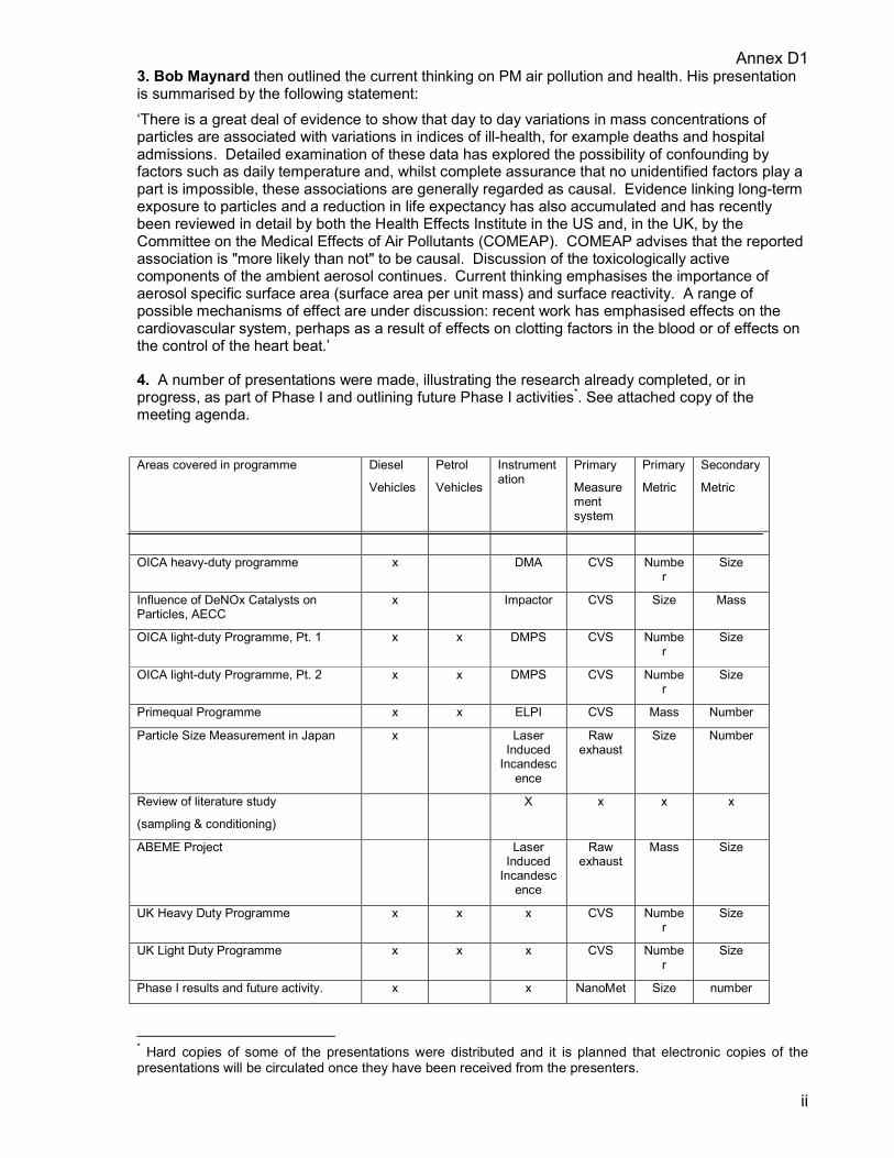
Annex D1
ii
3. Bob Maynard then outlined the current thinking on PM air pollution and health. His presentation is summarised by the following statement: ‘There is a great deal of evidence to show that day to day variations in mass concentrations of particles are associated with variations in indices of ill-health, for example deaths and hospital admissions. Detailed examination of these data has explored the possibility of confounding by factors such as daily temperature and, whilst complete assurance that no unidentified factors play a part is impossible, these associations are generally regarded as causal. Evidence linking long-term exposure to particles and a reduction in life expectancy has also accumulated and has recently been reviewed in detail by both the Health Effects Institute in the US and, in the UK, by the Committee on the Medical Effects of Air Pollutants (COMEAP). COMEAP advises that the reported association is "more likely than not" to be causal. Discussion of the toxicologically active components of the ambient aerosol continues. Current thinking emphasises the importance of aerosol specific surface area (surface area per unit mass) and surface reactivity. A range of possible mechanisms of effect are under discussion: recent work has emphasised effects on the cardiovascular system, perhaps as a result of effects on clotting factors in the blood or of effects on the control of the heart beat.’
4. A number of presentations were made, illustrating the research already completed, or in progress, as part of Phase I and outlining future Phase I activities*. See attached copy of the meeting agenda. Areas covered in programme Diesel
Vehicles
Petrol
Vehicles
Instrumentation
Primary
Measurement system
Primary
Metric
Secondary
Metric
OICA heavy-duty programme x DMA CVS Number
Size
Influence of DeNOx Catalysts on Particles, AECC
x Impactor CVS Size Mass
OICA light-duty Programme, Pt. 1 x x DMPS CVS Number
Size
OICA light-duty Programme, Pt. 2 x x DMPS CVS Number
Size
Primequal Programme x x ELPI CVS Mass Number
Particle Size Measurement in Japan x Laser Induced
Incandescence
Raw exhaust
Size Number
Review of literature study
(sampling & conditioning)
X x x x
ABEME Project Laser Induced
Incandescence
Raw exhaust
Mass Size
UK Heavy Duty Programme x x x CVS Number
Size
UK Light Duty Programme x x x CVS Number
Size
Phase I results and future activity. x x NanoMet Size number
* Hard copies of some of the presentations were distributed and it is planned that electronic copies of the presentations will be circulated once they have been received from the presenters.
Annex D1
iii
Mike Dunne thanked the presenters, saying that they gave a good overview of what was going on currently within the group. The presentations indicated that there was a broad consensus within the group in what was considered to be the main issue, namely the control of the solid portion of the PM is key, although the nucleation mode should not be ignored. He suggested that measurement systems should be able to work with any test cycle, steady state or transient. He noted comments on the effect of sulphur on fuel and lube oil and suggested that perhaps this parameter should be controlled for type approval testing. In summary, it was suggested that the output of the PMP should, ideally, be a single test procedure and a performance specification for instrumentation. This would be important for maintaining lower costs through competition between instrument manufacturers. He also considered it to be desirable to measure PM in a common test for other pollutants, e.g. by using the existing HD and LD test cycles, however, alternatives would not be ruled out.
5. Chairperson for second day and future meetings Mike Dunne said that since the primary aim of this meeting was to facilitate an exchange of views between the research bodies, it seemed appropriate for the chair of future research meetings to be selected from the research representatives present. In the meantime Claire Holman had agreed to chair the current session until a full time Chairperson could be elected. In response to a question, Mike Dunne explained that this expert group was made up of those actively engaged in particulate measurement and that it would advise the PMP working group. The individual participants will still have to decide on their own views on the direction that their individual research programmes should take, but, hopefully, this expert group will help to develop some commonality. Final decisions will be made by the GRPE. Cor Havenith suggested that perhaps the researchers would prefer to meet without the legislators, however others thought that in order to maintain the focus of the programme it was important for the legislators to be present at future meetings. It was agreed that legislators would be invited to all future meetings. Bernie Frost pointed out that the next GRPE meeting was in January 2002, and that this group should be in a position to report progress. It was therefore decided that the next meeting of this group would be at the end of November, in order to formulate a response. In the subsequent discussion of who would chair future meetings of the group, several participants suggested that Claire Holman should be asked to continue. She indicated that she would be willing to do so. It was agreed that to give participants an opportunity to suggest an alternative chairperson, the position of chair would not be confirmed until shortly before the start of the next meeting. The second day consisted mainly of two open workshops for the discussion of ‘Sampling and Measurement’ and Instrumentation and Calibration’. The objective of the two workshops was to facilitate an exchange of views on the most appropriate means of developing a performance test protocol that could be used to type approve light duty vehicles and heavy duty engines having ultra low PM emissions.
6. Sampling and Measurement 6.1. Particle definitions There was general acceptance that research had shown that the accumulation mode particles were stable and the sampling method really had very little effect on the measurement of them. Conversely nucleation mode particles were greatly affected by the sampling method. Dave Rickeard said that in CONCAWE’s view there is a fundamental split between the accumulation and nucleation modes, and that while the current knowledge of accumulation mode is sufficient for a type approval procedure, nucleation mode still requires study in the laboratory. Mike Dunne suggested that to focus on the control of accumulation particles only seemed to offer the best means for encouraging advanced PM control technology; nucleation particles being too unpredictable. With the health effects being identified with mass and most of the mass being made up of accumulation particles, then the reduction of these particles should have health benefits. However, one consideration to be borne in mind was that the smaller particles might increase in number. John McAughey added that you should always be aware that particle behaviour in real life might not be the same as in the sampling system and that a CVS system may be producing the ‘wrong’ particles. Jürgen Stein said that for engine development, the measurement of accumulation

Annex D1
iv
mode particles was really the only practical option. Therefore, he could support proposals that included the measurement of these particles. The discussion then moved on to views on the definition of accumulation mode particles and if these should be “carbonaceous” or “solid” particles. Rainer Vogt asked if the term ‘carbonaceous’ could be defined. Carbonaceous implied a particle made up mainly of carbon. It was also pointed out that there are other non-carbon solid compounds in the exhaust. It was considered that a better term would be ‘solid particle’, which would include non-volatile in-organic compounds which could be soluble in the liquid inside the lungs. An alternative view was that only elemental carbon should be measured. It was said that a number of instruments were being developed to measure the elemental carbon content of PM in real time. Mike Dunne summed up the discussion as considering that nucleation mode should not be considered during this programme; nevertheless, there was an ongoing need to maintain close contact with medical researchers to ensure that no adverse health implications would arise from this approach. Also, since there was no consensus in the group on the definition of the particle to be measured, we should not make a decision on the definition until the measurement system had been selected.
6.2. Sample conditioning and dilution. With the previous decision to exclude nucleation mode particles from investigation, the sample conditioning issue was greatly simplified. Sampling from the raw exhaust or through a diluter would both be practical. The raw exhaust method usually requires the measurement of exhaust gas flow, but Jürgen Stein said that there were systems being developed in Japan and by LTT that would remove this need and make this method more suitable for testing. Jon Andersson made the point that since the accumulation mode is not affected by dilution the use of a CVS would be a practical way for the repeatable measuring of PM, without having to know the exhaust flow. Stephan Schraml pointed out that the LII laser device could measure dilute and raw exhaust gas equally effectively. The discussion then moved on to the issue of which parameters should be measured. It was recognised that although the health effects were related to PM mass, this may be a proxy for particle numbers or specific surface area. John McAughey made the point that it should not be assumed that air quality targets would always be set in terms of grams of PM10. In the future, with greater understanding of the mechanisms of effect, there may be a mass and integrated number limit. There is also evidence, as mentioned by Bob Maynard, that particulate surface area may be important. The need for specifying the size distribution was discussed; the consensus being that it would not be necessary, as the likely distribution would be more or less constant. Stefan Carli said that there was a good correlation between number and mass if a thermodenuder was used to condition the sampling stream. It was agreed that the issue of mass and number deserved further discussion at a later date, when the data from some current studies would be available. Members of the group were also asked to collect data on this subject for consideration at the next meeting. It was agreed that a period would be allocated at the next meeting of the group to discuss this topic.
7. Instrumentation and Calibration 7.1. Instrumentation 7.1.1. Parameters, Cycles, Resolution and Robustness There are a number of instruments that may be suitable for the measurement of accumulation mode particles. It was suggested that a matrix of the possible instruments should be made, this would contain a critical review of each instrument. Leif-Erik Schulte mentioned a report that contained a similar table. Jürgen Stein said that this table would be circulated shortly and that it may be possible to circulate the full report before the next meeting. Mike Dunne asked that the members of the group to consider critical comments on the table and to bring these to the next meeting. A discussion took place over the requirements of the instrumentation. A number of members stated that whatever was required for the type approval test, engine development required an instrument that could resolve transients. Mike Dunne said that it was up to industry which instrumentation they bought for development purposes but, for type approval instrumentation, the cost would be an important consideration. For example an instrument that integrates over a complete transient cycle,

Annex D1
v
and costs 25% of another that can give second by second measurement may be sufficient for type approval. The industry members said that the transient capability was important, especially for off cycle measurements, as required by the EPA. After further discussion it was decided that the minimum time resolution for instrumentation should be 1 Hz. It was also decided that the instrumentation should be able to be used for measuring PM from both SI and CI engines. For the robustness requirement it was noted that the instruments might be required to operate continuously for several hours without attention. This operating condition would be particularly severe if raw exhaust were being sampled. It was agreed that members would give the robustness criteria some thought outside the meeting, and the discussion would continue at the next meeting
7.1.2. Precision and detection limits Mike Dunne stated that as an initial guide any future instrumentation should be able to resolve emissions at levels at or below that from TWC equipped petrol cars and DPF equipped diesel vehicles. Part of the research in phase I would be to refine the requirements. Jürgen Stein said that they had done some tests with 2ppm sulphur fuel in which the reproducibility of the current method was shown to be good. He will circulate the data when it becomes available. This data would show that current methods could potentially resolve down to 0.01 g/kWh. Cor Havenith said that the aim should be for instrumentation to resolve a level 50% lower than existing PM emissions. Claire Holman drew the discussion to a close by saying that this is an area that we should return to a later meeting.
7.2.Calibration 7.2.1. Reference materials
The point was made that mass calibration was comparatively easy to do, whilst number calibration was much more difficult. John McAughey made the point that number or mass concentration standards have potential problems, for example; the calibration materials may not be the same as the PM to be measured and that may affect the measurements. Calibration would be much simpler for integrated measurement instruments. He went on to say that the UK Government’s Valid Analytical Measurement (VAM) programme was looking at this problem. Gerhard Pohlmanne said that there was research in Germany in this area that may assist. Colin Dickens said that although number calibrations were difficult there are sometimes other parameters that can be measured for calibration purposes. At this point Claire Holman drew the meeting to a close and thanked everyone for attending.
8. Next meeting 29th and 30th November 2001, location to be confirmed. Participants were asked to consider whether they could host the next meeting.
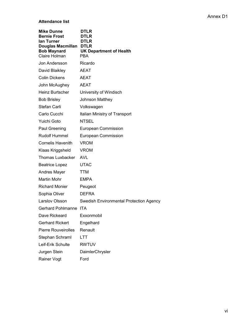
Annex D1
vi
Attendance list Mike Dunne DTLR Bernie Frost DTLR Ian Turner DTLR Douglas Macmillan DTLR Bob Maynard UK Department of Health Claire Holman PBA Jon Andersson Ricardo David Blaikley AEAT Colin Dickens AEAT John McAughey AEAT Heinz Burtscher University of Windisch Bob Brisley Johnson Matthey Stefan Carli Volkswagen Carlo Cucchi Italian Ministry of Transport Yuichi Goto NTSEL Paul Greening European Commission Rudolf Hummel European Commission Cornelis Havenith VROM Klaas Kriggsheld VROM Thomas Luxbacker AVL Beatrice Lopez UTAC Andres Mayer TTM Martin Mohr EMPA Richard Monier Peugeot Sophia Oliver DEFRA Larslov Olsson Swedish Environmental Protection Agency Gerhard Pohlmanne ITA Dave Rickeard Exxonmobil Gerhard Rickert Engelhard Pierre Rouveirolles Renault Stephan Schraml LTT Leif-Erik Schulte RWTUV Jurgen Stein DaimlerChrysler Rainer Vogt Ford

Annex D2
i
GRPE ad hoc group – Particle Measurement Programme (PMP) (Research Group Meeting #2)
Meeting: Essen – November 29th – 30th. Place: RWTÜV Fahrzeug GmbH
AdlerStrasse 7 D-45307
Essen Attendance List See Annex A.
Representatives attended the meeting from the UK, Italy, Sweden, France, Germany, Switzerland and JASIC together with experts from OICA, CLEPA, AECC, CONCAWE and also other European research organisations.
1. Confirmation of the minutes of the last meeting (London July 31st – August 1st). i) Olsson requested that Sweden’s interest in the characteristics and chemical composition of
particulates with respect to health effects be recorded. ii) With respect to the table of research programmes listed in section 4, the following
amendments were made: � The OICA Light-duty Programme (Part 2) included ELPI, CPC and Gravimetric
measurement in addition to the DMPS. � The entry “Primequal Programme” should refer only to “ELPI Evaluation”. � The instrumentation in the “Particle Size Measurement in Japan” should read “Laser
Extinction”.
2. Development of assessment criteria. Following on from the debate in London, some delegates wanted to discuss the definition of the particulate to be measured before considering the instrumentation. After a short debate it was agreed that the objective is to measure the “solid particle” but that, as this was an imprecise term, the definition of what would be measured would be determined from the final measurement system(s). In response to concerns that the programme would select systems for later use in type approval, Frost again made clear that this was not the case. He reminded the group that the objective was to explore the potential for an improved method of measurement and to evaluate those systems that, at present, offered the best potential by measuring emissions from the latest available engine technologies. Any changes to type approval would come as a result of a political demand and would, if adopted, be expressed in performance terms thereby allowing the widest possible commercial opportunity.
i) Instrumentation matrix. A model matrix contained in Section 6.7 of the Swiss Literature Study (April 2001) was used as the basis for discussion. Mayer gave a brief overview of the matrix but cautioned that it had been constructed for off-road applications and may therefore not be fully compatible with the needs of PMP. Of the eleven column titles in the model, two received particular discussion. The title “Field Application” raised the question of the suitability of a system for in-service compliance. Stein suggested that this was an important point for industry who recognised in-service compliance as an issue for the future. Schulte was uncertain whether the entry referred to “in-service compliance” in the context of the type approval requirements or “Inspection and Maintenance” in the context of roadworthiness inspection. It was agreed that, although not a

Annex D2
ii
primary objective, an assessment of a system’s suitability for ISC and/or I&M would be of value and that an individual column for each point would be included in the matrix. With respect to “Stability”, Mayer explained that this represented repeatability, reproducibility and accuracy. The need to distinguish accuracy from precision was raised by Stein who quoted accuracy as being the deviation of the instrument value from the calibration value (ISO 16183) whilst precision was stated as 2.5 σ of 10 repetitive measurements. No agreement was reached and it was agreed not to include this in the matrix at this time. It was also agreed that in the absence of data it would not be appropriate to include reproducibility in the matrix for Phase I. Olsson asked that the remarks column should include references to suitability for chemical composition assessment. Some delegates questioned the mandate of the group to explore this parameter but Rodt argued that the mandate did not prevent exploration of additional criteria within individual evaluation programmes. It was agreed that the remarks column could contain any relevant comment. As an output the group developed a 19-column matrix in which column 2 (Instrument) was completed as indicated in the following table.
1) Instrument 2) Definition CPC Condensation Particle Counter.
DMS Differential Mobility Spectrometer.
DC Diffusion Charging System.
EDB Electrical Diffusion Battery.
PAS Photoelectric Aerosol Sensor.
ELPI Electrical Low Pressure Impactor.
LII Laser Induced Incandescence.
PASS Photo Acoustic Soot Sensor.
TEOM Tapered Element Oscillating Microbalance.
QCM Quartz Crystal Microbalance.
Gravimetric Filter based mass measurement.
[DEKATI] [Development concepts for mass or active surface measurement].
[Coulometric Analysis] [Ref. Horiba Mexa-1220PM - used as reference for ABEME project].
In order to aid completion by others the group also took the opportunity to complete the detail of the gravimetric instrument row.
ii) Sampling and Conditioning Matrix. The group explored various options that may be employed by laboratories for sampling and conditioning. In order to reduce the complexity of the matrix delegates were asked to indicate the systems that they were actively looking at and that were likely to be put forward for consideration in Phase II. From this eight sampling system combinations were identified, namely: 1. CVS (Constant Volume Sampling). 2. Modified CVS 3. CVS + Treatment (e.g. Thermodenuder) 4. CVS + CRS (Constant Ratio Sampling) 5. CVS + CRS + Treatment 6. Raw Full Flow
Annex D2
iii
Partial Flow 7. Tailpipe + CRS 8. Tailpipe + CRS + Treatment Some delegates considered that some of these combinations would be unsuitable for type approval work due to the calibration burden but that it would soon become recognised which systems those were. For the purposes of the matrix the group agreed to refer to six system properties: 1. Full/Partial Flow – Raw. 2. CVS yes/no? 3. CRS yes/no? Specify. 4. Treatment? Specify. 5. Dilution Ratio Range. 6. Dilution Parameters. (temp. humidity etc.) As system repeatability is dependant upon the instrumentation employed, individual columns were introduced into the conditioning and sampling matrix that related back to the instruments listed in the instrument matrix (each defined instrument be ascribed a number). Mayer requested that an expert group be formed to develop calibration standards. Frost did not support this request as the group had already indicated that for Phase II the manufacturer’s calibration procedure would be employed and that for any future legislative purposes it was more likely that ISO would be requested to develop procedures. Frost agreed to finalise the structure of the matrices and to circulate them electronically to members of the Research Group for completion (Annex B). The Research Group agreed to provide Frost with their completed returns by December 17th. The returns would be consolidated and distributed with the minutes of the meeting.
3. System Validation. The discussion concerned whether Phase II of the programme should be conducted as a traditional Round-Robin with vehicles/engines being transported from laboratory to laboratory or whether the candidate systems should be transported and exposed to resident vehicles/engines (multi-site evaluation). Stein felt that it was premature to consider this and that a clear idea of the systems to be tested was necessary before a decision could be made. However, he was concerned that the multi-site evaluation (MSE) approach would not provide reproducibility data. Mayer agreed that true reproducibility would not be shown but argued that the MSE approach would provide repeatability data at each site and that site to site repeatability could be compared. Schulte considered that the MSE approach had benefits in that it would expose the systems to a wider range of engines and technologies. After further exchanges Holman concluded that the majority considered that the MSE approach had merit and that a classical Round-Robin should be considered as Phase III not Phase II. Mayer confirmed that any validation should be conducted using regulated test cycles but also considered that a range of fuels, including biodiesel, should be evaluated. He also sought an indication from the vehicle industry as to whether or not they would be able to provide vehicles/engines. In response to a request from Andersson for EIV/[V] technologies, Kasper suggested that this could be represented using a trap and by-pass. Andersson and Schulte questioned whether this approach would truly represent post-Euro IV technology. Industry was requested to advise GRPE of the potential for them to provide suitable technology for the programme. OICA considered that they would not be able to do so for the January meeting of GRPE as there was insufficient time for their association to discuss the request.
4. Demonstration.

Annex D2
iv
Laser Induced Incandescence (LII). The Group took the opportunity to visit the RWTÜV emissions laboratory and observe the LII system operating on a heavy-duty engine.
5. Presentations. Dr Haisch gave a presentation on the Photo-acoustic Soot Sensor (PASS). Further details can be obtained from, Fax + 49 89 7095 7980 Yuichi Goto made a presentation concerning “Optimisation of measuring methods for particulate size distribution”. This was based on an interim report on the project. Further detail from, [email protected] Roger Westerholm returned to the issues raised by Sweden during the meeting with a presentation on “PAH emissions from Vehicles”. Dr. Westerholm can be reached at, [email protected]
6. Future Meetings. Frost indicated that the next meeting would be the meeting of the PMP group immediately prior to the full GRPE session in Geneva. The meeting was scheduled for the afternoon of Wednesday January 16th. He indicated that he was attempting to extend the meeting to a full day but that he was uncertain as to whether this could be achieved. He confirmed that if the meeting was to be extended he would advise the group. He also confirmed that the minutes of both the research workshops would be circulated in advance of the Geneva meeting. Further meetings of the Research group would be dependent upon the views of the PMP group. BF - January 2002

Annex D2
v
Attendance List – Essen 29/30 November 2001
Name Andersson Jon Berger Heinz Bomel Nathalie Bosteels Dirk Carli Stefan Dr. Christiansson Jan Cucchi Carlo Dickens Colin Feest Andy Dr. Frost Bernie Haisch Dr. Goto Yuichi Hansson Hans-Christen Holman Claire Dr. Kasper Markus Dr Koga Nobuhiko Jain Gordo Dr Jürgen Stein Lopez Beatrice Luxbacher Thomas Dr Mayer Andreas Olsson Larsolov Pohlmann Gerhard Rickert Gerhard Rodt Stefan Rouveirolles Pierre Dr. Schraml Stephan Schulte Leif-Erik Thompson Neville Trassaert Patrick Mr Vogt Claus Dieter Vogt Rainer Westerholm Roger Dr
Affiliation Ricardo Swiss Federal Roads Authority Renault VI AECC OICA / VW Swedish EPA Italian Ministry of Transport AEA Technology AEA Technology DTLR Technical University of Munich JASIC Stockholm University Peter Brett Associates Matter Engineering Toyota Ministry for the Environment (Bonn) OICA / Daimler Chrysler AG UTAC AVL TTM / Buwal Swedish EPA FhG Inst. of Toxicological & Aerosol Research Engelhard Technologies Federal Environmental Agency Renault Cars ESYTEC Gmbh RWTÜV CONCAWE CLEPA NGK OICA/ Ford Stockholm University
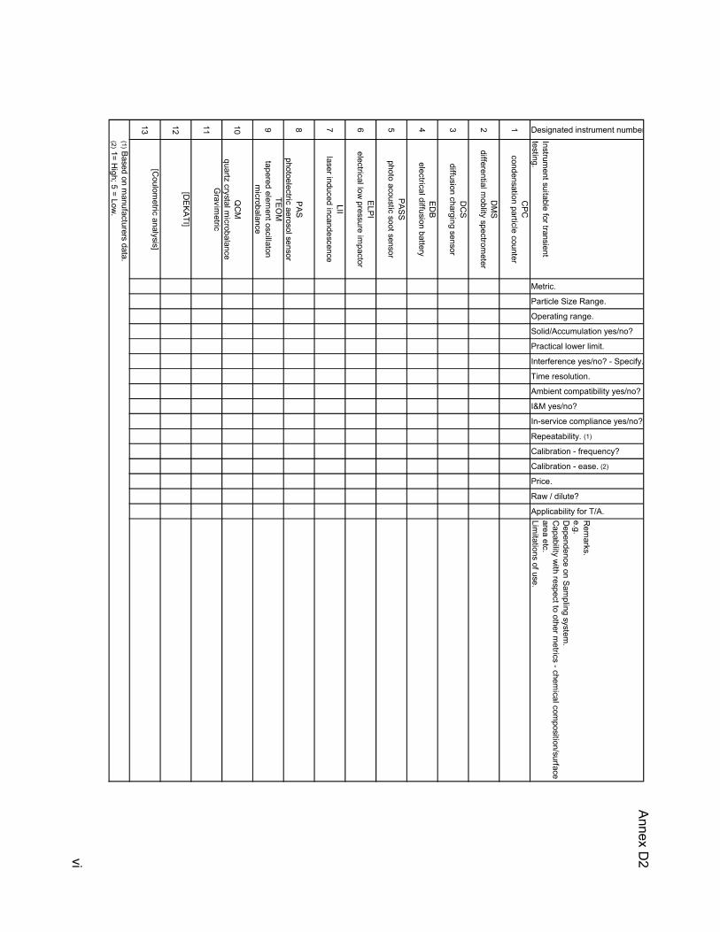
Annex D2
vi
Designated instrument number
Instrument suitable for transient
testing.
Metric.
Particle Size Range.
Operating range.
Solid/Accumulation yes/no?
Practical lower limit.
Interference yes/no? - Specify.
Time resolution.
Ambient compatibility yes/no?
I&M yes/no?
In-service compliance yes/no?
Repeatability. (1)
Calibration - frequency?
Calibration - ease. (2)
Price.
Raw / dilute?
Applicability for T/A.
Rem
arks.e.g.D
ependence on Sampling system
.C
apability with respect to other m
etrics - chemical com
position/surface area etc.Lim
itations of use.
1C
PCcondensation particle counter
2D
MS
differential moblity spectrom
eter
3D
CS
diffusion charging sensor
4ED
Belectrical diffusion battery
5PASS
photo acoustic soot sensor
6ELPI
electrical low pressure im
pactor
7LII
laser induced incandescence
8P
ASphotoelectric aerosol sensor
9TEO
Mtapered elem
ent oscillaton m
icrobalance
10Q
CM
quartz crystal microbalance
11G
ravimetric
12[D
EKATI]
13[C
oulometric analysis]
(1)Based on manufacturers data.
(2)1= High; 5 = Low
.

Annex D2
vii
Nam
e
Full flow/partial flow (raw).
CVS yes/no?
CRS yes/no. Which?
Treatment (which?) (1)
Dilution ratio range.
Dilution parameters (2)
System # [1]
System # [2]
System # [3]
System # [4]
Applicability for T/A.
Size dependant recovery.
Influence of conditions. (4)
Exhaust flow determination yes/no?
Artefacts - identify.
Maintenance requirement.
Complexity system/sampling/processing. (5
Volatiles Removed? - Yes/no?
isokinetic sampling yes/no?
Instrument dependancy. (6)
Influence of dilution.
Cost.
(1) Thermodenuder, heated sam
ple/dilution etc.State Tem
perature(2) e.g.Tem
perature, humidity, dilution rate, ratio etc.
(3) CO
V.(4) e.g. Am
bient concentration, RH
, temperature (am
bient/exhaust).(5) 1 = H
igh; 10 = Low.
(6) Instrument identifier from
table 1.
System R
epeatability. (3)Properties.

Annex D3
i
GRPE ad hoc group – Particles Measurement Programme (PMP) (Research Group Meeting #3)
Meeting: London – March 18th – 19th 2002. Place: Cabinet Office 70 Whitehall London Attendance List See Attachment 1. Representatives attended the meeting from the UK, Italy, Sweden, France, Germany, Switzerland and JASIC. Research experts from OICA, AECC and CONCAWE together with government sponsored experts from other European research organisations attended. HORIBA, DEKATI and Cambustion represented instrument manufacturers.
1. Confirmation of the minutes of the last meeting (Essen, November 2001). The minutes were accepted without comment.
2. Health Effects. Rodt recalled that the work of this group was related to the question of the importance of particle size and/or number on human health and was interested to know how this was being addressed. Frost agreed that consideration of the health effects was part of this work although only in the context of monitoring developments in that field. He reminded the group that the Swiss delegation had submitted a report to the group that included a health effects overview and also confirmed that the UK’s Phase I work included a review of the health effects literature. Answering Havenith’s concern about proceeding in the absence of the health effects information Frost recalled that it was always understood that the health effects question was something to address in parallel with the development of a new measuring procedure and that one was not dependant on the other. He reminded the group that the output of the PMP programme would be considered at a political level and that the health effects question would inevitably be part of that consideration. Holman was of the view that no significant development in the knowledge of health effects had emerged during the previous twelve months.
3. Participation: Tour de Table. France conformed that their round-robin programme involving 4 laboratories and both diesel and gasoline light duty vehicles was underway. They were evaluating the ELPI and would contribute their findings to the programme. Sweden confirmed that they were about to start a national programme and that this would probably include both CPC and ELPI operating with a thermodesorber. They would consider the agreed methodology for Phase II of the PMP for their programme. They also confirmed that they would be including chemical analysis of the particles in their work. Switzerland confirmed that they intended to make a comprehensive and simultaneous comparison of a number of instruments at a single laboratory. This programme would take place in Zurich and is scheduled to start in June 2002. They were keen to operate within an integrated international programme and wanted early agreement on a work specification.

Annex D3
ii
UK and Germany confirmed that they had funding for Phase II and that they wanted to reach agreement on a work programme that would form the basis of their projects that would start around June 2002. Japan confirmed their interest in the programme but indicated that they considered that a study of the dispersal characteristics of particles to be important. OICA indicated that they could agree to participate in principle but that the final decision was dependent upon the work specification that had yet to be agreed. AECC confirmed that they could make after treatment systems available but that they did not intend to run an individual programme. CONCAWE confirmed that they could deliver common specification fuel and lubricant although it was not clear whether they could necessarily fund this supply.
4. Core Instruments. 4.1. Carli made a brief presentation of data collected during the ACEA Particulate Programme II. This programme included 7 vehicles (both gasoline and diesel) and assessed a variety of sampling systems using two different fuel sulphur levels. It was argued that the programme had shown a good correlation between particulate mass and particle number and that therefore the PMP study should include a mass based approach. Rodt questioned the ACEA conclusion. He noted that the data represented emissions over a wide mass range and that a significant amount of those data were at values above 0.025 g/km. It was argued that correlation studies could only be valid if they were based upon values at the level that may be expected by future legislation. Mayer agreed that the conclusion that there was a mass/number correlation was questionable and that a reduction in mass does not infer a reduction in number concentration. Frost confirmed that the UK recognised that it was necessary to include a mass based procedure in Phase II and that it was considered that this should be based upon the USA 2007 procedures. He also confirmed that the UK’s Phase I work had concluded that the CPC showed good promise for application on both light-duty and heavy-duty measurement. Mayer confirmed that the Swiss programme would include the Photoelectric Aerosol Sensor (PAS) for mass determination and that they would like to assess the widest possible instrument matrix. France also confirmed that its round-robin programme included a gravimetric approach. Hosier indicated that whilst Ford were not in a position to add specifically to Phase II, they may be in a position to provide a report of work that they were conducting using a TEOM. 4.2. It was agreed that it was unlikely that Phase II could fully implement the USA 2007 standards and that to avoid confusion the approach should be referred to as Enhanced Gravimetric. Developing this thought Stein described the critical elements in the USA 2007 approach. These were:
• The introduction of a cyclone pre-classifier upstream of the filter.
•
The use of 47mm filters having improved filtration efficiency.
•
A new design of filter holder.
• The deletion of the backup filter.
•
Maintenance of the filter at 47 ± 0.5°C.
• A 0.1 µgram microbalance
•
A Class-A clean room for the weighing chamber.

Annex D3
iii
Stein also reminded the meeting that ISO/FDIS 16183 contained detailed procedures that should be considered and cautioned that there were significant changes between the DIS and FDIS versions of this new standard. Hill advised that the filters were available at ~$800/set and that the cyclone pre-classifier was available at ~$1000 - $1200. He considered that with respect to the clean room the real issue was on the management of the filter room temperature and humidity. He considered that the temperature control was difficult and required further development. Flow rate was seen as important. Hill indicated that this may not be as important for carbon it was for SOF. Andersson suggested that flow rate should be maximised to allow for optimal collection whilst Stein considered that individual laboratories should develop their approach and define the outcome in their report. Stein also cautioned that the programme should limit measurement to 1 test/filter as multiple tests can reduce the measured amount. 4.3. The inclusion of the LII instrument in Phase II was discussed. It was not clear whether this instrument would be available in time for its inclusion but this should be clearer in the next few weeks. Operating parameters were also unclear but it was felt that they could be broadly similar to those of the gravimetric approach. 4.4. Lopez explained that in the ELPI programme France was using greased foil collection plates to minimise particle bounce. She also confirmed that the system employed in the programme included a thermodesorber operating at 250°C. Tikkanen suggested that sintered collection plates gave a sharper segregation of size and were even more effective than greased plates, particularly on dry particles that had a greater propensity to bounce. 4.5. Mohr was concerned that Diffusion Chargers exhibited poor comparability between instruments particularly when measuring sub 30nm particles. He considered that this was because of the different charging principles employed by the respective manufacturers. Hands reminded the group that a DC was also the first stage of the ELPI and that therefore DC’s should not be dismissed.
5. Calibration. Vogt was concerned that calibration procedures for CPC, ELPI and DC had to be agreed before the instruments could be evaluated. They argued that this would avoid devoting time on an instrument that, due to calibration, limitations could not be applied for type approval purposes. Andersson felt that similar calibration procedures could be applied to both the CPC and ELPI devices. Mayer explained that the Swiss programme will use the CAST combustion aerosol source which can be used for both size and concentration. He indicated that this provided 2%-5% accuracy and would be suitable for all instruments. Some delegates considered that this was unlikely to be a long term solution due to the cost and availability of CAST and that therefore a more simple approach should be considered – perhaps by validating parameters such as flow and voltage. Dickens indicated that AEAT were developing a calibration standard for use with the SMPS that could be equally valid for other instruments. Whilst not yet complete he was happy to share that work with the group (distributed on the second day). Vogt suggested that to be valid calibration was required before and after each test. Lopez advised that the ELPI programme included a calibration check each month and that there was no drift apparent over this period. Mohr supported a less vigorous approach, he suggested that the programme was not so much interested in minor drift but in significant shifts and that verification should not require onerous calibration routines. Holman acknowledged that calibration was an important issue and that Phase II should be so planned that this parameter was adequately addressed. She encouraged those parties
Annex D3
iv
that were to sponsor further work to agree a common protocol that could maybe have full calibration and calibration check elements.
6. Fuel and Lubricant. 6.1. Hall indicated that CONCAWE were prepared to make fuel of a common specification, broadly in-line with the expectation of post 2005 EU standards, available to the programme. She was not in a position to advise on the cost implications of such a supply but would offer further advice once the volume requirements were more clearly defined. Carli pointed out that in Germany Shell were providing a special high-octane fuel (Optimax) for use with GDI vehicles and that this high octane would be necessary if GDI’s were to be included in the programme. It was suggested that high octane petrol be used as a common fuel for SI engines and Hosier agreed to confirm whether this was acceptable for non-GDI engines (Sec. Note: confirmed). 6.2. Hall confirmed that CONCAWE could in principle also supply lubricant but that they needed further advice with respect to the PMP’s needs. Carli suggested that for light-duty applications the oil specification is not so significant and Stein argued that the lubricant should be as recommended by the engine manufacturer.
7. Test Cycles. Frost indicated that the UK envisaged using the European Transient Cycle for heavy-duty testing and the NEDC for light-duty. This was based upon UK research that had shown greater repeatability over transient cycles than was obtained over steady state cycles. Stein argued that he would want the ESC included if Daimler Chrysler were going to provide engines, he also considered that it would be beneficial, in the Geneva context, to include the US FTP cycle. Havenith requested inclusion of the WHDC, as this would test the suitability of the new procedure for future standards. Mohr argued that testing should include a response test, as this element would not necessarily be tested by the normal regulated cycles. Stein indicated that Daimler Chrysler would definitely not provide engines if their emissions were to be monitored during any element of the ELR test as suggested by Mayer. Schulte suggested that response information was instrument specific and was available anyway, whilst Hands suggested that a change to the inlet aerosol would be a more effective way of determining a response value than the use of an engine.
8. Sampling. 8.1. Thermodesorber. Frost observed that the matrices completed after the Essen meeting had clearly identified control of nucleation particles as being an important issue for all of the instruments listed. He noted that UK research had also highlighted this as an important parameter to control. Andersson explained that Ricardo had evaluated flow rate, inlet temperature and carbon bed temperature as part of their Phase I contribution to the UK programme. He was concerned that the effects of too high a temperature should also be considered as this could, in addition to removing volatiles, affect agglomerate size. Mohr considered that the thermodesorber performance was a function of both the temperature and residence time at that temperature, he suggested that the important temperature was that at the entrance to the absorption element (post heating element). Tikkanen expressed the view that the manufacturer should specify the flow and losses and that DEKATI would suggest 10 litres/min and with an outlet temperature of 250 °C. Pohlmann suggested that laboratories should merely check that the thermodesorber works to the manufacturer’s specification and should monitor the temperature at the inlet and adsorption element inlet.

Annex D3
v
Kasper took the view that there should be a performance specification e.g. a device capable of stripping out particles that would be in vapour phase at temperatures > 250 °C. Mayer suggested extending this approach by distinguishing between vapour phase particles and solids e.g. particles that would be in vapour phase at temperatures > 200 °C + losses ≤30% of the remaining. Vogt considered that it was necessary to validate the performance of a thermodesorber before and after every test, however Andersson indicated that his experience had shown that provided temperature and flow rate were properly controlled the results were quite stable. Most agreed that the condition of the carbon in the adsorption element had to be carefully managed, as there was no obvious sign as to when it was saturated. Again most agreed that this could be predicted on the basis of the density of particles in the sample and the flow volume to which the adsorption carbon had been exposed. Holman concluded that programme sponsors would take note of the comments received and would include assessment of these issues in their programmes.
9. Raw versus Dilute Vogt cautioned that in raw exhaust, flow rate and time alignment was critical. Stein indicated that ISO/FDIS 16183 offered guidance on this point.
10. Vehicle Conditioning. Lopez suggested that for light-duty vehicles the approach set out in Directive 70/220/EEC should be followed, Hosier supported this. For heavy-duty Stein favoured a suitably modified version of the EPEFE protocol for light-duty vehicles. Andersson confirmed that for heavy-duty engines Ricardo include 1.5hrs running prior to testing (low load power curve + test cycle). Andersson also suggested that measurements can vary depending upon the previous use of the system. Lopez confirmed that France had seen reduced particles if the system had already been used in that day. Andersson suggested that if multiple vehicles were being tested it would be advisable to have a consistent sequence so that the preceding vehicle was always the same. The group considered whether GDI vehicles should be tested in the same tunnel as other petrol vehicles. Andersson considered it to be appropriate and also felt that it might be possible to test diesels equipped with particle filters in the same tunnel. Schulte did not feel this latter point to be acceptable. Dickens suggested that the risk of artefacts could be reduced if a dedicated transfer pipe for each vehicle was employed. Vogt opposed this view as he felt that it was better to identify a limitation than to mask it. Mayer suggested that the Swiss programme would include 10 repeat ETC tests for repeatability assessments but Stein considered that 5 – 7 would be statistically acceptable. Schulte requested that a common procedure for statistical validity (ISO 5725) be used.
11. Other. Havenith suggested that it would be helpful if the instrument manufacturers became more involved in the programme and asked who would now take responsibility for drafting the work specifications. In response to Mayer’s indication that he was preparing a specification for the Swiss programme Rodt pointed out the importance of a common specification for Phase II. Frost commented that it had been hoped that this meeting would have gone some way to developing the understanding necessary to draft a common specification. He would arrange for the sponsors of Phase II to come together and agree an approach for Phase II. He would annex an account of that meeting to the minutes. Stein agreed to provide the testing protocols that had been used in previous correlation studies for 16183.

Annex D3
vi
Havenith questioned the timing of the programme objectives. Frost reminded the meeting that the PMP programme was due to report the findings of Phase II to the GRPE in January 2003. He understood that France was already engaged in work and that at least 4 other partners had work programmed for this year that would support the PMP process. He acknowledged that the programme had an ambitious time scale but that none the less there was a desire to deliver the objectives on time. He did not believe that the timing permitted another meeting of the Research Group before the June session of GRPE but hoped that comments on further activities could be provided by mail/e-mail. He agreed that he would circulate further information as it became available. Bernie Frost 22/3/02 Attachments 1. Attendance List 2. DEKATI – Sintered Collection Plates (Instructions) 3. DEKATI – Sintered Collection Plates (Description) 4. DEKATI – Thermodenuder Correction for Losses. 5. DEKATI – ELPI Filters. 6. DEKATI – ELPI Calibration. 7. France – National light-duty work specification.