Particle Identification - CERN...Roger Forty Particle ID (Lecture II) 2. 1. Photon detectors •...
40
Particle Identification ICFA Instrumentation School, Bariloche, 19-20 January 2010 Lecture II: Detectors 1. Photon detectors 2. Cherenkov detectors 3. RICH examples 4. Other PID devices Charged hadron ID is based on the principles described in Lecture I How are they applied in the design of actual detectors?
Transcript of Particle Identification - CERN...Roger Forty Particle ID (Lecture II) 2. 1. Photon detectors •...
Particle Identification
ICFA Instrumentation School, Bariloche, 19-20 January 2010
Lecture II: Detectors
1. Photon detectors2. Cherenkov detectors3. RICH examples4. Other PID devices
Charged hadron ID is based on the principles described in Lecture I How are they applied in the design of actual detectors?

Roger Forty Particle ID (Lecture II) 2
1. Photon detectors• Photon detection is necessary for many of the
detectors performing particle identificationRequirements: single photon sensitivity, high efficiency, good spatial granularity
• Incident photon is (usually) converted to anelectron by the photoelectric effect in a photocathode, typically formed of a combination of alkali metals, eg Sb-Na-K-Cs
• The photoelectron signal needs to be amplified to give a measureable electronic pulse
• Achieved in traditional photomultiplier (PM) by dynode chain → multiplication of the charge at each dynode: eg if number of electrons is tripled on each stage of a 12 dynode chain → Gain = 312 ~ 106
Photomultiplier(cross section)

Roger Forty Particle ID (Lecture II) 3
Detection efficiency• Quantum efficiency: probability that an
incident photon produces a photoelectron Peak value is typically 20 – 30%
• Needs to be multiplied by the collection efficiency: the efficiency for detecting the photoelectron (typically 80 – 90 %)
• Photocathode type is chosen according to the desired spectral sensitivity:
Remember: E = hc/λλ [nm] ≈ 1240 / E [eV]
QE for tubes with multialkali photocathode

Roger Forty Particle ID (Lecture II) 4
Multianode PM• The multianode photomultiplier is a marvel of
miniaturization → up to 64 pixels in a single tube, each with size ~ 2×2 mm2
• Dynode structure formed from a stack of perforated metal foils
• Signal width dominated by fluctuations in the charge multiplication of the first dynodes
Multianode PM (Hamamatsu)
1 photon
Noise
Signal
Roger Forty Particle ID (Lecture II) 5
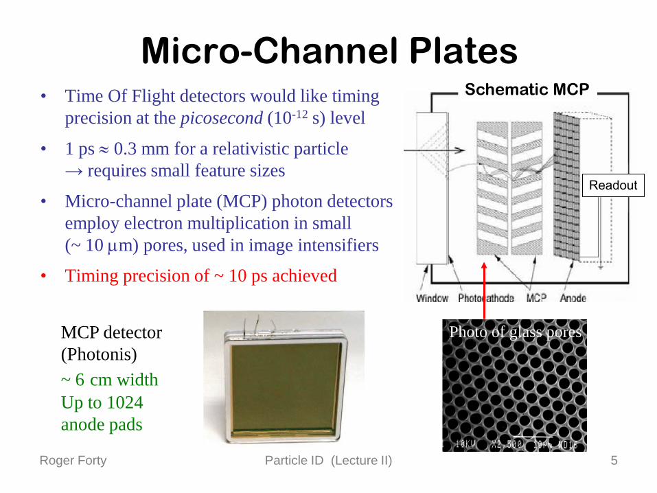
Micro-Channel Plates• Time Of Flight detectors would like timing
precision at the picosecond (10-12 s) level
• 1 ps ≈ 0.3 mm for a relativistic particle → requires small feature sizes
• Micro-channel plate (MCP) photon detectors employ electron multiplication in small (~ 10 µm) pores, used in image intensifiers
• Timing precision of ~ 10 ps achieved
Schematic MCP
Readout
Photo of glass poresMCP detector(Photonis) ~ 6 cm widthUp to 1024anode pads

Roger Forty Particle ID (Lecture II) 6
Silicon PM• Fully solid-state photon detectors are
a very active field of development
• Use a p-n junction in Geiger mode (above the breakdown voltage) → large gain, binary signal, long recovery
• An array of ~ 100 such elements is used to provide a single pixel
• Advantages: very compact, high quantum efficiencyDisadvantages: high noise, n damage?
Traditional PM

Roger Forty Particle ID (Lecture II) 7
Hybrid Photon Detectors• Development from the photomultiplier:
Instead of using a dynode chain to provide the amplification, accelerate the photoelectrons with electric field and use a silicon sensor as anode
• It takes 3.6 eV to create an electron-hole pair in siliconUsing an accelerating voltage 20 kV → ~ 5000 e− signal, enough to be detected using modern low-noise electronics
• Advantages: very good energy resolution (sensitivity to number of individual photons), silicon sensor can be segmented as required
Disadvantages: high voltage, ion feedback → requires very good vacuum
∆V
photocathode
focusing electrodes
siliconsensor
electron
Roger Forty Particle ID (Lecture II) 8
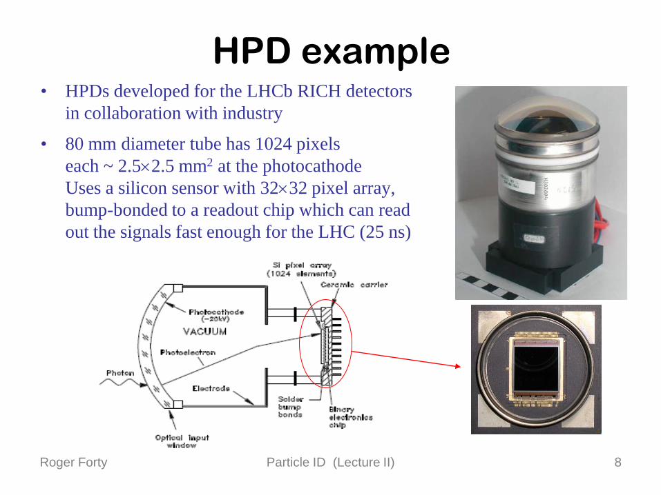
HPD example• HPDs developed for the LHCb RICH detectors
in collaboration with industry
• 80 mm diameter tube has 1024 pixels each ~ 2.5×2.5 mm2 at the photocathodeUses a silicon sensor with 32×32 pixel array, bump-bonded to a readout chip which can read out the signals fast enough for the LHC (25 ns)
Roger Forty Particle ID (Lecture II) 9
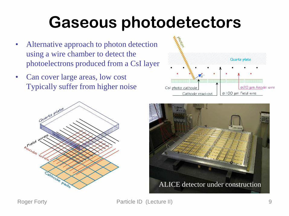
Gaseous photodetectors• Alternative approach to photon detection
using a wire chamber to detect the photoelectrons produced from a CsI layer
• Can cover large areas, low costTypically suffer from higher noise
ALICE detector under construction
Roger Forty Particle ID (Lecture II) 10
2. Cherenkov detectors• Recall from first lecture: Cherenkov light is emitted with cos θC = 1 / βn
• The light is produced equally distributed over photon energies, which when transformed to a wavelength distribution implies it is peaks at low wavelengths – it is responsible for the blue light seen in nuclear reactors
• The number of photons detected in a device is:
Npe = α2 L ∫ ε sin2 θC dE, where α2 = 370 cm-1eV-1
remec2 remec2
L is the length of the radiator mediumε is the efficiency for detecting the photons
• There is a threshold for light production at β = 1/n– Tracks with β < 1/n give no light – Tracks with β > 1/n give light
Roger Forty Particle ID (Lecture II) 11
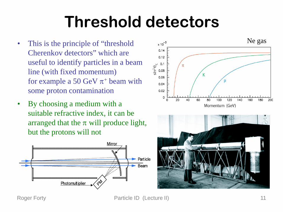
Threshold detectors• This is the principle of “threshold
Cherenkov detectors” which are useful to identify particles in a beam line (with fixed momentum)for example a 50 GeV π+ beam with some proton contamination
• By choosing a medium with a suitable refractive index, it can be arranged that the π will produce light, but the protons will not
Ne gas

Roger Forty Particle ID (Lecture II) 12
Ring imaging• Threshold counters just give a yes/no answer, and are less useful when the
tracks have a wide momentum rangeHowever, more information can be extracted from the Cherenkov angle
• From a classic paper by J. Seguinot and T. Ypsilantis [NIM 142 (1977) 377]the Cherenkov cone can be imaged into a ring, using a spherical mirror
• Measuring the ring radius r allows the Cherenkov angle θC to be determined
Spherical mirrorradius R
Detector planeradius R/2
TrackInteraction point
× r
r ~ R θC /2
Photons
Radiatormedium

Roger Forty Particle ID (Lecture II) 13
RICH detectors• “Ring-Imaging Cherenkov” → RICH
• Original concept has practical limitation: the photon detectors would be sited in the middle of the acceptance, their material would interfere with tracking/calorimetery
• Practical implementations typically use a tilted focussing mirror, to bring the ring images out of the acceptance
• Cross-section through RICH-1 of LHCb
• Makes use of two separate radiators:C4F10 gas and silica aerogel (a solid)A second (flat) mirror is used to limit the size of the detector along the beam axis

Roger Forty Particle ID (Lecture II) 14
Radiators• A wide variety of materials are used as
RICH radiators
• Refractive index selected according to the momentum region to be covered
• Aerogel (n = 1.03) is a very light material made from silica SiO2, good for low momenta p < 10 GeV
• C4F10 (n = 1.0014), a fluorocarbon gas, good for intermediate momenta
• CF4 (n = 1.0005) is used in RICH-2 for high momentum region p > 20 GeV
• Fluorocarbon gases are chosen because they have a low chromatic dispersioni.e. n does not depend strongly on Eγ
Roger Forty Particle ID (Lecture II) 15
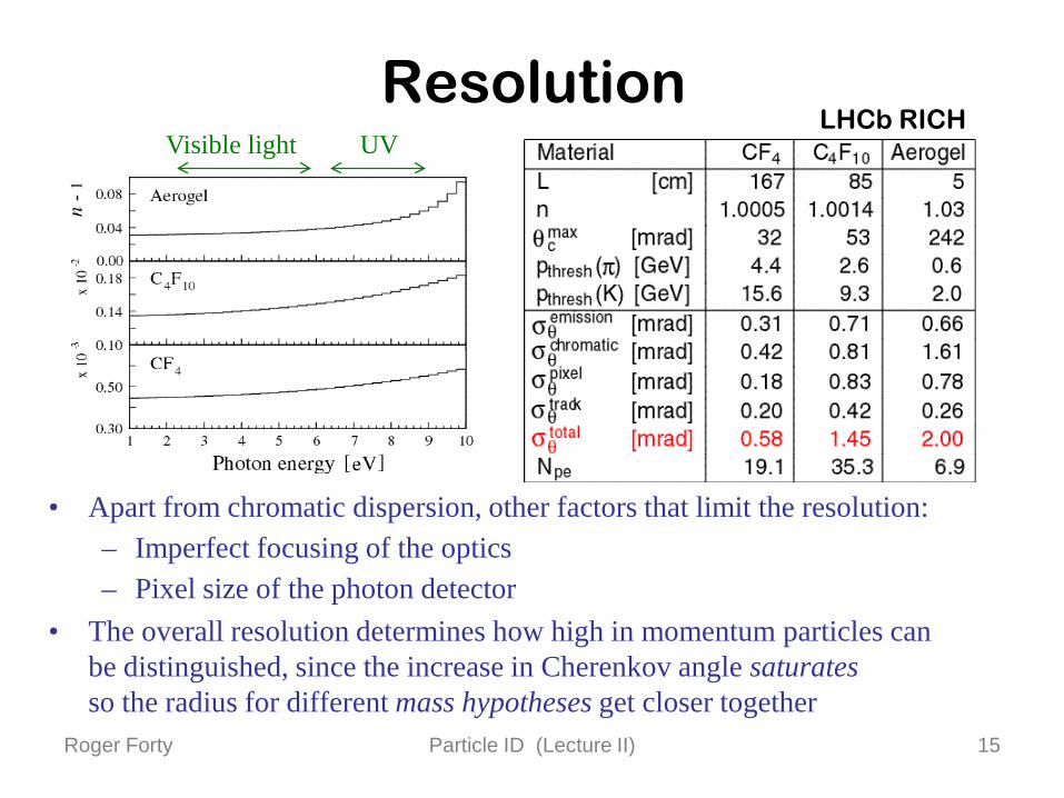
Resolution
• Apart from chromatic dispersion, other factors that limit the resolution:– Imperfect focusing of the optics– Pixel size of the photon detector
• The overall resolution determines how high in momentum particles can be distinguished, since the increase in Cherenkov angle saturatesso the radius for different mass hypotheses get closer together
Focusing
TotalPixel
Chromatic
(mrad)
Visible light UVLHCb RICH

Roger Forty Particle ID (Lecture II) 16
Mirrors• The optics of a RICH detector
requires mirrors, with high reflectivity to avoid losing photons
• Traditional construction uses a glass substrate, with coating of Al for the reflective surface and then MgF2 or SiO2 for protection Reflectivity ~ 90%
• In applications where minimizing the material budget is important, carbon fibre or Be substrates are used
eg the RICH-1 spherical mirror is made from carbon fibre, ~ 1% X0 Inside RICH-1
Roger Forty Particle ID (Lecture II) 17
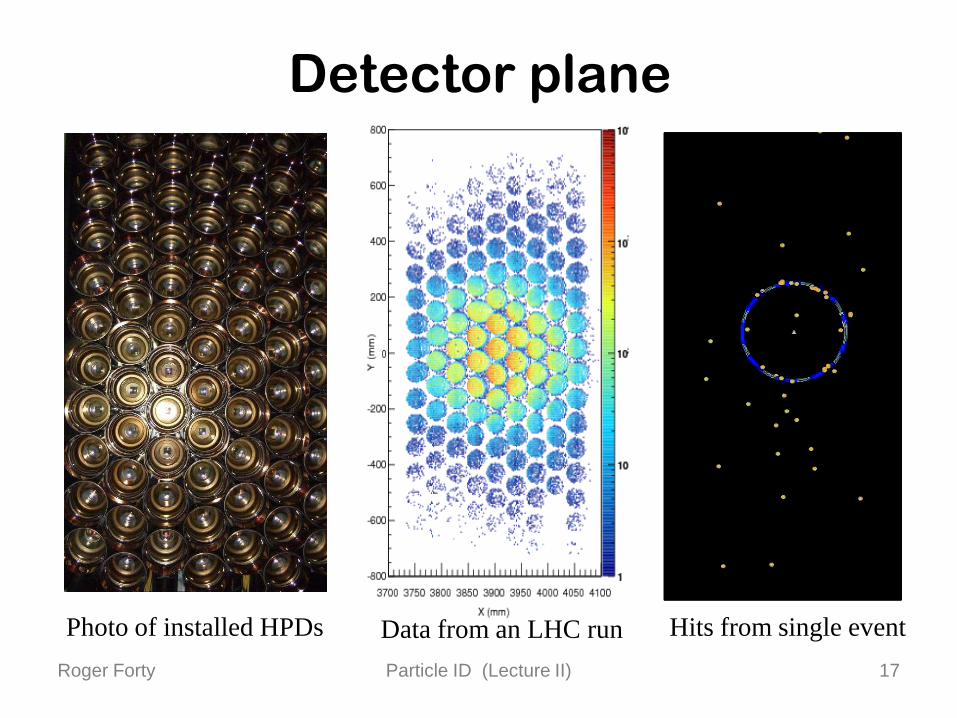
Detector plane
Photo of installed HPDs Data from an LHC run Hits from single event
Roger Forty Particle ID (Lecture II) 18
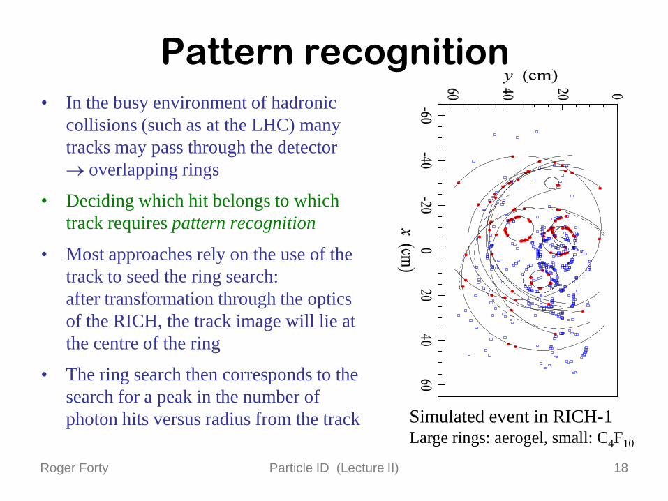
Pattern recognition• In the busy environment of hadronic
collisions (such as at the LHC) many tracks may pass through the detector→ overlapping rings
• Deciding which hit belongs to which track requires pattern recognition
• Most approaches rely on the use of the track to seed the ring search: after transformation through the optics of the RICH, the track image will lie at the centre of the ring
• The ring search then corresponds to the search for a peak in the number of photon hits versus radius from the track Simulated event in RICH-1
Large rings: aerogel, small: C4F10

Roger Forty Particle ID (Lecture II) 19
Particle separation• Separating two particle types using the
signal from a RICH detector is illustrated for K and π from a test beam
• ~ Gaussian response, σθ ~ 0.7 mradPeaks are separated by 4 mrad = 6 σθ
Generally: Nσ = |m12 – m2
2|2 p2 σθ √n2-1
• Adjusting the position of the cut placed between the two peaks to identify a ring as belonging to a K or π gives a trade-off between efficiency and misidentification
• Studied in detail for the LHCb RICH system using Monte Carlo simulation
LHCb simulation
Test beam
Roger Forty Particle ID (Lecture II) 20
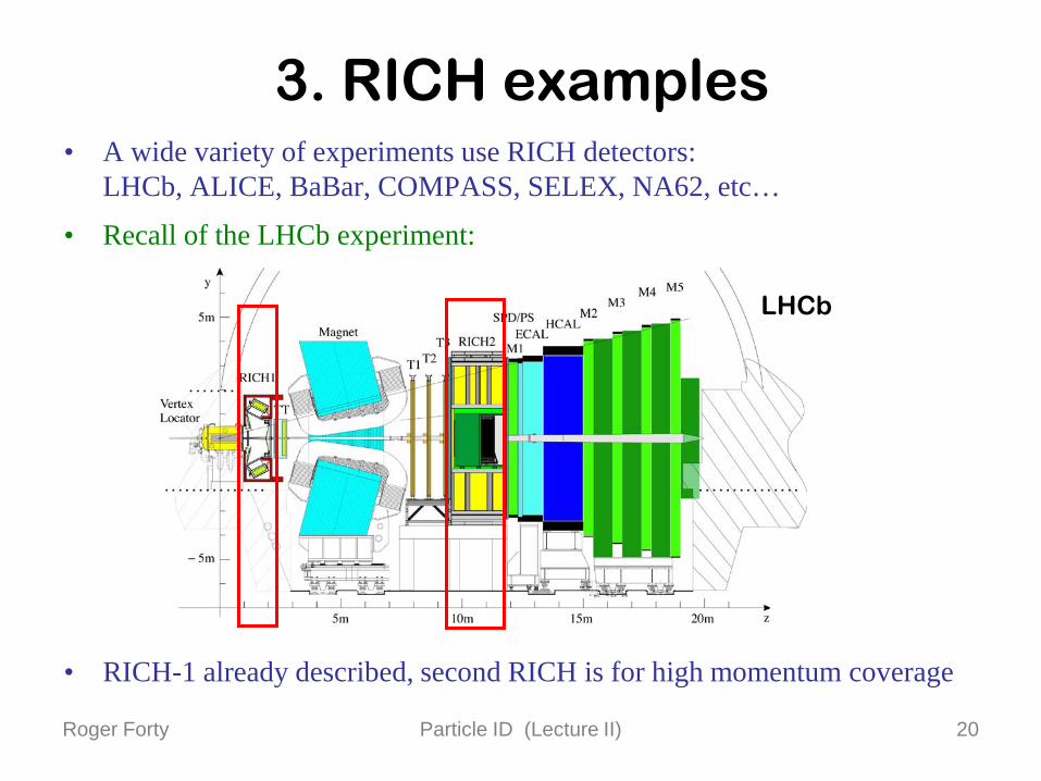
3. RICH examples• A wide variety of experiments use RICH detectors:
LHCb, ALICE, BaBar, COMPASS, SELEX, NA62, etc…
• Recall of the LHCb experiment:
• RICH-1 already described, second RICH is for high momentum coverage
LHCb

Roger Forty Particle ID (Lecture II) 21
LHCb RICH-2• Very large detector as sited
downstream in the spectrometer
• Uses glass mirror substrates,CF4 gas radiator
Flat mirrorsSpherical Mirrors
Photon Detectors + Shielding
Central Tube
Support Structure
7.2 m
Inside RICH-2

Roger Forty Particle ID (Lecture II) 22
ALICE HMPID• Uses liquid radiator, gaseous photon detectors
“Proximity focusing” with stand-off distance
• Used for high-momentum PID, over only part of the solid angle
HMPID
Detected ring image

Roger Forty Particle ID (Lecture II) 23
DIRC detector• Detector of Internally Reflected Cherenkov light
(BaBar experiment) uses quartz as the radiator
• Light is trapped inside quartz bars by total internal reflection → takes up little radial space
• TIR preserves the angles of the photonsDetection at end of bars using PM array
Law of refraction:n1 sin θ1 = n2 sin θ2n1= 1.45 (quartz) n2 ≈ 1.0 (air)
Total internal reflectionif θ1 > sin-1(1/1.45) ≈ 44º
n1
n2θ2
θ1

Roger Forty Particle ID (Lecture II) 24
DIRC performance• Due to different geometry, signal patterns
are hyperbolic rather than rings
• Good performance at low momentum
In timeOut of time

Roger Forty Particle ID (Lecture II) 25
Ice-Cube• Neutrino experiment in the ice of the South Pole,
detecting Cherenkov light from up-going neutrinos that have traversed the earth, and then νµN → µX
• Others use similar technique with sea water asthe target/radiator (ANTARES, NESTOR, etc)
• Very challenging deployment!
Optical module

Roger Forty Particle ID (Lecture II) 26
Super-Kamiokande• Neutrino detector using water as
the target and detector medium
• Clear separation (real data) of µ- and e-like rings (showering)Misidentification rate < 1%
µ
e
Roger Forty Particle ID (Lecture II) 27
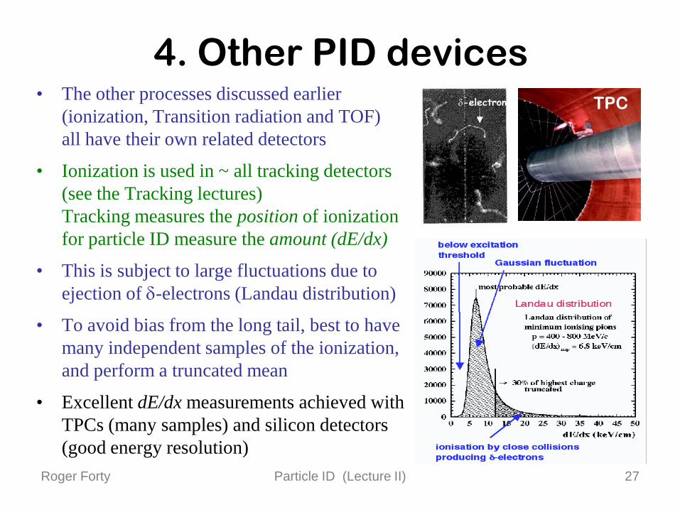
4. Other PID devices• The other processes discussed earlier
(ionization, Transition radiation and TOF) all have their own related detectors
• Ionization is used in ~ all tracking detectors (see the Tracking lectures)Tracking measures the position of ionization for particle ID measure the amount (dE/dx)
• This is subject to large fluctuations due to ejection of δ-electrons (Landau distribution)
• To avoid bias from the long tail, best to have many independent samples of the ionization, and perform a truncated mean
• Excellent dE/dx measurements achieved with TPCs (many samples) and silicon detectors (good energy resolution)
TPC
Roger Forty Particle ID (Lecture II) 28
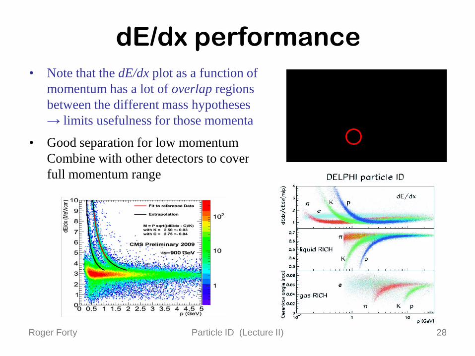
dE/dx performance• Note that the dE/dx plot as a function of
momentum has a lot of overlap regions between the different mass hypotheses → limits usefulness for those momenta
• Good separation for low momentumCombine with other detectors to cover full momentum range
Roger Forty Particle ID (Lecture II) 29
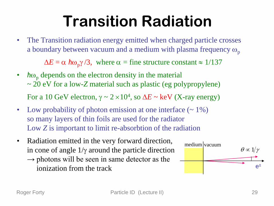
Transition Radiation• The Transition radiation energy emitted when charged particle crosses
a boundary between vacuum and a medium with plasma frequency ωp
∆E = α hωpγ /3, where α = fine structure constant ≈ 1/137
• hωp depends on the electron density in the material ~ 20 eV for a low-Z material such as plastic (eg polypropylene)
For a 10 GeV electron, γ ~ 2 ×10⁴, so ∆E ~ keV (X-ray energy)
• Low probability of photon emission at one interface (~ 1%) so many layers of thin foils are used for the radiatorLow Z is important to limit re-absorbtion of the radiation
• Radiation emitted in the very forward direction, in cone of angle 1/γ around the particle direction → photons will be seen in same detector as the
ionization from the track
γθ 1∝medium vacuum
e±

Roger Forty Particle ID (Lecture II) 30
ATLAS TRT
Foil
Anode wire
Xe
strawHV -
• Transition Radiation Tracker: also acts as a central tracker using ~ 300000 straw tubes
• 15 µm-thin polypropylene foils (radiator) interleaved with straws → transition radiation
• Xe as active gas for high X-ray absorption

Roger Forty Particle ID (Lecture II) 31
• Energy deposition in the straw is the sum of ionization loss (~2 keV) and the larger deposition due to transition radiation absorption (> 5 keV) → use two thresholds in the readout electronics
TRT information
5.5 keV0.2 keV
Simulated B0 → J/ψ KS0 event
High thresholdhits identify electrons
Readout pulse
Roger Forty Particle ID (Lecture II) 32
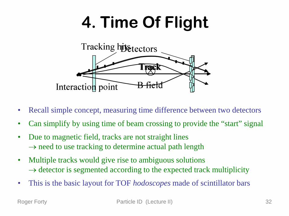
4. Time Of Flight
• Recall simple concept, measuring time difference between two detectors
• Can simplify by using time of beam crossing to provide the “start” signal
• Due to magnetic field, tracks are not straight lines → need to use tracking to determine actual path length
• Multiple tracks would give rise to ambiguous solutions → detector is segmented according to the expected track multiplicity
• This is the basic layout for TOF hodoscopes made of scintillator bars

Roger Forty Particle ID (Lecture II) 33
TOF detectors• Traditional approach to TOF
uses scintillator hodoscopes (see the Scintillator lecture)
• Organic scintillators provide light on a timescale of ~ 100 ps (Inorganic are slower)
• Resolution improves if light yield increased, as can average over the detected photons arrival times
Scintillator hodoscopeReadout with PMs

Roger Forty Particle ID (Lecture II) 34
Resistive Plate Chambers• Fast thin-gap parallel plate detectors were
proposed as alternative to scintillators, for low-cost, large-area TOF systems
• Signal comes from ionization in the gasbetween the plates
High resistivity of the plates required (> 1010 Ωcm) to limit discharge area
• Multigap RPCs use a stack of equally-spaced resistive plates with voltage applied to external surfaces
• Pickup electrodes on external surfaces (resistive plates transparent to fast signal)
Inner plates stop avalanche development → avoid sparks, and high dead time

Roger Forty Particle ID (Lecture II) 35
ALICE MRPC• Made from stacks of 1 mm glass plates,
each with 5 gas gaps of 250 µmGas used is a complicated mixture: C2F4H2 + SF6 + C4H10
• Timing resolution as good as 70 ps has been achieved

Roger Forty Particle ID (Lecture II) 36
TOF performance• The number of standard deviations
separation for a time of flight detector isNσ = |m1
2 – m22| d (TOF)
2 p2 σt c
• Note the similarity to the expression for RICH detectors from before:Nσ = |m1
2 – m22| (RICH)
2 p2 σθ √n2-1
• However, in that case there is an “amplification” factor of 1/√n2-1 which allows RICH detectors to reach high momentum coverage (with a suitable n)
• Combination of TOF with dE/dx can help remove ambiguities:
NA49

Roger Forty Particle ID (Lecture II) 37
TORCH concept• I am currently working on the design of a new concept for Particle ID
for the upgrade of LHCb (planned to follow after ~ 5 years of data taking)
• Uses a large plate of quartz to produce Cherenkov light, like a DIRCBut then identify the particles by measuring the photon arrival timesCombination of TOF and RICH techniques → named TORCH
• Detected position around edge gives photon angle (θx)Angle (θz) out of plane determined using focusing Knowing photontrajectory, the track arrival timecan be calculated Front view Side view

Roger Forty Particle ID (Lecture II) 38
Proposed layout• Optical element added at edges to focus photons onto MCP detectors
It converts the angle of the photon into a position on the detector
Schematic layout Focusing element
Roger Forty Particle ID (Lecture II) 39
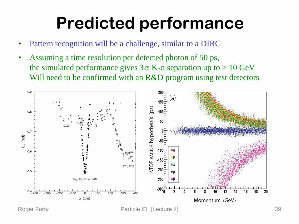
Predicted performance• Pattern recognition will be a challenge, similar to a DIRC
• Assuming a time resolution per detected photon of 50 ps, the simulated performance gives 3σ K-π separation up to > 10 GeV Will need to be confirmed with an R&D program using test detectors

Roger Forty Particle ID (Lecture II) 40
Summary• There is a wide variety of techniques
for identifying charged particles
• Transition radiation is useful in particular for electron identification
• Cherenkov detectors are in widespread use Very powerful, tuning the choice of radiator
• Ionization energy loss is provided by existing tracking detectors but usually gives limited separation, at low p
• Time Of Flight provides excellent performance at low momentumWith the development of faster photon detectors, the range of TOF momentum coverage should increase
• There is still room for new ideas, for the next generation of experimentsMaybe one of your ideas?