PART X PROTOCOL LAYERING - Openloop Technologies · Internetworking With TCP/IP vol 1 -- Part 10 2...
34
PART X PROTOCOL LAYERING Internetworking With TCP/IP vol 1 -- Part 10 1 2005
Transcript of PART X PROTOCOL LAYERING - Openloop Technologies · Internetworking With TCP/IP vol 1 -- Part 10 2...

PART X
PROTOCOL LAYERING
Internetworking With TCP/IP vol 1 -- Part 10 1 2005

Motivation For Layering
� Communication is difficult to understand� Many subproblems
– Hardware failure
– Network congestion
– Packet delay or loss
– Data corruption
– Data duplication or inverted arrivals
Internetworking With TCP/IP vol 1 -- Part 10 2 2005
Solving The Problem
� Divide the problem into pieces� Solve subproblems separately� Combine into integrated whole� Result is layered protocols
Internetworking With TCP/IP vol 1 -- Part 10 3 2005
Protocol Layering
� Separates protocol functionality� Each layer solves one part of the communication problem� Intended primarily for protocol designers� Set of layers is called a protocol stack
Internetworking With TCP/IP vol 1 -- Part 10 4 2005

Concept Of Layering
Layer 1
Layer 2
. . .
Layer n
Sender
Layer 1
Layer 2
. . .
Layer n
Receiver
Network
Internetworking With TCP/IP vol 1 -- Part 10 5 2005

More Realistic Layering
NetworkInterface Layer
InternetProtocol Layer
High-LevelProtocol Layer
IP Module
Protocol 2Protocol 1 Protocol 3
Interface 2Interface 1 Interface 3
Conceptual Layers Software Organization
(a) (b)
Internetworking With TCP/IP vol 1 -- Part 10 6 2005
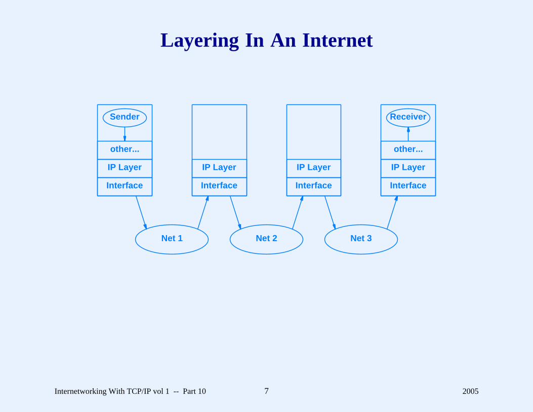
Layering In An Internet
Interface
IP Layer
Interface
IP Layer
Interface
IP Layer
Interface
IP Layer
other...
Sender
other...
Receiver
Net 1 Net 2 Net 3
Internetworking With TCP/IP vol 1 -- Part 10 7 2005

Examples Of Layering
� Two models exist� ISO 7-layer reference model for Open System
Interconnection (OSI)
– Predates TCP/IP
– Does not include an Internet layer
– Prescriptive (designed before protocols)� Internet 5-layer reference model
– Designed for TCP/IP
– Descriptive (designed along with actual protocols)
Internetworking With TCP/IP vol 1 -- Part 10 8 2005
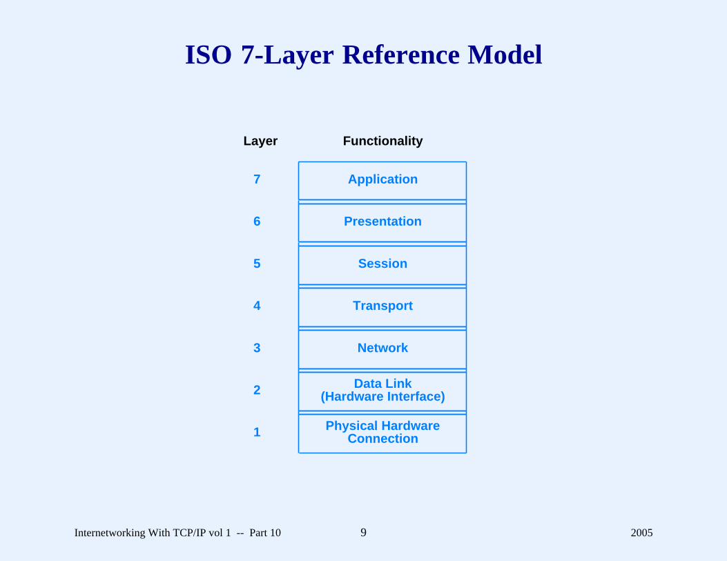
ISO 7-Layer Reference Model
Physical HardwareConnection1
Data Link(Hardware Interface)2
Network3
Transport4
Session5
Presentation6
Application7
FunctionalityLayer
Internetworking With TCP/IP vol 1 -- Part 10 9 2005

TCP/IP 5-Layer Reference Model
Hardware. . . . . . . . . . . . . . . . . . . . . . . . . . . . . . . . . . . . ...
..
..
..
..
..
...................................................
Network Interface
Internet
Transport
Application
Conceptual Layer Objects PassedBetween Layers
Network-Specific Frames
IP Datagrams
Transport Protocol Packets
Messages or Streams
� Only four layers above hardware
Internetworking With TCP/IP vol 1 -- Part 10 10 2005
TCP/IP Layer 1: Physical Hardware
� Defines electrical signals used in communication (e.g.,voltages on wires between two computers)
� Uninteresting except to electrical engineers
Internetworking With TCP/IP vol 1 -- Part 10 11 2005

TCP/IP Layer 2: Network Interface
� Defines communication between computer and networkhardware
� Isolates details of hardware (MAC) addressing� Example protocol: ARP� Code is usually in the operating system
Internetworking With TCP/IP vol 1 -- Part 10 12 2005
TCP/IP Layer 3: Internet
� Protocol is IP� Provides machine to machine communication� Defines best-effort, connectionless datagram delivery service
for the Internet� Code is usually in the operating system
Internetworking With TCP/IP vol 1 -- Part 10 13 2005

TCP/IP Layer 4: Transport
� Provides end-to-end connection from application program toapplication program
� Often handles reliability, flow control� Protocols are TCP and UDP� Code is usually in the operating system
Internetworking With TCP/IP vol 1 -- Part 10 14 2005

TCP/IP Layer 5: Application
� Implemented by application programs� Many application-specific protocols in the Internet� Built on top of transport layer
Internetworking With TCP/IP vol 1 -- Part 10 15 2005

Two Differences Between TCP/IPAnd Other Layered Protocols
� TCP/IP uses end-to-end reliability instead of link-levelreliability
� TCP/IP places the locus of intelligence and decision makingat the edge of the network instead of the core
Internetworking With TCP/IP vol 1 -- Part 10 16 2005

The Layering Principle
Software implementing layer n at the destination receivesexactly the message sent by software implementing layer n atthe source.
Internetworking With TCP/IP vol 1 -- Part 10 17 2005
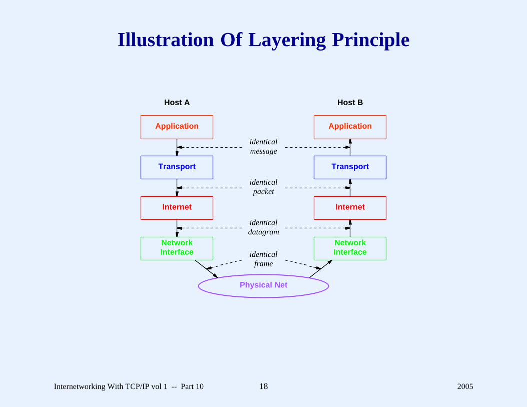
Illustration Of Layering Principle
Application
Transport
Internet
NetworkInterface
NetworkInterface
Internet
Transport
Application
Physical Net
Host A Host B
identicalmessage
identicalpacket
identicaldatagram
identicalframe
Internetworking With TCP/IP vol 1 -- Part 10 18 2005

When A Datagram Traverses The Internet
� All layers involved at
– Original source
– Ultimate destination� Only up through IP layer involved at
– Intermediate routers
Internetworking With TCP/IP vol 1 -- Part 10 19 2005
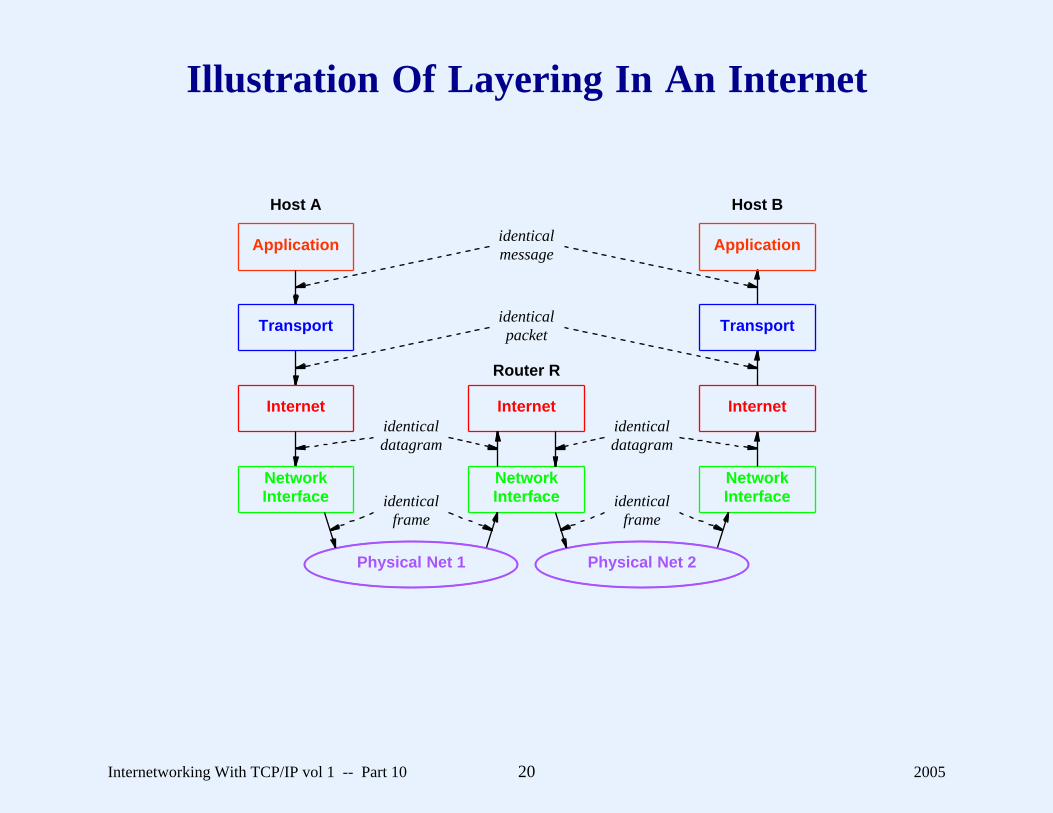
Illustration Of Layering In An Internet
Application
Transport
Internet
NetworkInterface
NetworkInterface
Internet
NetworkInterface
Internet
Transport
Application
Physical Net 1 Physical Net 2
Host A Host B
Router R
identicalmessage
identicalpacket
identicalframe
identicalframe
identicaldatagram
identicaldatagram
Internetworking With TCP/IP vol 1 -- Part 10 20 2005
A Key Definition
� A protocol is classified as end-to-end if the layeringprinciple applies from one end of the Internet to the other
� Examples
– IP is machine-to-machine because layering principleonly applies across one hop
– TCP is end-to-end because layering principle fromoriginal source to ultimate destination
Internetworking With TCP/IP vol 1 -- Part 10 21 2005

Practical Aspect Of Layering
� Multiple protocols at each layer� One protocol used at each layer for given datagram
Internetworking With TCP/IP vol 1 -- Part 10 22 2005

Example Of Two ProtocolsAt Network Interface Layer:
SLIP And PPP� Both used to send IP across
– Serial data circuit
– Dialup connection� Each defines standards for
– Framing (encapsulation)
– Addressing� Incompatible
Internetworking With TCP/IP vol 1 -- Part 10 23 2005

Notion Of Multiple Interfaces And Layering
NetworkInterface
Internet
Transport
Intranet
IP Module
Protocol 2Protocol 1 Protocol 3
Interface 2
Point-To-Point(Intranet)
Interface 1 Interface 3
Conceptual Layer Software Organization
(a) (b)
Internetworking With TCP/IP vol 1 -- Part 10 24 2005

Boundaries In The TCP/IP Layering Model
� High-level protocol address boundary
– Division between software that uses hardware addressesand software that uses IP addresses
� Operating system boundary
– Division between application program running outsidethe operating system and protocol software runninginside the operating system
Internetworking With TCP/IP vol 1 -- Part 10 25 2005

The Consequence Of An Address Boundary
Application programs as well as all protocol software from theInternet layer upward use only IP addresses; the networkinterface layer handles physical addresses.
Internetworking With TCP/IP vol 1 -- Part 10 26 2005

Illustration Of The Two Boundaries
NetworkInterface
Internet
Transport
Application
Hardware. . . . . . . . . . . . . . . . . . . . . . . . . . . . . . . . . . . . . . . ...
..
..
..
..
......................................................
Conceptual Layer Boundary
Only IP addresses used
Physical addresses used
Software outside the operating system
Software inside the operating system
Internetworking With TCP/IP vol 1 -- Part 10 27 2005

Handling Multiple Protocols Per Layer
� Sender places field in header to say which protocol used ateach layer
� Receiver uses field to determine which protocol at next layerreceives the packet
� Known as multiplexing and demultiplexing
Internetworking With TCP/IP vol 1 -- Part 10 28 2005
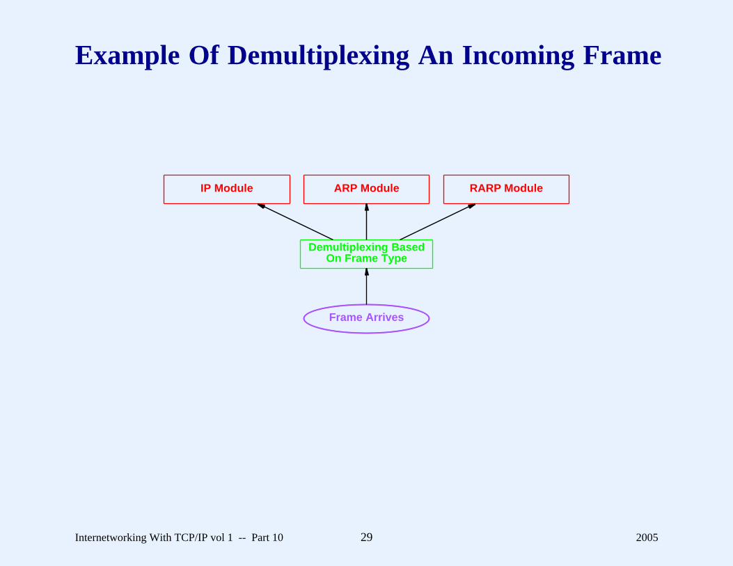
Example Of Demultiplexing An Incoming Frame
Demultiplexing BasedOn Frame Type
ARP ModuleIP Module RARP Module
Frame Arrives
Internetworking With TCP/IP vol 1 -- Part 10 29 2005

Example Of Demultiplexing Performed By IP
ICMP Module UDP Module TCP Module
IP Module
Datagram Arrives
Internetworking With TCP/IP vol 1 -- Part 10 30 2005

Example Of Demultiplexing Performed By TCP
Application 1 Application 2 . . . Application n
TCP Module
Segment Arrives
� TCP is part of operating system� Transfer to application program must cross operating system
boundary
Internetworking With TCP/IP vol 1 -- Part 10 31 2005

Discussion
� What are the key advantages and disadvantages ofmultiplexing / demultiplexing?
� Can you think of an alternative?
Internetworking With TCP/IP vol 1 -- Part 10 32 2005
Summary
� Layering
– Intended for designers
– Helps control complexity in protocol design� TCP/IP uses 5-layer reference model� Conceptually, a router only needs layers 2 and 3, and a host
needs all layers� IP is machine-to-machine protocol� TCP is end-to-end protocol� Demultiplexing used to handle multiple protocols at each
layer
Internetworking With TCP/IP vol 1 -- Part 10 33 2005

Questions?