Part Two Reference Section - narod.ruseaworm.narod.ru/2/ocimf2.pdf · Part Two Reference Section. 1...
147
Vessel Inspection Questionnaire for Bulk Oil, Chemical Tankers and Gas Carriers Second Edition - 2000 Part Two Reference Section
Transcript of Part Two Reference Section - narod.ruseaworm.narod.ru/2/ocimf2.pdf · Part Two Reference Section. 1...

Vessel Inspection Questionnairefor
Bulk Oil, Chemical Tankersand
Gas Carriers
Second Edition - 2000
Part Two
ReferenceSection

1
1. GENERAL INFORMATION
1.2 IMO Number
SOLAS XI/3
Regulation 3Ship Identification number
1 This regulation applies to all passenger ships of 100 gross tonnage and upwards and to all cargo ships of 300 grosstonnage and upwards.*
2 Every ship shall be provided with an identification number which conforms to the IMO ship identification numberscheme adopted by the Organization.
3 The ship’s identification number shall be inserted on the certificates and certified copies thereof issued underregulation I/12 or regulation I/13
4 For ships constructed before 1 January 1996, this regulation shall take effect when a certificate is renewed on or after1 January 1996.
*Refer to the IMO ship identification number scheme adopted by the Organization by Resolution A.600(15)
IMO-Res. A.600 (15)-IMO Ship Identification Number Scheme.
RESOLUTION A.600(15)ADOPTED ON 19 NOVEMBER 1987ANNEXIMO SHIP IDENTIFICATION NUMBER SCHEME
INTRODUCTION
1 The purpose of the scheme is to enhance maritime safety pollution prevention and to facilitate the prevention ofmaritime fraud. It is not intended to prejudice matters of liability, civil law or other commercial considerations in theoperation of a ship. The scheme may be applied by Administrations on a voluntary basis for new and existing ships, undertheir flag, engaged in international voyages. Administrations may also wish to assign the IMO numbers to ships engagedsolely on domestic voyages and to insert the number in the national certificates.
APPLICATION
2 The scheme applies to seagoing ships of 100 gross tonnage and above, with the exception of the following:
- Vessels solely engaged in fishing;- ships without mechanical means of propulsion;- pleasure yachts;- ships engaged on special service */1;- hopper barges;- hydrofoils, hovercraft;- floating docks and structures classified in a similar manner;

2
- ships of war and troop ships; and- wooden ships in general
______*/1 For example, lightships, floating radio stations, search and rescue vessels.
ASSIGNMENT OF IMO NUMBER
3 The IMO number is a Lloyd's Register (LR) number, allocated at the time of build or when a ship is first included inthe register, with the prefix IMO (e.g. IMO 8712345). Administrations which have decided to implement the scheme areinvited to assign all appropriate ships flying their flags, or cause them to be assigned, the IMO numbers and to insert them onships' certificates.
4 For new ships, the assignment of the IMO number should be made when the ship is registered. For existing ships,the assignment of the IMO number should be made at an early convenient date, such as when the renewal survey iscompleted or new certificates are issued.
5 Administrations implementing the scheme are invited to inform the Organisation accordingly, for circulation toother Governments.
6 Official publications and other information from LR and Lloyd's Maritime Information Services (MIS) are sourcesfor referencing the identification number. If the particulars of a ship do not correspond to those shown in the Register ofShips and its supplement because, for example, the ship had changed its name, or the port State control officer had doubts asto whether the numbers given on the certificates were genuine, further clarification may be sought from Lloyd's Register, theIMO Secretariat or the flag state.
CERTIFICATES ON WHICH THE IMO NUMBER IS TO BE INSERTED
7 The IMO number should be inserted on a ship's Certificate of Registry which includes the particulars identifying theship, and on all certificates issued under IMO conventions when and where appropriate. It is recommended that the IMOnumber also be inserted in other certificates, Suez and Panama tonnage certificates, when and where appropriate. The IMOnumber should preferably be included in the box headed "Distinctive number or letters" in addition to the call sign.
HOW TO OBTAIN THE IMO NUMBER
8 The following information indicates how IMO numbers can be obtained for both new and existing ships. New ships(on order and under Construction)
9 The IMO number can be obtained by one of the following methods:
9.1 Enquiries addressed to the Maritime Information Publishing Group of LR, by telex or facsimile */2. In making suchenquiry the following particulars , if possible, should be presented:
- Shipyard and yard number or hull number- Ship name (if known)- GT/DWT- Keel-laid date- Owner, operator/manager and flag- Basic ship-type */3- Name and address of enquirer.
_______*/2 Telex 888379 Telefax (Fax) No. 01-4884796(GpIII)*/3 Basic ship-types used by LR include:
Passenger Ferry General cargoSpecialised cargo Cellular container Ro-ro cargoBulk Specialised bulk Ore cargoGas tanker Gas carrier TankerSpecialised tanker Tug Factory

3
Dredger Sand carrier ORSV/Supply
or any combination of these types.
Based on the above information, LR will provide the necessary IMO number free of charge. If there are no data in the LRnew construction file on the ship concerning which the enquiry is made, a new record on that ship will be created and the LRnumber will be assigned.
9.2 On-line access to the new construction file through SEADATA (IMO has access to this system).
9.3 Application through LMIS which will provide a service of regular listings of the order book with selected data items,produced for a client's specification.
EXISTING SHIPS
10 The following methods are available for obtaining the IMO number:
10.1 The Register of Ships and the 11 cumulative monthly supplements to it published by Lloyd's register. It is publishedin 3 volumes and lists details of over 76,000 merchant ships.
10.2 The weekly list of alterations to the Register of Ships (non-cumulative) produced by Lloyd's Register.
10.3 On-line access to the Lloyd's Register Ship Particulars File through the SEADATA system (IMO has access to thesystem).
11 For existing ships, LR is prepared to answer ad hoc requests free of charge up to a reasonable point of acceptability.
12 Any information on charges for services mentioned in paragraphs 9 and 10 may be obtained from Lloyd's Register ofShipping.
ENQUIRY TO THE IMO SECRETARIAT
13 The IMO number may be obtained free of charge from the IMO Secretariat */4 which has access to the SEADATAsystem. In making such an enquiry to the IMO Secretariat, information on particulars of the ship (as in paragraph 9.1)should be provided in writing.
1.31 Port of last port State control inspectionSOLAS XI/4, IMO Res. A787(19)
SOLAS XI Regulation 4Port State control on operational requirements
1 A ship when in a port of another Contracting Government is subject to control by officers duly authorized by suchGovernment concerning operational requirements in respect of the safety of ships, when there are clear grounds forbelieving that the master and crew are not familiar with essential shipboard procedures relating to the safety ofships.
2 In the circumstances defined in paragraph 1 of this regulation, the Contracting Government carrying out the controlshall take such steps as will ensure that the ship shall not sail until the situation has been brought to order inaccordance with the requirements of the present Convention.
3 Procedures relating to the port State control prescribed in regulation I/19 shall apply to this regulation.4 Nothing in the present regulation shall be construed to limit the rights and obligations of a Contracting Government
carrying out control over operational requirements specifically provided for in the regulations.
IMO Res. A787(19
Refer to document

4
2. CERTIFICATION ANDDOCUMENTATION
2.2 Are all statutory certificates, where applicable, valid?IMO MSC/Circ. 70421 September 1995
LISTING OF CERTIFICATES AND DOCUMENTS REQUIREDTO BE CARRIED ON BOARD SHIPS
1 The Facilitation Committee, at its nineteenth session, developed a list of certificates and documents required to becarried on board ships together with a brief description of the purpose of the certificates and other relevant documents. Thiswork was carried out in connection with the provisions of section 2 of the annex to the FAL Convention concerningformalities required of shipowners by public authorities on the arrival, stay and departure of ships. The FacilitationCommittee considered that these provisions should not be read as precluding a requirement for the presentation for inspectionby the appropriate authorities of certificates and other documents carried by the ship pertaining to its registry, measurement,safety, manning, classification and other related matters.
2 The Marine Environment Protection Committee, at its thirtieth session, considered the listing of certificates anddocuments required to be carried on board ships to be complete, useful and informative and expressed its appreciation to theFacilitation Committee for the work carried out.
3 The Maritime Safety Committee, at its fifty-ninth and sixtieth sessions, considered the listing and made a number ofamendments pertaining to its scope of work. The listing, as approved by the Maritime Safety Committee at its sixtieth sessionon the recommendation of the joint MSC/MEPC working group on survey and certification and the Facilitation Committee atits twenty-first session, was circulated under symbol FAL.2/Circ.35, MEPC/Circ.257 and MSC/Circ.593.
4 Due to amendments to the SOLAS Convention 1974, as amended, which entered into force on 1 January 1994 and 1January 1996, respectively, and the MARPOL Convention 73/78, as amended, which entered into force on 28 February 1994,the listing had to be revised with respect to sections 2, 3 and 7. The revised listing is set out at annex.
5 Administrations are invited to note the information provided in the annex and take action as appropriate.
ANNEX

5
CERTIFICATES AND DOCUMENTS REQUIRED TO BE CARRIED ON BOARD SHIPS(Note: All certificates to be carried on board must be originals)
1 All shipsInternational Tonnage Certificate (1969)An International Tonnage Certificate (1969) shall be issued to every ship, the grossand net tonnage of which have been determined in accordance with the Convention.
TonnageConventionarticle 7
International Load Line CertificateAn International Load Line Certificate shall be issued under the provisions of theInternational Convention on Load Lines, 1966, to every ship which has beensurveyed and marked in accordance with the Convention.
LLConvention,article 16
An International Load Line Exemption Certificate shall be issued to any ship towhich an exemption has been granted under and in accordance with article 6 of theLoad Line Convention.
LLConvention,article 6
Intact stability bookletAll ships of 24 metres and over shall be inclined on completion and the elements oftheir stability determined. The master shall be supplied with a Stability Bookletcontaining such information as is necessary to enable him, by rapid and simpleprocedures, to obtain accurate guidance as to the ship under varying conditions ofloading.
SOLAS 1974,regulation II-1/22
Minimum safe manning documentEvery ship to which chapter I of the Convention applies shall be provided with anappropriate safe manning document or equivalent issued by the Administration asevidence of the minimum safe manning.
SOLAS 1974(1989amendments)regulationV/13(b)
Certificates for masters, officers or ratingsCertificates for masters, officers or ratings shall be issued to those candidates who,to the satisfaction of the Administration, meet the requirements for service, age,medical fitness, training, qualifications and examinations in accordance with theprovisions of the Annex to the Convention on Standards of Training, Certificationand Watchkeeping for Seafarers, 1978. Certificates for masters and officers, issuedin compliance with this article, shall be endorsed by the issuing Administration inthe form prescribed in regulation 1/2 of the Annex.
STCW 1978,article VI
International Oil Pollution Prevention CertificateAn international oil pollution prevention certificate shall be issued after survey inaccordance with regulation 4 of Annex I of MARPOL 73/78, to any oil tanker of150 grt and above and any other ship of 400 grt and above which are engaged invoyages to ports or offshore terminals under the jurisdiction of other Parties toMARPOL 73/78. The certificate is supplemented with a Record of Construction andEquipment for Ships other than Oil Tankers (Form A) Record of Construction andEquipment for Oil Tankers (Form B), as appropriate.
MARPOL 73/78,Annex I,regulation 5
Oil Record BookEvery oil tanker of 150 grt and above and every ship of 400 grt and above otherthan an oil tanker shall be provided with an Oil Record Book, Part I (Machineryspace operations). Every oil tanker of 150 grt and above shall also be provided withan Oil Record Book, Part II (Cargo/ballast operations).
MARPOL 73/78,Annex 1regulation 20
6
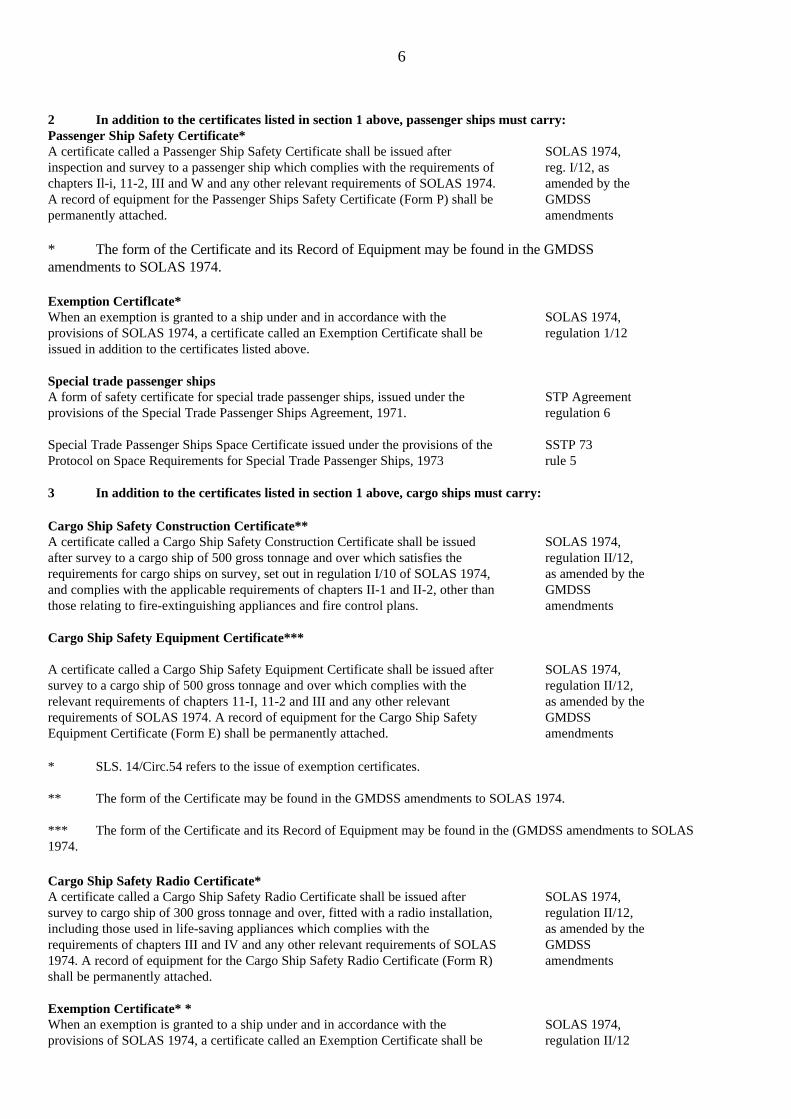
2 In addition to the certificates listed in section 1 above, passenger ships must carry:Passenger Ship Safety Certificate*A certificate called a Passenger Ship Safety Certificate shall be issued afterinspection and survey to a passenger ship which complies with the requirements ofchapters Il-i, 11-2, III and W and any other relevant requirements of SOLAS 1974.A record of equipment for the Passenger Ships Safety Certificate (Form P) shall bepermanently attached.
SOLAS 1974,reg. I/12, asamended by theGMDSSamendments
* The form of the Certificate and its Record of Equipment may be found in the GMDSSamendments to SOLAS 1974.
Exemption Certiflcate*When an exemption is granted to a ship under and in accordance with theprovisions of SOLAS 1974, a certificate called an Exemption Certificate shall beissued in addition to the certificates listed above.
SOLAS 1974,regulation 1/12
Special trade passenger shipsA form of safety certificate for special trade passenger ships, issued under theprovisions of the Special Trade Passenger Ships Agreement, 1971.
STP Agreementregulation 6
Special Trade Passenger Ships Space Certificate issued under the provisions of theProtocol on Space Requirements for Special Trade Passenger Ships, 1973
SSTP 73rule 5
3 In addition to the certificates listed in section 1 above, cargo ships must carry:
Cargo Ship Safety Construction Certificate**A certificate called a Cargo Ship Safety Construction Certificate shall be issuedafter survey to a cargo ship of 500 gross tonnage and over which satisfies therequirements for cargo ships on survey, set out in regulation I/10 of SOLAS 1974,and complies with the applicable requirements of chapters II-1 and II-2, other thanthose relating to fire-extinguishing appliances and fire control plans.
SOLAS 1974,regulation II/12,as amended by theGMDSSamendments
Cargo Ship Safety Equipment Certificate***
A certificate called a Cargo Ship Safety Equipment Certificate shall be issued aftersurvey to a cargo ship of 500 gross tonnage and over which complies with therelevant requirements of chapters 11-I, 11-2 and III and any other relevantrequirements of SOLAS 1974. A record of equipment for the Cargo Ship SafetyEquipment Certificate (Form E) shall be permanently attached.
SOLAS 1974,regulation II/12,as amended by theGMDSSamendments
* SLS. 14/Circ.54 refers to the issue of exemption certificates.
** The form of the Certificate may be found in the GMDSS amendments to SOLAS 1974.
*** The form of the Certificate and its Record of Equipment may be found in the (GMDSS amendments to SOLAS1974.
Cargo Ship Safety Radio Certificate*A certificate called a Cargo Ship Safety Radio Certificate shall be issued aftersurvey to cargo ship of 300 gross tonnage and over, fitted with a radio installation,including those used in life-saving appliances which complies with therequirements of chapters III and IV and any other relevant requirements of SOLAS1974. A record of equipment for the Cargo Ship Safety Radio Certificate (Form R)shall be permanently attached.
SOLAS 1974,regulation II/12,as amended by theGMDSSamendments
Exemption Certificate* *When an exemption is granted to a ship under and in accordance with theprovisions of SOLAS 1974, a certificate called an Exemption Certificate shall be
SOLAS 1974,regulation II/12

7
issued in addition to the certificates listed above.
Document of compliance with the special requirements for ships carryingdangerous goodsAn appropriate document as evidence of compliance with the construction andequipment requirements of that regulation.
SOLAS 1974,regulation II-2/54.3
Dangerous goods manifest or stowage planEach ship carrying dangerous goods shall have a special list or manifest settingforth, in accordance with the classification set out in regulation VI1/2, thedangerous goods on board and the location thereof. A detailed stowage plan whichidentifies by class and sets out the location of all dangerous goods on board, may beused in place of such a special list or manifest. A copy of one of these documentsshall be made available before departure to the person or organization designated bythe port State authority.
SOLAS 1974,regulationVII/5(5)MARPOL 73/78Annex III,regulation 4
Document of authorization for the carriage of grainA document of authorization shall be issued for every ship loaded in accordancewith the regulations of the International Code for the Safe Carriage of Grain inBulk either by the Administration or an organization recognized by it or by aContracting Government on behalf of the Administration. The document shallaccompany or be incorporated into the grain loading manual provided to enable themaster to meet the stability requirements of the Code.
SOLAS 1974,regulation V1/9InternationalCode for the SafeCarriage of Grainin Bulk,section 3
* The form of the Certificate and its Record of Equipment may be found in the GMDSS amendments to SOLAS 1974.
** SLS. 14/Circ.54 refers to the issue of exemption certificates.
Certificate of insurance or other financial security in respect of civil liabilityfor oil pollution damageA certificate attesting that insurance or other financial security is in force shall beissued to each ship carrying more than 2,000 tons of oil in bulk as cargo. It shall beissued or certified by the appropriate authority of the State of the ship's registry afterdetermining that the requirements of article VII, paragraph 1, of the CLCConvention have been complied with.
CLC 69,article VII
Enhanced survey report file*A survey report file and supporting documents complying with paragraphs 6.2 and6.3 of annex A and annex B of resolution A.744(18) - Guidelines on the enhancedprogramme of inspections during surveys of bulk carriers and oil tankers.
MARPOL 73/78,Annex I,regulation 1 13GSOLAS 1974,regulation X1/2
4 In addition to the certificates listed in sections 1 and 3 above, where appropriate, any shipcarrying noxious liquid chemical substances in bulk shall carry:
International Pollution Prevention Certificate for the Carriage Noxious LiquidSubstances in Bulk. (NLS certificate)An international pollution prevention certificate for the carriage of noxious liquidsubstances in bulk (LS certificate) shall be issued, after survey in accordance withthe provisions of regulation 10 of Annex II of MARPOL 73/78, to any ship carryingnoxious liquid substances in bulk and which is engaged in voyages to ports orterminals under the jurisdiction of other Parties to MARPOL 73/78. In respect ofchemical tankers, the Certificate of Fitness for the Carriage of DangerousChemicals in Bulk and the International Certificate of Fitness for the Carriage ofDangerous Chemicals in Bulk, issued under the provisions of the Bulk ChemicalCode and International Bulk Chemical Code, respectively, shall have the same forceand receive the same recognition as the NLS certificate.
MARPOL73/78,Annex II,regulations 12 and12a

8
* Subject to entry into force of the amendments adopted by the 1994 SOLAS Conference on 24 May 1994.
Cargo record bookEvery ship to which Annex II of MARPOL 73/78 applies, shall be provided witha Cargo Record Book, whether as part of the ship's official log book orotherwise, in the form specified in appendix IV to the Annex.
MARPOL73/78,Annex II,regulation 9
5 In addition to the certificates listed in sections 1 and 3 above, where applicable, any chemicaltanker shall carry:
Certificate of Fitness for the Carriage of Dangerous Chemicals in bulkA certificate called a Certificate of Fitness for the Carriage of DangerousChemicals in Bulk, the model form of which is set out in the appendix to theBulk Chemical Code, should be issued after an initial or periodical survey to achemical tanker engaged in international voyages which complies with the relevant requirements of theCode.
BCH CodeSection 1.6
Note: The Code is mandatory under Annex II of MARPOL 73/78 for chemical tankers constructedbefore 1 July 1986.
Or
International Certificate of Fitness for the Carriage of Dangerous Chemicals in BulkA certificate called an International Certificate of Fitness for the Carriage ofDangerous Chemicals in Bulk, the model form of which is set out in theappendix to the International Bulk Chemical Code, should be issued after aninitial or periodical survey to a chemical tanker engaged in international voyageswhich complies with the relevant requirements of the Code.
BCH CodeSection 1.5
Note: The Code is mandatory under both chapter VII of SOLAS 1974 and Annex II of MARPOL 73/78for chemical tankers constructed on or after 1 July 1986.
6 In addition to the certificates listed in sections 1 and 3 above, where applicable, any gascarrier shall carry:
Certificate of Fitness for the Carriage of Liquefied Gases in BulkA certificate called a Certificate of Fitness for the Carriage of Liquefied Gases inBulk, the model form of which is set out in the appendix to the Gas CarrierCode, should be issued after an initial or periodical survey to a gas carrier whichcomplies with the relevant requirements of the Code.
GC Codesection 1.6
or
International Certificate of Fitness for the Carriage of Liquefied Gases inBulkA certificate called an International Certificate of Fitness for the Carriage ofLiquefied Gases in Bulk, the model form of which is set out in the appendix tothe International Gas Carrier Code, should be issued after an initial or periodicalsurvey to a gas carrier which complies with the relevant requirements of theCode.
GC Codesection 1.5
Note: The Code is mandatory under chapter VII of SOLAS 1974 for gas carriers constructed on or after1 July 1986.
7 In addition to the certificates listed in sections 1 and 3 above, where applicable, high speedcrafts must carry:*

9
High Speed craft safety certificateA certificate called a High Speed Craft Safety Certificate should be issued aftercompletion of an initial or renewal survey to a craft which complies with therequirements of the High Speed Certificate (HSC) Code in its entirety.
SOLAS 1974,regulation X/3;HSC Codeparagraph 1.8
Permit to Operate High Speed CraftA certificate called a Permit to Operate High Speed Craft should be issued to acraft which complies with the requirements set out in paragraphs 1.2.2 to 1.2.7and 1.8 of the HSC Code.
HSC Codeparagraph 1.9
* Subject to entry into force of the amendments adopted by the 1994 SOLAS Conference on 24 May1994.
Miscellaneous other certificates
Special purpose ships
Special purpose ships safety certificateA certificate may be issued after survey in accordance with the provisions ofparagraph 1.6 of the Code for Special Purpose Ships. The duration and validityof the certificate should be governed by the respective provisions for cargo shipsin SOLAS 1974. If a certificate is issued for a special purpose ship of less than500 tons gross tonnage, this certificate should indicate to what extent relaxationsin accordance with 1.2 were accepted.
A.534(13),
Additional Certificate for Offshore Supply VesselsWhen carrying such cargoes, offshore supply vessels should carry a Certificate ofFitness under the "Guidelines for the Transport and Handling of LimitedAmounts of Hazardous and Noxious and Liquid Substances in Bulk on OffshoreSupport Vessels"
A. 673(16),MARPOL 73/78,Annex II,regulation 13 (4)
If an offshore supply vessel carries only noxious liquid substances, a suitablyendorsed International Pollution Prevention Certificate for the Carriage ofNoxious Liquid Substances in Bulk may be issued instead of the aboveCertificate of Fitness.
Diving systems
Diving system safety certificateA certificate should be issued either by the Administration or any person ororganization duly authorized by it after survey or inspection to a diving systemwhich complies with the requirements of the Code of Safety for Diving Systems.In every case, the Administration should assume full responsibility for thecertificate.
A.536(13), section1.6
Dynamically supported craft
Construction and Equipment CertificateTo be issued after survey carried out in accordance with paragraph 1.5.1(a) ofthe Code of Safety for Dynamically Supported Craft.
A.373(X),section1.6
Mobile Offshore Drilling Units
Safety certificateTo be issued after survey carried out in accordance with the provisions of theCode for the Construction and Equipment of Mobile Offshore Drilling Units,1979, or, for units constructed on or after 1 May 1991, the Code for theConstruction and Equipment of Mobile Offshore Drilling Units, 1989.
A.414(XI),section 1.6A.649(16)section 1.6

10
Noise levels
Noise Survey ReportA noise survey report should be made for each ship in accordance with the Codeon Noise Levels on Board Ships.
A468(XII),section 4.3
Safety Equipment CertificateSOLAS 1/8 1/12 (a)(iii)(a) The life-saving appliances, except a radiotelegraph installation in a motor lifeboat or a portable radio apparatus forsurvival craft, the echo-sounding device, the gyro compass, the fire extinguishing appliances and the inert gas system ofcargo ships to which chapters II-1, II-2, III and V apply, shall be subject to initial and subsequent surveys as prescribed forpassenger ships in regulation 7 of this chapter with the substitution of 24 months for 12 months in subparagraph (a)(ii) ofthat regulation. The fire control plans in new ships and the pilot ladders, mechanical pilot hoists, lights, shapes and meansof making sound signals carried by new and existing ships shall be included in the surveys for the purpose of ensuring thatthey comply fully with the requirements of the present regulations and, where applicable, the International Regulations forPreventing Collisions in sea in force.
(b) Intermediate surveys shall be made for tankers of ten years of age and over, within three months before or after theanniversary date of the Cargo Ship Safety Equipment Certificate, to ensure that equipment specified in paragraph (a) of thisregulation has been maintained in accordance with regulation 11 of this chapter and that it is in good working condition.Such intermediate surveys shall be endorsed on the Cargo Ship Safety Equipment Certificate issued in accordance withregulation 12(a)(iii) of this chapter.
(Reference is made to the Record of approved cargo ship safety equipment (SLS.14/Circ.1).(Reference is made to the Guidelines on Mandatory Annual Surveys, Unscheduled Inspections of all Cargo Ships as well asIntermediate Surveys on Tankers of Ten Years of Age and Over, under the Protocol of 1978 relating to the InternationalConvention for the Safety of Life At Sea, 1974 (resolution A.413(XI) as amended by resolution A.465(XII).
SOLAS 1/12 (a)(iii)(iii) A certificate called a Cargo Ship Safety Equipment Certificate shall be issued after inspection to a cargo ship whichcomplies with the relevant requirements of chapters II-1, II-2 and III and any other relevant requirements of the presentregulations. (Reference is made to the circular concerning issue of supplements and attachments (PSLS.2/Circ.1).
Safety Radio CertificateSOLAS 1/9 1/12 (a)(iv)The radio installations of cargo ships including those used in lifesaving appliances to which chapters III and IV apply shallbe subject to initial and subsequent surveys as provided for passenger ships in regulation 7 of this chapter.
SOLAS I/12 (a)(iv)
A certificate called a Cargo Ship Safety Radiotelegraphy Certificate shall be issued to a cargo ship which complies with therequirements of chapter IV and any other relevant requirements of the present regulations.
Safety Construction Certificate (1)SOLAS I/10. 1/12 (a)(ii)
SOLAS I Regulation 10(a) The hull, machinery and equipment (other than items in respect of which Cargo Ship Safety Equipment Certificatesor Cargo Ship Safety Radiotelegraphy Certificates are issued) of a cargo ship shall be surveyed on completion and thereafterin such a manner as the Administration may consider necessary in order to ensure that their condition is in all respectssatisfactory and at the following intervals:
(i) At intervals specified by the Administration but not exceeding five years (Periodical surveys);(ii) In addition to such periodical surveys a tanker of ten years of age and over shall undergo a minimum of one
intermediate survey during the period of validity of its Cargo Ship Safety Construction Certificate. In caseswhere only one such intermediate survey is carried out in any one certificate validity period, it shall be heldnot before six months prior to, nor later than six months after, the half-way date of the certificate's period ofvalidity.

11
(b) The initial and periodical survey shall be such as to ensure that the arrangements, material and scantlings of thestructure, boilers and other pressure vessels, their appurtenances, main and auxiliary machinery including steering gear andassociated control systems, electrical installation and other equipment are in all respects satisfactory for the service forwhich the ship is intended. Such surveys shall, in the case of tankers, also include inspection of the outside of the ship'sbottom, pump-rooms, cargo and bunker piping systems, vent piping, pressure vacuum valves and flame screens.
(c) The intermediate survey of tankers of ten years of age and over shall include inspection of steering gear equipmentand associated control systems, pump-rooms, cargo and bunker piping systems on deck and in pump-rooms, vent piping,pressure vacuum valves and flame screens, the electrical installations in dangerous zones, and the outside of the ship'sbottom. In addition to the visual inspection of the electrical installation, the insulation resistance of the electrical equipmentin dangerous zones is to be tested. If, upon examination, there should be any doubt as to the condition of the piping, extrameasures, such as pressure tests and thickness determination, shall be taken as necessary. Such intermediate surveys shallbe endorsed on the Cargo Ship Safety Construction Certificate issued in accordance with regulation 12(a)(ii) of this chapter.
(d) A survey, either general or partial according to the circumstances, shall be made when required after aninvestigation prescribed in regulation 11 of this chapter, or whenever any important repairs or renewals are made. Thesurvey shall be such as to ensure that the necessary repairs or renewals have been effectively made, that the material andworkmanship of such repairs or renewals are in all respects satisfactory, and that the ship is fit to proceed to sea withoutdanger to the ship or persons on board.(Reference is made to the Guidelines on Mandatory Annual Surveys, Unscheduled Inspections of all Cargo Ships as well asIntermediate Surveys on Tankers of Ten Years of Age and Over, under the Protocol of 1978 relating to the InternationalConvention for the Safety of Life At Sea, 1974 (resolution A.413(XI) as amended by resolution A.465(XII). (Reference ismade to the circular concerning inspection of the outside of the ship's bottom (PSLS.2/Circ.5).
SOLAS 1/12 (a)(ii)A certificate called a Cargo Ship Safety Construction Certificate shall be issued after survey to a cargo ship which satisfiesthe requirements for cargo ships on survey set out in regulation 10 of this chapter and complies with the applicablerequirements of chapters II-1, and II-2 other than those relating to fire-extinguishing appliances and control plans.
Loadline CertificateLOADLINE Art 16-19 incl.
Article 16Issue of Certificates(1) An International Load Line Certificate (1966) shall be issued to every ship which has been surveyed and marked inaccordance with the present Convention.
(2) An International Load Line Exemption Certificate shall be issued to any ship to which an exemption has beengranted under and in accordance with paragraph (2) or (4) of Article 6.
(3) Such certificates shall be issued by the Administration or by any person or organisation duly authorised by it. Inevery case, the Administration assumes full responsibility for the certificate.
(4) Notwithstanding any other provision of the Present Convention, any international load line certificate which iscurrent when the present Convention comes into force in respect of the Government of the State whose flag the ship isflying shall remain valid for two years or until it expires, whichever is earlier. After that time an International Load LineCertificate (1966) shall be required.
Article 17Issue of Certificate by another Government(1) A Contracting Government may, at the request of another Contracting Government, cause a ship to be surveyed and,if satisfied that the provisions of the present Convention are complied with, shall issue or authorise the issue of anInternational Load Line Certificate (1966) to the ship in accordance with the present Convention.
(2) A copy of the certificate, a copy of the survey report used for computing the freeboard, and a copy of thecomputations shall be transmitted as early as possible to the requesting Government.

12
(3) A certificate so issued must contain a statement to the effect that it has been issued at the request of the Governmentof the state whose flag the ship is or will be flying and it shall have the same force and receive the same recognition as acertificate issued under Article 16.
(4) No International Load Line Certificate (1966) shall be issued to a ship which is flying the flag of a State theGovernment of which is not a Contracting Government.
Article 18Form of Certificates(1) The certificates shall be drawn up in the official language or languages of the issuing country. If the language usedis neither English nor French, the text shall include a translation into one of these languages.
(2) The form of the certificates shall be that of the models given in Annex III. The arrangement of the printed part ofeach model certificate shall be exactly reproduced in any certificates issued, and in any certified copies thereof.
Article 19Duration of Certificates(1) An International Load Line Certificate (1966) shall be issued for a period specified by the Administration, whichshall not exceed five years from the date of issue.
(2) If, after the periodical survey referred to in paragraph (1) (b) of Article 14, a new certificate cannot be issued to theship before the expiry of the certificate originally issued, the person or organisation carrying out the survey may extend thevalidity of the original certificate for a period which shall not exceed five months. This extension shall be endorsed on thecertificate, and shall be granted only where there have been no alterations in the structure, equipment, arrangements,material or scantlings which affect the ship's freeboard.
(3) An International Load Line Certificate (1966) shall be cancelled by the Administration if any of the followingcircumstances exist:
(a) Material alterations have taken place in the hull or superstructures of the ship such as would necessitate theassignment of an increased freeboard;
(b) The fittings and appliances mentioned in sub-paragraph (c) of paragraph (1) of Article 14 are notmaintained in an effective condition.
(c) The certificate is not endorsed to show that the ship has been inspected as provided in sub-paragraph (c) ofparagraph (1) of Article 14;
(d) The structural strength of the ship is lowered to such an extent that the ship is unsafe.
(4) (a)The duration of an International Load Line Exemption Certificate issued to a ship exempted under paragraph (4)of Article 6 shall be limited to the single voyage for which it is issued.
(5) A certificate issued to a ship by an Administration shall cease to be valid upon the transfer of such a ship of anotherState.
IOPP CertificateMARPOL 73/78 Annex I 5(1)Issue of Certificate(1) An international Oil Pollution Prevention Certificate shall be issued, after survey in accordance with the provisionsof regulation 4 of this Annex, to any oil tanker of 150 tonnes gross tonnage and above and any other ships of 400 tonnesgross tonnage and above which are engaged in voyages to ports or offshore terminals under the jurisdiction of other Partiesto the Convention. In the case of existing ships this requirement shall apply twelve months after the date of entry into forceof the present Convention.
Cert of Insurance in Respect of Civil Liability for Oil Pollution (CLC)(2)
LIABILITY (VII)(2)A certificate attesting that insurance or other financial security is in force in accordance with the provisions of thisConvention shall be issued to each ship. It shall be issued or certified by the appropriate authority of the state of the ship'sregistry after determining that the requirements of paragraph 1 of this Article have been complied with. This certificateshall be in the form of the annexed model and shall contain the following particulars:
1 name of ship and port of registration;2 name and principle place of business of owner;

13
3 type of security;4 name and principle place of business of insurer or other person giving security and, where appropriate, place of
business where the insurance or security is established;5 period of validity of certificate which shall not be longer than the period of validity of the insurance or other
security.
Paragraph 1The owner of a ship registered in a Contracting State and carrying more than 2,000 tonnes of oil in bulk as cargo shall berequired to maintain insurance or other financial security, such as the guarantee of a bank or a certificate delivered by aninternational compensation fund, in the sums fixed by applying the limits of liability prescribed in Article V, paragraph 1 tocover his liability for pollution damage under this Convention.
USCG 33 CFR.138.2(F)(f) Certificate means a Certificate of Financial Responsibility (Water Pollution), Form CG-5358-10 issued by the USCoast Guard under this part.
USCG 33 CFR 130.3(A)(a) No vessel shall use any port or place in, or the navigable waters of, the United States, unless that vessel has aCertificate covering that vessel and its operator.(Refer to the current version of USCG 33 CFR and USCG 46 CFR.). (Refer to USCG 33 CFR Parts 154, 155, 156.)
USCG Letter of Compliance or date of last TVEUSCG 46 CFR 2.01-6. SOLAS 1/19
USCG 46 CFR 2.01-6Certificate Issued to Foreign Vessels
(a) Issuance of certificates. Upon Completion of an examination of a foreign vessel, one or more of the followingcertificates is issued by the officer in Charge, Marine Inspection:(1) CG-4504-Control Verification for Foreign Vessel-issued to a foreign vessel that is registered in a country which issignatory to the International Convention for the Safety of Life at Sea, 1974.(2) CG-2832A--Letter of Compliance-issued to a foreign vessel that is suitable for carriage of hazardous cargoes in bulkas defined in 46 Code of Federal Regulations, subchapter 0 and is in compliance with Tankship Cargo Venting andHandling Systems and Minimum Pollution Prevention Regulations and Transfer Procedures (33CFR parts 155, 156, 157and 159), and Navigation Safety Inspection Regulations (33 CFR part 164).
(3) CG-840S-1--Tank Vessel Examination Letter-issued to a foreign vessel that is suitable for carriage of cargoes asdefined in 46 Code of Federal Regulations, subchapter D and is in compliance with Tankship Cargo Venting and HandlingSystems and Minimum Safety Standards (SOLAS 74--46 CFR part 35), Pollution Prevention Regulations and TransferProcedures (33 CFR parts 155, 156, 157 and 159), and Navigation Safety Regulations (33 CFR part 164).(4) Foreign vessels of countries which are non-signatory to the International Convention for the Safety of Life at Sea,1974, are issued a Temporary Certificate of Inspection (CG-841) as described in 2.01-5.
(b)Description of Certificates.(1) CG-4504-control Verification for Foreign Vessels-describes the vessel, type of certificate required by theInternational Convention for the Safety of Life at Sea, 1974, country issued by, and its expiration date. The period ofvalidity of a control verification for foreign vessel is stated on the certificate.(2) CG-2832A-Letter of Compliance-describe the vessel and the period for which the letter is valid.(3) CG-840S-1-Tank Vessel Examination Letter-describe the vessel and if there are any deficiencies as to applicableregulations at the time the vessel was examined. If there are deficiencies they are listed in an attachment to this letter (CG-840S-2). The Tank Vessel Examination Letter is valid for a period of 1 year from the date the examination is completed.(4) Temporary Certificate of Inspection (CG-854) and Certificate of Inspection (CG-841) are amended as provided forin 2.01-5(c).[CGD 77-014, 44 FR 5316, Jan.25, 1979, as amended by CGD 90-008, 55 FR 30659, July 26, 1990]
SOLAS 1 Regulation 19Control

14
(a) Every ship when in a port of another Party is subject to control by officers duly authorised by such Government in so faras this control is directed towards verifying that the certificates issued under regulation 12 or regulation 13 of this chapterare valid.
(b) Such certificates, if valid, shall be accepted unless there are clear grounds for believing that the condition of the ship orof its equipment does not correspond substantially with the particulars of any of the certificates or that the ship and itsequipment are not in compliance with the provisions of regulation 11(a) and (b) of this chapter.
(c) In the circumstances given in paragraph (b) of this regulation or where a certificate has expired or ceased to be valid, theofficer carrying out the control shall take steps to ensure that the ship shall not sail until it can proceed to sea or leave portfor the purpose of proceeding to the appropriate repair yard without danger to the ship or persons on board.
(d) In the event of this control giving rise to an intervention of any kind, the officer carrying out the control shall forthwithinform, in writing, the Consul or, in his absence, the nearest diplomatic representative of the State whose flag the ship isentitled to fly of all the circumstances in which intervention was deemed necessary. In addition, nominated surveyors orrecognised organisations responsible for the issue of the certificates shall also be notified. The facts concerning theintervention shall be reported to the Organisation.
(e) The port State authority concerned shall notify all relevant information about the ship to the authorities of the next portof call, in addition to parties mentioned in paragraph (d) of this regulation, if it is unable to take action as specified inparagraphs (c) and (d) of this regulation or if the ship has been allowed to proceed to the next port of call.
(f) When exercising control under this regulation all possible efforts shall be made to avoid a ship being unduly detained ordelayed. If a ship is thereby unduly detained or delayed it shall be entitled to compensation for any loss or damage suffered.

15
3.CREW MANAGEMENT.
3.2 Does the actual manning meet or exceed the MinimumSafe Manning Certificate requirements?SOLAS V Reg.13IMO Res. A481, (XII)IMO Res. A680, (17)
SOLAS V Regulation 13Manning(a) The Contracting Governments undertake, each for its national ships, to maintain, or, if it is necessary, to adopt,measures for the purpose of ensuring that, from the point of view of safety of life at sea, all ships shall be sufficiently andefficiently manned.
(b) Every ship to which chapter 1 of this Convention applies shall be provided with an appropriate safe manningdocument or equivalent issued by the Administration as evidence of the minimum safe manning considered necessary tocomply with the provisions of paragraph (a).
IMO Res. A.481(XII) - Principles of Safe Manning
Resolutions from the twelfth Assembly of IMO, November 1981.
IMO RESOLUTION A.481(XII)ADOPTED 19 NOVEMBER 1981PRINCIPLES OF SAFE MANNINGTHIS DOCUMENT QUOTES THE ANNEXES TO RES. A.481(XII)
ANNEX 1
CONTENTS OF MINIMUM SAFE MANNING DOCUMENT
The following information should be stated in the document, in whatever form, which is issued by the Administrationspecifying minimum safe manning. If the language used is not English the information given should include a translationinto English:.1 a clear statement of the ship's name, its port of registry and its distinctive number or letters;.2 a table showing the numbers and grades of the personnel required to be carried, together with any special conditionsor other remarks;.3 a formal statement by the Administration that, having regard to the principles and guidelines set out in thisresolution and in Annex 2, the ship named in the document is considered to be safety manned if, whenever it proceeds tosea, it carries not less than the numbers and grades of personnel shown in the document, subject to any special conditionsstated therein;.4 a statement as to any limitations on the validity of the document by reference to particulars of the individual shipand the nature of service upon which it is engaged;
16
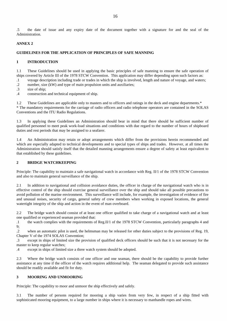
.5 the date of issue and any expiry date of the document together with a signature for and the seal of theAdministration.
ANNEX 2
GUIDELINES FOR THE APPLICATION OF PRINCIPLES OF SAFE MANNING
1 INTRODUCTION
1.1 These Guidelines should be used in applying the basic principles of safe manning to ensure the safe operation ofships covered by Article III of the 1978 STCW Convention. This application may differ depending upon such factors as:.1 voyage description including trade or trades in which the ship is involved, length and nature of voyage, and waters;.2 number, size (kW) and type of main propulsion units and auxiliaries;.3 size of ship;.4 construction and technical equipment of ship.
1.2 These Guidelines are applicable only to masters and to officers and ratings in the deck and engine departments.** The mandatory requirements for the carriage of radio officers and radio telephone operators are contained in the SOLASConventions and the ITU Radio Regulations.
1.3 In applying these Guidelines an Administration should bear in mind that there should be sufficient number ofqualified personnel to meet peak work-load situations and conditions with due regard to the number of hours of shipboardduties and rest periods that may be assigned to a seafarer.
1.4 An Administration may retain or adopt arrangements which differ from the provisions herein recommended andwhich are especially adapted to technical developments and to special types of ships and trades. However, at all times theAdministration should satisfy itself that the detailed manning arrangements ensure a degree of safety at least equivalent tothat established by these guidelines.
2 BRIDGE WATCHKEEPING
Principle: The capability to maintain a safe navigational watch in accordance with Reg. II/1 of the 1978 STCW Conventionand also to maintain general surveillance of the ship.
2.1 In addition to navigational and collision avoidance duties, the officer in charge of the navigational watch who is ineffective control of the ship should exercise general surveillance over the ship and should take all possible precautions toavoid pollution of the marine environment. This surveillance will include, for example, the investigation of evidence of fireand unusual noises, security of cargo, general safety of crew members when working in exposed locations, the generalwatertight integrity of the ship and action in the event of man overboard.
2.2 The bridge watch should consist of at least one officer qualified to take charge of a navigational watch and at leastone qualified or experienced seaman provided that:.1 the watch complies with the requirements of Reg.II/1 of the 1978 STCW Convention, particularly paragraphs 4 and9;.2 when an automatic pilot is used, the helmsman may be released for other duties subject to the provisions of Reg. 19,Chapter V of the 1974 SOLAS Convention;.3 except in ships of limited size the provision of qualified deck officers should be such that it is not necessary for themaster to keep regular watches;.4 except in ships of limited size a three watch system should be adopted.
2.3 Where the bridge watch consists of one officer and one seaman, there should be the capability to provide furtherassistance at any time if the officer of the watch requires additional help. The seaman delegated to provide such assistanceshould be readily available and fit for duty.
3 MOORING AND UNMOORING
Principle: The capability to moor and unmoor the ship effectively and safely.
3.1 The number of persons required for mooring a ship varies from very few, in respect of a ship fitted withsophisticated mooring equipment, to a large number in ships where it is necessary to manhandle ropes and wires.
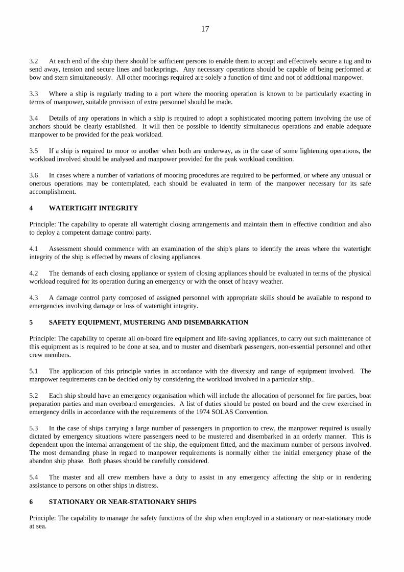
17
3.2 At each end of the ship there should be sufficient persons to enable them to accept and effectively secure a tug and tosend away, tension and secure lines and backsprings. Any necessary operations should be capable of being performed atbow and stern simultaneously. All other moorings required are solely a function of time and not of additional manpower.
3.3 Where a ship is regularly trading to a port where the mooring operation is known to be particularly exacting interms of manpower, suitable provision of extra personnel should be made.
3.4 Details of any operations in which a ship is required to adopt a sophisticated mooring pattern involving the use ofanchors should be clearly established. It will then be possible to identify simultaneous operations and enable adequatemanpower to be provided for the peak workload.
3.5 If a ship is required to moor to another when both are underway, as in the case of some lightening operations, theworkload involved should be analysed and manpower provided for the peak workload condition.
3.6 In cases where a number of variations of mooring procedures are required to be performed, or where any unusual oronerous operations may be contemplated, each should be evaluated in term of the manpower necessary for its safeaccomplishment.
4 WATERTIGHT INTEGRITY
Principle: The capability to operate all watertight closing arrangements and maintain them in effective condition and alsoto deploy a competent damage control party.
4.1 Assessment should commence with an examination of the ship's plans to identify the areas where the watertightintegrity of the ship is effected by means of closing appliances.
4.2 The demands of each closing appliance or system of closing appliances should be evaluated in terms of the physicalworkload required for its operation during an emergency or with the onset of heavy weather.
4.3 A damage control party composed of assigned personnel with appropriate skills should be available to respond toemergencies involving damage or loss of watertight integrity.
5 SAFETY EQUIPMENT, MUSTERING AND DISEMBARKATION
Principle: The capability to operate all on-board fire equipment and life-saving appliances, to carry out such maintenance ofthis equipment as is required to be done at sea, and to muster and disembark passengers, non-essential personnel and othercrew members.
5.1 The application of this principle varies in accordance with the diversity and range of equipment involved. Themanpower requirements can be decided only by considering the workload involved in a particular ship..
5.2 Each ship should have an emergency organisation which will include the allocation of personnel for fire parties, boatpreparation parties and man overboard emergencies. A list of duties should be posted on board and the crew exercised inemergency drills in accordance with the requirements of the 1974 SOLAS Convention.
5.3 In the case of ships carrying a large number of passengers in proportion to crew, the manpower required is usuallydictated by emergency situations where passengers need to be mustered and disembarked in an orderly manner. This isdependent upon the internal arrangement of the ship, the equipment fitted, and the maximum number of persons involved.The most demanding phase in regard to manpower requirements is normally either the initial emergency phase of theabandon ship phase. Both phases should be carefully considered.
5.4 The master and all crew members have a duty to assist in any emergency affecting the ship or in renderingassistance to persons on other ships in distress.
6 STATIONARY OR NEAR-STATIONARY SHIPS
Principle: The capability to manage the safety functions of the ship when employed in a stationary or near-stationary modeat sea.

18
6.1 At present such ships are mainly concerned with offshore exploration and development activities where by thenature of their operations they may carry a large number of specialised personnel with limited knowledge of the maritimeenvironment. It is important that such ships carry a nucleus of adequately trained marine crew to instruct the specialisedpersonnel in the use of safety equipment and evacuation procedures and to assist in the event of an emergency.
6.2 Support services for specialised personnel and their particular requirements should be so arranged as to avoidmaking demands upon the marine crew, which are unrelated to safety.
6.3 All personnel carried on board should be organised and practised in the actions to be taken in typical emergencysituations. Some of these emergency situations will involve their specialist activities.
7 ENGINEERING WATCHKEEPING
Principle: The capability to maintain a safe engineering watch at sea in accordance with Reg.III/1 of the 1978 STCWConvention and also to maintain general surveillance of spaces containing main propulsion and auxiliary machinery.
7.1 The designated duty engineer officer is in effective charge of the engineering watch and should exercise generalsurveillance over the main propulsion machinery, essential ship's equipment and systems necessary for the safe operation ofthe ship's main plant and auxiliary machinery, and avoidance of pollution of the marine environment.
7.2 The engineering watch should consist of not less than one duly qualified engineer officer and may includeappropriate engine-room ratings; it should conform with the requirements of Reg. III/1 of the 1978 STCW Convention. Indesignating the number of personnel assigned to engineering watches, account should be taken of the following:.1 the number, size (kW) and type of the main propulsion and auxiliary units over which surveillance is to bemaintained and the number of machinery spaces containing these units;.2 the adequacy of internal communication;.3 except in ships of limited propulsion power the provision of qualified engineer officers should be such that it is notnecessary for the chief engineer to keep regular watches;.4 except in ships of limited propulsion power a three watch system should be adopted.
Watch arrangements on ships permitted to operate with a reduced manning level based upon automated or periodicallyunattended operation should be consistent with the approval permitting such operation.
7.3 The designated duty engineer officer or other engine room personnel should not be required to keep a watch in anengine room alone or enter the main machinery spaces alone, unless their safety can be confirmed to the navigating bridgeat frequent intervals, either by means of a monitoring system or other equivalent method acceptable to the Administration.
8 OPERATION AND MAINTENANCE OF MACHINERY
Principle: The capability to operate the main propulsion and auxiliary machinery and maintain it in a safe condition toenable the ship to overcome the foreseeable perils of the voyage.
8.1 There should be a sufficient number of qualified personnel to:.1 operate the main propulsion machinery, essential ship's equipment and systems necessary for the safe operation ofthe ship's main plant and auxiliary machinery and to carry out routine maintenance of such machinery, equipment andsystems;.2 meet the possible need to continue the safe operation of the ship for a limited period on a manually operated basis, inthe event of an automation or instrumentation failure.
9 SAFETY ARRANGEMENTS IN MACHINERY SPACES
Principle: The capability to maintain the safety arrangements and the cleanliness of machinery spaces to minimise the riskof fire.
9.1 There should be a sufficient number of designated personnel available to ensure adequate cleanliness of machineryspaces.
9.2 Manning systems may exist whereby crew members, who are not permanently assigned to the engine roomcomplement, are given training in certain engine room duties and work in the engine room for specified limited periods.

19
9.3 Such maintenance as is required to be done at sea should be carried out on engine room fire fighting, fire detectionand fire prevention equipment.
IMO Res A680, (17).
ADOPTED ON 6 NOVEMBER 1991IMO GUIDELINES ON MANAGEMENT FOR THE SAFE OPERATION OF SHIPS AND FOR POLLUTIONPREVENTION
1 INTRODUCTION
1.1 The purpose of these Guidelines is to provide those responsible for the operation of ships (hereinafter called the"Company") with a framework for the proper development, implementation and assessment of safety and pollutionprevention management in accordance with good practice.
1.2 The objective is to ensure safety, to prevent human injury or loss of life, and to avoid damage to the environment, inparticular, the marine environment, and to property.
1.3 Shipping is a varied industry. No two shipping companies are the same and ships operate under a wide range ofdifferent conditions. These Guidelines, therefore, are based on general principles and objectives so as to promote evolutionof sound management and operating practices within the industry as a whole.
2 APPLICATION
2.1 These Guidelines are intended for all companies operating ships and do not seek in any way to define or embracedetailed regulatory requirements, international or national. It is taken for granted that companies comply with suchrequirements.
2.2 These Guidelines are expressed in broad terms so that they can have a widespread application. Clearly, differentlevels of management, whether shore-based or at sea, will require varying levels of knowledge and awareness of the itemsoutlined. Persons with particular responsibilities should have detailed and specialist knowledge of their specific tasks.
2.3 These Guidelines are in a recommendatory form only; however, efforts should be made to apply them to the extentpossible and practicable.
3 BASIC INTERNATIONAL INSTRUMENTS
3.1 The most important means of preventing maritime casualties and pollution of the sea from ships is to design,construct, equip and maintain ships and to operate them with properly trained crews in compliance with internationalconventions and standards relating to maritime safety and pollution prevention.
3.2 To promote this, a number of conventions and other instruments have been developed by IMO and otherinternational organisations, such as:
.1 International Convention for the Safety of Life at Sea (SOLAS);
.2 International Convention for the Prevention of Pollution from Ships (MARPOL 73/78),
.3 International Convention on Load Lines;
.4 Convention on the International Regulations for Preventing Collisions at Sea (COLREG);
.5 International Convention on Standards of Training, Certification and Watchkeeping for Seafarers (STCW);
.6 ILO Convention 147 (Merchant Shipping (Minimum Standards) Convention).

20
4 MANAGEMENT
GENERAL
4.1 Safety, pollution prevention and efficiency are integral to good management. They can only be the result ofstructured, painstaking policy and a combination of the right skills, knowledge and experience. The direct involvement ofdecision-making management in these matters is vital, its attitude being reflected in Company policy and thus directly inthe work of all the Company employees. The cornerstone of good management is commitment from the top.4.2 It is the commitment, competence, attitudes and motivation of all individuals engaged in activities pertaining tosafety and pollution prevention at all levels that determine the end result.4.3 It should be recognised that on board the ship it is the master who has the overriding responsibility for the safeoperation of the ship. It is, therefore, essential to appoint a master competent to command the ship, who is fully conversantwith and dedicated to the maintenance of appropriate safety and environmental protection standards, and to ensure that heis given all the necessary support and authority to perform his duties properly and safely.
Safety and environmental policy
4.4 Individuals and organisations perform well if certain basic principles are adhered to. These principles are brieflyoutlined in the following:
.1 the Company should establish a safety and environmental protection policy with the objectives of safe ship operationand the prevention of pollution. The policy should state these objectives and set out the means of achieving them, in broadterms, taking into account the relevant international conventions and national regulations;
.2 the necessary resources and personnel should be provided for the implementation and functioning of the policy andthe achievement of safe operation and pollution prevention, and
.3 the policy should be clearly explained to all employees. Personnel throughout the Company need to understand thearrangements which have been made and to know which specific duties they have been authorised to carry out, as well asthe level of performance expected. General and specific responsibilities within the Company should be defined explicitly.The arrangements under which the policy will work should be co-ordinated so as to ensure safe and effective operation.
4.5 In drawing up the policy, account should be taken of the following:
.1 the need for concise guidance and instructions on safe operation and pollution prevention, including maintaining thecondition of ships and equipment to conform with the provisions of relevant statutory and classification rules andregulations;
.2 the need for good communication both within the ship and between the ship and management ashore;
.3 the fact that competence, attitudes and motivation are decisive factors in safe operation and pollution prevention andthat the performance of individuals is significantly influenced by the quality of the management systems; and
.4 the fact that accidents can be prevented by proper planning and execution of operations.
4.6 The policy should be reviewed at regular intervals and amended when necessary to ensure that it remains effective.In refining the policy, the importance of discussions and co-operation with Administrations and organisations representingshipowners and seafarers should be recognised.
Designated person ashore
4.7 To ensure the safe operation of their ships and to provide a link between the company and those on board, everycompany should designate a person ashore having direct access to senior management and with the responsibility formonitoring the safety and pollution prevention aspects of the operation of their ships and to ensure that adequate resourcesand the appropriate shore-based support are provided.
Operations documentation
4.8 Guidance and instructions from the company to the master, officers and crew of their ships should be documented ina form which is left to the discretion of owners. A list of suggested subjects for documentation is given in appendix 1. This

21
list is for guidance only and may be varied to take account of the circumstances of the particular ship or its operations. Thedocumentation should also include a statement that it does not affect the master's authority to take such action and issuesuch orders, whether or not they are in accordance with its contents, that may be considered to be necessary for the safety oflife, for the safety of the ship or the prevention of marine pollution. The designated person referred to in 4.7 should beidentified in the appropriate places in the documentation.
Accident reporting
4.9 Accident reporting is essential in order that safe and pollution-free performance can be monitored effectively so thatcorrective action can be taken. The policy should cover the requirements for immediate accident reporting.
4.10 Accidents should be thoroughly investigated and discussed with the personnel involved with a view to avoidingrecurrences. Certain accidents are required to be reported by national law and the policy should remind personnel of theirobligation in this regard.
Suitably qualified seafarers
4.11 Each ship should be manned with qualified, medically fit and suitably experienced seafarers, in accordance with therelevant international and national requirements. In addition, the following items should be considered:
.1 ships should be adequately manned for the trade in which they are engaged;
.2 ship's personnel should have a proper knowledge of the technical aspects of the ship and its operation as necessaryfor the performance of their duties, and receive the necessary training for familiarisation with the particular ship orequipment; and
.3 ship's personnel should receive the relevant information on safety and pollution prevention in English or in thelanguages understood by them.
Other company responsibilities
4.12 The Company, being aware of the basic technical aspects of its ships and the trades in which they are engaged,should be prepared to respond to technical and operational needs. The Company has the responsibility to ensure thatdefects identified by the master are corrected and, where so required, to notify the Administration and classificationsocieties as appropriate. The Company should fully recognise the implications of commercial decisions in terms of safeship operation and pollution prevention.
5 MASTER
5.1 With regard to safety and environmental protection, the master has the responsibility on board a ship for:
.1 implementing the safety and environmental policy of the Company on the basis of international conventions, codesand national legislation;
.2 motivating the crew in the execution of that policy;
.3 issuing appropriate orders and instructions in a clear and simple manner; and
.4 reviewing the safety and pollution prevention procedures.
5.2 In matters of safety and pollution prevention, the master has the overriding authority and discretion to take whateveraction he considers to be in the best interests of passengers, crew, ship and the marine environment.
5.3 The master has the responsibility to report to the Company such defects and other matters which could affect the safeoperation of the ship or could present a risk of pollution, and which require the assistance of the Company to ensure thatthey are rectified.
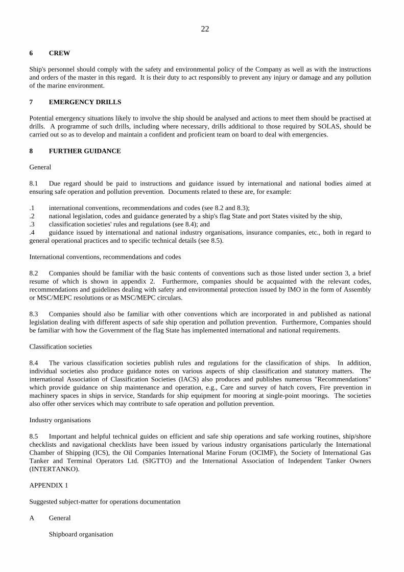
22
6 CREW
Ship's personnel should comply with the safety and environmental policy of the Company as well as with the instructionsand orders of the master in this regard. It is their duty to act responsibly to prevent any injury or damage and any pollutionof the marine environment.
7 EMERGENCY DRILLS
Potential emergency situations likely to involve the ship should be analysed and actions to meet them should be practised atdrills. A programme of such drills, including where necessary, drills additional to those required by SOLAS, should becarried out so as to develop and maintain a confident and proficient team on board to deal with emergencies.
8 FURTHER GUIDANCE
General
8.1 Due regard should be paid to instructions and guidance issued by international and national bodies aimed atensuring safe operation and pollution prevention. Documents related to these are, for example:
.1 international conventions, recommendations and codes (see 8.2 and 8.3);
.2 national legislation, codes and guidance generated by a ship's flag State and port States visited by the ship,
.3 classification societies' rules and regulations (see 8.4); and
.4 guidance issued by international and national industry organisations, insurance companies, etc., both in regard togeneral operational practices and to specific technical details (see 8.5).
International conventions, recommendations and codes
8.2 Companies should be familiar with the basic contents of conventions such as those listed under section 3, a briefresume of which is shown in appendix 2. Furthermore, companies should be acquainted with the relevant codes,recommendations and guidelines dealing with safety and environmental protection issued by IMO in the form of Assemblyor MSC/MEPC resolutions or as MSC/MEPC circulars.
8.3 Companies should also be familiar with other conventions which are incorporated in and published as nationallegislation dealing with different aspects of safe ship operation and pollution prevention. Furthermore, Companies shouldbe familiar with how the Government of the flag State has implemented international and national requirements.
Classification societies
8.4 The various classification societies publish rules and regulations for the classification of ships. In addition,individual societies also produce guidance notes on various aspects of ship classification and statutory matters. Theinternational Association of Classification Societies (IACS) also produces and publishes numerous "Recommendations"which provide guidance on ship maintenance and operation, e.g., Care and survey of hatch covers, Fire prevention inmachinery spaces in ships in service, Standards for ship equipment for mooring at single-point moorings. The societiesalso offer other services which may contribute to safe operation and pollution prevention.
Industry organisations
8.5 Important and helpful technical guides on efficient and safe ship operations and safe working routines, ship/shorechecklists and navigational checklists have been issued by various industry organisations particularly the InternationalChamber of Shipping (ICS), the Oil Companies International Marine Forum (OCIMF), the Society of International GasTanker and Terminal Operators Ltd. (SIGTTO) and the International Association of Independent Tanker Owners(INTERTANKO).
APPENDIX 1
Suggested subject-matter for operations documentation
A General
Shipboard organisation

23
Departmental responsibilitiesReporting proceduresPassenger control, when applicableCommunication between ship and ownerInspections by masters and senior officersProvision and maintenance of documents and recordsMedical arrangementsFitness for duty and avoidance of excessive fatigue Operationaland maintenance instructions for equipment, unless provided separately
B The ship in port
Accepting cargoLoading and discharging procedures, including those relatedto dangerous goodsHarbour watches and patrolsLiaison with shore authoritiesMonitoring trim and stabilityProcedures when the ship is temporarily immobilisedAccidental spillage of liquid cargoes and ship's bunkersUse of reception facilities for oil, noxious liquids and garbageResponse to oil pollution incidents
C Preparing for sea
Verification of passenger numbers, when applicableChecking and recording draughtsChecking stability conditionAssessment of weather conditionsSecuring cargo, hatches and all openings in the hullTests of engines, steering gear, navigation andcommunications equipmentHarbour stationsDocumentation of sailing conditionVerification of pollution prevention equipment andarrangements
D The ship at sea
Bridge and engine-room watchkeeping arrangementsSpecial requirements in bad weather and fogRadio communications, including use of VHFManoeuvring data, unless provided separatelyEmergency procedures other than those covered separatelySecurity patrols, fire patrols and other arrangementsfor surveillanceDischarge into the sea of oily water from machinery spacebilges, cargo residues from oil tankers, noxious liquidsubstances and garbage
Notes:
1 The above list is for guidance only and may be varied to take account of the circumstances of the particular ship orits operations.
2 The operations documentation should include the statement that its contents do not restrict the master's authority totake such steps and issue any orders, whether or not they are in accordance with the contents of the documentation, whichare considered to be necessary for the preservation of life, the safety of the ship or the prevention of marine pollution.

24
APPENDIX 2
MAJOR INTERNATIONAL SHIPPING CONVENTIONS AND RECOMMENDATIONS
Dealing with the ship
SOLAS 74 (International Convention for the Safety of Life at Sea, 1974) as amended, lays down a comprehensive range ofminimum standards for the safe construction of ships and for the basic safety equipment (e.g. fire prevention, navigational,life-saving and radio) to be carried on board.SOLAS also contains operational instructions, particularly on emergency procedures, and provides for regular surveys andfor the issue of certificates of compliance.
The International Bulk Chemical (IBC) and International Gas Carrier(IGC) Codes are mandatory requirements under SOLAS 74.
MARPOL 73/78 (International Convention for the Prevention of Pollution from Ships, 1973, as modified by the Protocol of1978 relating thereto) as amended, contains measures designed to prevent pollution caused both accidentally and in thecourse of routine operations. Five annexes in the Convention cover, respectively, pollution by oil, noxious liquid substancesin bulk, harmful substances carried in packaged forms, sewage and garbage. The International Bulk Chemical (IBC) andthe Bulk Chemical (BCH) Codes are mandatory under MARPOL 73/78.
COLREG (Convention on the International Regulations for Preventing Collisions at Sea, 1972), as amended, lays down thebasic "rules of the road", such as rights of way, safe speed, action to avoid collision, procedures to observe in narrowchannels and in restricted visibility.
International Convention on Load Lines, 1966 sets the minimum permissible freeboard, according to the season of the yearand the trading area of the ship; special ship construction standards are laid down in regard to watertightness.Dealing with the shipowner.
IMO resolution A.441(XI). IMO invited every State to take the necessary steps to ensure that the owner of a ship whichflies the flag of that State provides such State with the current information necessary to enable it to identify and contact theperson contracted or otherwise entrusted by the owner to discharge his responsibilities for that ship in regard to mattersrelating to maritime safety and the protection of the marine environment.
Dealing with the seafarer and the ship
ILO Convention 147 (Merchant Shipping (Minimum Standards) Convention 1976) requires Administrations to haveeffective legislation on safe manning standards, hours of work, seafarers' competency, and social security. It also setsemployment standards equivalent to those contained in a range of ILO instruments (covering e.g., minimum age, medicalcare and examination, social security, training).
Dealing with the seafarer
STCW (International Convention on Standards of Training, Certification and Watchkeeping for Seafarers, 1978) lays downtraining, certification and qualification requirements (including syllabuses and sea time) for senior officers; all officers incharge of watches in the deck, engine and radio departments; and ratings forming part of a watch. All such seafarers arerequired to have a certificate, endorsed in a uniform manner. It also specifies basic principles to be observed in keepingdeck and engine watches and special qualification requirements for personnel on oil, chemical and liquefied gas tankers.
IMO resolution A.481 (XII) (on principles of safe manning) recommended that all Administrations provide each of theirregistered ships with a document specifying the minimum number and grades of qualified seafaring personnel required tobe carried from the safety standpoint. It gives basic principles and detailed guidance to be observed by Administrationswhen assessing the safe manning of ships.
IMO resolution A.443(XI). IMO invited Governments to take the necessary steps to safeguard the shipmaster in the properdischarge of his responsibilities in regard to maritime safety and the protection of the marine environment by ensuring that:
(a) the shipmaster is not constrained by the shipowner, charterer or any other person from taking in this respectany decision which, in the professional judgement of the shipmaster, is necessary;

25
(b) the shipmaster is protected by the appropriate provisions, including the right of appeal, contained in interalia, national legislation, collective agreements or contracts of employment, from unjustifiable dismissal or otherunjustifiable action by the shipowner, charterer or any other person as a consequence of the proper exercise of hisprofessional judgement.
3.3 Are the Minimum Safe Manning or Radio Certificaterequirements with respect to radio qualifications met?IMO Res. A.703 (17)
RECOMMENDATION ON THE TRAINING OF RADIO OPERATORS RELATED TO THE GENERALOPERATOR'S CERTIFICATE
1 GENERAL
1.1 Before training is commenced, the requirements of medical fitness, especially as to hearing, eyesight and speech,should be met by the candidate.
1.2 The training should be relevant to he provisions of the International Convention on Standards of Training,Certification and Watchkeeping for Seafarers (STCW), the provisions of the Radio Regulations annexed to the InternationalTelecommunications Convention (Radio Regulations) and the provision of the International Convention for the Safety ofLife at Sea (SOLAS) then in force, with particular attention to provisions for the global maritime distress and safety system(GMDSS). In developing training requirements, account should be taken of knowledge of the following items, which is notan exhaustive list.
2 THEORY
2.1 Knowledge of the general principals and basic factors necessary for safe and efficient use of all the subsystems andequipment required in the GMDSS sufficient to support the training requirements listed in the practical section of thisannex.
2.2 Knowledge of the use, operation and service areas of the GMDSS subsystems, including satellite systemcharacteristics, navigational and meteorological warning systems and selection of appropriate communication circuits.
3 REGULATIONS AND DOCUMENTATION
The operator should have knowledge of:
.1 the SOLAS Convention and the Radio Regulations with particular emphasis on:
.1.1 distress, urgency and safety radio communications
.1.2 avoiding harmful interference, particularly with distress and safety traffic;
.1.3 prevention of unauthorised transmissions;
.2 other documents relating to operational and communication procedures for distress, safety and publiccorrespondence services, including charges, navigational warnings, and weather broadcasts in the maritime mobile serviceand the maritime mobile-satellite service..3 use of the International Code of Signals and the IMO Standard Marine Navigational Vocabulary.
4 WATCHKEEPING AND PROCEDURES
Training should be given in:
.1 communication procedures and discipline to prevent harmful interference in the GMDSS subsystems
.2 procedures for using propagation prediction information to establish optimum frequencies for communications
.3 radio communications watchkeeping relevant to all GMDSS subsystems, exchange of radio communications traffic,particularly concerning distress, urgency and safety procedures and radio records;.4 use of the international phonetic alphabet;

26
.5 monitoring a distress frequency while simultaneously monitoring or working on at least one other frequency;
.6 ship position reporting systems and procedures;
.7 communication procedures of the IMO Merchant Sip Search and Rescue Manual (MERSAR) using radiocommunications;.8 radio medical systems and procedures
5 PRACTICAL
Practical training should be given in:
.1 correct and efficient operation of all GMDSS subsystems and equipment under normal propagation conditions andunder typical interference conditions.2 safe operation of all the GDMSS communications equipment and ancillary devices, including safety precautions;.3 accurate and adequate keyboard skills for the satisfactory exchange of communications;.4 operational techniques for:.4.1 receiver and transmitter adjustment for the appropriate mode of operation, including digital selective calling anddirect printing telegraphy;.4.2 antenna adjustment and re-alignment as appropriate;.4.3 use of radio life-saving appliances;.4.4 use of emergency position indicating radio beacons (EPIRBs).
6 MISCELLANEOUS
The operator should have knowledge of, and/or receive training in:
.1 the English language, both written and spoken, for the satisfactory exchange of communications relevant to thesafety of life at sea.;
.2 world geography, especially the principal shipping routes, services of rescue co-ordination centres (RCCs) andrelated communications routes;.3 survival at sea, the operation of lifeboats, rescue boats, liferafts, buoyant apparatus and their equipment, with specialreference to the radio installation;.5 preventative measures for the safety of ship and personnel in connection with hazards related to radio equipment,including electrical radiation, chemical and mechanical hazards;.6 first aid, including heart-respiration revival technique;.7 co-ordinated universal time (UTC), global time zones and international date line.
3.5 Does the Operator have a Drug and Alcohol policymeeting OCIMF Guidelines?OCIMF Guidelines For The Control Of Drugs And Alcohol On Board Ship (1995)
Refer to document.
3.10 Does the Operator provide a training policyexceeding statutory requirements?IMO Res. A.680(17)
See 3.2

27
4.NAVIGATION
4.1 Is the navigation equipment as fitted appropriate forthe size of the vessel and in satisfactory condition?
4.1.1 Magnetic compassSOLAS V Reg.12(b)
SOLAS V Regulation 12(b)Shipborne navigational equipment(b)
(i) Ships of 150 gross tonnage and upwards shall be fitted with:
(1) a standard magnetic compass, except as provided in subparagraph (iv);
(2) a steering magnetic compass, unless heading information required under (1) is made available and is clearlyreadable by the helmsman at the main steering position;
(3) adequate means of communication between the standard compass position and the normal navigation controlposition to the satisfaction of the Administration; and
(4) means for taking bearings as nearly as practicable over an arc of the horizon of 360°.
(ii) Each magnetic compass referred to in subparagraph (i) shall be properly adjusted and its table or curve of residualdeviations shall be available at all times.(iii) A spare magnetic compass, interchangeable with the standard compass, shall be carried, unless the steering compassmentioned in subparagraph (i)(2) or a gyro-compass is fitted.(iv) The Administration, if it considers it unreasonable or unnecessary to require a standard magnetic compass, mayexempt individual ships or classes of ships from these requirements if the nature of the voyage, the ship's proximity to landor the type of ship does not warrant a standard compass, provided that a suitable steering compass is in all cases carried.
4.1.2 Gyro Compass and RepeatersSOLAS V Reg.12(d)(e)
SOLAS V Regulation 12(d) (e)Shipborne navigational equipment
(d) Ships of 500 tons gross tonnage and upwards constructed on or after 1 September 1984 shall be fitted with a gyro-compass complying with the following requirements:
(i) The master gyro-compass or a gyro-repeater shall be clearly readable by the helmsman at the main steering position;
(ii) On ships of 1,600 tons gross tonnage and upwards a gyro-repeater or gyro-repeaters shall be provided and shall besuitably placed for taking bearings as nearly as practicable over an arc of the horizon of 360°.

28
(e) Ships of 1,600 tons gross tonnage and upwards, constructed before 1 September 1984, when engaged oninternational voyages, shall be fitted with a gyro-compass complying with the requirements of paragraph (d).
4.1.3 RadarsSOLAS V Reg.12(g),(h), (o), (r),
SOLAS V Regulation 12(g)Shipborne navigational equipment(g) Ships of 500 tons gross tonnage constructed on or after 1 September 1984 and ships of 1600 tons gross tonnageconstructed before 1 September, 1984 shall be fitted with a radar installation. From 1 February, 1995, the radar installationshall be capable of operating in the 9 GHz frequency band. In addition after 1 February, 1995, passenger ships irrespectiveof size and cargo ships of 300 tons gross tonnage and upwards when engaged on international voyages shall be fitted with aradar installation capable of operating in the 9 GHz frequency band. Passenger ships of less than 500 tons gross tonnageand cargo ships of 300 tons gross tonnage and upwards but less than 500 tons gross tonnage may be exempted fromcompliance with the requirements of paragraph (r) at the discretion of the Administration, provided that the equipment isfully compatible with the radar transponder for search and rescue.
SOLAS V Regulation 12(h)Shipborne navigational equipment(h) Ships of 10,000 tons gross tonnage and upwards shall be fitted with two radar installations, each capable of beingoperated independently of the other. From 1 February 1995, at least one of the radar installations shall be capable ofoperating in the 9 GHz frequency band.
SOLAS V Regulation 12(o)Shipborne navigational equipment(o) Except as provided in regulations I/7(b)(ii), I/8 and I/9, while all reasonable steps shall be taken to maintain theapparatus referred to in paragraphs (d) to (n) in efficient working order, malfunctions of the equipment shall not beconsidered as making a ship unseaworthy or as a reason for delaying the ship in ports where repair facilities are not readilyavailable.
SOLAS V Regulation 12(r)Shipborne navigational equipment(r) All equipment fitted in compliance with this regulation shall be of a type approved by the Administration.Equipment installed on board ships on or after 1 September 1984 shall conform to appropriate performance standards notinferior to those adopted by the Organisation. Equipment fitted prior to the adoption of related performance standards maybe exempted from full compliance with those standards at the discretion of the Administration, having due regard to therecommended criteria which the Organisation might adopt in connection with the standards concerned.
4.1.4 Radar plotting equipmentSOLAS V Reg.12(i)
SOLAS V Regulation 12(i)Shipborne navigational equipment(i) Facilities for plotting radar readings shall be provided on the navigating bridge of ships required by paragraph (g) or(h) to be fitted with a radar installation. In ships of 1,600 tons gross tonnage and upwards constructed on or after 1September 1984 the plotting facilities shall be at least as effective as a reflection plotter.
4.1.5 ARPASOLAS V Reg.12(j)
SOLAS V Regulation 12(j)Shipborne navigational equipment
(i) An automatic radar plotting aid shall be fitted on
(1) ships of 10,000 tons gross tonnage and upwards, constructed on or after 1 September 1984
(2) tankers constructed before 1 September 1984 as follows:(aa) if of 40,000 tons gross tonnage and upwards by 1 January 1985
29
(bb) if of 10,000 tons gross tonnage and upwards but less than 40,000 tons gross tonnage, by 1 January 1986.
(3) Ships constructed before 1 September 1984, that are not tankers, as follows:(aa) if of 40,000 tons gross tonnage and upwards by 1 September 1986(bb) if of 20,000 tons gross tonnage and upwards, but less than 40,000 tons gross tonnage, by 1 September
1987;(cc) if of 15,000 tons gross tonnage and upwards, but less than 20,000 tons gross tonnage, by 1 September
1988.
(ii) Automatic radar plotting aids fitted prior to September 1984 which do not fully conform to the performancestandards adopted by the Organisation may, at the discretion of the Administration, be retained until 1 January 1991.
(iii) The Administration may exempt ships from the requirements of this paragraph, in cases where it considers itunreasonable or unnecessary for such equipment to be carried, or when the ships will be taken permanently out of servicewithin two years of the appropriate implementation date.
4.1.6 Echo soundersSOLAS V Reg.12(k)
SOLAS V Regulation 12(k)Shipborne navigational equipment(k) When engaged on international voyages ships of 1,600 tons gross tonnage and upwards constructed before 25 May1980 and ships of 500 tons gross tonnage and upwards constructed on or after 25 May 1980 shall be fitted with an echo-sounding device.
4.1.7 Speed and distance indicatorsSOLAS V Reg.12(l)
SOLAS V Regulation 12(l)Shipborne navigational equipment(l) When engaged on international voyages ships of 500 tons gross tonnage and upwards constructed on or after 1September 1984 shall be fitted with a device to indicate speed and distance. Ships required by paragraph (j) to be fittedwith an automatic radar plotting aid shall be fitted with a device to indicate speed and distance through the water.
4.1.8 Rudder angle, RPM, variable pitch and bow thruster indicatorsSOLAS V Reg.12(m)
SOLAS V Regulation 12(m)Shipborne navigational equipment(m) Ships of 1,600 tons gross tonnage and upwards constructed before 1 September 1984 and all ships of 500 tons grosstonnage and upwards constructed on or after 1 September 1984 shall be fitted with indicators showing the rudder angle, therate of revolution of each propeller and , in addition, if fitted with variable pitch propellers or lateral thrust propellers, thepitch and operational mode of such propellers. All these indicators shall be readable from the conning position.
4.1.9 Rate of turn indicatorsSOLAS V Reg.12(n)
SOLAS V Regulation 12(n)Shipborne navigational equipmentShips of 100,000 tons gross tonnage and upwards constructed on or after 1 September 1984 shall be fitted with a rate-of-turn indicator.
4.1.10 Signal lamps (Aldis)SOLAS V Reg.11
SOLAS V Regulation 11Signalling LampsAll ships of over 150 tons gross tonnage, when engaged on international voyages, shall have on board an efficient daylightsignalling lamp which shall not be solely dependent upon the ship's main source of electrical power.

30
4.1.11 VHF Radio SOLAS IV/7 See 11.1 4.1.12 Navtex ReceiverSOLAS IV/7
See 11.1
4.2 Is the vessel provided with Operator’s policystatements, instructions and procedures with regard tosafe navigation?
4.2.4 Are the vessel’s manoeuvring characteristics displayed on the bridge?SOLAS II-1 Reg.28.3IMO Res. A. 601(15)
SOLAS II-1/28.3Means of going asternThe stopping times, ship headings and distances recorded on trials, together with the results of trials to determine theability of ships to have multiple propellers to navigate and manoeuvre with one or more propellers inoperative, shall beavailable on board for the use of the master or designated personnel.
IMO Res A601(15)
Refer to document
4.2.5 Are Auto to Manual steering changeover procedures displayed?SOLAS V Reg.19
SOLAS V Regulation 19Use of the automatic pilot.(a) In areas of high traffic density, in conditions of restricted visibility and in all other hazardous navigational situationswhere the automatic pilot is used, it shall be possible to establish human control of the ship's steering immediately.
(b) In circumstances as above, it shall be possible for the officer of the watch to have available without delay, theservices of a qualified helmsman who shall be ready at all times to take over steering control.
(c) The change-over from automatic to manual steering and vice versa shall be made by or under the supervision of aresponsible officer.
(d) The manual steering shall be tested after prolonged use of the automatic pilot, and before entering areas wherenavigation demands special caution.

31
4.4 Are the Standing Order and Master's Night OrderBooks in effective use?ICS Bridge Procedures Guide
1.3.1 Master's standing orders
Shipboard operational procedures manuals supported by standing instructions based upon the company's navigation policyshould form the basis of command and control on board.
Master's standing orders should be written to reflect the master's own particular requirements and circumstances particularto the ship, her trade and the experience of the bridge team employed at that point in time.
Standing orders and instructions should operate without conflict within the ship's safety management system.
Standing orders should be read by all officers before the commencement of the voyage and signed accordingly. A copy ofthe orders should be available on the bridge for reference.
1.3.1.1 Bridge order book
In addition to general standing orders, specific instructions may be needed for special circumstances.
At night the master should write in the bridge order book what is expected of the 00W. These orders must be signed by each00W when going on watch.
4.5 Has a system been established to ensure that nauticalpublications, charts and information are on board andcurrent?SOLAS V Reg. 20
SOLAS V Regulation 20Nautical publicationsAll ships shall carry adequate and up-to-date charts, sailing directions, lists of lights, notices to mariners, tide tables and allother nautical publications necessary for the intended voyage.
4.5.2 Are Light Lists, Sailing Directions, Pilot Books, The Nautical Almanac and Chart Catalogue thecurrent editions?SOLAS V Reg.20
See 4.5
4.6 Has the vessel been safely navigated, and incompliance with international regulations?SOLAS V Reg.20
See 4.5

32
4.6.1 Are charts in use appropriate for the port?SOLAS V Reg.20
See 4.5
4.7 Is a comprehensive passage plan available for thecurrent voyage and does it cover the full voyage fromberth to berth?STCW Code Section A-VIII/2 PART 2 para. 5. UK Maritime and Coastguard Agency, Marine GuidanceNote 72 (Guide to the Planning and Conduct of Passages)
Planning prior to each voyage
Prior to each voyage the master of every ship shall ensure that the intended route from the port of departure to the first portof call is planned using adequate and appropriate charts and other nautical publications necessary for the intended voyage,containing accurate, complete and up-to-date information regarding those navigational limitations and hazards which are ofa permanent and predictable nature and which are relevant to the safe navigation of the ship.
UK Maritime and Coastguard Agency Marine Guidance Note 72 (Guide to the Planning and Conduct ofPassages)
Refer to document
4.8 Does the Operator provide formal training in bridgeteam management techniques?STCW Convention. Res.8
Promotion of technical knowledge, skills and professionalism of seafarers
The conference,
HAVING ADOPTED the 1995 amendments to the International Convention on Standards of Training, Certification andWatchkeeping for Seafarers, 1978, with a view to strengthening the implementation of the Convention and therebyimproving the competence of seafarers,
APPRECIATING that the overall effectiveness of selection, training and certification processes can only be evaluatedthrough the skills, abilities and competence exhibited by seafarers during the course of their service on board ship,
RECOMMENDS that Administrations should make arrangements to ensure that companies:
.1 establish criteria and processes for the selection of personnel exhibiting the highest practicable standards of technicalknowledge, skills and professionalism;
.2 monitor the standards exhibited by ship’s personnel in the performance of their duties;
.3 encourage all officers to participate actively in the training of junior personnel;
.4 monitor carefully and frequently review the progress made by junior personnel in their acquisition of knowledge andskills during their service on board ship;
.5 provide refresher and updating training at suitable intervals as may be required; and
.6 take all appropriate measures to encourage pride of service and professionalism on the part of the personnel theyemploy.

33
4.9 Is position fixing satisfactory?Ref:- STCW Code Section A-VIII/2 Part 3-1 (24)
Performing the navigational watch
24 During the watch the course steered, position and speed shall be checked at sufficiently frequent intervals, using anyavailable navigational aids necessary, to ensure that the ship follows the planned course.
4.10 Is the gyro and magnetic Compass Error Logmaintained and is it up to date?STCW Code Section A-VIII/2 Part 3-1 (34)
Performing the navigational watch
34 The officer in charge of the navigational watch shall make regular checks to ensure that:
.2 the standard compass error is determined at least once a watch and, when possible, after any major alteration ofcourse; the standard and gyro compasses are frequently compared and repeaters are synchronised with their master compass
4.11 Are current navigation warnings and weatherforecasts available?Ref: SOLAS Ch.V Reg. 2 and 4
Regulation 2Danger messages
(b) Each contracting Governments will take all steps necessary to ensure that when intelligence of any of the dangersspecified in paragraph (a) of this regulation is received, it will be promptly brought to the knowledge of those concernedand communicated to other interested Governments
Regulation 4Meteorological services
(b) In particular, the contracting Governments undertake to co-operate in carrying out, as far as practicable, thefollowing meteorological arrangements.
(i) To warn ships of gales, storms, tropical storms, both by the issue of radio messages and by the display of appropriatesignals at coastal points.
(ii) To issue daily, by radio, weather bulletins suitable for shipping, containing data of existing weather, waves and ice,forecasts and, when practicable, sufficient additional information to enable simple weather charts to be prepared at sea andalso to encourage the transmission of suitable.

34
5.SAFETY MANAGEMENT
5.1 Is a satisfactory level of safety management beingdemonstrated?
5.1.5 Are smokerooms identified?ISGOTT 4.8
4.8 SMOKING
4.8.1 Controlled smoking
Smoking should only be permitted under controlled conditions. A total prohibition on smoking at terminals and on a tankerat a berth is in general unrealistic and unenforceable and may give rise to surreptitious smoking. There may, however, beoccasions when owing to the nature of the cargo being transferred or other factors, a total prohibition on smoking will benecessary. In such cases a regular inspection should be made by a responsible officer to ensure that this prohibition isenforced.
Smoking should be strictly prohibited within the restricted area enclosing all tanker berths and on board any tanker while ata berth, except in designated smoking places
4.8.2 Location of Designated Smoking Places
The designated smoking places on a tanker or on shore should be agreed in writing between the master and the terminalrepresentative before operations start. The master is responsible for ensuring that all persons on board the tanker areinformed of the selected places for smoking and for posting suitable notices in addition to the tanker's permanent notices
Certain criteria should be followed in the selection of smoking places whenever petroleum cargoes are being handled orwhen ballasting, purging with inert gas, gas freeing and tank cleaning operations are taking place.
The criteria are:
• The agreed smoking places should be confined to locations abaft the cargo tanks, except when the entry of petroleumgas into midships accommodation is highly improbable
• The agreed smoking places should not have doors or ports which open directly on to open decks.
• Account should be taken of conditions that may suggest danger, such as an indication of unusually high petroleumgas concentrations, particularly in the absence of wind and when there are operations on adjacent tankers or on the jettyberth.
In the designated smoking places all ports should be kept closed and doors into passageways should be kept closed exceptwhen in use.

35
While the tanker is moored at the terminal, even when no operations are in progress, smoking can only be permitted indesignated smoking places, or after there has been prior agreement in writing between the master and terminalrepresentative, in any other closed accommodation.
When stern loading/discharge connections are being used particular care must be taken to ensure that no smoking isallowed in any accommodation or space, the door or ports of which open on to the deck where the stern loading/dischargemanifold is located.
5.1.6 Are all required external doors, ports and windows kept closed in port?ISGOTT 6.1.2
In the accommodation all external doors, ports and similar openings which lead directly from the tank deck to theaccommodation or machinery spaces (other than the pumproom), or which overlook the tank deck at any level, or whichoverlook the poop deck forward of the funnel should be kept closed. A screen door cannot be considered a safe substitutefor an external door.
Additional doors and ports may have to be closed in special circumstances, such as during stern loading, or due to structuralpeculiarities of the tanker.
If doors have to be opened for access they should be closed immediately after use.
Doors that must be kept closed should be clearly marked, but in no case should doors be locked.
5.1.7 Are there sufficient crew on board at time of the inspection to handle emergency situations?STCW Conv. Annex Ch. VII. Reg.VIII/2 .4
Watchkeeping arrangements and principles to be observed.
2 Administrations shall require the master of every ship to ensure that watchkeeping arrangements are adequate formaintaining a safe watch or watches, taking into account the prevailing circumstances and conditions and that, under themaster’s general direction:
.4 an appropriate and effective watch or watches are maintained for the purpose of safety at all times, while the ship isat anchor or moored and, if the ship is carrying hazardous cargo, the organisation of such watch or watches takes into fullaccount, the nature, quantity, packing and stowage of the hazardous cargo and of any special conditions prevailing onboard, afloat or ashore.
5.1.8 Is a fire control plan exhibited within the accommodation and also available externally?SOLAS II-2 Reg.20; ISGOTT 4.7
SOLAS II-2 Regulation 20Fire control plans1 In all ships general arrangement plans shall be permanently exhibited for the guidance of the ship's officers,showing clearly for each deck the control stations, the various fire section enclosed by "A" class divisions, the sectionsenclosed by "B" class divisions together with particulars of the fire detection and fire alarm systems, the sprinklerinstallation, the fire-extinguishing appliances, means of access to different compartments, decks etc. and the ventilatingsystem including particulars of the fan control positions, the position of dampers and identification numbers of theventilating fans serving each section. Alternatively, at the discretion of the Administration, the aforementioned details maybe set out in a booklet, a copy of which shall be supplied to each officer, and one copy shall at all times be available onboard in an accessible position. Plans and booklets shall be kept up-to-date, any alterations being recorded thereon as soonas practicable. Description in such plans and booklets shall be in the official language of the Flag State. If the language isneither English nor French, a translation into one of those languages shall be included. In addition, instructionsconcerning the maintenance and operation of all equipment and installations on board for the fighting and containment offire shall be kept under one cover, readily available in an accessible position.
2 In all ships a duplicate set of fire control plans or a booklet containing such plans shall be permanently stored in aprominently marked weathertight enclosure outside the deckhouse for the assistance of shoreside fire-fighting personnel.

36
ISGOTT 4.7
See 5.1.9
5.1.9 Are necessary safety signs and other important information prominently displayed?ISGOTT 4.7 SOLAS III B-Reg.8, 37
ISGOTT 4.7 NOTICES4.7.1 Notices on the TankerOn arrival at a terminal, a tanker should display notices at the gangway in appropriate languages stating:
WARNINGNO NAKED LIGHTSNO SMOKINGNO UNAUTHORISED PERSONS
Alternative wording containing the same warnings may also be used.
Notices stating "EMERGENCY ESCAPE ROUTES" (with directional signs) should also be displayed at appropriatelocations.
In addition, notices are displayed on board tankers which are primarily for the information of the crew. Shore personnelshould also observe these requirements when on board the tanker.
4.7.2 Notices on the TerminalPermanent notices and signs indicating that smoking and naked lights are prohibited should be conspicuously displayed ona jetty in appropriate languages. Similar permanent notices and signs should be displayed at the entrance to the terminalarea or the shore approaches to a jetty.
In buildings and other shore locations where smoking is allowed, appropriate notices should be conspicuously displayed.
Emergency escape routes from the tanker berth to the shore should be clearly indicated.
SOLAS III Part B-Reg. 8Muster list and emergency instructions
1 This regulation applies to all ships.
2 Clear instructions to e followed in the event of an emergency shall be provided for every person on board. In thecase of passenger ships these instructions shall be drawn up in the language or languages required by the ship’s flag stateand in the English language.
3 Muster lists and emergency instructions complying with the requirements of regulation 37 shall be exhibited inconspicuous places throughout the ship including the navigation bridge, engine room, and crew accommodation spaces.
4 Illustrations and instructions in appropriate languages shall be posted in passenger cabins and be conspicuouslydisplayed at muster stations and other passenger spaces to inform passengers of:
.1 their muster station
.2 the essential actions they must take in an emergency; and
.3 the method of donning lifejackets.
SOLAS III Part B-Reg. 37Muster list and emergency instructions
1 The muster list shall specify details of the general emergency alarm and public address system prescribed insection7.2 of the Code and also action to be taken by crew and passengers when this alarm is sounded. The muster list shallshow how the order to abandon ship will be given.2 Each passenger ship shall have procedures in place for locating and rescuing passengers trapped in their staterooms.3 The muster list shall show the duties assigned to the different members of the crew including:
.1 closing of the watertight doors, fire doors, valves, scuppers, sidescuttles, skylights and other similaropenings in the ship;

37
.2 equipment of the survival craft and other lifesaving appliances; .3 preparation and launching of survival craft; .4 general preparations of other lifesaving appliances; .5 muster of passengers; .6 use of communications equipment; .7 manning of fire parties assigned to deal with fires; and, .8 special duties assigned in respect to the use of fire fighting equipment and installations
4 The muster list shall specify which officers are assigned to ensure that life-saving and fire appliances are maintained ingood condition and are ready for immediate use.5 The muster list shall specify substitutes for key personnel who may become disabled, taking into account that differentemergencies may call for different actions.6 The muster list shall show the duties assigned to members of the crew in relation to passengers in case of emergency.These duties shall include:
.1 warning the passengers;
.2 seeing that they are suitably clad and have donned their lifejackets correctly;
.3 assembling passengers at their muster stations;
.4 keeping order in the passageways and on the stairways and generally controlling the movements of thepassengers; and
.5 ensuring that a supply of blankets is taken to the survival craft
7. The muster list shall be prepared before the ship proceeds to sea. After the muster list has been prepared, if anychanges take place in the crew which necessitates an alteration in the muster list, the master shall either revise the list orprepare a new list.8. The format of the muster list on passenger ships shall be approved
5.1.10 Is personal protective equipment such as boiler suits, safety footwear, eye and ear protectionand safety harnesses, etc. provided and, as required, being worn? ISGOTT 2.6 SOLAS II-1 Reg.36
2.6 SYNTHETIC CLOTHING
Experience has shown that clothing made from synthetic material does not give rise to any significant electrostatic hazardunder conditions normally encountered on tankers.
However, the tendency for synthetic material to melt and fuse together when exposed to high temperatures leads to aconcentrated heat source which causes severe damage to body tissue. Clothing made of such material is therefore notconsidered suitable for persons who may, in the course of their duties be exposed to flame or hot surfaces
SOLAS II-1 Regulation 36Protection against noiseMeasures shall be taken to reduce machinery noise in machinery spaces to acceptable levels as determined by theAdministration. If this noise cannot be sufficiently reduced the source of excessive noise shall be suitably insulated orisolated or a refuge from noise shall be provided if the space is required to be manned. Ear protectors shall be provided forpersonnel required to enter such spaces if necessary.
5.1.11 Is the accommodation air conditioning system on re-circulation during cargo operations?ISGOTT 6.1.1; 6.1.4; Appendix A. Ship/Shore Safety Checklist
6.1 OPENINGS IN SUPERSTRUCTURES
6.1.1. General
A tanker's accommodation normally contains equipment which is not suitable for use in flammable atmospheres. It istherefore imperative that petroleum gas is kept out of the accommodation.
All external openings should be closed when the tanker, or a ship at an adjacent berth, is conducting any of the followingoperations:
• Handling volatile petroleum or non-volatile petroleum near to or above its flashpoint.

38
• Loading non-volatile petroleum into tanks containing hydrocarbon vapour.
• Crude oil washing.
• Ballasting, purging, gas freeing or tank washing after discharge of volatile petroleum.
Although discomfort may be caused to personnel in accommodation that is completely closed during conditions of hightemperatures and humidity, this discomfort should be accepted in the interests of safety.
6.1.4 Central Air Conditioning and Mechanical Ventilating Systems
Intakes of central air conditioning or mechanical ventilating systems should be adjusted to prevent the entry of petroleumgas, if possible by re-circulation of air within the enclosed spaces.
If at any time it is suspected that gas is being drawn into the accommodation, central air conditioning and mechanicalventilating systems should be stopped and the intakes closed and/or covered.
Appendix A. Ship/Shore Safety Checklist. Part “A” Bulk Liquid General
Question 25: Are air conditioning intakes which may permit the entry of cargo vapours closed?
5.2 Is a completed ISGOTT Ship/Shore Safety Checklistavailable?ISGOTT Appendix A; OCIMF STS Guide (Petroleum)
Refer to documents.
5.3 Is the vessel provided with a safe means of access?ISGOTT 4.6; SOLAS V Reg. 17
ISGOTT 4.6 ACCESS BETWEEN SHIP AND SHORE
4.6.1 Means of Access
Personnel should use only the designated means of access between ship and shore.
Gangways or other means of access should be provided with an effective safety net where appropriate. Lifebuoy withlifelines should be available in the vicinity of the gangway or other means of access. In addition, suitable life savingequipment, should be available near the access point ashore.
Means of access should be placed as close as possible to crew accommodation and as far away as possible from themanifold.
4.6.2 Gangway Landing
When terminal access facilities are not available and a tanker's gangway is used, the berth must have sufficient landingareas to provide the gangway with an adequate clear run in order to maintain safe, convenient access to the tanker at allstates of the tide and changes of freeboard.

39
Particular attention to safe access should be given where the difference in level between the decks of the tanker and jettybecomes large. There should be special facilities at berths where the level of a tanker's deck can fall well below that of thejetty. For emergency escape provisions see Chapter 14.
4.6.3 Lighting
During darkness, the means of access to the tanker should be well lit.
4.6.4 Unauthorised Persons
Persons who have no legitimate business on board, or do not have the master's permission, should be refused access to atanker. The terminal. in agreement with the master should restrict access to the jetty or berth.
A crew list should be given to the terminal security personnel.
4.6.5 Persons Smoking or Intoxicated
Personnel on duty on a jetty or on watch on a tanker must ensure that no one who is smoking approaches the jetty or boardsa tanker. Persons apparently intoxicated should not be allowed to board a tanker unless they can be properly supervised.
SOLAS V Regulation 17
Pilot transfer arrangements
(a) Application
(i) Ships engaged on voyages in the course of which pilots are likely to be employed shall be provided withpilot transfer arrangements.
(ii) Equipment and arrangements for pilot transfer which are installed on or after 1 January 1994 shall complywith the requirements of this regulation and due regard shall be paid to the standards adopted by theOrganization.*
(iii) Equipment and arrangements for pilot transfer which are installed before 1 January 1994 shall at leastcomply with the requirements of regulation 17 in force prior to that date and due regard shall be paid to thestandards adopted by the Organization prior to that date.**
(iv) Equipment and arrangements which are replaced after 1 January 1994 shall, in so far as is reasonable andpracticable, comply with the requirements of this regulation.
(b) General
(i) All arrangements used for pilot transfer shall efficiently fulfil their purpose of enabling pilots to embark anddisembark safely. The appliances shall be kept clean, properly maintained and stowed and shall beregularly inspected to ensure that they are safe to use. They shall be used solely for the embarkation anddisembarkation of personnel.
(ii) The rigging of the pilot transfer arrangements and the embarkation and disembarkation of a pilot shall besupervised by a responsible officer having means of communication with the navigation bridge.Personnel engaged in rigging and operating any mechanical equipment shall be instructed in the safeprocedures to be adopted and the equipment shall be tested prior to use.
(c) Transfer arrangements
(i) Arrangements shall be provided to enable the pilot to embark and disembark safely on either side of the ship.
(ii) In ships where the distance from sea level to the point of access to, or egress from, the ship exceeds 9 metres, andwhen it is intended to embark or disembark pilots by means of the accommodation ladder, or by means ofmechanical pilot hoists or other equally safe and convenient means in conjunction with a pilot ladder, the shipshall carry such equipment on each side, unless the equipment is capable of being transferred for use on eitherside.

40
(iii) Safe and convenient access to, and egress from, the ship shall be provided by either:
(1) a pilot ladder requiring a climb of not less than 1.5 metres and not less than 9 metres above the water sopositioned and secured that:
(aa) It is clear of any possible discharge from the ship;(bb) It is within the parallel body of the ship and, is as far as is practicable, within the mid-ship half
length of the ship;(cc) each step rests firmly against the ship's side; where constructional features, such as rubbing bands,
would prevent the implementation of this provision, special arrangements shall, to the satisfactionof the Administration, be made to ensure that persons are able to embark and disembark safely;
(dd) the single length of pilot ladder is capable of reaching the water from the point of access to, oregress from, the ship and due allowance is made for all conditions of loading and trim of the shipand for an adverse list of 15o; the securing strongpoints, shackles and securing ropes shall be atleast as strong as the side ropes;
(2) an accommodation ladder in conjunction with the pilot ladder, or other equally safe and convenient means,whenever the distance from the surface of the water to the point of access to the ship is more than 9 metres.The accommodation ladder shall be sited leading aft. When is use, the lower end of the accommodationladder shall rest firmly against the ship’s side within the parallel body length of the ship and, as far as ispracticable, within the mid-ship half length and clear of all discharges; or
(3) a mechanical pilot hoist so located that it is within the parallel body length of the ship and, as far as ispracticable, within the mid-ship half length and clear of all discharges.
(d) Access to the ship’s deck
Means shall be provided to ensure safe, convenient and unobstructed passage for any person embarking on, ordisembarking from , the ship between the head of the pilot ladder, or of any accommodation ladder or otherappliance, and the ship’s deck. Where such passage is by means of:
(i) a gateway in the rails or bulwark, adequate handholds shall be provided;(ii) a bulwark ladder, two handhold stanchions rigidly secured to the ship’s structure at or near their bases and
at higher points shall be fitted. The bulwark ladder shall be securely attached to the ship to preventoverturning.
(e) Shipside doors
Shipside doors used for pilot transfer shall not open outwards.
(f) Mechanical pilot hoists
(i) The mechanical pilot hoist and its ancillary equipment shall be of a type approved by the Administration.The pilot hoist hall be designed to operate as a moving ladder to lift and lower one person on the side of theship, or as a platform to lift or lower one or more persons on the side of the ship. It shall be of such designand construction as to ensure that the pilot can be embarked and disembarked in a safe manner, including asafe access from the hoist to the deck and vice versa. Such access shall be gained directly by a platformsecurely guarded by handrails.
(ii) Efficient hand gear shall be provided to lower or recover the person or persons carried, and kept ready foruse in the event of power failure.
(iii) The hoist shall be securely attached to the structure of the ship. Attachment shall not be solely by means ofthe ship’s side rails. Proper and strong attachments shall be provided for hoists of the portable type on eachside of the ship.
(iv) If belting is fitted in the way of the hoisting position, such belting shall be cut back sufficiently to allow thehoist to operate against the ship’s side.

41
(v) A pilot ladder shall be rigged adjacent to the hoist and available for immediate use so that access to it isavailable from the hoist at any point of its travel. The pilot ladder shall be capable of reaching the sea levelfrom its own point of access to the ship.
(vi) The position on the ship’s side where the hoist will be lowered shall be indicated.
(vii) An adequate protected stowage position shall be provided for the portable hoist. In very cold weather, toavoid the danger of ice formation, the hoist shall not be rigged until its use is imminent.
(g) Associated equipment
(i) The following associated equipment shall be kept at hand ready for immediate use when persons are beingtransferred:
(1) two man-ropes of not less than 28mm in diameter properly secured to the ship if required by thepilot;
(2) a lifebuoy equipped with self-igniting light;(3) a heaving line.
(ii) When required by paragraph (d), stanchions and bulwark ladders shall be provided.
(h) Lighting
Adequate lighting shall be provided to illuminate the transfer arrangements overside, the position on deck where aperson embarks or disembarks and the controls of the mechanical pilot hoist.
* Refer to the Recommendations on pilot transfer arrangements adopted by the Organization by resolution A.667(16)**Refer to the Recommendation on performance standards for mechanical pilot hoists, adopted by the Organization byresolution A.275 (VIII), and to the Recommendations on arrangements for embarking and disembarking pilots in very largeships adopted by the Organization by resolution A.426(XI).
5.3.5 If a helicopter landing or winching area is provided, does it meet ICS guidelines?ICS Helicopter/Ship Operations
See Inspector guidance and refer to document.
5.5 Are officers familiar with the operation of fire fighting,life saving and other emergency equipment?STCW Convention Ch. V Reg. V/1; STCW Code Ch.VI Tables A-VI/1-1, A-VI/1-2, A-VI/3
STCW Convention Reg. V/1Mandatory minimum requirements for the training and qualification ofmasters, officers and ratings on tankers
1. Officers and ratings assigned specific duties and responsibilities related to cargo or cargo equipment on tankers shallhave completed an approved shore based fire-fighting course in addition to the training required by regulation VI/1 andshall have completed:
.1 at least three months of approved seagoing service on tankers in order to acquire adequate knowledge of safeoperational practices; or.2 an approved tanker familiarization course covering at least the syllabus given for that course in section A-V/1 of theSTCW Code, so, however that the Administration may accept a period of supervised seagoing service shorter than thatprescribed by sub-paragraph .1, provided :.3 the period so accepted is not less than one month;.4 the tanker is of less than 3,000 gross tonnage;

42
.5 the duration of each voyage on which the tanker is engaged during the period does not exceed 72 hours; and,
.6 the operational characteristics of the tanker and the number of voyages and loading and discharging operationscompleted during the period allow the same level of knowledge to be acquired.
2. Masters, chief engineer officers, chief mates, second engineer officers and any person with immediate responsibilityfor loading, discharging and care in transit or handling of cargo shall, in addition to meeting the requirements of sub-paragraphs 1.1 or 1.2, have:
.1 experience appropriate to their duties on the type of tanker on which they serve; and
.2 completed an approved specialized training programme which at least covers the subjects set out in section A-V/1 ofthe STCW Code that are appropriate to their duties on the oil tanker, chemical tanker or liquefied gas tanker on which theyserve.
3. Within two years after entry into force of the Convention for a Party, seafarers may be considered to have met therequirements of sub-paragraph 2.2 if they have served in a relevant capacity on board the type of tanker concerned for aperiod of not less than one year within the preceding five years.
4. Administrations shall ensure that an appropriate certificate is issued to masters and officers, who are qualified inaccordance with paragraphs 1 or 2 as appropriate, or that an existing certificate is duly endorsed. Every rating who is soqualified shall be duly certificated.
STCW Code Ch.VI Tables A-VI/1-1; A-VI/1-2; A-VI/3
Refer to documents
5.6 Is the verbal communication between the ship andshore acceptable?ISGOTT 4.5
ISGOTT 4.5 COMMUNICATIONS
Telephone, portable VHF/UHF and radio telephone systems should comply with the appropriate safety requirements.
The provision of adequate means of communication, including a back-up system between ship and shore, is theresponsibility of the terminal.
Communication between the responsible officer on duty and the responsible person ashore should be maintained in the mostefficient way.
When telephones are used, the telephone both on board and ashore should be continuously manned by persons who canimmediately contact their superior. Additionally, it should be possible for that superior to override all calls. WhenVHF/UHF or radiotelephone systems are used, units should preferably be portable and carried by the responsible officer onduty and the responsible person ashore, or by persons who can contact their respective superior immediately. Where fixedsystems are used, the above guidance for telephones should be followed.
The selected system of communication together with the necessary information on telephone numbers and/or channels to beused should be recorded on an appropriate form. This form should be signed by both ship and shore representatives.
Where there are difficulties in verbal communication, these can be overcome by appointing a person with adequatetechnical and operational knowledge and a sufficient command of a language understood by both ship and shore personnel.

43
5.7 Are enclosed space and pumproom entry proceduresidentified and complied with?ISGOTT 2.16/17, Ch.11, Appendix I
ISGOTT2.16 ENTRY INTO ENCLOSED SPACES
Because of the possibility of oxygen deficiency as well as the presence of hydrocarbon or toxic gas in a cargo tank,cofferdam, double bottom tank or any enclosed space, it is the master's responsibility to identify such spaces and to establishprocedures for safe entry. Guidance is to be found in Chapter 11.
Personnel should consult the responsible officer to determine whether entry into such enclosed spaces is permitted. It is theduty of the responsible officer to check the atmosphere in the compartment, ventilate the space, ensure the appropriateprocedures are followed, ensure the safety of the personnel concerned, and issue an entry permit.
2.17 PUMPROOMS
2.17.1 General Precautions
Cargo pumprooms, by virtue of their location, design and operation which require the space to be routinely entered bypersonnel, constitute a particular hazard and therefore necessitate special precautions. A pump-room contains the largestconcentration of pipelines of any space within the ship and leakage of a volatile product from any part of this system couldlead to the rapid generation of a flammable or toxic atmosphere. The pumproom may also contain a number of potentialignition sources unless formal, structured maintenance, inspection and monitoring procedures are strictly adhered to.
2.17.2 Routine Maintenance and Housekeeping Issues
Pump-room bilges should be kept clean and dry. Particular care should be taken to prevent the escape of hydrocarbonliquids or vapour into the pump-room.
It is important that the integrity of pipelines and pumps is maintained and any leaks are detected and rectified in a timelyfashion. Pipelines should be visually examined and subjected to routine pressure tests to verify their condition. Other meansof non-destructive testing or examination, such as ultra-sonic wall thickness measurement, may be considered appropriate,but should always be supplemented by visual examination.
Procedures should be established to verify that mud boxes and filters are properly sealed after the have been opened up forroutine inspection or examination.
Valve glands and drain cocks should be regularly inspected to ensure that they do not leak.
Bulkhead penetrations should be routinely checked to ensure their effectiveness.
The security of critical bolts on the cargo pumps and associated fittings such as pedestal fixing bolts and securing shaftguards, should be ensured. In addition, requirements for their examination should be included in routine maintenanceprocedures.
2.17.3 Ventilation
Because of the potential for the presence of hydrocarbon gas in the pumproom, SOLAS (Chapter II-2, Reg.59.3) requiresthe use of mechanical ventilation to maintain the atmosphere in a safe condition.
The pump-room should be continuously ventilated during all cargo operations.
Before anyone enters a pump-room it should be thoroughly ventilated, the oxygen content of the atmosphere should bechecked and the atmosphere checked for the presence of hydrocarbon and toxic gases.
Ventilation should be continuous until access is no longer required or cargo operations have been completed.

44
2.17.4 Pump-room Entry
It is strongly recommended that operators develop procedures to control pump-room entry, regardless of whether or not afixed gas detection system is in use. Clear procedures should be established with regard to undertaking pre-entry checks,gas testing, and subsequent regular atmosphere monitoring.
In addition to detailing pre-entry checks, procedures should include the use of personal gas monitors for those entering thespace.
A communications system should provide links between the pump-room, navigation bridge, engine room and cargo controlroom. In addition, audible and visual repeaters for essential alarm systems, such as the general alarm, should be providedwithin the pump-room.
Arrangements should be established to enable effective communications to be maintained at all times between personnelwithin the pump-room and those outside. Regular communication checks should be made at pre-agreed intervals and failureto respond should be cause to raise the alarm.
The frequency of pump-room entry for routine inspection purposes during cargo operations should be reviewed with a viewto minimising personnel exposure.
Notices should be displayed at the pump-room entrance prohibiting entry without permission.
2.17.5 Maintenance of Electrical Equipment
The integrity of the protection afforded by the design of explosion proof or intrinsically safe electrical equipment may becompromised by incorrect maintenance procedures. Even the simplest of repair and maintenance operations must be carriedout in strict compliance with the manufacturers instructions in order to ensure that such equipment remains in a safecondition. This is particularly relevant in the case of explosion proof lights where incorrect closing after simply changing alight bulb could compromise the integrity of the light
In order to assist with routine maintenance and repair, ships should be provided with detailed maintenance manuals for thespecific systems and arrangements as fitted on board.
2.17.6 Inspection and Maintenance of Ventilation Fans
Pump-room ventilation fans are required to operate by drawing air out of the space. As a consequence, should gas bepresent in the pump-room the vapours will be drawn through the blades of the fan impeller and could be ignited if theblades contacted the casing or if the fan's bearings or seals over-heated.
Pump-room extractor fans, including impellers, shafts and gas seals, should be inspected on a regular basis. At the sametime, the condition of the fan trunking should be inspected and the proper operation of change over flaps and fire dampersconfirmed. Routine vibration monitoring and analysis should be considered as a means for providing early detection ofcomponent wear.
2.17.7 Cargo Draining Procedures
On some existing tankers, no provision is made for effective line draining and, in order to meet demands of certain producttrades, final line contents are drained to the pumproom bilge. This is an unsafe practice and it is recommended that cargoprocedures are reviewed with the aim of preventing a volatile product being drained to the bilge.
It is recommended that consideration be given to the provision of a comprehensive stripping arrangement to enable all linesand pumps to be effectively drained to a cargo tank, slop tank, or dedicated reception tank for subsequent discharge ashore.
2.17.8 Miscellaneous
There are a number of ways to enhance the safety of pump-rooms which operators may wish to consider, including:
• A fixed gas detection system capable of continuously monitoring for the presence of hydrocarbon gas. Where suchequipment is fitted, procedures should be developed in respect of its regular testing and calibration and with regard

45
to the action to be taken in the event of an alarm occurring, especially relating to vacating the space and stoppingcargo pumps
• A fixed sampling arrangement to enable the oxygen content within the pumproom to be monitored from the deck byportable meter prior to pump room entry. Any such arrangement utilised should ensure the effective monitoring ofthe remoter parts of the pump-room.
• Temperature monitoring devices fitted to main cargo pumps in order to provide remote indication of the temperatureof the cargo pump casings, bearings and bulkhead seals. Where such equipment is fitted, procedures should bedeveloped with regard to the action to be taken in the event of an alarm occurring.
• A high level alarm in pump-room bilges which activates audible and visual alarms in the cargo control room, engineroom and the navigating bridge.
• Manually activated trips for the main cargo pumps provided at the lower pump-room level
• Spray arresters around the glands of all rotary cargo pumps in order to reduce the formation of mists in the event ofminor leakage from the gland.
• Examining the feasibility of retro-fitting a double seal arrangement to contain any leakage from the primary seal andto activate a remote alarm to indicate that leakage has occurred. However, the impact of any proposed retro-fit on theintegrity of the pump will need to be clearly assessed in consultation with the pump manufacturers.
• Particular attention to be given to the adequacy of fire protection in the immediate vicinity of the cargo pumps.
• Because of the problems associated with flashback re-ignition after the use of the primary fire fighting medium,consideration to be given to the need to provide a back-up system, such as high expansion foam, or water drenching,to supplement the existing system. On ships fitted with an inert gas system, the provision of an emergency facilityfor inerting the pump-room could be an option, although careful attention must be paid to the safety and integrity ofthe arrangement.
• The provision of an escape breathing apparatus set located in the bottom of the pump-room and readily accessible,
ISGOTT Chapter 11
Refer to document
ISGOTT Appendix I
Refer to document
5.7.2 Are pumproom entry procedures being complied with?ISGOTT 2.17.4
See 5.7
5.7.3 Are pumproom spaces adequately ventilated?SOLAS II-2 Reg. 59.3.1
SOLAS II-2 Regulation 59
3 Ventilation
3.1 Cargo pumprooms shall be mechanically ventilated and discharges from the exhaust fans shall be led to a safe placeon the open deck. The ventilation from these rooms shall have sufficient capacity to minimise the possibility ofaccumulation of flammable vapours. The number of changes of air shall be at least 20 per hour, based upon the grossvolume of the space. The air ducts shall be arranged so that all of the space is effectively ventilated. The ventilation shallbe of the suction type using fans of the non-sparking type.

46
5.8 Are specified procedures utilised for hot work?ISGOTT 2.8; 4.12.2, Appendix F. Hot Work Permit
2.8 HOTWORK
2.8.1 General
Hot work is any work involving welding or burning, and other work including certain drilling and grinding operations,electrical work and the use of non-intrinsically safe electrical equipment, which might produce an incendive spark.
Hot work outside the main machinery spaces (and in the main machinery spaces when associated with fuel tanks and fuelpipelines) must take into account the possible presence of hydrocarbon vapours in the atmosphere, and the existence ofpotential ignition sources. Hot work should only be carried out outside the main machinery spaces if no other viable meansof repair exists. Alternatives to be considered include cold work, or removal of the work piece to the main machineryspaces.
Hot work outside the main machinery spaces should only be permitted in accordance with prevailing national orinternational regulations and/or port/terminal requirements and should be subject to the restrictions of a shipboard hot workpermit procedure.
Hot work for which a hot work permit is required should be prohibited during cargo, ballast, tank cleaning, gas freeing,purging or inerting operations.
2.8.2 Assessment of Hot Work
The master should decide whether the hot work is justifiable, and safe, and on the extent of the precautions necessary. Hotwork in areas outside the main machinery spaces and other areas designated by the operator should not be proceeded withuntil the master has informed the operator's shore office of details of the work proposed, and a procedure has been discussedand agreed.
Before hot work is started a safety meeting under the chairmanship of the master should be held, at which the planned workand the safety precautions should be carefully reviewed. The meeting should be attended at least by all those who will haveresponsibilities in connection with the work. An agreed plan for the work and the related safety precautions should bemade. The plan must clearly and unambiguously designate one officer who is responsible for the supervision of the work,and another officer who is responsible for safety precautions including means of communication between all partiesinvolved.
All personnel involved in the preparations and in the hot work operation, must be briefed and instructed in their own role.They must clearly understand which officer is responsible for work supervision and which for safety precautions. A writtenhot work permit (see Appendix F) should be issued for each intended task. The permit should specify the duration ofvalidity, which should not exceed a working day.
A flow-chart for guidance is shown in Figure 2-1.
2.8.3. Preparations for Hot Work
All operations utilizing the cargo or ballast system, including tank cleaning, gas freeing, purging or inerting should bestopped before hot work is undertaken, and throughout the duration of the hot work. If hot work is interrupted to permitpumping of ballast or other operations using the cargo, venting or inerting system, hot work should not be re-started untilall precautions have been re-checked, and a new hot work permit has been issued.
No hot work should be carried out on bulkheads of bunker tanks containing bunkers, or within 0.5 metres from suchbulkheads.
2.8.4. Hot Work in Enclosed Spaces

47
A compartment in which hot work is to be undertaken should be cleaned and ventilated until tests of the atmosphereindicate 21 % oxygen content by volume and not more than 1 % LFL. It is important to continue ventilation during hotwork.
Adjacent cargo tanks, including diagonally positioned cargo tanks, should either have been cleaned and gas freed to hotwork standard, or cleaned and hydrocarbon vapour content reduced to not more than 1 % by volume and kept inerted, orcompletely filled with water. Other cargo tanks which are not gas free should be purged of hydrocarbon vapour to less than2% by volume and kept inerted and secured.
On a vessel without an inert gas system, all cargo tanks except tanks containing slops should be cleaned and gas freed.Slops should be placed in a tank as far as possible from the hot work area, and the tank kept closed.
Adjacent ballast tanks, and compartments other than cargo tanks, should be checked to ensure they are gas free and safe forhot work. If found to be contaminated by hydrocarbon liquid or vapours, the cause of the contamination should bedetermined and the tank(s) cleaned and gas freed.
All interconnecting pipelines to other compartments should be flushed through with water, drained, vented and isolatedfrom the compartment where hot work will take place. Cargo lines may be subsequently inerted or completely filled withwater if considered necessary. Vapour lines and inert gas lines to the compartment should also be ventilated and isolated.Heating coils should be flushed.
All sludge, cargo-impregnated scale, sediment or other material likely to give off vapour which is flammable, should beremoved from an area of at least 10 metres around the area of hot work. Special attention must be given to the reverse sidesof frames and bulkheads. Other areas that may be affected by the hot work, such as the area immediately below, should alsobe cleaned.
An adjacent fuel oil bunker tank may be considered safe if tests using a combustible gas indicator give a reading of notmore than 1 % LFL in the ullage space of the bunker tank, and no heat transfer through the bulkhead of the bunker tankwill be caused by the hot work.
2.8.5. Hot Work on the Open Deck
If hot work is to be undertaken on the open deck, cargo and slop tanks within a radius of at least 30 metres around theworking area must be cleaned and hydrocarbon vapour content reduced to less than 1 % by volume and inerted. All othercargo tanks in the cargo area must be inerted with openings closed.
Adjacent ballast tanks, and compartments other than cargo tanks, should be checked to ensure they are gas-free and safe forhot work. If found to be contaminated by hydrocarbon liquid or vapours they should be cleaned and gas freed.
On a vessel without an inert gas system all cargo tanks except those containing slops, must be cleaned and freed ofhydrocarbon vapour to less than 1 % LFL. Tanks containing slops should be kept closed and be beyond 30 metres from thework area.
2.8.6 Hot Work on Pipelines
Hot work on pipelines and valves should only be permitted when the appropriate item has been detached from the system bycold work, and the remaining system blanked off. The item to be worked on should be cleaned and gas freed to a "safe forhot work" standard, regardless of whether or not it is removed from the hazardous cargo area. Heating coils should beflushed and opened to ensure that they are clean and free of hydrocarbons.
2.8.7 Checks by Officer Responsible for Safety
Immediately before hot work is started the officer responsible for safety precautions should examine the area where hotwork is to be undertaken, and ensure that the oxygen content is 21 % by volume and that tests with a combustible gasindicator show not more than 1% LFL.
Adequate fire-fighting equipment must be laid out and be ready for immediate use. Fire watch procedures must beestablished for the area of hot work, and in adjacent, non-inerted spaces where the transfer of heat, or accidental damage,may create a hazard e.g. damage to hydraulic lines, electrical cables, thermal oil lines etc. Monitoring should be continued

48
for sufficient time after completion of hot work. Effective means of containing and extinguishing welding sparks andmolten slag must be established.
The work area must be adequately and continuously ventilated. The frequency of atmosphere monitoring must beestablished. Atmospheres should be re-tested after each break in work periods, and at regular intervals. Checks should bemade to ensure there is no ingress of flammable vapours or liquids, toxic gases or inert gas from adjacent or connectedspaces.
Welding and other equipment employed should be carefully inspected before each occasion of use to ensure it is in goodcondition. Where required it must be correctly earthed. Special attention must be paid when using electric-arc equipmentensuring:
• That electrical supply connections are made in a gas free space;
• That existing supply wiring is adequate to carry the electrical current demanded without overloading,causing heating;
• The insulation of flexible electric cables laid across the deck is in good condition;
• The cable route to the worksite is the safest possible, only passing over gas free or inerted spaces; and
• The earthing connection is adjacent to the work site with the earth return cable led directly back to thewelding machine.
Any changes in the conditions which formed the basis for issuing the original hotwork permit should invalidate it.Hot work should cease, and not be restarted until all safety precautions have been re-checked and a new hot workpermit has been issued.
4.12 WORK ON A JETTY OR PETROLEUM BERTH OR ON A TANKER AT A BERTH
4.12.2 Hot work Permits
This form of permit is intended to ensure a high degree of control and supervision when it is required to carry out hot workon board (see Section 2.8 for general precautions and approval for hot work; see Appendix F for hot work permit)
Appendix F. Hot Work Permit
Refer to document
5.9 Does the fire fighting equipment meet SOLASrequirements?
5.9.2 Are fire mains, pumps, hoses and nozzles in a satisfactory condition and available for immediateuse?SOLAS II-2 Reg. 4
Refer to document
5.9.3 Is the emergency fire pump fully operational and are starting instructions clearly displayed?SOLAS II-2 Reg. 4.3.3.2
Regulation 4.3.3.2Fire pumps, fire mains, hydrants and hoses

49
In cargo ships of 2,000 tons gross tonnage and upwards, if a fire in any one compartment could put all the pumps out ofaction there shall be an alternative means consisting of a fixed, independently driven emergency pump which shall becapable of supplying two jets of water to the satisfaction of the Administration. (See document for details of pump andlocation requirements)
5.9 4 Are isolating valves in fire and foam system lines clearly marked and in a satisfactory condition?SOLAS II-2 Reg. 4.3.6
Regulation 4.3.6Fire pumps, fire mains, hydrants and hoses.Arrangements of fire pumps and of fire mains
In tankers, isolation valves shall be fitted in the fire main at poop front in a protected position and on the tank deck atintervals of not more than 40m to preserve the integrity of the fire main system in case of fire or explosion
5.9.5 Do portable fire extinguishers appear to be in satisfactory condition with operating instructionsclearly marked?SOLAS II-2 Regs. 6, 21
Regulation 6Fire extinguishers
1 All fire extinguishers shall be of approved types and designs.
1.1 The capacity of portable fluid extinguishers shall not be more than 13.5 litres and not less than 9 litres. Otherextinguishers shall be at least as portable at the 13.5 litres fluid extinguisher and shall have a fire extinguishingcapability at least equivalent to that of a 9 litres fluid extinguisher.
1.2 The Administration shall determine the equivalents of fire extinguishers
2 Spare charges shall be provided in accordance with requirements to be specified by the Administration.
3 Fire extinguishers containing an extinguishing medium which, in the opinion of the Administration, either by itselfor under expected conditions of use gives off toxic gases in such quantities to endanger persons shall not be permitted.
4 A portable foam applicator unit shall consist of an air-foam nozzle of an inductor type capable of being connected tothe fire main by a fire hose, together with a portable tank containing at least 20 litres of foam making liquid and one sparetank. The nozzle shall be capable of producing effective foam suitable for extinguishing an oil fire, at the rate of 1.5m3/min
5 Fire extinguishers shall be periodically examined and subjected to such tests as the Administration may require.
6 One of the portable fire extinguishers intended for use in any space shall be stowed near the entrance to that space.
7 Accommodation spaces, service spaces and control stations shall be provided with portable fire extinguishers ofappropriate types and sufficient number to the satisfaction of the Administration. Ships of 1,000 tons gross tonnage andupwards shall carry at least five portable fire extinguishers.
Regulation 21Ready availability of fire extinguishing appliances
In all ships, fire extinguishing appliances shall be kept in good order and available for immediate use at all times.
5.9.6 Are firemen's outfits, including breathing apparatus, in a satisfactory condition and ready forimmediate use?SOLAS II-2 Reg. 17.1
Regulation 17.1Fireman's outfit
1 A fireman's outfit shall consist of:

50
1.1 Personal equipment comprising:.1 Protective clothing of material to protect the skin form the heat radiating from the fire and from burns and
scalding by steam. The outer surface shall be water-resistant..2 Boots and gloves of rubber or other electrically non-conducting material..3 A rigid helmet providing effective protection against impact..4 An electric safety lamp (hand lantern) of an approved type with a minimum burning period of 3 hours..5 An axe to the satisfaction of the Administration.
1.2 A breathing apparatus of an approved type which may be either:.1 A smoke helmet or smoke mask which shall be provided with a suitable air pump and a length of air hose
sufficient to reach from the open deck, well clear of hatch or doorway, to any part of the holds or machineryspaces. If, in order to comply with this subparagraph, an air hose exceeding 36 metres in length would benecessary, a self contained breathing apparatus shall be substituted or provided in addition as determined bythe Administration; or
.2 A self contained compressed-air-operated breathing apparatus, the volume of air contained in the cylindersof which shall be at least 1,200 litres, or other self contained breathing apparatus which shall be capable offunctioning for at least 30 min. A number of spare charges, suitable for use with the apparatus provided,shall be available on board to the satisfaction of the Administration. (Final paragraph applies to passengerships)
5.9.7 Are breathing apparatus sets fitted with fully pressurised air cylinders?SOLAS II-2 Reg. 17.1.2.2
See 5.9.6
5.9.8 Are sufficient fully charged spare air cylinders available?SOLAS II-2 Reg. 17.1.2.2
See 5.9.6
5.9.9 Is the International Ship/Shore connection readily available and is the location clearly marked?SOLAS II-2 Reg. 19
Regulation 19International shore connection.1. Ships of 500 tons gross tonnage and upwards shall be provided with at least one international shore connection,complying with the provisions of paragraph 3.2. Facilities shall be available enabling such a connection to be used on either side of the ship.3. Standard dimensions of flanges for the international shore connection shall be in accordance with the followingtable:
Description DimensionOutside diameter 178 mmInside diameter 64 mmBolt circle diameter 132 mmSlots in flange 4 holes 19 mm in diameter spaced
equidistantly on a bolt circle of the abovediameter, slotted to the flange periphery
Flange thickness 14.5 mm minimumBolts and nuts 4, each of 16 mm diameter, 50 mm in length
4. The connection shall be of steel or other suitable material and shall be designed for 1.0 N/mm2 services. The flangeshall have a flat face on one side and on the other shall be permanently attached to a coupling that will fit the ship's hydrantand hose. The connection shall be kept aboard the ship together with a gasket of any material suitable for 1.0 N/mm2
services, together with 4 by 16 mm bolts, 50 mm in length and eight washers
51
5.9.10Are the fixed deck, pumproom and engine room fire extinguishing systems, where fitted, in asatisfactory condition and are clear operating instructions posted?SOLAS II-2 Reg. 7, 8, 9, 10, 61, 63,
Regulation 7Fire extinguishing arrangements in machinery spaces
1 Spaces containing oil-fired boilers or oil fuel units
1.1 Machinery spaces of category A containing oil-fired boilers or oil fuel units shall be provided with any one of thefollowing fixed fire-extinguishing systems:
.1 a gas system complying with the provisions of regulation 5;
.2 a high expansion foam system complying with the provisions of regulation 9;
.3 a pressure water-spraying system complying with the provisions of regulation 10.
In each case if the engine and boiler rooms are not entirely separate, or if fuel oil can drain from the boiler room into theengine room, the combined engine room and boiler rooms shall be considered as one compartment.
1.2 There shall be in each boiler room at least one set of portable foam applicator units complying with the provisions ofregulation 6.4.
1.3 There shall be at least two portable foam extinguishers or equivalent in each firing space in each boiler room and ineach space in which a part of the oil fuel installation is situated. There shall be not less than one approved foam-typeextinguisher of at least 135 litres capacity or equivalent in each boiler room. These extinguishers shall be provided withhoses on reels suitable for reaching any part of the boiler room. In the case of domestic boilers of less than 175 kW in cargoships the administration may consider relaxing the requirements of this paragraph.
1.4 In each firing space there shall be a receptacle containing sand, sawdust impregnated with soda, or other approveddry material in such quantity as may be required by the Administration. An approved portable extinguisher may besubstituted as an alternative.
2 Spaces containing internal combustion machinery
Machinery spaces of category A containing internal combustion machinery shall be provided with:
.1 One of the fire extinguishing systems required by paragraph 1.1.
.2 At least one set of portable air-foam equipment complying with the provisions of regulation 6.4.
.3 In each such space approved foam-type fire-extinguishers, each of at least 45 l capacity or equivalent, sufficient innumber to enable foam or its equivalent to be directed on to any part of the fuel and lubricating oil pressure systems,gearing and other fire hazards. In addition there shall be provided a sufficient number of portable foam extinguishers orequivalent which shall be so located so that no point in the space is more than 10 m walking distance from an extinguisherand that there are at least two such extinguishers in each such space. For smaller spaces of cargo ships the Administrationmay consider relaxing this requirement.
3 Spaces containing steam turbines or enclosed steam engines
In spaces containing steam turbines or enclosed steam engines used either for main propulsion or for other purposes whensuch machinery has in the aggregate a total output of not less than 375 kW there shall be provided:
.1 Approved foam fire extinguishers each of at least 45 l capacity or equivalent sufficient in number to enable foam orits equivalent to be directed on to any part of the pressure lubrication system, on to any part of the casings enclosingpressure lubricated parts of the turbines, engines or associated gearing, and any other fire hazards. However, suchextinguishers shall not be required if protection at least equivalent to that required by this sub-paragraph is provided in suchspaces by a fixed fire-extinguishing system fitted in compliance with paragraph 1.1.
.2 A sufficient number of portable foam extinguishers or equivalent which shall be so located that no point in the spaceis more than 10 m walking distance from an extinguisher and that there are at least two such extinguishers in each suchspace, except that such extinguishers shall not be required in addition to any provided in compliance with paragraph 1.3.

52
.3 One of the fire extinguishing systems required by paragraph 1.1, where such spaces are periodically unattended.
4 Fire extinguishing appliances in other machinery spaces
Where, in the opinion of the Administration, a fire hazard exists in any machinery space for which no specific provisionsfor fire extinguishing appliances are prescribed in paragraphs 1,2 and 3, there shall be provided in, or adjacent to, thatspace such a number of approved portable fire extinguishers or other means of fire extinction as the Administration maydeem sufficient.
5 Fixed fire-extinguishing systems not required by this chapter
Where a fixed fire-extinguishing system not required by this chapter is installed, such a system shall be to the satisfaction ofthe Administration.
6 Not applicable.
Regulation 8Fixed low-expansion foam fire extinguishing systems in machinery spaces
1. Where in any machinery space a fixed low-expansion foam fire-extinguishing system is fitted in addition to therequirements of regulation 7, such system shall be capable of discharging through fixed discharge outlets in not more than5 min a quantity of foam sufficient to cover to a depth of 150 mm the largest single area over which oil fuel is liable tospread. The system shall be capable of generating foam suitable for extinguishing fires. Means shall be provided foreffective distribution of the foam through a permanent system of piping and control valves or cocks to suitable dischargeoutlets, and for the foam to be effectively directed by fixed sprayers on the other main fire hazards in the protected space.The expansion ratio of the foam shall not exceed 12 to 1.
2. The means of control of any such system shall be readily accessible and simple to operate and shall be groupedtogether in as few locations as possible at positions not likely to be cut off by a fire in a protected space.
Regulation 9Fixed high-expansion foam fire-extinguishing systems in machinery spaces
1.1 Any required fixed high-expansion foam system in machinery spaces shall be capable of rapidly discharging throughfixed discharge outlets a quantity of foam sufficient to fill the greatest space to be protected at a rate of at least 1m in depthper minute. The quantity of foam forming liquid available shall be sufficient to produce a volume of foam equal to fivetimes the volume of the largest space to be protected. The expansion ration of the foam shall not exceed 1,000 to 1.
1.2 The Administration may permit alternative arrangements and discharge rates provided that it is satisfied thatequivalent protection is achieved.
2 Supply ducts for delivering foam, air intakes to the foam generator and the number of foam producing units shall inthe opinion of the Administration be such as will provide effective foam production and distribution.
3 The arrangement of the foam generator delivery ducting shall be such that a fire in the protected space will not affectthe foam generating equipment.
4 The foam generator, its sources of power supply, foam-forming liquid and means of controlling the system shall bereadily accessible and simple to operate and shall be grouped in as few locations as possible at positions not likely to be cutoff by a fire in the protected space.
Regulation 10Fixed pressure water spraying fire-extinguishing systems in machinery spaces
1 Any required fixed pressure water-spraying fire-extinguishing system in machinery spaces shall be provided withspraying nozzles of an approved type.
2 The number and arrangement of the nozzles shall be to the satisfaction of the Administration and shall be such as to
ensure an effective average distribution of water of at least 5 litres/m2
per minute in the spaces to be protected. Where

53
increased application rates are considered necessary, these shall be to the satisfaction of the Administration. Nozzles shallbe fitted above bilges, tank tops and other areas over which oil fuel is liable to spread and also above other specific firehazards in the machinery spaces.
3 The system may be divided into sections, the distribution valves of which shall be operated from easily accessiblepositions outside the spaces to be protected and will not be readily cut off by fire in the protected space.
4 The system shall be kept charged at the necessary pressure and the pump supplying the water for the system shall beput automatically into action by a pressure drop in the system.
5 The pump shall be capable of simultaneously supplying at the necessary pressure all sections of the system in anyone compartment to be protected. The pump and its controls shall be installed outside the space or spaces to be protected. Itshall not be possible for a fire in the space or spaces protected by the water-spraying system to put the system out of action.
6 The pump may be driven by internal combustion machinery but, if it is dependent upon power being supplied fromthe emergency generator fitted in compliance with the provisions of regulation II-1/44 or II-1/45, as appropriate, thatgenerator shall be so arranged as to start automatically in case of main power failure so that power for the pump required byparagraph 5 is immediately available. When the pump is driven by independent internal combustion machinery it shall beso situated that a fire in the protected space will not affect the air supply to the machinery.
7 Precautions shall be taken to prevent the nozzles from becoming clogged by impurities in the water or corrosion ofpiping, nozzles, valves and pump.
Regulation 61
Fixed deck foam systems
1 The arrangements for providing foam shall be capable of delivering foam to the entire cargo tanks deck area as wellas into any cargo tank the deck of which has been ruptured.
2 The deck foam system shall be capable of simple and rapid operation. The main control station for the system shallbe suitably located outside the cargo area, adjacent to the accommodation spaces and readily accessible and operable in theevent of fire in the areas protected.
3 The rate of supply of foam solution shall be not less than the greatest of the following:
.1 0.6 litres/min per square metre of cargo tanks deck area, where cargo tanks deck area means the maximumbreadth of the ship multiplied by the total longitudinal extent of the cargo tank spaces;
.2 6 litres/min per square metre of the horizontal sectional area of the single tank having the largest sucharea; or
.3 3 litres/min per square metre of the area protected by the largest monitor, such area being entirely forwardof the monitor, but not less than 1,250 litres/min.
4 Sufficient foam concentrate shall be supplied to ensure at least 20 min of foam generation in tankers fitted with aninert gas installation or 30 min of foam generation in tankers not fitted with an inert gas installation when using solutionrates stipulated in above paragraphs 3.1, 3.2 or 3.3, whichever is the greatest. The foam expansion ratio (i.e., the ratio ofthe volume of foam produced to the volume of the mixture of water and foam-making concentrate supplied) shall notgenerally exceed 12 to 1. Where systems essentially produce low-expansion foam but an expansion ratio slightly in excessof 12 to 1, the quantity of foam solution available shall be calculated as for 12 to 1 expansion ratio systems. When medium-expansion ratio foam (between 50 to 1 and 150 to 1 expansion ratio) is employed, the application rate of the foam and thecapacity of a monitor installation shall be to the satisfaction of the Administration.
5 Foam from the fixed foam system shall be supplied by means of monitors and foam applicators. At least 50% of thefoam solution supply rate required in paragraphs 3.1 and 3.2 shall be delivered from each monitor. On tankers of less than4,000 tonnes deadweight the Administration may not require installation of monitors but only applicators. However, insuch a case the capacity of each applicator shall be at least 25% of the foam solution supply rate required in paragraph 3.1or 3.2.

54
6.1 The number and position of monitors shall be such as to comply with paragraph 1. The capacity of any monitorshall be at least 3 litres/min of foam solution per square metre of deck area protected by that monitor, such area beingentirely forward of the monitor. Such capacity shall be not less than 1,250 litres/min.
6.2 The distance from the monitor to the farthest extremity of the protected area forward of that monitor shall not bemore than 75% of the monitor throw in still air conditions.
7. A monitor and hose connection for a foam applicator shall be situated both port and starboard at the front of thepoop or accommodation spaces facing the cargo tanks deck. On tankers of less than 4,000 tonnes deadweight a hoseconnection for a foam applicator shall be situated both port and starboard at the front of the poop or accommodation spacesfacing the cargo tanks deck.
8. Applicators shall be provided to ensure flexibility of action during fire-fighting operations and to cover areasscreened from the monitors. The capacity of any applicator shall be not less than 400 litres/min and the applicator throw instill air conditions shall be not less than 15 m. The number of foam applicators provided shall be not less than four. Thenumber and disposition of foam main outlets shall be such that foam from at least two applicators can be directed on to anypart of the cargo tanks deck area.
9. Valves shall be provided in the foam main, and in the fire main when this is an integral part of the deck foamsystem, immediately forward of any monitor position to isolate damaged sections of those mains.
10. Operation of a deck foam system at its required output shall permit the simultaneous use of the minimum requirednumber of jets of water at the required pressure from the fire main.
Regulation 63
Cargo pump-rooms
1. Each cargo pumproom shall be provided with one of the following fixed fire extinguishing systems operated from areadily accessible position outside the pump-room. Cargo pump-rooms should be provided with a system suitable formachinery spaces of category A.
1.1 Either a carbon dioxide or a halogenated hydrocarbon system complying with the provisions of regulation 5 and withthe following:
.1 the alarms referred to in regulation 5.1.6 shall be safe for use in flammable cargo vapour/air mixture;
.2 a notice shall be exhibited at the controls stating that due to the electrostatic ignition hazard, the system isto be used only for fire extinguishing and not for inerting purposes.
1.2 A high expansion foam system complying with the provisions of regulation 9, provided that the foam concentratesupply is suitable for extinguishing fires involving the cargoes carried.
1.3 A fixed pressure water-spraying system complying with the provisions of regulation 10
2 Where the extinguishing medium used in the cargo pump-room system is also used in systems serving other spaces,the quantity of medium provided, or it's delivery rate need not be more than the maximum required for the largestcompartment.
5.10 Are measures in place to effectively isolateventilation to accommodation, machinery and servicespaces?SOLAS II-2 Reg. 11
Regulation 11

55
Special arrangements in machinery spaces
1 The provisions of this regulation shall apply to machinery spaces of category A and, where the Administrationconsiders it desirable, to other machinery spaces.
2.1 The number of skylights, doors, ventilators, openings in funnels to permit exhaust ventilation and other openings tomachinery spaces shall be reduced to a minimum consistent with the needs of ventilation and the proper safe working of theship.
2.2 Skylights shall be of steel and shall not contain glass panels. Suitable arrangements shall be made to permit therelease of smoke, in the event of fire, from the space to be protected,
2.3 Not applicable.
3 Windows shall not be fitted in machinery space boundaries. This does not preclude the use of glass in control roomswithin the machinery spaces.
4 Means of control shall be provided for:
.1 opening and closing of skylights, closure of openings in funnels which normally allow exhaust ventilation, and closure of ventilator dampers;
.2 permitting release of smoke;
.3 closing power operated doors or actuating release mechanism on doors other than power operatedwatertight doors;
.4 stopping ventilation fans; and
.5 stopping forced draft and induced draft fans, oil fuel transfer pumps, oil fuel unit pumps and other similarfuel pumps
5 The controls required in paragraph 4 and in regulation 15.2.5 shall be located outside the space concerned, wherethey will not be cut off in the event of fire in the space they serve. In passenger ships such controls and the controls for anyrequired fore extinguishing system shall be situated at one control position or grouped in as few positions as possible to thesatisfaction of the Administration. Such positions shall have safe access from the open deck.
6 When access to any machinery space of category A is provided at a low level from an adjacent shaft tunnel, thereshall be provided in the shaft tunnel, near the watertight door, a light steel fire-screen door operable from each side.
7 For periodically unattended machinery spaces in cargo ships, the Administration shall give special consideration tomaintaining fire integrity of the machinery spaces, the location and centralisation of the fire extinguishing system controls,the required shutdown arrangements (e.g. ventilation, fuel pumps etc.) and may require additional fire extinguishingappliances and other fire-fighting equipment and breathing apparatus. In passenger ships these requirements shall be atleast equivalent to those of machinery spaces normally attended.
8 A fixed fire detection and alarm system complying with the provisions of regulation 14 shall be fitted in anymachinery space:
.1 where the installation of automatic and remote control systems and equipment has been approved in lieu ofcontinuous manning of the space; and
.2 where the main propulsion and associated machinery including sources of main electrical supply areprovided with various degrees of automatic or remote control and are under continuous manned supervisionfrom a control room
5.11 Are fixed fire detection and alarm systems fullyoperational and tested regularly?SOLAS II-2 Reg. 13

56
Regulation 13Fixed fire detection and fire alarm systems
1 General requirements
1.1 Any fixed fire detection system with manually operated call points shall be capable of immediate operation at alltimes.
1.2 Power supplies and electric circuits necessary for the operation of the system shall be monitored for loss of powerand fault conditions as appropriate. Occurrence of a fault condition shall initiate a visual and audible signal at the controlpanel which shall be distinct from a fire signal.
1.3 There shall be not less than two sources of power supply for the electrical equipment used in the operation of the firedetection and fire alarm system, one of which shall be an emergency source. The supply shall be provided by separatefeeders reserved solely for that purpose. Such feeders shall run to an automatic change-over switch situated in or adjacent tothe control panel for the detection system.
1.4 Detectors and manually operated call points shall be grouped into sections. The activation of any detector ormanually operated call point shall initiate a visual and audible fire signal at the control panel and indicating units. If thesignals have not received attention within 2 min an audible alarm shall be automatically sounded throughout the crewaccommodation and service spaces, control stations and machinery spaces of category A. This alarm sounder system neednot be an integral part of the detection system.
1.5 The control panel shall be located on the navigating bridge or in the main fire control station.
1.6 Indicating units shall denote the section in which a detector or manually operated call point has operated. At leastone unit shall be so located that it is easily accessible to responsible members of the crew at all times, when at sea or in portexcept when the ship is out of service. One indicating unit shall be located on the navigating bridge if the control panel islocated in the main fire control station.
1.7 Clear information shall be displayed on or adjacent to each indicating unit about the spaces covered and the locationof the sections.
1.8 No section covering more than one deck within accommodation, service and control stations shall normally bepermitted except a section which covers an enclosed stairway. In order to avoid delay in identifying the source of fire, thenumber of enclosed spaces included in each section shall be limited as determined by the Administration. In no case shallmore than 50 enclosed spaces be permitted in any section.
1.9 Not applicable.
1.10 A section of fire detectors which covers a control station, a service space or an accommodation space shall notinclude a machinery space of category A.
1.11 Detectors shall be operated by heat, smoke, or other products of combustion, flame, or any combination of thesefactors. Detectors operated by other factors indicative of incipient fires may be considered by the Administration providedthat they are no less sensitive than such detectors. Flame detectors shall only be used in addition to smoke or heat detectors.
1.12 Suitable instructions and component spares for testing and maintenance shall be provided.
1.13 The function of the detection system shall be periodically tested to the satisfaction of the Administration by means ofequipment producing hot air at the appropriate temperature, or smoke or aerosol particles having the appropriate range ofdensity or particle size, or other phenomena associated with incipient fire to which the detector is designed to respond. Alldetectors shall be of such a type that they can be tested for correct operation and restored to normal surveillance without theremoval of any component.
1.14 The fire detection system shall not be used for any other purpose, except that closing of fire doors and similarfunctions may be permitted at the control point
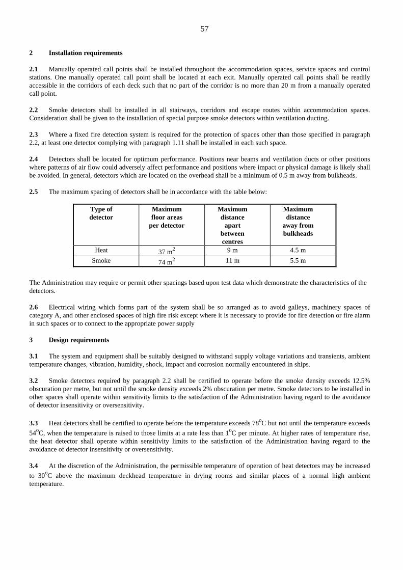
57
2 Installation requirements
2.1 Manually operated call points shall be installed throughout the accommodation spaces, service spaces and controlstations. One manually operated call point shall be located at each exit. Manually operated call points shall be readilyaccessible in the corridors of each deck such that no part of the corridor is no more than 20 m from a manually operatedcall point.
2.2 Smoke detectors shall be installed in all stairways, corridors and escape routes within accommodation spaces.Consideration shall be given to the installation of special purpose smoke detectors within ventilation ducting.
2.3 Where a fixed fire detection system is required for the protection of spaces other than those specified in paragraph2.2, at least one detector complying with paragraph 1.11 shall be installed in each such space.
2.4 Detectors shall be located for optimum performance. Positions near beams and ventilation ducts or other positionswhere patterns of air flow could adversely affect performance and positions where impact or physical damage is likely shallbe avoided. In general, detectors which are located on the overhead shall be a minimum of 0.5 m away from bulkheads.
2.5 The maximum spacing of detectors shall be in accordance with the table below:
Type ofdetector
Maximumfloor areas
per detector
Maximumdistance
apartbetweencentres
Maximumdistance
away frombulkheads
Heat 37 m2 9 m 4.5 m
Smoke 74 m2 11 m 5.5 m
The Administration may require or permit other spacings based upon test data which demonstrate the characteristics of thedetectors.
2.6 Electrical wiring which forms part of the system shall be so arranged as to avoid galleys, machinery spaces ofcategory A, and other enclosed spaces of high fire risk except where it is necessary to provide for fire detection or fire alarmin such spaces or to connect to the appropriate power supply
3 Design requirements
3.1 The system and equipment shall be suitably designed to withstand supply voltage variations and transients, ambienttemperature changes, vibration, humidity, shock, impact and corrosion normally encountered in ships.
3.2 Smoke detectors required by paragraph 2.2 shall be certified to operate before the smoke density exceeds 12.5%obscuration per metre, but not until the smoke density exceeds 2% obscuration per metre. Smoke detectors to be installed inother spaces shall operate within sensitivity limits to the satisfaction of the Administration having regard to the avoidanceof detector insensitivity or oversensitivity.
3.3 Heat detectors shall be certified to operate before the temperature exceeds 78oC but not until the temperature exceeds
54oC, when the temperature is raised to those limits at a rate less than 1oC per minute. At higher rates of temperature rise,the heat detector shall operate within sensitivity limits to the satisfaction of the Administration having regard to theavoidance of detector insensitivity or oversensitivity.
3.4 At the discretion of the Administration, the permissible temperature of operation of heat detectors may be increased
to 30oC above the maximum deckhead temperature in drying rooms and similar places of a normal high ambienttemperature.

58
5.12 If a system to monitor flammable atmospheres innon-cargo spaces is fitted, are recorders, alarms and themanufacturers test procedures in order?ISGOTT 7.8; 8.2; 18.5 SOLAS II-2 Reg. 13-1
ISGOTT 7.8 MONITORING OF VOID AND BALLAST SPACES
Void and ballast spaces located within the cargo tank block should be routinely monitored to check that no leakage hasoccurred from adjacent cargo tanks. Monitoring should include regular atmosphere checks for hydrocarbon content andregular sounding/dipping of the empty spaces.The guidance given in Chapter 8 ‘Double Hull Operations’ should be followed to the extent that it may apply to single hulltankers, particularly with regard to routine monitoring procedures (Section 8.2); actions to be taken in the event of cargoleakage being detected (Section 8.5) and the handling of ballast after a leak (Section 8.9)
ISGOTT 8.2 ROUTINE MONITORING OF DOUBLE HULL SPACES
Double hull spaces should be regularly monitored in order to check the integrity of the inner shell plating. This can beaccomplished by monitoring the ballast tank atmosphere for hydrocarbon gas, and by regular sounding/ullaging of ballasttanks. The sampling referred to in this section is for leak detection purposes only, and should not be used as the criteria fortank entry. Section 8.3 refers to the procedures relating to tank entry for double hull spaces.
The atmosphere in each double hull tank and double bottom tank should be monitored for hydrocarbon content:• • Regularly during the loaded passage.• • Prior to ballasting the tank following a period of heavy weather.• • After any unusual event or occurrence e.g. unexpected lists, unforeseen operational problems.
The atmosphere monitoring programme should ensure that each tank is monitored at least once per week during the loadedpassage. However, where ships are engaged on short haul voyages which make this impractical, visual inspection of thetanks or the ballast water is considered to be a suitable alternative measure.
The hydrocarbon measurements should be taken with a portable gas detector at designated sampling points using installedfixed lines or a portable sampling hose, or with a fixed gas detection system where one is installed.
Where fixed gas detection systems are installed, operators should develop procedures to ensure that tank atmospheres aremonitored on a regular basis. They should ensure that full operating, maintenance and fault detection instructions arereadily available to ship's personnel, and that they are familiar with the use of the equipment.
Information as to the point of origin of each fixed sampling line should be readily available to ship's personnel.
Procedures should be developed for the regular clearing of all fixed sampling lines.
The ship should be provided with information relating to any restrictions on lowering a sampling hose into the tank whichmight be imposed as a result of normal operating trim or list.
During the loaded passage, ballast tanks should be sounded on a frequent and regular basis as a back up method ofdetecting any oil leakage into them.
After ballasting, tanks should be checked visually to ascertain if any oil is present. A similar procedure should be carriedout prior to discharge of ballast.
During the ballast voyage, the usage of each ballast tank should be checked at frequent and regular intervals. Considerationshould also be given to the feasibility of routine monitoring to detect water ingress to the cargo tanks.
ISGOTT 18.5 FIXED FLAMMABLE GAS DETECTION INSTALLATIONS

59
Fixed installations have been employed to a limited extent in a few petroleum tankers to monitor the flammability of theatmosphere in spaces such as pipe tunnels in double bottoms and pump-rooms. Three general arrangements have beendeveloped for fixed monitoring, thus:
• A multiplicity of sensing devices is distributed throughout the spaces to be monitored. Signals are taken sequentiallyfrom them by a central control.
• A gas measurement system is installed in the central control room. Samples of the atmospheres to be checked aredrawn sequentially, usually by vacuum pump, through vacuum lines to the central gas measurement system. It is importantto ensure that there is no leakage of air into the system which would dilute the samples and cause misleading readings.
• Infra-red sensors are located in the space being monitored and the electronics necessary for processing the signalsare located in a safe location, usually the central control room.
SOLAS II-2 Regulation 13-1Sample extraction smoke detector systems
(This regulation applies to ships constructed on or after 1 February 1992)
1 General requirements
1.1 Wherever in the text of this regulation the word system appears, it shall mean sample extraction smoke detectionsystem.
1.2 Any required system shall be capable of continuous operation at all times except that systems operating on asequential scanning principle may be accepted, provided that the interval between scanning the same position twice givesan overall response time to the satisfaction of the Administration.
1.3 Power supplies necessary for the operation of the system shall be monitored for loss of power. Any loss of powershall initiate a visual and audible signal at the control panel and the navigating bridge which shall be distinct from a signalindicating smoke detection.
1.4 An alternative power supply for the electrical equipment used in the operation of the system shall be provided.
1.5 The control panel shall be located on the navigating bridge or in the main fire control station.
1.6 The detection of smoke or other products of combustion shall initiate a visual and audible signal at the control paneland the navigating bridge.
1.7 Clear information shall be displayed on or adjacent to the control panel designating the spaces covered.
1.8 The sampling pipe arrangements shall be such that the location of the fire can be readily identified.
1.9 Suitable instructions and component spares shall be provided for the testing and maintenance of the system.
1.10 The functioning of the system shall be periodically tested to the satisfaction of the Administration. The system shallbe of a type that can be tested for correct operation and restored to normal surveillance without the renewal of anycomponent.
1.11 The system shall be designed, constructed and installed so as to prevent the leakage of any toxic or flammablesubstances or fire -extinguishing media into any accommodation and service space, control station or machinery space.
2 Installation requirements
2.1 At least one smoke accumulator shall be located in every enclosed space for which smoke detection is required.However, where a space is designed to carry oil or refrigerated cargo alternatively with cargoes for which a smoke samplingsystem is required, means may be provided to isolate the smoke accumulators in such compartments for the system. Suchmeans shall be to the satisfaction of the Administration.

60
2.2 Smoke accumulators shall be located for optimum performance and shall be spaced so that no part of the overheaddeck area is more than 12 m measured horizontally from an accumulator. Where systems are used in spaces which may bemechanically ventilated, the position of the smoke accumulators shall be considered having regard to the effects ofventilation.
2.3 Smoke accumulators shall be positioned where impact or physical damage is unlikely to occur.
2.4 Not more than four accumulators shall be connected to each sampling point.
2.5 Smoke accumulators from more than one enclosed space shall not be connected to the same sampling point.
2.6 Sampling pipes shall be self-draining and protected from impact or damage from cargo working.
3 Design requirements
3.1 The system and equipment shall be suitably designed to withstand supply voltage variations and transients, ambienttemperature changes, vibration, humidity, shock, impact and corrosion normally encountered in ships and to avoid thepossibility of ignition of flammable gas air mixture.
3.2 The sensing unit shall be certified to operate before the smoke density within the sensing chamber exceeds 6.65%obscuration per metre.
3.3 Duplicate sample extraction fans shall be provided. The fans shall be of sufficient capacity to operate with thenormal conditions or ventilation in the protected area and shall give an overall response time to the satisfaction of theAdministration.
3.4 The control panel shall permit observation of smoke in the individual sampling pipe.
3.5 Means shall be provided to monitor the airflow through the sampling pipes so designed as to ensure that as far aspracticable equal quantities are extracted from each interconnected accumulator.
3.6 Sampling pipes shall be a minimum of 12 mm internal diameter except when used in conjunction with fixed gasfire-extinguishing systems when the minimum size of pipe should be sufficient to permit the fire-extinguishing gas to bedischarged within the appropriate time.
3.7 Sampling pipes shall be provided with an arrangement for periodically purging with compressed air.
5.13 Are the emergency towing off wires (fire wires) insatisfactory condition?OCIMF Mooring Equipment Guidelines. Section 3.11
3.11 FIRE WIRES
Terminals require the provision of so-called 'fire-wires' or 'towing-off wires'. These are mooring wires hung over the off-berth side of the ship. They enable tugs to pull the ship away from the pier without the assistance of any crew member incase of a serious fire or explosion. Refer also to Reference 6 ("International Safety Guide for Oil Tankers and Terminals",4th edition, 1996), Chapter 3.7.2. (See Ref. 5.14)
A common method is to provide two wires, one near the bow and one near the stern. They are secured to bollards with aminimum of five turns and are led directly to a shipside chock with no slack on deck. The outboard end of the line isprovided with an eye to which a heaving line is attached and led back to the deck;. During loading or discharge, theheaving line is periodically adjusted to maintain the eye of the fire wire one to two metres above the water as shown inFigure 3.15. (Refer to document) Some terminals require different methods and operators should be aware of localregulations.
When not in use, the wires are preferably spooled onto reels which may be located on or below deck.

61
Fire wires should be of 6 x 36 IWRC construction and be made of the same type of steel as recommended for standardmooring wires in Section 6. The use of synthetic or natural fibre ropes is not permitted as these would burn in the event of afire.
The following table gives guidance on minimum diameters and lengths for various ship sizes, however, lengths may varydependent on positioning of mooring bitts and vessel's freeboard.
kDWT Diameter (mm) Length (m)20-100 28 45100-300 38 60over 300 42 70
5.14 Are the emergency towing off wires (fire wires)properly rigged to meet terminal requirements?OCIMF Mooring Equipment Guidelines. Section 3.11ISGOTT 3.7.2
Mooring Equipment Guidelines. Section 3.11
See 5.13
ISGOTT 3.7 EMERGENCY RELEASE PROCEDURES
3.7.2 Emergency Towing Off Wires (Fire Wires)
Except at terminals where no tugs are available, towing off wires of adequate strength and condition should be made fast tobollards on the tanker, forward and aft, and their eyes run out and maintained at, or about, the waterline.
On tankers alongside a jetty, the fire wires should be hung in positions which tugs can reach without difficulty, usually theoffshore side; for tankers at buoy berths, they should be hung on the side opposite to the hose strings.
In order that sufficient wire can pay out to enable the tugs to tow effectively, enough slack should be retained between thebollard and the fairlead and be prevented from running out by a rope yarn, or other easily broken means.
There are various methods for rigging emergency towing wires currently in use and the arrangement may vary from port toport. Some terminals may require a particular method to be used and the ship should be advised accordingly,
5.15 Are ship specific SOLAS Training and Maintenancemanuals for lifesaving appliances on board?SOLAS III–B Reg.35
Regulation 35Training manual and on-board training aids
1 This regulation applies to all ships.2 A training manual complying with the requirements of paragraph 3 shall be provided in each crew mess roomand recreation room or in each crew cabin.3 The training manual, which may comprise several volumes, shall contain instructions and information, in easilyunderstood such information may be provided in the form of audio-visual aids in lieu of the manual. The following shall beexplained in detail:

62
.1 donning of lifejackets, immersion suits, and anti-exposure suits as appropriate;
.2 muster at the assigned stations;
.3 boarding, launching, and clearing the survival craft and rescue boats, including, where applicable, use ofmarine evacuation systems;
.4 method of launching from within the survival craft;
.5 release from launching appliances;
.6 methods and use of devices for protection in launching areas, where appropriate;
.7 illumination in the launching areas;
.8 use of all survival equipment;
.9 use of all detection equipment;
.10 with the assistance of illustrations. the use of the radio life-saving appliances;
.11 use of drogues;
.12 use of engine and accessories;
.13 recovery of survival craft and rescue boats including stowage and securing;
.14 hazards of exposure and the need for warm clothing;
.15 best use of the survival craft facilities in order to survive;
.16 methods of retrieval, including use of helicopter rescue gear (slings, baskets, stretchers), breeches buoy andshore life-saving apparatus and ship's line throwing apparatus.
.17 all other functions contained in the muster list and emergency instructions; and,
.18 instructions for emergency repair of the lifesaving appliances.
4 Every ship fitted with a marine evacuation system shall be provided with on-board training aids in the use of thesystem.
5.16 Are all lifesaving appliances in a satisfactorycondition?
5.16.1 Are lifeboats, including equipment and lowering mechanisms, and liferafts, in a satisfactorycondition?SOLAS III-B Reg. 31
Regulation 31Survival craft and rescue boats
1 Survival craft
1.1 Cargo ships shall carry:
.1 one or more totally enclosed lifeboats complying with the requirements of section 4.6 of the Code of suchaggregate capacity on each side of the ship as will accommodate the total number of persons on board; and
.2 in addition, one or more inflatable or rigid liferafts, complying with the requirements of section 4.2 or 4.3 ofthe Code, stowed in a position providing for easy side-to-side transfer at a single open deck level, and of suchaggregate capacity as will accommodate the total number of persons on board. If the liferaft or liferafts arenot stowed in a position providing for easy side-to-side transfer at a single open deck level, the total capacityavailable on each side shall be sufficient to accommodate the total number of persons on board.
1.2 In lieu of meeting the requirements of paragraph 1.1, cargo ships may carry:
.1 one or more free-fall lifeboats, complying with the requirements of section 4.7 of the Code, capable of beingfree-fall launched over the stem of the ship of such aggregate capacity as will accommodate the total numberof persons on board; and

63
.2 in addition, one or more inflatable or rigid liferafts complying with the requirements of section 4.2 or 4.3 ofthe Code, on each side of the ship, of such aggregate capacity as will accommodate the total number ofpersons on board. The liferafts on at least one side of the ship shall be served by launching appliances.
1.3 In lieu of meeting the requirements of paragraph 1.1 or 1.2, cargo ships of less than 85 m in length other thanoil tankers, chemical tankers and gas carriers, may comply with the following:
.1 they shall carry on each side of the ship, one or more inflatable or rigid liferafts complying with therequirements of section 4.2 or 4.3 of the Code and of such aggregate capacity as will accommodate the totalnumber of persons on board;
.2 unless the liferafts required by paragraph 1.3.1 are stowed in a position providing for easy side-to-sidetransfer at a single open deck level, additional liferafts shall be provided so that the total capacity available oneach side will accommodate 1500/0 of the total number of persons on board;
.3 if the rescue boat required by paragraph 2 is also a totally enclosed lifeboat complying with the requirementsof section 4.6 of the Code, it may be included in the aggregate capacity required by paragraph 1.3.1, providedthat the total capacity available on either side of the ship is at least 150% of the total number of persons onboard; and
.4 in the event of any one survival craft being lost or rendered unserviceable, there shall be sufficient survivalcraft available for use on each side, including any which are stowed in a position providing for easy side-to-side transfer at a single open deck level, to accommodate the total number of persons on board.
1.4 Cargo ships where the horizontal distance from the extreme end of the stem or stern of the ship to the nearest end ofthe closest survival craft is more than 100 m shall carry, in addition to the liferafts required by paragraphs 1.1.2 and 1.2.2,a liferaft stowed as far forward or aft, or one as far forward and another as far aft, as is reasonable and practicable. Suchliferaft or liferafts may be securely fastened so as to permit manual release and need not be of the type which can belaunched from an approved launching device.
1.5 With the exception of the survival craft referred to in regulation 16.1.1, all survival craft required to provide forabandonment by the total number of persons on board shall be capable of being launched with their full complement ofpersons and equipment within a period of 10 min from the time the abandon ship signal is given.
1.6 Chemical tankers and gas carriers carrying cargoes emitting toxic vapours or gases* shall carry, in lieu of totallyenclosed lifeboats complying with the requirements of section 4.6 of the Code, lifeboats with a self-contained air supportsystem complying with the requirements of section 4.8 of the Code.
1.7 Oil tankers, chemical tankers and gas carriers carrying cargoes having a flashpoint not exceeding 60oC (closed-cuptest) shall carry, in lieu of totally enclosed lifeboats complying with the requirements of section 4.6 of the Code, fire-protected lifeboats complying with the requirements of section 4.9 of the Code.
2 Rescue boats
Cargo ships shall carry at least one rescue boat complying with the requirements of section 5.1 of the Code. A lifeboat maybe accepted as a rescue boat, provided that it also complies with the requirements for a rescue boat.
3 In addition to their lifeboats, all cargo ships constructed before 1 July 1986 shall carry:
.1 one or more liferafts capable of being launched on either side of the ship and of such aggregate capacity aswill accommodate the total number of persons on board. The liferaft or liferafts shall be equipped with alashing or an equivalent means of securing the liferaft which will automatically release it from a sinkingship; and
.2 where the horizontal distance from the extreme end of the stem or stem of the ship to the nearest end of theclosest survival craft is more than 100 ra, in addition to the liferafts required by paragraph 3.1, a liferaftstowed as far forward or aft, or one as far forward and another as far aft, as is reasonable and practicable.Notwithstanding the requirements of paragraph 3.1, such liferaft or liferafts may be securely fastened so asto permit manual release.

64
*Refer to the products for which emergency escape respiratory protection is required in chapter 17 of the International Codefor the Construction and Equipment of Ships Carrying Dangerous Chemicals in Bulk (IBC Code), adopted by the MaritimeSafety Committee by resolution MSC.4(48), and in chapter 19 of the International Code for the Construction andEquipment of Ships Carrying Liquefied Gases in Bulk (IGC Code), adopted by the Maritime Safety Committee byresolution MSC.5(48).
5.16.2 Are hydrostatic releases, if fitted to liferafts, correctly attached, in satisfactory condition,and is servicing in date?
SOLAS III-B Reg. 13; LSA Code 4.1.6
Regulation 13Stowage of survival craft
1 Each survival craft shall be stowed:
.1 so that neither the survival craft nor its stowage arrangements will interfere with the operation of any other survivalcraft or rescue boat at any other launching station;
.2 as near the water surface as is safe and practicable and. iii the case of a survival craft other than a liferaft intendedfor throw over board launching, in such a position that the survival craft in the embarkation position is not less than2 m above the waterline with the ship in the fully loaded condition under unfavourable conditions of trim of Lip to10o and listed up to 20o either way, or to the angle at which the ship's weather deck edge becomes submerged,whichever is less;
.3 in a state of continuous readiness so that two crew members can carry out preparations for embarkation andlaunching in less than 5 min;
.4 fully equipped as required by this chapter and the Code; and
.5 as far as practicable, in a secure and sheltered position and protected from damage by tire and explosion. Inparticular, survival craft on tankers, other than the liferafts required by regulation 31.1.4, shall not be stowed on orabove a cargo tank, slop tank, or other tank containing explosive or hazardous cargoes.
2 Lifeboats for lowering down the ship's side shall be stowed as far forward of the propeller as practicable. On cargoships of 8Om in length and upwards but less than 120 m in length, each lifeboat shall be so stowed that the after end of thelifeboat is not less than the length of the lifeboat forward of the propeller. On cargo ships of 120 m in length and upwardsand passenger ships of 80 m in length and upwards, each lifeboat shall be so stowed that the after end of the lifeboat is notless than 1.5 times the length of the lifeboat forward of the propeller. Where appropriate, the ship shall be so arranged thatlifeboats, in their stowed positions, are protected from damage by heavy seas.
3 Lifeboats shall be stowed attached to launching appliances.
4.1 Every liferaft shall be stowed with its painter permanently attached to the ship.
4.2 Each liferaft or group of liferafts shall be stowed with a float-free arrangement complying with the requirements ofparagraph 4.1.6 of the Code so that each floats free and, if inflatable, inflates automatically when the ship sinks.
4.3 Liferafts shall be so stowed as to permit manual release of one raft or container at a time from their securingarrangements.
4.4 Paragraphs 4.4 and 4.2 do not apply to liferafts required by regulation 34.1.4.
5 Davit-launched liferafts shall be stowed within reach of the lifting hooks, unless some means of transfer is providedwhich is not rendered inoperable within the limits of trim and list prescribed in paragraph 1.2 or by ship motion or powerfailure.
6 Liferafts intended for throw-overboard launching shall be so stowed as to be readily transferable for launching oneither side of the ship unless liferafts, of the aggregate capacity required by regulation 31.1 to be capable of being launchedon either side, are stowed on each side of the ship.

65
LSA Code 4.1.64.1.6 Float-free arrangements for liferafts
4.1.6.1 Painter system
The liferaft painter system shall provide a connection between the ship and the liferaft and shall be so arranged as to ensurethat the liferaft when released and, in the case of an inflatable liferaft, inflated is not dragged under by the sinking ship.
4.1.6.2 Weak link
If a weak link is used in the float-free arrangement, it shall:.1 not be broken by the force required to put the painter from the liferaft container;.2 if applicable, be of sufficient strength to permit the inflation of the liferaft; and.3 break under a strain of 2.2 ± 0.4 kN.
4.1.6.3 Hydrostatic release units
If a hydrostatic release unit is used in the float-free arrangements, it shall:
.1 be constructed of compatible materials so as to prevent malfunction of the unit. Galvanizing or other forms ofmetallic coating on parts of the hydrostatic release unit shall not be accepted;
.2 automatically release the liferaft at a depth of not more than 4 m;
.3 have drains to prevent the accumulation of water in the hydrostatic chamber when the unit is in its normalposition;
.4 be so constructed as to prevent release when seas wash over the unit;
.5 be permanently marked on its exterior with its type and serial number;
.6 be permanently marked, on the unit or identification plate securely attached to the unit, with the date ofmanufacture, type and serial number and whether the unit is suitable for use with a liferaft with a capacity ofmore than 25 persons;
.7 be such that each part connected to the painter system has a strength of not less than that required for thepainter; and
.8 if disposable, in lieu of the requirement in paragraph 4.1.6.3.6, be marked with a means of determining itsdate of expiry.
5.16.3 Are survival craft portable VHF radios and Search and Rescue Radar Transponders(SARTS) in satisfactory condition and charged?
SOLAS III-B Reg. 6.2.2
6.2.2 Radar transponders
At least one radar transponder shall be carried on each side of every passenger ship and of every cargo ship of 500 grosstonnage and upwards. At least one radar transponder shall be carried on every cargo ship of 300 gross tonnage and upwardsbut less than 500 gross tonnage. Such radar transponders shall conform to performance standards not inferior to thoseadopted by the Organization. The radar transponders: shall be stowed in such locations that they can be rapidly placed inany survival craft other than the liferaft or liferafts required by regulation 31.1.4. Alternatively one radar transponder shallbe stowed in each survival craft other than those required by regulation 31.1.4. On ships carrying at least two radartransponders and equipped with free-fall lifeboats one of the radar transponders shall be stowed in a free-fall lifeboat andthe other located in the immediate vicinity of the navigation bridge so that it can be utilised on board and ready for transferto any of the other survival craft.

66
5.16.4 Are lifeboat and liferaft operating instructions displayed?SOLAS III-B Reg. 9
Regulation 9Operating Instructions
1 This regulation applies to all ships.2 Posters or signs shall be provided on or in the vicinity of survival craft and their launching controls and shall:
.1 illustrate the purpose of controls and the procedures for operating the appliance and give relevant instructionsor warnings;
.2 be easily seen under emergency lighting conditions; and
.3 use symbols in accordance with the recommendations of the Organization*
*Refer to the Symbols related to lifesaving appliances and arrangements adopted by the Organization by Resolution A760(18)
5.16.5 Are lifebuoys, lifebuoy lights, quick release mechanisms and self-activating smoke floatsin a satisfactory condition?SOLAS III-B Reg. 7, 32
Regulation 7Personal life-saving appliances
1 Lifebuoys
1.1 Lifebuoys complying with the requirements of paragraph 2.1.1 of the Code shall be:
.1 so distributed as to be readily available on both sides of the ship and as far as practicable on all open decksextending to the ship's side; at least one shall be placed in the vicinity of the stern; and
.2 so stowed as to be capable of being rapidly cast loose, and not permanently secured in any way.
1.2 At least one lifebuoy on each side of the ship shall be fitted with a buoyant lifeline complying with therequirements of paragraph 2.1.4 of the Code equal in length to not less than twice the height at which it is stowed above thewaterline in the lightest seagoing condition, or 30 m, whichever is the greater.
1.3 Not less than one half of the total number of lifebuoys shall be provided with lifebuoy self-igniting lightscomplying with the requirements of paragraph 2.1.2 of the Code; not less than two of these shall also be provided withlifebuoy self-activating smoke signals complying with the requirements of paragraph 2.1.3 of the Code and be capable ofquick release from the navigation bridge; lifebuoys with lights and those with lights and smoke signals shall be equallydistributed on both sides of the ship and shall not be the lifebuoys provided with lifelines in compliance with therequirements of paragraph 1.2.
l.4 Each lifebuoy shall be marked in block capitals of the Roman alphabet with the name and port of registry of theship on which it is carried.
2 Lifejackets
2.1 A lifejacket complying with the requirements of paragraph 2.2.1 or 2.22 of the Code shall be provided for everyperson on board the ship and, in addition:
.1 a number of lifejackets suitable for children equal to at least 1O% of the number of passengers on board shallbe provided or such greater number as may be required to provide a lifejacket for each child; and

67
.2 a sufficient number of lifejackets shall be carried for persons on watch and for use at remotely locatedsurvival craft stations. The lifejackets carried for persons on watch should be stowed on the bridge, in theengine control room and at any other manned watch station.
2.2 Lifejackets shall be so placed as to be readily accessible and their position shall be plainly indicated. Where, due tothe particular arrangements of the ship, the lifejackets provided in compliance with the requirements of paragraph 2.1 maybecome inaccessible, alternative provisions shall be made to the satisfaction of the Administration which may include anincrease in the number of lifejackets to be carried.
2.3 The lifejackets used in totally enclosed lifeboats, except free-fall lifeboats, shall not impede entry into the lifeboator seating, including operation of the seat belts in the lifeboat.
2.4 Lifejackets selected for free-fall lifeboats, and the manner in which they are carried or worn, shall not interferewith entry into the lifeboat, occupant safety or operation of the lifeboat.
3 Immersion suits and anti-exposure suits
An immersion suit, complying with the requirements of section 2.3 of the Code or an anti-exposure suit complying withsection 2.4 of the Code, of an appropriate size, shall be provided for every person assigned to crew the rescue boat orassigned to the marine evacuation system party. If the ship is constantly engaged in warm climates where, in the opinion ofthe Administration thermal protection is unnecessary, this protective clothing need not be carried.
Regulation 32
Refer to document
5.16.6 Are pyrotechnics, including line throwing apparatus, in date and in a satisfactorycondition?
SOLAS III-B Regs. 6.3; 18; SOLAS V Reg. 16
SOLAS III-B Regulation 6Communications
6.3 Distress flares
Not less than 12 rocket parachute flares, complying with the requirements of 3.1 of the Code, shall be carried on or near thenavigation bridge
Regulation 18Line throwing appliance
A line throwing appliance complying with the requirements of section 7.1 of the Code shall be provided.
SOLAS V Regulation 16Life-saving signals
Life-saving signals* shall be used by life-saving stations, maritime rescue units and aircraft engaged in search and rescueoperations when communicating with ships or persons in distress or to direct ships, and by ships or persons in distresswhen communicating with life saving stations, maritime rescue units and aircraft engaged in search and rescue operations.An illustrated table describing the life-saving signals shall be readily available to the officer of the watch of every ship towhich this chapter applies.

68
5.16.7 Is oxygen resuscitation equipment available?ISGOTT 11.8
11.8 RESUSCITATION
All terminal and tanker personnel should be instructed in resuscitation techniques for the treatment of persons who havebeen overcome by toxic gases or fumes, or whose breathing has stopped from other causes such as electric shock ordrowning.
Most tankers and terminals are provided with special apparatus for use in resuscitation. This apparatus can be of a numberof different types. It is important that personnel are aware of its presence and are trained in its proper use.
The apparatus should be stowed where it is easily accessible and not kept locked up. The instructions provided with itshould be clearly displayed on board ship. The apparatus and the contents of cylinders should be checked periodically.Adequate spare bottles should be carried.
5.16.10 Is there a maintenance schedule in place for the servicing of lifeboat on-load release gearand is it subjected to thorough examination and test carried out at least once every fiveyears?
SOLAS III-B Reg. 20; IMO MSC Circ.614 (29/6/93)
Regulation 20Operational readiness, maintenance and inspections
1 This regulation applies to all ships. The requirements of paragraphs 3 and 6.2 shall be complied with, as far asis practicable, on ships constructed before 1 July 1986.
2 Operational readiness
Before the ship leaves port and at all times during the voyage, all lifesaving appliances shall be in working order and readyfor immediate use.
3 Maintenance
3.1 Instructions for on-board maintenance of life-saving appliances complying with the requirements of regulation36 shall be provided and maintenance shall be carried out accordingly.
3.2 The Administration may accept, in lieu of the instructions required by paragraph 3.1, a shipboard plannedmaintenance programme which includes the requirements of regulation 36.
4 Maintenance of falls
4.1 Falls used in launching shall be turned end for end at intervals of not more than 30 months and be renewedwhen necessary due to deterioration of the falls or at intervals of not more than five years, whichever is theearlier.
4.2 The Administration may accept in lieu of the “end for ending" required in paragraph 4.1, periodic inspection ofthe falls and their renewal whenever necessary due to deterioration or at intervals of not more than four years,whichever one is earlier.
5 Spares and repair equipment
Spares and repair equipment shall be provided for lifesaving appliances and their components which are subject toexcessive wear or consumption and need to be replaced regularly.

69
6 Weekly inspection
The following tests and inspections shall be carried out weekly:
.1 all survival craft, rescue boats and launching appliances shall be visually inspected to ensure that they areready for use;
.2 all engines in lifeboats and rescue boats shall be run for a total period of not less than 3 min provided theambient temperature is above the minimum temperature required for starting and running the engine.During this period of time, it should be demonstrated that the gear box and gear box train are engagingsatisfactorily. If the special characteristics of an outboard motor fitted to a rescue boat would not allow it tobe run other than with its propeller submerged for a period of 3 min, it should be run for such period asprescribed in the manufacturer's handbook.
In special cases the Administration may waive this requirement for ships constructed before 1 July 1986; and
.3 the general emergency alarm system shall be tested.
7 Monthly inspections
Inspection of the life-saving appliances, including lifeboat equipment, shall be carried out monthly using the checklistrequired by regulation 36.1 to ensure that they are complete and in good order. A report of the inspection shall be entered inthe log-book.
8 Servicing of inflatable liferafts, inflatable lifejackets, marine evacuation systems, and inflated rescue boats.
8.1 Every inflatable liferaft, inflatable lifejacket, and marine evacuation system shall be serviced:
.1 at intervals not exceeding 12 months, provided where in any case this is impracticable, the Administration mayextend this period to 1 7 months; and
.2 at an approved servicing station which is competent to service them, maintains proper servicing facilities anduses only properly trained personnel.*
8.2 Rotational dep1oymennt of marine evacuation systems
In addition to or in conjunction with the servicing intervals of marine evacuation systems required by paragraph 8.1, eachmarine evacuation system should be deployed from the ship on a rotational basis at intervals to be agreed by theAdministration provided that each system is to be deployed at least once every six years.
8.3 An Administration which approves new and novel inflatable liferaft arrangements pursuant to regulation 4 may allowfor extended service intervals on the following conditions:
8.3.1 The new and novel liferaft arrangement has proved to maintain the same standard, as required by testing procedure,during extended service intervals.
8.3.2 The liferaft system shall be checked on board by certified personnel according to paragraph 8.1.1.
8.3.3 Service at intervals not exceeding five years shall be carried out in accordance with the recommendations of theOrganization. *
8.4 All repairs and maintenance of inflated rescue boats shall be carried out in accordance with the manufacturer'sinstructions. Emergency repairs may be carried out on board the ship; however, permanent repairs shall be effected at anapproved servicing station.
8.5 An Administration which permits extension of liferaft service intervals in accordance with paragraph 8.3 shall notifythe Organization of such action in accordance with regulation 1/5(b).

70
9 Periodic servicing of hydrostatic release units
Hydrostatic release units, other than disposable hydrostatic release units, shall be serviced:
.1 at intervals not exceeding 12 months, provided where in any case this is impracticable, the Administration mayextend this period to 17 months; and
.2 at a servicing station which is competent to service them, maintains proper servicing facilities and uses onlyproperly trained personnel.
10 Marking of stowage locations
Containers, brackets, racks, and other similar stowage locations for life-saving equipment shall be marked with symbols inaccordance with the recommendations of the Organization** indicating the devices stowed in that location for that purpose.If more than one device is stowed in that location, the number of devices shall also be indicated.
11 Periodic servicing of launching appliances and on-load release gear
11.1 Launching appliances:
.1 shall be serviced at recommended intervals in accordance with instructions for on-board maintenance asrequired by regulation 36;
.2 shall be subjected to a thorough examination at intervals not exceeding 5 years; and
.3 shall upon completion of the examination in .2 be subjected to a dynamic test of the winch brake in accordancewith paragraph 6.1.2.5.2 of the Code.
11.2 Lifeboat on-load release gear shall be:
.1 serviced at recommended intervals in accordance with instructions for on board maintenance as required byregulation 36;
.2 subjected to a thorough examination and test during the surveys required by regulation 1/7 and 1/8 by properlytrained personnel familiar with the system; and
.3 operationally tested under a load of 1.1 times the total mass of the lifeboat when loaded with its fullcomplement of persons and equipment whenever the release gear is overhauled. Such overhauling and test shallbe carried out at least once every five years.***
*Refer to the recommendation on conditions for the approval of servicing stations for inflatable liferafts adopted by theOrganization by resolution A.761(18)**Refer to the Symbols related to 1ifesaving appliances and arrangements adopted by the Organization by resolutionA.760( 18).***Refer to the recommendation on testing of life-saving appliances adopted by the Organization by resolution A.689(17)as it may be amended.
IMO MSC Circ.614 (29/6/93)
Refer to document
5.17 Are lifeboat drills held in accordance with SOLASrequirements?Ref: SOLAS Ch.III-B Reg.19.3
SOLAS III-B Reg.19.3.3Abandon ship drill
19.3.3 Each abandon ship drill shall include:

71
.1 summoning of passengers and crew to muster stations with the alarm required by Regulation 6.4.2 followed bydrill announcement on the public address or other communication system and ensuring that they are madeaware of the order to abandon ship;
.2 reporting to stations and preparing for the duties prescribed in the muster list; .3 checking that passengers and crew are suitably dressed; .4 checking that lifejackets are correctly donned; .5 lowering of at least one lifeboat and any necessary preparation for launching; .6 starting and operating the lifeboat engine; .7 operation of davits used for launching liferafts; .8 a mock search and rescue of passengers trapped in their staterooms; and, .9 instructions in the used of radio life-saving appliances.
3.3.2 Different lifeboats shall, as far as practicable, be lowered in compliance with the requirements of paragraph 3.3.1.5at successive drills.3.3.3 Except as provided in paragraph 3.3.4 and 3.3.5, each lifeboat shall be launched with its assigned operating crewaboard and manoeuvred in the water at least once every three months during an abandon ship drill.3.3.4 Lowering into the water, rather than launching of a lifeboat arranged for free-fall launching, is acceptable wherefree-fall launching is impracticable provided the lifeboat is free-fall launched with its assigned operating crew aboard andmanoeuvred in the water at least once every six months. However, in cases where it is impracticable, the Administrationmay extend this period to twelve months provided that arrangements are made for simulated launching which will takeplace at intervals not more than six months.3.3.5 The Administration may allow ships operating on short international voyages not to launch the lifeboats on one sideif their berthing arrangements in port and their trading patterns do not permit launching of lifeboats on that side. However,all such lifeboats shall be lowered at least once every three months and launched at least annually.3.3.6 As far as is reasonable and practicable, rescue boats other than lifeboats which are also rescue boats, shall belaunched each month with their assigned crew aboard and manoeuvred in the water. In all cases this requirement shall becomplied with at least once every three months.3.3.7 If lifeboat and rescue boat launching drills are carried out with the ship making headway, such drills shall, becauseof the dangers involved, be practiced in sheltered waters only and under the supervision of an officer experienced in suchdrills.3.3.8 If a ship is fitted with marine evacuation systems, drills shall include exercising of the procedures required for thedeployment of such a system up to a point immediately preceding actual deployment of the system. This aspect of drillsshould be augmented by regular instruction using the on-board training aids required by Regulation 35.4. Additionallyevery system party member shall, as far as practicable, be further trained by participation of full deployment of a similarsystem into the water, either on board a ship or ashore, at intervals of not longer than two years, but in no case longer thanthree years. This training can be associated with the deployment required by regulation 20.8.23.3.9 Emergency lighting for mustering and abandonment shall be tested at each abandon ship drill.

72
6. POLLUTION PREVENTION
6.1 Is an approved MARPOL Shipboard Oil PollutionEmergency Response Plan (SOPEP) on board and aredrills regularly held and recorded?MARPOL 73/78 Annex I Ch.IV Reg. 26
Prevention of pollution arising from an oil pollution incident*Reg. 26Shipboard oil pollution emergency plan
(1) Every oil tanker of 150 tons gross tonnage and above and every other ship other than an oil tanker of 400 tons grosstonnage and above shall carry on board a shipboard oil pollution emergency plan approved by the Administration. In thecase of ships built before 4 April 1993 this requirement shall apply 24 months after that date.
(2) Such a plan shall be in accordance with guidelines* developed by the Organisation and written in the workinglanguage of the master and the officers. The plan shall consist at least of:
(a) the procedure to be followed by the master or other person having charge of the ship to report an oil pollutionincident as required in article 8 and Protocol I of the present Convention, based on the guidelines developed by theOrganisation;**
(b) the list of authorities or persons to be contacted in the event of an oil pollution incident;
(c) a detailed description of the action to be taken immediately by persons on board to reduce or control the discharge ofoil following the incident; and
(d) the procedures and point of contact on the ship for co-ordinating shipboard action with national and local authoritiesin combating the pollution
* Reference is made to "Guidelines for the development of shipboard oil pollution emergency plans" to be developedby the Organisation.** Reference is made to General Principles for Ship Reporting Systems and Ship Reporting Requirements, includingGuidelines for Reporting Incidents Involving Dangerous Goods, Harmful Substances and/or Marine Pollutants adopted bythe Organisation by resolution A.648(16)
6.4.1 Are anti-pollution warning notices posted?USCG 33 CFR 151, 155
Refer to documents
6.4.2 Are cargo sea and overboard valves, and bilge overboard valves suitably lashed or locked?ISGOTT 6.9.2
73
ISGOTT 6.9.2 Sea and Overboard Discharge Valves
At the start of and at regular intervals throughout loading, discharging, ballasting, and tank washing a watch should bekept to ensure that oil is not escaping through sea valves.
When not in use, sea and overboard discharge valves connected to the cargo and ballast systems must be securely closedand lashed and may be sealed. In-line blanks should be inserted where provided. When lashing is not practical, as withhydraulic valves, some suitable means of marking should be used to indicate clearly that the valves are to remain closed.
For further information on this subject reference should be made to the ICS/OCIMF publication 'Prevention of Oil Spillagesthrough Cargo Pumproom Sea Valves'.
6.5 Is there an approved Oil Discharge Monitoring andControl System (ODME) on board and is it in a satisfactorycondition?MARPOL 73/78 Annex I Regs. 15(3),(5); 16
MARPOL 73/78 Annex I Regulation 15Retention of Oil on Board
(3)(a) An oil discharge monitoring and control system approved by the Administration shall be fitted. In considering thedesign of the oil content meter to be incorporated in the system, the Administration shall have regard to the specificationrecommended by the Organisation.* The system shall be fitted with a recording device to provide a continuous record ofthe discharge in litres per nautical mile and total quantity discharged, or the oil content and rate of discharge. This recordshall be identifiable as to time and date and shall be kept for at least three years. The oil discharge monitor and controlsystem shall come into operation when there is any discharge of effluent into the sea and shall be such as will ensure thatany discharge of oily mixture is automatically stopped when the instantaneous rate of discharge of oil exceeds thatpermitted by regulation 9(1)(a) of this Annex. Any failure of this monitoring and control system shall stop the dischargeand be noted in the Oil Record Book. A manually operated alternative method shall be provided and may be used in theevent of such failure, but the defective unit shall be made operable as soon as possible. **The Port State authority mayallow the tanker with a defective unit to undertake one ballast voyage before proceeding to a repair port. The oil dischargemonitoring and control system shall be designed and installed in compliance with the Guidelines and Specifications for OilDischarge Monitoring and Control Systems for Oil Tankers developed by the Organisation. ***Administrations mayaccept such specific arrangements as detailed in the Guidelines and Specifications.
(b) Effective oil/water interface detectors approved by the Administration shall be provided for a rapid and accuratedetermination of the oil/water interface in slop tanks and shall be available for use in other tanks where the separation of oiland water is effected from which it is intended to discharge effluent direct to the sea.
(c) Instructions as to the operation of the system shall be in accordance with an operational manual approved by theAdministration. They shall cover manual as well as automatic operations and shall be intended to ensure that at no timeshall oil be discharged except in compliance with the conditions specified in Regulation 9 of this Annex.*
* Reference is made to the Recommendations on International Performance and Test Specifications for Oily WaterSeparating Equipment and Oil Content Meters adopted by the Organisation by resolution A.(393(X)** This amendment was adopted by the MEPC at its thirty-first session and will enter into force on 4 April 1993*** Reference is made to the revised Guidelines and Specifications for Oil Discharge Monitoring and Control Systems forOil Tankers adopted by the Organisation by resolution A.586(14)
(5)(a) The Administration may waive the requirements of paragraphs (1), (2) and (3) of this regulation for any oil tankerwhich engages exclusively on voyages both of 72 hours or less in duration and within 50 miles from the nearest land,provided that the oil tanker is engaged exclusively in trades between ports and terminals within a State Party to the presentConvention. Any such waiver shall be subject to the requirement that the oil tanker shall retain on board all oily mixturesfor subsequent discharge to reception facilities and to the determination by the Administration that facilities available toreceive such oily mixtures are adequate.

74
(b) The Administration may waive the requirement of paragraph (3) of this regulation for oil tankers other than thosereferred to in sub-paragraph (a) of this paragraph in cases where:
(i) the tanker is an existing tanker of 40,000 tons deadweight or above, as referred to in regulation 13C(1) of thisAnnex, engaged in specific trades, and the conditions specified in regulation 13C(2) are complied with; or,(ii) the tanker is engaged exclusively in one or more of the following categories of voyages:
(1) voyages within special areas; or(2) voyages within 50 miles from the nearest land outside special areas where the tanker is engaged in:(aa) trades between ports and terminals of a State Party to the present Convention; or(bb) restricted voyages as determined by the Administration, and of 72 hours or less in duration; provided that all of thefollowing conditions are complied with:(3) all oily mixtures are retained on board for subsequent discharge to reception facilities:
MARPOL 73/78 Annex I Regulation 16Oil discharge monitoring and control system and oil filtering equipment
(1) Any ship of 400 tons gross tonnage but less than 10,000 tons gross tonnage shall be fitted with oil filteringequipment complying with paragraph (4) of this regulation. Any such ship which carries large quantities of oil fuel shallcomply with paragraph (2) of this regulation or paragraph (1) of regulation 14
(2) Any ship of 10,000 tons gross tonnage and above shall be provided with oil filtering equipment, and witharrangements for an alarm and for automatically stopping any discharge of oily mixture when the oil content in the effluentexceeds 15 parts per million.
(3) (a) The Administration may waive the requirements of paragraph (1) and (2) of this regulation for any shipengaged exclusively on voyages within special areas provided that all the following conditions are complied with:
(i) the ship is fitted with a holding tank having a volume adequate, to the satisfaction of the Administration, for thetotal retention on board of the oily bilge water;(ii) all oily bilge water is retained on board for subsequent discharge to reception facilities;(iii) the Administration has determined that adequate reception facilities are available to receive such oily bilge water ina sufficient number of ports or terminals the ship calls at;(iv) the International Oil Pollution Prevention Certificate, when required, is endorsed to the effect that the ship isexclusively engaged on the voyages within the special area; and(v) the quantity, time and port of the discharge are recorded in the Oil Record Book.
(b) The Administration shall ensure that ships of less than 400 tons gross tonnage are equipped, as far practicable toretain on board, oil or oily mixtures or discharge them in accordance with the requirements of regulation 9(1)(b) of thisannex.
(4) Oil filtering equipment referred to in paragraph (2) of this regulation shall be of a design approved by theAdministration and shall be such as will ensure that any oily mixture discharged into the sea after passing through thesystem or systems has an oil content not exceeding 15 parts per million. In considering the design of such equipment, theAdministration shall have regard to the specification recommended by the Organisation.*
(5) Oil filtering equipment referred to in paragraph (2) of this regulation shall be of a design approved by theAdministration and shall be such as will ensure that any oily mixture discharged into the sea after passing through thesystem or systems has an oil content not exceeding 15 parts per million. It shall be provided with alarm arrangements toindicate when this level cannot be maintained, The system shall also be provided with arrangements such as will ensurethat any discharge of oily mixtures is automatically stopped when the oil content of the effluent exceeds 15 parts permillion. In considering the design of such equipment and arrangements, the Administration shall have regard to thespecification recommended by the Organisation.*
(6) For ships delivered before 6 July 1993 the requirements of this regulation shall apply by 6 July 1998, provided thatthese ships can operate with oily - water separating equipment (100 ppm equipment)."
*Refer to the Recommendation on International Performance and Test Specifications for Oily-Water Separating Equipmentand Oil Content Meters adopted by the Organisation by resolution A.393(X)."

75
6.6 Is the vessel free from any hull, bulkhead, valve orpipeline leakage, including hydraulic lines, liable to causepollution or affect safe cargo handling?ISGOTT 3.1.3
3.1.3 Tanker to Terminal • Ship's draught and trim on arrival. • Maximum draught and trim expected during and upon completion of cargo handling. • Advice from master on tug assistance required. • If fitted with an inert gas system, confirmation that the ship's tanks are in an inert condition and that the system is fully operational. • Oxygen content of cargo tanks. • Whether the ship has any requirement for tank cleaning. • Any hull, bulkhead, valve or pipeline leaks which could affect cargo handling or cause pollution. • Any repairs which could delay commencement of cargo handling. • Whether crude oil washing is to be employed. • Ship's manifold details, including type, number, size, and material of connections to be presented. • Whether the ship has external impressed cathodic protection. • Advance information on proposed cargo handling operations or advance information on changes in existing plans for cargo handling operations and distribution of cargo. • Information as required on quantity and nature of slops and dirty ballast, and of any contamination by chemical additives.
6.7 Are there adequate arrangements to prevent any oilspill entering the water?USCG 33 CFR 155.310; ISGOTT 6.9, 8.2
USCG 33 CFR 155.310
Refer to document
ISGOTT 6.9
ACCIDENTAL OIL SPILLAGE AND LEAKAGE
6.9.1 General
Both ship and shore personnel should maintain a close watch for the escape of oil at the commencement of and duringloading or discharging operations. In particular, care should be taken to ensure that pipeline valves, including drop valves,are closed if not in use.
Cargo or bunker tanks which have been topped up should be checked frequently during the remaining loading operations toavoid an overflow.
If leakage occurs from a pipeline, valve, hose or metal arm, operations through that connection should be stopped until thecause has been ascertained and the defect remedied. If a pipeline, hose or arm bursts, or if there is an overflow, all cargoand bunker operations should be stopped immediately and should not be restarted until the fault has been rectified and all

76
hazards from the released oil eliminated. If there is any possibility of the released oil or of petroleum gas entering an engineroom or accommodation space intake, appropriate preventive steps must be taken quickly.
Means should be provided for the prompt removal of any spillage on deck. Any oil spill should be reported to the terminaland port authorities and the relevant ship and shore oil pollution emergency plans (SOPEP) should be activated.
Harbour authorities and any adjacent ship or shore installation should be warned of any hazard.
6.9.2 Sea and Overboard Discharge Valves
At the start of and at regular intervals throughout loading, discharging, ballasting and tank washing watch should be keptto ensure that oil is not escaping though sea valves.
When not in use, sea and overboard discharge valves connected to the cargo and ballast systems must be securely closedand lashed and may be sealed. In-line blanks should be inserted where provided. When lashing is not practical, as withhydraulic valves, some suitable means of marking should be used to indicate clearly that the valves are to remain closed.
For further information on this subject reference should be made to the ICS/OCIMF publication "Prevention of OilSpillages through Cargo Pumproom Sea Valves".
6.9.3 Scupper Plugs
Before cargo handling commences, all deck scuppers and open drains on the jetty, where applicable) must be effectivelyplugged to prevent spilled oil escaping into the water around the tanker or terminal. Accumulations of water should bedrained periodically and scupper plugs replaced immediately after the water has been run off. Oily water should betransferred to a slop tank or other suitable receptacle.
6.9.4 Spill Containment
A permanently fitted spill tank, provided with suitable means of draining, should be fitted under all ship and shoremanifold connections. Should no means be provided, drip trays should be placed under each connection to retain anyleakage.
6.9.5 Ship and Shore Cargo and Bunker Pipelines not in Use
The tightness of valves should not be relied upon to prevent the escape or seepage of oil. All shore pipelines, loading armsand hoses not in use must be securely blanked.
All ship’s cargo and bunker pipelines not in use must be securely blanked at the manifold. The stern cargo pipelines shouldbe isolated from the tanker’s main pipeline system forward of the aft accommodation by blanking or by removal of a spoolpiece.
ISGOTT 8.2 ROUTINE MONITORING OF DOUBLE HULL SPACES
Double hull spaces should be regularly monitored in order to check the integrity of the inner shell plating. This can beaccomplished by monitoring the ballast tank atmosphere for hydrocarbon gas, and by regularly sounding/ullaging of ballasttanks. The sampling referred to in this section is for leak detection purposes only, and should not be used as the criteria fortank entry. Section 8.3 refers to the procedures relating to tank entry for double hull spaces.
The atmosphere in each double hull tank and double bottom tank should be monitored for hydrocarbon content:
- Regularly during the loaded passage.- Prior to ballasting the tank following a period of heavy weather.- After any unusual event or occurrence, e.g., unexpected lists, unforeseen operational problems.
The atmosphere monitoring programme should ensure that each tank is monitored at least once per week during the loadedpassage. However, where ships are engaged on short haul voyages which makes this impractical, visual inspection of thetanks or the ballast water is considered to be a suitable alternative measure.

77
The hydrocarbon measurement should be taken with a portable gas detector at designated sampling points using installedfixed lines or a portable sampling hose, or with a fixed gas detection system where one is installed.
Where fixed gas detection systems are installed, operators should develop procedures to ensure tanks are monitored on aregular basis. They should ensure that full operating, maintenance and fault detection instructions are readily available toship’s personnel, and that they are familiar with the use of the equipment.
Information as to the point of origin of each fixed sampling line should be readily available to ship’s personnel.
Procedures should be developed for the regular clearing of all fixed sampling lines.
The ship should be provided with information relating to any restrictions on lowering a sampling hose into the tank whichmight be imposed as a result of normal operating trim or list.
During the loaded passage, ballast tanks should be sounded on a frequent and regular basis as a back up method ofdetecting any oil leakage into them.
After ballasting, tanks should be checked visually to ascertain if any oil is present. A similar procedure should be carriedout prior to discharge of ballast.
During the ballast voyage, the ullage of each ballast tank should be checked at frequent and regular intervals. Considerationshould also be given to the feasibility of routine monitoring to detect water ingress to the cargo tanks
6.7.2 Are spill containers and gratings in place under the cargo manifolds and are they in a satisfactorycondition?ISGOTT 6.9.4
See 6.7
6.7.3 Are manifold spill containers empty and is their condition satisfactory?ISGOTT 6.9.4
See 6.7
6.7.7 Are scuppers effectively plugged?ISGOTT 6.9.3
See 6.7
6.7.8 Is the condition of scupper plugs satisfactory?ISGOTT 6.9.3
See 6.7
6.7.9 Are means readily available for dealing with small oil spills?ISGOTT 6.9.1
See 6.7
6.7.10 Can the vessel check or sample segregated ballast prior to deballasting?ISGOTT 7.8, 8.2
7.8 MONITORING OF VOID AND BALLAST SPACES
Void and ballast spaces located within the cargo tank block should be routinely monitored to check that no leakage hasoccurred from adjacent cargo tanks. Monitoring should include regular atmosphere checks for hydrocarbon content andregular sounding/ullaging of the empty spaces.

78
The guidance given in Chapter 8 ‘Double Hull Operations’ should be followed to the extent that it may apply to single hulltankers, particularly with regard to routine monitoring procedures (Section 8.2); actions to be taken in the event of cargoleakage being detected (Section 8.5) and the handling of ballast after a leak (Section 8.9).
ISGOTT 8.2
See 6.7
6.8 Is a cargo sea chest valve testing arrangement fitted,in satisfactory condition and regularly monitored forleakage?ICS/OCIMF "Prevention of Oil Spillages Through Cargo Pumproom Sea Valves
Refer to document.
6.10 Are the engine room bilge oily waterseparator/filtering and control systems in a satisfactorycondition?MARPOL 73/78 Annex 1 Reg. 16
See 6.5
6.10.2 Confirm that there is no direct overboard discharge, which bypasses the oily water separator,from a dedicated sludge or bilge pump.MARPOL 73/78 Reg. 17.3
Regulation 17Tanks for oil residue (sludge)
(3) Piping to and from sludge tanks shall have no direct connection overboard, other than the standard dischargeconnection referred to in regulation 19.
6.11 Are Oil Record Book parts I and II correctlycompleted up to date?MARPOL 73/78 Annex 1 Reg. 20
MARPOL 73/78 Annex 1 Regulation 20Oil Record Book
(1) Every oil tanker of 150 tons gross tonnage and above and every ship of 400 tons gross tonnage and above other thanan oil tanker shall be provided with an Oil Record Book Part 1 (Machinery Space Operations). Every oil tanker of 150 tonsgross tonnage and above shall also be provided with an Oil Record Book Part II (Cargo/Ballast Operations). The OilRecord Book(s), whether as a part of the ship's official log-book or otherwise, shall be in the Form(s) specified in appendixIII to this Annex.

79
(2) The Oil Record Book shall be completed on each occasion, on a tank-to-tank basis if appropriate, whenever any ofthe following operations take place in the ship:(a) for machinery space operations (all ships):(i) ballasting or cleaning of fuel tanks;(ii) discharge of dirty ballast or cleaning water from tanks referred to under (i) of the subparagraph;(iii) disposal of oily residues (sludge);(iv) discharge overboard or disposal otherwise of bilge water which has accumulated in machinery spaces;(b) for cargo/ballast operations (oil tankers):(i) loading of oil cargo;(ii) internal transfer of oil cargo during voyage;(iii) unloading of oil cargo;(iv) ballasting of cargo tanks and dedicated clean ballast tanks;(v) cleaning of cargo tanks including crude oil washing;(vi) discharge of ballast except from segregated ballast tanks;(vii) closing of all applicable valves or similar devices after slop tank discharge operations;(viii) closing of valves necessary for isolation of dedicated clean ballast tanks from cargo and stripping lines after sloptank discharge operations;(ix) disposal of residues
(3) In the event of such discharge of oily or oily mixture as is referred to in regulation 11 of this Annex or in the eventof accidental or other exceptional discharge of oil not excepted by that regulation, a statement shall be made in the OilRecord Book of the circumstances of, and the reasons for, the discharge.
(4) Each operation described in paragraph (2) of this regulation shall be fully recorded without delay in the Oil RecordBook so that all entries in the book appropriate to that operation are completed. Each completed operation shall be signedby the officer or officers in charge of the operations concerned and each completed page shall be signed by the master ofship. The entries in the Oil Record Book shall be in an official language of the State whose flag the ship is entitled to fly,and for ships holding an International Oil Pollution Prevention Certificate, in English or French. The entries in an officialnational language of the state whose flag the ship is entitled to fly shall prevail in case of a dispute or discrepancy.
(5) The Oil Record Book shall be kept in such a place as to be readily available for inspection at all reasonable timesand, except in the case of unmanned ships under tow, shall be kept on board the ship. It shall be preserved for a period ofthree years after the last entry has been made.
(6) The competent authority of the Government of a Party to the Convention may inspect the Oil Record Book on boardany ship to which this Annex applies while the ship is in its port or offshore terminals and may make a copy of an entry inthat book and may require the master of the ship to certify that the copy is a true copy of such entry. Any copy so madewhich has been certified by the master of the ship as a true copy of an entry in the ship's Oil Record Book shall be madeadmissible in any judicial proceedings as evidence of the facts stated in the entry. The inspection of an Oil Record Bookand the taking of a certified copy by the competent authority under this paragraph shall be performed as expeditiously aspossible without causing the ship to be unduly delayed.
(7) For oil tankers of less than 150 tonnes gross tonnage operating in accordance with regulation 15(4) of this Annex anappropriate Oil Record Book should be developed by the Administration.
6.12 Is a ballast water management plan on board?IMO Res. A.868(20); ICS/Intertanko Model Ballast Water Management Plan
Refer to documents.

80
7.STRUCTURAL CONDITION
7.1 Is an Enhanced Survey Report File maintained onboard?MARPOL 73/78 Annex 1 Reg 13 (G); IMO Res A.744(18)
MARPOL 73/78 Annex 1 Regulation 13. (G)Prevention of oil pollution in the event of collision or stranding
Measures for existing tankers.
(1) This regulation shall:
(a) Apply to crude oil tankers of 20,000 tons deadweight and above and to product carriers of 30,000 tons deadweightand above, which are contracted, the keels of which are laid, or which are delivered before the dates specified in regulation13F(1) of this annex; and
(b) not apply to oil tankers complying with regulation 13F of this annex, which are contracted, the keels of which arelaid, or which are delivered before the dates specified in regulation 13F(1) of this annex; and
(c) not apply to oil tankers covered by sub - paragraph (a) above which comply with regulation 13F(3)(a) and (b) or13F(4) or 13F(5) of this annex, except that the minimum distances between the cargo tank boundaries and the ship side andbottom plating need not be met in all respects. In that event, the ship side protection distances shall not be less than thosespecified in the International Bulk Chemical Code for type 2 cargo tank location and the bottom protection shall complywith regulation 13E(4)(b) of this annex
(2) The requirements of this regulation shall take effect as from 6 July 1995.
(3) (a) An oil tanker to which this regulation applies shall be subjected to an enhanced programme of inspectionsduring the periodical, intermediate and annual surveys, the scope and frequency of which shall at least comply with theguidelines developed by the Organisation.
(b) An oil tanker over five years old to which this regulation applies shall have on board, available to thecompetent authority of any government of a State Party to the present Convention, a complete file of the survey reports,including the results of all scantling measurement required, as well as the statement of structural work carried out.
(c) This file shall be accompanied by a condition evaluation report, containing conclusions on the structuralcondition of the ship and it's residual scantlings, endorsed to indicate that it has been accepted by, or on behalf of, the flagAdministration. This file and condition evaluation report shall be prepared in a standard format as contained in theguidelines developed by the Organisation.
(4) An oil tanker not meeting the requirements of a new oil tanker as defined in regulation 1(26) of this annex shallcomply with the requirements of regulation 13F of this annex not later than 25 years after it's date of delivery, unless wingtanks or double bottom spaces, not used for the carriage of oil and meeting the width and height requirements of regulation
81
13E(4), cover at least 30% of Lt for the full depth of the ship on each side or at least 30% of the projected bottom shell area
ΣPAs within the length Lt, where Lt and the projected bottom shell area ΣPAs are defined in regulation 13E(2), in which
case compliance with regulation 13F is required not later than 30 years after it's date of delivery.
(5) An oil tanker meeting the requirements of a new oil tanker as defined in regulation 1(26) of this annex shall complywith the requirements of regulation 13F of this annex not later than 30 years after it's date of delivery.
(6) Any new ballast and load conditions resulting from the application of paragraph (4) of this regulation shall besubject to approval of the Administration which shall have regard, in particular, to longitudinal and local strength, intactstability and, if applicable, damage stability.
(7) Other structural or operational arrangements such as hydrostatically balanced loading may be accepted asalternatives to the requirements specified in paragraph (4), provided that such alternatives ensure at least the same level ofprotection against oil pollution in the event of collision or stranding and are approved by the Administration based onguidelines developed by the Organisation.
IMO Res A.744(18)
Refer to document.
7.1.1 Does the File contain a survey planning document and was it issued at least 12-15 months prior tothe completion date of the last periodical survey?IACS Guidance Manual for Tanker Structures Z10 Annex 1 /2.3
Refer to document

82
8. CARGO AND BALLAST HANDLING
8.1 Is the necessary technical information available forsafe and efficient handling of cargo, ballast and slops?ISGOTT 5.3, 5.5; MARPOL73/78 Annex II- Standards for Procedures and Arrangements Ch.2
ISGOTT 5.3 AGREED LOADING PLAN
On the basis of the information exchanged, an operational agreement should be made in writing between the responsibleofficer and the terminal representative covering the following:
• Ship's name, berth, date and time.• Name and signature of ship and shore representative.• Cargo distribution on arrival and departure.• The following information on each product:
quantityship's tank(s) to be loadedshore tank(s) to be dischargedlines to be used ship/shorecargo transfer rateoperating pressuremaximum allowable pressuretemperature limitsventing system
• Restrictions necessary because of:electrostatic propertiesuse of automatic shut-down valves
This agreement should include a loading plan indicating the expected timing and covering the following:• The sequence in which ship's tanks are to be loaded, taking into account:
Deballasting operations.Ship and shore tank change over.Avoidance of contamination of cargo.Pipeline clearing for loading.Other movements or operation which may affect flow rates.Trim and draught of the tanker.The need to indicate that permitted stresses will not be exceeded.
• The initial and maximum loading rates, topping off rates and normal stopping times, having regard to:The nature of the cargo to be loaded.The arrangement and capacity of the ship's cargo lines and gas venting system.The maximum allowable pressure and flow rate in the ship/shore hoses or arms.Precautions to avoid accumulation of static electricity.Any other flow control limitations.

83
• The method of tank venting to avoid or reduce gas emissions at deck level, taking into account:The true vapour pressure of the cargo to be loaded.The loading rates.Atmospheric conditions.
• Any bunkering or storing operations.• Emergency stop procedure.
A bar-diagram is considered to be one of the best means of depicting this plan.
ISGOTT 5.5 Agreed Discharge Plan
On the basis of the information exchanged, an operational agreement should be made in writing between the responsibleofficer and the terminal representative covering the following:
• Ship's name, berth, date and time.• Names and signatures of ship and shore representative.• Cargo distribution on arrival and departure.• The following information on each product:
quantityshore tank(s) to be filledship's tank(s) to be dischargedlines to be used ship/shorecargo transfer rateoperating pressuremaximum allowable pressuretemperature limitsventing system
• Restrictions necessary because of:electrostatic propertiesuse of automatic shut-down valves
This agreement should include a discharge plan indicating the expected timing and covering the following:
• The sequence in which ship's tanks are to be discharged, taking account of:ship and shore tank change overavoidance of contamination of cargopipeline clearing for dischargecrude oil washing, if employed, or other tank cleaningother movements or operations which may affect flow ratestrim and freeboard of the tankerthe need to indicate that permitted stresses will not be exceededballasting operations
• The initial and maximum discharge rates, having regard to:the specification of the cargo to be dischargedthe arrangements and capacity of the ship's cargo lines, shore pipelines and tanksthe maximum allowable pressure and flow rate in the ship/shore hoses or armsprecautions to avoid accumulation of static electricityany other limitations
• Bunkering or storing operations.• Emergency stop procedure.
A bar-diagram is considered to be one of the best means of depicting this plan.

84
MARPOL 73/78 Annex IIStandards for Procedures and Arrangements for the discharge of noxious liquid substancesChapter 2Preparation of the Procedures and Arrangements Manual
2.1 Each ship which carries noxious liquid substances in bulk should be provided with a Manual as described in thischapter.
2.2 The main purpose of the Manual is to identify for the ship's officers the physical arrangements and all theoperational procedures with respect to cargo handling, tanks cleaning, slop handling, and cargo tank ballasting anddeballasting which must be followed in order to comply with the requirements of Annex II.
2.3 The Manual should be based on the Standards. It should cover all noxious liquid substances which the ship iscertified fit to carry.
2.4 The Manual should as a minimum contain the following information and operational instructions:
.1 a description of the main features of annex II, including discharge requirements;
.2 a table of noxious liquid substances which the ship is certified fit to carry and which specifies information onthese substances as detailed in appendix D;
.3 a description of the tanks carrying noxious liquid substances; and a table identifying in which cargo tanks eachnoxious liquid substance may be carried;
.4 a description of all arrangements and equipment including cargo heating and temperature control system,which are on board the ship and for which requirements are contained in chapters 3 or 8 including a list of alltanks that may be used as slop tanks, a description of the discharge arrangements, a schematic drawing of thecargo pumping and stripping systems showing the respective position of pumps and control equipment andidentification of means for ensuring that the equipment is operating properly (check lists);
.5 details of the procedures set out in the Standards as applied to the individual ship which should, whereappropriate, include instruction such as:
.5.1 methods of stripping cargo tanks and under what restrictions, such as minimum list and trim, the stripping systemshould be operated..5.2 methods of draining cargo pumps, cargo lines and stripping lines;.5.3 cargo tank pre-wash programmes;.5.4 procedures for cargo tank ballasting and deballasting;.5.5 procedures for discharge of residue/water mixtures; and.5.6 procedures to be followed when a cargo tank cannot be unloaded in accordance with the required procedure;.6 for existing ships operating under the provisions of regulation 5A(2)(b) or 5A(4)(b) a residue table developed inaccordance with appendix A, which indicates for each tank in which category B or C substances are to be carried thequantities of residue which will remain in the tank and associated piping system after unloading and stripping;.7 a table which indicates the quantities measured as a result of carrying out the water test performed for assessing the"stripping quantity" referred to in paragraph 1.2.1 of appendix A and;.8 the responsibility of the master in respect of operational procedures to be followed and the use of the arrangements.The master must ensure that no residue or residue/water mixtures are discharged into the sea, unless arrangements listed inthe Manual and needed for the discharge are used.
2.5 In the case of a ship engaged in international voyages, the Manual should be produced in the standard format asoutlined in the attached appendix D. If the language used is neither English nor French, the text should include atranslation into one of these languages.
2.6 The Administration may approve a Manual consisting only of those parts applicable to the substances the ship iscertified fit to carry.
2.7 For a ship referred to in regulation 5A(6) or 5A(7), the format and the content of the Manual should be to thesatisfaction of the Administration
2.8 For a ship carrying only Category D substances, the format and the content of the Manual should be to thesatisfaction of the Administration.

85
8.2 Are Material Safety Data Sheets (MSDS) on board andposted for all products being handled?USCG 33 CFR 155.750
Refer to document
8.3 Is the vessel provided with Operator’s policystatements, instructions and procedures with regard tosafe cargo operations?ISGOTT 5.3, 5.5; MARPOL 73/78 Annex II-Standards for Procedures & Arrangements Ch.2
ISGOTT 5.3
See 8.1
ISGOTT 5.5
See 8.1
MARPOL 73/78 Annex II Standards for Procedures & Arrangements Chapter 2
See 8.1
8.4 Are all cargo and ballast pumps and strippingarrangements fully operational, including associatedinstrumentation and controls, and are they testedregularly and the results recorded?ISGOTT 6.4
6.4 Pump alarms and trips, level alarms etc., where fitted, should be tested regularly to ensure that they are functioningcorrectly and the results of these tests should be recorded.
8.4.3 Are emergency cargo pump stops operational, tested regularly and are the test results recorded?ISGOTT 6.4
See 8.4
8.4.4 Are ullage, temperature, pressure, interface tapes, and/or sensors, as fitted, in a satisfactorycondition and is there evidence of regular testing?ISGOTT 7.2
See 8.18
86
8.7 Has a detailed cargo handling plan been prepared andare operations being carried out and logged inaccordance with the agreed plan?ISGOTT 5.3,5.5
ISGOTT 5.3See 8.1
ISGOTT 5.5See 8.1
8.8 Is the vessel free of any inherent intact stabilityproblems?SOLAS II-1 Reg. 22; MARPOL 73/78 Reg. 25 (5); ISGOTT 7.6.1, 8.1, 12.4.2
SOLAS II-1 Regulation 22Stability information for passenger ships and cargo ships
1. Every passenger ship regardless of size and every cargo ship having a length, as defined in the internationalConvention on Load Lines in force, of 24m and upwards shall be inclined upon its completion and the elements of itsstability determined. The master shall be supplied with such information satisfactory to the Administration as is necessaryto enable him by rapid and simple processes to obtain accurate guidance as to the stability of the ship under varyingconditions of service. A copy of the stability information shall be furnished to the Administration.
2 Where any alterations are made to a ship so as to materially affect the stability information supplied to the Master,amended stability information shall be provided. If necessary the ship shall be re-inclined.
3 Not applicable.
4 The Administration may allow the inclining test of an individual ship to be dispensed with provided basic stabilitydata are available from inclining test of a sister ship and it is shown to the satisfaction of the Administration that reliablestability information for the exempted ship can be obtained from such basic data as required by paragraph 1.
5 The Administration may also allow the inclining test of an individual ship or class of ships especially designed forthe carriage of liquids or ore in bulk to be dispensed with when reference to existing data for similar ships clearly indicatesthat due to the ship's proportions and arrangements more than sufficient metacentric height will be available in all probableloading conditions.
MARPOL 73/78 Regulation 25.(5)Subdivision and stabilityThe master of every new oil tanker and the person in charge of a new non self propelled oil tanker to which this annexapplies shall be supplied in an approved form with:
(a) information relative to loading and distribution of cargo necessary to ensure compliance with the provisions of thisregulation; and(b) data on the ability of the ship to comply with damage stability criteria as determined by this regulation, including theeffect of relaxations that may have been allowed under subparagraph (1)(c) of this regulation.
ISGOTT 7.6 LOADING OF CARGO
7.6.1 Stability ConsiderationsThe loading plan of combination carriers and double hull tankers must take into account the ship's stability instructions andthe need to avoid excessive free surface with consequent loss of stability (See Sections 8.1 and 12.4.2).

87
ISGOTT 8.1 STABILITY CONSIDERATIONS
Single hull oil tankers usually have such a high metacentric height in all conditions of loading and ballasting that they canbe considered as being inherently stable. Whilst tanker personnel have always had to take into account of longitudinalbending moments and vertical sheer forces, the actual stability of the ship has seldom been a prime concern. However theintroduction of double hulls into tanker design is likely to change that situation.
The main problem likely to be encountered is the effect on the transverse metacentric height of liquid free surface in thecargo and double bottom tanks.
Depending upon the design, type and number of these tanks, the free surface effect could result in the transversemetacentric height being significantly reduced. The situation will be most severe in the case of wide cargo tanks with nocentreline bulkhead and the so called "U" ballast tanks which have no centreline bulkhead.
The most critical stages of any operation will be while filling the double bottom ballast tanks during discharge of cargo ,and emptying the tanks during loading of cargo. If sufficient cargo tanks and double bottom tanks are slack simultaneously,the overall free surface effect could well be sufficient to reduce the transverse metacentric height to a point where thetransverse stability of the ship may be threatened. This could result in the ship developing a severe list. Large free surfacearea is especially likely to threaten stability at greater soundings (innages) with associated high vertical centre of gravity.
It is imperative that tanker and terminal personnel involved in cargo and ballast operations are aware of this potentialproblem and that all cargo and ballast operations are conducted strictly in accordance with the ship's loading manual.
Where they are fitted, interlock devices to prevent too many cargo and ballast tanks from being operated simultaneously,thereby causing an excessive free surface effect ,should always be maintained in full operational order and should never beover-ridden.
Ships which operate with limited metacentric height should be equipped with a loading computer which calculatesmetacentric height.
It is imperative that masters and officers be aware that partially loading a cargo tank with heavy weather ballast maypresent a potential problem. The combination of free surface and the flat tank bottom can result in the generation of waveenergy of sufficient power to severely damage internal structure and pipelines.
ISGOTT 12.4 SLACK HOLDS IN COMBINATION CARRIERS
12.4.2 Loss of StabilityParticular care should be taken when loading or discharging liquid cargoes from combination carriers and when handlingballast on such ships to ensure that the total free surface effect of cargo and ballast tanks is kept within safe limits,otherwise a sudden, and violent, change of list could occur.
In compliance with government requirements all combination carriers are supplied with stability data and loading andunloading instructions. The instructions should be carefully studied and followed. Generally, these instructions will specifya maximum number of cargo holds or tanks which may be slack at any one time. Sometimes it may be necessary to adjustthe quantity of cargo to be loaded to avoid slack holds. Where double bottom ballast tanks extend across the whole width ofthe vessel, the free surface effect of water in these tanks will be as great as that of full cargo holds and account must bemade of this fact.
Some combination carriers have a valve interlocking system which limits the number of tanks which may be loaded ordischarged simultaneously. Such systems may fail or may be bypassed, and it is recommended that a conspicuous notice isdisplayed at the cargo control station warning of the danger of free surface effect and stating the maximum number of holdsthat can safely be slack at any one time.
Before arriving in port, a plan should be prepared for the anticipated loading or discharging sequence, bearing in mind thefree surface effect and distribution of all cargo, fuel and ballast at all stages of the operation.
Terminal operators should appreciate that combination carriers my be subjected to loading rate limitations and to specificdischarge procedures. These arise from the dangers of hatch seals leaking if placed under excessive pressure, as well asfrom the free surface effects.

88
If a loss of stability becomes evident during loading or discharge, all cargo, ballast and bunker operations must cease and aplan be prepared for restoring positive stability. If the vessel is at a terminal this plan should be agreed by the terminalrepresentative and it may be necessary or prudent to disconnect the loading arms or hoses.
The specific action required to restore stability will be determined by the vessel's detailed stability information in relation toa particular condition.
In general the following principles will apply:-
The vertical centre of gravity must be lowered in the most effective way.Where slack double bottom ballast tanks exist these should be filled, starting with those on the low side, followed by thoseon the high side,
If the pressing up of slack double bottom ballast tanks is insufficient to regain stability, it may be necessary to considerfilling empty double bottom ballast tanks. It must be recognised that this will initially result in further loss of stabilitycaused by the additional free surface effect; this, however, will soon be corrected by the added mass below the vessel'soriginal centre of gravity.
No attempt should be made to correct a list by filling compartments on the high side as this is likely to result in a violentchange of list to the opposite side.
The restraint provided by moorings should be considered. To attempt to control a list by adjusting mooring rope tensioncould be dangerous and is therefore not recommended.
On completion of loading, the number of slack holds should be at a minimum and in any event not more than that specifiedin the stability information book.
8.11 Is the pumproom free of evidence of persistentpipeline leaks or leakage of cargo into the bilges?ISGOTT 2.17.2, 2.17.8, 18.5
ISGOTT 2.17.2, 2.17.8
See 5.7
ISGOTT 18.5
See 5.12
8.12 Are pumproom gas detection and/or liquid alarms ina satisfactory condition?ISGOTT 2.17.2
See 5.7

89
8.14 Are all derricks, cranes and other lifting equipmentproperly marked and has periodic testing and inspectionbeen carried out?Cargo lifting requirements, Chain Register or equivalent
Refer to documents
8.17 Does the cargo venting system, including inert gaslines, mast risers, high velocity vents and vent stacks,appear to be in satisfactory condition?SOLAS II-2 Reg. 59; ISGOTT Ch. 17
Regulation 59.1Venting, purging, gas freeing and ventilation.
1. Cargo tank venting
1.1 The venting systems of cargo tanks are to be entirely distinct from the air pipes of the other compartments of theship. The arrangements and position of openings in the cargo tank deck from which emission of flammable vapours canoccur shall be such as to minimise the possibility of flammable vapours being admitted to enclosed spaces containing asource of ignition, or collecting in the vicinity of deck machinery and equipment which may constitute an ignition hazard.In accordance with this general principle the criteria in paragraphs 1.2 to 1.10 will apply.
1.2 The venting arrangements shall be so designed and operated as to ensure that neither pressure nor vacuum in cargotanks shall exceed design parameters and be such as to provide for:
.1 the flow of the small volumes of vapour, air or inert gas mixtures, caused by thermal variations in a cargo tankin all cases through pressure/vacuum valves; and
.2 the passage of large volumes of vapour, air or inert gas mixtures during cargo loading and ballasting, or duringdischarging.
1.3.1 The venting arrangements in each cargo tank may be independent or combined with other cargo tanks and may beincorporated into the inert gas piping.
1.3.2 Where the arrangements are combined with other cargo tanks either stop valves or other acceptable means shall beprovided to isolate each cargo tank. Where stop valves are fitted, they shall be provided with locking arrangements whichshall be under the control of the responsible ship's officer. Any isolation must continue to permit the flow caused bythermal variations in a cargo tank in accordance with paragraph 1.2.1.
1.4 The venting arrangements shall be connected to the top of each cargo tank and shall be self-draining to the cargotanks under all normal conditions of trim and list of the ship. Where it may not be possible to provide self-draining linespermanent arrangements shall be provided to drain the vent lines to a cargo tank.
1.5 The venting system shall be provided with devices to prevent the passage of flame into the cargo tanks. The design,testing and locating of these devices shall comply with the requirements established by the Administration which shallcontain at least the standards adopted by the Organisation.
1.6 Provision shall be made to guard against liquid rising in the venting system to a height which would exceed thedesign head of cargo tanks. This shall be accomplished by high level alarms or overflow control systems or otherequivalent means, together with gauging devices and cargo tank filling procedures.

90
1.7 Openings for pressure release required by paragraph 1.2.1 shall:
.1 have as great a height as is practicable above the cargo tank deck to obtain maximum dispersal of flammablevapours but in no case less than 2m above the cargo tank deck;
.2 be arranged at the furthest distance practicable but not less than 5m from the nearest air intakes and openingsto enclosed spaces containing a source of ignition and from deck machinery and equipment which mayconstitute an ignition hazard.
1.8 Pressure/vacuum valves required by paragraph 1.2.1 may be provided with a by-pass arrangement when they arelocated in a vent main or masthead riser. Where such an arrangement is provided there shall be suitable indicators to showwhether the by-pass is open or closed.
1.9 Vent outlets for cargo loading, discharging and ballasting required by paragraph 1.2.2 shall:
.1.1 permit the free flow of vapour mixtures; or
.1.2 permit the throttling of the discharge of the vapour mixtures to achieve a velocity of not less than 30 m/sec;
.2 be so arranged that the vapour mixture is discharged vertically upwards;
.3 where the method is by free flow of vapour mixtures, be such that the outlet shall be not less than 6m above thecargo tank deck or fore and aft gangway if situated within 4m of the gangway and located not less than 10mmeasured horizontally from the nearest air intakes and openings to enclosed spaces containing a source ofignition and from deck machinery and equipment which may constitute an ignition hazard;
.4 where the method is by high velocity discharge, be located at a height not less than 2m above the cargo tankdeck and not less than 10m measured horizontally from the nearest air intakes and openings to enclosed spacescontaining a source of ignition and from deck machinery and equipment which may constitute an ignitionhazard. These outlets shall be provided with high velocity devices of an approved type;
.5 be designed on the basis of the maximum designed loading rate multiplied by a factor of at least 1.25 to takeaccount of gas evolution, in order to prevent the pressure in any cargo tank from exceeding the design pressure.The master shall be provided with information regarding the maximum permissible loading rate for each cargotank and in the case of combined venting systems, for each group of cargo tanks.
1.10 In combination carriers, the arrangement to isolate slop tanks containing oil or oil residues from other cargo tanksshall consist of blank flanges which will remain in position at all times when cargoes other than liquid cargoes referred toin Reg. 55.1 are carried.
ISGOTT Chapter 17
Refer to document
8.18 Is the vessel capable of operating in a closedcondition?ISGOTT 7.2, 7.6.3
7.2 MEASURING AND SAMPLING
7.2.1 General
Depending on the toxicity and/or volatility of the cargo, it may be necessary to prevent or minimise the release of vapourfrom the cargo tank head space during measurement and sampling operations. Wherever possible, this should be achievedby use of closed gauging and sampling equipment. Equipment required for the measurement of ullage and temperaturewithin cargo tanks may be either fixed (permanently installed) or portable and samples will normally be drawn using

91
portable equipment. Closed gauging or sampling will be undertaken using the fixed equipment system or by using portableequipment passed through a vapour lock. Such equipment will enable ullages, temperatures, water cuts, and interfacemeasurements to be obtained with the minimum of cargo vapours being released. This portable equipment, passed throughvapour locks is sometimes referred to a "restricted gauging equipment".
When it is not possible to undertake closed gauging and/or sampling operations, open gauging will need to be employed.This will involve the use of equipment passed into the tank via an ullage or sampling port or a sounding pipe and personnelmay therefore be exposed to greater concentrations of cargo vapour.
As cargo compartments may be in a pressurised condition, the opening of vapour lock valves, ullage ports or covers and thecontrolled release of any pressure should be undertaken by authorised personnel only.
When measuring or sampling, care must be taken to avoid inhaling gas. Personnel should therefore keep their heads wellaway from the issuing gas and stand at right angles to the direction of the wind. Standing immediately upwind of the ullageport might create a back eddy of vapour towards the operator. In addition, depending on the nature of the cargo beinghandled, consideration may be given to the use of appropriate respiratory protective equipment. (See Section 7.2.4)
When open gauging procedures are being employed, the tank opening should only be uncovered long enough to completethe operation.
Refer to document for further details.
7.6 LOADING OF CARGO
7.6.3 Closed Loading.
For effective closed loading, cargo must be loaded with the ullage, sounding and sighting ports securely closed. The gasdisplaced by the incoming cargo must be vented to the atmosphere via the mast riser(s) or through high velocity or constantvelocity valves, either of which will ensure that the gases are taken clear of the cargo deck. Devices fitted to mast risers orvent stacks to prevent the passage of flame must be regularly checked to confirm they are clean, in good condition andcorrectly installed.
To undertake closed loading, the vessel should be equipped with ullaging equipment and independent overfill alarms (SeeSection 7.7.3) which allow the tank contents to be monitored without opening tank apertures. On vessels without inert gassystems, this equipment should comply with the precautions highlighted in Sections 7.4 and 20.5
Vessels operating with inert gas are always to be capable of closed loading.
8.18.5 Are the vapour locks, if fitted, calibrated and certified by Class?ISGOTT 7.2.5
Refer to document
8.19 Are ISGOTT guidelines regarding static hazardsstrictly adhered to?ISGOTT 7.2.2, 7.4, Ch.20
ISGOTT 7.2 MEASURING AND SAMPLING
7.2.2 Measuring and Sampling Non-Inerted Tanks (Table 7-1 refers)Static electricity hazards may be present when gauging and sampling non-inerted tanks. An electrostatic charge may bepresent on the surface of the liquid in the tank, either because it is being pumped or is subjected to agitation. A charge mayalso be generated on the gauging or sampling equipment or on the person using the equipment.

92
Reference should be made to Chapter 20 or a full explanation of static electrical hazards. Section 20.3. provides guidanceon the safe handling of static accumulator oils and Section 20.5 addresses hazards associated with dipping, ullaging, andsampling operations.
Electrostatic Charges:
•• Static charge accumulation on unearthed probes introduced into tanks:Regardless of the volatility of the cargo, in a non-inerted tank there is always the possibility that the atmosphere may bewithin the flammable range.
When ullaging, dipping, gauging or sampling all cargoes in non-inerted tanks, irrespective of the volatility classification ofthe cargo, the following precautions must be observed in order to avoid hazards associated with the possible accumulationof electrical charges on probes, such as metal tapes, lowered into the tank:
Metal tapes or other gauging/sampling devices which could act as electrical conductors throughout their length must beeffectively earthed or bonded before introduction until after removal
No synthetic tapes or ropes should be used
(Reference should also be made to Section 7.4.3(c) regarding operations conducted through full depth sounding pipes)
•• Static accumulation properties of the cargo:The precautions to be taken against static electricity during the ullaging, dipping, gauging or sampling of staticaccumulator oils are to be found in Section 7.4.3 and must be rigidly adhered to in order to avoid hazards associated withthe accumulation of electrical charge on the cargo.
ISGOTT 7.4; ISGOTT Chapter 20
Refer to documents
8.19.1 Are metal tapes and other gauging or sampling devices effectively bonded beforeintroduction into tanks?ISGOTT 7.2.2
ISGOTT 7.2.2
See 8.19
8.19.2 Are natural fibre ropes, as opposed to synthetic, used?ISGOTT 7.2.2
ISGOTT 7.2.2
See 8.19
8.19.3 Are precautions relating to maximum flow rates during initial loading being observed?ISGOTT 7.4.3
7.4 HANDLING STATIC ACCUMULATOR CARGOES
7.4.3 Precautions Against Static Electricity Hazards
When a tank is maintained in an inert condition no anti-static precautions are necessary.
If the tank is not in an inert condition, specific precautions will be required with regard to safe flow notes and ullaging,sampling and gauging procedures when handling static accumulator oils as follows:

93
(a) During the initial stages of loading into each individual tank the flow rate in its branch line should not exceed alinear velocity of 1 metre/second.
When the bottom structure is covered and after all splashing and surface turbulence has ceased the rate can beincreased to the lesser of the ship or shore pipeline and pumping systems maximum flow rates, consistent with the propercontrol of the system. Experience indicates that hazardous potentials do not occur if the velocity is below 7 m/s and somenational codes of practice suggest this as the maximum velocity. However, where well documented experience indicates thathigher velocities have been safely used, the limit of 7 m/s may be replaced by an appropriate higher value.
To assist in calculating the volumetric loading rate which corresponds to a linear velocity in a branch line of 1metre/second, the following table can be used to relate the volumetric flow rate to the pipeline diameter:
Rates Corresponding to 1 Metre/SecondPipelineDiametermm.
ApproximateFlow Rate CubicMetres/Hour
80 17100 29150 67200 116250 183305 262360 320410 424460 542510 676610 987710 1384810 1782
Note that the diameters given are nominal diameters which are not necessarily the same as the actual internaldiameters.
(b) During loading and for 30 minutes after the completion of loading, metallic equipment for dipping, ullaging orsampling equipment must not be introduced into or remain in the tank. Examples include manual steel ullage tapes,portable gauging devices mounted on deck standpipes, metal sampling apparatus and metal sounding rods. Non-conducting equipment with no metal parts may, in general, be used at any time. However, ropes used for loweringequipment into tanks must not be made from synthetic polymers. (see Section 7.2.2)
After the 30 minute waiting period, metallic equipment may also be used for dipping, ullaging and sampling, but itis essential that it is effectively bonded and securely earthed to the structure of the ship before it is introduced into the tankand that it remain earthed until after it has been removed.(See also 20.5.3)
(c) Operations carried out through sounding pipes are permissible at any time because it is not possible for anysignificant charge to accumulate on the surface of the liquid within a correctly designed and installed sounding pipe. Asounding pipe is defined as a conducting pipe which extends the full depth of the tank and which is effectively bonded andearthed to the tank structure at its extremities. The pipe should be slotted in order to prevent any pressure differentialbetween the inside of the pipe and the tank to ensure that true level indications are obtained.
If the sounding facilities are provided, for example, through a deck standpipe that does not extend the full depth ofthe tank, all the static precautions detailed in Section 7.4.3 a) and b) should be strictly adhered to.
A permanently fitted metal float level gauge does not present a static electricity hazard provided the metal float haselectrical continuity through the tape to the structure of the ship and the metal guide wires are intact. Other guided wiregauging systems may be used provided the metal guide wires are intact.

94
(d) Micropore filters, usually made of paper, cellulose or glass fibre are known to be capable of generating high staticcharge levels. If a micropore filter is fitted in the shore pipeline system the loading rate should be adjusted to ensure that atleast 30 seconds elapse between the time the cargo leaves the filter and the time it enters any cargo tank.
8.19.4 Are required relaxation periods being observed?ISGOTT 7.4.3 (b)
ISGOTT 7.4.3 (b)
See 8.19.3
8.22 Are portable gas and oxygen analysers appropriate tothe cargoes being carried, and are they in a satisfactorycondition?ISGOTT Ch.18; SOLAS II-2 Reg. 62.17,18
ISGOTT Ch.18
Refer to document.
SOLAS II-2 Regulation 62.17,18Inert gas systems
17 Portable instruments for measuring oxygen and flammable vapour concentration shall be provided. In addition,suitable arrangement shall be made on each cargo such that the condition of the tank atmosphere can be determined usingthese portable instruments.
18 Suitable means shall be provided for the zero and span calibration of both fixed and portable gas concentrationmeasurement instruments, referred to in paragraphs 16 and 17.
For the entire regulation 62 see 9.4

95
9. INERT GAS AND CRUDE OILWASHING SYSTEMS
9.1 Is the vessel fitted with an inert gas system (IGS)?SOLAS II-2 Reg. 60
SOLAS II-2 Regulation 60Cargo Tank Protection
1. For tankers of 20,000 tonnes deadweight and upwards the protection of the cargo tanks deck areas and cargo tanksshall be achieved by a fixed deck foam system and a fixed inert gas system in accordance with the requirements ofregulations 61 and 62, except that, in lieu of the above installations, the Administration, after having given consideration tothe ship's arrangement and equipment, may accept other combinations of fixed installations if they afford protectionequivalent to the above, in accordance with regulation I/5.
2. To be considered equivalent, the system proposed in lieu of the deck foam system shall:
.1 be capable of extinguishing spill fires and also preclude ignition of spilled oil not yet ignited; and
.2 be capable of combating fires in ruptured tanks.
3 To be considered equivalent, the system proposed in lieu of the fixed inert gas system shall:
.1 be capable of preventing dangerous accumulations of explosive mixtures in intact cargo tanks during normalservice throughout the ballast voyage and necessary in-tank operations; and
.2 be so designed as to minimise the risk of ignition from the generation of static electricity by the system itself.
4 Tankers of 20,000 tonnes deadweight and upwards constructed before 1 September 1984 which are engaged in thetrade of carrying crude oil shall be fitted with an inert gas system, complying with the requirements of paragraph 1, notlater than:
.1 for a tanker of 70,000 tonnes deadweight and upwards 1 September 1984 or the date of delivery of the ship,whichever occurs later; and
.2 for a tanker of less than 70,000 tonnes deadweight 1 May 1985 or the date of delivery of the ship, whicheveroccurs later except that for tankers of less than 40,000 tonnes deadweight not fitted with tank washingmachines having an individual throughput of greater than 60 m3/h the Administration may exempt suchtankers from the requirements of this paragraph, if it would be unreasonable and impracticable to apply theserequirements, taking into account the ship's design characteristics.
5 Tankers of 40,000 tonnes deadweight and upwards constructed before 1 September 1984 which are engaged in thetrade of carrying oil other than crude oil and any such tanker of 20,000 tonnes deadweight and upwards engaged in the

96
trade of carrying oil other than crude oil fitted with tank washing machines having an individual throughput of greater than60 m3/h shall be fitted with an inert gas system, complying with the requirements of paragraph 1, not later than:
.1 for a tanker of 70,000 tonnes deadweight and upwards 1 September 1984 or the date of delivery of the ship,whichever occurs later; and
.2 for a tanker of less than 70,000 tonnes deadweight 1 May 1995 or the date of delivery of the ship, whicheveroccurs later.
6 All tankers operating with a cargo tank cleaning procedure using crude oil washing shall be fitted with an inert gassystem complying with the requirements of Regulation 62 and with fixed tank washing machines.
7 All tankers fitted with a fixed inert gas system shall be provided with a closed ullage system
8 Tankers of less than 20,000 tonnes deadweight shall be provided with a deck foam system complying with therequirements of regulation 61
9.4 Is the IGS, including instrumentation, alarms, trips andpressure and oxygen recorders fully operational?SOLAS II-2 Reg. 62.
SOLAS II-2 Regulation 62Inert gas systems
(Paragraphs 19.1 and 19.2 of this regulation apply to ships constructed on or after 1 February 1992.)
1 The inert gas system referred to in regulation 60 shall be designed, constructed and tested to the satisfaction of theAdministration. It shall be so designed and operated as to render and maintain the atmosphere of the cargo tanks non-flammable at all times, except when such tanks are required to be gas-free.
In the event that the inert gas system is unable to meet the operational requirement set out above and it has beenassessed that it is impracticable to effect a repair, then cargo discharge, deballasting and necessary tank cleaning shall onlybe resumed when the emergency conditions laid down in the Guidelines on Inert Gas Systems are complied with.
2 The system shall be capable of:
.1 inerting empty cargo tanks by reducing the oxygen content of the atmosphere in each tank to a level at whichcombustion cannot be supported;
.2 maintaining the atmosphere in any part of any cargo tank with an oxygen content not exceeding 8% by volumeand at a positive pressure at all times in port and at sea except when it is necessary for such a tank to be gas-free;
.3 eliminating the need for air to enter a tank during normal operations except when it is necessary for such a tankto be gas-free;
.4 purging empty cargo tanks of hydrocarbon gas, so that subsequent gas-freeing operations will at no time createa flammable atmosphere within the tank.
3.1 The system shall be capable of delivering inert gas to the cargo tanks at a rate of at least 125% of the maximum rateof discharge capacity of the sup expressed as a volume.
3.2 The system shall be capable of delivering inert gas with an oxygen content of not more than 5% by volume in theinert gas supply main to the cargo tanks at any required rate of flow.

97
4 The inert gas supply may be treated flue gas from main or auxiliary boilers. The Administration may accept systemsusing flue gases from one or more separate gas generators or other sources or any combination thereof, provided that anequivalent standard of safety is achieved. Such systems should, as far as practicable, comply with the requirements of thisregulation. Systems using stored carbon dioxide shall not be permitted unless the Administration is satisfied that the risk ofignition from generation of static electricity by the system itself is minimised.
5 Flue gas isolating valves shall be fitted in the inert gas supply mains between the boiler uptakes and the flue gasscrubber. These valves shall be provided with indicators to show whether they are open or shut, and precautions shall betaken to maintain them gastight and keep the seatings clear of soot. Arrangements shall be made to ensure that boiler sootblowers cannot be operated when the corresponding flue gas valve is open.
6.1 A flue gas scrubber shall be fitted which will effectively cool the volume of gas specified in paragraph 3 and removesolids and sulphur combustion products. The cooling water arrangements shall be such that an adequate supply of waterwill always be available without interfering with any essential services on the ship. Provision shall also be made for analternative supply of cooling water.
6.2 Filters or equivalent devices shall be fitted to minimise the amount of water carried over to the inert gas blowers.
6.3 The scrubber shall be located aft of all cargo tanks, cargo pumprooms and cofferdams separating these spaces frommachinery spaces of category A.
7.1 At least two blowers shall be fitted which together shall be capable of delivering to the cargo tanks at least thevolume of gas required by paragraph 3. In the system with gas generator the Administration may permit only one blower ifthat system is capable of delivering the total volume of gas required by paragraph 3 to the protected cargo tanks, providedthat sufficient spares for the blower and its prime mover are carried on board to enable any failure of the blower and itsprime mover to be rectified by the ship's crew.
7.2 Two fuel oil pumps shall be fitted to the inert gas generator. The Administration may permit only one fuel oil pumpon condition that sufficient spares for the fuel oil pump and its prime over are carried on board to enable any failure of thefuel oil pump and its prime mover to be rectified by the ship's crew.
7.3 The inert gas system shall be so designed that the maximum pressure which it can exert on any cargo take will notexceed the test pressure of any cargo tank. Suitable shutoff arrangements shall be provided on the suction and dischargeconnections of each blower. Arrangements shall be provided to enable the functioning of the inert gas plant to be stabilisedbefore commencing cargo discharge. If the blowers are to be used for gas-freezing, their air inlets shall be provided withblanking arrangements.
7.4 The blowers shall be located aft of all cargo tanks, cargo pumprooms and cofferdams separating these spaces frommachinery spaces of category A.
8.1 Special consideration shall be given to the design and location of scrubber and blowers with relevant piping andfittings in order to prevent flue gas leakages into enclosed spaces.
8.2 To permit safe maintenance, an additional water seal or other effective means of preventing flue gas leakage shall befitted between the flue gas isolating valves and scrubber or incorporated in the gas entry to the scrubber.
9.1 A gas regulating valve shall be fitted in the inert gas supply main. This valve shall be automatically controlled toclose as required in paragraphs 19.3 and 19.4. It shall also be capable of automatically regulating the flow of inert gas tothe cargo tanks unless means are provided to automatically control the speed of the inert gas blowers required in paragraph7.
9.2 The valve referred to in paragraph 9.1 shall be located at the forward bulkhead of the forwardmost gas-safe spacethrough which the inert gas supply main passes.
10.1 At least two non-return devices, one of which shall be a water seal, shall be fitted in the inert gas supply main, inorder to prevent the return of hydrocarbon vapour to the machinery space uptakes or to any gas-safe spaces under all normalconditions of trim, list and motion of the ship. They shall be located between the automatic valve required by paragraph 9.1and the aftermost connection to any cargo tank or cargo pipeline.
10.2 The devices referred to in paragraph 10.1 shall be located in the cargo areas on deck.

98
10.3 The water seal referred to in paragraph 10.1 shall be located in the cargo area on deck.
10.4 The arrangement of the seal and its associated fittings shall be such that it will prevent backflow of hydrocarbonvapours and will ensure the proper functioning of the seal under operating conditions.
10.5 Provision shall be made to ensure that the water seal is protected against freezing, in such a way that the integrity ofseal is not impaired by overheating.
10.6 A water loop or other approved arrangement shall also be fitted to each associated water supply and drain pipe andeach venting or pressure-sensing pipe leading to gas-safe spaces. Means shall be provided to prevent such loops from beingemptied by vacuum.
10.7 The deck water seal and loop arrangements shall be capable of preventing return of hydrocarbon vapours at apressure equal to the test pressure of the cargo tanks.
10.8 The second device shall be a non-return valve or equivalent capable of preventing the return of vapours or liquidsand fitted forward of the deck water seal required in paragraph 10.1. It shall be provided with positive means of closure.As an alternative to positive means of closure, and additional valve having such means of closure may be provided forwardof the non-return valve to isolate the deck water seal from the inert gas main to the cargo tanks.
10.9 As an additional safeguard against the possible leakage of hydrocarbon liquids or vapours back from the deck main,means shall be provided to permit this section of the line between the valve having positive means of closure referred to inparagraph 9 to be vented in a safe manner when the first of these valves is closed.
11.1 The inert gas main may be divided into two or more branches forward of the non-return devices required byparagraph 10.
11.2.1 The inert gas supply main shall be fitted with branch piping leading to each cargo tank. Branch piping for inert gasshall be fitted with either stop valves or equivalent means of control for isolating each tank. Where stop valves are fitted,they shall be provided with locking arrangements, which shall be under the control of a responsible ship's officer.
11.2.2 In combination carriers, the arrangement to isolate the slop tanks containing oil or oil residues from other tanksshall consist of blank flanges which will remain in position at all times when cargoes other than oil are being carried exceptas provided for in the relevant section of the Guidelines on Inert Gas Systems.
11.3 Means shall be provided to protect cargo tanks against the effect of overpressure or vacuum caused by thermalvariations when the cargo tanks are isolated from the inert gas mains.
11.4 Piping systems shall be so designed as to prevent the accumulation of cargo or water in the pipelines under allnormal conditions.
11.5 Suitable arrangements shall be provided to enable the inert gas main to be connected to an external supply of inertgas.
12 The arrangements for the venting of all vapours displaced from the cargo tanks during the loading and ballastingshall comply with Regulation 59.1 and shall consist of either one or more mast risers, or a number of high-velocity vents.the inert gas supply main may be used for such venting.
13 The arrangements for inerting, purging or gas-freeing of empty tanks as required in paragraph 2 shall be to thesatisfaction of the Administration and shall be such that the accumulation of hydrocarbon vapours in pockets formed by theinternal structural members in a tank is minimised and that:
.1 on individual cargo tanks the gas outlet pipe, if fitted, shall be positioned as far as practicable from the inertgas/sir inlet and in accordance with Regulation 59.1. The inlet of such outlet pipes may be located either atdeck level or at not more than 1 m above the bottom of the tank;
.2 the cross-sectional area of such gas outlet pipe referred to in paragraph 13.1 shall be such that an exit velocityof at least 20 m/s can be maintained when any three tanks are being simultaneously supplied with inert gas.Their outlets shall extend not less than 2 m above deck level;

99
.3 each gas outlet referred to in paragraph 13.2 shall be fitted with suitable blanking arrangements;
.4.1 if a connection is fitted between the inert gas supply mains and the cargo piping system, arrangements shall bemade to ensure an effective isolation having regard to the large pressure difference which may exist betweenthe systems. This shall consist of two shutoff valves with an arrangement to vent the space between the valvesin a safe manner or an arrangement consisting of a spool-piece with associated blanks;
.4.2 the valve separating the inert gas supply main from the cargo main and which is on the cargo main side shallbe a non-return valve with a positive means of closure.
14.1 One or more pressure/vacuum-breaking devices shall be provided to prevent the cargo tanks from being subject to:
.1 a positive pressure in excess of the test pressure of the cargo tank if the cargo were to be loaded at themaximum rated capacity and all other outlets are left shut; and
.2 a negative pressure in excess of 700 mm water gauge if cargo were to be discharged at the maximum ratedcapacity of the cargo pumps and the inert gas blowers were to fail.
Such devices shall be installed on the inert gas main unless they are installed in the venting system required by regulation59.1.1 or on individual cargo tanks.
14.2 The location and design of the devices referred to in paragraph 14.1 shall be in accordance with Regulation 59.1.
15 Means shall be provided for continuously indicating the temperature and pressure of the inert gas at the dischargeside of the gas blowers, whenever the gas blowers are operating.
16.1 Instrumentation shall be fitted for continuously indicating and permanently recording, when the inert gas is beingsupplied:
.1 the pressure of the inert gas supply mains forward of the nonreturn devices required by paragraph 10.1; and
.2 in the machinery control room or in the machinery space to indicate the oxygen content referred to in paragraph16.1.2.
16.2 The devices referred to in paragraph 16.1 shall be placed in the cargo control room where provided. But where nocargo control room is provided, they shall be placed in a position easily accessible to the officer in charge of cargooperations.
16.3 In addition, meters shall be fitted
.1 in the navigating bridge to indicate at all times the pressure referred to in the slop tanks of combinationcarriers, whenever those tanks are isolated from the inert gas main; and
.2 in the machinery control room or in the machinery space to indicate the oxygen referred to in paragraph 16.1.2
17 Portable instruments for measuring oxygen and flammable vapour concentration shall be provided. In addition,suitable arrangement shall be made on each cargo tank such that the condition of the tank atmosphere can be determinedusing these portable instruments.
18 Suitable means shall be provided for the zero and span calibration of both fixed and portable gas concentrationmeasurements, referred to in paragraphs 16 and 17.
19.1 For inert gas systems of both the flue, gas type and the inert gas generator type, audible and visual alarms shall beprovided to indicate:
.1 low water pressure or low water flow rate to the flue gas scrubber as referred to in paragraph 6.1;
.2 high water level in the flue gas scrubber as referred to in paragraph 6.1;
.3 high gas temperature as referred to in paragraph 15;
100
.4 failure of the inert gas blowers referred to in paragraph 7;
.5 oxygen content in excess of 8% by volume as referred to in paragraph 16.1.2;
.6 failure of the power supply to the automatic control system for the gas regulating valve and to the indicatingdevices as referred to in paragraphs 9 and 16.1;
.7 low water level in the water seal as referred to in paragraph 10.1;
.8 gas pressure less than 100 mm water gauge as referred to in paragraph 16.1.1. The alarm arrangement shall besuch as to ensure that the pressure in slop tanks in combination carriers can be monitored at all times; and
.9 high gas pressure as referred to in paragraph 16.1.1.
19.2 For inert gas systems of the inert gas generator type, additional audible and visual alarms shall be provided toindicate:
.1 insufficient fuel oil supply;
.2 failure of the power supply to the generator;
.3 failure of the power supply to the automatic control system for the generator.
19.3 Automatic shutdown of the inert gas blowers and gas regulating valve shall be arranged on predetermined limitsbeing reached in respect of paragraphs 19.1.1, 19.1.2 and 19.1.3.
19.4 Automatic shutdown of the gas regulating valve shall be arranged in respect of paragraph 19.1.4.
19.5 In respect of paragraph 19.1.5, when the oxygen content of the inert gas exceeds 8% by volume, immediate actionshall be taken to improve the gas quality. Unless the quality of the gas improves, all cargo tank operations shall besuspended so as to avoid air being drawn into the tanks and the isolation valve referred to in paragraph 10.8 shall be closed.
19.6 The alarms required in paragraphs 19.1.5, 19.1.6, and 19.1.8 shall be fitted in the machinery space and cargocontrol room, where provided, but in each case in such a position that they are immediately received by responsiblemembers of the crew.
19.7 In respect of paragraph 19.1.7 the Administration shall be satisfied as to the maintenance of an adequate reserve ofwater at all times and the integrity of the arrangements to permit the automatic formation of the water seal when the gasflow ceases. The audible and visual alarm on the low level of water in the water seal shall operate when the inert gas is notbeing supplied.
19.8 An audible alarm system independent of that required in paragraph 19.1.8 or automatic shutdown of cargo pumpsshall be provided to operate on predetermined limits of low pressure in the inert gas main being reached.
20 An audible alarm system independent of that required in paragraph 19.1.8 or automatic system shall at least complywith the requirements of regulation 62 of Chapter II-2 of the International Convention for the Safety of Life at Sea, 1974.In addition they shall comply with the requirements of this regulation, except that:
.1 inert gas systems fitted on board such tankers before 1 June 1981 need not comply with the followingparagraphs: 3.2, 6.3, 7.4, 8, 9.2, 10.2, 10.7, 10.9, 11.3, 11.4, 12, 13.1, 13.2, 13.4.2., 14.2 and 19.8;
.2 inert gas systems fitted on board such tankers on or after 1 June 1981 need not comply with the followingparagraphs: 3.2, 6.3, 7.4, 12, 13.1, 13.2, and 14.2.
21 Detailed instruction manuals shall be provided on board, covering the operations, safety and maintenancerequirements and occupational health hazards relevant to the inert gas system and its application to the cargo tank system.The manuals shall include guidance on procedures to be followed in the event of a fault or failure of the inert gas system.

101
OCIMF information papers:
Dry type deck water seals and Semi-dry type deck water seals.
Refer to documents
9.5 Is the IGS being operated in a safe and appropriatemanner?SOLAS II-2 Reg. 62.21
See 9.4
9.7 Does the I.G. non-return valve appear to be working?SOLAS II-2 Reg. 62.10.8
See 9.4
9.8 If tanks can be individually isolated from the I.G. main,are means provided to protect against over or under-pressurisation?SOLAS II-2 Regs. 59.1 & 62.11.2.1
SOLAS II-2/59.1. & 62.11.2.1
Refer to documents
9.9 If the IGS is not functioning, is it the Operator's policyto stop cargo operations until the IG supply is restored?ISGOTT 10.12; SOLAS II-2 Reg. 62.1
ISGOTT 10.12 INERT GAS SYSTEM FAILURE
10.12.1 GeneralThe SOLAS convention requires each ship fitted with an inert gas system to have a manual containing detailed guidance onthe operation, safety and maintenance requirements, and the occupational health hazards relevant to the installed system.The manual must include guidance on procedures to be followed in the event of a fault or failure of the inert gas system.
10.12.2 Crude Oil TankersInerted cargo tanks should not be allowed to become flammable because of the danger of ignition from pyrophoric deposits.In the event of a failure of the inert gas system prior to or during discharge of cargo or ballast, immediate actions should be

102
taken to prevent any air from being drawn into the tanks. All operations should be stopped and the deck isolating valveclosed.
Discharge or tank cleaning should not commence or continue until the operation of the inert gas system has been restoredor an alternative source of inert gas provided
10.12.3 Product CarriersIf, on an inerted product carrier which has not carried a cargo of crude oil since the tanks were previously washed, it isconsidered totally impractical to repair the inert gas system, discharge should not be resumed until the agreement of allinterested parties has been obtained and only then provided the precautions detailed in Sections 7.10 and 10.6.7 are taken.
If it becomes essential to clean tanks while an inert gas system is inoperative, the manual referred to in Section 10.12.1above must be consulted
SOLAS II-2 Regulation 62.1Inert gas systems1 The inert gas system referred to in regulation 60 shall be designed, constructed and tested to the satisfaction of theAdministration. It shall be so designed and operated as to render and maintain the atmosphere of the cargo tanks non-flammable at all times, except when such tanks are required to be gas-free.
9.10 Is COW being carried out on this occasion?MARPOL 73/78 Annex I 13B; IMO COW I 6.1
MARPOL 73/78 13BRequirements for Crude Oil Washing
(1) Every crude oil washing system required to be provided in accordance with regulation 13(6) and (8) of this Annexshall comply with the requirements of this regulation.
(2) The crude oil washing installation and associated equipment and arrangements shall comply with the requirementsestablished by the Administration. Such requirements shall contain at least all the provisions of the Specifications for theDesign, Operation and Control of Crude Oil Washing Systems adopted by the International Conference on Tanker Safetyand Pollution Prevention, 1978, in Resolution 15 and as may be revised by the Organisation.
(3) An inert gas system shall be provided in every cargo tank and slop tank in accordance with the appropriateregulations of chapter II-2 of the International Convention for the Safety of Life at Sea, 1974, as modified and added to bythe Protocol of 1978 relating to the International Convention for the Safety of Life at Sea, 1974 and as may be furtheramended.
(4) With respect to the ballasting of cargo tanks, sufficient cargo tanks shall be crude oil washed prior to each ballastvoyage in order that, taking into account the tanker's trading pattern and expected weather conditions, ballast water is putonly into cargo tanks which have been crude oil washed.
(5) Every oil tanker operating with crude oil washing systems shall be provided with an Operations and EquipmentManual detailing the system and equipment and specifying operational procedures. Such a manual shall be to thesatisfaction of the Administration and shall contain all the information set out in the specifications referred to in paragraph(2) of this regulation. If an alteration affecting the crude oil washing system is made, the Operations and EquipmentManual shall be revised accordingly.
IMO COW 1.6.1
6.1 TANKS TO BE CRUDE OIL WASHED
6.1.1 Before departure on a ballast voyage:

103
(a) Approximately one quarter of the cargo tanks shall be crude oil washed for sludge control purposes on a rotationalbasis and in accordance with the procedures specified in the Operations and Equipment Manual. However, for thesepurposes, no tank need to be crude oil washed more than once in every four months; and
(b) If it is considered that additional ballast in a cargo tank or tanks may be required during the ballast voyage under theconditions and provisions specified in Regulation 13(3) of Annex I of MARPOL 73/78, the tank or tanks which may beused for this ballast shall be crude oil washed in accordance with the procedures specified in the Operations and EquipmentManual.
6.1.2 Ballast water shall not be put into cargo tanks that have not been crude oil washed. Water that is put into a tankwhich has been crude oil washed but not water rinsed shall be regarded as dirty ballast.
6.1.3 Crude oil washing shall not be conducted between the final discharge and loading ports; that is to say, no crude oilwashing shall be undertaken during the ballast voyage.
9.11 Is there an approved COW Operations and EquipmentManual on board?MARPOL 73/78 Annex I 13B(5)
MARPOL 73/78 Annex I 13B(5)Requirements for crude oil washing
(5) Every oil tanker operating with crude oil washing systems shall be provided with an Operations and EquipmentManual detailing the system and equipment and specifying operational procedures. Such a manual shall be to thesatisfaction of the Administration and shall contain all the information set out in the specifications referred to in paragraph(2) of this regulation. If an alteration affecting the crude oil washing system is made, the Operations and EquipmentManual shall be revised accordingly.
9.12 If the vessel is operating COW, is it in accordancewith MARPOL and has IMO checklist been completed?IMO COW III 10
IMO COW III 10:Crude Oil Washing Checklists
This section contains operational checklists for the use of the crew at each discharge which shall include the checking andcalibration of all instruments.
PRE-ARRIVAL CHECKS AT DISCHARGE PORT
1. Has terminal been notified?2. Is oxygen analysing equipment tested and working satisfactorily?3. Is tank washing pipeline system isolated from water heater and engine room?4. Are all hydrant valves on tank washing line blanked?5. Are all valves to fixed tank washing machines shut?6. Have tank cleaning lines been pressurised and leakages made good?7. Have portable drive units for fixed tank washing machines been tested?8. Have pressure gauges on top discharge line, manifold and tank cleaning main been checked?9. Has the stripping system monitoring equipment been checked?10. Has the communications system been checked and tested?11. Has the organisational plan been drawn up and posted with duties and responsibilities defined?

104
12. Have the discharge/crude oil wash operation plans been drawn up and posted?13. In cases where the terminal has a standard radio checklist, has this been completed and transmitted?
CHECKLIST FOR USE BEFORE, DURING AND AFTER CRUDE OIL WASH OPERATION
A. Before Crude Oil Wash Operation1. Are all pre-arrival checks and conditions in order?2. Has discharge/crude oil wash operation been discussed with both ship and shore staff and is agreed plan readily
available for easy reference?3. Has communication link between deck/control station and control station/shore been set up and is it working
properly?4. Have crude oil wash abort condition and procedures been discussed and agreed by both ship and shore staff?5. Have fixed and portable oxygen analysers been checked and are they working properly?6. Is inert gas system working properly and is the oxygen content of inert gas being delivered below 5 percent by
volume?7. Is oxygen content of tank(s) to be crude oil washed below 8 percent by volume?9. Has a responsible person been assigned to check all deck lines for leaks as soon as washing starts?10. Are the fixed machines set for the required washing method and are portable drive units, if fitted, mounted and set?11. Have valves and lines both in pumproom and on deck been checked?
B. During Crude Oil Wash Operation12. Is quality of inert gas being delivered frequently checked and recorded?13. Are all deck lines and machines being frequently checked for leaks?14. Is crude oil washing in progress in designated cargo tanks only?15. Is the pressure in the tank wash line as specified in this Manual?16. Are cycle times of tank washing machines as specified in this Manual?17. Are the washing machines in operation, together with their drive units if applicable, frequently checked and are they
working properly?18. Is a responsible person stationed continuously on deck?19. Will trim be satisfactory when bottom washing is in progress as specified in this Manual?20. Will recommended tank draining method be followed?21. Have ullage gauge floats been raised and housed in tanks being crude oil washed?22. Is level in holding tank for tank washings frequently checked to prevent any possibility of an overflow?
C. After Crude Oil Wash Operation23. Are all valves between discharge line and tank line closed?24. Has tank wash line been drained of crude oil?25. Are all valves to washing machines closed?26. Are cargo pumps, tanks and pipelines properly drained as specified in this Manual?

105
10. MOORING.
10.1 Do mooring practices comply with industryrecommendations for the size of the vessel?OCIMF Mooring Equipment Guidelines; OCIMF Effective Mooring; ISGOTT 3.5
OCIMF Mooring Equipment Guidelines and OCIMF Effective Mooring
Refer to documents
ISGOTT 3.5 MOORING AT JETTY BERTHS
3.5.1 Personnel SafetyMooring and unmooring operations including tug line handling are dangerous operations. It is important that everybodyconcerned realises this and takes appropriate precautions to prevent accidents.
3.5.2 Security of MooringsAny excessive movement, or the breaking adrift from the berth, of a tanker owing to inadequate moorings could causesevere damage to the jetty installations and to the vessel. For all tankers above 16,000 tonnes deadweight intended forgeneral world wide trading, the mooring restraint available on board the ship as permanent equipment should satisfy thefollowing conditions:
60 Knot wind from any direction simultaneously with either:3 knots current from directly ahead or astern (0 deg or 180 deg), or2 knots current at 10 deg or 170 deg, or0.75 knots current from the direction of maximum beam current loading.
The above criteria are intended to cover conditions that could easily be encountered on wordwide trade, but they cannotpossibly cater for the most extreme combination of environmental conditions at every terminal. At exposed terminals, orthose where for some reason the criteria are likely to be exceeded, the ship's mooring restraint should be supplemented withappropriate shore based equipment.
Although responsibility for the adequate mooring of a tanker rests with the master, the terminal has an interest in ensuringthat vessels are securely and safely moored.. Cargo hoses or arms should not be connected until both terminal representativean the master are satisfied that the ship is safely moored.
For further information on ship and terminal mooring arrangements and procedures, reference should be made to theOCIMF publication "Mooring Equipment Guidelines"
3.5.3 Type and Quality of Mooring Lines
The mooring lines used to secure the tanker should preferably be all of the same materials and construction. Wire ropes arerecommended for large tankers as they limit the tanker's movement at the berth. Moorings composed entirely of highelasticity are not recommended as the can allow excessive movement from strong wind or current forces, or from suction

106
caused by passing ships. Within a given mooring pattern, ropes of different elasticity should never be used together in thesame direction.
It should be realised that mooring conditions and regulations may differ from port to port.
Where dynamic (shock) loading on moorings can be caused by swell conditions or the close passing of ships, fibre tails onthe ends of mooring wires can provide sufficient elasticity to prevent failure of wires and other components of the mooringsystem. Such tails, whose length should not exceed one third of the distance between the ship's fairlead and the shoremooring bollard, may be provided by the tanker or the terminal.
Because fibre tails deteriorate more rapidly than wires they should be at least 25% stronger than the wires to which they areattached. They should be inspected frequently, particularly in way of their connection to the wire, and replaced at regularintervals.
3.5.4 Tension WinchesSelf tensioning winches fitted with automatic rendering and hauling capability should not be used in the automatic modewhile the vessel is moored because they may not always hold it in position at a berth.
3.5.5 Self Stowing Mooring WinchesBecause their weight and size make manual handling difficult, mooring wires used by tankers are normally stored on selfstowing mooring winches which may be either single drum or, more usually, split drum.
A number of features of these winches need to be clearly understood by ships' personnel in order to avoid vessels breakingadrift from berths as the result of slipping winch brakes.
The holding power of the brake depends on several factors, the first being its designed holding capacity. This may eitherhave been specified by the shipowner or be the standard design of the winch manufacturer. Some winches have brakeswhich are designed to slip or render under loads which are less than 60% of the breaking load of the mooring line theyhandle. Every ship's officer should be aware of the designed brake holding capacity of the self stowing mooring winchesinstalled on his vessel.
In addition, deterioration of the brake holding capacity will be caused by wear down of the brake linings or blocks, and itshould therefore be tested at regular intervals (not exceeding twelve months). A record, both of regular maintenance and ofthese inspections and tests, should be kept on the vessel. If the deterioration is significant, particularly if the initial designholding capacity was low in relation to the breaking load of the mooring, the linings or blocks must be renewed. Some ofthe newer self stowing mooring winches are fitted with disc brakes which are less affected by wear.
Kits are available for testing winch brake holding capacity which can be placed on board for use by the crew.
There are also a number of operational procedures which can seriously reduce the holding capacity of winch brakes if theyare not correctly carried out. These are:
•• The number of layers of wire on the drum.
The holding capacity of a winch brake is in inverse proportion to the number of layers of the mooring wire or rope on thedrum. The designed holding capacity is usually calculated with reference to the first layer and there is a reduction in theholding capacity for each additional layer. This can be substantial - as much as an 11% reduction for the second layer.
If the rated brake holding capacity of a split drum winch is not to be reduced only one layer should be permitted on theworking drum.
•• The direction of reeling on the winch drum.
On both undivided and split drum winches, the holding power of the brake is decreased substantially if the mooring line isreeled on the winch drum in the wrong direction. Before arrival at the berth, it is important that the mooring line is reeledso that its pull will be against the fixed end of the brake strap rather than the pinned end. Reeling in the contrary directioncan seriously reduce the brake holding capacity, in some cases by as much as 50%. The correct reeling direction to assistthe brake should be permanently marked on the drum to avoid misunderstanding.
Winches fitted with disc brakes are not subject to this limitation.

107
•• The condition of brake linings and drum.
Oil, moisture or heavy rust on the brake linings or drum can seriously reduce the brake holding capacity. Moisture may beremoved by running the winch with the brake applied lightly but care must be taken not to cause excessive wear. Oilimpregnation cannot be removed so linings should, in that case, be renewed.
•• The application of the brake.
Brakes must be adequately tightened to achieve the designed holding capacity. The use of hydraulic brake applicators or atorque wrench showing the degree of torque applied is desirable. If brakes are applied manually they should be checked fortightness.
ISGOTT 3.5.6 Shore Moorings
At some terminals shore moorings are used to supplement the tanker's moorings. If the adjustable ends are on board thetanker these moorings should be tended by the tanker's personnel in conjunction with its own moorings. If shore basedwires with winches are provided agreement should be reached over the responsibility for tending. If shore based pulleys areprovided the tanker should tend the mooring since both ends of the line are on board.
10.2 Is all mooring equipment in a satisfactory condition?ISGOTT 3.5
See 10.1

108
11. COMMUNICATIONS ANDELECTRONICS
11.1 Does the communications equipment and itsoperation meet minimum requirements?SOLAS IV Part C Regs. 6-17
Regulation 6Radio Installations
1 Every ship shall be provided with radio installations capable of complying with the functional requirementsprescribed by regulation 4 throughout its intended voyage and, unless exempted under regulation 3, complying with therequirements of regulation 7 and, as appropriate for the sea area or areas throughout which it will pass during its intendedvoyage, the requirements of either regulation 8, 9, 10 or 11.
2 Every radio station shall:
.1 be so located that no harmful interference of mechanical, electrical or other origin effects its proper use, and soas to ensure electromagnetic compatibility and avoidance of harmful interaction with other equipment orsystems;
.2 be so located as to ensure the greatest possible degree of safety and operational availability;
.3 be protected against harmful effects of water, extremes of temperature and other adverse environmentalconditions
.4 be provided with reliable, permanently arranged electrical lighting, independent of the main and emergencysources of electrical power, for the adequate illumination of the radio controls for operating the radioinstallation; and
.5 be clearly marked with the call sign, the ship station identity and other codes as applicable for the use of theradio installation
3 Control of the VHF radiotelephone channels, required for navigational safety, shall be immediately available on thenavigating bridge convenient to the conning position and, where necessary, facilities should be available to permit radiocommunication from the wings of the navigating bridge. Portable VHF equipment may be used to meet that latter provision.
Regulation 7 Radio equipment: General 1 Every ship shall be provided with:
.1 A VHF radio installation capable of transmitting and receiving: .1.1 DSC on the frequency 156.525 MHz (channel 70). It shall be possible to initiate the transmission of distress
alerts on channel 70 from the position from which the ship is normally navigated,* and

109
.1.2 radiotelephony on the frequencies 156.300 MHz (channel 6), 156.650 MHz (channel 13) and 156.800 MHz(channel 16)
.2 a radio installation capable of maintaining a continuous DSC watch on channel 70 which may be separatefrom, or combined with, that required by sub paragraph 1.1;*
.3 a radar transponder capable of operating in the 9 GHz band, which: .3.1 shall be so stowed that it can be easily utilised, and .3.2 may be one of those required by regulation III/6.2.2 for a survival craft; .4 a receiver capable of receiving international NAVTEX service broadcasts if the ship is engaged on any area in
which an international NAVTEX service is provided .5 a radio facility for reception of maritime safety information by the INMARSAT enhanced group calling
system** if the ship is engaged on voyages in any area of INMARSAT coverage but in which an internationalNAVTEX service is not provided. However ships engaged exclusively on voyages in any areas where an HFdirect printing telegraphy maritime safety information service is provided and fitted with equipment capable ofreceiving such service may be exempt from this requirement.***
.6 subject to the provision of regulation 8.3, a satellite emergency position-indicating radio beacon (satellite
EPIRB)* which shall be: .6.1 capable of transmitting a distress alert either through the polar orbiting satellite service operating in the 406
MHz band or, if the ship is engaged only on voyages within INMARSAT coverage, through the INMARSATgeostationary satellite service operating in the 1.6 GHz band;****
.6.2 installed in an easily accessible position; .6.3 ready to be manually released and capable of being carried by one person into a survival craft; .6.4 capable of floating free if the ship sinks and of being automatically activated when afloat; and; .6.5 capable of being activated manually.
2 Until 1 February, 1999 or until such other date as may be determined by the Maritime Safety Committee, every shipshall, in addition, be fitted with a radio installation consisting of a radio distress frequency watch receiver capable ofoperating on 2,182 kHz***** 3 Until 1 February, 1999 every ship shall, unless the ship is engaged on voyages in sea area A1 only, be fitted with adevice for generating the radiotelephone alarm signal on the frequency 2,182 kHz****** 4 The Administration may exempt ships constructed on or after 1 February 1997 from the requirements of paragraphs2 and 3. *Certain ships may be exempted from this requirement (see regulation 9.4) ** Refer to resolution A.701(17) concerning carriage of INMARSAT enhanced group call SafetyNET receivers under theGMDSS, adopted by the Organization. ***Refer to the Recommendation on promulgation of maritime safety information, adopted by the Organization. byresolution A.705(17) ****Refer to resolution A.616(15) concerning search and rescue homing capability, adopted by the Organization. *****Subject to the availability of appropriate receiving and processing ground facilities for each ocean region covered byINMARSAT satellites. ******Refer to resolution A.421(XI) concerning operational standards for radiotelephone alarm signal generators, adoptedby the organization.Regulation 8Radio equipment: Sea area A1
1 In addition to meeting the requirements of regulation 7, every ship engaged on voyages exclusively in sea area A1shall be provided with a radio installation capable of initiating the transmission of ship-to-shore distress alerts from theposition from which the ship normally navigated, operating either:
.1 on VHF using DSC; this requirement may be fulfilled by the EPIRB prescribed be paragraph 3, either byinstalling the EPRIB close to, or by remote activation from, the position from which the ship is normallynavigated; or
.2 through the polar orbiting satellite service on 406 MHz; this requirement may be fulfilled by the satelliteEPIRB, required by regulation 7.1.6, either by installing the satellite EPIRB close to, or by remote activationfrom, the position from which the ship is normally navigated; or

110
.3 if the ship is engaged on voyages within coverage of MF coast stations equipped with DSC, on MF using DSC;or
.4 on HF using DSC; or
..5 through the INMARSAT geostationary satellite service; this requirement may be fulfilled by:
.5.1 an INMARSAT ship earth station; * or
.5.2 the satellite EPIRB, required by regulation 7.1.6, either by installing the satellite EPIRB close to, or by remoteactivation from, the position from which the ship is normally navigated.
2 The VHF radio installation required by regulation 7.1.1 shall also be capable of transmitting and receiving generalradiocommunications using radio telephony.
3 Ships engaged on voyages exclusively in sea area A1 may carry in lieu of the satellite EPIRB required by regulation7.1.6, an EPIRB which shall be:
.1 capable of transmitting a distress alert using DSC on VHF channel 70 and providing for locating by means of aradar transponder operating in the 9 GHz band;
.2 installed in an easily accessible position;
.3 ready to be manually released and capable of being carried by one person into a survival craft;
.4 capable of floating free if the ship sinks and being automatically activated when afloat; and
.5 capable of being activated manually.
*This requirement can be met by INMARSAT ship earth stations capable of two way communications, such as Standard-A(resolution A.698(17)) or Standard-C (resolution A.663(16)) ship earth stations. Unless otherwise specified, this footnoteapplies to all requirements for an INMARSAT ship earth station prescribed in this chapter.
Regulation 9Radio equipment: Sea areas A1 and A2
1 In addition to meeting the requirements of regulation 7, every ship engaged on voyages beyond sea area A1, butremaining within sea area A2, shall be provided with:
.1 an MF radio installation capable of transmitting and receiving, for distress and safety purposes, on the frequencies:
.1.1 2,187.5 kHz using DSC; and
.1.2 2,182 kHz using radiotelephony;
.2 a radio installation capable of maintaining a continuous DSC watch on the frequency 2,187.5 which may beseparate from, or combined with, that required by sub-paragraph .1.1; and
.3 means of initiating the transmission of ship-to-shore distress alerts by a radio service other than MF operatingeither:
.3.1 through the polar orbiting satellite service on 406 MHz; this requirement may be fulfilled by the satelliteEPIRB, required by regulation 7.1.6, either by installing the satellite EPIRB close to, or by remote activationfrom, the position from which the ship is normally navigated; or
.3.2 on HF using DSC; or
.3.3 through the INMARSAT geostationary satellite service; this requirement may be fulfilled by:
.3.3.1 the equipment specified in paragraph 3.2; or
.3.3.2 the satellite EPIRB, required by regulation 7.1.6, either by installing the satellite EPIRB close to, or by remoteactivation from, the position from which the ship is normally navigated.
2 It shall be possible to initiate transmission of distress alerts by the radio installations specified in paragraphs 1.1 and1.3 from the position from which the ship is normally navigated
3 The ship shall, in addition, be capable of transmitting and receiving general communications using radiotelephonyor direct-printing telegraphy either:

111
.1 a radio installation operating on working frequencies in the bands between 1,605 kHz and 4,000 kHz orbetween 4,000 kHz and 27,500 kHz. This requirement may be fulfilled by the addition of this capability in theequipment required by paragraph 1.1; or
.2 an INMARSAT ship earth station.
4 The Administration may exempt ships construct before 1 February, 1997, which are engaged exclusively on voyageswithin sea area A2, from the requirements of regulations 7.1.1.1 and 7.1.2 provided such ships maintain, when practicable,a continuous listening watch on VHF channel 16. This watch shall be kept at the position from which the ship is normallynavigated.
Regulation 10Radio equipment: Sea areas A1, A2, and A3
1 In addition to meeting the requirements of regulation 7, every ship engaged on voyages beyond sea areas A1 and A2,but remaining within sea area A3, shall, if it does not comply with the requirements of paragraph 2, be provided with:
.1 an INMARSAT ship earth station capable of:
.1.1 transmitting and receiving distress and safety communications using direct printing telegraphy;
.1.2 initiating and receiving distress priority calls;
.1.3 maintaining watch for shore-to-ship distress alerts, including those directed to specifically defined geographicalareas;
.1.4 transmitting and receiving general radiocommunications, using either radiotelephony or direct printingtelegraphy; and
.2 an MF radio installation capable of transmitting and receiving, for distress and safety purposes, on thefrequencies:
.2.1 2,187.5 kHz using DSC; and
.2.2 2,182 kHz using radiotelephony; and
.3 a radio installation capable of maintaining a continuous DSC watch on the frequency 2,1987.5 kHz which maybe separate from or combined with that required by sub-paragraph .2.1; and
.4 means of initiating the transmission of ship-to-shore distress alerts by a radio service operating either:
.4.1 through the polar orbiting satellite service on 406 Mhz; this requirement may be fulfilled by the satelliteEPIRB, required by regulation 7.1.6, either by installing the satellite EPIRB close to, or by remote activationfrom, the position from which the ship is normally navigated; or
.4.2 on HF using DSC; or
.4.3 through the INMARSAT geostationary satellite service, by an additional ship earth station or by the satelliteEPIRB, required by regulation 7.1.6, either by installing the satellite EPIRB close to, or by remote activationfrom, the position from which the ship is normally navigated;
2 In addition to meting the requirements of regulation 7, every ship engaged on voyages beyond sea areas A1 and A2,but remaining in sea area A3, shall, if it does not comply with the requirements of paragraph 1, be provided with:
.1 an MF/HF radio installation capable of transmitting and receiving, for distress and safety purposes, on alldistress and safety frequencies in the bands between 1,605 kHz and 4,000 kHz and between 4,000 kHz and27,500 kHz:
.1.1 using DSC;
.1.2 using radiotelephony; and
.2 equipment capable of maintaining a DSC watch on 2,187.5 kHz, 8,414.5 kHz and on at least one of the distressand safety DSC frequencies 4,207.5 kHz, 6,312.kHz 12,577 kHz or 16,804.5 kHz; at any time, it shall bepossible to select any of these DSC distress frequencies. This equipment may be separate from, or combinewith, the equipment required by subparagraph .1; and
.3 means of initiating the transmission of ship-to-shore distress alerts by a radiocommunication service other thanHF operating either:
.3.1 through the polar orbiting satellite service on 406 Mhz; this requirement may be fulfilled by the satelliteEPIRB, required by regulation 7.1.6, either by installing the satellite EPIRB close to, or by remote activationfrom, the position from which the ship is normally navigated; or
.3.2 through the INMARSAT geostationary satellite service; this requirement may be fulfilled by:

112
.3.2.1 an INMARSAT earth station; or
.3.2.2 the satellite EPIRB, required by regulation 7.1.6, either by installing the satellite EPIRB close to, or by remoteactivation from, the position from which the ship is normally navigated; and
.4 in addition, ships shall be capable of transmitting and receiving general radiocommunications using radio-telephony or direct-printing telegraphy by an MF/HF radio installation operating on working frequencies in thebands between 1,605 kHz and 4,000 kHz and between 4,000 kHz and 27,500 kHz. This requirement may befulfilled by the addition of this capability in the equipment required by subparagraph .1
3 It shall be possible to initiate transmission of distress alerts by the radio installations specified in subparagraphs 1.1,1.2, 1.4, 2.1 and 2.3 from the position from which the ship is normally navigated.
4 The Administration may exempt ships constructed before 1 February 1997, and engaged exclusively on voyageswithin sea areas A2 and A3, from the requirements of regulations 7.1.1.1 and 7.1.2 provided such ships maintain, whenpracticable, a continuous listening watch on VHF channel 16. This watch shall be kept at the position from which the shipis normally navigated.
Regulation 11Radio equipment: Sea areas A1, A2, A3 and A4
1 In addition to meeting the requirements of regulation 7, ships engaged on voyages in all sea areas shall be providedwith the radio installations and equipment required by regulation 10.2, except that the equipment required by regulation10.2.3.2 shall not be accepted as an alternative to that required by regulation 10.2.3.1, which shall always be provided. Inaddition, ships engaged on voyages in all sea areas shall comply with the requirements of regulation 10.3.
2 The Administration may accept ships constructed before 1 February 1997, and engaged exclusively on voyageswithin sea areas A2, A3 and A4, from the requirements of regulations 7.1.1.1 and 7.1.2 provided such ships maintain,when practicable,. a continuous listening watch on VHF channel 6. This watch shall be kept at the position from which theship is normally navigated.
SOLAS (86) IV Regulation 11 (a)Radiotelegraph alarms
NB This regulation applies to vessels not fitted with EPIRBS
(a) Any radiotelegraph auto alarm installed after 26 May 1965 shall comply with the following minimum requirements.
(i) In the absence of interference of any kind it shall be capable of being actuated, without manual adjustment, by anyradiotelegraph alarm signal transmitted on the radiotelegraph distress frequency by any coast station, ship's emergency orsurvival craft transmitter operating in accordance with the Radio Regulations provided that the strength of the signal at thereceiver input is greater than 100 micro volts and less than 1 volt.
(ii) In the absence of interference of any kind, it shall be actuated by either three or four consecutive dashes when thedashes vary in length from 3.5 to as near 6 seconds as possible and the spaces vary in length between 1.5 seconds and thelowest practicable value, preferably not greater than 10 milliseconds.
(iii) It shall not be actuated by atmospherics or by any signal other than the radiotelegraph alarm signal, provided thatthe received signals do not in fact constitute a signal falling within the tolerance limits indicated in subparagraph (ii) above.
(iv) The selectivity of the radiotelegraph auto alarm shall be such as to provide a practically uniform sensitivity over aband extending not less than 4 kHz and not more than 8 kHz on each side of the radiotelegraph distress frequency and toprovide outside this band a telegraph distress frequency and to provide outside this band a sensitivity which decreases asrapidly as possible in conformity with the best engineering practice.
(v) If practicable, the radiotelegraph auto alarm shall, in the presence of atmospherics or interfering signals,automatically adjust itself so that within a reasonably short time it approaches the condition in which it can most readilydistinguish the radiotelegraph alarm signal.
(vi) When actuated by a radiotelegraph alarm signal, or in the event of failure to the apparatus, the radiotelegraph autoalarm shall cause a continuous audible warning to be given in the radiotelegraph operating room, in the radio officer's

113
sleeping accommodation and on the bridge. If practicable, warning shall also be given in the case of failure of any part ofthe whole alarm-receiving system. Only one switch for stopping the warning shall be provided and the warning shall beprovided and this shall be situated in the radiotelegraph operating room.
(vii) For the purpose of regularly testing the radiotelegraph auto alarm, the apparatus shall include a generator pre-tunedto the radiotelegraph distress frequency and a keying device by means of which a radiotelegraph alarm signal of theminimum strength indicated in sub-paragraph (i) above is produced. A means shall also be provided for attachingheadphones for the purpose of listening to signals received on the radiotelegraph auto alarm.
(viii) The radiotelegraph auto alarm shall be capable of withstanding vibration, humidity and change of temperature,equivalent to severe conditions experienced on board ships at sea, and that continue to operate under such conditions.
Regulation 12Watches
1 Every ship while at sea shall maintain a continuous watch:
.1 on VHF DSC channel 70, if the ship, in accordance with the requirements of regulation 7.1.2, is fitted with aVHF radio installation;
.2 on the distress and safety DSC frequency 2,187.5 kHz, if the ship, in accordance with the requirements ofregulation 9.1.2 or 10.1.3 is fitted with an MF radio installation;
.3 on the distress and safety DSC frequencies 2,187.5 kHz and 8,414.5 kHz and also on at least one of the distressand safety frequencies 4,207.5 kHz, 6,312 kHz, 12,577 kHz or 16,804.5 kHz appropriate to the time of day andthe geographical position of the ship, if the ship, in accordance with the requirements of regulation 10.2.2 or11.1 is fitted with an MF/HF radio installation. This watch may be kept by means of a scanning receiver;
.4 for satellite shore to ship distress alerts, if the ship, in accordance with the requirements of regulation 10.1.1, isfitted with an INMARSAT ship earth station.
2 Every ship, while at sea, shall maintain a radio watch for broadcasts of maritime safety information on theappropriate frequency or frequencies on which such information is broadcast for the areas in which the ship is navigating.
3 Until 1 February 1996 or until such other date as may be determined by the Maritime Safety Committee, every shipwhile at sea shall maintain, when practicable, a continuous listening watch on VHF channel 16. This watch shall be kept atthe position from which the ship is normally navigated.
4 Until 1 February 1996 or until such other date as may be determined by the Maritime Safety Committee, every shiprequired to carry a radio telephone watch receiver shall maintain, while at sea, a continuous watch on the radiotelephonedistress frequency 2,182 kHz. This watch shall be kept at the position from which the ship is normally navigated.
Regulation 13Sources of energy
1 There shall be available at all times, while the ship is at sea, a supply of electrical energy sufficient to operate theradio installations and to charge any batteries used as part of a reserve source or sources of energy for the radioinstallations.
2 A reserve source or sources of energy shall be provided on every ship, to supply radio installations, for the purpose ofconducting distress and safety radio communications, in the event of failure of the ship’s main and emergency sources ofelectrical power. The reserve sources of energy shall; be capable of simultaneously operating the VHF radio installationrequired by regulation 7.1.1 and, as appropriate for the sea area, or sea areas for which the ship is equipped, either the MFradio installation required by regulation 9.1.1, the MF/HF radio installation required by regulation 10.2.1 or 11.1, or theINMARSAT ship earth station required by regulation 10.1.1 and any of the additional loads mentioned in paragraphs 4, 6,and 8 for a period of a least:
.1 1 h, on ships constructed on or after 1 February 1995
.2 1 h, on ships constructed before 1 February 1995, if the emergency source of electrical power complies fullywith all relevant requirements of regulation II-1/42 or 43 including the requirements to supply the radioinstallations; and

114
.3 6h, on ships constructed before 1 February 1995, if the emergency source of electrical power is not provided ordoes not comply fully with all relevant requirements of regulation II-1/42 or 43 including the requirements tosupply the radio installations*
The reserve source or sources of energy need not supply independent HF and MF radio installations at the same time.
3 The reserve sources of energy shall be independent of the propelling power of the ship and the ship’s electricalsystem.
4 Where, in addition to the VHF installation, two or more of the other radio installations, referred to in paragraph 2,can be connected to the reserve source or sources or energy, they shall be capable of simultaneously supplying, for theperiod, as appropriate in paragraph 2.1, 2.2, or 2.3, the VHF radio installation and;
.1 all other radio installations which can be connected to the reserve source or sources of energy at the same time;or
.2 whichever of the other radio installations will consume the most power, if only one of the other radioinstallations can be connected to the reserve source or sources of energy at the same time as the radioinstallation.
5 The reserve source or sources of energy may be used to supply the electrical lighting required by regulation 6.2.4.
6 Where a reserve source of energy consists of a rechargeable accumulator battery or batteries:
.1 a means of automatically charging such batteries shall be provided which shall be capable of recharging themto minimum capacity requirements within 10 h; and
.2 the capacity of the batteries shall be checked, using an appropriate method,** at intervals not exceeding 12months, when the ship is not at sea.
7 The siting and installation of accumulator batteries which provide a reserve source of energy shall be such as toensure:
.1 the highest degree of service;
.2 a reasonable lifetime;
.3 reasonable safety;
.4 the battery temperatures remain within the manufacturer’s specifications whether under charge or idle; and
.5 that when fully charged, the batteries will provide at least the minimum required hours of operation under allweather conditions.
8 If an interrupted input of information from the ship’s navigational or other equipment to a radio installation requiredby this chapter is needed to ensure the continuous supply of such information in the event of failure of the ship’s main oremergency source of electrical power.
________* For guidance, the following formula is recommended for determining the electrical load to be supplied by the reservesource of energy for each radio installation required for distress conditions: 1/2 of the current consumption necessary fortransmission + the current consumption necessary for reception + the current consumption for any additional loads.
** One method of checking the capacity of an accumulator battery is to fully discharge and recharge the battery, usingnormal operating current and period (e.g. 10 h). Assessment of the battery charge condition can be made at any time, but itshould be done without significant discharge of the battery when the ship is at sea.
Regulation 14Performance standards
1 All equipment to which this chapter applies shall be of a type approved by the Administration. Subject to paragraph2, such equipment shall conform to appropriate performance standards not inferior to those adopted by the Organization*
2 Equipment installed prior to the dates of application prescribed by regulation 1 may be exempted from fullcompliance with the appropriate performance standards at the discretion of the Administration, provided that the

115
equipment is compatible with the performance standards, having due regard to the criteria which the Organization mayadopt in connection with such standards.
Regulation 15Maintenance requirements
1. Equipment shall be so designed that the main units can be replaced readily, without elaborate recalibration orreadjustment.
2. Where applicable, equipment shall be so constructed and installed that it is readily accessible for inspection and on-board maintenance purposes.
3. Adequate information shall be provided to enable the equipment to be properly operated and maintained, taking intoaccount the recommendations of the Organization.*
4. Adequate tools and spares shall be provided to enable the equipment to be maintained.
5. The Administration shall ensure that radio equipment required by this chapter is maintained to provide theavailability of the functional requirements specified in regulation 4 and to meet the recommended performance standards ofsuch equipment.
6. On ships engaged on voyages in sea areas A1 and A2, the availability shall be ensured by using such methods asduplication of equipment, shore based maintenance or at-sea electronic maintenance capability, or a combination of these,as may be approved by the Administration.
7. On ships engaged on voyages in sea areas A3 and A4, the availability shall be ensured by using a combination of atleast two methods such as duplication of equipment, shore based maintenance or at-sea electronic maintenance capability,as may be approved by the Administration, taking into account the recommendations of the Organization.**
8. While all reasonable steps shall be taken to maintain the equipment in efficient working order to ensure compliancewith all the functional requirements specified in regulation 4, malfunction of the equipment for providing the generalradiocommunications required by regulation 4.8 shall not be considered as making a ship unseaworthy or as a reason fordelaying a ship in ports where repair facilities are not readily available, provided the ship is capable of performing alldistress and safety functions.
* Refer to the Recommendation on general requirements for shipborne radio equipment forming part of the global maritimedistress and safety system and for electronic navigational aids, adopted by the Organization by resolution A.694(17)
** refer to resolution A.702(17) concerning radio maintenance guidelines for the global maritime distress and safety systemrelated to sea areas A3 and A4, adopted by the Organization.
Regulation 16Radio personnel
Every ship shall carry personnel qualified for distress and safety radio communication purposes to the satisfaction of theAdministration.* The personnel shall be holders of certificates specified in the Radio Regulations as appropriate, any ofwhom shall be designated to have primary responsibility for radio communications during distress incidents.
* Refer to resolution A.703(17) concerning training of radio personnel in the global maritime distress and safety system,adopted by the Organization
Regulation 17Radio records
A record shall be kept , to the satisfaction of the Administration and as required by the Radio Regulations, of all incidentsconnected with the radio communication service which appears to be of importance to safety of life at sea.

116
11.2 Where required, are the main transmitting aerialsearthed?ISGOTT 2.7; 4.11.2
2.7 RADIO TRANSMITTING ANTENNAEDuring medium and high frequency radio transmission (300 kHz -30 MHz), significant energy is radiated which
can, at distances extending to 500 metres from the transmitting antennae, induce an electrical potential in unearthed'receivers' (derricks, rigging, mast stays etc.) capable of producing an incendive discharge. Transmissions can also causearcing over the surface of antenna insulators when they have a surface coating of salt, dirt or water. It is thereforerecommended that:
• All stays, derricks, and fittings should be earthed. Bearings of booms should be treated with a graphite grease tomaintain electrical continuity.
• Transmissions should not be permitted during periods when there is likely to be a flammable gas in the regionof the transmitting antennae.
Low energy transmissions, such as are used for satellite and VHF communications, do not produce the same sources ofignition. Further restrictions on the use of radio communications when at a petroleum berth are given in Section 4.11.
4.11.2 Radio Equipment
The use of a tanker’s radio equipment during cargo or ballast handling operations is potentially dangerous (see Section2.7). This does not apply to the use of permanently and correctly installed VHF and UHF equipment, provided the poweroutput is reduced to one watt or less.
The use of VHF/UHF radio equipment as a means of communication should be encouraged whenever possible.
When a tanker is at a berth, its main transmitting antennae should be earthed.
If it is necessary to operate the ship’s radio in port for servicing purposes, there should be agreement between the tankerand terminal on the procedures necessary to ensure safety. These procedures may require the issue of a work permit. Amongthe precautions that might be agreed are operating at low power, use of a dummy antenna load and confining thetransmission to times when the transmitting antennae do not come within the shore hazardous zone.
11.3 Is the Radio Log being maintained correctly?STCW: A-VIII/2 part 3-3: 87-89 and B-VIII/2: 10,12,14, 17 and 33. SOLAS IV.17
STCW:
Refer to documents
SOLAS IV Regulation 17
See 11.1
11.4 Is there a satisfactory maintenance programme forradio and electronic equipment in place?SOLAS Ch.IV Reg.15

117
See 11.1

118
12. ENGINE ROOM AND STEERINGGEAR
12.6 Are emergency arrangements fully operational?
12.6.3 Is the emergency generator tested regularly?
SOLAS II-1/44
SOLAS II-1 Regulation 44
Refer to document
12.7 UMS vessels must have an engineers call alarmsystem. Is it fitted, tested regularly and are the resultsbeing recorded?SOLAS II-1 Reg. 51. SOLAS II-2 Reg.14
SOLAS II-1 Regulation 51Alarm system
1 An alarm system shall be provided indicating any fault requiring attention and shall:
.1 be capable of sounding an audible alarm in the main machinery control room or at the propulsion machinerycontrol position, and indicate visually each separate alarm function at a suitable position;
.2 have a connection to the engineers’ public rooms and to each of the engineers’ cabins through a selector switch,to ensure connection to at least one of those cabins. Administrations may permit equivalent arrangements;
.3 activate an audible and visual alarm on the navigating bridge for any situation which requires action by orattention of the officer on watch;
.4 as far as is practicable be designed on the fail-to-safety principle; and
.5 activate the engineers’ alarm required by regulation 38 if an alarm function has not received attention locallywithin a limited time.
2.1 The alarm system shall be continuously powered and shall have an automatic change-over to a stand-by powersupply in case of loss of normal power supply.
2.2 Failure of the normal power supply of the alarm system shall be indicated by an alarm.

119
3.1 The alarm system shall be able to indicate at the same time more than one fault and the acceptance of any alarmshall not inhibit another alarm.
3.2. Acceptance at the position referred to in paragraph 1 of any alarm condition shall be indicated at the positions whereit was shown. Alarms shall be maintained until they are accepted and the visual indications of individual alarms shallremain until the fault has been corrected, when the alarm system shall automatically reset to the normal operatingcondition.
SOLAS II-2 Regulation 14Fixed fire detection and fire alarm systems for periodically unattended machinery spaces
1. A fixed fire detection and fire alarm system of an approved type in accordance with the relevant provisions ofregulation 13 shall be installed in periodically unattended machinery spaces.
2. This fire detection system shall be so designed and the detectors so positioned as to detect rapidly the onset of fire inany part of those spaces and under normal conditions of operation of the machinery and variations of ventilation as requiredby the possible range of ambient temperatures. Except in spaces of restricted height and where there use is speciallyappropriate, detection systems using only thermal detectors shall not be permitted. The detection system shall initiateaudible and visual alarms distinct in both respects from the alarms of any other system not indicating fire , in sufficientplaces to ensure that the alarms are heard and observed on the navigating bridge and by a responsible engineer officer.When the navigating bridge is unmanned the alarm shall sound in a place where a responsible member of the crew is onduty.
3. After installation the system shall be tested under varying conditions of engine operation and ventilation.
12.9 Does the steering gear and steering compartmentcomply with the latest SOLAS requirements?SOLAS II-1 Reg. 29
Regulation 29Steering gear
1 Unless expressly provided otherwise, every ship shall be provided with a main steering gear and an auxiliarysteering gear to the satisfaction of the Administration. The main steering gear and the auxiliary steering gear shall be soarranged that the failure of one of them will not render the other one inoperative.
2.1 All the steering gear components and the rudder stock shall be of sound and reliable construction to the satisfactionof the Administration. Special consideration shall be given to the suitability of any essential component which is notduplicated. Any such essential component shall, where appropriate, utilise antifriction bearings such as ball-bearings,roller-bearings or sleeve-bearings which shall be permanently lubricated or provided with lubrication fittings.
2.2 The design pressure for calculations to determine the scantlings of piping and other steering gear componentssubjected to internal hydraulic pressure shall be at least 1.25 times the maximum working pressure to be expected under theoperational conditions specified in paragraph 3.2, taking into account any pressure which may exist in the low-pressure sideof the system. At the discretion of the Administration, fatigue criteria shall be applied for the design of piping andcomponents, taking into account pulsating pressures due to dynamic loads.
2.3 Relief valves shall be fitted to any part of the hydraulic system which can be isolated and in which pressure can begenerated from the power source or from external forces. The setting of the relief valves shall not exceed the designpressure. The valves shall be of adequate size and so arranged as to avoid an undue rise in pressure above the designpressure.
3 The main steering gear and rudder stock shall be:

120
.1 of adequate strength and capable of steering the ship at maximum ahead service speed which shall bedemonstrated;
.2 capable of putting the rudder over from 35° on one side to 35° on the other side with the ship at its deepestseagoing draught and running ahead at maximum ahead service speed and, under the same conditions, from35° on either side to 30° on the other side in not more than 28 s;
.3 operated by power where necessary to meet the requirements of paragraph 3.2 and in any case when theAdministration requires a rudder stock of over 120 mm diameter in way of the tiller, excluding strengtheningfor navigation in ice; and
.4 so designed that they will not be damaged at maximum astern speed; however, this design requirement neednot be proved by trials at maximum astern speed and maximum rudder angle.
4 The auxiliary steering gear shall be:
.1 of adequate strength and capable of steering the ship at navigable speed and of being brought speedily intoaction in an emergency;
.2 capable of putting the rudder over from 15° on one side to 15° on the other side in more than 60 s with the shipat its deepest seagoing draught and running ahead at one half of the maximum ahead service speed or 7 knots,whichever is the greater; and
.3 Operated by power where necessary to meet the requirements of paragraph 4.2 and in any case when theAdministration requires a rudder stock of over 230 mm diameter in way of the tiller, excluding strengtheningfor navigation in ice.
5 Main and auxiliary steering gear power units shall be:
.1 arranged to restart automatically when power is restored after a power failure; and
.2 capable of being brought into operation from a position on the navigating bridge. In the event of a powerfailure to any one of the steering gear power units, an audible and visual alarm shall be given on the navigatingbridge.
6.1 Where the main steering gear comprises two or more identical power units, an auxiliary steering gear need not befitted, provided that:
.1 in a passenger ship, the main steering gear is capable of operating the rudder as required by paragraph 3.2while anyone of the power units is out of operation;
.2 in a cargo ship, the main steering gear is capable of operating the rudder as required by paragraph 3.2 whileoperating with all power units;
.3 the main steering gear is so arranged that after a single failure in its piping system or in one of the power unitsthe defect can be isolated so that steering capability can be maintained or speedily regained.
6.2 The Administration may, until 1 September 1986, accept the fitting of a steering gear which has a proven record ofreliability but does not comply with the requirements of paragraph 6.1.3 for a hydraulic system.
6.3 Steering gears, other than of the hydraulic type, shall achieve standards equivalent to the requirements of thisparagraph to the satisfaction of the Administration.
7 Steering gear control shall be provided:
.1 for the main steering gear, both on the navigating bridge and in the steering gear compartment;
.2 where the main steering gear is arranged in accordance with paragraph 6, by two independent control systems,both operable from the navigating bridge. This does not require duplication of the steering wheel or steeringlever. Where the control system consists of a hydraulic telemotor, a second independent system need not befitted, except in a tanker, chemical tanker or gas carrier of 10,000 tonnes gross tonnage and upwards;
.3 for the auxiliary steering gear, in the steering gear compartment and, if power-operated, it shall also beoperable from the navigating bridge and shall be independent of the control system for the main steering gear.
8 Any main and auxiliary steering gear control system operable from the navigating bridge shall comply with thefollowing:

121
.1 if electric, it shall be served by its own separate circuit supplied from a steering gear power circuit from a pointwithin the steering gear compartment, or directly from switchboard busbars supplying that steering gear powercircuit at a point on the switchboard adjacent to the supply to the steering gear power circuit;
.2 means shall be provided in the steering gear compartment for disconnecting any control system operable fromthe navigating bridge from the steering gear it serves;
.3 the system shall be capable of being brought into operation from a position on the navigating bridge;
.4 in the event of a failure of electrical power supply to the control system, an audible and visual alarm shall begiven on the navigating bridge; and
.5 short circuit protection only shall be provided for steering gear control supply circuits.
9 The electrical power circuits and the steering gear control systems with their associated components, cables andpipes required by this regulation and by regulation 30 shall be separated as far as is practicable throughout their length.
10 A means of communication shall be provided between the navigating bridge and the steering gear compartment.
11 The angular position of the rudder shall:
.1 if the main steering gear is power-operated, be indicated on the navigating bridge. The rudder angle indicationshall be independent of the steering gear control system;
.2 be recognisable in the steering gear compartment.
12 Hydraulic power-operated steering gear shall be provided with the following:
.1 arrangements to maintain the cleanliness of the hydraulic fluid taking into consideration the type and design ofthe hydraulic system;
.2 a low-level alarm for each hydraulic fluid reservoir to give the earliest practicable indication of hydraulic fluidleakage. Audible and visual alarms shall be given on the navigating bridge and in the machinery space wherethey can be readily observed; and
.3 a fixed storage tank having sufficient capacity to recharge at least one power actuating system including thereservoir, where the main steering gear is required to be power-operated. The storage tank shall bepermanently connected by piping in such a manner that the hydraulic systems can be readily recharged from aposition within the steering gear compartment and shall be provided with a contents gauge.
13 The steering gear compartments shall be:
.1 readily accessible and, as far as practicable, separated from machinery spaces; and
.2 provided with suitable arrangements to ensure working access to steering gear machinery and controls. Thesearrangements shall include handrails and gratings or other nonslip surfaces to ensure suitable workingconditions in the event of hydraulic fluid leakage.
14 Where the rudder stock is required to be over 230 mm diameter in way of the tiller, excluding strengthening fornavigation in ice, an alternative power supply, sufficient at least to supply the steering gear power unit which complies withthe requirements of paragraph 4.2 and also its associated control system and the rudder angle indicator, shall be providedautomatically, within 45 seconds, either from the emergency source of electrical power or from an independent source ofpower located in the steering gear compartment. This independent source of power shall be used only for this purpose. Inevery ship of 10,000 tonnes gross tonnage and upwards, the alternative power supply shall have a capacity for at least 30min of continuous operation and in any other ship for at least 10 min.
15 In every tanker, chemical tanker or gas carrier of 10,000 tonnes gross tonnage and upwards and in every other shipof 70,000 tonnes gross tonnage and upwards, the main steering gear shall comprise two or more identical power unitscomplying with the provisions of paragraph 6.
16 Every tanker, chemical tanker or gas carrier of 10,000 tonnes gross tonnage and upwards shall, subject to paragraph17, comply with the following:
.1 the main steering gear shall be so arranged that in the event of loss of steering capability due to a single failurein any part of one of the power actuating systems of the main steering gear, excluding the tiller, quadrant or

122
components serving the same purpose, or seizure of the rudder actuators, steering capability shall be regainedin not more than 45 seconds after the loss of one power actuating system;
.2 the main steering gear shall comprise either:
.2.1 two independent and separate power actuating systems each capable of meeting the requirements of paragraph3.2; or
.2.2 at least two identical power actuating systems which, acting simultaneously in normal operation, shall becapable of meeting the requirements of paragraph 3.2. Where necessary to comply with this requirement, inter-connection of hydraulic power actuating systems shall be provided. Loss of hydraulic fluid from one systemshall be capable of being detected and the defective system automatically isolated so that the other actuatingsystem or systems shall remain fully operational;
.3 steering gears other than of the hydraulic type shall achieve equivalent standards.
17 For tankers, chemical tankers or gas carriers of 10,000 tonnes gross tonnage and upwards, but of less than 100,000tonnes deadweight, solutions other than those set out in paragraph 16, which need not apply the single failure criterion tothe rudder actuator or actuators, may be permitted provided that an equivalent safety standard is achieved and that:
.1 following loss of steering capability due to a single failure of any part of the piping system or in one of thepower units, steering capability shall be regained within 45 seconds; and
.2 where the steering gear includes only a single rudder actuator, special consideration given to stress analysis forthe design including fatigue analysis and fracture mechanics analysis, as appropriate, to the material used, tothe installation of sealing arrangements and to testing and inspection and to the provision of effectivemaintenance. In consideration of the foregoing, the Administration shall adopt regulations which include theprovisions of the Guidelines for Acceptance of Non-Duplicated Rudder Actuators for Tankers, ChemicalTankers and Gas Carriers of 10,000 Tonnes Gross Tonnage and Above but less Than 100,000 Tonnes Dead-weight, adopted by the Organisation.
18 For a tanker, chemical tanker or gas carrier of 10,000 tonnes gross tonnage and upwards, but less than 70,000tonnes deadweight, the Administration may, until 1 September 1986, accept a steering gear system with a proven record ofreliability which does not comply with the single failure criterion required for a hydraulic system in paragraph 16.
19 Every tanker, chemical tanker or gas carrier of 10,000 tonnes gross tonnage and upwards, constructed before 1September 1984, shall comply, not later than 1 September 1986, with the following:
.1 the requirements of paragraphs 7.1, 8.2, 8.4, 10, 11, 12.2, 12.3 and 13.2;
.2 two independent steering gear control systems shall be provided each of which can be operated from thenavigating bridge. This does not require duplication of the steering wheel or steering lever;
.3 if the steering gear control system in operation fails, the second system shall be capable of being brought intoimmediate operation from the navigating bridge; and
.4 each steering gear control system, if electric, shall be served by its own separate circuit supplied from thesteering gear power circuit or directly from switchboard busbars supplying that steering gear power circuit at apoint on the switchboard adjacent to the supply to the steering gear power circuit.
20 In addition to the requirements of paragraph 19, in every tanker, chemical tanker or gas carrier of 40,000 tonnesgross tonnage and upwards, constructed before 1 September 1984, the steering gear shall not later than 1 September 1988,be so arranged that, in the event of a single failure of the piping or one of the power units, steering capability can bemaintained or the rudder movement can be limited so that steering capability can be speedily regained. This shall beachieved by:
.1 an independent means of restraining the rudder; or
.2 fast-acting valves which may be manually operated to isolate the actuator or actuators from the externalhydraulic piping together with a means of directly refilling the actuators by a fixed independent power-operatedpump and piping system; or
.3 an arrangement such that, where hydraulic power systems are interconnected, loss of hydraulic fluid from onesystem shall be detected and the defective system isolated either automatically or from the navigating bridge sothat the other system remains fully operational.
12.9.4 Is the steering gear emergency reserve tank fully charged?SOLAS II-1 Reg 29.12
See 12.9

123
12.9.5 Where required, is there a clearly visible compass at the emergency steering position in thesteering flat?SOLAS V Reg. 12(f)
Regulation 12Shipborne navigational equipment
(f) Ships with emergency steering positions shall at least be provided with a telephone or other means ofcommunication for relaying heading information to such positions. In addition, ships of 500 tons gross tonnage andupwards constructed on or after 1 February, 1992 shall be provided with arrangements for supplying visual compassreadings to the emergency steering position
12.9.6 Are communications with the bridge satisfactory?SOLAS II-1 Reg. 29.10
See 12.9
12.9.7 Is the rudder angle indicator clearly visible at the emergency steering position?SOLAS II-1 Reg 29.11
See 12.9
12.9.8 Is access to steering gear unobstructed?SOLAS II-1 Reg. 29.13
See 12.9
12.9.9 Are suitable gratings and handrails fitted in steering gear compartment?SOLAS II-1 Reg. 29.13
See 12.9
12.9.10 Are means of meeting single failure criteria adequate?SOLAS II-1 Reg. 29. 16, 17, 19, 20
See 12.9

124
13. GENERAL APPEARANCE ANDCONDITION
13.3 Are weather decks in a satisfactory condition?
13.3.2 Is deck lighting adequate?ISGOTT 6.5.4; USCG 33CFR 154. 570
Refer to documents
13.6 Is accommodation clean and tidy?
13.6.4 Is the level of accommodation lighting satisfactory?USCG 33 CFR.154.570
Refer to document
13.8 Are all deck openings, including watertight doors andportholes, in a satisfactory condition and capable of beingproperly secured?Loadline 12, 17-23
Refer to document.
13.9 Are vents and air pipes on the freeboard deck in asatisfactory condition and are they fitted with closingdevices to prevent the ingress of water?Loadline 19,20
Refer to document.

125
15. CHEMICAL TANKERSUPPLEMENT
15.1 Is the required statutory documentation valid?
15.1.1 Is a Procedures and Arrangements Manual available?IBC 16A.3; BCH 5A.3
Refer to documents
15.1.2 Is the Cargo Record Book correctly completed and up to date?MARPOL 73/78 Annex 2 Reg.9
MARPOL 73/78 Annex 2 Regulation 9Cargo Record Book
(1) Every ship to which this Annex applies shall be provided with a Cargo Record Book, whether as part of the ship'sofficial log-book or otherwise, in the form specified in appendix IV to this Annex.
(2) The Cargo Record Book shall be completed, on a tank-to-tank basis, whenever any of the following operations withrespect to a noxious liquid substance take place in the ship:
(i) loading of cargo;(ii) internal transfer of cargo;(iii) unloading of cargo;(iv) cleaning of cargo tanks;(v) ballasting of cargo tanks;(vi) discharge of ballast from cargo tanks;(vii) disposal of residues to reception facilities;(viii) discharge into the sea or removal by ventilation of residues in accordance with regulation 5 of this Annex.
(3) In the event of any discharge of the kind referred to in article 8 of the present Convention and regulation 6 of thisAnnex of any noxious liquid substance or mixture containing such substance, whether intentional or accidental, an entryshall be made in the Cargo Record Book stating the circumstances of, and the reason for, the discharge.
(4) When a surveyor appointed or authorized by the Government of the Party to the Convention to supervise anyoperations under this Annex has inspected a ship, then that surveyor shall make an appropriate entry in the Cargo RecordBook.
(5) Each operation referred to in paragraphs (2) and (3) of this regulation shall be fully recorded without delay in theCargo Record Book so that all the entries in the book appropriate to that operation are completed. Each entry shall besigned by the officer or officers in charge of the operation concerned and each page shall be signed by the master of the

126
ship. The entries in the Cargo Record Book shall be in an official language of the State whose flag the ship is entitled to fly,and, for ships holding an International Pollution Prevention Certificate for the Carriage of Noxious Liquid Substances inBulk or a certificate referred to in regulation 12A of this Annex in English or French. The entries in an official nationallanguage of the State whose flag the ship is entitled to fly shall prevail in case of a dispute or discrepancy.
(6) The Cargo Record Book shall be kept in such a place as to be readily available for inspection and, except in the caseof unmanned ships under tow, shall be kept on board the ship. It shall be retained for a period of three years after the lastentry has been made.
(7) The competent authority of the Government of a Party may inspect the Cargo Record Book on board any ship towhich this Annex applies while the ship is in its port, and may make a copy of any entry in that book and may require themaster of the ship to certify that the copy is a true copy of such entry. Any copy so made which has been certified by themaster of the ship as a true copy of an entty in the ship's Cargo Record Book shall be made admissible in any judicialproceedings as evidence of the facts stated in the entry. The inspection of a Cargo Record Book and the taking of a certifiedcopy by the competent authority under this paragraph shall be performed as expeditiously as possible without causing theship to be unduly delayed.
15.1.3 Are Damage Stability Guidelines available? IBC 2.2.5; BCH 2.2.2
Refer to documents
15.2 Is adequate cargo information available?
15.2.1 Is information on cargo loading limitations available?IBC 16.1; BCH 5.2
Refer to documents
15.2.2 Is adequate information available, including a cargo stowage plan, for the safe stowage ofthe cargo?IBC 16.2.3
Refer to document
15.2.4 Are the cargoes on board described in the shipping documents by the correct technicalname? IBC 16.2; BCH 5.2
Refer to documents 15.2.5 Is a cargo compatibility chart available? IBC 16.2; BCH 5.2 Refer to documents 15.2.6 Are tank cleaning guidelines available?
IBC 16.2; BCH 5.2
Refer to documents

127
15.3 Is the on-board safety management, as it affects achemical tanker, of an acceptable standard?
15.3.4 Are records available to prove that the breathing apparatus required by the Codes, havebeen examined by an expert agency within the past year?IBC 14.2.6; BCH 3.16.8
Refer to documents
15.3.5 Are records available indicating that monthly on-board inspections of the items of safetyequipment required by the Codes are carried out as part of the vessel’s normalmaintenance programme?
IBC 14.2.6; BCH 3.16.8
Refer to documents
15.3.6 Is the Master aware of the worst damage stability condition in Stability Book?IBC 2.2.5, 2.9; BCH 2.2.1, 2.2.3
Refer to documents
15.5 Is the cargo monitoring instrumentation in asatisfactory condition?
15.5.2 Is the cargo tank high level alarm system independent of gauging devices and theoverflow-control alarm system?IBC 15.19.5
Refer to document
15.6 If a tank overflow-control system is fitted, is it in asatisfactory condition?IBC 13.1.2, 15.19; BCH 3.9, 4.14.2
Refer to documents
15.6.1 Is the tank overflow-control system independent of the gauging devices and the high-levelalarm system?IBC 15.19
Refer to document

128
15.7 Is the cargo pumping equipment in a satisfactorycondition?
15.7.1 Is all the cargo pumping instrumentation in a satisfactory condition, and are dischargepressure gauges provided outside where a cargo pumproom is fitted?IBC 3.3.6; BCH 2.8.7
Refer to documents
15.7.2 On vessels where a pumproom if fitted, is the bilge pump in a satisfactory condition, andcan it be operated from a position outside the pumproom?IBC 3.3.5; BCH 2.8.6
Refer to documents
15.8 Are the deck pipelines in a satisfactory condition?
15.8.1 Are the electrical bonding arrangements across gasketed pipeline connections in asatisfactory condition?IBC 10.3
Refer to document
15.8.2 Are cargo pipeline expansion arrangements in a satisfactory condition?IBC 5.2.4
Refer to document
15.9 Are cargo manifold arrangements satisfactory?
15.9.1 Are the manifold valves and pipelines marked to identify the tank or tanks they serve?IBC 3.6
Refer to document
15.10 Are the cargo tank venting arrangementssatisfactory?
15.10.1 Are the vent lines fitted with drain plugs, and do they appear to have been used recently?IBC 8.2.2; BCH 2.13.4
Refer to documents

129
15.11 Is the cargo sample locker satisfactory?
15.11.1 Is the cargo sample locker situated within the main cargo area?IBC 16.5.1
Refer to document
15.11.2 Is the locker suitably constructed to prevent breakages (i.e. cellular subdivision)?IBC 16.5.2
Refer to document
15.11.3 Is the locker adequately ventilated?IBC 16.5.2
Refer to document
15.12 Is the gas detection equipment functional, and in asatisfactory condition?
15.12.1 Are at least two instruments designed and calibrated to test for toxic vapours available?IBC 13.2.1; BCH 3.11.1
Refer to documents
15.13 Is the vessel provided with safety equipment asrequired by the IBC and BCH Codes?
15.13.1 Is suitable protective clothing available for all crew members engaged in cargo operations?IBC 14.1.1, 14.1.3; BCH 3.16.1, 3.16.3
Refer to documents
15.13.2 If required by the Codes, are there at least 3 complete sets of safety equipment, and are they in asatisfactory condition and available and ready for immediate use?IBC 14.2.1, 14.2.2; BCH 3.16.4, 3.16.5, 3.16.7
Refer to documents
15.13.3 For each set of safety equipment, is there one set of fully charged air cylinders, plus a chargingcompressor and manifold with a sufficient number of spare cylinders, or alternatively, are theresufficient fully charged spare cylinders to provide 6000 litres of free air capacity for each set?IBC 14.2.3; BCH 3.16.6
Refer to documents

130
15.13.4 Is there a medical first-aid kit with antidotes, as required, for the cargo onboard?IBC14.2.9; BCH 3.16.11
Refer to documents
15.13.5 Are emergency escape sets, where required, provided for every person on board?IBC 14.2.8; BCH 3.16.10
IBC 14.2.8
14.2.8 Ships intended for the carriage of certain cargoes should be provided with suitable respiratory and eye protectionsufficient for every person on board for emergency escape purposes, subject to the following:
.1 filter-type respiratory protection is unacceptable;
.2 self-contained breathing apparatus should have normally at least a duration of service of 1 5 mm;
.3 emergency escape respiratory protection should not be used for fire-fighting or cargo-handling purpose shouldbe marked to that effect.
Individual cargoes to which the provisions of this paragraph apply are indicated in column n in the table of chapter 1 7.
BCH 3.16.10
Refer to document
15.13.6 Are decontamination showers and an eye-wash, where required, provided in suitablymarked locations?IBC 14.2.10; BCH 3.16.12
Refer to documents
15.14 Does the vessel comply with the SOLAS fire fightingregulations, as supplemented by the IBC and BCH Codes?
15.14.1 Is the fixed deck foam system in a satisfactory condition, and are the foam monitors andfoam line isolating valves free to operate by hand?IBC 11.3.1, 11.3.11; BCH 3.14.1, 3.14.11
Refer to documents
15.14.2 Is the type of foam compound suitable for the cargoes which the vessel is certified tocarry?IBC 11.3.1, 11.3.2; BCH 3.14.2, 3.15
Refer to documents
15.14.3 Is a full charge of foam compound on board?IBC 11.3.6; BCH 3.14.6
Refer to documents
15.14.5 Are at least four portable foam applicators available?IBC 11.3.10; BCH 3.14.10
Refer to documents

131
15.14.6 Is a fixed foam monitor and a connection for a portable foam applicator provided on bothsides of the bridge or accommodation block front and facing the cargo area?IBC 11.3.9; BCH 3.14.9
Refer to documents

132
16. GAS CARRIER SUPPLEMENT
16.1 Is the required statutory documentation valid?
16.1.2 Are Damage Stability Guidelines available?IGC 2.2.3; 2.2.5. Guidelines for the uniform application of the BCH and GC Codes
Refer to documents
16.2 Is adequate cargo information available?
16.2.1 Is information on cargo loading limitations available?IGC 18.2.1
Refer to document
16.2.2 Is adequate information available, including a cargo stowage plan, for the safe carriage of thecargo?IGC 18.1
Refer to document
16.2.3 If the cargo is required to be inhibited, is the required information availableIGC 17.8; 18.1.2
Refer to documents
16.2.4 Is a cargo compatibility chart available?IGC 18.2.2
Refer to document
16.5 Is the Emergency Shut Down (ESD) System in asatisfactory condition?

133
16.5.2 Is the ESD system designed to be fail-safe?IGC 5.6.4; GC 5.3.4(a)
IGC5.6.4 The control system for all required emergency shutdown valves should be so arranged that all such valves
may be operated by single controls situated in at least two remote locations on the ship. One of theselocations should be the control position required by 13.1.3 or cargo control room. The control system shouldalso be provided with fusible elements designed to melt at temperatures between 98ºC and 104ºC which willcause the emergency shutdown valves to close in the event of fire. Locations for such fusible elementsshould include the tank domes and loading stations. Emergency shutdown valves should be of the fail-closed (closed on loss of power) type and be capable of local manual closing operation. Emergencyshutdown valves in liquid piping should fully close under all service conditions with 30 seconds ofactuation. Information about the closing time of the valves and their operating characteristics should beavailable on board and the closing time should be verifiable and reproducible. Such valves should closesmoothly.
GC 5.3.4(a)
Refer to document
16.5.4 Are ESD fusible plugs fitted on the liquid domes and in the vicinity of the manifolds, and arethey in a satisfactory condition?IGC 5.6.4; GC 5.3.4 (a)
IGC 5.6.4
See 16.5.2
GC 5.3.4(a)
Refer to document
16.5.5 Are all ESD manifold valves and tank filling valves tested and timed to close within 30seconds?IGC 5.6.4 and GC 5.3.4(b), IGC 5.6.1.3 and GC 5.3.1(c)
Refer to documents
16.6 Is the cargo monitoring instrumentation in a satisfactorycondition?
16.6.1 Are the cargo tank high level alarms independent of the gauging system, and, in the case of IGCvessels, also independent of the high level shut-down (overflow control) system?IGC 13.3; GC 13.3
13.3 Overflow control
13.3.1 Except as provided in 13.3.2, each cargo tank should be fitted with a high liquid level alarm operating independentlyof other liquid level indicators and giving an audible and visual warning when activated. Another sensor operatingindependently of the high liquid level alarm should automatically actuate a shutoff valve in a manner which will bothavoid excessive liquid pressure in the loading line and prevent the tank from becoming liquid full. The emergencyshutdown valve referred to in 5.6.4 may be used for this purpose. If another valve is used for this purpose, the sameinformation as referred to in 5.6.4 should be available on board. During loading, whenever the use of these valves may
134
possibly create a potential excess pressure surge in the loading system, the Administration and the port Administrationmay agree to alternative arrangements such as limiting the loading rate, etc.
13.3.2 A high liquid level alarm and automatic shutoff of cargo tank filling need not be required when the cargo tank:
.1 is a pressure tank with a volume not more than 200 m3; or
.2 is designed to withstand the maximum possible pressure during the loading operation and such pressure is below thatof the start-to-discharge pressure of the cargo tank relief valve.
13.3.3 Electrical circuits, if any, of level alarms should be capable of being tested prior to loading.
16.6.4 Are all cargo tank ullage, temperature and pressure gauges in a satisfactory condition?IGC 13.4.1; 13.4.4; 13.5.1; GC 13.4.1; 13.4.4; 13.5.1
Refer to documents
16.7 Are tank domes and associated fittings in a satisfactorycondition?
16.7.4 Are void seals, if fitted, in a satisfactory condition?IGC 9.2, 9.3; GC 9.2, 9.3
16.8Are cargo pumping arrangements satisfactory?
16.8.4 Are local pump controls and monitoring equipment in a satisfactory condition?IGC 13.4.2; GC 13.4.2
Refer to documents
16.8.8 Is an emergency discharge method available?IGC 5.8.1; GC 5.5.1
IGC 5.8.1
5.8 Cargo transfer methods
5.8.1 Where cargo transfer is by means of cargo pumps not accessible for repair with the tanks in service, at least twoseparate means should be provided to transfer cargo from each cargo tank and the design should be such that failure ofone cargo pump, or means of transfer, will not prevent the cargo transfer by another pump or pumps, or other cargotransfer means.
GC 5.5.1
Refer to document

135
16.9 Are deck pipelines in a satisfactory condition?
16.9.2 Is there means to prevent brittle fracture by isolating cargo lines from contact with mild steel?IGC 5.2.1.3; GC 5.2.2
IGC 5.2.1.3
5.2.1.3 Low temperature piping should be thermally isolated from the adjacent hull structure, where necessary, to prevent thetemperature of the hull from falling below the design temperature of the hull material. Where liquid piping isdismantled regularly, or where liquid leakage may be anticipated, such as at shore connections and at pump seals,protection for the hull beneath should be provided.
GC 5.2.2
Refer to document
16.9.4 Are the electrical bonding arrangements across gasketed pipeline connections in a satisfactorycondition?
IGC 5.2.1.4
5.2.1.4 Where tanks or piping are separated from the ship's structure by thermal isolation, provision should be made forelectrically bonding both the piping and the tanks. All gasketed pipe joints and hose connections should be electricallybonded.
16.9.5 Are cargo pipeline expansion arrangements in a satisfactory condition?IGC 5.2.1.2; 5.4.5; GC 5.2.1(b)
IGC 5.2.1.2
5.2.1.2 Provision should be made by the use of offsets, loops, bends, mechanical expansion joints such as bellows, slip jointsand ball joints or similar suitable means to protect the piping, piping system components and cargo tanks fromexcessive stresses due to thermal movement and from movements of the tank and hull structure. Where mechanicalexpansion joints are used in piping they should be held to a minimum and, where located outside cargo tanks, shouldbe of the bellows type.
GC 5.2.1(b)
Refer to document
16.9.6 Are liquid lines fitted with a means of relieving over-pressure?IGC 5.2.1.6; GC 5.2.5(a)
Refer to documents
16.9.7 Are cargo pipelines free of screwed-in connections?IGC 5.4.2.3; GC 5.2.10(b)(iii)
Refer to documents
16.9.8.1.1 Are suitable arrangements provided to prevent the backflow of cargo vapour into the inert gassystem?IGC 9.4.5; GC 9.4.5
Refer to documents

136
16.10 Are cargo manifold arrangements satisfactory?
16.10.3 Is the cargo manifold pressure gauge fitted outboard of the manifold valves? IGC 13.4.3; GC13.4.3
Refer to documents
16.10.6 Are liquid spill arrangements adequate and where necessary, take into account the lowesttemperature cargoes which the vessel is certified to carry?IGC 5.2.1.3; GC 5.2.2
Refer to documents
16.11 Is the cargo reliquefaction plant and associatedmachinery in a satisfactory condition?
16.11.1 Are the compressors and associated equipment in a satisfactory condition?IGC 7.2.1
7.2 Refrigeration systems
7.2.1 A refrigeration system should consist of one or more units capable of maintaining the required cargopressure/temperature under conditions of the upper ambient design temperatures. Unless an alternative means ofcontrolling the cargo pressure/temperature is provided to the satisfaction of the Administration, a stand-by unit (orunits) affording spare capacity at least equal to the largest required single unit should be provided. A standby unitshould consist of a compressor with its driving motor, control system and any necessary fittings to permit operationindependently of the normal service units. A stand-by heat exchanger should be provided unless the normal heatexchanger for the unit has an excess capacity of at least 25% of the largest required capacity. Separate piping systemsare not required.
16.11.5 Are the bulkhead seals between the compressor room and the motor room gas tight and welllubricated?IGC 3.3.2
3.3.2 Where pumps and compressors are driven by shafting passing through a bulkhead or deck, gastight seals with efficientlubrication or other means of ensuring the permanence of the gas seal should be fitted in way of the bulkhead or deck.
16.11.9 If the motor room is located in a gas-hazardous area, is it provided with an air-lock suitablyalarmed to prevent both doors being opened at the same time, and gas detection?IGC 1.3.17; 3.6; GC 1.4.16
IGC 1.3.17
Refer to document
3.6 Airlocks
3.6.1 An airlock should only be permitted between a gas-dangerous zone on the open weather deck and a gas-safe space andshould consist of two steel doors substantially gastight spaced at least 1.5 m but not more than 2.5 m apart.
3.6.2 The doors should be self-closing and without any holding back arrangements.

137
3.6.3 An audible and visual alarm system to give a warning on both sides of the airlock should be provided to indicate ifmore than one door is moved from the closed position.
3.6.4 In ships carrying flammable products, electrical equipment which is not of the certified safe type in spaces protected byairlocks should be de-energized upon loss of overpressure in the space (see also 10.2.5.4). Electrical equipment that isnot of the certified safe type for manoeuvring, anchoring and mooring equipment as well as the emergency fire pumpsshould not be located in spaces to be protected by airlocks.
3.6..5 The airlock space should be mechanically ventilated from a gas-safe space and maintained at an overpressure to thegas-dangerous zone on the open weather deck.
3.6.6 The airlock space should be monitored for cargo vapour.
3.5.7 Subject to the requirements of the International Convention on Load Lines in force, the door sill should not be lessthan 300 mm in height.
GC 1.4.16 Refer to document
16.12 Are the cargo tank venting arrangements satisfactory? 16.12.1 Have the safety relief valves been tested and are the test certificates onboard? IGC 8.2; GC 8.2 Refer to documents 16.12.2 If the cargo tank safety relief valve settings can be altered, are the appropriate settings being
used for the cargo carried, and are the current settings prominently displayed in the cargocontrol position and at the valves?
IGC 8.2.7; GC 8.2.7 8.2.7 The changing of the set pressure under the provisions of 8.2.6 should be carried out under the supervision of the master
in accordance with procedures approved by the administration and specified in the ship’s operating manual. Changesin set pressures should be recorded in the ship’s log and a sign posted in the cargo control room, if provided, and ateach relief valve, stating the set pressure.
16.12.4 Is the vent stack outlet fitted with a protective screen? IGC 8.2, 17.10; GC 8.2, 17.15 Refer to documents 16.12.5 Where required, is the vent stack fitted with an approved flame screen, and are there records
to show that it has been regularly inspected? IGC 17.10; GC 17.15 Refer to documents 16.12.6 Where the discharges from the liquid pressure relief valves are led directly to the vent mast, is
there a means to assist vaporisation such as a puddle heater? IGC 5.2.1.7; GC 5.2.5(b) 5.2.1.7 Relief valves discharging liquid cargo from the cargo piping system should discharge into the cargo tanks;
alternatively they may discharge to the cargo vent mast if means are provided to detect and dispose of any liquid cargowhich may flow into the vent system. Relief valves on cargo pumps should discharge to the pump suction.

138
GC 5.2.5(b) Refer to document
16.13 Is the gas detection equipment in a satisfactorycondition? IGC 13.6; GC 13.6
ICG 13.6
13.6 Gas detection requirements
13.6.1 Gas detection equipment acceptable to the Administration and suitable for the gases to be carried should beprovided in accordance with column "f" the table of chapter 19.
13.6.2 In every installation, the positions of fixed sampling heads should be determined with due regard to thedensity of the vapours of the products intended to be carried and the dilution resulting from compartmentpurging or ventilation.
13.6..3 Pipe runs from sampling heads should not be led through gas-safe spaces except as permitted by 13.6.5.
13.6.4 Audible and visual alarms from the gas detection equipment, if required by this section, should be locatedon the navigating bridge, in the control position required by 13.1.3, and at the gas detector readout location.
13.6.5 Gas detection equipment may be located in the control position required by 13.1.3, on the navigating bridgeor at other suitable locations. When such equipment is located in a gas-safe space the following conditionsshould be met:
.1 gas-sampling lines should have shutoff valves or an equivalent arrangement to prevent cross-communication with gas-dangerous spaces; and
.2 exhaust gas from the detector should be discharged to the atmosphere in a safe location.
13.6.6 Gas detection equipment should be so designed that it may readily be tested. Testing and calibration shouldbe carried out at regular intervals. Suitable equipment and span gas for this purpose should be carried onboard. Where practicable, permanent connections for such equipment should be fitted.
13.6.7 A permanently installed system of gas detection and audible and visual alarms should be provided for:
.1 cargo pump-rooms
.2 cargo compressor rooms;
.3 motor rooms for cargo handling machinery;
.4 cargo control rooms unless designated as gas-safe;
.5 other enclosed spaces in the cargo area where vapour may accumulate including hold spaces and inter-barrier spaces for independent tanks other than type C,
.5 ventilation hoods and gas ducts where required by chapter 16; and
.7 airlocks.
13.6.8 The gas detection equipment should be capable of sampling and analysing for each sampling head locationsequentially at intervals not exceeding 30 minutes, except that in the case of gas detection for the ventilationhoods and gas ducts referred to in 13.6.7.6 sampling should be continuous. Common sampling lines to thedetection equipment should not be fitted.
13.6.9 In the case of products which are toxic or both toxic and flammable, the Administration, except whencolumn "h" in the table of chapter 19 refers to 17.9, may authorize the use of portable equipment for

139
detection of toxic products as an alternative to a permanently installed system, if such equipment is usedbefore personnel enter the spaces listed in 13.6.7 and at 30-minute intervals while they remain therein.
13.6.10 For the spaces listed in 13.6.7, alarms should be activated for flammable products when the vapourconcentration reaches 30% of the lower flammable limit.
13.6.11 In the case of flammable products, where cargo containment systems other than independent tanks are used,hold spaces and inter-barrier spaces should be provided with a permanently installed gas detection systemcapable of measuring gas concentrations of 0% to 100% by volume. The detection equipment, equippedwith audible and visual alarms, should be capable of monitoring from each sampling head locationsequentially at intervals not exceeding 30 minutes. Alarms should be activated when the vapourconcentration reaches the equivalent of 30% of the lower flammable limit in air or such other limit as maybe approved by the Administration in the light of particular cargo containment arrangements. Commonsampling lines to the detection equipment should not be fitted.
13.6.12 In the case of toxic gases, hold spaces and inter-barrier spaces should be provided with a permanentlyinstalled piping system for obtaining gas samples from the spaces. Gas from these spaces should be sampledand analysed from each sampling head location by means of fixed or portable equipment at intervals notexceeding 4 hours and in any event before personnel enter the space and at 30-minute intervals while theyremain therein.
13.6.13 Every ship should be provided with at least two sets of portable gas detection equipment acceptable to theAdministration and suitable for the products to be carried.
13.6.14 A suitable instrument for the measurement of oxygen levels in inert atmospheres should be provided.
16.14 Is the vessel provided with safety equipment asrequired by the IG, GC or EGC Codes?
16.14.2 Are there at least two complete sets of safety equipment on board, and are they in a satisfactorycondition?
IGC 14.2; GC 14.3
IGC14.2 Safety equipment
14.2.1 Sufficient, but not less than two complete sets of safety equipment in addition to the firemen's outfits required by 11.6.1each permitting personnel to enter and work in a gas-filled space, should be provided.
14.2.2 One complete set of safety equipment should consist of:
.1 one self-contained air-breathing apparatus not using stored oxygenhaving a capacity of at least 1,200 1 of free air;
.2 protective clothing, boots, gloves and tight-fitting goggles;
.3 steel-cored rescue line with belt; and
.4 explosion-proof lamp.
14.2.3 An adequate supply of compressed air should be provided and should consist either of:
.1 one set of fully charged spare air bottles for each breathing apparatus required by 14.2.1;a special air compressor suitable for the supply of high-pressure air of the required purity; anda charging manifold capable of dealing with sufficient spare breathing apparatus air bottles for the breathingapparatus required by 14.2.1; or

140
.2 fully charged spare air bottles with a total free air capacity of at least 6,000 l for each breathing apparatus requiredby 14.2.1.
14.2..4 Alternatively, the Administration may accept a low-pressure air line system with hose connection suitable for use withthe breathing apparatus required by 14.2.1. This system should provide sufficient high-pressure air capacity to supply,through pressure reduction devices, enough low-pressure air to enable two men to work in a gas-dangerous space for atleast 1 h without using the air bottles of the breathing apparatus. Means should be provided for recharging the fixed airbottles and the breathing apparatus air bottles from a special air compressor suitable for the supply of high-pressure airof the required purity.
14.2..5 Protective equipment required in 14.1 and safety equipment required in 14.2.1 should be kept in suitable, clearlymarked lockers located in readily accessible places.
14.2..5 The compressed air equipment should be inspected at least once a month by a responsible officer and the inspectionrecorded in the ship's log-book, and inspected and tested by an expert at least once a year.
16.14.3 Is suitable protective equipment available for all crew members engaged in cargo operations? IGC 14.2.5; GC 14.2
See 16.14.2
16.14.4 Where required in vessels of a cargo capacity of 2000 m3 and over, are the two additional setsof safety equipment on board?
IGC 14.4.4; GC 17.2.3Refer to documents
16.14.5 Are emergency escape sets provided for all personnel, plus two sets in the wheelhouse? IGC 14.4.2
14.4.2 Respiratory and eye protection suitable for emergency escape purposes should be provided for every person on board,subject to the following:
.1.1 filter type respiratory protection is unacceptable;
.1.2 self contained breathing apparatus should normally have a duration of at least 15 minutes;
.2 emergency escape respiratory protection should not be used for fire fighting or cargo handling purposes and shouldbe marked to that effect;
.3 two additional sets of the above respiratory and eye protection should be permanently located in the navigatingbridge
16.14.6 Are decontamination showers and an eye-wash provided on deck in suitably marked locations? IGC 14.4.3; GC 17.2.2
IGC 14.4.3
14.4.3 Suitably marked decontamination showers and an eyewash should be available on deck in convenient locations. Theshowers and eyewash should be operable in all ambient conditions.
GC 17.2.2
Refer to document

141
16.15 Does the vessel comply with SOLAS fire fightingregulations, as supplemented by the IGC, GC or EGC Codes?
16.15.1 Is the water spray system in a satisfactory condition? IGC 11.3; GC 11.3
IGC 11.3
11.3 Water-spray system
11.3.1 On ships carrying flammable or toxic products or both, a water-spray system for cooling, fire prevention and crewprotection should be installed to cover:
.1 exposed cargo tank domes and any exposed parts of cargo tanks;
.2 exposed on-deck storage vessels for flammable or toxic products;
.3 cargo liquid and vapour discharge and loading manifolds and the area of their control valves and any other areaswhere essential control valves are situated and which should be at least equal to the area of the drip trays provided;and
.4 boundaries of superstructures and deckhouses normally manned, cargo compressor rooms, cargo pump-rooms,store-rooms containing high fire risk items and cargo control rooms, all facing the cargo area. Boundaries ofunmanned forecastle structures not containing high fire risk items or equipment do not require water-sprayprotection.
11.3.2 The system should be capable of covering all areas mentioned in 11.3.1 with a uniformly distributed water-spray of atleast 10l/m2 per minute for horizontal projected surfaces and 4l/m2 per minute for vertical surfaces. For structureshaving no clearly defined horizontal or vertical surfaces, the capacity of the water-spray system should be the greater ofthe following:
.1 projected horizontal surface multiplied by 10l/m2 per minute; or
.2 actual surface multiplied by 4l/m2 per minute.
On vertical surfaces, spacing of nozzles protecting lower areas may take account of anticipated rundown from higherareas. Stop valves should be fitted at intervals in the spray main for the purpose of isolating damaged sections.Alternatively, the system may be divided into two or more sections which may be operated independently provided thenecessary controls are located together, aft of the cargo area. A section protecting any area included in 11.3.1.1 and .2should cover the whole of the athwartship tank grouping which includes that area.
11.3.3 The capacity of the water-spray pumps should be sufficient to deliver the required amount of water to all areassimultaneously or where the system is divided into sections, the arrangements and capacity should be such as to supplywater simultaneously to any one section and to the surfaces specified in 11.3.1.3 and .4. Alternatively, the main firepumps may be used for this service provided that their total capacity is increased by the amount needed for the spraysystem. In either case, a connection, through a stop valve, should be made between the fire main and water spray mainoutside the cargo area.
11.3.4 Subject to the approval of the Administration, water pumps normally used for other services may be arranged to supplythe water-spray main.
11.3.5 All pipes, valves, nozzles and other fittings in the water-spray systems should be resistant to corrosion by seawater, forwhich purpose galvanized pipe, for example, may be used, and to the effect of fire.
11.3.6 Remote starting of pumps supplying the water spray system and remote operation of any normally closed valves in thesystem should be arranged in suitable locations outside the cargo area, adjacent to the accommodation spaces andreadily accessible and operable in the event of fire in the areas protected.
16.15.2 Is the chemical dry powder system in a satisfactory condition? IGC 11.4; GC 11.4

142
IGC11.4 Dry chemical powder fire-extinguishing systems
11.4.1 Ships in which the carriage of flammable products is intended should be fitted with fixed dry chemical powder typeextinguishing systems for the purpose of fighting fire on the deck in the cargo area and bow or stern cargo handlingareas if applicable. The system and the dry chemical powder should be adequate for this purpose and satisfactory to theAdministration.
11.4.2 The system should be capable of delivering powder from at least two hand hose lines or combination monitor/handhose lines to any part of the above-deck exposed cargo area including above-deck product piping. The system should beactivated by an inert gas such as nitrogen, used exclusively for this purpose and stored in pressure vessels adjacent topowder containers.
11.4.3 The system for use in the cargo area should consist of at least two independent self-contained dry chemical powderunits with associated controls, pressurising medium, fixed piping, monitors or hand hose lines. For ships with a cargocapacity of less than 1,000 m3 only one such unit need be fitted, subject to approval by the Administration. A monitorshould be provided and so arranged as to protect the cargo loading and discharging manifold areas and be capable ofactuation and discharge locally and remotely. The monitor is not required to be remotely aimed if it can deliver thenecessary powder to all required areas of coverage from a single position. All hand hose lines and monitors should becapable of actuation at the hose storage reel or monitor. At least one hand hose line or monitor should be situated at theafter end of the cargo area.
11.4.4 A fire-extinguishing unit having two or more monitors, hand hose lines, or combinations thereof, should have independent pipes with a manifold at the powder container, unless a suitable alternative means is provided to ensureproper performance as approved by the Administration. Where two or more pipes are attached to a unit thearrangement should be such that any or all of the monitors and hand hose lines should be capable of simultaneous orsequential operation at their rated capacities.
11.4..5 The capacity of a monitor should be not less than 10 kg/s. Hand hose lines should be non-kinkable and be fitted with anozzle of on/off operation and discharge at a rate not less than 3.5 kg/s. The maximum discharge rate should be suchas to allow operation by one man. The length of a hand hose line should not exceed 33 m. Where fixed piping isprovided between the powder container and a hand hose line or monitor, the length of piping should not exceed thatlength which is capable of maintaining the powder in a fluidized state during sustained or intermittent use, and whichcan be purged of powder when the system is shut down. Hand hose lines and nozzles should be of weather-resistantconstruction or stored in weather resistant housing or covers and be readily accessible.
11.4..6 A sufficient quantity of dry chemical powder should be stored in each container to provide a minimum 45 s dischargetime for all monitors and hand hose lines attached to each powder unit. Coverage from fixed monitors should be inaccordance with the following requirements:
Capacity of fixed monitors (kg/s) each: 10 25 45
Maximum distance of coverage (m): 10 30 40
Hand hose lines should be considered to have a maximum effective distance of coverage equal to the length of hose.Special consideration should be given where areas to be protected are substantially higher than the monitor or hand hosereel locations.
11.4.7 Ships fitted with low bow or stern loading and discharge arrangements should be provided with an additional drychemical powder unit complete with at least one monitor and one hand hose line complying with the requirements of11.4.1 to 11.4.6. This additional unit should be located to protect the bow or stern loading and discharge arrangements.The area of the cargo line forward or aft of the cargo area should be protected by hand hose lines.
16.15.3 Are the cargo space smothering systems in a satisfactory condition? IGC 11.5; GC 11.5
IGC 11.5 Cargo compressor and pump-rooms
11.5.1 The cargo compressor and pump-rooms of any ship should be provided with a carbon dioxide system as specified inregulation II-2/5.1 and .2 of the 1974 SOLAS Convention, as amended. A notice should be exhibited at the controls stating that

143
the system is only to be used for fire extinguishing and not for inerting purposes, due to the electrostatic ignition hazard. Thealarms referred to in regulation II-2/5.1.6 of the 1983 SOLAS amendments should be safe for use in a flammable cargo vapour-airmixture. For the purposes of this requirement, an extinguishing system should be provided which would be suitable for machineryspaces. However, the amount of carbon dioxide gas carried should be sufficient to provide a quantity of free gas equal to 45% ofthe gross volume of the cargo compressor and pumprooms in all cases.
11.5.2 Cargo compressor and pumprooms of ships which are dedicated to the carriage of a restricted number of cargoes shouldbe protected by an appropriate fire extinguishing system approved by the Administration.

144
17. COMBINATION CARRIERSUPPLEMENT
17.2 Is vessel being operated with due regard to stabilityconsiderations?ISGOTT 12.4.2
12.4.2 Loss of Stability
Particular care should be taken when loading or discharging liquid cargo from combination carriers and when handling ballast onsuch ships to ensure that the total free surface effect of cargo and ballast tanks is kept within safe limits, otherwise a sudden, andpossibly violent, change of list could occur.
In compliance with government requirements all combination carriers are supplied with stability data and loading and unloadinginstructions. These instructions should be carefully studied and followed. Generally, these instructions will specify a maximumnumber of cargo holds or tanks which may be slack at any one time. Sometimes it may be necessary to adjust the quantity of cargoto be loaded in order to avoid slack holds. Where double bottom ballast tanks extend across the whole width of the vessel, the freesurface effect of water in these tanks will be as great as that of full cargo holds and account must be taken of this fact.
Some combination carriers have a valve interlocking system which limits the number of tanks which may be loaded or dischargedsimultaneously. Such systems may fail or can be by-passed, and it is recommended that a conspicuous notice is displayed at thecargo control station warning of the danger of free surface effect and stating the maximum number of holds that can safely be slackat any one time.
Before arriving in port, a plan should be prepared for the anticipated loading or discharging sequence, bearing in mind the freesurface effect and distribution of all cargo, fuel and ballast at all stages of the operation.
Terminal operators should appreciate that combination carriers may be subject to loading rate limitations and to specific dischargeprocedures. These arise from the danger of hatch seals leaking if placed under excessive pressure, as well as from the free surfaceeffects.
If a loss of stability becomes evident during loading or discharge, all cargo, ballast and bunker operations must cease and a plan beprepared for restoring positive stability. If the vessel is at a terminal this plan should be agreed by the terminal representative andit may be necessary or prudent to disconnect the loading arms or hoses.
The specific action required to restore stability will be determined by the vessel's detailed stability information in relation to aparticular condition.
In general the following principles will apply:
The vertical centre of gravity must be lowered in the most effective way.

145
- Where slack double bottom ballast tanks exist these should be filled, starting with those on the low side,followed by those on the high side.
- If the pressing-up of slack double bottom tanks is insufficient to regain stability, it may be necessary to considerfilling empty double bottom ballast tanks. It must be recognised that this will initially result in a further loss ofstability caused by the additional free surface effect; this, however, will soon be corrected by the effect of theadded mass below the vessel's original centre of gravity.
- No attempt should be made to correct a list by filling compartments on the high side as this is likely to result ina violent change of list to the opposite side.
- The restraint provided by moorings should be considered. To attempt to control a list by adjusting mooring ropetension could be dangerous and is therefore not recommended.
On completion of loading, the number of slack holds should be at a minimum and in any event not more than that specified in thestability information book.
17.3 Are longitudinal stresses maintained within design limitsthroughout operations?ISGOTT 12.5
ISGOTT 12.5LONGITUDINAL STRESS
Consideration should be given to the distribution of the weights along the ship, taking account of the ship’s longitudinal strength.
17.4 Are hatch covers sealed and gas tight? ISGOTT 12.7.1; 12.7.2
12.7 HATCH COVERS
12.7.1 Sealing
The hatches of combination carriers have a much more onerous duty to perform when these ships are carrying liquidcargo than when carrying dry bulk cargo as they are required to remain gas and liquid tight at all times, even when theship is working in a seaway.
Regular attention should be paid to the closing devices, for example by adjusting them evenly and by lubrication ofscrew threads.
When closing hatch covers, the closing devices should be evenly and progressively pulled down in the correct sequencein accordance with the manufacturer's instructions.
In ships fitted with inert gas or fixed high-capacity gas freeing Systems, a positive test of the efficiency of the sealingarrangements can be carried out by pressurising the holds and applying a soapy solution to the sealing arrangements.Any leakage is readily detectable and should be rectified by further adjustment of the closing devices in the affected area.(See Section 9.3.2(f) for advice on the use of a fixed gas freeing system.)
The cover joints should be examined for gas leakage when the compartment is loaded with liquid cargo and any gas orliquid leaks which cannot be stopped by adjusting the closing devices should be marked or noted so that the jointing

146
material can be examined when the opportunity arises and the joint made good. Additional sealing by means of tape orcompound may be necessary.
If the ship is fitted with an inert gas system, the gas tightness of the hatch covers will affect the frequency with whichthe inert gas pressure needs to be topped up.
Most combination carriers use synthetic rubber for the hatch seals, and this material should be examined whenever asuitable opportunity occurs. It is also advisable to have on board a reasonable stock of jointing material of the correctsize so that the repairs can be carried out at sea.
12.7.2 Rubbing in a Seaway
The hatch covers on combination carriers generally work when a ship is in a seaway and it is thus possible for the steelhatch cover to rub on the steel coaming. Investigations have shown that this is unlikely to provide a source of ignition.However, the joints between the hatch cover and hatch coaming should be cleaned before closing the hatch, especiallyafter a dry bulk cargo has been carried. After donning appropriate personnel protective equipment, a compressed airhose with a suitable nozzle might be used for this purpose.
17.5 Are ballast tanks free of any leakage from cargo tanks? ISGOTT 12.11
12.11 LEAKAGE INTO BALLAST TANKS ON COMBINATION CARRIERS
On combination carriers, a serious problem occurs if there is leakage of oil from the cargo holds into the permanent ballast tanks.
The known weak structural points are as follows:
• On vessels with vertically corrugated transverse bulkheads, cracks may occur in the welded seams between thesebulkheads and the upper hopper tanks. On vessels where the upper hopper tanks and the lower hopper tanks areconnected by a trunkway or a pipe, the contamination would affect the lower hopper tank in addition to the area aroundthe actual fracture. On vessels where the upper hopper tank is connected to the lower hopper tank by means of a pipe, itmay be advisable to install a valve in the drop line to confine oil contamination to the upper hopper tank.
• In double hulled vessels, leaks may be found in the upper welded seams of the longitudinal bulkhead between ballast tankand cargo tank abutting the sloped deckhead of the cargo tank.
E N D O F P A R T T W O