Part Two Component Maintenance
205
Part Two Component Maintenance
Transcript of Part Two Component Maintenance

Part TwoComponentMaintenance

Table of Contents1.0 General ...........................................................................................................................2-6
1.1 General. . . . . . . . . . . . . . . . . . . . . . . . . . . . . . . . . . . . . . . . . . . . . . . . . . . . . . . . . . . . . . . . 2-6
1.2 Materials Supply .............................................................................................................2-6
2.0 Wearing Surface..............................................................................................................2-6
2.1 Bituminous Wearing Surface (1O). . . . . . . . . . . . . . . . . . . . . . . . . . . . . . . . . . . . . . . . . . 2-6
Figure 2.1 - Bituminous Wearing Surface. . . . . . . . . . . . . . . . . . . . . . . . . . . . . . . . . . . . . . 2-8
3.0 Barriers ...........................................................................................................................2-9
3.1 Timber Barrier (2T) . . . . . . . . . . . . . . . . . . . . . . . . . . . . . . . . . . . . . . . . . . . . . . . . . . . . . . 2-9
Figure 3.1 - Timber Barrier . . . . . . . . . . . . . . . . . . . . . . . . . . . . . . . . . . . . . . . . . . . . . . . . 2-10
3.2 Steel Barrier (2S) . . . . . . . . . . . . . . . . . . . . . . . . . . . . . . . . . . . . . . . . . . . . . . . . . . . . . . . 2-11
Figure 3.2(a) - Steel Guardrail Barrier . . . . . . . . . . . . . . . . . . . . . . . . . . . . . . . . . . . . . . . 2-12
Figure 3.2(b) - Modified Steel Barrier 1 . . . . . . . . . . . . . . . . . . . . . . . . . . . . . . . . . . . . . . 2-13
Figure 3.2(c) - Modified Steel Barrier 2. . . . . . . . . . . . . . . . . . . . . . . . . . . . . . . . . . . . . . . 2-14
Figure 3.2(d) - Barrier - Ply Deck . . . . . . . . . . . . . . . . . . . . . . . . . . . . . . . . . . . . . . . . . . . 2-15
3.3 Guideposts (2T, 2S). . . . . . . . . . . . . . . . . . . . . . . . . . . . . . . . . . . . . . . . . . . . . . . . . . . . . 2-16
Figure 3.3 - Guideposts . . . . . . . . . . . . . . . . . . . . . . . . . . . . . . . . . . . . . . . . . . . . . . . . . . 2-17
3.4 Approach Guardrail (72S) . . . . . . . . . . . . . . . . . . . . . . . . . . . . . . . . . . . . . . . . . . . . . . . 2-17
Figure 3.4 - Approach Guardrail . . . . . . . . . . . . . . . . . . . . . . . . . . . . . . . . . . . . . . . . . . . . 2-18
4.0 Kerbs .........................................................................................................................2-19
4.1 Timber Kerbs (3T) . . . . . . . . . . . . . . . . . . . . . . . . . . . . . . . . . . . . . . . . . . . . . . . . . . . . . . 2-19
Figure 4.1 - Timber Kerbs . . . . . . . . . . . . . . . . . . . . . . . . . . . . . . . . . . . . . . . . . . . . . . . . . 2-20
4.2 Concrete Kerbs (3C) . . . . . . . . . . . . . . . . . . . . . . . . . . . . . . . . . . . . . . . . . . . . . . . . . . . . 2-22
Figure 4.2 -Concrete Kerbs. . . . . . . . . . . . . . . . . . . . . . . . . . . . . . . . . . . . . . . . . . . . . . . . 2-23
5.0 Deck .........................................................................................................................2-24
5.1 Timber Planks (29T) . . . . . . . . . . . . . . . . . . . . . . . . . . . . . . . . . . . . . . . . . . . . . . . . . . . . 2-24
Figure 5.1(a) - Hardwood Decking . . . . . . . . . . . . . . . . . . . . . . . . . . . . . . . . . . . . . . . . . . 2-25
Figure 5.1(b) - HW Decking Details . . . . . . . . . . . . . . . . . . . . . . . . . . . . . . . . . . . . . . . . . 2-28
Figure 5.1(c) - Deck Repairs. . . . . . . . . . . . . . . . . . . . . . . . . . . . . . . . . . . . . . . . . . . . . . . 2-30
5.2 Plywood Sheets (20T) . . . . . . . . . . . . . . . . . . . . . . . . . . . . . . . . . . . . . . . . . . . . . . . . . . . 2-31
Figure 5.2(a) - Plywood Decking . . . . . . . . . . . . . . . . . . . . . . . . . . . . . . . . . . . . . . . . . . . 2-32
Figure 5.2(b) - Plywood Details 1 . . . . . . . . . . . . . . . . . . . . . . . . . . . . . . . . . . . . . . . . . . . 2-35
Figure 5.2(c) - Plywood Details 2 . . . . . . . . . . . . . . . . . . . . . . . . . . . . . . . . . . . . . . . . . . . 2-36
Figure 5.2(d) - Special Washer . . . . . . . . . . . . . . . . . . . . . . . . . . . . . . . . . . . . . . . . . . . . . 2-37
5.3 Concrete Slab . . . . . . . . . . . . . . . . . . . . . . . . . . . . . . . . . . . . . . . . . . . . . . . . . . . . . . . . . 2-39
Figure 5.3(a) - Concrete Slab Deck - Type 1 . . . . . . . . . . . . . . . . . . . . . . . . . . . . . . . . . . 2-41
Figure 5.3(b) - Concrete Slab Deck - Type 2 . . . . . . . . . . . . . . . . . . . . . . . . . . . . . . . . . . 2-42
5.4 Prestressed Concrete Planks (29P) . . . . . . . . . . . . . . . . . . . . . . . . . . . . . . . . . . . . . . . 2-43
Figure 5.4 - PSC Plank Decking. . . . . . . . . . . . . . . . . . . . . . . . . . . . . . . . . . . . . . . . . . . . 2-44
5.5 Steel Trough Decking (30S) . . . . . . . . . . . . . . . . . . . . . . . . . . . . . . . . . . . . . . . . . . . . . . 2-46
Figure 5.5(a) - Steel Trough Decking . . . . . . . . . . . . . . . . . . . . . . . . . . . . . . . . . . . . . . . . 2-49
Figure 5.5(b) - Steel Decking . . . . . . . . . . . . . . . . . . . . . . . . . . . . . . . . . . . . . . . . . . . . . . 2-51
Figure 5.5(c) - Concrete Slab . . . . . . . . . . . . . . . . . . . . . . . . . . . . . . . . . . . . . . . . . . . . . . 2-52
5.6 Timber Crossbeams . . . . . . . . . . . . . . . . . . . . . . . . . . . . . . . . . . . . . . . . . . . . . . . . . . . . 2-53
Bridge Asset Management, Structures Division Timber Bridge Maintenance Manual
Road System & Engineering Part Two - Component Maintenance
February 2005 2-1
2

Figure 5.6 - Timber Crossbeams . . . . . . . . . . . . . . . . . . . . . . . . . . . . . . . . . . . . . . . . . . . 2-54
5.7 Steel Crossbeams (28S) . . . . . . . . . . . . . . . . . . . . . . . . . . . . . . . . . . . . . . . . . . . . . . . . . 2-54
Figure 5.7 - Steel crossbeams . . . . . . . . . . . . . . . . . . . . . . . . . . . . . . . . . . . . . . . . . . . . . 2-55
5.8 Concrete Overlay (20C) . . . . . . . . . . . . . . . . . . . . . . . . . . . . . . . . . . . . . . . . . . . . . . . . . 2-56
Figure 5.8 - Concrete Overlay . . . . . . . . . . . . . . . . . . . . . . . . . . . . . . . . . . . . . . . . . . . . . 2-57
5.9 Stress-Laminated Timber (20T) . . . . . . . . . . . . . . . . . . . . . . . . . . . . . . . . . . . . . . . . . . . 2-58
Figure 5.9(a) - Stress-laminated Timber Deck . . . . . . . . . . . . . . . . . . . . . . . . . . . . . . . . . 2-60
Figure 5.9(b) - Stress- Laminated Bridge . . . . . . . . . . . . . . . . . . . . . . . . . . . . . . . . . . . . . 2-61
Figure 5.9(c) - S.L. Deck Failure. . . . . . . . . . . . . . . . . . . . . . . . . . . . . . . . . . . . . . . . . . . . 2-62
6.0 Footway .........................................................................................................................2-64
6.1 Timber Surface - HW Planks (4T) . . . . . . . . . . . . . . . . . . . . . . . . . . . . . . . . . . . . . . . . . 2-64
Figure 6.1 - Hardwood Timber Footpath. . . . . . . . . . . . . . . . . . . . . . . . . . . . . . . . . . . . . . 2-65
6.2 Timber Surface - Ply Sheets (4T). . . . . . . . . . . . . . . . . . . . . . . . . . . . . . . . . . . . . . . . . . 2-66
Figure 6.2 - Plywood Footpath . . . . . . . . . . . . . . . . . . . . . . . . . . . . . . . . . . . . . . . . . . . . . 2-67
6.3 Asphalt Surface - Steel Trough (4O) . . . . . . . . . . . . . . . . . . . . . . . . . . . . . . . . . . . . . . . 2-68
Figure 6.3 - Steel Trough Footpath . . . . . . . . . . . . . . . . . . . . . . . . . . . . . . . . . . . . . . . . . . 2-68
7.0 Spiking Plank ................................................................................................................2-69
7.1 Timber Spiking Plank (33T) . . . . . . . . . . . . . . . . . . . . . . . . . . . . . . . . . . . . . . . . . . . . . . 2-69
Figure 7.1 - Spiking Plank. . . . . . . . . . . . . . . . . . . . . . . . . . . . . . . . . . . . . . . . . . . . . . . . . 2-70
8.0 Girders .........................................................................................................................2-72
8.1 Timber Girders (22T). . . . . . . . . . . . . . . . . . . . . . . . . . . . . . . . . . . . . . . . . . . . . . . . . . . . 2-72
Figure 8.1(a) - Timber Girders . . . . . . . . . . . . . . . . . . . . . . . . . . . . . . . . . . . . . . . . . . . . . 2-73
Figure 8.1(b) - End Details . . . . . . . . . . . . . . . . . . . . . . . . . . . . . . . . . . . . . . . . . . . . . . . . 2-76
Figure 8.1(c) - Snipe Depths - Round Girders . . . . . . . . . . . . . . . . . . . . . . . . . . . . . . . . . 2-78
Figure 8.1(d) - Snipe Depths - Octagonal Girders . . . . . . . . . . . . . . . . . . . . . . . . . . . . . . 2-79
Figure 8.1(e) - Girder Snipes - General . . . . . . . . . . . . . . . . . . . . . . . . . . . . . . . . . . . . . . 2-80
Figure 8.1(f) - Girder Strengthening (1) . . . . . . . . . . . . . . . . . . . . . . . . . . . . . . . . . . . . . . 2-81
Figure 8.1(g) - Girder Strengthening. . . . . . . . . . . . . . . . . . . . . . . . . . . . . . . . . . . . . . . . . 2-82
Figure 8.1(h) - Girder Treatments . . . . . . . . . . . . . . . . . . . . . . . . . . . . . . . . . . . . . . . . . . . 2-83
Figure 8.1(i) - Girder Erection 1 . . . . . . . . . . . . . . . . . . . . . . . . . . . . . . . . . . . . . . . . . . . . 2-85
Figure 8.1(j) - Girder Erection 2 . . . . . . . . . . . . . . . . . . . . . . . . . . . . . . . . . . . . . . . . . . . . 2-86
Figure 8.1(k) - Girders - RC Deck. . . . . . . . . . . . . . . . . . . . . . . . . . . . . . . . . . . . . . . . . . . 2-89
Figure 8.1(l) - Supplementary Members . . . . . . . . . . . . . . . . . . . . . . . . . . . . . . . . . . . . . . 2-91
Figure 8.1(n) - Girder Seating Widths. . . . . . . . . . . . . . . . . . . . . . . . . . . . . . . . . . . . . . . . 2-92
Figure 8.1(n) - Girder Seating Widths. . . . . . . . . . . . . . . . . . . . . . . . . . . . . . . . . . . . . . . . 2-93
Figure 8.1(o) - Girder Seating Widths. . . . . . . . . . . . . . . . . . . . . . . . . . . . . . . . . . . . . . . . 2-94
8.2 Steel Girders . . . . . . . . . . . . . . . . . . . . . . . . . . . . . . . . . . . . . . . . . . . . . . . . . . . . . . . . . . 2-95
Figure 8.2 - Steel Girders . . . . . . . . . . . . . . . . . . . . . . . . . . . . . . . . . . . . . . . . . . . . . . . . . 2-96
8.3 Approved Alternative Girders . . . . . . . . . . . . . . . . . . . . . . . . . . . . . . . . . . . . . . . . . . . . 2-97
9.0 Corbels .........................................................................................................................2-97
9.1 Timber Corbels (27T) . . . . . . . . . . . . . . . . . . . . . . . . . . . . . . . . . . . . . . . . . . . . . . . . . . . 2-97
Figure 9.1(a) - Timber Corbels . . . . . . . . . . . . . . . . . . . . . . . . . . . . . . . . . . . . . . . . . . . . . 2-99
Figure 9.1(b) - Corbel Details . . . . . . . . . . . . . . . . . . . . . . . . . . . . . . . . . . . . . . . . . . . . . 2-101
Figure 9.1(c) - Corbel Seating Widths . . . . . . . . . . . . . . . . . . . . . . . . . . . . . . . . . . . . . . 2-102
Figure 9.1(d) - Corbel Seating Widths . . . . . . . . . . . . . . . . . . . . . . . . . . . . . . . . . . . . . . 2-103
Bridge Asset Management, Structures Division Timber Bridge Maintenance Manual
Road System & Engineering Part Two - Component Maintenance
2-2 February 2005
2

9.2 Concrete Corbels (27C) . . . . . . . . . . . . . . . . . . . . . . . . . . . . . . . . . . . . . . . . . . . . . . . . 2-104
Figure 9.2 - Concrete Corbels . . . . . . . . . . . . . . . . . . . . . . . . . . . . . . . . . . . . . . . . . . . . 2-105
10.0 Headstocks..................................................................................................................2-106
10.1 Timber Headstocks (54T) . . . . . . . . . . . . . . . . . . . . . . . . . . . . . . . . . . . . . . . . . . . . . . . 2-106
Figure 10.1 (a) - Timber Headstocks - Open Type . . . . . . . . . . . . . . . . . . . . . . . . . . . . . 2-107
Figure 10.1(b) - Timber Headstock - Solid Type. . . . . . . . . . . . . . . . . . . . . . . . . . . . . . . 2-108
Figure 10.1(c) - Headstock Splicing . . . . . . . . . . . . . . . . . . . . . . . . . . . . . . . . . . . . . . . . 2-110
Figure 10.1(d) Headstocks - Supplementary Supports. . . . . . . . . . . . . . . . . . . . . . . . . . 2-113
Figure 10.1(e) - Restoring Headstock Levels . . . . . . . . . . . . . . . . . . . . . . . . . . . . . . . . . 2-114
10.2 Steel Headstocks (54S). . . . . . . . . . . . . . . . . . . . . . . . . . . . . . . . . . . . . . . . . . . . . . . . . 2-115
Figure 10.2(a) - Steel Headstocks - General . . . . . . . . . . . . . . . . . . . . . . . . . . . . . . . . . 2-116
Figure 10.2(b) - Steel Headstocks (1) . . . . . . . . . . . . . . . . . . . . . . . . . . . . . . . . . . . . . . . 2-117
Figure 10.2(c) - Steel Headstocks (2) . . . . . . . . . . . . . . . . . . . . . . . . . . . . . . . . . . . . . . . 2-118
Figure 10.2(d) - Steel Headstocks (3) . . . . . . . . . . . . . . . . . . . . . . . . . . . . . . . . . . . . . . . 2-119
Figure 10.2(e) - Steel Headstocks (4). . . . . . . . . . . . . . . . . . . . . . . . . . . . . . . . . . . . . . . 2-120
Figure 10.2(f) - Steel Headstocks (5) . . . . . . . . . . . . . . . . . . . . . . . . . . . . . . . . . . . . . . . 2-121
Figure 10.2(g) - Steel Headstocks (6). . . . . . . . . . . . . . . . . . . . . . . . . . . . . . . . . . . . . . . 2-122
Figure 10.2(h) - Steel Headstocks (7). . . . . . . . . . . . . . . . . . . . . . . . . . . . . . . . . . . . . . . 2-123
Figure 10.2(i) - Steel Headstocks . . . . . . . . . . . . . . . . . . . . . . . . . . . . . . . . . . . . . . . . . . 2-124
10.3 Concrete Headstocks (54C) . . . . . . . . . . . . . . . . . . . . . . . . . . . . . . . . . . . . . . . . . . . . . 2-127
Figure 10.3 - Concrete Headstocks . . . . . . . . . . . . . . . . . . . . . . . . . . . . . . . . . . . . . . . . 2-128
10.4 Concrete Packer (54C, 54P) . . . . . . . . . . . . . . . . . . . . . . . . . . . . . . . . . . . . . . . . . . . . . 2-129
Figure 10.4 - Concrete Packers . . . . . . . . . . . . . . . . . . . . . . . . . . . . . . . . . . . . . . . . . . . 2-130
11.0 Piles .......................................................................................................................2-130
11.1 Timber Piles (56T . . . . . . . . . . . . . . . . . . . . . . . . . . . . . . . . . . . . . . . . . . . . . . . . . . . . . 2-130
Figure 11.1(a) - Timber Piles . . . . . . . . . . . . . . . . . . . . . . . . . . . . . . . . . . . . . . . . . . . . . 2-133
Figure 11.1(b) - Pier Modifications . . . . . . . . . . . . . . . . . . . . . . . . . . . . . . . . . . . . . . . . . 2-135
Figure 11.1(c) - Timber Pile Splice . . . . . . . . . . . . . . . . . . . . . . . . . . . . . . . . . . . . . . . . . 2-137
Figure 11.1(d) - Concrete Splice . . . . . . . . . . . . . . . . . . . . . . . . . . . . . . . . . . . . . . . . . . . 2-141
Figure 11.1(e) - Pile Banding . . . . . . . . . . . . . . . . . . . . . . . . . . . . . . . . . . . . . . . . . . . . . 2-142
Figure 11.1(f) - Supplementary Supports . . . . . . . . . . . . . . . . . . . . . . . . . . . . . . . . . . . . 2-143
Figure 11.1(g) - Pile Concerns . . . . . . . . . . . . . . . . . . . . . . . . . . . . . . . . . . . . . . . . . . . . 2-144
Figure 1.1(h) - Bridge Failure . . . . . . . . . . . . . . . . . . . . . . . . . . . . . . . . . . . . . . . . . . . . . 2-145
11.2 Steel Piles (56S) . . . . . . . . . . . . . . . . . . . . . . . . . . . . . . . . . . . . . . . . . . . . . . . . . . . . . . 2-146
Figure 11.2(a) - Steel Piles (1) . . . . . . . . . . . . . . . . . . . . . . . . . . . . . . . . . . . . . . . . . . . . 2-147
Figure 11.2(b) - Steel Piles (2) . . . . . . . . . . . . . . . . . . . . . . . . . . . . . . . . . . . . . . . . . . . . 2-148
11.3 Concrete Piles (56P) . . . . . . . . . . . . . . . . . . . . . . . . . . . . . . . . . . . . . . . . . . . . . . . . . . . 2-151
Figure 11.3 - Concrete Piles . . . . . . . . . . . . . . . . . . . . . . . . . . . . . . . . . . . . . . . . . . . . . . 2-152
11.4 Wing Piles . . . . . . . . . . . . . . . . . . . . . . . . . . . . . . . . . . . . . . . . . . . . . . . . . . . . . . . . . . . 2-153
12.0 Bracing & Wales..........................................................................................................2-154
12.1 Timber Bracing (57T) . . . . . . . . . . . . . . . . . . . . . . . . . . . . . . . . . . . . . . . . . . . . . . . . . . 2-154
Figure 12.1 - Timber Bracing & Wales . . . . . . . . . . . . . . . . . . . . . . . . . . . . . . . . . . . . . . 2-155
12.2 Steel Bracing (57S) . . . . . . . . . . . . . . . . . . . . . . . . . . . . . . . . . . . . . . . . . . . . . . . . . . . . 2-156
Figure 12.2 - Steel Bracing & Wales. . . . . . . . . . . . . . . . . . . . . . . . . . . . . . . . . . . . . . . . 2-157
13.0 Sill Log or Footing ......................................................................................................2-158
Bridge Asset Management, Structures Division Timber Bridge Maintenance Manual
Road System & Engineering Part Two - Component Maintenance
February 2005 2-3
2

13.1 Timber Sill (59T) . . . . . . . . . . . . . . . . . . . . . . . . . . . . . . . . . . . . . . . . . . . . . . . . . . . . . . 2-158
Figure 13.1 - Timber Sill . . . . . . . . . . . . . . . . . . . . . . . . . . . . . . . . . . . . . . . . . . . . . . . . . 2-159
13.2 Concrete Sill (59C) . . . . . . . . . . . . . . . . . . . . . . . . . . . . . . . . . . . . . . . . . . . . . . . . . . . . 2-160
Figure 13.2 - Concrete Sill . . . . . . . . . . . . . . . . . . . . . . . . . . . . . . . . . . . . . . . . . . . . . . . 2-161
14.0 Abutment .....................................................................................................................2-162
14.1 Concrete Abutment (50C). . . . . . . . . . . . . . . . . . . . . . . . . . . . . . . . . . . . . . . . . . . . . . . 2-162
Figure 14.1 - Concrete Abutment . . . . . . . . . . . . . . . . . . . . . . . . . . . . . . . . . . . . . . . . . . 2-163
14.2 Masonry Abutment (50O) . . . . . . . . . . . . . . . . . . . . . . . . . . . . . . . . . . . . . . . . . . . . . . . 2-164
Figure 14.2 - Masonry Abutment . . . . . . . . . . . . . . . . . . . . . . . . . . . . . . . . . . . . . . . . . . 2-165
15.0 Abutment Sheeting / Infill ..........................................................................................2-166
15.1 Timber Planks & Ballast Boards (52T) . . . . . . . . . . . . . . . . . . . . . . . . . . . . . . . . . . . . 2-166
Figure 15.1 - Timber Backing Boards . . . . . . . . . . . . . . . . . . . . . . . . . . . . . . . . . . . . . . . 2-167
15.2 Concrete Planks (52P) . . . . . . . . . . . . . . . . . . . . . . . . . . . . . . . . . . . . . . . . . . . . . . . . . 2-168
Figure 15.2 - Concrete Backing Slabs . . . . . . . . . . . . . . . . . . . . . . . . . . . . . . . . . . . . . . 2-169
15.3 Concrete Infill (52C) . . . . . . . . . . . . . . . . . . . . . . . . . . . . . . . . . . . . . . . . . . . . . . . . . . . 2-170
Figure 15.3 - Concrete / Masonry infill walls. . . . . . . . . . . . . . . . . . . . . . . . . . . . . . . . . . 2-171
15.4 Rock Fill (52O). . . . . . . . . . . . . . . . . . . . . . . . . . . . . . . . . . . . . . . . . . . . . . . . . . . . . . . . 2-171
Figure 15.4 - Rock Fill Protection . . . . . . . . . . . . . . . . . . . . . . . . . . . . . . . . . . . . . . . . . . 2-172
15.5 Masonry Infill (52O). . . . . . . . . . . . . . . . . . . . . . . . . . . . . . . . . . . . . . . . . . . . . . . . . . . . 2-173
15.6 Timber Sill Abutment (52T) . . . . . . . . . . . . . . . . . . . . . . . . . . . . . . . . . . . . . . . . . . . . . 2-174
Figure 15.6 - Timber Sill Abutment . . . . . . . . . . . . . . . . . . . . . . . . . . . . . . . . . . . . . . . . . 2-175
16.0 Wing Walls ...................................................................................................................2-176
16.1 Timber Plank Sheeting (51T) . . . . . . . . . . . . . . . . . . . . . . . . . . . . . . . . . . . . . . . . . . . . 2-176
Figure 16.1 - Plank Wings . . . . . . . . . . . . . . . . . . . . . . . . . . . . . . . . . . . . . . . . . . . . . . . 2-177
16.2 Concrete Plank Sheeting (51P) . . . . . . . . . . . . . . . . . . . . . . . . . . . . . . . . . . . . . . . . . . 2-178
16.3 Concrete Wing (51C). . . . . . . . . . . . . . . . . . . . . . . . . . . . . . . . . . . . . . . . . . . . . . . . . . . 2-179
Figure 16.3 - Concrete / Masonry Wing . . . . . . . . . . . . . . . . . . . . . . . . . . . . . . . . . . . . . 2-180
16.4 Masonry Wing (51O) . . . . . . . . . . . . . . . . . . . . . . . . . . . . . . . . . . . . . . . . . . . . . . . . . . . 2-180
17.0 Miscellaneous .............................................................................................................2-181
17.1 Bolts . . . . . . . . . . . . . . . . . . . . . . . . . . . . . . . . . . . . . . . . . . . . . . . . . . . . . . . . . . . . . . . . 2-181
Figure 17.1(a) - Bolts (1). . . . . . . . . . . . . . . . . . . . . . . . . . . . . . . . . . . . . . . . . . . . . . . . . 2-182
Figure 17.1(b) - Bolts (2). . . . . . . . . . . . . . . . . . . . . . . . . . . . . . . . . . . . . . . . . . . . . . . . . 2-183
Figure 17.1(c) - Bolts (3). . . . . . . . . . . . . . . . . . . . . . . . . . . . . . . . . . . . . . . . . . . . . . . . . 2-184
Figure 17.1(d) - Bolts (4). . . . . . . . . . . . . . . . . . . . . . . . . . . . . . . . . . . . . . . . . . . . . . . . . 2-185
17.2 Running Planks . . . . . . . . . . . . . . . . . . . . . . . . . . . . . . . . . . . . . . . . . . . . . . . . . . . . . . 2-186
Figure 17.2 - Running Planks . . . . . . . . . . . . . . . . . . . . . . . . . . . . . . . . . . . . . . . . . . . . . 2-186
17.3 Distributors . . . . . . . . . . . . . . . . . . . . . . . . . . . . . . . . . . . . . . . . . . . . . . . . . . . . . . . . . . 2-187
Figure 17.3 - Distributors - HW Decks . . . . . . . . . . . . . . . . . . . . . . . . . . . . . . . . . . . . . . 2-188
17.4 3mm Deck Plate . . . . . . . . . . . . . . . . . . . . . . . . . . . . . . . . . . . . . . . . . . . . . . . . . . . . . . 2-188
Figure 17.4 - 3mm Plate . . . . . . . . . . . . . . . . . . . . . . . . . . . . . . . . . . . . . . . . . . . . . . . . . 2-189
17.5 Channel Tie - Downs. . . . . . . . . . . . . . . . . . . . . . . . . . . . . . . . . . . . . . . . . . . . . . . . . . . 2-190
Figure 17.5 - Channel Tie-Downs . . . . . . . . . . . . . . . . . . . . . . . . . . . . . . . . . . . . . . . . . . 2-190
17.6 Tingling . . . . . . . . . . . . . . . . . . . . . . . . . . . . . . . . . . . . . . . . . . . . . . . . . . . . . . . . . . . . . 2-191
Figure 17.6 - Tingling . . . . . . . . . . . . . . . . . . . . . . . . . . . . . . . . . . . . . . . . . . . . . . . . . . . 2-191
17.7 Preservative Treatments. . . . . . . . . . . . . . . . . . . . . . . . . . . . . . . . . . . . . . . . . . . . . . . . 2-192
Bridge Asset Management, Structures Division Timber Bridge Maintenance Manual
Road System & Engineering Part Two - Component Maintenance
2-4 February 2005
2

Figure 17.7 (a) - Preservatives & Sealants (1) . . . . . . . . . . . . . . . . . . . . . . . . . . . . . . . . 2-193
Figure 17.7 (b) - Preservatives & Sealants (2) . . . . . . . . . . . . . . . . . . . . . . . . . . . . . . . . 2-194
17.8 Termite Poisoning . . . . . . . . . . . . . . . . . . . . . . . . . . . . . . . . . . . . . . . . . . . . . . . . . . . . . 2-195
Figure 17.8 - Termite Poisoning . . . . . . . . . . . . . . . . . . . . . . . . . . . . . . . . . . . . . . . . . . . 2-196
17.9 Deck Recambering . . . . . . . . . . . . . . . . . . . . . . . . . . . . . . . . . . . . . . . . . . . . . . . . . . . . 2-197
Figure 17.9 - Deck Recambering . . . . . . . . . . . . . . . . . . . . . . . . . . . . . . . . . . . . . . . . . . 2-198
17.10 Painting . . . . . . . . . . . . . . . . . . . . . . . . . . . . . . . . . . . . . . . . . . . . . . . . . . . . . . . . . . . . . 2-199
Figure 17.10 - Painting . . . . . . . . . . . . . . . . . . . . . . . . . . . . . . . . . . . . . . . . . . . . . . . . . . 2-200
17.11 Propping . . . . . . . . . . . . . . . . . . . . . . . . . . . . . . . . . . . . . . . . . . . . . . . . . . . . . . . . . . . . 2-201
Figure 17.11(a) - Propping 1. . . . . . . . . . . . . . . . . . . . . . . . . . . . . . . . . . . . . . . . . . . . . . 2-202
Figure 17.11(b) - Propping 2. . . . . . . . . . . . . . . . . . . . . . . . . . . . . . . . . . . . . . . . . . . . . . 2-203
Figure 17.11(c) - General Propping . . . . . . . . . . . . . . . . . . . . . . . . . . . . . . . . . . . . . . . . 2-204
Bridge Asset Management, Structures Division Timber Bridge Maintenance Manual
Road System & Engineering Part Two - Component Maintenance
February 2005 2-5
2

1.0 General
1.1 General
Routine and programmed maintenance activities applicable to individual timber bridge
components and to the full bridge structure are described in this Section.
Bridge Inspection Manual Numbers and Maintenance Activity Numbers are provided for each
component.
A general discussion of issues involved in routine and programmed maintenance of various
individual components is given in Articles 2.2 to 2.4 of Part 1 of this manual.
1.2 Materials Supply
The supply and site storage requirements for most component materials are given in Specification
MRS 11.87 - Supply of Timber Bridge Materials and Components.
These are:-
(a) All hardwood supplies
(b) Plywood components
(c) Precast prestressed concrete decking
(d) Steel trough decking
MRS 11.87 provides a list of approved hardwood timber species. Where unlisted species or
species from other locations (such as New Guinea) are proposed by a supplier, the following
procedure should be carried out.
(1) Submit details of proposed species to BAM.
(2) BAM in conjunction with DPI will determine suitability for specific component
requirements.
(3) BAM will respond on species suitability.
2.0 Wearing Surface
2.1 Bituminous Wearing Surface (1O)
Refer to BIM Appendix D for a description of the four condition states applicable to this
component.
Bridge Inspection Manual Component No. 1O
Bridge Asset Management, Structures Division Timber Bridge Maintenance Manual
Road System & Engineering Part Two - Component Maintenance
2-6 February 2005
2

* Refer to RMPC Document.
Purpose:
The main function of a bituminous wearing surface is to provide a smooth running or walking
surface on bridge decks. On timber decks, this layer reduces the irregularities resulting from
variable plank thickness.
Where plywood decking has been used, a bituminous wearing surface is essential to prevent
wearing of the softwood surface layer due to wheel abrasion.
Crossfall for surface drainage is often formed by the DWS but it should be noted that bituminous
surfacing is partially porous to surface water and cannot be considered to provide any significant
waterproofing to the lower structure, even in an uncracked, intact state.
Significance: Significance Rating 2
Although having no structural function, a smooth running surface provided by DWS is important
as there will be a consequent minimizing of roughness induced wheel impact loads. Where
surfacing is rough because of sags, potholes or cracking, the resulting increase in loads applied to
the structure below will increase maintenance requirements, particularly with timber bridges.
A further benefit is the reduction in rattling associated with exposed timber plank decking, while
an intact DWS still marginally improve the distribution of wheel loads to the planks below.
Details:
The system used for many early bridges was called penetration macadam which consisted of a
graded coarse aggregate rolled on to the deck and hot tar poured over the surface to bind the layer
together. Little of this type of DWS is expected to be found on bridges today.
For many years now, however, premixed asphalt has been used as DWS, rolled on for large scale
replacement, or hand compacted for patching work. The use of embedded geofabric appears to
have benefits when used over timber decking, reducing cracking resulting from movements in the
decking because of its higher flexibility or possible looseness.
Asphalt has also been used as a top cover and running surface over steel trough decks where a
bituminous infill is used and occasionally where concrete infill has been placed.
Figure 2.1 shows the general details of bituminous wearing surfaces as typically used on timber
bridges.
Maintenance Activity Numbers Units
105* Patch potholes with asphalt Tonnes
110* Surface correction with premix or asphalt Tonnes
118* Seal coating M2
120* Fill cracks Litres
142* Temporary pavement repairs Tonnes
157* Excavate & replace asphalt, full depth Tonnes
Bridge Asset Management, Structures Division Timber Bridge Maintenance Manual
Road System & Engineering Part Two - Component Maintenance
February 2005 2-7
2

General:
Failures in wearing surfaces are often the result of deterioration of the supporting structure
resulting in excessive movement which cannot be withstood by the semi-rigid AC surface. Unless
a very limited structure life is envisaged, DWS repairs should only be carried out subsequent to
repairs to fix the actual cause of the problem.
A common defect that has been found is the cracking of the DWS between transversely placed
plywood deck sheets, sometimes resulting in cracks up to 60mm in width due to lifting out of
stressed material. This defect and repairs will be discussed under ply decking.
Maintenance Activities:
Refer to Part 3 Item 2.1 (1O) for recommended maintenance practices applicable to the various
expected deterioration states for this component.
Figure 2.1 - Bituminous Wearing Surface
Bridge Asset Management, Structures Division Timber Bridge Maintenance Manual
Road System & Engineering Part Two - Component Maintenance
2-8 February 2005
2

Refer to Part 4 for a description of applicable maintenance activities.
Extra Considerations:
Where an overlay is proposed over an existing wearing surface, approval must be sought from
Structures Division as the extra loading will reduce carrying capacity of the structure. In some
cases, existing DWS may need to be shaved or removed before the overlay is placed. Details shall
be submitted to Structures Division in any case where asphalt thickness exceeds the depth shown
on the design drawings by more than 40mm for the purpose of assessing bridge load-carrying
capacity. Any apparent excessive DWS thickness (such as road surface flush with kerb top) must
be reported for inclusion in the BIS.
3.0 Barriers
3.1 Timber Barrier (2T)
Refer to BIM Appendix D for a description of the four condition states applicable to this
component.
Purpose:
The timber post and railing type was the original form of edge barrier used for timber bridges.
Acting in conjunction with the bridge kerb, its purpose was to retain errant vehicles on the bridge
deck. A secondary function was also to provide a safety barrier for possible pedestrian usage on
road bridges, while it was always used on associated pedestrian walkways.
Significance: Significance Rating 1
Even in good condition, the conventional timber handrail is considered to be ineffective for
vehicle containment. In fact, the kerb is probably contributing greater lateral restraint than the
rails. As well, because the system can be easily damaged in a crash situation, there is also the
potential for a dislodged railing member to spear into a vehicle.
It should be noted that it is economically impractical to provide completely effective crash
resistant rails to conventional timber bridges because of the lack of anchorage capacity within the
superstructure members. Any deterioration of rail and post members will further reduce
effectiveness in the event of an accident. Where used for walkways, any member deterioration
Maintenance Activity Numbers Units
2T1 Replace timber post Each
2T2 Replace timber rail M
2T3 Replace timber barrier with steel bridge rail M
Bridge Inspection Manual Component No. 2T
Bridge Asset Management, Structures Division Timber Bridge Maintenance Manual
Road System & Engineering Part Two - Component Maintenance
February 2005 2-9
2

will reduce pedestrian safety. As well, the design does not conform to current code requirements
for child containment due to the large openings provided.
Details:
Figure 3.1 shows typical details for timber handrails, the most common form consisting of double
timber rails on timber posts. Post attachment is by horizontal bolts at kerb and girder level.
Another common form consisted of a demountable wire rope with hinged posts, which could be
lowered to reduce flood debris entrapment. However, it is believed that no examples of this
system remain.
Figure 3.1 - Timber Barrier
Bridge Asset Management, Structures Division Timber Bridge Maintenance Manual
Road System & Engineering Part Two - Component Maintenance
2-10 February 2005
2

Maintenance Activities:
Refer to Part 3 Item 2.2 (2T) for recommended maintenance practices applicable to the various
expected deterioration states for this component.
Refer to Part 4 for a description of applicable maintenance activities.
Extra Considerations:
When installing new timber posts , the posts are to be trimmed to fit to the girder shape at the side
contact area. Notching of the girder should not be carried out because of the resultant reduction
in girder capacity due to loss of section and possible stress concentrations at the notch.
Where maintenance work is required on timber handrails, consideration should be given to
replacing the barrier with an alternative system such as steel guardrailing because of potential
hazards and ineffectiveness in retaining vehicles - item 2T3.
3.2 Steel Barrier (2S)
Refer to BIM Appendix D for a description of the four condition states applicable this component.
Purpose:
The corrugated steel bridge barrier is used as replacement for the original timber handrails on
timber bridges. Acting in conjunction with the bridge kerb, its purpose is to retain errant vehicles
on the bridge deck.
Significance: Significance Rating 1
The corrugated steel barrier is considered to provide improved containment capability over that
of the original timber bridge rails, due to the ability of the steel beam to deflect without shattering.
However, its capacity on timber bridges is generally much less than desirable due to post
attachment deficiencies. It should be noted that it is economically impractical to provide
completely effective crash resistant barriers to conventional timber bridges because of the lack of
anchorage capacity for the posts within the superstructure member. The kerb member will also
be able to provide some lateral resistance to wheel impacts.
Maintenance Activity Numbers Units
2S1 Replace steel bridge rail M
2S2 Replace steel post Each
2S3 Relocate steel rail M
2S4 Increase barrier height M
2S5 Place post packer Each
Bridge Inspection Manual Component No. 2S
Bridge Asset Management, Structures Division Timber Bridge Maintenance Manual
Road System & Engineering Part Two - Component Maintenance
February 2005 2-11
2

The packer between the post and the steel rail should always be incorporated as it helps to prevent
the rail support posts from being snagged longitudinally by an impacting vehicle.
Details:
Figure 3.2(a) shows typical details of steel barriers likely to be found on timber bridges. Also
shown in Figures 3.2(b) & (c) are further details developed by Bridge Design in order to provide
enhanced attachment to the timber structure, using either the existing or a new timber kerb. It is
recommended these details be used for placement of new steel barriers. Details of a barrier
suitable for attachment to ply decks are shown in Figure 3.2(d).
Figure 3.2(a) - Steel Guardrail Barrier
Bridge Asset Management, Structures Division Timber Bridge Maintenance Manual
Road System & Engineering Part Two - Component Maintenance
2-12 February 2005
2

Figure 3.2(b) - Modified Steel Barrier 1
Bridge Asset Management, Structures Division Timber Bridge Maintenance Manual
Road System & Engineering Part Two - Component Maintenance
February 2005 2-13
2

Figure 3.2(c) - Modified Steel Barrier 2
Bridge Asset Management, Structures Division Timber Bridge Maintenance Manual
Road System & Engineering Part Two - Component Maintenance
2-14 February 2005
2

Figure 3.2(d) - Barrier - Ply Deck
Bridge Asset Management, Structures Division Timber Bridge Maintenance Manual
Road System & Engineering Part Two - Component Maintenance
February 2005 2-15
2

Maintenance Activities:
Refer to Part 3 Item 2.3 (2S) for recommended maintenance practices applicable to the various
expected deterioration states for this component.
Refer to Part 4 for a description of applicable maintenance activities.
Extra Considerations:
When installing new timber posts, the posts are to be trimmed to fit to the girder shape at the side
contact area. Notching of the girder should not be carried out because of the resultant reduction
in girder capacity due to loss of section and possible stress concentrations at the notch.
Use of hardwood timber posts on bridge structures is considered acceptable, but only steel posts
should be used on approaches to conform to DMR Standards.
3.3 Guideposts (2T, 2S)
Refer to BIM Appendix D for a description of the four condition states applicable to this
component. Note that 2T or 2S for timber or steel posts respectively may be used, as shown in
Items 3.1 & 3.2. Supply and installation of delineator markers are not covered in this Manual.
Purpose:
Guideposts are used on bridges where its original timber handrails have been removed or were not
erected. Delineator markers attached to the posts provide a reference for motorists at night or in
low visibility situation. As well, in the event of submergence, the line of the bridge is defined by
the posts.
Significance: Significance Rating 1
Guideposts and delineators are important for the safety of road users as they provide guidance
during traversing of often narrow bridge structures, particularly at night.
Detail:
Figure 3.3 shows typical details for guideposts.
Maintenance Activities:
Refer to Part 3 Item 2.4 (2T,2S) for recommended maintenance practices applicable to the various
expected deterioration states for this component (posts only).
Refer to Part 4 for a description of applicable maintenance activities.
Maintenance Activity Numbers Units
Refer Items 3.1 & 3.2 Each
Bridge Inspection Manual Component No. 2T, 2S
Bridge Asset Management, Structures Division Timber Bridge Maintenance Manual
Road System & Engineering Part Two - Component Maintenance
2-16 February 2005
2

Figure 3.3 - Guideposts
3.4 Approach Guardrail (72S)
Refer to BIM Appendix D for a description of the four condition states applicable to this
component.
Purpose:
The main function of approach guardrails is to contain errant vehicles on approaches to bridges,
preventing them from crashing into the stream or cutting.
Significance: Significance Rating 1
Approach guardrails are important for the safety of road users, as they help to prevent out of
control vehicles from the more serious consequences of running into a stream. Correctly placed,
Maintenance Activity Numbers Units
72S1 Replace guardrail section M
72S2 Add posts Each
72S3 Install guardrail M
72S4 Provide connections to end post or rails Lump sum
Bridge Inspection Manual Component No. 72S
Bridge Asset Management, Structures Division Timber Bridge Maintenance Manual
Road System & Engineering Part Two - Component Maintenance
February 2005 2-17
2
they also prevent a vehicle from impacting directly on to a bridge end post or kerb end. Ideally,
they provide a transition between flexible vehicle restraint on approaches and rigid restraint on the
bridge. Many timber bridges do not provide continuity of barriers (often no bridge barrier at all).
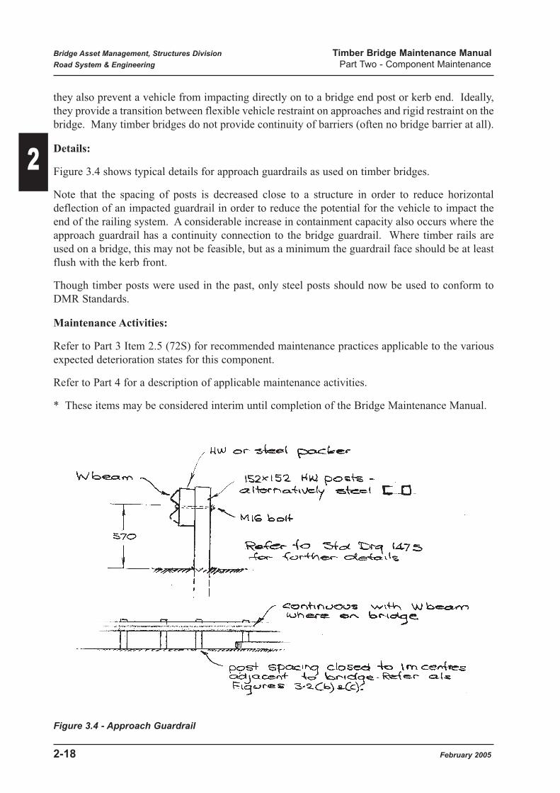
Details:
Figure 3.4 shows typical details for approach guardrails as used on timber bridges.
Note that the spacing of posts is decreased close to a structure in order to reduce horizontal
deflection of an impacted guardrail in order to reduce the potential for the vehicle to impact the
end of the railing system. A considerable increase in containment capacity also occurs where the
approach guardrail has a continuity connection to the bridge guardrail. Where timber rails are
used on a bridge, this may not be feasible, but as a minimum the guardrail face should be at least
flush with the kerb front.
Though timber posts were used in the past, only steel posts should now be used to conform to
DMR Standards.
Maintenance Activities:
Refer to Part 3 Item 2.5 (72S) for recommended maintenance practices applicable to the various
expected deterioration states for this component.
Refer to Part 4 for a description of applicable maintenance activities.
* These items may be considered interim until completion of the Bridge Maintenance Manual.
Figure 3.4 - Approach Guardrail
Bridge Asset Management, Structures Division Timber Bridge Maintenance Manual
Road System & Engineering Part Two - Component Maintenance
2-18 February 2005
2

4.0 Kerbs
4.1 Timber Kerbs (3T)
Refer to BIM Appendix D for a description of the four condition states applicable to this
component.
Purpose:
Timber kerbs serve a number of functions on timber bridges:
(1) The main purpose is to act as a containment device for vehicle wheels, generally in
conjunction with a timber or steel barrier. The kerb also provides an attachment point for
the associated posts.
(2) The kerb also kelps to more firmly tie down the outer ends of transverse deck planks where
the kerb is located above the outer girder.
Significance: Significance Rating 1
Particularly on bridges with timber rails, the kerb is probably providing greater containment
capacity than the railing system itself. However, timber kerbs are also generally very low,
particularly after overlays of wearing surface have been placed.
Originally, many timber bridges were constructed with concrete kerbs, which have in many cases
been replaced with timber kerbs as a result of on-going bridge maintenance.
Details:
The most common form of timber kerb consist of two hardwood members assembled to form a
200 x 200mm section. This helps ease component supply and also simplifies formation of
scuppers.
An alternative form of kerb fabricated from plywood is being successfully used and has the
advantage of straightness and long lengths.
Figure 4.1 shows typical details used for timber kerbs.
Maintenance Activity Numbers Units
3T1 Replace kerb in hardwood M
3T2 Replace kerb in ply M
Bridge Inspection Manual Component No. 3T
Bridge Asset Management, Structures Division Timber Bridge Maintenance Manual
Road System & Engineering Part Two - Component Maintenance
February 2005 2-19
2

Figure 4.1 - Timber Kerbs
Bridge Asset Management, Structures Division Timber Bridge Maintenance Manual
Road System & Engineering Part Two - Component Maintenance
2-20 February 2005
2

Materials:
Refer to Main Roads Specification MRS11.87 for acceptable timber species and properties for
both hardwood and plywood kerbs.
Maintenance Activities:
Refer to Part 3 Item 2.6 (3T) for recommended maintenance practices applicable to the various
expected deterioration states.
Refer to Part 4 for a description of applicable maintenance activities.
Further considerations are as follows:-
Routine Maintenance
Routine or preventative maintenance actions for timber kerbs will generally be identified and
carried out during Level 1 bridge inspections or follow-up RMPC actions. These activities would
be:
• Tightening or replacing kerb hold down bolts
• Application of surface preservatives or waterproofing agents.
The kerb attachment bolts should be checked for tightness as any looseness will reduce wheel
impact resistance, barrier post connection effectiveness, and possibly allow decking movements.
Where corrosion of bolts is evident, they should be withdrawn and replaced by galvanised bolts
of the same diameter if loss of section is evident. The bolt holes through the kerbs should be
coated / packed with CN emulsion or thick grease before bolt insertion.
Where areas of decay or cracking are noted, these areas should be coated with a chemical timber
preservative.
Where any active termite presence is detected during these operations, treatment shall be
programmed as soon as practical.
Programmed Maintenance:
Where a kerb member has deteriorated to Condition State 4, its adequacy to withstand impact or
to hold barrier posts will be compromised and it should be replaced. This will normally be
accomplished by a full length member in hardwood with suggested nominal gaps of 5 mm at the
pier butt joins (actual gap is not critical).
Unless a full bridge length of kerbing is being replaced, the cross section of the new member shall
correspond to that being replaced. To maintain the line of the kerb faces, a maximum deviation
of + 10mm measured by a string line on the inside face should be achieved.
Because plywood kerbs will generally be of non-standard size, they would normally only be used
for full bridge length replacement.
The junction region of the kerb and decking is an area of very high decay potential, requiring
particular attention. Timber decking should be dressed in the contact area to reduce high spots
and allow the kerb to be pulled down tight. All contact surfaces should be treated with a
Bridge Asset Management, Structures Division Timber Bridge Maintenance Manual
Road System & Engineering Part Two - Component Maintenance
February 2005 2-21
2

preservative and preservative grease applied. In order to remove any remaining air gaps, a
bituminous felt should also be laid over the contact area. (Where a kerb is formed from 2 layers
of hardwood timber, the internal contact area shall be similarly treated). The end grain of kerb
timbers shall be treated before assembly because of small end gaps. When ply kerbs are used, any
faces showing veneer glue lines shall be treated with sealant in order to prevent drying out and
opening up due to weather exposure. Painting of the kerb may satisfy this requirement.
Existing kerb attachment bolts may be used for the new kerb, unless corrosion of the bolts has
occurred in which case galvanised M20 replacement bolts shall be used. Where bolts can't be
extracted or a new girder is also installed, attachment bolt sizes and spacings as shown in Figure
17.1(b) should be used. As well, where bolt head washers bear directly on a ply kerb surface,
larger washer sizes shall be used as shown in Figure 17.1(b).
All bolt holes through kerbs should be treated with a preservative and a grease or petroleum jelly
applied to the bolt shank before insertion in order to improve water tightness.
On bridges up to 8 metres width, the kerbs should be painted white in order to provide enhanced
protection to the timber and also extra delineation for traffic. For wider bridges, painting may still
be considered in order to improve member durability.
Consideration may be given to providing light metal spouts at scuppers to shed water away from
decking ends as shown in Figure 4.1.
4.2 Concrete Kerbs (3C)
Refer to BIM Appendix D for a description of the four condition states applicable to this
component.
Purpose:
Concrete kerbs serve a number of functions on timber bridges:
(1) The main purpose is to act as a containment device for vehicle wheels, generally in
conjunction with a timber or steel barrier. The kerb also provides an attachment point for
associated posts.
(2) The kerb also helps to more firmly tie down the outer ends of transverse deck planks were
the kerb is located above the outer girder.
Significance: Significance Rating 1
Particularly on timber rail bridges, the kerb is probably providing greater containment capacity
than the railing system itself. However, concrete kerbs are also generally very low, particularly
after overlays of wearing surface been placed.
Maintenance Activity Numbers Units
3C1 Replace kerb in concrete M
Bridge Inspection Manual Component No. 3C
Bridge Asset Management, Structures Division Timber Bridge Maintenance Manual
Road System & Engineering Part Two - Component Maintenance
2-22 February 2005
2

Details:
The kerbs were cast in-situ on the timber bridge decking, with details as shown in Figure 4.2.
Maintenance Activities:
Refer to Part 3 Item 2.7 (3C) for recommended maintenance practices applicable to the various
expected deterioration states for this component.
Refer to Part 4 for a description of applicable maintenance activities.
Figure 4.2 -Concrete Kerbs
Bridge Asset Management, Structures Division Timber Bridge Maintenance Manual
Road System & Engineering Part Two - Component Maintenance
February 2005 2-23
2

5.0 Deck
5.1 Timber Planks (29T)
Refer to BIM Appendix D for a description of the four condition states applicable to this
component.
Purpose:
The main function of timber decking is to transfer traffic loads to supporting girder members.
It also helps transfer transverse loads from wind and flood debris across the full width of the
bridge.
Significance: Significance Rating 3
Failure of individual deck planks will not generally lead to bridge unserviceability as wearing
surface or running planks may help wheel traversing of localised gaps. However , extensive areas
of deterioration could lead to heavy vehicle breakthrough.
Details:
Except for a small number of concrete decks, hardwood timber decking was the traditional form
of decking used. The decking was normally placed transversely (or skewed) across the bridge, as
shown in Figure 5.1(a). The thickness of deck planks also varied according to design class and
construction date.
Decking is spiked down at the outer girders only on to sacrificial spiking planks, with no
mechanical connection to the inner girders, in order to reduce spike induced cracking of the
girders.
A number of decks with longitudinally laid decking planks on top of transverse timber transoms
(cross beams) are also in service.
Maintenance Activity Numbers Units
29T1 Replace hardwood deck planks M2
29T2 Replace end spiking plank M
29T3 Replace and retighten running planks M
29T4 Replace longitudinal deck planks in timber M2
29T5 Splice hardwood deck planks Each
Bridge Inspection Manual Component No. 29T
Bridge Asset Management, Structures Division Timber Bridge Maintenance Manual
Road System & Engineering Part Two - Component Maintenance
2-24 February 2005
2

Figure 5.1(a) - Hardwood Decking
Bridge Asset Management, Structures Division Timber Bridge Maintenance Manual
Road System & Engineering Part Two - Component Maintenance
February 2005 2-25
2

Failure Mechanism:
The major defect found in timber decking is rotting which generally begins in the contact area
below the kerb because of moisture entrapment and also because of exposure of the plank ends to
the weather. The normal failure mechanism is for hole to open in the deck allowing wheel loads
to penetrate. Deteriorated planks with section loss due to rotting, termite or fire damage may also
fail in bending under the action of wheel loads.
Materials:
Refer to Main Roads Specification MRS11.87 for acceptable timber species and properties for
hardwood decking. Where full re-builds of decks are to be undertaken, supply of materials in one
species only is preferred in order to maintain similar deflection and load carrying characteristics
from plank to plank.
Maintenance Activities:
Refer to Part 3 Item 2.8 (29T) for recommended maintenance practices applicable to the various
expected deterioration states.
Refer to Part 4 for a description of applicable maintenance activities.
Further Considerations are as follows:-
Routine Maintenance:
Routine or preventative Maintenance actions for timber deck planks will generally be limited to
the application of preservative materials to the exposed ends of the planks. This would normally
be accomplished using a preservative and a thick grease on the end grain of the planks. This
should be renewed at least every 3 years or as required and would be carried out as an RMPC
procedure.
During Level 1 inspections, where any active termite presence is detected, treatment shall be
programmed as soon as practical.
Any looseness noted in decking would normally be the result of loss of girder camber or possibly
crushing of spiking planks, requiring follow-up work on the relevant components.
Programmed Maintenance:
Where hardwood deck planks have deteriorated to Condition State 4, they must be replaced
because of the very high potential for failure under traffic loads. Where individual planks or part
areas of the deck require replacement, this will normally be accomplished by substitution of new
hardwood planks, the main requirements being adequacy of both strength and tightness.
Plank strength will be determined not only by MRS 11.87 requirements (stress grade and
durability), but also by plank thickness which was determined by bridge Design Class. Figure
5.1(a) shows the required thicknesses for 'A' and 'B' Class decks, while details for other classes
will be shown on the original drawings.
Bridge Asset Management, Structures Division Timber Bridge Maintenance Manual
Road System & Engineering Part Two - Component Maintenance
2-26 February 2005
2

In practice, existing plank thickness may vary from plan requirements, and the new decking
should correspond in depth to adjacent members. Where new decking is supplied thicker than
adjoining planks, the new timber should be sized to the same vertical dimension. In no case shall
the spiking plank or girder be trimmed back to accommodate the overthick deck plank.
Unless shown otherwise on the drawings, deck planks should be replaced as single full length
members, as continuity will then provide maximum strength. However, for short term repair
situations, on in cases where insufficient decking length is available, splicing of short sections of
decking may be used. Suitable details for making splice connections are shown in Figure
5.1(c)(1). Alternative splicing methods should be submitted to Structures Division for approval.
Any length of decking must span over a minium of two girders.
Localised temporary repairs to deteriorated decking may be made prior to plank replacement by
the method shown in Figure 5.1(c) (2).
The standard method for decker assembly on the girders requires each plank to be double spiked
down on to the spiking planks on top of the outer girders. The planks are not to be spiked to
internal girders. The spikes are to be staggered as shown in Figure 5.1(b) to reduce the potential
for splitting in the spiking plank.
Spikes are to be 16mm diameter round and will typically be 230mm long for 125mm timbers, but
the length requires adjusting for thinner timbers to prevent spike penetration of the actual girder
top.
Old specification requirements of using cup head, pan head or ewbank heads, but not countersunk
spike heads, should be adhered to. However, it is not practical to retain old requirements of not
driving heads into the decker surface because of the requirement to seat timber kerbs. (This
requirement was compatible with the old cast in-situ kerbs).
Deck rebuilds or replacement of areas of decking will require removal of kerbs (or kerb segments)
in order to allow existing spike removal and re-spiking. Old decking will often require to be cut
and split and spikes oxy cut off due to the difficulty in extracting old spikes.
Where individual planks are to be replaced, this is commonly achieved by cutting out the plank
and spikes, and inserting the replacement plank under the kerb (possibly with some kerb
loosening). If tightness cannot be achieved, bolted straps may be attached.
Bridge Asset Management, Structures Division Timber Bridge Maintenance Manual
Road System & Engineering Part Two - Component Maintenance
February 2005 2-27
2

Figure 5.1(b) - HW Decking Details
In order to keep decking tight and so reduce movement wear and rattling under load, it is
cambered or sprung down over the girders. Decking should be laid with the heart side downwards
as this results in the outer ends bending upwards, with the action of spiking at the ends producing
greater contact at inner girder supports. If a plank is warped towards the heart sufficiently to
prevent full and tight bearing on all girders when spiked at the ends it shall be rejected or re-
seasoned to eliminate warp. Saw cuts shall not be used to achieve this.
Decking timber shall be stacked on site to the requirements of MRS 11.87. The top layer of
decking should be turned at frequent intervals so that it does not warp in one direction only.
The length of new planks should correspond to that adjacent members, but in no case should the
decking protrude less than 50mm past the outside edge of the kerb.
Bridge Asset Management, Structures Division Timber Bridge Maintenance Manual
Road System & Engineering Part Two - Component Maintenance
2-28 February 2005
2

The outer ends of hardwood deck planks at the kerb support area shall be dressed to allow the kerb
to be pulled down tightly. Because of the potential for decay in the exposed outer ends and contact
surfaces, a timber preservative should be applied in these regions of new planks.
The end grain of the plank and contact areas with the spiking plank, kerb and girders shall have a
thick preservative grease applied. In order to further reduce any air gaps at the contact surfaces,
a bituminous felt shall also be placed. Refer to Part 1 Section 7.5.2 for comments.
Where new planks are to be placed the basic procedures would be:-
• Remove wearing surface (& running planks) over defective area.
• Release bolts and lift kerbs (where required).
• Cut out defective planks and remove spikes (cut off where required).
• Place new planks and respike with 2 spikes at each end.
• Replace & rebolt kerbs
• Reinstate wearing surface
• Recamber girders if decking is loose.
It should be remembered that when partial deck replacement is programmed, that the numbers of
planks required often increases once a deck is opened up. Rotting under wearing surfaces or
running planks is difficult to determine before removal of these components.
Where full span deck replacement is required, use of alternative materials such as plywood, steel
decking or PSC decking may also be considered.
Where decking has deteriorated to Condition State 3, due to rotting, maintenance activities will
generally consist of monitoring and the application of preservatives to the defect areas. Where
there is extensive areas of deck rot such as adjacent to kerbs, some use has been made of screwed
down thin galvanised steel sheeting to help spread wheel loads. Section 17.4 discussed the
application and effectiveness of this process.
The use of a concrete overlay on defective timber decking is not recommended.
Bridge Asset Management, Structures Division Timber Bridge Maintenance Manual
Road System & Engineering Part Two - Component Maintenance
February 2005 2-29
2

Figure 5.1(c) - Deck Repairs
Bridge Asset Management, Structures Division Timber Bridge Maintenance Manual
Road System & Engineering Part Two - Component Maintenance
2-30 February 2005
2

5.2 Plywood Sheets (20T)
Refer to BIM Appendix D for a description of the four condition states applicable to this
component.
Purpose:
The main function of plywood decking is to transfer traffic loads to supporting girder members.
It also helps transfer transverse loads from wind and flood debris across the full width of the
bridge.
Significance: Significance Rating 3
Because ply sheets are 1.2m width, partial deck plate action occurs, improving distribution of
traffic loads.
Details:
Plywood decking or "Bridgewood" was developed commercially in Queensland as an alternative
decking material for timber bridges and is installed as a maintenance replacement for original
hardwood decks. The 1.2m wide sheets are generally placed transversely with a variety of hold
down mechanisms. Figure 5.2(a) shows typical details for these decks. An alternative form of
hold downs for ply decks as shown in Figure 5.2(c) may also be considered. The use of strap
belting obviates the need for the normal extensive drilling of girders, thereby helping to improve
girder durability. However, the number of holes to be drilled through the ply deck will double. It
is essential for this bolting system to remain tight to stop movement of the ply sheets on the
girders. Ply sheets have been used conventionally with kerbs, or without kerbs and with barrier
posts bolted directly to the ply. Limited cantilevering of the ply past the outer girder is possible,
the extent depending on ply thickness.
Ply sheets for bridge decks are formed from nominal 25 to 30mm thick conventionally made ply
sheets which are cold bonded together (with self tapping screws applying the required pressure
for glue setting).
For road decking, the ply is supplied in nominal 130 or 155 mm thicknesses, while for footways
it may typically be 25 to 50mm thick.
Maintenance Activity Numbers Units
20T1 Replace ply sheet Each
20T2 Replace deck planks in ply Each
20T3 Replace longitudinal deck planks in ply Each
Bridge Inspection Manual Component No. 20T
Bridge Asset Management, Structures Division Timber Bridge Maintenance Manual
Road System & Engineering Part Two - Component Maintenance
February 2005 2-31
2

Figure 5.2(a) - Plywood Decking
Bridge Asset Management, Structures Division Timber Bridge Maintenance Manual
Road System & Engineering Part Two - Component Maintenance
2-32 February 2005
2
Failure Mechanism:
Rotting of the pine veneers making up the ply sheets due to failure of the CCA treatment envelope
would lead to failure under load from bending, shear or punching action.
Materials:
The supply of plywood components for roadway and footpath decking is covered in MRS 11.87
- Supply of Timber Bridge Materials and Components. It is important that the requirements for
stacking at site are also adhered to.
Maintenance Activities
Refer to Part 3 Item 2.9 (20T) for recommended practices applicable to the various expected
deterioration states for this component.
Refer to Part 4 for a description of applicable maintenance activities.
Further considerations are as follows:
Routine Maintenance:
Routine or preventative maintenance will consist of:
(1)Maintaining holding down bolt tightness. If bolts are loose, movement of ply sheets may lead
to wear of the ply at support surfaces and will contribute to the cracking of the wearing surface at
transverse sheet joints.
Both holding down and distributor bolts hall be checked and tightened where required.
(2)Maintaining an effective sealant on the exposed ends of the ply sheets. Because the sheet ends
are generally exposed to the sun and weather, delamination of the ply layers will occur unless a
protective sealant is present. Refer to Figure 17.7(b) for recommended products.
Programmed Maintenance:
Maintenance work with plywood decking will generally be associated with full bridge re-decking
as an alternative to using existing materials such as hardwood planks or steel trough. Generally
the opportunity is taken to widen the deck during this process because of the ability of the decking
to cantilever past the outside girders. The length of the cantilever is dependent on the ply
Warning:
Where existing bituminous wearing surface is to be removed from the top of ply decking,
extreme caution must be observed to prevent accidental damage to the top of the sheets.
Plywood is fabricated from F14 pine material and may be easily gouged by mechanical
equipment which is suitable for similar activities on hardwood decking.
Where site cutting of ply decking is required, care must be exercised to miss the internal self
tapping assembly screws (visible on one surface). Staples in the outer sheets (used during
scarfing processes) may also be present.
Bridge Asset Management, Structures Division Timber Bridge Maintenance Manual
Road System & Engineering Part Two - Component Maintenance
February 2005 2-33
2

thickness as shown in Figure 5.2(a). Where cantilevering is used, the outer girder and spiking
plank must be removed and a girder with the same diameter as the internal girders substituted
because traffic wheel loads can now track over the top of this girder.
Figure 5.2(b) shows current recommended details using a steel barrier and kerb which may be
considered in developing re-decking proposals.
It has been found necessary to bolt ply decking down on to each girder in order to reduce
movement and associated problems with the wearing surface. As a result, cambering is not
required for deck tightness, but a positive camber of 20 to 25mm should be built in to prevent
water collecting in sagged areas of decking.
Various hold-downs for the sheets have be used over the years, progressing from simple bolt and
washers to continuous channel as shown in Figure 5.2(a). Provided a substantial distributor
arrangement is used, however, the simple bolt and square washer is considered adequate and is
currently still being used. It should be noted that non-standard large size washers are to be used
for any bearing on ply surfaces.
The major defect associated with ply deck has been the cracking and break up of the AC wearing
surface over the butt joints between sheets, caused by differential deflections of adjacent sheets
under wheel passage. Even though both 130 and 155mm thick ply is structurally adequate for
normal girder spacings, it is recommended that the 155mm thick ply be used to help reduce these
deck deflections. As well, longitudinal steel channel distributors should be placed centrally
between each line of girders to help prevent differential edge deflections in the sheets. Figure
5.2(b) provides recommended details for distributors. A distributor is also placed near the barrier
post in order to control distortions in the ply sheets induced by post impacts.
Proposals for ply re-decking must be submitted to Structures Division for approval of details.
This also entails a structural check of the existing girders and substructure to determine their
adequacy (particularly where widening allows an extra lane of traffic on a bridge).
For a skewed bridge, the ply sheets will generally be supplied with the ends cut to the correct skew
in order to reduce the need for site cutting. Special care needs to be exercised when cutting ply
decking on site because of the embedded metal screws.
Ply sheets should be assembled to provide a uniform top surface to the deck and may need to be
packed up with CCA treated timber. Where traffic is allowed to use the deck prior to wearing
surface application, speed should be restricted to 20 km/hr because of the smooth surface of the
ply sheets.
Ply sheets are CCA treated, but additional preservative treatments should be carried out. Anti-
fungal preservative, grease and layer of bituminous felt should be placed at all contact surfaces
with girders, spiking planks or kerbs. Overall waterproofing of the deck will be enhanced by the
placement of a polyurethane elastomer joint filler at the transverse butt joints between sheets as
shown in Figure 5.2(b). A timber drip strip should also be tacked to the outer edge of the sheet
soffit to prevent water return under the sheet.
Bridge Asset Management, Structures Division Timber Bridge Maintenance Manual
Road System & Engineering Part Two - Component Maintenance
2-34 February 2005
2

Figure 5.2(b) - Plywood Details 1
Bridge Asset Management, Structures Division Timber Bridge Maintenance Manual
Road System & Engineering Part Two - Component Maintenance
February 2005 2-35
2

Figure 5.2(c) - Plywood Details 2
Bridge Asset Management, Structures Division Timber Bridge Maintenance Manual
Road System & Engineering Part Two - Component Maintenance
2-36 February 2005
2

Figure 5.2(d) - Special Washer
Bridge Asset Management, Structures Division Timber Bridge Maintenance Manual
Road System & Engineering Part Two - Component Maintenance
February 2005 2-37
2

Before the application of a bituminous wearing surface, a primer should be applied to the ply top
surface which must be dry and free from dust or salts. Where the ambient temperature is above
10°C, the bituminous primer shall be a cationic rapid set chemical emulsion.
Below 10°C, a rubberised emulsion (10% latex) could be used to maintain good adhesion. Prior
to priming, the joints between sheets shall be filled with joint sealant, and other sealant such as
self adhesive fabric joint tape added where detailed. The decking surface is then sprayed with the
appropriate emulsion, including the exposed sheet ends for weather protection. Where detailed
on the drawings, apply geofabric (non-self adhesive) to the entire deck or panel joints. A further
coating of emulsion is then applied to the geofabric surface. The final wearing surface is then to
be applied.
The basic procedure for redecking in plywood would be:-
• Remove existing DWS, kerbs and deck. Where carried out under traffic, progressive
removal of old decking and replacement with ply sheets may be considered.
• Where deck cantilevering is detailed, the outer girders and spiking planks are to be replaced
by girders of the same diameter as the inner girders.
• Place ply sheeting, attach hold downs and, where detailed, attach distributors.
• Place kerb / barriers and wearing surface.
A superstructure replacement option using ply decking on steel girders has recently been
developed, utilizing a 20mm chip seal surfacing as opposed to the conventional AC surfacing used
so far in Queensland. Similar details should also be applicable to ply redecking on timber girders.
Because of the shallow thickness surfacing, a special top washer for girder and distributor bolt
heads has also been developed. Details of this "jellyfish" washer are shown a Figure 5.2(c). This
washer is still a concept and not yet available commercially "off the shelf", but could be produced
if there were sufficient maintenance needs.
Where an existing ply sheet itself has deteriorated to Condition State 4, it must be replaced to
restore deck capacity. The thickness of the replacement sheet should correspond to that of
adjacent sheets in order to give compatible deflection characteristics. All details and processes
will generally be as previously described for new decks.
Where sheet condition is satisfactory, but the DWS has deteriorated to Condition State 4 at
transverse joints, producing excessive roughness, the full wearing surface should be replaced. As
stated previously, care is needed during DWS removal from plywood as one bridge was seriously
damaged during this process. Reduction in potential for further break up at the joints requires
both:-
(1) Prevention of sheet movements / rotations on the girders.
(2) Prevention of differential sheet edge deflections between the girders.
In general, existing hold downs (as shown in Figure 5.2(a)) may be retained but additional items
may be needed to ensure connection to each girder.
Simple bolt and square top washer arrangements are considered satisfactory provided substantial
distributors are in place. The longitudinal channel type presumably supplies maximum restraint
against movement.
Bridge Asset Management, Structures Division Timber Bridge Maintenance Manual
Road System & Engineering Part Two - Component Maintenance
2-38 February 2005
2

Differential edge movement can only be reduced by using longitudinal distributors as shown in
Figure 5.2(b) and these should be installed if not in place.
Assembly of the distributor system under traffic by using coach screws can also be considered.
Waterproofing of the deck should also be carried out if such treatment is not in place.
(1) If gaps between sheets are 5mm or greater, place a foam backing strip and seal joint with
a Megaprene 40 (or equivalent) filler.
(2) Where gaps are small, apply either a self adhesive fabric joint tape (Bitac or equivalent)
or tack down light metal strips (Figure 7.7(c) Part1).
Refer to Appendix B for typical bridge drawings illustrating ply deck details.
5.3 Concrete Slab
Refer to BIM Appendix D for a description of the four condition states application to this
component.
Purpose:
The main function of the concrete deck slab is to transfer traffic loads to supporting girder
members.
The slab also helps to transfer transverse loads from wind and flood debris across the full width
of the bridge.
Significance: Significance Rating 3
Because of ample thicknesses adopted in the past it is unlikely that a concrete deck slab will fail
catastrophically. However, with severe loss of reinforcing area and spalling, it is possible for
wheels to punch through a slab, causing traffic dislocation.
Details:
Concrete slab decks were incorporated on a number of bridges as an alternative to the normal
timber deck. Figure 5.3(a) shows typical details for the most common type. Figure 5.3(b) shows
another more complex type which incorporated steel shear connector plates embedded into both
the timber girders and the concrete slab.
Failure Mechanism:
Where reinforcing has corroded away, the deck slab is expected to fail under punching shear
action, with the essentially unreinforced concrete breaking through as a block.
Maintenance Activity Numbers Unit
Refer to general concrete repair Activities
Bridge Inspection Manual Component No. 20C
Bridge Asset Management, Structures Division Timber Bridge Maintenance Manual
Road System & Engineering Part Two - Component Maintenance
February 2005 2-39
2

Spalling of the kerb at barrier post anchor bolt locations will also lead to reduced barrier
containment capacity.
Maintenance Activities:
Refer to Part 3 Item 2.10 (20C) for recommended maintenance practices applicable to the various
expected deterioration states for this component.
Refer to Part 4 for a description of applicable maintenance activities.
Bridge Asset Management, Structures Division Timber Bridge Maintenance Manual
Road System & Engineering Part Two - Component Maintenance
2-40 February 2005
2

Figure 5.3(a) - Concrete Slab Deck - Type 1
Bridge Asset Management, Structures Division Timber Bridge Maintenance Manual
Road System & Engineering Part Two - Component Maintenance
February 2005 2-41
2

Figure 5.3(b) - Concrete Slab Deck - Type 2
Bridge Asset Management, Structures Division Timber Bridge Maintenance Manual
Road System & Engineering Part Two - Component Maintenance
2-42 February 2005
2

5.4 Prestressed Concrete Planks (29P)
Refer to BIM Appendix D for a description of the four condition states applicable to this
component.
Purpose:
The main function of PSC plank decking is to transfer traffic loads to supporting girder members.
It also helps transfer transverse loads from wind and flood debris across the full width of the
bridge.
Significance: Significance Rating 3
Because PSC deck planks are 600 mm wide and carry no wearing surface, a failure would allow
wheels to drop, with possible bridge closure depending on the extent of the deck collapse.
Longitudinal steel distributors used in conjunction with these planks will partly reduce the
potential for this eventuality due to the development of some longitudinal distribution of loads.
Details:
PSC planks are a proprietary product and have been installed as a maintenance replacement for
the original hardwood decks. Figure 5.4 shows details applicable to this type of decking.
The precast units are bolted down to the girders with an open gap of approximately 12 mm
between planks.
Failure Mechanism:
Because prestressing strands are under a high tensile stress, they are susceptible to the effects of
corrosion. Excessive corrosion will lead to strands fracturing with loss of both bending and shear
capacity in the units due to insufficient prestressing force. Because the slabs are quite rigid, they
are prone to torsion (twisting) failure if the individual seatings on the timber girders are not
coplanar.
Materials:
Refer to Specification MRS 11.87 for supply and site storage requirements for prestressed
concrete decking planks.
Maintenance Activity Numbers Unit
29P1 Replace PSC plank Each
29P2 Reseat PSC plank Each
29P3 Replace deck planks in PSC Each
Bridge Inspection Manual Component No. 29P
Bridge Asset Management, Structures Division Timber Bridge Maintenance Manual
Road System & Engineering Part Two - Component Maintenance
February 2005 2-43
2

Figure 5.4 - PSC Plank Decking
Bridge Asset Management, Structures Division Timber Bridge Maintenance Manual
Road System & Engineering Part Two - Component Maintenance
2-44 February 2005
2

Maintenance Activities
Refer to Part 3 Item 2.11 (29P) for recommended maintenance practices applicable to the various
expected deterioration states for this component.
Refer to Part 4 for a description of applicable maintenance activities.
Further considerations are as follows:-
Routine Maintenance:
Routine or preventative maintenance will consist of maintaining bolt tightness for plank hold
downs and distributors.
If hold down bolts are loose, plank movement may lead to wear of the timber support surfaces.
However, the major concern is that any twisting occurring in the rigid planks can lead to a torsion
failure of the plank. If distributors are loose, wheel loads taken on individual planks will increase
due to reduction in load transfer provided by the distributors.
Any stones or debris lodged in transverse gaps may lead to edge spalling due to movements or
wheel loading and should be removed where practical.
Programmed Maintenance:
Maintenance work using PSC Planks will generally be associated with full deck replacement as
an alternative to using existing materials. PSC planks are a commercial proprietary product and
details need to be initially sought from the manufacturer. The new decking proposal shall then be
submitted to Structures Division for approval of details. Because of the increased mass and width
of the deck, a structural check of the existing substructure and proposed girder arrangement will
also need to be carried out to determine adequacy of piles, headstocks and girders.
PSC plank decking has been used successfully for square bridges. However, it may be possible
to use it on small skew bridges, provided it is also placed on the skew. The feasibility of such a
geometry would need to be determined by consultation with the manufacturer.
Because of PSC planks are detailed to cantilever past the outer girder line, some widening of a
deck will normally occur, as shown in Figure 5.4. The manufacturer's drawings allow adjustment
of girder spacing to 1.5m maximum, but there is no limit set for cantilever length. It is
recommended that the distance between the inner face of the kerb and the centre line of the outer
girder be limited to 600mm provided slab design and structure checks are satisfactory. Because
of the cantilevering, the outer girder and spiking plank should be replaced by a girder of the same
diameter as the inner girders.
There are two deck layout possibilities:-
(1) Using existing girder centres with holding down bolt holes located accordingly.
(2) Using modified girder spacing layouts as provided by the manufacturer to suit some
standard deck / girder layout.
The most important consideration in placing of PSC plank decking is the provision of a planar
surface to the top of the girders. Any lack of support at the girders may allow twisting of the deck
Bridge Asset Management, Structures Division Timber Bridge Maintenance Manual
Road System & Engineering Part Two - Component Maintenance
February 2005 2-45
2

planks to occur under wheel loads, giving a high potential for torsion failure. Limited trimming
of girder tops may be made before using shims to take our remaining irregularities (preference is
for no cuts, however). Localised notching of girder tops to accept individual planks must not be
used.
Cambering of girders is not required, because the decking is bolted to each girder.
Because of open deck joints, protection must be applied to girder tops to reduce exposure to water.
This may take the form of continuous metal flashing along the girder tops, after application of
timber preservative and grease to the contact surface. Alternatively, a grease impregnated tape
(densotape or equivalent) may be used. Refer to typical details shown in Figure 7.5(c). Part 1 the
recesses in the top of the concrete deck planks for girder bolt heads should also be sealed after
bolt placing in order to reduce water penetration into the drilled girder holes.
Where delineator posts only are required, fasteners may be incorporated in the outer faces of the
kerbs for post attachment. Where, however, continuous barrier is required because of bridge
height etc, significantly larger post loads are possible. The manufacturer should be informed of
this requirement, to determine if modification of the standard slab design is required to safely
transfer such barrier loads.
The basic procedure for redecking using PSC planks would be:-
• Remove existing DWS, kerbs and deck.
• Replace outer girders with full size and modify internal girder locations if detailed.
• Trim girder tops to provide suitable seating and provide top protection.
• Place PSC decking, drill and attach holding down bolts.
• Install metal distributors, and barriers where so detailed.
Where an individual PSC plank has deteriorated to Condition State 4 it must be replaced by a new
member. The reason for the defect must be determined, in case modifications to the supports are
required to prevent a repetition of the deterioration. The new PSC plank shall have the same
cross-section dimension as that being replaced. Details of the proposed replacement members
shall be submitted to Structures Division for approval.
The timber contact surfaces at the girders shall be treated with a chemical preservative, a grease
and a bituminous felt. After assembly the girder bolt recesses shall be sealed. Distributor bolts
must also be re-assembled.
5.5 Steel Trough Decking (30S)
Refer to BIM Appendix D for a description of the four condition states applicable to this
component.
Bridge Inspection Manual Component No. 30S
Bridge Asset Management, Structures Division Timber Bridge Maintenance Manual
Road System & Engineering Part Two - Component Maintenance
2-46 February 2005
2

Purpose:
The main function of steel trough decking is to transfer traffic loads to supporting girder members.
It also helps to transfer transverse loads from wind and flood debris across the full width of the
bridge.
Significance: Significance Rating 3
Because steel troughing sheets are stitched together with screws, fracture of any one trough
section will not necessarily lead to bridge closure, but possible consequent sagging may lead to
surface depressions. Where deterioration is over a larger area, traffic wheels may break through
the decking in the event of failure.
Details:
Steel trough decks have been in service since the 1970's as a replacement for the original
hardwood timber decking. Originally, the troughs were filled and overlaid by a bituminous fill,
material such as AC, but this has, in general, proven to be unsuccessful. Because the DWS is
porous, water is collected at the interface between the fill and the steel troughing. This, combined
with mechanical abrasion due to differential movement between the trough upstands and the fill,
eventually causes full loss of the galvanizing layer on the tops and sides of the troughing. This
then results in severe corrosion and loss of steel section area. Surprisingly however, the
galvanising is sometimes found intact on the top of the lower surface.
Where, however, a reinforced concrete fill has been placed in the troughs, the system has worked
successfully with little or no reported deterioration.
Deck cantilevers past the outer girder support should be limited to 500mm, as experience has
shown difficulty in retaining fill material, particularly with bituminous material, due to
movements under the action of wheel loads.
Longitudinal troughing, placed on transverse steel transoms (crossbeams) has been used and has
performed satisfactorily.
Figure 5.5(a) shows general details for steel trough decks.
Failure Mechanism:
One common defect found in steel troughs is transverse cracking indicating complete structural
failure - refer to Figure 5.5(c) for the general appearance. This cracking may be between girders
Maintenance Activity Numbers Units
30S1 Remove and replace steel trough decking M2
30S2 Strengthen steel trough decking Lump sum
30S3 Replace deck planks in steel M2
30S4 Place reinforced concrete infill M3
30S5 Replace tap screws Lump sum
30S6 Place reinforced concrete slab M3
Bridge Asset Management, Structures Division Timber Bridge Maintenance Manual
Road System & Engineering Part Two - Component Maintenance
February 2005 2-47
2
or over the top and parallel to girders, in which case it is difficult to detect by observation from
below. Refer to Reference 11 for further information.
Corrosion of the upper surfaces of the troughing often causes excessive loss of section area, which
will lead to folding and buckling distortions or the punching through of vehicle wheels.
Perforation of the corroded trough sections also commonly occurs, with pin holes and associated
rust stains. The extent of severe deterioration may be gauged by impacting the area with a
geologist's pick.
Materials:
The supply and site storage requirements for steel trough decking are covered in MRS 11.87 -
Supply of Timber Bridge Materials and components.
Maintenance Activities:
Refer to Part 3 Item 2.12 (30S) for recommended maintenance practices applicable to the various
expected deterioration states.
Refer to Part 4 for a description of applicable maintenance activities.
Further considerations are as follows:-
Routine Maintenance:
Routine or preventative maintenance will consist of ensuring maintenance of holding down bolt
tightness. If decking is loose, movements under load can lead to failure of AC infill material.
Programmed Maintenance:
Maintenance work with steel trough decking will generally be associated with full bridge
redecking as an alternative to using existing material such as hardwood planking. Generally, the
opportunity is taken to widen the deck during this process because of the ability of the decking to
cantilever past the outside girders. Cantilevering is limited to 500 mm as shown in Figure 5.5(a).
Where cantilevering is used, the outer girder and spiking plank must be removed and a girder with
the same diameter as the internal girders substituted because traffic wheel loads can now track
over the top of this girder.
It has been found necessary to bolt steel decking down on each girder in order to reduce
movement and associated problems with infill and wearing surface. As a result, cambering is not
required for deck tightness, but a positive camber of 20-25mm should be built in to prevent water
collecting in sagged areas of decking.
Currently, the normal hold-down method for steel decking is continuous steel channel bolted
along the girder as shown in Figure 5.5(a). Previous use of coach screws as hold-downs does not
appear to have been successful.
Bridge Asset Management, Structures Division Timber Bridge Maintenance Manual
Road System & Engineering Part Two - Component Maintenance
2-48 February 2005
2

Figure 5.5(a) - Steel Trough Decking
Bridge Asset Management, Structures Division Timber Bridge Maintenance Manual
Road System & Engineering Part Two - Component Maintenance
February 2005 2-49
2

Any redecking proposal shall be submitted to Structures Division for approval. This process will
include a structural analysis of the existing girders and substructure because of the increased deck
mass.
As well, loads will increase if an additional lane of traffic has access as a result of widening.
It is recommended that a reinforced concrete infill rather than AC be used with steel decks because
of proven superior performance. Typical details are shown in Figure 5.5(b).
It is recommended that a neoprene strip be laid along girder tops prior to decking placement to
reduce wear at the contact surfaces. The top surfaces of the girders and spiking plank should also
be treated with an anti-fungal preservative, grease and a bituminous felt material placed.
The basic procedures for redecking in steel would be:-
• Remove existing DWS, kerbs and deck. Where carried out under traffic, progressive
removal of old decking and replacement of steel trough sheets may be used. Individual
sheets should be screwed together prior to allowing traffic access.
• Where deck cantilevering is detailed, the outer girders and spiking planks are to be replaced
by girders of the same diameter as the inner girders.
• Place steel decking, install screws, and hold downs.
• Place kerb and infill / wearing surface. Where concrete infill is used, provision shall be
made to allow extraction of girder and hold down attachment bolts.
Where a part or all of the existing steel troughing has deteriorated to Condition State 4, it must be
replaced to restore deck capacity. Details and processes will generally be as described above. If
the existing troughing is found to cantilever more than 500mm past the outer girder (to inside face
of kerb), advise Structures Division to determine if cantilever lengths require to be modified.
In some cases, where cracking failure of the troughing has occurred as shown in Figure 5.5(c), an
alternative repair method sometimes used is to place strengthening plates bent to the profile of the
existing troughing. For cracking between girders, these may be welded from the bottom, while
for cracking over a girder, removal of DWS will be required to give access to the top surface.
Care should be exercised when welding on the thin 3mm troughing plate and any galvanised
surface damaged by welding shall be protected by a cold galvanising product.
In cases where troughing is in a very poor condition, it may be used as permanent formwork for
the placement of a structurally reinforced concrete slab, as an alternative to replacement. Figure
5.5(c) shows details for a typical job. As opposed to all cases above, the troughing is assumed to
have no residual capacity. If this option is required, submit details to Structures Division for
preparation of suitable details. It is essential that provision is made to allow extraction of the
channel / girder hold down bolts after concrete deck placement in order to simplify any possible
removal and replacement of defective timber girders.
Reference
11. Infratech Systems and Services. (1998). Performance of Steel Trough Decks on Timber
Girder Bridges.
Bridge Asset Management, Structures Division Timber Bridge Maintenance Manual
Road System & Engineering Part Two - Component Maintenance
2-50 February 2005
2

Figure 5.5(b) - Steel Decking
Bridge Asset Management, Structures Division Timber Bridge Maintenance Manual
Road System & Engineering Part Two - Component Maintenance
February 2005 2-51
2

Figure 5.5(c) - Concrete Slab
Bridge Asset Management, Structures Division Timber Bridge Maintenance Manual
Road System & Engineering Part Two - Component Maintenance
2-52 February 2005
2

5.6 Timber Crossbeams
Refer to BIM Appendix D for a description of the four condition states applicable to this
component.
Purpose:
The function of timber crossbeams is to support timber decking which is laid longitudinally.
Significance: Significance Rating 3
Timber crossbeams are important because the failure and collapse of a number in a group could
lead to failure of the longitudinal decking if it is required to span an excessive gap.
Details:
Decks composed of longitudinal timber planks supported on transverse timber cross beams (or
transoms) have been used on a number of bridges. Figure 5.6 shows typical details.
Failure Mechanism:
These members will generally fail in bending due to loss of member capacity as a result or rotting
or cracking.
Maintenance Activities:
Refer to Part 3 Item 2.13 (28T) for recommended maintenance practices applicable to the various
expected deterioration states for this component.
Refer to Part 4 for a description of applicable maintenance activities.
Maintenance Activity Numbers Units
28T1 Replace crossbeam M
28T2 Place additional crossbeams M
Bridge Inspection Manual Component No. 28T
Bridge Asset Management, Structures Division Timber Bridge Maintenance Manual
Road System & Engineering Part Two - Component Maintenance
February 2005 2-53
2

Figure 5.6 - Timber Crossbeams
5.7 Steel Crossbeams (28S)
Refer to BIM Appendix D for a description of the four condition states applicable to this
component.
Purpose:
The function of steel crossbeams is to support steel trough or ply decking where this is laid
longitudinally.
Significance: Significance Rating 3
Steel cross beams are important because the failure and collapse of a number would lead to failure
in the trough decking because of its inability to now carry loads over a double span length.
Details:
Figure 5.7 shows common details and fastening methods for these members.
Maintenance Activity Numbers Units
28S1 Replace crossbeam M
Bridge Inspection Manual Component No. 28S
Bridge Asset Management, Structures Division Timber Bridge Maintenance Manual
Road System & Engineering Part Two - Component Maintenance
2-54 February 2005
2
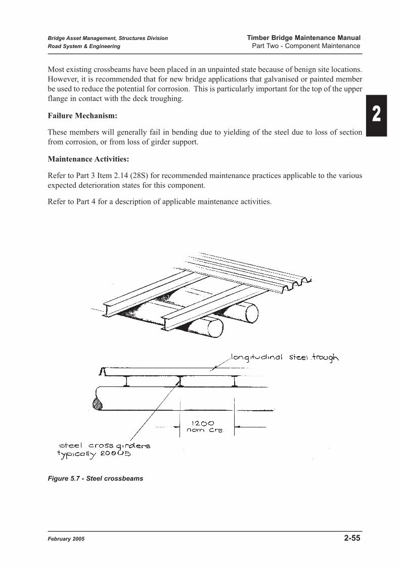
Most existing crossbeams have been placed in an unpainted state because of benign site locations.
However, it is recommended that for new bridge applications that galvanised or painted member
be used to reduce the potential for corrosion. This is particularly important for the top of the upper
flange in contact with the deck troughing.
Failure Mechanism:
These members will generally fail in bending due to yielding of the steel due to loss of section
from corrosion, or from loss of girder support.
Maintenance Activities:
Refer to Part 3 Item 2.14 (28S) for recommended maintenance practices applicable to the various
expected deterioration states for this component.
Refer to Part 4 for a description of applicable maintenance activities.
Figure 5.7 - Steel crossbeams
Bridge Asset Management, Structures Division Timber Bridge Maintenance Manual
Road System & Engineering Part Two - Component Maintenance
February 2005 2-55
2

5.8 Concrete Overlay (20C)
This system is not considered appropriate for future deck repairs and is included here for
completeness because two such treated bridges remain on our roads.
Refer to BIM Appendix D for a description of the four condition states applicable to this
component.
Purpose:
The main function of the concrete overlay was to try and extend the life of deteriorated timber
plank decks. The concrete was poured directly on top of the existing timber decking with very
little preparatory or repair work carried out on the timber members. The concrete layer also
formed the traffic surface, providing a smooth running surface which helps to reduce the increased
dynamic loads induced by traffic wheels as a result of deck roughness.
Significance: Significance Rating 2
The concrete overlay has been thought of as a wearing surface but it does have some structural
action. It is reinforced with a layer of steel mesh, enabling it to span across localized deck gaps
resulting from rotting in timber planks below. As well, there will be some minor improvement in
the distribution of wheel loads to individual deck planks and to the girder.
One benefit claimed for this system was that the overlay will effectively waterproof the members
below, reducing the rate of deterioration due to rotting. However, any significant cracking of the
concrete layer could negate this improvement.
The reduction in roughness induced wheel impact loads due to the smooth running surface is
probably the most significant benefit arising from this system.
Details:
Figure 5.8 shows typical details that have been used for concrete overlays. An increase in steel
quantity is suggested, however, as considerable cracking is sometimes observed in the slab, both
due to concrete shrinkage and the flexibility of the timber structure compared to the relatively
rigid overlay. There is also a weight penalty on the girders and substructure due to the extra mass
of the concrete overlay, compared to the normal AC wearing surface.
General:
The main defects noted with this system have been transverse shrinkage cracks, indicating
inadequate shrinkage reinforcement was traditionally used. However, severe crazed cracking with
loss of sections has occurred in a number of bridges, generally associated with a very flexible
superstructure or high vehicle impact areas (bottom of a sag alignment).
Maintenance Activity Numbers Units
20C1 Remove & replace cracked overlay M2
Bridge Inspection Manual Component No. 20C
Bridge Asset Management, Structures Division Timber Bridge Maintenance Manual
Road System & Engineering Part Two - Component Maintenance
2-56 February 2005
2

Figure 5.8 - Concrete Overlay
Bridge Asset Management, Structures Division Timber Bridge Maintenance Manual
Road System & Engineering Part Two - Component Maintenance
February 2005 2-57
2

The concrete surfacing was intended to be placed over deteriorated timber decking with little or
no timber repairs. The process used was to:
(a) pack excessive width gaps between planks
(b) place mesh reinforcement
(c) pour concrete decking
Because of the contact between the slab and the timber, the timber surface needed to be sprayed
with timber preservative to try and reduce the rate of timber degradation at the interface.
Use of the concrete overlay is not considered to be compatible with general strategies for
maintenance as given in 2.1.1 Part1 because of retention of deteriorated components. The
question of when the timber decking should be further considered is made more difficult because
the defective areas have been covered up. On-going rotting or termite attack may not become
apparent until the damage has reached the deck soffit.
Prior to any obvious failure of the overlay, visual inspection of the deck soffit, including
impacting with a crow bar, or drilling from below could be considered in order to estimate support
adequacy. Once a Condition State 4 failure of the overlay has occurred, however, it will be
necessary to determine if deterioration of the decking is the prime cause. Replacement of timber
planking may be then necessary. If the majority of the decking requires replacement, it is
recommended the full deck be replaced with timber planks with a bituminous wearing surface.
Programmed Maintenance Activities
Refer to Part 3 Item 2.15 (20C) for recommended maintenance practices applicable to the various
expected deterioration states for this component.
Refer to Part 4 for a description of applicable maintenance activities.
5.9 Stress-Laminated Timber (20T)
Refer to BIM Appendix D for a description of the four condition states applicable to this
component.
Maintenance Activity Numbers Units
20T4 Check stressing bars Each
20T5 Sleeve bolts Each
20T6 Restress SLT deck Lump sum
20T7 Replace stressing bar Each
20T8 Sleeve stressing bar Each
20T9 Replace anchor plates Each
20T10 Replace laminates Lump sum
Bridge Inspection Manual Component No. 20T
Bridge Asset Management, Structures Division Timber Bridge Maintenance Manual
Road System & Engineering Part Two - Component Maintenance
2-58 February 2005
2

Purpose:
Where a stress-laminated deck is placed as an alternative to a span of superstructure, its main
function is to transfer vertical and longitudinal traffic loads on a span to the substructure. It also
acts to transfer transverse loads such as wind and flood debris to the end supports. Alternatively,
a stress-laminated deck system may be supported by timber or steel girders where it is used as a
replacement for original decking.
Significance: Significance Rating 4
The full span deck is a primary structural member and any failure would lead to bridge
unserviceability and closure.
Details:
Only one stress-laminated timber bridge has so far been built in Queensland, consisting of timber
slab composed of vertical timber boards laid longitudinally, stressed transversely together at
intervals with conventional stressing bars to form a homogeneous slab - refer to Figures 5.9(a) &
(b) for details. This stress-laminated deck replaced the original timber deck, girders and corbels
and so spans from pier to pier.
A alternative forms of this construction are also shown in Figure 5.9(a). It should be noted that
any further construction using stress-laminated technology will almost certainly be using
plantation grown pine timber species, rather than hardwood because of its increasing supply
difficulty. Where pine timber is used, the form of construction would be a hollow box with stress-
laminated top and bottom flanges, in order to chive an adequate structural depth.
Failure Mechanism:
Stress-laminated decks function as a structural member due to shear transfer across the interface
between boards due to the imposed prestressing force from the transverse bars. If bar forces
reduce significantly due to timber shrinkage and creep or bar relaxation, the boards will begin to
slip vertically under wheel loads, causing excessive distortions. The resultant loss of load transfer
across the width of the deck could lead to overstressing and breaking of boards under heavy wheel
loads.
Maintenance Activities:
Refer to Part 3 Item 2.16 (20T - Stress Laminated) for recommended maintenance practices
applicable to the various expected deterioration states for this component.
Refer to Part 4 for a description of applicable maintenance activities.
Further considerations are as follows:-
Routine Maintenance
SLT decks generally require less maintenance than traditional timber construction and should not
exhibit loosening of components due to shrinkage etc.
Bridge Asset Management, Structures Division Timber Bridge Maintenance Manual
Road System & Engineering Part Two - Component Maintenance
February 2005 2-59
2

Figure 5.9(a) - Stress-laminated Timber Deck
Bridge Asset Management, Structures Division Timber Bridge Maintenance Manual
Road System & Engineering Part Two - Component Maintenance
2-60 February 2005
2

Figure 5.9(b) - Stress- Laminated Bridge
Bridge Asset Management, Structures Division Timber Bridge Maintenance Manual
Road System & Engineering Part Two - Component Maintenance
February 2005 2-61
2

Slippage of laminates
Distorted soffit prior to Jacking level
Figure 5.9(c) - S.L. Deck Failure
Bridge Asset Management, Structures Division Timber Bridge Maintenance Manual
Road System & Engineering Part Two - Component Maintenance
2-62 February 2005
2

The main objectives of preventative maintenance are to maintain protection against moisture
ingress through deck top and sides and to ensure a minimum level of prestress in the deck to
maintain structural actionof the deck slab. As each individual laminate board is envelope treated
with preservative, long term protection is expected.
• To prevent water access to the timber below, the integrity of the wearing surface and deck
water proofing system should be checked. Any cracks in the AC or depressions allowing
ponding should be repaired.
• The deck drainage should be clear and all scuppers unblocked (as regularly as possible).
• Prestress levels in the transverse stressing bars should be checked once per year. Reliance
on load cells has proven inadequate due to long term calibration requirements for the cells.
However, "lift off" tests using a hollow core prestressing jack may be used. This is
performed by pulling the end of a stressing bar and noting Jack load at the time the bar
anchor lifts off the main anchor plate. BAM will advise minimum bar forces required to
maintain a safe level of stress in the deck.
If bar forces are found to be below the minimum required, the SLT deck must be restressed.
Required stressing forces shall be as shown on the drawings and BAM will provide a
required specific stressing sequence. This is because any adjustment to a particular bar
force will affect the force in adjacent bars.
• Any minor corrosion of the exposed ends of stressing bars shall be cleaned and spot painted
to reduce the rate of deterioration.
Programmed Maintenance Activities:
If the wearing surface or waterproofing layer is found to be in a condition requiring replacement,
extreme care needs to be exercised in removing the material from softwood SLT decks.
If more than 1 or 2 laminates in a deck are found to have fractured, an engineering evaluation will
be needed to determine the cause and consequent repair method. Because of the difficulty of
replacing laminates (deck has to be supported and distressed), a fully designed replacement
procedure will be necessary.
If laminate slippage has occurred due to inadequate transverse stressing, an attempt should be
made to jack the deck soffit back to line before restressing, by jacking off falsework below the
deck.
Where a stressing bar is to be replaced due to corosion, the new bars shall be of the same form,
grade and diameter as the original bar and shall be painted using the product noted in Figure
17.10. The bar shall also be coated with grease before insertion in its duct.
Bridge Asset Management, Structures Division Timber Bridge Maintenance Manual
Road System & Engineering Part Two - Component Maintenance
February 2005 2-63
2

6.0 Footway
6.1 Timber Surface - HW Planks (4T)
Refer to BIM Appendix D for a description of the four condition states applicable to this
component.
Details:
Timber planks on footways are generally bare and of thinner dimension than roadway decking
(though roadway decking extension may sometimes be used). Figure 6.1 shows typical details.
General:
Generally comments applicable to roadway decking (Item 29T) will apply. Footways have the
added potential of danger to pedestrians due to surface roughness from gaps, non-planar top
surface or rot holes.
A Significance Rating of 1 for footway surface is appropriate.
Maintenance Activities:
Refer to Part 3 Item 2.17 (4T) for recommended maintenance practice applicable to the various
expected deterioration states for this component.
Refer to Part 4 for a description of applicable maintenance activities.
Maintenance Activity Numbers Units
4T1 Replace timber planks M2
4T2 Reposition / reseat timber planks M2
Bridge Inspection Manual Component No. 4T
Bridge Asset Management, Structures Division Timber Bridge Maintenance Manual
Road System & Engineering Part Two - Component Maintenance
2-64 February 2005
2
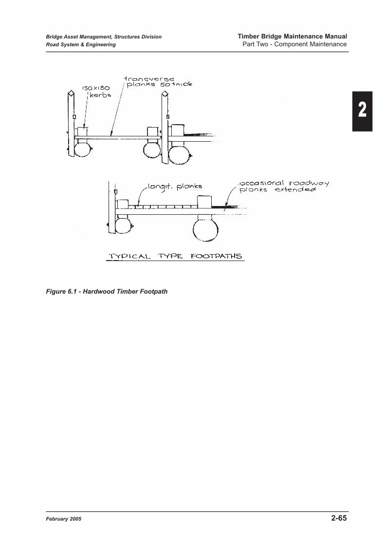
Figure 6.1 - Hardwood Timber Footpath
Bridge Asset Management, Structures Division Timber Bridge Maintenance Manual
Road System & Engineering Part Two - Component Maintenance
February 2005 2-65
2

6.2 Timber Surface - Ply Sheets (4T)
Refer to BIM Appendix D for a description of the four condition state applicable to this
component.
Details:
Plywood sheets on footpaths are covered by a non-slip painted surfacing and are generally of
thinner dimension than regular decking (though roadway decking extensions have been used).
Figure 6.2 shows typical details.
General:
Generally comments applicable to roadway decking (Item 20T) apply. Footways have the added
potential of danger to pedestrians due to surface roughness from gaps or steps in level at sheet
junctions. As well, loss of anti-slip surfacing may lead to pedestrian safety concerns.
A Significance Rating of 1 for the footway surface is appropriate.
Maintenance Activities:
Refer to Part 3 Item 2.18 (4T-Ply) for recommended maintenance practices applicable to the
various expected deterioration states for this component.
Refer to Part 4 for description of applicable maintenance activities.
Additional:
Plywood sheets up to 34 mm thickness shall be attached with self drilling type fasteners.
Self drilling fasteners used to connect to a steel girder shall be 14 gauge hexagonal head self
drilling screws with a minimum of 20 threads per inch, or 14 gauge hexagonal head screws (self
tapping or non-self tapping) with 10 threads per inch utilising a 5.8 mm diameter pilot hole, and
manufactured in accordance with AS3566 and shall have a minimum of 40 micron hot dipped
galvanising or 50 micron mechanical / chemical galvanised corrosion protection over the length
of the screw. The Contractor shall produce a manufacturer's test certificate if requested by the
Superintendent.
Maintenance Activity Numbers Units
4T3 Replace ply sheet Each
4T4 Reseat ply sheet Each
Bridge Inspection Manual Component No. 4T
Bridge Asset Management, Structures Division Timber Bridge Maintenance Manual
Road System & Engineering Part Two - Component Maintenance
2-66 February 2005
2

Figure 6.2 - Plywood Footpath
Bridge Asset Management, Structures Division Timber Bridge Maintenance Manual
Road System & Engineering Part Two - Component Maintenance
February 2005 2-67
2

6.3 Asphalt Surface - Steel Trough (4O)
Refer to BIM Appendix D for a description of the four condition states applicable to this
component.
Details:
An asphalt surface on a timber bridge footway will generally be associated with steel trough infill.
Steel troughing used for footways uses the same steel section as for roadways and may be filled
with bituminous or concrete infill. Figure 6.3 shows typical details for timber bridges.
General:
Generally comments applicable to roadway decking (Item 30S) will apply to the troughing.
Footways have the added potential of danger to pedestrians due to surface roughness due to
potholes, severe cracking or loss of infill.
A Significance Rating of 1 for footpath surfacing is appropriate.
Maintenance Activities:
Refer to Part 3 Item 2.19 (4O) for recommended maintenance practices applicable to the various
expected deterioration states for this component.
Refer to Part 4 for a description of applicable maintenance activities.
Figure 6.3 - Steel Trough Footpath
Maintenance Activity Numbers Units
Refer to bituminous wearing surface for Activities
Bridge Inspection Manual Component No. 4O
Bridge Asset Management, Structures Division Timber Bridge Maintenance Manual
Road System & Engineering Part Two - Component Maintenance
2-68 February 2005
2

7.0 Spiking Plank
7.1 Timber Spiking Plank (33T)
Refer to BIM Appendix D for a description of the four condition states applicable to this
component.
Purpose:
The function of timber spiking plank is to act as a sacrificial member to prevent the splitting of a
girder as the result of deck spiking.
Significance: Significance Rating 1
The spiking plank acts as a packer and has no structural importance. Deterioration of this member
will lead to loosening and/or dropping of adjacent decking, causing deck roughness and
accelerated wear in the deck system.
Details:
Figure 7.1 shows typical details for the timber spiking plank. Layout and length of spikes to be
used are shown in Figure 5.1(b), and in particular, spike length must be such that spikes do not
penetrate into the girder below.
Failure Mechanism:
The most common form of failure in spiking planks is crushing as a result of rotting. Rotting
normally commences at the top &/or bottom contact surfaces and the member may eventually rot
out internally resulting in insufficient capacity to resist the vertical loads from the deck planks.
Maintenance Activities:
Refer to Part 3 Item 2.20 (33T) for recommended maintenance practices applicable to the various
expected deterioration states for this component.
Refer to Part 4 for a description of applicable maintenance activities.
Further considerations are as follows:-
Routine Maintenance:
Preventative maintenance will normally be limited to treatment of any exposed areas of fungal rot
with a chemical preservative.
Maintenance Activity Numbers Units
33T1 Replace spiking plank M
Bridge Inspection Manual Component No. 33T
Bridge Asset Management, Structures Division Timber Bridge Maintenance Manual
Road System & Engineering Part Two - Component Maintenance
February 2005 2-69
2

Figure 7.1 - Spiking Plank
Bridge Asset Management, Structures Division Timber Bridge Maintenance Manual
Road System & Engineering Part Two - Component Maintenance
2-70 February 2005
2

Programmed Maintenance:
Where a spiking plank has deteriorated to Condition State 4, it shall be replaced, because of the
potential loss of support to the adjacent decking ends.
Spiking planks may either be detailed to cover the length of a span, with butt joints over each pier,
or may be formed from butt joined segments. A maximum of two internal butt joins may be used
provided these fall outside the middle half of the span, as noted in Figure 7.1. The butt joins shall
have a maximum width of 5mm.
Bolting and attachment methods for spiking planks are shown in Figure 17.1(c).
The dimensions of spiking planks may vary for different bridge classes, but should correspond to
the component being replaced. It is noted that most standard drawings show horizontal anti-
splitter bolts through spiking planks, corresponding to 16mm diameter bolts at 1.5m maximum
centres. These bolts were obviously detailed to prevent longitudinal splitting of the member under
a vertical compression load. These do not appear to be fitted to many timber bridges but should
be considered if there appears to be pre-existing cracking of the new spiking plank member.
Spiking planks are in intimate contact with the girder and decking and care is needed to try and
reduce rotting potential. All contact surfaces and the end grain shall be treated with an anti-fungal
preservative and grease before assembly. A bituminous felt shall also be laid at contact surfaces
to remove the potential for trapping water in air pockets.
General work operations require separation of decking and spiking plank over the length being
replaced to allow extraction. If the spiking plank only is being replaced, this would entail:-
• Removal of DWS as required.
• Unbolting and lifting of kerbs.
• Removal or cutting of deck spikes and lifting or lateral sliding of decking.
• Removal of bolts to spiking planks and removal of old spiking plank (or segment).
• Replacement of new component and rebolting generally using existing bolt holes in the
girders.
• Replacement of decking, kerbs and DWS.
In situations where the outer girder is also to be replaced, the spiking plank / girder combination
would generally be removed and replaced as a unit.
Though later clamped down by kerb bolts, new spiking planks will need to be fixed in position to
allow deck spiking. This should be accomplished with bolts or coach screws as required to
prevent dislodgement, but should not be spiked to the girder as this defeats their purpose.
Bridge Asset Management, Structures Division Timber Bridge Maintenance Manual
Road System & Engineering Part Two - Component Maintenance
February 2005 2-71
2

8.0 Girders
8.1 Timber Girders (22T)
Refer to BIM Appendix D for a description of the four condition states applicable to this
component.
Purpose:
The main function of timber girders is to transfer both the self weight of a span and also vertical
and longitudinal traffic loads to the substructure. They also act to distribute transverse loads such
as wind and flood debris forces to the pier supports.
Significance: Significance Rating 4
Girders are primary structural members and form probably the most critical component of a bridge
superstructure. In the event of a girder failure, the consequences of a failure can vary from deck
surface deformation to complete span collapse. The outcome depends on the degree of
redundancy or redistribution of loads in the bridge, which depends on location and numbers of
girders and the condition of overlying decking and its ability to span to adjacent girders.
Details:
Traditionally bridge girders are round log members with the sapwood removed. Contact flats are
cut on the top surface and at corbel or headstock interfaces. Today, logs sawn to an octagonal
shape are generally used for replacement members. Figure 8.1(a) shows typical details for timber
girders. Outer girders which support a spiking plank are detailed to have 50mm less diameter than
the inner girders. Figure 3.4(b) (Part 1) shows the required diameters of girders which vary
according to span length and design class.
Failure Mechanism:
Girders will generally fail either in bending near the centre of the span (vertical jagged crack) or
in shear at a support end (horizontal splitting). This may be the result of excessive overload or
reduction in capacity due to deterioration. Horizontal splitting emanating from the end of snipe
cuts due to stress concentrations associated with notching may also occur with the potential to
propagate towards the girder centre region with consequent loss of bending capacity. Where the
end section of a girder is significantly weakened by piping and splits, crushing or compression
failure of the ends may occur, causing settlements in the overlying deck area.
Maintenance Activity Numbers Units
22T1 Strengthen split or sniped girder Each
22T2 Replace timber girder Each
22T3 Place supplementary member Each
Bridge Inspection Manual Component No. 22T
Bridge Asset Management, Structures Division Timber Bridge Maintenance Manual
Road System & Engineering Part Two - Component Maintenance
2-72 February 2005
2

Figure 8.1(a) - Timber Girders
Bridge Asset Management, Structures Division Timber Bridge Maintenance Manual
Road System & Engineering Part Two - Component Maintenance
February 2005 2-73
2

Materials:
Refer to Main Roads Specification MRS 11.87 for acceptable species and properties for timber
girders. It will be noted that the stress grading (strength) required for girders is the highest of all
bridge components because of their critical importance. Because sawing reduces the strength of
timber from that in a naturally round member, special requirements are given for octagonal girder
supply (refer Table 3 of timber supply specification). This accepts F22 timber provided it is defect
free in the middle third of its length, over the tension (lower) faces.
Girders may be supplied as:
(a) Naturally round timber with sapwood removed or round timber with preservative treated
sapwood.
(b) Octagonally sawn members.
Refer to Article 6.2 Part 1 for a discussion on alternative girder materials such as steel.
Maintenance Activities:
Refer to Part 3 Item 2.21 (22T) for recommended maintenance practices applicable to the various
expected deterioration states for this component.
Refer to Part 4 for a description of applicable maintenance activities.
Further considerations and detailed explanations are as follows:-
Routine Maintenance:
Routine or preventative maintenance activities for timber girders will generally be identified and
carried out during Level 1 bridge inspections. These activities would be:
• Tightening or replacing girder / corbel bolts
• Application of surface preservatives or waterproofing agents, especially for sawn members.
• Emergency propping of cracked or sagging girders.
Girder attachment bolts should be checked for tightness as this reduces potential movements and
consequent wear between girder and corbel or abutment headstock. Tightness will also help
reduce girder stresses and deflections by providing some degree of structural continuity at pier
corbels. Where corrosion of attachment bolts is noted, they should be noted for later programmed
maintenance.
Where surface rotting is detected an application of chemical preservative should be made to the
affected surfaces to try to slow the fungal attack. In general, application of end sealant to girder
ends may not be possible as end gaps will normally be inadequate, but should be considered if
feasible. Figure 8.1(h)(3). Shows a possible procedure.
Refer to Section 17.7 for recommended materials.
Where a girder is found to be sagging noticeably or has other severe structural defects, emergency
tomming may be used to allow continued operation of the bridge. Where bending strength
appears to be compromised, a prop placed near the centre of the span is appropriate to reduce
Bridge Asset Management, Structures Division Timber Bridge Maintenance Manual
Road System & Engineering Part Two - Component Maintenance
2-74 February 2005
2

effective span length. Where crushing of the girder ends at abutments or piers has occurred,
temporary props close to the supports may be appropriate in order to take load of the effected are.
Figure 17.11(a) shows typical tomming details. These props are only to be considered as short
term supports piror to girder repairs being carried out.
Additional preventative maintenance actions for timber girders will take the form of close
monitoring during site visits for signs of termite infestations such as trails or activity in cracks or
joints between girder and corbel or decking. Termite activity should be terminated as soon as
possible after discovery before excessive damage can be done. Refer to Section 17.8 for further
details.
Programmed Maintenance:
Any girder identified by inspection as being in Condition State 4 will generally have lost sufficient
section due to decay or termite attack that its ability to carry load is compromised. Even though
the bridge appears to be successfully carrying general traffic loads, the probability of collapse
under an overloaded vehicle is greatly increased. Replacement of girders in this condition is the
required option. Girders are primary structural elements and the functioning of the bridge
depends on their continued operation.
Where a girder replacement is not deemed to be justified because of short remaining structure life,
(due to imminent replacement etc.), the options available would be tomming or placement of load
restrictions.
Another situation which may modify the above requirements occurs in the ends of corbelled
girders as shown in Figure 8.1(b) (1). Even though the extreme ends of both girder and corbel are
in Condition State 4, load may still be transferred from girder to corbel in a "comfort zone" if pipe
sizes have reduced sufficiently. This has the effect of extending the time before replacement is
needed. BAM will give advice on this situation if requested.
Where localised girder replacements are made, replacement of outer girders will be more difficult
than for inners because of the need to release kerbs, decking and spiking plank and remove the
various attachment bolts.
The main considerations for girder replacement are:-
(1) Girder sizes required.
(2) Girder trimming and snipes.
The size of a replacement girder will depend on the bridge span length and the design class of the
bridge. Minimum sizes to be used are shown in Figure 3.4(b) (Part 1).
Where a cantilevered deck such as ply, PSC or steel troughing is proposed, the existing outer
girder will in general need to be replaced with a member of the same size as the existing inners.
Consideration may also be given to using a larger girder and dispensing with the spiking plank
during normal maintenance replacement of an outer girder. This will be an advantage if an
alternative cantilevered deck is placed in the future. (Refer to Figure 8.1(a)).
Trimming of deck seating areas on the top of round and small octagonal outer girders is required,
to the details shown in Figure 8.1(a).
Bridge Asset Management, Structures Division Timber Bridge Maintenance Manual
Road System & Engineering Part Two - Component Maintenance
February 2005 2-75
2

Figure 8.1(b) - End Details
Bridge Asset Management, Structures Division Timber Bridge Maintenance Manual
Road System & Engineering Part Two - Component Maintenance
2-76 February 2005
2

Notching (or sniping) of the end support areas of girders is required for seating purposes, but
limits on the depth of snipes are required to prevent stress concentrations at the change in section
of the girder.
As discussed in Section 4.6 (Part 1), the maximum recommended loss of girder depth due to
sniping is 15% of residual depth (i.e. after top seating formed) and an absolute maximum loss of
30% provided bolted strengthening is applied.
Figures 8.1(c), (d) & (e) give recommended depths of snipe cuts for various girder sizes. Where
strengthening is required, this shall be carried out as shown in Figures 8.1(f) and (g).
It is important to avoid over cutting at the root of a snipe. One possible method to limit over
cutting is to drill a hole in the member at the root of the notch. This hole provides a stop point
for cutting while giving a rounded edge to minimise stress concentrations. (See Figure 8.1(b)(3).
Where new girders are being installed, it is recommended that snipe slope be made 1:4 (depth to
length ratio).
The correct size of girder should be selected if possible to minimise cutting. Consideration should
also be made of any other adjustments that could be made to minimise the required notching.
Figures 8.1(m) (n) (o) show support cut depths and horizontal cut seating widths for the range of
'A' Class round girders. These are provided to give an indication of seating widths resulting from
standard drawing requirements.
It should be noted that Figure 3.4(b) Part 1 details the minimum sizes required for girders to
satisfy design class requirements. When preparing girder replacement schemes, consideration
should be given to use of readily available girder sizes, in particular larger sizes. For full
superstructure replacement, it would be preferable to raise deck levels to accommodate larger size
members rather than to cut deeper snipes.
Similarly, for full superstructure or span replacement, it may be possible to utilize smaller size
girders by increasing numbers of girders in a span. Structures Division will provide advice on this
amendment.
It is not always possible, however to achieve recommended maximum snipe depths for various
reasons. For example, where an individual girder is being replaced, existing deck soffit and
abutment headstock levels dictate residual girder depth. Similarly pier corbel levels will dictate
adjacent girder depth, though there is a possible option of using a reduced corbel size. This
situation may also arise with round logs due to natural taper, and where larger than standard girder
sizes are being used as replacements. Where assembly requirements result in snipe depths
exceeding the upper limits specified above, contact BAM for advice.
It will also be noted in Figure 4.6(b) (Part 1) that the snipe depth for outer girders at abutments,
as shown on all standard MRD timber bridge drawings, exceeds that recommended. It may be
appropriate to add strengthening at this location.
Bridge Asset Management, Structures Division Timber Bridge Maintenance Manual
Road System & Engineering Part Two - Component Maintenance
February 2005 2-77
2

Figure 8.1(c) - Snipe Depths - Round Girders
Bridge Asset Management, Structures Division Timber Bridge Maintenance Manual
Road System & Engineering Part Two - Component Maintenance
2-78 February 2005
2

Figure 8.1(d) - Snipe Depths - Octagonal Girders
Bridge Asset Management, Structures Division Timber Bridge Maintenance Manual
Road System & Engineering Part Two - Component Maintenance
February 2005 2-79
2

Figure 8.1(e) - Girder Snipes - General
Bridge Asset Management, Structures Division Timber Bridge Maintenance Manual
Road System & Engineering Part Two - Component Maintenance
2-80 February 2005
2

Figure 8.1(f) - Girder Strengthening (1)
Bridge Asset Management, Structures Division Timber Bridge Maintenance Manual
Road System & Engineering Part Two - Component Maintenance
February 2005 2-81
2

Figure 8.1(g) - Girder Strengthening (2)
Bridge Asset Management, Structures Division Timber Bridge Maintenance ManualRoad System & Engineering Part Two - Component Maintenance
2-82 February 2005
2

The gaps between ends of girders at piers should normally be set at 20 to 25mm. (note the old
MRD drawings showed (38 to 64mm). Where an individual inner span girder is being replaced,
a gap of 30 to 40 mm would be more appropriate in order to ease assembly. The ends of girders
should be neatly trimmed a shown in Figure 8.1(h)(1).
Where new girders are supplied with a pre-existing pipe (up to 35mm allowed), this shall be
plugged before erection as shown in Figure 8.1.1(h).
Figure 8.1(h) - Girder Treatments
Where girders are supplied with longitudinal cracks exceeding 10mm in width, anti-splitter bolts
shall be installed to reduce further tendency to split. Refer to Figure 17.1(d) for recommended
details.
Bridge Asset Management, Structures Division Timber Bridge Maintenance Manual
Road System & Engineering Part Two - Component Maintenance
February 2005 2-83
2

Before girder erection, the ends shall be treated with a timber preservative and a thick grease
applied (refer to Figure 17.7). After a girder is removed, a similar treatment should be applied to
adjacent girder ends.
If end nailing plates are attached to the girder when supplied, these should be re-applied after
trimming and end sealing.
All contact surfaces between the new girder and corbels, headstocks, spiking plank or deck shall
be treated with a preservative, grease and a bituminous felt placed to help remove moisture traps.
Girders will generally be placed with any bow upwards. If assembled with a lateral bow, this
should not exceed 30mm for a 9m length, particularly on outer girders.
Figures 8.1(i) & (j) show typical methods which may be used to replace an internal girder.
The general work operations involved would be:-
• Release girder bolts and jack up decking at headstocks. It may be necessary to jack up
adjacent corbels to remove decking load over the length of the girder.
• Remove DWS and deck planks over girder bolts and any required lifting points.
• Extract girder bolts. If these cannot be removed cut bolts. Remove defective girder.
• Lift new girder into position.
• Drill and assemble girder bolts. If the original hold-down bolts were cut, an alternative
girder / headstock hold-down will be required.
• Remove jacks to decking / corbels.
• Replace deck planks and wearing surface.
If decking over the new girder is loose, a recamber of the span should be carried out. Poisoning
of the new girder should also be carried out.
Replacement of an outer girder will generally follow the same sequence, but requires removal of
kerb bolting as well. If the spiking plank requires renewal as well, this will normally be
assembled on the girder before erection.
Timber girders supporting an RC deck slab generally appear to have enhanced life due to the extra
protection provided. However, where a girder is required to be replaced, there will be increased
difficulty compared to timber decked bridges. Figures 5.3(a) and 5.3(b) show the two types of RC
deck bridges that will be encountered.
Hook or collar bolts were used at corbel and abutment ends and at intermediate parts along outer
girders. These will need to be cut off at the top of the girder and the bolts removed from the
corbel/headstocks to allow extraction of the defective girder. With the Type 2 slab, there are also
a substantial number of shear plates embedded into the slab. These will need to be oxycut off
flush with the slab soffit after girder removal (which may entail cutting the girder into pieces to
allow removal), In addition, sufficient of the transverse concrete diaphrams at the ends will have
to be broken back to enable erection of the new girder.
Care will need to be exercised in propping the structure during girder removal, and advice should
be sought from Structures Division because of the need to prevent cracking of the RC slab. In
Bridge Asset Management, Structures Division Timber Bridge Maintenance Manual
Road System & Engineering Part Two - Component Maintenance
2-84 February 2005
2

general, jacking up components that would cause bending in the deck slab will not be acceptable.
A layer of epoxy putty will be needed along the new girder top to provide continuous support for
the deck slab. In order to reinstate deck hold down, coring of the slab should be carried out in
order to place hold down bolts as shown in Figure 8.1(k). These are also needed along internal
girders of a Type 2 deck in order to provide some shear connector action which was lost because
of the removal of the shear plates.
Figure 8.1(i) - Girder Erection 1
Bridge Asset Management, Structures Division Timber Bridge Maintenance Manual
Road System & Engineering Part Two - Component Maintenance
February 2005 2-85
2

Figure 8.1(j) - Girder Erection 2
Bridge Asset Management, Structures Division Timber Bridge Maintenance Manual
Road System & Engineering Part Two - Component Maintenance
2-86 February 2005
2

Where a girder defect produces a Condition State 3 description, it may be possible to place
temporary supplementary members to extend the period before replacement becomes necessary.
If the ends of a girder are crushing as a result of excessive pipe size, a detail as shown, in Figure
8.1(i) may be used to help transfer girder end loads to the headstock.
If a girder is approaching Condition State 4 as a result of rotting, an additional girder may be
placed immediately adjacent to the defective girder in order to take load. This arrangement,
however, modifies the path of loads because of the changed stiffness and layout of the
superstructure and has the potential to produce excessive loads to the headstock.
Advice should be sought from Structures Division before using this procedure.
In both these cases, the replacement option should be considered if other major repairs are to be
soon carried out or the structure.
Girder Competency
Questions have been raised whether the current practice of using mainly sawn octagonal girders
compared to the older round girders is having a detrimental effect on life and functioning of
timber girders.
Intuitively, and in practice it is known that the more that cutting into outer layers of a round log
occurs, the greater the reduction in life etc. up to a certain point. The least interference with a
round girder would occur if the sapwood were left on and pressure treatment (CCA) carried out.
The old DMR process was to trim off the sapwood before use. The effect of this with current
design methods is to reduce allowable strength to about 85% of the unshaved member.
Likewise design methods for sawn timber intrinsically reduce the strength of an unsawn
member.
The reason for the switch from round to sawn girder supply is indeed obscure. From the 1970's,
the skills associated with girder de-sapping began to die out, possibly leading to the ready
acceptance of sawn members for which the only site work was seating cuts. Less instability
problems with stacking etc. associated with flat sided members may also have been a
consideration.
Concerns
1. Girders which have been filled with a cementicious material (Set 4S) are occasionally found.
This is presumably to stop crushing of a voided girder end. This process is not generally
recommended because the rotting at pipe surface will continue and possibly accelerate its
rate. However, as a temporary measure, there would be some benefit in transferring load
without girder collapse. Bridge Asset Management is examining this process to determine
limitations and possible variations using epoxy fillers.
2. Where an outer girder is reused on its side, the combination of old and new cuts for seatings
may reduce residual area excessively. Contact Structures Division to determine if this
process gives adequate capacity.
Bridge Asset Management, Structures Division Timber Bridge Maintenance Manual
Road System & Engineering Part Two - Component Maintenance
February 2005 2-87
2

Girder Preservation
There is much anecdotal evidence that more recent girder installations appear to deteriorate faster
than in earlier times when de-sapping round girders were exclusively used and external surfaces
envelope treated with creosote. Subsequent to the cessation of creosote use a considerable
number of years ago, DMR has not issued advice or recommended alternative products, and the
general use of envelope surface treatment of timber girders would appear to have ceased.
Undoubtedly, some improvement in untreated girder longevity would be provided by the
application of a suitable surface preservative which could reduce the effect of weathering, drying
out and surface rotting. No information is available on cost / effectiveness of such external
protection to a girder without the necessary associated trial and monitoring, however.
If a District was to consider a trial use of an overall envelope preservative, the outer girders at
least should be so treated. Bridge Asset Management recommends the application of the deffusing
preservative Borocol followed by a covering of copper napthanate timber oil. The boron
fungicide will diffuse into the timber while the CN oil will help prevent the leaching out of the
boron product, preserve the surface layer of timber and reduce water entry. The following
procedure is applicable:-
• Wash down girder to remove dirt
• Ensure girder surface is water saturated and spray full surface with Borocol.
• Allow Borocol to dry for 24 to 48 hours.
• Spray full surface with copper napthanate timber oil.
• Pack girder cracks and checks with thick copper napthanate emulsion paste.
Girder Competency cont'd
The Bridge Asset Management position on overall girder durability and strength is that the
preferred option is the use of un-sapped round girders (bark only removed) that have been
pressure treated with CCA. This will provide the highest strength possible as it reduces the
fibre damage caused by shaving off round girders (de-sapping) or the major cuts into the log
when sawn to an octagonal shape. It should be noted that CCA treated sapwood will have a
strength at least equal to that of the underlying heartwood, and will also provide an effective
envelope treatment against fungal and termite attack. Additional protection will need to be
applied where seating cuts, drilled holes etc penetrate this layer.
The use of round girders implies a natural taper in a log, which has implications for snipe
treatment at the larger end. The dimensional tolerance requirements of MRS 11.87 must also
be met.
Bridge Asset Management is currently monitoring a new type of girder log harvesting wherein
saw cuts are made on 2 opposite sides for seatings (2 surfaces instead of the normal 8) leaving
an essentially round log which is then preservative treated. This method is expected to provide
improved durability over the normal sawn girder type, but aethetic and other dimensional
tolerance problems of unsapped logs has still to be fully determined.
Bridge Asset Management, Structures Division Timber Bridge Maintenance Manual
Road System & Engineering Part Two - Component Maintenance
2-88 February 2005
2
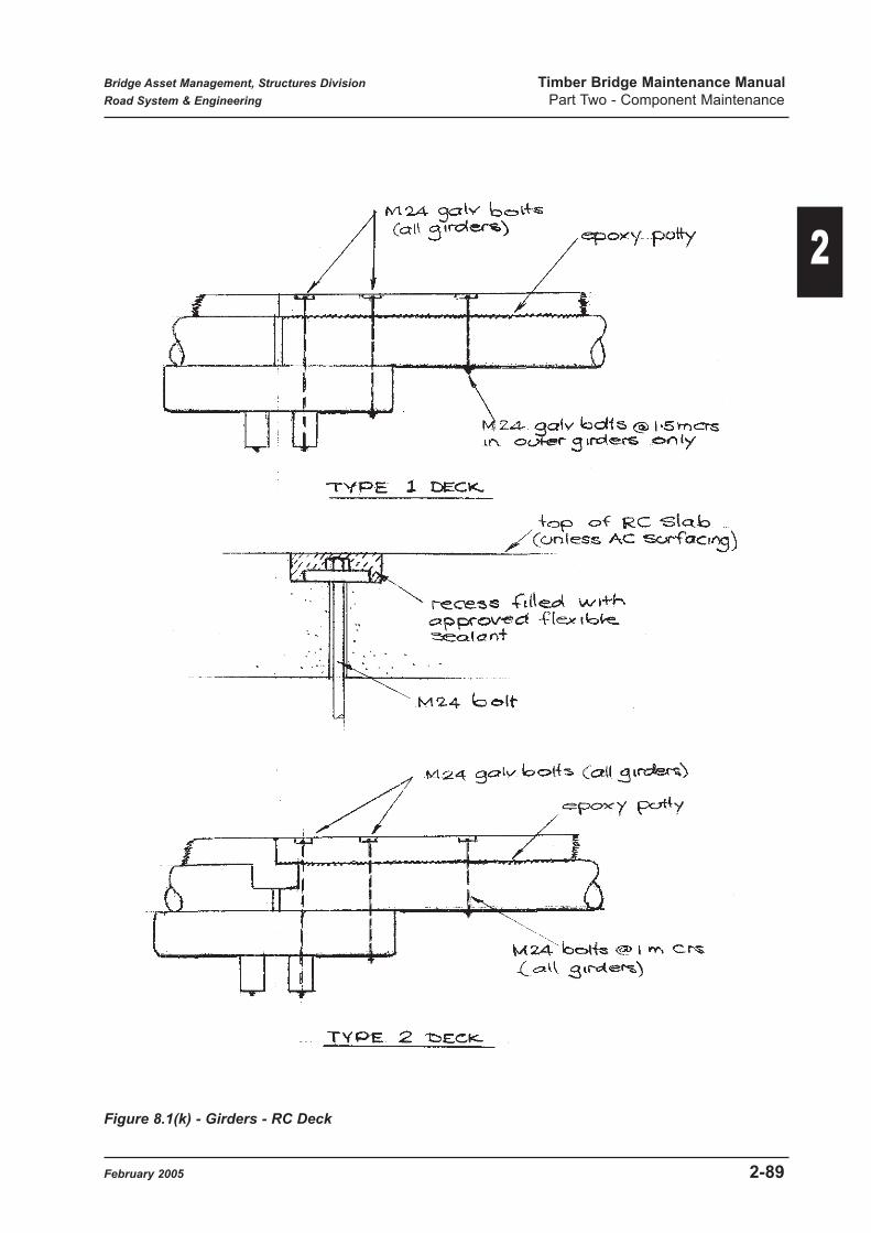
Figure 8.1(k) - Girders - RC Deck
Bridge Asset Management, Structures Division Timber Bridge Maintenance Manual
Road System & Engineering Part Two - Component Maintenance
February 2005 2-89
2

Though this procedure is recommended, the expected effective life of the CN Oil, particularly in
areas exposed to direct sunlight is not currently known, and monitoring will be needed to
determine rates of re-application. It should also be noted that although sawn octagonal girders
may be CCA treated before supply, the treatment is only effective in the residual sapwood
remnants. All surfaces should be treated as shown above. Where un-sapped CCA treated girders
are used, no additional surface treatment is considered necessary.
Although safety concerns associated with the use of CN and boron products are much less than
those with creosote, the manufacturers application and other safety requirements shall be strictly
followed.
Bridge Asset Management, Structures Division Timber Bridge Maintenance Manual
Road System & Engineering Part Two - Component Maintenance
2-90 February 2005
2

Figure 8.1(l) - Supplementary Members
Bridge Asset Management, Structures Division Timber Bridge Maintenance Manual
Road System & Engineering Part Two - Component Maintenance
February 2005 2-91
2

SEATING WIDTHS - GIRDERS
Figure 8.1(n) - Girder Seating Widths
Bridge
Width (m)O I C
Dia D
(mm)A(mm) B(mm) C(mm) Comments
'A' CLASS AT PIER (8.5 - 9.1M SPANS):-
3.66 0 - - 4.31 184 256 368 -
5.49 0 - - 4.31 184 256 368 -
6.1 0 - - 406 184 225 349 -
'A' CLASS AT ABUT (8.5 - 9.1 M SPANS):-
3.66 0 - - 431 184 341 327 83 snipe*
5.49 0 - - 431 184 341 327 83 snipe*
6.1 0 - - 406 184 320 305 79 snipe*
'A' CLASS AT PIER (8.5 - 9.1 M SPANS):-
3.66 - I - 482 102 219 451 -
5.49 - I - 482 102 219 451 -
6.1 - I - 457 102 196 428 -
'A' CLASS AT ABUT (8.5 - 9.1 M SPANS):-
3.66 - I - 482 102 166 463 -
5.49 - I - 482 102 166 463 -
6.1 - I I 457 102 136 441 -
'A' CLASS AT PIER (8.5 - 9.1 M SPANS):-
3.66 - - - - - - - -
5.49 - - C 482 102 192 457 -
6.1 - - C 457 102 167 435 -
'A' CLASS AT ABUT (8.5 - 9.1 M SPANS):-
3.66 - - - - - - - -
5.49 - - C 482 102 124 470 -
6.1 - - C 457 102 86 447
'A' CLASS AT PIER (7.3 - 8.2 M SPANS):-
3.66 0 - - 406 184 225 349 -
5.49 0 - - 406 184 225 349 -
6.1 0 - - 381 184 240 314 -
'A' CLASS AT ABUT (7.3 - 8.2 M SPANS):-
3.66 0 - - 406 184 320 305 79 snipe*
5.49 0 - - 406 184 320 305 79 snipe*
6.1 0 - - 381 184 311 276 80 snipe*
O = outer
I = inner
C = centre
Dim 'A' for outer girder is taken as average based on specified seating limits
* indicates snipe depth exceeds limit for no strengthening
Bridge Asset Management, Structures Division Timber Bridge Maintenance Manual
Road System & Engineering Part Two - Component Maintenance
2-92 February 2005
2

Figure 8.1(n) - Girder Seating Widths
Bridge
Width (m)O I C
Dia
D(mm)A(mm) B(mm) C(mm) Comments
'A' CLASS AT PIER (7.3 - 8.2 M SPANS):-
3.66 - I - 457 102 196 428 -
5.49 - I - 457 102 196 428 -
6.1 - I - 432 102 222 394
'A' CLASS AT ABUT (7.3 - 8.2 M SPANS):-
3.66 - I - 457 102 136 441 -
5.49 - I - 457 102 136 441 -
6.1 - I - 432 102 141 413 -
'A' CLASS AT PIER (7.3 - 8.2 M SPANS):-
3.66 - - - - - - - -
5.49 - - C 457 102 167 435 -
6.1 - - C 432 102 202 400 -
'A' CLASS AT ABUT (7.3 - 8.2 M SPANS):-
3.66 - - - - - - - -
5.49 - - C 457 102 86 447 -
6.1 - - C 432 102 100 419 -
'A' CLASS AT PIER (7.0 M SPAN):-
3.66 0 - - 381 184 240 314 -
5.49 0 - - 381 184 240 314 -
6.1 0 - - 355 184 227 289 -
'A' CLASS AT ABUT (7.0 M SPAN):-
3.66 0 - - 381 184 311 276 80 snipe*
5.49 0 - - 381 184 311 276 80 snipe*
6.1 0 - - 355 184 289 254 77 snipe*
'A' CLASS AT PIER (7.0 M SPAN):-
3.66 - I - 432 102 222 394 -
5.49 - I - 432 102 222 394 -
6.1 - I - 406 102 196 374
'A' CLASS AT ABUT (7.0 M SPAN):-
3.66 - I - 432 102 141 413 -
5.49 - I - 432 102 141 413 -
6.1 - I - 406 102 118 390 -
Bridge Asset Management, Structures Division Timber Bridge Maintenance Manual
Road System & Engineering Part Two - Component Maintenance
February 2005 2-93
2

Figure 8.1(o) - Girder Seating Widths
Bridge
Width (m)O I C
Dia D
(mm)A(mm) B(mm) C(mm) Comments
'A' CLASS AT PIER (7.0 M SPAN):-
3.66 - - - - - - - -
5.49 - - C 432 102 202 400 -
6.1 - - C 406 102 168 381 -
'A' CLASS AT ABUT (7.0 M SPAN):-
3.66 - - - - - - - -
5.49 - - C 432 102 100 419 -
6.1 - - C 406 102 68 397 -
'A' CLASS AT PIER (6.1 - 6.7 M SPANS):-
3.66 0 - - 355 184 227 289 -
5.49 0 - - 355 184 227 289 -
6.1 0 - - - - - - -
'A' CLASS AT ABUT (6.1 - 6.7 M SPANS):-
3.66 0 - - 355 184 289 254 77 snipe*
5.49 0 - - 355 184 289 254 77 snipe*
6.1 0 - - - - - - -
'A' CLASS AT PIER (6.1 - 6.7 M SPANS):-
3.66 - I - 406 102 196 374 -
5.49 - I - 406 102 196 374 -
6.1 - I - - - - - -
'A' CLASS AT ABUT (6.1 - 6.7 M SPANS):-
3.66 - I - 406 102 138 387 -
5.49 - I - 406 102 138 387 -
6.1 - I - - - - - -
'A' CLASS AT PIER (6.1 - 6.7 M SPANS):-
3.66 - - - - - - - -
5.49 - - C 406 102 168 381 -
6.1 - - C - - - - -
'A' CLASS AT ABUT (6.1 - 6.7 M SPANS):-
3.66 - - - - - - - -
5.49 - - C 406 102 68 397 -
6.1 - - C - - - - -
Bridge Asset Management, Structures Division Timber Bridge Maintenance Manual
Road System & Engineering Part Two - Component Maintenance
2-94 February 2005
2
8.2 Steel Girders
Refer to BIM Appendix D for a description of the four condition states applicable to this
component.
Purpose:
The main function of steel girders is to transfer both the self weight of a span and also vertical and
longitudinal traffic loads to the substructure. They also act to distribute transverse loads such as
wind and flood debris forces to the pier supports.
Significance: Significance Rating 4
Girders are primary structural members and form probably the most critical component of a bridge
superstructure. In the event of a girder failure, the consequence of a failure can vary from deck
surface deformation to complete span collapse. The outcome depends on the degree of
redundancy on redistribution of loads in the bridge, which depends on location and number of
girders and the condition of the overlying decking and its ability to span to adjacent girders.
Details:
A small number of steel girder bridge superstructures were built on timber piers and abutments
while substitution of steel girder for individual timber girders has also occurred in some past
maintenance jobs. As noted in Part 1 Section 6.2, a superstructure design consisting of steel
girders with a plywood deck has been developed for use as a full span replacement option on
timber bridges. Figure 8.2 shows general details of this and other steel girder usage.
Failure Mechanism
Steel girders will generally fail in bending at the centre of the span as the result of yielding of the
lower girder flange, most likely as the result of gross overload, though corrosion could reduce
section capacity causing failure at normal loadings. As well, if the top girder flange is not
adequately laterally supported by the decking, lateral buckling may occur, drastically reducing
bending capacity.
Maintenance Activities:
Refer to Part 3 Item 2.22 (22S) for recommended maintenance practices applicable to the various
expected deterioration states for this component.
Maintenance Activity Numbers Units
22S1 Strengthen steel girder Each
22S2 Install top flange restraints Lump sum
22S3 Straighten steel girder Each
22S4 Replace timber girder with steel girder Each
22S5 Replace buckle area Lump sum
Bridge Inspection Manual Component No. 22S
Bridge Asset Management, Structures Division Timber Bridge Maintenance Manual
Road System & Engineering Part Two - Component Maintenance
February 2005 2-95
2

Refer to Part 4 for a description of applicable maintenance activities.
Figure 8.2 - Steel Girders
Bridge Asset Management, Structures Division Timber Bridge Maintenance Manual
Road System & Engineering Part Two - Component Maintenance
2-96 February 2005
2

8.3 Approved Alternative Girders
This component is currently under development as an alternative girder member, which may be
substituted for individual timber girders.
Once a suitable alternative girder has been approved, the 4 condition states applicable to this
member will be included in Appendix D of BIM.
9.0 Corbels
9.1 Timber Corbels (27T)
Refer to BIM Appendix D for a description of the four condition states applicable to this
component.
Purpose:
The main function of a timber corbel member is to support the ends of timber girders at piers
transferring vertical and horizontal girder loads to the headstock. Timber corbels are not normally
incorporated at abutments, and where found, are generally the result of a bridge shortening
process.
Traditionally, effective shortening of girder spans due to corbel support has not generally been
considered for capacity analysis due to general timber member looseness reducing any continuity
benefits at piers. This is being reconsidered pursuant to recent research findings.
The rationale behind the use of corbels was to reduce the potential for girder collapse at pier ends,
thereby extending timber girder life. Where the ends of girders are severely rotted, a supporting
corbel allows the transfer of girder loads to take place further out from the region of the relatively
narrow pier headstock. For this interaction to work, however, the corbel itself requires sufficient
supporting capacity.
Maintenance Activity Numbers Units
27T1 Strengthen corbel Each
27T2 Replace timber corbel Each
Bridge Inspection Manual Component No. 27T
Maintenance Activity Numbers Units
22O1 Replace girder with approved alternative girder Each
Future Bridge Inspection Manual Component No. 22O
Bridge Asset Management, Structures Division Timber Bridge Maintenance Manual
Road System & Engineering Part Two - Component Maintenance
February 2005 2-97
2
Significance: Significance Rating 3
Though not a primary structural member, the consequences of corbel failure could vary from the
settlement of the supported girder to the girder end dropping off the head stock, resulting in bridge
unserviceability and closure.
Details:
Timber corbels consist of round log or sawn octagonal members of generally standardized lengths
and diameters depending on location and bridge class. Figure 9.1(a) shows typical details
normally found. Some variations have occurred in longer span bridges, where longer or doubled
corbels have been used to try to reduce the effective span length of the girders.
Failure Mechanism:
Lack of end treatment or maintenance thereof leads to susceptibility to insect or fungal attack and
timber corbels will generally fail by crushing or collapse as a result of loss of section due to
piping, generally combined with severe longitudinal splitting. Bending failure may occur if
excessive notching at headstock seating locations has taken place.
Materials:
Refer to Specification MRS 11.87 for acceptable species and properties for timber corbels.
Corbels may be supplied as
(a) Naturally round timber with sapwood removed.
(b) Octagonally sawn members.
Maintenance Activities:
Refer to Part 3 Item 2.24 (27T) for recommended maintenance practices applicable to the various
expected deterioration states for the component.
Refer to Part 4 for a description of applicable maintenance activities.
Further considerations and detailed explanations are as follows:-
Routine Maintenance:
Routine or preventative maintenance activities for timber corbels will generally be identified and
carried out during Level 1 bridge inspections. These activities would be:-
• Tightening or replacing corbel / headstock bolts.
• Application of surface preservatives or waterproofing agents.
Headstock attachment bolts should be checked for tightness as this reduces potential movement
or rocking of the corbel on the headstock.
Where corrosion of attachment bolts is noted, they should be noted for later programmed
maintenance.
Bridge Asset Management, Structures Division Timber Bridge Maintenance Manual
Road System & Engineering Part Two - Component Maintenance
2-98 February 2005
2

Figure 9.1(a) - Timber Corbels
Bridge Asset Management, Structures Division Timber Bridge Maintenance Manual
Road System & Engineering Part Two - Component Maintenance
February 2005 2-99
2

Where surface rotting is detected, an application of chemical preservative should be made to the
effected surfaces to try and slow the fungal attack. Sealant on the ends of the corbels should also
be checked and replenished where required. Refer to Section 17.7 for recommended materials.
Additional preventative maintenance actions for timber corbels will take the form of close
monitoring during site visits for signs of termite infestations, such as trails or activity in cracks or
joints between corbel an girder. Termite activity should be treated as soon as possible after
discovering before excessive damage can be done. Refer to Section 17.8 for further details.
Programmed Maintenance:
Any corbel which is identified by inspection as being in Condition State 4, will generally have lost
sufficient Section due to decay or termite attack, that the probability of collapse under traffic loads
is greatly increased. Corbels in this condition should be replaced.
Where severe deterioration has occurred in the extreme corbel ends only, there may be potential
for continuing load transfer between the girder and corbel, however. Figure 8.1(b) (1) shows this
situation, which has the effect of extending the time before replacement is necessary. BAM will
give advice on this situation if requested.
The main considerations for corbel replacement are:-
(1) Corbel sizes required
(2) Corbel trimming and snipes.
The size of a replacement corbel generally corresponds to that of the girder sizes which are shown
in Figure 3.4(b) (Part 1). Length generally depends on bridge design class, but must also be as
shown on the specific bridge drawings, as modified lengths or numbers of corbels (vertically) also
were not uncommon. Where an increased size outer girder is to be incorporated, generally the
corbel size may correspond. However, because corbels are not full structural members, some
modification of size may occur to ease assembly.
Trimming of the top and bottom surfaces of the corbel for contact with the girder and headstock
helps reduce bearing stresses to acceptable levels. No minimum widths have ever been detailed
but the horizontal seating widths obtained for 'A' Class round girders are shown in Figures 9.1(c)
& (d) for information.
Notching (or sniping) of the central support area of the corbel for seating on the headstock is
required, but care must be taken not to cut away excessive amounts of timber in this process.
Section 4.6 (Part 1) briefly discusses requirements for snipes in corbels.
It is recommended that sniping be limited 25% of the corbel depth in order to allow sufficient
bending strength over the headstock area to support the loads from the girders. Figure 9.1(b) (1)
shows these requirements.
Bridge Asset Management, Structures Division Timber Bridge Maintenance Manual
Road System & Engineering Part Two - Component Maintenance
2-100 February 2005
2

Figure 9.1(b) - Corbel Details
Bridge Asset Management, Structures Division Timber Bridge Maintenance Manual
Road System & Engineering Part Two - Component Maintenance
February 2005 2-101
2

SEATING WIDTHS - CORBELS
Figure 9.1(c) - Corbel Seating Widths
Bridge
Width (m)O I C
Dia D
(mm)A(mm) B(mm) C(mm) Comments
'A' CLASS (8.5 - 9.1 M SPANS):-
3.66 0 - - 431 202 202 381 -
5.49 0 - - 431 202 202 381 -
6.1 0 - - 406 201 201 352 -
3.66 - I - 482 206 206 435 -
5.49 - I - 482 206 206 435 -
6.1 - I - 457 204 204 409 -
3.66 - - - - - - - -
5.49 - - C 482 206 206 435 -
6.1 - - C 457 204 204 409 -
'A' CLASS (7.3 - 8.2 M SPANS):-
3.66 0 - - 406 201 201 352 -
5.49 0 - - 406 201 201 352 -
6.1 0 - - 381 210 210 317 -
3.66 - I - 457 204 204 409 -
5.49 - I - 457 204 204 409 -
6.1 - I - 432 214 214 374 -
3.66 - - - - - - - -
5.49 - - C 482 204 204 409 -
6.1 - - C 457 214 214 374 -
'A' CLASS (7.0 M SPAN):-
3.66 0 - - 381 210 210 317 -
5.49 0 - - 381 210 210 317 -
6.1 0 - - 355 202 202 292 -
3.66 - I - 432 214 214 374 -
5.49 - I - 432 214 214 374 -
6.1 - I - 406 219 219 343 -
3.66 - - - - - - - -
5.49 - - C 432 214 214 374 -
6.1 - - C 406 219 219 343 -
O = outer
I = inner
C = centre
Note: 'A' and 'B' have been made equal
Bridge Asset Management, Structures Division Timber Bridge Maintenance Manual
Road System & Engineering Part Two - Component Maintenance
2-102 February 2005
2

SEATING WIDTHS - CORBELS
Figure 9.1(d) - Corbel Seating Widths
Where existing details are such that snipe depths would exceed the above requirements, contact
BAM for advice. A strengthening procedure such as shown in Figure 9.1(b) (3) may be possible.
Where new corbels are supplied with a pre-existing pipe, (up to 35mm allowed), this shall be
plugged before erection as shown in Figure 9.1(b) (2). The ends of corbel shall be neatly trimmed
as shown in Figure 9.1(a).
Where corbels are supplied with longitudinal cracks exceeding 10mm in width, anti-splitter bolts
shall be installed to reduce further tendency to split. Refer to Figure 17.1(d) for recommended
details.
Before corbel erection, the ends shall be treated with a timber preservative and a thick grease
applied (refer to Figure 17.7). Where sawn octagonal corbels are supplied, an end nailing plate
shall be attached as shown a Figure 9.1(a). Nail plates are recommended on the ends of all corbels
irrespective of section.
All contact surfaces between the new corbel and girders or headstock shall be treated with a
preservative, grease and a bituminous felt placed.
The general corbel replacement procedure would be:-
• Prop overlying girder to remove all load from the corbel.
• Remove or cut out corbel / girder and corbel / headstock bolts. This will generally require
lifting of kerbs and overlying deck planks.
Bridge
Width (m)O I C
Dia D
(mm)A(mm) B(mm) C(mm) Comments
'A' CLASS (6.1-6.7M SPANS)
3.66 0 - - 355 227 227 289 -
5.49 0 - - 355 227 227 289 -
6.1 0 - -
3.66 - I - 406 219 219 343 -
5.49 - I - 406 219 219 343 -
6.1 - I -
3.66 - - - - -
5.49 - - C 406 219 219 343
6.1 - - C
O = outer
I = inner
C = centre
Bridge Asset Management, Structures Division Timber Bridge Maintenance Manual
Road System & Engineering Part Two - Component Maintenance
February 2005 2-103
2

• Remove defective corbel.
• Installation of new corbel including drilling and bolt assembly. If existing bolt holes cannot
be reused, a modified hold down to the headstocks may be required.
• Remove jacks to transfer loads back on to corbel.
• Replace deck planks and kerbs and DWS where required.
9.2 Concrete Corbels (27C)
Refer to BIM Appendix D for a description of the four condition states applicable to this
component.
Purpose:
The main function of a concrete corbel is to support the ends of timber girders at piers (and
possibly abutments), helping to transfer girder loads to the headstocks. Effective shortening of
girder spans due to corbel support is considered to occur.
Significance: Significance Rating 3
Concrete corbels were sometimes used with concrete substructures to provide the same function
as timber corbels, i.e. to reduce the potential for girder collapse at the ends, thereby extending
timber girder life. Where the ends of timber girders are severely rotted, a supporting corbel allows
the transfer of girder loads to take place further out from the normally narrow headstock. The
concrete corbel is not a primary structural member and failure should not lead to bridge
serviceability problems (provided the girder end is sufficiently sound) as load will now transfer
directly to the headstock area. Where girder ends are rotted, however, girder failure could still
occur outside the limit of the deteriorated corbel.
Details:
Figure 9.2 shows typical details used for concrete corbels, which are used on concrete piers.
Failure Mechanism:
The most common form of defect found is spalling due to either corrosion of reinforcement or due
to superstructure induced edge loading. Significant spalling may reduce support area for the
corbel. If the end of the girder is sound, vertical loads will transfer through and area closer to the
pier stem. If there is also crushing occurring in the girder end, there could be a significant girder
settlement.
Maintenance Activity Numbers Units
Refer to general concrete repair Activities
Bridge Inspection Manual Component No. 27C
Bridge Asset Management, Structures Division Timber Bridge Maintenance Manual
Road System & Engineering Part Two - Component Maintenance
2-104 February 2005
2

Maintenance Activities:
Refer to Part 3 Item 2.25 (27C) for recommended maintenance practices applicable to the various
expected deterioration states for this component.
Refer to Part 4 for a description of applicable maintenance activities.
Figure 9.2 - Concrete Corbels
Bridge Asset Management, Structures Division Timber Bridge Maintenance Manual
Road System & Engineering Part Two - Component Maintenance
February 2005 2-105
2

10.0 Headstocks
10.1 Timber Headstocks (54T)
Refer to BIM Appendix D for a description of the four condition states applicable to this
component.
Purpose:
The main function of headstock members is to transfer vertical and longitudinal loads from the
girders and corbels to substructure piles.
They also act in conjunction with diagonal bracing and wales to distribute horizontal loads such
as wind and debris forces through the substructure.
Significance: Significance Rating 4
Headstocks are primary structural members and form a critical component of piled substructures.
Failure of headstock members will lead to partial collapse and unserviceability of the complete
structure.
Details:
The most common form of headstock is an open type, consisting of double members in sawn
hardwood, notched into and bolted to the top of the timber piles. This configuration was adopted
for ease of member replacement. Note that vertical load transfer to the pile is meant to be through
bearing on the pile notch rather than through shear of the connection bolts.
Figure 10.1(a) shows the general details for this type of headstock. Member sizes have been
standardized depending on the design class of the bridge, and these must be adhered to as
minimum sizes.
An alternative solid headstock which could be a sawn, hewn or round log member was also used
in early bridges, but very few of these now remain. In these, the headstock was morticed to fit
over tenons on the pile tops, as shown in Figure 10.1(b).
Maintenance Activity Numbers Units
54T1 Place supplementary member Lump sum
54T2 Reconstruct splice Each
54T3 Relocate headstock Each
54T4 Jack girders or headstock to level Lump sum
54T5 Replace headstock in timber Each
54T6 Splice in new headstock section Each
Bridge Inspection Manual Component No. 54T
Bridge Asset Management, Structures Division Timber Bridge Maintenance Manual
Road System & Engineering Part Two - Component Maintenance
2-106 February 2005
2

Figure 10.1 (a) - Timber Headstocks - Open Type
Bridge Asset Management, Structures Division Timber Bridge Maintenance Manual
Road System & Engineering Part Two - Component Maintenance
February 2005 2-107
2

Figure 10.1(b) - Timber Headstock - Solid Type
Bridge Asset Management, Structures Division Timber Bridge Maintenance Manual
Road System & Engineering Part Two - Component Maintenance
2-108 February 2005
2

Failure Mechanism:
Because of the conventional arrangement of girders and piles in timber bridges, both bending and
shear are important considerations in headstocks, though most recorded failures appear to be
bending related.
In addition to Part 3 Item 2.26 (54T) for recommended maintenance practices applicable to the
various expected deterioration states for this component.
Though some headstock failures appear to be the result of a passage of a grossly overloaded
vehicle, in most cases, reduced member capacity caused by deterioration processes such as decay,
insect attack or fire, has led to an inability to support normal legal loads.
Horizontal cracking, particularly where it occurs across the full width of a member will also
significantly reduce a headstock member capacity. Bending failure will normally result in vertical
cracking over pile supports or under centrally placed girders.
Materials:
Refer to Main Roads Specification MRS 11.87 for acceptable timber species and properties for
timber headstocks.
There is currently widespread acceptance within Main Roads that central heart material should not
be present in sawn timber for open headstocks because of the potential for accelerated decay
within this region of the member. However, DMR Specifications up to the latest issue (circa
1950) specifically allowed the presence of heart in timber above decking size, proved it was not
exposed along the sides of the member.
It would appear that excluding heart material would be the most cost effective strategy
considering cost versus life of a headstock member.
However, it is noted that supply of large section sawn timber is becoming increasingly difficult to
secure. As well, back and quarter sawn timbers have the potential for significant warp or bowing
due to the differing rates of radial shrinkage (refer to Article 4.5) (Part 1). This can result in
assembly and seating difficulties. To overcome these problems, it is considered acceptable to
allow heart centrally in the headstock member, provided its width is increased to 200mm. In
addition, end protection in the form of a heavy application of grease or copper napthenate
emulsion should be applied and the end enclosed in a galvanised capping.
Refer to Article 6.4 (Part 1) for a discussion of alternative headstock materials such as steel section
or plywood (softwood) and their acceptability for maintenance work.
Maintenance Activities:
Refer to Part 3 Item 2.26 (54T) for recommended maintenance practices applicable to the various
expected deterioration states for this component.
Refer to Part 4 for a description of applicable maintenance activities.
Bridge Asset Management, Structures Division Timber Bridge Maintenance Manual
Road System & Engineering Part Two - Component Maintenance
February 2005 2-109
2

Figure 10.1(c) - Headstock Splicing
Bridge Asset Management, Structures Division Timber Bridge Maintenance Manual
Road System & Engineering Part Two - Component Maintenance
2-110 February 2005
2

Further consideration and detailed explanations are as follows:-
Routine Maintenance
Routine or preventative maintenance actions for timber headstocks will generally be identified
and carried out during Level 1 bridge inspections. These activities would be:
• Tightening or replacing headstock/pile bolts
• Application of surface preservatives or waterproofing agents
• Emergency propping of cracked or sagging headstock member, or checking existing
propping for tightness
The pile attachment bolts should be checked for tightness as this will prevent possible differential
movement between headstock and pile. Where corrosion of bolts is evident, they should be
withdrawn and replaced by galvanised bolts of the same diameter if loss of section is evident. The
bolt holes through the headstock should be coated/packed with CN Emulsion or thick grease
before bolt insertion. Adjacent seating of the headstock on the pile notch should be checked.
The tin caps at the ends of the headstocks should be removed to check for signs of decay or severe
splitting and drying out of the previous end treatment. For headstocks determined to be in
Condition State 4, replacement should be programmed. Up to CS3, however, end treatment with
CN emulsion and petroleum jelly or grease should be carried out and the tin cap replaced.
Where a headstock is found to have broken, sagged noticeably or has other severe structural
defects, emergency tomming may be used to allow continued operation of the bridge. Figure
17.11(a) shows typical prop details.
A number of alternative propping arrangements have been used to temporarily (often long term in
practice) support failing headstock members. Figure 17.11(a) shows a number of these, which, in
general, will be carried out subsequent to the Level 1 inspection.
Programmed Maintenance
Headstocks in Condition State 4 will have significantly reduced capacity and must be
programmed for replacement, or alternatively a new replacement section spliced to an acceptable
portion of the length. In general, replacement of the full length of a headstock member is
recommended as this provides maximum member strength and reduces the number of potential
areas of deterioration. Where splicing of a new section is used, details shall be generally as shown
in Figure 10.1(c). Note that splicing away from a pile support has been used as a standard detail
and may be retained if it appears to be functioning satisfactorily. Contact surfaces and end
sections of timber components at the splice must be treated with a timber preservative such as CN
oil before assembly.
As an alternative, replacement of a defective headstock with a steel member may also be
considered, particularly if there is difficulty in obtaining timber material Refer Article 6.4 (Part 1)
and Section 10.2.
General procedures to carry out member replacement would be:
• Prop the girders/corbels to relieve loads on the headstock. Particular attention should be
given to bracing the props to prevent slippage, especially if loads are being allowed to use
Bridge Asset Management, Structures Division Timber Bridge Maintenance Manual
Road System & Engineering Part Two - Component Maintenance
February 2005 2-111
2

the bridge while it is being repaired. In general it is considered safer to close the bridge, if
possible, during headstock replacement.
• The girders/corbels then need to be raised slightly to allow pile/headstock bolting to be
undone and the defective headstock removed.
• The new headstock section needs to be slipped into position & drilled, the bolts coated with
grease and retightened. The new headstock needs to bear on the pile notch, or steel packers
installed to provide direct bearing support. All contact surfaces should be treated with a
preservative and grease, and a bituminous felt placed.
• The props are then removed, allowing the girders/corbels to bear on the headstocks again.
Where the headstock is showing minor cracking but is considered to be only Condition State 3,
strengthening of the member may be carried out. One solution is to provide a new headstock
member immediately below and supporting the deteriorated member as shown in Figure 10.1(d).
The general procedure is:
• The piles beneath existing headstock should be progressively cut, chiseled out and an
additional headstock slipped in below the existing member. The new headstock bolts to the
piles should be in a different line to those above, to prevent excessive splitting of the pile
top. All contact surfaces should be treated with preservative and grease.
• The new headstock should bear hard against the existing headstock as well as the pile notch
for good bearing support rather than the bolts providing physical support.
• The additonal support will allow the original headstock to withstand loads placed on it.
Longitudinal cracking on headstock sides has the potential to markedly effect bending and shear
capacity if the crack extends the full width of the section. As an example, a full width crack at ½
depth reduces bending strength to ½ that of the solid section. The strength of the member may be
reinstated by a full or part length steel plate bolted as shown in Figure 10.1(d). The steel plate is
to be galvanised, and preservative such as CN oils is to be placed on the contact area of the timber
before assembly.
Additional:
Standard drawings require bracing to be let 25mm into the soffit of headstock members,
potentially reducing member strength. A 25mm notch, taken full width reduces bending strength
by 16% and shear strength by 9%. Care should be taken to limit such cuts in headstock members
to the minimum specified.
Where headstocks have sagged up to 50mm, as a result of pile settlements, the girders should be
jacked back to level and shims placed between the headstocks and corbels as shown in Figure
10.1(e).
For larger headstock sags, and if it can be determined that pile settlement is not continuing, the
headstock bolts may be released and the headstock jacked back to level. Packing is then placed
below the headstock as shown in Figure 10.1(e) to maintain level.
Any sagging in a headstock effectively reduces its capacity in bending and shear.
Bridge Asset Management, Structures Division Timber Bridge Maintenance Manual
Road System & Engineering Part Two - Component Maintenance
2-112 February 2005
2

Figure 10.1(d) Headstocks - Supplementary Supports
Bridge Asset Management, Structures Division Timber Bridge Maintenance Manual
Road System & Engineering Part Two - Component Maintenance
February 2005 2-113
2

Figure 10.1(e) - Restoring Headstock Levels
Bridge Asset Management, Structures Division Timber Bridge Maintenance Manual
Road System & Engineering Part Two - Component Maintenance
2-114 February 2005
2

10.2 Steel Headstocks (54S)
Refer to BIM Appendix D for a description of the four condition states applicable to this
component.
Purpose:
The main function of headstock members is to transfer vertical load from girders and corbels to
substructure piles.
They also act in conjunction with diagonal bracing and wales to distribute horizontal loads such
as wind and debris forces through the substructure.
Significance: Significance Rating 4
Headstocks are primary structural members and form a critical component of piled substructure.
Failure of headstock members will lead to unserviceability of the complete structures.
Details:
Steel headstocks were not, in general, originally used on timber bridges and where found, are
normally the result of maintenance replacement of the original timber members.
Steel headstocks are generally of a steel channel section, seated in the original pile notches and
clamped to the piles by bolts. Figures 10.2(b), (c) & (d) show recommended details for steel
headstock substitution. Figure 10.2(a), shows older details commonly found. Both headstocks
must be replaced in order to keep a constant stiffness for each member at a particular pier.
Failure Mechanism:
Steel headstocks will generally fail in bending either under a girder or over a pile support as a
result of material yielding in the flanges. This could be the result of gross overloading or the result
of significant section loss due to corrosion. Buckling of the top flange of the headstock is
considered unlikely.
Maintenance Activity Numbers Units
54S1 Relocate headstock Each
54S2 Replace steel headstock Each
54S3 Strengthen steel headstock Each
54S4 Replace timber headstock with steel alternative Each
54S5 Jack girders or headstock to level Lump sum
Bridge Inspection Manual Component No. 54S
Bridge Asset Management, Structures Division Timber Bridge Maintenance Manual
Road System & Engineering Part Two - Component Maintenance
February 2005 2-115
2
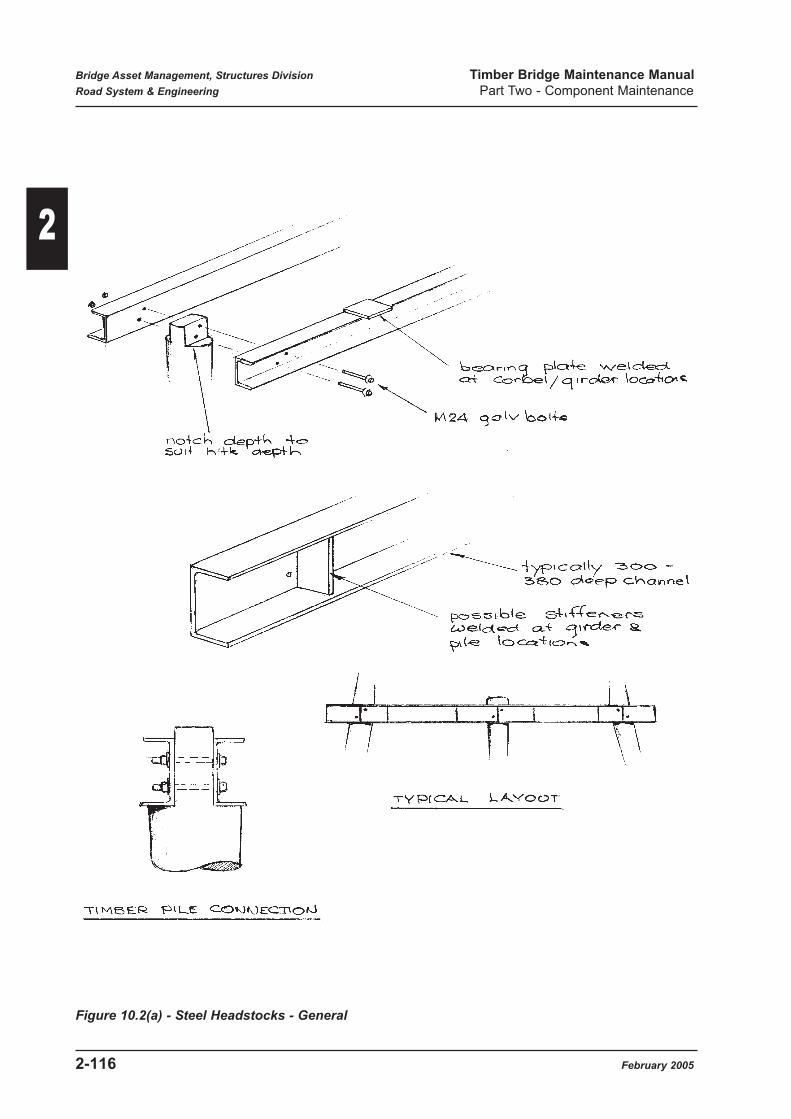
Figure 10.2(a) - Steel Headstocks - General
Bridge Asset Management, Structures Division Timber Bridge Maintenance Manual
Road System & Engineering Part Two - Component Maintenance
2-116 February 2005
2

Figure 10.2(b) - Steel Headstocks (1)
Bridge Asset Management, Structures Division Timber Bridge Maintenance Manual
Road System & Engineering Part Two - Component Maintenance
February 2005 2-117
2

Figure 10.2(c) - Steel Headstocks (2)
Bridge Asset Management, Structures Division Timber Bridge Maintenance Manual
Road System & Engineering Part Two - Component Maintenance
2-118 February 2005
2

Figure 10.2(d) - Steel Headstocks (3)
Bridge Asset Management, Structures Division Timber Bridge Maintenance Manual
Road System & Engineering Part Two - Component Maintenance
February 2005 2-119
2

Figure 10.2(e) - Steel Headstocks (4)
Bridge Asset Management, Structures Division Timber Bridge Maintenance Manual
Road System & Engineering Part Two - Component Maintenance
2-120 February 2005
2

Figure 10.2(f) - Steel Headstocks (5)
Bridge Asset Management, Structures Division Timber Bridge Maintenance Manual
Road System & Engineering Part Two - Component Maintenance
February 2005 2-121
2
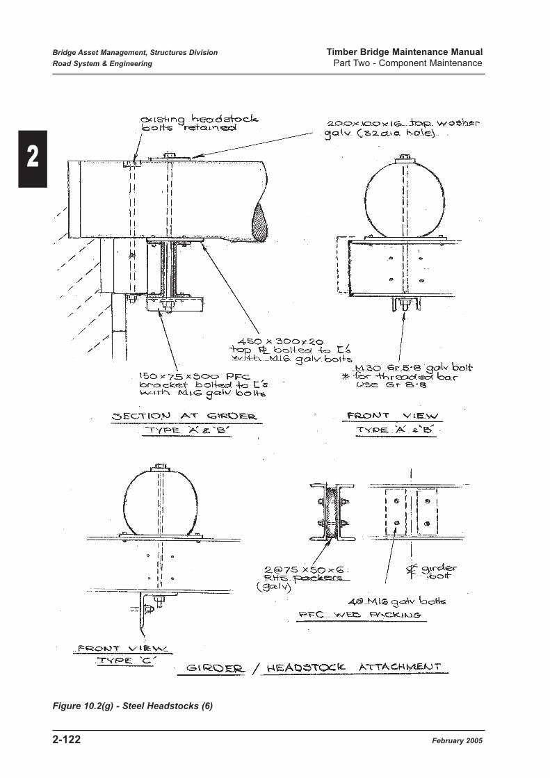
Figure 10.2(g) - Steel Headstocks (6)
Bridge Asset Management, Structures Division Timber Bridge Maintenance Manual
Road System & Engineering Part Two - Component Maintenance
2-122 February 2005
2

Figure 10.2(h) - Steel Headstocks (7)
Bridge Asset Management, Structures Division Timber Bridge Maintenance Manual
Road System & Engineering Part Two - Component Maintenance
February 2005 2-123
2

Figure 10.2(i) - Steel Headstocks
Bridge Asset Management, Structures Division Timber Bridge Maintenance Manual
Road System & Engineering Part Two - Component Maintenance
2-124 February 2005
2

Maintenance Activities:
Refer to Part 3 Item 2.28 (27S) for recommended maintenance practices applicable to the various
expected deterioration states for this component.
Refer to Part 4 for a description of applicable maintenance activities.
Further considerations are as follows:
Routine Maintenance:
Routine or preventative maintenance actions for existing steel headstocks will generally be
identified and carried out during Level 1 bridge inspections. These activities would be:-
• Tightening or replacing headstock / pile bolts
• Removal of any aggressive contamination.
The pile attachment bolts should be checked for tightness as this will prevent possible differential
movement between headstock and pile. Where corrosion of bolts is evident, they should be
withdrawn and replaced by galvanised bolts of the same diameter if loss of section is evident.
Programmed Maintenance:
Where it is proposed to use steel headstocks as an alternative to hardwood members, the details
shown in Figures 10.2(b), (c) & (d) are recommended. The details shown have been developed
to provide enhanced support and hold down capacities. Contact Structures Division to obtain
suitable details for a specific job. The fabricated headstock sections will generally be detailed as
galvanised, but Districts may request unpainted surfaces if climate or short time service life will
safely allow this. Any galvanised surfaces damaged by site drilling etc. should have a cold
galvanising product applied.
Work operations will generally be:-
• Jack corbels and girders to remove all load from the headstock.
• Release all bolts and remove timber headstocks. Where hold down bolts cannot be
removed, they should be cut off.
• Trim corbel seating to take top plate.
• Deepen pile recesses to take depth of new steel headstock.
• Install new headstocks and bolt to piles.
• Attach M30 hold down bolts and brackets.
• Drill holes for girder / corbel bolts as required. If new girders are being replaced care should
be exercised to stabilise the girder on the corbels prior to bolting down. Removal of kerbs
may be necessary for this operation as well.
• Replace kerbs if required, and remove jacks to allow all load to be taken on the new
headstock.
The contact surfaces with the pile notch and the corbel / girder shall be treated with a preservative
and grease, and a bituminous felt placed to remove air gaps.
Bridge Asset Management, Structures Division Timber Bridge Maintenance Manual
Road System & Engineering Part Two - Component Maintenance
February 2005 2-125
2

The details shown in Figures 10.2(e) to (h) may be used to place steel headstocks at abutments
where the rear timber headstock remains in place. This removes the need for excavation behind
the abutment. Some additional preservative and termite treatment should be applied to the
exposed faces of the remaining headstock because future access will be restricted.
Work operations would be:-
• Measure locations of piles and girders and adjust attachment details as required.
• Jack girders to remove load from existing headstocks.
• Release all bolts and remove front headstock.
• Cut and trim pile heads as detailed.
• Assemble PFC members with top plates and brackets, and spray expanding foam protection.
• Erect steel headstock assembly and install headstock / pile and girder / headstock attachment
bolts.
The details shown in Figure 10.2(e) to (h) are based on theoretical plan dimensions and may not
cover all situations. Prior to ordering materials the location of girders with respect to the piles
should be measured. Where there are wide departure from the standard drawings, advice should
be sought from Bridge Asset Management for consideration of further details.
Figure 10.2(i) shows photographs of steel headstock installation.
Refer to Appendix B for typical bridge drawings showing steel headstocks.
Bridge Asset Management, Structures Division Timber Bridge Maintenance Manual
Road System & Engineering Part Two - Component Maintenance
2-126 February 2005
2

10.3 Concrete Headstocks (54C)
Refer to BIM Appendix D for a description of the four condition states applicable to this
component.
Purpose:
The main function of the headstock is to transfer vertical load from girder and corbels to
substructure piles, columns or walls. Transverse loads such as wind and debris, and longitudinal
loads such as braking are also transferred from the deck to the supporting structure below.
Concrete capping on masonry walls is used to provide a neat and levelled superstructure support
area and to transfer vertical loads to the masonry below.
Significance: Significance Rating 4
Discrete headstocks are primary structural members and form a critical component of piled or
columned substructure. Cantilevered headstock sections protruding from solid wall piers are also
critical components. Failure of these members will lead to unserviceability of the structure.
Failure Mechanism:
Where headstocks are continuously supported on a stem wall, the most extreme defect expected
will be localized spalling below girder support areas or cracking resulting from construction joint
shrinkage opening. Depending on location and extent, these defects may compromise load
transfer to the substructure, but will generally not lead to total unserviceability of the structure.
Other structural forms of concrete headstocks are uncommon in timber bridges. Refer to the
Bridge Maintenance Manual for further discussion.
Details:
Figure 10.3 shows details of various in-situ concrete headstocks which have been used in timber
bridge construction. Also shown is a procedure for spall repair below bearing areas.
Maintenance Activities:
Refer to Part 3 Item 2.27 (54C) for recommended maintenance practices applicable to the various
expected deterioration states for this component.
Refer to Part 4 for a description of applicable maintenance activities.
Maintenance Activity Numbers Units
54C1 Strengthen headstock Each
Bridge Inspection Manual Component No. 54C
Bridge Asset Management, Structures Division Timber Bridge Maintenance Manual
Road System & Engineering Part Two - Component Maintenance
February 2005 2-127
2

Figure 10.3 - Concrete Headstocks
Bridge Asset Management, Structures Division Timber Bridge Maintenance Manual
Road System & Engineering Part Two - Component Maintenance
2-128 February 2005
2

10.4 Concrete Packer (54C, 54P)
Refer to BIM Appendix D for a description of the four condition states applicable to this
component.
Purpose:
Both precast and in-situ concrete packers are used to establish or vary deck levels on existing
bridges.
Precast concrete members have been used on top of existing timber substructures where a
replacement superstructure has a reduced depth such as with stress-laminated timber slab decks.
In-situ concrete blocks, poured on top of existing timber headstocks, have been used to raise deck
levels while retaining existing superstructure components.
Significance: Significance Rating 2
The function of packer members is to transfer loads between adjacent sections of structure and as
such are not considered to be structural members. However, where the depth of the concrete
packer is structurally significant, for example, 500m or greater, the member is very much stiffer
than the supporting timber headstock. As a result, the packing member itself would effectively
provide the main pathway for transfer of superstructure loads into the piles. If the packer failed,
however, it would loose structural significance as the original timber headstock could resume the
status of primary structural member. Packers placed on top of rigid concrete stem substructure
would have no structural importance.
Details:
Figure 10.4 shows typical details of packer members like to be found on timber bridges.
Maintenance Activities:
Refer to Part 3 Item 2.29 (54P, 54C) for recommended maintenance practices applicable to the
various deterioration states for this component.
Refer to Part 4 for a description of applicable maintenance activities.
Maintenance Activity Numbers Units
Refer to general concrete repair Activities
Bridge Inspection Manual Component No. 54P, 54C
Bridge Asset Management, Structures Division Timber Bridge Maintenance Manual
Road System & Engineering Part Two - Component Maintenance
February 2005 2-129
2

Figure 10.4 - Concrete Packers
11.0 Piles
11.1 Timber Piles (56T
Refer to BIM Appendix D for a description of the four condition states applicable to this
component.
Purpose:
The main function of timber piles is to transfer vertical loads from span self weight and traffic into
the ground foundation. Other axial loads which may include uplift forces are induced by lateral
wind and flood debris loads. These loads, together with longitudinal traffic braking forces also
induce bending in the pile members. The use of pier bracing and wales helps reduce the amount
of bending incurred in the direction of stream flow.
Maintenance Activity Numbers Units
56T1 Replace timber pile Each
56T2 Splice timber pile Each
56T3 Place supplementary member Lump sum
56T4 Provide banding Lump sum
Bridge Inspection Manual Component No. 56T
Bridge Asset Management, Structures Division Timber Bridge Maintenance Manual
Road System & Engineering Part Two - Component Maintenance
2-130 February 2005
2

Significance: Significance Rating 4
Piles may be considered to be primary structural members and form a critical component of the
substructure. Failure of a pile will require all loads it supports to be redistributed through the
headstock to other members. Depending on pile location and headstock soundness the result
could vary from deck surface settlements to partial collapse of the superstructure. Likewise, loss
of pile section in a significant number of piles in a pier, such as from marine borer attack can (and
has) lead to complete pier collapse, under a heavy load or flooding.
Details:
Timber piles consist of natural round logs which have been debarked, but with sapwood left on
for added protection. There is generally an obvious natural taper in these members, with top
dimensions standardized depending on bridge design class. Driven piles are the most common
type and metal piles shoes are generally fitted to pile tips before driving. Generally a minimum
penetration of 5 metres was required to withstand the expected bridge loads and provide scour
protection. Where ground testing indicated less penetration due to very firm ground or rock, piles
were often supported on timber sill beams as shown in Figure 13.1, or were planted in preformed
holes.
Once piles are in place, they are notched to accept other components such as headstocks and
bracing.
Where rock was close to the surface, a common form of base support for pier piles was the
concrete sill as shown in Figure 13.2. This was essentially a concrete footing with tie-downs for
the shortened timber piles. Typical timber pile details are shown in Figure 11.1(a).
Other pile types which do not affect the load carrying ability of a bridge are strut & fender piles
which help stabilise a structure under flood, and wing piles.
Failure Mechanism:
In timber bridges, piles are essentially columns which function as compression members. Where
they are unable to support axial load due to section loss, they will fail in compression. Where
there are very large pipes and significant longitudinal splitting, the individual pile segments act as
slender columns which may fail in buckling mode, further reducing pile capacity from that
determined by residual pile area alone.
If bracing is ineffective due to rotting or bolt loss, the large forces from flood debris may cause
piles to fracture due to bending failure.
This can contribute to total structure loss under flood. Uplift failure of upstream piles due to
reduced hold down resulting from scour or hold down bolt failure on sills is probably also a major
factor in bridge loss.
However, pier piles are unlikely to fail in bending if the bracing system is adequate, and pile
condition is sound. It is possible for abutment piles to fail in bending if excessive earth pressure
loads are applied to piles. This may happen if long lengths of piles are exposed by scour and
particularly if a considerable depth of backing slabs exists or is added.
Bridge Asset Management, Structures Division Timber Bridge Maintenance Manual
Road System & Engineering Part Two - Component Maintenance
February 2005 2-131
2

A pile is also deemed to have failed if it moves or settles noticeably under load. This pumping
may result from loss of ground friction support on the pile shaft after scour erosion of the
surrounding soil. Where a number of piles in pier have lost ground support, permanent settlement
of the pier may also occur. A pile may also be considered as having failed if it is unable to provide
support to a headstock as a result of longitudinal splitting at the support notch.
Materials:
Timber piling requirements today are generally for splicing in of new sections of sound timber for
deteriorated pile sections above ground, or for pile sections above sill beams.
Refer to Main Roads Specification MRS 11.87 for acceptable timber species and properties for
timber piles.
MRD specifications have always required the sapwood to be left on piles, but now MRS 11.87
also requires the piles to be preservative treated. This allows utilization of the sapwood area of
the pile and provides enhanced protection. Where timber piles are to be used in a tidal
environment, a double preservative treatment using CCA and also creosote is specified.
Note that pile diameters depend on bridge class. (refer to Figure 11.1(a)). A minimum diameter
of 300mm is required at the toe end to give adequate bearing area and external skin friction for
vertical soil support
Maintenance Activities:
Refer to Part 3 Item 2.30 (56T) for recommended maintenance practices applicable to the various
expected deterioration states for this component.
Refer to Part 4 for a description of applicable maintenance activities.
Further considerations and detailed explanations are as follows:-
Routine Maintenance:
Routine or preservative maintenance actions for timber piles will generally be identified and
carried out during Level 1 bridge inspections. These activities would be:-
• Tightening or replacing of headstock / pile bolts.
• Application of surface preservatives or waterproofing agents.
The headstock attachment bolts should be checked for tightness as this will prevent possible
differential movement between the headstocks and piles. Where corrosion of bolts is evident, they
should be withdrawn and replaced by galvanised bolts of the same diameter if loss of section is
evident. The bolt holes through the pile should be coated / packed with CN emulsion or thick
grease before bolt insertion. The pile seating area for headstocks should be checked to ensure
there is no rotting or splitting which would affect support.
The tin caps on the tops of pile heads (where fitted) should be removed to check for signs of decay
or drying out of the previous end treatment.
If the pile is determined to be in Condition State 4, it should be programmed for replacement.
Bridge Asset Management, Structures Division Timber Bridge Maintenance Manual
Road System & Engineering Part Two - Component Maintenance
2-132 February 2005
2

Figure 11.1(a) - Timber Piles
Bridge Asset Management, Structures Division Timber Bridge Maintenance Manual
Road System & Engineering Part Two - Component Maintenance
February 2005 2-133
2

For lower condition states, end treatment with CN emulsion and petroleum jelly or grease should
be carried out and the tin cap replaced.
Where metal capping is not in place, and the pile end has dried out, a similar treatment with
preservative and grease should be carried out. Refer to Part 1 Section 7.5 for a discussion on the
effectiveness or need for metal capping of pile heads.
It is recommended that end treatment of pile tops be carried out at least every 3 years.
Additional preventative maintenance actions for timber piles will take the form of monitoring
during site visits for signs of termite infestations, particularly termite trails from ground to
headstock areas.
Termite activity should be terminated upon discovery before excessive damage is done. Refer to
Section 17.9 for further information.
Where diffusible boron rods have been installed in the base of piles, they should be checked and
replenished where required.
Programmed Maintenance:
Piles in Condition State 4 will have significantly reduced capacity and must be programmed for
replacement.
Unless splicing is possible, this would normally entail driving of a new timber pile immediately
adjacent to the existing defective pile. The alternative method of withdrawing the existing pile
and redriving a new pile on line is feasible, but is not normally carried out.
Where new piles are to be driven, advice should be sought from Structures Division to determine
the expected pile tip levels. This may require foundation testing if adequate foundation
information is not already available, or changed conditions resulting from scouring has occurred.
In addition, pile driving sets to suit the particular driving equipment to be used on the job must be
obtained.
Useful Information:
Old DMR Specifications give the driving requirements for timber piles as :-
Minimum hammer mass = 1.27 tonnes (1.25 tons)
Maximum drop = 2.44 metres (8 ft)
Average Set / blow (for last 4 blows) 12.7 mm (1/2 in) per blow using Hiley Formula, for a 9
m pile this equates to an ultimate pile resistance of 760kN. For working stress this corresponds
to an allowable pile load of 250kN using a factor of Safety of 3.
Bridge Asset Management, Structures Division Timber Bridge Maintenance Manual
Road System & Engineering Part Two - Component Maintenance
2-134 February 2005
2

Figure 11.1(b) - Pier Modifications
Bridge Asset Management, Structures Division Timber Bridge Maintenance Manual
Road System & Engineering Part Two - Component Maintenance
February 2005 2-135
2

Where pile spacings have changed due to new pile installation, the adequacy of the existing
headstock needs to be checked and there may be a requirement for headstock strengthening.
Where replacement piles are driven to stabilise a settling pier, the support of the existing piles has
to be disregarded and all loads taken on the new piles.
Figure 11.1(b) illustrates these concepts for a particular stabilisation job.
New Driven Piles
Where new piles are to be driven, the general procedures would be :-
• Remove surfacing and decking as required to allow placement and driving of the new pile.
The ability of the existing bridge and propping to safely support the construction equipment
shall be considered.
• Prop the superstructure to remove all load from the headstocks.
• Separate the headstocks sufficiently to provide clearance for driving of the new pile.
Temporary removal of pier bracing and wales will generally be required as well.
For the case of single solid headstocks, the general options are to either remove the member or to
drive new piles on either side to straddle the headstock. Consideration might also be given to
substitution of conventional open headstocks at this stage to ease future headstock replacements.
• Install the new pile to follow the line of the defective pile and nominally 100 mm clear of
that member. Metal driving shoes as details in Figure 11.1(a) shall be used.
• Trim the pile top and form the headstock seating notch.
• Ensure headstock member is seated on the rebate - any gaps should be packed.
• Re-locate headstocks, drill and install headstock / pile bolts using bolt details as shown in
Figure 17.1(a). Strengthen headstocks if they have been trimmed.
All surfaces to be in contact with the headstocks shall be treated with a chemical preservative and
grease and a bituminous felt material placed. A similar treatment should be applied to the
remaining piles.
• Re-install bracing and wales including preservatives at pile contact surfaces as noted above.
• Remove superstructure propping and replace bolts, decking, kerbs and wearing surface
where required.
• Apply anti-termite poison to the new pile as detailed in Section 17.8.
Pile Splicing:
Where the upper portion of a pile has defects which severely reduce load carrying ability, but the
lower section is sound and there is adequate ground support, splicing in of a new section of timber
pile may be used.
Figure 11.1(c) shows a splice detail to connect the new upper section of pile to the existing
member. This detail provides the same bending moment capacity as the original section as well
as transfer of axial load. It is suitable for any locations in the pile and for any pier height.
However, if greater than 50% of piles are to spliced at the the same level advice should be sought
from Structures Division on any further requirements.
Bridge Asset Management, Structures Division Timber Bridge Maintenance Manual
Road System & Engineering Part Two - Component Maintenance
2-136 February 2005
2

Figure 11.1(c) - Timber Pile Splice
Bridge Asset Management, Structures Division Timber Bridge Maintenance Manual
Road System & Engineering Part Two - Component Maintenance
February 2005 2-137
2

The interface between the two components will become a moisture trap and a location for future
deterioration.
It is recommended that a bituminous felt, as well as the preservative and grease be applied to the
contact surfaces as shown in Figure 11.1(c) in order to remove any air gaps and to improve the
durability of the repair.
If this procedure is found inadequate, a galvanised iron flashing across the joint may also be
recommended in the future.
It is noted that many different types of splices have been used over the years - stepped joints with
two metal plates, butt joins with spigot and socket and two plates, bolted metal cylinders, four
timber splice planks etc. Some of these details were issued as DMR Standards, while others
appear to have been developed and handed down over the years.
In general, splice types with two metal plates are suitable for bending in one direction only and
need to be oriented correctly (pier piles require most bending capacity in the stream flow
direction, while abutment piles require strength in the earth load direction). As well, multiple pile
splicing near ground level in a particular pier has the potential to introduce points of weakness in
one plane, partially reducing pier stability. With these types of splices it has been recommended
that only one pile in four be spliced, unless an engineering analysis is carried out.
It is strongly recommended that the splicing detail shown in Figure 11.1(c) be used as the general
splice for timber piles, in order to overcome the above problems.
Where an alternative type of splice is required, details shall be submitted to Structures Division
for approval.
General pile splicing procedures would be:-
• Prop the headstock to remove all load from the defective pile.
• Remove defective pile headstock bolts and loosen others as required to allow partial
separation of headstocks.
Temporary removal of bracing and wales may also be required.
• Cut off the existing pile in sound timber and remove the top section.
• Cut the replacement pile section to length and trim the top headstock notch support. The
base of pile section may require trimming to the dimensions of the existing pile to allow
installation of the metal plates.
• Place the butt joint preservative treatment as detailed and install the new pile section. Apply
CN emulsion and grease to the contact surfaces with the headstocks and splice plates.
• Drill and assemble splice plates as shown in Figure 11.1(c). Drill and install headstock / pile
bolts using details shown in Figure 17.1(a). Where the existing bolts are in good condition,
they may be re-used.
• Retighten all headstock / pile bolts.
• Re-install bracing and wales including preservatives at pile contact surfaces as noted above.
• Remove headstock propping.
• Apply anti-termite poison to the new pile as detailed in Section 17.8.
Bridge Asset Management, Structures Division Timber Bridge Maintenance Manual
Road System & Engineering Part Two - Component Maintenance
2-138 February 2005
2

The recommended splice detail is considered to be suitable for use below the ground surface and
in this case the butt join should be bandaged with a geotextile fabric to help contain the
preservative treatment. The spliced area should be backfilled and compacted with non porous soil
such as clay in order to reduce oxygen access to the splice area and so reduce deterioration
potential.
Another form of in-ground splice which has been used and is believed to perform successfully is
a concrete splice block similar to that shown in Figure 11.1(d). Again, a full bending moment
connection at the top of the block is recommended, but this will only be practical with a full
superstructure replacement. Where this type of splicing is proposed, details shall be submitted to
Structures Division for detail preparation.
Silled Piles:
Where silled piles are to be replaced, general procedures will be as for spliced piles. The base of
the pile will have to be cut to provide a spigot for location on the sill beam.
The contact area between the pile and sill beam shall be treated with a preservative, preservative
grease and a bituminous felt placed.
Where sill / pile hold downs are incorporated, these shall be fitted to the new pile. If these
components -(eye bolt and pin bolt) are deteriorated, new galvanised components shall be
installed.
Refer to Figure 13.1 for details. These bolts are important because they provide a hold down
function under flood conditions.
Pile Strengthening
Where inspection notes a pile to be in Condition State 3, it has significant defects, but does not
normally require immediate replacement. However, increased monitoring is required to ensure
that deterioration is proceeding at an expected rate. The reduced pile capacity is taken into
account by BAM in the assessment of heavy load movements, when there is the potential for a
load limit to be placed on the bridge.
With significantly deteriorated piles, a number of procedures are available to extend the period
before major works such as pile replacement are required.
(a) Where there is considerable longitudinal cracking in a pile, application of metal banding
straps may be used. These help reduce any buckling effect in individual segments of split
piles. Suitable details for banding are shown in Figure 11.1(e). spacing of bands will be
effected by crack severity, location of braces and wales etc. Structures Division can
provide advice on such details.
Where a crack occurs at the headstock seating notch, this is considered to be serious, and
should be banded to prevent separation of the pile segments. Anti-splitter bolts may also
be used for certain crack locations as shown in Figure 11.1(e).
(b) Where there is a significant reduction in pile area due to piping, supplementary
components may be added as shown in Figure 11.1(f). This type of strengthening would
also be appropriate as a temporary measure on Condition State 4 piles prior to
replacement.
Bridge Asset Management, Structures Division Timber Bridge Maintenance Manual
Road System & Engineering Part Two - Component Maintenance
February 2005 2-139
2

(c) Where a pile is showing signs of failure, temporary propping of the headstocks adjacent
to the pile may be to used to reduce pile load in order to allow continued traffic operation
prior to replacement. Adequate fixing to the structure to prevent dislodgment and
adequate base support need to be considered.
(d) Occasionally, piped piles are found which have been fully or partially filled with concrete.
This procedure would help provide some additional column action but will most likely
accelerate the deterioration of the remaining timber.
It is strongly recommended that this procedure is not carried out, though it could be of use
over a short period of time.
CONCERNS TO BE CONSIDERED:-
(1) Adequacy of headstock bolt uplift capacity if tops of piles are deteriorated.Normal headstock loads are taken on bearing on the pile notch. However, under flood
submergence, there may be uplift forces develop on the bridge superstructure.
* At least one multi-span timber bridge superstructure (intact with headstocks and one silled
pier is known to have floated away after the headstock attachement bolts had pulled
vertically through the defective pile tops. Refer to Figures 11.1(g) (1) & 11.1(h) for an
illustration showing consequences of this defect.
(2) Seatings for headstocks compromised by cutout for diagonal bracingCare must be taken to ensure that excessive depths of cuts for bracing members are not
made adjacent to headstock seatings as shown in Figure 11.1(g) (2). Insufficient seating
width may lead to crushing of the headstock over the pile seating. If the headstock bolts
shear, the headstock may drop.
(3) Pile strap bolts not installedCare must be taken to ensure pile strap bolts that may be removed during repair work are
replaced. Omission of these bolts will reduce structure strength under flood conditions.
Refer to Figure 11.1(g) (3).
Bridge Asset Management, Structures Division Timber Bridge Maintenance Manual
Road System & Engineering Part Two - Component Maintenance
2-140 February 2005
2

Figure 11.1(d) - Concrete Splice
Bridge Asset Management, Structures Division Timber Bridge Maintenance Manual
Road System & Engineering Part Two - Component Maintenance
February 2005 2-141
2

Figure 11.1(e) - Pile Banding
Bridge Asset Management, Structures Division Timber Bridge Maintenance Manual
Road System & Engineering Part Two - Component Maintenance
2-142 February 2005
2

Figure 11.1(f) - Supplementary Supports
Bridge Asset Management, Structures Division Timber Bridge Maintenance Manual
Road System & Engineering Part Two - Component Maintenance
February 2005 2-143
2

Figure 11.1(g) - Pile Concerns
Bridge Asset Management, Structures Division Timber Bridge Maintenance Manual
Road System & Engineering Part Two - Component Maintenance
2-144 February 2005
2

Pier pile failure at top
Nearly intact Superstructure
Figure 1.1(h) - Bridge Failure
Bridge Asset Management, Structures Division Timber Bridge Maintenance Manual
Road System & Engineering Part Two - Component Maintenance
February 2005 2-145
2

11.2 Steel Piles (56S)
Refer to BIM Appendix D for a description of the four condition states applicable to this
component.
Purpose:
The main function of steel piles is to transfer vertical loads from span self weight and traffic into
the ground foundation. Other axial loads which may include uplift forces are induced by lateral
wind and flood debris loads. These loads, together with longitudinal traffic braking forces also
induce bending in the pile members. The use of pier bracing and wales helps reduce the amount
of bending incurred in the direction of stream flow.
Significance: Significance Rating 4
Piles may be considered to be primary structural members and form a critical component of the
substructure. Failure of a pile will require all loads it supports to be redistributed through the
headstock to other members. Depending on pile location and headstock soundness, the result
could vary from deck surface settlements to partial collapse of the superstructure.
Details:
Steel piles were not originally used on timber bridges and where found, are the result of
maintenance replacement of the original timber members. Steel piles are generally of an RSJ, UC
or PF beam section which may be unpainted or galvanised. Generally steel brackets are used to
form the attachment support for the headstock. Figure 11.2 shows typical details for steel piles.
Failure Mechanism:
If bracing is ineffective due to rotting, corrosion or bolt loss, the large forces from flood debris
may cause steel piles to fail in bending. Uplift failure of upstream piles due to reduced hold down
resulting from scour of foundation material can lead to bridge loss.
Steel piles in timber bridges act essentially as columns and if pile section area is reduced by
corrosion, the pile member may fail when the steel yields in compression.
Though bending is not generally a problem in the piles if adequate bracing is in place, abutment
piles may have to sustain high bending loads from earth pressure. This may occur if long lengths
of piles are exposed by scour, particularly if a considerable depth of backing slabs exists or is
added.
Maintenance Activity Numbers Units
56S1 Strengthen steel pile Lump sum
56S2 Place new steel pile Each
Bridge Inspection Manual Component No 56S
Bridge Asset Management, Structures Division Timber Bridge Maintenance Manual
Road System & Engineering Part Two - Component Maintenance
2-146 February 2005
2

Figure 11.2(a) - Steel Piles (1)
Bridge Asset Management, Structures Division Timber Bridge Maintenance Manual
Road System & Engineering Part Two - Component Maintenance
February 2005 2-147
2
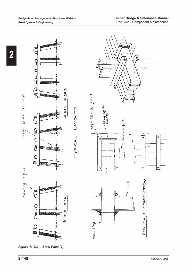
Figure 11.2(b) - Steel Piles (2)
Bridge Asset Management, Structures Division Timber Bridge Maintenance Manual
Road System & Engineering Part Two - Component Maintenance
2-148 February 2005
2

Where piles have lost considerable section area due to corrosion, the axial load and bending
moment in the pile may be excessive, causing the steel to yield and forming a hinge in the
member.
A pile is also deemed to have failed if it moves or settles noticeably under load. This may result
from loss of ground friction support on the pile shaft after scour erosion of the surrounding soil.
Maintenance Activities:
Refer to Part 3 Item 2.31 (56S) for recommended maintenance practices applicable to the various
expected deterioration states for this component.
Refer to Part 4 for a description of applicable maintenance activities.
Further considerations and detailed explanations are as follows:-
Routine Maintenance:
Routine or preventative maintenance actions for steel piles will generally be identified and carried
out during Level 1 bridge inspections. These activities would be:-
• Tightening or replacing of headstock / pile bracket bolts.
• Removal of any aggressive contamination from steel piles.
The headstock attachment bolts should be checked for tightness as this will prevent differential
movement between headstock and piles. Where attachment brackets are welded to the pile and
the brackets are attached directly to the timber headstocks (no steel supplementary headstocks),
packing may be necessary to restore tightness.
Programmed Maintenance:
Driving of steel piles will be carried out as an alternative to using timber piles for existing pile
replacements. The new pile will be driven immediately adjacent to the defective pile.
Advice should be sought from Structures Division to determine expected pile tip levels. This may
require foundation testing if adequate foundation information is not already available, or changed
conditions resulting from scouring has occurred. In addition, pile driving sets to suit the particular
driving equipment to be used on the job must be obtained. Refer to Section 11.1 for information
on expected pile capacity.
Where pile spacings have changed due to new pile installation, the adequacy of the existing
headstock needs to be checked and there may be a requirement for headstock strengthening.
Where replacement piles are driven to stabilise a settling pier the support of the existing piles has
to be disregarded and all loads taken on the new piles. Figure 11.1(b) illustrates these concepts.
New Driven Piles:
Where new piles are to be driven, the general procedures would be:-
• Where existing piles are to be removed, the headstocks are to be tommed to support all
loads.
Bridge Asset Management, Structures Division Timber Bridge Maintenance Manual
Road System & Engineering Part Two - Component Maintenance
February 2005 2-149
2

• Assemble supplementary strengthening members on the headstocks. Contact surfaces shall
be coated with an anti-fungal preservative and grease.
• Cut access for pile driving clearance through the timber headstock. The width of the new
steel pile will be generally greater than the gap between the headstocks. Refer to details in
Figure 11.1(b). Remove the existing pile where required.
Temporary removal of pier bracing and wales will generally be required as well.
For the case of single solid headstocks, the general options are to either remove the member or to
drive new piles on either side to straddle the headstock. Consideration might also be given to
substitution of conventional open headstocks at this stage to ease future headstock replacements.
• Remove surfacing and decking as required to allow placement and driving of the new pile.
The ability of the existing bridge to safely support the construction equipment shall be
considered.
• Install the new pile to follow the line of the defective pile and normally 100mm clear of that
member.
• Trim the pile head as required and install headstock attachment brackets.
• Reinstall bracing and wales including preservatives at pile contact surfaces (if timber
bracing).
• Replace bolts, decking, kerbs and wearing surface where required.
• If new piles are galvanised and the exposed galvanising is damaged, apply a cold -
galvanising product to the affected areas.
Pile Strengthening
Where there is significant loss of section in an existing steel pile due to corrosion, strengthening
will be required. Details of repair work will vary depending on severity of the defect, but will
generally take the form of additional plates welded to the flanges and/or webs of the pile. Defect
details should be submitted to Structures Division for preparation of repair details.
Protection:
It is generally recommended that steel piles be galvanised. However, many piles have been
installed without protective coatings, particularly in the dry areas of the State. Consideration will
need to be given to expected service life and local deterioration rates to determine if protection is
necessary.
Bridge Asset Management, Structures Division Timber Bridge Maintenance Manual
Road System & Engineering Part Two - Component Maintenance
2-150 February 2005
2

11.3 Concrete Piles (56P)
Refer to BIM Appendix D for a description of the four condition states applicable to this
component.
Purpose:
The main function of piles is to transfer vertical loads from span self weight and traffic into the
ground foundation. Other axial loads which may include uplift forces are induced by lateral wind
and flood debris loads. These loads, together with longitudinal traffic braking forces also induce
bending in the pile members. The use of pier bracing and wales helps reduce the amount of
bending incurred in the direction of steam flow.
Significance: Significance Rating 4
Piles may be considered to be primary structural members and form a critical component of the
substructure. Failure of a pile will require all loads it supports to be redistributed through the
headstock to other members. Depending on pile location and headstock strength, the result could
vary from deck surface settlements to partial collapse of the superstructure.
Details:
Concrete piles have been used in a number of timber bridges where the pier has been built of
concrete. The piles were formed of reinforced concrete and were of a square cross section. Figure
11.3 shows typical details.
Failure Mechanism:
Concrete piles in timber bridges are not generally braced and so must withstand axial load from
column action as well as bending from such effects as flood debris and lateral wind or earth
pressure behind abutments.
Failure of a concrete pile is generally the result of loss of section due to spalling of concrete.
Typical causes of this spalling are corrosion induced bursting, salt penetration or fire damage. If
section area is reduced excessively, the concrete will fail in compression (crushing of concrete).
Loss of reinforcing steel due to corrosion will also severely reduce the bending capacity of piles,
causing fracture.
A pile is also deemed to have failed if it moves or settles noticeably under load. This may result
from loss of ground friction support on the pile shaft after scour erosion of the surrounding soil.
Maintenance Activity Numbers Units
56P1 Place concrete encasement M
Bridge Inspection Manual Component No. 56P
Bridge Asset Management, Structures Division Timber Bridge Maintenance Manual
Road System & Engineering Part Two - Component Maintenance
February 2005 2-151
2

Maintenance Activities:
Refer to Part 3 Item 2.32 (56C) for recommended maintenance practices applicable to the various
expected deterioration states for this component.
Refer to Part 4 for a description of applicable maintenance activities.
Figure 11.3 - Concrete Piles
Bridge Asset Management, Structures Division Timber Bridge Maintenance Manual
Road System & Engineering Part Two - Component Maintenance
2-152 February 2005
2

11.4 Wing Piles
Refer to BIM Appendix D for a description of the four condition states applicable to this
component.
For any possible steel or concrete wing pile, use item 60T2 for stabilisation and items from 56S
or 56C for other activities.
Purpose:
The function of wing piles is to support backing slabs and earth pressures from retained
embankment fill.
Significance: Significance Rating 3
Failure of a wing pile will not affect the load carrying ability of abutment Structural files, but
would lead to potential wing collapse and embankment instability or failure.
Failure Mechanism:
Wing piles are under high earth pressure loads and would face either in bending at or below
ground level, or by rotation outboards due to lack of ground support (possibly a result of flood
scouring).
Routine Maintenance:
Routine or preservative maintenance actions for wing piles will generally be as required for main
piles (56T, 56S & 56C). For timber piles, it is recommended that preservative treatment and tin
caps be applied to the tops as they are permanently exposed.
Programmed Maintenance:
Repair and replacement maintenance options for wing piles will generally be as required for main
piles (56T, 56S & 56C).
Where wing piles are notching and leaning forward excessively (nominally more than 40 - 50
mm). Advice should be sought from Structures Division on stabilising procedures. Figure 16.1
shows a possible method consisting of a deadman and ties to prevent further movement.
Maintenance Activities:
Refer to Part 3 Item 2.33 (60T) for recommended maintenance practices applicable to the various
expected deterioration states for this component.
Refer to Part 4 for a description of applicable maintenance activities.
Maintenance Activity Numbers Units
60T1 Replace timber wing pile Each
60T2 Stabilise wing pile Lump sum
Bridge Inspection Manual Component No. 60T, 60S, 60C
Bridge Asset Management, Structures Division Timber Bridge Maintenance Manual
Road System & Engineering Part Two - Component Maintenance
February 2005 2-153
2

12.0 Bracing & Wales
12.1 Timber Bracing (57T)
Refer to BIM Appendix D for a description of the four condition states applicable to this
component.
Purpose:
The main function of bracing and wales is to help transfer lateral structure forces from wind and
flood debris to the foundation. They act to reduce bending effects in the bridge piles.
Significance: Significance Rating 3
Diagonal bracings is used in piers where pile height exceeds a specific amount and is important
for reducing pile bending effects. If missing or defective, failure of the piles under debris loading
is possible.
Details:
Diagonal bracing and wales consist of members on both sides of piers, with details generally as
shown in Figure 12.1. Bracing is attached to all timber piled piers exceeding 1.5m in height.
Failure Mechanism:
The effectiveness of bracing will be lost if bolted connections become loose due to timber rotting
or if the actual members have lost significant area due to rotting or termite attack. The member
has failed if it is unable to transfer longitudinal load due to the above defects.
Materials:
Refer to Main Roads Specification MRS 11.87 for acceptable timber species and properties for
timber bracing.
Maintenance Activities:
Refer to Part 3 Item 2.34 (57T) for recommended maintenance practices applicable to the various
expected deterioration states for this component.
Refer to Part 4 for a description of applicable maintenance activities.
Maintenance Activity Numbers Units
57T1 Replace braces / wales M
57T2 Add new braces / wales M
57T3 Remove and replace braces / wales Lump sum
57T4 Splice wale Lump sum
Bridge Inspection Manual Component No. 57T
Bridge Asset Management, Structures Division Timber Bridge Maintenance Manual
Road System & Engineering Part Two - Component Maintenance
2-154 February 2005
2

Figure 12.1 - Timber Bracing & Wales
Bridge Asset Management, Structures Division Timber Bridge Maintenance Manual
Road System & Engineering Part Two - Component Maintenance
February 2005 2-155
2

12.2 Steel Bracing (57S)
Refer to BIM Appendix D for description of the four condition states applicable to this
component.
Purpose:
The main function of bracing and wales is to help transfer lateral structure forces from wind and
flood debris to the foundations. They act to reduce bending effects in the bridge piles.
Significance: Significance Rating 3
Diagonal bracing is used in piers where pile height exceeds a specified amount and is important
for reducing pile bending effects. If missing or defective, failure of the piles under flood debris
loading is possible.
Details:
Steel bracing and wales were not originally used in timber bridges and where found as a result of
maintenance replacement of the original timber members. Members are generally of a channel
section and may be unpainted or galvanised. Figure 12.2 shows typical details.
Failure Mechanism:
The effectiveness and function of bracing members will be lost if bolted connections become
loose due to rot in timber piles or there is a significant loss of section due to steel corrosion,
causing the member to buckle or fail in bearing or compression.
Maintenance Activities:
Refer to Part 3 Item 2.35 (57S) for recommended maintenance practices applicable to the various
expected deterioration states for this component.
Refer to Part 4 for a description of applicable maintenance activities.
Maintenance Activity Numbers Units
57S1 Replace steel braces / wales M
57S2 Add new steel braces / wales M
Bridge Inspection Manual Component No. 57S
Bridge Asset Management, Structures Division Timber Bridge Maintenance Manual
Road System & Engineering Part Two - Component Maintenance
2-156 February 2005
2
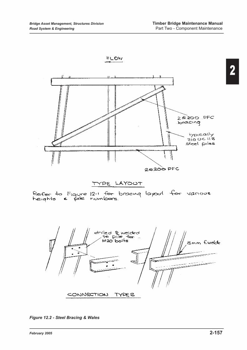
Figure 12.2 - Steel Bracing & Wales
Bridge Asset Management, Structures Division Timber Bridge Maintenance Manual
Road System & Engineering Part Two - Component Maintenance
February 2005 2-157
2

13.0 Sill Log or Footing
13.1 Timber Sill (59T)
Refer to BIM Appendix for a description of the four condition states applicable to this component.
Purpose:
The function of a timber sill log is to support shortened piles at a pier or abutment and transfer
loads into the foundations. They are used where is not possible to drive piles because of rock or
excessively firm foundation material.
Significance: Significance Rating 3
Failure of a timber sill log will normally be caused by rotting, allowing settlement of the overlying
piles and deck.
Details:
Figure 13.1 shows details of timber sill members. The piles were keyed to the sill beam by a
spigot and socket detail. Attachment bolts were placed and were particularly important on the
upstream piles to resist any up forces resulting from flood loading.
Failure Mechanism:
Sill logs will most likely fail as a result of rotting, allowing the pile above to drop through the
member as it loses integrity.
Materials:
Refer to Main Roads Specification MRS 11.87 for acceptable timber species and properties for
timber sills.
Maintenance Activities:
Refer to Part 3 Item 2.36 (59T) for recommended maintenance practices applicable to the various
expected deterioration states for this component.
Refer to Part 4 for a description of applicable maintenance activities.
Maintenance Activity Numbers Units
59T1 Replace sill in timber M
59T2 Partially replace sill in timber M
59T3 Replace pile connections Each
Bridge Inspection Manual Component No. 59T
Bridge Asset Management, Structures Division Timber Bridge Maintenance Manual
Road System & Engineering Part Two - Component Maintenance
2-158 February 2005
2

Figure 13.1 - Timber Sill
Bridge Asset Management, Structures Division Timber Bridge Maintenance Manual
Road System & Engineering Part Two - Component Maintenance
February 2005 2-159
2

13.2 Concrete Sill (59C)
Refer to BIM Appendix D for a description of the four condition states applicable to this
component.
Purpose:
The function of a concrete sill is to support shortened piles at a pier and transfer all pier loads into
the foundations. They were used where rock material close to the surface precluded the driving
of piles.
Significance: Significance Rating 3
Failure of concrete sill could result from excessive spalling below pile contact areas, allowing the
pile to settle.
Details:
Figure 13.2 shows details of concrete sills.
Failure Mechanism:
Spalling of concrete below piles due to bursting from corroding reinforcement or debris impacts
could reduce the sill's ability to support the overlying pile, allowing it to settle.
Maintenance Activities:
Refer to Part 3 Item 2.37 (59C) for recommended maintenance practices applicable to the various
expected deterioration states for this component.
Refer to Part 4 for a description of applicable maintenance activities.
Maintenance Activity Numbers Units
59C1 Replace sill in concrete M3
59C2 Partially replace sill in concrete M3
59C3 Replace pile connections Each
Bridge Inspection Manual Component No. 59C
Bridge Asset Management, Structures Division Timber Bridge Maintenance Manual
Road System & Engineering Part Two - Component Maintenance
2-160 February 2005
2

Figure 13.2 - Concrete Sill
Bridge Asset Management, Structures Division Timber Bridge Maintenance Manual
Road System & Engineering Part Two - Component Maintenance
February 2005 2-161
2

14.0 Abutment
14.1 Concrete Abutment (50C)
Refer to BIM Appendix D for a description of the four condition states applicable to this
component.
Purpose:
The main function of an abutment is to transfer vertical and longitudinal loads on bridge and spans
to the foundations. The abutment must also withstand earth pressure loads from the adjacent
compacted embankment fill.
Significance: Significance Rating 3
Depending on the mechanism, the consequences of abutment failure will vary from noticeable
settlements at deck level to partial collapse of the end span.
Details:
Where rock or firm material occurred close to the surface, a common form of abutment in timber
bridges was the concrete gravity type wall as shown in Figure 14.1. Though essentially mass
concrete, there is generally some reinforcing in the bearing shelf area. Handhold recesses for the
girder hold down bolts were often incorporated.
Another form of concrete abutment consisted of a conventional RC headstock supported on square
RC driven piles or columns.
A cantilever type RC retaining wall was occasionally used for timber bridge jobs - Figure 14.1.
Failure Mechanism:
The method of failure of concrete abutments depends on the abutment type. For gravity retaining
wall types the most common failure type observed has been settlement with possible rotation as a
result of flood or stream flow scouring of the material below the footing. This leads to large
settlement of the span end.
Another type of failure can be the loss of girder support due to significant spalling out of the
support area.
For concrete headstocks on piles or column, there is the potential for bending and shear failure,
as well as spalling as a result of reinforcement corrosion.
Maintenance Activity Numbers Units
50C1 Reconstruct ballast wall M
Bridge Inspection Manual Component No. 50C
Bridge Asset Management, Structures Division Timber Bridge Maintenance Manual
Road System & Engineering Part Two - Component Maintenance
2-162 February 2005
2

Figure 14.1 - Concrete Abutment
Bridge Asset Management, Structures Division Timber Bridge Maintenance Manual
Road System & Engineering Part Two - Component Maintenance
February 2005 2-163
2

Maintenance Activities:
Refer to Part 3 Item 2.38 (50C) for recommended maintenance practices applicable to the various
expected deterioration states for this component.
Refer to Part 4 for a description of applicable maintenance activities.
Additional:
Substitution of a concrete abutment to replace existing timber headstocks may be achieved if the
timber piles are in acceptable condition. Figure 14.1(2) shows the general concept. Contact
Structures Division for proposal details if this concept is being considered.
Figure 14.1(3) shows a detail using a concrete sill to try and improve the durability of a timber
abutment. The sill would be designed as a small retaining wall and separates the timber bridge
components from the approaches by introducing an open deck joint. This provides both reduced
moisture access to the bridge and provides a barrier to insect attack.
14.2 Masonry Abutment (50O)
Refer to BIM Appendix D for a description of the four condition states applicable to this
component.
Purpose:
The main function of an abutment is to transfer vertical and longitudinal loads on the bridge and
span to the foundations. The abutment must also withstand earth pressure loads from the adjacent
compacted embankment fill.
Significance: Significance Rating 3
Depending on the mechanism, the consequences of abutment failure will vary from noticeable
settlements at deck level to partial collapse of the end span.
Details:
Figure 14.2 shows typical details for rubble masonary abutments, which are gravity type retaining
wall structures. A lightly reinforced cap was placed on top of the wall to provide a tie across the
abutment and an even girder support area. This type of abutment was used where rock or firm
material precluded the driving of piles.
Maintenance Activity Numbers Units
50O1 Repair mortar M2
Bridge Inspection Manual Component No. 50O
Bridge Asset Management, Structures Division Timber Bridge Maintenance Manual
Road System & Engineering Part Two - Component Maintenance
2-164 February 2005
2

Failure Mechanism:
The most common form of failure would be settlement and possible overturning rotations as a
result of flood or streamflow scour of the supporting material. As well, there is the potential for
collapse of the structure due to the breaking down of the concrete matrix holding the stones
together.
These defects can lead to deck settlements as partial collapse of the end span.
Maintenance Activities:
Refer to Part 3 Item 2.39 (50O) for recommended maintenance practices applicable to the various
expected deterioration states for this component.
Refer to Part 4 for a description of applicable maintenance activities.
Figure 14.2 - Masonry Abutment
Bridge Asset Management, Structures Division Timber Bridge Maintenance Manual
Road System & Engineering Part Two - Component Maintenance
February 2005 2-165
2

15.0 Abutment Sheeting / Infill
15.1 Timber Planks & Ballast Boards (52T)
Refer to BIM Appendix D for a description of the four condition states applicable to this
component.
Purpose:
The function of backing slabs is to retain the compacted embankment fill behind piled abutments.
They also provide protection against flood and stream flow scour of the supported soil.
Significance: Significance Rating 2
Any failure of backing slabs will allow loss of retained fill material due to scour or soil slippage,
resulting in settlement of the road approach. The resultant bump at the end of the bridge will
cause higher dynamic vehicle loads on the bridge as well as effecting the safe operation of
vehicles.
Details:
Timber backing slabs are not detailed on any timber bridge standard drawings, so it is assumed
that these were substituted for the normal precast concrete slabs during construction or later
maintenance operations.
Ballast boards are used to hold the compacted approach fill over the depth of the girders while
coverboards provide sacrificial protection to the rear headstock member. Refer to Figure 15.1.
Failure Mechanism:
As a result of loss of bending capacity of timber slabs due to rotting or termite attack, earth
pressure behind the slabs my cause collapse, allowing slumping out or scouring of the full
material. As well, scouring at the base of the backing slabs may allow dropping down of the slabs
and exposure of the fill material to further loss.
Maintenance Activities:
Refer to Part 3 Item 2.40 (52T) for recommended maintenance practices applicable to the various
expected deterioration states for this component.
Refer to Part 4 for a description of applicable maintenance activities.
Maintenance Activity Numbers Units
52T1 Replace sheeting planks M2
52T2 Splice sheeting planks M2
52T3 Reposition sheeting M2
Bridge Inspection Manual Component No. 52T
Bridge Asset Management, Structures Division Timber Bridge Maintenance Manual
Road System & Engineering Part Two - Component Maintenance
2-166 February 2005
2

Figure 15.1 - Timber Backing Boards
Bridge Asset Management, Structures Division Timber Bridge Maintenance Manual
Road System & Engineering Part Two - Component Maintenance
February 2005 2-167
2

Because of the high cost of fill excavation to replace backing boards, splicing in of sections as
shown in Figure 15.1(2) may be considered.
Badly bulged existing planks may need to be removed to allow new sheeting to be placed hard
against the existing boards. Provided the fill is dry, single boards may be removed one at a time
without effecting fill stability. The new planks are placed in front of the existing planks and
locked in place with retaining planks bolted through the piles.
Any voids behind the planks can be filled with a slurry mortar poured in from above.
15.2 Concrete Planks (52P)
Refer to BIM Appendix D for a description of the four condition states applicable to this
component.
Purpose:
The function of backing slabs is to retain the compacted embankment fill behind piled abutments.
They also provide protection against flood and streamflow scour of the supported soil.
Significance: Significance Rating 2
Any failure of backing slabs will allow loss of retained fill material due to scour or soil slippage,
resulting in settlement of the road approach. The resulting bump at the end of the bridge will
cause higher dynamic vehicle loads on the bridge as well as effecting the safe operation of
vehicles.
Details:
Concrete backing slabs are the specified type of backing slabs on timber bridge drawings. They
are reinforced slabs, conventionally cast on site and placed behind driven piles. Details of these
slabs are shown in Figure 15.2.
Failure Mechanism:
Loss of section caused by spalling of concrete resulting from reinforcement corrosion may cause
slabs to fail in bending.
As well, scouring at the base of the backing slabs may allow dropping down of the slabs and
exposure of the fill material to erosion loss.
Maintenance Activity Numbers Units
52P1 Replace concrete planks M2
52P2 Reposition concrete planks M2
Bridge Inspection Manual Component No. 52P
Bridge Asset Management, Structures Division Timber Bridge Maintenance Manual
Road System & Engineering Part Two - Component Maintenance
2-168 February 2005
2

Maintenance Activities:
Refer to Part 3 Item 2.41 (52P) for recommended maintenance practices applicable to the various
expected deterioration states for this component.
Refer to Part 4 for description of applicable maintenance activities.
Figure 15.2 - Concrete Backing Slabs
Bridge Asset Management, Structures Division Timber Bridge Maintenance Manual
Road System & Engineering Part Two - Component Maintenance
February 2005 2-169
2

15.3 Concrete Infill (52C)
Refer to BIM Appendix D for a description of the four condition states applicable to this
component.
Purpose:
The purpose of concrete infill walls is to help retain the embankment fill behind piled abutments
and to prevent erosion of this material due to streamflow.
Significance: Significance Rating 2
Any failure of the wall will allow erosion or slumping out of the fill materials, leading to a cavity
behind the abutment with associated settlement of the road surface. Such depressions lead to an
increase in dynamic vehicle loads on the bridge.
Details:
These infills walls were cast in-situ as gravity sections and were of mass concrete construction.
Ideally there was a separation material against the piles to allow independent movement of the
wall and so prevent the transfer of earth pressure loads to the piles.
Figure 15.3 shows typical details.
Failure Mechanism:
Settlement and / or rotation leading to gaps between headstocks and walls is generally caused by
inadequate founding materials, resulting in softening when wet, with or without scour action.
Proper consideration of soil capacity and hydraulic action needs to be given.
If stream flow undermines this type of block wall, it is possible for the wall to tilt out and in
extreme cases it is possible for the wall to overturn. Such walls are subject to both static earth
pressure loads and surcharge earth loads produced by vehicles.
Maintenance Activities:
Refer to Part 3 Item 2.42 (52C) for recommended maintenance practices applicable to the various
expected deterioration states for this component.
Refer to Part 4 for a description of applicable maintenance activities.
Maintenance Activity Numbers Units
52C1 Seal gaps - concrete Lump sum
52C2 Stabilise wall Lump sum
Bridge Inspection Manual Component No. 52C
Bridge Asset Management, Structures Division Timber Bridge Maintenance Manual
Road System & Engineering Part Two - Component Maintenance
2-170 February 2005
2

Figure 15.3 - Concrete / Masonry infill walls
15.4 Rock Fill (52O)
Refer to BIM Appendix D for a description of the four condition states applicable to this
component.
Purpose:
Rock fill was used in lieu of conventional abutment sheeting to provide scour protection to the
compacted embankment fill behind piled abutments. The rock fill also performed the normal
function of wing walls.
Details:
Figure 15.4 shows typical details for this component. This protection was formed by dumping
rock to spill through between the abutment piles. Often the surface was hand packed and grouted
to provide extra protection against scour.
Maintenance Activity Numbers Units
52O1 Place additional rock fill M3
5202 Patch grouted surface Lump sum
Bridge Inspection Manual Component No. 52O
Bridge Asset Management, Structures Division Timber Bridge Maintenance Manual
Road System & Engineering Part Two - Component Maintenance
February 2005 2-171
2

Significance: Significance Rating 2
Loss of the rock protection will lead to erosion of the embankment fill. Loss of material behind
the abutment will result in road surface depression with consequent increase in dynamic traffic
loads on the bridge.
Failure Mechanism:
The most common failure is settling of the rock spill as a result of undermining by flood scour.
Cracking of the surface when grouted can also lead to loss of fill material due to erosion.
Maintenance Activities:
Refer to Part 3 Item 2.43 (52O-Rockfill) for recommended maintenance practices applicable to
the various expected deterioration states for this component.
Refer to Part 4 for a description of applicable maintenance activities.
Figure 15.4 - Rock Fill Protection
Bridge Asset Management, Structures Division Timber Bridge Maintenance Manual
Road System & Engineering Part Two - Component Maintenance
2-172 February 2005
2

15.5 Masonry Infill (52O)
Refer to BIM Appendix D for a description of the four condition states applicable to this
component.
Purpose:
As for concrete infill (Section 15.3)
Significance: Significance Rating 2
As for concrete infill (Section 15.3)
Details:
This type of construction was an alternative to mass concrete and generally took the same form
and dimensions - Figure 15.3.
Failure Mechanism:
As for concrete infill (Section 15.3)
Maintenance Activities:
Refer to Part 3 Item 2.44 (52O - masonry) for recommended maintenance practices applicable to
the various expected deterioration states for this component.
Refer to Part 4 for a description of applicable maintenance activities.
Maintenance Activity Numbers Units
Refer to Activities for Masonry Abutment
Bridge Inspection Manual Component No. 520
Bridge Asset Management, Structures Division Timber Bridge Maintenance Manual
Road System & Engineering Part Two - Component Maintenance
February 2005 2-173
2

15.6 Timber Sill Abutment (52T)
Refer to BIM Appendix D for a description of the four condition states applicable to this
component.
Purpose:
The main function of an abutment is to transfer vertical and longitudinal loads on bridge end spans
to the foundations. The abutment must also withstand earth pressure loads from the adjacent
compacted embankment fill.
Significance: Significance Rating 3
Depending on the mechanism, the consequences of abutment failure will vary from noticeable
settlements at deck level to partial collapse of the end span.
Details:
This type of abutment consisted essentially of logs one above the other to form a wall and were
generally seated on a concrete footing as shown in Figure 15.6. Abutments of this type were
generally low, with vertical bolts used to hold the assembly together.
Failure Mechanism:
The expected mode of failure would be vertical settlement due to rotting of the logs and as a result
of earth pressure loads, possible collapse.
Maintenance Activities:
Refer to Part 3 Item 2.45 (52T - Sill abutment) for recommended maintenance practices applicable
to the various expected deterioration states for this component.
Refer to Part 4 for a description of applicable maintenance activities.
Maintenance Activity Numbers Units
52T4 Replace abutment log Each
Bridge Inspection Manual Component No. 52T
Bridge Asset Management, Structures Division Timber Bridge Maintenance Manual
Road System & Engineering Part Two - Component Maintenance
2-174 February 2005
2

Figure 15.6 - Timber Sill Abutment
Bridge Asset Management, Structures Division Timber Bridge Maintenance Manual
Road System & Engineering Part Two - Component Maintenance
February 2005 2-175
2

16.0 Wing Walls
16.1 Timber Plank Sheeting (51T)
Refer to BIM Appendix D for a description of the four condition states applicable to this
component.
Purpose:
The function of a wing is to provide protection to and terminate the road embankment at the sides
of bridge abutments.
Significance: Significance Rating 3
Wings are important because they help prevent scour of embankment fill as a result of steam flow
or flood. Without such protection, it is possible for scouring to progress to a washout behind the
abutment.
Details:
This type of wing consisted of timber backing slabs, spanning across driven wing piles, as shown
Figure 16.1.
Failure Mode:
The most common failure mode is bending failure in the timber planks as a result of loss of section
due to rotting. Similarly, failure of rotted piles may occur if they are unable to withstand the
embankment earth pressure loads.
As well, scouring at the base of the wing may allow dropping down of the slabs and exposure of
the fill material to erosion loss.
Maintenance Activities:
Refer to Part 3 Item 2.46 (51T) for recommended maintenance practices applicable to the various
expected deterioration states for this component.
Refer to Part 4 for a description of applicable maintenance activities.
Maintenance Activity Numbers Units
Refer to Activities for Abutment Sheeting Timber Planks
Bridge Inspection Manual Component No. 51T
Bridge Asset Management, Structures Division Timber Bridge Maintenance Manual
Road System & Engineering Part Two - Component Maintenance
2-176 February 2005
2

Figure 16.1 - Plank Wings
Bridge Asset Management, Structures Division Timber Bridge Maintenance Manual
Road System & Engineering Part Two - Component Maintenance
February 2005 2-177
2

16.2 Concrete Plank Sheeting (51P)
Refer to BIM Appendix D for a description of the four condition states applicable to this
component.
Purpose:
The function of a wing is to provide protection to and terminate the road embankment at the sides
of bridge abutments.
Significance: Significance Rating 3
Wings are important because they help prevent scour of embankment fill as a result of stream flow
or flood. Without such protection, it is possible for scouring to progress to a washout behind the
abutment.
Details:
This type of wing consisted of precast concrete backing slabs spanning across driven wing piles,
as shown in Figure 16.1.
Failure Mode:
Loss of section caused by spalling of concrete as a result of reinforcement corrosion may cause
slabs to fail in bending.
As well, scouring at the base of the wing may allow dropping down of the slabs and exposure of
the fill material to erosion loss.
Maintenance Activities:
Refer to Part 3 Item 2.47 (51P) for recommended maintenance practices applicable to the various
expected deterioration states for this component.
Refer to Part 4 for a description of applicable maintenance activities.
Maintenance Activity Numbers Units
Refer to Activities for Abutment Sheeting - Concrete Planks Concrete Planks
Bridge Inspection Manual Component No. 51P
Bridge Asset Management, Structures Division Timber Bridge Maintenance Manual
Road System & Engineering Part Two - Component Maintenance
2-178 February 2005
2

16.3 Concrete Wing (51C)
Refer to BIM Appendix D for a description of the four condition states applicable to this
component.
Purpose:
The function of a wing is to provide protection to and terminate the road embankment at the sides
of bridge abutments.
Significance: Significance Rating 3
Wings are important because they help prevent scour of embankment fill as a result of stream flow
or flood. Without such protection, it is possible for scouring to progress to a washout behind the
abutment.
Details:
These wings were cast in-situ as gravity sections and were of mass concrete construction. Figure
16.3 shows typical details.
Failure Mode:
If streamflow undermines this type of block wall, it is possible for the wall to tilt out under the
action of earth pressure, with overturning an extreme possibility.
Maintenance Activities:
Refer to Part 3 Item 2.48 (51C) for recommended maintenance practices applicable to the various
expected deterioration states for the component.
Refer to Part 4 for a description of applicable maintenance activities.
Maintenance Activity Numbers Units
Refer to activities for concrete repair
Bridge Inspection Manual Component No. 51C
Bridge Asset Management, Structures Division Timber Bridge Maintenance Manual
Road System & Engineering Part Two - Component Maintenance
February 2005 2-179
2

Figure 16.3 - Concrete / Masonry Wing
16.4 Masonry Wing (51O)
Refer to BIM Appendix D for a description of the four condition states applicable to this
component.
Purpose:
As for concrete Wings (16.3).
Significance: Significance Rating 3
As for concrete wings (16.3).
Details:
This type of construction was an alternative to mass concrete and generally took the same form
and dimensions - Figure 16.3
Failure Mechanism:
As for concrete wings (16.3).
Maintenance Activity Numbers Units
Refer activities for Masonry repair
Bridge Inspection Manual Component No. 51O
Bridge Asset Management, Structures Division Timber Bridge Maintenance Manual
Road System & Engineering Part Two - Component Maintenance
2-180 February 2005
2

Maintenance Activities:
Refer to Part 3 Item 2.49 (51O) for recommended maintenance practices applicable to the various
expected deterioration states for this component.
Refer to Part 4 for a description of applicable maintenance activities.
17.0 Miscellaneous
17.1 Bolts
Details:
Bolt sizes and spacings shall be as shown in Figures 17.1(a) - (d).
All new bolts supplied shall be galvanised. Wherever possible, existing bolts should be re-used,
after application of protective coating as required.
All bolts should be coated with grease before insertion in bolt holes in order to provide further
protection to timber components.
Bolts may require packing with steel washers and tightened to refusal. Care must be exercised to
prevent over tightening, causing crushing below washers.
Refer to Part 4 for a description of applicable maintenance activities.
Maintenance Activity Numbers Units
120S1 Tighten existing bolts Lump sum
120S2 Replace or install bolts Each
120S3 Replace anchor bolts Each
120S4 Install large size washers Each
120S8 Supply new bolts kg
Bridge Asset Management, Structures Division Timber Bridge Maintenance Manual
Road System & Engineering Part Two - Component Maintenance
February 2005 2-181
2

Figure 17.1(a) - Bolts (1)
Bridge Asset Management, Structures Division Timber Bridge Maintenance Manual
Road System & Engineering Part Two - Component Maintenance
2-182 February 2005
2

Figure 17.1(b) - Bolts (2)
Bridge Asset Management, Structures Division Timber Bridge Maintenance Manual
Road System & Engineering Part Two - Component Maintenance
February 2005 2-183
2

Figure 17.1(c) - Bolts (3)
Bridge Asset Management, Structures Division Timber Bridge Maintenance Manual
Road System & Engineering Part Two - Component Maintenance
2-184 February 2005
2

Figure 17.1(d) - Bolts (4)
Bridge Asset Management, Structures Division Timber Bridge Maintenance Manual
Road System & Engineering Part Two - Component Maintenance
February 2005 2-185
2

17.2 Running Planks
Purpose:
Hardwood timber running planks were used, generally in conjunction with distributor planks to
improve decking performance. They provided enhanced distribution of wheel loads to deck
planks and would span individual deteriorated planks.
General:
Placement of new running planks is not generally recommended today because of the increased
potential for rotting of adjacent decking due to moisture trapped between these members. In
addition, ends of running planks are prone to deterioration around spikes resulting in looseness.
Consideration may be given to removal of these members and replacement with AC. In general,
distributors could be retained, but would probably require a new set of attachment bolts.
Refer to Part 4 for a description of applicable/maintenance activities
Figure 17.2 - Running Planks
Maintenance Activity Numbers Units
29T3 Replace & retighten running planks M
Bridge Asset Management, Structures Division Timber Bridge Maintenance Manual
Road System & Engineering Part Two - Component Maintenance
2-186 February 2005
2

17.3 Distributors
Purpose:
Timber or steel distributors are used to improve distribution of wheel loads to decking. Hardwood
distributors were generally placed under hardwood decks (often in conjunction with running
planks) as a maintenance addition to also improve general tightness of the deck. Alternatively,
steel members would be suitable. The general use of distributors is beneficial to the deck system
and is recommended.
Distributors are also considered essential under ply decks to reduce differential deflection of the
sheet edges under traffic wheels and so reduce break up of the AC wearing surface. Steel
distributors are generally detailed for this purpose though some use of hardwood was initially
made.
Steel angle distributors are an essential part of PSC decking in order to spread wheel loads
between planks.
Details:
Figure 17.3(a) shows the traditional use of hardwood distributors under hardwood decks, with
fastener spacings as typically used. For steel distributors similar spacings are appropriate.
Supply of hardwood distributors shall be to the requirements of MRS 11.87.
Figure 5.2(b) shows details suitable for ply decks.
Distributors shall be lapped as required by the drawings.
Refer to Part 4 for a description of Maintenance Activities applicable.
Maintenance Activity Numbers Units
120T1 Install distributor planks (HW) M
120T2 Replace & retighten distributor planks (HW) M
130S3 Install distributors (steel) M
130S4 Replace distributors (steel M
Bridge Asset Management, Structures Division Timber Bridge Maintenance Manual
Road System & Engineering Part Two - Component Maintenance
February 2005 2-187
2

Figure 17.3 - Distributors - HW Decks
17.4 3mm Deck Plate
Purpose:
Thin galvanised steel plate has been laid over deteriorated timber decks in order to extend their
life. The plate is 3mm thick and is screwed to the decking with a close grid of screws. The plate
helps wheel loads span across gaps or weak deck planks.
Details:
Figure 17.4 shows the general details which have been used. Reference 12 gives details of testing
and evaluation of this system on a timber bridge.
Maintenance Activity Numbers Units
100M7 Lay 3mm galvanised steel plate decking M2
Bridge Asset Management, Structures Division Timber Bridge Maintenance Manual
Road System & Engineering Part Two - Component Maintenance
2-188 February 2005
2

Coach bolts or screws shall be used to attach the steel plate securely to the timber decking. In
order to effectively transfer wheel loads, no more than three isolated defective deck planks or two
adjacent defective planks are allowed in any metre length of sheeted decking. If this cannot be
achieved, some replacement of deck planks will be necessary.
Note that the use of this system is not actually compatible with general strategies for maintenance
as given in 2.1.1 Part 1 because of the retention of deterioration components. The top of
deteriorated decking is covered by the steel plate so the decking condition can only be determined
from below and the ends. Some Districts claim success with this system as it allows an extended
life for decking, but material costs will be high.
Refer to Part 4 for a description of maintenance activities applicable.
Refer to Appendix D(16) for a Supplementary Specification which may be used for the placement
of 3mm deck plate.
Reference
12. Infratech Systems and Services. (1998). Performance of a Deteriorated and Rehabilitated
Timber Bridge Deck.
Figure 17.4 - 3mm Plate
Bridge Asset Management, Structures Division Timber Bridge Maintenance Manual
Road System & Engineering Part Two - Component Maintenance
February 2005 2-189
2
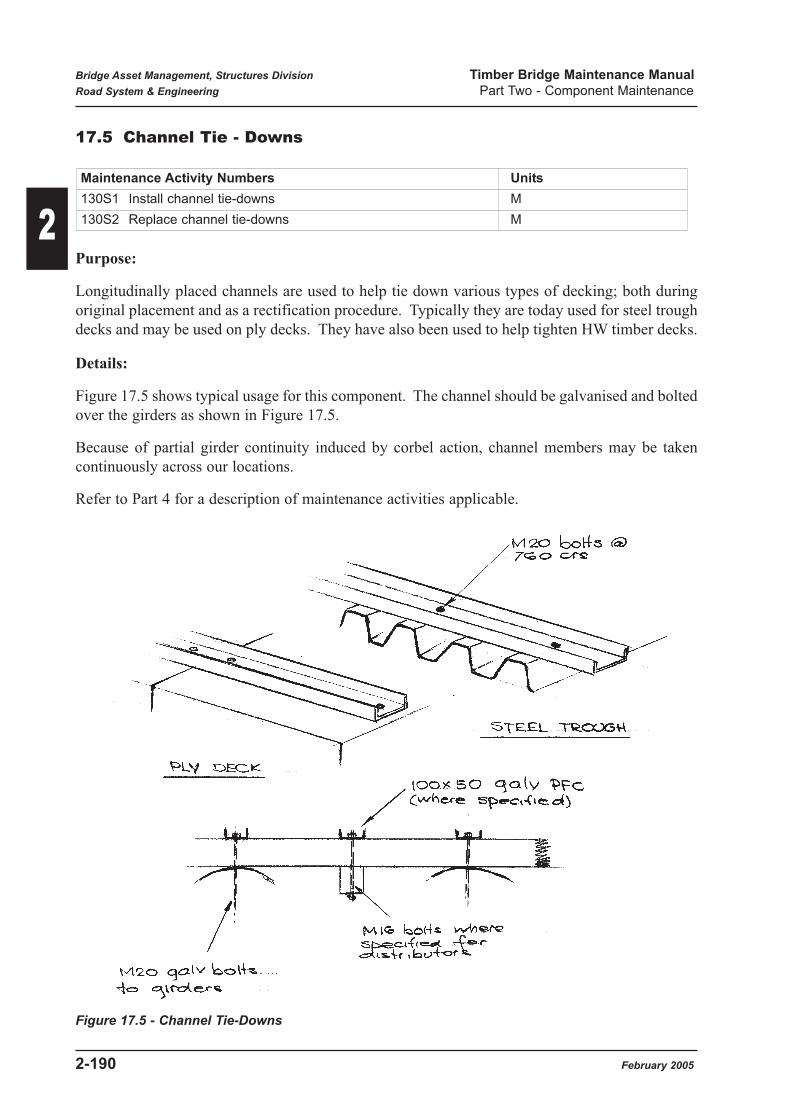
17.5 Channel Tie - Downs
Purpose:
Longitudinally placed channels are used to help tie down various types of decking; both during
original placement and as a rectification procedure. Typically they are today used for steel trough
decks and may be used on ply decks. They have also been used to help tighten HW timber decks.
Details:
Figure 17.5 shows typical usage for this component. The channel should be galvanised and bolted
over the girders as shown in Figure 17.5.
Because of partial girder continuity induced by corbel action, channel members may be taken
continuously across our locations.
Refer to Part 4 for a description of maintenance activities applicable.
Figure 17.5 - Channel Tie-Downs
Maintenance Activity Numbers Units
130S1 Install channel tie-downs M
130S2 Replace channel tie-downs M
Bridge Asset Management, Structures Division Timber Bridge Maintenance Manual
Road System & Engineering Part Two - Component Maintenance
2-190 February 2005
2

17.6 Tingling
Purpose:
Tingling is the placement of cover strips (metal generally) over excessive gaps between hardwood
deck planks prior to the application of bituminous wearing surface. This is to prevent the
dropping of the DWS through the gaps.
Details:
Figure 17.6 shows the general concept.
The tingling should be securely fixed to the decking with coach bolts, screws or clouts so as not
to vibrate loose.
Refer to Part 4 for a description of maintenance activities applicable.
Figure 17.6 - Tingling
Maintenance Activity Numbers Units
100M8 Lay Tingling M
Bridge Asset Management, Structures Division Timber Bridge Maintenance Manual
Road System & Engineering Part Two - Component Maintenance
February 2005 2-191
2

17.7 Preservative Treatments
Purpose:
Preservative treatments are applied to timber components in order to slow down the process of
degradation from both biological attack and weathering.
General:
Timber rotting is caused by fungii living in or on the component and consuming part of the
structure of the timber. This type of deterioration is generally controlled by the application of
surface treatments which may be sprayed or painted on. Figure 17.7 shows lists and applications
of generally used and proven chemical preservatives.
Baron rods which are placed in drilled holes are also included as a chemical preservative - refer
Figure 7.1(b) Part 1.
Envelope treatment of sawn timber girders may also be considered as a means of extending girder
life - refer Section 8.1.
Because rot fungii require water or a high moisture content to survive, a strategy to limit water
collection is beneficial. The use of grease and a layer of bitumen impregnated compressible
material at contact surfaces between timber components is recommended in order to reduce the
potential for water pockets to be trapped between surfaces. Figure 17.7 lists recommended
materials for this process.
Refer to Part 4 for a description of applicable maintenance activities.
Maintenance Activity Numbers Units
100T1 Apply chemical preservative to timber Lump sum
100T2 Apply preservative grease to timber Lump sum
100T5 Apply end sealant Lump sum
100T7 Place bituminous felt Lump sum
Bridge Asset Management, Structures Division Timber Bridge Maintenance Manual
Road System & Engineering Part Two - Component Maintenance
2-192 February 2005
2

Figure 17.7 (a) - Preservatives & Sealants (1)
Bridge Asset Management, Structures Division Timber Bridge Maintenance Manual
Road System & Engineering Part Two - Component Maintenance
February 2005 2-193
2

Figure 17.7 (b) - Preservatives & Sealants (2)
Bridge Asset Management, Structures Division Timber Bridge Maintenance Manual
Road System & Engineering Part Two - Component Maintenance
2-194 February 2005
2

17.8 Termite Poisoning
Purpose:
Anti-termite poisoning is carried out on
(a) New girders, corbels and piles as a guard against attack.
(b) Infested members in order to kill the termites and stop further damage.
General:
Poisoning is an on-going procedure at recommended intervals of 4 years. However, once termite
presence is detected, treatment should be carried out as soon as practical in order to limit damage.
A list of approved termicides is given in Table 7.2(a) (Part 1). Where another chemical is
proposed, details including NRS registration proof shall be submitted to BAM for approval.
Poisoning will be carried out by drilling holes into the heart of the member, injecting the liquid
poison and plugging the hole with a removable plug. Figure 17.8 shows the required locations for
poison applications and a list of approved proprietary products.
For future reference, the date, month and year that the structure was poisoned should be clearly
marked at the abutment 1 headstock.
Some improvement in effectiveness is expected if chemical use is rotated.
Covered termite trails may be treated with arsenic trioxide dust applied by a hand puffer as noted
in Section 7.2(Part 1).
Refer to Part 4 for a description of applicable maintenance activities.
Refer to Appendix D(19) for a Supplementary Specification which may be used for the poisoning
of termites.
Maintenance Activity Numbers Units
110T1 Drill & inject termicide poison into timber Lump sum
110T2 Poison termite nest or trails Lump sum
Bridge Asset Management, Structures Division Timber Bridge Maintenance Manual
Road System & Engineering Part Two - Component Maintenance
February 2005 2-195
2

Figure 17.8 - Termite Poisoning
Bridge Asset Management, Structures Division Timber Bridge Maintenance Manual
Road System & Engineering Part Two - Component Maintenance
2-196 February 2005
2

17.9 Deck Recambering
Purpose:
Because hardwood decking is not physically connected to internal girders, tightness of the
decking is developed by jacking up the internal girders with respect to the outer girders. The
process is called "cambering" and the resultant reduction in differential movement between girder
and decking helps reduce wear and rattling.
Details:
Standard DMR timber bridge drawings specify girders to be placed such that a small amount of
upward curvature equivalent to a 16mm camber occurs in timber decking. Because of creep in
timber under strain, the effectiveness of this procedure reduces with time. From time to time, a
recambering of girders is required to re-establish deck tightness.
From earlier analysis carried out, it is recommended that a jacking of a centre girder be limited to
25mm at re-cambering (about 1% cross fall). Although it is possible for hardwood decking to be
cambered by 50mm or more, very large forces are developed in the outer girders bolts and hold-
down bolts on outer sill piles. In addition larger bending and shear forces occur in headstocks
because of the increased load applied by the inner girders.
Before a recambering operation is to take place, all replacement of unsound timber components
shall be carried out, and all hold down bolts as specified in Figures 17.1(a)-(d) shall be in place.
Ideally, headstock condition should be at least Condition State 2.
Internal girders and corbels shall be jacked up, ensuring tight contact with the underside of the
decking. Metal shims as shown in Figure 17.9 shall be placed between the headstock top and the
corbels / girders. Under no circumstances are shims to be placed between corbels and girders.
If the total depth of shims will exceed 100mm, larger girder / corbel members should be used.
Refer to Part 4 for a description of this Maintenance Activity.
Refer to Appendix D (20) for a Supplementary Specification which may be used for deck
recambering.
Maintenance Activity Numbers Units
100M1 Recamber girders Lump sum
Bridge Asset Management, Structures Division Timber Bridge Maintenance Manual
Road System & Engineering Part Two - Component Maintenance
February 2005 2-197
2

Figure 17.9 - Deck Recambering
Bridge Asset Management, Structures Division Timber Bridge Maintenance Manual
Road System & Engineering Part Two - Component Maintenance
2-198 February 2005
2

17.10 Painting
Purpose:
Painting of timber surfaces such as handrails and kerbs is generally carried out to provide
delineation of the roadway.
Painting of metal surfaces is used to provide protection against corrosion. The majority of metal
components such as bolts, piles or headstocks are generally specified to be galvanised.
General:
On new timber surfaces, painting will generally provide increased protection from fungal attack
and weathering. However, it is not recommended on cracked members because of the potential
for sealing and holding of water within a member.
Steel headstocks and piles have often been placed without protection, particularly in dry areas if
service life is to be brief. Where surfaces are painted and are showing corrosion, however, spot
painting or repainting should be carried out. Figure 17.10 gives details of paint types.
Stressing bars in stress-laminated decks cannot be galvanised because of potential hydrogen
embrittlement and are supplied with a paint protection. It is important these bars are kept free of
corrosion by painting as noted in Figure 17.10.
Refer to Part 4 for a description of maintenance activities applicable.
Maintenance Activity Numbers Units
100T4 Paint or repaint timber Lump sum
100S1 Spot clean and paint steelwork
100S2 Clean & paint bolts, nuts & washers Lump sum
100S3 Clean & paint steelwork Lump sum
100S4 Clean & paint stressing bars Each
Bridge Asset Management, Structures Division Timber Bridge Maintenance Manual
Road System & Engineering Part Two - Component Maintenance
February 2005 2-199
2

Figure 17.10 - Painting
Bridge Asset Management, Structures Division Timber Bridge Maintenance Manual
Road System & Engineering Part Two - Component Maintenance
2-200 February 2005
2
17.11 Propping
Purpose:
Propping (or tomming) is used to:-
(a) provide emergency support to allow continued bridge operation until repairs are carried
out.
(b) Provide medium term relief to deteriorating substructure pending reconstruction.
(c) Provide temporary support during various maintenance operations to remove load from
components.
(d) Allow passage of heavy overload permit vehicles where alternative arrangements are not
possible (at cost).
General:
Emergency propping is associated with failed or partially failed members and is of a temporary
nature.
Typical locations would be below failed steel decking, headstocks or girders.
Relieving props would be used adjacent to log abutments or silled piles where settlements are
occuring due to sill deterioration . Propping of the superstructure will reduce load to the defective
components and provide extra time before repairs are required.
Figure 17.11(a) & (b) show various prop arrangements.
Figure 17.11(b) provides details of typical propping required for overload passage placed at the
span centreline. In all cases, BAM will provide acceptable details for this procedure. Figure
17.11(c) shows typical temporary support / jacking procedures for various maintenance works.
Refer to Part 4 for a description of maintenance activities that are applicable. Note that general
jacking and propping used for load reduction or support during general maintenance operations
are covered in the particular Activity item.
Reference shall also be made to the current Australian Standard for falsework and also to
Workplace, Health and Safety requirements.
Maintenance Activity Numbers Units
100M9 Emergency propping Lump sum
100M10 Place / reinstate relieving props Lump sum
Bridge Asset Management, Structures Division Timber Bridge Maintenance Manual
Road System & Engineering Part Two - Component Maintenance
February 2005 2-201
2

Figure 17.11(a) - Propping 1
Bridge Asset Management, Structures Division Timber Bridge Maintenance Manual
Road System & Engineering Part Two - Component Maintenance
2-202 February 2005
2

Figure 17.11(b) - Propping 2
Bridge Asset Management, Structures Division Timber Bridge Maintenance Manual
Road System & Engineering Part Two - Component Maintenance
February 2005 2-203
2
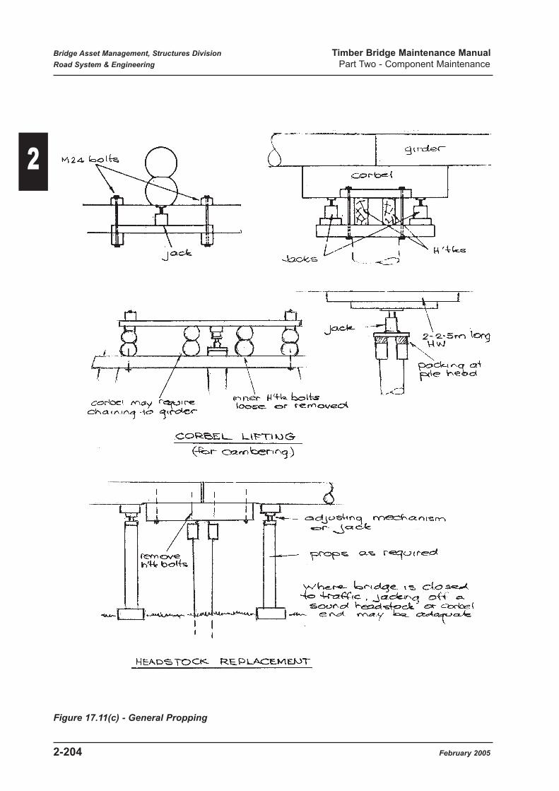
Figure 17.11(c) - General Propping
Bridge Asset Management, Structures Division Timber Bridge Maintenance Manual
Road System & Engineering Part Two - Component Maintenance
2-204 February 2005
2