
PART TD DESIGN REQUIREMENTS Article TD-1 General … xii/SEC XII- PART TD.pdf · PART TD DESIGN...
34
PART TD DESIGN REQUIREMENTS Article TD-1 General Design Rules TD-100 GENERAL The design of all pressure vessels and vessel parts shall conform to the general design requirements in the following paragraphs. For vessels in a specific service, the additional requirements of the applicable Modal Appendix shall also be met. TD-100.1 Minimum Thickness of Shells and Heads Unless otherwise specified in the applicable Modal Appendices, the minimum thickness permitted for ves- sel shells and heads, after forming and regardless of product form and material, shall be 1.6 mm ( 1 / 16 in.) exclusive of any corrosion allowance. TD-100.2 Mill Under-Tolerance Plate material ordered shall be not thinner than the minimum required design thickness. Vessels made of plate furnished with an under-tolerance of not more than the smaller value of 0.25 mm (0.01 in.) or 6% of the ordered thickness may be used at the full design pressure for the thickness ordered. If the specification to which the plate is ordered allows a greater under- tolerance, the ordered thickness of the materials shall be sufficiently greater than the design thickness so that the thickness of the material furnished is not more than the smaller of 0.25 mm (0.01 in.) or 6% under the mini- mum required design thickness. TD-100.3 Pipe Under-Tolerance If pipe or tube is ordered by its nominal wall thickness, the manufacturing under-tolerance on wall thickness shall be taken into account, except for nozzle wall rein- forcement area requirements in accordance with TD-610. The next heavier commercial wall thickness may then be used. The manufacturing under-tolerances are given in the pipe and tube specifications listed in Table TG- 130. After the minimum required design thickness is determined, it shall be increased by an amount sufficient to provide the manufacturing under-tolerance allowed in the pipe or tube specification. 56 TD-100.4 Corrosion Allowance in Design Formulas The dimensional symbols used in all design formulas throughout this Section represent dimensions in the cor- roded condition. TD-100.5 Flanges and Pipe Fittings The following standards covering flanges and pipe fittings are acceptable for use under this Section in accor- dance with the requirements of TM-110.10. Pressure- temperature ratings shall be in accordance with the appropriate standard, except that the pressure-tempera- ture ratings for ASME B16.9 and ASME B16.11 fittings shall be calculated for straight seamless pipes in accor- dance with the rules of this Section, including the maxi- mum allowable stress for the material. The thickness tolerances of the ASME standards listed in TG-130 shall be met. TD-110 METHODS OF FABRICATION IN COMBINATION A vessel may be designed and constructed by a combi- nation of the methods of fabrication given in this Section, provided the rules applying to the respective methods of fabrication are followed and the vessel is limited to the service permitted by the method of fabrication hav- ing the most restrictive requirements. TD-120 MATERIALS IN COMBINATION Except as specifically prohibited by other rules of this Section, a vessel may be designed and constructed of any combination of materials, provided the applicable rules are followed and the requirements in Section IX for welding dissimilar metals are met. NOTE: Because of the different coefficients of thermal expansion of dissimilar materials, caution should be exercised in design and construction under the provisions of this paragraph, in order to avoid difficulties in service. Galvanic corrosion, if a possibility, shall also be considered. Copyright ASME International Provided by IHS under license with ASME No reproduction or networking permitted without license from IHS --`,,```,,,,````-`-`,,`,,`,`,,`---
Transcript of PART TD DESIGN REQUIREMENTS Article TD-1 General … xii/SEC XII- PART TD.pdf · PART TD DESIGN...

PART TDDESIGN REQUIREMENTS
Article TD-1General Design Rules
TD-100 GENERAL
The design of all pressure vessels and vessel partsshall conform to the general design requirements in thefollowing paragraphs. For vessels in a specific service,the additional requirements of the applicable ModalAppendix shall also be met.
TD-100.1 Minimum Thickness of Shells and Heads
Unless otherwise specified in the applicable ModalAppendices, the minimum thickness permitted for ves-sel shells and heads, after forming and regardless ofproduct form and material, shall be 1.6 mm (1⁄16 in.)exclusive of any corrosion allowance.
TD-100.2 Mill Under-Tolerance
Plate material ordered shall be not thinner than theminimum required design thickness. Vessels made ofplate furnished with an under-tolerance of not morethan the smaller value of 0.25 mm (0.01 in.) or 6% ofthe ordered thickness may be used at the full designpressure for the thickness ordered. If the specificationto which the plate is ordered allows a greater under-tolerance, the ordered thickness of the materials shallbe sufficiently greater than the design thickness so thatthe thickness of the material furnished is not more thanthe smaller of 0.25 mm (0.01 in.) or 6% under the mini-mum required design thickness.
TD-100.3 Pipe Under-Tolerance
If pipe or tube is ordered by its nominal wall thickness,the manufacturing under-tolerance on wall thicknessshall be taken into account, except for nozzle wall rein-forcement area requirements in accordance with TD-610.The next heavier commercial wall thickness may thenbe used. The manufacturing under-tolerances are givenin the pipe and tube specifications listed in Table TG-130. After the minimum required design thickness isdetermined, it shall be increased by an amount sufficientto provide the manufacturing under-tolerance allowedin the pipe or tube specification.
56
TD-100.4 Corrosion Allowance in Design Formulas
The dimensional symbols used in all design formulasthroughout this Section represent dimensions in the cor-roded condition.
TD-100.5 Flanges and Pipe Fittings
The following standards covering flanges and pipefittings are acceptable for use under this Section in accor-dance with the requirements of TM-110.10. Pressure-temperature ratings shall be in accordance with theappropriate standard, except that the pressure-tempera-ture ratings for ASME B16.9 and ASME B16.11 fittingsshall be calculated for straight seamless pipes in accor-dance with the rules of this Section, including the maxi-mum allowable stress for the material. The thicknesstolerances of the ASME standards listed in TG-130 shallbe met.
TD-110 METHODS OF FABRICATION INCOMBINATION
A vessel may be designed and constructed by a combi-nation of the methods of fabrication given in this Section,provided the rules applying to the respective methodsof fabrication are followed and the vessel is limited tothe service permitted by the method of fabrication hav-ing the most restrictive requirements.
TD-120 MATERIALS IN COMBINATION
Except as specifically prohibited by other rules of thisSection, a vessel may be designed and constructed ofany combination of materials, provided the applicablerules are followed and the requirements in Section IXfor welding dissimilar metals are met.
NOTE: Because of the different coefficients of thermal expansionof dissimilar materials, caution should be exercised in design andconstruction under the provisions of this paragraph, in order toavoid difficulties in service. Galvanic corrosion, if a possibility,shall also be considered.
Copyright ASME International Provided by IHS under license with ASME
Not for ResaleNo reproduction or networking permitted without license from IHS
--`,,```,,,,````-`-`,,`,,`,`,,`---

TD-130 TD-160PART TD — DESIGN REQUIREMENTS
TD-130 CORROSION
(a) The User or his designated agent shall specifycorrosion allowances other than those required by therules of this Section. Where corrosion allowances are notprovided, this fact shall be indicated on the Data Report.
(b) Vessels or parts of vessels subject to thinning bycorrosion, erosion, or mechanical abrasion shall haveprovisions made for the desired life of the vessel by asuitable increase in the minimum required design thick-ness of the material.
(c) No additional thickness need be provided whenprevious experience in like service has shown that corro-sion does not occur or is of only a superficial nature.
(d) Vessels subject to corrosion shall be supplied witha suitable drain opening at the lowest point practicablein the vessel.
(e) Corrosion-resistant or abrasion-resistant linings,whether or not attached to the wall of a vessel, shall notbe considered as contributing to the strength of the wall.
TD-140 DESIGN TEMPERATURE
(a) The maximum temperature used in design shallbe not less than the mean metal temperature (throughthe thickness) expected under operating conditions forthe part considered. If necessary, the metal temperatureshall be determined by computation or by measurementfrom equipment in service under equivalent operatingconditions.
(b) The minimum metal temperature specified fordesign shall be the lowest expected in service. The mini-mum specified metal temperature shall be determinedby the principles described in TD-140(a). Considerationshall include the lowest operating temperature, opera-tional upsets, autorefrigeration, atmospheric tempera-ture, and any other sources of cooling. More than oneset of minimum metal temperature and correspondingdesign pressures may be specified.
(c) Design temperatures listed in excess of the maxi-mum temperatures listed in the stress allowable tables
57
for Section XII construction are not permitted (see TD-210 and the applicable Modal Appendices). In addition,design temperatures for vessels under external pressureshall not exceed the maximum temperatures given onthe external pressure charts.
(d) The design of zones with different metal tempera-tures may be based on their determined temperatures.
TD-150 DESIGN PRESSURES
Vessels shall be designed for at least the most severecondition of coincident pressure and temperatureexpected in normal operation. For this condition andfor test conditions, the maximum difference in pressurebetween the inside and outside of a vessel shall be con-sidered. More than one set of design pressure and corres-ponding design temperature may be specified.
TD-160 MAWP
(a) The Maximum Allowable Working Pressure(MAWP) for a vessel is the maximum pressure permissi-ble at the top of the vessel in its normal operating posi-tion at the designated coincident temperature. It is theleast of the values of MAWP calculated for any of theessential parts of the vessel by the principles given inTD-160(b), and adjusted for any difference in static anddynamic head that may exist between the part consid-ered and the top of vessel.
(b) The MAWP for a vessel part is the maximum inter-nal or external pressure, including the coincident staticand dynamic head, as determined by the rules and for-mulas in this Section, together with the effect of anycombination of loadings listed in TD-200, for the desig-nated coincident temperature (excluding corrosionallowance, see TD-130).
(c) MAWP may need to be determined for more thanone designated combination of pressure and temper-ature.
(d) See the applicable Modal Appendix for additionalrequirements on MAWP.
Copyright ASME International Provided by IHS under license with ASME
Not for ResaleNo reproduction or networking permitted without license from IHS
--`,,```,,,,````-`-`,,`,,`,`,,`---

Article TD-2Loadings and Stress Allowables
TD-200 LOADINGS
Vessels that are constructed under the rules of thisSection shall be designed to withstand the loadings thatare expected from the vessel’s use as both a stationaryvessel and as a vessel subjected to inertial forces (includ-ing vibratory forces) specified in the applicable ModalAppendices.
(a) Primary Design Loads. The loadings for which avessel shall be designed shall include those from
(1) internal or external design pressure (as definedin TD-150), including the additional pressure due tostatic head of liquids
(2) weight of the vessel and normal contents underoperating or test conditions
(3) superimposed static reactions from the weightof attached equipment, such as motors, machinery, othervessels, piping, linings, and insulation
(4) the attachment of(a) internals (see Nonmandatory Appendix B)(b) vessel supports, such as lugs, rings, skirts,
saddles, support rails, and legs (see NonmandatoryAppendix A)
(5) cyclic and dynamic reactions due to pressure orthermal variations, or to equipment mounted on a vesseland/or motor vehicle, and mechanical loadings
(6) liquid surge reactions(7) temperature gradients and differential thermal
expansion(8) additional loads as defined in the applicable
Modal Appendices(b) Additional Dynamic Loads. Inertial forces acting on
vessels while being transported in service shall be evalu-ated as equivalent static loads as required for each modewhere
Ci, Cj,Ck p factors that shall be multiplied by the weight
of the fully loaded vessel, Wv, to determinethe corresponding inertial static equivalentvector loadings in the indicated directions.These factors shall be determined in combi-nation or individually as required by theapplicable Modal Appendix.
CN p surge vector reduction factor correspondingto number of baffles or other surgerestraining devices, N. This factor shall bedetermined according to the most stringentof the User’s requirements or the minimum
58
requirements of the Competent Authority.(See Mandatory Appendix III.)
Cs p factor that shall be multiplied by weight ofthe liquid contents of the vessel, Wc, to deter-mine the static equivalent surge vector, Fs.This factor shall be determined from theappropriate Modal Appendix to the trans-portation mode for which the vessel isdesigned.
Fi p static equivalent vector force directed alongthe direction of travel
Fj p static equivalent net vector force in the verti-cal direction
Fk p static equivalent vector force directed hori-zontally normal to the expected directionof travel
Fs p static equivalent vector force directedagainst the vessel wall due to forward surgeof liquid contents in relation to the vessel
i p subscript denoting horizontal loads andstatic equivalent inertial force vectorsdirected parallel to expected direction of for-ward travel
j p subscript denoting loads and static equiva-lent inertial force and weight vectorsdirected vertically
k p subscript denoting horizontal loads andstatic equivalent inertial force vectorsdirected normal (lateral) to expected direc-tion of travel in the horizontal plane
N p the surge retardation number used to deter-mine CN, equal to the number of baffles orother surge-restraining devices that are con-sidered to effectively retard the movementof liquid contents of the vessel relative tothe vessel wall in the expected direction offorward travel
Wc p weight of the liquid contents of the vesselWv p weight of the vessel, its contents and the
weight of all equipment, structures or otheritems listed in TD-200(a)(2), (3), and (4) thatare supported by the vessel during oper-ation
(1) requirements for application of static equivalentinertial load vectors in relation to orientation of theprincipal axes of a vessel in motion are:
Copyright ASME International Provided by IHS under license with ASME
Not for ResaleNo reproduction or networking permitted without license from IHS
--`,,```,,,,````-`-`,,`,,`,`,,`---

TD-200 TD-210PART TD — DESIGN REQUIREMENTS
(a) horizontal vectors directed parallel toexpected direction of travel
Fi p CiWv
(b) static equivalent inertial vectors directedvertically
Fj p CjWv
(c) horizontal vectors directed normal (lateral) toexpected direction of travel
Fk p CkWv
(d) static equivalent vector force directed againstthe vessel wall due to surge of liquid contents in relationto the vessel
Fs p CNWc
(2) Vessels constructed for portable or intermodalservice or for service wherein the direction of travel withrelation to one or more of the vessel’s principal axes isunknown shall be designed to withstand static equiva-lent inertial vector loads in directions normal and paral-lel to the direction of the meridional or longitudinal axisof the vessel that are determined as follows:
Fi p Fk p CiWv
(3) Reaction force vectors resulting from applica-tion of all combinations of loads to the vessel [includingstatic equivalent inertial loadings according to therequirements of TD-200(b)(1) and (2)], shall be deter-mined for each location of structural attachment to thevessel. The loading effect of these reactions on the vesselshall be evaluated and combined as required by theapplicable Modal Appendix.
TD-210 MAXIMUM ALLOWABLE STRESS VALUES
(a) The maximum allowable tensile stress values per-mitted for different materials are given in Section II, PartD, Subpart 1. (For the basis on which the tabulated stressvalues have been established, see Appendix 1 of SectionII, Part D.) The allowable stress values given in Subpart1 of Section II, Part D for Section VIII, Division 1 shallbe used in the design of tanks for this Section. A listingof materials allowed for construction under this Sectionis provided in Part TM.
(b) The maximum allowable stress values for the addi-tional loads in TD-200(a)(8) are defined in the applicableModal Appendices.
(c) The maximum allowable longitudinal compres-sive stress to be used in the design of cylindrical shellsor tubes, either seamless or butt welded, subjected toloadings that produce longitudinal compression in theshell or tube shall be the smaller of the following values:
59
(1) the maximum allowable tensile stress value per-mitted in TD-210(a)
(2) the value of the factor B determined by the fol-lowing procedure
whereE p modulus of elasticity of material at design tem-
perature. The modulus of elasticity to be usedshall be taken from the applicable materialschart in Section II, Part D, Subpart 2. (Interpola-tion may be made between lines for intermedi-ate temperatures.)
Ro p outside radius of cylindrical shell or tubet p the minimum required thickness of the cylin-
drical shell or tube
The joint efficiency for butt-welded joints shall betaken as unity.
The value of B shall be determined as follows:Step 1. Using the selected values of t and R, calculate
the value of factor A using the followingequation:
A p0.125(Ro/t)
Step 2. Using the value of A calculated in Step 1, enterthe applicable material chart in Section II, PartD, Subpart 3 for the material under consider-ation. Move vertically to an intersection withthe material/temperature line for the designtemperature. Interpolation may be madebetween lines for intermediate temperatures.In cases where the value at A falls to the rightof the end of the material/temperature line,assume an intersection with the horizontalprojection of the upper end of the material/temperature line. For values of A falling tothe left of the material/temperature line, seeStep 4.
Step 3. From the intersection obtained in Step 2, movehorizontally to the right and read the valueof factor B. This is the maximum allowablecompressive stress for the values of t and Rused in Step 2.
Step 4. For values of A falling to the left of the applica-ble material/temperature line, the value of Bshall be calculated using the followingequation:
B pAE2
Step 5. Compare the value of B determined in Step 3 or4 with the computed longitudinal compressivestress in the cylindrical shell or tube, using theselected values of t and R. If the value of B issmaller than the computed compressive stress,a greater value of t must be selected and thedesign procedure repeated until a value of B
Copyright ASME International Provided by IHS under license with ASME
Not for ResaleNo reproduction or networking permitted without license from IHS
--`,,```,,,,````-`-`,,`,,`,`,,`---

TD-210 TD-2102004 SECTION XII
is obtained, which is greater than the compres-sive stress computed for the loading on thecylindrical shell or tube.
(d) The wall thickness of a vessel calculated by theserules shall be determined such that, for any combinationof loadings listed in TD-200 that induce primary stressand are expected to occur simultaneously during normaloperation of the vessel, the induced maximum generalprimary membrane stress does not exceed the maximumallowable stress value in tension [see TD-210(a)]. Theabove loads shall not induce a combined maximum pri-mary membrane stress plus primary bending stress
60
across the thickness, which exceeds 11⁄2 times the maxi-mum allowable stress value in tension. It is recognizedthat high localized discontinuity stresses may exist invessels designed and fabricated in accordance with theserules. Insofar as practical, design rules for details havebeen written to limit such stresses to a safe level consist-ent with experience.
The maximum allowable stress values that are to beused in the thickness calculations are to be taken fromthe tables at the temperature that is expected to be main-tained in the metal under the conditions of loading beingconsidered. Maximum allowable stress values may beinterpolated for intermediate temperatures.
Copyright ASME International Provided by IHS under license with ASME
Not for ResaleNo reproduction or networking permitted without license from IHS
--`,,```,,,,````-`-`,,`,,`,`,,`---

Article TD-3Design for Internal Pressure
TD-300 THICKNESS OF SHELLS UNDER INTERNALPRESSURE
The thickness of shells under internal pressure shallbe not less than that computed by the equations in TD-300.2 through TD-300.5. In addition, provisions shall bemade for any of the other loadings listed in TD-200,when such loadings are expected.
TD-300.1 Nomenclature
The symbols defined below are used in the equationsof TD-300.2 through TD-300.5.
E p joint efficiency for, or the efficiency of, appro-priate joint in cylindrical or spherical shells.(For welded vessels, use the joint efficienciesspecified in TW-130.4.)
P p internal design pressure (see TD-150)R p inside radius of the shell course under consid-
eration. For pipe, the inside radius R is deter-mined by the nominal outside radius minusthe nominal wall thickness. For conical shellswith half apex angle not exceeding 7 deg, theconical radius at the large end of each sectionshall be used.
Ro p outside radius of the shell course under consid-eration. For conical shells with half apex anglenot exceeding 7 deg, the conical radius at thelarge end of each section shall be used.
S p maximum allowable stress value (see TD-210)t p minimum required thickness of shell
TD-300.2 Cylindrical Shells
The minimum required design thickness or maximumallowable working pressure of cylindrical shells and con-ical shells with half apex angle not exceeding 7 deg shallbe the greater thickness or lesser pressure as given byTD-300.2(a) or (b).
(a) Circumferential Stress (Longitudinal Joints). Whenthe thickness does not exceed one-half of the insideradius, or P does not exceed 0.385SE, the following equa-tions shall apply:
t pPR
SE − 0.6Por P p
SEtR + 0.6t
(b) Longitudinal Stress (Circumferential Joints). Whenthe thickness does not exceed one-half of the insideradius, or P does not exceed 1.25SE, the following equa-tions shall apply:
61
t pPR
2SE + 0.4tor P p
2SEtR − 0.4t
TD-300.3 Spherical Shells
When the thickness of the shell of a wholly sphericalvessel does not exceed 0.356R, or P does not exceed0.665SE, the following equations shall apply:
t pPR
2SE − 0.2Por P p
2SEtR + 0.2t
TD-300.4 Local Loadings
When necessary, vessels shall be provided with stif-feners or other additional means of support to preventoverstress or large distortions under the external load-ings listed in TD-200 other than pressure and temper-ature.
TD-300.5 Equations in Terms of Outside Radius
The following equations in terms of outside radiusmay be used:
(a) for cylindrical shells (circumferential stress)
t pPRo
SE + 0.4Por P p
SEtRo − 0.8t
(b) for spherical shells
t pPRo
2SE + 0.8Por P p
2SEtRo − 0.8t
TD-310 FORMED HEADS AND SECTIONS,PRESSURE ON CONCAVE SIDE
The required thickness at the thinnest point after form-ing of ellipsoidal, torispherical, and hemispherical headsunder pressure on the concave side (plus heads) shallbe computed by the appropriate formulas in this para-graph. In addition, provision shall be made for any ofthe other loadings given in TD-200.
The thickness of an unstayed ellipsoidal or torispheri-cal head shall in no case be less than the required thick-ness of a seamless hemispherical head divided by theefficiency of the head-to-shell joint.
TD-310.1 Nomenclature
The symbols defined below are used in equationsin TD-310.1 through TD-310.4. Figure TD-310.1 showsprinciple dimensions of typical heads.
Copyright ASME International Provided by IHS under license with ASME
Not for ResaleNo reproduction or networking permitted without license from IHS
--`,,```,,,,````-`-`,,`,,`,`,,`---

TD-310.1 TD-310.62004 SECTION XII
Fig. TD-310.1 Principal Dimensions of Typical Heads
D p inside diameter of the head skirt, or insidelength of the major axis of an ellipsoidal head
E p lowest efficiency of any joint in the head; forhemispherical heads, this includes head-to-shell joint; for welded vessels, use the jointefficiencies specified in TW-130.4
ERT p modulus of elasticity at 20°C (70°F)EST p modulus of elasticity of steel at 20°C (70°F)ET p modulus of elasticity at maximum design tem-
peratureh p one-half of the length of the minor axis of the
ellipsoidal head or the inside depth of theellipsoidal head measured from the tangentline
L p inside spherical or crown radiusP p internal design pressure (see TD-150)r p inside knuckle radiusS p maximum allowable stress value in tension as
given in the tables referenced in TD-210t p minimum required design thickness of head
after forming
TD-310.2 Torispherical Heads
The minimum required thickness of a torisphericalhead having 0.002 ≤ t/L ≤ 0.06 shall be the larger of thethicknesses calculated by eqs. (1) and (2). These equa-tions are based on the assumption that the number of fullpressurization cycles does not exceed 400. Any pressurecycle exceeding 20% of the range of full pressure cycleshall be considered as an equivalent full pressure cycle.[If the number of equivalent pressure cycles exceeds 400,see TG-100.2(c) and Section VIII, Divisions 1 and 2.]
t pPLM
2SE − 0.2P(1)
t p3PLKERT
4SaET(2)
The value of Sa shall be 115,000 psi for all materialsexcept for aluminum, aluminum alloys, copper, copper
62
alloys, titanium, and zirconium, for which the value ofSa shall be calculated by eq. (3).
Sa p115,000ERT
EST(3)
The value of M shall be obtained from Table TD-310.2-1. Interpolation may be used for r/D values that fallwithin the range of the tabulated values. No extrapola-tion of the values is permitted.
The value of K shall be obtained from Table TD-310.2-2. Interpolation may be used for r/D values that fallwithin the range of the tabulated values. No extrapola-tion of the values is permitted.
TD-310.3 Ellipsoidal Heads
The minimum required thickness of an ellipsoidalhead with D/2h ratio less than or equal to 2.0 shall beestablished as an equivalent torispherical head using therules given in TD-310.2. An acceptable approximationof a 2:1 ellipsoidal head is a torispherical head with aknuckle radius of 0.17D and a spherical radius of 0.9D.
TD-310.4 Hemispherical Heads
When the thickness of a hemispherical head does notexceed 0.356L, or P does not exceed 0.665SE, the follow-ing equations shall apply:
t pPL
2SE − 0.2Por P p
2SEtL + 0.2t
TD-310.5 Crown and Knuckle Radii
The inside crown radius to which an unstayed headis dished shall not be greater than the outside diameterof the skirt of the head. The inside knuckle radius of atorispherical head shall be not less than 6% of the outsidediameter of the skirt of the head but in no case less thanthree times the head thickness.
TD-310.6 Thickness Transition and Tapers
All formed heads, thicker than the shell and concaveto pressure, intended for butt-welded attachment, shall
Copyright ASME International Provided by IHS under license with ASME
Not for ResaleNo reproduction or networking permitted without license from IHS
--`,,```,,,,````-`-`,,`,,`,`,,`---

TD-310.6 TD-310.7PART TD — DESIGN REQUIREMENTS
Table TD-310.2-1 Values for M
M for M for M for M fort/L r/D p 0.06 r/D p 0.07 r/D p 0.08 0.08 < r/D ≤ 0.2
0.002 1.00 1.00 1.00 1.000.004 1.00 1.00 1.00 1.000.006 1.28 1.00 1.00 1.000.008 1.41 1.20 1.00 1.000.010 1.41 1.26 1.10 1.000.012 1.38 1.25 1.13 1.000.016 1.31 1.21 1.12 1.000.020 1.25 1.17 1.08 1.000.030 1.14 1.08 1.01 1.000.040 1.07 1.01 1.00 1.000.060 1.00 1.00 1.00 1.00
Table TD-310.2-2 Values for K
K for K for K for K for K for K fort/L r/D p 0.06 r/D p 0.08 r/D p 0.10 r/D p 0.14 r/D p 0.17 r/D p 0.20
0.002 7.87 6.29 5.24 3.95 3.31 2.810.004 6.77 5.60 4.69 3.49 2.93 2.500.006 6.04 5.14 4.38 3.27 2.73 2.330.008 5.51 4.78 4.14 3.13 2.60 2.210.010 5.11 4.49 3.93 3.02 2.51 2.130.012 4.79 4.25 3.76 2.93 2.44 2.060.016 4.31 3.87 3.47 2.77 2.33 1.970.020 3.96 3.58 3.24 2.63 2.24 1.910.030 3.48 3.10 2.84 2.37 2.07 1.790.040 3.32 2.97 2.69 2.23 1.95 1.720.060 3.12 2.80 2.56 2.17 1.92 1.71
have a skirt length sufficient to meet the requirementsof Fig. TW-130.5-1, when a tapered transition is required.All formed heads concave to pressure and intended forbutt-welded attachment need not have an integral skirtwhen the thickness of the head is equal to or less thanthe thickness of the shell. When a skirt is provided, itsthickness shall be at least that required for a seamlessshell of the same diameter.
Any taper at a welded joint within a formed headshall be in accordance with TW-130.5. The taper at a
63
circumferential welded joint connecting a formed headto a main shell shall meet the requirements of TW-130.5for the respective type of joint shown therein.
TD-310.7 Flat Spots
If a torispherical, ellipsoidal, or hemispherical headis formed with a flattened spot or surface, the diameterof the flat spot shall not exceed that permitted for flatheads as given by eq. (1) in TD-500(c), using C p 0.25.
Copyright ASME International Provided by IHS under license with ASME
Not for ResaleNo reproduction or networking permitted without license from IHS
--`,,```,,,,````-`-`,,`,,`,`,,`---

Article TD-4Design for External Pressure
TD-400 THICKNESS OF SHELLS UNDER EXTERNALPRESSURE
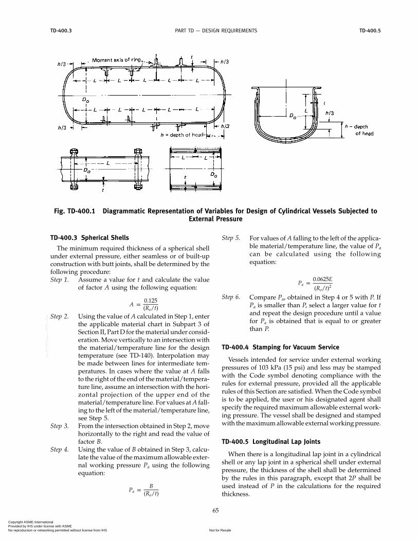
Rules for the design of shells under external pressuregiven in this Section are limited to cylindrical shells,with or without stiffening rings, and spherical shells.Three typical forms of cylindrical shells are shown inFig. TD-400.1. Charts used in determining minimumrequired thickness of these components are given inSubpart 3 of Section II, Part D.
TD-400.1 Nomenclature
The symbols defined below are used in the proceduresof this paragraph (see Fig. TD-400.1):
A p factor determined from Fig. G in Subpart 3 ofSection II, Part D and used to enter the applica-ble material chart in Subpart 3 of Section II,Part D
B p factor determined from the applicable materialchart in Subpart 3 of Section II, Part D for maxi-mum design metal temperature
Do p outside diameter of cylindrical shell courseE p modulus of elasticity of material at design tem-
perature. For external pressure design in accor-dance with this Section, the modulus ofelasticity to be used shall be taken from theapplicable materials chart in Subpart 3 of Sec-tion II, Part D. (Interpolation may be madebetween lines for intermediate temperatures.)
L p design length of a vessel section between linesof support. A line of support is a:
(a) circumferential line on a head (excludingconical heads) at one-third the depth of the headfrom the head tangent line as shown on Fig.TD-400.1
(b) stiffening ring that meets the require-ments of TD-410.1
P p external design pressure (see TD-150)Pa p calculated value of maximum allowable exter-
nal working pressure for the assumed value of tRo p outside radius of spherical shell
t p minimum required thickness of cylindrical shellor tube or spherical shell
ts p nominal thickness of cylindrical shell or tube
TD-400.2 Cylindrical Shells
The required minimum thickness of a cylindrical shellhaving Do/t values not less than 10, under external pres-sure, shall be determined by the following procedure:
64
Step 1. Assume a value for t and determine the ratiosL/Do and D/t.
Step 2. Enter Fig. G in Subpart 3 of Section II, Part Dat the value of L/Do determined in Step 1. Forvalues of L/Do greater than 50, enter the chartat a value of L/Do p 50. For values of L/Doless than 0.05, enter the chart at a value ofL/Do p 0.05.
Step 3. Move horizontally to the line for the value ofDo/t determined in Step 1. Interpolation maybe made for intermediate values of Do/t. Fromthis point of intersection, move verticallydownward to determine the value of factor A.
Step 4. Using the value of A calculated in Step 3, enterthe applicable material chart in Subpart 3 ofSection II, Part D for the material under consid-eration. Move vertically to an intersection withthe material/temperature line for the designtemperature. Interpolation may be madebetween lines for intermediate temperatures.In cases where the value of A falls to the rightof the end of the material/temperature line,assume an intersection with the horizontalprojection of the upper end of the material/temperature line. For values of A falling tothe left of the material/temperature line, seeStep 7.
Step 5. From the intersection obtained in Step 4, movehorizontally to the right and read the value offactor B.
Step 6. Using this value of B, calculate the value ofthe maximum allowable external workingpressure, Pa, using the following equation:
Pa p4B
3(Do/t)
Step 7. For values of A falling to the left of the applica-ble material/temperature line, the value of Pa
can be calculated using the followingequation:
Pa p2AE
3(Do/t)
Step 8. Compare the calculated value of Pa obtainedin Step 6 or 7 with P. If Pa is smaller than P,select a larger value for t and repeat the designprocedure until a value of Pa is obtained thatis equal to or greater than P.
Copyright ASME International Provided by IHS under license with ASME
Not for ResaleNo reproduction or networking permitted without license from IHS
--`,,```,,,,````-`-`,,`,,`,`,,`---
TD-400.3 TD-400.5PART TD — DESIGN REQUIREMENTS
Fig. TD-400.1 Diagrammatic Representation of Variables for Design of Cylindrical Vessels Subjected toExternal Pressure
TD-400.3 Spherical Shells
The minimum required thickness of a spherical shellunder external pressure, either seamless or of built-upconstruction with butt joints, shall be determined by thefollowing procedure:Step 1. Assume a value for t and calculate the value
of factor A using the following equation:
A p0.125(Ro/t)
Step 2. Using the value of A calculated in Step 1, enterthe applicable material chart in Subpart 3 ofSection II, Part D for the material under consid-eration. Move vertically to an intersection withthe material/temperature line for the designtemperature (see TD-140). Interpolation maybe made between lines for intermediate tem-peratures. In cases where the value at A fallsto the right of the end of the material/tempera-ture line, assume an intersection with the hori-zontal projection of the upper end of thematerial/temperature line. For values at A fall-ing to the left of the material/temperature line,see Step 5.
Step 3. From the intersection obtained in Step 2, movehorizontally to the right and read the value offactor B.
Step 4. Using the value of B obtained in Step 3, calcu-late the value of the maximum allowable exter-nal working pressure Pa using the followingequation:
Pa pB
(Ro/t)
65
Step 5. For values of A falling to the left of the applica-ble material/temperature line, the value of Pa
can be calculated using the followingequation:
Pa p0.0625E
(Ro/t)2
Step 6. Compare Pa, obtained in Step 4 or 5 with P. IfPa is smaller than P, select a larger value for tand repeat the design procedure until a valuefor Pa is obtained that is equal to or greaterthan P.
TD-400.4 Stamping for Vacuum Service
Vessels intended for service under external workingpressures of 103 kPa (15 psi) and less may be stampedwith the Code symbol denoting compliance with therules for external pressure, provided all the applicablerules of this Section are satisfied. When the Code symbolis to be applied, the user or his designated agent shallspecify the required maximum allowable external work-ing pressure. The vessel shall be designed and stampedwith the maximum allowable external working pressure.
TD-400.5 Longitudinal Lap Joints
When there is a longitudinal lap joint in a cylindricalshell or any lap joint in a spherical shell under externalpressure, the thickness of the shell shall be determinedby the rules in this paragraph, except that 2P shall beused instead of P in the calculations for the requiredthickness.
Copyright ASME International Provided by IHS under license with ASME
Not for ResaleNo reproduction or networking permitted without license from IHS
--`,,```,,,,````-`-`,,`,,`,`,,`---

TD-400.6 TD-410.12004 SECTION XII
TD-400.6 Circumferential Joints
Circumferential joints in cylindrical shells, unlessotherwise prohibited by the rules of this Section, maybe of any type permitted by the Code and shall bedesigned for the imposed loads.
TD-400.7 External Loadings
When necessary, vessels shall be provided with stif-feners or other additional means of support to preventoverstress or large distortions under the external load-ings listed in TD-200 other than pressure and temper-ature.
TD-400.8 External Pressure
The external design pressure or maximum allowableexternal working pressure shall be not less than themaximum expected difference in operating pressure thatmay exist between the outside and the inside of thevessel at any time.
TD-410 STIFFENING RINGS FOR CYLINDRICALSHELLS UNDER EXTERNAL PRESSURE
TD-410.1 Required Moment of Inertia
Except as exempted in Step 6a, the available momentof inertia of a circumferential stiffening ring shall be notless than that determined by one of the following twoequations:
Is p [D2oLs(t + As/Ls)A]/14
Is′ p [D2oLs(t + As/Ls)A]/10.9
I p available moment of inertia of the stiffeningring cross section about its neutral axis parallelto the axis of the shell
I′ p available moment of inertia of combined ringshell cross section about its neutral axis parallelto the axis of the shell. The nominal shell thick-ness, t, shall be used and the width of shell thatis taken as contributing to the moment of inertiaof the combined section shall be not greaterthan 1.10�Dots and shall be taken as lying one-half on each side of the centroid of ring. Portionsof the shell plate shall not be considered ascontributing area to more than one stiffeningring.
Is p required moment of inertia of the stiffening ringcross section about its neutral axis parallel tothe axis of the shell
Is′ p required moment of inertia of the combinedring-shell cross section about its neutral axisparallel to the axis of the shell
If the stiffeners should be so located that the maximumpermissible effective shell sections overlap on either orboth sides of a stiffener, the effective shell section for that
66
stiffener shall be shortened by one-half of each overlap.A p factor determined from the applicable chart in
Subpart 3 of Section II, Part D for the materialused in the stiffening ring, corresponding tothe factor B, below, and the design temperaturefor the shell under consideration
As p cross-sectional area of the stiffening ringB p factor determined from the applicable chart in
Subpart 3 of Section II, Part D for the materialused for the stiffening ring
Ls p one-half of the distance from the center line ofthe stiffening ring to the next line of supporton one side, plus one-half of the center linedistance to the next line of support on the otherside of the stiffening ring, both measured paral-lel to the axis of the cylinder. A line of support is
(a) a stiffening ring that meets the require-ments of this paragraph
(b) a circumferential connection to a jacketfor a jacketed section of a cylindrical shell
(c) a circumferential line on a head at one-third the depth of the head from the head tan-gent line as shown on Fig. TD-400.1.
P, Do, E, t, and ts are as defined in TD-400.1.The adequacy of the moment of inertia for a stiffening
ring shall be determined by the following procedure:Step 1. Assuming that the shell has been designed
and Do, Ls, and t are known, select a memberto be used for the stiffening ring and deter-mine its cross-sectional area, As. Then calcu-late factor B using the following equation:
B p34 � PDo
t + As/Ls�Step 2. Enter the right-hand side of the applicable
material chart in Subpart 3 of Section II, PartD for the material under consideration at thevalue of B determined by Step 1. If differentmaterials are used for the shell and stiffeningring, use the material chart resulting in thelarger value of A in Step 4, below.
Step 3. Move horizontally to the left to the material/temperature line for the design metal temper-ature. For values of B falling below the leftend of the material/temperature line, seeStep 5.
Step 4. Move vertically to the bottom of the chartand read the value of A.
Step 5. For values of B falling below the left end ofthe material/temperature line for the designtemperature, the value of A can be calculatedusing the equation A p 2B/E.
Step 6a. In those cases where only the stiffening ringis considered, compute the required momentof inertia from the equation for Is given inTD-410.1.
Copyright ASME International Provided by IHS under license with ASME
Not for ResaleNo reproduction or networking permitted without license from IHS
--`,,```,,,,````-`-`,,`,,`,`,,`---

TD-410.1 TD-420PART TD — DESIGN REQUIREMENTS
Step 6b. In those cases where the combined ring shellis considered, compute the required momentof inertia from the equation for Is′ given inTD-410.1.
Step 7a. In those cases where only the stiffening ringis considered, determine the availablemoment of inertia I as given in the defini-tions.
Step 7b. In those cases where the combined ring shellis considered, determine the availablemoment of inertia I′ as given in the defini-tions.
NOTE: In those cases where the stiffening ring is not attached tothe shell or where the stiffening ring is attached but the designerchooses to consider only the ring, Steps 6a and 7a are to be used.In those cases where the stiffening ring is attached to the shell andthe combined moment of inertia is considered, Steps 6b and 7bare to be used.Step 8. If the required moment of inertia is greater
than the available moment of inertia for thesection selected, for those cases where thestiffening ring is not attached or where thecombined ring-shell stiffness was not consid-ered, a new section with a larger moment ofinertia must be selected; the ring must beattached to the shell and the combinationshall be considered; or the ring-shell combi-nation that was previously not consideredtogether shall be considered together. If therequired moment of inertia is greater than theavailable moment of inertia for those caseswhere the combined ring-shell was consid-ered, a new ring section with a larger momentof inertia must be selected. In any case, whena new section is used, all of the calculationsshall be repeated using the new section prop-erties of the ring or ring-shell combination.
If the required moment of inertia is smaller than theavailable moment of inertia, whichever method is used,that ring section or combined section is satisfactory.
CAUTIONARY NOTE: Stiffening rings may be subject to lateralbuckling. This should be considered in addition to the require-ments for Is and Is′.
TD-410.2 Stiffening Ring Arrangement
Stiffening rings shall extend completely around thecircumference of the cylinder, except as permitted below.Any joints between the ends or sections of such rings,such as shown in Fig. TD-410.2-1,(A) and (B), and anyconnection between adjacent portions of a stiffening ringlying inside or outside the shell as shown in Fig.TD-410.2-1 shall be made so that the required moment ofinertia of the combined ring-shell section is maintained.
Stiffening rings placed on the inside of a vessel maybe arranged as shown in Fig. TD-410.2-1, (E) and (F),provided that the required moment of inertia of the ring
67
in (E) or of the combined ring-shell section in (F) ismaintained within the sections indicated. Where the gapat (A) or (E) does not exceed eight times the thicknessof the shell plate, the combined moment of inertia ofthe shell and stiffener may be used.
Any gap in that portion of a stiffening ring supportingthe shell, such as shown in Fig. TD-410.2-1, (E), shallnot exceed the length of arc given in Fig. TD-410.2-2unless additional reinforcement is provided as shownin Fig. TD-410.2-1 or unless the following conditionsare met:
(a) only one unsupported shell arc is permitted perring
(b) the length of the unsupported shell arc does notexceed 90 deg
(c) the unsupported arcs in adjacent stiffening ringsare staggered 180 deg
(d) the dimension L defined in TD-400.1 is taken as thelarger of the following: the distance between alternatestiffening rings, or the distance from the head tangentline to the second stiffening ring plus one-third of thehead depth.
TD-410.3 Internal Structures as Stiffeners andSupports
When internal plane structures perpendicular to thelongitudinal axis of the cylinder (such as bubble traysor baffle plates) are used in a vessel, they may also beconsidered to act as stiffening rings, provided they aredesigned to function as such.
Any internal stays or supports used as stiffeners ofthe shell shall bear against the shell of the vessel throughthe medium of a substantially continuous ring.
TD-420 ATTACHMENT OF STIFFENING RINGS FOREXTERNAL PRESSURE
(a) Stiffening rings may be placed on the inside oroutside of a vessel, and shall be attached to the shell bywelding. The ring shall be essentially in contact withthe shell. Welding of stiffening rings shall comply withthe requirements of this Section for the type of vesselunder construction.
(b) Stiffening rings may be attached to the shell bycontinuous, intermittent, or a combination of continuousand intermittent welds. Some acceptable methods ofattaching stiffener rings are illustrated in Fig. TD-420.
(c) Intermittent welding shall be placed on both sidesof the stiffener and may be either staggered or in-line.Length of individual fillet weld segments shall be notless than 50 mm (2 in.) and shall have a maximum clearspacing between toes of adjacent weld segments of 8tfor external rings and 12t for internal rings where t isthe shell thickness at the attachment. The total lengthof weld on each side of the stiffening ring shall be
Copyright ASME International Provided by IHS under license with ASME
Not for ResaleNo reproduction or networking permitted without license from IHS
--`,,```,,,,````-`-`,,`,,`,`,,`---

PART TD — DESIGN REQUIREMENTS
Fig. TD-410.2-1 Various Arrangements of Stiffening Rings for Cylindrical Vessels Subjected to ExternalPressure
68
Copyright ASME International Provided by IHS under license with ASME
Not for ResaleNo reproduction or networking permitted without license from IHS
--`,,```,,,,````-`-`,,`,,`,`,,`---

TD-420 TD-430PART TD — DESIGN REQUIREMENTS
Fig. TD-410.2-2 Minimum Arc of Shell Left Unsupported Because of Gap in Stiffening Ring of CylindricalShell Under External Pressure
(1) not less than one-half the outside circumferenceof the vessel for rings on the outside. and
(2) not less than one-third the circumference of thevessel for rings on the inside
(d) A continuous full-penetration weld is permittedas shown in sketch (e) of Fig. TD-420. Continuous filletwelding on one side of the stiffener with intermittentwelding on the other side is permitted for sketches (a),(b), (c), and (d) of Fig. TD-420 when the thickness tw ofthe outstanding stiffener element [sketches (a) and (c)]or width w of the stiffener element mating to the shell[sketches (b) and (d)] is not more than 25 mm (1 in.).The weld segments shall be not less than 50 mm (2 in.)long and shall have a maximum clear spacing betweentoes of adjacent weld segments of 24t.
(e) Strength of Attachment Welds. Stiffener ring attach-ment welds shall be sized to resist the full radial pressureload from the shell between stiffeners, and shear loadsacting radially across the stiffener caused by externaldesign loads carried by the stiffener (if any) and a com-puted radial shear equal to 2% of the stiffener ring’scompressive load.
69
(1) The radial pressure load from shell is equal toPLs.
(2) The radial shear load is equal to 0.01PLsDo.(3) P, Ls, and Do are defined in TD-400.1 (see TD-
410.1 for definitions).(f) Minimum Size of Attachment Welds. The fillet weld
leg size shall be not less than the smallest of the fol-lowing:
(1) 6 mm (1⁄4 in.)(2) vessel thickness at weld location(3) stiffener thickness at weld location
TD-430 FORMED HEADS, PRESSURE ON CONVEXSIDE
(a) General. The required thickness at the thinnestpoint after forming of ellipsoidal, torispherical, andhemispherical heads under pressure on the convex side(minus heads) shall be computed by the appropriateformulas given in this paragraph. In addition, provisionsshall be made for any other loading referenced in TD-200. The required thickness for heads due to pressure
Copyright ASME International Provided by IHS under license with ASME
Not for ResaleNo reproduction or networking permitted without license from IHS
--`,,```,,,,````-`-`,,`,,`,`,,`---

2004 SECTION XII
Shell
Stiffener
Continuous full penetration weld
S 8t external stiffenersS 12t internal stiffeners
(a) (b)
S
50 mm (2 in.) min.
tw
w
S
50 mm (2 in.) min.
50 mm (2 in.) min.
24t max.
tw
twt
w
(c)
Continuous Fillet Weld
One Side, Intermittent
Other Side
Staggered
Intermittent
Weld
In-line
Intermittent
Weld
tw
(d) (e)
w
tw
t
Fig. TD-420 Some Acceptable Methods of Attaching Stiffening Rings
70
Copyright ASME International Provided by IHS under license with ASME
Not for ResaleNo reproduction or networking permitted without license from IHS
--`,,```,,,,````-`-`,,`,,`,`,,`---

TD-430 TD-430PART TD — DESIGN REQUIREMENTS
Table TD-430 Values of Spherical RadiusFactor Ko for Ellipsoidal Head With Pressure
on Convex Side
Do/2ho . . . 3.0 2.8 2.6 2.4 2.2Ko . . . 1.36 1.27 1.18 1.08 0.99
Do/2ho 2.0 1.8 1.6 1.4 1.2 1.0Ko 0.90 0.81 0.73 0.65 0.57 0.50
GENERAL NOTE: Interpolation permitted for intermediate values.
on the convex side shall be determined as follows:(1) For ellipsoidal and torispherical heads, the
required thickness shall be the greater of the following:(a) the thickness computed by the procedure
given in TD-310 for heads with pressure on the concaveside (plus heads) using a design pressure 1.67 times thedesign pressure on the convex side, assuming a jointefficiency E p 1.00 for all cases
(b) the thickness as computed by the appropriateprocedure given in TD-430(d) or (e)
(2) For hemispherical heads, the required thicknessshall be determined by the rules given in TD-430(c).
(b) Nomenclature. The nomenclature defined below isused in this paragraph. See Fig. TD-310.1.
A, B, E, and P are as defined in TD-400.1.Do p outside diameter of the head skirt
Do/2ho p ratio of the major to the minor axis of ellip-soidal heads, which equals the outsidediameter of the head skirt divided by twicethe outside height of the head (see TableTD-430)
ho p one-half of the length of the outside minoraxis of the ellipsoidal head, or the outside
71
height of the ellipsoidal head measuredfrom the tangent line (head-bend line)
Ko p factor depending on the ellipsoidal headproportions, Do/2ho, (see Table TD-430)
Ro p for hemispherical heads, the outside radiusp for ellipsoidal heads, the equivalent outside
spherical radius taken as KoDop for torispherical heads, the outside radius
of the crown portion of the headT p minimum required thickness of head after
forming
(c) Hemispherical Heads. The required thickness of ahemispherical head having pressure on the convex sideshall be determined in the same manner as outlined inTD-400.3 for determining the thickness for a sphericalshell.
(d) Ellipsoidal Heads. The required thickness of anellipsoidal head having pressure on the convex side,either seamless or of built-up construction with buttjoints, shall be not less than that determined by thefollowing procedure.Step 1. Assume a value for t and calculate the value
of factor A using the following equation:
A p0.125Ro/t
Step 2. Using the value of A calculated in Step 1, fol-low the same procedure as that given forspherical shells in TD-400.3, Steps 2 through 6.
(e) Torispherical Heads. The required thickness of a tori-spherical head having pressure on the convex side, eitherseamless or of built-up construction with butt joints,shall be not less than that determined by the same designprocedure as is used for ellipsoidal heads given in TD-430(d), using the appropriate value for Ro.
Copyright ASME International Provided by IHS under license with ASME
Not for ResaleNo reproduction or networking permitted without license from IHS
--`,,```,,,,````-`-`,,`,,`,`,,`---

Article TD-5Unstayed Flat Heads and Covers
TD-500 DESIGN OF UNSTAYED FLAT HEADS ANDCOVERS
(a) The minimum thickness of unstayed flat heads,cover plates, and blind flanges shall conform to therequirements given in this paragraph. These require-ments apply to both circular and noncircular heads andcovers. Special consideration shall be given to the designof shells, nozzle necks, or flanges to which noncircularheads or covers are attached. Some acceptable types offlat heads and covers are shown in Fig. TD-500. In thisfigure, the dimensions of the component parts and thedimensions of the welds are exclusive of extra metalrequired for corrosion allowance.
(b) The symbols used in this paragraph and in Fig.TD-500 are defined as follows:
C p a factor depending upon the method of attach-ment of head, shell dimensions, and other itemsas listed in TD-500(d), dimensionless. The fac-tors for welded covers also include a factor of0.667 that effectively increases the allowablestress for such constructions to 1.5S
D p long span of noncircular heads or covers mea-sured perpendicular to short span
d p diameter, or short span, measured as indicatedin Fig. TD-500
E p joint efficiency, from Table TW-130.4, of any Cat-egory A weld as defined in TW-130.3
hG p gasket moment arm, equal to the radial distancefrom the centerline of the bolts to the line ofthe gasket reaction, as shown in Table 2-5.2 ofSection VIII, Div. 1
L p perimeter of noncircular bolted head measuredalong the centers of the bolt holes
M p the ratio tr/ts, dimensionlessP p internal design pressure (see TD-150)r p inside comer radius on a head formed by flang-
ing or forgingS p maximum allowable stress value in tension, psi,
from applicable table of stress values referencedby TD-210
t p minimum required design thickness of flat heador cover
tf p nominal thickness of the flange on a forgedhead, at the large end, as indicated in Fig. TD-500, sketch (b)
th p nominal thickness of flat head or cover
72
tr p required thickness of seamless shell, forpressure
ts p nominal thickness of shelltw p thickness through the weld joining the edge of
a head to the inside of a vessel, as indicated inFig. TD-500, sketch (g)
t1 p throat dimension of the closure weld, as indi-cated in Fig. TD-500, sketch (r)
W p total bolt load, given for circular heads for eqs.(3) and (4), 2–5(e) of Section VIII, Div. 1.
Y p length of flange of flanged heads, measuredfrom the tangent line of knuckle, as indicatedin Fig. TD-500, sketches (a) and (c)
Z p a factor of noncircular heads and covers thatdepends on the ratio of short span to long span,as given in TD-500(c), dimensionless
(c) The thickness of flat unstayed heads, covers, andblind flanges shall conform to one of the following threerequirements. These equations provide adequate designmargins against structural failure. However, no limit hasbeen provided for deflection and rotation. If leakage ata threaded or gasketed joint is of concern, the thicknessmay have to be increased to provide adequate rotationalstiffness.
(1) Circular blind flanges conforming to any of theflange standards listed in Table TG-130 and further lim-ited in TD-100.5 shall be acceptable for the diameters andpressure-temperature ratings in the respective standardwhen the blind flange is of the types shown in Fig. TD-500, sketches (j) and (k).
(2) The minimum required thickness of flatunstayed circular heads, covers, and blind flanges shallbe calculated by the following equation:
t p d�CP/SE (1)
except when the head, cover, or blind flange is attachedby bolts causing an edge moment [sketches (j) and (k)],in which case the thickness shall be calculated by
t p �CPSE
+1.9WHG
SEd3(2)
When using eq. (2), the thickness t shall be calculatedfor both operating conditions and gasket seating, andthe greater of the two values shall be used. For operatingconditions, the value of P shall be the design pressure,and the values of S at the design temperature and W
Copyright ASME International Provided by IHS under license with ASME
Not for ResaleNo reproduction or networking permitted without license from IHS
--`,,```,,,,````-`-`,,`,,`,`,,`---

PART TD — DESIGN REQUIREMENTS
ts ts
tsts t
ts
tf
d d
d
Yt
t tt
C = 0.17 orC = 0.10
(a)
C = 0.13
(d)
C = 0.33mC min. = 0.20
(i)
C = 0.3[Use Eq. (2) or (5)]
(j)
C = 0.3[Use Eq. (2) or (5)]
(k)
C = 0.33
(h)
C = 0.30
C = 0.25
C = 0.75
C = 0.33 C = 0.33
C = 0.30 C = 0.30(m)
(p)
(q)
(r) (s)
(n) (o)
(e) (f) (g)
C = 0.33mC min. = 0.20
(b-2)
Continuation of shell optional
Sketches (e), (f), and (g) circular covers, C = 0.33m, Cmin. = 0.20
See Fig. TW-130.5-2 sketches (a) to (g), inclusive, for details of welded joint ts not less than 1.25tr
See Fig. TW-130.5-2 sketches (a) to (g), inclusive, for details of outside welded joint
Threaded ring
30 deg min.45 deg max.
Seal weld
When pipe threads are used, see Table TD-670
0.8ts min.3/4t min.
ormin. t1 = t or ts whichever is greater
Retaining ring
rmin. = 10 mm (0.375 in.) for ts 38 mm (11/2 in.) rmin. = 0.25ts for ts 38 mm (11/2 in.) but need not be greater than 3/4 19 mm (in.)
C = 0.17
(b-1)
Center of weld
Taper
Tangent line
r = 3t min.
d
Y
tsts
t
ts ts
tst1
d
t
hG
tt dddd
d d d
hG
d
Projection beyond weld is optional
Bevel is optional
45 deg max.
tw = 2tr min. nor less than 1.2ts but need not be greater than t
tf min. = 2ts
0.7ts0.7ts0.7ts
0.7ts
0.7ts
t
C = 0.30C = 0.20 or 0.13
(c)
Center of lap
Tangent line
r = 3t min.
r = 3tf min.
r = 1/4t min.
t
t t t
ddd
dd
d
ttt
t
t
t
t
t
GENERAL NOTE: The above sketches are diagrammatic only. Other designs that meet the requirements of TD-500 areacceptable.
Fig. TD-500 Some Acceptable Types of Unstayed Flat Heads and Covers
73
Copyright ASME International Provided by IHS under license with ASME
Not for ResaleNo reproduction or networking permitted without license from IHS
--`,,```,,,,````-`-`,,`,,`,`,,`---

TD-500 TD-5002004 SECTION XII
from eq. (3) of 2-5(e) of Section VIII, Div. 1 shall be used.For gasket seating, P equals zero, and the values of Sat atmospheric temperature and W from eq. (4) of 2-5(e)of Section VIII, Div. 1 shall be used.
(3) Flat unstayed heads, covers, or blind flangesmay be square, rectangular, elliptical, obround, segmen-tal, or otherwise noncircular. Their required thicknessshall be calculated by the following equation:
t p d�ZCP/SE (3)
where
Z p 3.4 −2.4d
D(4)
with the limitation that Z need not be greater than 2.5.Equation (3) does not apply to noncircular heads, cov-
ers, or blind flanges attached by bolts causing a bolt edgemoment [sketches (j) and (k)]. For noncircular heads ofthis type, the required thickness shall be calculated bythe following equation:
t p d�ZCPSE
+6Whg
SELd2(5)
When using eq. (5), the thickness t shall be calculatedin the same way as specified above for eq. (2).
(d) For the types of construction shown in Fig. TD-500, the minimum values of C to be used in eqs. (1), (2),(3), and (5) are:
(1) Sketch (a)(a) C p 0.17 for flanged circular and noncircular
heads forged integral with or butt welded to the vesselwith an inside corner radius not less than three timesthe required head thickness, with no special requirementwith regard to length of flange, and where the weldingmeets all the requirements for circumferential jointsgiven in Part TW.
(b) C p 0.10 for circular heads, when the flangelength for heads of the above design is not less than
Y p �1.1 − 0.8t2s
t2h� �dth (6)
(c) C p 0.10 for circular heads, when the flangelength Y is less than the requirements in eq. (6) but theshell thickness is not less than
ts p 1.12th�1.1 − Y/�dth (7)
for a length of at least 2�dts.When C p 0. 10 is used, the taper shall be at least 1:3.
(2) Sketch (b-1). C p 0.17 for forged circular andnoncircular heads integral with or butt-welded to thevessel, where the flange thickness is not less than twotimes the shell thickness, the corner radius on the insideis not less than three times the flange thickness, and the
74
welding meets all the requirements for circumferentialjoints given in Part TW.
(3) Sketch (b-2). C p 0.33m but not less than 0.20for forged circular and noncircular heads integral withor butt-welded to the vessel, where the flange thicknessis not less than the shell thickness, the corner radius onthe inside is not less than the following:
(a) rmin p 10 mm (0.375 in.) for ts ≤ 38 mm (11⁄2 in.)(b) rmin p 0.25t, for ts > 38 mm (11⁄2 in.) but need
not be greater than 19 mm (3⁄4 in.)The welding shall meet all the requirements for cir-
cumferential joints given in Part TW.(4) Sketch (c)
(a) C p 0.13 for circular heads lap-welded to theshell with corner radius not less than 3t and Y not lessthan required by eq. (6) and the requirements of TW-130.5 are met.
(b) C p 0.20 for circular and noncircular lapwelded or brazed construction as above, but with nospecial requirement with regard to Y.
(c) C p 0.30 for circular flanged plates screwedover the end of the vessel, with inside comer radius notless than 3t, in which the design of the threaded jointagainst failure by shear, tension, or compression,resulting from the end force due to pressure, is basedon a factor of safety of at least 3.5, and the threadedparts are at least as strong as the threads for standardpiping of the same diameter. Seal welding may be used,if desired.
(5) Sketch (d). C p 0.13 for integral flat circularheads when the dimension d does not exceed 610 mm (24in.), the ratio of thickness of the head to the dimension dis not less than 0.05 or greater than 0.25, the head thick-ness th is not less than the shell thickness ts, the insidecorner radius is not less than 0.25t, and the constructionis obtained by special techniques of upsetting and spin-ning the end of the shell, such as employed in closingheader ends.
(6) Sketches (e), (f), and (g)(a) C p 0.33m but not less than 0.20 for circular
plates, welded to the inside of a vessel, and otherwisemeeting the requirements for the respective types ofwelded vessels. If a value of m < 1 is used in calculating t,the shell thickness ts shall be maintained along a distanceinwardly from the inside face of the head equal to atleast 2�dts. The throat thickness of the fillet welds insketches (e) and (f) shall be at least 0.7ts. The size of theweld tw in sketch (g) shall be not less than two timesthe required thickness of a seamless shell nor less than1.25 times the nominal shell thickness but need not begreater than the head thickness; the weld shall be depos-ited in a welding groove with the root of the weld atthe inner face of the head as shown in the sketch.
(b) C p 0.33 for noncircular plates, welded to theinside of a vessel and otherwise meeting the require-ments for the respective types of welded vessels. The
Copyright ASME International Provided by IHS under license with ASME
Not for ResaleNo reproduction or networking permitted without license from IHS
--`,,```,,,,````-`-`,,`,,`,`,,`---

TD-500 TD-500PART TD — DESIGN REQUIREMENTS
throat thickness of the fillet welds in sketches (e) and(f) shall be at least 0.7ts. The size of the weld tw in sketch(g) shall be not less than two times the required thicknessof a seamless shell nor less than 1.25 times the nominalshell thickness but need not be greater than the headthickness; the weld shall be deposited in a weldinggroove with the root of the weld at the inner face of thehead as shown in the sketch.
(7) Sketch (h). C p 0.33 for circular plates weldedto the end of the shell when ts is at least 1.25tr and theweld details conform to the requirements of TW-130.5(e)and Fig. TW-130.5-2, sketches (a) through (g) inclusive.
(8) Sketch (i). C p 0.33m but not less than 0.20 forcircular plates if an inside fillet weld with minimumthroat thickness of 0.7ts is used and the details of theoutside weld conform to the requirements of TW-130.5(e)and Fig. TW-130.5-2, sketches (a) through (g) inclusive,in which the inside weld can be considered to contributean amount equal to ts to the sum of the dimensions aand b.
(9) Sketches (j) and (k). C p 0.3 for circular andnoncircular heads and covers bolted to the vessel asindicated in the figures. Note that eq. (2) or (5) shall beused because of the extra moment applied to the coverby the bolting.
When the cover plate is grooved for a peripheral gas-ket, as shown in sketch (k), the net cover plate thicknessunder the groove or between the groove and the outeredge of the cover plate shall be not less than
d�1.9WhG/Sd3
for circular heads and covers, and not less than
d�6WhG/SLd2
for noncircular heads and covers.(10) Sketches (m), (n), and (o). C p 0.3 for a circular
plate inserted into the end of a vessel and held in placeby a positive mechanical locking arrangement, and
75
when all possible means of failure (either by shear, ten-sion, compression, or radial deformation, including flar-ing, resulting from pressure and differential thermalexpansion) are resisted with a design margin of at least3.5. Seal welding may be used, if desired.
(11) Sketch (p). C p 0.25 for circular and noncircularcovers bolted with a full-face gasket, to shells, flanges,or side plates.
(12) Sketch (q). C p 0.75 for circular plates screwedinto the end of a vessel having an inside diameter d notexceeding 305 mm (12 in.); or for heads having an inte-gral flange screwed over the end of a vessel having aninside diameter d not exceeding 305 mm (12 in.); andwhen the design of the threaded joint, against failureby shear, tension, compression, or radial deformation,including flaring, resulting from pressure and differen-tial thermal expansion, is based on a factor of safetyof at least 3.5. If a tapered pipe thread is used, therequirements of Table TD-670 shall also be met. Sealwelding may be used, if desired.
(13) Sketch (r). C p 0.33 for circular plates havinga dimension d not exceeding 457 mm (18 in.) insertedinto the vessel as shown and otherwise meeting therequirements for the respective types of welded vessels.The end of the vessel shall be crimped over at least 30deg, but not more than 45 deg. The crimping may bedone cold only when this operation will not injure themetal. The throat of the weld shall be not less than thethickness of the flat head or shell, whichever is greater.
(14) Sketch (s). C p 0.33 for circular beveled plateshaving a diameter d not exceeding 457 mm (18 in.),inserted into a vessel, the end of which is crimped overat least 30 deg, but not more than 45 deg, and when theundercutting for seating leaves at least 80% of the shellthickness. The beveling shall be not less than 75% of thehead thickness. The crimping shall be done when theentire circumference of the cylinder is uniformly heatedto the proper forging temperature for the material used.For this construction, the ratio ts/d shall be not less thanthe ratio P/S nor less than 0.05. The maximum allowablepressure for this construction shall not exceed P p S/5d.
This construction is not permissible if machined fromrolled plate.
Copyright ASME International Provided by IHS under license with ASME
Not for ResaleNo reproduction or networking permitted without license from IHS
--`,,```,,,,````-`-`,,`,,`,`,,`---

Article TD-6Openings and Reinforcements
TD-600 OPENINGS IN TRANSPORT TANKS
TD-600.1 Shape of Openings
(a) Openings in cylindrical or conical portions of ves-sels, or in formed heads, shall preferably be circular,elliptical, or obround. (The opening made by a pipe orcircular nozzle, the axis of which is not perpendicularto the vessel wall or head, may be considered an ellipticalopening for design purposes.) An obround opening isone that is formed by two parallel sides and semicircu-lar ends.
When the long dimension of an elliptical or obroundopening exceeds twice the short dimension, the rein-forcement across the short dimension shall be increasedas necessary to provide against excessive distortion dueto twisting moment.
(b) For openings of other shapes than those given inTD-600.1(a), all corners shall be provided with a suitableradius. When the openings are of such proportions thattheir strength cannot be computed with assurance ofaccuracy, or when doubt exists as to the safety of a vesselwith such openings, the part of the vessel affected shallbe subjected to a proof hydrostatic test as prescribed inTT-210.
TD-600.2 Size of Openings
(a) Properly reinforced openings in cylindrical or con-ical shells are not limited as to size, except with thefollowing provisions for design. The rules of TD-600.2through TD-610.6 apply to all openings, unlessexempted by other rules of this Section. For openingshaving a diameter exceeding the following, the supple-mental rules of TD-610.7 shall also be satisfied:
(1) for vessels 1 520 mm (60 in.) inside diameterand less, one-half the vessel diameter, or 508 mm (20 in.)
(2) for vessels over 1 520 mm (60 in.) inside diame-ter, one-third the vessel diameter, or 1 000 mm (40 in.)
(b) Properly reinforced openings in spherical shellsand formed heads are not limited in size.
TD-600.3 Strength and Design of Finished Openings
(a) All references to dimensions in this and suc-ceeding paragraphs apply to the finished constructionafter deduction has been made for material added ascorrosion allowance. For design purposes, corrosionallowance shall not be considered as reinforcement. Thefinished opening diameter is the diameter d as definedin TD-610.1 and in Fig. TD-610.3-2.
76
(b) Openings in cylindrical or conical shells, orformed heads shall be reinforced to satisfy the require-ments in TD-610.3, except as given in TD-600.3(c).
Openings in flat heads shall be reinforced as requiredby TD-630.
(c) Openings in vessels not subject to rapid fluctua-tions in pressure do not require reinforcement other thanthat inherent in the construction under the followingconditions:
(1) welded connections and flued openingsattached in accordance with the applicable rules andwith a finished opening not larger than:
(a) 89 mm (31⁄2 in.) diameter, in vessel shells orheads having a required minimum design thickness of10 mm (3⁄8 in.) or less
(b) 60 mm (23⁄8 in.) diameter, in vessel shells orheads having a required minimum design thickness ofover 10 mm (3⁄8 in.)
(2) threaded, studded, or expanded connections inwhich the hole cut in the shell or head is not greaterthan 60 mm (23⁄8 in.)
(3) no two isolated unreinforced openings, in accor-dance with TD-600.2(a)(1) or (2), shall have their centerscloser to each other than the sum of their diameters
(4) no two unreinforced openings, in a cluster ofthree or more unreinforced openings in accordance withTD-600.2(a)(1) or (2), shall have their centers closer toeach other than the following:
(a) for cylindrical or conical shells
(1 + 1.5 cos �) (d1 + d2)
(b) for doubly curved shells and formed or flatheads
2.5(d1 + d2)
where� p the angle between the line connecting the
center of the openings and the longitudinalaxis of the shell
d1, d2 p the finished diameters of the two adjacentopenings
TD-600.4 Openings Through Welded Joints
Additional provisions governing openings in or adja-cent to welded joints are given in TW-140.1.
Copyright ASME International Provided by IHS under license with ASME
Not for ResaleNo reproduction or networking permitted without license from IHS
--`,,```,,,,````-`-`,,`,,`,`,,`---

TD-600.5 TD-610.1PART TD — DESIGN REQUIREMENTS
TD-600.5 Openings in Noncircular Vessels
Openings in noncircular vessels are not covered bythese rules, except for formed heads. See TG-100.2(c).
TD-610 REINFORCEMENT REQUIRED FOROPENINGS IN SHELLS AND FORMEDHEADS
TD-610.1 Nomenclature
The symbols used in this paragraph are defined asfollows (see Fig. 610.3-2):
A p total cross-sectional area of reinforcementrequired in the plane under consideration
A1 p area in excess thickness in the vessel wallavailable for reinforcement
A2 p area in excess thickness in the nozzle wallavailable for reinforcement
A3 p area available for reinforcement when thenozzle extends inside the vessel wall
A5 p cross-sectional area of material added asreinforcement
A41, A42,A43 p cross-sectional area of various welds
available for reinforcementc p corrosion allowanced p finished diameter of circular opening or
finished dimension (chord length at mids-urface of thickness excluding excess thick-ness available for reinforcement) ofnonradial opening in the plane under con-sideration (see Fig. TD-640)
D p inside shell diameterDp p outside diameter of reinforcing element
(actual size of reinforcing element mayexceed the limits of reinforcement estab-lished by TD-640; however, credit cannotbe taken for any material outside theselimits)
E p 1 (see definitions for tr and trn)E1 p 1 when the opening is in the solid plate
or in the Category B butt joint, orp joint efficiency obtained from Table TW-
130.4, when any part of the opening pas-ses through any other welded joint
F p correction factor that compensates for thevariation in pressure stresses on differentplanes with respect to the longitudinalaxis of a vessel. Fp1.0 for formed or flatheads (see Fig. TD-610.3-1).
fr p strength reduction factor, not greater than1.0 [see TD-650(a)]
fr1 p Sn/Sv for nozzle wall inserted through thevessel wall
p 1.0 for nozzle wall abutting the vessel walland for nozzles shown in Fig. TD-640,sketches (j), (k), (n), and (o).
77
Table TD-610.1 Values of Spherical Radius FactorK1
D/2h . . . 3.0 2.8 2.6 2.4 2.2K1 . . . 1.36 1.27 1.18 1.08 0.99
D/2h 2.0 1.8 1.6 1.4 1.2 1.0K1 0.90 0.81 0.73 0.65 0.57 0.50
GENERAL NOTE: Equivalent spherical radius p K1D; D/ 2h p axisratio. For definitions, see TD-610.1. Interpolation permitted for inter-mediate values.
fr2 p Sn/Svfr3 p (lesser of Sn or Sp)/Svfr4 p Sp/Svh p distance nozzle projects inward from the
inner surface of the vessel wall. (Extensionof the nozzle beyond the inside surface ofthe vessel wall is not limited; however,for reinforcement calculations, credit shallnot be taken from material outside thelimits of reinforcement established byTD-640.)
K1 p spherical radius factor (see definition oftr and Table TD-610.1)
L p length of projection defining the thick-ened portion of integral reinforcement ofa nozzle neck beyond the outside surfaceof the vessel wall [see Fig. TD-640,sketch (e)]
P p internal design pressure (see TD-150)R p inside radius of the shell course under
considerationRn p inside radius of the nozzle under
considerationS p allowable stress value in tension (see
TD-210)Sn p allowable stress in nozzle (see S above)Sv p allowable stress in vessel (see S above)Sp p allowable stress in reinforcing element
(see S above)t p nominal thickness of the vessel wall
te p thickness or height of reinforcing element,(see Fig. TD-640)
ti p nominal thickness of internal projectionof nozzle wall
tn p nominal thickness of external projectionof nozzle wall
tr p required thickness of a seamless shellbased on the circumferential stress, or ofa formed head, computed by the rules ofthis Section for the designated pressure,using E p 1, except that:
(a) when the opening and its reinforce-ment are entirely within the spherical por-tion of a torispherical head, tr is the
Copyright ASME International Provided by IHS under license with ASME
Not for ResaleNo reproduction or networking permitted without license from IHS
--`,,```,,,,````-`-`,,`,,`,`,,`---

TD-610.1 TD-610.72004 SECTION XII
thickness required by TD-300.3, usingM p 1
(b) when the opening is in a cone, tr isthe thickness required for a seamless coneof diameter D measured where the nozzleaxis pierces the inside wall of the cone
(c) when the opening and its reinforce-ment are in an ellipsoidal head and arelocated entirely within a circle, the centerof which coincides with the center of thehead and the diameter of which is equalto 80% of the shell diameter, tr is the thick-ness required for a seamless sphere ofradius K1D, where D is the shell diameterand K1 is given by Table TD-610.1
trn p required thickness of a seamless nozzlewall
W p total load to be carried by attachmentwelds, lb (see TD-650)
TD-610.2 General
The rules in this paragraph apply to all openingsother than:
(a) small openings covered by TD-600.3(c)(b) openings in flat heads covered by TD-630Reinforcement shall be provided in amount and distri-
bution such that the area requirements for reinforcementare satisfied for all planes through the center of theopening and normal to the vessel surface. For a circularopening in a cylindrical shell, the plane containing theaxis of the shell is the plane of greatest loading due topressure. Not less than half the required reinforcementshall be on each side of the centerline of single openings.
TD-610.3 Design for Internal Pressure
The total cross-sectional area of reinforcement, A,required in any given plane through the opening for ashell or formed head under internal pressure shall benot less than
A p dtrF + 2tntrF (1 − fr1)
See Fig. TD-610.3-1 and Fig. TD-610.3-2.
TD-610.4 Design for External Pressure
(a) The reinforcement required for openings in single-walled vessels subject to external pressure need be only50% of that required in TD-610.3, where tr is the wallthickness required by the rules for vessels under externalpressure. The value of F shall be 1.0 in all external pres-sure calculations.
(b) The reinforcement required for openings in eachshell of a multiple-walled vessel shall comply with TD-610.4(a) when the shell is subject to external pressure,and with TD-610.3 when the shell is subject to internalpressure, regardless of whether or not there is a commonnozzle secured to more than one shell by strength welds.
78
GENERAL NOTE: F p3⁄4 + 1⁄4 cos (2�)
Fig. TD-610.3-1 Chart for Determining Value of F,as Required in TD-610.3
TD-610.5 Design for Both Internal and ExternalPressure
Reinforcement of vessels subject to both internal andexternal pressures shall meet the requirements of TD-610.3 for internal pressure and TD-610.4 for externalpressure.
TD-610.6 Area Replacement
Details and formulas for required area and availablearea are given in Fig. TD-610.3-2.
TD-610.7 Large Openings in Shells
(a) Openings exceeding the dimensional limits givenin TD-600.2(a)(1) shall be provided with reinforcementthat complies with the following rules. Two-thirds ofthe required reinforcement shall be within the followinglimits:
(1) parallel to vessel wall: the larger of three-fourthstimes the limit in TD-640, or equal to the limit inTD-640(b)(2)
Copyright ASME International Provided by IHS under license with ASME
Not for ResaleNo reproduction or networking permitted without license from IHS
--`,,```,,,,````-`-`,,`,,`,`,,`---

TD-610.7 TD-620PART TD — DESIGN REQUIREMENTS
(2) normal to the vessel wall the smaller of the limitin TD-640(c)(1), or in TD-640(c)(2)
(b) Openings for radial nozzles in cylindrical shellsthat exceed the limits in TD-600.2 and that also are withinthe range defined by the following limits shall meet therequirements of TD-610.7(c), (d), and (e):
(1) vessel diameters greater than 1 500 mm (60 in.)in diameter
(2) nozzle diameters that exceed 1 000 mm (40 in.)in diameter and also exceed 3.4�Rt. (The terms R andt are defined in Fig. TD-610.7).
(3) the ratio Rn/R does not exceed 0.7; [for nozzleopenings with Rn/R exceeding 0.7, refer to TD-610.7(c)and/or TG-100.2(c)]
These rules are limited to radial nozzles in cylindricalshells that do not have internal projections, and do nothave externally applied mechanical loads specified. Forcases that do not meet these limitations, a recognizedanalytical method shall be used. See TG-100.2(c).
(c) The membrane stress, Sm, as calculated by eq. (1)or (2) shall not exceed S, as defined in TD-610.1 for theapplicable materials at design conditions. The maximumcombined membrane stress, Sm, and bending stress, Sb,shall not exceed 1.5S at design conditions. Sb shall becalculated by eq. (5).
(d) Evaluation of combined stresses from internalpressure and external loads shall be made in accordancewith recognized good engineering practice for suchcases, such as the WRC-107/297 bulletins.
(e) For membrane stress calculations, use the limitsdefined in Fig. TD-610.7, and comply with the strengthof reinforcement requirements of TD-650. For bendingstress calculation, the greater of the limits defined inFig. TD-610.7 may be used. The strength reduction ratiorequirements of TD-650 need not be applied, providedthat the ratio of the allowable stress of the material inthe nozzle neck, nozzle forging, reinforcing plate, and/or nozzle flange to the shell material allowable stress isat least 0.80.NOTE: The bending stress, Sb, calculated by eq. (5) is valid andapplicable only at the nozzle neck-shell junction. It is a primarybending stress because it is a measure of the stiffness required tomaintain equilibrium at the longitudinal axis junction of the nozzle-shell intersection due to the bending moment calculated by eq. (3).
(1) Case A [see Fig. TD-610.7, sketches (a) and (c)]
Sm p P �R�Rn + tn + �Rmt� + Rn�t + te +�Rnmtn�As � (1)
(2) Case B [see Fig. TD-610.7, sketches (b) and (d)]
Sm p P �R�Rn + tn + �Rmt� + Rn�t + te +�Rnmtn�As � (2)
(3) Cases A and B (see Fig. TD-610.7)
M p �R3n
6+ RRne�P (3)
79
a p e + t/2 (4)
Sb pMa
I(5)
(f) Nomenclature. Symbols used in Fig. TD-610.7 areas defined in TD-610.7(a) and as follows:
a p distance between neutral axis of the shadedarea in Fig. TD-610.7 and the inside of ves-sel wall
As p shaded (cross-hatched) area in Fig. TD-610.7,sketch (a) or (b)
e p distance between neutral axis of the shadedarea and midwall of the shell
I p moment of inertia of the larger of the shadedareas in Fig. TD-610.7 and the inside of ves-sel wall
Rm p mean radius of shellRnm p mean radius of nozzle neck
Sb p bending stress at the intersection of inside ofthe nozzle neck and inside of the vessel shellalong the vessel shell longitudinal axis
Sm p membrane stress calculated by eq. (1) or (2)Sy p yield strength of the material at test tempera-
ture, see Table Y-1 in Subpart 1 of Section II,Part D
(g) It is recommended that special consideration begiven to the fabrication details used and inspectionemployed on large openings; reinforcement often maybe advantageously obtained by use of heavier shell platefor a vessel course or inserted locally around the open-ing; welds may be ground to concave contour and theinside corners of the opening rounded to a generousradius to reduce stress concentrations. When radio-graphic examination of welds is not practicable, liquidpenetrant may be used with nonmagnetic materials andeither liquid penetrant or magnetic particle inspectionwith ferromagnetic materials. If magnetic particleinspection is employed, the prod method is preferred.The degree to which such measures should be useddepends on the particular application and the severityof the intended service. Appropriate proof testing maybe advisable in extreme cases of large openingsapproaching full vessel diameter, openings of unusualshape, etc.
TD-610.8 Special Requirements
For additional requirements applicable to specific cat-egories of tanks, see the applicable Modal Appendices.
TD-620 FLUED OPENINGS IN SHELLS ANDFORMED HEADS
(a) Flued openings in shells and formed heads madeby inward or outward forming of the head plate shallmeet the requirements for reinforcement in TD-610. The
Copyright ASME International Provided by IHS under license with ASME
Not for ResaleNo reproduction or networking permitted without license from IHS
--`,,```,,,,````-`-`,,`,,`,`,,`---

2004 SECTION XII
GENERAL NOTE: This figure illustrates a common nozzle configuration and is not intended to prohibit other configurationspermitted by the Code.
Fig. TD-610.3-2 Nomenclature and Formulas for Reinforced Openings
80
Copyright ASME International Provided by IHS under license with ASME
Not for ResaleNo reproduction or networking permitted without license from IHS
--`,,```,,,,````-`-`,,`,,`,`,,`---

PART TD — DESIGN REQUIREMENTS
GENERAL NOTE: When any part of a flange is located within the greater of the �Rnmtn + te or 16tn + te limit as indicated inFig. TD-610.7 sketch (a) or (c), or the greater of �Rnmtn or 16tn for Fig. TD-610.7 sketch (b) or (d), the flange may beincluded as part of the section that resists bending moment.
Fig. TD-610.7 Openings for Radial Nozzles in Cylindrical Shells
81
Copyright ASME International Provided by IHS under license with ASME
Not for ResaleNo reproduction or networking permitted without license from IHS
--`,,```,,,,````-`-`,,`,,`,`,,`---

TD-620 TD-6302004 SECTION XII
Minimum depth of flange: the
smaller of 3tr or tr + 75 mm (3 in.)
when d exceeds 150 mm (6 in.)
d
Fig. TD-620 Minimum Depth for Flange of Fluedin Openings
thickness of the flued flange shall also meet the require-ments of Article TD-3 and/or Article TD-4 as applicable,where L as used in Article TD-4 is the minimum depthof flange as shown in Fig. TD-620. The minimum thick-ness of the flued flange on a vessel subject to both inter-nal and external pressure shall be the larger of the twothicknesses as determined above.
(b) The minimum depth of flange of a flued in open-ing exceeding 152 mm (6 in.) in any inside dimension,when not stayed by an attached pipe or flue, shall equal3tr or [tr + 75 mm (3 in.)], whichever is less, where tr isthe required shell or head thickness. The depth of flangeshall be determined by placing a straight edge acrossthe side opposite the flued opening along the major axisand measuring from the straight edge to the edge of theflanged opening (see Fig. TD-620).
(c) There is no minimum depth of flange requirementfor flued out openings.
(d) The minimum width of bearing surface for a gas-ket on a self-sealing flued opening shall be in accordancewith TD-690(f).
TD-630 REINFORCEMENT REQUIRED FOROPENINGS IN FLAT HEADS
(a) General. The rules in this paragraph apply to allopenings in flat heads, except opening(s) that do notexceed the size and spacing limits in TD-600.3(c)(3) anddo not exceed one-fourth the head diameter or short-est span.
(b) Single and multiple openings in flat heads thathave diameters equal to or less than one-half the headdiameter may be reinforced as follows:
(1) Flat heads that have a single opening with adiameter that does not exceed one-half the head diame-ter or shortest span, as defined in Article TD-5, shallhave a total cross-sectional area of reinforcement for all
82
planes through the center of the opening not less thanthat given by the formula
A p 0.5dt + ttn(1 − fr1)
where d, tn, and fr1 are defined in Article TD-5.(2) Multiple openings none of which have diame-
ters exceeding one-half the head diameter and no pairhaving an average diameter greater than one-quarterthe head diameter may be reinforced individually asrequired by TD-630(b)(1) when the spacing between anypair of adjacent openings is equal to or greater thantwice the average diameter of the pair.
When spacing between adjacent openings is less thantwice but equal to or more than 11⁄4 the average diameterof the pair, the required reinforcement for each openingin the pair, as determined by TD-630(b)(1), shall besummed together and then distributed such that 50%of the sum is located between the two openings. Spac-ings of less than 11⁄4 the average diameter of adjacentopenings shall be treated by rules of TG-100.2(c).
(c) As an alternative to TD-630(b)(l), the thicknessof flat heads and covers with a single opening with adiameter that does not exceed one-half the head diame-ter may be increased to provide the necessary reinforce-ment as follows:
(1) In eq. (1) or (3) of TD-500(c), use 2C or 0.75 inplace of C, whichever is the lesser; except that, forsketches (b-1), (b-2), (e), (f), (g), and (i) of Fig. TD-500,use 2C or 0.50, whichever is the lesser.
(2) In eq. (2) or (5) of TD-500(c), double the quantityunder the square root sign.
(d) Multiple openings none of which have diametersexceeding one-half the head diameter and no pair havingan average diameter greater than one-quarter the headdiameter may be reinforced as follows:
(1) When the spacing between a pair of adjacentopenings is equal to or greater than twice the averagediameter of the pair, and this is so for all opening pairs,the head thickness may be determined by rules in TD-630(c).
(2) When the spacing between adjacent openingsin a pair is less than twice but equal to or greater than11⁄4 the average diameter of the pair, the required headthickness shall be that determined by TD-630(c)multiplied by factor h, where
h p �0.5/e
e p [(p − davg)/p]smallest
wheredavg p average diameter of the same two adjacent
openingse p smallest ligament efficiency of adjacent open-
ing pairs in the headp p center-to-center spacing of two adjacent
openings
Copyright ASME International Provided by IHS under license with ASME
Not for ResaleNo reproduction or networking permitted without license from IHS
--`,,```,,,,````-`-`,,`,,`,`,,`---

TD-630 TD-650PART TD — DESIGN REQUIREMENTS
(3) Spacings of less than 11⁄4 the average diameterof adjacent openings shall be treated by rules of TG-100.2(c).
(4) In no case shall the width of ligament betweentwo adjacent openings be less than one-quarter thediameter of the smaller of the two openings in the pair.
(5) The width of ligament between the edge of anyone opening and the edge of the flat head shall not beless than one-quarter the diameter of that one opening.
TD-640 LIMITS OF REINFORCEMENT
(a) The boundaries of the cross-sectional area in anyplane normal to the vessel wall and passing through thecenter of the opening within which metal must belocated in order to have value as reinforcement are desig-nated as the limits of reinforcement for that plane (seeFig. TD-610.3-2). Figure TD-640 depicts thicknesses t, te,and tn, or ti and diameter d used in establishing thelimits of reinforcement.
(b) The limits of reinforcement, measured parallel tothe vessel wall, shall be at a distance, on each side of theaxis of the opening, equal to the greater of the following:
(1) the diameter d of the finished opening in thecorroded condition
(2) the radius Rn of the finished opening in thecorroded condition plus the nominal thickness of thevessel wall t, plus the nominal thickness of the nozzlewall tn
(c) The limits of reinforcement, measured normal tothe vessel wall, shall conform to the contour of the sur-face at a distance from each surface equal to the smallerof the following:
(1) 21⁄2 times the nominal thickness of the vesselwall less corrosion allowance
(2) 21⁄2 times the nominal nozzle wall thickness lesscorrosion allowance, plus the thickness te as defined inFig. TD-640.
(d) Metal within the limits of reinforcement that maybe considered to have reinforcing value shall includethe following:
(1) metal in the vessel wall over and above thethickness required to resist pressure and the thicknessspecified as corrosion allowance, the area in the vesselwall available as reinforcement is the larger of the valuesof A1 given by the equations in Fig. TD-610.3-2.
(2) metal over and above the thickness required toresist pressure and the thickness specified as corrosionallowance in that part of a nozzle wall extending outsidethe vessel wall. The maximum area in the nozzle wallavailable as reinforcement is the smaller of the valuesof A2 given by the equations in Fig. TD-610.3-2.
All metal in the nozzle wall extending inside the vesselwall A3 may be included after proper deduction forcorrosion allowance on the entire exposed surface ismade. No allowance shall be taken for the fact that a
83
differential pressure on an inwardly extending nozzlemay cause opposing stress to that of the stress in theshell around the opening:
(3) metal in attachment welds A4 and metal addedas reinforcement A5.
(e) With the exception of studding outlet-type flanges,bolted flange material within the limits of reinforcementshall not be considered to have reinforcing value.
TD-650 STRENGTH OF REINFORCEMENT
(a) Material used for reinforcement shall have anallowable stress value equal to or greater than that ofthe material in the vessel wall, except that when suchmaterial is not available, lower strength material maybe used, provided the area of reinforcement is increasedin inverse proportion to the ratio of the allowable stressvalues of the two materials to compensate for the lowerallowable stress value of the reinforcement. No creditmay be taken for the additional strength of any reinforce-ment having a higher allowable stress value than thatof the vessel wall. Deposited weld metal outside of eitherthe vessel wall or any reinforcing pad used as reinforce-ment shall be credited with an allowable stress valueequivalent to the weaker of the materials connected bythe weld. Vessel-to-nozzle or pad-to-nozzle attachmentweld metal within the vessel wall or within the pad maybe credited with a stress value equal to that of the vesselwall or pad, respectively.
(b) The welds that attach elements of compensation,not an integral part of the vessel wall, shall have astrength, W, equal to the load carried by those elementsdefined as follows:
W p (A − A1)Sv
where A, A1, and Sv are defined in Fig. TD-610.3-2.(c) When a reinforcing pad is required by the rules
of TD-610.3, the welds attaching the nozzle to the padand shell shall be checked independently to assure thatthe loads carried by the individual elements can be trans-mitted by the attaching welds.
(d) Welds attaching elements of reinforcement neednot satisfy the weld strength requirements of TD-650(b)and (c) under the following circumstances:
(1) openings that are exempt in TD-600.2 from rein-forcement calculations
(2) openings with elements of compensationattached by full-penetration welds as listed in TW-140.2(c)
(e) The minimum required weld sizes shall not besmaller than the minimum required by TW-140.2.
(f) Nozzles, other connections, and their reinforce-ments may be attached to transport tanks by arc or gaswelding. Sufficient welding shall be provided on eitherside of the line through the center of the opening parallelto the longitudinal axis of the shell to develop the
Copyright ASME International Provided by IHS under license with ASME
Not for ResaleNo reproduction or networking permitted without license from IHS
--`,,```,,,,````-`-`,,`,,`,`,,`---

TD-650 TD-6502004 SECTION XII
Fig. TD-640 Some Representative Configurations Describing the Reinforcement Dimension te and theOpening Dimension d
required strength of the reinforcing parts as prescribedin TD-650 through each load carrying path, in shear ortension, whichever is applicable. See Table TD-650 forexample calculations.
(1) The stress correction factors in TD-650(g) shallapply.
(2) The strength of fillet welds shall be based onone-half the area subjected to shear, computed on the
84
mean diameter of the weld using the weld leg dimensionin the direction under consideration.
(3) The strength of groove welds shall be basedon one-half the area subjected to shear or tension, asapplicable, computed using the minimum weld depthdimension in the direction under consideration.
(4) Strength calculations for nozzle attachmentwelds are not required for the following:
Copyright ASME International Provided by IHS under license with ASME
Not for ResaleNo reproduction or networking permitted without license from IHS
--`,,```,,,,````-`-`,,`,,`,`,,`---

PART TD — DESIGN REQUIREMENTS
t
L
d
30 deg
30 deg
GENERAL NOTE [sketches (e), (e-1), and (e-2)]:If L 2.5tx, use sketch (e-1)If L 2.5tx, use sketch (e-2)
30 deg
(k) (l) (m)
(n) (o)
(i)(h)
(g)
(f)
(e-2)(e-1)(e)
(j)
3/4 in (19 mm) R min.
te = 0.73R
30 deg
30 deg45 deg max.
30 deg max.
13
te = 0
d
d
d
d d
d
d
d
d
d d
d
tx
te
te
te
te
te
te
te
tn
tn tn
tntn
tn
tn tn
tn
tn
tn
tn
t
t
t
t t
t
t
t
t
tt
t
Fig. TD-640 Some Representative Configurations Describing the Reinforcement Dimension te and theOpening Dimension d (Cont’d)
85
Copyright ASME International Provided by IHS under license with ASME
Not for ResaleNo reproduction or networking permitted without license from IHS
--`,,```,,,,````-`-`,,`,,`,`,,`---

2004 SECTION XII
Table TD-650 Nozzle Attachment Welds
Required Weld Strength:
W p (A - A1) Sv
Weld Strength:
p (WL1 + WL2 in shear) Sv
p �0.49 �12�WL1 � (d + 2tn + WL1) Sv fr1 +
WL1
WL2
tn
d
0.49 �12�WL2 � (d + 2tn + WL2) Sv fr1� Sv
Required Weld Strength:
W p (A - A1) Sv
Weld Strength:
p (WL1 in shear + t2 in tension) Svt2
tn
WL1 d
p �0.49 �12�WL1 � (d + 2tn + WL1) Sv fr1 +
0.74 �12�t 2 � (d + 2tn) Sv fr1� Sv
Required Weld Strength:
W p (A - A1) Sv
Weld Strength:
p (WL2 in shear + t2 in tension) Svt2
tn
WL1
WL2d
Dp
p �0.49 �12�WL2 � (Dp + WL2) Sv fr3 +
0.74 �12� t2 � (d + 2tn)Sv fr1� Sv
Check Nozzle To Pad and Shell:
W p (A - A1 - A2 - A3) Sv
Weld Strength:
p WL1 in shear + t2 in tension
p �0.49 �12�WL1 � (d + 2tn + WL 1) Sv fr1 +
0.74 �12� t2 � (d + 2tn)Sv fr1�
86
Copyright ASME International Provided by IHS under license with ASME
Not for ResaleNo reproduction or networking permitted without license from IHS
--`,,```,,,,````-`-`,,`,,`,`,,`---
TD-650 TD-670PART TD — DESIGN REQUIREMENTS
(a) Figure TW-140.2-1, sketches (a), (b), (c), (d),(e), (f-1), (f-2), (f-3), (f-4), (g), (x-1), (y-1), and (z-1)
(b) openings exempt from the reinforcementrequirements by TD-600.3(c)(3)
(g) Stress Values for Weld Metal. The allowable stressvalues for groove and fillet welds in percentages of stressvalues for the vessel material are as follows:
(1) groove-weld tension, 74%(2) groove-weld shear, 60%(3) fillet-weld shear, 49%
NOTE: These values are obtained by combining the followingfactors: 87.5% for combined end and side loading, 80% for shearstrength, and the applicable joint efficiency factors.
(h) Reinforcing plates and saddles of nozzles attachedto the outside of a vessel shall be provided with at leastone telltale hole (maximum size 1⁄4 in. pipe tap) thatmay be tapped for a preliminary compressed air andsoapsuds test for tightness of welds that seal off theinside of the vessel. These telltale holes may be left openor may be plugged, the plugging material shall not becapable of sustaining pressure between the reinforcingplate on the vessel wall.
TD-660 REINFORCEMENT OF MULTIPLE OPENINGS
NOTE: See TD-630 for multiple openings in flat heads.
(a) When any two openings are spaced at less thantwo times their average diameter, so that their limits ofreinforcement overlap [see Fig. TD-660, sketch (a)], thetwo openings shall be reinforced in the plane connectingthe centers, in accordance with the rules of TD-610, TD-620, TD-640, and TD-650 with a combined reinforcementthat has an area not less than the sum of the areasrequired for each opening. No portion of the cross sec-tion is to be considered as applying to more than oneopening, nor to be considered more than once in a com-bined area.
(1) The overlap area shall be proportioned betweenthe two openings by the ratio of their diameters.
(2) If the area of reinforcement between the twoopenings is less than 50% of the total required for thetwo openings, the supplemental rules of TD-610.7(g)shall be used.
(3) A series of openings, all on the same centerline,shall be treated as successive pairs of openings.
(b) When more than two openings are spaced as inTD-660(a) [see Fig. TD-660, sketch (b)], and are to beprovided with a combined reinforcement, the minimumdistance between centers of any two of these openingsshall be 11⁄3 times their average diameter, and the areaof reinforcement between any two openings shall be atleast equal to 50% of the total required for the twoopenings. If the distance between centers of two suchopenings is less than 11⁄3 times their average diameter,no credit for reinforcement shall be taken for any of the
87
material between these openings. Such openings mustbe reinforced as described in TD-660(c).
(c) Alternatively, any number of adjacent openings,in any arrangement, may be reinforced by using anassumed opening enclosing all such openings. The limitsfor reinforcement of the assumed opening shall be thosegiven in TD-640(b)(1) and (c)(1). The nozzle walls of theactual openings shall not be considered to have reinforc-ing value. When the diameter of the assumed openingexceeds the limits in TD-600.2, the supplemental rulesof TD-610.7 shall also be used.
(d) When a group of openings is reinforced by athicker section butt-welded into the shell or head, theedges of the inserted section shall be tapered as pre-scribed in TW-130.2(c).
TD-670 METHODS OF ATTACHMENT OF PIPE ANDNOZZLE NECKS TO VESSEL WALLS
(a) General. Nozzles may be attached to the shell orhead of a vessel by any of the methods of attachmentgiven in this paragraph, except as limited in TD-610.
(b) Welded Connections. Attachment by welding shallbe in accordance with the requirements of TW-140.1 andTW-140.2.
(c) Studded Connections. Connections may be madeby means of studs. The vessel shall have a flat surfacemachined on the shell, on a built-up pad, or on a prop-erly attached plate or fitting. Drilled holes to be tappedshall not penetrate within one-fourth of the wall thick-ness from the inside surface of the vessel after deductingcorrosion allowance, unless at least the minimum thick-ness required as above is maintained by adding metalto the inside surface of the vessel. The tapped holes shallalso conform to the requirements of TD-670(d). Studdedconnections shall meet the requirements for reinforce-ment in TD-600 through TD-660.
(d) Threaded Connections. Pipes, tubes, and otherthreaded connections that conform to ASME B1.20.1,Standard for Pipe Threads, General Purpose, Inch, maybe screwed into a threaded hole in a vessel wall, pro-vided the pipe engages the minimum number of threadsspecified in Table TD-670 after allowance has been madefor curvature of the vessel wall. The thread shall be astandard taper pipe thread, except that a straight threadof at least equal strength may be used if other sealingmeans to prevent leakage are provided. A built-up pador a properly attached plate or fitting may be used toprovide the metal thickness and number of threadsrequired in Table TD-670, or to furnish reinforcementwhen required.
Threaded connections larger than DN 100 (NPS 4)shall not be used in vessels that contain liquids havinga flash point below 43°C (110°F), or flammable vaporsor flammable liquids at temperatures above that atwhich they boil under atmospheric pressure.
Copyright ASME International Provided by IHS under license with ASME
Not for ResaleNo reproduction or networking permitted without license from IHS
--`,,```,,,,````-`-`,,`,,`,`,,`---

TD-670 TD-6802004 SECTION XII
Fig. TD-660 Examples of Multiple Openings
Table TD-670 Minimum Number of Pipe Threads for Connections
Size of pipe connec- 15 & 20 25, 32, & 40 50 65 & 80 100–150 200 250 300tion, DN (NPS) (1⁄2 & 3⁄4) (1, 11⁄4, & 11⁄2) (2) (21⁄2 & 3) (4–6) (8) (10) (12)
Threads engaged 6 7 8 8 10 12 13 14
Minimum plate 11.0 15.5 17.8 25.4 31.8 38.1 41.2 44.5thickness (0.43) (0.61) (0.70) (1.0) (1.25) (1.5) (1.62) (1.75)required, mm(in.)
Threaded connections larger than DN 80 (NPS 3) shallnot be used when the maximum allowable working pres-sure exceeds 861 kPa (125 psi), except that this DN 80(NPS 3) restriction does not apply to plug closures usedfor inspection openings, end closures, or similar pur-poses.
TD-680 NOZZLE NECK THICKNESS
(a) The minimum wall thickness of a nozzle neck orother connection (including access openings and open-ings for inspection) shall be not less than the thicknesscomputed by Articles TD-3 and TD-4 for internal orexternal pressure loading and TD-200 for external load-ing plus the thickness added for corrosion allowance onthe connection.
88
(b) Additionally, the minimum thickness of a nozzleneck or other connection (except for access openingsand openings for inspection only) shall be not less thanthe smaller of the nominal thickness of the shell or headto which it is attached or the value specified in TableTD-680.
For nozzles larger than the largest pipe size includedin Table TD-680, the wall thickness of the largest pipesize specified in ASME B36.10M plus the thicknessadded for corrosion allowance on the connection shallbe used.
NOTE: The thickness values specified in Table TD-680 are basedon nominal thickness specified in Table 2 of ASME B36.10M,less 121⁄2%.
Copyright ASME International Provided by IHS under license with ASME
Not for ResaleNo reproduction or networking permitted without license from IHS
--`,,```,,,,````-`-`,,`,,`,`,,`---

TD-680 TD-690PART TD — DESIGN REQUIREMENTS
Table TD-680 Nozzle Neck Thickness
Nozzle Nominal Pipe Size, Minimum Thickness,DN (NPS) mm (in.)
15 (1⁄2) 2.4 (0.095)20 (3⁄4) 2.5 (0.099)25 (1) 3.0 (0.116)32 (11⁄4) 3.2 (0.123)40 (11⁄5) 3.2 (0.123)50 (2) 3.4 (0.135)65 (21⁄2) 4.6 (0.178)80 (3) 4.8 (0.189)
100 (4) 5.3 (0.207)125 (5) 5.8 (0.226)150 (6) 6.2 (0.245)200 (8) 7.2 (0.282)250 (10) 8.1 (0.319)300 (12) 8.3 (0.328)350 (14) 8.3 (0.328)400 (16) 8.3 (0.328)450 (18) 8.3 (0.328)500 (20) 8.3 (0.328)600 (24) 8.3 (0.328)
(c) The allowable stress value for shear in the nozzleneck shall be 70% of the allowable tensile stress for thenozzle material.
TD-690 INSPECTION OPENINGS
Dimensions referred to in the following paragraphsare all nominal:
(a) All vessels subject to internal corrosion or havingparts subject to erosion or mechanical abrasion (see TD-130), except as permitted otherwise in this paragraph,shall be provided with suitable manhole, handhole, orother inspection openings for examination and cleaning.
(b) Vessels that require access or inspection openingsshall be equipped as follows:
(1) All vessels 457 mm (18 in.) to 914 mm (36 in.),inclusive, I.D. shall have a manhole or at least two hand-holes or two plugged, threaded inspection openings ofnot less than DN 50 (NPS 2).
(2) All vessels over 914 mm (36 in.) I.D. shall havea manhole, except that those whose shape or use makesone impracticable shall have at least two handholes 102mm � 152 mm (4 in. � 6 in.) or two equal openings ofequivalent area.
89
(3) When handholes or pipe plug openings are per-mitted for inspection openings in place of a manhole,one handhole or one pipe plug opening shall be in eachhead or in the shell near each head.
(4) Openings with removable heads or cover platesintended for other purposes may be used in place of therequired inspection openings, provided they are equalat least to the size of the required inspection openings.
(5) A single opening with removable head or coverplate may be used in place of all the smaller inspectionopenings, provided it is of such size and location as toafford at least an equal view of the interior.
(6) Flanged and/or threaded connections fromwhich piping, instruments, or similar attachments can beremoved may be used in place of the required inspectionopenings, provided that
(a) the connections are at least equal to the sizeof the required openings
(b) the connections are sized and located to affordat least an equal view of the interior as the requiredinspection openings
(c) When inspection or access openings are required,they shall comply at least with the following require-ments:
(1) An elliptical or obround manhole shall be notless than 305 mm � 406 mm (12 in. � 16 in.). A circularmanhole shall be not less than 406 mm (16 in.) I.D.
(2) A handhole opening shall be not less than 51mm � 76 mm (2 in. � 3 in.), but should be as large asis consistent with the size of the vessel and the locationof the opening.
(d) All access and inspection openings in a shell orunstayed head shall be designed in accordance with therules of this Section for openings.
(e) When a threaded opening is to be used for inspec-tion or cleaning purposes, the closing plug or cap shallbe of a material suitable for the pressure and no materialshall be used at a temperature exceeding the maximumtemperature allowed in this section for that material.The thread shall be a standard taper pipe thread, exceptthat a straight thread of at least equal strength maybe used if other sealing means to prevent leakage areprovided.
(f) Manholes of the type in which the internal pressureforces the cover plate against a flat gasket shall have aminimum gasket bearing width of 18 mm (11⁄16 in.).
Copyright ASME International Provided by IHS under license with ASME
Not for ResaleNo reproduction or networking permitted without license from IHS
--`,,```,,,,````-`-`,,`,,`,`,,`---


![Paper Class XII [EnthuseCourse(XI XII)]](https://static.fdocuments.in/doc/165x107/577cc7ee1a28aba711a1e761/paper-class-xii-enthusecoursexi-xii.jpg)