Part Number: PTR09-00150 - Sparks Toyota
12
TOYOTA TUNDRA/SEQUOIA 2007-/2008- BIG BRAKE KIT Preparation Page 1 of 12 pages Issue: C 06/12/14 DIO Part Number: PTR09-00150 Kit Contents Item # Quantity Reqd. Description 1 1 Brake Rotor, LH Front 2 1 Brake Rotor, RH Front 3 1 Brake Caliper Assembly, LH Front, with Pads &Attachment Bolts 4 1 Brake Caliper Assembly, RH Front, with Pads & Attachment Bolts Hardware Contents Item # Quantity Reqd. Description 1 2 Stainless Steel Brake Hose 2 2 Rubber End Cap 3 1 Spare Tire Warning Label 4 1 Installation Instructions 5 1 Mirror Hanging Tag 6 1 Owner’s Document Additional Items Required For Installation Item # Quantity Reqd. Description 1 Toyota Brake Fluid #00475-1BF03 or Fluid: SAE J1703 or FMVSS No. 116 DOT3 Conflicts Models equipped with 18” wheels. CAUTION: If the OE wheels are not used, then see the brake caliper template available from your dealer via Toyota’s TIS system or TRDUSA.com. The brake caliper template must be used to insure there is adequate clearance between new brake components and non-OE wheels and balancing weights. General Applicability All Tundra & Sequoia Models equipped with 20” or 22” Toyota wheels. For aftermarket wheels, the brake caliper template must be used to check for adequate caliper to wheel clearance. Recommended Sequence of Application Item # Accessory 1 Accessory Wheels/Tires 2 Front Brake Upgrade *Mandatory Vehicle Service Parts (may be required for reassembly) Item # Quantity Reqd. Description Recommended Tools Personal & Vehicle Protection Notes Safety Glasses Safety Glasses /face shield Vehicle Protection Seat & Floor Covers, Fender Covers Work Gloves Special Tools Notes Chassis Lift (or Hydraulic Jack & Jack Stands) Fluid Drip Trays One per side Flare Crow Foot 10mm SPX 09023-00101 TRD Brake Bleeding Machine Installation Tools Notes 22mm Deep Socket ½” Drive Air Impact Gun ½” For parts removal only 10mm Flare Nut Wrench Needle Nose Pliers 17mm Deep Socket ½” Drive Torque Wrenches ½” Drive & 3/8” Drive Soft Mallet 11mm Combination Wrench Channel Lock Pliers 12mm Socket 3/8” Drive Gap Gauge 5mm or ¼” Special Chemicals Notes Toyota Brake Cleaner #00289-2BC00-CA Legend STOP: Damage to the vehicle may occur. Do not proceed until process has been complied with. OPERATOR SAFETY: Use caution to avoid risk of injury. CAUTION: A process that must be carefully observed in order to reduce the risk of damage to the accessory/vehicle and to ensure a quality installation. TOOLS & EQUIPMENT: Used in Figures calls out the specific tools and equipment recommended for this process. REVISION MARK: This mark highlights a change in installation with respect to previous issue. SAFETY TORQUE: This mark indicates that torque is related to safety.
Transcript of Part Number: PTR09-00150 - Sparks Toyota
TOYOTA TUNDRA/SEQUOIA 2007-/2008- BIG BRAKE KIT Preparation
Page 1 of 12 pages Issue: C 06/12/14 DIO
Part Number: PTR09-00150
Kit Contents Item # Quantity Reqd. Description 1 1 Brake Rotor, LH Front 2 1 Brake Rotor, RH Front 3 1 Brake Caliper Assembly, LH
Front, with Pads &Attachment Bolts
4 1 Brake Caliper Assembly, RH Front, with Pads & Attachment Bolts
Hardware Contents Item # Quantity Reqd. Description 1 2 Stainless Steel Brake Hose 2 2 Rubber End Cap 3 1 Spare Tire Warning Label 4 1 Installation Instructions 5 1 Mirror Hanging Tag 6 1 Owner’s Document
Additional Items Required For Installation Item # Quantity Reqd. Description 1 Toyota Brake
Fluid #00475-1BF03 or Fluid: SAE J1703 or FMVSS No. 116 DOT3
Conflicts Models equipped with 18” wheels. CAUTION: If the OE wheels are not used, then see the brake caliper template available from your dealer via Toyota’s TIS system or TRDUSA.com. The brake caliper template must be used to insure there is adequate clearance between new brake components and non-OE wheels and balancing weights.
General Applicability All Tundra & Sequoia Models equipped with 20” or 22” Toyota wheels. For aftermarket wheels, the brake caliper template must be used to check for adequate caliper to wheel clearance.
Recommended Sequence of Application Item # Accessory 1 Accessory Wheels/Tires 2 Front Brake Upgrade
*Mandatory
Vehicle Service Parts (may be required for reassembly) Item # Quantity Reqd. Description
Recommended Tools
Personal & Vehicle Protection
Notes
Safety Glasses Safety Glasses /face shield Vehicle Protection Seat & Floor Covers, Fender
Covers Work Gloves
Special Tools Notes Chassis Lift (or Hydraulic Jack & Jack
Stands) Fluid Drip Trays One per side Flare Crow Foot 10mm SPX 09023-00101 TRD Brake Bleeding Machine
Installation Tools Notes 22mm Deep Socket ½” Drive Air Impact Gun ½” For parts removal only 10mm Flare Nut Wrench Needle Nose Pliers 17mm Deep Socket ½” Drive Torque Wrenches ½” Drive & 3/8” Drive Soft Mallet 11mm Combination Wrench Channel Lock Pliers 12mm Socket 3/8” Drive Gap Gauge 5mm or ¼”
Special Chemicals Notes Toyota Brake Cleaner #00289-2BC00-CA
Legend
STOP: Damage to the vehicle may occur. Do not proceed until process has been complied with.
OPERATOR SAFETY: Use caution to avoid risk of injury.
CAUTION: A process that must be carefully observed in order to reduce the risk of damage to the accessory/vehicle and to ensure a quality installation.
TOOLS & EQUIPMENT: Used in Figures calls out the specific tools and equipment recommended for this process.
REVISION MARK: This mark highlights a change in installation with respect to previous issue. SAFETY TORQUE: This mark indicates that torque is related to safety.
TOYOTA TUNDRA/SEQUOIA 2007-/2008 - BIG BRAKE KIT Procedure
Page 2 of 12 pages Issue: C 06/12/14 DIO
Care must be taken when installing this accessory to ensure damage does not occur to the vehicle. The installation of this accessory should follow approved guidelines to ensure a quality installation. These guidelines can be found in the "Accessory Installation Practices" document. This document covers such items as:-
Vehicle Protection (use of covers and blankets, cleaning chemicals, etc.). Safety (eye protection, rechecking torque procedure, etc.). Vehicle Disassembly/Reassembly (panel removal, part storage, etc.). Electrical Component Disassembly/Reassembly (battery disconnection, connector removal, etc.).
Please see your Toyota dealer for a copy of this document.
1. Prepare for the Install.
(a) Open the hood.
(b) Place a fender cover over the driver’s side
fender to protect the vehicle paint.
(c) Check the Front Brake Upgrade kit for
contents and damage.
2. Remove the Front Wheels.
(a) Use a vehicle hoist to lift the vehicle using
the vehicle jacking points. If a vehicle hoist
is not available, use a hydraulic jack to lift
the front of the vehicle and set it on jack
stands. Use the owner’s manual to locate the
proper vehicle jacking points.
CAUTION: Always use jack stands to support
the vehicle; never work under a vehicle using
only the jack.
(b) Use a 22mm deep socket and ½” air impact
gun to remove all front wheel lug nuts.
(c) Remove both front wheel/tire assemblies and
save for reuse.
TOYOTA TUNDRA/SEQUOIA 2007-/2008 - BIG BRAKE KIT Procedure
Page 3 of 12 pages Issue: C 06/12/14 DIO
Fig. 2-3
Needle Nose Pliers
Fig. 2-2
10 mm Wrench
Fig. 2-1
10 mm Wrench
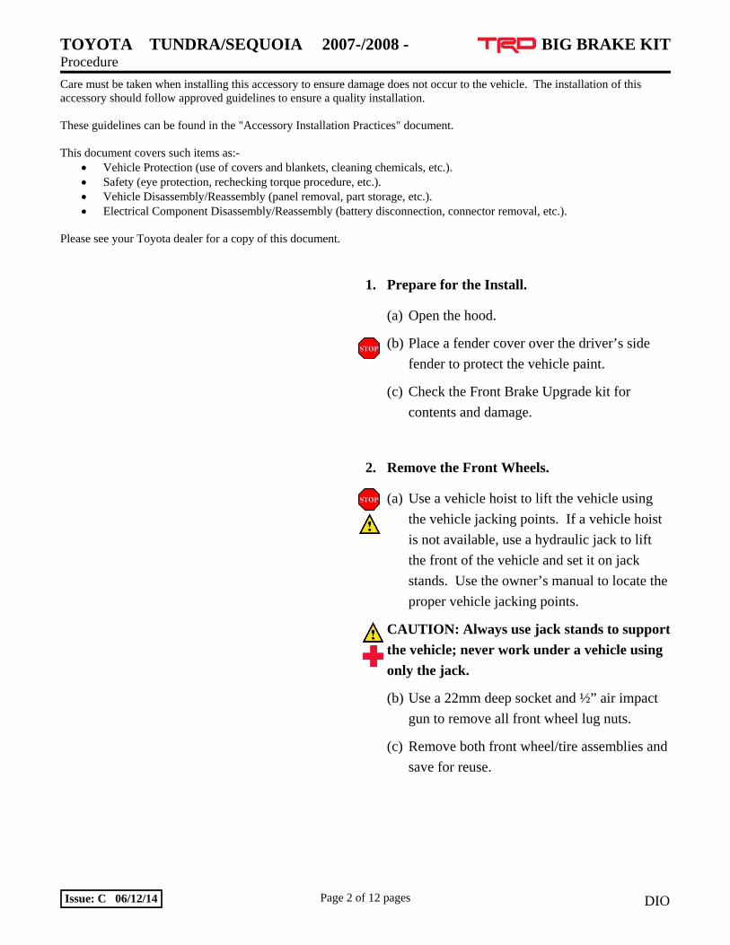
3. Disconnect & Remove the Front Brake Hose.
(a) Turn the steering wheel to the right to work
on the driver side; this allows easier access to
the brake hose. Turn the wheel to the left to
work on the passenger side.
(b) Place a drip tray directly below the inboard
brake line connection. This connection is
where the rubber hose attaches to the steel
brake line (Fig. 4-1).
CAUTION: Brake fluid will damage most
painted surfaces. Immediately clean any
spilled brake fluid from all painted surfaces.
(c) Do not remove the master cylinder fluid
reservoir cap yet. Leave it in place until the
new brake components are installed.
(d) Use a 10mm flare nut wrench to loosen the
steel line fitting where it attaches to the
rubber brake hose (Fig. 2-2).
(e) Use a pair of needle-nose pliers to remove
the brake line retaining clip (Fig. 2-3).
Retain this clip for re-use.
TOYOTA TUNDRA/SEQUOIA 2007-/2008 - BIG BRAKE KIT Procedure
Page 4 of 12 pages Issue: C 06/12/14 DIO
Fig. 2-4
Fig. 4-1
17mm Socket
Fig. 2-5
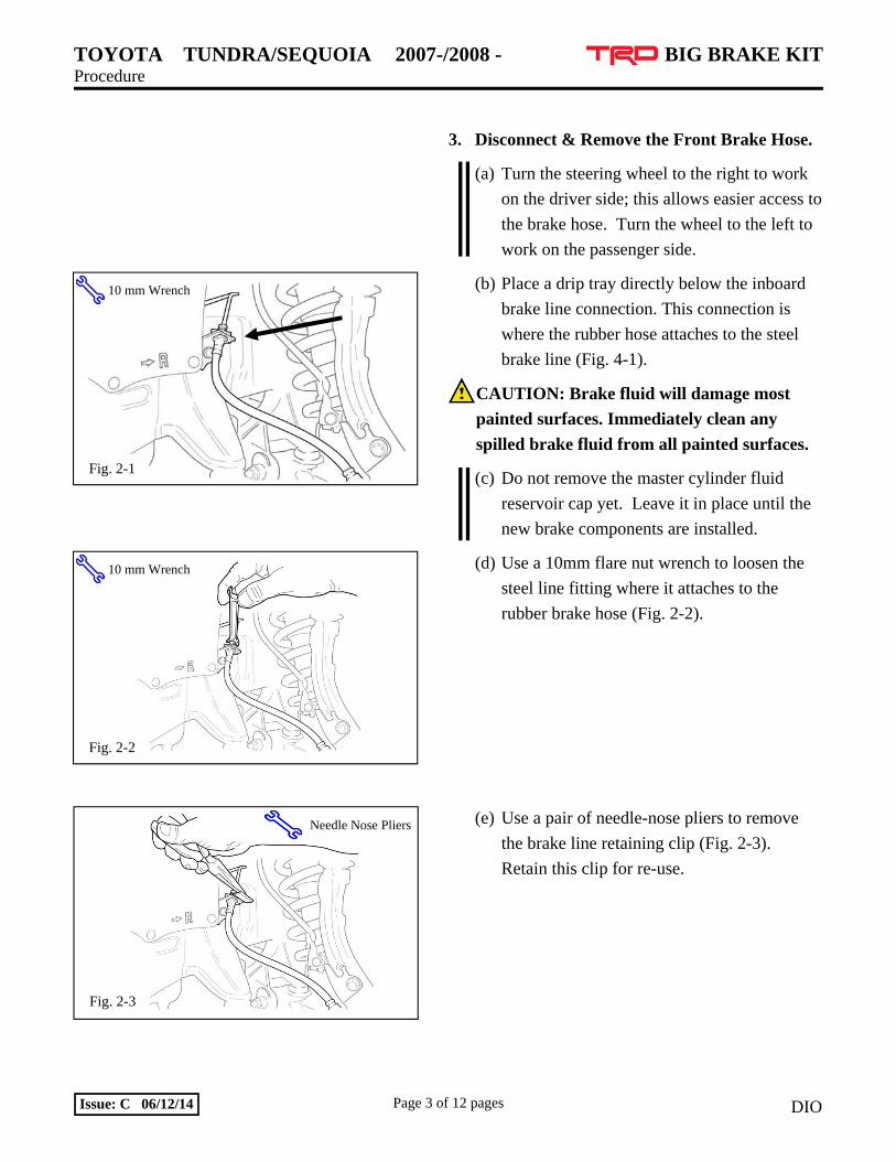
(f) Remove the rubber brake hose from the steel
line and place one of the supplied rubber
caps over the end of the steel line to stop
fluid loss (Fig. 2-4).
(g) Repeat Steps 2(d) through 2(f) for the
connection on the lower end of the rubber
brake hose (Fig. 2-5). Remove and discard
the rubber brake hose but retain the clip.
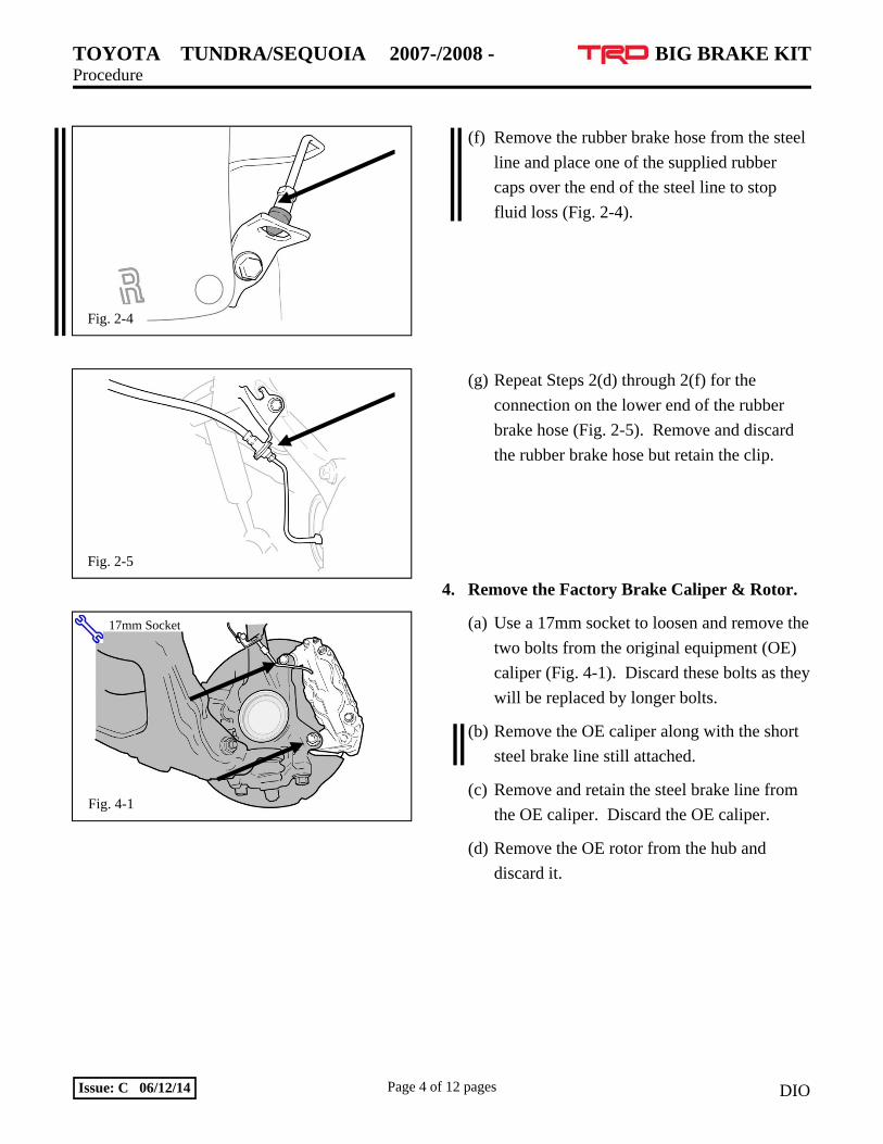
4. Remove the Factory Brake Caliper & Rotor.
(a) Use a 17mm socket to loosen and remove the
two bolts from the original equipment (OE)
caliper (Fig. 4-1). Discard these bolts as they
will be replaced by longer bolts.
(b) Remove the OE caliper along with the short
steel brake line still attached.
(c) Remove and retain the steel brake line from
the OE caliper. Discard the OE caliper.
(d) Remove the OE rotor from the hub and
discard it.

TOYOTA TUNDRA/SEQUOIA 2007-/2008 - BIG BRAKE KIT Procedure
Page 5 of 12 pages Issue: C 06/12/14 DIO
Fig. 5-2
Channel Lock Pliers
Fig. 5-1
Fig. 6-1
5. Modify the Rotor Dust Shield.
(a) The shaded areas of the flange on the dust
shield need to be bent back to allow for the
new larger TRD rotors (Fig. 5-1).
(b) Use a pair of channel lock pliers to carefully
bend the flange back on the OE dust shield
(Fig. 5-2).
6. Install the New Rotor.
(a) Install the appropriate rotor assembly, seating
it squarely on the hub face. Place two wheel
nuts on opposite studs (finger tight) to
prevent the rotor from falling off the hub
(Fig. 6-1).
CAUTION: The rotor hats have a small L
(left) or R (right) sticker. Install “L” on the
driver side and “R” on the passenger side.

TOYOTA TUNDRA/SEQUOIA 2007-/2008 - BIG BRAKE KIT Procedure
Page 6 of 12 pages Issue: C 06/12/14 DIO
Fig. 7-2
Discard OE
Bolts
Use new coarse thread TRD Bolts
Fig. 6-2
5mm Clearance
Bleed Screws Up
Fig. 7-1
17mm Socket & Torque Wrench
(b) Inspect the air gap to the dust shield; re-bend
this area of the dust shield if necessary. The
rotor and the dust shield need 5mm of
clearance (Fig. 6-2). Also, confirm the dust
shield does not contact the ball joint rubber
seals.
(c) Once the rotor is in place, remove the “L” or
“R” sticker and clean any adhesive residue.
NOTE: Air tool use is NOT allowed for re-
installation of any components.
7. Install the New Caliper.
(a) Remove the foam insert from between the
brake pads before installing the caliper.
(b) Install the appropriate caliper/pad assembly
onto the rotor with the bleed screws up and
fasten using the supplied M12x40mm bolts
(Fig. 7-1). Torque the bolts to 99 Nm (73 ft-
lbf) using a 17mm socket.
Torque: 99 Nm (73 ft-lbf)
CAUTION: The calipers have a small L (left)
or R (right) sticker. Install “L” on the driver
side and “R” on the passenger side.
CAUTION: As shown in Fig. 7-2, the new
bolts are longer than the OE bolts and have a
coarser thread pitch. DO NOT attempt to
reuse the OE bolts as they will destroy the
calipers.
(c) Once the caliper is in place, remove the “L”
or “R” sticker and clean any adhesive
residue.
TOYOTA TUNDRA/SEQUOIA 2007-/2008 - BIG BRAKE KIT Procedure
Page 7 of 12 pages Issue: C 06/12/14 DIO
Fig. 8-2
# 1 Disconnect# 3 Connect
# 2 Connect 10mm Socket
Fig. 8-3
10mm Socket 10mm Wrench
Fig. 8-1
# 1 Connect
# 2 Connect
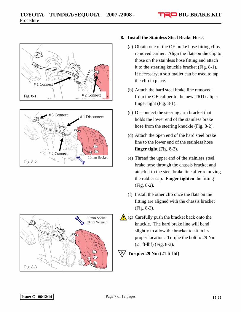
8. Install the Stainless Steel Brake Hose.
(a) Obtain one of the OE brake hose fitting clips
removed earlier. Align the flats on the clip to
those on the stainless hose fitting and attach
it to the steering knuckle bracket (Fig. 8-1).
If necessary, a soft mallet can be used to tap
the clip in place.
(b) Attach the hard steel brake line removed
from the OE caliper to the new TRD caliper
finger tight (Fig. 8-1).
(c) Disconnect the steering arm bracket that
holds the lower end of the stainless brake
hose from the steering knuckle (Fig. 8-2).
(d) Attach the open end of the hard steel brake
line to the lower end of the stainless hose
finger tight (Fig. 8-2).
(e) Thread the upper end of the stainless steel
brake hose through the chassis bracket and
attach it to the steel brake line after removing
the rubber cap. Finger tighten the fitting
(Fig. 8-2).
(f) Install the other clip once the flats on the
fitting are aligned with the chassis bracket
(Fig. 8-2).
(g) Carefully push the bracket back onto the
knuckle. The hard brake line will bend
slightly to allow the bracket to sit in its
proper location. Torque the bolt to 29 Nm
(21 ft-lbf) (Fig. 8-3).
Torque: 29 Nm (21 ft-lbf)
TOYOTA TUNDRA/SEQUOIA 2007-/2008 - BIG BRAKE KIT Procedure
Page 8 of 12 pages Issue: C 06/12/14 DIO
Fig. 9-1
(h) After centering the steering wheel, use a
10mm flare nut crow- foot socket and tighten
all three brake hose fittings to 15 Nm (11 ft-
lbf).
Torque: 15 Nm (11 ft-lbf)
Repeat Steps 3(a) through 8(h) for the
opposite side of the vehicle.
(i) Turn the steering knuckle while observing
the stainless steel brake hose for any binding.
Also confirm clearance to all suspension
components.
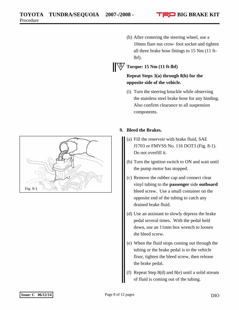
9. Bleed the Brakes.
(a) Fill the reservoir with brake fluid, SAE
J1703 or FMVSS No. 116 DOT3 (Fig. 8-1).
Do not overfill it.
(b) Turn the ignition switch to ON and wait until
the pump motor has stopped.
(c) Remove the rubber cap and connect clear
vinyl tubing to the passenger side outboard
bleed screw. Use a small container on the
opposite end of the tubing to catch any
drained brake fluid.
(d) Use an assistant to slowly depress the brake
pedal several times. With the pedal held
down, use an 11mm box wrench to loosen
the bleed screw.
(e) When the fluid stops coming out through the
tubing or the brake pedal is to the vehicle
floor, tighten the bleed screw, then release
the brake pedal.
(f) Repeat Step 8(d) and 8(e) until a solid stream
of fluid is coming out of the tubing.
TOYOTA TUNDRA/SEQUOIA 2007-/2008 - BIG BRAKE KIT Procedure
Page 9 of 12 pages Issue: C 06/12/14 DIO
Fig. 10-1
(g) Check the master cylinder reservoir and add
fluid if needed.
CAUTION: DO NOT allow the master
cylinder reservoir to run dry and draw in air.
(h) Connect the clear tubing to the passenger
side inboard bleed screw and repeat Steps
8(d) through 8(g).
(i) Connect the clear tubing to the driver side
outboard bleed screw and repeat Steps 8(d)
through 8(g).
(j) Lastly, connect the clear tubing to the driver
side inboard bleed screw and repeat Steps
8(d) through 8(g).
(k) After bleeding the front brake system, gently
tap the caliper body with a plastic mallet to
dislodge any small air bubbles and then
perform Steps 8(c) through 8(j) again.
(l) Tighten the bleeder screws to 11 Nm (8 ft-
lbf).
Torque: 11 Nm (8 ft-lbf)
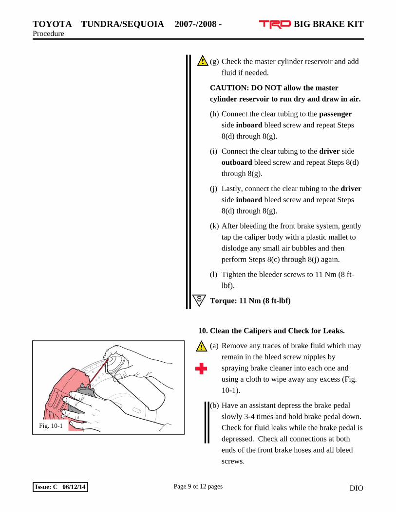
10. Clean the Calipers and Check for Leaks.
(a) Remove any traces of brake fluid which may
remain in the bleed screw nipples by
spraying brake cleaner into each one and
using a cloth to wipe away any excess (Fig.
10-1).
(b) Have an assistant depress the brake pedal
slowly 3-4 times and hold brake pedal down.
Check for fluid leaks while the brake pedal is
depressed. Check all connections at both
ends of the front brake hoses and all bleed
screws.
TOYOTA TUNDRA/SEQUOIA 2007-/2008 - BIG BRAKE KIT Procedure
Page 10 of 12 pages Issue: C 06/12/14 DIO
(c) Cover all 4 bleed screws with the attached
rubber caps.
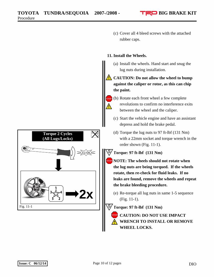
11. Install the Wheels.
(a) Install the wheels. Hand start and snug the
lug nuts during installation.
CAUTION: Do not allow the wheel to bump
against the caliper or rotor, as this can chip
the paint.
(b) Rotate each front wheel a few complete
revolutions to confirm no interference exits
between the wheel and the caliper.
(c) Start the vehicle engine and have an assistant
depress and hold the brake pedal.
(d) Torque the lug nuts to 97 ft-lbf (131 Nm)
with a 22mm socket and torque wrench in the
order shown (Fig. 11-1).
Torque: 97 ft-lbf (131 Nm)
NOTE: The wheels should not rotate when
the lug nuts are being torqued. If the wheels
rotate, then re-check for fluid leaks. If no
leaks are found, remove the wheels and repeat
the brake bleeding procedure.
(e) Re-torque all lug nuts in same 1-5 sequence
(Fig. 11-1).
Torque: 97 ft-lbf (131 Nm)
CAUTION: DO NOT USE IMPACT
WRENCH TO INSTALL OR REMOVE
WHEEL LOCKS.
Fig. 11-1
Torque 2 Cycles (All Lugs/Locks)
2x

TOYOTA TUNDRA/SEQUOIA 2007-/2008 - BIG BRAKE KIT Procedure
Page 11 of 12 pages Issue: C 06/12/14 DIO
Fig. 12-1
(f) Lower the vehicle from the lift or jack stands
and apply the brakes to ensure they are
functioning properly before driving the
vehicle.
12. Place the Warning Label and Documents in
the Vehicle.
(a) Place the break-in procedure tag on the inside
mirror and the owner’s document in the
glove box.
(b) Attach the spare tire warning label to the
vehicle lug wrench as shown (Fig. 12-1).
Replace the lug wrench in its storage bag and
replace the storage bag in its proper location.
(c) Carefully move vehicle at low speed and
apply brakes gently several times to ensure
that all components are working correctly.
WARNING: Do not apply the brakes
aggressively while driving until the rotors
have been properly bedded or broken-in.
Care and Maintenance
The brake calipers have a painted finish.
Immediately clean off any spilled brake fluid,
wiping it off with a soft, clean terry-cloth towel.
Bedding-in rotors and pads is critical to the
optimum performance of new brakes. When
bedding-in new parts, not only are the pads heat-
cycled, they are also depositing a layer of pad
material onto the rotor face. If they are not
bedded-in properly, an uneven layer of pad
material will be deposited onto the rotor, causing
vibration.
TOYOTA TUNDRA/SEQUOIA 2007-/2008 - BIG BRAKE KIT Procedure
Page 12 of 12 pages Issue: C 06/12/14 DIO
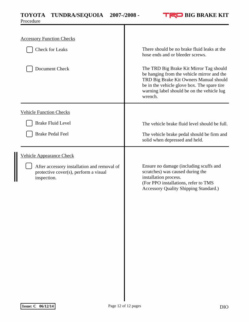
Accessory Function Checks
Check for Leaks
Document Check
Vehicle Function Checks
Brake Fluid Level
Brake Pedal Feel
Vehicle Appearance Check
After accessory installation and removal of protective cover(s), perform a visual inspection.
There should be no brake fluid leaks at the hose ends and or bleeder screws.
The TRD Big Brake Kit Mirror Tag should be hanging from the vehicle mirror and the TRD Big Brake Kit Owners Manual should be in the vehicle glove box. The spare tire warning label should be on the vehicle lug wrench.
The vehicle brake fluid level should be full.
The vehicle brake pedal should be firm and solid when depressed and held.
Ensure no damage (including scuffs and scratches) was caused during the installation process. (For PPO installations, refer to TMS Accessory Quality Shipping Standard.)