Part Number: 106586603 October 2005 McQuay Enfinity (R...
27
McQuay ® Enfinity ™ (R-410A) and Standard (R-22) Horizontal Water Source Heat Pumps Unit Sizes 007 – 070 / R-22 Refrigerant Unit Sizes 019 – 060 / R-410A Refrigerant Contents Model Nomenclature . . . . . . . . . . . . . . . . . . . . . . . . . . 2 Transportation & Storage . . . . . . . . . . . . . . . . . . . . . . . 2 Installation . . . . . . . . . . . . . . . . . . . . . . . . . . . . . . . . 2-4 Electrical Data . . . . . . . . . . . . . . . . . . . . . . . . . . . . . . . 5 Piping . . . . . . . . . . . . . . . . . . . . . . . . . . . . . . . . . . . . . 5 Cleaning & Flushing System . . . . . . . . . . . . . . . . . . . . 6 Start-up . . . . . . . . . . . . . . . . . . . . . . . . . . . . . . . . . . . . 7 Operating Limits . . . . . . . . . . . . . . . . . . . . . . . . . . . . . 8 Typical Wiring Diagrams . . . . . . . . . . . . . . . . . . . . . 9-11 Unit Operation . . . . . . . . . . . . . . . . . . . . . . . . . . . 12-14 Thermostat Connections. . . . . . . . . . . . . . . . . . . . 16-17 Options for Mark IV/AC Units . . . . . . . . . . . . . . . . 18-19 Field Installed Options on MicroTech Units . . . . . . . . 20 Sequence of Operation . . . . . . . . . . . . . . . . . . . . . . . 21 Troubleshooting WSHP. . . . . . . . . . . . . . . . . . . . . 22-24 Troubleshooting Refrigeration Circuit . . . . . . . . . . . . . 24 General Maintenance . . . . . . . . . . . . . . . . . . . . . . . . . 25 Typical Refrigeration Cycles . . . . . . . . . . . . . . . . . . . . 26 Installation & Maintenance Data Group: WSHP Part Number: 106586603 Date: October 2005 IM 742-2 ©2005 McQuay International ®
Transcript of Part Number: 106586603 October 2005 McQuay Enfinity (R...
McQuay® Enfinity™ (R-410A) and Standard (R-22)Horizontal Water Source Heat PumpsUnit Sizes 007 – 070 / R-22 RefrigerantUnit Sizes 019 – 060 / R-410A Refrigerant
ContentsModel Nomenclature . . . . . . . . . . . . . . . . . . . . . . . . . . 2Transportation & Storage . . . . . . . . . . . . . . . . . . . . . . . 2Installation . . . . . . . . . . . . . . . . . . . . . . . . . . . . . . . . 2-4Electrical Data . . . . . . . . . . . . . . . . . . . . . . . . . . . . . . . 5Piping . . . . . . . . . . . . . . . . . . . . . . . . . . . . . . . . . . . . . 5Cleaning & Flushing System . . . . . . . . . . . . . . . . . . . . 6Start-up. . . . . . . . . . . . . . . . . . . . . . . . . . . . . . . . . . . . 7Operating Limits . . . . . . . . . . . . . . . . . . . . . . . . . . . . . 8Typical Wiring Diagrams . . . . . . . . . . . . . . . . . . . . . 9-11
Unit Operation . . . . . . . . . . . . . . . . . . . . . . . . . . . 12-14Thermostat Connections. . . . . . . . . . . . . . . . . . . . 16-17Options for Mark IV/AC Units . . . . . . . . . . . . . . . . 18-19Field Installed Options on MicroTech Units . . . . . . . . 20Sequence of Operation . . . . . . . . . . . . . . . . . . . . . . . 21Troubleshooting WSHP. . . . . . . . . . . . . . . . . . . . . 22-24Troubleshooting Refrigeration Circuit . . . . . . . . . . . . . 24General Maintenance. . . . . . . . . . . . . . . . . . . . . . . . . 25Typical Refrigeration Cycles . . . . . . . . . . . . . . . . . . . . 26
Installation & Maintenance Data
Group: WSHP
Part Number: 106586603
Date: October 2005
IM 742-2
©2005 McQuay International
®
Note: Installation and maintenance are to be performed only by qualified personnel who are familiar with local codesand regulations, and are experienced with this type of equipment. Caution: Sharp edges are a potential injury hazard.Avoid contact with them.
Page 2 / IM 742
Transportation & Storage
InstallationGeneral
Upon receipt of the equipment, check carton for visibledamage. Make a notation on the shipper’s delivery ticketbefore signing. If there is any evidence of rough handling,immediately open the cartons to check for concealed dam-age. If any damage is found, notify the carrier within 48hours to establish your claim and request their inspectionand a report. The Warranty Claims Department should thenbe contacted.
Do not stand or transport the machines on end. For stor-ing, each carton is marked with “up” arrows.
In the event that elevator transfer makes up-ended posi-tioning unavoidable, absolutely ensure that the machine isin the normal upright position for at least 24 hours beforeoperating.
Temporary storage at the job site must be indoors, com-pletely sheltered from rain, snow, etc. High or low tempera-tures naturally associated with weather patterns will notharm the conditioners. Excessively high temperatures,140°F (60°C) and higher, may deteriorate certain plasticmaterials and cause permanent damage.
1. To prevent damage, this equipment should not be oper-ated for supplementary heating and cooling during theconstruction period.
2. Inspect the carton for any specific tagging numbersindicated by the factory per a request from the installingcontractor. At this time the voltage, phase and capaci-ty should be checked against the plans.
3. Check the unit size against the plans to ensure unitinstallation is in the correct location.
4. After removing the carton, remove the hanger kit fromthe fan housing.
5. Before installation, check the available ceiling heightversus the height of the unit.
6. Note the location and routing of water piping, conden-sate drain piping, and electrical wiring. The locations ofthese items are clearly marked on submittal drawings.
7. The installing contractor will find it beneficial to conferwith piping, sheet metal, ceiling and electrical foremenbefore installing any conditioners.
NOTE: Check the unit name plate for correct voltage withthe plans before installing the equipment. Also,make sure all electrical ground connections aremade in accordance with local code.
8. Remove all shipping blocks in the fan wheel.
9. Change the airflow direction from straight discharge toend discharge or vice versa before the unit is installedin the ceiling. Refer to the section in this bulletin forinstructions.
10. We recommend that the contractor cover the condi-tioners with plastic film to protect the machines duringfinishing of the building. This is critical while sprayingfireproofing material on bar joists, sandblasting, spraypainting and plastering. If plastic film is not available,the shipping carton may be modified to cover the unitsduring construction.
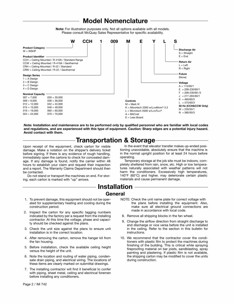
Model Nomenclature
Product CatagoryW = WSHP
Product IdentifierCCH = Ceiling Mounted / R-410A / Standard RangeCCW = Ceiling Mounted / R-410A / GeothermalCRH = Ceiling Mounted / R-22 / StandardCRW = Ceiling Mounted / R-22 / Geothermal
Design Series1 = A Design2 = B Design3 = C Design4 = D Design
Nominal Capacity007 = 7,000 030 = 30,000009 = 9,000 036 = 36,000012 = 12,000 042 = 42,000015 = 15,000 048 = 48,000019 = 19,000 060 = 60,000024 = 24,000 070 = 70,000
W CCH 1 009 M E Y L S
Discharge AirS = StraightE = End
Return AirL = LeftR = Right
Future(None)
VoltageA = 115/60/1E = 208-230/60/1F = 208-230/60-/3J = 277-265/60/1K = 460/60/3L = 575/60/350 Hz (CCH&CCW Only)M = 230/50/1N = 380/50/3
Note: For illustration purposes only. Not all options available with all models.Please consult McQuay Sales Representative for specific availability.
ControlsM = Mark IVK = Micortech 2000 w/LONMARK® 3.3L = Microtech 2000 w/LONTALK®
A = BACnetE = Less Board
IM 742 / Page 3
Unit Location
1. Locate the unit in an area that allows for easy removal ofthe filter and access panels. Leave a minimum of 18” ofclearance around the heat pump for easy removal, andto perform routine maintenance, or troubleshooting.Provide sufficient room to make water, electrical andduct connections.
2. The contractor should make sure that adequate ceilingpanel access exists, including clearance for hangerbrackets, duct collars and fittings at water and electricalconnections.
3. Allow adequate room below the unit for a condensatetrap and do not locate the unit above pipes.
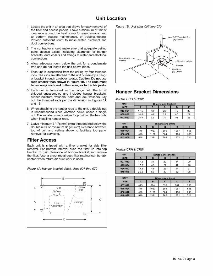
4. Each unit is suspended from the ceiling by four threadedrods. The rods are attached to the unit corners by a hang-er bracket through a rubber isolator. Caution: Do not userods smaller than shown in Figure 1B. The rods mustbe securely anchored to the ceiling or to the bar joists.
5. Each unit is furnished with a hanger kit. The kit isshipped unassembled and includes hanger brackets,rubber isolators, washers, bolts and lock washers. Layout the threaded rods per the dimension in Figures 1Aand 1B.
6. When attaching the hanger rods to the unit, a double nutis recommended since vibration could loosen a singlenut. The installer is responsible for providing the hex nutswhen installing hanger rods.
7. Leave minimum 3" (76 mm) extra threaded rod below thedouble nuts or minimum 3" (76 mm) clearance betweentop of unit and ceiling above to facilitate top panelremoval for servicing.
Figure 1B. Unit sizes 007 thru 070
3/8" Threaded Rod(By Others)
Vibration Isolator
Washer
Hex Nuts(By Others)
Bolt & LockWasher
Filter AccessEach unit is shipped with a filter bracket for side filterremoval. For bottom removal push the filter up into topbracket to gain clearance of bottom bracket and removethe filter. Also, a sheet metal duct filter retainer can be fab-ricated when return air duct work is used.
Figure 1A. Hanger bracket detail, sizes 007 thru 070
B
CoilAirflow
E C
D
Comp
ControlBox
FanAssembly
A
Models CCH & CCWUNIT
SIZE A B C D E
019-024 17.5 42 22 42 20
030-036 18.5 46 23 46 21042-060 25.5 52 30 52 28
Dimensions (Inches)
Hanger Bracket Dimensions
UNIT
SIZE A B C D E
019-024 445 1067 559 1067 508
030-036 470 1168 584 1168 533042-060 648 1321 762 1321 711
Dimensions (mm)
Models CRH & CRW
UNIT
SIZE A B C D E
007-012 17.5 34 22 34 20
015-024 17.5 42 22 42 20
030-042 18.5 46 23 46 21048-070 25.5 52 30 52 28
Dimensions (Inches)
UNIT
SIZE A B C D E
007-012 445 864 559 864 508
015-024 445 1067 559 1067 508
030-042 470 1168 584 1168 533048-070 648 1321 762 1321 711
Dimensions (mm)

Page 4 / IM 742
Air Discharge ConversionUnit sizes 007 thru 070 can be shipped as straight dis-charge air or end discharge air arrangement. In the eventthat the unit needs to be converted from straight dischargeto end discharge:
1. Remove top panel.
2. Remove the access panel to the fan motor. Remove thepiece of insulation at the bottom on the side of the bot-tom panel.
3. Remove the fan discharge panel, rotate it 180 degrees,and move it to the other side. In other words, with
straight air discharge the housing is bottom horizontaland with an end discharge the housing is top horizontal.
4. Remove the three bolts holding the fan motor on androtate it so that the motor oilers are in the up position.
5. Install insulation base panel below new access panellocation.
6. Reinstall the top panel.
7. Reinstall the piece of insulation and the access panel.
Ductwork & AttenuationDischarge ductwork is normally used with these condition-ers. Return air ductwork may also be required.
All ductwork should conform to industry standards ofgood practice as described in the ASHRAE Systems Guide.
The discharge duct system will normally consist of aflexible connector at the unit, a transition piece to the fullduct size, a short run of duct, an elbow without vanes, anda trunk duct teeing into a branch duct with discharge dif-fusers as shown in Figure 2. The transition piece must nothave angles totaling more than 30° or severe loss of air per-formance can result. Do not connect the full duct size to theunit without using a transition piece down to the size of thedischarge collar on the unit. With metal duct material, thesides only of the elbow and entire branch duct should beinternally lined with acoustic fibrous insulation for soundattenuation. Glass fiber duct board material is more absorb-ing and may permit omission of the canvas connector.
The ductwork should be laid out so that there is no lineof sight between the conditioner discharge and the distrib-
ution diffusers.Return air ducts can be brought in through a low side
wall filter-grille and then up through the stud pieces to aceiling plenum or through air ceiling filter-grilles. The ceilingfilter-grille must not be placed directly under the condition-er.
Return air ductwork can be connected to the standardfilter rack. See Figure 3 (side filter removal shown). The fil-ter rack can be installed for bottom filter removal or side fil-ter removal by locating the brackets. For side filter removalthe brackets should be located on the bottom, left side, andtop. For bottom filter removal the brackets should bemounted on the left side top and right side with the springclips supporting the filter.
Do not use sheet metal screws directly into the unit cab-inet for connection of supply or return air ductwork, espe-cially return air ductwork which can hit the drain pan or theair coil.
Figure 2. Suggested duct layout Figure 3. Filter rack/return air duct collar
2x2 Ft.Diffuser(ExampleOnly)
Branch DuctInternally LinedWith AcousticFibrousInsulation
Trunk Duct
Square Elbow
CanvasCollar
HeatPump
TransformationPiece
Discharge CollarOn Heat Pump
Both Sides Internally Lined WithAcoustic Fibrous Glass Insulation
Suggested Duct Layout ForMultiple Diffuser Application
Standard 1" (25mm)
Optional 2" (51 mm) Rackalso available.
Ventilation may require outside air. The temperature of theventilation air must be controlled so that mixture of outsideair and return air entering the conditioner does not exceedconditioner application limits. It is also typical to close offthe ventilation air system during unoccupied periods (nightsetback).
The ventilation air system is generally a separate build-
Ventilation Airing subsystem with distribution ductwork. Simple introduc-tion of the outside air into each return air plenum chamberreasonably close to the conditioner air inlet is recommend-ed. Do not duct outside air directly to the conditioner inlet.Provide sufficient distance for thorough mixing of outsideand return air. See Operating Limits on page 8.

IM 742 / Page 5
Electrical Data
1. Verify the compatibility between the voltage and phaseof the available power and that shown on the unit serialplate. Line and low voltage wiring must comply with localcodes or the National Electrical Code, whicheverapplies.
2. Apply correct line voltage to the unit. A 7⁄8" (22mm) holeand/or a 11⁄8" (29 mm) knockout is supplied on the sideof the unit. A disconnect switch near the unit is requiredby code. Power to the unit must be sized correctly andhave dual element (Class RK5) fuses or an HACR circuit
Generalbreaker for branch circuit overcurrent protection. See thenameplate for correct ratings.
3. Three phase 50 cycle units, 380/50/3, require a neutralwire for 230/50/1 power to the fan circuit.
4. Connect the thermostat/subbase wiring with the power“off ” to the unit.
5. Field supplied relays installed on the input terminalsW1, W2, Y1, Y2 or G may introduce electrical noise.Never install relay coils in series with the inputs.
230 Volt Operation
Fan Assembly
All 208-230 volt single-phase and three-phase units are fac-tory wired for 208 volt operation. For 230 phase operation,the line voltage tap on the 24 volt transformer must be
All fan motors are multi-speed, PSC type with integralmounting brackets and thermal overload protection. Themotor is isolated from the fan housing for minimum vibra-tion transmission. Fan motors on 019 thru 070 have a ter-minal strip on the motor body for simple motor speedchange without going back to the control box. To changefan motor speed to high on size 015 through 048, inter-change the red wire with the black wire. For low speed,sizes 012, 024, 030, 036, 042, 060 and 070, interchange the
black wire with the red wire. All the fan/motor assemblieshave a removable orifice ring on the housing to accommo-date motor and fan wheel removal without disconnectingthe ductwork. The fan housing protrudes through the cabi-net allowing adequate material for connection of flexibleduct. Each model unit is shipped from the factory for maxi-mum performance and minimum sound requirements. Fansound levels and performance can be affected by externalstatic pressure.
changed. Disconnect and cap the red lead wire and inter-change it with the orange lead wire on the primary of the 24volt transformer.
Piping1. All units should be connected to supply and return pip-
ing in a two-pipe reverse return configuration. Areverse return system is inherently self-balancing andrequires only trim balancing where multiple quantitiesof units with different flow and pressure drop charac-teristics exist in the same loop. Check for proper waterbalance by measuring differential temperature readingacross the water connections. To insure proper waterflow, the differential flow should be 10°F to 14°F (5°C to8°C) for units in cooling mode.
A direct return system may also work acceptably,but proper water flow balancing is more difficult toachieve and maintain.
2. The piping can be steel, copper or PVC.
3. Supply and return runouts usually join the unit via shortlengths of high pressure flexible hose which are soundattenuators for both unit operating noise and hydraulicpumping noise. One end of the hose should have aswivel fitting to facilitate removal for service. Hard pip-ing can also be brought directly to the unit. This optionis not recommended since no vibration or noise atten-uation can be accomplished. The hard piping musthave unions to facilitate unit removal. See Figure 5 fortypical piping setup.
4. Some flexible hose threaded fittings are supplied withsealant compound. If not, apply Teflon tape to assure atight seal.
5. Supply and return shutoff valves are required at eachconditioner. The return valve is used for balancing andshould have a “memory stop” so that it can always beclosed off but can only be reopened to the proper posi-tion for the flow required.
6. No unit should be connected to the supply and returnpiping until the water system has been cleaned andflushed completely. After the cleaning and flushing hastaken place, the initial connection should have allvalves wide open in preparation for water system flush-ing.
7. Condensate piping can be steel, copper or PVC. Eachunit includes a condensate connection.
8. The condensate disposal piping must be trapped. Thepiping must be pitched away from the unit not less than1⁄4" per foot. The unit has a 3/4 inch female pipe fittingon each water source heat pump to accommodate thecondense drain connection. Factory supplied conden-sate hose assemblies have a pipe thread fitting to facil-itate connection of a flexible vinyl or steel braided hose.
Figure 4. CRH & CRW Sizes 007 thru 012 (Factory Wired)Figure 4a. CCH, CCW, CRH & CRW Sizes 015 thru 070(Factory Wired)
FANMOTOR
FANMOTOR
WHITE (COMMON)
BROWN (CAPACITOR)
BLACK (HIGH SPEED) SIZES 007, 009, 012
RED (LOW SPEED) Recommended for useon size 012 only
WHITE (COMMON)
BROWN (CAPACITOR)
BLACK (HIGH SPEED) SIZES 019 (R-22only), 024, 030, 036, 042, 060, 070
RED (LOW SPEED)SIZES - 015. 019 (R-410A only), 048
Sizes 015 & 070 available as CRH or CRW only
Page 6 / IM 742
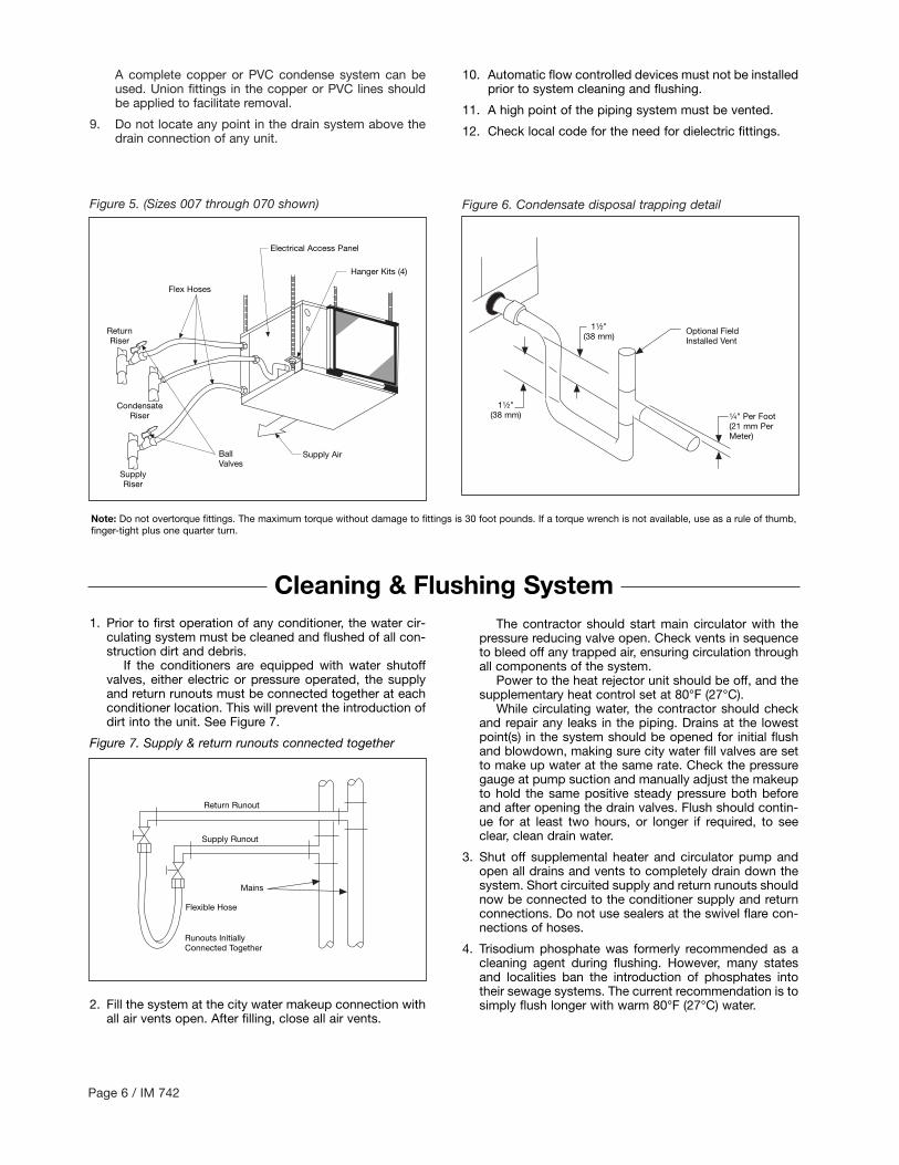
A complete copper or PVC condense system can beused. Union fittings in the copper or PVC lines shouldbe applied to facilitate removal.
9. Do not locate any point in the drain system above thedrain connection of any unit.
Figure 5. (Sizes 007 through 070 shown) Figure 6. Condensate disposal trapping detail
BallValves
SupplyRiser
ReturnRiser
CondensateRiser
Supply Air
Optional FieldInstalled Vent
11⁄2"(38 mm)
11⁄2"(38 mm)
Hanger Kits (4)
Flex Hoses
Electrical Access Panel
1⁄4" Per Foot(21 mm PerMeter)
10. Automatic flow controlled devices must not be installedprior to system cleaning and flushing.
11. A high point of the piping system must be vented.
12. Check local code for the need for dielectric fittings.
Cleaning & Flushing System1. Prior to first operation of any conditioner, the water cir-
culating system must be cleaned and flushed of all con-struction dirt and debris.
If the conditioners are equipped with water shutoffvalves, either electric or pressure operated, the supplyand return runouts must be connected together at eachconditioner location. This will prevent the introduction ofdirt into the unit. See Figure 7.
Figure 7. Supply & return runouts connected together
2. Fill the system at the city water makeup connection withall air vents open. After filling, close all air vents.
The contractor should start main circulator with thepressure reducing valve open. Check vents in sequenceto bleed off any trapped air, ensuring circulation throughall components of the system.
Power to the heat rejector unit should be off, and thesupplementary heat control set at 80°F (27°C).
While circulating water, the contractor should checkand repair any leaks in the piping. Drains at the lowestpoint(s) in the system should be opened for initial flushand blowdown, making sure city water fill valves are setto make up water at the same rate. Check the pressuregauge at pump suction and manually adjust the makeupto hold the same positive steady pressure both beforeand after opening the drain valves. Flush should contin-ue for at least two hours, or longer if required, to seeclear, clean drain water.
3. Shut off supplemental heater and circulator pump andopen all drains and vents to completely drain down thesystem. Short circuited supply and return runouts shouldnow be connected to the conditioner supply and returnconnections. Do not use sealers at the swivel flare con-nections of hoses.
4. Trisodium phosphate was formerly recommended as acleaning agent during flushing. However, many statesand localities ban the introduction of phosphates intotheir sewage systems. The current recommendation is tosimply flush longer with warm 80°F (27°C) water.
Return Runout
Supply Runout
Mains
Flexible Hose
Runouts InitiallyConnected Together
Note: Do not overtorque fittings. The maximum torque without damage to fittings is 30 foot pounds. If a torque wrench is not available, use as a rule of thumb,finger-tight plus one quarter turn.

IM 742 / Page 7
Start-up1. Open all valves to full open position and turn on power
to the conditioner.
2. Set thermostat for “Fan Only” operation by selecting“Off” at the system switch and “On” at the fan switch.If “Auto” fan operation is selected, the fan will cyclewith the compressor. Check for proper air delivery.
3. For those units that have two-speed motors, reconnectfor low speed operation if necessary.
4. Set thermostat to “Cool.” If the thermostat is an auto-matic changeover type, simply set the cooling temper-ature to the coolest position. On manual changeovertypes additionally select “Cool” at the systemswitch.
Again, many conditioners have time delays whichprotect the compressor(s) against short cycling. After afew minutes of operation, check the discharge grillesfor cool air delivery. Measure the temperature differ-ence between entering and leaving water. It should beapproximately 11⁄2 times greater than the heating modetemperature difference. For example, if the coolingtemperature difference is 15°F (8°C), the heating tem-perature difference should have been 10°F (5°C).Without automatic flow control valves, target a coolingtemperature difference of 10°F to 14°F (5°C to 8°C).Adjust the combination shutoff/balancing valve in thereturn line to a water flow rate which will result in the10˚F to 14°F (5°C to 8°C) difference.
5. Set thermostat to “Heat.” If the thermostat is the auto-matic changeover type, set system switch to the“Auto” position and depress the heat setting to thewarmest selection. Some conditioners have built-intime delays which prevent the compressor from imme-diately starting. With most control schemes, the fan willstart immediately. After a few minutes of compressor
operation, check for warm air delivery at dischargegrille. If this is a “cold building” start-up, leave unit run-ning until return air to the unit is at least 65°F (18°C).
Measure the temperature difference between enter-ing and leaving air and entering and leaving water. Withentering water of 60°F to 80°F (16°C to 27°C), leavingwater should be 6°F to 12°F (3.3°C to 6.6°C) cooler,and the air temperature rise through the machineshould not exceed 35°F (19°C). If the air temperatureexceeds 35°F (19°C), then the water flow rate is inade-quate.
6. Check the elevation and cleanliness of the condensateline. If the air is too dry for sufficient dehumidification,slowly pour enough water into the condensate pan toensure proper drainage.
7. If the conditioner does not operate, check the followingpoints:a. Is supply voltage to the machine compatible?b. Is thermostat type appropriate?c. Is thermostat wiring correct?
8. If the conditioner operates but stops after a brief period:a. Is there proper airflow? Check for dirty filter, incor-
rect fan rotation (3-phase fan motors only), or incor-rect ductwork.
b. Is there proper water flow rate within temperaturelimits? Check water balancing; backflush unit if dirt-clogged.
9. Check for vibrating refrigerant piping, fan wheels, etc.
10. Do not lubricate the fan motor during the first year ofoperation as it is prelubricated at the factory.
11. Field supplied relays installed on the input terminalsW1, W2, Y1, Y2 or G may introduce electrical noise.Never install relay coils in series with the inputs.
5. Refill the system with clean water. Test the water usinglitmus paper for acidity, and treat as required to leave thewater slightly alkaline (pH 7.5 to 8.5). The specified per-centage of antifreeze may also be added at this time.Use commercial grade antifreeze designed for HVACsystems only. Do not use automotive grade antifreeze.
Once the system has been filled with clean water andantifreeze (if used), precautions should be taken to pro-tect the system from dirty water conditions. Dirty waterwill result in system wide degradation of performanceand solids may clog valves, strainers, flow regulators,etc. Additionally, the heat exchanger may becomeclogged which reduces compressor service life or caus-es premature failure.
6. Set the loop water controller heat add setpoint to 70°F(21°C) and the heat rejection setpoint to 85°F (29°C).Supply power to all motors and start the circulatingpumps. After full flow has been established through allcomponents including the heat rejector (regardless ofseason) and air vented and loop temperatures stabilized,each of the conditioners will be ready for check, test andstart-up, air balancing, and water balancing.
Page 8 / IM 742
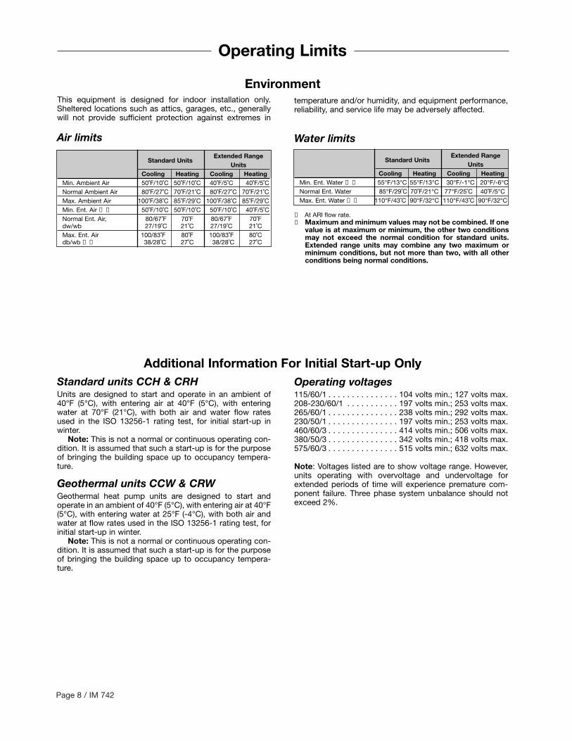
Operating Limits
Extended RangeStandard Units
UnitsCooling Heating Cooling Heating
Min. Ambient Air 50˚F/10˚C 50˚F/10˚C 40˚F/5˚C 40˚F/5˚C Normal Ambient Air 80˚F/27˚C 70˚F/21˚C 80˚F/27˚C 70˚F/21˚CMax. Ambient Air 100˚F/38˚C 85˚F/29˚C 100˚F/38˚C 85˚F/29˚CMin. Ent. Air ➀ ➁ 50˚F/10˚C 50˚F/10˚C 50˚F/10˚C 40˚F/5˚CNormal Ent. Air, 80/67˚F 70˚F 80/67˚F 70˚Fdw/wb 27/19˚C 21˚C 27/19˚C 21˚CMax. Ent. Air 100/83˚F 80˚F 100/83˚F 80˚Cdb/wb ➀ ➁ 38/28˚C 27˚C 38/28˚C 27˚C
➀ At ARI flow rate.➁ Maximum and minimum values may not be combined. If one
value is at maximum or minimum, the other two conditionsmay not exceed the normal condition for standard units.Extended range units may combine any two maximum orminimum conditions, but not more than two, with all otherconditions being normal conditions.
This equipment is designed for indoor installation only.Sheltered locations such as attics, garages, etc., generallywill not provide sufficient protection against extremes in
Environment
Standard units CCH & CRHUnits are designed to start and operate in an ambient of40°F (5°C), with entering air at 40°F (5°C), with enteringwater at 70°F (21°C), with both air and water flow ratesused in the ISO 13256-1 rating test, for initial start-up inwinter.
Note: This is not a normal or continuous operating con-dition. It is assumed that such a start-up is for the purposeof bringing the building space up to occupancy tempera-ture.
Geothermal units CCW & CRWGeothermal heat pump units are designed to start andoperate in an ambient of 40°F (5°C), with entering air at 40°F(5°C), with entering water at 25°F (-4°C), with both air andwater at flow rates used in the ISO 13256-1 rating test, forinitial start-up in winter.
Note: This is not a normal or continuous operating con-dition. It is assumed that such a start-up is for the purposeof bringing the building space up to occupancy tempera-ture.
temperature and/or humidity, and equipment performance,reliability, and service life may be adversely affected.
Air limits Water limitsExtended Range
Standard UnitsUnits
Cooling Heating Cooling HeatingMin. Ent. Water ➀ ➁ 55°F/13°C 55°F/13°C 30°F/-1°C 20°F/-6°CNormal Ent. Water 85°F/29˚C 70˚F/21°C 77°F/25˚C 40˚F/5°CMax. Ent. Water ➀ ➁ 110°F/43˚C 90°F/32°C 110°F/43˚C 90°F/32°C
Additional Information For Initial Start-up OnlyOperating voltages115/60/1 . . . . . . . . . . . . . . . 104 volts min.; 127 volts max.208-230/60/1 . . . . . . . . . . . 197 volts min.; 253 volts max.265/60/1 . . . . . . . . . . . . . . . 238 volts min.; 292 volts max.230/50/1 . . . . . . . . . . . . . . . 197 volts min.; 253 volts max.460/60/3 . . . . . . . . . . . . . . . 414 volts min.; 506 volts max.380/50/3 . . . . . . . . . . . . . . . 342 volts min.; 418 volts max.575/60/3 . . . . . . . . . . . . . . . 515 volts min.; 632 volts max.
Note: Voltages listed are to show voltage range. However,units operating with overvoltage and undervoltage forextended periods of time will experience premature com-ponent failure. Three phase system unbalance should notexceed 2%.

FanMotor
070 - Blk060 - Blk048 - Red042 - Blk036 - Blk030 - Blk
ComprMotor
CC - Compressor ContactorHTR - Crankcase Heater (Optional)CAP - Motor Capacitor
CondensateSensor
Common
Fan
L1 Com
pressor
Reversing ValveSolenoid (24 VAC) 0 W
2G W
1Y1 F E L U A P V R C
Mark IVPC
Board
Hi Pressure
Lo Pressure
Lo Temp
GroundL1 L2
CC
Heater
IM 742 / Page 9
Typical Wiring Diagrams
Notes:
1. Unit is factory wired for 208V operation. If 230Vpower supply is used, transformer must berewired by disconnecting the power lead from thered transformer primary wire and connecting thepower lead to the orange transformer primarywire. Place an insulation cap on the red trans-former primary wire.
2. All temperature and pressure switches are nor-mally closed.
3. Component layout shown below is typical. Somecomponents may not be used on this model orvoltage.
4. Mark IV/AC controller board contains a static sen-sitive microprocessor. Proper grounding of fieldservice personnel should be observed or damageto controller may result.
5. Terminal block on Mark IV/AC board provides 24VAC at terminals R and C. All other outputs are 24VDC.
6. Field supplied relays installed on the input ter-minals (W1, W2, Y1 or G) may interfere withproper unit operation. Never install relay coilsin series with inputs.
7. For more information pertaining to the Mark IV/ACcontroller, refer to OM120.
Figure 8. Typical Mark IV/AC wiring diagram
COMPONENT LAYOUT➀ COMPRESSOR CONTACTOR➁ FAN CONTACTOR➂ TRANSFORMER➃ PC BOARD➄ AUXILIARY RELAY➅ CIRCUIT BREAKER

Page 10 / IM 742
Compr
T1
RDRD
75460 & 575V
Only
10
18
BK23RD 208V
BK/RD 460VBK 575V
OR 240V
52
YE
51Lo Press
Lo Temp
Hi PressRV
Solenoid
2938
23Fan Relay
BR
BR
3031
2932
3334
36
37
MicroTechController
3528
27
26
2524
J4 14 1213 11 910 8 67 5 34 12 1011
69 E
L
U
P
C73
73
J212
12121212121212
62
63
64
65
Terminal Board #11st Option
(Factory InstalledSee Note 3)
66
67
6874
75
76
5
43
2
1
1110987654321J1
Dis
char
ge A
ir In
Dis
char
ge A
ir C
om
Wat
er O
ut In
Wat
er O
ut C
om
Aux
Mod
ule
DC
+
Aux
Mod
ule
DC
Com
Aux
Mod
ule
SE
L 1
Aux
Mod
ule
SE
L 2
Aux
Mod
ule
CLK
Aux
Mod
ule
XM
T
Aux
Mod
ule
RC
V
Lo T
emp
SR
C
Con
den
sate
Lo P
ress
SIG
Lo T
emp
SIG
Lo P
ress
SR
C
RV
Com
Hi P
ress
SIG
Com
p C
om
RV
Out
Fan
Com
Com
p O
ut
Fan
Out
Rem
ote
DI S
RC
Rem
ote
DI S
IG
Sp
are
Rel
ay N
C
Sp
are
Rel
ay C
om
Sp
are
Rel
ay N
O
RM
Sen
sor
LED
Tena
nt O
verr
ide
RM
Sen
sor
In
RM
Sen
sor
Com
Lon
Talk
Lon
Talk
24VA
C C
om
24V
Gnd
24VA
C
70
71 (See Note 3)
72 (See Note 3)
J5 89 67 45 3 1 J62
37
36
22
23
35
Fan Relay460 & 575V Only
FanMotor
575V Only
34
1 2 3 4 5
22
1920
21
Cap
A B7
5
1 2 3
CondensateOverflow
24VAC
Line
BK
32
ComprContr
DischargeAir
19
20
RDYE
21
YE
WH
RD
GN
BL
OR
BK
56
5554
53
WaterOut
BR
FanMotor
Cap
22
BK
213
4
52
51
J2
J1
1
2
1
2
3
4
5
6
7
Aux
iliar
y M
odul
e(O
ptio
nal)
BL
321
L3L2L1
T2
T3
Term
inal
Boa
rd #
2
RedTapeEnd
CircutBreaker
(optional)
Figure 9. Typical MicroTech 2000 WSHP unit controller single circuit wiring diagram
Notes:
1. Unit is factory wired for 208V operation. If 230V power supply is used,transformer must be rewired by disconnecting the power lead from thered transformer primary wire and connecting the power lead to theorange transformer primary wire. Place an insulation cap on the redtransformer primary wire.
2. All temperature and pressure switches are normally closed.
3. Wires 71 and 72 used only on units with no factory installed options.

IM 742 / Page 11
Figure 10. Typical BACnet® WSHP unit controller
Notes:
1. Unit is factory wired for 208V operation. If 230V power supply is used,transformer must be rewired by disconnecting the power lead from thered transformer primary wire and connecting the power lead to theorange transformer primary wire. Place an insulation cap on the redtransformer primary wire.
BACnetController
The Mark IV/AC circuit board is an optional control sys-tem with built-in features such as random start, compressortime delay, night setback, load shed, shutdown, conden-sate overflow protection, defrost cycle, brownout, andLED/fault outputs. Figure 11 shows the LED and fault out-put sequences.
The unit has been designed for operation with a 24 voltmercury bulb type wall thermostat or a microelectronic wallthermostat selected by the manufacturer. Do not operatethe unit with any other type of wall thermostat.
Each unit has a printed circuit board control system. Thelow voltage output from the low voltage terminal strip canbe either AC voltage or DC voltage to the wall thermostat.This is dependent on what terminals you use. R is A/C volt-age output and F is D/C voltage output to the wall stat.
The 24 volt low voltage terminal strip is set up so R-G orF-G energizes the fan, R-Y1 or F-Y1 energizes the com-pressor for cooling operation, R-W1 or F-W1 energizes thecompressor and reversing valve for heating operation. Thereversing valve is energized in the heating mode. The circuitboard has a fan interlock circuit to energize the fan whenev-er the compressor’s on if the thermostat logic fails to do so.
Remember the output to the wall stat can be AC currentor DC current. Terminal (R) on the wall stat can be connect-ed to terminal (R) on the PC board for AC voltage or to ter-minal (F) on the PC board for DC voltage.
AC current DC currentR to G = fan only F to G = fan onlyR to Y1 = cooling F to Y1 = coolingR to W1 = heat F to W1 = heat
The Mark IV/AC control board has a lockout circuit tostop compressor operation if any one of its safety switchesopens (high pressure switch and low pressure switch onunits CCH & CCW 019 thru 060, R-410A), (CRH & CRW 024thru 070, R-22). If the low temperature switch opens, theunit will go into the cooling mode for 60 seconds to defrostany slush in the water-to-refrigerant heat exchanger. After60 seconds the compressor is locked out. If the condensatesensor detects a filled drain pan, the compressor operationwill be suspended only in the cooling mode. The unit isreset by opening and closing the disconnect switch on themain power supply to the unit in the event the unit com-pressor operation has been suspended due to low temper-ature (freezestat) switch, (high pressure switch, or low pres-sure switch on units CCH & CCW 019 thru 060, R-410A),(CRH & CRW 024 thru 070, R-22). The unit does not haveto be reset on a condensate overflow detection.
The Mark IV/AC control circuit fault output sends a sig-nal to an LED on a wall thermostat. Figure 11 shows forwhich functions the fault output is “on” (sending a signal tothe LED).
Figure 11.
LEDs FaultIndication
Yellow Green Red Output
Normal Mode Off On Off OffHigh Pressure Fault Off Off Flash OnLow Temperature Fault* Flash Off Off OnCondensate Overflow On Dim Off OnBrownout Off Flash Off On OnLoad ShedOff Off On Off OffUnoccupied Mode On On Off OffUnit Shutdown Off Flash Off On
*In heating mode only
Page 12 / IM 742
Unit Operation
The Remote Reset feature provides the means toremotely reset automatic lockouts generated by high-pres-sure and/or low-temperature (in heating) faults. When theMark IV board is in automatic lockout due to one of thesefaults, and the cause of the fault condition has been allevi-ated, energizing the O-terminal for 10 seconds or more willforce the Mark IV board to clear the lockout. A unit powercycle can also be used to clear an automatic lockout if theconditions causing the fault have been alleviated.
The Fault Retry feature helps to minimize nuisance tripsof automatic lockouts caused by high-pressure and/or low-temperature (in heating) faults. This feature clears faults thefirst two times they occur within a 24-hour period and trig-gers an automatic lockout on the 3rd fault. The retry countis reset to zero every 24 hours.
The Mark IV/AC control circuit has built-in night setbackoperation. A “grounded’ signal to the “U” terminal on thelow voltage terminal strip puts the unit into the unoccupiedmode for night setback operation. Fan operation terminatesand unit control reverts to the night setback terminal on thethermostat, W2; day heating and cooling operation islocked out. R-W2 energizes the compressor and reversingvalve for heating operation. Night setback operation can beoverridden for two hours by toggling the fan switch (inter-mittently closing the R to O terminals) on the Deluxe AutoChangeover thermostat. Day thermostat setpoints thencontrol the heating and cooling operation. The Mark IV/ACcontrol system also accommodates load shed and shut-down operation on receipt of a “grounded” signal to the “L”and “E” terminals, respectively, on the low voltage terminalstrip.
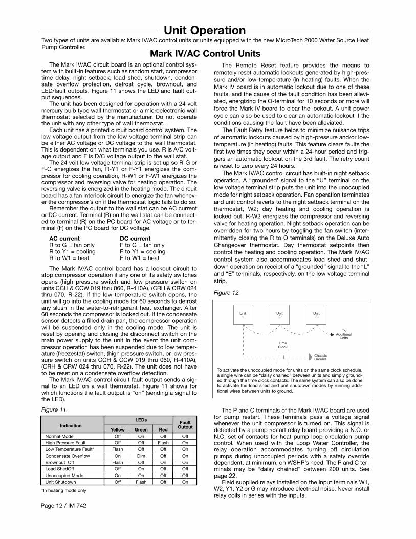
Figure 12.
The P and C terminals of the Mark IV/AC board are usedfor pump restart. These terminals pass a voltage signalwhenever the unit compressor is turned on. This signal isdetected by a pump restart relay board providing a N.O. orN.C. set of contacts for heat pump loop circulation pumpcontrol. When used with the Loop Water Controller, therelay operation accommodates turning off circulationpumps during unoccupied periods with a safety overridedependent, at minimum, on WSHP’s need. The P and C ter-minals may be “daisy chained” between 200 units. Seepage 22.
Field supplied relays installed on the input terminals W1,W2, Y1, Y2 or G may introduce electrical noise. Never installrelay coils in series with the inputs.
ChassisGround
Unit1
Unit2
Unit3
ToAdditional
Units
TimeClock
To activate the unoccupied mode for units on the same clock schedule,a single wire can be “daisy chained” between units and simply ground-ed through the time clock contacts. The same system can also be doneto activate the load shed and unit shutdown modes by running addi-tional wires between units to ground.
Two types of units are available: Mark IV/AC control units or units equipped with the new MicroTech 2000 Water Source HeatPump Controller.
Mark IV/AC Control Units
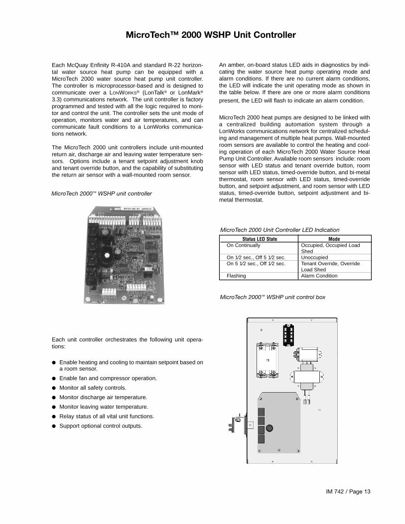
Each McQuay Enfinity R-410A and standard R-22 horizon-tal water source heat pump can be equipped with aMicroTech 2000 water source heat pump unit controller.The controller is microprocessor-based and is designed tocommunicate over a LONWORKS® (LonTalk® or LonMark®
3.3) communications network. The unit controller is factoryprogrammed and tested with all the logic required to moni-tor and control the unit. The controller sets the unit mode ofoperation, monitors water and air temperatures, and cancommunicate fault conditions to a LonWorks communica-tions network.
The MicroTech 2000 unit controllers include unit-mountedreturn air, discharge air and leaving water temperature sen-sors. Options include a tenant setpoint adjustment knoband tenant override button, and the capability of substitutingthe return air sensor with a wall-mounted room sensor.
Each unit controller orchestrates the following unit opera-tions:
● Enable heating and cooling to maintain setpoint based ona room sensor.
● Enable fan and compressor operation.
● Monitor all safety controls.
● Monitor discharge air temperature.
● Monitor leaving water temperature.
● Relay status of all vital unit functions.
● Support optional control outputs.
IM 742 / Page 13
MicroTech™ 2000 WSHP Unit Controller
MicroTech 2000 Unit Controller LED Indication
Status LED State ModeOn Continually Occupied, Occupied Load
ShedOn 1⁄2 sec., Off 5 1⁄2 sec. UnoccupiedOn 5 1⁄2 sec., Off 1⁄2 sec. Tenant Override, Override
Load ShedFlashing Alarm Condition
An amber, on-board status LED aids in diagnostics by indi-cating the water source heat pump operating mode andalarm conditions. If there are no current alarm conditions,the LED will indicate the unit operating mode as shown inthe table below. If there are one or more alarm conditionspresent, the LED will flash to indicate an alarm condition.
MicroTech 2000 heat pumps are designed to be linked witha centralized building automation system through aLonWorks communications network for centralized schedul-ing and management of multiple heat pumps. Wall-mountedroom sensors are available to control the heating and cool-ing operation of each MicroTech 2000 Water Source HeatPump Unit Controller. Available room sensors include: roomsensor with LED status and tenant override button, roomsensor with LED status, timed-override button, and bi-metalthermostat, room sensor with LED status, timed-overridebutton, and setpoint adjustment, and room sensor with LEDstatus, timed-override button, setpoint adjustment and bi-metal thermostat.
MicroTech 2000™ WSHP unit controller
MicroTech 2000™ WSHP unit control box
Page 14 / IM 742
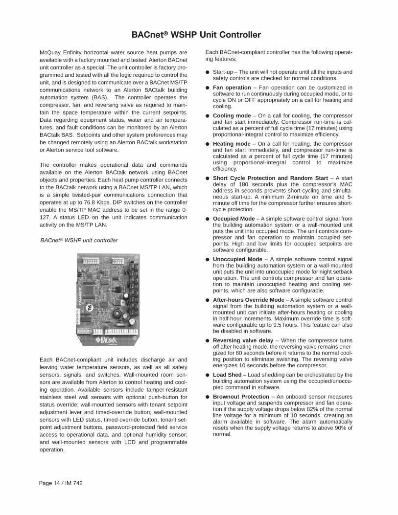
McQuay Enfinity horizontal water source heat pumps areavailable with a factory mounted and tested Alerton BACnetunit controller as a special. The unit controller is factory pro-grammed and tested with all the logic required to control theunit, and is designed to communicate over a BACnet MS/TPcommunications network to an Alerton BACtalk buildingautomation system (BAS). The controller operates thecompressor, fan, and reversing valve as required to main-tain the space temperature within the current setpoints.Data regarding equipment status, water and air tempera-tures, and fault conditions can be monitored by an AlertonBACtalk BAS. Setpoints and other system preferences maybe changed remotely using an Alerton BACtalk workstationor Alerton service tool software.
The controller makes operational data and commandsavailable on the Alerton BACtalk network using BACnetobjects and properties. Each heat pump controller connectsto the BACtalk network using a BACnet MS/TP LAN, whichis a simple twisted-pair communications connection thatoperates at up to 76.8 Kbps. DIP switches on the controllerenable the MS/TP MAC address to be set in the range 0-127. A status LED on the unit indicates communicationactivity on the MS/TP LAN.
Each BACnet-compliant unit includes discharge air andleaving water temperature sensors, as well as all safetysensors, signals, and switches. Wall-mounted room sen-sors are available from Alerton to control heating and cool-ing operation. Available sensors include tamper-resistantstainless steel wall sensors with optional push-button forstatus override; wall-mounted sensors with tenant setpointadjustment lever and timed-override button; wall-mountedsensors with LED status, timed-override button, tenant set-point adjustment buttons, password-protected field serviceaccess to operational data, and optional humidity sensor;and wall-mounted sensors with LCD and programmableoperation.
BACnet® WSHP unit controller
Each BACnet-compliant controller has the following operat-ing features:
● Start-up – The unit will not operate until all the inputs andsafety controls are checked for normal conditions.
● Fan operation – Fan operation can be customized insoftware to run continuously during occupied mode, or tocycle ON or OFF appropriately on a call for heating andcooling.
● Cooling mode – On a call for cooling, the compressorand fan start immediately. Compressor run-time is cal-culated as a percent of full cycle time (17 minutes) usingproportional-integral control to maximize efficiency.
● Heating mode – On a call for heating, the compressorand fan start immediately, and compressor run-time iscalculated as a percent of full cycle time (17 minutes)using proportional-integral control to maximize efficiency.
● Short Cycle Protection and Random Start – A startdelay of 180 seconds plus the compressor’s MACaddress in seconds prevents short-cycling and simulta-neous start-up. A minimum 2-minute on time and 5-minute off time for the compressor further ensures short-cycle protection.
● Occupied Mode – A simple software control signal fromthe building automation system or a wall-mounted unitputs the unit into occupied mode. The unit controls com-pressor and fan operation to maintain occupied set-points. High and low limits for occupied setpoints aresoftware configurable.
● Unoccupied Mode – A simple software control signalfrom the building automation system or a wall-mountedunit puts the unit into unoccupied mode for night setbackoperation. The unit controls compressor and fan opera-tion to maintain unoccupied heating and cooling set-points, which are also software configurable.
● After-hours Override Mode – A simple software controlsignal from the building automation system or a wall-mounted unit can initiate after-hours heating or coolingin half-hour increments. Maximum override time is soft-ware configurable up to 9.5 hours. This feature can alsobe disabled in software.
● Reversing valve delay – When the compressor turnsoff after heating mode, the reversing valve remains ener-gized for 60 seconds before it returns to the normal cool-ing position to eliminate swishing. The reversing valveenergizes 10 seconds before the compressor.
● Load Shed – Load shedding can be orchestrated by thebuilding automation system using the occupied/unoccu-pied command in software.
● Brownout Protection – An onboard sensor measuresinput voltage and suspends compressor and fan opera-tion if the supply voltage drops below 82% of the normalline voltage for a minimum of 10 seconds, creating analarm available in software. The alarm automaticallyresets when the supply voltage returns to above 90% ofnormal.
BACnet® WSHP Unit Controller
IM 742 / Page 15
● Condensate Overflow Protection – A liquid sensor atthe top of the drain pan senses a high water level. Uponsensing water, cooling operation is suspended, whileheating operation is allowed. The controller creates analarm available in software. The alarm automaticallyresets when the water level returns to normal.
● Safety Control – The unit monitors refrigerant pressureand generates separate high-pressure and low-pressurealarms available in software. While either alarm is active,compressor operation is suspended. In a refrigerant low-temperature condition, an alarm occurs and the unitoperates in cooling mode for 60 seconds to defrost theheat exchanger, after which compressor operation issuspended. These alarms can be reset in software or bycycling power to the controller.
● Attained Temperature and Water TemperatureAlarms –Attained temperature, water temperaturealarms with software-adjustable setpoints are availablein software. The controller samples supply air andrecords attained temperatures for heating and cooling. Ifafter two hours of operation, the attained temperaturedoes not meet the software-configurable setpoint forheating or cooling as appropriate, a software alarmoccurs. The alarm automatically resets when the attained
temperature is within setpoints. The controller also mon-itors leaving water temperature. If the leaving water tem-perature is outside software-configurable setpoints, com-pressor operation is suspended and high or low watertemperature alarms occur. The alarm automaticallyresets when the water temperature returns to within 6deg. F of the setpoint.
● Unit Self-test Mode – While the unit is in occupiedmode, a self-test can be initiated via software. Upon initi-ation of the test, compressor operation is suspended fora minimum of five minutes, cooling attained temperaturesare cleared, and attained temperature alarms arecleared. The unit then switches to full heat for four min-utes and then records the attained supply air tempera-ture. Compressor operation is then suspended for fiveminutes. The unit then switches to full cooling for fourminutes and the attained supply air temperature isrecorded. Attained temperature alarms are set if theattained temperatures failed to reach alarm setpointsduring heating or cooling.
BACnet® WSHP Unit Controller

Page 16 / IM 742
Thermostat Connection DiagramsMark IV/AC Units – Unit Sizes 007-070
Deluxe Automatic Changeover Thermostat (P/N 105571001)
Standard Automatic & Manual Changeover Thermostat (P/N 105570701)
Non-Programmable Electronic Thermostat (P/N 105570801)
WSHP Mark IV/AC Board Low Voltage Terminal Strip
O W2 G W1 Y1 F E L U A P V R C
G W Y R
Thermostat Terminals
WSHP Mark IV/AC Board Low Voltage Terminal Strip
O W2 G W1 Y1 F E L U A P V R C
Thermostat Terminals
O W2 G W1 Y1 A R
Daisy-chain connection toadditional units Mark IV/ACboard “U” terminals
Time Clock(by others)
WSHP Mark IV/AC Board Low Voltage Terminal Strip
O W2 G W1 Y1 F E L U A P V R C
Thermostat Terminals
G W1 Y1 A Rc Rh
WSHP Mark IV/AC Board Low Voltage Terminal Strip
O W2 G W1 Y1 F E L U A P V R C
Thermostat Terminals
G W1 Y1 R Rc C
P/N 106069001Includes Thermostat and Subbase(Honeywell P/N T834C2416)Fan Switch: Auto / OnSystem Switch: Heat / Off / Cool
P/N 105570701Includes Thermostat and Subbase(Honeywell P/N’s T874A1598 and Q674E1460)Fan Switch: Auto / OnSystem Switch: Off / Heat / Auto / Cool
P/N 105571003Includes Thermostat and Subbase(Honeywell P/N’s T874C1869 and Q674C1579)Fan Switch: Auto / On / Tenant OverrideSystem Switch: Off / Auto
Note: Thermostat provides a fixed 13°F differential between W1 and W2.
Operation: The units Mark IV/AC boardwill be in the occupied mode, monitoringterminals W1 and Y1 and ignoring terminal W2, when the time clock contacts are open. The Mark IV/AC boardwill be in the unoccupied mode, monitor-ing terminal W2 and ignoring terminals W1 and Y1, when the time clockcontacts are closed. No cooling isallowed during the unoccupied mode.The tenant override feature of the thermostat allows the occupant to force a2-hour override of unoccupied mode.During this override period the W1 and Y1terminals are monitored and the W2 ter-minal is ignored (same as occupied).
P/N 105570801Includes Thermostat and Wall Plate(Honeywell P/N T8524D1064)
Manual Changeover Thermostat (P/N 106069001)

WSHP Mark IV/AC Board Low Voltage Terminal
O W2 G W1 Y1 F E L U A P V R C
Thermostat Terminals
G W1 Y1 R Rc C
Programmable Electronic Thermostat (P/N 105570901)
P/N 105570901Includes Thermostat and Wall Plate(Honeywell P/N T8524D2111)
Thermostat Connection DiagramsMark IV/AC Units – Unit Sizes 007-070
7-Day Programmable Electronic Thermostat w/Sensor (P/N 106710801)
WSHP Mark IV/AC Board Low Voltage Terminal
O W2 G W1 Y1 F E L U A P V R C
Thermostat Terminals
G W1 Y1 R Rc C S1 S2 S1 S2
Sensor
P/N 106710801Includes Thermostat, Wall Plate, andWall Sensor
(Optional) MicroTech Wall Sensor – Wiring Diagram
Sensor Tenant Override Setpoint Bi-Metal No. of Conductors Part No. Switch Adjustment Pot Thermometer Required
107230301 Yes No No 4 + Shield107230401 Yes No Yes 4 + Shield107230501 Yes Yes No 4 + Shield107230601 Yes Yes Yes 4 + Shield
62 63 64 65 66 67 68
12 12 12 12 12 12 12
6 7 8 9 10 11 12 J2
BlkRed
GrnWht
Terminal Board #1
Wall Sensor
Stranded Wire(Blk, Wht, Grn, Red)
MicroTech Controller
Locate the sensor on a wall where exposure to unrestrict-ed air circulation represents the average temperature ofthe space. A common mistake is to mount the sensor tooclose to the supply air diffuser in a room. This causes shortcycling of the air conditioning unit and large room tempera-ture swings.
Note: All sensors have black (common), white (thermistor),and red (LED) wires. With the tenant override and /or setpoint adjustment option, a green wire is provided. Theoptional thermometer does not affect wiring.
Refer to IM 529 for detailed installation instructions.
IM 742 / Page 17
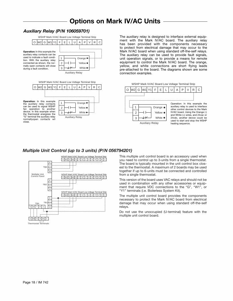
This multiple unit control board is an accessory used whenyou need to control up to 3-units from a single thermostat.The board is typically mounted in the unit control box clos-est to the thermostat. A maximum of 2 boards may be usedtogether if up to 6-units must be connected and controlledfrom a single thermostat.
This version of the board uses VAC relays and should not beused in combination with any other accessories or equip-ment that require VDC connections to the “G”, “W1”, or“Y1” terminals (i.e. Boilerless System Kit).
The multiple unit control board provides the componentsnecessary to protect the Mark IV/AC board from electricaldamage that may occur when using standard off-the-selfrelays.
Do not use the unoccupied (U-terminal) feature with themultiple unit control board.
Multiple Unit Control (up to 3 units) (P/N 056794201)
O W2 G W1 Y1 F E L U A P V R C
WSHP Mark IV/AC Board Low Voltage Terminal Strip
O W2 G W1 Y1 F E L U A P V R C
O W2 G W1 Y1 F E L U A P V R C
R
Y
G
W
R
Y
G
W
R
Y
G
WG W Y R C
G W1 Y1 R Rc C
Thermostat Terminals
WSHP Mark IV/AC Board Low Voltage Terminal Strip
WSHP Mark IV/AC Board Low Voltage Terminal Strip
Multiple UnitControl Panel
TB3
TB2
TB1TB4
Page 18 / IM 742
WSHP Mark IV/AC Board Low Voltage Terminal Strip
O W2 G W1 Y1 F E L U A P V R C
1
2
3
Auxiliary Relay
Orange
Yellow
White
WSHP Mark IV/AC Board Low Voltage Terminal Strip
O W2 G W1 Y1 F E L U A P V R C
1
2
3
Auxiliary Relay
Orange
Yellow
White
Options on Mark IV/AC Units
The auxiliary relay is designed to interface external equip-ment with the Mark IV/AC board. The auxiliary relay has been provided with the components necessary to protect from electrical damage that may occur to theMark IV/AC board when using standard off-the-self relays.The auxiliary relay can be used to provide fault signals, unit operation signals, or to provide a means for remoteequipment to control the Mark IV/AC board. The orange,yellow, and white connections are short flying leads pre-attached to the board. The diagrams shown are someconnection examples.
Auxiliary Relay (P/N 106059701)WSHP Mark IV/AC Board Low Voltage Terminal Strip
O W2 G W1 Y1 F E L U A P V R C
1
2
3
Auxiliary Relay
Orange
Yellow
White
Operation: In this example theauxiliary relay contacts can beused to indicate a fault condi-tion. With the auxiliary relayconnected as shown, the nor-mally open contacts will closeduring a fault condition.
Operation: In this examplethe auxiliary relay contactscan be used to signal WSHPfan operation to anotherdevice. In this example whenthe thermostat energizes the“G” terminal the auxiliary relaynormallyopen contacts wilclose.
Operation: In this example theauxiliary relay is used to interfaceother control devices to the MarkIV/AC board. Using the Orange (-)and White (+) wires, and 24vac or24vdc, another device could beused to start and stop the WSHPheating sequence.
IM 742 / Page 19
Options on Mark IV/AC Units
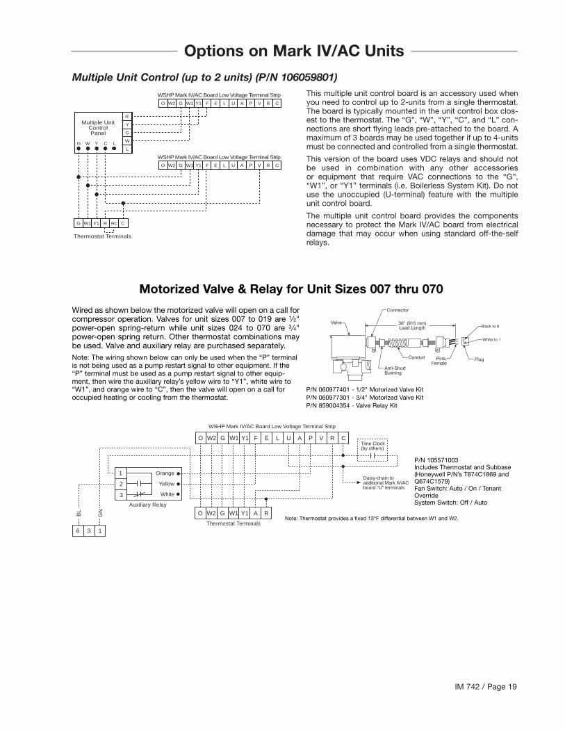
Multiple Unit Control (up to 2 units) (P/N 106059801)This multiple unit control board is an accessory used whenyou need to control up to 2-units from a single thermostat.The board is typically mounted in the unit control box clos-est to the thermostat. The “G”, “W”, “Y”, “C”, and “L” con-nections are short flying leads pre-attached to the board. Amaximum of 3 boards may be used together if up to 4-unitsmust be connected and controlled from a single thermostat.
This version of the board uses VDC relays and should notbe used in combination with any other accessories or equipment that require VAC connections to the “G”,“W1”, or “Y1” terminals (i.e. Boilerless System Kit). Do notuse the unoccupied (U-terminal) feature with the multipleunit control board.
The multiple unit control board provides the componentsnecessary to protect the Mark IV/AC board from electricaldamage that may occur when using standard off-the-selfrelays.
WSHP Mark IV/AC Board Low Voltage Terminal Strip
O W2 G W1 Y1 F E L U A P V R C
R
Y
G
W
L
G W1 Y1 R Rc C
Thermostat Terminals
Multiple UnitControlPanel
WSHP Mark IV/AC Board Low Voltage Terminal Strip
O W2 G W1 Y1 F E L U A P V R C
G W Y C L
WSHP Mark IV/AC Board Low Voltage Terminal Strip
O W2 G W1 Y1 F E L U A P V R C
1
2
3
Auxiliary Relay
Orange
Yellow
White
O W2 G W1 Y1 A R
6 3 1
Time Clock(by others)
Daisy-chain toadditional Mark IV/ACboard “U” terminals
Thermostat Terminals
BL
GN
Motorized Valve & Relay for Unit Sizes 007 thru 070
Wired as shown below the motorized valve will open on a call forcompressor operation. Valves for unit sizes 007 to 019 are 1⁄2"power-open spring-return while unit sizes 024 to 070 are 3⁄4"power-open spring return. Other thermostat combinations maybe used. Valve and auxiliary relay are purchased separately.Note: The wiring shown below can only be used when the “P” terminalis not being used as a pump restart signal to other equipment. If the“P” terminal must be used as a pump restart signal to other equip-ment, then wire the auxiliary relay’s yellow wire to “Y1”, white wire to“W1”, and orange wire to “C”, then the valve will open on a call foroccupied heating or cooling from the thermostat.
631
Black to 6
White to 1
PlugPins,Female
Conduit
Anti-ShortBushing
Connector
Valve 36" (915 mm)Lead Length
P/N 105571003Includes Thermostat and Subbase(Honeywell P/N’s T874C1869 andQ674C1579)Fan Switch: Auto / On / TenantOverrideSystem Switch: Off / Auto
Note: Thermostat provides a fixed 13°F differential between W1 and W2.
P/N 060977401 - 1/2" Motorized Valve KitP/N 060977301 - 3/4" Motorized Valve KitP/N 859004354 - Valve Relay Kit

Page 20 / IM 742
Pump Restart Relay Kit P/N 061419001
Used as an option with the Mark IV/AC board, the pumprestart relay kit provides a means to alert the loop watercontroller that water flow is required by a WSHP so that thesystem pump can be started. This option is typically used ininstallations where the pump may be shut off when there isno need for water flow (i.e. temperature OK, etc.). Typicallyonly one pump restart relay kit is required per installation asup to 200 Mark IV/AC boards can be “daisy-chained”together.
The Mark IV/AC “P” terminal is used to determine WSHPcompressor operation. Wired as shown below, when com-pressor operation is required, the Mark IV/AC “P” terminal
will change state causing a contact closure between termi-nal 58 and 64 signaling the loop water control (LWC) panelto restart the loop pump if Off.
The pump restart relay kit is typically mounted within oneWSHP or within the LWC panel, whichever is more conve-nient, diagrams are provided below for each location. Toinstall the relay, remove the cover on the double-faced tapeprovided on the relay and attach the relay either to theinside of the LWC panel (adjacent to circuit breaker CB1and terminal block TB3) or in the WSHP control box (in aconvenient location), then wire as shown below.
WSHP Mark IV/AC Board Low Voltage Terminal Strip
PumpRestartRelay
7
6
5
4
3
2
1
O W2 G W1 Y1 F E L U A P V R C
LoopWater
ControllerTerminals
Daisy chain to other MarkIV/AC board “P” and “C”terminals
64
58
65
WSHP Mark IV/AC Board Low Voltage Terminal Strip (Circuit 1)
PumpRestartRelay
7
6
5
4
3
2
1
O W2 G W1 Y1 F E L U A P V R C
Power byothers
Daisy chain to other MarkIV/AC board “P” and “C”terminals
Wiring Pump Restart Relay when Installed within the LWC Panel
Wiring Pump Restart Relay when Installed within a WSHP Control Box
IM 742 / Page 21
Field Installed Options on MicroTech 2000 Units
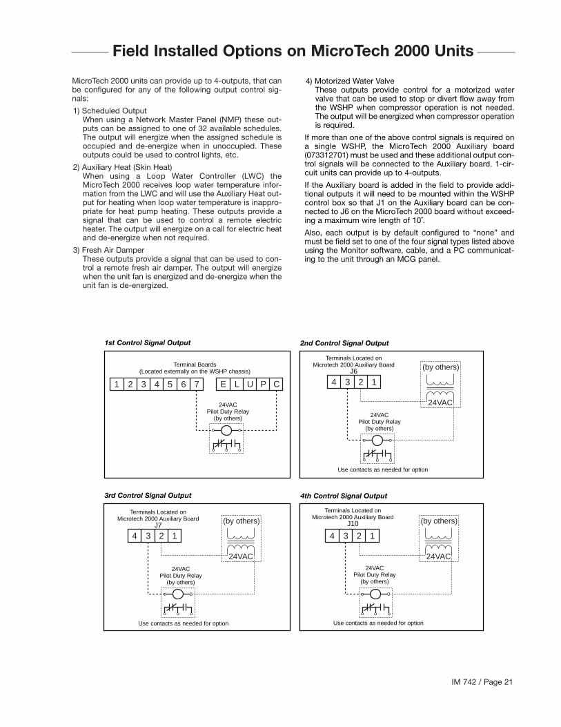
MicroTech 2000 units can provide up to 4-outputs, that canbe configured for any of the following output control sig-nals:
1) Scheduled OutputWhen using a Network Master Panel (NMP) these out-puts can be assigned to one of 32 available schedules.The output will energize when the assigned schedule isoccupied and de-energize when in unoccupied. Theseoutputs could be used to control lights, etc.
2) Auxiliary Heat (Skin Heat)When using a Loop Water Controller (LWC) theMicroTech 2000 receives loop water temperature infor-mation from the LWC and will use the Auxiliary Heat out-put for heating when loop water temperature is inappro-priate for heat pump heating. These outputs provide asignal that can be used to control a remote electricheater. The output will energize on a call for electric heatand de-energize when not required.
3) Fresh Air DamperThese outputs provide a signal that can be used to con-trol a remote fresh air damper. The output will energizewhen the unit fan is energized and de-energize when theunit fan is de-energized.
1 2 3 4 5 6 7 E L U P C 4 3 2 1
(by others)
24VAC
4 3 2 1
(by others)
24VAC
4 3 2 1
(by others)
24VAC
4) Motorized Water ValveThese outputs provide control for a motorized watervalve that can be used to stop or divert flow away fromthe WSHP when compressor operation is not needed.The output will be energized when compressor operationis required.
If more than one of the above control signals is required ona single WSHP, the MicroTech 2000 Auxiliary board(073312701) must be used and these additional output con-trol signals will be connected to the Auxiliary board. 1-cir-cuit units can provide up to 4-outputs.
If the Auxiliary board is added in the field to provide addi-tional outputs it will need to be mounted within the WSHPcontrol box so that J1 on the Auxiliary board can be con-nected to J6 on the MicroTech 2000 board without exceed-ing a maximum wire length of 10˝.
Also, each output is by default configured to “none” andmust be field set to one of the four signal types listed aboveusing the Monitor software, cable, and a PC communicat-ing to the unit through an MCG panel.
1st Control Signal Output 2nd Control Signal Output
3rd Control Signal Output 4th Control Signal Output
Terminal Boards(Located externally on the WSHP chassis)
24VACPilot Duty Relay
(by others)
Terminals Located onMicrotech 2000 Auxiliary Board
J6
24VACPilot Duty Relay
(by others)
Use contacts as needed for option
Terminals Located onMicrotech 2000 Auxiliary Board
J7
24VACPilot Duty Relay
(by others)
Use contacts as needed for option
Terminals Located onMicrotech 2000 Auxiliary Board
J10
24VACPilot Duty Relay
(by others)
Use contacts as needed for option
Page 22 / IM 742
Read Outputs
Check Timers
HiPres. Sw ?
Brown Out ?
Low Temp Sw ?
Lo Shed ?
N S B ?
Cond. Overflow?
R - W 1 ?
R -Y 1 ?
Stop Comp.
Flash Red LED
Stop Fan
Flash Green LED
Stop Comp.
Htg Mode?
Stop Comp.
Flash Yellow LED
Stop Comp.
Turn On Red LED
R - W 2 ?
Start Comp.
Cooling Mode
Turn On Yellow LED
Stop Comp.
Reversing Valve On
Time Delay
Start Comp.
Start Comp.
No
No
Ye s
No
Ye s
No
No
No
No
No
No
No
No
Ye s
Ye s
Ye s
Ye s
Ye s
Ye s
Ye s
Ye s
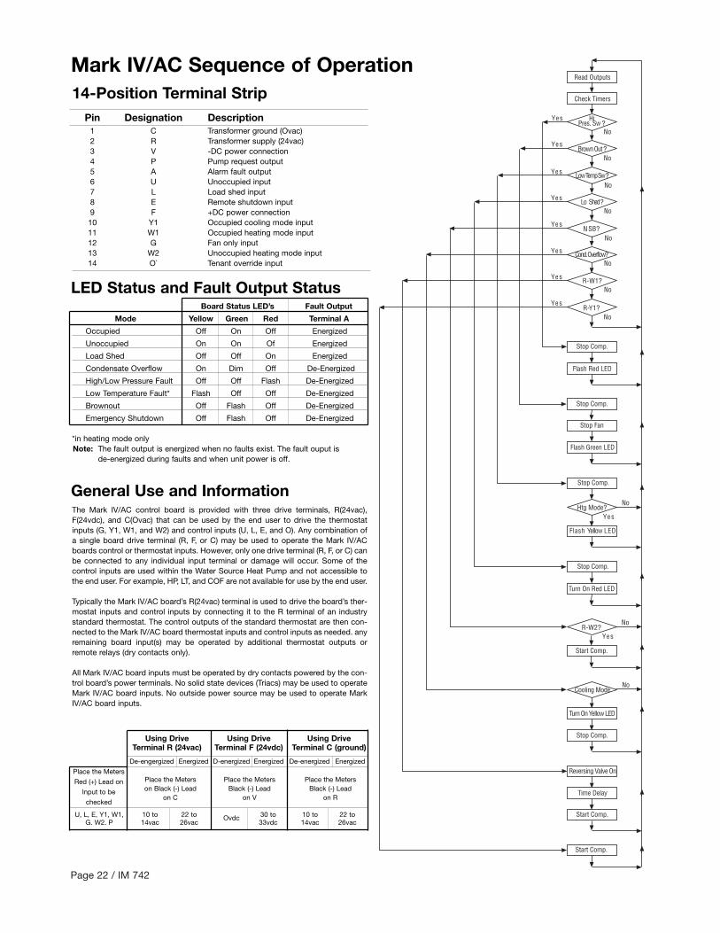
14-Position Terminal StripPin Designation Description
1 C Transformer ground (Ovac)2 R Transformer supply (24vac)3 V -DC power connection4 P Pump request output5 A Alarm fault output6 U Unoccupied input7 L Load shed input8 E Remote shutdown input9 F +DC power connection10 Y1 Occupied cooling mode input11 W1 Occupied heating mode input12 G Fan only input13 W2 Unoccupied heating mode input14 O` Tenant override input
Board Status LED’s Fault Output
Mode Yellow Green Red Terminal A
Occupied Off On Off Energized
Unoccupied On On Of Energized
Load Shed Off Off On Energized
Condensate Overflow On Dim Off De-Energized
High/Low Pressure Fault Off Off Flash De-Energized
Low Temperature Fault* Flash Off Off De-Energized
Brownout Off Flash Off De-Energized
Emergency Shutdown Off Flash Off De-Energized
*in heating mode onlyNote: The fault output is energized when no faults exist. The fault ouput is
de-energized during faults and when unit power is off.
The Mark IV/AC control board is provided with three drive terminals, R(24vac),F(24vdc), and C(Ovac) that can be used by the end user to drive the thermostatinputs (G, Y1, W1, and W2) and control inputs (U, L, E, and O). Any combination ofa single board drive terminal (R, F, or C) may be used to operate the Mark IV/ACboards control or thermostat inputs. However, only one drive terminal (R, F, or C) canbe connected to any individual input terminal or damage will occur. Some of thecontrol inputs are used within the Water Source Heat Pump and not accessible tothe end user. For example, HP, LT, and COF are not available for use by the end user.
Typically the Mark IV/AC board’s R(24vac) terminal is used to drive the board’s ther-mostat inputs and control inputs by connecting it to the R terminal of an industrystandard thermostat. The control outputs of the standard thermostat are then con-nected to the Mark IV/AC board thermostat inputs and control inputs as needed. anyremaining board input(s) may be operated by additional thermostat outputs orremote relays (dry contacts only).
All Mark IV/AC board inputs must be operated by dry contacts powered by the con-trol board’s power terminals. No solid state devices (Triacs) may be used to operateMark IV/AC board inputs. No outside power source may be used to operate MarkIV/AC board inputs.
Using Drive Using Drive Using DriveTerminal R (24vac) Terminal F (24vdc) Terminal C (ground)
De-engergized Energized D-energized Energized De-energized Energized
Place the Meters
Red (+) Lead on Place the Meters Place the Meters Place the Meters
Input to be on Black (-) Lead Black (-) Lead Black (-) Lead
checkedon C on V on R
U, L, E, Y1, W1, 10 to 22 to Ovdc 30 to 10 to 22 toG. W2. P 14vac 26vac 33vdc 14vac 26vac
LED Status and Fault Output Status
General Use and Information
Mark IV/AC Sequence of Operation

IM 742 / Page 23
Low Voltage, check powersupply voltage
Fuse may be blown, circuitbreaker is open
Wires may be loose or broken.Replace or retighten wires
Unit Control, check thermostatfor correct wiring or bad t’stat
Fan, nor Compressor Run
Unit
Compressor runsin short cycle
Fan operates,Compressor does not
Compressor attempts to startbut doesn’t Insufficient cooling or heating
Check compressor wiring fordefective wiring or looseconnection
Check themostat for improperlocation
Check for defective compressorinternal windings with ohm meter
Check for bad compressorcapacitor
Check for lock rotor amp draw
Check for proper air flow. Filtercould be dirty
Check blower assembly fordirt or bad fan motor capacity
Check for low refrigerant charge
Check amp draw on blowerassembly
Check capacitor
Check wiring - loose or brokenand check for badconnection
Hi pressure lockout -A. Cool mode, check water flowB. Heating mode, check air flowC. Check reversing valve for proper valve position
Check compressor overloadmake sure it’s closed
Check compressor to ground,or for internal short to ground.
Compressor winding may beopen. Check continuity withohm meter
Check wiring - loose or brokenand check for badconnection
Check relays and contacts,also capacitor and wiring
Check high pressure switchand low temperature switch tosee if unit is cycling on the safety
Check to see if the reversingvalve is not hung up and isoperating correctly
Check condensate overflowswitch in cool mode of operation
Troubleshooting Water Source Heat Pump
To avoid electrical shock, personal injury or death, be sure that field wiring complies with local and national fire, safety, and electricalcodes, and voltage to the system is within the limits shown in the job-specific drawings and unit electrical data plate(s).Power supply to unit must be disconnected when making field connections. To avoid electrical shock, personal injury or death, be sureto rigorously adhere to field wiring procedures regarding proper lockout and tagout of components.
DANGER
Page 24 / IM 742
Troubleshooting
The in and outs of Enfinity™ R-410ARefrigerant 410A is a non-ozone depleting blend of tworefrigerants HFC-125 and HFC-32 in a fifty percent mixture.Refrigerant 410A exhibits higher operating pressure andrefrigeration capacity than R-22. R-410A refrigerant isintended for use in new air conditioning application that hastraditionally been serviced by HCFC-22 or R-22. Due tohigher capacity and pressure of R-410A, it is not recom-mended as a retrofit to existing R-22 systems.
Although R-410A is non-flammable at ambient temper-ature and atmosphere pressure, it can become com-bustible under pressure when mixed with air. (NOTE: R-410A should not be mixed with air under pressure forleak testing. Pressure mixtures of dry nitrogen and R-410Acan be used for leak testing.)
LubricationR410A should be used only with polyolester (POE) oil. TheHFC refrigerant components in R-410A will not be compat-ible with mineral oil or alkylbenzene lubricants. R-410A sys-tems will be charged with the OEM recommended lubri-cant, ready for use with R-410A.
ChargingDue to the zeotropic nature of R-410A, it should be chargedas a liquid. In situations where vapor is normally chargedinto a system, a valve should be installed in the chargingline to flash the liquid to vapor while charging.
WarningIt is very important to make certain that the recycle orrecovery equipment used is designed for R-410A. The pres-sure of R-410A refrigerant is approximately 60 percentgreater than that of R-22. Pressure gauges require a rangeup to 800 PSIG high side and 250 PSIG low side. Recoverycylinders require a 400 PSIG rating – do not put R-410A ina 300 PSIG rated cylinder.
(NOTE: because a water source heat pump operates undera wide range of water and air temperatures, the valuesprinted below are to be taken as suggested pressure andtemperatures.) All McQuay water source heat pumps aredesigned for commercial use. The units are designed forthe cooling mode of operation and fail safe to cooling. Therevising valve is energized for the heating mode of opera-tion.
Superheat Head Pressure Water Delta T
8 to 14 degrees 335-355 PSIG 10° to 12°
All information above is based on ISO standard 13256-1and are tested at these conditions.

ChargeUndercharge System Low Low Low High Low Low Low Low Pressure(Possible Leak)
Overcharge System High High High Normal High Normal High Pressure
Low Air Flow Heating High High High Low High Low High Pressure
Low Air Flow Cooling Low Low Low High High Low Low Temp
Low Water Flow Heating Low Low High Low High Low Temp
Low Water Flow Cooling High High High High Low Low High High Pressure
High Air Flow Heating Low Low Low Low High Low Low Low Temp
High Air Flow Cooling Low High Normal High Low Low Normal High Pressure
High Water Flow Heating Normal Low Normal High Normal Normal Low High Pressure
High Water Flow Cooling Low Low Low Low High Normal Low Low Temp
TXV Restricted High Low High High Low Low
Air Water SafetySymptom Head Suction Compressor Super Subcooling Temp (loops) Temp Lock
Pressure Pressure Amp Draw Heat Differential Differential Out
IM 742 / Page 25
HighNormal
LowNormal
LowNormal
NormalLow
LowNormal
NormalLow
Troubleshooting Refrigeration Circuit
General Maintenance1. Normal maintenance on all conditioners is generally lim-
ited to filter changes. Motors used with WSHP unit size007 through 070 are provided with permanently lubricat-ed motors and require no oiling even though oil caps maybe provided.
2. Filter changes are required at regular intervals. The timeperiod between changes will depend upon the projectrequirements. Some applications such as motels pro-duce a lot of lint from carpeting and linen changes, andwill require more frequent filter changes. It is suggestedthat the filter be checked at 60-day intervals for the firstyear until experience is acquired. If light cannot be seenthrough the filter when held up to sunlight or a bright light,it should be changed. A more critical standard may bedesirable.
3. The condensate drain pan should be checked annuallyand cleaned and flushed as required.
4. Recording of performance measurements of volts, amps,and water temperature differences (both heating andcooling) is recommended. A comparison of logged datawith start-up and other annual data is useful as an indi-cator of general equipment condition.
5. Periodic lockouts almost always are caused by air orwater problems. The lockout (shutdown) of the condition-er is a normal protective result. Check for dirt in the watersystem, water flow rates, water temperatures, airflowrates (may be dirty filter), and air temperatures. If thelockout occurs in the morning following a return fromnight setback, entering air below machine limits may bethe cause.

Page 26 / IM 742
Cooling Mode – (Single Circuit Only Shown)
Return Air
Reversing Valve
Conditioned Air – (Cooling)
ThermalExpansion Valve
Co-Axial HeatExchanger
Blower
Coil – Air to RefrigerantHeat Exchanger
Water In
Water Out
Sensing Bulb andCapillary Tube
Compressor
Heating Mode – (Single Circuit Only Shown)
Return Air
ThermalExpansion Valve
Co-Axial HeatExchanger
Reversing Valve
Conditioned Air – (Heating)
Blower
Water In
Water Out
Sensing Bulband Capillary Tube
Compressor
Coil – Air to Refrigerant Heat Exchanger
Cooling Refrigeration CycleWhen the wall thermostat is calling for COOLING, the reversing valve directs the flow of the refrigerant, a hot gas, leaving thecompressor to the water-to-refrigerant heat exchanger. Here the heat is removed by the water and the hot gas condenses tobecome a liquid. The liquid then flows through a thermal expansion metering system to the air-to-refrigerant heat exchangercoil. The liquid then evaporates becoming a gas, at the same time absorbing heat and cooling the air passing over the sur-faces of the coil. The refrigerant then flows as a low pressure gas through the reversing valve and back to the suction side ofthe compressor to complete the cycle.
Heating Refrigeration CycleWhen the wall thermostat is calling for HEATING, the reversing valve directs the flow of the refrigerant, a hot gas, leaving thecompressor to the air-to-refrigerant heat exchanger coil. Here the heat is removed by the air passing over the surfaces of thecoil and the hot gas condenses to become a liquid. The liquid then flows through a capillary thermal expansion metering sys-tem to the water-to-refrigerant heat exchanger. The liquid then evaporates becoming a gas, at the same time absorbing heatand cooling the water. The refrigerant then flows as a low pressure gas through the reversing valve and back to the suctionside of the compressor to complete the cycle.
Typical Refrigeration Cycles

©2005 McQuay International • 800.432.1342 • www.mcquay.com IM 742 (Rev. 10-05)
®
Warranty
All McQuay equipment is sold pursuant to its standard terms and conditions of sale, including LimitedProduct Warranty. Consult your local McQuay Representative for warranty details. Refer to Form 933-43285Y. To find your local McQuay Representative, go to www.mcquay.com.
This document contains the most current product information as of this printing. For the most up-to-dateproduct information, please go to www.mcquay.com.
Products Manufactured in an ISO Certified Facility.
McQuay Training and Development
Now that you have made an investment in modern, efficient McQuay equipment, its care should be ahigh priority. For training information on all McQuay HVAC products, please visit us at www.mcquay.comand click on training, or call 540-248-9646 and ask for the Training Department.