Part No 479-0227 GB Troubleshooting Guide PRELIMINARY
152
PRELIMINARY ® Troubleshooting Guide 1200 Series Marine Auxiliary Engines GB Part No 479-0227
Transcript of Part No 479-0227 GB Troubleshooting Guide PRELIMINARY
PRELIMIN
ARY®
Troubleshooting Guide
1200 Series Marine Auxiliary Engines
GBPart No 479-0227

PRELIMIN
ARY
Important Safety InformationMost accidents that involve product operation, maintenance and repair are caused by failure to observe basic safety rules or precautions. An accident can often be avoided by recognizing potentially hazardous situations before an accident occurs. A person must be alert to potential hazards, including human factors that can affect safety. This person should also have the necessary training, skills and tools to perform these functions properly.
Improper operation, lubrication, maintenance or repair of this product can be dangerous and could result in injury or death.
Do not operate or perform any lubrication, maintenance or repair on this product, until you verify that you are authorized to perform this work, and have read and understood the operation, lubrication, maintenance and repair information.
Safety precautions and warnings are provided in this manual and on the product. If these hazard warnings are not heeded, bodily injury or death could occur to you or to other persons.
The hazards are identified by the “Safety Alert Symbol” and followed by a “Signal Word” such as “DANGER”, “WARNING” or “CAUTION”. The Safety Alert “WARNING” label is shown below.
WARNING
The meaning of this safety alert symbol is as follows:
Attention! Become Alert! Your Safety is Involved.
The message that appears under the warning explains the hazard and can be either written or pictorially presented.
A non-exhaustive list of operations that may cause product damage are identified by “NOTICE” labels on the product and in this publication.
Perkins cannot anticipate every possible circumstance that might involve a potential hazard. The warnings in this publication and on the product are, therefore, not all inclusive. You must not use this product in any manner different from that considered by this manual without first satisfying yourself that you have considered all safety rules and precautions applicable to the operation of the product in the location of use, including site-specific rules and precautions applicable to the worksite. If a tool, procedure, work method or operating technique that is not specifically recommended by Perkins is used, you must satisfy yourself that it is safe for you and for others. You should also ensure that you are authorized to perform this work, and that the product will not be damaged or become unsafe by the operation, lubrication, maintenance or repair procedures that you intend to use.
The information, specifications, and illustrations in this publication are on the basis of information that was available at the time that the publication was written. The specifications, torques, pressures, measurements, adjustments, illustrations, and other items can change at any time. These changes can affect the service that is given to the product. Obtain the complete and most current information before you start any job. Perkins dealers have the most current information available.
WARNING
When replacement parts are required for this product Perkins recommends using Perkins replacement parts or parts with equivalent specifications including, but not limited to, physical dimensions, type, strength and material.
Failure to heed this warning can lead to premature failures, product damage, personal injury or death.
In the United States, the maintenance, replacement, or repair of the emission control devices and systems may be performed by any repair establishment or individual of the owner’s choosing.
PRELIMIN
ARY479-0227 Table of Contents
Chapter Page
Electronic Troubleshooting .......................................................................1
Engine Governor ..............................................................................................................5
Timing Considerations ......................................................................................................5
Fuel Injection ....................................................................................................................5
Customer Parameters and Engine Speed Governing ......................................................5
ECM Lifetime Totals ..........................................................................................................6
Programmable Parameters ..............................................................................................6
Passwords ........................................................................................................................6
Electronic Service Tools ................................................................................................. 11
Required Service Tools ................................................................................................... 11
Optional Service Tools .................................................................................................... 11
Perkins Electronic Service Tool ...................................................................................... 11
Connecting the Electronic Service Tool and the Communication Adapter II ...................12
Shutdown........................................................................................................................12
Warning Lamp ................................................................................................................12
Lamp Check ...................................................................................................................12
Sensor locations on the left side of the engine ...............................................................15
Harness Wire Identification.............................................................................................17
Programming Parameters........................................................................21
Test ECM Mode ..............................................................................................................21
Program a new Electronic Control Module (ECM)..........................................................21
Rerate the engine. ..........................................................................................................22
Unlock parameters. ........................................................................................................22
Clear engine events and certain diagnostic trouble codes. ............................................22
Flash Programming a Flash File.....................................................................................22
PRELIMIN
ARYTable of Contents 479-0227
Installing Injector Codes .................................................................................................23
Customer Specified Parameters .............................................................25
Equipment ID ..................................................................................................................25
Rating Number ...............................................................................................................25
Engine Location ..............................................................................................................25
Coolant Level Switch ......................................................................................................25
System Operating Voltage Configuration .......................................................................26
Customer Password 1 ....................................................................................................26
Customer Password 2 ....................................................................................................26
CAN Communication Protocol Write Security ................................................................26
System Configuration Parameters..........................................................27
Symptom Troubleshooting ......................................................................29
Probable Causes ............................................................................................................29
Diagnostic Codes ...........................................................................................................29
Electronic Service Tool ...................................................................................................29
ECM Parameters ............................................................................................................29
Electrical Connectors......................................................................................................29
Air Intake and Exhaust System ......................................................................................30
Valve Lash ......................................................................................................................30
Turbocharger ..................................................................................................................30
Fuel Supply.....................................................................................................................30
EFLP Flow Test at the Secondary Fuel Filter Inlet .........................................................32
Check the Return Fuel Lines ..........................................................................................32
Low Compression (Cylinder Pressure) ...........................................................................32
Electronic Injectors .........................................................................................................32

PRELIMIN
ARY479-0227 Table of Contents
Individual Malfunctioning Cylinders ................................................................................32
Alternator Is Noisy ..........................................................................................................33
Assembly after Repair ....................................................................................................34
Coolant Temperature Gauge ..........................................................................................36
Coolant Level..................................................................................................................36
Raw Water Cooling .........................................................................................................36
Keel Cooling ...................................................................................................................36
Radiator Fins ..................................................................................................................36
Radiator Cap and/or Pressure Relief Valve ....................................................................36
Restriction in the Coolant System ..................................................................................36
Valve Lash ......................................................................................................................37
Low Compression (Cylinder Pressure) ...........................................................................37
Injectors ..........................................................................................................................38
Pistons ............................................................................................................................38
Communication Adapter and/or Cables ..........................................................................39
Electrical Power Supply to the Diagnostic Connector ....................................................39
Electronic Service Tool and Related Hardware ..............................................................39
Electrical Power Supply to the Electronic Control Module (ECM) ..................................40
Data Link ........................................................................................................................40
Visible Faults ..................................................................................................................40
Air Intake and Exhaust System ......................................................................................41
Speed/timing Sensors ....................................................................................................41
Fuel System....................................................................................................................41
Glow Plugs .....................................................................................................................43
Low Compression (Cylinder Pressure) ...........................................................................43
Battery Cables and/or Batteries......................................................................................43
Starting Motor Solenoid or Starting Circuit .....................................................................43
PRELIMIN
ARYTable of Contents 479-0227
Starting Motor and/or Flywheel Ring Gear .....................................................................43
Electrical Power Supply ..................................................................................................43
Internal Engine Fault ......................................................................................................44
Multiple Starts or Cold Operation ...................................................................................44
Incorrect Maintenance Intervals .....................................................................................44
Dirt in Engine Oil.............................................................................................................44
Incorrect Oil ....................................................................................................................44
Contaminated Oil ............................................................................................................44
Leaks in Air Intake System .............................................................................................44
Dirt in Fuel .....................................................................................................................44
Low Oil Pressure ............................................................................................................45
Pistons ............................................................................................................................45
Connecting Rod and Main Bearings ...............................................................................45
Throttle Position Sensor .................................................................................................46
Air Intake and Exhaust System ......................................................................................46
Air Intake ........................................................................................................................47
Electrical Connectors......................................................................................................47
Fuel Supply.....................................................................................................................47
Throttle Position Sensor .................................................................................................48
Accessory Equipment .....................................................................................................49
Power Mode Control (If Equipped) .................................................................................49
Fuel Supply.....................................................................................................................49
Low Compression (Cylinder Pressure) ...........................................................................50
Electronic Unit Injectors ..................................................................................................50
ECM Parameters ............................................................................................................51
Throttle Signal for the Throttle Position Sensor ..............................................................51
Air Intake and Exhaust System ......................................................................................51
PRELIMIN
ARY479-0227 Table of Contents
Engine Supports .............................................................................................................52
Low Compression (Cylinder Pressure) ...........................................................................52
Display on the Control Panel ..........................................................................................52
Coolant Temperature Sensor Circuit ..............................................................................53
Low Coolant Temperature ..............................................................................................53
Cooling System ..............................................................................................................53
Glow Plugs .....................................................................................................................53
Fuel Quality ....................................................................................................................53
Valve Lash ......................................................................................................................53
Low Compression (cylinder pressure) ............................................................................53
Recommended Actions...................................................................................................54
Misreading of Fuel Level ................................................................................................54
Fuel Quality ....................................................................................................................54
Quality of Oil ...................................................................................................................54
Low Engine Temperature ................................................................................................54
Prolonged Operation at Idle Speed ................................................................................55
Engine Operating Speed ................................................................................................55
Air Inlet and Exhaust System .........................................................................................55
Cooling Fan ....................................................................................................................55
Reduced Pressure of Intake Air ......................................................................................55
Excessive Valve Lash .....................................................................................................55
Failure of the Primary Speed/Timing Sensor ..................................................................55
Electrical Connections ....................................................................................................57
Fuel Filters ......................................................................................................................57
Fuel Rail Pressure Sensor..............................................................................................57
Return Fuel Lines ...........................................................................................................58
High Ambient Air Temperature ........................................................................................59

PRELIMIN
ARYTable of Contents 479-0227
Intake Air Restriction and/or High Altitude ......................................................................59
Intake Air Restriction.......................................................................................................59
High Altitude ...................................................................................................................59
Intake Air from a Heated Area ........................................................................................59
Turbocharger ..................................................................................................................60
Oil Leaks.........................................................................................................................61
Engine Crankcase Breather ...........................................................................................61
Oil Level..........................................................................................................................61
Air Intake and Exhaust System ......................................................................................61
Turbocharger ..................................................................................................................62
Low Compression (cylinder pressure) ............................................................................62
Measuring Fuel Dilution ..................................................................................................63
Verifying Fuel Dilution .....................................................................................................63
Recommended Actions...................................................................................................64
Probable Causes ............................................................................................................65
Display on the Control Panel ..........................................................................................66
Electrical Connectors......................................................................................................67
ECM Connection ............................................................................................................67
Troubleshooting with Codes ...................................................................69
Troubleshooting with an Event Code .....................................................73
Diagnostic Functional Tests ....................................................................75
Communication...............................................................................................................83

PRELIMIN
ARY479-0227 Electronic Troubleshooting
Page 1
Electronic TroubleshootingWelding PrecautionCorrect welding procedures are necessary in order to avoid damage to the following components:
• Electronic Control Module (ECM) on the engine
• Sensors
• Associated components
Components for the driven equipment should also be considered. When possible, remove the component that requires welding. When welding on an engine that is equipped with an ECM and removal of the component is not possible, the following procedure must be followed. This procedure minimizes the risk to the electronic components.
1. Stop the engine. Remove the electrical power from the ECM.
2. Ensure that the fuel supply to the engine is turned off.
3. Disconnect the negative battery cable from the battery. If a battery disconnect switch is installed, open the switch.
4. Disconnect all electronic components from the wiring harnesses. Include the following components:
• Electronic components for the driven equipment
• ECM.
• Sensors.
• Electronically controlled valves.
• Relays.
NOTICE
Do not use electrical components (ECM or ECM sensors) or electronic component grounding points for grounding the welder.
Service welding guide (typical diagram)
5. When possible, connect the ground clamp for the welding equipment directly to the engine component that will be welded. Place the clamp as close as possible to the weld. Close positioning reduces the risk of welding current damage to the engine bearings, to the electrical components, and to other components.
6. Protect the wiring harnesses from welding debris and/or from welding spatter.
7. Use standard welding procedures to weld the materials together.
System OverviewThe engine has an electronic control system.
The control system consists of the following components:
• Electronic Control Module (ECM)
• Software (flash file)
• Wiring
• Sensors
• Actuators
The following information provides a general description of the control system. Refer to Systems Operation, Testing, and Adjusting for detailed information about the control system.
PRELIMIN
ARYElectronic Troubleshooting 479-0227
Page 2
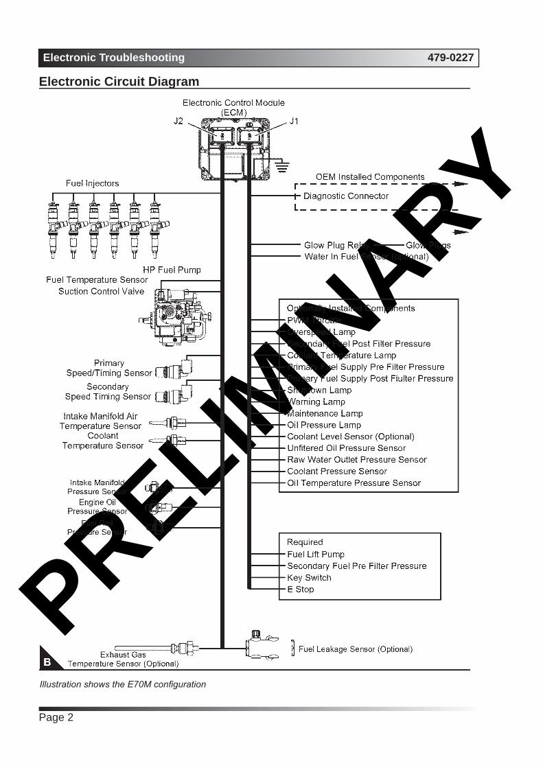
Electronic Circuit Diagram
Illustration shows the E70M configuration

PRELIMIN
ARY479-0227 Electronic Troubleshooting
Page 3
Illustration shows the E44M configuration

PRELIMIN
ARYElectronic Troubleshooting 479-0227
Page 4
Block Diagram
(1). Air cleaner
(2). Air inlet temperature sensor
(3). Exhaust gas temperature sensor (if fuel temperature sensor
(4). Turbocharger
(5). Air-to-air aftercooler
(6). Engine
(7). Coolant temperature sensor
(8). Primary speed/timing sensor
(9). Fuel injectors
(10). Return fuel cooler (optional)
(11). Sea water pressure sensor (if equipped)
(12). Secondary speed/timing sensor
(13). High-pressure fuel pump/transfer pump/fuel temperature sensor
(14). Fuel rail pressure sensor
(15). Pre-filter oil pressure sensor (if equipped)
(16). Post filter oil pressure sensor
(17). Coolant pressure sensor
(18). Oil temperature sensor (if equipped)
(19). Fuel leakage detection sensor (if equipped)
(20). ECM
(21). Electric fuel lift pump
(22). Post-primary fuel filter pressure sensor
(23). Pre-primary fuel filter pressure sensor
(24). Primary fuel filter
(25). Intake manifold pressure sensor
(26). Intake manifold air temperature sensor
(27). Transfer pump inlet regulator
(28). Secondary fuel filter
(29). Fuel tank
(30). Post-secondary fuel filter pressure sensor
(31). Pre-secondary fuel filter pressure sensor

PRELIMIN
ARY479-0227 Electronic Troubleshooting
Page 5
System OperationEngine GovernorThe ECM governs the engine. The ECM determines the timing, the injection pressure, and the amount of fuel that is delivered to each cylinder. These factors are based on the actual conditions and on the desired conditions at any given time during starting and operation.
The desired engine speed is typically determined by one of the following conditions:
• The position of the throttle
• CAN input, set to default
Timing ConsiderationsOnce the governor has determined the amount of fuel that is required, the governor must determine the timing of the fuel injection. Fuel injection timing is determined by the ECM after considering input from the following components:
• Coolant temperature sensor
• Intake manifold air temperature sensor
• Intake manifold pressure sensor
The ECM adjusts timing for optimum engine performance and for fuel economy. Actual timing and desired timing cannot be viewed with the electronic service tool. The ECM determines the location of top centre of the number one cylinder from the signals that are provided by the engine speed/timing sensors. The ECM determines when injection should occur relative to top center. The ECM then provides the signal to the injector at the desired time.
Fuel InjectionThe ECM sends a high voltage signal to the injector solenoids in order to energize the solenoids. By controlling the timing and the duration of the high voltage signal, the ECM can control the following aspects of injection:
• Injection timing
• Fuel delivery
The flash file inside the ECM establishes certain limits on the amount of fuel that can be injected. The “FRC Fuel Limit” is a limit that is based on the intake manifold pressure. The “FRC Fuel Limit” is used to control the air/fuel ratio for control of emissions. When the ECM senses a higher intake manifold
pressure, the ECM increases the “FRC Fuel Limit”. A higher intake manifold pressure indicates that there is more air in the cylinder. When the ECM increases the “FRC Fuel Limit” , the ECM allows more fuel into the cylinder.
The “Rated Fuel Limit” is a limit that is based on the power rating of the engine and on the engine rpm. The “Rated Fuel Limit” is like the rack stops and the torque spring on a mechanically governed engine. The “Rated Fuel Limit” provides the power curves and the torque curves for a specific engine family and a specific engine rating. All of these limits are determined at the factory. These limits cannot be changed.
Customer Parameters and Engine Speed GoverningA unique feature with electronic engines is customer specified parameters. These parameters allow the owner of the machine to fine-tune the ECM for engine operation. Fine-tuning the ECM allows the machine owner to accommodate the typical usage of the machine and the power train of the machine.
Many of the customer parameters provide additional restrictions on the actions that will be performed by the ECM in response to input from the operator.
Some parameters are intended to notify the operator of potential engine damage (engine monitoring parameters). Other parameters are used to enhance the engine installation into the machine. Other parameters are used to provide engine operating information to the owner of the machine.
PRELIMIN
ARYElectronic Troubleshooting 479-0227
Page 6
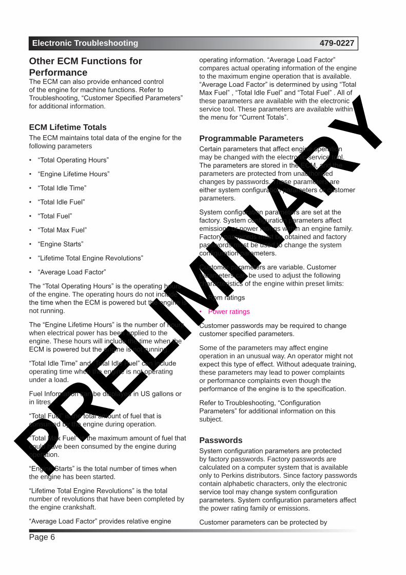
Other ECM Functions for PerformanceThe ECM can also provide enhanced control of the engine for machine functions. Refer to Troubleshooting, “Customer Specified Parameters” for additional information.
ECM Lifetime TotalsThe ECM maintains total data of the engine for the following parameters
• “Total Operating Hours”
• “Engine Lifetime Hours”
• “Total Idle Time”
• “Total Idle Fuel”
• “Total Fuel”
• “Total Max Fuel”
• “Engine Starts”
• “Lifetime Total Engine Revolutions”
• “Average Load Factor”
The “Total Operating Hours” is the operating hours of the engine. The operating hours do not include the time when the ECM is powered but the engine is not running.
The “Engine Lifetime Hours” is the number of hours when electrical power has been applied to the engine. These hours will include the time when the ECM is powered but the engine is not running.
“Total Idle Time” and “Total Idle Fuel” can include operating time when the engine is not operating under a load.
Fuel Information can be displayed in US gallons or in litres.
“Total Fuel” is the total amount of fuel that is consumed by the engine during operation.
“Total Max Fuel” is the maximum amount of fuel that could have been consumed by the engine during operation.
“Engine Starts” is the total number of times when the engine has been started.
“Lifetime Total Engine Revolutions” is the total number of revolutions that have been completed by the engine crankshaft.
“Average Load Factor” provides relative engine
operating information. “Average Load Factor” compares actual operating information of the engine to the maximum engine operation that is available. “Average Load Factor” is determined by using “Total Max Fuel” , “Total Idle Fuel” and “Total Fuel” . All of these parameters are available with the electronic service tool. These parameters are available within the menu for “Current Totals”.
Programmable ParametersCertain parameters that affect engine operation may be changed with the electronic service tool. The parameters are stored in the ECM, and the parameters are protected from unauthorised changes by passwords. These parameters are either system configuration parameters or customer parameters.
System configuration parameters are set at the factory. System configuration parameters affect emissions or power ratings within an engine family. Factory passwords must be obtained and factory passwords must be used to change the system configuration parameters.
Customer parameters are variable. Customer parameters can be used to adjust the following characteristics of the engine within preset limits:
• Rpm ratings
• Power ratings
Customer passwords may be required to change customer specified parameters.
Some of the parameters may affect engine operation in an unusual way. An operator might not expect this type of effect. Without adequate training, these parameters may lead to power complaints or performance complaints even though the performance of the engine is to the specification.
Refer to Troubleshooting, “Configuration Parameters” for additional information on this subject.
PasswordsSystem configuration parameters are protected by factory passwords. Factory passwords are calculated on a computer system that is available only to Perkins distributors. Since factory passwords contain alphabetic characters, only the electronic service tool may change system configuration parameters. System configuration parameters affect the power rating family or emissions.
Customer parameters can be protected by

PRELIMIN
ARY479-0227 Electronic Troubleshooting
Page 7
customer passwords. The customer passwords are programmed by the customer. Factory passwords can be used to change customer passwords if customer passwords are lost.
Refer to Troubleshooting, “Factory Passwords” for additional information on this subject.
GlossaryActive Diagnostic Code – An active diagnostic code alerts the operator or the service technician that an electronic system malfunction is currently present. Refer to the term “Diagnostic Code” in this glossary.
Alternating Current (AC) – Alternating current is an electric current that reverses direction at a regular interval that is reoccurring.
Before Top Centre (BTC) – BTC is the 180 degrees of crankshaft rotation before the piston reaches the top dead centre position in the normal direction of rotation.
Breakout Harness – A breakout harness is a test harness that is designed to connect into the engine harness. This connection allows a normal circuit operation and the connection simultaneously provides a Breakout T in order to measure the signals.
Bypass Circuit – A bypass circuit is a circuit that is used as a substitute circuit for an existing circuit. A bypass circuit is typically used as a test circuit.
CAN Data Link (see also J1939 CAN Data Link) – The CAN Data Link is a serial communications port that is used for communication with other microprocessor-based devices.
Code – Refer to “Diagnostic Trouble Code”.
Communication Adapter Tool – The communication adapter provides a communication link between the ECM and the electronic service tool.
Coolant Temperature Sensor – The coolant temperature sensor detects the engine coolant temperature for all normal operating conditions and for engine monitoring.
Data Link – The data link is a serial communication port that is used for communication with other devices such as the electronic service tool.
Derate – Certain engine conditions will generate event codes. Also, an engine derate may be applied. The map for the engine derate is programmed into the ECM software. The engine derate can be one or more of three types: reduction of rated power, reduction of rated engine speed and reduction of
rated machine speed for OEM products.
Desired Engine Speed – The desired engine speed is input to the electronic governor within the ECM. The electronic governor uses the signal from the throttle position sensor, the engine speed/timing sensor, and other sensors in order to determine the desired engine speed.
Diagnostic Trouble Code – A diagnostic trouble code is sometimes referred to as a fault code. These codes indicate an electronic system malfunction.
Diagnostic Lamp – The diagnostic lamp is also called the warning lamp. The diagnostic lamp is used to warn the operator of the presence of an active diagnostic code. The lamp may not be included in all applications.
Digital Sensor Return – The common line (ground) from the ECM is used as ground for the digital sensors.
Digital Sensors – Digital sensors produce a pulse width modulated signal. Digital sensors are supplied with power from the ECM.
Digital Sensor Supply – The power supply for the digital sensors is provided by the ECM.
Direct Current (DC) – Direct current is the type of current that flows consistently in only one direction.
DT, DT Connector, or Deutsch DT – This connector is a type that is used on this engine. The connectors are manufactured by Deutsch .
Duty Cycle – Refer to “Pulse Width Modulation” .
Electronic Engine Control – The electronic engine control is a complete electronic system. The electronic engine control monitors the engine operation under all conditions. The electronic engine control also controls the engine operation under all conditions.
Electronic Control Module (ECM) – The ECM is the control computer of the engine. The ECM provides power to the electronics. The ECM monitors data that is input from the sensors of the engine. The ECM acts as a governor in order to control the speed and the power of the engine.
Electronic Service Tool – The electronic service tool allows a computer (PC) to communicate with the ECM.
Engine Monitoring – Engine Monitoring is the part of the electronic engine control that monitors the sensors. Engine monitoring also warns the operator of detected faults.

PRELIMIN
ARYElectronic Troubleshooting 479-0227
Page 8
Engine Oil Pressure Sensor – The engine oil pressure sensor measures engine oil pressure. The sensor sends a signal to the ECM that is dependent on the engine oil pressure.
Engine Speed/Timing Sensor – An engine speed/ timing sensor is a hall effect switch that provides a digital signal to the ECM. The ECM interprets this signal as the crankshaft position and the engine speed. Two sensors are used to provide the speed and timing signals to the ECM. The primary sensor is associated with the crankshaft and the secondary sensor is associated with the camshaft.
Event Code – An event code may be activated in order to indicate an abnormal engine operating condition. These codes usually indicate a mechanical problem instead of an electrical system problem.
Failure Mode Identifier (FMI) – This identifier indicates the type of failure that is associated with the component. The FMI has been adopted from the SAE practice of J1587 diagnostics. The FMI follows the parameter identifier (PID) in the descriptions of the fault code. The descriptions of the FMIs are in the following list.
0. The data is valid but the data is above the normal operational range.
1. The data is valid but the data is below the normal operational range.
2. The data is erratic, intermittent, or incorrect.
3. The voltage is above normal or the voltage is shorted high.
4. The voltage is below normal or the voltage is shorted low.
5. The current is below normal or the circuit is open.
6. The current is above normal or the circuit is grounded.
7. The mechanical system is not responding properly.
8. There is an abnormal frequency, an abnormal pulse width, or an abnormal time period.
9. There has been an abnormal update.
10. There is an abnormal rate of change.
11. The failure mode is not identifiable.
12. The device or the component is damaged.
13. The device requires calibration.
14. There is a special instruction for the device.
15. The signal from the device is high (least severe).
16. The signal from the device is high (moderate severity).
17. The signal from the device is low (least severe).
18. The signal from the device is low (moderate severity).
19. There is an error in the data from the device.
31.Condition exists.
Flash File – This file is software that is inside the ECM. The file contains all the instructions (software) for the ECM and the file contains the performance maps for a specific engine. The file may be reprogrammed through flash programming.
Flash Programming – Flash programming is the method of programming or updating an ECM with an electronic service tool over the data link instead of replacing components.
FRC – See “Fuel Ratio Control” .
Fuel Pump – See “High Pressure Fuel Pump” .
Fuel Rail – This item is sometimes referred to as the High Pressure Fuel Rail. The fuel rail supplies fuel to the electronic unit injectors. The high-pressure fuel pump and the fuel rail pressure sensor work with the ECM in order to maintain the desired fuel pressure in the fuel rail. This pressure is determined by calibration of the engine in order to enable the engine to meet emissions and performance requirements.
Fuel Rail Pressure Sensor – The fuel rail pressure sensor sends a signal to the ECM that is dependent on the pressure of the fuel in the fuel rail.
Fuel Ratio Control (FRC) – The FRC is a limit that is based on the control of the ratio of the fuel to air. The FRC is used for purposes of emission control. When the ECM senses a higher intake manifold air pressure, the FRC increases the FRC Limit.
Full Load Setting (FLS) – The FLS is the parameter that represents the fuel system adjustment. This adjustment is made at the factory in order to fine-tune the fuel system. This parameter must be programmed.
Full Torque Setting (FTS) – The FTS is the parameter that represents the adjustment for the engine torque. This adjustment is made at the factory in order to fine-tune the fuel system. This

PRELIMIN
ARY479-0227 Electronic Troubleshooting
Page 9
adjustment is made with the FLS. This parameter must be programmed.
Glow Plug – The glow plug is an optional starting aid for cold conditions. One glow plug is installed in each combustion chamber in order to improve the ability of the engine to start. The ECM uses information from the engine sensors such as the coolant temperature to determine when the glow plug relay must provide power to each glow plug. Each of the glow plugs then provides a hot surface in the combustion chamber in order to vaporize the mixture of air and fuel. The result is improved ignition during the compression stroke of the cylinder.
Glow Plug Relay – The glow plug relay is controlled by the ECM in order to provide high current to the glow plugs that are used in the starting aid system.
Harness – The harness is the bundle of wiring (loom) that connects all components of the electronic system.
Hertz (Hz) – Hertz is the measure of electrical frequency in cycles per second.
High Pressure Fuel Pump – The pump supplies fuel under pressure to the fuel rail (high-pressure fuel rail).
High Pressure Fuel Rail – See “Fuel Rail” .
Injector Codes – Injector codes contain 30 characters. The codes are supplied with new injectors. The code is input through the electronic service tool into the ECM. The injector codes compensate for manufacturing tolerances of the injector and for variances over the life of the injector.
Intake Manifold Air Temperature Sensor – The intake manifold air temperature sensor detects the air temperature in the intake manifold. The ECM monitors the air temperature and other data in the intake manifold in order to adjust injection timing and other performance functions.
Intake Manifold Pressure Sensor – The Intake Manifold Pressure Sensor measures the pressure in the intake manifold. The pressure in the intake manifold may be different to the pressure outside the engine (atmospheric pressure). The difference in pressure may be caused by an increase in air pressure by a turbocharger (if equipped).
J1939 CAN Data Link – This data link is a SAE standard diagnostic communications data link that is used to communicate between the ECM and other electronic devices.
Logged Diagnostic Codes – Logged diagnostic codes are codes which are stored in the memory. These codes are an indicator of possible causes for intermittent problems. Refer to the term “Diagnostic Trouble Codes” for more information.
NOx Reduction System – The NOx Reduction System recycles a portion of the exhaust gases back into the inlet air in order to reduce the oxides of nitrogen (NOx) in the exhaust gases. The recycled exhaust gas passes through a cooler before being introduced into the inlet air.
OEM – OEM is an abbreviation for the Original Equipment Manufacturer. The OEM is the manufacturer of the machine or the vehicle that uses the engine.
Open Circuit – An open circuit is a condition that is caused by an open switch, or by an electrical wire or a connection that is broken. When this condition exists, the signal or the supply voltage can no longer reach the intended destination.
Parameter – A parameter is a value or a limit that is programmable. The parameters help determine specific characteristics or behaviors of the engine.
Password – A password is a group of numeric characters or a group of alphanumeric characters that is designed to restrict access to parameters. The electronic system requires correct passwords in order to change some parameters (Factory Passwords). Refer to Troubleshooting, “Factory Passwords” for more information.
Personality Module – See “Flash File”
Power Cycling – Power cycling refers to the action of cycling the keyswitch from any position to the OFF position, and to the START/RUN position.
Pressure Limiting Valve (PLV) – The PLV is a valve in the fuel rail that prevents excessive pressure. The PLV will reduce the pressure to a safe level that will limit engine operation but the reduced pressure will not stop the engine.
Primary Speed/Timing Sensor – This sensor determines the position of the crankshaft during engine operation. If the primary speed/timing sensor fails during engine operation, the secondary speed/ timing sensor is used to provide the signal.
Pulse Width Modulation (PWM) – The PWM is a signal that consists of pulses that are of variable width. These pulses occur at fixed intervals. The ratio of “TIME ON” versus “TIME OFF” can be varied. This ratio is also referred to as a duty cycle.

PRELIMIN
ARYElectronic Troubleshooting 479-0227
Page 10
Rated Fuel Limit – This limit is based on the power rating of the engine and on the engine rpm. The Rated Fuel Limit enables the engine power and torque outputs to conform to the power and torque curves of a specific engine model. These limits are in the flash file and these limits cannot be changed.
Reference Voltage – Reference voltage is a regulated voltage and a steady voltage that is supplied by the ECM to a sensor. The reference voltage is used by the sensor to generate a signal voltage.
Relay – A relay is an electromechanical switch. A flow of electricity in one circuit is used to control the flow of electricity in another circuit. A small current or voltage is applied to a relay in order to switch a much larger current or voltage.
Secondary Speed/Timing Sensor – This sensor determines the position of the camshaft during engine operation. If the primary speed/timing sensor fails during engine operation, the secondary speed/timing sensor is used to provide the signal.
Sensor – A sensor is a device that is used to detect the current value of pressure or temperature, or mechanical movement. The information that is detected is converted into an electrical signal.
Short Circuit – A short circuit is a condition that has an electrical circuit that is inadvertently connected to an undesirable point. An example of a short circuit is a wire which rubs against a vehicle frame and this rubbing eventually wears off the wire insulation. Electrical contact with the frame is made and a short circuit is created.
Signal – The signal is a voltage or a waveform that is used in order to transmit information typically from
a sensor to the ECM.
Suction Control Valve (SCV) – The SCV is a control device in the high-pressure fuel pump. The ECM controls the pressure in the fuel rail by using the SCV to control the amount of fuel that enters the chambers in the pump.
Supply Voltage – The supply voltage is a continuous voltage that is supplied to a component in order to provide the electrical power that is required for the component to operate. The power may be generated by the ECM or the power may be battery voltage that is supplied by the engine wiring.
Suspect Parameter Number (SPN) – The SPN is a J1939 number that identifies the specific component of the electronic control system that has experienced a diagnostic code.
System Configuration Parameters – System configuration parameters are parameters that affect emissions and/or operating characteristics of the engine.
Tattletale – Certain parameters that affect the operation of the engine are stored in the ECM. These parameters can be changed by use of the electronic service tool. The tattletale logs the number of changes that have been made to the parameter. The tattletale is stored in the ECM.
Throttle Position – The throttle position is the interpretation by the ECM of the signal from the throttle position sensor or the throttle switch.
Throttle Position Sensor – The throttle position sensor is a sensor that is connected to a throttle device such as an accelerator pedal or a hand lever. This sensor sends a signal to the ECM that is used to calculate desired engine speed.
Throttle Switch – The throttle switch sends a signal to the ECM that is used to calculate desired engine speed.
Top Center Position – The top center position refers to the crankshaft position when the engine piston position is at the highest point of travel. The engine must be turned in the normal direction of rotation in order to reach this point.
Total Tattletale – The total tattletale is the total number of changes to all the parameters that are stored in the ECM.
Wastegate – The wastegate is a device in a turbocharged engine that controls the maximum boost pressure that is provided to the inlet manifold.
Wastegate Regulator – The wastegate regulator
PRELIMIN
ARY479-0227 Electronic Troubleshooting
Page 11
controls the pressure in the intake manifold to a value that is determined by the ECM. The wastegate regulator provides the interface between the ECM and the wastegate.
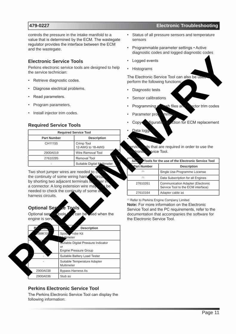
Electronic Service ToolsPerkins electronic service tools are designed to help the service technician:
• Retrieve diagnostic codes.
• Diagnose electrical problems.
• Read parameters.
• Program parameters.
• Install injector trim codes.
Required Service ToolsRequired Service Tool
Part Number DescriptionCH11155 Crimp Tool
12-AWG to 18-AWG
2900A019 Wire Removal Tool
27610285 Removal Tool
- Suitable Digital Multimeter
Two short jumper wires are needed to check the continuity of some wiring harness circuits by shorting two adjacent terminals together in a connector. A long extension wire may also be needed to check the continuity of some wiring harness circuits.
Optional Service ToolsOptional service tools that can be used when the engine is serviced.
Part Number DescriptionU5MK1092 Spoon Probe Kit
Multimeter
-or-
Suitable Digital Pressure IndicatororEngine Pressure Group
- Suitable Battery Load Tester
- Suitable Temperature AdapterMultimeter
2900A038 Bypass Harness As
2900A036 Stub as
Perkins Electronic Service ToolThe Perkins Electronic Service Tool can display the following information:
• Status of all pressure sensors and temperature sensors
• Programmable parameter settings • Active diagnostic codes and logged diagnostic codes
• Logged events
• Histograms
The Electronic Service Tool can also be used to perform the following functions:
• Diagnostic tests
• Sensor calibrations
• Programming of flash files and injector trim codes
• Parameter programming
• Copy configuration function for ECM replacement
• Data logging
• Graphs (real time)
Service tools that are required in order to use the Electronic Service Tool.
Service Tools for the use of the Electronic Service ToolPart Number Description
(1) Single Use Programme Locense(1) Data Subscription for all Engines
27610261 Communication Adapter (Electronic Service Tool to the ECM interface)
27610164 Adapter cable as
(1) Refer to Perkins Engine Company LimitedNote: For more information on the Electronic Service Tool and the PC requirements, refer to the documentation that accompanies the software for the Electronic Service Tool.

PRELIMIN
ARYElectronic Troubleshooting 479-0227
Page 12
Connecting the Electronic Service Tool and the Communication Adapter II
(1). Personal Computer (PC)
(2). Adapter Cable (Computer Serial Port)
(3). Communication Adapter II
(4). Adapter Cable Assembly
Note: Items (2), (3) and (4) are part of the Communication Adapter II kit.
Use the following procedure in order to connect the Electronic Service Tool and the Communication Adapter II.
1. Turn the keyswitch to the OFF position.
2. Connect cable (2) between the “COMPUTER” end of communication adapter (3) and the RS232 serial port of PC (1).
Note: The Adapter Cable Assembly(4) is required to connect to the USB port on computers that are not equipped with an RS232 serial port.
3. Connect cable (4) between the “DATA LINK” end of communication adapter (3) and the service tool connector.
4. Place the keyswitch in the ON position. If the Electronic Service Tool and the communication adapter do not communicate with the Electronic Control Module (ECM), refer to the diagnostic procedure Troubleshooting, “Electronic Service Tool DoesNot Communicate”.
Indicator OutputsSix lamps are possible as outputs. The following lamps will normally be installed in a typical installation, (customer to supply).
• Shutdown.
• Warning.
• Overspeed.
• Coolant temperature.
• Oil pressure.
• Maintenance.
Functions of lamp outputsShutdownLamp check - When the keyswitch is turned to ON, the lamp will come on for 5 seconds. The lamp will then go off unless there is an active warning.
Flashing - The lamp will be flashing when the engine is derated because of an active diagnostic code. An example of an active code is ‘System Voltage High’.
On - The lamp will be on when the shutdown level in the engine protection strategy has been reached. The ‘Warning’ lamp will also be on.
Warning LampLamp check - When the keyswitch is turned to ON, the lamp will come on for come on for 5 seconds. The lamp will then go off unless there is an active warning.
Flashing - The lamp will be flashing when a ‘warning’ or a ‘warning and derate’ is active. This situation includes low oil pressure.
On - The lamp will be on when the shutdown level has been reached. The ‘Shutdown’ lamp will also be on.
Lamp CheckLamp check - When the keyswitch is turned ON, the lamp will come on for 2 seconds. The lamp will then go off unless there is an actice warning.
Replacing the ECMNOTICE
Care must be taken to ensure that fluids are contained during performance of inspection, maintenance, testing, adjusting and repair of the

PRELIMIN
ARY479-0227 Electronic Troubleshooting
Page 13
product. Be prepared to collect the fluid with suitable containers before opening any compartment or disassembling any component containing fluids.
Dispose of all fluids according to local regulations and mandates.
NOTICE
Keep all parts clean from contaminants.
Contaminants may cause rapid wear and shortened component life.
The engine is equipped with an Electronic Control Module (ECM). The ECM contains no moving parts. Follow the troubleshooting procedures in this manual in order to be sure that replacing the ECM will correct the fault. Verify that the suspect ECM is the cause of the fault.
Note: Ensure that the ECM is receiving power and that the ECM is properly grounded before replacement of the ECM is attempted. Refer to the schematic diagram.
A test ECM can be used in order to determine if the ECM on the engine is faulty. Install a test ECM in place of the suspect ECM. Install the flash file with the correct part number into the test ECM. Program the parameters for the test ECM. The parameters must match the parameters in the suspect ECM. Refer to the following test steps for details. If the test ECM resolves the fault, reconnect the suspect ECM. Verify that the fault returns. If the fault returns, replace the ECM.
Note: If an ECM is used as a test ECM, select “Test ECM Mode” on the electronic service tool before the engine serial number is entered.
Use the electronic service tool to read the parameters in the suspect ECM. Record the parameters in the suspect ECM. Install the flash file into the new ECM. After the ECM is installed on the engine, the parameters must be programmed into the new ECM.
Note: When a new ECM is not available, an ECM can be used from an engine that is not in service. The ECM must have the same serial number suffix. Ensure that the replacement ECM and the part number for the flash file match the suspect ECM. Be sure to record the parameters from the replacement ECM. Use the “Copy Configuration ECM
Replacement” function in the electronic service tool.
NOTICE
If the flash file and engine application are not matched, engine damage may result.
Perform the following procedure in order to replace the ECM.
1. Connect the electronic service tool to the diagnostic connector.
2. Use the “Copy Configuration ECM Replacement” function from the electronic service tool. If the “Copy Configuration” is successful, proceed to Step 4. If the “Copy Configuration” failed, proceed to Step 3.
Note: Record any Logged Faults and Events for your records.
3. Record the following parameters:
• Record all of the parameters on the “Configuration” screen.
• Record all of the parameters on the “Throttle Configuration” screen.
• Record all of the parameters on the “Mode Configuration” screen.
• Record the serial numbers of the electronic unit injectors. The injector serial numbers are shown on the “Injector Trim Calibration” screen.
Note: If the parameters cannot be read, the parameters must be obtained elsewhere. Some parameters are stamped on the engine information plate, but most parameters must be obtained from the TMI data on the Perkins secured web site.
4. Remove power from the ECM.
5. Remove the ECM. Refer to Disassembly and Assembly, “Electronic Control Module - Remove and Install”.
6. Install the replacement ECM. Refer to Disassembly and Assembly, “Electronic Control Module - Remove and Install”.
7. If the replacement ECM is used as a test ECM, select “Test ECM Mode” on the electronic service tool.
8. Download the flash file.
a. Connect the electronic service tool to the diagnostic connector.
b. Select ‘WinFlash’ from the ‘Utilities’ menu of the electronic service tool.

PRELIMIN
ARYElectronic Troubleshooting 479-0227
Page 14
c. Select the downloaded flash file.
9. If necessary, use the electronic service tool to clear the rating interlock . To clear the rating interlock, enter the factory password when the electronic service tool is first connected. Activating the Test ECM mode will also clear the rating interlock .
10. Use the electronic service tool to program the parameters. Perform the following procedure.
a. If the “Copy Configuration” procedure was successful, use the “Copy Configuration, ECM Replacement” function to load the configuration file into the ECM.
Note: During the following procedure, factory passwords may be required.
b. If the “Copy Configuration” procedure failed, configure the parameters individually. The parameters should match the parameters from step 3.
Perform the “Fuel System Verification Test” .
11. Check for logged diagnostic codes. Factory passwords are required to clear logged events.
Self-DiagnosticsThe Electronic Control Module (ECM) can detect faults in the electronic system and with engine operation. A self-diagnostic check is also performed whenever power is applied to the ECM.
When a fault is detected, a diagnostic trouble code is generated. This code conforms to the SAE J1939 standard. An alarm may also be generated.
Diagnostic Trouble Code – When a fault in the electronic system is detected, the ECM generates a diagnostic trouble code. The diagnostic trouble code indicates the specific fault in the circuitry.
Diagnostic codes can have two different states:
• Active
• Logged
Active Code – An active diagnostic code indicates that an active fault has been detected by the control system. Active codes require immediate attention.
Always service active codes prior to servicing logged codes.
Logged Code – Many generated codes are stored in the permanent memory of the ECM. The codes are logged for 100 operating hours unless a code is
cleared by use of the electronic service tool.
Logged codes may not indicate that a repair is needed. The fault may have been temporary. The fault may have been resolved since the logging of the code. If the system is powered, an active diagnostic trouble code may be generated whenever a component is disconnected. When the component is reconnected, the code is no longer active. Logged codes may be useful to help troubleshoot intermittent faults. Logged codes can also be used to review the performance of the engine and the electronic system.
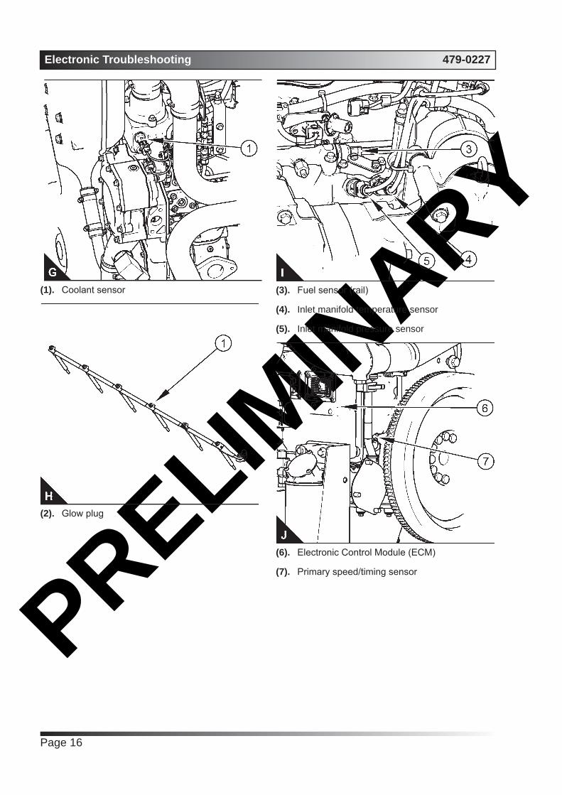
Sensors and Electrical ConnectorsThe Electronic Control Module (ECM) and most of the engine sensors are located on the left side of the engine. For the remaining sensors that are attached to the engine, see the following illustrations.
Note: In the following illustrations, some components have been removed in order to improve visibility.

PRELIMIN
ARY479-0227 Electronic Troubleshooting
Page 15
Sensor locations on the left side of the engine(1). Coolant temperature sensor
(2). Glow plug
(3). Fuel pressure sensor (rail)
(4). Inlet manifold temperature sensor
(5). Inlet manifold pressure sensor
(6). Electronic Control Module (ECM)
(7). Primary speed/timing sensor
(8). Electric priming/lift pump
(9). Low pressure fuel sensor
(10). Oil pressure sensor
(11). Solenoid for high pressure fuel pump
(12). Fuel temperature sensor
PRELIMIN
ARYElectronic Troubleshooting 479-0227
Page 16
(1). Coolant sensor
(2). Glow plug
(3). Fuel sensor (rail)
(4). Inlet manifold temperature sensor
(5). Inlet manifold pressure sensor
(6). Electronic Control Module (ECM)
(7). Primary speed/timing sensor

PRELIMIN
ARY479-0227 Electronic Troubleshooting
Page 17
(8). Low pressure fuel sensor
(9). Electric priming/lift pump
(10). Oil pressure sensor
(11). Solenoid for high pressure fuel pump
(12). Fuel temperature sensor
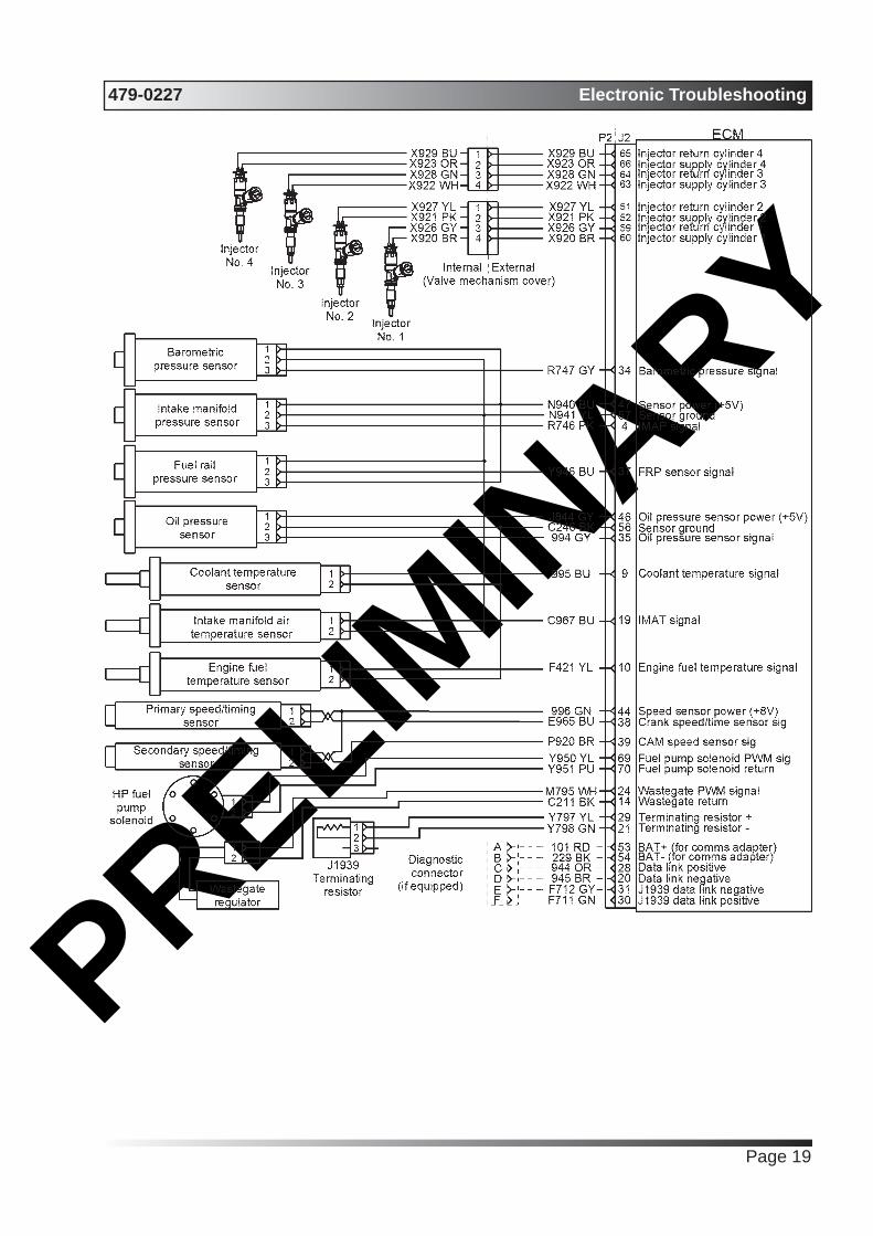
Engine Wiring InformationHarness Wire IdentificationPerkins identifies all wires with 11 solid colors. The circuit number is stamped on the wire at a 25 mm (1 inch) spacing. The table lists the wire colors and the color codes.
Colour Codes for the Harness WireColour Code Colour
BK Black
BR Brown
RD Red
OR Orange
YL Yellow
GN Green
BU Blue
PU Purple
GY Grey
WH White
PK Pink
For example, a wire identification of X925-PK(Pink) on the schematic would signify a pink wire with the circuit number X925. X925-PK(Pink) identifies the power supply for the No. 1 injector.
Note: Always replace a harness wire with the same gauge of wire and with the same color code.
Note: In the following diagrams, “Px” signifies a plug and “Jx” signifies a jack.

PRELIMIN
ARYElectronic Troubleshooting 479-0227
Page 18
Schematic diagram of the 6 cyclinder engine connections to the J2 connector on the ECM
PRELIMIN
ARY479-0227 Electronic Troubleshooting
Page 19
PRELIMIN
ARYElectronic Troubleshooting 479-0227
Page 20
ECM Harness Connector TerminalsThe Electronic Control Module (ECM) uses connectors that have 70 terminals to interface to the wiring harness. A more in depth explanation of the connector can be found in the Users Handbook & Installation Information manual.

PRELIMIN
ARY479-0227 Programming Parameters
Page 21
Programming Parameters
Programming ParametersThe electronic service tool can be used to view certain parameters that can affect the operation of the engine. The electronic service tool can also be used to change certain parameters. The parameters are stored in the Electronic Control Module (ECM). Some of the parameters are protected from unauthorized changes by passwords. Parameters that can be changed have a tattletale number. The tattletale number is incremented whenever a parameter is changed.
Test ECM Mode“Test ECM Mode” is a feature in the software that can be used to help troubleshoot an engine that may have a fault in the Electronic Control Module (ECM). This feature allows a standard ECM to be used as a test ECM. This feature eliminates the need to stock a test ECM.
1. Search for the latest flash file for the engine.
Note: If a newer software version is available for the engine, install the newest software on the suspect ECM. If the new software does not eliminate the fault, continue with this procedure.
2. Use the “Copy Configuration” feature on the electronic service tool to copy the parameters from the suspect ECM.
Note: If the “ECM Replacement” feature cannot be used, record the programmed values into the “Customer Specified Parameters Worksheet”. Also record the system configuration parameters.
3. Disconnect the suspect ECM. Temporarily connect the test ECM to the engine. Do not mount the test ECM on the engine.
4. Flash program the test ECM with the newest software that is available.
5. Start the “Test ECM Mode” on the electronic service tool. Access the feature through the “Service” menu. The electronic service tool will display the status of the test ECM and the hours that are remaining for the “Test ECM Mode” .
Note: “Test ECM Mode” can only be activated if the engine serial number has not already been programmed during normal operation of the ECM. If the engine serial number is programmed and the ECM is not in “Test ECM Mode” , the ECM can never be used as a test ECM.
6. Use the “Copy Configuration” feature on the electronic service tool to program the test ECM.
Note: If the “ECM Replacement” feature cannot be used, program the test ECM with the values from the “Customer Specified Parameters Worksheet” and the values from the System Configuration Parameters.
7. Program the engine serial number into the test ECM.
Note: The “Test ECM Mode” must be activated before the engine serial number is programmed into the ECM.
8. Verify that the test ECM eliminates the fault. When the “Test ECM Mode” is activated, an internal timer sets a 24 hour clock. This clock will count down only while the ECM is powered and the keyswitch is in the ON position. After the ECM has counted down the 24 hour period, the ECM will exit the “Test ECM Mode” . The parameters and the engine serial number will be set.
If the test ECM eliminates the fault, the engine can be released while the “Test ECM Mode” is still active.
Once an ECM has been activated in the “Test ECM Mode” , the ECM will stay in the “Test ECM Mode” until the timer times out. If the ECM is used as a test ECM for more than one engine, the “Test ECM Mode” must be reactivated. Anytime prior to the “Test ECM Mode” timing out, the ECM can be reset to 24 hours.
Factory PasswordsNOTICE
Operating the engine with a flash file not designed for that engine will damage the engine. Be sure the flash file is correct for your engine.
Note: Factory passwords are provided only to Perkins authorized distributors.
Factory passwords are required to perform each of the following functions:
Program a new Electronic Control Module (ECM).When an ECM is replaced, the system configuration parameters must be programmed into the new ECM. A new ECM will allow these parameters to be programmed once without factory passwords.

PRELIMIN
ARYProgramming Parameters 479-0227
Page 22
After the initial programming, some parameters are protected by factory passwords.
Rerate the engine.Rerating the engine may require changing the interlock code, which is protected by factory passwords.
Unlock parameters.Factory passwords are required in order to unlock certain system configuration parameters. Refer to Troubleshooting, “System Configuration Parameters”.
Clear engine events and certain diagnostic trouble codes.Most engine events require factory passwords in order to clear the code from ECM memory. Clear these codes only when you are certain that the fault has been corrected. For example, the 190- 15 Engine Overspeed requires the use of factory passwords in order to clear the code from ECM memory.
Since factory passwords contain alphabetic characters, the electronic service tool must be used to perform these functions. In order to obtain factory passwords, proceed as if you already have the password. If factory passwords are needed, the electronic service tool will request the factory passwords. The electronic service tool will display the information that is required to obtain the passwords.
Flash ProgrammingFlash Programming – A method of loading a flash file into the Electronic Control Module (ECM)
The electronic service tool is used to flash program a flash file into the ECM. The flash programming transfers the flash file from the PC to the ECM.
Flash Programming a Flash File1. Obtain the part number for the new flash file.
Note: If you do not have the part number for the flash file, use “PTMI” on the Perkins secured web site.
Note: You must have the engine serial number in order to search for the part number of the flash file.
2. Connect the electronic service tool to the diagnostic connector.
3. Turn the keyswitch to the ON position. Do not start the engine.
4. Select “WinFlash” from the “Utilities” menu on the electronic service tool.
Note: If “WinFlash” will not communicate with the ECM, refer to Troubleshooting, “Electronic Service Tool Does Not Communicate”.
5. Flash program the flash file into the ECM.
a. Select the engine ECM under the “Detected ECMs” .
b. Press the “Browse” button in order to select the part number of the flash file that will be programmed into the ECM.
c. When the correct flash file is selected, press the “Open” button.
d. Verify that the “File Values” match the application. If the “File Values” do not match the application, search for the correct flash file.
e. When the correct flash file is selected, press the “Begin Flash” button.
f. The electronic service tool will indicate when flash programming has been successfully completed.
6. Use the electronic service tool to check for diagnostic code 631-2. If this diagnostic code is active and the flash file is not being installed in order to change the engine rating, repeat this procedure from 1. If this diagnostic code is active and the flash file is being installed in order to change the engine rating, factory passwords must be obtained before the flash file will be accepted.
7. Access the “Configuration” screen under the “Service” menu in order to determine the parameters that require programming. Look under the “Tattletale” column. All of the parameters should have a tattletale of 1 or more. If a parameter has a tattletale of 0, program that parameter.
8. Start the engine and check for proper operation. Check that there are no active diagnostic codes.
“WinFlash” Error MessagesIf any error messages are displayed during flash programming, click on the “Cancel” button in order to stop the process. Access the information about the “ECM Summary” under the “Information” menu.

PRELIMIN
ARY479-0227 Programming Parameters
Page 23
Ensure that you are programming the correct flash file for your engine.
If a 630-2 diagnostic trouble code is displayed after flash programming, a required parameter is missing. Program the missing parameter.
Injector Code - CalibrateInjector codes are codes that are 30 hexadecimal characters in length that are supplied with each injector. The code is on a plate on the top of the injector and a card is also included in the packaging for the injector. The code is used by the Electronic Control Module (ECM) to balance the performance of the injectors.
Illustration (A) shows the label with the injector code.
Sequence for recording the injector code
The electronic service tool is used to load the injector codes into the ECM.
The injector codes must be loaded into the ECM if any of the following conditions occur:
• An electronic unit injector is replaced.
• The ECM is replaced.
• Diagnostic code 630-2 is active.
• Electronic injectors are exchanged between cylinders.
Note: Diagnostic code 630-2 will also become active if the engine serial number, FLS or FTS are not entered into the ECM.
If the ECM is replaced, the injector codes are normally transferred to the new ECM as part of the “Copy Configuration” procedure. If the “Copy Configuration” procedure fails, the injector codes must be loaded manually.
Installing Injector CodesNote: The injector code is located on the electronic unit injector.
1. Record the injector code for each electronic unit injector.
2. Connect the electronic service tool to the diagnostic connector. Refer to Troubleshooting, “Electronic Service Tools”.
3. Turn the keyswitch to the ON position.
4. Select the following menu options on the electronic service tool:
• Service
• Calibrations
• Injector Trim Calibration
5. Select the appropriate cylinder.
6. Click on the “Change” button.
7. Input the applicable injector code that was recorded in Test Step 1.
8. Click on the “OK” button.
The injector code is loaded into the ECM.
9. Repeat the procedure for each cylinder, as required.

PRELIMIN
ARYProgramming Parameters 479-0227
Page 24
Exchanging Electronic Unit InjectorsExchanging electronic unit injectors can help determine if a combustion problem is in the electronic unit injector or in the cylinder. If two electronic unit injectors that are currently installed in the engine are exchanged between cylinders, the injector codes must also be exchanged. Press the “Exchange” button at the bottom of the “Injector Trim Calibration” screen on the electronic service tool. Select the two electronic unit injectors that will be exchanged and press the “OK” button. The tattletale for the electronic unit injectors that were exchanged will increase by one.
Rating NumberThis parameter is the engine rating that is used by the Electronic Control Module (ECM) for the maximum power of the engine.
Range Default Factory Password1 to the maximum number of ratings
in the currently installed Flash File
1 Yes
Throttle 1 Droop PercentageThis parameter represents the amount of droop that is applied to the “Throttle 1” input.
Range Default Factory Password0 to 10 percent 5.0% No
Throttle 2 Droop PercentageThis parameter represents the amount of droop that is applied to the “Throttle 2” input.
Range Default Factory Password0 to 10 percent 5.0% No
TSC1 Droop PercentageThis parameter represents the amount of droop that is applied to the “Torque Speed Control 1(TSC1)” input.
Range Default Factory Password0 to 10 percent 5.0% No
Throttle SetupThere are two separate channels for throttle input. The two channels can have any combination of a digital throttle that uses a Pulse Width Modulated (PWM) signal, an analog throttle or a multi-position switched throttle.
The Electronic Control Module (ECM) must be programmed with the type of throttle input that is being used in either position. From the menu, select “Services” . On the “Services” screen, select “Throttle Configuration” . Select the type of throttle from the following list:
• No throttle
• Analog throttle
• PWM throttle
• Multi-position throttle switch
The Electronic Control Module (ECM) must be programmed for throttle arbitration. This parameter determines which throttle input has priority. From the menu, select “Services” . On the “Services” screen, select “Throttle Arbitration” . Select the arbitration method from the following list:
• Highest Wins
• Lowest Wins
• Manual Switch
The default setting for throttle arbitration is “Highest Wins” .

PRELIMIN
ARY479-0227 Customer Specified Parameters
Page 25
Customer Specified Parameters
Customer Specified ParametersCustomer specified parameters allow the engine to be configured to the exact needs of the application.
Customer parameters may be changed repeatedly as operational requirements change.
ECM Identification ParameterEquipment ID“Equipment ID” is the identification of the equipment that is assigned by the customer. The “Equipment ID” is only for reference by the customer. The “Equipment ID” is not required by the Electronic Control Module (ECM).
Value Default17 digits
The available characters are dependent on the service tool
that is being used.
Not programmed
Engine Rating ParameterRating NumberThe rating number is the selected rating within a power rating family. The flash file defines the power rating family. The flash file can contain one to four ratings. The rating number defines the power rating that is used within the power rating family.
Minimum Maximum Default1 4 1
Cooldown Delay Time Value Default
1 to 60 minutes 5 minutes
Multiple Engines on J1939Engine LocationIn a situation where multiple engines communicate on one J1939 channel, the Engine Location parameter defines the identity of each engine in the set.
Value DefaultEngine #1Engine #2Engine #3Engine #4Engine #5
Engine #1
Configurable InputsCoolant Level SwitchA coolant level sensor is an optional switch input. Programming the “Coolant Level Switch” parameter to “Enabled” notifies the ECM that a coolant level switch input is present. If this parameter is programmed to “Enabled” and the coolant level falls below the measured level, a “111-1” diagnostic code will be displayed.
Value DefaultInstalled
Not InstalledNot Installed
User-Defined Switch Installation StatusA user-defined shutdown switch is an optional switch input. Programming the “User Defined Switch Installation Status” parameter to “Enabled” notifies the ECM that a user-defined switch input is present. If this parameter is programmed to “Enabled” and the user-defined shutdown switch closes, the engine will shut down.
Value DefaultInstalled
Not InstalledNot Installed
Auxiliary Pressure Sensor Installation StatusAn auxiliary pressure sensor is an optional input. Programming the “Auxiliary Pressure Sensor Installation Status” parameter to “Enabled” notifies the ECM that an auxiliary pressure sensor input is present.
Fuel Filter Differential Pressure Switch ConfigurationA fuel filter differential pressure switch is an optional input. Programming the switch configuration parameter to “Normally Open” or “Normally Closed” notifies the ECM that a fuel filter differential pressure switch input is present.

PRELIMIN
ARYCustomer Specified Parameters 479-0227
Page 26
Value DefaultNot Installed
Normally OpenNormally Closed
Not Installed
System SettingsCaution: Engine electrical components are specific to voltage.
System Operating Voltage ConfigurationThe System Operating Voltage Configuration parameter is the operating voltage for the engine electrical system.
Value Default12 VDC24 VDC
24 VDC
PasswordsCustomer Password 1The Customer Password 1 is the first security password that can be defined by the customer.
Value DefaultEight alphanumeric characters Eight spaces
Customer Password 2The Customer Password 2 is the second security password that can be defined by the customer.
Value DefaultEight alphanumeric characters Eight spaces
Security Access ParametersCAN Communication Protocol Write SecurityThe CAN Communication Protocol Write Security parameter control the security required for writing information through the CAN bus.
Value DefaultSeed and Key No Security Seed and Key
CAN Communication Protocol Read SecurityThe CAN Communication Protocol Read Security parameter control the security required for reading information from the CAN bus.
Value DefaultSeed and Key No Security Seed and Key
PRELIMIN
ARY479-0227 System Configuration Parameters
Page 27
System Configuration Parameters
System Configuration ParametersSystem configuration parameters affect the emissions of the engine or the power of the engine. System configuration parameters are programmed at the factory. Normally, system configuration parameters would never change through the life of the engine.
System configuration parameters must be reprogrammed if an Electronic Control Module (ECM) is replaced. System configuration parameters are not reprogrammed if the ECM software is changed.
Factory passwords are required to change these parameters. The following information is a description of the system configuration parameters.
“Full Load Setting”The “Full Load Setting” is a number that represents the factory adjustment to the fuel system in order to fine-tune the fuel system. If the ECM is replaced, the “full load setting” must be reprogrammed in order to prevent a 630-2 diagnostic code from becoming active.
“Full Torque Setting”“Full Torque Setting” is like “Full Load Setting” . If the ECM is replaced, the full torque setting must be reprogrammed in order to prevent a 630-2 diagnostic code from becoming active.
“Rating”The “Rating” is a code that prevents the use of an incorrect power rating and/or emission rating for a specific engine. Each horsepower rating and each emission certification have a different code to all other horsepower ratings and emission certifications. This rating is a code that prevents the use of an incorrect power rating and/or emission rating for a specific engine.
When an ECM is replaced, this rating interlock code must match the code that is stored in the ECM. If the rating interlock code does not match the code that is stored in the ECM, both of the following situations will exist:
• The engine will not run.
• The diagnostic code 631-2 Calibration Module :
Erratic, Intermittent, or Incorrect will be active.
Note: The flash programming of a new rating interlock replaces the old rating interlock.
The rating code is not reprogrammed when the replacement ECM is for the same engine rating.
If the ECM is for a different engine rating, then the following components may require replacement: pistons, fuel injectors and other components. The engine information ratings plate must also be changed in order to reflect the new rating.
Some systems such as the cooling system or the transmission may also require changes when the engine is rerated. Contact the local OEM dealer for further information.
“Engine Serial Number”When a new ECM is delivered, the engine serial number in the ECM is not programmed. The “Engine Serial Number” should be programmed to match the engine serial number that is stamped on the engine information plate.
“ECM Software Release Date”This parameter is defined by the rating interlock and this parameter is not programmable. The “ECM Software Release Date” is used to provide the version of the software. The Customer parameters and the software change levels can be monitored by this date. The date is provided in the month and the year (JAN10). Jan is the month (January). 10 is the year (2010).

PRELIMIN
ARYSystem Configuration Parameters 479-0227
Page 28

PRELIMIN
ARY479-0227 Symptom Troubleshooting
Page 29
Symptom Troubleshooting
Engine Does Not Accept LoadProbable Causes
• Diagnostic codes
• Parameters in the Electronic Control Module (ECM)
• Electrical connectors
• Air intake and exhaust system
• Turbocharger
• Fuel supply
• Low compression (cylinder pressure)
• Electronic unit injectors
Recommended Actions
NOTICE
Do not crank the engine continuously for more than 30 seconds. Allow the starting motor to cool for two minutes before cranking the engine again.
Diagnostic CodesUse one of the following methods to check for active diagnostic codes:
• The electronic service tool
• The display on the control panel
• Flash Codes
Electronic Service Tool1. Connect the electronic service tool to the
diagnostic connector.
2. Check for active diagnostic codes on the electronic service tool.
3. Investigate any active codes before continuing with this procedure. Refer to Troubleshooting, “Troubleshooting with a Diagnostic Code”.
Display on the Control PanelNote: The following procedure is only applicable if the application is equipped with a display on the control panel.
1. Check the display on the control panel for active diagnostic codes.
2. Troubleshoot any active codes before continuing with this procedure. Refer to Troubleshooting, “Troubleshooting with a Diagnostic Code”.
Flash CodesNote: The following procedure is only applicable if the machine is equipped with the appropriate warning lamps.
1. Check the warning lamps on the control panel for flash codes. Flash codes are explained in Troubleshooting, “Flash Codes”.
2. If any flash codes are displayed, troubleshoot the codes before continuing with this procedure. Refer to Troubleshooting, “Troubleshooting with a Diagnostic Code”.
ECM Parameters1. Use the electronic service tool to make sure
that the FLS and FTS parameters have been correctly entered.
2. Use the electronic service tool to verify that the correct engine rating has been provided.
3. Use the electronic service tool to verify the engine speed setting.
4. Ensure that the repairs have restored the expected performance.
5. If the repairs have not eliminated the faults, proceed to “Electrical Connectors”.
Electrical Connectors1. Turn the start switch to the ON position.
2. Use the electronic service tool to verify that the intake manifold pressure is zero ± 0.5 kPa (zero ± 0.070 psi). Check the 5 VDC sensor supply for the intake manifold pressure. Refer to Troubleshooting, “5 VDC Sensor Supply Circuit - Test”.
3. Use the electronic service tool to verify the throttle position status.
4. 7. If the engine speed is erratic refer to Troubleshooting, “Analog Throttle Position Sensor Circuit - Test” or Troubleshooting, “Digital Throttle Position Sensor Circuit - Test”.
5. 8. If the fault has not been eliminated, proceed to “Air Intake and Exhaust System”.
PRELIMIN
ARYSymptom Troubleshooting 479-0227
Page 30
Air Intake and Exhaust System1. Check the air filter restriction indicator, if
equipped.
2. Ensure that the air filter is clean and serviceable.
3. Check the air intake and the exhaust system for the following defects:
• Blockages
• Restrictions
• Damage to the air intake and exhaust lines and hoses
4. Make all necessary repairs to the engine.
5. If the fault has not been eliminated, proceed to “Valve Lash”.
Valve Lash1. Check the valve lash. Refer to Systems
Operation, Testing, and Adjusting, “Engine Valve Lash - Inspect”.
2. If any repair does not eliminate the fault, proceed to “Turbochargers”.
TurbochargerNote: The turbocharger that is installed on the engine is a nonserviceable item. If any mechanical fault exists, then the faulty turbocharger must be replaced.
1. Ensure that the mounting for the turbocharger is tight.
2. Check that the oil drain for the turbocharger is not blocked or restricted.
3. Check that the compressor housing for the turbocharger is free of dirt and debris. Make sure that the housing is not damaged.
4. Check that the turbine housing for the turbocharger is free of dirt and debris. Make sure that the housing is not damaged.
5. Check that the turbine blades rotate freely in the turbocharger.
6. If necessary, replace the faulty turbocharger. Refer to Disassembly and Assembly, “Turbocharger - Remove” and Disassembly and Assembly, “Turbocharger - Install”.
7. Check that the repairs have eliminated the faults.
8. If the fault has not been eliminated, proceed to
“Fuel Supply”.
Fuel Supply1. Visually check the fuel tank for fuel. The fuel
gauge may be faulty.
2. Ensure that the fuel supply valve (if equipped) is in the full OPEN position.
3. If the temperature is below 0 °C (32 °F), check for solidified fuel (wax).
4. Check the primary filter/water separator for water in the fuel.
5. Check for fuel supply lines that are restricted.
6. Check that the low-pressure fuel lines are tight and secured properly.
7. Check that the Electric Fuel Lift Pump (EFLP) is operating. If the EFLP is suspect, refer to Troubleshooting, “Fuel Pump Relay Circuit - Test”.
8. Replace the primary and secondary fuel filters.
9. Check the diesel fuel for contamination. Refer to Systems Operation, Testing, and Adjusting, “Fuel Quality - Test”.
10. Check for air in the fuel system. Refer to Systems Operation, Testing, and Adjusting, “Air in Fuel - Test”.
11. Ensure that the fuel system has been primed.Refer to Systems Operation, Testing, and Adjusting, “Fuel System - Prime”.
12. If the fault is not eliminated, perform the following procedure:
Note: Before performing the following fuel system tests, the engine must be run for a minimum of 30 minutes.
Note: When performing the following fuel system tests, the Electric Fuel Lift Pump (EFLP) will only operate for 2 minutes unless the engine is running. If necessary, cycle the keyswitch in order to reactivate the pump.
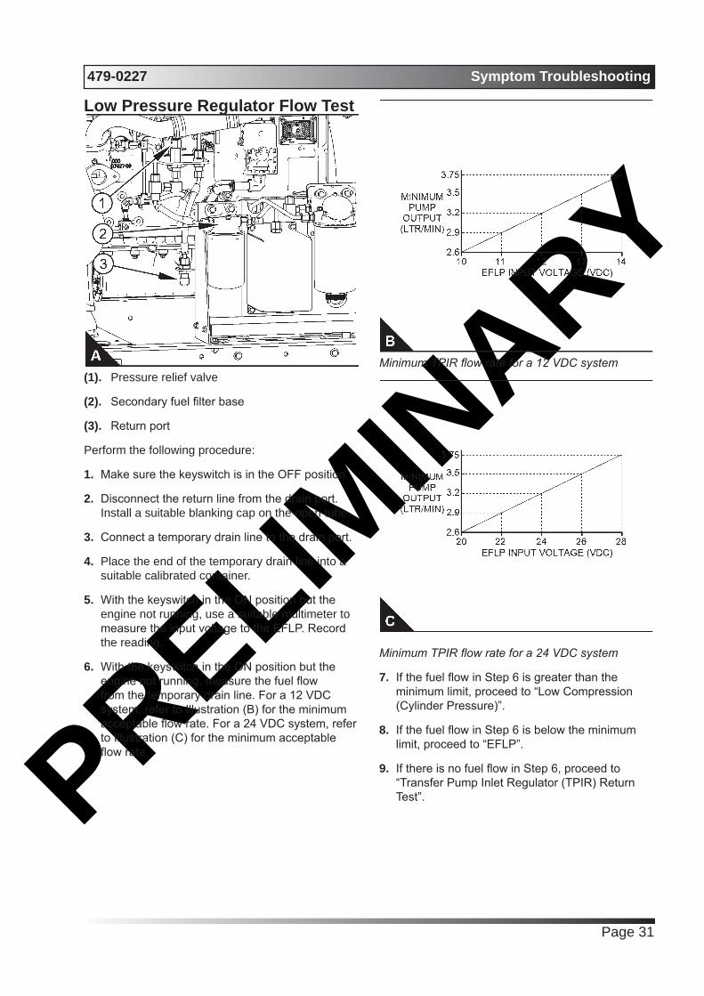
PRELIMIN
ARY479-0227 Symptom Troubleshooting
Page 31
Low Pressure Regulator Flow Test
(1). Pressure relief valve
(2). Secondary fuel filter base
(3). Return port
Perform the following procedure:
1. Make sure the keyswitch is in the OFF position
2. Disconnect the return line from the drain port. Install a suitable blanking cap on the open tube.
3. Connect a temporary drain line to the drain port.
4. Place the end of the temporary drain line into a suitable calibrated container.
5. With the keyswitch in the ON position but the engine not running, use a suitable multimeter to measure the input voltage to the EFLP. Record the reading.
6. With the keyswitch in the ON position but the engine not running, measure the fuel flow from the temporary drain line. For a 12 VDC system, refer to Illustration (B) for the minimum acceptable flow rate. For a 24 VDC system, refer to Illustration (C) for the minimum acceptable flow rate.
Minimum TPIR flow rate for a 12 VDC system
Minimum TPIR flow rate for a 24 VDC system
7. If the fuel flow in Step 6 is greater than the minimum limit, proceed to “Low Compression (Cylinder Pressure)”.
8. If the fuel flow in Step 6 is below the minimum limit, proceed to “EFLP”.
9. If there is no fuel flow in Step 6, proceed to “Transfer Pump Inlet Regulator (TPIR) Return Test”.
PRELIMIN
ARYSymptom Troubleshooting 479-0227
Page 32
EFLP Flow Test at the Secondary Fuel Filter InletIn order to check the fuel flow from the EFLP at the primary fuel filter inlet, perform the following procedure:
1. Make sure the keyswitch is in the OFF position.
2. Disconnect the fuel inlet connection from the secondary fuel filter head.
3. Install a suitable blank on the fuel inlet port on the secondary fuel filter head.
4. Place the open end of the fuel inlet line in a suitable calibrated container.
5. With the keyswitch in the ON position, measure the input voltage at the EFLP. Record the result.
6. With the keyswitch in the ON position, measure the flow from the fuel inlet line. Record the result.
7. Check the recorded voltage and fuel flow on the graph in Illustration (B).
8. If the fuel flow is below the minimum value for the recorded voltage, replace the EFLP. Refer to Disassembly and Assembly, “Fuel Priming Pump - Remove and Install”.
9. If the fuel flow is above the minimum value for the recorded voltage, proceed to “Check the Return Fuel Lines”.
Check the Return Fuel Lines1. Make sure that the TPIR return line is not
blocked or kinked.
2. Make sure that fuel lines between the EFLP and the TPIR are not blocked or kinked.
3. If the fuel lines to the TPIR are clear and the EFLP is operating, replace the TPIR.
4. If the fault is still present, proceed to “Low Compression (Cylinder Pressure)”.
Low Compression (Cylinder Pressure)1. Perform a compression test. Refer to Systems
Operation, Testing, and Adjusting, “Compression - Test”.
2. If low compression is noted on any cylinders, investigate the cause and rectify any faults.
Possible causes of low compression are shown inthe following list:
• Loose glow plugs
• Faulty piston
• Faulty piston rings
• Worn cylinder bores
• Worn valves
• Faulty cylinder head gasket
• Damaged cylinder head
3. Perform all necessary repairs.
4. Ensure that the repairs have eliminated the faults.
5. If no faults are detected, proceed to “Electronic Unit Injectors”.
Electronic Injectors1. Use the electronic service tool to perform
the automatic “Cylinder Cut Out Test” . If the compression test that was performed in “Low Compression (Cylinder Pressure)” was satisfactory, the “Cylinder Cut Out Test” will identify any faulty injectors.
2. Remove any faulty electronic injectors. Refer to Disassembly and Assembly, “Electronic Injector - Remove”.
3. Install new electronic injectors. Refer to Disassembly and Assembly, “Electronic Injector - Install”.
4. Repeat the test in 1. If the fault is still apparent, remove the replacement electronic injector and install the original electronic injector. Refer to Disassembly and Assembly, “Electronic Injector - Remove” and Disassembly and Assembly, “Electronic Injector - Install”.
5. If the repair does not eliminate the fault, refer to “Individual Malfunctioning Cylinders”.
Individual Malfunctioning Cylinders1. With the engine speed at a fast idle, use the
electronic service tool to perform the manual “Cylinder Cut Out Test” . As each cylinder is cut out, listen for a change in the sound from the engine. When a cylinder is cut out, there should be a noticeable change in the sound of the engine. If a change in the sound of the engine is not noted, the isolated cylinder is not operating under normal conditions. If the isolation of a cylinder results in a change in the sound that is

PRELIMIN
ARY479-0227 Symptom Troubleshooting
Page 33
less noticeable, the cylinder may be operating below normal performance. Investigate the cause of the fault on any cylinder that is not operating. Investigate the cause of the fault on any cylinder that is operating below normal performance.
2. If the fault is still present, contact Perkins Global Technical Support.
Alternator Is NoisyRefer to Systems Operation, Testing, and Adjusting for information on possible electrical causes of this
condition.
Probable Causes• Alternator drive belt
• Alternator mounting bracket
• Alternator drive pulley
• Alternator bearings
Recommended Actions
Alternator Drive BeltInspect the condition of the alternator drive belt. If the alternator drive belt is worn or damaged, check that the drive belt for the alternator and the pulley are correctly aligned. If the alignment is correct, replace the drive belt. Refer to Disassembly and Assembly, “Alternator Belt - Remove and Install”.
Alternator Mounting BracketInspect the alternator mounting bracket for cracks and wear. Repair the mounting bracket or replace the mounting bracket. Ensure that the alternator drive belt and the alternator drive pulley are in alignment.
Alternator Drive PulleyRemove the nut for the alternator drive pulley and then inspect the nut and the drive shaft. If no damage is found, install the nut and tighten the nut to the correct torque. Refer to Disassembly and Assembly, “Alternator - Install” for the correct torque.
Alternator BearingsCheck for excessive play of the shaft in the alternator. Check for wear in the alternator bearings. The alternator is a nonserviceable item. The alternator must be replaced if the bearings are worn. Refer to Disassembly and Assembly, “Alternator - Remove” and Disassembly and Assembly, “Alternator - Install”.
Alternator ProblemProbable Causes
• Alternator drive belt
• Charging circuit
• Alternator
Recommended Actions
Alternator Drive BeltInspect the condition of the alternator drive belt. If the alternator drive belt is worn or damaged, check that the drive belt for the alternator and the pulley are correctly aligned. If the alignment is correct, replace the drive belt. Refer to Disassembly and Assembly, “Alternator Belt - Remove and Install”.
Charging CircuitInspect the battery cables, wiring, and connections in the charging circuit. Clean all connections and tighten all connections. Replace any faulty parts.
AlternatorVerify that the alternator is operating correctly. Refer to Systems Operation, Testing, and Adjusting, “Alternator - Test”. The alternator is not a serviceable item. The alternator must be replaced if the alternator is not operating correctly. Refer to Disassembly and Assembly, “Alternator - Remove” and Disassembly and Assembly, “Alternator - Install”.
Coolant Contains OilProbable Causes
• Engine oil cooler
• Cylinder head gasket
• Cylinder head
• Cylinder block
Recommended Actions
Engine Oil Cooler1. Drain the coolant from the cooling system. Drain
the lubricating oil from the engine oil cooler. Refer to the Operation and Maintenance Manual for more information.
2. Check for leaks in the oil cooler assembly. Refer to Systems Operation, Testing, and Adjusting, “Cooling System” for the correct procedure. If a leak is found, install a new oil cooler. Refer to
PRELIMIN
ARYSymptom Troubleshooting 479-0227
Page 34
Disassembly and Assembly, “Engine Oil Cooler - Remove” and Disassembly and Assembly, “Engine Oil Cooler - Install” for the correct procedure.
Cylinder Head Gasket1. Remove the cylinder head. Refer to Disassembly
and Assembly, “Cylinder Head - Remove” for the correct procedure.
2. Inspect the cylinder head gasket for faults and any signs of leakage.
3. Proceed to the recommended actions for the “Cylinder Head”.
Cylinder Head1. Check the cylinder head for flatness. Refer to
Systems Operation, Testing, and Adjusting, “Cylinder Head - Inspect” for the correct procedure.
2. Check the mating face of the cylinder head for faults and signs of leakage. If a fault is found, replace the cylinder head. If signs of leakage are found, determine the cause of the leakage. Refer to Systems Operation, Testing, and Adjusting, “Cylinder Head - Inspect” for the correct procedure.
3. Proceed to “Cylinder Block”.
Cylinder BlockInspect the top face of the cylinder block for faults and signs of leakage. If a fault is found, replace the cylinder block. If signs of leakage are found, determine the cause of the leakage. Refer to Systems Operation, Testing, and Adjusting, “Cylinder Block - Inspect” for the correct procedure.
Assembly after Repair1. Install the cylinder head. Refer to Disassembly
and Assembly, “Cylinder Head - Install”.
2. Replenish the engine with clean engine oil to the correct level. Refer to the Operation and Maintenance Manual, “Engine Oil and Filter - Change” for more information.
3. Fill the cooling system. Refer to the Operation and Maintenance Manual, “Cooling System Coolant (ELC) - Change”.
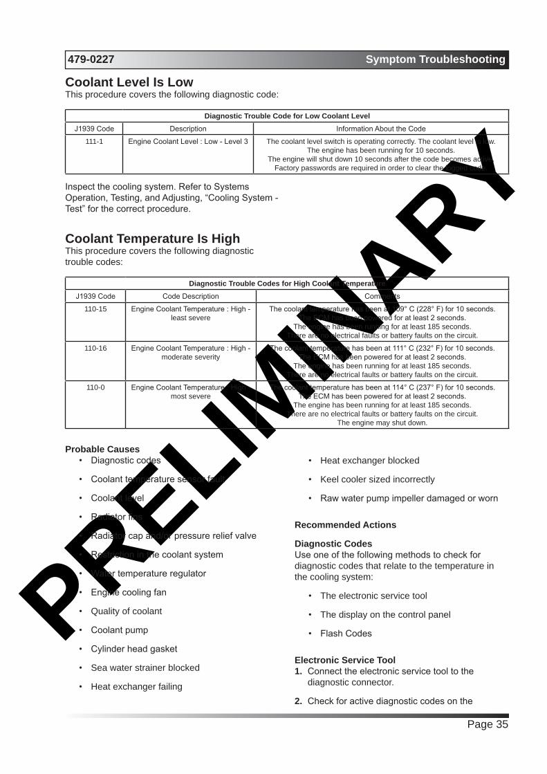
PRELIMIN
ARY479-0227 Symptom Troubleshooting
Page 35
Coolant Level Is LowThis procedure covers the following diagnostic code:
Diagnostic Trouble Code for Low Coolant LevelJ1939 Code Description Information About the Code
111-1 Engine Coolant Level : Low - Level 3 The coolant level switch is operating correctly. The coolant level is low.The engine has been running for 10 seconds.
The engine will shut down 10 seconds after the code becomes active.Factory passwords are required in order to clear the logged code.
Inspect the cooling system. Refer to Systems Operation, Testing, and Adjusting, “Cooling System - Test” for the correct procedure.
Coolant Temperature Is HighThis procedure covers the following diagnostic trouble codes:
Diagnostic Trouble Codes for High Coolant TemperatureJ1939 Code Code Description Comments
110-15 Engine Coolant Temperature : High - least severe
The coolant temperature has been at 109° C (228° F) for 10 seconds.The ECM has been powered for at least 2 seconds.
The engine has been running for at least 185 seconds.There are no electrical faults or battery faults on the circuit.
110-16 Engine Coolant Temperature : High - moderate severity
The coolant temperature has been at 111° C (232° F) for 10 seconds.The ECM has been powered for at least 2 seconds.
The engine has been running for at least 185 seconds.There are no electrical faults or battery faults on the circuit.
110-0 Engine Coolant Temperature : High - most severe
The coolant temperature has been at 114° C (237° F) for 10 seconds.The ECM has been powered for at least 2 seconds.
The engine has been running for at least 185 seconds.There are no electrical faults or battery faults on the circuit.
The engine may shut down.
Probable Causes• Diagnostic codes
• Coolant temperature sensor fault
• Coolant level
• Radiator fins
• Radiator cap and/or pressure relief valve
• Restriction in the coolant system
• Water temperature regulator
• Engine cooling fan
• Quality of coolant
• Coolant pump
• Cylinder head gasket
• Sea water strainer blocked
• Heat exchanger failing
• Heat exchanger blocked
• Keel cooler sized incorrectly
• Raw water pump impeller damaged or worn
Recommended Actions
Diagnostic CodesUse one of the following methods to check for diagnostic codes that relate to the temperature in the cooling system:
• The electronic service tool
• The display on the control panel
• Flash Codes
Electronic Service Tool1. Connect the electronic service tool to the
diagnostic connector.
2. Check for active diagnostic codes on the

PRELIMIN
ARYSymptom Troubleshooting 479-0227
Page 36
electronic service tool.
3. Investigate any active codes before continuing with this procedure. Refer to Troubleshooting, “Troubleshooting with a Diagnostic Code”.
Display on the Control PanelNote: The following procedure is only applicable if the application is equipped with a display on the control panel.
1. Check the display on the control panel for active diagnostic codes.
2. Troubleshoot any active codes before continuing with this procedure. Refer to Troubleshooting, “Troubleshooting with a Diagnostic Code”.
Flash CodesNote: The following procedure is only applicable if the machine is equipped with the appropriate warning lamps.
1. Check the warning lamps on the control panel for flash codes. Flash codes are explained in Troubleshooting, “Flash Codes”.
2. If any flash codes are displayed, troubleshoot the codes before continuing with this procedure. Refer to Troubleshooting, “Troubleshooting with a Diagnostic Code”.
Coolant Temperature GaugeCompare the readings for the coolant temperature on the electronic service tool to the reading for the coolant temperature on a calibrated test gauge.
Coolant Level1. Inspect the coolant level. If necessary, add
coolant.
2. Check the cooling system for leaks. Repair any leaks.
Raw Water Cooling1. Check the cooling system for dirt, debris, and/or
damage, remove or replace.
2. Check for collapsed hoses and/or other restrictions, repair or remove.
3. Check that the auxiliary water pump is operating correctly.
4. Check the raw water inlet for blockage or restriction.
5. Check the heat exchanger for internal blockage.
Keel Cooling1. Use the electronic service tool to check for
diagnostic codes that relate to the temperature in the cooling system.
2. Check the coolant level.
3. Check the cooling system for leaks. Refer to Troubleshoot-ing, “Coolant Level is Low” for additional information. Re-pair any leaks immediately.
4. Compare the reading for the coolant temperature on the electronic service tool to the reading for the coolant temperature on a calibrated test gauge.
5. If the temperature sensor is not accurate. Refer to Troubleshooting, “Sensor Signal (Analog, Passive) - Test”.
Radiator FinsCheck the radiator fins for dirt, debris, and/or damage. Remove any dirt and/or debris and straighten any bent fins.
Radiator Cap and/or Pressure Relief Valve1. Pressure-test the cooling system. Refer to
Systems Operation, Testing, and Adjusting, “Cooling System” for the correct procedure.
2. Check that the seating surfaces of the pressure relief valve and the radiator cap are clean and undamaged.
3. Check operation of the pressure relief valve and/or the radiator cap. If necessary, clean the components and/or replace the components.
Restriction in the Coolant System1. Visually inspect the cooling system for collapsed
hoses and/or other restrictions.
2. Clean the radiator and flush the radiator. Refer to Systems Operation, Testing, and Adjusting, “Cooling System”.
Water Temperature RegulatorCheck the water temperature regulator for correct operation. Refer to Systems Operation, Testing, and Adjusting, “Cooling System” for the proper procedure. If necessary, replace the water
PRELIMIN
ARY479-0227 Symptom Troubleshooting
Page 37
temperature regulator. Refer to Disassembly and Assembly, “Water Temperature Regulator - Remove and Install” for more information.
Engine Cooling Fan1. Make sure that the engine cooling fan is correctly
installed.
2. Make sure that the engine cooling fan is being driven correctly by the drive belt. If necessary, replace the tensioner or replace the drive belt. Refer to Disassembly and Assembly, “Alternator Belt - Remove and Install”.
3. Check the engine cooling fan for damage. If necessary, replace the fan. Refer to Disassembly and Assembly, “Fan - Remove and Install”.
Quality of CoolantCheck the quality of the coolant. Refer to the Operation and Maintenance Manual, “Refill Capacities and Recommendations - Coolant”.
Coolant Pump1. Inspect the impeller of the coolant pump for
damage and/or erosion.
2. Make sure that the drive gear is not loose on the drive shaft of the coolant pump.
3. If necessary, replace the coolant pump. Refer to Disassembly and Assembly, “Water Pump - Remove” and Disassembly and Assembly, “Water Pump - Install”.
Cylinder Head GasketSwitch off the engine and allow the engine to cool to below normal working temperature. Remove the pressure cap for the coolant system. Start the engine and inspect the coolant for the presence of bubbles. If bubbles are present in the coolant, combustion gases may be entering the cooling system. Check the cylinder head gasket. Refer to the recommended action for the cylinder head gasket within Troubleshooting, “Oil Contains Coolant”. Check the cylinder head for flatness. Refer to the recommended action for checking flatness of the cylinder head within Systems Operation, Testing, and Adjusting, “Cylinder Head - Inspect”. Fit the pressure cap if there are no bubbles in the coolant.
Cylinder Is NoisyProbable Causes
• Fuel quality
• Valve lash
• Low Compression (Cylinder Pressure)
• Injectors
• Pistons
Recommended Actions
Fuel Quality1. Check the fuel quality. Refer to Systems
Operation, Testing, and Adjusting, “Fuel Quality - Test”.
2. If unsatisfactory fuel is found, perform the following procedure.
a. Drain the fuel system.
b. Replace the fuel filters. Refer to the Operation and Maintenance Manual, “Fuel System Primary Filter (Water Separator) Element - Replace” and Operation and Maintenance Manual, “Fuel System Filter - Replace”.
c. Fill the fuel system with fuel that meets the standard in the Operation and Maintenance Manual, “Fluid Recommendations”.
d. Prime the fuel system. Refer to the Operation and Maintenance Manual, “Fuel System - Prime”.
3. If the fault is not eliminated, refer to “Valve Lash”.
Valve Lash1. Refer to Troubleshooting, “Valve Lash Is
Excessive”.
2. If the fault has not been eliminated, proceed to “Low Compression (Cylinder Pressure)”.
Low Compression (Cylinder Pressure)1. Perform a compression test. Refer to Systems
Operation, Testing, and Adjusting, “Compression - Test”.
2. If low compression is noted on any cylinders, investigate the cause and rectify any faults.
Possible causes of low compression are shown in the following list:

PRELIMIN
ARYSymptom Troubleshooting 479-0227
Page 38
• Loose glow plugs
• Faulty piston
• Faulty piston rings
• Worn cylinder bores
• Worn valves
• Faulty cylinder head gasket
• Damaged cylinder head
3. Perform all necessary repairs.
4. Ensure that the repairs have eliminated the faults.
5. If no faults are detected, proceed to “Injectors”.
Injectors1. Use the electronic service tool to perform
the automatic “Cylinder Cut Out Test” . If the compression test that was performed in “LowCompression (Cylinder Pressure)” was satisfactory, the “Cylinder Cut Out Test” will identify any faulty injectors.
2. Remove any faulty electronic unit injectors. Refer to Disassembly and Assembly, “Electronic Unit Injector - Remove”.
3. Install a new electronic unit injector. Refer to Disassembly and Assembly, “Electronic Unit Injector - Install”.
4. Repeat the test in 1. If the noise is still apparent, remove the replacement electronic unit injector and install the original electronic unit injector. Refer to Disassembly and Assembly, “Electronic Unit Injector - Remove” and Disassembly and Assembly, “Electronic Unit Injector - Install”.
5. If the fault is still apparent, refer to “Pistons”.
Pistons1. Inspect the pistons for damage and wear.
Replace any damaged parts.
2. If the noise is still present, contact Perkins Global Technical Support.
ECM Does Not Communicate with Other ModulesProbable Causes
• Electrical connectors
• Data Link
• Electronic Control Module (ECM)
• CAN data link
Recommended Actions1. Connect the electronic service tool to the
diagnostic connector. If the ECM does not communicate with the electronic service tool, refer to Troubleshooting, “Electronic Service Tool Does Not Communicate”.
2. Ensure that the following items are correctly installed and undamaged. Refer to Troubleshooting, “Electrical Connectors - Inspect”.
• J1 and J2 connectors on the ECM
• Wiring to display modules
• Wiring to other control modules
3. Troubleshoot the data link for possible faults. Refer to Troubleshooting, “Data Link Circuit - Test”.
4. Verify that the CAN data link does not have an open or short circuit. Refer to Troubleshooting, “CAN Data Link Circuit - Test”.
ECM Will Not Accept Factory PasswordsProbable CausesOne of the following items may not be recorded correctly on the electronic service tool:
• Passwords
• Serial numbers
• Total tattletale
• Reason code
Recommended Actions1. Verify that the correct passwords were entered.
Check every character in each password. Remove the electrical power from the engine for 30 seconds and then retry.
PRELIMIN
ARY479-0227 Symptom Troubleshooting
Page 39
2. Verify that the electronic service tool is displaying the “Enter Factory Passwords” dialog box.
3. Use the electronic service tool to verify that the following information has been entered correctly:
• Engine serial number
• Serial number for the electronic control module
• Serial number for the electronic service tool
• Total tattletale
• Reason code
For additional information, refer to Troubleshooting, “Factory Passwords”.
Electronic Service Tool Does Not CommunicateProbable Causes
• Configuration of the communications adapter
• Electrical connectors
• Communication adapter and/or cables
• Electrical power supply to the diagnostic connector
• Electronic service tool and related hardware
• Electrical power supply to the Electronic Control Module (ECM)
• Data Link
Recommended ActionsStart the engine. If the engine starts, but the ECM will not communicate with the electronic service tool, continue with this procedure. If the engine will not start, refer to Troubleshooting, “Engine Cranks but Does Not Start”. If the engine will not crank, refer to Troubleshooting, “Engine Does Not Crank”.
Configuration of the Communications Adapter1. Access “Preferences” under the “Utilities” menu
on the electronic service tool.
2. Verify that the correct “Communications Interface Device” is selected.
3. Verify that the correct port is selected for use by the communication adapter.
Note: The most commonly used port is “COM 1” .
4. Check for any hardware that is utilizing the same port as the communications adapter. If any devices are configured to use the same port, exit or close the software programs for that device.
Electrical ConnectorsCheck for correct installation of the P1 and P2ECM connectors and of the connector for the electronic service tool. Refer to Troubleshooting, “Electrical Connectors - Inspect”.
Communication Adapter and/or Cables1. Make sure that the firmware and driver files
are the most current files for the type of communication adapter that is being used. If the firmware and driver files do not match, the communication adapter will not communicate with the electronic service tool.
2. Disconnect the communication adapter and the cables from the diagnostic connector. Reconnect the communication adapter to the diagnostic connector.
3. Verify that the correct cable is being used between the communication adapter and the diagnostic connector. Refer to Troubleshooting, “Electronic Service Tools”.
4. If the laptop computer has a Windows operating system, restart the laptop computer in order to eliminate the possibility of a conflict in the software.
Electrical Power Supply to the Diagnostic ConnectorVerify that battery voltage is present between terminals A and B of the diagnostic connector. If the communication adapter is not receiving power, the LED display on the communication adapter will be off.
Electronic Service Tool and Related HardwareIn order to eliminate the electronic service tool and the related hardware as the fault, connect the electronic service tool to a different engine. If the same fault occurs on a different engine, check the electronic service tool and the related hardware for faults.
PRELIMIN
ARYSymptom Troubleshooting 479-0227
Page 40
Electrical Power Supply to the Electronic Control Module (ECM)Check power to the ECM. Refer to Systems Operation, Testing, and Adjusting, “Charging System - Test”.
Note: If the ECM is not receiving battery voltage, the ECM will not communicate.
Data LinkTroubleshoot the Data Link for possible faults. Refer to Troubleshooting, “Data Link Circuit - Test”.
Engine Cranks but Does Not StartProbable Causes
• Diagnostic codes
• Visible faults
• Air intake and exhaust system
• Speed/timing sensor
• Fuel system
• Glow plugs
• Ether starting aid
• Low compression (cylinder pressure)
Recommended Actions
NOTICE
Do not crank the engine continuously for more than 30 seconds. Allow the starting motor to cool for two minutes before cranking the engine again.
Diagnostic CodesUse one of the following methods to check for active diagnostic codes:
• The electronic service tool
• The display on the control panel
• Flash Codes
Electronic Service Tool1. Connect the electronic service tool to the
diagnostic connector.
2. Check for active diagnostic codes on the electronic service tool.
3. Investigate any active codes before continuing
with this procedure. Refer to Troubleshooting, “Troubleshooting with a Diagnostic Code”.
4. Attempt to start the engine. If the engine will not start, proceed to “Visible Faults”.
Display on the Control PanelNote: The following procedure is only applicable if the application is equipped with a display on the control panel.
1. Check the display on the control panel for active diagnostic codes.
2. Troubleshoot any active codes before continuing with this procedure. Refer to Troubleshooting, “Troubleshooting with a Diagnostic Code”.
3. Attempt to start the engine. If the engine will not start, proceed to “Visible Faults”.
Flash CodesNote: The following procedure is only applicable if the machine is equipped with the appropriate warning lamps.
1. Check the warning lamps on the control panel for flash codes. Flash codes are explained in Troubleshooting, “Flash Codes”.
2. If any flash codes are displayed, troubleshoot the codes before continuing with this procedure. Refer to Troubleshooting, “Troubleshooting with a Diagnostic Code”.
3. Attempt to start the engine. If the engine will not start, proceed to “Visible Faults”.
Visible Faults1. Visually inspect the engine for the following
faults:
• Missing components
• Damaged components
• Damaged electrical cables or loose electrical cables
• Oil leaks
• Fuel leaks
2. Check the following items:
• Check for the correct level of fuel, oil, and coolant.
• Ensure that the fuel supply valve (if equipped) is in the OPEN position.

PRELIMIN
ARY479-0227 Symptom Troubleshooting
Page 41
• If the ambient temperature is below 0 °C (32 °F), make sure that the correct specification of engine oil and oil for the machine is used.
• Check that the battery voltage is correct.
• Use the electronic service tool to check the average cranking speed of the engine. If the cranking speed is less than 150 rpm, investigate the cause of the low cranking speed.
• Make sure that all fuel filters are correctly installed.
• Drain any water from the primary fuel filter/ water separator.
3. Rectify any faults that are found during the visual checks.
4. Attempt to start the engine. If the engine will not start, proceed to “Air Intake and Exhaust System”.
Air Intake and Exhaust System1. Check the air filter restriction indicator, if
equipped.
2. Ensure that the air filter is clean and serviceable.
3. Check the air intake and exhaust systems for the following defects:
• Blockages
• Restrictions
• Damage to lines or hoses
4. Repair any defects before attempting to restart the engine.
5. Attempt to start the engine. If the engine will not start, proceed to “Speed/timing Sensors”.
Speed/timing Sensors1. Disconnect the connector from the primary
speed/ timing sensor.
2. Attempt to start the engine.
3. If the engine starts, check for a fault in the circuit for the primary speed/timing sensor. Refer to Troubleshooting, “Engine Speed/Timing Sensor Circuit - Test”.
4. If the engine does not start, inspect the timing ring on the crankshaft for misalignment.
5. If necessary, repair the timing ring. Refer to Disassembly and Assembly, “Crankshaft Timing Ring - Remove and Install”.
6. Connect the electronic service tool to the diagnostic connector.
7. Check that the desired fuel rail pressure is at least 25 MPa (3625 psi) when the engine is cranking.
8. If the desired fuel rail pressure is less than 25 MPa (3625 psi), perform the following procedure:
a. Use the electronic service tool to check the signal from the secondary speed/timing sensor while the engine is cranking.
b. If the signal from the secondary speed/timing sensor is 0 rpm, investigate the secondary speed/timing sensor. Refer to Troubleshooting, “Engine Speed/Timing Sensor Circuit - Test”.
c. If a fault is identified in the circuit for the secondary speed/timing sensor, repair the fault and then attempt to start the engine. If the engine will not start, proceed to “Fuel System”.
d. If the signal from the secondary speed/timing sensor is greater than 0 rpm and the engine will not start, proceed to “Fuel System”.
Fuel System1. If the temperature is below 0 °C (32 °F), check
for solidified fuel (wax).
2. Check for fuel supply lines that are restricted.
3. Check that the low-pressure fuel lines are correctly installed.
4. Check that the EFLP is operating. If the EFLP is suspect, refer to Troubleshooting, “Fuel Pump Relay Circuit - Test”.
5. Check the diesel fuel for contamination. Refer to
6. Check for air in the fuel system. Refer to Systems operation, Testing, and Adjusting, “Air in Fuel - Test”.
7. Ensure that the fuel system has been primed. Refer to Systems Operation, Testing, and Adjusting, “Fuel System - Prime”.
8. Attempt to start the engine. If the engine will not start, continue with this procedure.
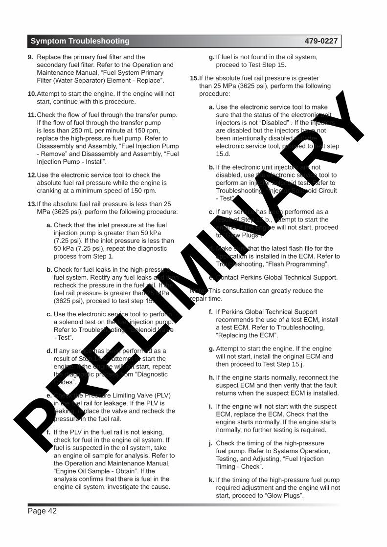
PRELIMIN
ARYSymptom Troubleshooting 479-0227
Page 42
9. Replace the primary fuel filter and the secondary fuel filter. Refer to the Operation and Maintenance Manual, “Fuel System Primary Filter (Water Separator) Element - Replace”.
10. Attempt to start the engine. If the engine will not start, continue with this procedure.
11. Check the flow of fuel through the transfer pump. If the flow of fuel through the transfer pump is less than 250 mL per minute at 150 rpm, replace the high-pressure fuel pump. Refer to Disassembly and Assembly, “Fuel Injection Pump - Remove” and Disassembly and Assembly, “Fuel Injection Pump - Install”.
12. Use the electronic service tool to check the absolute fuel rail pressure while the engine is cranking at a minimum speed of 150 rpm.
13. If the absolute fuel rail pressure is less than 25 MPa (3625 psi), perform the following procedure:
a. Check that the inlet pressure at the fuel injection pump is greater than 50 kPa (7.25 psi). If the inlet pressure is less than 50 kPa (7.25 psi), repeat the diagnostic process from Step 1.
b. Check for fuel leaks in the high-pressure fuel system. Rectify any fuel leaks and then recheck the pressure in the fuel rail. If the fuel rail pressure is greater than 25 MPa (3625 psi), proceed to test step 15.
c. Use the electronic service tool to perform a solenoid test on the fuel injection pump. Refer to Troubleshooting, “Solenoid Valve - Test”.
d. If any service has been performed as a result of Step 14.c., attempt to start the engine. If the engine will not start, repeat the diagnostic process from “Diagnostic Codes”.
e. Check the Pressure Limiting Valve (PLV) in the fuel rail for leakage. If the PLV is leaking, replace the valve and recheck the pressure in the fuel rail.
f. If the PLV in the fuel rail is not leaking, check for fuel in the engine oil system. If fuel is suspected in the oil system, take an engine oil sample for analysis. Refer to the Operation and Maintenance Manual, “Engine Oil Sample - Obtain”. If the analysis confirms that there is fuel in the engine oil system, investigate the cause.
g. If fuel is not found in the oil system, proceed to Test Step 15.
15. If the absolute fuel rail pressure is greater than 25 MPa (3625 psi), perform the following procedure:
a. Use the electronic service tool to make sure that the status of the electronic unit injectors is not “Disabled” . If the injectors are disabled but the injectors have not been intentionally disabled with the electronic service tool, proceed to test step 15.d.
b. If the electronic unit injectors are not disabled, use the electronic service tool to perform an injector solenoid test. Refer to Troubleshooting, “Injector Solenoid Circuit - Test”.
c. If any service has been performed as a result of Step 15.b., attempt to start the engine. If the engine will not start, proceed to “Glow Plugs”.
d. Make sure that the latest flash file for the application is installed in the ECM. Refer to Troubleshooting, “Flash Programming”.
e. Contact Perkins Global Technical Support.
Note: This consultation can greatly reduce the repair time.
f. If Perkins Global Technical Support recommends the use of a test ECM, install a test ECM. Refer to Troubleshooting, “Replacing the ECM”.
g. Attempt to start the engine. If the engine will not start, install the original ECM and then proceed to Test Step 15.j.
h. If the engine starts normally, reconnect the suspect ECM and then verify that the fault returns when the suspect ECM is installed.
i. If the engine will not start with the suspect ECM, replace the ECM. Check that the engine starts normally. If the engine starts normally, no further testing is required.
j. Check the timing of the high-pressure fuel pump. Refer to Systems Operation, Testing, and Adjusting, “Fuel Injection Timing - Check”.
k. If the timing of the high-pressure fuel pump required adjustment and the engine will not start, proceed to “Glow Plugs”.
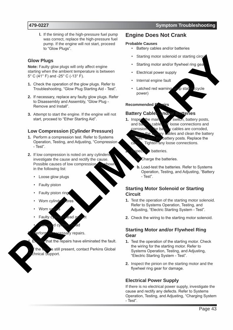
PRELIMIN
ARY479-0227 Symptom Troubleshooting
Page 43
l. If the timing of the high-pressure fuel pump was correct, replace the high-pressure fuel pump. If the engine will not start, proceed to “Glow Plugs”.
Glow PlugsNote: Faulty glow plugs will only affect engine starting when the ambient temperature is between 5° C (41° F) and -25° C (-13° F).
1. Check the operation of the glow plugs. Refer to Troubleshooting, “Glow Plug Starting Aid - Test”.
2. If necessary, replace any faulty glow plugs. Refer to Disassembly and Assembly, “Glow Plug - Remove and Install”.
3. Attempt to start the engine. If the engine will not start, proceed to “Ether Starting Aid”.
Low Compression (Cylinder Pressure)1. Perform a compression test. Refer to Systems
Operation, Testing, and Adjusting, “Compression - Test”.
2. If low compression is noted on any cylinders, investigate the cause and rectify the cause. Possible causes of low compression are shown in the following list:
• Loose glow plugs
• Faulty piston
• Faulty piston rings
• Worn cylinder bores
• Worn valves
• Faulty cylinder head gasket
• Damaged cylinder head
3. Perform all necessary repairs.
4. Ensure that the repairs have eliminated the fault.
5. If the fault is still present, contact Perkins Global Technical Support.
Engine Does Not CrankProbable Causes
• Battery cables and/or batteries
• Starting motor solenoid or starting circuit
• Starting motor and/or flywheel ring gear
• Electrical power supply
• Internal engine fault
• Latched red warning lamp status (cycle power)
Recommended Repairs
Battery Cables and/or Batteries1. Inspect the main power switch, battery posts,
and battery cables for loose connections and corrosion. If the battery cables are corroded, remove the battery cables and clean the battery cables. Clean the battery posts. Replace the cables. Tighten any loose connections.
2. Inspect the batteries.
a. Charge the batteries.
b. Load-test the batteries. Refer to Systems Operation, Testing, and Adjusting, “Battery - Test”.
Starting Motor Solenoid or Starting Circuit1. Test the operation of the starting motor solenoid.
Refer to Systems Operation, Testing, and Adjusting, “Electric Starting System - Test”.
2. Check the wiring to the starting motor solenoid.
Starting Motor and/or Flywheel Ring Gear1. Test the operation of the starting motor. Check
the wiring for the starting motor. Refer to Systems Operation, Testing, and Adjusting, “Electric Starting System - Test”.
2. Inspect the pinion on the starting motor and the flywheel ring gear for damage.
Electrical Power SupplyIf there is no electrical power supply, investigate the cause and rectify any defects. Refer to Systems Operation, Testing, and Adjusting, “Charging System - Test”.

PRELIMIN
ARYSymptom Troubleshooting 479-0227
Page 44
Internal Engine Fault1. Remove the glow plugs. Refer to Disassembly
and Assembly, “Glow Plugs - Remove and Install”.
2. Attempt to rotate the crankshaft through 360 degrees in both direction. If the crankshaft rotates correctly but fluid is expelled from the hole for the glow plug, investigate the cause of the fluid in the cylinder.
3. If the crankshaft rotates correctly and no fluid is expelled, install the glow plugs. Refer to Disassembly and Assembly, “Glow Plugs - Remove and Install”.
4. If the engine does not rotate in Step 2, disassemble the engine. Refer to Disassembly and Assembly.
5. Inspect the internal components for the following conditions:
• Seizure
• Failure
• Distortion
6. If the engine will still not crank, contact Perkins Global Technical Support.
Engine Has Early WearProbable Causes
• Multiple starts or cold operation
• Incorrect maintenance intervals
• Dirt in engine oil
• Incorrect oil
• Contaminated oil
• Leaks in air intake system
• Dirt in fuel
• Low oil pressure
Recommended Actions
Multiple Starts or Cold OperationFrequent starting and stopping of the engine can cause early wear. Also, operation of the engine for short periods of time in cold conditions can cause early wear.
Incorrect Maintenance IntervalsIf the engine is not correctly maintained, early wear will occur.
Make sure that the engine is maintained at the correct maintenance intervals. Refer to the Operation and Maintenance Manual, “Maintenance Interval Schedule”.
Dirt in Engine Oil1. Drain the oil from the crankcase and refill the
crankcase with clean engine oil. Install new engine oil filters. Refer to the Operation and Maintenance Manual for more information.
Incorrect Oil1. Check that the engine is filled with oil of the correct specification. Refer to the Operation and Maintenance Manual, “Refill Capacities and Recommendations”.
2. If necessary, drain the engine oil system and refill the engine oil system. Refer to Operation and Maintenance Manual, “Engine Oil and Filter - Change”.
Contaminated OilCheck an oil sample for contamination with fuel. If contamination is found, investigate the cause.
Leaks in Air Intake SystemA leak in the air intake system may allow unfiltered air into the engine. Inspect the air intake system for streaks which may indicate a leakage of unfiltered air. Inspect all of the gaskets and the connections. Repair any leaks. Refer to Systems Operation, Testing, and Adjusting, “Air Inlet and Exhaust System” for more information.
Dirt in Fuel 1. Remove the fuel filters. Inspect the fuel filters for contamination. Install new fuel filters. Refer to the Operation and Maintenance Manual, “Fuel System Filter- Replace” and Operation and Maintenance Manual, “Fuel System Primary Filter (Water Separator) Element - Replace”. Determine the cause of the contamination.
2. Check the diesel fuel for contamination. Refer to Systems Operation, Testing, and Adjusting, “Fuel Quality - Test”.

PRELIMIN
ARY479-0227 Symptom Troubleshooting
Page 45
Low Oil PressureRefer to Troubleshooting, “Oil Pressure Is Low” for the testing procedure. Repair any identified faults.
Engine Has Mechanical Noise (Knock)Probable Causes
• Accessory equipment
• Valve train components
• Pistons
• Connecting rod and main bearings
Recommended Actions
Accessory Equipment1. Isolate the source of the noise. Remove any
suspect engine accessory. Inspect the suspect engine accessory. Repair the engine accessory and/or replace the engine accessory if any defects are found.
2. If the mechanical noise is still apparent, refer to “Valve Train Components”.
Valve Train Components1. Check the hydraulic lifters for correct operation.
Refer to Systems Operation, Testing, and Adjusting, “Engine Valve Lash - Inspect”.
2. Inspect the following components of the valve train. Refer to Disassembly and Assembly for any components that must be removed for inspection.
• Rocker arms
• Valve bridges
• Pushrods
• Hydraulic lifters
• Camshaft
• Valve stems
• Rocker shaft
3. Check the components for the following conditions: abnormal wear, excessive wear, straightness and cleanliness. If necessary, use new parts for replacement.
Note: If the camshaft is replaced, new valve lifters must also be used.
4. If the mechanical noise is still apparent, refer to “Pistons”.
Pistons1. Inspect the pistons for damage and wear.
Replace any damaged parts.
2. If the mechanical noise is still apparent, refer to “Connecting Rod and Main Bearings”.
Connecting Rod and Main BearingsInspect the connecting rod and main bearings. Also, inspect the bearing surfaces (journals) on the crankshaft. Replace any damaged parts.
If the fault is still apparent, refer to Troubleshooting, “Cylinder Is Noisy”.
Engine Misfires, Runs Rough or Is UnstableNote: If the fault is intermittent and the fault cannot be duplicated, refer to Troubleshooting, “Intermittent Low Power or Power Cutout”.
Note: If the fault only occurs under certain conditions, test the engine under those conditions. Examples of certain conditions are high rpm, full load, and engine operating temperature. Troubleshooting the symptoms under other conditions can give misleading results.
Probable Causes• Diagnostic codes
• Throttle position sensor
• Air intake and exhaust system
• Fuel supply
• Fuel injection pump
• Low compression (cylinder pressure)
• Electronic unit injectors
• Individual malfunctioning cylinder
Recommended Actions
Diagnostic CodesUse one of the following methods to check for active diagnostic codes:
• The electronic service tool
• The display on the control panel
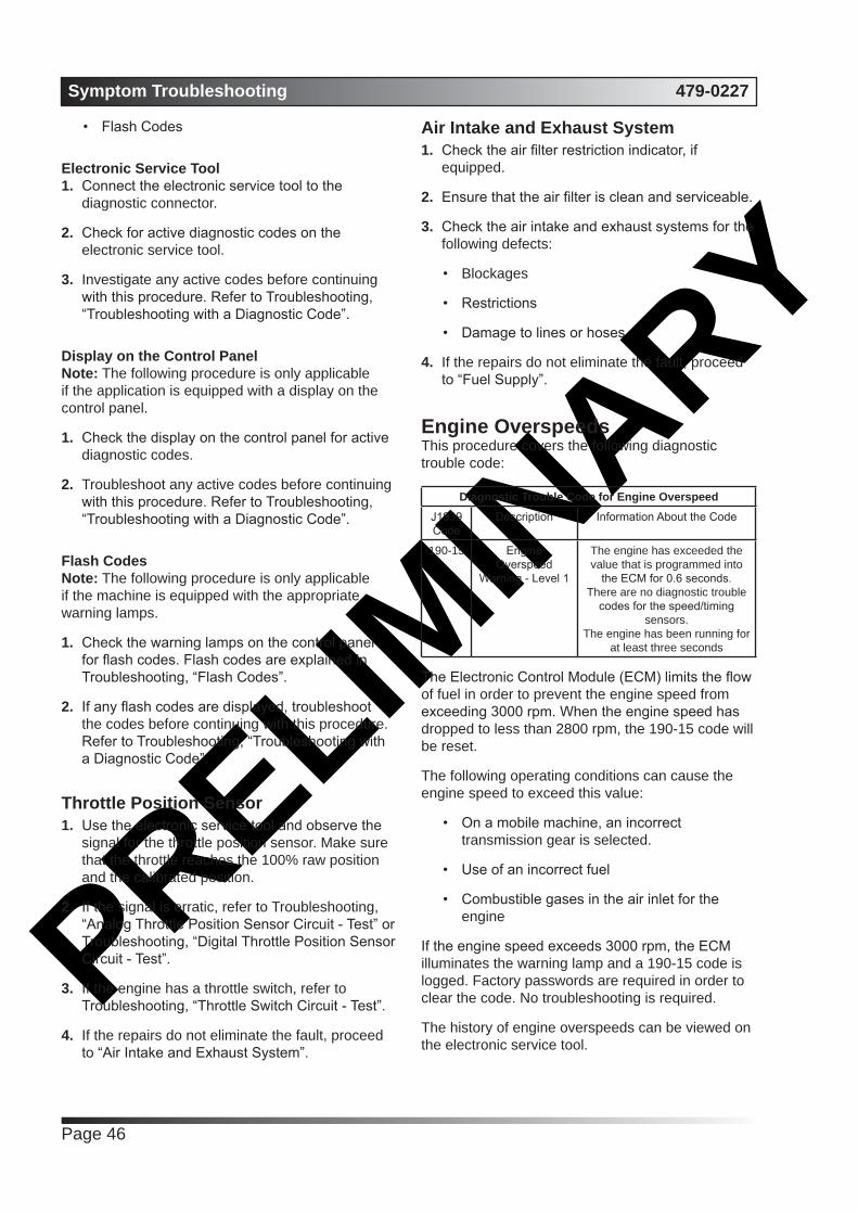
PRELIMIN
ARYSymptom Troubleshooting 479-0227
Page 46
• Flash Codes
Electronic Service Tool1. Connect the electronic service tool to the
diagnostic connector.
2. Check for active diagnostic codes on the electronic service tool.
3. Investigate any active codes before continuing with this procedure. Refer to Troubleshooting, “Troubleshooting with a Diagnostic Code”.
Display on the Control PanelNote: The following procedure is only applicable if the application is equipped with a display on the control panel.
1. Check the display on the control panel for active diagnostic codes.
2. Troubleshoot any active codes before continuing with this procedure. Refer to Troubleshooting, “Troubleshooting with a Diagnostic Code”.
Flash CodesNote: The following procedure is only applicable if the machine is equipped with the appropriate warning lamps.
1. Check the warning lamps on the control panel for flash codes. Flash codes are explained in Troubleshooting, “Flash Codes”.
2. If any flash codes are displayed, troubleshoot the codes before continuing with this procedure. Refer to Troubleshooting, “Troubleshooting with a Diagnostic Code”.
Throttle Position Sensor1. Use the electronic service tool and observe the
signal for the throttle position sensor. Make sure that the throttle reaches the 100% raw position and the calibrated position.
2. If the signal is erratic, refer to Troubleshooting, “Analog Throttle Position Sensor Circuit - Test” or Troubleshooting, “Digital Throttle Position Sensor Circuit - Test”.
3. If the engine has a throttle switch, refer to Troubleshooting, “Throttle Switch Circuit - Test”.
4. If the repairs do not eliminate the fault, proceed to “Air Intake and Exhaust System”.
Air Intake and Exhaust System1. Check the air filter restriction indicator, if
equipped.
2. Ensure that the air filter is clean and serviceable.
3. Check the air intake and exhaust systems for the following defects:
• Blockages
• Restrictions
• Damage to lines or hoses
4. If the repairs do not eliminate the fault, proceed to “Fuel Supply”.
Engine OverspeedsThis procedure covers the following diagnostic trouble code:
Diagnostic Trouble Code for Engine OverspeedJ1939 Code
Description Information About the Code
190-15 Engine Overspeed
Warning - Level 1
The engine has exceeded the value that is programmed into
the ECM for 0.6 seconds.There are no diagnostic trouble
codes for the speed/timing sensors.
The engine has been running for at least three seconds
The Electronic Control Module (ECM) limits the flow of fuel in order to prevent the engine speed from exceeding 3000 rpm. When the engine speed has dropped to less than 2800 rpm, the 190-15 code will be reset.
The following operating conditions can cause the engine speed to exceed this value:
• On a mobile machine, an incorrect transmission gear is selected.
• Use of an incorrect fuel
• Combustible gases in the air inlet for the engine
If the engine speed exceeds 3000 rpm, the ECM illuminates the warning lamp and a 190-15 code is logged. Factory passwords are required in order to clear the code. No troubleshooting is required.
The history of engine overspeeds can be viewed on the electronic service tool.

PRELIMIN
ARY479-0227 Symptom Troubleshooting
Page 47
Engine Shutdown Occurs IntermittentlyNote: Use this procedure only if the engine shuts down completely and the engine must be restarted.
Probable Causes• Diagnostic codes
• Air Intake
• Electrical connectors
• Fuel supply
Recommended Actions
Diagnostic CodesUse one of the following methods to check for active diagnostic codes:
• The electronic service tool
• The display on the control panel
• Flash Codes
Electronic Service Tool1. Connect the electronic service tool to the
diagnostic connector.
2. Check for active diagnostic codes on the electronic service tool.
3. Investigate any active codes before continuing with this procedure. Refer to Troubleshooting, “Troubleshooting with a Diagnostic Code”.
Display on the Control PanelNote: The following procedure is only applicable if the application is equipped with a display on the control panel.
1. Check the display on the control panel for active diagnostic codes.
2. Troubleshoot any active codes before continuing with this procedure. Refer to Troubleshooting, “Troubleshooting with a Diagnostic Code”.
Flash CodesNote: The following procedure is only applicable if the machine is equipped with the appropriate warning lamps.
1. Check the warning lamps on the control panel for flash codes. Flash codes are explained in Troubleshooting, “Flash Codes”.
2. If any flash codes are displayed, troubleshoot the codes before continuing with this procedure. Refer to Troubleshooting, “Troubleshooting with a Diagnostic Code”.
Air Intake1. Check the air filter for blockage or restriction.
2. Check the air intake duct for blockages or restrictions.
Electrical Connectors1. Check for correct installation of connectors at the
following locations:
• P1ECM connector
• P2ECM connector
• Connector for the solenoid on the fuel injection pump
2. Refer to Troubleshooting, “Electrical Connectors - Inspect”.
3. Inspect the battery cables from the ECM to the battery compartment. Refer to the Schematic Diagram. Inspect the cables and the power relay. Check the power and ground connections to the ECM. Refer to the schematic diagram for more information.
4. Select the “Wiggle Test” from the diagnostic tests on the electronic service tool.
5. Choose the appropriate group of parameters to monitor.
6. Press the “Start” button. Wiggle the wiring harness in order to reproduce intermittent faults.
Note: If an intermittent fault exists, the status will be highlighted and an audible beep will be heard.
7. Repair any faults and ensure that the symptom has been cleared. If the symptom is still present, refer to “Fuel Supply”.
Fuel Supply
NOTICE
Do not crank the engine continuously for more than 30 seconds. Allow the starting motor to cool for two minutes before cranking the engine again.
1. Visually check the fuel tank for fuel. The fuel gauge may be faulty.
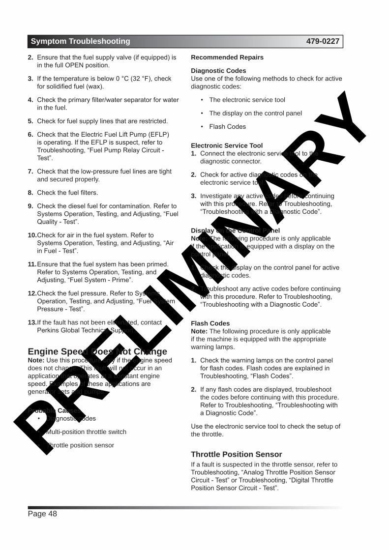
PRELIMIN
ARYSymptom Troubleshooting 479-0227
Page 48
2. Ensure that the fuel supply valve (if equipped) is in the full OPEN position.
3. If the temperature is below 0 °C (32 °F), check for solidified fuel (wax).
4. Check the primary filter/water separator for water in the fuel.
5. Check for fuel supply lines that are restricted.
6. Check that the Electric Fuel Lift Pump (EFLP) is operating. If the EFLP is suspect, refer to Troubleshooting, “Fuel Pump Relay Circuit - Test”.
7. Check that the low-pressure fuel lines are tight and secured properly.
8. Check the fuel filters.
9. Check the diesel fuel for contamination. Refer to Systems Operation, Testing, and Adjusting, “Fuel Quality - Test”.
10. Check for air in the fuel system. Refer to Systems Operation, Testing, and Adjusting, “Air in Fuel - Test”.
11. Ensure that the fuel system has been primed. Refer to Systems Operation, Testing, and Adjusting, “Fuel System - Prime”.
12. Check the fuel pressure. Refer to Systems Operation, Testing, and Adjusting, “Fuel System Pressure - Test”.
13. If the fault has not been eliminated, contact Perkins Global Technical Support.
Engine Speed Does Not ChangeNote: Use this procedure only if the engine speed does not change. This fault will not occur in an application that operates at a constant engine speed. Examples of these applications are generator sets and pumps.
Probable Causes• Diagnostic codes
• Multi-position throttle switch
• Throttle position sensor
Recommended Repairs
Diagnostic CodesUse one of the following methods to check for active diagnostic codes:
• The electronic service tool
• The display on the control panel
• Flash Codes
Electronic Service Tool1. Connect the electronic service tool to the
diagnostic connector.
2. Check for active diagnostic codes on the electronic service tool.
3. Investigate any active codes before continuing with this procedure. Refer to Troubleshooting, “Troubleshooting with a Diagnostic Code”.
Display on the Control PanelNote: The following procedure is only applicable if the application is equipped with a display on the control panel.
1. Check the display on the control panel for active diagnostic codes.
2. Troubleshoot any active codes before continuing with this procedure. Refer to Troubleshooting, “Troubleshooting with a Diagnostic Code”.
Flash CodesNote: The following procedure is only applicable if the machine is equipped with the appropriate warning lamps.
1. Check the warning lamps on the control panel for flash codes. Flash codes are explained in Troubleshooting, “Flash Codes”.
2. If any flash codes are displayed, troubleshoot the codes before continuing with this procedure. Refer to Troubleshooting, “Troubleshooting with a Diagnostic Code”.
Use the electronic service tool to check the setup of the throttle.
Throttle Position SensorIf a fault is suspected in the throttle sensor, refer to Troubleshooting, “Analog Throttle Position Sensor Circuit - Test” or Troubleshooting, “Digital Throttle Position Sensor Circuit - Test”.

PRELIMIN
ARY479-0227 Symptom Troubleshooting
Page 49
Engine Stalls at Low RPMProbable Causes
• Diagnostic codes
• Accessory equipment
• Power mode control (if equipped)
• Fuel supply
• Low compression (cylinder pressure)
• Electronic unit injectors
Recommended Actions
Diagnostic CodesUse one of the following methods to check for active diagnostic codes:
• The electronic service tool
• The display on the control panel
• Flash Codes
Electronic Service Tool1. Connect the electronic service tool to the
diagnostic connector.
2. Check for active diagnostic codes on the electronic service tool.
3. Investigate any active codes before continuing with this procedure. Refer to Troubleshooting, “Troubleshooting with a Diagnostic Code”.
Display on the Control PanelNote: The following procedure is only applicable if the application is equipped with a display on the control panel.
1. Check the display on the control panel for active diagnostic codes.
2. Troubleshoot any active codes before continuing with this procedure. Refer to Troubleshooting, “Troubleshooting with a Diagnostic Code”.
Flash CodesNote: The following procedure is only applicable if the machine is equipped with the appropriate warning lamps.
1. Check the warning lamps on the control panel for flash codes. Flash codes are explained in Troubleshooting, “Flash Codes”.
2. If any flash codes are displayed, troubleshoot
the codes before continuing with this procedure. Refer to Troubleshooting, “Troubleshooting with a Diagnostic Code”.
Accessory EquipmentCheck all accessory equipment for faults that may create excessive load on the engine. Repair any damaged components or replace any damaged components.
If there are no faults with the accessory equipment, refer to “Power Mode Control (If Equipped)”.
Power Mode Control (If Equipped)1. Check whether the power mode control is using
the data link or the CAN data link and then use the appropriate test. Refer to Troubleshooting, “Data Link Circuit - Test” or Troubleshooting, “CAN Data Link Circuit - Test”.
2. Check the engine wiring harness for defects. Refer to Troubleshooting, “Electrical Connectors - Inspect”.
3. If there are no apparent faults, refer to “Fuel Supply”.
Fuel Supply1. Visually check the fuel tank for fuel. The fuel
gauge may be faulty.
2. Ensure that the fuel supply valve (if equipped) is in the full OPEN position.
3. If the temperature is below 0 °C (32 °F), check for solidified fuel (wax).
4. Check the primary filter/water separator for water in the fuel.
5. Check for fuel supply lines that are restricted.
6. Check that the low-pressure fuel lines are tight and secured properly.
7. Replace the in-line fuel strainer that is installed upstream of the Electric Fuel Lift Pump (EFLP).
8. Check that the EFLP is operating. If the EFLP is suspect, refer to Troubleshooting, “Fuel Pump Relay Circuit - Test”.
9. Check the fuel filters.
10. Check the diesel fuel for contamination. Refer to Systems Operation, Testing, and Adjusting, “Fuel Quality - Test”.
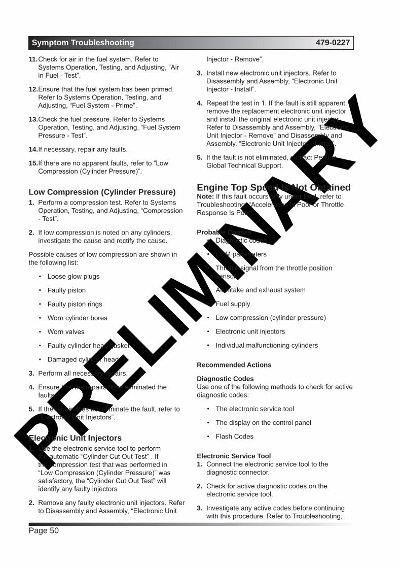
PRELIMIN
ARYSymptom Troubleshooting 479-0227
Page 50
11. Check for air in the fuel system. Refer to Systems Operation, Testing, and Adjusting, “Air in Fuel - Test”.
12. Ensure that the fuel system has been primed. Refer to Systems Operation, Testing, and Adjusting, “Fuel System - Prime”.
13. Check the fuel pressure. Refer to Systems Operation, Testing, and Adjusting, “Fuel System Pressure - Test”.
14. If necessary, repair any faults.
15. If there are no apparent faults, refer to “Low Compression (Cylinder Pressure)”.
Low Compression (Cylinder Pressure)1. Perform a compression test. Refer to Systems
Operation, Testing, and Adjusting, “Compression - Test”.
2. If low compression is noted on any cylinders, investigate the cause and rectify the cause.
Possible causes of low compression are shown in the following list:
• Loose glow plugs
• Faulty piston
• Faulty piston rings
• Worn cylinder bores
• Worn valves
• Faulty cylinder head gasket
• Damaged cylinder head
3. Perform all necessary repairs.
4. Ensure that the repairs have eliminated the faults.
5. If the repair does not eliminate the fault, refer to “Electronic Unit Injectors”.
Electronic Unit Injectors1. Use the electronic service tool to perform
the automatic “Cylinder Cut Out Test” . If the compression test that was performed in “Low Compression (Cylinder Pressure)” was satisfactory, the “Cylinder Cut Out Test” will identify any faulty injectors
2. Remove any faulty electronic unit injectors. Refer to Disassembly and Assembly, “Electronic Unit
Injector - Remove”.
3. Install new electronic unit injectors. Refer to Disassembly and Assembly, “Electronic Unit Injector - Install”.
4. Repeat the test in 1. If the fault is still apparent, remove the replacement electronic unit injector and install the original electronic unit injector. Refer to Disassembly and Assembly, “Electronic Unit Injector - Remove” and Disassembly and Assembly, “Electronic Unit Injector - Install”.
5. If the fault is not eliminated, contact Perkins Global Technical Support.
Engine Top Speed Is Not ObtainedNote: If this fault occurs only under load, refer to Troubleshooting, “Acceleration Is Poor or Throttle Response Is Poor”.
Probable Causes• Diagnostic codes
• ECM parameters
• Throttle signal from the throttle position sensor
• Air intake and exhaust system
• Fuel supply
• Low compression (cylinder pressure)
• Electronic unit injectors
• Individual malfunctioning cylinders
Recommended Actions
Diagnostic CodesUse one of the following methods to check for active diagnostic codes:
• The electronic service tool
• The display on the control panel
• Flash Codes
Electronic Service Tool1. Connect the electronic service tool to the
diagnostic connector.
2. Check for active diagnostic codes on the electronic service tool.
3. Investigate any active codes before continuing with this procedure. Refer to Troubleshooting,

PRELIMIN
ARY479-0227 Symptom Troubleshooting
Page 51
“Troubleshooting with a Diagnostic Code”.
Display on the Control PanelNote: The following procedure is only applicable if the application is equipped with a display on the control panel.
1. Check the display on the control panel for active diagnostic codes.
2. Troubleshoot any active codes before continuing with this procedure. Refer to Troubleshooting, “Troubleshooting with a Diagnostic Code”.
Flash CodesNote: The following procedure is only applicable if the machine is equipped with the appropriate warning lamps.
1. Check the warning lamps on the control panel for flash codes. Flash codes are explained in Troubleshooting, “Flash Codes”.
2. If any flash codes are displayed, troubleshoot the codes before continuing with this procedure. Refer to Troubleshooting, “Troubleshooting with a Diagnostic Code”.
ECM Parameters1. Ensure that the fault is not an incorrect or
missing programmed parameter.
2. Ensure that the correct mode was selected by using the electronic service tool.
3. Use the electronic service tool to verify the correct engine rating for the engine.
4. Use the electronic service tool to verify the maximum engine speed limit.
5. Use the electronic service tool to verify the following parameters at maximum speed: the boost pressure, the smoke limit, the torque limit and the amount of fuel that is delivered.
6. Use the electronic service tool to reset the parameters to the OEM specifications.
7. Ensure that the repairs have eliminated the fault.
8. If the repairs have not eliminated the fault, proceed to “Throttle Signal for the Throttle Position Sensor”.
Throttle Signal for the Throttle Position Sensor1. Use the electronic service tool and observe the
signal for the throttle position sensor. Make sure that the throttle reaches the 100% raw position and the calibrated position.
2. If the signal is erratic, refer to Troubleshooting, “Analog Throttle Position Sensor Circuit - Test” or refer to Troubleshooting, “Digital Throttle Position Sensor Circuit - Test”.
3. If the engine has a throttle switch, refer to Troubleshooting, “Throttle Switch Circuit - Test”.
4. If the fault has not been eliminated, proceed to “Air Intake and Exhaust System”.
Air Intake and Exhaust System1. Check the air filter restriction indicator, if
equipped.
2. Ensure that the air filter is clean and serviceable.
3. Check the air intake and the exhaust system for the following defects:
• Blockages
• Restrictions
• Damage to the air intake and exhaust lines and hoses
4. Make all necessary repairs to the engine.
5. Ensure that the repairs have eliminated the fault.
6. If the fault has not been eliminated, proceed to “Fuel Supply”.
Engine Vibration Is ExcessiveRefer to Systems Operation, Testing, and Adjusting for additional information on determining the cause of this condition.
Probable Causes• Vibration damper
• Engine supports
• Low compression (cylinder pressure)
• Electronic unit injectors
• Individual malfunctioning cylinder

PRELIMIN
ARYSymptom Troubleshooting 479-0227
Page 52
Recommended Actions
Vibration DamperCheck the vibration damper for damage. If necessary, install a new vibration damper. Inspect the mounting bolts for damage and/or for wear. Replace any damaged bolts. Refer to Disassembly and Assembly, “Vibration Damper and Pulley - Remove” and Disassembly and Assembly, “Vibration Damper and Pulley - Install”.
Ensure that the repairs have eliminated the fault. If the vibration is still present, proceed to “Engine Supports”.
Engine Supports1. Check for any of the following conditions:
• Loose engine supports
• Loose mounting brackets or broken mounting brackets
• Loose bolts
• Omitted bolts
2. Make all necessary repairs. Ensure that the repairs have eliminated the fault. If the vibration is still present, proceed to “Low Compression (Cylinder Pressure)”.
Low Compression (Cylinder Pressure)1. Perform a compression test. Refer to Systems
Operation, Testing, and Adjusting, “Compression - Test”.
2. If low compression is noted on any cylinders, investigate the cause and rectify the cause.
Possible causes of low compression are shown in the following list:
• Loose glow plugs
• Faulty piston
• Faulty piston rings
• Worn cylinder bores
• Worn valves
• Faulty cylinder head gasket
• Damaged cylinder head
3. Perform all necessary repairs.
4. Ensure that the repairs have eliminated the fault.
5. If the repair does not eliminate the fault, proceed to “Electronic Unit Injectors”.
Exhaust Has Excessive White SmokeNote: Some white smoke may be present during cold start-up conditions and during acceleration after a prolonged period at low idle. If the white smoke persists, there may be a fault.
Probable Causes• Diagnostic codes
• Coolant temperature sensor circuit
• Low coolant temperature
• Cooling system
• Glow plugs
• Fuel quality
• Valve lash
• Low compression (cylinder pressure)
• Individual malfunctioning cylinder
Recommended Actions
Diagnostic CodesUse one of the following methods to check for active diagnostic codes:
• The electronic service tool
• The display on the control panel
• Flash Codes
Electronic Service Tool1. Connect the electronic service tool to the
diagnostic connector.
2. Check for active diagnostic codes on the electronic service tool.
3. Investigate any active codes before continuing with this procedure. Refer to Troubleshooting, “Troubleshooting with a Diagnostic Code”.
Display on the Control PanelNote: The following procedure is only applicable if the application is equipped with a display on the control panel.
1. Check the display on the control panel for active

PRELIMIN
ARY479-0227 Symptom Troubleshooting
Page 53
diagnostic codes.
2. Troubleshoot any active codes before continuing with this procedure. Refer to Troubleshooting, “Troubleshooting with a Diagnostic Code”.
Flash CodesNote: The following procedure is only applicable if the machine is equipped with the appropriate warning lamps.
1. Check the warning lamps on the control panel for flash codes. Flash codes are explained in Troubleshooting, “Flash Codes”.
2. If any flash codes are displayed, troubleshoot the codes before continuing with this procedure. Refer to Troubleshooting, “Troubleshooting with a Diagnostic Code”.
Coolant Temperature Sensor Circuit1. Connect the electronic service tool to the
diagnostic connector.
2. Monitor the display screen on the electronic service tool in order to verify the presence of active diagnostic codes for the coolant temperature. Refer to Troubleshooting, “Engine Temperature Sensor Open or Short Circuit - Test”.
3. If the fault has not been eliminated, proceed to “Low Coolant Temperature”.
Low Coolant TemperatureCheck that the water temperature regulator is operating correctly. Refer to Systems Operation, Testing, and Adjusting, “Water Temperature Regulator - Test”.
If the water temperature regulator is operating correctly, proceed to “Cooling System”.
Cooling SystemCheck for an internal coolant leak into the cylinder and/or the exhaust. Refer to Systems Operation/ Testing and Adjusting, “Cooling System”.
Note: Check for leakage at the ARD nozzle heater o- rings. If the o-rings are leaking coolant, replace the ARD head.
Glow PlugsNote: Faulty glow plugs will only affect the production of white smoke when the ambient temperature is between 5° C (41° F) and -25° C (-13° F).
1. 1. Check for correct operation of the glow plugs. Refer to Troubleshooting, “Glow Plug Starting Aid - Test”.
2. 2. If necessary, replace faulty glow plugs. Refer to Disassembly and Assembly, “Glow Plug - Remove and Install”.
3. 3. If the repairs do not eliminate the fault, proceed to “Ether Injection”.
Fuel Quality1. Check the diesel fuel for quality. Refer to
Systems Operation, Testing, and Adjusting, “Fuel Quality - Test”.
Note: Diesel fuel with a low cetane value is likely to cause white smoke.
2. If the repair does not eliminate the fault, proceed to “Valve Lash”.
Valve Lash1. Ensure that the valve lash is correct. Refer to
Systems Operation, Testing, and Adjusting, “Engine Valve Lash - Inspect”.
2. If the repair does not eliminate the fault, proceed to “Low Compression (cylinder pressure)”.
Low Compression (cylinder pressure)1. Perform a compression test. Refer to Systems
Operation, Testing, and Adjusting, “Compression - Test”.
2. If low compression is noted on any cylinders, investigate the cause and rectify the cause.
Fuel Consumption Is ExcessiveProbable Causes
• Diagnostic codes
• Misreading of fuel level
• Fuel leakage
• Fuel quality
• Quality of oil

PRELIMIN
ARYSymptom Troubleshooting 479-0227
Page 54
• Low engine temperature
• Prolonged operation at idle speed
• Engine operating speed
• Air intake and exhaust system
• Aftertreatment Regeneration Device (ARD)
• Cooling fan
• Reduced pressure of intake air
• Excessive valve lash
• Failure of the primary speed/timing sensor
Recommended Actions
Diagnostic CodesUse one of the following methods to check for active diagnostic codes:
• The electronic service tool
• The display on the control panel
• Flash Codes
Electronic Service Tool1. Connect the electronic service tool to the
diagnostic connector.
2. Check for active diagnostic codes on the electronic service tool.
3. Investigate any active codes before continuing with this procedure. Refer to Troubleshooting, “Troubleshooting with a Diagnostic Code”.
Display on the Control PanelNote: The following procedure is only applicable if the application is equipped with a display on the control panel.
1. Check the display on the control panel for active diagnostic codes.
2. Troubleshoot any active codes before continuing with this procedure. Refer to Troubleshooting, “Troubleshooting with a Diagnostic Code”.
Misreading of Fuel Level1. Monitor the fuel consumption over a period
of 50 engine hours. If the fuel consumption is excessive, perform the following procedure.
Fuel Quality1. The quality of the fuel that is used in the engine
will affect the rate of fuel consumption. Refer to “General Fuel Information” in the Operation and Maintenance Manual, “Refill Capacities”.
2. If the fuel is not of an acceptable quality, drain the fuel system and replace the fuel filters. Refill the fuel system with fuel of an acceptable quality.
Refer to the applicable sections in the Operation and Maintenance Manual.
3. If the fuel is of an acceptable quality, refer to “Quality of Oil”.
Quality of Oil1. The nominal viscosity of the lubricating oil that
is used in the engine will affect the rate of fuel consumption. The viscosity of lubricating oil is defined by the SAE grade of the lubricating oil. The grade of the lubricating oil must be correct for the ambient conditions. Lubricating oil for high ambient temperatures will affect fuel consumption in cold ambient temperatures. Refer to “Engine Oil” in the Operation and Maintenance Manual, “Refill Capacities”.
2. The actual viscosity of the lubricating oil that is used in the engine will change throughout the service life of the oil. Lubricating oil that is heavily contaminated will have a negative effect upon the rate of fuel consumption.
3. If the quality of the oil is unacceptable or if the oil has exceeded the service life, drain the oil system and replace the oil filter. Refill the oil system with oil of an acceptable quality. Refer to the applicable sections in the Operation and Maintenance Manual.
4. If the oil is of an acceptable quality, refer to “Low Engine Temperature”.
Low Engine Temperature1. The operating temperature of the engine will
affect the rate of fuel consumption. Operation of the engine below the correct temperature will increase fuel consumption. Failure of the water temperature regulator can prevent the engine from operating at the correct temperature.
2. If the engine operating temperature is low, check the operation of the water temperature regulator. If the water temperature regulator does not operate correctly, a new water temperature regulator must be installed. Refer to Disassembly

PRELIMIN
ARY479-0227 Symptom Troubleshooting
Page 55
and Assembly, “Water Temperature Regulator - Remove and Install”.
Prolonged Operation at Idle SpeedProlonged operation of the engine at idle speed increases fuel consumption.
When the engine is operated at idle speed, the fuel that is consumed provides no useful work. Prolonged operation at idle speed will cause a measurable deterioration in the overall fuel consumption of the engine.
Operation of the engine for long periods at idle speed will cause a deterioration of the internal components of the engine. A deterioration of the internal components of the engine will increase fuel consumption.
Engine Operating SpeedThe operating speed of the engine will affect the rate of fuel consumption.
High engine speed will increase fuel consumption. At high engine speeds, internal power losses in the engine increase and more power is required to drive the alternator and the fan. The power losses increase fuel consumption.
Lugging down the engine to a low engine speed will increase fuel consumption. At low engine speeds, the combustion efficiency of the engine is reduced and more fuel will be used.
Air Inlet and Exhaust SystemLeakage of gas or a restriction in the air intake or the exhaust system can reduce the flow of combustion gas through the engine. A change in the flow of combustion air into the engine adversely affects combustion efficiency and the rate of fuel consumption.
1. Check the air intake system for leakage or restrictions. Refer to Systems Operation, Testing, and Adjusting, “Air Inlet and Exhaust System”.
2. Check the exhaust system for leakage or restrictions. Refer to Systems Operation, Testing, and Adjusting, “Air Inlet and Exhaust System”.
3. Repair all defects. Verify that the repair has eliminated the fault.
Cooling FanExcessive operation of the cooling fan will increase fuel consumption. Investigate the cause of
excessive operation of the cooling fan.
Reduced Pressure of Intake Air1. If the pressure of the intake air at the intake
manifold is lower than normal, either the speed of the engine will need to be higher or more fuel must be injected in order to produce the same power. Either of these conditions will increase the fuel consumption.
2. Check all pipes from the outlets of the turbocharger compressors to the inlet manifold for leaks. Check the aftercooler and the NRS mixer for air leaks If necessary, repair any leaks.
3. Check for the correct operation of the wastegate in the high-pressure turbocharger. Refer to Systems Operation, Testing, and Adjusting, “Turbocharger - Inspect”.
4. If a turbocharger is suspected as being faulty, replace the turbocharger. Refer to Disassembly and Assembly, “Turbocharger - Remove” and Disassembly and Assembly, “Turbocharger - Install”.
Excessive Valve LashExcessive valve lash will cause a change in the timing of the opening and closing of the inlet and exhaust valves. Excessive valve lash can cause a reduction of the flow of combustion air into the engine. Reduced flow of combustion air will increase the fuel consumption rate.
Refer to Troubleshooting, “Valve Lash Is Excessive”.
Failure of the Primary Speed/Timing SensorIf the primary speed/timing sensor fails, the engine will continue to operate using the signal from the secondary speed/timing sensor. The secondary speed/timing sensor is less precise than the primary speed/timing sensor. Timing differences between the secondary speed/timing sensor and the primary speed/timing sensor may cause an increase in fuel consumption.
1. Use the electronic service tool to check for active diagnostic codes that relate to the primary speed/ timing sensor.
2. If necessary, replace the primary speed/timing sensor. Refer to Disassembly and Assembly, “Crankshaft Position Sensor - Remove and Install”.

PRELIMIN
ARYSymptom Troubleshooting 479-0227
Page 56
Fuel Rail Pressure ProblemUse this procedure in order to troubleshoot abnormal fuel rail pressure or use this procedure if any of the following diagnostic trouble codes are active. Refer to Troubleshooting, “Diagnostic Trouble Codes” for information about the codes.
Diagnostic Trouble CodesJ1939 Code Code Description Comments
157-16 Engine Injector Metering Rail #1 Pressure: High moderate severity (2)
No other 157-XX codes are active.3509-XX codes are not active.3510-XX codes are not active.
No codes for the high-pressure fuel pump or the injectors are active.The fuel rail pressure is above an acceptable level.
The code is logged.Engine power is derated.
157-18 Engine Injector Metering Rail #1 Pressure: Low - moderate
severity (2)
3509-XX codes are not active.3510-XX codes are not active.
No codes for the high-pressure fuel pump or the injectorsare active.
The fuel rail pressure is below an acceptable level.The code is logged.
Engine power is derated.
1239-0 Engine Fuel Leakage 1: High - most severe (3)
3509-XX codes are not active.3510-XX codes are not active.
There is a probable fuel leak from the high-pressure fuelsystem. The amount of leakage is a calculated parameter.
The code is logged.The engine will shut down.
5571-0 High Pressure Common Rail Fuel Pressure Relief Valve: Active
3509-XX codes are not active.3510-XX codes are not active.
The pressure limiting valve in the fuel rail is open. This codeis a calculated parameter.
The code is logged.
Probable Causes• Diagnostic trouble codes
• Electrical connectors
• Fuel filters
• Fuel rail pressure sensor
• Fuel system
Recommended Actions
Diagnostic Trouble CodesUse one of the following methods to check for active diagnostic trouble codes:
• The electronic service tool
• The display on the control panel
• Flash Codes
Electronic Service Tool1. Connect the electronic service tool to the
diagnostic connector.
2. Check for active diagnostic trouble codes on the electronic service tool.
3. Investigate any active codes before continuing with this procedure. Refer to Troubleshooting, “Troubleshooting with a Diagnostic Code”.
Display on the Control PanelNote: The following procedure is only applicable if the application is equipped with a display on the control panel.
1. Check the display on the control panel for active diagnostic trouble codes.
2. Troubleshoot any active codes before continuing with this procedure. Refer to Troubleshooting, “Diagnostic Trouble Codes”.
Flash CodesNote: The following procedure is only applicable if the machine is equipped with the appropriate warning lamps.
1. Check the warning lamps on the control panel

PRELIMIN
ARY479-0227 Symptom Troubleshooting
Page 57
for flash codes. Flash codes are explained in Troubleshooting, “Flash Codes”.
2. If any flash codes are displayed, troubleshoot the codes before continuing with this procedure. Refer to Troubleshooting, “Diagnostic Trouble Codes”.
Electrical Connections1. Check for correct installation of the P1 and
P2 connectors on the ECM. Check for correct installation of all other applicable connectors. Refer to Troubleshooting, “Electrical Connectors - Inspect”.
2. Use the electronic service tool to perform a wiggle test.
3. If necessary, perform any repairs to the connectors or the wiring.
4. Check if the fault has been eliminated. If the fault is still present, proceed to “Fuel Filters”.
Fuel Filters1. Replace the primary fuel filter and the secondary
fuel filter. Refer to the applicable procedure in the Operation and Maintenance Manual.
2. Check if the fault has been eliminated. If the fault is still present, proceed to “Fuel Rail Pressure Sensor”.
Fuel Rail Pressure Sensor1. With the engine shutdown, use the electronic
service tool to check the status of the “Fuel Rail Pressure” . After the engine has been shut down for 10 minutes, the “Fuel Rail Pressure (absolute)” must be less than 5,000 kPa (725 psi) (gauge).
2. If the “Fuel Rail Pressure” on the electronic service tool is less than 5,000 kPa (725 psi), proceed to Step “Fuel System”.
3. If the “Fuel Rail Pressure” on the electronic service tool does not fall to less than 5,000 kPa (725 psi) (gauge), the fuel rail pressure sensor may be faulty. Refer to Troubleshooting, “Engine Pressure Sensor Open or Short Circuit - Test”.
4. Use the electronic service tool in order to perform the “Fuel Rail Pressure Test”. If the test fails, replace the fuel rail. Refer to Disassembly and Assembly, “Fuel Manifold (Rail) - Remove and Install”.
5. If the fault is still present, refer to “Fuel System”.

PRELIMIN
ARYSymptom Troubleshooting 479-0227
Page 58
Fuel Temperature Is HighIf either of the following diagnostic trouble codes are active, perform the procedure that follows:
Diagnostic Trouble Code Description Details174-15 Engine Fuel Temperature 1 :
High - least severe (1)The temperature of the low-pressure fuel in the high-pressure fuel
pump is high.The ECM has been powered for at least 2 seconds.
The engine has been operating for at least 185 seconds.There are no other faults in the electrical system.
The warning lamp will come on.The warning lamp will go off when the temperature drops below the
trip point.
174-16 Engine Fuel Temperature 1 : High - moderate severity (2)
The temperature of the low-pressure fuel in the high-pressure fuel pump is high.
The ECM has been powered for at least 2 seconds.The engine has been operating for at least 185 seconds.
There are no other faults in the electrical system.The warning lamp will come on.
The engine may be derated by 20%.The warning lamp will go off when the temperature drops below the
trip point for 15 seconds.
Probable Causes• Incorrect position of fuel shut-off valves
• Fuel level in tank
• Return fuel cooler
• Return fuel lines
• Location of the fuel tank
Recommended Actions
Incorrect Position of Fuel Shut-off ValvesMake sure that any fuel shut-off valves in the feed lines between the fuel tank and the engine are open.
Make sure that any fuel shut-off valves in the return lines between the engine and the fuel tank are open.
Fuel Level in TankIf the level in the fuel tank is low, the hot return fuel can raise the temperature in the fuel tank. Replenish the fuel tank at the earliest opportunity.
Return Fuel LinesNote: The return fuel lines are installed by the machine manufacturer. The design and location of the lines can vary.
Make sure that the return fuel lines are not blocked or restricted. If necessary, clear or replace any return fuel lines.
Location of the Fuel TankMake sure that the fuel tank is not close to a heat
source. If necessary, shield the fuel tank from the heat source or relocate the fuel tank to a cooler location.
Inlet Air Is RestrictedThe Electronic Control Module (ECM) detects a fault with the air flow through the air filter. If the air flow has been restricted, the ECM will generate the following code:
Code for Inlet Air RestrictionJ1939 Code Description Information
? Air pressure low
The engine has been operating for 3 minutes.
The warning lamp will come on.
The code will be reset when the keyswitch is turned to the
OFF position.Probable Causes
• High ambient air temperature
• Intake air restriction and/or high altitude
• Intake air from a heated area
Recommended Actions
Diagnostic CodesUse one of the following methods to check for active diagnostic codes:
• The electronic service tool
• The display on the control panel
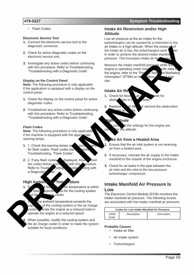
PRELIMIN
ARY479-0227 Symptom Troubleshooting
Page 59
• Flash Codes
Electronic Service Tool1. Connect the electronic service tool to the
diagnostic connector.
2. Check for active diagnostic codes on the electronic service tool.
3. Investigate any active codes before continuing with this procedure. Refer to Troubleshooting, “Troubleshooting with a Diagnostic Code”.
Display on the Control PanelNote: The following procedure is only applicable if the application is equipped with a display on the control panel.
1. Check the display on the control panel for active diagnostic codes.
2. Troubleshoot any active codes before continuing with this procedure. Refer to Troubleshooting, “Troubleshooting with a Diagnostic Code”.
Flash CodesNote: The following procedure is only applicable if the machine is equipped with the appropriate warning lamps.
1. 1. Check the warning lamps on the control panel for flash codes. Flash codes are explained in Troubleshooting, “Flash Codes”.
2. 2. If any flash codes are displayed, troubleshoot the codes before continuing with this procedure. Refer to Troubleshooting, “Troubleshooting with a Diagnostic Code”.
High Ambient Air Temperature1. Determine if the ambient air temperature is within
the design specifications for the cooling system and the air charge cooler.
2. When the ambient temperature exceeds the capability of the cooling system or the air charge cooler, operate the engine at a reduced load or operate the engine at a reduced speed.
3. When possible, modify the cooling system and the air charge cooler in order to make the system suitable for local conditions.
Intake Air Restriction and/or High AltitudeLow air pressure at the air intake for the turbochargers can be caused by a restriction in the air intake or a high altitude. When the pressure of the intake air is low, the turbochargers work harder in order to achieve the desired intake manifold pressure. This increases intake air temperature.
Measure the intake manifold pressure while the engine is operating under load. For specific data for the engine, refer to the “Perkins Technical Marketing Information” (PTMI) on the Perkins secured web site.
Intake Air Restriction1. Check for blocked air filters. Check for
obstructions in the air intake.
2. Replace the air filters or remove the obstruction from the air intake.
High AltitudeMake sure that the settings for the engine are correct for the altitude.
Intake Air from a Heated Area1. Ensure that the air inlet system is not receiving
air from a heated area.
2. If necessary, relocate the air supply to the intake manifold to the outside of the engine enclosure.
3. Check for air leaks in the pipe between the air inlet and the inlet to the low-pressure turbocharger compressor.
Intake Manifold Air Pressure Is LowThe Electronic Control Module (ECM) monitors the intake manifold air pressure. The following events are associated with low intake manifold air pressure:
Codes for Low Intake Manifold Air PressureJ1939 Code
Description Information
Probable Causes• Intake air filter
• Air intake system
• Turbochargers

PRELIMIN
ARYSymptom Troubleshooting 479-0227
Page 60
Recommended Actions
Intake Air Filter1. Check the air filter restriction indicator, if
equipped.
2. Ensure that the air filter is clean and serviceable.
3. If necessary, replace the air filter element. Refer to the Operation and Maintenance Manual, “Engine Air Cleaner Element - Replace”.
4. Check that the fault has been eliminated.
5. If the fault has not been eliminated, proceed to “Air Intake System”.
Air Intake System1. Check the air intake system for the following
defects:
• Blockages
• Restrictions
• Damage to the air intake ducts and hoses
• Loose connections and air leaks
2. Make all necessary repairs to the engine.
3. Ensure that the repairs have eliminated the fault.
TurbochargerNote: The turbocharger that are installed on the engine are nonserviceable items. If any mechanical fault exists, then the faulty turbocharger must be replaced.
1. Check that the compressor housings for the turbocharger are free of dirt and debris.
2. Check that the turbine housings for the turbocharger are free of dirt and debris.
3. Check that the turbine blades rotate freely in the turbocharger.
4. If necessary, replace the faulty turbocharger. Refer to Disassembly and Assembly, “Turbocharger - Remove” and Disassembly and Assembly, “Turbocharger - Install”.
5. Check that any repairs have eliminated the fault.
6. If the fault is still present, contact Perkins Global Technical Support.
Intake Manifold Air Temperature Is HighThe Electronic Control Module (ECM) monitors the intake manifold air for excessive temperature. The following events are associated with high intake manifold air temperature:
Diagnostic Codes for High Intake Manifold Air Temperature
J1939 Code
Description Information
105-15 Engine Intake Manifold #1 Temperature : High - least severe (1)
The engine has been running for 3 minutes.
No other 105 codes are active.168 codes are not active.Code 412-16 is not active.
The intake manifold air temperature exceeds the value
that is programmed into the ECM for 8 seconds. The code is
logged.This code will be reset when the temperature is less than 122° C
(252° F) for 4 seconds.
105-16 Engine Intake Manifold #1 Temperature
: High - Moderate
Severity (2)
The engine has been running for 3 minutes.
No other 105 codes are active.168 codes are not active.Code 412-16 is not active.
The intake manifold air temperature exceeds the value
that isprogrammed into the ECM for 8 seconds. The engine will be
de rated. The code is logged.This code will be reset when the temperature is less than 124° C
(255° F) for 20 seconds.
Use this procedure to determine the cause of high intake manifold air temperature.
1. Verify that the coolant is filled to the proper level. If the coolant level is too low, air will get into the cooling system. Air in the cooling system will cause a reduction in coolant flow. Coolant flow is required in order to cool the intake air.
2. Check the aftercooler for debris or damage. Debris between the fins of the aftercooler core restricts air flow through the core.
3. Check the operation of the cooling fan. A fan that is not turning at the correct speed can cause improper air speed across the aftercooler core. The lack of proper air flow across the aftercooler core can cause the intake air not to cool to the proper temperature.
4. Check for a restriction in the air inlet system. A restriction of the air that is coming into the engine can cause high cylinder temperatures. High cylinder temperatures cause higher than normal temperatures in the cooling system. The coolant
PRELIMIN
ARY479-0227 Symptom Troubleshooting
Page 61
temperature must be within the correct range in order to cool the intake air.
5. Check for a restriction in the exhaust system. A restriction of the air that is coming out of the engine can cause high cylinder temperatures.
6. Check for a high ambient temperature. When outside temperatures are too high for the rating of the cooling system, there is not enough of a temperature difference between the outside air and coolant temperatures.
7. Make an allowance for high altitude operation. The cooling capacity of the cooling system is reduced as the engine is operated at higher altitudes.
8. The engine may be running in the lug condition. When the load that is applied to the engine is too large, the engine will run in the lug condition. When the engine is running in the lug condition, engine rpm does not increase with an increase of fuel. This lower engine rpm causes a reduction in coolant flow through the system.
9. If the cause of the high intake manifold air temperature cannot be determined, contact Perkins Global Technical Support.
Oil Consumption Is ExcessiveProbable Causes
• Misreading oil level
• Oil leaks
• Engine crankcase breather
• Oil level
• Air intake and exhaust system
• Turbochargers
• Low compression (cylinder pressure)
Recommended Actions
Misreading Oil Level1. Accurately measure the consumption of oil and
fuel over a period of 50 engine hours.
2. If the oil consumption is greater than 0.08% of the fuel consumption, use the following procedure to investigate the cause.
Oil Leaks1. Check for evidence of oil leaks on the engine.
2. Rectify any oil leaks from the engine.
3. Check for evidence of oil in the coolant. If oil is found in the coolant, refer to Troubleshooting, “Coolant Contains Oil”.
4. If no oil leaks are identified, refer to “Engine Crankcase Breather”.
Engine Crankcase Breather1. Check the engine crankcase breather for
blockage or restrictions.
2. Check for excessive oil from the outlet of the breather.
3. If necessary, replace the filter in the breather.
4. Repair all defects. Verify that the repair has eliminated the fault.
5. If no faults are found, refer to “Oil Level”.
Oil Level1. Check the oil level in the engine.
2. If no contamination is identified, remove any excess oil.
3. If the oil level is satisfactory, refer to “Air Intake and Exhaust System”.
Air Intake and Exhaust System1. Check the air filter restriction indicator, if
equipped.
2. Ensure that the air filter is clean and serviceable.
3. Check the air intake and the exhaust system for the following defects:
• Blockages
• Restrictions
• Damage to the air intake and exhaust lines and hoses
4. Make all necessary repairs to the engine.
5. Ensure that the repairs have eliminated the fault.
6. If no faults are found, refer to “Turbochargers”.

PRELIMIN
ARYSymptom Troubleshooting 479-0227
Page 62
TurbochargerNote: The turbocharger that is installed on this engine is a nonserviceable items. If any mechanical fault exists, then the faulty turbocharger must be replaced.
1. Check that the oil drain for the turbocharger is not blocked or restricted.
2. Check the turbocharger for evidence of internal oil leaks. If evidence is found of an oil leak into the exhaust system, inspect the diesel particulate filter for blockage of the filter inlet.
3. If necessary, replace the faulty turbocharger. Refer to Disassembly and Assembly, “Turbocharger - Remove” and Disassembly and Assembly, “Turbocharger - Install”.
4. If oil is found in the inlet face of the DPF, make sure that the cause has been rectified. Clean the oil from the inside of the inlet section of the DPF and the front face of the DPF. Assemble the DPF. Run the engine at 1400 rpm for 15 minutes.
5. Check that the repairs have eliminated the faults.
6. If the repairs have not eliminated the fault, proceed to “Low Compression (cylinder pressure)”.
Low Compression (cylinder pressure)1. Perform a compression test. Refer to Systems
Operation, Testing, and Adjusting, “Compression - Test”.
2. If low compression is noted on any cylinders, investigate the cause and rectify the cause.
Possible causes of low compression are shown in the following list:
• Loose glow plugs
• Faulty piston
• Worn piston rings
• Worn cylinder bores
• Worn valves
• Faulty cylinder head gasket
• Damaged cylinder head
3. Perform all necessary repairs.
4. Ensure that the repairs have eliminated the faults.
5. If the fault is not eliminated, contact PerkinsGlobal Technical Support.
Oil Contains CoolantProbable Causes
• Engine oil cooler
• Cylinder head gasket
• Cylinder head
• Cylinder block
Recommended Actions
Engine Oil Cooler1. Drain the engine lubricating oil from the engine.
2. Check for leaks in the oil cooler assembly. Refer to Systems Operation, Testing, and Adjusting, “Cooling System” for the correct procedure. If a leak is found, install a new oil cooler. Refer to Disassembly and Assembly, “Engine Oil Cooler - Remove” and Disassembly and Assembly, “Engine Oil Cooler - Install” for the correct procedure.
Cylinder Head Gasket1. Remove the cylinder head. Refer to Disassembly
and Assembly, “Cylinder Head - Remove” for the correct procedure.
2. Inspect the cylinder head gasket for faults and any signs of leakage.
3. Proceed to the recommended actions for “Cylinder Head”.
Cylinder Head1. Check the cylinder head for flatness. Refer to
Systems Operation, Testing, and Adjusting, “Cylinder Head - Inspect” for the correct procedure.
2. Check the mating face of the cylinder head for faults and signs of leakage. If a fault is found, replace the cylinder head. If signs of leakage are found, determine the cause of the leakage. Refer to Systems Operation, Testing, and Adjusting, “Cylinder Head - Inspect” for the correct procedure.
3. Check the internal core plugs in the cylinder head for signs of leakage.
4. Proceed to “Cylinder Block”.

PRELIMIN
ARY479-0227 Symptom Troubleshooting
Page 63
Cylinder BlockInspect the top face of the cylinder block for faults and signs of leakage. If a fault is found, replace the cylinder block. If signs of leakage are found, determine the cause of the leakage. Refer to Systems Operation, Testing, and Adjusting, “Cylinder Block - Inspect” for the correct procedure.
Assembly after Repair1. Install the cylinder head. Refer to Disassembly and Assembly, “Cylinder Head - Install”.
2. Remove the oil filter element. Install a new engine oil filter element. Fill the engine with clean engine oil to the correct level. Refer to the Operation and Maintenance Manual, “Engine Oil and Filter - Change” for more information.
Oil Contains FuelMeasuring Fuel DilutionDiesel fuel is chemically similar to the lubricants that are used in diesel engines. A slow fuel leak will blend the fuel into the oil. Normal operating temperatures may cause volatile parts of the fuel to vaporize. The fuel that remains in the oil is less volatile.
A closed cup flash test can be performed in order to detect fuel dilution. The flash test is designed to measure the volatile parts of the fuel that are remaining in the oil. Detecting less volatile fuel is difficult. The lack of volatility reduces the accuracy of the flash test.
Since the flash test does not accurately detect fuel dilution, do not use the flash test as the only measure of fuel dilution. Instead, verify the dilution by the following methods:
• Gas chromatograph fuel dilution test
• Oil viscosity
The test that uses a gas chromatograph is designed to measure fuel dilution in crankcase oils. The gas chromatograph can identify the small chemical differences between diesel fuel and lubricating oil. Even though the gas chromatograph provides a more accurate measure of fuel dilution, always verify the results with the viscosity test.
A significant level of fuel dilution reduces oil viscosity. If an unacceptable level of fuel dilution is suspected, the kinematic viscosity of the oil must be measured.
Fuel dilution that is greater than 4 percent will
usually cause viscosity that is less than the specified viscosity grade. If the oil is still within the specified viscosity grade, fuel dilution is unlikely to have reached an unacceptable level. Use the following chart to determine if viscosity has reached the minimum acceptable level. The guidelines of viscosity in the chart are slightly less than the limits of the SAE viscosity grades. However, these guidelines still provide adequate engine protection.
Viscosity Grade
Minimum Oil Viscosity at 100 °C with Fuel
Dilution Greater Than 4% as Measured by a Gas Chromatograph
Action
0W-405W-4010W-4015W-40
12.0 cSt Investigate the cause of fuel dilution or
reduce the engine oil change interval.
0W-305W-3010W-30
9.0 cSt
Verifying Fuel DilutionAlways verify fuel dilution by the combination of a viscosity test and a gas chromatograph test. If the result is in excess of 4 percent, investigate the cause.
1. Obtain an oil test kit.
Oil Test KitsRegion Part Number
North America and South America
29990014
Rest of the world 29990011
2. Follow the instructions that are supplied with the oil test kit.
3. Obtain a sample of the oil from the engine. Refer to Operation and Maintenance Manual, “Fluid Recommendations - Engine Oil”.
4. Complete the form that is included with the oil test kit.
5. Send the oil sample for analysis. Follow the instructions that are included with the oil test kit.
Probable Causes• Fuel injector seals
• Fuel injector tip
• Shaft seal for the high-pressure fuel pump
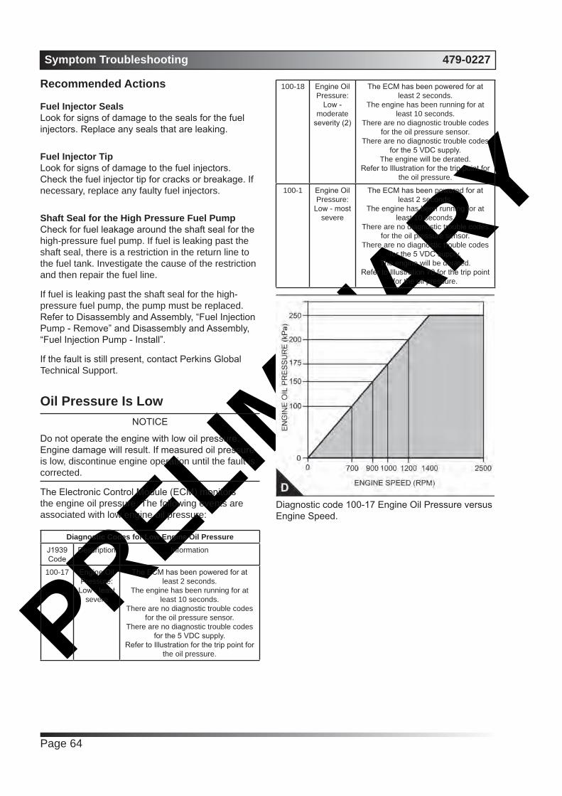
PRELIMIN
ARYSymptom Troubleshooting 479-0227
Page 64
Recommended Actions
Fuel Injector SealsLook for signs of damage to the seals for the fuel injectors. Replace any seals that are leaking.
Fuel Injector TipLook for signs of damage to the fuel injectors. Check the fuel injector tip for cracks or breakage. If necessary, replace any faulty fuel injectors.
Shaft Seal for the High Pressure Fuel PumpCheck for fuel leakage around the shaft seal for the high-pressure fuel pump. If fuel is leaking past the shaft seal, there is a restriction in the return line to the fuel tank. Investigate the cause of the restriction and then repair the fuel line.
If fuel is leaking past the shaft seal for the high- pressure fuel pump, the pump must be replaced. Refer to Disassembly and Assembly, “Fuel Injection Pump - Remove” and Disassembly and Assembly, “Fuel Injection Pump - Install”.
If the fault is still present, contact Perkins Global Technical Support.
Oil Pressure Is LowNOTICE
Do not operate the engine with low oil pressure. Engine damage will result. If measured oil pressure is low, discontinue engine operation until the fault is corrected.
The Electronic Control Module (ECM) monitors the engine oil pressure. The following events are associated with low engine oil pressure:
Diagnostic Codes for Low Engine Oil PressureJ1939 Code
Description Information
100-17 Engine Oil Pressure: Low - least
severe
The ECM has been powered for at least 2 seconds.
The engine has been running for at least 10 seconds.
There are no diagnostic trouble codes for the oil pressure sensor.
There are no diagnostic trouble codes for the 5 VDC supply.
Refer to Illustration for the trip point for the oil pressure.
100-18 Engine Oil Pressure:
Low - moderate
severity (2)
The ECM has been powered for at least 2 seconds.
The engine has been running for at least 10 seconds.
There are no diagnostic trouble codes for the oil pressure sensor.
There are no diagnostic trouble codes for the 5 VDC supply.
The engine will be derated.Refer to Illustration for the trip point for
the oil pressure.
100-1 Engine Oil Pressure:
Low - most severe
The ECM has been powered for at least 2 seconds.
The engine has been running for at least 10 seconds.
There are no diagnostic trouble codes for the oil pressure sensor.
There are no diagnostic trouble codes for the 5 VDC supply.
The engine will be derated.Refer to Illustration 70 for the trip point
for the oil pressure.
Diagnostic code 100-17 Engine Oil Pressure versus Engine Speed.
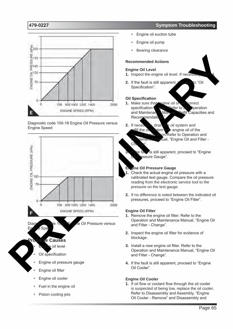
PRELIMIN
ARY479-0227 Symptom Troubleshooting
Page 65
Diagnostic code 100-18 Engine Oil Pressure versus Engine Speed
Diagnostic code 100-1 Engine Oil Pressure versus Engine Speed
Probable Causes• Engine oil level
• Oil specification
• Engine oil pressure gauge
• Engine oil filter
• Engine oil cooler
• Fuel in the engine oil
• Piston cooling jets
• Engine oil suction tube
• Engine oil pump
• Bearing clearance
Recommended Actions
Engine Oil Level1. Inspect the engine oil level. If necessary, add oil.
2. If the fault is still apparent, proceed to “Oil Specification”.
Oil Specification1. Make sure that engine oil of the correct
specification is used. Refer to the Operation and Maintenance Manual, “Refill Capacities and Recommendations”.
2. If necessary, drain the oil system and refill the oil system with engine oil of the correct specification.Refer to Operation and Maintenance Manual, “Engine Oil and Filter - Change”.
3. If the fault is still apparent, proceed to “Engine Oil Pressure Gauge”.
Engine Oil Pressure Gauge1. Check the actual engine oil pressure with a
calibrated test gauge. Compare the oil pressure reading from the electronic service tool to the pressure on the test gauge.
2. If no difference is noted between the indicated oil pressures, proceed to “Engine Oil Filter”.
Engine Oil Filter1. Remove the engine oil filter. Refer to the
Operation and Maintenance Manual, “Engine Oil and Filter - Change”.
2. Inspect the engine oil filter for evidence of blockage.
3. Install a new engine oil filter. Refer to the Operation and Maintenance Manual, “Engine Oil and Filter - Change”.
4. If the fault is still apparent, proceed to “Engine Oil Cooler”.
Engine Oil Cooler1. If oil flow or coolant flow through the oil cooler
is suspected of being low, replace the oil cooler. Refer to Disassembly and Assembly, “Engine Oil Cooler - Remove” and Disassembly and
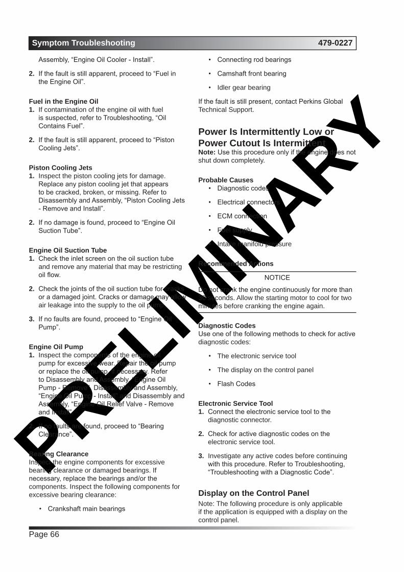
PRELIMIN
ARYSymptom Troubleshooting 479-0227
Page 66
Assembly, “Engine Oil Cooler - Install”.
2. If the fault is still apparent, proceed to “Fuel in the Engine Oil”.
Fuel in the Engine Oil1. If contamination of the engine oil with fuel
is suspected, refer to Troubleshooting, “Oil Contains Fuel”.
2. If the fault is still apparent, proceed to “Piston Cooling Jets”.
Piston Cooling Jets1. Inspect the piston cooling jets for damage.
Replace any piston cooling jet that appears to be cracked, broken, or missing. Refer to Disassembly and Assembly, “Piston Cooling Jets - Remove and Install”.
2. If no damage is found, proceed to “Engine Oil Suction Tube”.
Engine Oil Suction Tube1. Check the inlet screen on the oil suction tube
and remove any material that may be restricting oil flow.
2. Check the joints of the oil suction tube for cracks or a damaged joint. Cracks or damage may allow air leakage into the supply to the oil pump.
3. If no faults are found, proceed to “Engine Oil Pump”.
Engine Oil Pump 1. Inspect the components of the engine oil
pump for excessive wear. Repair the oil pump or replace the oil pump, if necessary. Refer to Disassembly and Assembly, “Engine Oil Pump - Remove”, Disassembly and Assembly, “Engine Oil Pump - Install” and Disassembly and Assembly, “Engine Oil Relief Valve - Remove and Install”.
2. If no faults are found, proceed to “Bearing Clearance”.
Bearing ClearanceInspect the engine components for excessive bearing clearance or damaged bearings. If necessary, replace the bearings and/or the components. Inspect the following components for excessive bearing clearance:
• Crankshaft main bearings
• Connecting rod bearings
• Camshaft front bearing
• Idler gear bearing
If the fault is still present, contact Perkins Global Technical Support.
Power Is Intermittently Low or Power Cutout Is IntermittentNote: Use this procedure only if the engine does not shut down completely.
Probable Causes• Diagnostic codes
• Electrical connectors
• ECM connection
• Fuel supply
• Intake manifold pressure
Recommended Actions
NOTICE
Do not crank the engine continuously for more than 30 seconds. Allow the starting motor to cool for two minutes before cranking the engine again.
Diagnostic CodesUse one of the following methods to check for active diagnostic codes:
• The electronic service tool
• The display on the control panel
• Flash Codes
Electronic Service Tool1. Connect the electronic service tool to the
diagnostic connector.
2. Check for active diagnostic codes on the electronic service tool.
3. Investigate any active codes before continuing with this procedure. Refer to Troubleshooting, “Troubleshooting with a Diagnostic Code”.
Display on the Control PanelNote: The following procedure is only applicable if the application is equipped with a display on the control panel.
PRELIMIN
ARY479-0227 Symptom Troubleshooting
Page 67
1. Check the display on the control panel for active diagnostic codes.
2. Troubleshoot any active codes before continuing with this procedure. Refer to Troubleshooting, “Troubleshooting with a Diagnostic Code”.
Flash CodesNote: The following procedure is only applicable if the machine is equipped with the appropriate warning lamps.
1. Check the warning lamps on the control panel for flash codes. Flash codes are explained in Troubleshooting, “Flash Codes”.
2. If any flash codes are displayed, troubleshoot the codes before continuing with this procedure. Refer to Troubleshooting, “Troubleshooting with a Diagnostic Code”.
Electrical Connectors1. Refer to Troubleshooting, “Electrical Connectors
- Inspect”.
2. Repair the electrical connectors or replace the electrical connectors.
3. Ensure that all the connector seals are in place and that the connectors have been correctly installed.
4. Ensure that the repairs have eliminated the fault. If the fault has not been eliminated proceed to “ECM Connection”.
ECM Connection1. Check that the P2/J2 connector is correctly fitted.
2. Check that the P1/J1 connector is correctly fitted.
3. If a fault is suspected with the ECM power and ground connections, refer to Troubleshooting, “Ignition Keyswitch Circuit and Battery Supply Circuit - Test”.
4. Verify that the ECM connections for the power and ground connections at the fuel pump are correctly connected.
5. Repair any faults and ensure that the faults have been eliminated.
6. If the repairs do not eliminate the faults, proceed to “Fuel Supply”.
Valve Lash Is ExcessiveProbable Causes
• Lubrication
• Valve train components
Recommended Actions
Lubrication1. Ensure that the engine oil pressure is
satisfactory. Low engine oil pressure can cause excessive component wear.
2. Remove the valve mechanism cover. Refer to Disassembly and Assembly, “Valve Mechanism Cover - Remove and Install” for the correct procedure.
3. Crank the engine and check the lubrication in the valve compartment. Ensure that there is adequate engine oil flow in the valve compartment. The passages for the engine oil must be clean.
Note: Do not run the engine without the valve mechanism cover.
Valve Train Components1. Check the hydraulic lifters for correct operation.
Refer to Systems Operation, Testing, and Adjusting, “Engine Valve Lash - Inspect”.
2. Inspect the following components of the valve train. Refer to Disassembly and Assembly for any components that must be removed for inspection.
• Rocker arms
• Valve bridges
• Pushrods
• Hydraulic lifters
• Camshaft
• Valve stems
• Rocker shaft
3. Check the components for the following conditions: abnormal wear, excessive wear, straightness and cleanliness. If necessary, use new parts for replacement.
Note: If the camshaft is replaced, new valve lifters must also be used.

PRELIMIN
ARYSymptom Troubleshooting 479-0227
Page 68

PRELIMIN
ARY479-0227 Troubleshooting with Codes
Page 69
Troubleshooting with Codes
CodesThe following table lists all the J1939 codes for the engine. The table includes a description for each code and the recommended troubleshooting procedure that must be performed.
SPN FMI Description630 2 Calibration Memory : Erratic, Intermittent, or Incorrect
100 17 Engine Oil Pressure : Data Low - Least Severe (1)
100 18 Engine Oil Pressure : Data Low - Moderately Severe (2)
100 1 Engine Oil Pressure : Data Low - Most Severe (3)
190 15 Engine Speed : Data High - Least Severe (1)
190 0 Engine Speed : Data High - Most Severe (3)
110 15 Engine Coolant Temperature : Data High - Least Severe (1)
110 16 Engine Coolant Temperature : Data High - Moderately Severe (2)
110 0 Engine Coolant Temperature : Data High - Most Severe (3)
105 15 Engine Intake Manifold #1 Temperature : Data High - Least Severe (1)
105 16 Engine Intake Manifold #1 Temperature : Data High - Moderately Severe (2)
105 0 Engine Intake Manifold #1 Temperature : Data High - Most Severe (3)
190 8 Engine Speed : Abnormal Frequency, Pulse Width, or Period
723 8 Engine Speed Sensor #2 : Abnormal Frequency, Pulse Width, or Period
168 2 Battery Potential / Power Input #1 : Erratic, Intermittent, or Incorrect
168 3 Battery Potential / Power Input #1 : Voltage Above Normal
168 4 Battery Potential / Power Input #1 : Voltage Below Normal
3509 3 Sensor Supply Voltage 1 : Voltage Above Normal
3509 4 Sensor Supply Voltage 1 : Voltage Below Normal
3510 3 Sensor Supply Voltage 2 : Voltage Above Normal
3510 4 Sensor Supply Voltage 2 : Voltage Below Normal
678 3 ECU 8 Volts DC Supply : Voltage Above Normal
678 4 ECU 8 Volts DC Supply : Voltage Below Normal
105 3 Engine Intake Manifold #1 Temperature : Voltage Above Normal
105 4 Engine Intake Manifold #1 Temperature : Voltage Below Normal
110 3 Engine Coolant Temperature : Voltage Above Normal
110 4 Engine Coolant Temperature : Voltage Below Normal
3563 3 Engine Intake Manifold #1 Absolute Pressure : Voltage Above Normal
3563 4 Engine Intake Manifold #1 Absolute Pressure : Voltage Below Normal
3563 13 Engine Intake Manifold #1 Absolute Pressure : Calibration Required
100 3 Engine Oil Pressure : Voltage Above Normal
100 4 Engine Oil Pressure : Voltage Below Normal
100 13 Engine Oil Pressure : Calibration Required
174 3 Engine Fuel Temperature 1 : Voltage Above Normal
174 4 Engine Fuel Temperature 1 : Voltage Below Normal
157 16 Engine Injector Metering Rail #1 Pressure : Data High - Moderately Severe (2)
157 18 Engine Injector Metering Rail #1 Pressure : Data Low - Moderately Severe (2)
157 3 Engine Injector Metering Rail #1 Pressure : Voltage Above Normal
157 4 Engine Injector Metering Rail #1 Pressure : Voltage Below Normal

PRELIMIN
ARYTroubleshooting with Codes 479-0227
Page 70
108 3 Barometric Pressure : Voltage Above Normal
108 4 Barometric Pressure : Voltage Below Normal
108 13 Barometric Pressure : Calibration Required
637 11 Engine Timing Sensor : Other Failure Mode
651 2 Engine Injector Cylinder #01 : Erratic, Intermittent, or Incorrect
652 2 Engine Injector Cylinder #02 : Erratic, Intermittent, or Incorrect
653 2 Engine Injector Cylinder #03 : Erratic, Intermittent, or Incorrect
654 2 Engine Injector Cylinder #04 : Erratic, Intermittent, or Incorrect
655 2 Engine Injector Cylinder #05 : Erratic, Intermittent, or Incorrect
656 2 Engine Injector Cylinder #06 : Erratic, Intermittent, or Incorrect
5571 0 High Pressure Common Rail Fuel Pressure Relief Valve : Data High - Most Severe (3)
1239 0 Engine Fuel Leakage 1 : Data High - Most Severe (3)
174 15 Engine Fuel Temperature 1 : Data High - Least Severe (1)
174 16 Engine Fuel Temperature 1 : Data High - Moderately Severe (2)
1076 5 Engine Fuel Injection Pump Fuel Control Valve : Current Below Normal
1076 6 Engine Fuel Injection Pump Fuel Control Valve : Current Above Normal
676 6 Engine Glow Plug Relay : Current Above Normal
1075 5 Engine Electric Lift Pump for Engine Fuel Supply : Current Below Normal
1075 6 Engine Electric Lift Pump for Engine Fuel Supply : Current Above Normal
651 5 Engine Injector Cylinder #01 : Current Below Normal
652 5 Engine Injector Cylinder #02 : Current Below Normal
653 5 Engine Injector Cylinder #03 : Current Below Normal
654 5 Engine Injector Cylinder #04 : Current Below Normal
655 5 Engine Injector Cylinder #05 : Current Below Normal
656 5 Engine Injector Cylinder #06 : Current Below Normal
651 6 Engine Injector Cylinder #01 : Current Above Normal
652 6 Engine Injector Cylinder #02 : Current Above Normal
653 6 Engine Injector Cylinder #03 : Current Above Normal
654 6 Engine Injector Cylinder #04 : Current Above Normal
655 6 Engine Injector Cylinder #05 : Current Above Normal
656 6 Engine Injector Cylinder #06 : Current Above Normal
1188 5 Engine Turbocharger 1 Wastegate Drive : Current Below Normal
1188 6 Engine Turbocharger 1 Wastegate Drive : Current Above Normal
631 2 Calibration Module : Erratic, Intermittent, or Incorrect
639 9 J1939 Network #1 : Abnormal Update Rate
91 3 Accelerator Pedal Position #1 : Voltage Above Normal
91 4 Accelerator Pedal Position #1 : Voltage Below Normal
91 8 Accelerator Pedal Position #1 : Abnormal Frequency, Pulse Width, or Period
28 3 Accelerator Pedal Position #3 : Voltage Above Normal
28 4 Accelerator Pedal Position #3 : Voltage Below Normal
970 31 Engine Auxiliary Engine Shutdown Switch : Condition Exists
677 6 Engine Starter Motor Relay : Current Above Normal
677 5 Engine Starter Motor Relay : Current Below Normal
1664 31 Engine Automatic Start Failed : Condition Exists
111 17 Engine Coolant Level : Data Low - Least Severe (1)
111 18 Engine Coolant Level : Data Low - Moderately Severe (2)
111 1 Engine Coolant Level : Data Low - Most Severe (3)
109 3 Engine Coolant Pressure : Voltage Above Normal
109 4 Engine Coolant Pressure : Voltage Below Normal

PRELIMIN
ARY479-0227 Troubleshooting with Codes
Page 71
109 15 Engine Coolant Pressure : Data High - Least Severe (1)
109 16 Engine Coolant Pressure : Data High - Moderately Severe (2)
109 0 Engine Coolant Pressure : Data High - Most Severe (3)
97 3 Water In Fuel Indicator : Voltage Above Normal
97 4 Water In Fuel Indicator : Voltage Below Normal
97 15 Water In Fuel Indicator : Data High - Least Severe (1)
97 16 Water In Fuel Indicator : Data High - Moderately Severe (2)
2434 3 Engine Exhaust Exhaust Gas Temperature - Left Manifold : Voltage Above Normal
2434 4 Engine Exhaust Exhaust Gas Temperature - Left Manifold : Voltage Below Normal
173 15 Engine Exhaust Gas Temperature : Data High - Least Severe (1)
173 16 Engine Exhaust Gas Temperature : Data High - Moderately Severe (2)
173 0 Engine Exhaust Gas Temperature : Data High - Most Severe (3)
2435 3 Seawater Pump Outlet Pressure : Voltage Above Normal
2435 4 Seawater Pump Outlet Pressure : Voltage Below Normal
2435 17 Seawater Pump Outlet Pressure : Data Low - Least Severe (1)
5417 3 Fuel Filter (Suction Side) Intake Pressure : Voltage Above Normal
5417 4 Fuel Filter (Suction Side) Intake Pressure : Voltage Below Normal
1381 3 Engine Fuel Supply Pump Inlet Pressure : Voltage Above Normal
1381 4 Engine Fuel Supply Pump Inlet Pressure : Voltage Below Normal
94 3 Engine Fuel Delivery Pressure : Voltage Above Normal
94 4 Engine Fuel Delivery Pressure : Voltage Below Normal
5579 3 Engine Filtered Fuel Delivery Pressure : Voltage Above Normal
5579 4 Engine Filtered Fuel Delivery Pressure : Voltage Below Normal
1382 15 Engine Fuel Filter (suction side) Differential Pressure : Data High - Least Severe (1)
95 15 Engine Fuel Filter Differential Pressure : Data High - Least Severe (1)
1208 3 Engine Pre-filter Oil Pressure : Voltage Above Normal
1208 4 Engine Pre-filter Oil Pressure : Voltage Below Normal
99 15 Engine Oil Filter Differential Pressure : Data High - Least Severe (1)
99 16 Engine Oil Filter Differential Pressure : Data High - Moderately Severe (2)
96 3 Fuel Level : Voltage Above Normal
96 4 Fuel Level : Voltage Below Normal
96 17 Fuel Level : Data Low - Least Severe (1)
175 15 Engine Oil Temperature 1 : Data High - Least Severe (1)
175 16 Engine Oil Temperature 1 : Data High - Moderately Severe (2)
175 0 Engine Oil Temperature 1 : Data High - Most Severe (3)
175 3 Engine Oil Temperature 1 : Voltage Above Normal
175 4 Engine Oil Temperature 1 : Voltage Below Normal
1239 31 Engine Fuel Leakage 1 : Condition Exists
1237 31 Engine Shutdown Override Switch : Condition Exists
971 31 Engine Derate Switch : Condition Exists
PRELIMIN
ARYTroubleshooting with Codes 479-0227
Page 72

PRELIMIN
ARY479-0227 Troubleshooting with an Event Code
Page 73
Troubleshooting with an Event Code
Event CodesAn event code alerts the operator to an abnormal engine operating condition such as low oil pressure or high coolant temperature. As this engine normally reports faults as J1939 codes, event codes are only identifiable by the Failure Mode Identifier (FMI). The FMI is the second element of the fault code. All events are identified by the following FMIs:
The Electronic Control Module (ECM) can log events. Logged events usually indicate a mechanical fault instead of an electronic system fault or the engine is operating outside the design specification.
Note: If a diagnostic code has already been logged, any associated event code to that fault will not be logged.
Note: If an event code is already active, a diagnostic code that is associated with the same sensor will not be active.
Active Event CodesAn active event code represents a fault with engine operation. Correct the fault as soon as possible. Active event codes are listed in ascending numerical order. The code with the lowest number is listed first. Event codes will cause the warning lamp to illuminate and the event will be logged.
The following Illustration is an example of the operating range of an oil temperature sensor. Do not use the Illustration to troubleshoot the oil temperature sensor.
Example of the typical operating range of a sensor
(1). This area represents the normal operating range of the engine parameter.
(2). In these areas, the engine is operating in an unsafe operating range of the monitored parameter. An event code will be generated for the monitored parameter. The sensor circuit does not have an electronic fault.
(3). In these areas, the signal from the sensor is outside of the operating range of the sensor. The sensor circuit has an electronic fault. A diagnostic code will be generated for the sensor circuit. Refer to Troubleshooting, “Self Diagnostics” for additional information on diagnostic codes.
The following format is used for event codes:
“XXXX-YY Description of the event”
The “XXXX” represents a System Parameter Number for the event code. The “-YY” represents FMI for the severity of the event. The FMI is followed by a description of the event. Refer to the following example:
PRELIMIN
ARYTroubleshooting with an Event Code 479-0227
Page 74
“100-17 Engine Oil Pressure : Low - Least Severe (1)”
In this example, the number “-17” indicates the severity of the event. The ECM has three levels of response to events:
Level (1) – This level can be referred to as the “Warning Level” . This condition represents a serious problem with engine operation. However, this condition does not require the engine to derate or shut down. The warning lamp will come on.
Level (2) – This level can be referred to as the “Derate Level” . For this condition, the ECM will derate the engine in order to help prevent possible engine damage. The warning lamp will flash.
Level (3) – This level can be referred to as the “Shutdown Level” . A “Level 3” event code will be logged in the ECM and the engine will shut down if the shutdown feature is enabled. The warning lamp will flash and the shutdown lamp will come on.
Responses to certain events may be programmed into the ECM. Refer to Troubleshooting, “System Configuration Parameters”.
Logged Event CodesWhen the ECM generates an event code, the ECM logs the code in permanent memory. The ECM has an internal diagnostic clock. The ECM will record the following information when an event code is generated:
• The hour of the first occurrence of the code
• The hour of the last occurrence of the code
• The number of occurrences of the code
Logged events are listed in chronological order. The most recent event code is listed first.
This information can be helpful for troubleshooting intermittent faults. Logged codes can also be used to review the performance of the engine.
Clearing Event CodesA code is cleared from memory when one of the following conditions occur:
• The code does not recur for 100 hours.
• A new code is logged and there are already ten codes in memory. In this case, the oldest code is cleared.
• The service technician manually clears the code.
Always clear logged event codes after investigating and correcting the fault which generated the code.
TroubleshootingFor basic troubleshooting of the engine, perform the following steps in order to diagnose a malfunction:
1. Obtain the following information about the complaint from the operator:
• The event and the time of the event
• Determine the conditions for the event. The conditions will include the engine rpm and the load.
• Determine if there are any systems that were installed by the dealer or by the customer that could cause the event.
• Determine whether any additional events occurred.
2. Verify that the complaint is not due to normal engine operation. Verify that the complaint is not due to error of the operator.
3. Refer to Troubleshooting, “Diagnostic Trouble Codes”. Perform the troubleshooting procedure that is shown against the reported code.
If these steps do not resolve the fault, identify the procedures in this manual that best describe the event. Check each probable cause according to the tests that are recommended.
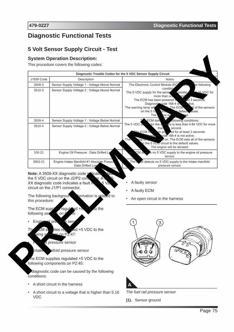
PRELIMIN
ARY479-0227 Diagnostic Functional Tests
Page 75
Diagnostic Functional Tests
5 Volt Sensor Supply Circuit - TestSystem Operation Description:This procedure covers the following codes:
Diagnostic Trouble Codes for the 5 VDC Sensor Supply CircuitJ1939 Code Description Notes
3509-3 Sensor Supply Voltage 1 : Voltage Above Normal The Electronic Control Module (ECM) detects the following conditions:
The 5 VDC supply for the sensors is greater than 5.16 VDC for more than one second.
The ECM has been powered for at least 3 seconds.Diagnostic code 168-4 is not active.
The warning lamp will come on. The ECM sets all of the sensors on the 5 VDC circuit to the default values.
The engine will be derated.
3510-3 Sensor Supply Voltage 2 : Voltage Above Normal
3509-4 Sensor Supply Voltage 1 : Voltage Below Normal The ECM detects the following conditions:The 5 VDC supply for the sensors is less than 4.84 VDC for more
than one second.The ECM has been powered for at least 3 seconds.
Diagnostic code 168-4 is not active.The warning lamp will come on. The ECM sets all of the sensors
on the 5 VDC circuit to the default values.The engine will be derated.
3510-4 Sensor Supply Voltage 2 : Voltage Below Normal
100-21 Engine Oil Pressure : Data Drifted Low The ECM detects no 5 VDC supply to the engine oil pressure sensor.
3563-21 Engine Intake Manifold #1 Absolute Pressure : Data Drifted Low
The ECM detects no 5 VDC supply to the intake manifold pressure sensor.
Note: A 3509-XX diagnostic code indicates a fault in the 5 VDC circuit on the J2/P2 connector. A 3510-XX diagnostic code indicates a fault in the 5 VDC circuit on the J1/P1 connector.
The following background information is related to this procedure:
The ECM supplies regulated +5 VDC to the following sensors on P2:46:
• Engine oil pressure sensor
The ECM supplies regulated +5 VDC to the following sensors on P2:47:
• Fuel rail pressure sensor
• Intake manifold pressure sensor
The ECM supplies regulated +5 VDC to the following components on P2:45:
A diagnostic code can be caused by the following conditions:
• A short circuit in the harness
• A short circuit to a voltage that is higher than 5.16 VDC
• A faulty sensor
• A faulty ECM
• An open circuit in the harness
The fuel rail pressure sensor
(1). Sensor ground
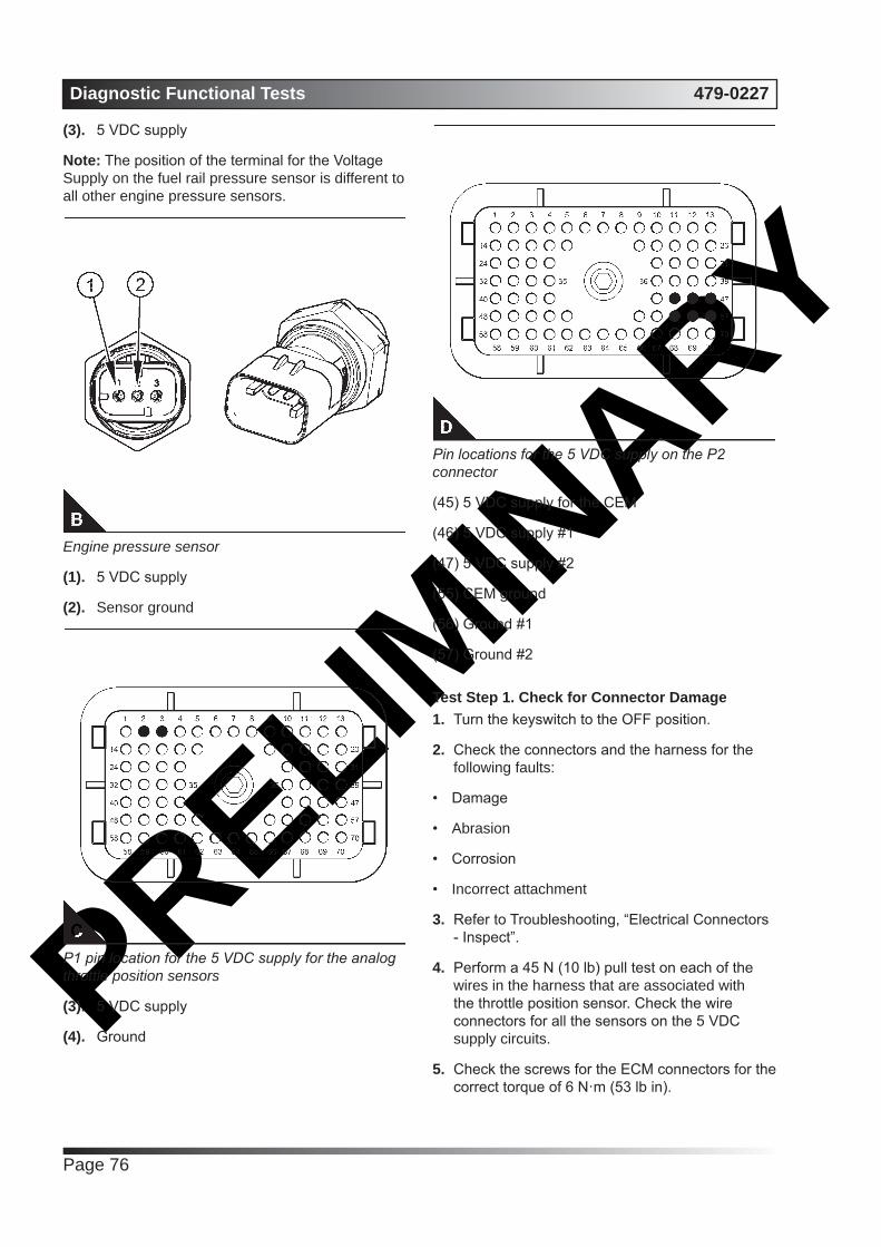
PRELIMIN
ARYDiagnostic Functional Tests 479-0227
Page 76
(3). 5 VDC supply
Note: The position of the terminal for the Voltage Supply on the fuel rail pressure sensor is different to all other engine pressure sensors.
Engine pressure sensor
(1). 5 VDC supply
(2). Sensor ground
P1 pin location for the 5 VDC supply for the analog throttle position sensors
(3). 5 VDC supply
(4). Ground
Pin locations for the 5 VDC supply on the P2 connector
(45) 5 VDC supply for the CEM
(46) 5 VDC supply #1
(47) 5 VDC supply #2
(55) CEM ground
(56) Ground #1
(57) Ground #2
Test Step 1. Check for Connector Damage1. Turn the keyswitch to the OFF position.
2. Check the connectors and the harness for the following faults:
• Damage
• Abrasion
• Corrosion
• Incorrect attachment
3. Refer to Troubleshooting, “Electrical Connectors - Inspect”.
4. Perform a 45 N (10 lb) pull test on each of the wires in the harness that are associated with the throttle position sensor. Check the wire connectors for all the sensors on the 5 VDC supply circuits.
5. Check the screws for the ECM connectors for the correct torque of 6 N·m (53 lb in).

PRELIMIN
ARY479-0227 Diagnostic Functional Tests
Page 77
Expected Result:The connectors and the harness should be free of the following faults: damage, abrasion, corrosion and incorrect attachment.
Results:• No faults found Proceed to Test Step 2.
• Found damage, abrasion, corrosion, or incorrect attachment
RepairRepair the connectors or the harness and/or replace the connectors or the harness.
Use the electronic service tool in order to clear all logged diagnostic codes and then verify that the repair eliminates the fault.
Test Step 2. Check for Active Diagnostic Codes1. Connect the electronic service tool to the
diagnostic connector.
2. Turn the keyswitch to the ON position.
3. Use the electronic service tool in order to monitor the diagnostic codes. Check and record any active diagnostic codes.
Note: Wait at least 15 seconds in order for the diagnostic codes to become active.
Results:• Diagnostic code 3509-4 or 3510-4 is active
Proceed to Test Step 4.
• Diagnostic code 3509-3 or 3510-3 is active Proceed to Test Step 8.
• An XXXX-21 diagnostic code is active Proceed to Test Step 3.
• No 5 VDC sensor supply circuit diagnostic codes are active Proceed to Test Step 10.
Test Step 3. Measure the Sensor Supply Voltage1. Turn the keyswitch to the OFF position.
2. Disconnect the sensor that relates to the active XXXX-21 code from the engine harness.
3. Turn the keyswitch to the ON position.
4. Measure the voltage at the connector for the sensor from the terminal for the 5 VDC Supply to the sensor common terminal.
Results:• The voltage from the terminal for the 5 VDC
supply to the sensor common terminal measures 4.84 to 5.16 VDC. – The sensor supply voltage is correct.
RepairPerform the following repair:
1. Temporarily connect a new sensor to the harness but do not install the new sensor in the engine.
2. Use the electronic service tool to verify that the replacement sensor eliminates the fault.
3. If the diagnostic code is eliminated, install the replacement sensor.
4. Use the electronic service tool to clear the logged diagnostic codes.
• The sensor supply voltage is out of the nominal range. – The fault is in the harness.
RepairPerform the following repair:
1. Repair the faulty harness or replace the faulty harness.
2. Use the electronic service tool in order to clear all logged diagnostic codes and then verify that the repair eliminates the fault.
Test Step 4. Disconnect the Sensors1. Turn the keyswitch to the ON position.
2. Use the electronic service tool in order to monitor the diagnostic codes.
3. If a 3510-4 diagnostic code is displayed, disconnect the analog throttle position sensors (if equipped) one at a time.
4. If a 3509-4 diagnostic code is displayed, disconnect the sensors on the 5 VDC supply circuits on the J2/P2 connector one at a time. Wait for 30 seconds after each sensor is disconnected.
Note: Diagnostic code 3509-4 or 3510-4 will become inactive when the sensor that caused the 5 VDC diagnostic code is disconnected.
5. Ensure that all the sensors on the 5 VDC supply circuits are disconnected.
PRELIMIN
ARYDiagnostic Functional Tests 479-0227
Page 78
Expected Result:The 5 VDC diagnostic code is not active when all of the sensors are disconnected.
Results:• Diagnostic code 3509-4 and diagnostic code
3510- 4 are not active when all of the sensors are disconnected.
RepairReconnect all of the sensors except the suspect sensor. Proceed to Test Step 5.
• Diagnostic code 3509-4 or 3510-4 is still active.
RepairLeave all of the sensors disconnected. Proceed to Test Step 6.
Test Step 5. Install a New Sensor1. Install the connector on a replacement sensor.
Do not install the replacement sensor on the engine.
2. Use the electronic service tool in order to monitor the diagnostic codes.
Expected Result:The following diagnostic codes are not active:
• 3509-3Sensor Supply Voltage 1 : Voltage Above Normal
• 3510-3Sensor Supply Voltage 2 : Voltage Above Normal
• 3509-4Sensor Supply Voltage 1 : Voltage Below Normal
• 3510-4Sensor Supply Voltage 2 : Voltage Below Normal
Results:• No 5 VDC diagnostic codes are active.
RepairUse the electronic service tool in order to clear all logged diagnostic codes. Remove the suspect sensor and then install the replacement sensor. Install the connector on the sensor.
Verify that the repair eliminates the fault.
• A 5 VDC diagnostic code is still active.
RepairDo not use the new sensor. Proceed to Test Step 6.
Test Step 6. Remove the Pins for the 5 VDC Supply from the ECM Connector and Check for Active Diagnostic Codes1. Turn the keyswitch to the OFF position.
2. Connect the electronic service tool to the diagnostic connector.
3. Check the ECM connectors for corrosion and moisture.
4. For a 3509-4 diagnostic code, perform the following steps:
a. Disconnect the P2 connector from the ECM.
b. Temporarily remove pins P2:45, P2:46 and P2:47.
c. Reconnect connector P2 to the ECM.
5. For a 3510-4 diagnostic code, perform the following steps:
a. Disconnect the P1 connector from the ECM.
b. Temporarily remove pin P1:2.
c. Reconnect connector P1 to the ECM.
5. Turn the keyswitch to the ON position.
6. Check for active diagnostic codes on the electronic service tool.
Results:• Diagnostic code 3510-4 was previously active
and is no longer active – Replace all wires on the P1 connector to the original configuration. Proceed to Test Step 9.
• Diagnostic code 3509-4 was previously active and is no longer active – Do not replace pins P2:45, P2:46 and P2:47. Proceed to Test Step 7.
• Not OK – The 5 VDC diagnostic codes are still active.
RepairPerform the following repair:
1. Make sure that the latest flash file for the application is installed in the ECM. Refer to Troubleshooting, “Flash Programming”.

PRELIMIN
ARY479-0227 Diagnostic Functional Tests
Page 79
2. Contact Perkins Global Technical Support.
Note: This consultation can greatly reduce the repair time.
3. If Perkins Global Technical Support recommend the use of a test ECM, install a test ECM. Refer to Troubleshooting, “Replacing the ECM”.
4. Use the electronic service tool to recheck the system for active diagnostic codes.
5. If the fault is resolved with the test ECM, reconnect the suspect ECM.
6. If the fault returns with the suspect ECM, replace the ECM.
7. Use the electronic service tool in order to clear all logged diagnostic codes and then verify that the repair eliminates the fault.
Test Step 7. Reconnect the pins for the 5 VDC supply one at a time and check for active diagnostic codes1. Disconnect the P2 connector from the ECM.
2. Replace one of the following pins:
• P2:45
• P2:46
• P2:47
3. Reconnect the P2 connector to the ECM.
4. Check for active diagnostic codes on the electronic service tool.
Results:• A 3509-XX diagnostic code is active. Proceed to
Test Step 9.
• No 3509-XX diagnostic codes are active. Proceed to Test Step 7.
Test Step 8. Check the 5 VDC Supply from the ECM1. For a 3510-3 diagnostic code, perform the
following steps:
a. Disconnect the P1 connector from the ECM.
b. Check the ECM connector for corrosion and moisture. Refer to Troubleshooting, “Electrical Connectors - Inspect”.
c. Remove the wire from P1:2.
d. Install a jumper wire to P1:2.
e. Measure the voltage from the end of the jumper wire to P1:3.
2. B. For a 3509-3 diagnostic code, perform the following steps:
a. Disconnect the P2 connector from the ECM.
b. Check the ECM connector for corrosion and moisture. Refer to Troubleshooting, “Electrical Connectors - Inspect”.
c. Remove the wires from P2:46 and P2:47.
d. Install a jumper wire to P2:46.
e. Measure the voltage from the end of the jumper wire to P2:56.
f. Install a jumper wire to P2:47.
g. Measure the voltage from the end of the jumper wire to P2:57.
Expected Result:The measured voltages should be 5.0 ± 0.16 VDC.
Results:• The voltage is within the expected range.
Proceed to Test Step 9.
• The voltage is not within the expected range.
RepairPerform the following repair:
1. Make sure that the latest flash file for the application is installed in the ECM. Refer to Troubleshooting, “Flash Programming”.
2. Contact Perkins Global Technical Support.
Note: This consultation can greatly reduce the repair time.
3. If Perkins Global Technical Support recommend the use of a test ECM, install a test ECM. Refer to Troubleshooting, “Replacing the ECM”.
4. Use the electronic service tool to recheck the system for active diagnostic codes.
5. If the fault is resolved with the test ECM, reconnect the suspect ECM.
6. If the fault returns with the suspect ECM, replace the ECM.

PRELIMIN
ARYDiagnostic Functional Tests 479-0227
Page 80
7. Use the electronic service tool in order to clear all logged diagnostic codes and then verify that the repair eliminates the fault.
Test Step 9. Measure the +5 VDC Supply to the Sensor1. Turn the keyswitch to the ON position.
2. For a 3510-XX diagnostic code, perform the following steps:
a. Disconnect the analog throttle position sensors.
b. Measure the voltage between terminal A (analog throttle position sensors +5 Volts) and the engine ground for each of the analog throttle position sensors.
3. For a 3509-XX diagnostic code, perform the following steps:
a. Disconnect all of the sensors that are supplied with 5 VDC from the pin that was previously identified.
b. Measure the voltage between the terminal for the 5 VDC supply and the engine ground on the connector for each of the sensors.
Expected Result:The voltage is 5.0 ± 0.16 VDC.
Results:• OK – The +5 VDC supply is within the expected
range. Proceed to Test Step 10.
• Not OK – The voltage is greater than 5.16 VDC.
RepairCheck the +5 VDC supply wire for a short to a higher voltage source.
Repair the +5 VDC supply wire and/or replace the +5 VDC supply wire.
Use the electronic service tool in order to clear all logged diagnostic codes and then verify that the repair eliminates the fault.
• Not OK – The voltage is less than 4.84 VDC.
RepairCheck the +5 VDC supply wire for a short to ground.
Repair the +5 VDC supply wire and/or replace the
+5 VDC supply wire.
Use the electronic service tool in order to clear all logged diagnostic codes and then verify that the repair eliminates the fault.
Test Step 10. Perform the “Wiggle Test” on the Electronic Service Tool1. Select the “Wiggle Test” from the diagnostic tests
on the electronic service tool.
2. Choose the appropriate group of parameters to monitor.
3. Press the “Start” button. Wiggle the wiring harness in order to reproduce intermittent faults.
If an intermittent fault exists, the status will be highlighted and an audible beep will be heard.
Expected Result:No intermittent faults were indicated during the “Wiggle Test” .
Results• OK – No intermittent faults were found. The
harness and connectors appear to be OK. If you were sent from another procedure, return to the procedure and continue testing. If this test has resolved the fault, return the engine to service.
• Not OK – At least one intermittent fault was indicated.
RepairRepair the harness or the connector.
Use the electronic service tool in order to clearall logged diagnostic codes and then verify that the repair eliminates the fault.
CAN Data Link Circuit - TestSystem Operation Description:Use this procedure if a fault is suspected in the CAN data link.
The following background information is related to this procedure:
The CAN data link is also known as J1939 data link. The data link is an industry standard for sending data between different devices in the same application.
High speed data is transferred via the data link.
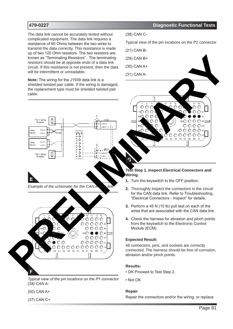
PRELIMIN
ARY479-0227 Diagnostic Functional Tests
Page 81
The data link cannot be accurately tested without complicated equipment. The data link requires a resistance of 60 Ohms between the two wires to transmit the data correctly. This resistance is made up of two 120 Ohm resistors. The two resistors are known as “Terminating Resistors” . The terminating resistors should be at opposite ends of a data link circuit. If this resistance is not present, then the data will be intermittent or unreadable.
Note: The wiring for the J1939 data link is a shielded twisted pair cable. If the wiring is damaged, the replacement type must be shielded twisted pair cable.
Example of the schematic for the CAN A data link.
Typical view of the pin locations on the P1 connector (34) CAN A-
(50) CAN A+
(37) CAN C+
(38) CAN C-
Typical view of the pin locations on the P2 connector
(21) CAN B-
(29) CAN B+
(30) CAN A+
(31) CAN A-
Test Step 1. Inspect Electrical Connectors and Wiring.1. Turn the keyswitch to the OFF position.
2. Thoroughly inspect the connectors in the circuit for the CAN data link. Refer to Troubleshooting, “Electrical Connectors - Inspect” for details.
3. Perform a 45 N (10 lb) pull test on each of the wires that are associated with the CAN data link.
4. Check the harness for abrasion and pinch points from the keyswitch to the Electronic Control Module (ECM).
Expected Result:All connectors, pins, and sockets are correctly connected. The harness should be free of corrosion, abrasion and/or pinch points.
Results:• OK Proceed to Test Step 2.
• Not OK
RepairRepair the connectors and/or the wiring, or replace
PRELIMIN
ARYDiagnostic Functional Tests 479-0227
Page 82
the connectors and/or the wiring. Ensure that all of the seals are correctly in place and ensure that the connectors are correctly connected.
Use the electronic service tool in order to clear all logged diagnostic codes and then verify that the repair eliminates the fault.
Test Step 2. Check the Data Link Terminating Resistance1. Disconnect the P1 connector and the P2
connector from the ECM.
2. Measure the resistance between the P1:34 and P1:50.
3. Measure the resistance between the P1:37 and P1:38.
4. Measure the resistance between the P2:30 and P2:31.
5. Measure the resistance between the P2:21 and P2:29.
Expected Result:The resistance is between 50 and 70 Ohms.
Results:• The resistance is between 50 and 70 Ohms –
This is the correct resistance. The fault may be in the connection to other devices on the data link. Proceed to Test Step 3.
• The resistance is less than 50 Ohms – There is a short circuit in the harness.
RepairRepair the connectors or the harness and/or replace the connectors or the harness.
Ensure that all of the seals are correctly in place and ensure that the connectors are correctly connected.
Use the electronic service tool in order to clear all logged diagnostic codes and then verify that the repair eliminates the fault.
• The resistance is between 110 and 130 Ohms – One of the terminating resistors may have failed.
RepairLocate the two terminating resistors and remove the two terminating resistors from the harness. Depending on the application, one or both of the terminating resistors may be located in other ECMs
on the data link.
Measure the resistance of the two terminating resistors.
If one of the terminating resistors is incorrect, replace the faulty terminating resistor. Proceed to Test Step 4.
• The resistance is greater than 150 Ohms – There may be a break in the harness. Proceed to Test Step 3.
Test Step 3. Check the Data Link Wiring1. Disconnect each of the connectors that connect
other devices on the data link.
2. Use a multimeter to measure the resistance between P1:50 to each of the CAN+ pins on other devices on the CAN A data link.
3. Use a multimeter to measure the resistance between P1:37 to each of the CAN+ pins on other devices on the CAN C data link.
4. Use a multimeter to measure the resistance between P2:29 to the CAN+ pin on the soot sensor module.
5. Use a multimeter to measure the resistance between P2:30 to the CAN+ pin on the diagnostic connector.
6. Use a multimeter to measure the resistance between P1:34 to each of the CAN- pins on other devices on the CAN A data link.
7. Use a multimeter to measure the resistance between P1:38 to each of the CAN- pins on other devices on the CAN C data link.
8. Use a multimeter to measure the resistance between P2:21 to the CAN- pin on the soot sensor module.
9. Use a multimeter to measure the resistance between P2:31 to the CAN- pin on the diagnostic connector.
Expected Result:The resistance of each wire is less than 2.0 Ohms.
Results:• The resistance is less than 2.0 Ohms Proceed to
Test Step 4.
• Some resistances are more than 2.0 Ohms.
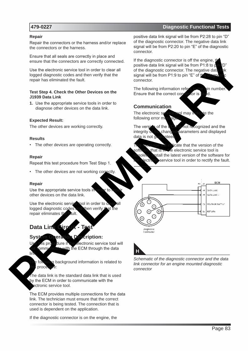
PRELIMIN
ARY479-0227 Diagnostic Functional Tests
Page 83
RepairRepair the connectors or the harness and/or replace the connectors or the harness.
Ensure that all seals are correctly in place and ensure that the connectors are correctly connected.
Use the electronic service tool in order to clear all logged diagnostic codes and then verify that the repair has eliminated the fault.
Test Step 4. Check the Other Devices on the J1939 Data Link1. Use the appropriate service tools in order to
diagnose other devices on the data link.
Expected Result:The other devices are working correctly.
Results• The other devices are operating correctly.
RepairRepeat this test procedure from Test Step 1.
• The other devices are not working correctly.
RepairUse the appropriate service tools in order to repair other devices on the data link.
Use the electronic service tool in order to clear all logged diagnostic codes and then verify that the repair eliminates the fault.
Data Link Circuit - TestSystem Operation Description:Use this procedure if the electronic service tool will not communicate with the ECM through the data link.
The following background information is related to this procedure:
The data link is the standard data link that is used by the ECM in order to communicate with the electronic service tool.
The ECM provides multiple connections for the data link. The technician must ensure that the correct connector is being tested. The connection that is used is dependent on the application.
If the diagnostic connector is on the engine, the
positive data link signal will be from P2:28 to pin “D” of the diagnostic connector. The negative data link signal will be from P2:20 to pin “E” of the diagnostic connector.
If the diagnostic connector is off the engine, the positive data link signal will be from P1:8 to pin “D” of the diagnostic connector. The negative data link signal will be from P1:9 to pin “E” of the diagnostic connector.
The following information refers to the pin number. Ensure that the correct connector is used.
CommunicationThe electronic service tool may indicate the following error message:
The version of the ECM is not recognized and the integrity of the changed parameters and displayed data is not guaranteed.
This message will indicate that the version of the software that is in the electronic service tool is obsolete. Install the latest version of the software for the electronic service tool in order to rectify the fault.
Schematic of the diagnostic connector and the data link connector for an engine mounted diagnostic connector

PRELIMIN
ARYDiagnostic Functional Tests 479-0227
Page 84
Schematic of the diagnostic connector and the data link connector for a diagnostic connector that is mounted off engine
View of the P1 pin locations for the diagnostic connector
(8) Data link +
(9) Data link -
View of the P2 pin locations for the diagnostic connector
(20) Data link -
(28) Data link +
(53) Voltage supply (diagnostic connector)
(54) Return (diagnostic connector)
Test Step 1. Inspect Electrical Connectors and Wiring1. Thoroughly inspect the following electrical
connectors:
• P1/J1 ECM connector
• P2/J2 ECM connector
• The connection for the diagnostic connector Refer to Troubleshooting, “Electrical Connectors - Inspect” for details.
2. Perform a 45 N (10 lb) pull test on each of the wires in the ECM connectors that are associated with the data link.
3. Check the screw for the ECM connectors for correct torque of 6 N·m (53 lb in).
4. Check the harness for abrasion and pinch points from the wires that connect the diagnostic connector to the ECM.
Expected Result:All connectors, pins, and sockets are correctly connected and/or inserted. The harness should be free of corrosion, abrasion and/or pinch points.
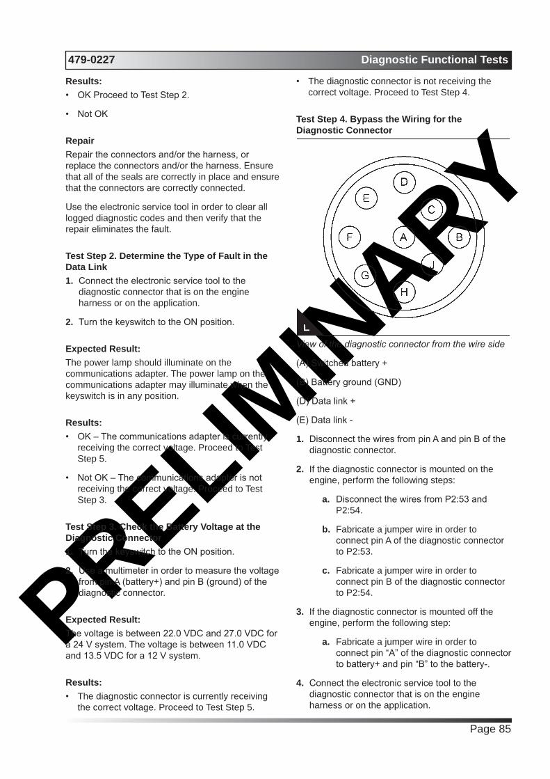
PRELIMIN
ARY479-0227 Diagnostic Functional Tests
Page 85
Results:• OK Proceed to Test Step 2.
• Not OK
RepairRepair the connectors and/or the harness, or replace the connectors and/or the harness. Ensure that all of the seals are correctly in place and ensure that the connectors are correctly connected.
Use the electronic service tool in order to clear all logged diagnostic codes and then verify that the repair eliminates the fault.
Test Step 2. Determine the Type of Fault in the Data Link1. Connect the electronic service tool to the
diagnostic connector that is on the engine harness or on the application.
2. Turn the keyswitch to the ON position.
Expected Result:The power lamp should illuminate on the communications adapter. The power lamp on the communications adapter may illuminate when the keyswitch is in any position.
Results:• OK – The communications adapter is currently
receiving the correct voltage. Proceed to Test Step 5.
• Not OK – The communications adapter is not receiving the correct voltage. Proceed to Test Step 3.
Test Step 3. Check the Battery Voltage at the Diagnostic Connector1. Turn the keyswitch to the ON position.
2. Use a multimeter in order to measure the voltage from pin A (battery+) and pin B (ground) of the diagnostic connector.
Expected Result:The voltage is between 22.0 VDC and 27.0 VDC for a 24 V system. The voltage is between 11.0 VDC and 13.5 VDC for a 12 V system.
Results:• The diagnostic connector is currently receiving
the correct voltage. Proceed to Test Step 5.
• The diagnostic connector is not receiving the correct voltage. Proceed to Test Step 4.
Test Step 4. Bypass the Wiring for the Diagnostic Connector
View of the diagnostic connector from the wire side
(A) Switched battery +
(B) Battery ground (GND)
(D) Data link +
(E) Data link -
1. Disconnect the wires from pin A and pin B of the diagnostic connector.
2. If the diagnostic connector is mounted on the engine, perform the following steps:
a. Disconnect the wires from P2:53 and P2:54.
b. Fabricate a jumper wire in order to connect pin A of the diagnostic connector to P2:53.
c. Fabricate a jumper wire in order to connect pin B of the diagnostic connector to P2:54.
3. If the diagnostic connector is mounted off the engine, perform the following step:
a. Fabricate a jumper wire in order to connect pin “A” of the diagnostic connector to battery+ and pin “B” to the battery-.
4. Connect the electronic service tool to the diagnostic connector that is on the engine harness or on the application.
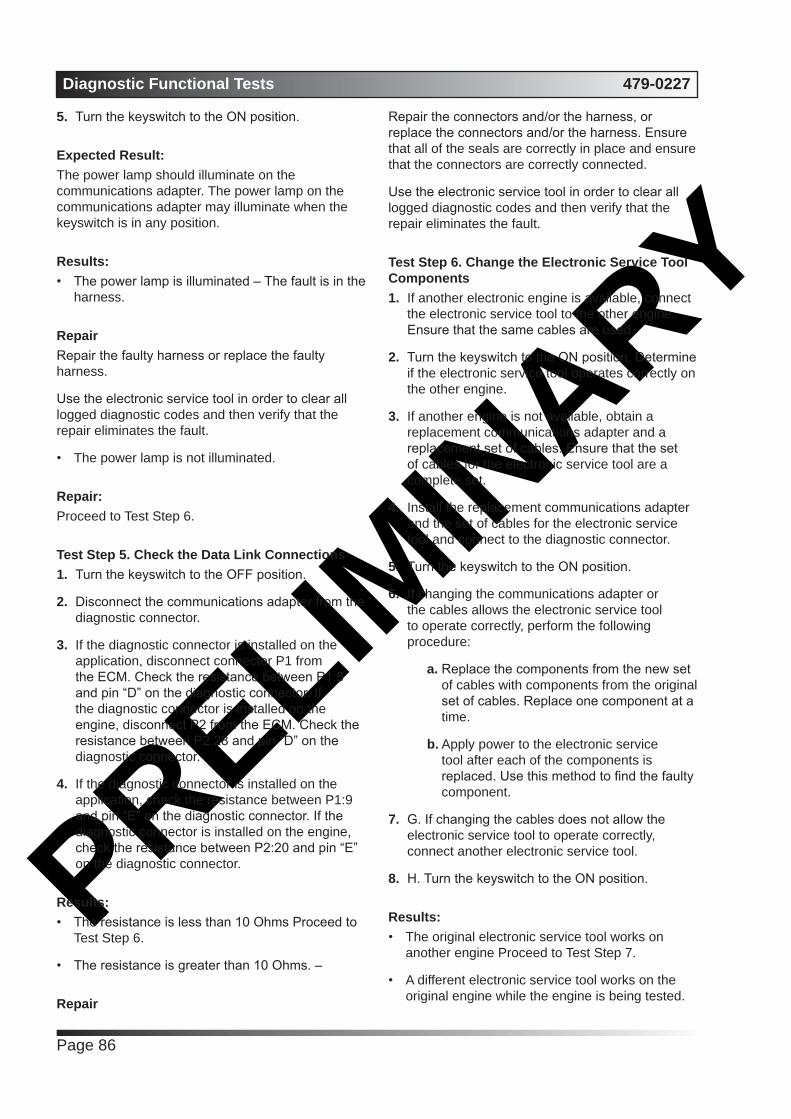
PRELIMIN
ARYDiagnostic Functional Tests 479-0227
Page 86
5. Turn the keyswitch to the ON position.
Expected Result:The power lamp should illuminate on the communications adapter. The power lamp on the communications adapter may illuminate when the keyswitch is in any position.
Results:• The power lamp is illuminated – The fault is in the
harness.
RepairRepair the faulty harness or replace the faulty harness.
Use the electronic service tool in order to clear all logged diagnostic codes and then verify that the repair eliminates the fault.
• The power lamp is not illuminated.
Repair:Proceed to Test Step 6.
Test Step 5. Check the Data Link Connections1. Turn the keyswitch to the OFF position.
2. Disconnect the communications adapter from the diagnostic connector.
3. If the diagnostic connector is installed on the application, disconnect connector P1 from the ECM. Check the resistance between P1:8 and pin “D” on the diagnostic connector. If the diagnostic connector is installed on the engine, disconnect P2 from the ECM. Check the resistance between P2:28 and pin “D” on the diagnostic connector.
4. If the diagnostic connector is installed on the application, check the resistance between P1:9 and pin “E” on the diagnostic connector. If the diagnostic connector is installed on the engine, check the resistance between P2:20 and pin “E” on the diagnostic connector.
Results:• The resistance is less than 10 Ohms Proceed to
Test Step 6.
• The resistance is greater than 10 Ohms. –
Repair
Repair the connectors and/or the harness, or replace the connectors and/or the harness. Ensure that all of the seals are correctly in place and ensure that the connectors are correctly connected.
Use the electronic service tool in order to clear all logged diagnostic codes and then verify that the repair eliminates the fault.
Test Step 6. Change the Electronic Service Tool Components1. If another electronic engine is available, connect
the electronic service tool to the other engine. Ensure that the same cables are used.
2. Turn the keyswitch to the ON position. Determine if the electronic service tool operates correctly on the other engine.
3. If another engine is not available, obtain a replacement communications adapter and a replacement set of cables. Ensure that the set of cables for the electronic service tool are a complete set.
4. Install the replacement communications adapter and the set of cables for the electronic service tool and connect to the diagnostic connector.
5. Turn the keyswitch to the ON position.
6. If changing the communications adapter or the cables allows the electronic service tool to operate correctly, perform the following procedure:
a. Replace the components from the new set of cables with components from the original set of cables. Replace one component at a time.
b. Apply power to the electronic service tool after each of the components is replaced. Use this method to find the faulty component.
7. G. If changing the cables does not allow the electronic service tool to operate correctly, connect another electronic service tool.
8. H. Turn the keyswitch to the ON position.
Results:• The original electronic service tool works on
another engine Proceed to Test Step 7.
• A different electronic service tool works on the original engine while the engine is being tested.

PRELIMIN
ARY479-0227 Diagnostic Functional Tests
Page 87
Repair:Send the faulty electronic service tool for repairs. Test Step 7. Connect an Electronic Service Tool and the ECM to another Battery
WARNING
Batteries give off flammable fumes which can explode.
To avoid injury or death, do not strike a match, cause a spark, or smoke in the vicinity of a battery.
NOTICE
Do not connect the bypass harness to the battery until the in-line fuse has been removed from the Battery + line. If the fuse is not removed before connection to the battery, a spark may result.
Note: Refer to Figure 128 for details of the bypass harness.
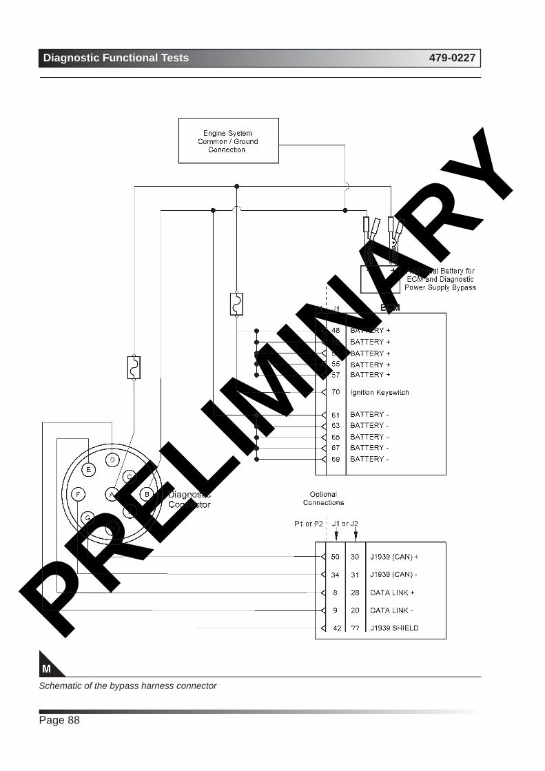
PRELIMIN
ARYDiagnostic Functional Tests 479-0227
Page 88
Schematic of the bypass harness connector

PRELIMIN
ARY479-0227 Diagnostic Functional Tests
Page 89
View of the pin locations on connector P1 for the diagnostic and data link connectors
(8) Data link +
(9) Data link -
(34) J1939 (CAN) -
(48) Battery +
(50) J1939 (CAN) +
(52) Battery +
(53) Battery +
(55) Battery +
(57) Battery +
(61) Battery ground (GND)
(63) Battery ground (GND)
(65) Battery ground (GND)
(67) Battery ground (GND)
(69) Battery ground (GND)
(70) Keyswitch
1. Connect the battery wires from the bypass harness of the electronic service tool to a different battery that is not on the engine.
Results:• The electronic service tool is operating correctly.
RepairRefer to Troubleshooting, “Ignition Keyswitch and
Battery Supply Circuit - Test”.
• The electronic service tool is not operating correctly.
Repair
1. Make sure that the latest flash file for the application is installed in the ECM. Refer to Troubleshooting, “Flash Programming”.
2. Remove all temporary jumpers and reconnect all connectors. C. Contact Perkins Global Technical Support.
Note: This consultation can greatly reduce the repair time.
3. If Perkins Global Technical Support recommend the use of a test ECM, install a test ECM. Refer to Troubleshooting, “Replacing the ECM”.
4. Use the electronic service tool to recheck the system for active diagnostic codes.
5. If the fault is eliminated with the test ECM, reconnect the suspect ECM.
6. If the fault returns with the suspect ECM, replace the ECM.
7. Use the electronic service tool in order to clear all logged diagnostic codes and then verify that the repair eliminates the fault.
ECM Memory - TestSystem Operation Description:This procedure covers the following diagnostic code:
Diagnostic Trouble Codes for ECM SoftwareJ1939 Code
Description Notes
631-2 Calibration Module : Erratic, Intermittent or
Incorrect
The Electronic Control Module (ECM) detects incorrect engine
software.If equipped, the warning light will
come on.This diagnostic code is not logged.Factory passwords are required to
clear this diagnostic code.The engine will not start.
The flash file in the ECM is from the wrong engine family.
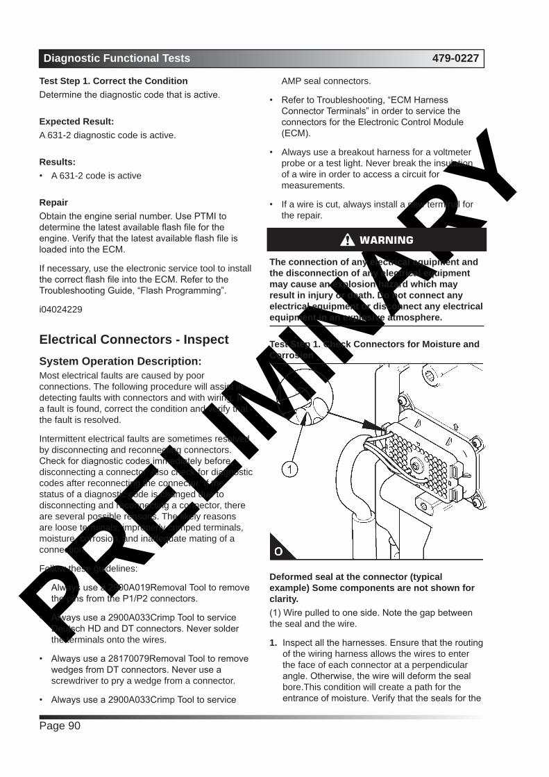
PRELIMIN
ARYDiagnostic Functional Tests 479-0227
Page 90
Test Step 1. Correct the ConditionDetermine the diagnostic code that is active.
Expected Result:A 631-2 diagnostic code is active.
Results:• A 631-2 code is active
RepairObtain the engine serial number. Use PTMI to determine the latest available flash file for the engine. Verify that the latest available flash file is loaded into the ECM.
If necessary, use the electronic service tool to install the correct flash file into the ECM. Refer to the Troubleshooting Guide, “Flash Programming”.
i04024229
Electrical Connectors - InspectSystem Operation Description:Most electrical faults are caused by poor connections. The following procedure will assist in detecting faults with connectors and with wiring. If a fault is found, correct the condition and verify that the fault is resolved.
Intermittent electrical faults are sometimes resolved by disconnecting and reconnecting connectors. Check for diagnostic codes immediately before disconnecting a connector. Also check for diagnostic codes after reconnecting the connector. If the status of a diagnostic code is changed due to disconnecting and reconnecting a connector, there are several possible reasons. The likely reasons are loose terminals, improperly crimped terminals, moisture, corrosion, and inadequate mating of a connection.
Follow these guidelines:
• Always use a 2900A019Removal Tool to remove the pins from the P1/P2 connectors.
• Always use a 2900A033Crimp Tool to service Deutsch HD and DT connectors. Never solder the terminals onto the wires.
• Always use a 28170079Removal Tool to remove wedges from DT connectors. Never use a screwdriver to pry a wedge from a connector.
• Always use a 2900A033Crimp Tool to service
AMP seal connectors.
• Refer to Troubleshooting, “ECM Harness Connector Terminals” in order to service the connectors for the Electronic Control Module (ECM).
• Always use a breakout harness for a voltmeter probe or a test light. Never break the insulation of a wire in order to access a circuit for measurements.
• If a wire is cut, always install a new terminal for the repair.
WARNING
The connection of any electrical equipment and the disconnection of any electrical equipment may cause an explosion hazard which may result in injury or death. Do not connect any electrical equipment or disconnect any electrical equipment in an explosive atmosphere.
Test Step 1. Check Connectors for Moisture and Corrosion
Deformed seal at the connector (typical example) Some components are not shown for clarity.(1) Wire pulled to one side. Note the gap between the seal and the wire.
1. Inspect all the harnesses. Ensure that the routing of the wiring harness allows the wires to enter the face of each connector at a perpendicular angle. Otherwise, the wire will deform the seal bore.This condition will create a path for the entrance of moisture. Verify that the seals for the

PRELIMIN
ARY479-0227 Diagnostic Functional Tests
Page 91
wires are sealing correctly.
2. Ensure that the sealing plugs are in place. If any of the plugs are missing, replace the plug. Ensure that the plugs are inserted correctly into the connector.
(1) A typical seal for a four-pin connector.
(1) Seal for ECM connector.
3. Disconnect the suspect connector and inspect the connector seal. Ensure that the seal is in good condition. If necessary, replace the connector.
4. Thoroughly inspect the connectors for evidence of moisture entry.
Note: Some minor seal abrasion on connector seals is normal. Minor seal abrasion will not allow the entry of moisture.
If moisture or corrosion is evident in the connector,
the source of the moisture entry must be identified and repaired. If the source of the moisture entry is not repaired, the fault will recur. Simply drying the connector will not rectify the fault. Check the following items for the possible moisture entry path:
• Missing seals
• Incorrectly installed seals
• Nicks in exposed insulation
• Improperly mated connectors
Moisture can also travel to a connector through the inside of a wire. If moisture is found in a connector, thoroughly check the connector harness for damage. Also check other connectors that share the harness for moisture.
Note: The ECM is a sealed unit. If moisture is found in an ECM connector, the ECM is not the source of the moisture. Do not replace the ECM.
Expected Result:The harness, connectors, and seals are in good condition. There is no evidence of moisture in the connectors.
Results:• The harness, connectors, and seals are in good
condition Proceed to Test Step 2.
• A fault has been found with the harness or the connectors.
RepairRepair the connectors or the wiring, as required. Ensure that all of the seals are correctly installed. Ensure that the connectors have been reattached. Ensure that all pins and sockets are free of corrosion and/or moisture before continuing with this procedure.
If corrosion is evident on the pins, sockets or the connector, use only denatured alcohol to remove the corrosion. Use a cotton swab or a soft brush to remove the corrosion.
If moisture was found in the connectors, run the engine for several minutes and check again for moisture. If moisture reappears, the moisture is wicking into the connector. Even if the moisture entry path is repaired, replacement of the wires may be necessary.
Use the electronic service tool in order to clear all logged diagnostic codes and then verify that the
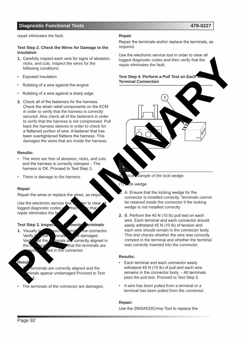
PRELIMIN
ARYDiagnostic Functional Tests 479-0227
Page 92
repair eliminates the fault.
Test Step 2. Check the Wires for Damage to the Insulation1. Carefully inspect each wire for signs of abrasion,
nicks, and cuts. Inspect the wires for the following conditions:
• Exposed insulation
• Rubbing of a wire against the engine
• Rubbing of a wire against a sharp edge
2. Check all of the fasteners for the harness. Check the strain relief components on the ECM in order to verify that the harness is correctly secured. Also check all of the fasteners in order to verify that the harness is not compressed. Pull back the harness sleeves in order to check for a flattened portion of wire. A fastener that has been overtightened flattens the harness. This damages the wires that are inside the harness.
Results:• The wires are free of abrasion, nicks, and cuts
and the harness is correctly clamped – The harness is OK. Proceed to Test Step 3.
• There is damage to the harness.
RepairRepair the wires or replace the wires, as required.
Use the electronic service tool in order to clear all logged diagnostic codes and then verify that the repair eliminates the fault.
Test Step 3. Inspect the Connector Terminals1. Visually inspect each terminal in the connector.
Verify that the terminals are not damaged. Verify that the terminals are correctly aligned in the connector and verify that the terminals are correctly located in the connector.
Results:• The terminals are correctly aligned and the
terminals appear undamaged Proceed to Test Step 4.
• The terminals of the connector are damaged.
RepairRepair the terminals and/or replace the terminals, as required.
Use the electronic service tool in order to clear all logged diagnostic codes and then verify that the repair eliminates the fault.
Test Step 4. Perform a Pull Test on Each Wire Terminal Connection
A typical example of the lock wedge.
(1) Lock wedge
1. A. Ensure that the locking wedge for the connector is installed correctly. Terminals cannot be retained inside the connector if the locking wedge is not installed correctly.
2. B. Perform the 45 N (10 lb) pull test on each wire. Each terminal and each connector should easily withstand 45 N (10 lb) of tension and each wire should remain in the connector body. This test checks whether the wire was correctly crimped in the terminal and whether the terminal was correctly inserted into the connector.
Results:• Each terminal and each connector easily
withstand 45 N (10 lb) of pull and each wire remains in the connector body. – All terminals pass the pull test. Proceed to Test Step 5.
• A wire has been pulled from a terminal or a terminal has been pulled from the connector.
Repair: Use the 2900A033Crimp Tool to replace the
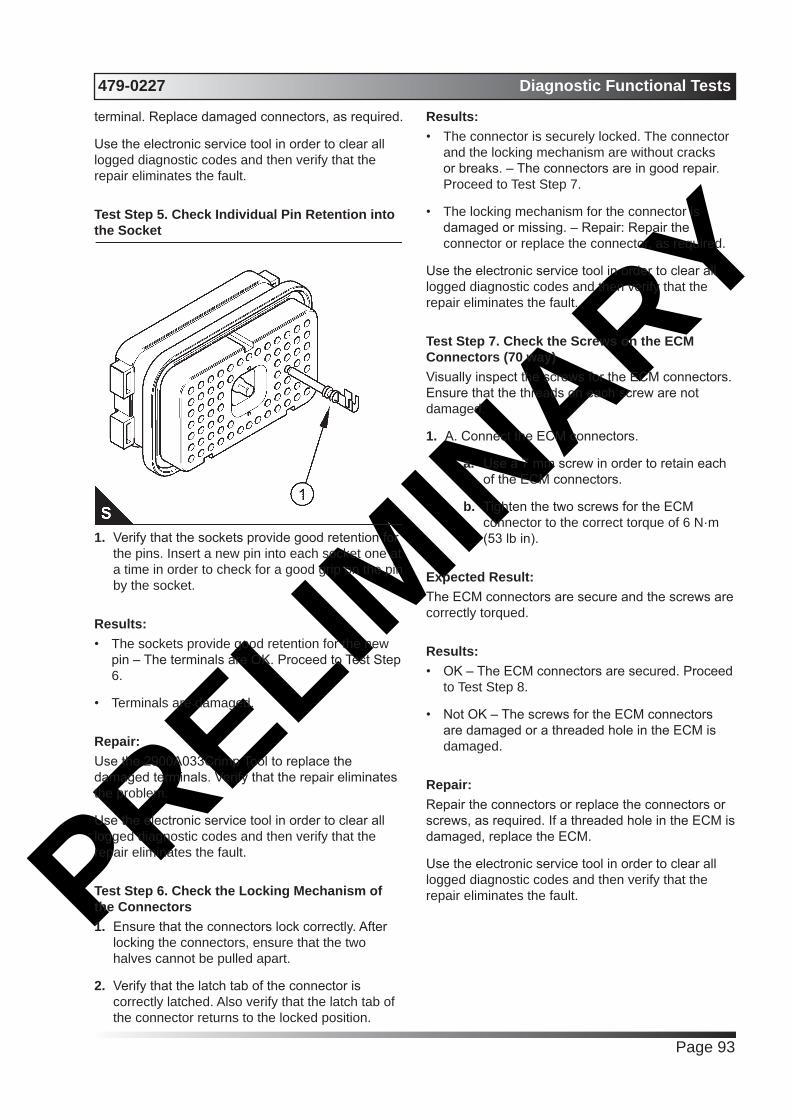
PRELIMIN
ARY479-0227 Diagnostic Functional Tests
Page 93
terminal. Replace damaged connectors, as required.
Use the electronic service tool in order to clear all logged diagnostic codes and then verify that the repair eliminates the fault.
Test Step 5. Check Individual Pin Retention into the Socket
1. Verify that the sockets provide good retention for the pins. Insert a new pin into each socket one at a time in order to check for a good grip on the pin by the socket.
Results:• The sockets provide good retention for the new
pin – The terminals are OK. Proceed to Test Step 6.
• Terminals are damaged.
Repair:Use the 2900A033Crimp Tool to replace the damaged terminals. Verify that the repair eliminates the problem.
Use the electronic service tool in order to clear all logged diagnostic codes and then verify that the repair eliminates the fault.
Test Step 6. Check the Locking Mechanism of the Connectors1. Ensure that the connectors lock correctly. After
locking the connectors, ensure that the two halves cannot be pulled apart.
2. Verify that the latch tab of the connector is correctly latched. Also verify that the latch tab of the connector returns to the locked position.
Results:• The connector is securely locked. The connector
and the locking mechanism are without cracks or breaks. – The connectors are in good repair. Proceed to Test Step 7.
• The locking mechanism for the connector is damaged or missing. – Repair: Repair the connector or replace the connector, as required.
Use the electronic service tool in order to clear all logged diagnostic codes and then verify that the repair eliminates the fault.
Test Step 7. Check the Screws on the ECM Connectors (70 way)Visually inspect the screws for the ECM connectors. Ensure that the threads on each screw are not damaged.
1. A. Connect the ECM connectors.
a. Use a 7 mm screw in order to retain each of the ECM connectors.
b. Tighten the two screws for the ECM connector to the correct torque of 6 N·m (53 lb in).
Expected Result:The ECM connectors are secure and the screws are correctly torqued.
Results:• OK – The ECM connectors are secured. Proceed
to Test Step 8.
• Not OK – The screws for the ECM connectors are damaged or a threaded hole in the ECM is damaged.
Repair: Repair the connectors or replace the connectors or screws, as required. If a threaded hole in the ECM is damaged, replace the ECM.
Use the electronic service tool in order to clear all logged diagnostic codes and then verify that the repair eliminates the fault.

PRELIMIN
ARYDiagnostic Functional Tests 479-0227
Page 94
Test Step 8. Perform the “Wiggle Test” on the Electronic Service Tool1. Select the “Wiggle Test” from the diagnostic tests
on the electronic service tool.
2. Choose the appropriate group of parameters to monitor.
3. Press the “Start” button. Wiggle the wiring harness in order to reproduce intermittent faults.
If an intermittent fault exists, the status will be highlighted and an audible beep will be heard.
Results:• No intermittent faults were indicated during the “Wiggle Test” – The harness and connectors appear to be OK. If you were sent from another procedure, return to the procedure and continue testing. If this test confirms that the fault has been eliminated, return the engine to service.
• At least one intermittent fault was indicated. –
Repair: Repair the harness or the connector.
Use the electronic service tool in order to clear all logged diagnostic codes and then verify that the repair eliminates the fault.
Engine Pressure Sensor Open or Short Circuit - TestSystem Operation Description:This procedure covers the following codes:
Diagnostic Trouble Codes for the Engine Pressure SensorsJ1939 Code
Description Notes
100-3 Engine Oil Pressure : Voltage Above Normal
The Electronic Control Module (ECM) detects the following conditions:The signal voltage from the engine oil pressure sensor is greater than 4.8 VDC for more than 8
seconds.If equipped, the warning lamp will come on. The ECM will log the diagnostic code. The ECM will set data for engine oil pressure to the default value. The default engine oil pressure is 600 kPa (87 psi).
The electronic service tool will display “Voltage Above Normal” on the status screens.
100-4 Engine Oil Pressure : Voltage Below Normal
The ECM detects the following conditions:The signal voltage from the engine oil pressure sensor is less than 0.2 VDC for more than 8
seconds.The ECM has been powered for at least 2 seconds.
The engine is running or the barometric pressure is greater than 55 kPa (8 psi).If equipped, the warning lamp will come on. The ECM will log the diagnostic code. The ECM will set data for the engine oil pressure to the default value. The default engine oil pressure is 600 kPa (87
psi). The electronic service tool will display “Voltage Below Normal” on the status screens.
108-3 Barometric Pressure : Voltage Above Normal
The ECM detects the following conditions:The signal voltage for the barometric pressure sensor is greater than 4.8 VDC for at least 8
seconds.If equipped, the warning lamp will come on. The ECM will log the diagnostic code.

PRELIMIN
ARY479-0227 Diagnostic Functional Tests
Page 95
108-4 Barometric Pressure: Voltage Below Normal
The ECM detects the following conditions:The signal voltage for the barometric pressure sensor is less than 0.2 VDC for at least 8 seconds.
If equipped, the warning lamp will come on. The ECM will log the diagnostic code.
157-3 Engine Injector Metering Rail #1
Pressure : Voltage Above Normal
The ECM detects the following conditions:The signal voltage for the fuel rail pressure sensor is more than 4.7 VDC for 0.6 seconds.
If equipped, the warning lamp will come on. The ECM will log the diagnostic code. The electronic servicetool will display “70000 kPa” next to “Desired Fuel Rail Pressure” and “Actual Fuel Rail
Pressure” on the status screens.The engine will be derated.
157-4 Engine Injector Metering Rail #1
Pressure : Voltage Below Normal
The ECM detects the following conditions:The signal voltage for the fuel rail pressure sensor is less than 0.67 VDC for 0.6 seconds.
If equipped, the warning lamp will come on. The ECM will log the diagnostic code.The electronic service tool will display “70000 kPa” next to “Desired Fuel Rail Pressure” and “Actual
Fuel Rail Pressure” on the status screens.The engine will be derated.
The following conditions must exist before any of the above codes will become active:
• There are no active 3509 codes.
• There are no active 168 codes.
The following background information is related to this procedure:
The 5 VDC sensor supply provides power to all 5 VDC sensors. The ECM supplies 5.0 ± 0.2 VDC to terminal “3” of the fuel rail pressure sensor connector and to terminal “1” of all other pressure sensor connectors. The sensor common from the ECM connector goes to terminal “1” of the connector for the fuel rail pressure sensor and to terminal “2” of all other pressure sensor connectors. The sensor supply is output short circuit protected. A short circuit to the battery will not damage the circuit inside the ECM.
Pull-up VoltageThe ECM continuously outputs a pull-up voltage on the circuit for the sensor signal wire. The ECM uses this pull-up voltage in order to detect an open in the signal circuit. When the ECM detects the presence of a voltage that is above a threshold on the signal circuit, the ECM will generate an open circuit diagnostic code (XXXX-3) for the sensor.
If the sensor is disconnected at the sensor connector, the presence of pull-up voltage at the sensor connector indicates that the wires from the sensor connector to the ECM are not open or shorted to ground. If the sensor is disconnected at the sensor connector, the absence of pull-up voltage at the sensor connector indicates an open in the signal wire or a short to ground. If the sensor is disconnected at the sensor connector and the voltage at the sensor connector is different from pull-up voltage, the signal wire is shorted to another wire in the harness.
Fuel rail pressure sensor
(1) Ground
(2) Signal
(3) 5 VDC Supply

PRELIMIN
ARYDiagnostic Functional Tests 479-0227
Page 96
Engine pressure sensor
(1) 5 VDC Supply
(2) Ground
(3) Signal
Note: The terminals on the fuel rail pressure sensor are wired differently from all other pressure sensors.
The pressure sensors are active sensors. The pressure sensors have three terminals. Active sensors require supply voltage from the ECM. The P2/J2 ECM connector supplies +5 VDC to terminal “3” of the fuel rail pressure sensor and to terminal “1” of all other pressure sensors. The common line is connected to connector “1” of the fuel rail pressure sensor and to connector “2” of all other pressure sensors. The signal voltage from terminal “2” of the fuel rail pressure sensor and from terminal “3” of all other pressure sensors is supplied to the appropriate terminal at the P2/J2 ECM connector.
Test Step 1. Inspect Electrical Connectors And Wiring1. Thoroughly inspect the terminal connections on
the P2/J2 ECM connectors.
2. Thoroughly inspect the connectors for the engine pressure sensors
3. Thoroughly inspect the 31-pin connector and the 40-pin connector.
4. Refer to Troubleshooting, “Electrical Connectors - Inspect”.
5. Perform a 45 N (10 lb) pull test on each of the wires in the ECM connector and the sensor connectors that are associated with the active diagnostic code.
6. Check the screw for the ECM connector for the correct torque of 6 N·m (53 lb in).
7. Check the harness for abrasions and for pinch points from the sensors back to the ECM.
8. Use the electronic service tool to perform a “Wiggle Test” . The “Wiggle Test” will identify intermittent connections.
Expected Result:All connectors, pins, and sockets are correctly connected. The harness should be free of corrosion, abrasions, and pinch points.
Results:
• OK Proceed to Test Step 2.
• Not OK
Repair: Repair the connectors or the harness and/or replace the connectors or the harness. Ensure that all of the seals are correctly in place and ensure that the connectors are correctly connected.
Use the electronic service tool in order to clear all logged diagnostic codes and then verify that the repair eliminates the fault.
Test Step 2. Check For Active Diagnostic Codes1. Turn the keyswitch to the ON position. Wait at
least 10 seconds for activation of the diagnostic codes.
2. Verify if any of the diagnostic codes that are listed.
Results:• An XXXX-3 or an XXXX-4 diagnostic code is
active for one or more of the pressure sensors. Proceed to Test Step 3.
• None of the preceding diagnostic codes are active.
Repair: If the codes in the table are logged, an intermittent condition may be causing the logged codes. Refer to Troubleshooting, “Electrical Connectors - Inspect”. Perform a “Wiggle Test” by using the electronic service tool in order to identify intermittent connections.
Test Step 3. Check the Supply Voltage at the Sensor Connector1. Turn the keyswitch to the OFF position.
2. Disconnect the connector for the suspect sensor.
3. Turn the keyswitch to the ON position. Do not start the engine.
4. Measure the voltage between the 5 VDC supply terminal and the ground terminal on the harness connector for the suspect sensor. The voltage measurement should be 5.0 ± 0.2 VDC.
5. Turn the keyswitch to the OFF position.
6. Reconnect the sensor.
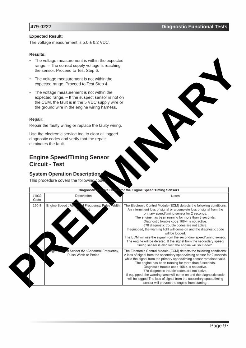
PRELIMIN
ARY479-0227 Diagnostic Functional Tests
Page 97
Expected Result:The voltage measurement is 5.0 ± 0.2 VDC.
Results:• The voltage measurement is within the expected
range. – The correct supply voltage is reaching the sensor. Proceed to Test Step 6.
• The voltage measurement is not within the expected range. Proceed to Test Step 4.
• The voltage measurement is not within the expected range. – If the suspect sensor is not on the CEM, the fault is in the 5 VDC supply wire or the ground wire in the engine wiring harness.
Repair:Repair the faulty wiring or replace the faulty wiring.
Use the electronic service tool to clear all logged diagnostic codes and verify that the repair eliminates the fault.
Engine Speed/Timing Sensor Circuit - TestSystem Operation Description:This procedure covers the following codes:
Diagnostic Trouble Codes for the Engine Speed/Timing SensorsJ1939 Code
Description Notes
190-8 Engine Speed : Abnormal Frequency, Pulse Width, or Period
The Electronic Control Module (ECM) detects the following conditions:An intermittent loss of signal or a complete loss of signal from the
primary speed/timing sensor for 2 seconds.The engine has been running for more than 3 seconds.
Diagnostic trouble code 168-4 is not active.678 diagnostic trouble codes are not active.
If equipped, the warning light will come on and the diagnostic code will be logged.
The ECM will use the signal from the secondary speed/timing sensor. The engine will be derated. If the signal from the secondary speed/
timing sensor is also lost, the engine will shut down.
723-8 Engine Speed Sensor #2 : Abnormal Frequency, Pulse Width or Period
The Electronic Control Module (ECM) detects the following conditions:A loss of signal from the secondary speed/timing sensor for 2 seconds while the signal from the primary speed/timing sensor remained valid.
The engine has been running for more than 3 seconds.Diagnostic trouble code 168-4 is not active.678 diagnostic trouble codes are not active.
If equipped, the warning lamp will come on and the diagnostic code will be logged.The loss of signal from the secondary speed/timing
sensor will prevent the engine from starting.
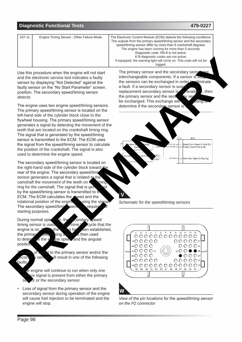
PRELIMIN
ARYDiagnostic Functional Tests 479-0227
Page 98
637-11 Engine Timing Sensor : Other Failure Mode The Electronic Control Module (ECM) detects the following conditions:The outputs from the primary speed/timing sensor and the secondary
speed/timing sensor differ by more than 8 crankshaft degrees.The engine has been running for more than 5 seconds.
Diagnostic code 190-8 is not active.678 diagnostic codes are not active.
If equipped, the warning light will come on. This code will not be logged.
Use this procedure when the engine will not start and the electronic service tool indicates a faulty sensor by displaying “Not Detected” against the faulty sensor on the “No Start Parameter” screen. position. The secondary speed/timing sensor detects
The engine uses two engine speed/timing sensors. The primary speed/timing sensor is located on the left-hand side of the cylinder block close to the flywheel housing. The primary speed/timing sensor generates a signal by detecting the movement of the teeth that are located on the crankshaft timing ring. The signal that is generated by the speed/timing sensor is transmitted to the ECM. The ECM uses the signal from the speed/timing sensor to calculate the position of the crankshaft. The signal is also used to determine the engine speed.
The secondary speed/timing sensor is located on the right-hand side of the cylinder block toward the rear of the engine. The secondary speed/timing sensor generates a signal that is related to the camshaft the movement of the teeth on the timing ring for the camshaft. The signal that is generated by the speed/timing sensor is transmitted to the ECM. The ECM calculates the speed and the rotational position of the engine by using the signal. The secondary speed/timing sensor is required for starting purposes.
During normal operation, the secondary speed/timing sensor is used to determine the cycle that the engine is on. When the timing has been established, the primary speed/timing sensor is then used to determine the engine speed and the angular position.
The loss of signal to the primary sensor and/or the secondary sensor will result in one of the following faults:
• The engine will continue to run when only one sensor signal is present from either the primary sensor or the secondary sensor.
• Loss of signal from the primary sensor and the secondary sensor during operation of the engine will cause fuel injection to be terminated and the engine will stop.
The primary sensor and the secondary sensor are interchangeable components. If a sensor is suspect, the sensors can be exchanged in order to eliminate a fault. If a secondary sensor is suspect and a replacement secondary sensor is not available, then the primary sensor and the secondary sensor can be exchanged. This exchange will allow testing to determine if the secondary sensor is faulty.
Schematic for the speed/timing sensors
View of the pin locations for the speed/timing sensor on the P2 connector
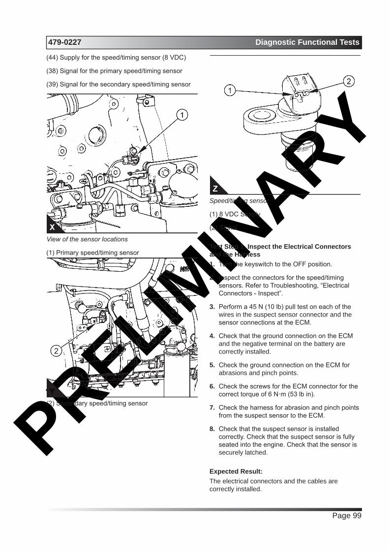
PRELIMIN
ARY479-0227 Diagnostic Functional Tests
Page 99
(44) Supply for the speed/timing sensor (8 VDC)
(38) Signal for the primary speed/timing sensor
(39) Signal for the secondary speed/timing sensor
View of the sensor locations
(1) Primary speed/timing sensor
(2) Secondary speed/timing sensor
Speed/timing sensor
(1) 8 VDC Supply
(2) Signal
Test Step 1. Inspect the Electrical Connectors and the Harness1. Turn the keyswitch to the OFF position.
2. Inspect the connectors for the speed/timing sensors. Refer to Troubleshooting, “Electrical Connectors - Inspect”.
3. Perform a 45 N (10 lb) pull test on each of the wires in the suspect sensor connector and the sensor connections at the ECM.
4. Check that the ground connection on the ECM and the negative terminal on the battery are correctly installed.
5. Check the ground connection on the ECM for abrasions and pinch points.
6. Check the screws for the ECM connector for the correct torque of 6 N·m (53 lb in).
7. Check the harness for abrasion and pinch points from the suspect sensor to the ECM.
8. Check that the suspect sensor is installed correctly. Check that the suspect sensor is fully seated into the engine. Check that the sensor is securely latched.
Expected Result:The electrical connectors and the cables are correctly installed.

PRELIMIN
ARYDiagnostic Functional Tests 479-0227
Page 100
Results:• The harness is OK. Proceed to Test Step 2.
• Not OK
Repair: Repair the faulty connectors or the harness and/or replace the faulty connectors or the harness. Ensure that all of the seals are correctly in place and ensure that the connectors are correctly coupled.
If the primary speed/timing sensor must be replaced or the sensor must be reinstalled, refer to Disassembly and Assembly, “Crankshaft Position Sensor - Remove and Install”. If the secondary speed/timing sensor must be replaced or the sensor must be reinstalled, refer to Disassembly and Assembly, “Camshaft Position Sensor - Remove and Install”.
Use the electronic service tool in order to clear all logged diagnostic codes and then verify that the repair has eliminated the fault.
Test Step 2. Check for Active Diagnostic Codes and Recently Logged Diagnostic Codes1. Turn the keyswitch to the OFF position.
2. Connect the electronic service tool to the diagnostic connector.
3. Turn the keyswitch to the ON position. If the engine will start, then run the engine.
4. Use the electronic service tool in order to monitor active diagnostic codes or recently logged diagnostic codes.
Results:• Diagnostic code 190-8 is active or recently
logged. Proceed to Test Step 5.
• Diagnostic code 723-8 is active or recently logged. Proceed to Test Step 5.
• Diagnostic code 637-11 is active or recently logged. Proceed to Test Step 3.
• No active diagnostic codes or recently logged diagnostic codes are displayed.
Test Step 3. Inspect the Sensors1. Ensure that the speed/timing sensors are
correctly seated in the cylinder block and that the retaining bolts are tightened to a torque of 22 N·m (16 lb ft). Ensure that the speed/timing sensors are not damaged.
Replace any damaged sensors. Refer to Disassembly and Assembly, “Crankshaft Position Sensor - Remove and Install” or refer to Disassembly and Assembly, “Camshaft Position Sensor - Remove and Install”.
2. Use the electronic service tool to check if the 637- 11 diagnostic code is still active.
Results:• A 637-11 diagnostic code is still active at this
time. Proceed to Test Step 4.
• A 637-11 diagnostic code is not active at this time. – Use the electronic service tool to clear all logged diagnostic codes and verify that the repair eliminates the fault.
Test Step 4. Check the Crankshaft Timing Ring and the Timing Ring on the Camshaft1. Remove the primary speed/timing sensor and
the secondary speed/timing sensor. Refer to Disassembly and Assembly, “Crankshaft Position Sensor - Remove and Install” or refer to Disassembly and Assembly, “Camshaft Position Sensor - Remove and Install”.
2. Use a flashlight in order to check the timing ring on the camshaft through the camshaft timing hole for damage.
3. Use a flashlight in order to check the crankshaft timing ring for damaged teeth or missing teeth. Ensure that the crankshaft timing ring has not been displaced from the crankshaft.
Results:• Found fault with the crankshaft timing ring or the timing ring on the camshaft
Repair: If necessary, replace the camshaft. Refer to Disassembly and Assembly, “Camshaft - Remove” and refer to Disassembly and Assembly, “Camshaft - Install”.
If necessary, replace the crankshaft timing ring. Refer to Disassembly and Assembly, “Crankshaft Timing Ring - Remove and Install” .
Use the electronic service tool in order to clear all logged diagnostic codes and then verify that the repair has eliminated the fault.
• No faults found Proceed to Test Step 3.
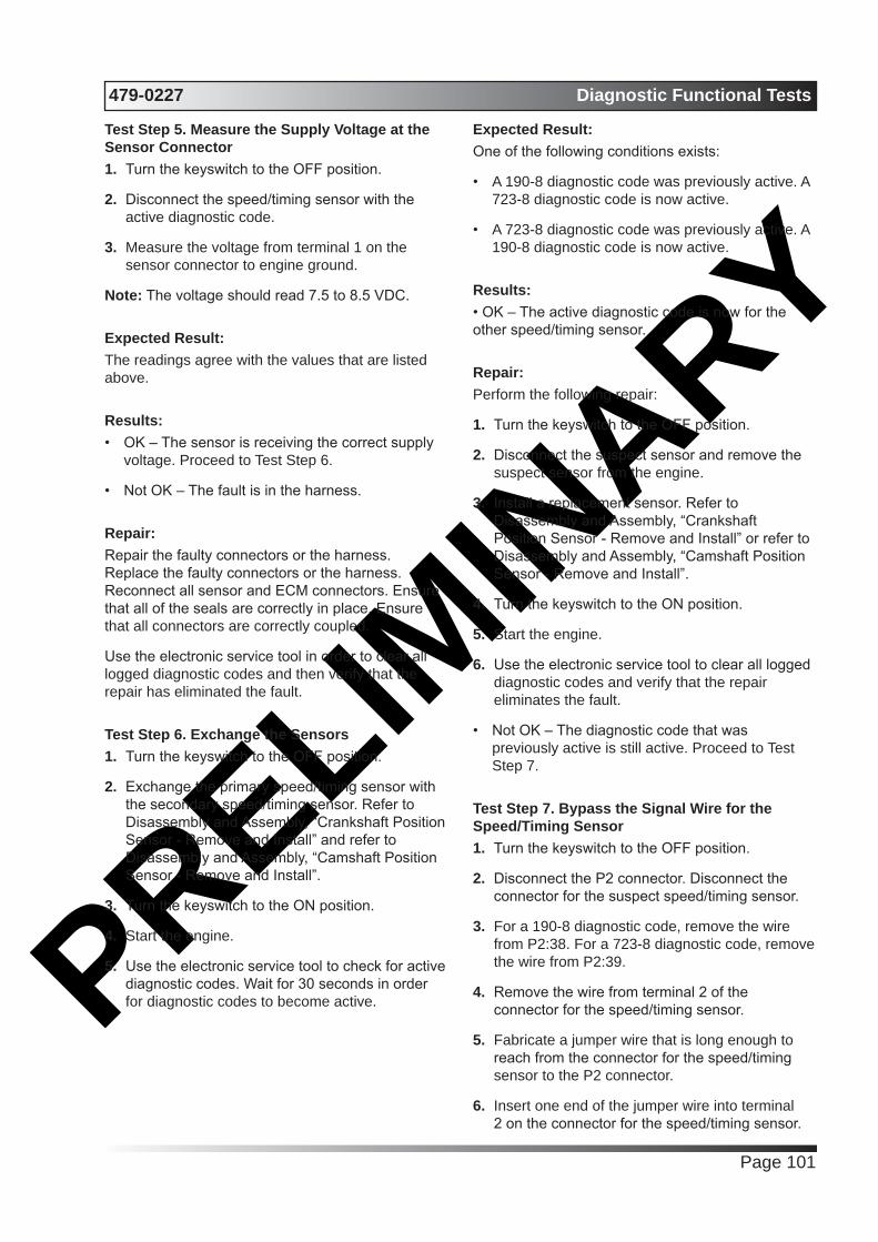
PRELIMIN
ARY479-0227 Diagnostic Functional Tests
Page 101
Test Step 5. Measure the Supply Voltage at the Sensor Connector1. Turn the keyswitch to the OFF position.
2. Disconnect the speed/timing sensor with the active diagnostic code.
3. Measure the voltage from terminal 1 on the sensor connector to engine ground.
Note: The voltage should read 7.5 to 8.5 VDC.
Expected Result:The readings agree with the values that are listed above.
Results:• OK – The sensor is receiving the correct supply
voltage. Proceed to Test Step 6.
• Not OK – The fault is in the harness.
Repair: Repair the faulty connectors or the harness. Replace the faulty connectors or the harness. Reconnect all sensor and ECM connectors. Ensure that all of the seals are correctly in place. Ensure that all connectors are correctly coupled.
Use the electronic service tool in order to clear all logged diagnostic codes and then verify that the repair has eliminated the fault.
Test Step 6. Exchange the Sensors1. Turn the keyswitch to the OFF position.
2. Exchange the primary speed/timing sensor with the secondary speed/timing sensor. Refer to Disassembly and Assembly, “Crankshaft Position Sensor - Remove and Install” and refer to Disassembly and Assembly, “Camshaft Position Sensor - Remove and Install”.
3. Turn the keyswitch to the ON position.
4. Start the engine.
5. Use the electronic service tool to check for active diagnostic codes. Wait for 30 seconds in order for diagnostic codes to become active.
Expected Result:One of the following conditions exists:
• A 190-8 diagnostic code was previously active. A 723-8 diagnostic code is now active.
• A 723-8 diagnostic code was previously active. A 190-8 diagnostic code is now active.
Results:• OK – The active diagnostic code is now for the other speed/timing sensor.
Repair: Perform the following repair:
1. Turn the keyswitch to the OFF position.
2. Disconnect the suspect sensor and remove the suspect sensor from the engine.
3. Install a replacement sensor. Refer to Disassembly and Assembly, “Crankshaft Position Sensor - Remove and Install” or refer to Disassembly and Assembly, “Camshaft Position Sensor - Remove and Install”.
4. Turn the keyswitch to the ON position.
5. Start the engine.
6. Use the electronic service tool to clear all logged diagnostic codes and verify that the repair eliminates the fault.
• Not OK – The diagnostic code that was previously active is still active. Proceed to Test Step 7.
Test Step 7. Bypass the Signal Wire for the Speed/Timing Sensor1. Turn the keyswitch to the OFF position.
2. Disconnect the P2 connector. Disconnect the connector for the suspect speed/timing sensor.
3. For a 190-8 diagnostic code, remove the wire from P2:38. For a 723-8 diagnostic code, remove the wire from P2:39.
4. Remove the wire from terminal 2 of the connector for the speed/timing sensor.
5. Fabricate a jumper wire that is long enough to reach from the connector for the speed/timing sensor to the P2 connector.
6. Insert one end of the jumper wire into terminal 2 on the connector for the speed/timing sensor.

PRELIMIN
ARYDiagnostic Functional Tests 479-0227
Page 102
Insert the other end of the jumper wire into the terminal for the signal of the speed/timing sensor on the P2 connector.
7. Reconnect the P2 connector and the connector for the speed/timing sensor.
8. Turn the keyswitch to the ON position.
9. Start the engine. If the engine will start, then run the engine.
10. Use the electronic service tool to check for active diagnostic codes. Wait for 30 seconds in order for diagnostic codes to become active.
Expected Result:There are no active diagnostic codes.
Results:• OK – The fault is in the harness.
Repair:Repair the faulty connectors or replace the faulty connectors. Repair the faulty harness or replace the faulty harness. Reconnect all sensor and ECM connectors. Ensure that all of the seals are correctly in place. Ensure that all connectors are correctly coupled.
Use the electronic service tool in order to clear all logged diagnostic codes and then verify that the repair eliminates the fault.
• Not OK – The XXX-8 diagnostic code for the speed/timing sensor is still active. Proceed to Test Step 8.
Test Step 8. Check if the Replacement of the ECM Eliminates the Fault1. Make sure that the latest flash file for the
application is installed in the ECM. Refer to Troubleshooting, “Flash Programming”.
2. Contact Perkins Global Technical Support.
Note: This consultation can greatly reduce the repair time.
3. If Perkins Global Technical Support recommends the use of a test ECM, install a test ECM. Refer to Troubleshooting, “Replacing the ECM”.
4. Use the electronic service tool to recheck the system for active diagnostic codes.
Results:• The fault is eliminated.
Repair:Perform the following procedure:
1. Reconnect the suspect ECM.
2. If the fault returns with the suspect ECM, replace the ECM.
3. Use the electronic service tool in order to clear all logged diagnostic codes and then verify that the repair eliminates the fault.
• The fault was not resolved with a test ECM. –
Repair: Repeat this diagnostic process. If the fault persists, the fault may be a damaged timing ring. Check the timing ring and/or replace the timing ring. Refer to Disassembly and Assembly, “Crankshaft Timing Ring - Remove and Install”.
Use the electronic service tool in order to clear all logged diagnostic codes and then verify that the repair eliminates the fault.
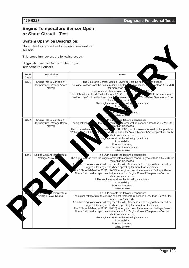
PRELIMIN
ARY479-0227 Diagnostic Functional Tests
Page 103
Engine Temperature Sensor Open or Short Circuit - TestSystem Operation Description:Note: Use this procedure for passive temperature sensors.
This procedure covers the following codes:
Diagnostic Trouble Codes for the Engine Temperature Sensors
J1939 Code
Description Notes
105-3 Engine Intake Manifold #1 Temperature : Voltage Above
Normal
The Electronic Control Module (ECM) detects the following conditions:The signal voltage from the intake manifold air temperature sensor is greater than 4.95 VDC
for more than 8 seconds.Engine coolant temperature is above -10 °C (15.0 °F).
The ECM will use the default value of 70 °C (158 °F) for the intake manifold air temperature. “Voltage High” will be displayed next to the status for “Intake Manifold Air Temperature” on
the electronic service tool.The engine may show the following symptoms:
Poor stabilityPoor cold running
Poor acceleration under loadWhite smoke
105-4 Engine Intake Manifold #1 Temperature : Voltage Below
Normal
The ECM detects the following conditions:The signal voltage from the intake manifold air temperature sensor is less than 0.2 VDC for
more than 8 seconds.The ECM will use the default value of 70 °C (158°F) for the intake manifold air temperature. “VoltageLow” will be displayed next to the status for “Intake Manifold Air Temperature” on the
electronic service tool.The engine may show the following symptoms:
Poor stabilityPoor cold running
Poor acceleration under loadWhite smoke
110-3 Engine Coolant Temperature: Voltage Above Normal
The ECM detects the following conditions:The signal voltage from the engine coolant temperature sensor is greater than 4.95 VDC for
more than 8 seconds.An active diagnostic code will be generated after 8 seconds. The diagnostic code will be
logged if the engine has been operating for more than 7 minutes.The ECM will default to 90 °C (194 °F) for engine coolant temperature. “Voltage Above Normal” will be displayed next to the status for “Engine Coolant Temperature” on the
electronic service tool.# The engine may show the following symptoms:
Poor stabilityPoor cold running
White smoke
110-4 Engine Coolant Temperature: Voltage Below Normal
The ECM detects the following conditions:The signal voltage from the engine coolant temperature sensor is less than 0.2 VDC for
more than 8 secondsAn active diagnostic code will be generated after 8 seconds. The diagnostic code will be
logged if the engine has been operating for more than 7 minutes.The ECM will default to 90 °C (194 °F) for engine coolant temperature. “Voltage Below Normal” will be displayed next to the status for “Engine Coolant Temperature” on the
electronic service tool.The engine may show the following symptoms:
Poor stabilityPoor cold running
White smoke

PRELIMIN
ARYDiagnostic Functional Tests 479-0227
Page 104
174-3 Engine Fuel Temperature 1 : Voltage Above Normal
The ECM detects the following conditions:The signal voltage from the air inlet temperature sensor is less than 0.2 VDC for at least 8
seconds.The ECM will default to 40° C (104° F) for fuel temperature. “Voltage Above Normal” will be
displayed next to the status for “Engine Fuel Temperature” on the electronic service tool.
174-4 Engine Fuel Temperature 1 : Voltage Below Normal
The ECM detects the following conditions:The signal voltage from the fuel temperature sensor is less than 0.2 VDC for more than 8
seconds.The ECM will default to 40° C (104° F) for fuel temperature. “Voltage Below Normal” will be
displayed next to the status for “Engine Fuel Temperature” on the electronic service tool.
Note: The following conditions must exist before any of the above codes will become active:
• The ECM has been powered for at least 2 seconds.
• Diagnostic code 168-4 is not active.
The ECM will log the diagnostic code. If equipped, the warning light will come on.
This procedure covers open circuit diagnostic codes and short circuit diagnostic codes that are associated with the following sensors:
• Coolant temperature sensor
• Intake manifold air temperature sensor
• NRS temperature sensor
• Fuel temperature sensor
• Air inlet temperature sensor
The following background information is related to this procedure:
The troubleshooting procedures for the diagnostic codes of each temperature sensor are identical. The temperature sensors have two terminals. The signal line is connected to each sensor connector terminal 1. Terminal 2 is the return line. The signal voltage from terminal 1 of each sensor is supplied to the appropriate terminal in the P2/J2 connector or the P1/ J1 connector.
Pull-up VoltageThe ECM continuously outputs a pull-up voltage on the circuit for the sensor signal wire. The ECM uses this pull-up voltage in order to detect an open in the signal circuit. When the ECM detects the presence of a voltage that is above a threshold on the signal circuit, the ECM will generate an open circuit diagnostic code (XXX-3) for the sensor.
If the sensor is disconnected at the sensor connector, the presence of pull-up voltage at the sensor connector indicates that the wires from the sensor connector to the ECM are not open or
shorted to ground. If the sensor is disconnected at the sensor connector, the absence of pull-up voltage at the sensor connector indicates an open in the signal wire or a short to ground. If the sensor is disconnected at the sensor connector and the voltage at the sensor connector is different from pull-up voltage, the signal wire is shorted to another wire in the harness.
View of the P2 pin locations for the cations for the temperature sensors
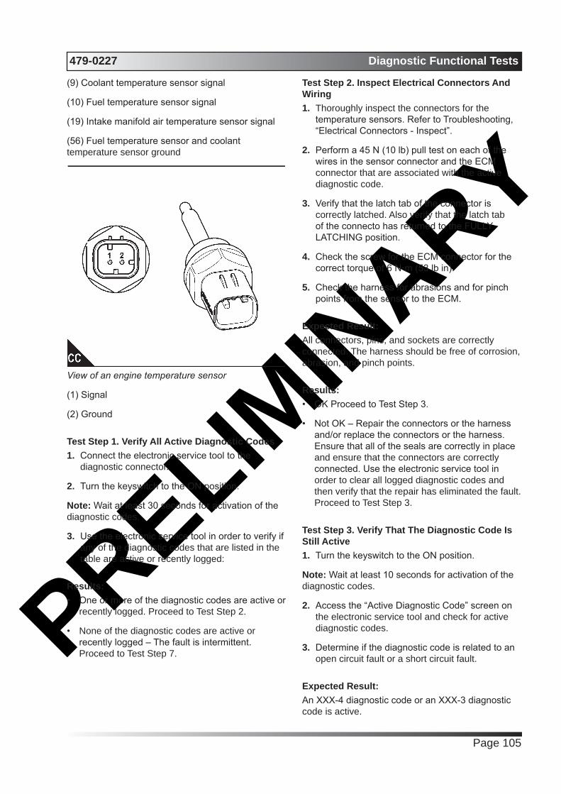
PRELIMIN
ARY479-0227 Diagnostic Functional Tests
Page 105
(9) Coolant temperature sensor signal
(10) Fuel temperature sensor signal
(19) Intake manifold air temperature sensor signal
(56) Fuel temperature sensor and coolant temperature sensor ground
View of an engine temperature sensor
(1) Signal
(2) Ground
Test Step 1. Verify All Active Diagnostic Codes1. Connect the electronic service tool to the
diagnostic connector.
2. Turn the keyswitch to the ON position.
Note: Wait at least 30 seconds for activation of the diagnostic codes.
3. Use the electronic service tool in order to verify if any of the diagnostic codes that are listed in the table are active or recently logged:
Results:• One or more of the diagnostic codes are active or
recently logged. Proceed to Test Step 2.
• None of the diagnostic codes are active or recently logged – The fault is intermittent. Proceed to Test Step 7.
Test Step 2. Inspect Electrical Connectors And Wiring1. Thoroughly inspect the connectors for the
temperature sensors. Refer to Troubleshooting, “Electrical Connectors - Inspect”.
2. Perform a 45 N (10 lb) pull test on each of the wires in the sensor connector and the ECM connector that are associated with the active diagnostic code.
3. Verify that the latch tab of the connector is correctly latched. Also verify that the latch tab of the connecto has returned to the FULLY LATCHING position.
4. Check the screw for the ECM connector for the correct torque of 6 N·m (53 lb in).
5. Check the harness for abrasions and for pinch points from the sensor to the ECM.
Expected Result:All connectors, pins, and sockets are correctly connected. The harness should be free of corrosion, abrasion, and pinch points.
Results:• OK Proceed to Test Step 3.
• Not OK – Repair the connectors or the harness and/or replace the connectors or the harness. Ensure that all of the seals are correctly in place and ensure that the connectors are correctly connected. Use the electronic service tool in order to clear all logged diagnostic codes and then verify that the repair has eliminated the fault. Proceed to Test Step 3.
Test Step 3. Verify That The Diagnostic Code Is Still Active1. Turn the keyswitch to the ON position.
Note: Wait at least 10 seconds for activation of the diagnostic codes.
2. Access the “Active Diagnostic Code” screen on the electronic service tool and check for active diagnostic codes.
3. Determine if the diagnostic code is related to an open circuit fault or a short circuit fault.
Expected Result:An XXX-4 diagnostic code or an XXX-3 diagnostic code is active.

PRELIMIN
ARYDiagnostic Functional Tests 479-0227
Page 106
Results:• SHORT Circuit – A XXX-4 diagnostic code is
active at this time. Proceed to Test Step 4.
• OPEN Circuit – A XXX-3 diagnostic code is active at this time. Proceed to Test Step 5.
• An XXX-3 diagnostic code is not active. An XXX-4 diagnostic code is not active – An intermittent fault may exist. Proceed to Test Step 7.
Test Step 4. Disconnect The Sensor In Order To Create An Open Circuit1. Turn the keyswitch to the OFF position.
2. Disconnect the sensor connector of the sensor with the XXX-4 diagnostic code.
3. Turn the keyswitch to the ON position.
Note: Wait at least 10 seconds for activation of the diagnostic codes.
4. Access the “Active Diagnostic Code” screen of the electronic service tool. Check for an active XXX-3 diagnostic code.
Results:• An XXX-4 diagnostic code was active before
disconnecting the sensor. An XXX-3 diagnostic code became active after disconnecting the sensor.
Repair: Refer to Troubleshooting, “Electrical Connectors - Inspect”.
Inspect the seals of the connectors for damage.
Connect the sensor and verify that the XXX-4 diagnostic code returns. If the diagnostic code returns, the sensor is faulty.
Replace the sensor.
Use the electronic service tool in order to clear all logged diagnostic codes.
• An XXXX-4 diagnostic code was active before disconnecting the sensor. The diagnostic code is still active after disconnecting the sensor. – There is a short circuit between the sensor harness connector and the ECM. Leave the sensor disconnected. Proceed to Test Step 6.
Test Step 5. Create a Short Circuit Between the Signal and the Common
Terminals at the Sensor Harness Connector1. Disconnect the suspect sensor connector.
2. Turn the keyswitch to the ON position.
Note: Wait at least 10 seconds for the activation of any diagnostic fault codes.
3. Fabricate a jumper wire 150 mm (6 inch) long. Crimp a terminal to both ends of the wire.
4. Monitor the “Active Diagnostic Code” screen on the electronic service tool before installing the jumper wire and after installing the jumper wire.
5. Install the jumper on the engine harness connector for the suspect sensor. Install one end of the jumper at the sensor signal (terminal 1). Install the other end of the jumper at the common connection (terminal 2).
Note: Wait at least 10 seconds for activation of the Voltage Below Normal diagnostic code.
Results:• An XXX-4 diagnostic code is active when the
jumper is installed. An XXX-3 diagnostic code is active when the jumper is removed. – The engine harness and the ECM are OK.
Repair: Perform the following repair:
1. Temporarily connect the suspect sensor.
2. If the diagnostic code remains active, replace the sensor.
3. Use the electronic service tool in order to clear all logged diagnostic codes and then verify that the repair eliminates the fault.
4. Clear all logged diagnostic codes.
• The XXX-3 diagnostic code remains active with the jumper in place. – The most probable location for the open circuit is in the sensor common or the sensor signal wire in the engine harness between the ECM and the sensor. Remove the jumper. Proceed to Test Step 6.

PRELIMIN
ARY479-0227 Diagnostic Functional Tests
Page 107
Test Step 6. Bypass the Harness Wiring between the ECM and the Sensor Connector1. Turn the keyswitch to the OFF position.
2. If the suspect sensor is the air inlet temperature sensor, disconnect the P1 connector and the connector on the air inlet temperature sensor. For all other sensors, disconnect the P2 connector and the connector on the suspect sensor.
3. Thoroughly inspect the ECM connectors. Refer to Troubleshooting, “Electrical Connectors -Inspect”.
4. Remove the signal wire for the suspect sensor from the P1 connector or the P2 connector.
5. Remove the signal wire (terminal 1) from the sensor connector on the engine harness.
6. Fabricate a jumper wire that is long enough to reach from the ECM to the sensor connector with sockets on both ends.
7. Insert one end of the jumper into the ECM connector. Insert the other end of the jumper into the sensor connector of the engine harness.
8. Remove the ground wire (terminal 2) from the sensor connector on the engine harness.
9. Remove the ground wire for the suspect sensor from the P1 connector or the P2 connector.
10. Fabricate a jumper wire that is long enough to reach from the ECM to the sensor connector with sockets on both ends.
11. Insert one end of the jumper into the ECM connector. Insert the other end of the jumper into the sensor connector of the engine harness.
12. Reconnect the connector for the ECM harness and the sensor connector.
13. Turn the keyswitch to the ON position.
14. Use the electronic service tool in order to monitor the “Active Diagnostic Code” screen for either the open circuit diagnostic code for the sensor or the short circuit diagnostic code for the sensor.
15. Remove the jumper and reconnect the wires that were previously removed.
16. Reconnect the P1 connector or the P2 connector and reconnect the connector for the suspect sensor.
Results:• The diagnostic code disappears when the jumper is installed. – There is a fault in the wiring harness.
Repair: Perform the following repair:
1. Repair the faulty harness or replace the faulty harness.
2. Use the electronic service tool in order to clear all logged diagnostic codes and then verify that the repair eliminates the fault.
• The diagnostic code is still present when the jumper is installed
Repair: Perform the following repair:
1. Make sure that the latest flash file for the application is installed in the ECM. Refer to Troubleshooting, “Flash Programming”.
2. Contact Perkins Global Technical Support.
Note: This consultation can greatly reduce the repair time.
3. If Perkins Global Technical Support recommend the use of a test ECM, install a test ECM. Refer to Troubleshooting, “Replacing the ECM”.
4. Use the electronic service tool to recheck the system for active diagnostic codes.
5. If the fault is eliminated with the test ECM, reconnect the suspect ECM.
6. If the fault returns with the suspect ECM, replace the ECM.
7. Use the electronic service tool in order to clear all logged diagnostic codes and then verify that the repair eliminates the fault.
Test Step 7. Perform the “Wiggle Test” on the Electronic Service Tool1. Select the “Wiggle Test” from the diagnostic tests
on the electronic service tool.
2. Choose the appropriate group of parameters to monitor.
3. Press the “Start” button. Wiggle the wiring harness in order to reproduce intermittent faults.
If an intermittent fault exists, the status will be highlighted and an audible beep will be heard.

PRELIMIN
ARYDiagnostic Functional Tests 479-0227
Page 108
Expected Result:
Results:• No intermittent faults were indicated during the
“Wiggle Test” . – The harness and connectors appear to be OK. If this test has not identified a fault, return the engine to service.
• At least one intermittent fault was indicated. –
Repair: Repair the harness or the connector.
Use the electronic service tool in order to clear all logged diagnostic codes and then verify that the repair eliminates the fault.
Fuel Pump Relay Circuit - Test (Customer Wiring)System Operation Description:Use this procedure to troubleshoot the relay for the Electric Fuel Lift Pump (EFLP). Use this procedure if there is a suspected electrical fault with the EFLP.
This procedure covers the following diagnostic codes
Diagnostic Trouble Codes for the Circuit for the EFLP RelayJ1939 Code
Description Notes
1075-5 Engine Electric Lift Pump for Engine Fuel supply: Current Below Normal
The Electronic Control Module (ECM) detects the following conditions:There are no active 168 diagnostic codes.
The ECM is not attempting to power the relay.The ECM has been powered for at least 2 seconds.
There is a low current condition in the fuel lift pump relay circuit for more than 2 seconds.
The warning light will come on. The diagnostic code will be logged.The ECM is unable to activate the relay for the fuel lift pump. The fuel lift
pump will not operate or the fuel lift pump will operate all the time. The engine will not operate.
1075-6 Engine Electric Lift Pump for Engine Fuel supply: Current Above Normal
The ECM detects the following conditions:There are no active 168 diagnostic codes.The ECM is attempting to power the relay.
The ECM has been powered for at least 2 seconds.There is a high current condition in the fuel lift pump relay circuit for more
than 2 seconds.The warning light will come on. The diagnostic code will be logged.
The ECM is unable to activate the relay for the fuel lift pump. The fuel lift pump will not operate or the fuel lift pump will operate all the time. The engine
will not operate.The ECM will continue to attempt to activate the relay. If the current is OK for
6 seconds, then the diagnostic code will be cleared.
The following background information is related to this procedure:
The EFLP is used in order to provide positive fuel pressure to the high-pressure fuel pump. When the keyswitch is turned to the ON position, the ECM will

PRELIMIN
ARY479-0227 Diagnostic Functional Tests
Page 109
activate the relay for the EFLP. If the engine is not running, the ECM will deactivate the relay for the EFLP after 2 minutes.
Schematic for the Electric Fuel Lift Pump (EFLP)
View of the pin location on the P1 connector for the EFLP.
(21) Relay for the EFLP
Test Step 1. Inspect Electrical Connectors and Wiring1. Check that the fuses are not blown.
2. Check the harness for abrasion and pinch points from the Electric Fuel Lift Pump (EFLP) back to the ECM. Check the harness for abrasion and pinch points from the EFLP back to the battery.
3. Inspect the terminals on the EFLP relay and then inspect the harness connector for the relay.
Refer to Troubleshooting, “Electrical Connectors - Inspect” for details.
4. Inspect the connector for the EFLP. Refer to Troubleshooting, “Electrical Connectors - Inspect” for details.
5. Perform a 45 N (10 lb) pull test on each of the wires in the ECM connector that are associated with the EFLP.
6. Check the screw for the ECM connector for the correct torque of 6 N·m (53 lb in).
Results:• All connectors, pins, and sockets are correctly
coupled and/or inserted. The harness is free of corrosion, abrasion, and pinch points. The fuses are not blown Proceed to Test Step 2.
• There is a fault with the harness and connectors
Repair: Repair the connectors or the harness and/or replace the connectors or the harness. Ensure that all of the seals are correctly in place and ensure that the connectors are correctly connected. Replace blown fuses.
1. Turn the keyswitch to the ON position. Do not start the engine. Check for active diagnostic codes.
2. Wait for at least 2 minutes for the EFLP to
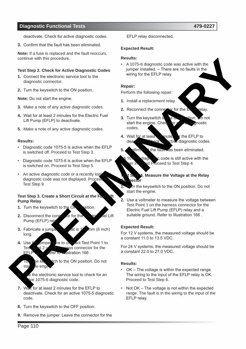
PRELIMIN
ARYDiagnostic Functional Tests 479-0227
Page 110
deactivate. Check for active diagnostic codes.
3. Confirm that the fault has been eliminated.
Note: If a fuse is replaced and the fault reoccurs, continue with this procedure.
Test Step 2. Check for Active Diagnostic Codes1. Connect the electronic service tool to the
diagnostic connector.
2. Turn the keyswitch to the ON position.
Note: Do not start the engine.
3. Make a note of any active diagnostic codes.
4. Wait for at least 2 minutes for the Electric Fuel Lift Pump (EFLP) to deactivate.
5. Make a note of any active diagnostic codes.
Results:• Diagnostic code 1075-5 is active when the EFLP
is switched off. Proceed to Test Step 3.
• Diagnostic code 1075-6 is active when the EFLP is switched on. Proceed to Test Step 5.
• An active diagnostic code or a recently logged diagnostic code was not displayed. Proceed to Test Step 9.
Test Step 3. Create a Short Circuit at the Fuel Lift Pump Relay1. Turn the keyswitch to the OFF position.
2. Disconnect the connector for the Electric Fuel Lift Pump (EFLP) relay.
3. Fabricate a jumper wire that is 150 mm (6 inch) long.
4. Use the jumper wire to connect Test Point 1 to Test point 2 on the harness connector for the EFLP relay. Refer to Illustration 166 .
5. Turn the keyswitch to the ON position. Do not start the engine.
6. Use the electronic service tool to check for an active 1075-6 diagnostic code.
7. Wait for at least 2 minutes for the EFLP to deactivate. Check for an active 1075-5 diagnostic code.
8. Turn the keyswitch to the OFF position.
9. Remove the jumper. Leave the connector for the
EFLP relay disconnected.
Expected Result:
Results:• A 1075-6 diagnostic code was active with the
jumper installed. – There are no faults in the wiring for the EFLP relay.
Repair: Perform the following repair:
1. Install a replacement relay.
2. Reconnect the connector for the EFLP relay.
3. Turn the keyswitch to the ON position. Do not start the engine. Check for active diagnostic codes.
4. Wait for at least 2 minutes for the EFLP to deactivate. Check for active diagnostic codes.
5. Confirm that the fault has been eliminated.
• A 1075-5 diagnostic code is still active with the jumper installed Proceed to Test Step 4.
Test Step 4. Measure the Voltage at the Relay Connector1. Turn the keyswitch to the ON position. Do not
start the engine.
2. Use a voltmeter to measure the voltage between Test Point 1 on the harness connector for the Electric Fuel Lift Pump (EFLP) relay and a suitable ground. Refer to Illustration 166 .
Expected Result:For 12 V systems, the measured voltage should be a constant 11.0 to 13.5 VDC.
For 24 V systems, the measured voltage should be a constant 22.0 to 27.0 VDC.
Results:• OK – The voltage is within the expected range.
The wiring to the input of the EFLP relay is OK. Proceed to Test Step 6.
• Not OK – The voltage is not within the expected range. The fault is in the wiring to the input of the EFLP relay.

PRELIMIN
ARY479-0227 Diagnostic Functional Tests
Page 111
Repair: Perform the following repair:
1. Repair the faulty wiring or replace the faulty wiring.
2. Turn the keyswitch to the ON position. Do not start the engine. Check for active diagnostic codes
3. Wait for at least 2 minutes for the EFLP to deactivate. Check for active diagnostic codes.
4. Confirm that the fault has been eliminated.
Test Step 5. Create an Open Circuit at the Relay1. Turn the keyswitch to the OFF position.
2. Disconnect the connector for the Electric Fuel Lift Pump (EFLP) relay.
3. Turn the keyswitch to the ON position. Do not start the engine.
4. Use the electronic service tool to check for an active 1075-6 diagnostic code.
5. Wait for at least 2 minutes for the EFLP to deactivate. Check for an active 1075-5 diagnostic code.
Results:• A 1075-6 diagnostic code is still active with the
EFLP relay disconnected. – The EFLP relay is OK. Proceed to Test Step 6.
• A 1075-5 diagnostic code became active with the EFLP relay disconnected. – The wiring for the EFLP relay is OK.
Repair: Perform the following repair:
1. Install a replacement relay.
2. Turn the keyswitch to the ON position. Do not start the engine. Check for active diagnostic codes.
3. Wait for at least 2 minutes for the EFLP to deactivate. Check for active diagnostic codes.
4. Confirm that the fault has been eliminated.
Test Step 6. Check the Wiring Between the Relay and the ECM for an Open Circuit1. Turn the keyswitch to the OFF position.
2. Disconnect the P1 connector.
3. Inspect the P1/J1 connector. Refer to Troubleshooting, “Electrical Connectors - Inspect”.
4. Disconnect the connector for the Electric Fuel Lift Pump (EFLP) relay.
5. Measure the resistance between P1:21 and Test Point 2 on the harness connector for the EFLP relay.
6. Reconnect the P1 connector. Reconnect the connector for the EFLP relay.
Expected Result:The resistance should be less than 10,000 Ohms.
Results:• OK – The resistance is less than 10,000 Ohms.
There may be a fault with the ECM. Proceed to Test Step 8.
• Not OK – The resistance is more than 10,000 Ohms. The fault is in the wiring between the ECM and the EFLP relay.
Repair: Perform the following repair:
1. Repair the faulty wiring or replace the faulty wiring.
2. Turn the keyswitch to the ON position. Do not start the engine. Check for active diagnostic codes.
3. Wait for at least 2 minutes for the EFLP to deactivate. Check for active diagnostic codes.
4. Confirm that the fault has been eliminated.
Test Step 7. Check the Wiring between the Relay and the ECM for a Short Circuit1. Turn the keyswitch to the OFF position.
2. Disconnect the P1 connector.
3. Inspect the P1/J1 connector. Refer to Troubleshooting, “Electrical Connectors - Inspect”.
4. Disconnect the connector for the Electric Fuel Lift

PRELIMIN
ARYDiagnostic Functional Tests 479-0227
Page 112
Pump (EFLP) relay.
5. Measure the resistance between P1:21 and all the other pins on the P1 connector.
Expected Result:The resistance between P1:21 and all the other pins on the P1 connector should be more than 10,000 Ohms.
Results:• OK – The resistance measurements are all more
than 10,000 Ohms. The wiring between the EFLP relay and the ECM is not shorted to any other wire. There may be a fault with the ECM. Proceed to Test Step 8.
• Not OK – One or more of the resistance measurements was less than 10,000 Ohms. The short is in the wiring between the EFLP relay and the ECM.
Repair: Perform the following repair:
1. Repair the faulty wiring or replace the faulty wiring.
2. Turn the keyswitch to the ON position. Do not start the engine. Check for active diagnostic codes.
3. Wait for at least 2 minutes for the EFLP to deactivate. Check for active diagnostic codes.
4. Confirm that the fault has been eliminated.
Test Step 8. Check the ECM1. Make sure that the latest flash file for the
application is installed in the ECM. Refer to Troubleshooting, “Flash Programming”.
2. Contact Perkins Global Technical Support. Note: This consultation can greatly reduce the repair time. C. If Perkins Global Technical Support recommends the use of a test ECM, install a test ECM. Refer to Troubleshooting, “Replacing the ECM”.
3. Use the electronic service tool in order to clear all logged diagnostic codes.
4. Turn the keyswitch to the ON position. Do not start the engine. Check for active diagnostic codes.
5. Wait for at least 2 minutes for the Electric Fuel
Lift Pump (EFLP) to deactivate. Check for active diagnostic codes.
Results:• There are no active 1075 diagnostic codes – The
replacement ECM functions correctly.
Repair: Perform the following procedure:
1. Reconnect the suspect ECM.
2. If the fault returns with the suspect ECM, replace the ECM.
3. Use the electronic service tool in order to clear all logged diagnostic codes and then verify that the repair eliminates the fault.
• Not OK – The fault is still present with the replacement ECM. Do not use the replacement ECM.
Repair: Contact Perkins Global Technical Support.
Test Step 9. Check the Fuse1. Turn the keyswitch to the ON position. Wait for 5
seconds.
2. Turn the keyswitch to the OFF position. Check the fuse for the Electric Fuel Lift Pump (EFLP). Refer to Illustration 166 .
Results:• The fuse is blown. – There is a short in the circuit
for the EFLP. Do not replace the fuse at this stage. Proceed to Test Step 10.
• The fuse is not blown. – There may be an open circuit in the circuit for the EFLP. Proceed to Test Step 13.
Test Step 10. Disconnect the Relay Connector1. Disconnect the connector for the Electric Fuel Lift
Pump (EFLP) relay.
2. Replace the fuse for the EFLP. Wait for 5 seconds.
3. Check the fuse.
Results:• The fuse is blown. – The fault is in the wiring
between Test Point A on the relay and battery+.

PRELIMIN
ARY479-0227 Diagnostic Functional Tests
Page 113
Repair: Repair the faulty wiring or replace the faulty wiring. Replace the fuse. Turn the keyswitch to the ON position to verify that the repair eliminates the fault.
• The fuse is not blown. Proceed to Test Step 11.
Test Step 11. Check the Wiring Between the Relay and the Electric Fuel Lift Pump1. Disconnect the Electric Fuel Lift Pump (EFLP)
relay.
2. Disconnect the EFLP.
3. Check the resistance between Test Point B on the harness connector for the relay and a suitable ground.
Expected Result:The resistance should be more than 10000 Ohms.
Results:• OK – The resistance is more than 10000 Ohms.
The wiring between the relay and the EFLP is not shorted. Proceed to Test Step 12.
• Not OK – The resistance is less than 10000 Ohms. The fault is in the wiring between the relay and the EFLP.
Repair: Repair the faulty wiring or replace the faulty wiring. Turn the keyswitch to the ON position to verify that the repair eliminates the fault.
Test Step 12. Check the Relay for a Short Circuit1. Reconnect the Electric Fuel Lift Pump (EFLP)
relay. Leave the connector for the EFLP disconnected.
2. Turn the keyswitch to the ON position. Wait for 5 seconds.
3. Turn the keyswitch to the OFF position. Check the fuse for the EFLP.
Results:• The fuse is blown. – The short is in the relay.
Repair: Replace the relay. Replace the fuse. Reconnect the EFLP and the relay. Turn the keyswitch to the ON position to verify that the repair eliminates the fault.
• The fuse is not blown – The short is in the EFLP or the lead for the EFLP.
Repair: Replace the EFLP.
Reconnect the EFLP and the relay. Turn the keyswitch to the ON position to verify that the repair eliminates the fault.
Test Step 13. Check the Input Voltage to the Relay1. Disconnect the connector for the Electric Fuel Lift
Pump (EFLP) relay.
2. Use a voltmeter to check the voltage between Test Point (A) on the harness connector for the EFLP relay and a suitable ground.
Expected Result:For 12 V systems, the measured voltage should be a constant 11.0 to 13.5 VDC.
For 24 V systems, the measured voltage should be a constant 22.0 to 27.0 VDC.
Results:• OK – The voltage is within the expected range.
The wiring between the battery and the EFLP relay is OK. Proceed to Test Step 14.
• Not OK – The voltage is not within the expected range. The fault is in the wiring between the battery and the EFLP relay.
Repair:Perform the following repair:
1. Repair the faulty wiring or replace the faulty wiring.
2. Turn the keyswitch to the ON position. Do not start the engine. Check for active diagnostic codes.
3. Wait for at least 2 minutes for the EFLP to deactivate. Check for active diagnostic codes.
4. Confirm that the fault has been eliminated.
Test Step 14. Check the Voltage at the Connector for the Electric Fuel Lift Pump1. Reconnect the connector for the Electric Fuel Lift
Pump (EFLP) relay.
2. Disconnect the connector for the EFLP.
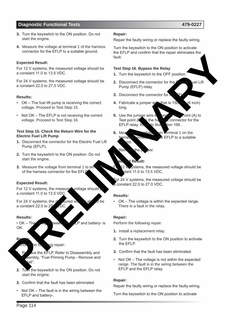
PRELIMIN
ARYDiagnostic Functional Tests 479-0227
Page 114
3. Turn the keyswitch to the ON position. Do not start the engine.
4. Measure the voltage at terminal 1 of the harness connector for the EFLP to a suitable ground.
Expected Result:For 12 V systems, the measured voltage should be a constant 11.0 to 13.5 VDC.
For 24 V systems, the measured voltage should be a constant 22.0 to 27.0 VDC.
Results:• OK – The fuel lift pump is receiving the correct
voltage. Proceed to Test Step 15.
• Not OK – The EFLP is not receiving the correct voltage. Proceed to Test Step 16.
Test Step 15. Check the Return Wire for the Electric Fuel Lift Pump1. Disconnect the connector for the Electric Fuel Lift
Pump (EFLP).
2. Turn the keyswitch to the ON position. Do not start the engine.
3. Measure the voltage from terminal 1 to terminal 2 of the harness connector for the EFLP.
Expected Result:For 12 V systems, the measured voltage should be a constant 11.0 to 13.5 VDC.
For 24 V systems, the measured voltage should be a constant 22.0 to 27.0 VDC.
Results:• OK – The wiring between the EFLP and battery- is OK.
Repair: Perform the following repair:
1. Replace the EFLP. Refer to Disassembly and Assembly, “Fuel Priming Pump - Remove and Install”.
2. Turn the keyswitch to the ON position. Do not start the engine.
3. Confirm that the fault has been eliminated.
• Not OK – The fault is in the wiring between the EFLP and battery-.
Repair: Repair the faulty wiring or replace the faulty wiring.
Turn the keyswitch to the ON position to activate the EFLP and confirm that the repair eliminates the fault.
Test Step 16. Bypass the Relay1. Turn the keyswitch to the OFF position.
2. Disconnect the connector for the Electric Fuel Lift Pump (EFLP) relay.
3. Disconnect the connector for the EFLP.
4. Fabricate a jumper wire that is 150 mm (6 inch) long.
5. Use the jumper wire to connect Test Point (A) to Test point (B) on the harness connector for the EFLP relay. Refer to Illustration 166 .
6. Measure the voltage from terminal 1 on the harness connector for the EFLP to a suitable ground.
7. Remove the jumper.
Expected Result:For 12 V systems, the measured voltage should be a constant 11.0 to 13.5 VDC.
For 24 V systems, the measured voltage should be a constant 22.0 to 27.0 VDC.
Results:• OK – The voltage is within the expected range.
There is a fault in the relay.
Repair: Perform the following repair:
1. Install a replacement relay.
2. Turn the keyswitch to the ON position to activate the EFLP.
3. Confirm that the fault has been eliminated.
• Not OK – The voltage is not within the expected range. The fault is in the wiring between the EFLP and the EFLP relay.
Repair: Repair the faulty wiring or replace the faulty wiring.
Turn the keyswitch to the ON position to activate

PRELIMIN
ARY479-0227 Diagnostic Functional Tests
Page 115
the EFLP and confirm that the repair eliminates the fault.
Glow Plug Starting Aid - Test (Customer Wiring)System Operation Description:This procedure covers the following diagnostic code:
Use this procedure if there is a suspected fault in the glow plug start aid circuit or the glow plugs.
Diagnostic Trouble Codes for the Glow Plug Start Aid Relay CircuitJ1939 Code
Description Notes
676-6 Engine Glow Plug Relay : Current Above Normal
The Electronic Control Module (ECM) detects the following conditions:The engine is not cranking.
The ECM has been powered for at least one second.There is a high current condition (short circuit) in the glow plug start aid
relay circuit for more than 2 seconds.If equipped, the warning light will come on. The diagnostic code will be
logged. An ECM that was previously blank will require a total of 2 hours of operation before the diagnostic code will be logged. The ECM is unable
to activate the relay for the glow plug starting aid. The glow plugs will not operate or the glow plugs will operate all the time. The engine may be difficult to start in cold temperatures and the exhaust may emit white
smoke.
The following background information is related to this procedure:
The starting aid is used to improve the engine starting when the engine is cold. With the keyswitch in the ON position, the ECM will monitor the coolant temperature and the engine intake manifold air temperature in order to decide if the glow plugs need to be switched ON. If the glow plugs are required, then the ECM will activate the starting aid relay for a controlled period. While the glow plug start aid relay is activated, the glow plug start aid relay will supply power to the glow plugs. If a “Wait To Start” lamp is installed, then this lamp will be illuminated in order to indicate the “Wait To Start” period.
The engine is equipped with ether injection. Glow plugs are used for temperatures that are between 5° C (41° F) and -25 °C (-13 °F). If the ambienttemperature is below -25 °C (-13 °F), the glow plugs are disabled and ether injection is used.
“Wait to Start Lamp”This feature may be included as an option.
When glow plugs need to be activated prior to starting, a lamp will indicate that the operator needs to “Wait to Start” . Starting aids may be used during the cranking of the engine. Starting aids may be used if the engine has previously been started. The “Wait to Start” lamp will not be active in these conditions.
Electronic Service Tool Test AidThe electronic service tool includes the test “Glow Plug Start Aid Override Test” . This test will assist the analysis of the cold starting aid.
Overview of the Glow Plug Start Aid Override TestThis glow plug start aid override test switches on the cold starting aid when the engine is not running. The glow plug start aid override test aids the analysis of the circuit for the glow plug start aid relay.

PRELIMIN
ARYDiagnostic Functional Tests 479-0227
Page 116
Schematic for the glow plug starting aid circuit
View of the pin locations on the P1 connector for the glow plug starting aid circuit
(20) Glow plug start aid control
(59) Return
Test Step 1. Inspect Electrical Connectors and Wiring1. Check that the fuses are not blown.
2. Inspect the terminals on the glow plug start aid relay and then inspect the connector on the flying lead from the relay. Refer to Troubleshooting, “Electrical Connectors - Inspect” for details.
3. Inspect the bus bar for the glow plugs. Ensure that the nuts that secure the bus bar to each glow plug are tightened to a torque of 2 N·m (17 lb in). Ensure that the bus bar is not shorted to
the engine.
4. Perform a 45 N (10 lb) pull test on each of the wires in the ECM connector that are associated with the glow plug starting aid.
5. Check the screw for the ECM connector for the correct torque of 6 N·m (53 lb in).
6. Check the harness for abrasion and pinch points from the glow plugs back to the ECM.
Results:• All connectors, pins, and sockets are correctly
coupled and/or inserted. The harness is free of corrosion, abrasion, and pinch points. The fuses are not blown. The bus bar is secured to the glow plugs and not shorted to ground. Proceed to Test Step 2.
• There is a fault with the harness and connectors.
Repair: Repair the connectors or the harness and/or replace the connectors or the harness. Ensure that all of the seals are correctly in place and ensure that the connectors are correctly connected. Replace blown fuses.
Use the electronic service tool in order to clear all logged diagnostic codes and then verify that the repair has eliminated the fault.
Test Step 2. Check for Active Diagnostic Codes1. Connect the electronic service tool to the
diagnostic connector.

PRELIMIN
ARY479-0227 Diagnostic Functional Tests
Page 117
2. Turn the keyswitch to the ON position.
Note: Do not start the engine.
3. Use the electronic service tool to select the “Glow Plug Start Aid Override Test” in order to turn on the power for the glow plugs.
4. Check for active diagnostic codes or recently logged diagnostic codes.
Results:• Diagnostic code 676-6 is active or recently
logged Proceed to Test Step 3.
• An active diagnostic code or a recently logged diagnostic code was not displayed. Proceed to Test Step 5.
Test Step 3. Disconnect the Relay1. Turn the keyswitch to the OFF position.
2. Disconnect the glow plug start aid relay.
3. Use the electronic service tool to select the “Glow Plug Start Aid Override Test” in order to turn on the power for the glow plugs.
4. Use the electronic service tool to check for an active 676-6 diagnostic code.
Results:• A 676-6 diagnostic code is active at this time. –
There is a short in the circuit for the relay coil. Proceed to Test Step 4.
• The 676-6 diagnostic code is not active with the relay disconnected. – There is a fault in the relay.
Repair: Perform the following repair:
1. Install a replacement relay.
2. Use the electronic service tool to perform the “Glow Plug Start Aid Override Test” .
3. Confirm that the fault has been eliminated.
Test Step 4. Disconnect the Relay at the ECM1. Disconnect the P1 connector.
2. Inspect the P1connector. Refer to Troubleshooting, “Electrical Connectors - Inspect” for details.
3. Remove the wire from P1:20.
4. Reconnect the P1 connector.
5. Use the electronic service tool to select the “Glow Plug Start Aid Override Test” in order to turn on the power for the glow plugs.
6. Use the electronic service tool to check for an active 676-6 diagnostic code.
Results:• A 676-6 diagnostic code is active at this time. –
The wiring for the glow plug start aid relay is not shorted. Proceed to Test Step 8.
• The 676-6 diagnostic code is no longer active. – The wiring between P1:20 and the ECM is shorted.
Repair: Perform the following repair:
1. Repair the faulty wiring or replace the faulty wiring.
2. Use the electronic service tool to perform the “Glow Plug Start Aid Override Test” .
3. Confirm that the fault has been eliminated.
Test Step 5. Check the Operation of the Glow Plugs1. Place a suitable clamp-on ammeter on the power
supply wire.
2. Use the electronic service tool to select the “Glow Plug Start Aid Override Test” in order to turn on the power for the glow plugs.
3. Wait for 20 seconds and then note the reading on the Clamp-on ammeter.
Expected Result:For a 12 V system , the ammeter reading is approximately 7.0 Amps.
For a 24 V system , the ammeter reading is approximately 4.5 Amps.
Results:• The reading on the clamp-on ammeter is zero. –
There is a fault in the circuit for the glow plugs. Proceed to Test Step 6.
• The reading on the clamp-on ammeter is between zero and the expected reading for the system. Proceed to Test Step 9.
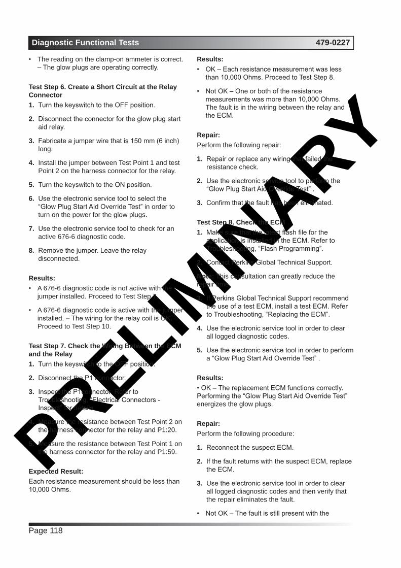
PRELIMIN
ARYDiagnostic Functional Tests 479-0227
Page 118
• The reading on the clamp-on ammeter is correct. – The glow plugs are operating correctly.
Test Step 6. Create a Short Circuit at the Relay Connector1. Turn the keyswitch to the OFF position.
2. Disconnect the connector for the glow plug start aid relay.
3. Fabricate a jumper wire that is 150 mm (6 inch) long.
4. Install the jumper between Test Point 1 and test Point 2 on the harness connector for the relay.
5. Turn the keyswitch to the ON position.
6. Use the electronic service tool to select the “Glow Plug Start Aid Override Test” in order to turn on the power for the glow plugs.
7. Use the electronic service tool to check for an active 676-6 diagnostic code.
8. Remove the jumper. Leave the relay disconnected.
Results:• A 676-6 diagnostic code is not active with the
jumper installed. Proceed to Test Step 7.
• A 676-6 diagnostic code is active with the jumper installed. – The wiring for the relay coil is OK. Proceed to Test Step 10.
Test Step 7. Check the Wiring Between the ECM and the Relay1. Turn the keyswitch to the OFF position.
2. Disconnect the P1 connector.
3. Inspect the P1connector. Refer to Troubleshooting, “Electrical Connectors - Inspect” for details.
4. Measure the resistance between Test Point 2 on the harness connector for the relay and P1:20.
5. Measure the resistance between Test Point 1 on the harness connector for the relay and P1:59.
Expected Result:Each resistance measurement should be less than 10,000 Ohms.
Results:• OK – Each resistance measurement was less
than 10,000 Ohms. Proceed to Test Step 8.
• Not OK – One or both of the resistance measurements was more than 10,000 Ohms. The fault is in the wiring between the relay and the ECM.
Repair: Perform the following repair:
1. Repair or replace any wiring that failed the resistance check.
2. Use the electronic service tool to perform the “Glow Plug Start Aid Override Test” .
3. Confirm that the fault has been eliminated.
Test Step 8. Check the ECM1. Make sure that the latest flash file for the
application is installed in the ECM. Refer to Troubleshooting, “Flash Programming”.
2. Contact Perkins Global Technical Support.
Note: This consultation can greatly reduce the repair time.
3. If Perkins Global Technical Support recommend the use of a test ECM, install a test ECM. Refer to Troubleshooting, “Replacing the ECM”.
4. Use the electronic service tool in order to clear all logged diagnostic codes.
5. Use the electronic service tool in order to perform a “Glow Plug Start Aid Override Test” .
Results:• OK – The replacement ECM functions correctly. Performing the “Glow Plug Start Aid Override Test” energizes the glow plugs.
Repair: Perform the following procedure:
1. Reconnect the suspect ECM.
2. If the fault returns with the suspect ECM, replace the ECM.
3. Use the electronic service tool in order to clear all logged diagnostic codes and then verify that the repair eliminates the fault.
• Not OK – The fault is still present with the

PRELIMIN
ARY479-0227 Diagnostic Functional Tests
Page 119
replacement ECM. Do not use the replacement ECM.
Repair: Contact Perkins Global Technical Support.
Test Step 9. Test the Continuity of the Glow Plugs1. Disconnect the power supply and remove the
bus bar from the glow plugs.
2. Use a suitable digital multimeter to check continuity (resistance). Turn the audible signal on the digital multimeter ON.
3. Place one probe on the connection for one of the glow plugs and the other probe to a suitable ground. The digital multimeter should make an audible sound.
4. Repeat the continuity check on the remaining glow plugs.
Expected Result:One or more glow plugs do not have continuity.
Results:• OK Proceed to Test Step 1.
• Not OK – One or more of the glow plugs do not display continuity.
Repair: Perform the following procedure:
1. Replace any glow plugs that do not display continuity.
2. Confirm that the fault has been eliminated.
Test Step 10. Check the Relay Coil for an Open Circuit1. Turn the keyswitch to the OFF position.
2. Measure the resistance from Test Point 1 to Test Point 2 on the harness connector for the glow plug start aid relay.
3. Switch the probes of the ohmmeter and measure the resistance from Test Point 2 to Test Point 1 on the harness connector for the relay.
Expected Result:Both resistance measurements should be less than 10,000 Ohms.
Results:• OK – Both resistance measurements are less
than 10,000 Ohms. Proceed to Test Step 11.
• Not OK – One of the resistance measurements was more than 10,000 Ohms. The fault is in the relay coil.
Repair: Perform the following repair:
1. Install a replacement relay.
2. Use the electronic service tool to perform the “Glow Plug Start Aid Override Test” .
3. Confirm that the fault has been eliminated.
Test Step 11. Check the Fuse (Customer Fit)1. Turn the battery disconnect switch to the OFF
position.
2. Check the fuse for the glow plug start aid relay.
Refer to Illustration.
Results:• The fuse is blown. – There is a short in the power
circuit for the glow plugs. Proceed to Test Step 12.
• The fuse is not blown – There may be an open circuit in the power circuit for the glow plugs. Proceed to Test Step 14.
Test Step 12. Disconnect the Relay and Check the Fuse1. Disconnect the glow plug start aid relay.
2. Replace the fuse for the relay.
3. Turn the battery disconnect switch to the ON position. Wait for 5 seconds.
4. Turn the battery disconnect switch to the OFF position.
5. Check the fuse.
Results:• The fuse is blown. – There is a short circuit in the
wiring between the fuse and the glow plug start aid relay.
Repair: Perform the following repair:

PRELIMIN
ARYDiagnostic Functional Tests 479-0227
Page 120
1. Repair the faulty wiring or replace the faulty wiring. Replace the fuse. Reconnect the relay.
2. Turn the battery disconnect switch to the ON position. Turn the keyswitch to the ON position.
3. Use the electronic service tool to perform the “Glow Plug Start Aid Override Test” .
4. Confirm that the fault has been eliminated.
• The fuse is not blown. – The wiring between the fuse and the relay is OK. Proceed to Test Step 13.
Test Step 13. Check the Wiring between the Relay and the Bus Bar for a Short Circuit1. Disconnect the power supply wire from the bus
bar.
2. Measure the resistance between Test Point B on the harness connector for the relay to a suitable ground.
Expected Result:The resistance should be more than 10,000 Ohms.
Results:• OK – The resistance is more than 10,000 Ohms. The wiring between the relay and the bus bar is not shorted. The fault is in the relay.
Repair: Perform the following repair:
1. Install a replacement relay. Reconnect the power supply wire to the bus bar.
2. Turn the battery disconnect switch to the ON position. Turn the keyswitch to the ON position. Reconnect the relay.
3. Use the electronic service tool to perform the “Glow Plug Start Aid Override Test” .
4. Confirm that the fault has been eliminated.
• Not OK – The resistance is less than 10,000 Ohms. The wiring between the relay and the bus bar is shorted.
Repair: Perform the following repair:
1. Repair the faulty wiring or replace the faulty wiring. Reconnect the relay.
2. Turn the battery disconnect switch to the ON position. Turn the keyswitch to the ON position.
3. Use the electronic service tool to perform the “Glow Plug Start Aid Override Test” .
4. Confirm that the fault has been eliminated.
Test Step 14. Check the Input Voltage to the Relay1. Disconnect the connector for the glow plug start
aid relay.
2. Turn the battery disconnect switch to the ON position.
3. Measure the voltage at Test Point A on the harness connector for the relay to a suitable ground.
Expected Result:For 12 V systems, the measured voltage should be a constant 11.0 to 13.5 VDC.
For 24 V systems, the measured voltage should be a constant 22.0 to 27.0 VDC.
Results:• OK – The voltage is within the expected range.
The wiring between the battery and the relay is OK. Proceed to Test Step 15.
• Not OK – The voltage is not within the expected range. The fault is in the wiring between the battery and the relay.
Repair: Perform the following repair:
1. Repair the faulty wiring or replace the faulty wiring.
2. Turn the keyswitch to the ON position. Reconnect the relay.
3. Use the electronic service tool to perform the “Glow Plug Start Aid Override Test” .
4. Confirm that the fault has been eliminated.
Test Step 15. Bypass the Relay1. Turn the battery disconnect switch to the OFF
position.
2. Fabricate an 8 AWG jumper wire that is 150 mm (6 inch) long.
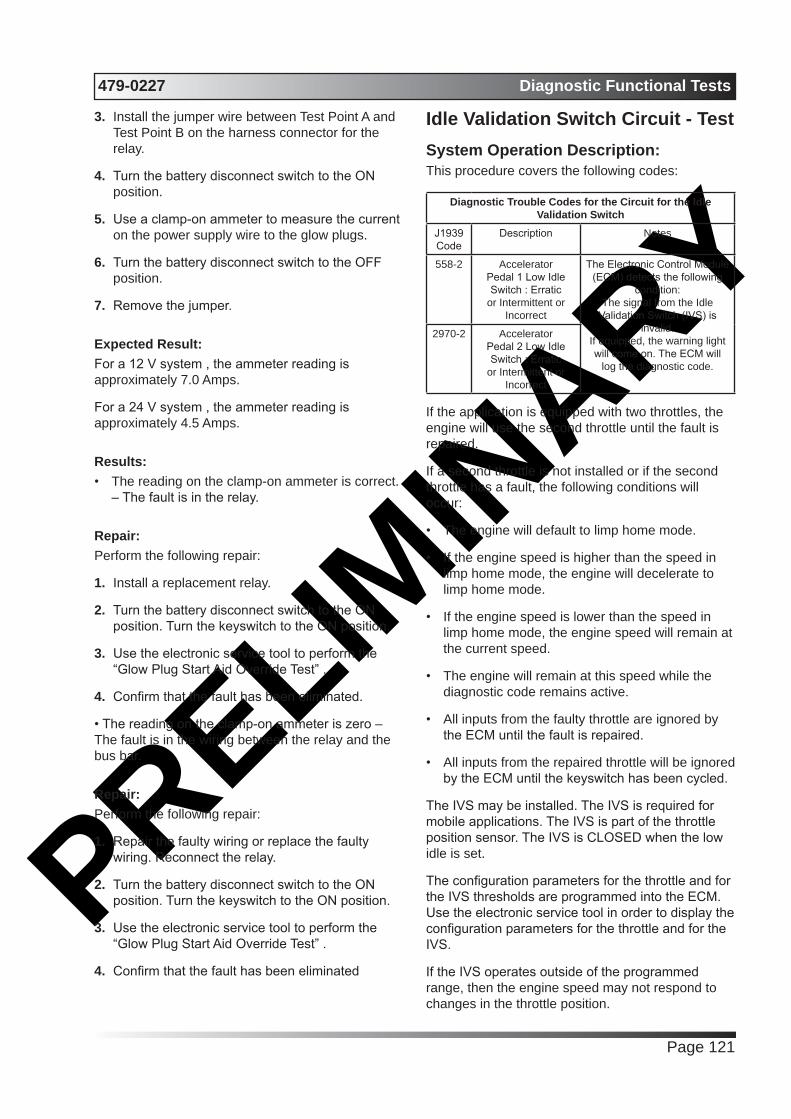
PRELIMIN
ARY479-0227 Diagnostic Functional Tests
Page 121
3. Install the jumper wire between Test Point A and Test Point B on the harness connector for the relay.
4. Turn the battery disconnect switch to the ON position.
5. Use a clamp-on ammeter to measure the current on the power supply wire to the glow plugs.
6. Turn the battery disconnect switch to the OFF position.
7. Remove the jumper.
Expected Result:For a 12 V system , the ammeter reading is approximately 7.0 Amps.
For a 24 V system , the ammeter reading is approximately 4.5 Amps.
Results:• The reading on the clamp-on ammeter is correct.
– The fault is in the relay.
Repair: Perform the following repair:
1. Install a replacement relay.
2. Turn the battery disconnect switch to the ON position. Turn the keyswitch to the ON position.
3. Use the electronic service tool to perform the “Glow Plug Start Aid Override Test” .
4. Confirm that the fault has been eliminated.
• The reading on the clamp-on ammeter is zero – The fault is in the wiring between the relay and the bus bar.
Repair: Perform the following repair:
1. Repair the faulty wiring or replace the faulty wiring. Reconnect the relay.
2. Turn the battery disconnect switch to the ON position. Turn the keyswitch to the ON position.
3. Use the electronic service tool to perform the “Glow Plug Start Aid Override Test” .
4. Confirm that the fault has been eliminated
Idle Validation Switch Circuit - TestSystem Operation Description:This procedure covers the following codes:
Diagnostic Trouble Codes for the Circuit for the Idle Validation Switch
J1939 Code
Description Notes
558-2 Accelerator Pedal 1 Low Idle Switch : Erratic
or Intermittent or Incorrect
The Electronic Control Module (ECM) detects the following
condition:The signal from the Idle
Validation Switch (IVS) is invalid.
If equipped, the warning light will come on. The ECM will
log the diagnostic code.
2970-2 Accelerator Pedal 2 Low Idle Switch : Erratic
or Intermittent or Incorrect
If the application is equipped with two throttles, the engine will use the second throttle until the fault is repaired.
If a second throttle is not installed or if the second throttle has a fault, the following conditions will occur:
• The engine will default to limp home mode.
• If the engine speed is higher than the speed in limp home mode, the engine will decelerate to limp home mode.
• If the engine speed is lower than the speed in limp home mode, the engine speed will remain at the current speed.
• The engine will remain at this speed while the diagnostic code remains active.
• All inputs from the faulty throttle are ignored by the ECM until the fault is repaired.
• All inputs from the repaired throttle will be ignored by the ECM until the keyswitch has been cycled.
The IVS may be installed. The IVS is required for mobile applications. The IVS is part of the throttle position sensor. The IVS is CLOSED when the low idle is set.
The configuration parameters for the throttle and for the IVS thresholds are programmed into the ECM. Use the electronic service tool in order to display the configuration parameters for the throttle and for the IVS.
If the IVS operates outside of the programmed range, then the engine speed may not respond to changes in the throttle position.

PRELIMIN
ARYDiagnostic Functional Tests 479-0227
Page 122
(40) Idle validation 2
Test Step 1. Check for Active Diagnostic Codes and/or Recently Logged Diagnostic Codes1. Connect the electronic service tool to the service
tool connector.
2. Turn the keyswitch to the ON position
3. Monitor the active diagnostic code screen on the electronic service tool. Check and record any active diagnostic codes.
Note: Wait at least 30 seconds in order for the diagnostic codes to become active.
Note: A diagnostic code that is logged several times is an indication of an intermittent problem. Most intermittent problems are the result of a poor connection between a socket and a pin in a connector or of a poor connection between a wire and a terminal.
The electronic service tool may be used for the following:
• If necessary, reset the IVS threshold for an existing IVS.
• If necessary, view the IVS change point and reset the IVS thresholds when a new throttle assembly is installed.
Schematic of the IVS circuit
View of the pin locations in the P1 connector for the IVS
(18) Sensor Ground(22) Idle validation 1
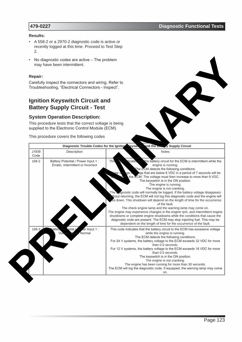
PRELIMIN
ARY479-0227 Diagnostic Functional Tests
Page 123
Results:• A 558-2 or a 2970-2 diagnostic code is active or
recently logged at this time. Proceed to Test Step 2.
• No diagnostic codes are active – The problem may have been intermittent.
Repair: Carefully inspect the connectors and wiring. Refer to Troubleshooting, “Electrical Connectors - Inspect”.
Ignition Keyswitch Circuit and Battery Supply Circuit - TestSystem Operation Description:This procedure tests that the correct voltage is being supplied to the Electronic Control Module (ECM).
This procedure covers the following codes
Diagnostic Trouble Codes for the Ignition Keyswitch and the Battery Supply CircuitJ1939 Code
Description Notes
168-2 Battery Potential / Power Input 1 : Erratic, Intermittent or Incorrect
This code indicates that the battery circuit for the ECM is intermittent while the engine is running.
The ECM detects the following conditions:Three voltage readings that are below 6 VDC in a period of 7 seconds will be detected by the ECM. The voltage must then increase to more than 9 VDC.
The keyswitch is in the ON position.The engine is running.
The engine is not cranking.The diagnostic code will normally be logged. If the battery voltage disappears without returning, the ECM will not log this diagnostic code and the engine will shut down. This shutdown will depend on the length of time for the occurrence
of the fault.The check engine lamp and the warning lamp may come on.
The engine may experience changes in the engine rpm, and intermittent engine shutdowns or complete engine shutdowns while the conditions that cause the diagnostic code are present. The ECM may stop injecting fuel. This may be
dependent on the length of time for the occurrence of the fault.
168-3 Battery Potential / Power Input 1 : Voltage Above Normal
This code indicates that the battery circuit to the ECM has excessive voltage while the engine is running.
The ECM detects the following conditions:For 24 V systems, the battery voltage to the ECM exceeds 32 VDC for more
than 0.5 seconds.For 12 V systems, the battery voltage to the ECM exceeds 16 VDC for more
than 0.5 seconds.The keyswitch is in the ON position.
The engine is not cranking.The engine has been running for more than 30 seconds.
The ECM will log the diagnostic code. If equipped, the warning lamp may come on.

PRELIMIN
ARYDiagnostic Functional Tests 479-0227
Page 124
168-4 Battery Potential / Power Input 1 : Voltage Below Normal
This code indicates that the battery circuit for the ECM has low voltage while the engine is running.
The ECM detects the following conditions:For 24 V systems, the battery voltage to the ECM is below 18 VDC for more
than 0.5 seconds.For 12 V systems, the battery voltage to the ECM is below 9 VDC for more than
0.5 seconds.The keyswitch is in the ON position.
The engine is not cranking.The engine has been running for more than 3 seconds.
If equipped, the warning lamp may come on. The ECM will normally log the diagnostic code. If battery voltage disappears without returning, the ECM will not
log this diagnostic code and the engine will shut down.The engine will derate 100 percent.
The engine may experience changes in the engine rpm, and intermittent engine shutdowns or complete engine shutdowns while the conditions that cause this
diagnostic code are present.
The ECM receives electrical power (battery voltage) through the wiring that is supplied by the manufacturer of the application. Unswitched battery+ voltage is supplied through P1: 48, 52, 53, 55, and 57. The battery- is supplied through P1: 61, 63, 65, 67, and 69. The ECM receives the input from the keyswitch at P1:70 when the keyswitch is in the ON position or in the START position. When the ECM detects battery voltage at this input, the ECM will power up. When battery voltage is removed from this input, the ECM will power down.
The cause of an intermittent power supply to the ECM can occur on either the positive side or on the negative side of the battery circuit. The connections for the unswitched battery+ may be routed through a dedicated protection device (circuit breaker).
Some applications may be equipped with an engine protection shutdown system or an idle timer shutdown system that interrupts electrical power to the keyswitch. The engine protection shutdown system can be an aftermarket device and the idle timer shutdown system can be external to the ECM. Some of these systems will not supply power to the ECM until one of the following conditions is met:
• The engine is cranking.
• The engine oil pressure achieves acceptable limits.
• An override button is pressed.
These devices may be the cause of intermittent power to the ECM. These devices may also shut down the engine.
Usually, battery power to the diagnostic connector is available and the battery power to the data link connector is independent of the keyswitch. Therefore, although the electronic service tool can be powered up, there may be no communication with the engine ECM. The engine ECM requires
the keyswitch to be in the ON position in order to maintain communications. The ECM may power down a short time after connecting the electronic service tool if the keyswitch is in the OFF position.
For intermittent faults such as intermittent shutdowns that could be caused by the application wiring, temporarily bypassing the application wiring may be an effective means of determining the root cause. If the symptoms disappear with the bypass wiring, the application wiring is the cause of the fault. A means of bypassing the application wiring is explained in this test procedure. This procedure is especially important for applications that do not provide dedicated circuits for the unswitched battery and the connections for the keyswitch.

PRELIMIN
ARY479-0227 Diagnostic Functional Tests
Page 125
Schematic for the ignition keyswitch and battery supply circuit
View of the pin locations on the P1 connector for the ignition keyswitch and battery supply circuit
(48) Battery+
(52) Battery+
(53) Battery+
(55) Battery+
(57) Battery+

PRELIMIN
ARYDiagnostic Functional Tests 479-0227
Page 126
(61) Battery ground
(63) Battery ground
(65) Battery ground
(67) Battery ground
(69) Battery ground
(70) Ignition key switch
Test Step 1. Inspect Electrical Connectors and Wiring1. Thoroughly inspect the battery connections
and the connections to the keyswitch. Refer to Troubleshooting, “Electrical Connectors - Inspect” for details.
2. Perform a 45 N (10 lb) pull test on each of the wires in the ECM connector that are associated with the following connections:
• P1: 48, 52, 53, 55, 57 (Unswitched Battery+)
• P1: 61, 63, 65, 67, 69 (Battery-)
• P1:70 (keyswitch)
3. Use the electronic service tool to perform a “Wiggle Test” .
4. Check the ECM connector for the correct torque of 6 N·m (53 lb in).
5. Check the harness for abrasion and for pinch points from the battery to the ECM, and from the keyswitch to the ECM.
Results:• All connectors, pins, and sockets are correctly
connected and/or inserted and the harness is free of corrosion, of abrasion or of pinch points. Proceed to Test Step 2.
• There is a fault with the connectors and/or the harness.
Repair:Repair the connectors or the harness and/or replace the connectors or the harness. Ensure that all of the seals are correctly in place and ensure that the connectors are correctly connected.
Use the electronic service tool in order to clear all logged diagnostic codes and then verify that the repair eliminates the fault.
Test Step 2. Check for Active Diagnostic Codes or Logged Diagnostic Codes1. Connect the electronic service tool to the
diagnostic connector.
2. Turn the keyswitch to the ON position.
3. Monitor the active diagnostic code screen on the electronic service tool. Check and record any active diagnostic codes or logged diagnostic codes.
Note: Wait at least 30 seconds in order for the diagnostic codes to become active.
Expected Result:One of the following diagnostic codes is active or logged:
• 168-2Battery Potential / Power Input 1 : Erratic, Intermittent or Incorrect
• 168-3Battery Potential / Power Input 1 : Voltage Above Normal
• 168-4Battery Potential / Power Input 1 : Voltage Below Normal
Results:• One of the preceding diagnostic codes is active
or logged Proceed to Test Step 3.
• No diagnostic code is active.
Repair: The fault is no longer present. If the fault is intermittent, refer to Troubleshooting, “Electrical Connectors - Inspect”.
Test Step 3. Check the Batteries 1. Load-test the batteries. Use a suitable battery
load tester. Refer to Systems Operation, Testing and Adjusting, “Battery - Test” for the correct procedure.
Results:• The batteries pass the load test. For 12 V
systems, the measured voltage is at least 11.0 VDC. For 24 V systems, the measured voltage is at least 22.0 VDC Proceed to Test Step 4.
• The batteries do not pass the load test. For 12 V systems, the measured voltage is less than 11.0 VDC. For 24 V systems, the measured voltage is less than 22.0 VDC.

PRELIMIN
ARY479-0227 Diagnostic Functional Tests
Page 127
Repair: Recharge or replace the faulty batteries.
Use the electronic service tool in order to clear all logged diagnostic codes and then verify that the repair eliminates the fault.
Test Step 4. Check the Battery Voltage at the ECM Connector1. Disconnect the P1 connector from the ECM.
2. Turn the keyswitch to the ON position.
Note: For 12 V systems, the measured voltage should be a constant 11.0 to 13.5 VDC.
Note: For 24 V systems, the measured voltage should be a constant 22.0 to 27.0 VDC.
3. Measure the voltage between P1:48 (Unswitched Battery+) and P1:61 (Battery-).
4. Measure the voltage between P1:52 (Unswitched Battery+) and P1:63 (Battery-).
5. Measure the voltage between P1:53 (Unswitched Battery+) and P1:65 (Battery-).
6. Measure the voltage between P1:55 (Unswitched Battery+) and P1:67 (Battery-).
7. Measure the voltage between P1:57 (Unswitched Battery+) and P1:69 (Battery-).
8. Measure the voltage between P1:70 (keyswitch) and P1:65 (Battery-).
9. Turn the keyswitch to the OFF position.
Results:• The measured voltage is within the expected
range – The ECM is receiving the correct voltage.
Repair: If an intermittent fault is suspected, refer to Troubleshooting, “Electrical Connectors - Inspect”.
• The ECM is not receiving the correct voltage or no voltage was present on P1: 48, 52, 53 55, 57. Proceed to Test Step 5.
Test Step 5. Bypass the Application Harness
WARNING
Batteries give off flammable fumes which can explode.
To avoid injury or death, do not strike a match,
cause a spark, or smoke in the vicinity of a battery.
NOTICE
Do not connect the bypass harness to the battery until all of the in-line fuses have been removed from the Battery + line. If the fuses are not removed before connection to the battery, a spark may result.
Note: This bypass harness is only for test applications. This bypass harness must be removed before the application is released to the customer. The bypass harness can be used to determine if the intermittent problem is caused by interruptions in power to the ECM or to the keyswitch circuit.

PRELIMIN
ARYDiagnostic Functional Tests 479-0227
Page 128
Schematic for the bypass application harness
1. Turn the keyswitch to the OFF position.
2. Disconnect the P1 connector from the ECM.
3. Connect a bypass harness to the ECM.
4. Remove the fuses from the Battery+ wire of the bypass harness and connect the Battery+ and the Battery- wires directly to the battery terminals.
Note: This bypass directly connects the circuit for the keyswitch to the ECM. The ECM will remain powered until the connection to the unswitched battery+ line is disconnected. Remove the fuses from the in-line fuse holder to power down the ECM. Do not connect the bypass to the battery terminals or do not remove the bypass from the battery terminals without first removing the in-line fuses.
5. Use a multimeter to measure the voltage between P2:46 and ground. The voltage should be +5 VDC.
Note: Remove the bypass harness and restore all wiring to the original condition after testing.
Results:The measured voltage between P2:46 and ground is +5 VDC. The symptoms disappear when the bypass harness is installed. Also, the symptoms return when the bypass harness is removed. – The fault is
in the wiring for the application that supplies power to the ECM. Check for aftermarket engine protection switches that interrupt power.
Repair: Repair the faulty wiring or replace the faulty wiring.
• The measured voltage between P2:46 and ground is not +5 VDC.
Repair: Perform the following procedure:
1. Connect the bypass to another battery and verify if the fault is resolved. If the fault is resolved, the fault is with the batteries on the application.
2. If the fault still exists, make sure that the latest flash file for the application is installed in the ECM. Refer to Troubleshooting, “Flash Programming”.
3. Contact Perkins Global Technical Support.
Note: This consultation can greatly reduce the repair time.
4. If Perkins Global Technical Support recommend the use of a test ECM, install a test ECM. Refer to Troubleshooting, “Replacing the ECM”.

PRELIMIN
ARY479-0227 Diagnostic Functional Tests
Page 129
5. Use the electronic service tool to recheck the system for active diagnostic codes.
6. If the fault is resolved with the test ECM, reconnect the suspect ECM.
7. G. If the fault returns with the suspect ECM, replace the ECM.
8. H. Use the electronic service tool in order to clear all logged diagnostic codes and then verify that the repair eliminates the fault.
Indicator Lamp Circuit - TestSystem Operation Description:Use this procedure under the following circumstances:
• The lamps are not receiving battery voltage.
• The lamps are not operating correctly.
The following diagnostic lamps are available:
• Coolant temperature lamp
• Shutdown lamp
• Warning lamp
• Maintenance lamp
• Low oil pressure lamp
• Overspeed lamp
The electronic service tool can be used as a diagnostic aid in order to switch the individual lamps ON and OFF.
Note: The diagnostic aid that switches the lamps is contained in the “Override” section in the “diagnostics” menu of the electronic service tool.

PRELIMIN
ARYDiagnostic Functional Tests 479-0227
Page 130
Schematic of the circuit for the indicator lamps
Typical example of the pin locations on the P1 connector for the indicator lamps
(13) Overspeed lamp
(19) Coolant temp lamp
(28) Shutdown lamp
(29) Warning lamp
(31) Maintenance lamp
(36) Low oil pressure lamp

PRELIMIN
ARY479-0227 Diagnostic Functional Tests
Page 131
(48) Battery (+)
(52) Battery (+)
(53) Battery (+)
(55) Battery (+)
(57) Battery (+)
(61) Ground
(63) Ground
(65) Ground
(67) Ground
(69) Ground
(70) Ignition keyswitch
Test Step 1. Inspect Electrical Connectors and Wiring1. Turn the keyswitch to the OFF position.
2. Thoroughly inspect the P1 connector and the lamp connections. Refer to Troubleshooting, “Electrical Connectors - Inspect” for details.
3. Perform a 45 N (10 lb) pull test on each of the wires in the P1 connector that are associated with the indicator lamps.
4. Check the screw for the P1 connector for the correct torque of 6 N·m (53 lb in).
5. Check the harness for abrasions and for pinch points from the battery to the ECM.
Results:• OK Proceed to Test Step 2.
• Not OK
Repair: Repair the connectors or the harness and/or replace the connectors or the harness. Ensure that all of the seals are correctly in place and ensure that the connectors are correctly connected.
Verify that the repair eliminates the fault.
Test Step 2. Inspect the Lamp, the Fuse, and the Power Supply1. Disconnect the lamp from the harness. Inspect
the lamp in order to determine if the lamp has failed.
2. Measure the resistance across the two terminals of the lamp. If the resistance is more than 2000 Ohms, the bulb has failed.
3. Check the battery by connecting a test lamp across the terminal of the battery.
Results:• The lamp has less than 2000 Ohms resistance
and the power supply is OK. – The lamp appears to be operating correctly at this time. Proceed to Test Step 3.
• The lamp does not have less than 2000 Ohms resistance or the power supply is not OK.
Repair: Replace the suspect component or repair the suspect component. Verify that the repairs have eliminated the fault.
Test Step 3. Measure the Input to the Lamp at the Lamp Socket1. Turn the keyswitch to the ON position.
2. Use the electronic service tool to select the “override” function in order to switch individual lamps ON and OFF.
Note: The “Override” function is contained in the “Diagnostics” menu of the electronic service tool.
3. Measure the voltage at the lamp socket.
Results:• The voltage is between 12.0 VDC and 24.0 VDC.
Repair: Replace the bulb.
Verify that the repair eliminates the fault.
If the fault persists, measure the resistance across the two terminals of the lamp. If the resistance is more than 2000 Ohms, the replacement bulb has failed. Replace the bulb and repeat the test. Proceed to Test Step 4.
• The voltage is not between 12 VDC and 24 VDC – Proceed to Test Step 5.
Test Step 4. Test the Individual Lamp Circuits1. Disconnect the P1 connector.
2. Temporarily disconnect the wire from the P1 connector socket that is connected to the
PRELIMIN
ARYDiagnostic Functional Tests 479-0227
Page 132
suspect lamp.
3. By using a jumper wire, connect the removed wire to the battery-.
4. Turn the keyswitch to the ON position and observe the lamp.
Results:• The diagnostic lamp comes on while the jumper
is connected. Also, the diagnostic lamp goes off when the jumper is removed – The circuit for the diagnostic lamp is functioning correctly. Proceed to Test Step 5.
• The lamp did not turn ON. – The lamp circuit is not functioning correctly. There is a fault in the harness between the lamp and the ECM.
Repair: Repair the lamp circuit.
Verify that the repair eliminated the fault.
Test Step 5. Check the Voltage at the ECM1. Disconnect the P1 connector.
2. Temporarily disconnect the wire from the P1 connector that supplies the suspect lamp.
3. Fabricate the jumper wire with a suitable pin for the P1 connector.
4. Install one end of the jumper wire into the P1 connector socket that is connected to the suspect lamp. Connect a voltage test lamp between the battery+ and the jumper wire.
Note: The “Override” function is contained in the “Diagnostics” menu of the electronic service tool.
Results:• The lamp comes ON – The ECM is operating correctly. There is a fault in the wiring or the lamp. Repair the wiring or the lamp, as required. Verify that the repair eliminates the fault.
• The lamp does not come ON – The ECM is faulty.
Repair: Perform the following repair:
1. Make sure that the latest flash file for the application is installed in the ECM. Refer to Troubleshooting, “Flash Programming”.
2. Contact Perkins Global Technical Support.
Note: This consultation can greatly reduce the repair time.
3. If Perkins Global Technical Support recommend the use of a test ECM, install a test ECM. Refer to Troubleshooting, “Replacing the ECM”.
4. Use the electronic service tool to recheck the
5. If the fault is resolved with the test ECM, reconnect the suspect ECM.
6. If the fault returns with the suspect ECM, replace the ECM.
7. Use the electronic service tool in order to clear all logged diagnostic codes and then verify that the repair eliminates the fault.
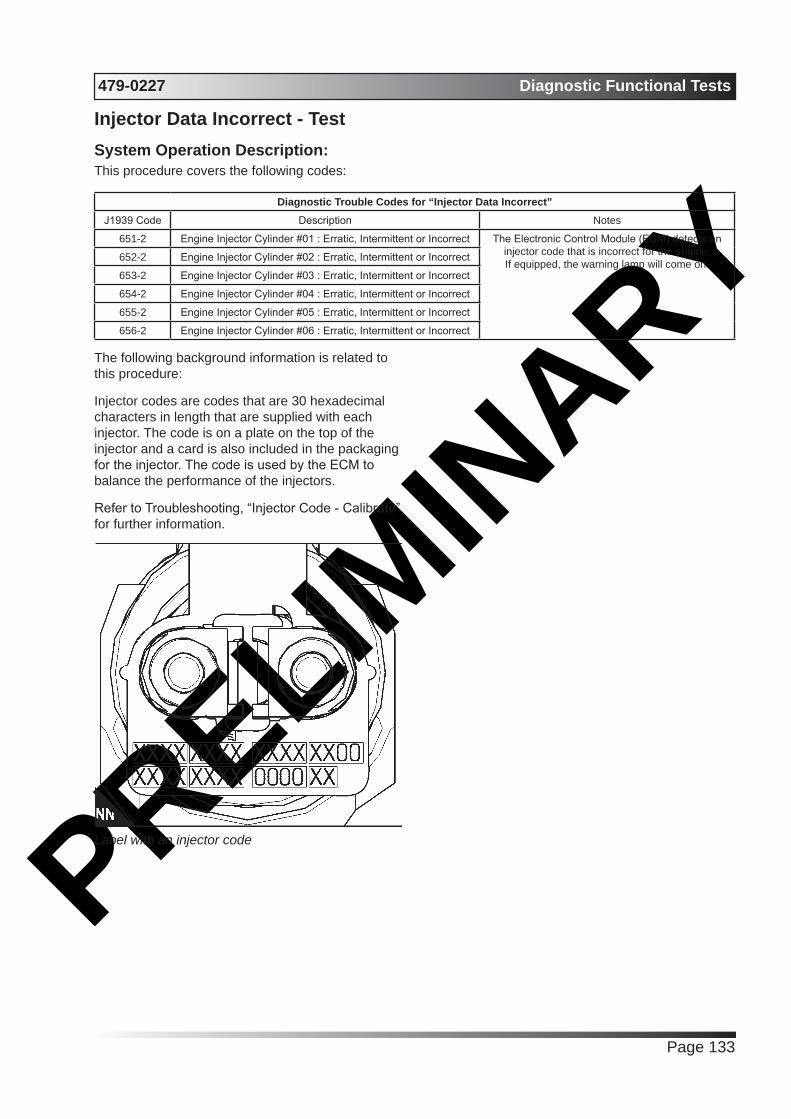
PRELIMIN
ARY479-0227 Diagnostic Functional Tests
Page 133
Injector Data Incorrect - TestSystem Operation Description:This procedure covers the following codes:
Diagnostic Trouble Codes for “Injector Data Incorrect”J1939 Code Description Notes
651-2 Engine Injector Cylinder #01 : Erratic, Intermittent or Incorrect The Electronic Control Module (ECM) detects an injector code that is incorrect for the engine.If equipped, the warning lamp will come on.
652-2 Engine Injector Cylinder #02 : Erratic, Intermittent or Incorrect
653-2 Engine Injector Cylinder #03 : Erratic, Intermittent or Incorrect
654-2 Engine Injector Cylinder #04 : Erratic, Intermittent or Incorrect
655-2 Engine Injector Cylinder #05 : Erratic, Intermittent or Incorrect
656-2 Engine Injector Cylinder #06 : Erratic, Intermittent or Incorrect
The following background information is related to this procedure:
Injector codes are codes that are 30 hexadecimal characters in length that are supplied with each injector. The code is on a plate on the top of the injector and a card is also included in the packaging for the injector. The code is used by the ECM to balance the performance of the injectors.
Refer to Troubleshooting, “Injector Code - Calibrate” for further information.
Label with an injector code
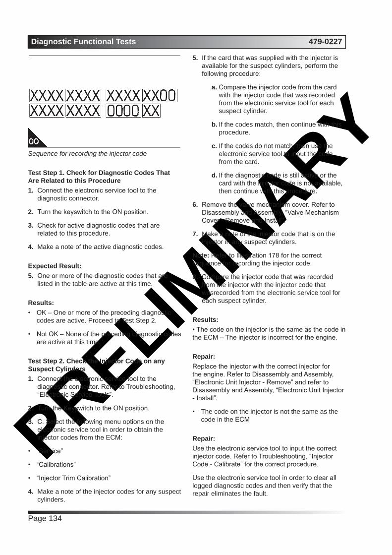
PRELIMIN
ARYDiagnostic Functional Tests 479-0227
Page 134
Sequence for recording the injector code
Test Step 1. Check for Diagnostic Codes That Are Related to this Procedure1. Connect the electronic service tool to the
diagnostic connector.
2. Turn the keyswitch to the ON position.
3. Check for active diagnostic codes that are related to this procedure.
4. Make a note of the active diagnostic codes.
Expected Result:5. One or more of the diagnostic codes that are
listed in the table are active at this time.
Results:• OK – One or more of the preceding diagnostic
codes are active. Proceed to Test Step 2.
• Not OK – None of the preceding diagnostic codes are active at this time.
Test Step 2. Check the Injector Code on any Suspect Cylinders1. Connect the electronic service tool to the
diagnostic connector. Refer to Troubleshooting, “Electronic Service Tools”.
2. Turn the Keyswitch to the ON position.
3. C. Select the following menu options on the electronic service tool in order to obtain the injector codes from the ECM:
• “Service”
• “Calibrations”
• “Injector Trim Calibration”
4. Make a note of the injector codes for any suspect cylinders.
5. If the card that was supplied with the injector is available for the suspect cylinders, perform the following procedure:
a. Compare the injector code from the card with the injector code that was recorded from the electronic service tool for each suspect cylinder.
b. If the codes match, then continue with this procedure.
c. If the codes do not match, then use the electronic service tool to input the code from the card.
d. If the diagnostic code is still active or the card with the injector code is not available, then continue with this procedure.
6. Remove the valve mechanism cover. Refer to Disassembly and Assembly, “Valve Mechanism Cover - Remove and Install”.
7. Make a note of the injector code that is on the injector in any suspect cylinders.
Note: Refer to Illustration 178 for the correct sequence for recording the injector code.
8. Compare the injector code that was recorded from the injector with the injector code that wasrecorded from the electronic service tool for each suspect cylinder.
Results:• The code on the injector is the same as the code in the ECM – The injector is incorrect for the engine.
Repair: Replace the injector with the correct injector for the engine. Refer to Disassembly and Assembly, “Electronic Unit Injector - Remove” and refer to Disassembly and Assembly, “Electronic Unit Injector - Install”.
• The code on the injector is not the same as the code in the ECM
Repair: Use the electronic service tool to input the correct injector code. Refer to Troubleshooting, “Injector Code - Calibrate” for the correct procedure.
Use the electronic service tool in order to clear all logged diagnostic codes and then verify that the repair eliminates the fault.

PRELIMIN
ARY479-0227 Diagnostic Functional Tests
Page 135
Injector Solenoid Circuit - TestSystem Operation Description:This procedure covers the following codes
Diagnostic Trouble Codes for the Circuit for the Injector SolenoidsJ1939 Code
Description Notes
651-5 Engine Injector Cylinder #01 : Current Below Normal
These diagnostic codes indicate an open circuit (low current) in either the solenoid or the wiring for the electronic unit injector.
The Electronic Control Module (ECM) detects the following conditions:A low current condition (open circuit) for each of five consecutive attempts to
operateBattery voltage above 9 VDC for 2 seconds
If equipped, the warning light will come on. The ECM will log the diagnostic code.
The engine will have low power and/or rough running.When an “Cylinder Cutout Test” is performed, a faulty electronic unit injector
will indicate a low reading in comparison with the other electronic unit injectors.The ECM will continue to attempt to operate the electronic unit injector after
the diagnostic code has been logged. An open circuit will prevent the operation of the electronic unit injector.
652-5 Engine Injector Cylinder #02 : Current Below Normal
653-5 Engine Injector Cylinder #03 : Current Below Normal
654-5 Engine Injector Cylinder #04 : Current Below Normal
655-5 Engine Injector Cylinder #05 : Current Below Normal
656-5 Engine Injector Cylinder #06 : Current Below Normal
651-6 Engine Injector Cylinder #01 : Current Above Normal
These diagnostic codes indicate a short circuit (high current) in either the solenoid or the wir ing for the electronic unit injector.
The ECM detects the following conditions:A high current condition (short circuit) for each of five consecutive attempts to
operateBattery voltage above 9 VDC for 2 seconds
If equipped, the warning light will come on. The ECM will log the diagnostic code.
The engine will have low power and/or rough running.The ECM will continue to attempt to operate the electronic unit injector after
the diagnostic code has been logged. A short circuit will prevent the operation of the electronic unit injector.
652-6 Engine Injector Cylinder #02 : Current Above Normal
653-6 Engine Injector Cylinder #03 : Current Above Normal
654-6 Engine Injector Cylinder #04 : Current Above Normal
655-6 Engine Injector Cylinder #05 : Current Above Normal
656-6 Engine Injector Cylinder #06 : Current Above Normal
An electrical fault can prevent the electronic unit injector from operating. An open or short circuit in the ECM that is unique to one electronic unit injector will prevent that electronic unit injector from operating. An open or short circuit in common wiring within the ECM can prevent the two electronic unit injectors that share that common wiring from operating.
Perform this procedure under conditions that are identical to the conditions that exist when the fault occurs. Typically, faults with the injector solenoid occur when the engine is warmed up and/or when the engine is under vibration (heavy loads).
These engines have Electronic Unit Injectors (EUI). The ECM sends a pulse to each injector solenoid. The pulse is sent at the correct time and at the correct duration for a given engine load and speed. The solenoid is mounted on top of the fuel injector body.
If an open circuit is detected in the solenoid circuit, a diagnostic code is generated. The ECM continues to try to fire the injector. If a short circuit is detected,
a diagnostic code is generated. The ECM will periodically try to fire the injector. If the short circuit remains, this sequence of events will be repeated until the fault is corrected. “Injector Solenoid Test”
Use the “Injector Solenoid Test” to diagnose an open or short circuit diagnostic code while the engine is not running. The “Injector Solenoid Test” will send a signal to each solenoid. The electronic service tool will indicate the status of the solenoid as “OK”, “Open” , or “Short”.
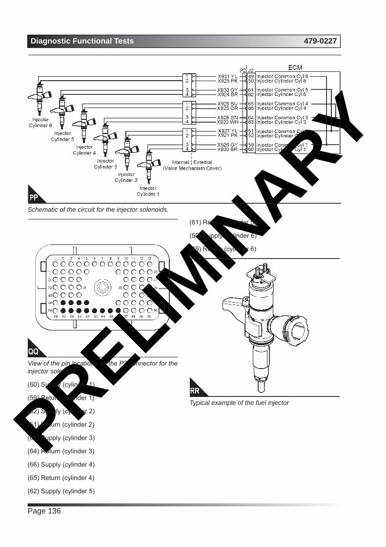
PRELIMIN
ARYDiagnostic Functional Tests 479-0227
Page 136
Schematic of the circuit for the injector solenoids.
View of the pin locations on the P2 connector for the injector solenoids
(60) Supply (cylinder 1)
(59) Return (cylinder 1)
(52) Supply (cylinder 2)
(51) Return (cylinder 2)
(63) Supply (cylinder 3)
(64) Return (cylinder 3)
(66) Supply (cylinder 4)
(65) Return (cylinder 4)
(62) Supply (cylinder 5)
(61) Return (cylinder 5)
(50) Supply (cylinder 6)
(49) Return (cylinder 6)
Typical example of the fuel injector

PRELIMIN
ARY479-0227 Diagnostic Functional Tests
Page 137
Example of the harness connector for the fuel injectors.
Typical example of the connector in the cylinder head
Test Step 1. Inspect Electrical Connectors and Wiring
WARNING
Electrical Shock Hazard. The electronic unit injectors use DC voltage. The ECM sends this voltage to the electronic unit injectors. Do not come in contact with the harness connector for the electronic unit injectors while the engine is operating. Failure to follow this instruction could result in personal injury or death.
1. Turn the keyswitch to the OFF position. A strong electrical shock hazard is present if the keyswitch is not turned OFF.
2. Thoroughly inspect the connectors at the cylinder head. Refer to Troubleshooting, “Electrical Connectors - Inspect” for details.
3. Perform a 45 N (10 lb) pull test on each of the wires in the ECM connector that are associated with injector solenoids.
4. Check the screw for the ECM connector for the correct torque of 6 N·m (53 lb in).
5. Check the harness and wiring for abrasion and for pinch points from the injectors to the ECM.
Results:• All connectors, pins, and sockets are correctly
connected and/or inserted and the harness is free of corrosion, of abrasion and of pinch points. – The harness is OK. Proceed to Test Step 2.
• There is a fault in the connectors and/or the harness.
Repair:Repair the connectors or the harness and/or replace the connectors or the harness. Ensure that all of the seals are correctly in place and ensure that the connectors are correctly connected.
Use the electronic service tool in order to clear all logged diagnostic codes and then verify that the repair eliminates the fault.
Test Step 2. Use the “Injector Solenoid Test”1. Start the engine.
2. Allow the engine to warm up to the normal operating temperature.
3. Stop the engine.
4. Turn the keyswitch to the ON position.
5. Access the “Injector Solenoid Test” by accessing the following display screens in order:
• “Diagnostics”
• “Diagnostic Tests”
• “Injector Solenoid Test”
6. Activate the test.
Note: Do not confuse the “Injector Solenoid Test” with the “Cylinder Cutout Test” . The “Cylinder Cutout Test” is used to shut off fuel to a specific cylinder while the engine is running. The “Injector Solenoid Test” is used to actuate the injector solenoids while the engine is not running.
Results:• All cylinders indicate “OK” – There is not an
electronic fault with the injectors at this time.
Repair: Use the electronic service tool to clear all logged diagnostic codes. Return the engine to service.

PRELIMIN
ARYDiagnostic Functional Tests 479-0227
Page 138
• Not OK - Open – Note the cylinders that indicate “Open” . Proceed to Test Step 3.
• Not OK - Short – Note the cylinders that indicate “Short” . Proceed to Test Step 4.
Test Step 3. Check the Harness between the ECM and the Cylinder Head for an Open Circuit
WARNING
Electrical Shock Hazard. The electronic unit injectors use DC voltage. The ECM sends this voltage to the electronic unit injectors. Do not come in contact with the harness connector for the electronic unit injectors while the engine is operating. Failure to follow this instruction could result in personal injury or death.
1. Turn the keyswitch to the OFF position. A strong electrical shock hazard is present if the keyswitch is not turned OFF.
2. Disconnect the connector for the suspect injector from the cylinder head.
3. Turn the keyswitch to the ON position.
4. Fabricate a jumper wire 100 mm (4 inch) long with terminals on both ends of the wire.
5. Insert one end of the jumper wire into the terminal for the supply to the suspect injector. Insert the other end of the jumper wire into the terminal for the return circuit for the suspect injector.
6. Perform the “Injector Solenoid Test” at least two times.
7. Repeat this test for each suspect injector. Stop the “Injector Solenoid Test” before handling the jumper wires.
Results:• The electronic service tool displays “Current
Above Normal” for the cylinder with the jumper wire. – The harness between the ECM and the cylinder head is OK. The ECM is OK. Proceed to Test Step 5.
• The electronic service tool does not display “Current Above Normal” for the cylinder with the jumper wire. – There is a fault between the ECM and the cylinder head. Proceed to Test Step 6.
Test Step 4. Check the Harness between the ECM and the Cylinder Head for a Short Circuit
WARNING
Electrical Shock Hazard. The electronic unit injectors use DC voltage. The ECM sends this voltage to the electronic unit injectors. Do not come in contact with the harness connector for the electronic unit injectors while the engine is operating. Failure to follow this instruction could result in personal injury or death.
1. Turn the keyswitch to the OFF position. A strong electrical shock hazard is present if the keyswitch is not turned OFF.
2. Disconnect the connector for the suspect injector from the cylinder head.
Note: Cylinder 1 and cylinder 2 share the same connector. Cylinder 3 and cylinder 4 share the same connector. Cylinder 5 and cylinder 6 share the same connector.
3. Turn the keyswitch to the ON position.
4. Perform the “Injector Solenoid Test” at least two times.
5. Repeat this test for each suspect injector. Stop the “Injector Solenoid Test” before handling the jumper wires.
Results:• The electronic service tool displays “Current
Below Normal” for the suspect cylinder and the cylinder that shares the same connector. – The harness between the ECM and the cylinder head is OK. The ECM is OK. Proceed to Test Step 5.
• The electronic service tool does not display “Current Below Normal” for the suspect cylinder Proceed to Test Step 6.
Test Step 5. Exchange the Injector Harness Under the Valve Mechanism Cover
WARNING
Electrical Shock Hazard. The electronic unit injectors use DC voltage. The ECM sends this voltage to the electronic unit injectors. Do not come in contact with the harness connector for the electronic unit injectors while the engine is operating. Failure to follow this instruction could result in personal injury or death.
1. Turn the keyswitch to the OFF position. A strong
PRELIMIN
ARY479-0227 Diagnostic Functional Tests
Page 139
electrical shock hazard is present if the keyswitch is not turned OFF.
2. Remove the valve mechanism cover. Refer to Disassembly and Assembly, “Valve Mechanism Cover - Remove and Install” for the correct procedure.
3. Disconnect the connector for the suspect injector from the cylinder head. Disconnect the connector from the adjacent pair of injectors.
4. Exchange the two internal harnesses. Refer to Disassembly and Assembly, “Electronic Unit Injector - Remove” and refer to Disassembly and Assembly, “Electronic Unit Injector - Install” for the correct procedure.
5. Perform the “Injector Solenoid Test” at least two times.
Results:• Exchanging the harnesses causes the fault to
move to another injector – There is a fault with the suspect injector harness under the valve mechanism cover.
Repair:Repair the suspect injector harness or replace the suspect injector harness under the valve mechanism cover.
Use the electronic service tool in order to clear all logged diagnostic codes and then verify that the repair eliminates the fault.
• The fault remains on the same injector when the harness is exchanged – The injector may be faulty.
Repair: Replace the faulty injector. Refer to Disassembly and Assembly, “Electronic Unit Injector - Remove” and Disassembly and Assembly, “Electronic Unit Injector - Install”.
Perform the “Injector Solenoid Test”.
Use the electronic service tool to clear all logged diagnostic codes and verify that the repair eliminates the fault.
Test Step 6. Bypass the Wiring Between the ECM and the Cylinder Head
WARNING
Electrical Shock Hazard. The electronic unit injectors use DC voltage. The ECM sends this voltage to the electronic unit injectors. Do not come in contact with the harness connector for the electronic unit injectors while the engine is operating. Failure to follow this instruction could result in personal injury or death.
1. Turn the keyswitch to the OFF position. A strong electrical shock hazard is present if the keyswitch is not turned OFF.
2. Disconnect connector P2 from the ECM.
3. Thoroughly inspect the P2 connector. Refer to Troubleshooting, “Electrical Connectors - Inspect”.
4. Disconnect the connector for the suspect injector from the cylinder head.
5. Remove the supply wire and the return wire for the suspect injector from the P2 connector. Remove the supply wire and the return wire for the suspect injector from the connector on the engine harness.
6. Fabricate two jumper wires that are long enough to reach from the ECM to the connector for the suspect injector.
7. Insert one end of a jumper wire into the terminal for the supply to the suspect injector on the P2 connector. Insert the other end of the jumper wire into the terminal on the connector for the supply to the suspect injector.
8. Insert one end of the other jumper wire into the return terminal for the suspect injector on the P2 connector. Insert the other end of the jumper wire into the return terminal on the connector for the suspect injector.
9. Reinstall the P2 connector to the ECM.
10. Reconnect the connector for the suspect injector to the cylinder head.
11. Turn the keyswitch to the ON position.
12. Perform the “Injector Solenoid Test” at least two times.
Results:• The fault disappears with the jumper wire

PRELIMIN
ARYDiagnostic Functional Tests 479-0227
Page 140
installed – The fault is in the engine harness.
Repair:Repair the faulty harness or replace the faulty harness.
Use the electronic service tool in order to clear all logged diagnostic codes and then verify that the repair eliminates the fault.
• The fault is still present with the jumper wire installed – There may be a fault with the ECM.
Repair: Perform the following repair:
1. Make sure that the latest flash file for the application is installed in the ECM. Refer to Troubleshooting, “Flash Programming”.
2. Contact Perkins Global technical Support.
Note: This consultation can greatly reduce the repair time.
3. If Perkins Global technical Support recommend the use of a test ECM, install a test ECM. Refer to Troubleshooting, “Replacing the ECM”.
4. Remove the jumper wires and return all wires to the original configuration.
5. Perform the “Injector Solenoid Test” .
6. If the fault is eliminated with the test ECM, reconnect the suspect ECM.
7. If the fault returns with the suspect ECM, replace the ECM.
8. Use the electronic service tool in order to clear all logged diagnostic codes and then verify that the repair eliminates the fault.
Solenoid Valve - TestSystem Operation Description:This procedure covers the following codes:
Diagnostic Trouble Codes for the Solenoid ValvesJ1939 Code
Description Notes
1076-5 Engine Fuel Injection Pump Fuel Control Valve : Current
Below Normal
The Electronic Control Module (ECM) detects the following conditions:Low current in the output from the ECM to the suction control valve solenoid on the high-
pressure fuel pump for 0.6 seconds.There are no active 168 diagnostic codes.
The ECM has been powered for at least 0.25 seconds.If equipped, the warning lamp will come on. The ECM will log the diagnostic code.
This diagnostic code indicates a fault in the circuit for the suction control valve solenoid.
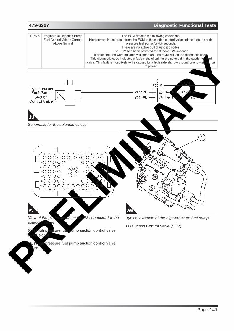
PRELIMIN
ARY479-0227 Diagnostic Functional Tests
Page 141
1076-6 Engine Fuel Injection Pump Fuel Control Valve : Current
Above Normal
The ECM detects the following conditions:High current in the output from the ECM to the suction control valve solenoid on the high-
pressure fuel pump for 0.6 seconds.There are no active 168 diagnostic codes.
The ECM has been powered for at least 0.25 seconds.If equipped, the warning lamp will come on. The ECM will log the diagnostic code.
This diagnostic code indicates a fault in the circuit for the solenoid in the suction control valve. This fault is most likely to be caused by a high side short to ground or a low side short
to power.
Schematic for the solenoid valves
View of the pin locations on the P2 connector for the solenoid valves
(69) High pressure fuel pump suction control valve PWM signal
(70) High pressure fuel pump suction control valve return.
Typical example of the high-pressure fuel pump
(1) Suction Control Valve (SCV)

PRELIMIN
ARYDiagnostic Functional Tests 479-0227
Page 142

PRELIMIN
ARYCalifornia
Proposition 65 Warning
Diesel engine exhaust and some of its constituents are known to the State of California to cause cancer, birth
defects, and other reproductive harm.

PRELIMIN
ARY
All information in this document is substantially correct at time of printing and may be altered subsequently. Part No. 479-0227 issue 1Produced in England ©2016
22 Cobham Road, Ferndown Industrial Estate, Wimborne, Dorset, BH21 7PW, England.Tel: +44 (0)1202 796000, Fax: +44 (0)1202 796001E-mail: [email protected]
Web: www.perkins.com/Marine