![Preparation of multiwall carbon nanotubes (MWCNTs ...€¦ · polymeric reinforcement[1–4].Theypossessoutstandingelec-trical, mechanical and thermal properties compared to conven-tional](https://static.fdocuments.in/doc/165x107/5f0d06527e708231d4384d8d/preparation-of-multiwall-carbon-nanotubes-mwcnts-polymeric-reinforcement1a4theypossessoutstandingelec-trical.jpg)
Part II Carbon Nanotubes - UAH - Engineering II Carbon Nanotu… · Multiwall Carbon...
16
Spring 2009 EE 710: Nanoscience and Engineering Part 2: Carbon Nanotubes Images and figures supplied from Bhushan, Springer Handbook of Nanotechnology 2 nd ed., Springer, 2007 Ch 3b M hi l Chapter 3, by Monthioux, et.al. Instructor: John D. Williams, Ph.D. Assistant Professor of Electrical and Computer Engineering A it Di t f th N d Mi D i C t Associate Director of the Nano and Micro Devices Center University of Alabama in Huntsville 406 Optics Building Huntsville, AL 35899 Ph (256) 824 2898 Phone: (256) 824-2898 Fax: (256) 824-2898 email: [email protected] 1
-
Upload
duongkhanh -
Category
Documents
-
view
219 -
download
1
Transcript of Part II Carbon Nanotubes - UAH - Engineering II Carbon Nanotu… · Multiwall Carbon...

Spring 2009 EE 710: Nanoscience and Engineering
Part 2: Carbon NanotubesImages and figures supplied from
Bhushan, Springer Handbook of Nanotechnology 2nd ed., Springer, 2007Ch 3 b M hi lChapter 3, by Monthioux, et.al.
Instructor: John D. Williams, Ph.D.Assistant Professor of Electrical and Computer Engineering
A i t Di t f th N d Mi D i C tAssociate Director of the Nano and Micro Devices CenterUniversity of Alabama in Huntsville
406 Optics BuildingHuntsville, AL 35899Ph (256) 824 2898Phone: (256) 824-2898
Fax: (256) 824-2898email: [email protected] 1

What is a Single Wall Carbon N b (SWNT)Nanotube (SWNT)
• Imagine a graphene sheet rolled up and bonded end to end on one sideside.
• Then seal the ends of the tube with half sections of a fullerene sized to the diameter of the cylinder
• All carbon nanotubes involve a hexagonal aromatic ringsAll t i i l t iti t t th d h t l– All atoms are in equivalent positions except at the ends where pentagonal rings are required.
– Binding sites for a carbon nanotube are preferentially defined at the ends of the tube on the pentagonal ring.
• sp3 binding of curved hexagonal rings:sp binding of curved hexagonal rings:– make nanotubes more reactive planar graphene – overlapping energy bands that result in versatile electronic behavior
• Tube diameters for carbon nanotubes: d = 0 4 nm is smallest synthesized due to high stresses and energy– d = 0.4 nm is smallest synthesized due to high stresses and energy required to maintain bonds
– d > 2.5 nm is not energetically favorable over graphene and only a few carbon nanotubes with larger diameters have been reported
– d = 1.4 nm is most common observed• Tube length restrictions: only the preparation method
2
JDW, UAHuntsville ECE, Spring 2009

• Multiple ways to roll graphene into a tubeS t b b d t l• Some tubes are bound on symmetry planes
• Others have a helical or chiral nature.– Vector of helicity, Ch, ⊥ to tube axis– the angle of helicity,θ
aa
yaxaa
amanCOA h
3
ˆ2
ˆ2
3ˆ
ˆˆ
1
21
+=
+==
a=2.46 Ang
– Diameter, D, is related to Ch bynmmn
mn
yaxaa
22cos
ˆ2
ˆ2
3ˆ
22
2
++
+=
−=
θ (0,0), , h y
( )
AngaAng
nmmnaChD
cc
cc
44.141.1
3 22
≤≤
++==
ππ
graphite C
(n,n)
graphite C60
Thus we nave (n,m) nanotubes as a description of their helicity
(n,m)3
JDW, UAHuntsville ECE, Spring 2009
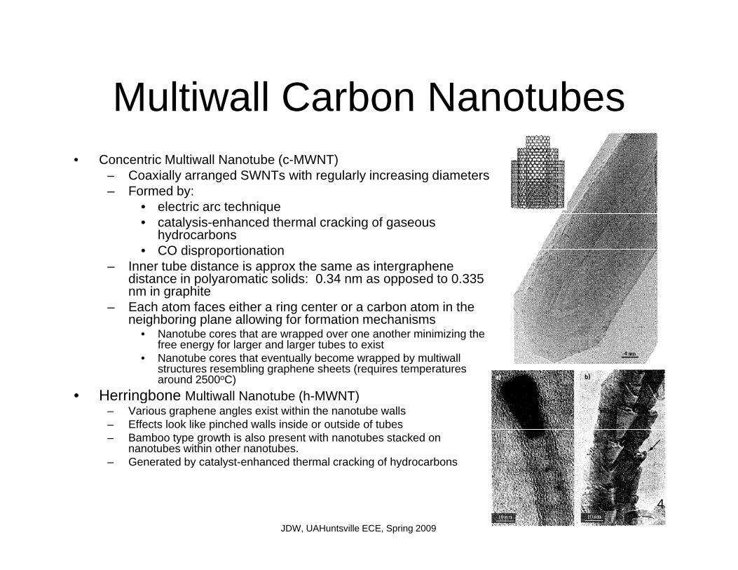
Multiwall Carbon NanotubesMultiwall Carbon Nanotubes• Concentric Multiwall Nanotube (c-MWNT)
– Coaxially arranged SWNTs with regularly increasing diametersCoaxially arranged SWNTs with regularly increasing diameters– Formed by:
• electric arc technique• catalysis-enhanced thermal cracking of gaseous
hydrocarbons• CO disproportionation• CO disproportionation
– Inner tube distance is approx the same as intergraphene distance in polyaromatic solids: 0.34 nm as opposed to 0.335 nm in graphite
– Each atom faces either a ring center or a carbon atom in the neighboring plane allowing for formation mechanismsneighboring plane allowing for formation mechanisms
• Nanotube cores that are wrapped over one another minimizing the free energy for larger and larger tubes to exist
• Nanotube cores that eventually become wrapped by multiwall structures resembling graphene sheets (requires temperatures around 2500oC)
Herringbone M lti ll N t b (h MWNT)• Herringbone Multiwall Nanotube (h-MWNT)– Various graphene angles exist within the nanotube walls – Effects look like pinched walls inside or outside of tubes– Bamboo type growth is also present with nanotubes stacked on
nanotubes within other nanotubes.– Generated by catalyst-enhanced thermal cracking of hydrocarbonsGenerated by catalyst enhanced thermal cracking of hydrocarbons
4
JDW, UAHuntsville ECE, Spring 2009

CNT Synthesis with Solid CarbonCNT Synthesis with Solid Carbon• Solid carbon source
– Laser ablation, Solar energy, dc electric arc, three-phase ac arc plasmathree phase ac arc plasma
– All have temp between 1000 and 6000K– All processes generate SWNT from a solid
graphite source• Electric arc technique method is the principleElectric arc technique method is the principle
method for generating fullerenes in large quantity– Requires high temp, absence of oxygen,
presence of carbon atoms– For nanotubes, a catalyst on either the , y
electrode or the target is required• Ni/Co, Ni/Y, Ni/Ce
– Arcs generated on diamond have increased SWNT yields over MWNT yields by 230%
• New considerations for thermal heat transfer, and homogeneity of the source are therefore being examined
5
JDW, UAHuntsville ECE, Spring 2009

CNT Synthesis with Solid Carbon• Basic principle of all methods
– Energy transfer from the radiation (or plasma) source to the material causes i l di t th f ti f l
CNT Synthesis with Solid Carbon
erosion leading to the formation of a plasma. – Degree of ionization in the plasma, n=ne/(ne+no), its chemical composition,
the bias of the deposition plate, and the temperature of the dep. plate regulate the deposition quality of the SWNT
– Advantages: lots of knobs to turn that allow for the production of different types of SWNTs
– Disadvantages: Nanotubes are not pure. They are deposited with other carbon phases and remnants of the catalyst.carbon phases and remnants of the catalyst.
• All currently proposed purification methods are acid-based oxidation processes that are likely to significantly affect the SWNT structure. Subsequent thermal treatments around 1200oC however are successful in recovering some structural qualityquality.
6
JDW, UAHuntsville ECE, Spring 2009

Gaseous Based CNT ProductionGaseous Based CNT Production• Catalytic Chemical Vapor Deposition (CCVD):
catalysis-enhanced thermal crackingcatalysis enhanced thermal cracking– Catalytic decomposition of carbon-containing source
on small metallic particles or clusters– Metals used: Fe, Co, Ni– 600 – 1000oC process– Better for production of MWNTBetter for production of MWNT– NT are generally much longer than those generated
by arc discharge processes– Possible to grow dense arrays of nanotubes using this
technique– Process is subject to structural defectsj– SWNTs generated typically have smaller diameters
than those by other methods and are produced in bundles
• Heterogeneous Processes– Passing of gaseous low mol weight hydrocarbons
over a cat bed of metal particles in a furnace.– Particles are deposited onto the substrate by spraying
a suspension of the metal particles onto it or by having said particles imbedded on a substrate of alumina, zeolite, mag. Oxide etc.
7
JDW, UAHuntsville ECE, Spring 2009

Gaseous Based CNT ProductionGaseous Based CNT Production• Homogeneous Processes
– Decompose a carbon source (benzene etc.)
– Decompose metal organic compound at the same time onto a substrate forming initiation nanoparticle and atomicinitiation nanoparticle and atomic initiation sites
• Templating– No catalyst used. Nanotubes are grown
directly in porous substrates of aluminadirectly in porous substrates of alumina or zeolite. Subsequent etching of the porous media results in tubes of a constrained size and length
8
JDW, UAHuntsville ECE, Spring 2009

Synthesis with Controlled O i iOrientation
• Several applications require nanotubes to be grown in highlynanotubes to be grown in highly aligned bundles
• Want highly controlled growth, purity, texture, and structure
• CCVD on patterned catalysts are the• CCVD on patterned catalysts are the more promising methods for these requirements
• Alignment of NTs during growth is due to van der Walls interactionsdue to van der Walls interactions which promote ⊥ growth from the substrate
• Patterning into mesoporous substrates affects the alignment and ggrowth direction of NTs.
– Thus porosity control and vertically of mesoporous substrates must be considered.S l t l ti t h i– Several templating techniques can be used as long as there is a high temperature resistant mask with a metal seed at the base 9
JDW, UAHuntsville ECE, Spring 2009

Growth Mechanisms for CNTsGrowth Mechanisms for CNTs• Actual growth mechanisms of CNTs are still under debate
C t F G th• Cat-Free Growth– Driving force for growth is related to the elctric field – It is not clear how the MENT nucleus is formed but once it has, it appears to direct the primary
graphene structure for further growthD t t th id th t C i d di tl b ti it d i f ti– Data supports the idea that C2 species are consumed directly by active sites during formation to grow the nanotube two carbons at a time.
• Cat-Activated Growth– Low temperature
CCVD 1000 C• CCVD 1000oC• Adsorption and decomposition of C- containing gaseous species• Followed by dissolution then diffusion of c- species through the catalyst forming a solid
solutionN t b k i it ti f th lid b t b ll• Next back –precipitation of the solid carbon as nanotube walls
• Texture is defined by the orientation of crystal faces relative to the filament axis• Tip growth can occur two ways
– Catalyst will move forward up the tip of the structure reacting with the C-species and precipitating nanotube walls in its wakenanotube walls in its wake
– Alternatively on the surface, small nanoparticles of cat are held in place by interaction with the substrate forcing the formation of nanotube walls to occur and the surface as the tube is grown from the bottom up 10
JDW, UAHuntsville ECE, Spring 2009

Not allowed
Top down Bottom upp p
11
JDW, UAHuntsville ECE, Spring 2009

High Temp Cat Processes using Solid source methods
– Pentagonal C deposited on a catylst activates local C2 groups to form crystalline symmetry
– Excess C2 during the formation process leads to preferential formation of CNTs over Fullerenes
– Capping and merging of nanotubes occurs when thermal gradients are decreased leading to the reduction of C chemical potential withare decreased, leading to the reduction of C2 chemical potential with respect to that required to bind with larger molecules and close the structure completely
From Electric Arc Experiments on Graphite 12
JDW, UAHuntsville ECE, Spring 2009
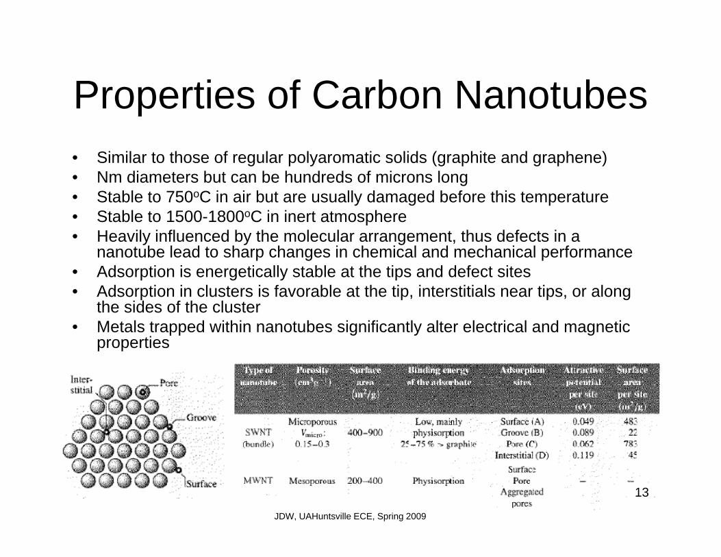
Properties of Carbon NanotubesProperties of Carbon Nanotubes• Similar to those of regular polyaromatic solids (graphite and graphene)
N di t b t b h d d f i l• Nm diameters but can be hundreds of microns long• Stable to 750oC in air but are usually damaged before this temperature• Stable to 1500-1800oC in inert atmosphere• Heavily influenced by the molecular arrangement, thus defects in a y y g ,
nanotube lead to sharp changes in chemical and mechanical performance• Adsorption is energetically stable at the tips and defect sites• Adsorption in clusters is favorable at the tip, interstitials near tips, or along
the sides of the cluster• Metals trapped within nanotubes significantly alter electrical and magnetic
properties
13
JDW, UAHuntsville ECE, Spring 2009

Electronic PropertiesElectronic Properties• Electronic structure similar to graphene without the magnetic spin
order effect observed at graphene edgesorder effect observed at graphene edges• Small Diameter SWNTs with (0,0) or (n,n) are semiconductors• Helical (n,m) tubes are typically conductors• MWNTs and large diameter tubes are metallic conductorsMWNTs and large diameter tubes are metallic conductors• Photoluminescence is also present in SWNTs but not in MWNTs• Ballistic conductance similar to that of graphene is predicted in
MWMTs with a QM limited conductance• Exhibit positive or negative magnetoresistance depending on
current, temperature, field, SWNT, or MWNT etc.
14
JDW, UAHuntsville ECE, Spring 2009

Mechanical PropertiesMechanical Properties• Unique due to the particular strong bonding between carbons which is
stronger than diamondstronger than diamond – Graphene bond length 1.42 Ang– Diambond bond length 1.54 Ang
• Makes SWNTs and MWNTs particularly stable against deofmraitons• Tensile strength of SWNT is 20 times that of steel at 45 GPa• Tensile strength of MWNTs have been measured at 150 GPa• Flexible modulus of MWNTs is thought to be higher than SWNT for obvious
reasons however measurements show MWNTs have 3-30 GPa and SWNTs have been reported as 1 TPa
15
JDW, UAHuntsville ECE, Spring 2009

CNT based ObjectsCNT based Objects• Heteronanotubes
Nanotubes with some or all of the carbons replaced with– Nanotubes with some or all of the carbons replaced with other atoms such as Boron or Nitrogen
– BN tubes are electrical insulators– C-MWNTs coax materials with altnernating C and BN
tubes have been demonstrated• Hybrid carbon nanotubes are cavity filled with foreign• Hybrid carbon nanotubes are cavity filled with foreign
atoms or molecules (X@SWNT)– Allows the study of confined nanotstructures– Filling nanotubes during growth is one of the pioneering
methods of nanotechnologyM t i l t d iti fill i– Most cases involve post deposition fills using
• Wet chemistry based on capillarity• Diffusion of a molten material• Sublimation of a gaseous matrial
– Filing rates are difficult to estimateTh f t th t t b th d i t b dl l
Molten Diffusion of PbI@2WMT in liquid form at P=100-200 N/m2
– The fact that nanotubes are gathered into bundles also increases the difficulty in estimating the number of filled tubes
– X-ray and Raman spectroscopy are used to determine fillsAlso precursors can be used to fill tubes with materials– Also, precursors can be used to fill tubes with materials not previously though possible
Sublimation of C60@SWNT at 250oC followed by 1200oC Aneal
16
JDW, UAHuntsville ECE, Spring 2009