
Part II - CAD and Reverse Engineering€¦ · File formats for data exchange. Exercises. Reverse...
36
DRAFT VERSION - Francesca Campana "Advanced method In mechanical Design" - lecture notes vers0 Part II - CAD and Reverse Engineering CAD systems. Product Data Management, Product Lifecycle management. Solid and surface modeling. New and advanced CAD approaches. Shape design and system arrangement: general criteria and methods. File formats for data exchange. Exercises. Reverse Engineering: acquisition methods, post-processing, examples and exercises. Part II - CAD and Reverse Engineering 1.1 CAD systems: introduction and approaches. 1.2 Product Data Management / Product Lifecycle Management 1.3 Solid modeling – advanced use and functions of the featured-based design 1.4 Surface Modeling and shape design 1.5 Strategies for system design 1.6 File formats for data exchange 1.7 Reverse Engineering techniques in industrial engineering 1.7.1 Research topics in Reverse Engineering 1.8 Reverse Engineering: acquisition methods 1.8.1 Non- contact methods 1.8.2 Contact methods 1.8.3 System performance and hardware selection 1.9 Reverse Engineering: post-processing 1.10 Reverse Engineering: case studies and applications 1.11 Exercises References
Transcript of Part II - CAD and Reverse Engineering€¦ · File formats for data exchange. Exercises. Reverse...

DRAFT VERSION - Francesca Campana "Advanced method In mechanical Design" -
lecture notes vers0
Part II - CAD and Reverse Engineering
CAD systems. Product Data Management, Product Lifecycle management. Solid and
surface modeling. New and advanced CAD approaches. Shape design and system
arrangement: general criteria and methods. File formats for data exchange. Exercises.
Reverse Engineering: acquisition methods, post-processing, examples and exercises.
Part II - CAD and Reverse Engineering
1.1 CAD systems: introduction and approaches.
1.2 Product Data Management / Product Lifecycle Management
1.3 Solid modeling – advanced use and functions of the featured-based design
1.4 Surface Modeling and shape design
1.5 Strategies for system design
1.6 File formats for data exchange
1.7 Reverse Engineering techniques in industrial engineering
1.7.1 Research topics in Reverse Engineering
1.8 Reverse Engineering: acquisition methods
1.8.1 Non- contact methods
1.8.2 Contact methods
1.8.3 System performance and hardware selection
1.9 Reverse Engineering: post-processing
1.10 Reverse Engineering: case studies and applications
1.11 Exercises
References

DRAFT VERSION - Francesca Campana "Advanced method In mechanical Design" -
lecture notes vers0
Part II - CAD and Reverse Engineering
CAD systems. Product Data Management, Product Lifecycle management. Solid and
surface modeling. New and advanced CAD approaches. Shape design and system
arrangement: general criteria and methods. File formats for data exchange. Exercises.
Reverse Engineering: acquisition methods, post-processing, examples and exercises.
1.1 CAD systems: introduction and approaches.
CAD stands for Computer Aided Design and it is part of the Information Technology (IT)
resources of a Company, representing the most important tool to develop, optimize and
manage products. It concerns with a set of commercial software applications (e.g. Solid
Edge, Catia, Solid works, Creo, Inventor, ...) able to attend many steps involved in
component and assembly design, report and optimization. It is divided into
environments, each of them specifically designed for a design purpose. Three
environments are the core: (a) component's solid modeling, (a) assembling and (b)
drafting. Other environments can exist according to specific tasks like welding, sheet
metal design, surface design, injection molding, ergonomics, ...
Generally speaking, environments are divided into general purpose and vertical
applications. These last ones are devoted to applications oriented to a specific design
branch (sheet metal design, welding, ...), the other ones can be applied to each kind of
mechanical component or assembly (e.g. solid modeling, assembling, drafting, surface
modeling, ....).
CAD systems development and success is related to computer progress since they
represent one of the most relevant examples of IT application. They benefit from
hardware improvements, software architecture design and database management since
they work according to:
- a core library of geometric modeling algorithms also known as "geometric modeling
kernel" (e.g. Parasolid, Acis, OpenCascade, and so on - some of them are proprietary
kernel, other ones are not)
- a set of input-output hardware devices able to accomplish the user interactions
(keyborad, mouse, screen, joystick, graphics tablet, generally speaking everything is part
of man-machine interface: e.g. virtual reality)

DRAFT VERSION - Francesca Campana "Advanced method In mechanical Design" -
lecture notes vers0
- hardware for computation and processing in particular they ask for a good
performance of graphics card, CPU and RAM
Thus the expertise behind their development is multidisciplinary and involves electronics
(to provide the hardware), informatics (to provide GUI and software architecture),
computational geometry (to provide the computational kernel) and mechanical
engineering knowledge definition (to gather the requirements necessary to its use).
Solid modeling represents the central part of CAD. It is devoted to build a 3D model of a
component that can be:
- graphically manipulated continuously and from any angle;
- exported and link to the other environment to be processed according to the different
necessity of the design workflow (simulation, manufacturing, technical drawing, data
archiving, ...).
A solid model can be defined according to three approaches: (a) feature-based design;
(b) explicit modeling; (c) free-form and surface modeling. Nowadays integration of them
is one of the design trends. Explicit modeling does not require the tree archive of the
modeling work (history tree), on the contrary feature-based design is strongly connected
to the historical hierarchy of modeling steps as defined in the history tree. Feature-
based design is fully parametric and it is able to pursue and show the design intent,
explicit modeling does not, since the 2D profile necessary to achieve it becomes hide
object after the volume definition. Doing so model changes must be provided working
directly on the solid model (by cutting, copying, protruding), not by the parametric
changes. Advantages of the explicit modeling are mainly the reduction of memory
necessary to manage the model and minor requirements of a pre-defined modeling
strategy. In other words it can be said that explicit modeling overcomes the concept of
feature (although it can be used a basic function to add/remove volume) to be focused
directly to the 3D shape that must be achieved, no matter if it is obtained by recursively
adding/subtracting volumes in the same domain. It is something more similar to
sculpturing. This makes this approach relevant for conceptual design and preliminary
lay-out since in these steps component's topology1 and shape (section, thickness) are
1 An extended definition of topology will be provided in next sections. Now consider that in mathematics, concerns with the properties of space that are preserved under continuous deformations that do not tear the
DRAFT VERSION - Francesca Campana "Advanced method In mechanical Design" -
lecture notes vers0
not completely defined.
Surface modeling (or free-form modeling) concerns with the capability of modeling
complex surface according to NURBS (Non Uniform Rational B-Splines) algorithms. It
enlarges shape modeling capability and it also represents the mathematical starting
point to develop an explicit modeling approach. This demonstrates the link among the
three strategies and the capability of mixing them together to improve design work.
1.2 Product Data Management / Product Lifecycle Management
CAD systems are part of a larger set of software applied in product development and
management. More in details there are many Computer Aided tools, also known as CAx
technologies, wher "x" stands for a specific branch of the product development. "x" can
be "manufacturing" (CAM system), "production planning" (CAPP), "engineering" (CAE),
... All of them apply IT technologies to a specific step of the design process, aiding the
engineering to reduce time to market and look for product optimization as soon as
possible.
Obviously all these software provide data and files necessary to report and qualify the
work. These data together with other documents (e.g. list of requirements, design
review reports, query of previous designs,....) are archived into specific database that
should be managed by the so-called Enterprise Resource Planning (ERP)2. SAP is one of
the most well-established software. It is used to manage all the data concerning the
business activities of a product. A Product Data Management System (PDM) is a
software solution able to provide the integration among CAx tools and ERP, or in some
case to define a sort of ERP for the design activities. If it is focused on the product
development, it can also be defined as a Product Lifecycle Management tool (PLM).
Exercises
1. Please explain the meaning of Information Technology and provide all the types of
hardware and software useful for the product lifecycle assessment and development.
2. Which is the name of the CAD system you have already applied? How many
environments has it? Can you describes their aims?
volume/surface/line 2 Be careful the level of integration is related to the type of Enterprise. Bigger it is, higher the integration is.

DRAFT VERSION - Francesca Campana "Advanced method In mechanical Design" -
lecture notes vers0
1.3 Solid modeling – advanced use and functions of the featured-based design
Solid modeling represents the core of a CAD system oriented to industrial engineering applications. Its main goal is to provide 3D shapes for a digital mock-up of components and systems. Nowadays it implements more than one approach among that have been developed and used positively in the past together with new development (wireframe, feature-based, explicit approach, curve modeling, ….)3. Considering the design workflow, the drawing activities can be divided as follows: Sketch design that is made by graphs, schematic symbols coupled with mono/bi-dimensional drawing. Conceptual design that is as a detailed version of the sketch including more features provided by technical experience, that must be verified and optimized by subsequent computations according system design and performances. Detailed design that provides details of each component starting from the conceptual design and then including optimization procedures based on the list of requirements. Detailed/Executive design that includes also information about manufacturing requirements and constraints.
2D drawing tools
Feature-based design
Explicit design Computer Aided Drafting
Sketch xxx
Concept xx xx
Detailed drawing
xxx xx
Executive drawing
xxx xxx
Usually, CAD models start to be defined at the end of the conceptual step and, if they are not thought to be made by additive manufacturing, feature-based design is one of the most suitable approach to determine them. It is due to the fact that this approach is relevant in case of: components made by manufacturing technologies related to features (such as protrusion based components, pocket or thin shapes made by sheet metal or injection molding, machined parts, … components defined according to standards that can be used in many designs after minor revisions (such as length updating or local feature suppression) Major properties of this approach are: ordered sequence of work that determines parent-children link among features (top-down=father-son). Changes on the top causes changes down. Sometimes errors can be derived if father details are deleted, but if the work is planned before modeling, parametric design can lead to component templates suitable for a recursive use. This advantage derives from: (a) using geometric constrains to fix section topology of the feature; (b) using lengths as explicit variables than can be change as parameters; (c) anchoring feature extension to geometric entities, as surface, by means of “from…to…” or by “pass through all”. Among advanced uses of the feature-based approach two relevant modes are: parametric design by means of variables and formulas and definition of families of components.
3 For major details about CAD history and basis, please refer to: Kunwoo Lee, “Principles of CAD/CAM/CAE”, Pearson, 1999

DRAFT VERSION - Francesca Campana "Advanced method In mechanical Design" -
lecture notes vers0
Parametric design by formulas allow to define automatic variation of shapes and sizes through formulas implemented by tables embedded in the system or by importing data sheets. A family of components determines a set of variants different according to lengths and/or local features that can be suppressed or activated. By a command table the operator define the master component and determines which variables (lengths or features) represent the variant parameters. Then the family is automatically populated in the directory according to specific combinations of the variable’s values.
Exercises
1. Do you know the basic functionalities of a solid modeling environment based on
featured-design approach? Can you explain the role of the “tree structure” of a
model?
2. In your favorite CAD system look for the design table definition and try to model via
formulas the problem of figure 14 after a proper concept design of the beam
sections.
Fig. 14 – design problem for exercise 3
Suggestions for the solution:
- for the concept design apply rules (a) and (b) discussed in the previous section (in
particular look for uniform stress in bending condition of a truss)-see fig. 15
DRAFT VERSION - Francesca Campana "Advanced method In mechanical Design" -
lecture notes vers0
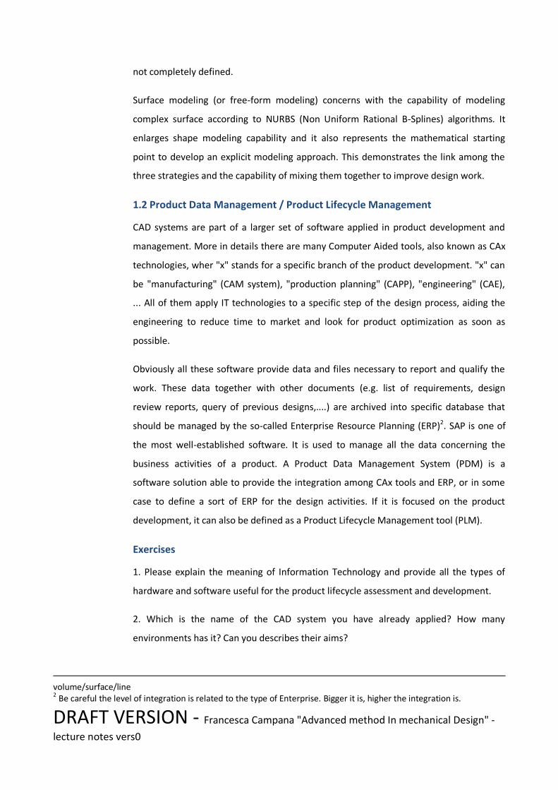
Fig. 15 Concept design
- for sizing and parametric design, choose a material (e.g. steel with limit yield stress
280 MPa) and set up in excel formulas for finding the most stressed sections. After
this define an ordered feature-based model of the components able to implement
the formulas written in excel (fig. 16).
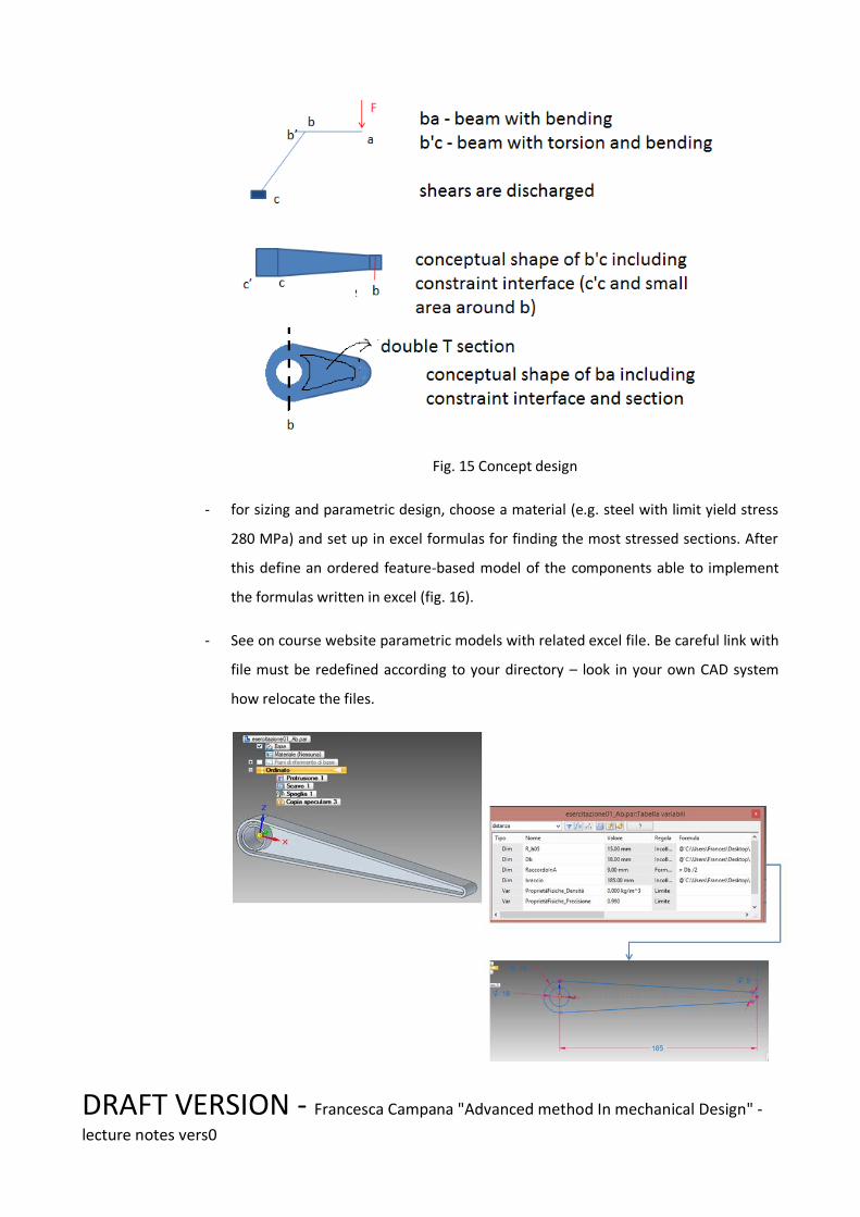
- See on course website parametric models with related excel file. Be careful link with
file must be redefined according to your directory – look in your own CAD system
how relocate the files.

DRAFT VERSION - Francesca Campana "Advanced method In mechanical Design" -
lecture notes vers0
Fig. 16 – Example for the model definition of beam ab
4. In your CAD system look for the definition of a family of parts (design variant definition)

DRAFT VERSION - Francesca Campana "Advanced method In mechanical Design" -
lecture notes vers0
1.4 Surface Modeling and shape design
Surface modeling concerns with free-form shape design as usually request in industrial design or engineering projects that ask for shapes that are not define by means of feature-based operations. Examples of applications are: car-body design, hull design, bio-inspired design. In a classical design workflow artistic sketches, or clay mock-up, makes industrial design shapes, while in CAD environment surface modeling is the approach. It basically consists with operations based on B-Splines or NURBS curves. Complex surfaces may be achieved by network or curves, that defines “patches”, and 1D--->2D operations like protrusion, revolution, sweep of curves along directions, axes, spines, …. Complexity, that means curvatures distribution of the surfaces, is defined by means of the curve shapes, that define the edges of a patch. Continuity in position, tangency and curvature along the edges define the class of a surface. Curvature continuity is the continuity between the surfaces sharing the same boundary. It means that at each point of each surface along the common edge the same radius of curvature is set. In automotive design three classes are defined: - class A accomplishes continuity in position, tangency and curvature with assigned
tolerances - class B releases curvature conditions and define tolerances only for position and
tangency - class C as class B but with lower tolerances. Tolerances are set according to Company requirements (see next table for approximate values).
Table: Surface classes and tolerances
Class A Class B Class C
Position ≤0.01 mm ≤0.01 mm ≤0.05 mm
Tangency ≤0.1° ≤0.1° ≤0.5°
Curvature Same curvature at least along 100 mm of edge
Not relevant Not relevant
Figure 17 gives an example of surface patches for a car-body.

DRAFT VERSION - Francesca Campana "Advanced method In mechanical Design" -
lecture notes vers0
Figure 17 - car-body surface patches
Class A is necessary on surfaces that are visible (e.g. body-in-white, external surfaces of an aesthetic part), class B is necessary for surfaces not always visible (like inner part of bent surfaces), class C is assigned to hide surfaces (loading platforms). 1.4.1 Graphical tools to evaluate shapes To evaluate the quality of a patches CAD environments have specific graphical plots, like curvature analysis and zebra plot. Curvature analysis can been shown in plots as a surface map of min-max radius of curvature (k1 and k2), mean curvature, or gaussian curvature4; or as a graph of curve's curvature (see for example porcupine analysis in CATIA). Fig. 18 gives examples of maps and fig. 19 of porcupine analysis. To perform a consist curvature analysis by maps, patches must have the same orientation of their normal (fig. 20). Maximum curvature (defined as the max(k1,k2)), shows the tightest curvature and checks if it is inside the accepted range. Minimum curvature allows to find flat areas. In case of sheet metal forming they cause flatness problems during stamping. Gaussian curvature shows inflections and saddles of the patch. Mean curvature is interesting to avoid discontinuities in the map when localized saddles occur.
Fig. 18 - Curvature maps5
Fig. 19 - Porcupine analysis6
4 At any point on a surface, we can find a normal vector that is at right angles to the surface; planes containing the normal vector are called normal planes. The intersection of a normal plane and the surface will form a curve called a normal section and the curvature of this curve is the normal curvature. For most points on most surfaces, different normal sections will have different curvatures; the maximum and minimum values of these are called the principal curvatures, call these κ1, κ2. The Gaussian curvature is the product of the two principal curvatures Κ = κ1 κ2. 5 Image taken from Autodesk tutorial aliasworkbench 6 Image taken from Catia help

DRAFT VERSION - Francesca Campana "Advanced method In mechanical Design" -
lecture notes vers0
Fig. 20 - Effect of the surface normal orientation on the curvature analysis7
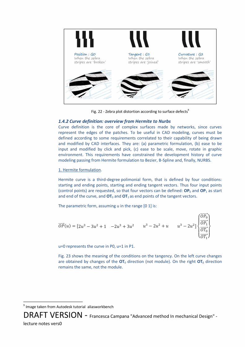
Zebra plot and surface reflection by rendering are other tools for surface evaluation, that simulate the reflection of the surfaces under specific conditions (fig. 21). Surface reflection by rendering uses the reflection to perceive reflectance of the surfaces, thus tangency and curvature. Zebra plots simulate stripe projection on the surface, from a specific angle (horizontal, vertical, any). Surface defects in position, tangency and curvature are shown by means of stripe distortions (fig. 22)
Fig. 21 - Comparison among gaussian curvature analysis (on the left), surface reflection by rendering (center), zebra plot (on the right)
8
7 Image taken from Autodesk tutorial aliasworkbench 8 Images taken from Rhinoceros tutorial
DRAFT VERSION - Francesca Campana "Advanced method In mechanical Design" -
lecture notes vers0
Fig. 22 - Zebra plot distortion according to surface defects9
1.4.2 Curve definition: overview from Hermite to Nurbs Curve definition is the core of complex surfaces made by networks, since curves represent the edges of the patches. To be useful in CAD modeling, curves must be defined according to some requirements correlated to their capability of being drawn and modified by CAD interfaces. They are: (a) parametric formulation, (b) ease to be input and modified by click and pick, (c) ease to be scale, move, rotate in graphic environment. This requirements have constrained the development history of curve modeling passing from Hermite formulation to Bezier, B-Spline and, finally, NURBS.
1. Hermite formulation.
Hermite curve is a third-degree polimonial form, that is defined by four conditions: starting and ending points, starting and ending tangent vectors. Thus four input points (control points) are requested, so that four vectors can be defined: OP0 and OP1 as start and end of the curve, and OT0 and OT1 as end points of the tangent vectors.
The parametric form, assuming u in the range [0 1] is:
u=0 represents the curve in P0, u=1 in P1.
Fig. 23 shows the meaning of the conditions on the tangency. On the left curve changes are obtained by changes of the OT0 direction (not module). On the right OT0 direction remains the same, not the module.
9 Image taken from Autodesk tutorial aliasworkbench

DRAFT VERSION - Francesca Campana "Advanced method In mechanical Design" -
lecture notes vers0
Fig. 23 - Hermite curve changes according to changes of OT0 (direction on the left, module on the right)
Polynomial functions in the parameter u blend the input points according to their shapes.
2. Bezier formulation.
One of the limit of the Hermite formulation is the necessity of split complex curves in a large number of arcs, if complex shape must be defined. Bezier formulation increases the number of control points, up to n, according to this expressions:
Bi,n(u) represents the generic blending function. In case of n=3 (that means 4 control points) they have the shapes shown in fig.24.
Fig. 24 - Belending functions for 4 control points (n=3)
In this case the final curve (called Bezier's curve) passes only for the first and last point of the control points, that define the so-called "curve polygon of control". Fig. 25 shows the meaning of the polygon of control in the case of n=3. It is a convex polygon and it
DRAFT VERSION - Francesca Campana "Advanced method In mechanical Design" -
lecture notes vers0
always contains the curve. Thus operations like roto-translations applied to it are consequently applied to the parametric curve.
Fig. 25 Meaning of curve polygon of control
3. B-Spline formulation.
Main drawbacks of the Bezier are: (a) degree of the curve function of the number of control points (risk of Runge phenomenon); (b) global variation of the shape if only one control point is moved.
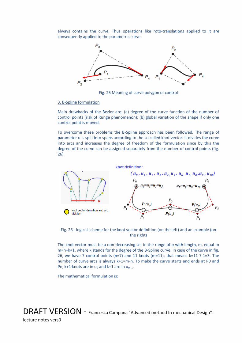
To overcome these problems the B-Spline approach has been followed. The range of parameter u is split into spans according to the so called knot vector. It divides the curve into arcs and increases the degree of freedom of the formulation since by this the degree of the curve can be assigned separately from the number of control points (fig. 26).
Fig. 26 - logical scheme for the knot vector definition (on the left) and an example (on the right)
The knot vector must be a non-decreasing set in the range of u with length, m, equal to m=n+k+1, where k stands for the degree of the B-Spline curve. In case of the curve in fig. 26, we have 7 control points (n=7) and 11 knots (m=11), that means k=11-7-1=3. The number of curve arcs is always k+1=m-n. To make the curve starts and ends at P0 and Pn, k+1 knots are in u0 and k+1 are in um-1.
The mathematical formulation is:

DRAFT VERSION - Francesca Campana "Advanced method In mechanical Design" -
lecture notes vers0
Now, blending functions are:
- recursively defined up the degree k of the curve,
- greater than zeros only inside the related knot span.
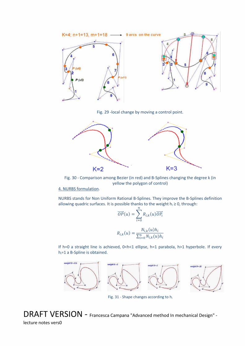
This last issue makes the curve able to change according to local variation, without distortions far from the related control points. In other words if you fix i, only blending functions for points in [ui ui+k+1) are different from zero (fig. 29).
Fig. 28 gives you an examples of how blending functions act inside the arcs. Fig. 29 shows an example of local distortion of the shape. Moving control point no.6, only arc 4, 5 and 6 are interested by the changes.
Fig. 27 - N i,k examples
Fig. 28 Blending functions definition
DRAFT VERSION - Francesca Campana "Advanced method In mechanical Design" -
lecture notes vers0
Fig. 29 -local change by moving a control point.
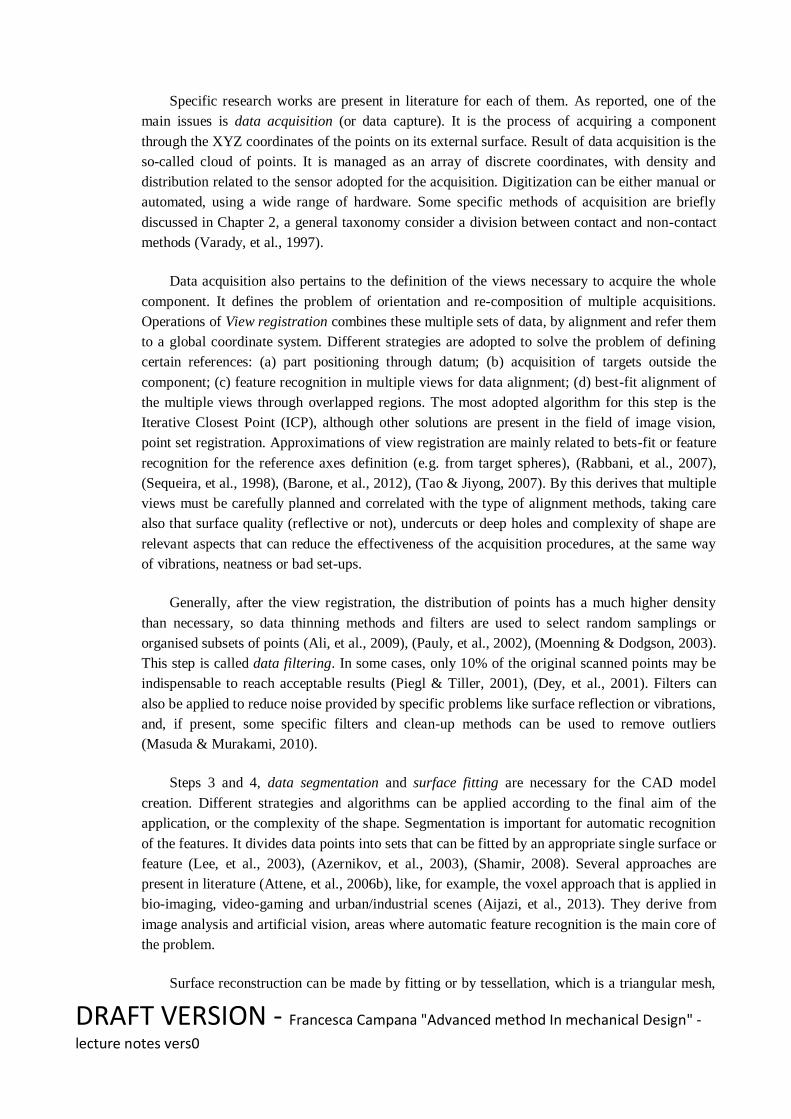
Fig. 30 - Comparison among Bezier (in red) and B-Splines changing the degree k (in
yellow the polygon of control) 4. NURBS formulation.
NURBS stands for Non Uniform Rational B-Splines. They improve the B-Splines definition allowing quadric surfaces. It is possible thanks to the weight hi ≥ 0, through:
If h=0 a straight line is achieved, 0<h<1 ellipse, h=1 parabola, h>1 hyperbole. If every hi=1 a B-Spline is obtained.
Fig. 31 - Shape changes according to hi

DRAFT VERSION - Francesca Campana "Advanced method In mechanical Design" -
lecture notes vers0
Exercises 1. Can you describe the meaning of "blending function"? Write a matlab script to plot the four blending functions of the Hermite curve and of the Bezier one. 2. According to the mathematical description of the Ni,k, try to explain why k=1 makes the curve passing through the control points. 3. According to the fig. below, if n=10 and k=3 how many knot spans are defined?, how many knots? How many arcs are in the curve?
Interesting links: - http://www.aliasworkbench.com/
1.5 Strategies for system design
CAD modeling for complex systems may involve different kinds of approach as explained in table of Section 1.3.
2D drawing tools
Feature-based design
Explicit design Computer Aided Drafting
Sketch xxx
Concept xx xx
Detailed drawing
xxx xx
Executive drawing
xxx xxx
Generally speaking, parametric design linked to formulas is extremely convenient in case of components made by featured-based shapes. For modular design and production, all the type of product can be derived changing the parameters in a specific table defined in the function called “family of parts”. It is a specific function of CAD systems, it is used to aid the solid model of many components that differ each other only for the lengths and/or small details, locally defined. This will produce a catalogue of parts starting from a table that reproduces the parameters already defined in the model of the first component (the parent component), plus selected local features that can be changed by switching on/off (e.g. delete local protrusion, pocket, hole) or by re-definition (e.g. reducing/adding the number of hole in a matrix). After the set of different component children is defined in the table (fig. 32) the solid models are populated in the catalogue one per table’s row.

DRAFT VERSION - Francesca Campana "Advanced method In mechanical Design" -
lecture notes vers0
Fig. 32 – Washing machine lateral panel definition by catalogue of parts
Surface design relevance has been already discussed in the previous sections, nevertheless another application that concerns with surface design is explicit modeling10. Thanks to the capability of managing GUI (graphical user interface) suitably to change faster control points and surface, via explicit modeling the feature-based design can be passed and substituted by NURBS modeling. Using extensively NURBS instead of feature-based design can reduce the memory efforts to store data, nevertheless delete tree structure of modeling information and recovery. It is suitable for:
- unskilled persons that design occasionally - very complex design that involves customization, or in standard design process, it
can be useful to model local details in assembly when component interaction is need (e.g. see synchronous modeling in Solid Edge).
Common feature-based products should still be made by parametric design!
1.6 File formats for data exchange
Data exchange concerns with the capability of importing and exporting models from one CAD to another. Each CAD system has its own binary file format to save components, assemblies, drawings. When proper translators are not present neutral format must be used. Neutral format means that file definition is shareware, so that each CAD system may implement a suitable translator. Obviously, this opportunity has a cost: part of the information stored in the original model can be lost or spoilt.
The most common neutral file format are: STL, IGES (or IGS), STEP.
STL approximates external surface of the components by a triangular mesh (fig. 33). It is the simplest way to approach the problem, nevertheless it looses the modeling history and parametrization, substituting it with an envelope triangularization. Volume are defined through
10
See also the paper included in the webpage of the class in file PTCProductivityWhitePaper.pdf

DRAFT VERSION - Francesca Campana "Advanced method In mechanical Design" -
lecture notes vers0
a closed mesh with consistent normals (outside or inside oriented), as defined by the clock or counterwise order of the points that define the triangles.
Fig. 33 – Example of stl translation
STL is typically provided as file format of Reverse Engineering problems and Additive Manufacturing. It is related to single components or not (if they distinguished by “material”). To be used as data exchange format, some translation options must be checked: (a) units, (b) tolerances related to max angle (deviation between effective normal to the surface and the approximated one) and point distance (to avoid degenerated triangles).
IGS provides a sort of discrete sampling of the geometrical entities inside the model (points, plane, surface, edges, …) according to the results achieved by the history of modeling (protrusion, pocket, …) . It is made by declaring “flags” that are “cards” able to identify the entity and then providing the numerical estimation (fig. 34)11.
Fig. 34 Example of igs “card” for Entity Type
11
See file IGS_STD_ANSI.pdf on the website for the ANSI standard definition of IGS cards

DRAFT VERSION - Francesca Campana "Advanced method In mechanical Design" -
lecture notes vers0
Although after import, modeling history is lost a more accurate translation of shape can be provided, and partial editing capability can be restored (it depends on the CAD model used to import). Typical errors are:
-bad overlapping of edges for complex surface patches. Generally it is due to truncation problems.
-Volume loss for small surface deletion and open surface presence.
Options to be checked before export/import are: units, tolerance for truncation, allowed formulas for curves (Bspline, nurbs, …).
STEP is another format defined to export also data information about product structure (components and geometric constraints among parts). From the shape translation point of view, it is generally more reliable than standard export solutions in igs.
Other formats can be used, representing good solutions for specific fields of applications (e.g.: VDA is the format of the German automobile association – VDA; SAT is the format from ACIS parasolid CAD Kernel).
1.7 Reverse Engineering techniques in industrial engineering 12
In industrial engineering, the creation or retrieve of geometrical models from existing objects has now become a routine. A common interpretation of the phrase “Reverse Engineering”, first used in few publications in the 1970s revolves around copying an original (Bradley & Currie, 2005). In these terms, Reverse Engineering pertains to “imitation”, meaning the process of replicating the performance of an existing product in one or more of its performance areas (Knight, et al., 2009). By this, derives that RE processes can be used by companies for benchmark purposes, to maintain a competitive position, through the extraction of specification from competitors’ products or by military powers to take an advantage over antagonists, making a “reverse-engineering” of whatever equipment they can get. However, in these cases, the definition of Reverse Engineering as reported, limits the discussion to simplify the process of information extraction.
In a broader sense, Reverse Engineering (RE) can be defined as the creation of a set of specifications for an existing part by someone different from the original designers (Rekoff, 1985). According to this, nowadays, RE technology allows the creation of a digital model using data collected from an existing component and it is essentially based on analysis and measurement of a specimen or a set of them. Researches from areas such as image processing, computer graphics, advanced manufacturing and virtual reality has converged around creating a computer-based representation of the authentic component. While conventional engineering transforms engineering concepts and models into real parts, in RE, real parts are transformed into virtual models and concepts. The existence of a computer model provides enormous gains in improving the quality and the efficiency of design, manufacture and analysis.
There are many reasons to utilise Reverse Engineering as a design methodology. For example, a
12
All the parts about RE are excerpted from Michele Bici, “Automatic tolerance inspection through Reverse Engineering: a segmentation technique for plastic injection moulded parts”, ph.d. dissertation, 2017

DRAFT VERSION - Francesca Campana "Advanced method In mechanical Design" -
lecture notes vers0
list of few common reasons can be (Curtis, et al., 2011):
To have a comparison between products through a competitive benchmarking, (Harrington, 1991), (Raja & Fernandes, 2008);
In preparation of a concrete imitation of a product, (Musker, 1998);
To obtain technical data and information that do not exist or are not available, (Pal, et al., 2006), (Creehan & Bidanda, 2006), (Urbanic & El Maraghy, 2009), one of the main example of this reason is in architectural and cultural heritage (Núñez Andrés, et al., 2012), (Sansoni & Docchio, 2005), (Sansoni, et al., 2009);
To obtain technical data that the original supplier is no longer willing or able to provide, (Thompson, et al., 1999), (Raja & Fernandes, 2008);
To reduce time-to-market, (Raja & Fernandes, 2008);
To enrich existing data and information, (Ingle, 1994);
To be able to customise product design, in fields like dentistry or orthopaedic prosthesis (Fasbinder, 2010), (Martorelli & Ausiello, 2013) (Knopf & Al-Naji, 2001);
To perform product verification, detecting and overcoming defects of a part (Ingle, 1994), (Bici, et al., 2017);
To aid in product design (Hsiao & Chuang, 2003), also using measures and quality checks to perform improvements in design (Bici, et al., 2017);
To investigate and control patent law infringement, (Ohly, 2009);
To support in academic field or other learning environments, (Ohly, 2009), (Mowery, et al., 2004);
This list is obviously not exhaustive, but it illustrates the RE flexibility. Due to this enormous set of reasons to utilise RE technologies, it is important to know what factors increase difficulties in Reverse Engineering operations. This knowledge is beneficial, both for original designers and for who is going to obtain the digital model of the component. To reduce risks of imitation, original designers can design products that are more difficult to be acquired by RE, thereby maintaining a market advantage over their competitors. On the other hand, the decision of applying RE techniques must be evaluated, keeping in mind time and cost that will be faced, taking into account the return of investments of such actions. In literature (Curtis, et al., 2011), (Raja & Fernandes, 2008), barriers in the RE process are investigated. A barrier to RE is anything that impedes the extraction of information about a product from the product itself (Harston & Mattson, 2010). Barriers to RE may include cases generated by the original designers, as the complexity of turbine blade surfaces or as inaccessibility of hidden or microscopic features of an embedded circuit. Sometimes, barriers are due to lacks of RE process as an inadequate measurement equipment, or even an inexperienced engineer with an inadequate knowledge and practice about the application of the RE techniques.
A common way to say RE, nowadays, is referring to the acquisition step through the words “3D scanner”. The meaning of “scanner”, compared to “photocopier” may give a good explanation of RE technology (Varady, et al., 1997). A photocopier produces a simple copy of an original piece of paper onto another piece of paper, a scanner, instead, inputs a page into a computer

DRAFT VERSION - Francesca Campana "Advanced method In mechanical Design" -
lecture notes vers0
but can also recognize characters and figures, providing a text file or an image file. Similarly, a 3D copier can be seen as a device that machines a copy with the same shape of a solid object (e.g. the pantographic process used for making copies of keys). On the contrary, a 3D scanner not only captures raw data from the component but also interprets data, creating a model that can be completely analysed, modified and improved.
Looking at the whole Reverse Engineering process, in literature (Barbero, 2009), (Huang & Tai, 2000), (Bradley & Currie, 2005), it is possible to recognise that an ideal RE system should not only be able to reconstruct a complete geometric model of a piece, but should also be able to capture the initial design intent. Whit this in mind, data capture is not the unique starting point of this complex process. At the same time, automated modelling of surface often is not the only final goal, leaving the door open for more interactive, knowledge driven approaches concerning the product development steps (comparison between original design intent and optimization evolution, tools for aiding design manufacturing, and so on). In this scenario, the surface acquisition must be correlated with other information, like physical characteristics of the object (surface aspect and texture, feature recognition), milling g-code (e.g. to control the process or to achieve tolerance), laser scan data or CMM data (e.g. to recover lack of information or to follow the part ID code during acquisition) (Anwer & Mathieu, 2016).
Finally, the correlation between RE and Rapid Prototyping must be cited, since often they are proposed as a natural duo, (Onuh, et al., 2001), (Jamieson & Hacker, 1995). Researches into the two technologies are often intersected and their fundamental application theory has become interrelated for several fields. Reasons concern with their common approach to manage the shape, basically, by slices (if we assume a laser scanner as a RE instrument) and STL format for the digitalization; and with the Rapid Prototyping ability of giving functional prototypes of the parts. They can be extremely useful in fields where aesthetic or manual interaction with the design is relevant, such as car-body and jewelry design (Fudos, 2006) (Stamati & Fudos, 2005), clinical, dental or biomedical applications. RE engineering, currently, is used also to acquire parts of human body (Knopf & Al-Naji, 2001), (Kim, et al., 2016) to produce prostheses or orthoses, directly through an Additive Manufacturing technology or producing, in an additive way, scaffolds or dies where, respectively, organs can be grown or materials with a comparable-to-real density can be moulded.
1.7.1 Research topics in Reverse Engineering
RE encompasses several tools and methods suitable to make digital models of real parts. As
reported in (Varady, et al., 1997), (Bradley & Currie, 2005), generally, they can be divided in a
sequence of four macro-steps:
1. Data Acquisition;
2. Data Processing;
3. Segmentation and Surface (or feature) Fitting;
4. CAD Model Creation.
Obviously, these phases are not clearly separated, often they can overlap and, sometimes, the
whole process needs to be iterated to reach an accurate solution. Nevertheless, this division in
macro-phases can help to take in mind requirements and issues to be solved.
DRAFT VERSION - Francesca Campana "Advanced method In mechanical Design" -
lecture notes vers0
Specific research works are present in literature for each of them. As reported, one of the
main issues is data acquisition (or data capture). It is the process of acquiring a component
through the XYZ coordinates of the points on its external surface. Result of data acquisition is the
so-called cloud of points. It is managed as an array of discrete coordinates, with density and
distribution related to the sensor adopted for the acquisition. Digitization can be either manual or
automated, using a wide range of hardware. Some specific methods of acquisition are briefly
discussed in Chapter 2, a general taxonomy consider a division between contact and non-contact
methods (Varady, et al., 1997).
Data acquisition also pertains to the definition of the views necessary to acquire the whole
component. It defines the problem of orientation and re-composition of multiple acquisitions.
Operations of View registration combines these multiple sets of data, by alignment and refer them
to a global coordinate system. Different strategies are adopted to solve the problem of defining
certain references: (a) part positioning through datum; (b) acquisition of targets outside the
component; (c) feature recognition in multiple views for data alignment; (d) best-fit alignment of
the multiple views through overlapped regions. The most adopted algorithm for this step is the
Iterative Closest Point (ICP), although other solutions are present in the field of image vision,
point set registration. Approximations of view registration are mainly related to bets-fit or feature
recognition for the reference axes definition (e.g. from target spheres), (Rabbani, et al., 2007),
(Sequeira, et al., 1998), (Barone, et al., 2012), (Tao & Jiyong, 2007). By this derives that multiple
views must be carefully planned and correlated with the type of alignment methods, taking care
also that surface quality (reflective or not), undercuts or deep holes and complexity of shape are
relevant aspects that can reduce the effectiveness of the acquisition procedures, at the same way
of vibrations, neatness or bad set-ups.
Generally, after the view registration, the distribution of points has a much higher density
than necessary, so data thinning methods and filters are used to select random samplings or
organised subsets of points (Ali, et al., 2009), (Pauly, et al., 2002), (Moenning & Dodgson, 2003).
This step is called data filtering. In some cases, only 10% of the original scanned points may be
indispensable to reach acceptable results (Piegl & Tiller, 2001), (Dey, et al., 2001). Filters can
also be applied to reduce noise provided by specific problems like surface reflection or vibrations,
and, if present, some specific filters and clean-up methods can be used to remove outliers
(Masuda & Murakami, 2010).
Steps 3 and 4, data segmentation and surface fitting are necessary for the CAD model
creation. Different strategies and algorithms can be applied according to the final aim of the
application, or the complexity of the shape. Segmentation is important for automatic recognition
of the features. It divides data points into sets that can be fitted by an appropriate single surface or
feature (Lee, et al., 2003), (Azernikov, et al., 2003), (Shamir, 2008). Several approaches are
present in literature (Attene, et al., 2006b), like, for example, the voxel approach that is applied in
bio-imaging, video-gaming and urban/industrial scenes (Aijazi, et al., 2013). They derive from
image analysis and artificial vision, areas where automatic feature recognition is the main core of
the problem.
Surface reconstruction can be made by fitting or by tessellation, which is a triangular mesh,

DRAFT VERSION - Francesca Campana "Advanced method In mechanical Design" -
lecture notes vers0
used to approximate shapes. Typically, it is a Delaunay triangulation (Okabe, et al., 1992). It
means that each triangle has a circumcircle that does not contains any other points except the
vertex of its triangle (Figure 1). This property makes the Delaunay triangulation a convex hull of
the points, thus of the surfaces of the cloud of points.
Figure 1. Example of Delaunay triangles (Peterson, 2017).
Surface fitting is applied on segment sets or can be derived by curve networks directly
derived from scans. More in detail, occasional applications or extremely complex free-form
surfaces may be achieved directly through surface modelling, adopting B-Spline curves directly
derived from points aligned according to laser scans. In many practical cases, coupling automatic
segmentation and surface fitting together with surfacing via scans can improve detail resolution of
complex free forms or can fix holes due to partial data acquisitions.
Obviously, there are several peculiar applications of RE that lead to methods ad-hoc for each
(e.g. the recognition of symmetry planes in (Di Angelo, et al., 2013), (Di Angelo & Di Stefano,
2014)). Into the universe of utilization and development of RE methods, there are methods of RE
used for quality and tolerance automatic inspection.
1.8 Reverse Engineering: acquisition methods
As already discussed in the previous section, data acquisition (or data capture) is the starting point
of an RE process. There are many different methods and technologies used to acquire shape and
data from a component. Essentially, each technology is characterised by specific mechanism or
phenomenon used for interacting with surfaces or volumes of the component that has to be
acquired. Mainly, RE acquisition methods can be divided in two branches:
Non-contact methods;
o Optical Systems;
o Acoustic Systems;
o Magnetic Systems.
Contact methods;
o CMM guided;

DRAFT VERSION - Francesca Campana "Advanced method In mechanical Design" -
lecture notes vers0
o Robot arms guided;
In the first case, light, sound or magnetic fields are used to acquire; in the second one, the surface
is acquired by the touch of a mechanical probe connected to several types of arm (they are also
known as tactile methods). Obviously, in each type, successive specific analysis are performed to
obtain a list of coordinates from the physical acquisitions, as, for example, in laser scanners, the
utilisation of laser’s time-of-flight to determine distance. Each single method or technology has
his pros and cons. This involves that the system must be chosen carefully, paying attention to the
characteristics of the component and to the possible results of acquiring compared to the desired
ones.
1.8.1 Non- contact methods
Nowadays, non-contact methods have reached a good level of confidence for RE (Son, et al.,
2002), (Carbone, et al., 2001), in particular for those based on laser scanner heads. This because
of the high-speed acquisition and consequently, the reduction of the relation performance-cost.
Nevertheless, historically, measurement uncertainty, for these systems, is not completely known
and definable, causing important disadvantages. Researchers (Cuesta, et al., 2009) performed
efforts to increase accuracy of laser systems, allowing the usage in inspection systems. However,
in the set of non-contact systems, several categories can be highlighted:
Triangulation;
Structured Light;
Image Analysis;
Interferometry;
Ranging.
In Triangulation methods, position of the target point is deduced through location and angles
between light sources and photo-sensing devices. Usually, the light source has a high level of
energy, and it is given out at a specified angle onto the surface of interest. Through a
photosensitive device, as, for example, a video camera, the light reflection of the surface is
acquired, and then, with geometric triangulation of the known angle and distances, the position of
a point relative to a reference plane can be calculated. Both light source and camera may be
placed on a moving platform in order to acquire multiple scans. The most common used high-
energy light source is laser. Through triangulation methods, data can be acquired with very fast
rates. The accuracy depends by the resolution of the photosensitive device and by the distance
between scanners and surfaces. (Barbero & Ureta, 2011). They are the most common laser
systems (laser stripes), because of their higher precision and lower cost with regard to other non-
contact systems such as structured light or image analysis. Scanning Laser Heads, Stereo-Vision
Systems, and Photogrammetric Systems are part of this category.
Under this point of view, Structured Light methods can be seen as particular type of triangulation.
These methods, among which is included the Moirè method, are used through the projection of
light patterns upon a surface, capturing an image of the resulting pattern reflected by the
component. Then, the resulting image must be analysed in order to obtain coordinates of surface
points. These methods can acquire large amounts of data with a single image. In spite of this, the

DRAFT VERSION - Francesca Campana "Advanced method In mechanical Design" -
lecture notes vers0
image analysis can be very complex.
In addition, Image Analysis are similar to the structured light ones, but they do not rely on
projected patterns, using stereo pairs in order to obtain enough information to determine height
and coordinate position. This type of methods are difficult to be used, because of the complex
correlation of image pairs and of the research of landmarks in them. Some examples of these
methods are Shape from X and Texture Gradients.
Interferometry methods can measure distances through wavelengths utilising interference
patterns. These methods have a very high level of accuracy due to the fact that visible light has a
wavelength of the order of hundreds of nanometres (nm), compatible with most of the RE
applications. Obviously, in some applications, other parts of the electromagnetic spectrum can
also be utilised. Practically, through a light source of high energy both a beam of monochromatic
light to probe the components and a reference beam for comparison with the reflected light can be
provided.
There are, obviously, several other methods, for example Ranging ones which are based on the
measurement of time-of-flight of a light ray, typically laser or pulsed light.
A resume of specific properties of each considered non-contact method is reported in Table 1.
Sen
sib
ilit
y
Sp
eed
Rob
ust
ne
ss
Per
form
a
nce
/
cost
s Laser Triangulation + - + + - +
Structured Light + +
+ + -
+
+
Stereo Vision + - - +
Photogrammetry + - + - + -
Time of flight + - + -
Interferometry +
+ + + - + -
Moiré fringe range
Contours + - + - -
Shape from focusing - +
+ - + -
Shape from shadows - +
+ - + -

DRAFT VERSION - Francesca Campana "Advanced method In mechanical Design" -
lecture notes vers0
Texture gradients - + + - + -
Shape from shading - +
+ - + -
Table 1. List of non-contact acquisition methods and general comparison regarding some properties
(sensibility, speed, robustness, relation between performances and costs), (Broggiato, et al., 2002).
Other methods can be included in the non-contact set, but seen as hybrid. In fact, for these
techniques, sensors must be in contact or drowned with mediums of wave propagation. These
types of data acquisition methods are acoustic, in which sound waves are reflected by a surface,
and magnetic, in which a magnetic field is interfaced with the surface. Acoustic methods have
been utilised, for a long period, for distance measuring, e.g. the sonars. Sometimes acoustic
methods have been integrated into automatic focus cameras in order to determine range, with a
method similar to the time-of-flight one, launching a sound wave from a source, making it
reflected of by a surface, calculating the distance by the knowledge of sound speed. Often, these
methods have interference or noise problems, in addition to a low level of accuracy. Measurement
of a magnetic field involves an evaluation of the strength of a magnetic field source. Though the
usage of magnetic touch probes, it is possible to obtain the location and the orientation of a stylus
within the field. Usually, a trigger allows the user to record only specific point data, when the
stylus is positioned at a point of interest. Magnetic resonance is utilised in application similar to
the ultrasound methods, in order to acquire internal material and defects. For example, MRI
(Magnetic Resonance Imaging) activates atoms in the material, measuring the response.
1.8.2 Contact methods
The other branch of RE method is represented by contact (or tactile) methods. They use
mechanical arms to touch the surface and obtain a data acquisition, determining the relative
coordinate locations through the placement of sensing devices in the joints of the arms. These
methods are limited by the physical constraints on measuring devices. For example, a tactile
measuring system can be obtained mounting a touch probe on a 3-axes milling machine, but it
could not be useful for acquiring concave surfaces. These methods are considered the most robust
because of a general less noise, and more accuracy and repeatability, but they are practically not
competitive in terms of acquisition speed. In fact, one of the main disadvantages of these contact
systems is the high operation time required to obtain a large set of points of each surface, and this
time increases as much as the surfaces to be controlled are more complex.
The most common used tactile method is with touch-trigger probes mounted on a Coordinate
Measuring Machines (CMM).

DRAFT VERSION - Francesca Campana "Advanced method In mechanical Design" -
lecture notes vers0
Figure 2. Different mechanical structures of CMMs.
Typically, their handling systems are 3-axes (see in Figure 6, examples of different types of
CMMs) and they can be programmed to follow paths along a surface or a plane. They can collect
data with a very high level of accuracy, until, in some cases, 1µm, nearly noise-free. For this
reason, they are used in operations for control of dimensional and geometrical tolerances (GD&T)
and inspections with contact (touching probes) and non-contact (principally with laser heads)
systems (Martínez, et al., 2010). In contact technologies, CMMs have the leadership for tolerance
and quality control processes (Li & Gu, 2004), because of the known process of calibration of
those machines and the low uncertainty in measurement. In fact, in case of non-contact systems,
the uncertainty has values at least one order of magnitude higher than the contact ones (Feng, et
al., 2001). However, in the recent years, some improvements has been performed, reaching
competitive values or trying to define calibration procedures for 3D scanners similar to that
defined by the ISO 10360-2 (ISO10360-2, 2009) for CMMs (Genta, et al., 2016). Contact
processes with touch-trigger probes are commonly used due to their good relation between
performances and costs.
Contact CMM measurement typologies depend not only by the machine but also by the mounted
probe; they can be categorised into two sets:
Point-to-point: each point is acquired at a time, and the probe leaves the surface after each
acquisition of single point. One of the main con of this method is the low speed of acquisition due
to all the time lost moving the probe.
Scan: the probe is always in contact with the surface, the measurement is in a continuous
manner, giving the possibility to acquire points quite faster than the point-to-point method.
Some requirements of a CMM, in order to obtain a good acquisition, can be highlighted: static
and dynamic stiffness, possibility to have several blocking and grasping system in order to
change orientations of pieces, accessibility for maintenance and handling easiness.
1.8.3 System performance and hardware selection

DRAFT VERSION - Francesca Campana "Advanced method In mechanical Design" -
lecture notes vers0
Generally speaking, every measuring method has to interact with the surface, plane, feature or
internal material through a phenomenon or a union of them. The speed with which the
phenomenon operates and the typical speed of the sensor device, obviously determines the speed
of the data acquisition. The selected sensor type also influences the accuracy and the amount of
analysis needed to compute acquired data.
Major problems, connected to the practice, in these procedures are (Varady, et al., 1997):
Calibration. It is, obviously, an indispensable part of the set-up, which may influence
negatively the rest of the procedure. Systematic errors may be caused by lens distortions, non-
linear electronics in cameras, wrong positioning of the acquiring table, and other similar causes.
Calibration operations are necessary to obtain fundamental parameters as orientations and
position of cameras or probes and to determine the values of eventual systematic sources of
errors. In fact, this issue could be extremely influencing for results accuracy in non-contact
systems.
Accessibility. Sometimes, because of the peculiar topology or configuration of the
component to be acquired, obtain usable data could be extremely difficult. Common examples of
inaccessible surfaces are holes and their internal cylindrical surfaces. Generally, problems of
accessibility can be solved, or attenuated, through multiple scans or acquisitions. Problems of
accessibility have different connotations depending of the type of method. In non-contact ones, it
depends from reciprocal orientations of scanner and component, and to the feature specific
dimensions (e.g. an hole could be completely acquirable or not regards to its ratio between height
and radius). In contact systems, it is also function of the dimensions of probe and handling
system.
Accuracy. As explained, it depends about the type of system and its quality chosen or
available. In optical systems, accuracy is dependant mainly from the resolution of the used
camera. In addition, distances between sensors (of both type of methods) and measured surface,
and the accuracy of the moving parts or arms can contribute to the overall measurement error. In
contact systems, it is influenced by the different mechanical structure of the handling systems
(Figure 6).
Occlusion. It is caused by shadowing or obstruction of scanners and sometimes, also, of
probes. This type of issue, extremely dependant by the disposition of pieces or their
conformation, is solved with acoustic and magnetic systems, or with the usage of multiple
scanning ones. For contact systems, solutions, when existing, for this issue, may require different
positioning and fixturing of pieces.
Fixturing. Similarly to the self-occlusion or to occlusion often caused by the multi-pieces
positioning, some occlusions can arise by the typology of clamping and blocking systems. Often,
but only in non-contact systems, the clamping system is acquired together with the piece,
becoming part of the scan data. Elimination and cleaning of fixture data can be extremely difficult
and may need multiple views.
Multiple Views. The usage of multiple view is important for solving problems arisen from
occlusion and inaccessibility, but often they introduce errors due to registration problems.
Naturally, “view” is a term proper, conceptually, of the non-contact acquisitions, but the same
problems are present in contact methods while partial point clouds need to be merged. The

DRAFT VERSION - Francesca Campana "Advanced method In mechanical Design" -
lecture notes vers0
general problem is to define references and it can be solved in several ways, as, for example, part
positioning through datum, acquisition of targets outside the component, feature recognition in
multiple views or with best-fit alignment of the multiple views through overlapping operations
(Rabbani, et al., 2007), (Gagnon, et al., 1994), (Yau, et al., 2000).
Noise and Incomplete Data. Sometimes, elimination of noise in a data caption is not an easy
issue, principally due to the fact that noise can be introduced in many ways as, for example,
extraneous vibrations (for contact systems), specular reflections (in non-contact case), etc.
Through filtering approaches, those problems can be moderated or eliminated but the user have to
choose accurately the moment in the RE procedure when the operation of filtering has to be done.
The operation of filtering may destroy the natural distribution and “sharpness” of data, resulting
smoothed regions instead of sharp edges, and this process is not ever desirable because sometimes
it leads to difficulties in identification of features. For missing or incomplete data, there are
similar problems when a restoration operation has to be done. Missing or incomplete data are due
to causes like inaccessibility and occlusions.
Surface Finish. Often, smoothness and layers can affect significantly the data acquisition. In
these cases, there is an increased production of noise respect to a smooth surface. Reflective
coatings or layers can also affect the accuracy of optical methods. This problem is solved using
white-mat paint, which unfortunately introduce a thickness of material that, in some ranges, can
influence the measurement.
To be Delivered soon
1.9 Reverse Engineering: post-processing
1.10 Reverse Engineering: case studies and applications
1.11 Exercises
References
Aijazi, A. K., Checchin, P. & Trassoudaine, L., 2013. Segmentation Based Classification of 3D Urban Point Clouds: A Super-Voxel Based
Approach with Evaluation. Remote Sensor, Volume 5, pp. 1624-1650.
Akselrod-Ballin, A. et al., 2006. An integrated segmentation and classification approach applied to multiple sclerosis analysis. s.l., s.n.,
pp. 1122-1129.
Alemán, J. et al., 2007. Definitions of terms relating to the structure and processing of sols, gels, networks, and inorganic-organic
hybrid materials (IUPAC Recommendations 2007). Pure and Applied Chemistry, 79(10), pp. 1801-1829.
Ali, F., Chowdary, B. V. & Imbert, C. A., 2009. Part design and evaluation through reverse engineering approach. International Journal
of Agile Manufacturing, 11(1), pp. 73-82.
Almasi, G. S. & Gottlieb, A., 1989. Highly Parallel Computing. Redwood City, CA, USA: Benjamin-Cummings Publishing Co., Inc..
Al-Sharadqah, A. & Chernov, N., 2009. Error analysis for circle fitting algorithms. Electronic Journal of Statistics. 3, 886-- 911., Volume
3, pp. 886-911.
Ameri, F. & Dutta, D., 2005. Product Lifecycle Management: Closing the Knowledge Loops. Computer-Aided Design and Applications,
2(5), pp. 577-590.
Amodio, D. et al., 2001. Automated defect detection on stamped panels by strain analysis and shape assessment. Ancona (Italy), s.n.

DRAFT VERSION - Francesca Campana "Advanced method In mechanical Design" -
lecture notes vers0
Anwer, N. & Mathieu, L., 2016. From reverse engineering to shape engineering in mechanical design. CIRP Annals, 65(1), pp. 165-
168.
Attene, M., Falcidieno, B. & Spagnuolo , M., 2006. Hierarchical mesh segmentation based on fitting primitives. The Visual Computer,
22(3), p. 181–193.
Attene, M. et al., 2006b. Mesh Segmentation - A Comparative Study. Washington, DC, USA, IEEE Computer Society.
Audfray, N., Mehdi-Souzani, C. & Lartigue, C., 2013. A Novel Approach for 3D Part Inspection Using Laser-plane Sensors. Procedia
CIRP, Volume 10, pp. 23-29.
Azernikov, S., Miropolsky, A. & Fischer, A., 2003. Surface reconstruction of freeform objects based on multiresolution volumetric
method. New York, NY, USA, ACM, pp. 115-126.
Babahajiani, P., Fan, L., Kamarainen, J. & Gabbouj, M., 2016. Automated super-voxel based features classification of urban
environments by integrating 3D point cloud and image content. s.l., s.n., pp. 372-377.
Baeurle, S. A., Hotta, A. & Gusev, A. A., 2006. On the glassy state of multiphase and pure polymer materials. Polymer, 47(17), pp.
6243-6253.
Barbero, B. R., 2009. The recovery of design intent in reverse engineering problems. Computers & Industrial Engineering, Volume 56,
pp. 1265-1275.
Barbero, B. R. & Ureta, E. S., 2011. Comparative study of different digitization techniques and their accuracy. CAD Computer Aided
Design, 43(2), pp. 188-206.
Barone, S., Paoli, A. & Razionale, A. V., 2012. Three-dimensional point cloud alignment detecting fiducial markers by structured light
stereo imaging. Machine Vision and Applications, 23(2), pp. 217-229.
Beiter, K. A. & Ishii, K., 1997. Incorporating dimensional requirements into material selection and design of injection molded parts.
s.l., s.n., p. 3295–3299.
Benko, P., Martin, R. R. & Varady, T., 2001. Algorithms for reverse engineering boundary representation models. Computer-Aided
Design, 33(11), pp. 839-851.
Benko, P. & Varady, T., 2004. Segmentation methods for smooth point regions of conventional engineering objects. Computer-Aided
Design, Volume 36, pp. 511-523.
Bici, M., Broggiato, G. B., Campana, F. & Dughiero, A., 2017. Computer Aided Inspection Procedures to Support Smart Manufacturing
of Injection Moulded Components. Procedia Manufacturing, Volume 11, pp. 1184-1192.
Bici, M., Campana, F., Petriaggi, S. & Tito, L., 2014. Study of a Point Cloud Segmentation with Part Type Recognition for Tolerance
Inspection of Plastic Components via Reverse Engineering. Computer-Aided Design and Application, 11(6), pp. 640-648.
Bici, M., Campana, F. & Trifirò, A., 2016. Automatic post-processing for tolerance inspection of digitized parts made by injection
moulding. Computer-Aided Design and Applications, 13(6), pp. 835-844.
Bici, M., Campana, F., Trifirò, A. & Testani, C., 2014b. Development of automatic tolerance inspection through Reverse Engineering.
Benevento, Italy, s.n., pp. 107-112.
Bi, Z. M. & Wang , L., 2010. Advances in 3D data acquisition and processing for industrial applications. Robotics and Computer-
Integrated Manufacturing, 26(5), pp. 403-413.
Bradley, C. & Currie, B., 2005. Advances in the Field of Reverse Engineering. Computer-Aided Design and Applications, 2(5), pp. 697-
706.
Broggiato, G. B., Campana, F. & Gerbino, S., 2001. Shape deviation analysis on sheet metal parts through reverse engineering
techniques. Rimini, Italy, s.n.
Broggiato, G. B., Campana, F., Gerbino, S. & Martorelli, M., 2002. Confronto tra diverse tecniche di digitalizzazione delle forme per il
reverse engineering. Santander, Spain, XIV Congreso Internacional de Ingeniería Gráfica.
Buonamici, F., Carfagni, M. & Volpe, Y., 2017. Recent strategies for 3D reconstruction using Reverse Engineering: a bird's eye view.
In: B. Eynard, et al. a cura di Advances on Mechanics, Design Engineering and Manufacturing : Proceedings of the International Joint
Conference on Mechanics, Design Engineering & Advanced Manufacturing (JCM 2016). Catania, Italy: Springer International
Publishing, pp. 841-850.
Busick, D. R., Beiter , K. A. & Ishii, K., 1994. Design for injection molding: Using process simulation to assess tolerance feasibility.
Computers in Engineering, Proceedings of the International Conference and Exhibit, 1(-), pp. 113-120.
Campana, F. & Germani, M., 2008. Datum identification for tolerance control on dense clouds of points. Computer-Aided design and
Applications, 5(1-4), pp. 209-219.

DRAFT VERSION - Francesca Campana "Advanced method In mechanical Design" -
lecture notes vers0
Campbell, R. J. & Flynn, P. J., 2001. A Survey Of Free-Form Object Representation and Recognition Techniques. Computer Vision and
Image Understanding, 81(2), pp. 166-210.
Cao, H. & Folan, P., 2012. Product life cycle: the evolution of a paradigm and literature review from 1950–2009. Production Planning
& Control, 23(8), pp. 641-662.
Carbone, V. et al., 2001. Combination of a vision system and a coordinate measuring machine for the reverse engineering of
freeform surfaces. International Journal of Advanced Manufacturing Technology, 17(4), pp. 263-271.
Che, C. & Ni, J., 2000. A ball-target-based extrinsic calibration technique for high-accuracy 3-D metrology using off-theshelf laser-
stripe sensors. Precision Engineering, 24(3), pp. 210-219.
Courtial, A. & Vezzetti, E., 2008. New 3d segmentation approach for reverse engineering selective sampling acquisition. The
International Journal of Advanced Manufacturing Technology, 35(9), pp. 900-907.
Creehan, K. D. & Bidanda, B., 2006. Reverse engineering: a review & evaluation of non-contact based systems. In: Rapid prototyping:
theory and practice. s.l.:Springer US, pp. 87-106.
Cuesta, E. et al., 2009. Influence of roughness on surface scanning by means of a laser stripe system. International Journal of
Advanced Manufacturing Technology, 43(11-12), pp. 1157-1166.
Curless, B. & Levoy, M., 1996. Volumetric method for building complex models from range images. s.l., s.n., pp. 303-312.
Curtis, S. K., HarstonS., S. P. & Mattson, C. A., 2011. The fundamentals of barriers to reverse engineering and their implementation
into mechanical components. Research in Engineering Design, 22(4), pp. 245-261.
Curtis, S. K., Harston, S. P. & Mattson, C. A., 2009. A Generic Formulaic Characterization of the Time to Reverse Engineer the
Tolerances of a Product. Lake Buena Vista, Florida, USA, ASME, pp. 275-285.
Custom Part Net, 2017. Custom Part Net. [Online]
Available at: http://www.custompartnet.com
Das, A., Franciosa, P., Pesce, A. & Gerbino, S., 2017. Parametric effect analysis of free-form shape error during sheet metal forming.
International Journal of Engineering Science and Technology, 9(09S), pp. 117-124.
Davis, J. et al., 2015. Smart Manufacturing. Annual Review of Chemical and Biomolecular Engineering, 6(1), pp. 141-160.
De, S. K., 1996. Rubber Technologist's Handbook. First Edition a cura di s.l.:Smithers Rapra Press.
Dey, T. K., Giesen, J. & Hudson, J., 2001. Decimating samples for mesh simplification. Waterloo, Canada, s.n., pp. 85-88.
Di Angelo, L. & Di Stefano, P., 2014. A computational Method for Bilateral Symmetry Recognition in Asymmetrically Scanned Human
Faces. Computer-Aided Design and Applications, 11(3), pp. 275-283.
Di Angelo, L. & Di Stefano, P., 2015. Geometric segmentation of 3D scanned surfaces. Computer Aided Design, Volume 62, pp. 44-56.
Di Angelo, L., Di Stefano, P. & Morabito , A. E., 2012. The RGM data structure: a nominal interpretation of an acquired high point
density model for automatic tolerance inspection. International Journal of Production Research, 50(12), pp. 3416-3433.
Di Angelo, L., Di Stefano, P. & Morabito, A. E., 2011. Automatic evaluation of form errors in high-density acquired surfaces.
International Journal of Production Research, 49(7), pp. 2061-2082.
Di Angelo, L., Di Stefano, P. & Morabito, A. E., 2013. Recognition of intrinsic quality properties for automatic geometric inspection.
Int. J. on Inter. Des. and Manufact., 7(4), pp. 203-215.
Di Angelo, L., Di Stefano, P. & Morabito, A. E., 2017. Product model for Dimensioning, Tolerancing and Inspection. In: B. Eynard, et al.
a cura di Advances on Mechanics, Design Engineering and Manufacturing: Proceedings of the International Joint Conference on
Mechanics, Design Engineering & Advanced Manufacturing (JCM 2016). Catania, Italy: Springer International Publishing, pp. 1033-
1040.
Di Angelo, L., Di Stefano, P. & Spezzaneve, A., 2013. A method for 3D detection of symmetry line in asymmetric postures. Computer
Methods in Biomechanics and Biomedical Engineering, 16(11), pp. 1213-1220.
Di Stefano, P., Bianconi, F. & Di Angelo, L., 2004. An approach for feature semantics recognition in geometric models. Computer-
Aided Design, 36(10), pp. 993-1009.
Ding, L.-j., Dai, S.-g. & Mu, P.-a., 2016. CAD-Based Path Planning for 3D Laser Scanning of Complex Surface. Procedia Computer
Science, 92(Supplement C), pp. 526-535.
Dutailly, B. et al., 2009. 3D surface reconstruction using HMH algorithm. s.l., s.n., pp. 2505-2508.
Fasbinder, D. J., 2010. Digital dentistry: innovation for restorative treatment. Compendium of continuing education in dentistry
(Jamesburg, N.J. : 1995), 31(4), pp. 2-11.

DRAFT VERSION - Francesca Campana "Advanced method In mechanical Design" -
lecture notes vers0
Feng, H.-Y., Liu, Y. & Xi, F., 2001. Analysis of digitizing errors of a laser scanning system. Precision Engineering, 25(3), pp. 185-191.
Fudos, I., 2006. CAD/CAM Methods for Reverse Engineering: A Case Study of Re-engineering Jewelry. Computer-Aided Design and
Applications, 3(6), pp. 683-700.
Gabbia, A., 2016b. PMI: Product Manufacturing Information. Brescia, Italy, CMM Club, pp. 16-19.
Gabbia, A., 2016. ISO 14405-1:Dimensioni lineari. Brescia, Italy, CMM Club, pp. 2-7.
Gagnon, H., Soucy, M., Bergevin, R. & Laurendeau, D., 1994. Registration of multiple range views for automatic 3-D model building.
s.l., s.n., pp. 581-586.
Gao, J., Gindy, N. & Chen, X., 2006. An automated GD&T inspection system based on non-contact 3D digitization. International
Journal of Production Research, 44(1), pp. 117-134.
Genta, G., Minetola, P. & Barbato, G., 2016. Calibration procedure for a laser triangulation scanner with uncertainty evaluation.
Optics and Lasers in Engineering, Volume 86, pp. 11-19.
Germani, M., Mandorli, F., Mengoni, M. & Raffaeli, R., 2010. CAD-based environment to bridge the gap between product design and
tolerance control. Precision Engineering, 34(1), pp. 7-15.
Harrington, H. J., 1991. Business process improvement: the breakthrough strategy for total quality, productivity, and competitiveness.
s.l.:McGraw-Hill Professional.
Harston, S. P. & Mattson, C. A., 2010. Metrics for evaluating the barrier and time to reverse engineer a product. s.l., s.n., pp.
0410091-0410099.
Hsiao, S. W. & Chuang, J. C., 2003. A reverse engineering based approach for product form design. Des. Stud., 24(2), pp. 155-171.
Huang, M. C. & Tai, C. C., 2000. The pre-processing of data points for curve fitting in reverse engineering. The International Journal of
Advanced Manufacturing Technology, Volume 16, p. 635–642.
Huang, M. C. & Tai, C. C., 2001. Effective factors in the warpage problem of an injection-molded part with a thin shell feature.
Journal of Materials Processing Technology, 110(4), pp. 1-9.
Ingle, K. A., 1994. Reverse engineering. New York, NY: McGraw-Hill.
ISO10360-2, 2009. Geometrical product specifications (GPS) -- Acceptance and reverification tests for coordinate measuring machines
(CMM) -- Part 2: CMMs used for measuring linear dimensions. s.l.:s.n.
ISO14405-1, 2016. Geometrical product specifications (GPS) -- Dimensional tolerancing -- Part 1: Linear sizes. s.l.:s.n.
ISO14405-2, 2011. Geometrical product specifications (GPS) -- Dimensional tolerancing -- Part 2: Dimensions other than linear sizes.
s.l.:s.n.
ISO14638, 2015. Geometrical product specifications (GPS) -- Matrix model. s.l.:s.n.
ISO16792, 2015. Technical product documentation -- Digital product definition data practices. s.l.:s.n.
ISO2011, 2004. Geometrical product specifications (GPS). Geometrical tolerancing. Tolerances of form, orientation, location and run-
out. s.l.:s.n.
Jamieson, R. & Hacker, H., 1995. Direct slicing of CAD models for rapid prototyping. Rapid Prototyping Journal, 1(2), pp. 4-12.
Kaisarlis, G. J., 2012. A Systematic Approach for Geometrical and Dimensional Tolerancing in Reverse Engineering. In: InTech, a cura
di Reverse Engineering - Recent Advances and Applications. s.l.:Dr. A.C. Telea (Ed.).
Kasa, I., 1976. A circle fitting procedure and its error analysis. IEEE Transactions on Instrumentation and Measurement, IM-25(1), pp.
8-14.
Keller, P., Hering-Bertram, M. & Hagen, H., 2007. Reverse engineering with subdivision surfaces. Computing, 79(2-4), pp. 119-129.
Keller, P., Hering-Bertram, M. & Hagen, H., 2012. Surface Reconstruction from Unorganized 3D Point Clouds. In: InTech, a cura di
Reverse Engineering - Recent Advances and Applications. s.l.:Dr. A.C. Telea (Ed.).
Kim, G. B. et al., 2016. Three-Dimensional Printing: Basic Principles and Applications in Medicine and Radiology. Korean Journal of
Radiology, 17(2), pp. 182-197.
Knight, D. C., Mattson, C. A. & Adams, B. L., 2009. Maximizing return on investment by constructing optimal barriers against
competitors’ market entry. Palm Springs, AIAA.
Knopf, G. & Al-Naji, R., 2001. Adaptive reconstruction of bone geometry from serial cross-section. Atificial Intelligence in Engineering,
Volume 15, pp. 227-239.
Lee, K. H. & Park, H., 2000. Automated inspection planning of free-form shape parts by laser scanning. Robotics and Computer-

DRAFT VERSION - Francesca Campana "Advanced method In mechanical Design" -
lecture notes vers0
Integrated Manufacturing, 16(4), pp. 201-210.
Lee, Y., Park, S., Jun, Y. & Choi, W. C., 2003. A robust approach to edge detection of scanned point data. International Journal of
Advanced Manufacturing Technology, Volume 23, pp. 263-271.
Li, Y. & Gu, P., 2004. Free-form surface inspection techniques state of the art review. Computer-Aided Design, 36(13), pp. 1395-1417.
Mahmud, M. et al., 2011. 3D part inspection path planning of a laser scanner with control on the uncertainty. Computer-Aided
Design, 43(4), pp. 345-355.
Malloy, R. A., 1994. Plastic part design for injection molding: an introduction. Munich: Hanser.
Martínez, S., Cuesta, E., Barreiro, J. & Álvarez, B., 2010. Analysis of laser scanning and strategies for dimensional and geometrical
control. International Journal of Advanced Manufacturing Technologies, 46(5), pp. 621-629.
Martínez, S., Cuesta, E., Barreiro, J. & Fernández, P., 2008. Testing the capabilities of the three-spheres alignment method for laser
triangulation sensors. Tallinn, Estonia, s.n.
Martorelli, M. & Ausiello, P., 2013. A novel approach for a complete 3D tooth reconstruction using only 3D crown data. International
Journal on Interactive Design and Manufacturing, 7(2), pp. 125-133.
Masuda, H. & Murakami, K., 2010. A study on smooth surface reconstruction from large-scale noisy point-clouds (1st Report) -
Smoothing operators based on robust estimate. Journal of the Japan Society for Precision Engineering, 76(5), pp. 582-586.
McNaught, A. D. & Wilkinson, A., 1997. Compendium of Chemical Terminology. Second Edition a cura di s.l.:Blackwell Science.
Mehdi-Souzani, C., Thiébau, F. & Lartigue, C., 2006. Scan Planning Strategy for a General Digitized Surface. Journal of Computing and
Information Science in Engineering (ASME), 6(4), pp. 331-339.
Meneghello, R., Savio, E. & Concheri, G., 2003. CAD based Measurements in Profile Tolerances Verification. Aachen, Germany, s.n.,
pp. 483-486.
Milroy, M. J., Weir, D. J., Bradley, C. & Vickers, G., 1996. Reverse engineering employing a 3D laser scanner: A case study.
International Journal of Advanced Manufacturing Technology, 12(2), pp. 111-121.
Moenning, C. & Dodgson, N. A., 2003. A new point cloud simplification algorithm. Spain, s.n.
Mowery, K. A., Blanchard, D. E., Smith, S. & Betts, T. A., 2004. Investigation of imposter perfumes using GC-MS. Journal of Chemical
Education, 81(1), pp. 87-89.
Musker, D. C., 1998. Reverse engineering. s.l., s.n.
Nikon Metrology, 2017. Nikon Metrology Products. [Online]
Available at: https://www.nikonmetrology.com
Noble, J. A., 1995. From inspection to process understanding and monitoring: a view on computer vision in manufacturing. Image
and Vision Computing, 13(3), pp. 197-214.
Núñez Andrés, A., Buill Pozuelo, F., Regot Marimón, J. & de Mesa Gisbert, A., 2012. Generation of virtual models of cultural heritage.
Journal of Cultural Heritage, 13(1), pp. 103-106.
Ohly, A., 2009. Reverse engineering: unfair competition or catalyst for innovation?. In: Patents and technological progress in a
globalized world. 6th edn a cura di s.l.:Springer-Verlag, p. 535–552.
Okabe, A., Boots, B., Sugihara, K. & Sung, N. C., 1992. Spatial Tessellations: Concepts and Applications of Voronoi Diagrams. New
York, USA: Wiley.
Onuh, S., Bennett, N. & Baker, J., 2001. Rapid prototyping: Pratical approach to enabling reverse engineering. Proceedings of SPIE -
The International Society for Optical Engineering, Volume 4566, pp. 145-151.
Orazi, L. & Tani, G., 2007. Geometrical inspection of designed and acquired surfaces. The International Journal of Advanced
Manufacturing Technology, 34(1), pp. 149-155.
Pal, D. K., Ravi, B., Bhargava, L. S. & Chandrasekhar, U., 2006. Computer aided reverse engineering for replacement parts: a case
study. Def. Sci. J., 56(2), pp. 225-238.
Pauly, M., Gross, M. & Kobbelt, L. P., 2002. Efficient simplification of point sampled surfaces. Boston, US, s.n.
Peterson, S., 2017. Computing Constrained Delaunay Triangulations. [Online]
Available at: http://www.geom.uiuc.edu/~samuelp/del_project.html
Piegl, L. A. & Tiller, W., 2001. Parameterization for surface fitting in reverse engineering. Computer-Aided Design, 33(8), pp. 593-603.
Prieto, F., Lepage, R., Boulanger, P. & Redarce, T., 2003. A CAD-based 3D data acquisition strategy for inspection. Machine Vision &
Applications, 15(2), pp. 76-91.
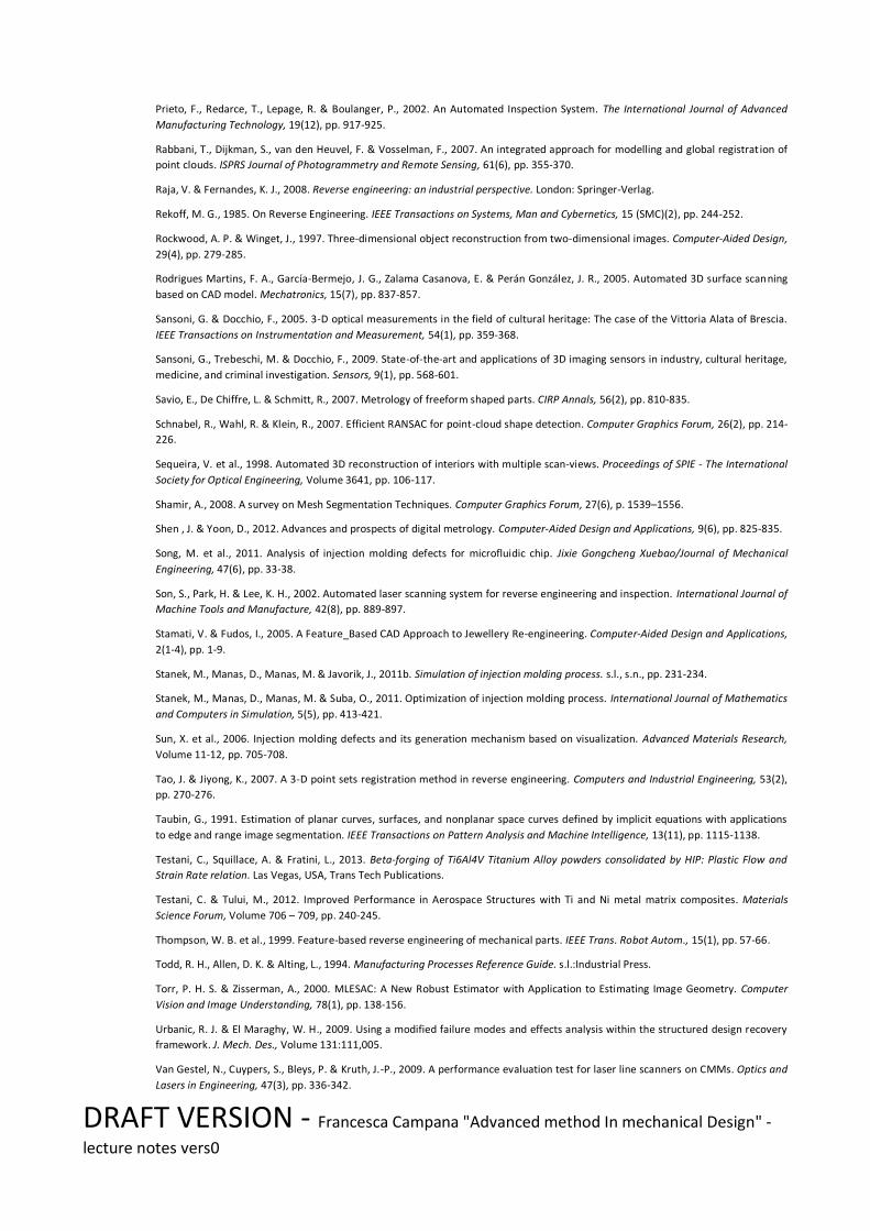
DRAFT VERSION - Francesca Campana "Advanced method In mechanical Design" -
lecture notes vers0
Prieto, F., Redarce, T., Lepage, R. & Boulanger, P., 2002. An Automated Inspection System. The International Journal of Advanced
Manufacturing Technology, 19(12), pp. 917-925.
Rabbani, T., Dijkman, S., van den Heuvel, F. & Vosselman, F., 2007. An integrated approach for modelling and global registrat ion of
point clouds. ISPRS Journal of Photogrammetry and Remote Sensing, 61(6), pp. 355-370.
Raja, V. & Fernandes, K. J., 2008. Reverse engineering: an industrial perspective. London: Springer-Verlag.
Rekoff, M. G., 1985. On Reverse Engineering. IEEE Transactions on Systems, Man and Cybernetics, 15 (SMC)(2), pp. 244-252.
Rockwood, A. P. & Winget, J., 1997. Three-dimensional object reconstruction from two-dimensional images. Computer-Aided Design,
29(4), pp. 279-285.
Rodrigues Martins, F. A., García-Bermejo, J. G., Zalama Casanova, E. & Perán González, J. R., 2005. Automated 3D surface scanning
based on CAD model. Mechatronics, 15(7), pp. 837-857.
Sansoni, G. & Docchio, F., 2005. 3-D optical measurements in the field of cultural heritage: The case of the Vittoria Alata of Brescia.
IEEE Transactions on Instrumentation and Measurement, 54(1), pp. 359-368.
Sansoni, G., Trebeschi, M. & Docchio, F., 2009. State-of-the-art and applications of 3D imaging sensors in industry, cultural heritage,
medicine, and criminal investigation. Sensors, 9(1), pp. 568-601.
Savio, E., De Chiffre, L. & Schmitt, R., 2007. Metrology of freeform shaped parts. CIRP Annals, 56(2), pp. 810-835.
Schnabel, R., Wahl, R. & Klein, R., 2007. Efficient RANSAC for point-cloud shape detection. Computer Graphics Forum, 26(2), pp. 214-
226.
Sequeira, V. et al., 1998. Automated 3D reconstruction of interiors with multiple scan-views. Proceedings of SPIE - The International
Society for Optical Engineering, Volume 3641, pp. 106-117.
Shamir, A., 2008. A survey on Mesh Segmentation Techniques. Computer Graphics Forum, 27(6), p. 1539–1556.
Shen , J. & Yoon, D., 2012. Advances and prospects of digital metrology. Computer-Aided Design and Applications, 9(6), pp. 825-835.
Song, M. et al., 2011. Analysis of injection molding defects for microfluidic chip. Jixie Gongcheng Xuebao/Journal of Mechanical
Engineering, 47(6), pp. 33-38.
Son, S., Park, H. & Lee, K. H., 2002. Automated laser scanning system for reverse engineering and inspection. International Journal of
Machine Tools and Manufacture, 42(8), pp. 889-897.
Stamati, V. & Fudos, I., 2005. A Feature_Based CAD Approach to Jewellery Re-engineering. Computer-Aided Design and Applications,
2(1-4), pp. 1-9.
Stanek, M., Manas, D., Manas, M. & Javorik, J., 2011b. Simulation of injection molding process. s.l., s.n., pp. 231-234.
Stanek, M., Manas, D., Manas, M. & Suba, O., 2011. Optimization of injection molding process. International Journal of Mathematics
and Computers in Simulation, 5(5), pp. 413-421.
Sun, X. et al., 2006. Injection molding defects and its generation mechanism based on visualization. Advanced Materials Research,
Volume 11-12, pp. 705-708.
Tao, J. & Jiyong, K., 2007. A 3-D point sets registration method in reverse engineering. Computers and Industrial Engineering, 53(2),
pp. 270-276.
Taubin, G., 1991. Estimation of planar curves, surfaces, and nonplanar space curves defined by implicit equations with applications
to edge and range image segmentation. IEEE Transactions on Pattern Analysis and Machine Intelligence, 13(11), pp. 1115-1138.
Testani, C., Squillace, A. & Fratini, L., 2013. Beta-forging of Ti6Al4V Titanium Alloy powders consolidated by HIP: Plastic Flow and
Strain Rate relation. Las Vegas, USA, Trans Tech Publications.
Testani, C. & Tului, M., 2012. Improved Performance in Aerospace Structures with Ti and Ni metal matrix composites. Materials
Science Forum, Volume 706 – 709, pp. 240-245.
Thompson, W. B. et al., 1999. Feature-based reverse engineering of mechanical parts. IEEE Trans. Robot Autom., 15(1), pp. 57-66.
Todd, R. H., Allen, D. K. & Alting, L., 1994. Manufacturing Processes Reference Guide. s.l.:Industrial Press.
Torr, P. H. S. & Zisserman, A., 2000. MLESAC: A New Robust Estimator with Application to Estimating Image Geometry. Computer
Vision and Image Understanding, 78(1), pp. 138-156.
Urbanic, R. J. & El Maraghy, W. H., 2009. Using a modified failure modes and effects analysis within the structured design recovery
framework. J. Mech. Des., Volume 131:111,005.
Van Gestel, N., Cuypers, S., Bleys, P. & Kruth, J.-P., 2009. A performance evaluation test for laser line scanners on CMMs. Optics and
Lasers in Engineering, 47(3), pp. 336-342.

DRAFT VERSION - Francesca Campana "Advanced method In mechanical Design" -
lecture notes vers0
Várady, T., Facello, M. A. & Terék, Z., 2007. Automatic extraction of surface structures in digital shape reconstruction. Computer-
Aided Design, 39(5), pp. 379-388.
Varady, T., Martin, R. R. & Cox, J., 1997. Reverse engineering of geometric models - an introduction. Computer Aided Design, 29(4),
pp. 255-268.
Wang, L. & Bi, Z. M., 2010. Advances in 3D data acquisition and processing for industrial applications. Robotics and Computer-
Integrated Manufacturing, Volume 26, pp. 403-413.
Wang, T., Li, J. & An, X., 2015. An Efficient Scene Semantic Labeling Approach for 3D Point Cloud. s.l., s.n., pp. 2115-2120.
Wikipedia (EN), 2017. Wikipedia (EN). [Online]
Available at: https://en.wikipedia.org
Wolf, K., Roller, D. & Schäfer, D., 2000. An approach to computer-aided quality control based on 3D coordinate metrology. Journal of
Materials Processing Technology, 107(1), pp. 96-110.
Xie, P. et al., 2010. Visual experiment study on the influence of mold structure design on injection molding product's defects.
Advanced Materials Research, Volume 87-88, pp. 31-35.
Xi, F. & Shu, C., 1999. CAD-based path planning for 3-D line laser scanning. Computer-Aided Design, 31(7), p. 473–479.
Yau, H.-T., Chen, C.-Y. & Wilhelm, R. G., 2000. Registration and integration of multiple laser scanned data for reverse engineering of
complex 3D models. International Journal of Production Research, 38(2), pp. 269-285.