Part I Working of GPS/DGPS Part II Programming of GPS · Binary format,9600 8N1 From ROM 1 0 NMEA...
21
Seminar on GPS Part I Working of GPS/DGPS Part II Programming of GPS Why do we need GPS? • Trying to figure out where you are is probable man’s oldest pastime. • Finally US Dept of Defense decided to form a worldwide positioning system. • Also known as NAVSTAR (Navigation Satellite Timing and Ranging Global positioning system) provides instantaneous position, velocity and time information.
-
Upload
trinhtuyen -
Category
Documents
-
view
227 -
download
1
Transcript of Part I Working of GPS/DGPS Part II Programming of GPS · Binary format,9600 8N1 From ROM 1 0 NMEA...
Seminar on GPS
Part I Working of GPS/DGPS
Part II Programming of GPS
Why do we need GPS?
• Trying to figure out where you are is probable man’s oldest pastime.
• Finally US Dept of Defense decided to form a worldwide positioning system.
• Also known as NAVSTAR (Navigation Satellite Timing and Ranging Global positioning system) provides instantaneous position, velocity and time information.
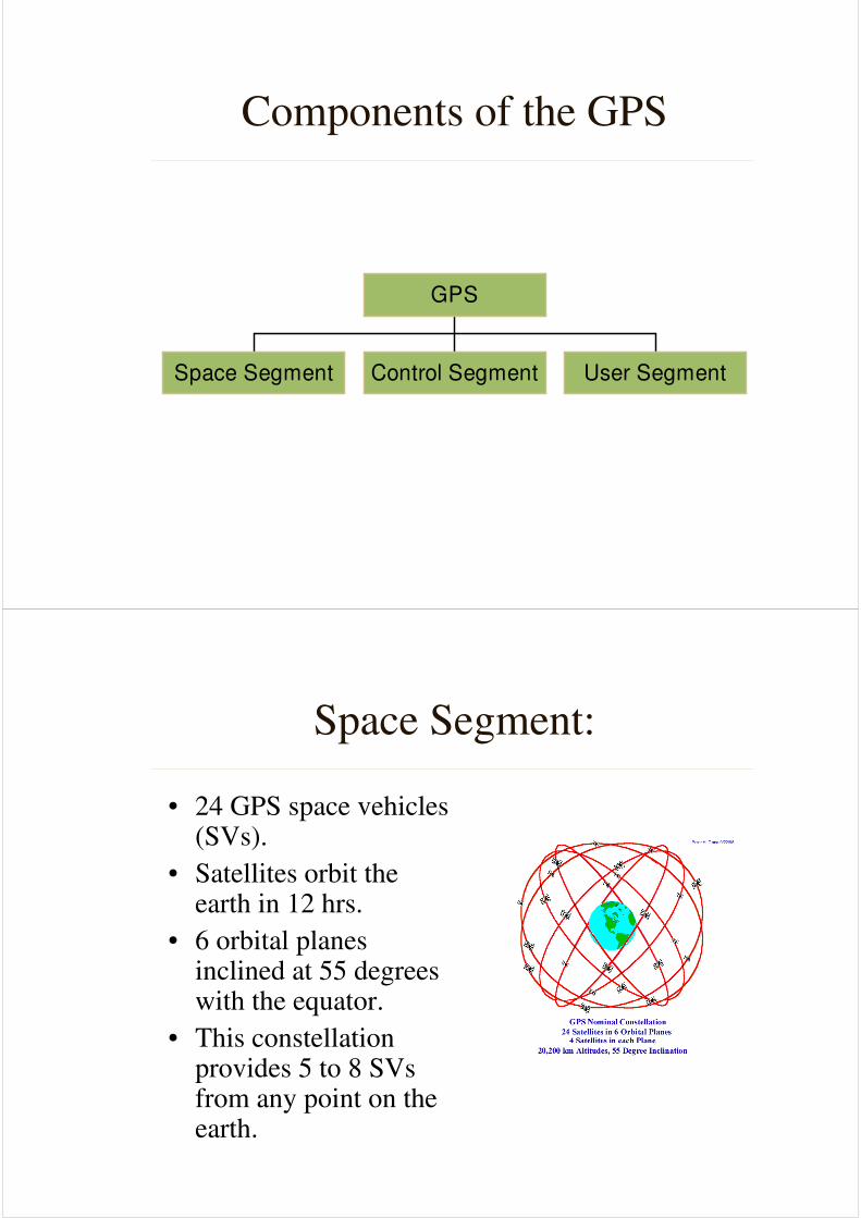
Components of the GPS
Space Segment Control Segment User Segment
GPS
Space Segment:
• 24 GPS space vehicles (SVs).
• Satellites orbit the earth in 12 hrs.
• 6 orbital planes inclined at 55 degrees with the equator.
• This constellation provides 5 to 8 SVsfrom any point on the earth.

Control Segment:
• The control segment comprises of 5 stations.
• They measure the distances of the overhead satellites every 1.5 seconds and send the corrected data to Master control.
• Here the satellite orbit, clock performance and health of the satellite are determined and determines whether repositioning is required.
• This information is sent to the three uplink stations
User Segment:
• It consists of receivers that decode the signals from the satellites.
• The receiver performs following tasks:
– Selecting one or more satellites
– Acquiring GPS signals
– Measuring and tracking
– Recovering navigation data
User Segment:
• There are two services SPS and PPS
• The Standard Positioning Service
– SPS- is position accuracy based on GPS
measurements on single L1 frequency C/A code
– C/A ( coarse /acquisition or clear/access) GPs
code sequence of 1023 pseudo random bi phase
modulation on L1 freq
User Segment:
• The Precise Position Service
– PPS is the highest level of dynamic positioning based on the dual freq P-code
– The P-code is a very long pseudo-random bi phase modulation on the GPS carrier which does not repeat for 267 days
– Only authorized users, this consists of SPS signal plus the P code on L1 and L2 and carrier phase measurement on L2
Cross Correlation
• Anti- spoofing denies the P code by mixing with a W-code to produce Y code which can be decoded only by user having a key.
• What about SPS users?
– They use cross correlation which uses the fact that the y code are the same on both frequencies
– By correlating the 2 incoming y codes on L1 and L2 the difference in time can be ascertained
– This delay is added to L1 and results in the pseudorange which contain the same info as the actual P code on L2
GPS Satellite Signal:
• L1 freq. (1575.42 Mhz) carries the SPS code and the navigation message.
• L2 freq. (1227.60 Mhz) used to measure ionosphere delays by PPS receivers
• 3 binary code shift L1 and/or L2 carrier phase
– The C/A code
– The P code
– The Navigation message which is a 50 Hz signal consisting of GPs satellite orbits . Clock correction and other system parameters
How does the GPS work?
• Requirements
• Triangulation from satellite
• Distance measurement through travel time of radio signals
• Very accurate timing required
• To measure distance the location of the satellite should also be known
• Finally delays have to be corrected
Triangulation
• Position is calculated
from distance
measurement
• Mathematically we
need four satellites
but three are sufficient
by rejecting the
ridiculous answer
Measuring Distance
• Distance to a satellite is determined by
measuring how long a radio signal takes to
reach us from the satellite
• Assuming the satellite and receiver clocks
are sync. The delay of the code in the
receiver multiplied by the speed of light
gives us the distance
Getting Perfect timing
• If the clocks are perfect sync the satellite
range will intersect at a single point.
• But if imperfect the four satellite will not
intersect at the same point.
• The receiver looks for a common
correction that will make all the satellite
intersect at the same point
Error Sources
• 95% due to hardware ,environment and
atmosphere
• Intentional signal degradation
– Selective availability
– Anti spoofing
Selective Availabity
• Two components
– Dither :
manipulation of the satellite clock freq
– Epsilon:
errors imposed within the ephemeris data sent
in the broadcast message
Anti spoofing
• Here the P code is made un gettable by
converting it into the Y code.
• This problem is over come by cross
correlation
Errors
• Satellite errors
– Errors in modeling clock offset
– Errors in Keplerian representation of ephemeris
– Latency in tracking
• Atmospheric propagation errors
– Through the ionosphere,carrier experiences phase advance and the code experiences group delay
• Dependent on
• Geomagnetic latitude
• Time of the day
• Elevation of the satellite
Errors
• Atmospheric errors can be removed by
– Dual freq measurement
low freq get refracted more than high freq
thus by comparing delays of L1 and L2 errors
can be eliminated
• Single freq users model the effects of the
ionosphere
Errors
• Troposphere causes delays in code and
carrier
But they aren’t freq dependent
But the errors are successfully modeled
• Errors due to Multipath
• Receiver noise

Errors
• Forces on the GPS satellite
– Earth is not a perfect sphere and hence uneven
gravitational potential distribution
– Other heavenly bodies attract the satellite,but these are
very well modeled
– Not a perfect vacuum hence drag but it is negligible at
GPS orbits
– Solar radiation effects which depends on the surface
reflectivity,luminosity of the sun,distance of to the
sun. this error is the largest unknown errors source
Errors due to geometry
• Poor GDOP
– When angles from the
receiver to the SVs
used are similar
• Good GDOP
– When the angles are
different
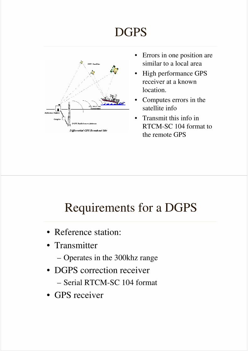
DGPS
• Errors in one position are
similar to a local area
• High performance GPS
receiver at a known
location.
• Computes errors in the
satellite info
• Transmit this info in
RTCM-SC 104 format to
the remote GPS
Requirements for a DGPS
• Reference station:
• Transmitter
– Operates in the 300khz range
• DGPS correction receiver
– Serial RTCM-SC 104 format
• GPS receiver
DGPS
• Data Links
– Land Links
• MF,LF,UHF/VHF freq used
• Radiolocations,local FM, cellular telephones and marine
radio beacons
– Satellite links
• DGPS corrections on the L band of geostaionary satellites
• Corrections are determined from a network of reference Base
stations which are monitored by control centers like
OmniSTAR and skyFix
RTCM-SC 104 format
• DGPS operators must follow the RTCM-SC 104 format
• 64 messages in which 21 are defined
• Type 1 contains pseudo ranges and range corrections,issue of data ephemeris (IODE)and user differential range error(URDE)
• The IODE allows the mobile station to identify the satellite navigation used by the reference station.
• UDRE is the differential error determined by the mobile station
DGPS
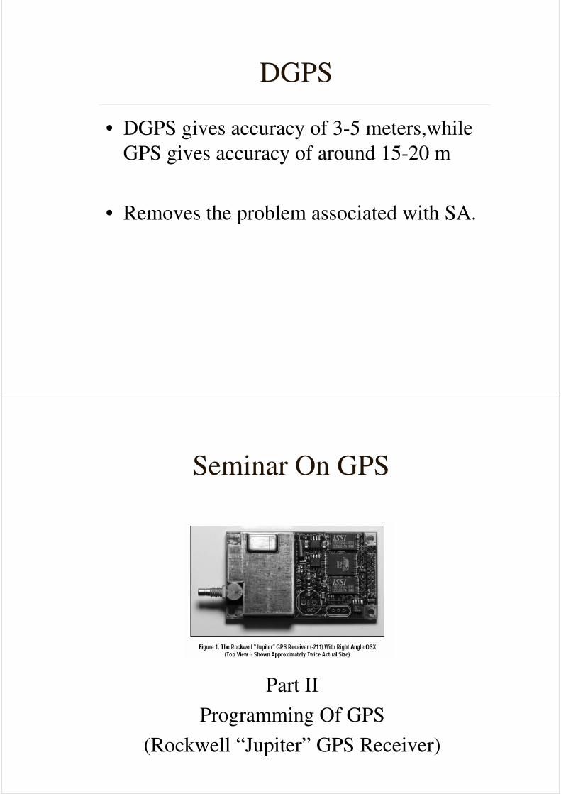
• DGPS gives accuracy of 3-5 meters,while
GPS gives accuracy of around 15-20 m
• Removes the problem associated with SA.
Seminar On GPS
Part II
Programming Of GPS
(Rockwell “Jupiter” GPS Receiver)
Features:• 12 parallel satellite tracking channels
• Supports NMEA-0183 data protocol & Binary data protocol.
• Direct, differential RTCM SC 104 data capability
• Static navigation improvements to minimize wander due to SA
• Active or Passive antenna to lower cost
• Max accuracy achievable by SPS
• Enhanced TTFF when in Keep –Alive power condition.
• Auto altitude hold mode from 3D to 2D navigation
• Maximum operational flexibility and configurable via user commands.
• Standard 2x10 I/O connector
• User selectable satellites
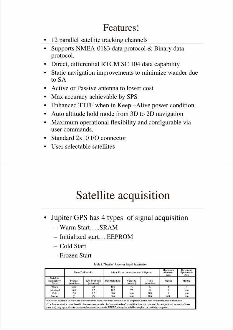
Satellite acquisition
• Jupiter GPS has 4 types of signal acquisition
– Warm Start…..SRAM
– Initialized start….EEPROM
– Cold Start
– Frozen Start

Navigation Modes
• 3D Navigation
– At least 4 satellites
– Computes latitude, longitude,altitude and time
• 2D Navigation
– Less than 4 satellites or fixed altitude is given
• DGPS Navigation
– Differential corrections are available through the
auxiliary serial port
– Must be in RTCM compliant
I/O interface of Jupiter
• Pins for powering GPS and Active antenna
• Two message formats NMEA and Binary
– Pin 7 should be made high or low accordingly
• Two serial port
– One is I/O….GPS data (Rx,Tx,Gnd)
– Only input….RTCM format differential
corrections (Rx,Gnd)
• Master reset pin(active low)
• Pin to provide battery backup
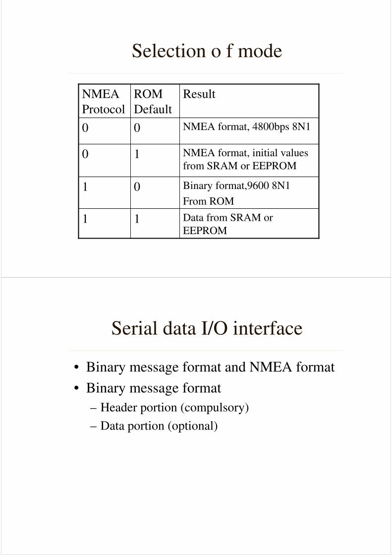
Selection o f mode
Data from SRAM or
EEPROM11
Binary format,9600 8N1
From ROM
01
NMEA format, initial values
from SRAM or EEPROM10
NMEA format, 4800bps 8N100
ResultROM
Default
NMEA
Protocol
Serial data I/O interface
• Binary message format and NMEA format
• Binary message format
– Header portion (compulsory)
– Data portion (optional)
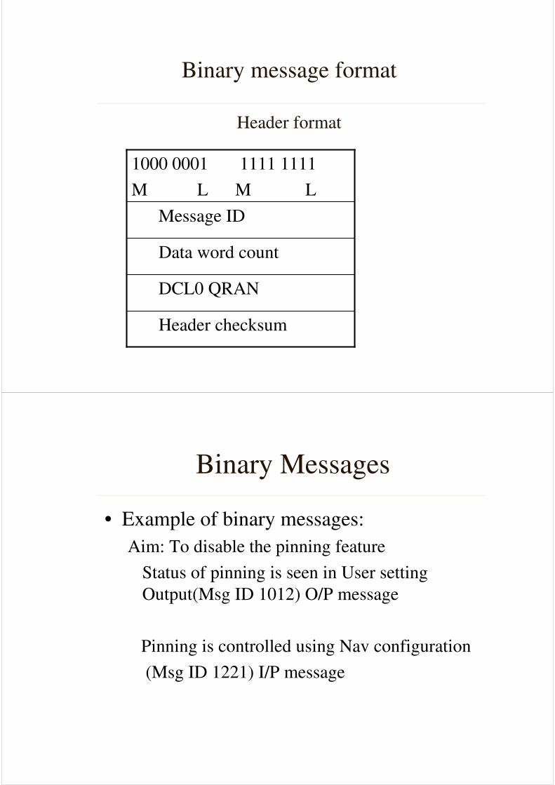
Binary message format
Header format
Header checksum
DCL0 QRAN
Data word count
Message ID
1000 0001 1111 1111
M L M L
Binary Messages
• Example of binary messages:
Aim: To disable the pinning feature
Status of pinning is seen in User setting
Output(Msg ID 1012) O/P message
Pinning is controlled using Nav configuration
(Msg ID 1221) I/P message
Binary messages
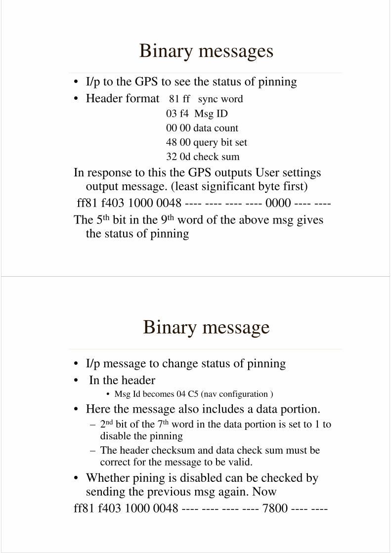
• I/p to the GPS to see the status of pinning
• Header format 81 ff sync word
03 f4 Msg ID
00 00 data count
48 00 query bit set
32 0d check sum
In response to this the GPS outputs User settings output message. (least significant byte first)
ff81 f403 1000 0048 ---- ---- ---- ---- 0000 ---- ----
The 5th bit in the 9th word of the above msg gives the status of pinning
Binary message
• I/p message to change status of pinning
• In the header • Msg Id becomes 04 C5 (nav configuration )
• Here the message also includes a data portion.
– 2nd bit of the 7th word in the data portion is set to 1 to disable the pinning
– The header checksum and data check sum must be correct for the message to be valid.
• Whether pining is disabled can be checked by sending the previous msg again. Now
ff81 f403 1000 0048 ---- ---- ---- ---- 7800 ---- ----
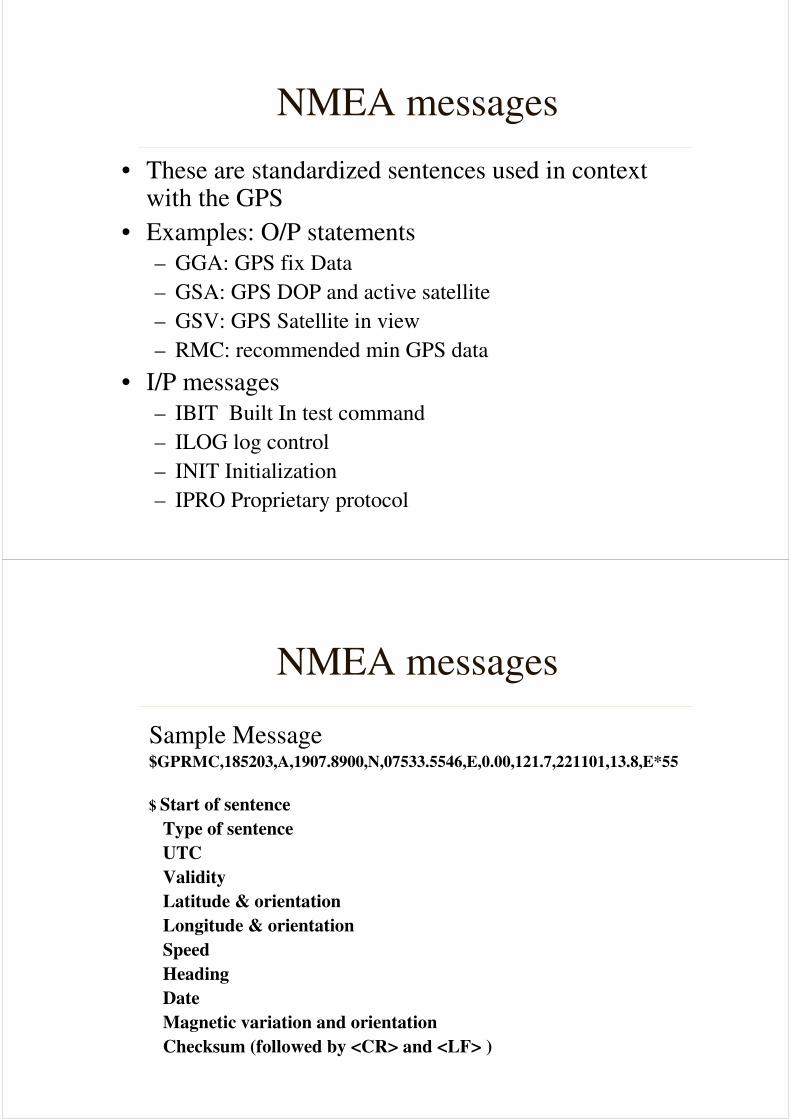
NMEA messages
• These are standardized sentences used in context with the GPS
• Examples: O/P statements
– GGA: GPS fix Data
– GSA: GPS DOP and active satellite
– GSV: GPS Satellite in view
– RMC: recommended min GPS data
• I/P messages
– IBIT Built In test command
– ILOG log control
– INIT Initialization
– IPRO Proprietary protocol
NMEA messages
Sample Message$GPRMC,185203,A,1907.8900,N,07533.5546,E,0.00,121.7,221101,13.8,E*55
$ Start of sentence
Type of sentence
UTC
Validity
Latitude & orientation
Longitude & orientation
Speed
Heading
Date
Magnetic variation and orientation
Checksum (followed by <CR> and <LF> )
Connections with the GPS
• The signals available at the serial pins of
the GPS are TTL level.
• To read the GPS output on Hyper terminal,
the TTL signal is converted into RS 232
using a Max 232 IC
• The input messages are sent to the GPS
using a simple C code
Conclusion:
• Components of the GPS
• Working of the GPS
• Errors sources in GPS
• Working of the DGPS
• Features of the Rockwell Jupiter GPS
• Binary and NMEA format
• Programming of the GPS