PART-I BASIC STRUCTURE OF A COMPUTER 1. … BASIC STRUCTURE OF A COMPUTER 1. Computer types...
31
UNIT-I COMPUTER ARCHITECTURE AND ORGANIZATION Blog - https://anilkumarprathipati.wordpress.com/ 1 PART-I BASIC STRUCTURE OF A COMPUTER 1. Computer types Classification of digital Computer based on size and Capability based on size and capability, computers are broadly classified into a. Microcomputers(Personal Computer) A microcomputer is the smallest general purpose processing system. The older pc started 8 bit processor with speed of 3.7MB and current pc 64 bit processor with speed of 4.66 GB. Examples: - IBM PCs, APPLE computers.Microcomputer can be classified into 2 types. 1. Desktops 2. Portables The difference is portables can be used while travelling whereas desktops computers cannot be carried around. The different portable computers are: - 1) Laptop 2) Notebooks 3) Palmtop (hand held) 4) Wearable computers Laptop: - this computer is similar to a desktop computers but the size is smaller. They are expensive than desktop. The weight of laptop is around 3 to 5 kg. Notebook:- These computers are as powerful as desktop but size of these computers are comparatively smaller than laptop and desktop. They weigh 2 to 3 kg. They are more costly than laptop. Palmtop (Hand held):- They are also called as personal Digital Assistant (PDA). These computers are small in size. They can be held in hands. These computers are not as powerful as desktop computers. Ex: - 3com palm-V. Wearable computer: - The size of this computer is very small so that it can be worn on the body. It has smaller processing power. For example pace maker to correct the heart beats. Insulin meters to find the level of insulin’s in the blood. b). Workstations:- It is used in large, high-resolution graphics screen built in network support, Engineering applications(CAD/CAM), software development desktop publishing Ex: Unix and windows NT. c) Minicomputer: - A minicomputer is a medium-sized computer. That is more powerful than a microcomputer. These computers are usually designed to serve multiple users simultaneously (Parallel Processing). They are more expensive than microcomputers.Ex: Digital Alpha, Sun Ultra.
-
Upload
doankhuong -
Category
Documents
-
view
215 -
download
1
Transcript of PART-I BASIC STRUCTURE OF A COMPUTER 1. … BASIC STRUCTURE OF A COMPUTER 1. Computer types...

UNIT-I COMPUTER ARCHITECTURE AND ORGANIZATION
Blog - https://anilkumarprathipati.wordpress.com/ 1
PART-I BASIC STRUCTURE OF A COMPUTER
1. Computer types Classification of digital Computer based on size and Capability based on size and capability,
computers are broadly classified into
a. Microcomputers(Personal Computer)
A microcomputer is the smallest general purpose processing system. The older pc started 8 bit
processor with speed of 3.7MB and current pc 64 bit processor with speed of 4.66
GB. Examples: - IBM PCs, APPLE computers.Microcomputer can be classified into 2
types. 1. Desktops
2. Portables
The difference is portables can be used while travelling whereas desktops computers cannot
be carried around.
The different portable computers are: -
1) Laptop
2) Notebooks
3) Palmtop (hand held)
4) Wearable computers
Laptop: - this computer is similar to a desktop
computers but the size is smaller. They are
expensive than desktop. The weight of laptop
is around 3 to 5 kg.
Notebook:- These computers are as
powerful as desktop but size of these
computers are comparatively smaller than
laptop and desktop. They weigh 2 to 3 kg.
They are more costly than laptop.
Palmtop (Hand held):- They are also
called as personal Digital Assistant (PDA).
These computers are small in size. They
can be held in hands. These computers are
not as powerful as desktop computers.
Ex: - 3com palm-V.
Wearable computer: - The size of this
computer is very small so that it can be
worn on the body. It has smaller
processing power. For example pace
maker to correct the heart beats. Insulin
meters to find the level of insulin’s in the
blood.
b). Workstations:- It is used in large, high-resolution graphics screen built in network
support, Engineering applications(CAD/CAM), software development desktop publishing
Ex: Unix and windows NT.
c) Minicomputer: - A minicomputer
is a medium-sized computer. That is more
powerful than a microcomputer. These
computers are usually designed to serve
multiple users simultaneously (Parallel
Processing). They are more expensive than
microcomputers.Ex: Digital Alpha, Sun
Ultra.

UNIT-I COMPUTER ARCHITECTURE AND ORGANIZATION
Blog - https://anilkumarprathipati.wordpress.com/ 2
d) Mainframe computers: - Computers with large storage capacities and very high speed of
processing (compared to mini- or microcomputers) are known as mainframe computers. They
support a large number of terminals for simultaneous use by a number of users like ATM
transactions. They are also used as central host computers in distributed data processing
system.Ex:- IBM 370, S/390.
e) Supercomputer: - Supercomputers have extremely large storage capacity and computing
speeds which are many times faster than other computers. A supercomputer is measured in terms
of tens of millions Instructions per second (MIPS), an operation is made up of numerous
instructions. The supercomputer is mainly used for large scale numerical problems in scientific
and engineering disciplines such as Weather analysis.Examples: - IBM Deep Blue.
2. Functional units
Functional Units A computer in its simplest form comprises five functional units namely input
unit, output unit memory unit, arithmetic & logic unit and control unit. Below figure depicts the
functional units of a computer system.
Let us discuss about each of them in brief:

UNIT-I COMPUTER ARCHITECTURE AND ORGANIZATION
Blog - https://anilkumarprathipati.wordpress.com/ 3
1. Input Unit: Computer accepts encoded information through input unit. The standard input
device is a keyboard. Whenever a key is pressed, keyboard controller sends the code to
CPU/Memory. Examples include Mouse, Joystick, Tracker ball, Light pen, Digitizer, Scanner
etc.
2. Memory Unit: Memory unit stores the program instructions (Code), data and results of
computations etc.
Memory unit is classified as:
• Primary /Main Memory.
• Secondary /AuxiliaryMemory.
Primary memory is a semiconductor memory that provides access at high speed. Run time
program instructions and operands are stored in the main memory. Main memory is classified
again as ROM and RAM. ROM holds system programs and firmware routines such as BIOS,
POST, I/O Drivers that are essential to manage the hardware of a computer. RAM is termed as
Read/Write memory or user memory that holds run time program instruction and data. While
primary storage is essential, it is volatile in nature and expensive.
Additional requirement of memory could be supplied as auxiliary memory at cheaper cost.
Secondary memories are non-volatile in nature.
Arithmetic and logic unit: ALU consist of necessary logic circuits like adder, comparator etc.,
to perform operations of addition, multiplication, comparison of two numbers etc.
Output Unit: Computer after computation returns the computed results, error messages, etc. via
output unit. The standard output device is a video monitor, LCD/TFT monitor. Other output
devices are printers, plotters etc.
Control Unit: Control unit co-ordinates activities of all units by issuing control signals. Control
signals issued by control unit govern the data transfers and then appropriate operations take place.
Control unit interprets or decides the operation/action to be performed.
The operations of a computer can be summarized as follows:
A set of instructions called a program reside in the main memory of computer.
The CPU fetches those instructions sequentially one-by-one from the main memory, decodes
them and performs the specified operation on associated data operands in ALU.
Processed data and results will be displayed on an output unit.
All activities pertaining to processing and data movement inside the computer machine are
governed by control unit.
3. Basic Operational Concepts of a Computer Most computer operations are executed in the ALU (arithmetic and logic unit) of a
processor.
Example: to add two numbers that are both located in memory.
– Each number is brought into the processor, and the actual addition is carried out by the
ALU.
– The sum then may be stored in memory or retained in the processor for immediate use.
Registers:
When operands are brought into the processor, they are stored in high-speed storage
elements (registers).
A register can store one piece of data (8-bit registers, 16-bit registers, 32-bit registers, 64-
bit registers, etc…)
Access times to registers are faster than access times to the fastest cache unit in the
memory hierarchy.
UNIT-I COMPUTER ARCHITECTURE AND ORGANIZATION
Blog - https://anilkumarprathipati.wordpress.com/ 4
Instructions:
Instructions for a processor are defined in the ISA (Instruction Set Architecture). Typical
instructions include:
– Mov BX, LocA
Fetch the instruction.
Fetch the contents of memory location LocA.
Store the contents in general purpose register BX.
– Add AX,BX
Fetch the instruction.
Add the contents of registers BX and AX.
Place the sum in register AX.
How are instructions sent between memory and the processor?
The program counter (PC) or instruction pointer (IP) contains the memory address of
the next instruction to be fetched and executed.
Send the address of the memory location to be accessed to the memory unit and
issue the appropriate control signals (memory read).
The instruction register (IR) holds the instruction that is currently being executed.
Timing is crucial and is handled by the control unit within the processor.
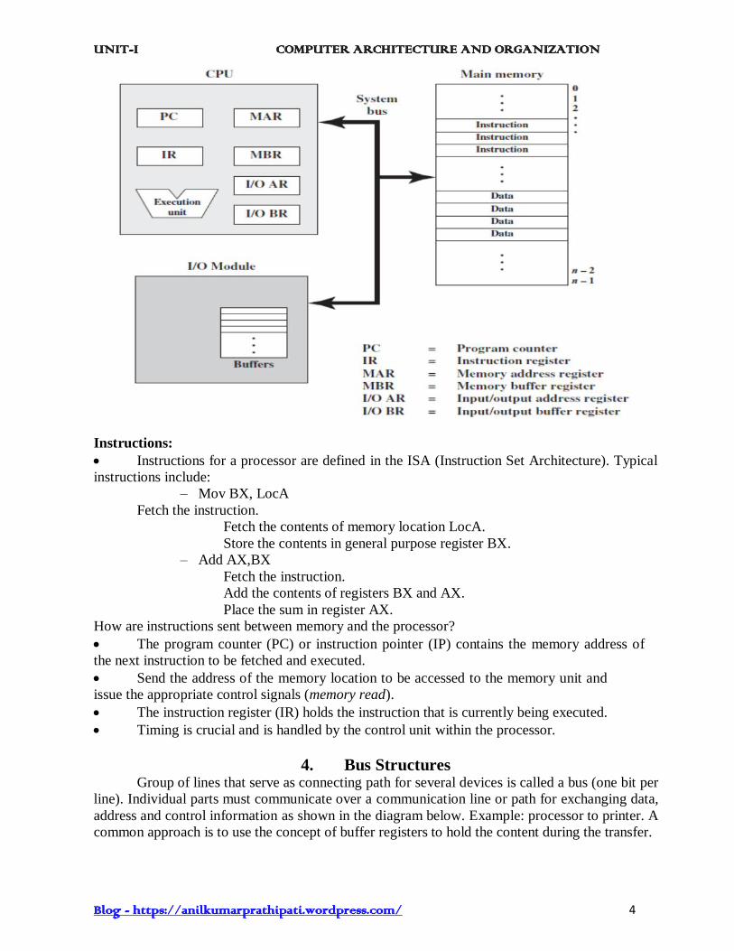
4. Bus Structures Group of lines that serve as connecting path for several devices is called a bus (one bit per
line). Individual parts must communicate over a communication line or path for exchanging data,
address and control information as shown in the diagram below. Example: processor to printer. A
common approach is to use the concept of buffer registers to hold the content during the transfer.

UNIT-I COMPUTER ARCHITECTURE AND ORGANIZATION
Blog - https://anilkumarprathipati.wordpress.com/ 5
Single Bus:
The data lines provide a path for moving data among system modules. These lines,
collectively, are called the data bus.
The address lines are used to designate the source or destination of the data on the data
bus. For example, if the processor wishes to read a word (8, 16, or 32 bits) of data from memory,
it puts the address of the desired word on the address lines.
The control lines are used to control the access to and the use of the data and address
lines. Control signals transmit both command and timing information among system modules.For
example, memory read, write, I/O read, write, Ack, grant, etc.
Timing signals indicate the validity of data and address information.
Command signals specify operations to be performed.
Multiple-bus:
If a great numbers of devices are connected to the bus, performance will suffer.Thereare
two main causes:
1. In general, the more devices attached to the bus, the greater the bus length and hence the
greater the propagation delay. These propagation delays can noticeably affect performance.
2. The bus may become a bottleneck as the aggregate data transfer demand approaches the
capacity of the bus. This is a race that a single bus is ultimately destined to lose.
Accordingly, most computer systems use multiple buses, generally laid out ina hierarchy. A
typical traditional structure is shown in figure.

UNIT-I COMPUTER ARCHITECTURE AND ORGANIZATION
Blog - https://anilkumarprathipati.wordpress.com/ 6
Elements of Bus Design:
5. Software
Computer software or just software is a general term used to describe the role that
computer programs, procedures and documentation play in a computer system.
Characteristics of Software:
Software is developed and engineered.
Software doesn't "wear-out".
Most software continues to be custom built.
Types of Software:
a. System software System software helps run the computer hardware and computer system. It includes a
combination of the following:
device drivers.
operating systems
servers
utilities
windowing systems
The purpose of systems software is to unburden the applications programmer from the often
complex details of the particular computer being used, including such accessories as

UNIT-I COMPUTER ARCHITECTURE AND ORGANIZATION
Blog - https://anilkumarprathipati.wordpress.com/ 7
communications devices, printers, device readers, displays and keyboards, and also to partition
the computer's resources such as memory and processor time in a safe and stable manner.
Examples are- Windows XP, Linux and Mac.
b. Programming software Programming software usually provides tools to assist a programmer in writing computer
programs, and software using different programming languages in a more convenient way. The
tools include:
compilers
debuggers
interpreters
linkers
text editors
c. Application software Application software allows end users to accomplish one or more specific (not directly computer
development related) tasks. Typical applications include:
industrial automation
business software
computer games
telecommunications (i.e., the internet and everything that flows on it)
databases
educational software
medical software
military software
molecular modelling software
spread-sheet
simulation software
Word processing
Application software exists for and has impacted a wide variety of topics.
6. Performance
It is the total time required to execute a program is the most important measure of performance
for a computer. Compiler, instruction set and hardware architecture, program all have impact on
performance.
Parameters which influence the performance are
•Clock speed.
•Type and number of instructions available.
•Average time required to execute an instruction.
•Memory access time.
•Power dissipation in the system.
•Number of I/O devices and types of I/O devices connected.
•The data transfer capacity of the bus.
Basic Performance Equation: basic performance equation is given by T = (N * S) / R, where
T=execution time, N=number of instructions, S=average cycles per instruction, R=clock rate in
cycles per second.

UNIT-I COMPUTER ARCHITECTURE AND ORGANIZATION
Blog - https://anilkumarprathipati.wordpress.com/ 8
7. Multiprocessors and Multi-computers Multicomputer- A computer made up of several computers. The term generally refers to
an architecture in which each processor has its own memory rather than multiple processors with
a shared memory.
Distributed computing deals with hardware and software systems containing more than
one processing element or storage element, concurrent processes or multiple processes,and
running under a loosely or tightly controlled regime.
A multicomputer may be considered to be either a loosely coupled NUMA computer or a
tightly coupled cluster. Multi computers are commonly used when strong computer power is
required in an environment with restricted physical space or electrical power. Common suppliers
include Mercury Computer Systems, CSPI, and SKY Computers. Common uses include 3D
medical imaging devices and mobile radar.
In distributed computing a program is split up into parts that run simultaneously on
multiple computers communicating over a network. Distributed computing is a form of parallel
computing, but parallel computing is most commonly used to describe program parts running
simultaneously on multiple processors in the same computer. Both types of processing require
dividing a program into parts that can run simultaneously, but distributed programs often must
deal with heterogeneous environments, network links of varying latencies, and unpredictable
failures in the network or the computers.
Multiprocessor- A multiprocessor system is simply a computer that has more than one
CPU on its motherboard. If the operating system is built to take advantage of this, it can run
different processes (or different threads belonging to the same process) on different CPUs.
Multiprocessing is the use of two or more central processing units (CPUs) within a single
computer system. The term also refers to the ability of a system to support more than one
processor and/or the ability to allocate tasks between them.
There are many variations on this basic theme, and the definition of multiprocessing can
vary with context, mostly as a function of how CPUs are defined (multiple cores on one die,
multiple chips in one package, multiple packages in one system unit, etc.).
8. Data Types Binary information in digital computers is stored in memory or processor registers.
Registers contain either data or control information. Control information is a bit or a group of bits
used to specify the sequence of command signals needed for manipulation of the data in other
registers. Data are numbers and other binary-coded information that are operated on, to achieve
required computational results.
The data types found in the registers of digital computers may be classified as being one
of the following categories: (1) numbers used in arithmetic computations, (2) letters of the
alphabet used in data processing, and (3) other discrete symbols used for specific purposes.
All types of data, except binary numbers, are represented in computer registers in binary-coded
form. This is because registers are made up of flip-flops and flip-flops are two-state devices that
can store only 1’s and 0’s. The binary number system is the most natural system to be used in a
digital computer. But sometimes it is convenient to employ different number systems, especially
the decimal number system, since it is used by people to perform arithmetic computations.
Number Systems:A number system of base, or radix, r is a system that uses distinct symbols
for r digits. Numbers are represented by a string of digit symbols. To determine the quantity that
the number represents, it is necessary to multiply each digit by an integer power of r and then
form the sum of all weighted digits. For example, the decimal number system in everyday use
employs the radix 10 system.
UNIT-I COMPUTER ARCHITECTURE AND ORGANIZATION
Blog - https://anilkumarprathipati.wordpress.com/ 9
The 10 symbols are 0, 1, 2, 3, 4, 5, 6, 7, 8, and 9. The string of digits 724.5 is interpreted
to represent the quantity. 7 x 10² + 2 x 101 + 4 x 100 + 5 x 10⁻¹ that is, 7 hundreds, plus 2 tens,
plus 4 units, plus 5 tenths. Every decimal number can be similarly interpreted to find the quantity
it represents.
To distinguish between different radix numbers, the digits will be enclosed in parentheses
and the radix of the number inserted as a subscript. For example, to show the equality between
decimal and binary forty-five we will write (101101)2 = (45)10. Besides the decimal and binary
number systems, the octal (radix 8) and hexadecimal (radix 16) are important in digital computer
work. The eight symbols of the octal system are 0, 1, 2, 3, 4, 5, 6, and 7. The 16 symbols of the
hexadecimal system are 0, 1, 2, 3, 4, 5, 6, 7, 8, 9, A, B, C, D, E, and F. The last six symbols are,
unfortunately, identical to the letters of the alphabet and can cause confusion at times. However,
this is the convention that has been adopted. When used to represent hexadecimal digits, the
symbols A, B, C, D, E, F correspond to the decimal numbers 10, 11, 12, 13, 14, 15, respectively.
Complements:Complements are used in digital computers for simplifying the subtraction
operation and for logical manipulation. There are two types of complements for each base r
system: the r’s complement and the (r-1)’s complement. When the value of the base r is
substituted in the name, the two types are referred to as the 2’s and 1’s complement for binary
numbers and the 10’s and 9’s complement for decimal numbers. (r-1)’s Complement: Given a
number N in base r having n digits, the (r-1)’s complement of N is defined as (rn – 1) – N. For
decimal numbers r = 10 and r – 1 = 9, so the 9’scomplement of N is (10n
– 1) – N.For example,
the 9’s complement of 546700 is 999999 – 546700 = 453299 and the 9’s complement of 12389 is
99999 –12389 = 87610.
(r’s) Complement: The r’s complement of an n digit number N in base r is defined as r n
– N for N ≠ 0. For example, the 10’s complement of 246700 is 753300 and is obtained by
leaving the two zeros unchanged, subtracting 7 from 10, and subtracting the other three digits
from 9.
Fixed-Point Representation:
Positive integers, including zero, can be represented as unsigned numbers. However, to
represent negative integers, we need a notation for negative values. In ordinary arithmetic, a
negative number is indicated by a minus sign and a positive number by a plus sign. Because of
hardware limitations, computers must represent everything with 1s and 0s, including the sign of a
number. As a consequence, it is customary to represent the sign with a bit placed in the leftmost
position of the number. The convention is to make the sign bit equal to 0 for positive and to 1 for
negative. In addition to the sign, a number may have a binary (or decimal) point. The position of
the binary point is needed to represent fractions, integers, or mixed integer-fraction numbers. The
representation of the binary point in a register is complicated by the fact that it is characterized by
a position in the register.
There are two ways of specifying the position of the binary point in a register: by giving it
a fixed position or by employing a floating-point representation. The fixed-point method assumes
that the binary point is always fixed in one position. The two positions most widely used are (1) a
binary point in the extreme left of the register to make the stored number a fraction, and (2) a
binary point in the extreme right of the register to make the stored number an integer. In either
case, the binary point is not actually present, but its presence is assumed from the fact that the
number stored in the register is treated as a fraction or as an integer. The floating-point
representation uses a second register to store a number that designates the position of the decimal
point in the first register.
Integer Representation:

UNIT-I COMPUTER ARCHITECTURE AND ORGANIZATION
Blog - https://anilkumarprathipati.wordpress.com/ 10
When an integer binary number is positive, the sign is represented by 0 and the magnitude
by a positive binary number. When the number is negative, the sign is represented by 1 but the
rest of the number may be represented in one of three possible ways:
1. Signed-magnitude representation
2. Signed-1’s complement representation
3. Signed-2’s complement representation
The signed-magnitude representation of a negative number consists of themagnitude and a
negative sign. In the other two representations, the negativenumber is represented in either the 1’s
or 2’s complement of its positive value. Asan example, consider the signed number 14 stored in
an 8-bit register. +14 isrepresented by a sign bit of 0 in the leftmost position followed by the
binaryequivalent of 14: 00001110. Note that each of the eight bits of the register musthave a
value and therefore 0’s must be inserted in the most significant positionsfollowing the sign bit.
Although there is only one way to represent +14, there arethree different waysto represent -14
with eight bits.
In signed-magnitude representation 1 0001110
In signed-1’s complement representation 1 1110001
In signed-2’s complement representation 1 1110010
The signed-magnitude representation of -14 is obtained from +14 bycomplementing only
the sign bit. The signed-1’s complement representation of -14is obtained by complementing all
the bits of +14, including the sign bit. The signed-2’s complement representation is obtained by
taking the 2’s complement of thepositive number, including its sign bit. The signed-magnitude
system is used inordinary arithmetic but is awkward when employed in computer arithmetic.
Therefore, the signed-complement is normally used. The 1’s complement imposesdifficulties
because it has two representations of 0 (+0 and -0). It is seldom used forarithmetic operations
except in some older computers. The 1’s complement is usefulas a logical operation since the
change of 1 to 0 or 0 to 1 is equivalent to a logicalcomplement operation.The following
discussion of signed binary arithmetic deals exclusively with thesigned-2’s complement
representation of negative numbers.
Floating-Point Representation:
The floating-point representation of a number has two parts. The first part represents
a signed, fixed-point number called the mantissa. The second part designates theposition of the
decimal (or binary) point and is called the exponent. The fixed-pointmantissa may be a fraction
or an integer. For example, the decimal number+6132.789 is represented in floating-point with a
fraction and an exponent as follows:
Fraction Exponent
+0.6132789 +04
The value of the exponent indicates that the actual position of the decimal point is
fourpositions to the right of the indicated decimal point in the fraction. This representationis
equivalent to the scientific notation +0.6132789 x 10+4
. Floating-point is alwaysinterpreted to
represent a number in the following form:m x re
Only the mantissa m and the exponent e are physically represented in the register
(including their signs). The radix r and the radix-point position of the mantissa arealways
assumed. The circuits that manipulate the floating-point numbers in registers conform with these
two assumptions in order to provide the correct computationalresults. A floating-point binary
number is represented in a similar manner except thatit uses base 2 for the exponent. For
example, the binary number +1001.11 isrepresented with an 8-bit fraction and 6-bit exponent as
follows: Fraction Exponent
01001110 000100

UNIT-I COMPUTER ARCHITECTURE AND ORGANIZATION
Blog - https://anilkumarprathipati.wordpress.com/ 11
The fraction has a 0 in the leftmost position to denote positive. The binary point of
thefraction follows the sign bit but is not shown in the register. The exponent has theequivalent
binary number +4. The floating-point number is equivalent tom x 2e=+(.1001110)2 x 2
+4
A floating-point number is said to be normalized if the most significant digit of
themantissa is nonzero. For example, the decimal number 350 is normalized but 00035 isnot.
Regardless of where the position of the radix point is assumed to be in themantissa, the number is
normalized only if its leftmost digit is nonzero. For example,the 8-bit binary number 00011010 is
not normalized because of the three leading 0s.
The number can be normalized by shifting it three positions to the left and discardingthe
leading 0s to obtain 11010000. The three shifts multiply the number by 23= 8. Tokeep the same
value for the floating-point number, the exponent must be subtracted by3. Normalized numbers
provide the maximum possible precision for the floating-pointnumber. A zero cannot be
normalized because it does not have a nonzero digit. It isusually represented in floating-point by
all 0s in the mantissa and exponent. Arithmeticoperations with floating-point numbers are more
complicated than arithmeticoperations with fixed-point numbers and their execution takes longer
and requires morecomplex hardware. However, floating-point representation is a must for
scientificcomputations because of the scaling problems involved with fixed-point computations.
Many computers and all electronic calculators have the built-in capability ofperforming floating-
point arithmetic operations. Computers that do not have hardwarefor floating-point computations
have a set of subroutines to help the user programscientific problems with floating-point
numbers.
9. Error Detection Codes Parity System is the simplest method for error detection.
- One parity bit attached to the information
- Even Parity and Odd Parity
Even Parity: One bit is attached to the information so that the total number of 1’sis even
number. 1011001 0
1010010 1
Odd Parity: One bit is attached to the information so that the total number of 1’sisodd number.
1011001 1
1010010 0
Parity Bit Generator: For b6b5... b0(7-bit information).
Even parity bit beven= b6 b5 ... b0
For odd parity bitbodd=beven 1.

UNIT-I COMPUTER ARCHITECTURE AND ORGANIZATION
Blog - https://anilkumarprathipati.wordpress.com/ 12
10. Addition and Subtraction of Unsigned Numbers The direct method of subtraction taught in elementary schools uses the borrowconcept. In
this method we borrow a 1 from a higher significant position when theminuend digit is smaller
than the corresponding subtrahend digit. This seems to beeasiest when people perform
subtraction with paper and pencil. When subtraction isimplemented with digital hardware, this
method is found to be less efficient than themethod that uses complements.
The subtraction of two n digit unsigned numbers M – N ( N ≠ 0) in base r can bedone as follows: 1. Add the minuend M to the r’s complement of the subtrahend N.
This performs M + (rn– N) = M – N + r
n.
2. If M ≥ N, the sum will produce an end carries rn, which is discarded, and whatis left is the
result M – N.
3. If M < N, the sum does not produce an end carry and is equal to rn–(N – M), which is the r’s
complement of (N – M). To obtain the answer in afamiliar form, take the r’s complement of the
sum and place a negative signin front.
Consider, for example, the subtraction 72532 – 13250 = 59282. The 10’scomplement of
13250 is 86750. Therefore:M = 72532. 10’s complement of N = +86750. Sum = 159282Discard
end carry, and the Answer = 59282
Since we are dealing with unsigned numbers, there is really no way to get anunsigned
result for the second example. When working with paper and pencil, werecognize that the answer
must be changed to a signed negative number. Whensubtracting with complements, the negative
answer is recognized by the absence ofthe end carry and the complemented result. Subtraction
with complements is donewith binary numbers in a similar manner using the same procedure
outlined above.Using the two binary numbers X = 1010100 and Y = 1000011, we perform
thesubtraction X – Y and Y – X using 2’s complements: X = 1010100. 2’s complement of Y =
+0111101, Sum = 10010001, Discard end carry 27 = -10000000. Answer: X – Y = 0010001
Y = 1000011
2’s complement of X = +0101100
Sum = 1101111
There is no end carry. Answer is negative 0010001 = 2’s complement of 1101111.
Addition and Subtraction With Signed –Magnitude Data:
We designate the magnitude of the two numbers by A and B. Where the signed numbers
are added or subtracted, we find that there are eight different conditions to consider, depending
on the sign of the numbers and the operation performed. Operation Add Magnitudes Subtract Magnitudes
When A > B When A < B When A = B
(+A) + (+B) +(A + B)
(+A) + (– B) + (A – B) – (B – A) + (A – B)
(– A) + (+ B) – (A – B) + (B – A) + (A – B)
(– A) + (– B) – (A + B)
(+ A) – (+ B) + (A - B) – (B – A) + (A – B)
(+ A) – (– B) + (A + B)
(–A) – (+B) – (A + B)
(–A) – (–B) – (A – B) + (B – A) + (A – B)
Table: Addition and Subtraction of Signed-Magnitude Numbers
UNIT-I COMPUTER ARCHITECTURE AND ORGANIZATION
Blog - https://anilkumarprathipati.wordpress.com/ 13
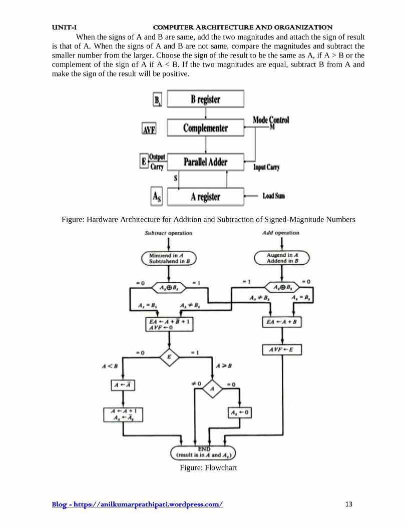
When the signs of A and B are same, add the two magnitudes and attach the sign of result
is that of A. When the signs of A and B are not same, compare the magnitudes and subtract the
smaller number from the larger. Choose the sign of the result to be the same as A, if A > B or the
complement of the sign of A if A < B. If the two magnitudes are equal, subtract B from A and
make the sign of the result will be positive.
Figure: Hardware Architecture for Addition and Subtraction of Signed-Magnitude Numbers
Figure: Flowchart

UNIT-I COMPUTER ARCHITECTURE AND ORGANIZATION
Blog - https://anilkumarprathipati.wordpress.com/ 14
11. Multiplication With Signed –2’s Complement Data:
Signed-Magnitude complements:
Multiplication of two fixed-point binary numbers in signed magnitude representation is
done with paper and pencil by a process of successive shift and adds operations. This process is
best illustrated with a numerical example:
This process looks at successive bits of the multiplier, least significant bit first. If the
multiplier bit is 1, the multiplicand is copied as it is; otherwise, we copy zeros. Now we shift
numbers copied down one position to the left from the previous numbers. Finally, the numbers
are added and their sum produces the product.
When multiplication is implemented in a digital computer, we change the process slightly.
Here, instead of providing registers to store and add simultaneously as many binary numbers as
there are bits in the multiplier, it is convenient to provide an adder for the summation of only two

UNIT-I COMPUTER ARCHITECTURE AND ORGANIZATION
Blog - https://anilkumarprathipati.wordpress.com/ 15
binary numbers, and successively accumulate the partial products in a register. Second, instead of
shifting the multiplicand to left, the partial product is shifted to the right, which results in leaving
the partial product and the multiplicand in the required relative positions. Now, when the
corresponding bit of the multiplier is 0, there is no need to add all zeros to the partial product
since it will not alter its value.
The hardware for multiplication consists of the equipment given in below Figure.
Multiplicand B = 10111 E A Q SC
Multiplier in Q 0 00000 10011 101
Qn = 1; add B 10111
First partial product 0 10111
Shift right EAQ 0 01011 11001 100
Qn = 1; add B 10111
Second partial product 1 00010
Shift right EAQ 1 00001 01100 011
Qn = 0; shift right EAQ 0 01000 10110 010
Qn = 0; shift right EAQ 0 00100 01011 001
Qn = 1; add B 10111
Fifth partial product 0 11011
Shift right EAQ 0 11011
Final product in AQ = 0110110101.
Table: Numerical Example for Binary Multiplier
UNIT-I COMPUTER ARCHITECTURE AND ORGANIZATION
Blog - https://anilkumarprathipati.wordpress.com/ 16
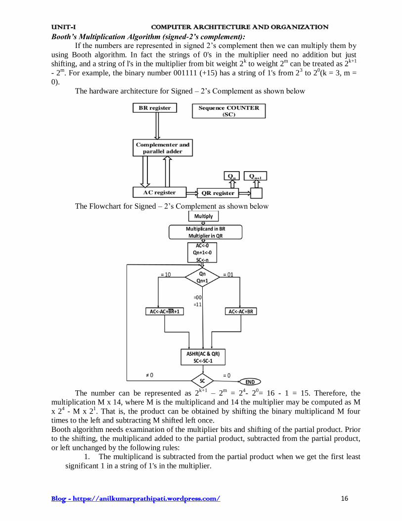
Booth’s Multiplication Algorithm (signed-2’s complement):
If the numbers are represented in signed 2’s complement then we can multiply them by
using Booth algorithm. In fact the strings of 0's in the multiplier need no addition but just
shifting, and a string of l's in the multiplier from bit weight 2k to weight 2
m can be treated as 2
k+1
- 2m. For example, the binary number 001111 (+15) has a string of 1's from 2
3 to 2
0(k = 3, m =
0).
The hardware architecture for Signed – 2’s Complement as shown below
The Flowchart for Signed – 2’s Complement as shown below
The number can be represented as 2
k+1 – 2
m = 2
4- 2
0= 16 - 1 = 15. Therefore, the
multiplication M x 14, where M is the multiplicand and 14 the multiplier may be computed as M
x 24 - M x 2
1. That is, the product can be obtained by shifting the binary multiplicand M four
times to the left and subtracting M shifted left once.
Booth algorithm needs examination of the multiplier bits and shifting of the partial product. Prior
to the shifting, the multiplicand added to the partial product, subtracted from the partial product,
or left unchanged by the following rules:
1. The multiplicand is subtracted from the partial product when we get the first least
significant 1 in a string of 1's in the multiplier.

UNIT-I COMPUTER ARCHITECTURE AND ORGANIZATION
Blog - https://anilkumarprathipati.wordpress.com/ 17
2. The multiplicand is added to the partial product when we get the first Q (provided
that there was a previous 1) in a string of 0's in the multiplier.
3. The partial product does not change when the multiplier bit is the same as the
previous multiplier bit.
The algorithm applies to both positive and negative multipliers in 2's complement
representation. This is because a negative multiplier ends with a string of l's and the last operation
will be a subtraction of the appropriate weight. For example, a multiplier equal to -14 is
represented in 2's complement as 110010 and is treated as -24 + 2
2 - 2
1 = -14.
A numerical example of Booth algorithm is given in Table for n = 5. It gives the
multiplication of (-9) x (-13) = +117.
BR = 10111
BR + 1 = 01001 AC QR Qn+1
SC
1 0 Initial 00000 10011 0 101
Subtract BR 01001
01001
ashr 00100 11001 1 100
1 1 ashr 00010 01100 1 011
0 1 Add BR 10111
11001
ashr 11100 10110 0 010
0 0 ashr 11110 01011 0 001
1 0 Subtract BR 01001
00111
ashr 0011 10101 1 000
Table: Example of Multiplication with Booth Algorithm
12. Division Algorithms Division of two fixed-point binary numbers in signed magnitude representation is
performed with paper and pencil by a process of successive compare, shift and subtract
operations. Binary division is much simpler than decimal division because here the quotient
digits are either 0 or 1 and there is no need to estimate how many times the dividend or partial
remainder fits into the divisor. The division process is described in Figure. The divisor B has five
bits and the dividend A had ten bits. Division: 11010 Quotient = Q B = 10001 0111000000 Dividend = A
01110 5 bits of A < B, quotient has 5 Bits 011100 6 bits of A VVB - 10001 Shift right B and subtract; enter 1 in Q
- 010110 - -10001 - - 001010 7 bits of remainder V B
- - - 010100 Shift right B and subtract; enter 1 in Q - - - -10001 - - - -000110 Remainder < B; enter 0 in Q; - - - - -00110 shift right B; Remainder V B
Shift right B and subtract; enter 1 in Q Remainder < B; enter 0 in Q Final remainder
Figure : Example of Binary Division

UNIT-I COMPUTER ARCHITECTURE AND ORGANIZATION
Blog - https://anilkumarprathipati.wordpress.com/ 18
The devisor is compared with the five most significant bits of the dividend. Since the 5-bit
number is smaller than B, we again repeat the same process. Now the 6-bit number is greater than
B, so we place a 1 for the quotient bit in the sixth position above the dividend. Now we shift
thedivisor once to the right and subtract it from the dividend. The difference is known as a partial
remainder because the division could have stopped here to obtain a quotient of 1 and a remainder
equal to the partial remainder. Comparing a partial remainder with the divisor continues the
process. If the partial remainder is greater than or equal to the divisor, the quotient bit is equal to
1. The divisor is then shifted right and subtracted from the partial remainder. If the partial
remainder is smaller than the divisor, the quotient bit is 0 and no subtraction is needed. The
divisor is shifted once to the right in any case. Obviously the result gives both a quotient and a
remainder.
Hardware Implementation for Signed-Magnitude Data
In hardware implementation for signed-magnitude data in a digital computer, it is
convenient to change the process slightly. Subtraction is achieved by adding A to the 2's
complement of B. End carry gives the information about the relative magnitudes.
Register EAQ is now shifted to the left with 0 inserted into Qn and the previous value of
E is lost. The example is given in Figure to clear the proposed division process. The divisor is
stored in the B register and the double-length dividend is stored in registers A and Q. The
dividend is shifted to the left and the divisor is subtracted by adding its 2's complement value. E
keeps the information about the relative magnitude. A quotient bit 1 is inserted into Qn and the
partial remainder is shifted to the left to repeat the process when E = 1. If E = 0, it signifies that A
< B so the quotient in Qn remains a 0 (inserted during the shift).
Figure: Example of Binary Division with Digital Hardware
UNIT-I COMPUTER ARCHITECTURE AND ORGANIZATION
Blog - https://anilkumarprathipati.wordpress.com/ 19
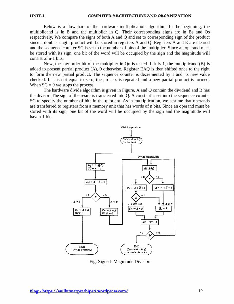
Below is a flowchart of the hardware multiplication algorithm. In the beginning, the
multiplicand is in B and the multiplier in Q. Their corresponding signs are in Bs and Qs
respectively. We compare the signs of both A and Q and set to corresponding sign of the product
since a double-length product will be stored in registers A and Q. Registers A and E are cleared
and the sequence counter SC is set to the number of bits of the multiplier. Since an operand must
be stored with its sign, one bit of the word will be occupied by the sign and the magnitude will
consist of n-1 bits.
Now, the low order bit of the multiplier in Qn is tested. If it is 1, the multiplicand (B) is
added to present partial product (A), 0 otherwise. Register EAQ is then shifted once to the right
to form the new partial product. The sequence counter is decremented by 1 and its new value
checked. If it is not equal to zero, the process is repeated and a new partial product is formed.
When SC = 0 we stops the process.
The hardware divide algorithm is given in Figure. A and Q contain the dividend and B has
the divisor. The sign of the result is transferred into Q. A constant is set into the sequence counter
SC to specify the number of bits in the quotient. As in multiplication, we assume that operands
are transferred to registers from a memory unit that has words of n bits. Since an operand must be
stored with its sign, one bit of the word will be occupied by the sign and the magnitude will
haven-1 bit.
Fig: Signed- Magnitude Division
UNIT-I COMPUTER ARCHITECTURE AND ORGANIZATION
Blog - https://anilkumarprathipati.wordpress.com/ 20
An overflow may occur in the division operation, which may be easy to handle if we
are using paper and pencil but is not easy when using hardware. This is because the length of
registers is finite and will not hold a number that exceeds the standard length. To see this, let us
consider a system that has 5-bit registers. We use one register to hold the divisor and two
registers to hold the dividend. From the example of Figure, the quotient will consist of six bits
if the five most significant bits of the dividend constitute a number greater than the divisor. The
quotient is to be stored in a standard 5-bit register, so the overflow bit will require one more
flip-flop for storing the sixth bit. This divide-overflow condition must be avoided in normal
computer operations because the entire quotient will be too long for transfer into a memory unit
that has words of standard length, that is, the same as the length of registers. Provisions to
ensure that this condition is detected must be included in either the hardware or the software of
the computer, or in a combination of the two.
When the dividend is twice as long as the divisor, we can understand the condition for
overflow as follows:
A divide-overflow occurs if the high-order half bits of the dividend makes a number
greater than or equal to the divisor. Another problem associated with division is the fact that a
division by zero must be avoided. The divide-overflow condition takes care of this condition as
well. This occurs because any dividend will be greater than or equal to a divisor, which is equal
to zero. Overflow condition is usually detected when a special flip-flop is set. We will call it a
divide-overflow flip-flop and label it DVF.
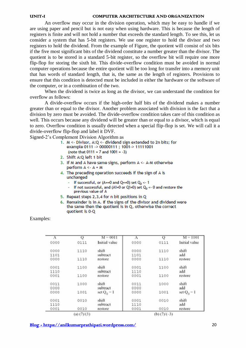
Signed-2’s Complement Division Algorithm as
Examples:

UNIT-I COMPUTER ARCHITECTURE AND ORGANIZATION
Blog - https://anilkumarprathipati.wordpress.com/ 21
13. Floating-point Arithmetic operations
In many high-level programming languages we have a facility for specifying floating-
point numbers. The most common way is by a real declaration statement. High level
programming languages must have a provision for handling floating-point arithmetic
operations. The operations are generally built in the internal hardware. If no hardware is
available, the compiler must be designed with a package of floating-point software subroutine.
Although the hardware method is more expensive, it is much more efficient than the software
method. Therefore, floating- point hardware is included in most computers and is omitted only
in very small ones.
Basic Considerations: There are two part of a floating-point number in a computer - a
mantissa m and an exponent e. The two parts represent a number generated from multiplying m
times a radix r raised to the value of e. Thus m x re
The mantissa may be a fraction or an integer. The position of the radix point and the value of
the radix r are not included in the registers. For example, assume a fraction representation and a
radix 10. The decimal number 537.25 is represented in a register with m = 53725 and e = 3 and
is interpreted to represent the floating-point number
.53725 x 103
A floating-point number is said to be normalized if the most significant digit of the
mantissa in nonzero. Biased exponents have the advantage that they contain only positive
numbers. Now it becomes simpler to compare their relative magnitude without bothering about
their signs. Another advantage is that the smallest possible biased exponent contains all zeros.
The floating-point representation of zero is then a zero mantissa and the smallest possible
exponent.
Register Configuration: The register configuration for floating-point operations is shown in
figure. As a rule, the same registers and adder used for fixed-point arithmetic are used for
processing the mantissas. The difference lies in the way the exponents are handled.
The register organization for floating-point operations is shown in Fig. Three registers are
there, BR, AC, and QR. Each register is subdivided into two parts. The mantissa part has the
same uppercase letter symbols as in fixed-point representation. The exponent part may use
corresponding lower-case letter symbol.
Figure: Registers for Floating Point arithmetic
operations

UNIT-I COMPUTER ARCHITECTURE AND ORGANIZATION
Blog - https://anilkumarprathipati.wordpress.com/ 22
The AC has a mantissa whose sign is in As, and a magnitude that is in A. The diagram
shows the most significant bit of A, labelled by A1. The bit in his position must be a 1 to
normalize the number. Note that the symbol AC represents the entire register, that is, the
concatenation of As, A and a.
In the similar way, register BR is subdivided into Bs, B, and b and QR into Qs, Q and q.
A parallel-adder adds the two mantissas and loads the sum into A and the carry into E. A
separate parallel adder can be used for the exponents. The exponents do not have a district sign
bit because they are biased but are represented as a biased positive quantity. It is assumed that
the floating-point numbers are so large that the chance of an exponent overflow is very remote
and so the exponent overflow will be neglected. The exponents are also connected to a
magnitude comparator that provides three binary outputs to indicate their relative magnitude.
The number in the mantissa will be taken as a fraction, so they binary point is assumed
to reside to the left of the magnitude part. Integer representation for floating point causes
certain scaling problems during multiplication and division. To avoid these problems, we adopt
a fraction representation.
The numbers in the registers should initially be normalized. After each arithmetic
operation, the result will be normalized. Thus all floating-point operands are always
normalized.
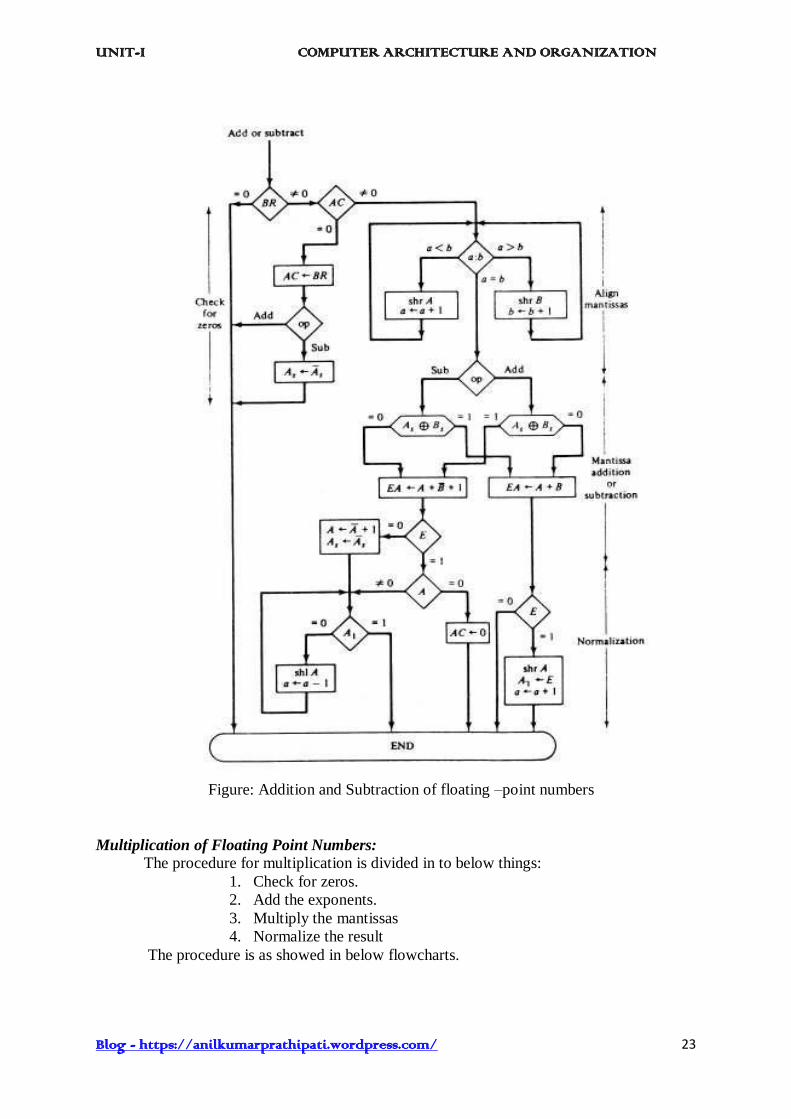
Addition and Subtraction of Floating Point Numbers: During addition or subtraction, the two
floating-point operands are kept in AC and BR. The sum or difference is formed in the AC.
The algorithm can be divided into four consecutive parts:
1. Check for zeros.
2. Align the mantissas.
3. Add or subtract the mantissas
4. Normalize the result
A floating-point number cannot be normalized, if it is 0. If this number is used for
computation, the result may also be zero. Instead of checking for zeros during the
normalization process we check for zeros at the beginning and terminate the process if
necessary. The alignment of the mantissas must be carried out prior to their operation. After the
mantissas are added or subtracted, the result may be un-normalized. The normalization
procedure ensures that the result is normalized before it is transferred to memory.
For adding or subtracting two floating-point binary numbers, if BR is equal to zero, the
operation is stopped, with the value in the AC being the result. If AC = 0, we transfer the
content of BR into AC and also complement its sign we have to subtract the numbers. If neither
number is equal it to zero, we proceed to align the mantissas.
The addition and subtraction of the two mantissas is similar to the fixed-point addition
and subtraction algorithm presented in Fig. The magnitude part is added or subtracted depends
on the operation and the signs of the two mantissas. If an overflow occurs when the magnitudes
are added, it is transferred into flip-flop E. If E = 1, the bit is transferred into A1 and all other
bits of A are shifted right. The exponent must be incremented so that it can maintain the correct
number.
If the magnitudes were subtracted, there may be zero or may have an underflow in the
result. If the mantissa is equal to zero the entire floating-point number in the AC is cleared to
zero. Otherwise, the mantissa must have at least one bit that is equal to 1. The mantissa has an
underflow if the most significant bit in position A1, is 0. In that case, the mantissa is shifted left
and the exponent decremented. The bit in A1 is checked again and the process is repeated until
A1 = 1. When A1 = 1, the mantissa is normalized and the operation is completed.
UNIT-I COMPUTER ARCHITECTURE AND ORGANIZATION
Blog - https://anilkumarprathipati.wordpress.com/ 23
Figure: Addition and Subtraction of floating –point numbers
Multiplication of Floating Point Numbers:
The procedure for multiplication is divided in to below things:
1. Check for zeros.
2. Add the exponents.
3. Multiply the mantissas
4. Normalize the result
The procedure is as showed in below flowcharts.

UNIT-I COMPUTER ARCHITECTURE AND ORGANIZATION
Blog - https://anilkumarprathipati.wordpress.com/ 24
Fig: Flowchart for floating-point multiplication
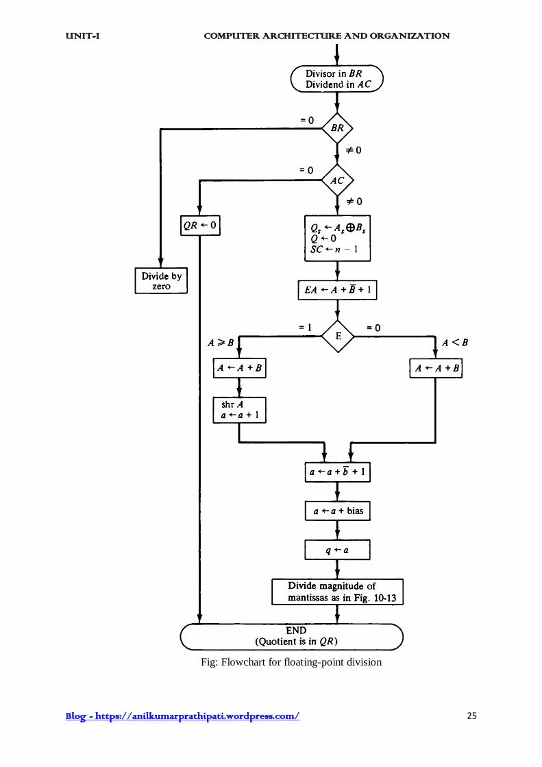
Division of Floating Point Numbers:
The procedure for division is divided in to below things:
1. Check for zeros.
2. Subtract the exponents.
3. Divide the mantissas
4. Normalize the result
The procedure is as showed in below flowcharts.
UNIT-I COMPUTER ARCHITECTURE AND ORGANIZATION
Blog - https://anilkumarprathipati.wordpress.com/ 25
Fig: Flowchart for floating-point division

UNIT-I COMPUTER ARCHITECTURE AND ORGANIZATION
Blog - https://anilkumarprathipati.wordpress.com/ 26
14. Decimal Arithmetic operations The user of a computer input data in decimal numbers and receives output in decimal
form. But a CPU with an ALU can perform arithmetic micro-operations only on binary data.
To perform arithmetic operations with decimal data, it is necessary to convert the input decimal
numbers to binary, to perform all calculations with binary numbers, and to convert the results
into decimal. This may be an efficient method in applications requiring a large number of
calculations and a relatively smaller amount of input and output data. When the application
calls for a large amount of input-output and a relatively smaller number of arithmetic
calculations, it becomes convenient to do the internal arithmetic directly with the decimal
numbers. Computers that can do decimal arithmetic must store the decimal data in binary
coded form. The decimal numbers are then applied to a decimal arithmetic unit, which can
execute decimal arithmetic micro-operations.
BCD Adder:
Now let us see the arithmetic addition of two decimal digits in BCD, with a possible
carry from a previous stage. Since each input digit does not exceed 9, the output sum cannot be
greater than 9 + 9 + 1 = 19, the 1 in the sum being an input-carry. Assume that we apply two
BCD digits to a 4-bit binary adder. The adder will form the sum in binary and produce a result
that may range from 0 to 19. These binary numbers are listed in Table and are labeled by
symbols K, Z8, Z4, Z2, and Z1. K is the carry and the subscripts under the letter Z represent
the weights 8, 4, 2, and 1 that can be assigned to the four its in the BCD code. The first column
in the table lists the binary sums as they appear in the outputs of a 4-bit binary adder.
The output sum of two decimal numbers must be represented in BCD and should appear in the
form listed in the second column of the table. The problem is to find a simple rule by which the
binary column of the table. The problem is to find a simple rule so that the binary number in
the first column can be converted to the correct BCD digit representation of the number in the
second column.
It is apparent that when the binary sum is equal to or less than 1001, no conversion is
needed. When the binary sum is greater than 1001, we need to add of binary 6 (0110) to the
binary sum to find the correct BCD representation and to produces output-carry as required.
Table : Derivation of BCD Adder
One way of adding decimal numbers in BCD is to use one 4-bit binary adder and
UNIT-I COMPUTER ARCHITECTURE AND ORGANIZATION
Blog - https://anilkumarprathipati.wordpress.com/ 27
perform the arithmetic operation one digit at a time. The low-order pair of BCD digits is first
added to produce a binary sum if the result is equal or greater than 1010, it is corrected by
adding 0110 to the binary sum. The second operation produces an output-carry for the next pair
of significant digits. The next higher-order pair of digits, together with the input-carry, is then
added to produce their binary sum. If this result is equal to or greater than 1010,then it is
corrected by adding 0110. The procedure is repeated until all decimal digits are added.
The logic circuit that detects the necessary correction can be derived from the table entries. It is
obvious that a correction is needed when the binary sum has an output carry K = 1. The other
six combinations from 1010 to 1111 that need a correction have a 1 in position Z8. To
differentiate them from binary 1000 and 1001, which also have a 1 in position Z8, we specify
further that either Z4 or Z2 must have a 1. The condition for a correction and an output-carry
can be expressed by the Boolean function
C = K + Z8 Z4 + Z8 Z2
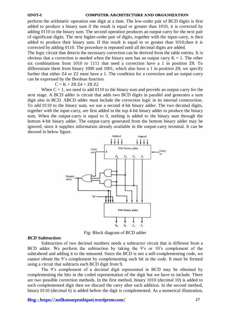
When C = 1, we need to add 0110 to the binary sum and provide an output-carry for the
next stage. A BCD adder is circuit that adds two BCD digits in parallel and generates a sum
digit also in BCD. ABCD adder must include the correction logic in its internal construction.
To add 0110 to the binary sum, we use a second 4-bit binary adder. The two decimal digits,
together with the input-carry, are first added in the top 4-bit binary adder to produce the binary
sum. When the output-carry is equal to 0, nothing is added to the binary sum through the
bottom 4-bit binary adder. The output-carry generated from the bottom binary adder may be
ignored, since it supplies information already available in the output-carry terminal. It can be
showed in below figure.
Fig: Block diagram of BCD adder
BCD Subtraction:
Subtraction of two decimal numbers needs a subtractor circuit that is different from a
BCD adder. We perform the subtraction by taking the 9’s or 10’s complement of the
subtrahend and adding it to the minuend. Since the BCD is not a self-complementing code, we
cannot obtain the 9’s complement by complementing each bit in the code. It must be formed
using a circuit that subtracts each BCD digit from 9.
The 9’s complement of a decimal digit represented in BCD may be obtained by
complementing the bits in the coded representation of the digit but we have to include. There
are two possible correction methods. In the first method, binary 1010 (decimal 10) is added to
each complemented digit then we discard the carry after each addition. In the second method,
binary 0110 (decimal 6) is added before the digit is complemented. As a numerical illustration,
UNIT-I COMPUTER ARCHITECTURE AND ORGANIZATION
Blog - https://anilkumarprathipati.wordpress.com/ 28
the 9’s complement of BCD 0111(decimal 7) is computed by first complementing each bit to
obtain 1000. Adding binary 1010 and discarding the carry, we obtain 0010 (decimal 2). By the
second method, we add 0110 to 0111 to obtain 1101. Complementing each bit, we obtain the
required result of 0010. Complementing each bit of 4-bit binary number N is identical to the
subtraction of the number from 1111 (decimal 15). Adding the binary equivalent of decimal 10
gives 15 – N + 10 = 9 + 16. But 16 signifies the carry that is discarded, so the result is 9 – N as
required. Adding the binary equivalent of decimal 6 and then complementing gives 15 – (N +
6) = 9 – N as required.
We can also obtain the 9’s complement of a BCD digit through a combinational circuit.
When this circuit is combined to a BCD adder, we get a BCD adder/subtractor. Let the
subtrahend (or addend) digit be denoted by the four binary variables B8, B4, B2, and B1. Let
M be a mode bit that controls the add/subtract operation. When M = 0, the two digits are
added; when M = 1, the digits are subtracted. Let the binary variables x8, x4, x2, and x1 be the
outputs of the 9’s complement circuit. By an examination of the truth table for the circuit, it
may be observed that B1 should always be complemented; B2 is always the same in the 9’s
complement as in the original digit; x4 is 1 when the exclusive OR of B2 and B4 is 1; and x8 is
1 when B8B4B2 = 000. The Boolean functions for the 9’s complement circuit are
x1 = B1 M’ + B’1 M x2 = B2
x4 = B4M’ + (B’4B2 + B4B’2)M x8 = B8M’ + B’8B4’B’2M
From these equations we see that x = B when M = 0. When M = 1, the x equals to the
9’s complement of B.
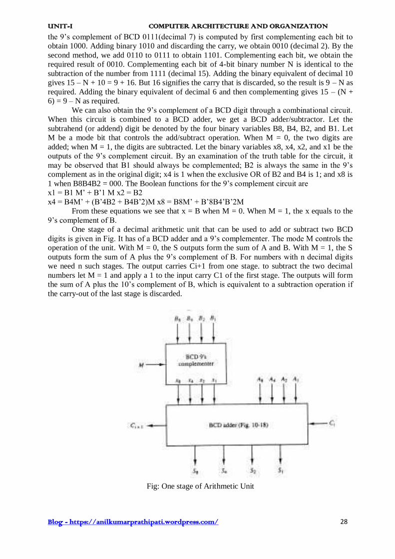
One stage of a decimal arithmetic unit that can be used to add or subtract two BCD
digits is given in Fig. It has of a BCD adder and a 9’s complementer. The mode M controls the
operation of the unit. With M = 0, the S outputs form the sum of A and B. With M = 1, the S
outputs form the sum of A plus the 9’s complement of B. For numbers with n decimal digits
we need n such stages. The output carries Ci+1 from one stage. to subtract the two decimal
numbers let M = 1 and apply a 1 to the input carry C1 of the first stage. The outputs will form
the sum of A plus the 10’s complement of B, which is equivalent to a subtraction operation if
the carry-out of the last stage is discarded.
Fig: One stage of Arithmetic Unit

UNIT-I COMPUTER ARCHITECTURE AND ORGANIZATION
Blog - https://anilkumarprathipati.wordpress.com/ 29
The below figures show the possibilities of Addition with respect of Decimal and bits.
Fig: Decimal Arithmetic adders

UNIT-I COMPUTER ARCHITECTURE AND ORGANIZATION
Blog - https://anilkumarprathipati.wordpress.com/ 30
Where A,B,Q are the Register,
Ae, Be, are Extension
decimals, QLis the Last
decimal in Q register.
Fig: Registers for Decimal Arithmetic Multiplication and Division
Fig: Flowchart Decimal Arithmetic Multiplication

UNIT-I COMPUTER ARCHITECTURE AND ORGANIZATION
Blog - https://anilkumarprathipati.wordpress.com/ 31
Fig: Flowchart Decimal Arithmetic Division