part Design Preface - Catiacatia.com.pl/tutorial/z2/part_design.pdf · Preface The CATIA Version 5...
244
Part Design Preface What's New ? Getting Started Basic Tasks Advanced Tasks Workbench Description Customizing Glossary Index © Dassault Systèmes 1994-99. All rights reserved.
Transcript of part Design Preface - Catiacatia.com.pl/tutorial/z2/part_design.pdf · Preface The CATIA Version 5...

Part Design
Preface
What's New ?
Getting Started
Basic Tasks Advanced Tasks
Workbench Description
Customizing
Glossary
Index
© Dassault Systèmes 1994-99. All rights reserved.

PrefaceThe CATIA Version 5 Part Design application makes it possible to design precise 3Dmechanical parts with an intuitive and flexible user interface, from sketching in anassembly context to iterative detailed design. CATIA Version 5 Part Designapplication will enable you to accommodate design requirements for parts of variouscomplexities, from simple to advanced.
This new application, which combines the power of feature-based design with theflexibility of a Boolean approach, offers a highly productive and intuitive designenvironment with multiple design methodologies, such as post-design and local 3Dparameterization.
As a scalable product, CATIA Version 5 Part Design can be used in cooperation withother current or future companion products in the next CATIA generation such asCATIA Version 5 Assembly Design and CATIA Version 5 Generative Drafting. Thewidest application portfolio in the industry is also accessible through interoperabilitywith CATIA Solutions Version 4 to enable support of the full product developmentprocess from initial concept to product in operation.
The Part Design User's Guide has been designed to show you how to create a part.There are several ways of creating a part and this book aims at illustrating the severalstages of creation you may encounter.

About This ProductThis book is intended for the user who needs to become quickly familiar withCATIA-Part Design Version 5 Release 3 product. The user should be familiar withbasic CATIA Version 5 concepts such as document windows, standard and viewtoolbars.
To get the most out of this guide, we suggest you start reading and performing thestep-by-step tutorial Getting Started. This tutorial will show you how to create a basicpart from scratch.
The next sections deal with the handling of CATPart data, then the creation andmodification of various types of features you will need to construct parts. This guidealso presents other Part Design capabilities allowing you to design complex parts. Youmay also want to take a look at the sections describing the Part Design menus andtoolbars at the end of the guide.

Where to Find More InformationPrior to reading this book, we recommend that you read the CATIA- InfrastructureUser's guide Version 5 and CATIA-Dynamic Sketcher User's Guide Version 5.
The CATIA- Assembly Design User's Guide Version 5 and the CATIA Wireframe andSurface User's Guide may prove useful too.

What's New?General
New task: Draft analysisNew task: Curvature analysisEnhanced: UpdateEnhanced: Replace
FeaturesNew task: LoftNew task: Remove lofted materialEnhanced: DraftEnhanced: Pocket, holeEnhanced: Rectangular pattern, circular pattern, user patternEnhanced: Variable radius fillet

Getting StartedBefore getting into the detailed instructions for using CATIA Version 5 Part Design,the following tutorial aims at giving you a feel as to what you can do with the product. Itprovides a step-by-step scenario showing you how to use key functionalities.
The main tasks described in this section are:
All together, the tasks should take about ten minutes tocomplete.
The final part will look like this:
Now, let's get to sketching the profile!

Entering the Part Design WorkbenchThis first task shows you how to enter the Part Design workbench.
1. Select the File -> New commands (or click the New icon).
The New dialog box is displayed, allowing you to choose the type of document you need.
2. Select Part in the List of Types field and click OK.
The Part Design workbench is loaded and an empty CATPart document opens.
The commands for creating and editing features are available in the workbench toolbar. Now, let's perform thefollowing task Sketching a Profileto see the Sketcher workbench.


Sketching a Profile
In this task you will learn how to:enter the Sketcher workbenchcreate the profile which you will later extrude to create a pad
1. Click the Sketcher icon to start the Sketcher workbench.
2. Select xy plane to define the sketch plane.
Now, the Sketcher workbench is displayed. It contains the tools you need to sketch any profile.
The Select command is the default Sketcher mode.

The grid you can see has been designed to make your sketch easier to do. You can redefine the grid of yourchoice or simply hide it using the Tools -> Options... Sketcher tab command.
Before starting, we recommend to zoom out . Now, start to sketch your profile.
3. Click the Profile icon . Activating this command displays three options in the Tools toolbar. The Line
command is activated by default.
4. First, create a line: click a point, drag the cursor and click a second point to end your first line.
CATIA uses a green symbol to call your attention on the line property. This line is horizontal.
5. Click at the points as shown to sketch two additional lines:
CATIA uses another green symbol to mention that the second line you created is vertical.
6. To end the profile, click at the starting point.
The profile now looks like this:

7. To complete the profile shape, create two arcs tangent to two lines: click the Corner icon . Activating
this command displays the Corner toolbar which contains three options. The Corner trim all command is activated by default.8. Select both lines as indicated.
The lines are then joined by a rounded corner which moves as you move the cursor.9. Click in the area as shown to define the first corner:
Your first corner is created. Do not be concerned about the radius value. You will modify it later.

10. Now, click anywhere outside the sketch to unselect the corner and repeat the operation to create asecond corner at the bottom of the profile.
You should obtain this:
The alternative method for creating a corner consists in selecting the intersection point between the two linesinstead of selecting both lines.
11. Now, set a dimension between two lines. First, multiselect the lines as indicated.

12. Click the Constraint icon .
This command sets a length constraint. The distance between the lines you have selected is 200 mm.13. Click anywhere to locate the dimension.
14. Now, double-click the radius value of the first corner.
The Constraint Edition dialog box is displayed.
15. Enter 45mm in the Value field to edit the corner radius.

16. Click OK to confirm the operation.
17. Repeat the operation to edit the second corner. Enter 53mm.
Eventually, your profile looks like this:
When performing this task, you may have noticed that CATIA never required you to update youroperations. Actually, whatever operations you are accomplishing in the Sketcher, the applicationautomatically updates the geometry.
Now, you are going to quit the Sketcher workbench to continue the rest of the scenario.

Creating a PadNow that you have sketched your profile, you can create a pad. This task willshow you how to:
return to the 3D worldcreate a pad, that is extrude the profile.
If you have not performed the previous task, open the GS_sketch1.CATPartdocument from the GSsamples/part_design directory.
1.Click the Exit Sketcher icon .
Now, the Part Design workbench is displayed and your profile looks like this:
2. Click the Pad icon .
The Pad Definition dialog box appears. Default options allow you to createa basic pad.3. As you prefer to create a larger pad, enter 60 mm in the Length field.
The application previews the pad to be created.

4. Click OK.
The pad is created. The extrusion is performed in a direction which isnormal to the sketch plane. CATIA displays this creation in thespecification tree:
CATIA lets you control the display of some of the part components. To knowmore about the components you can display or hide, refer to Customizing theTree and Geometry Views .For more about pads, refer to Pad, Up to Next Pad, Up to Last Pad, Up to PlanePad, Up to Surface Pad, Pad not Normal to Sketch Plane .

Drafting a FaceThis task will show you how to draft a face.
1. Click the Draft icon .
The Draft Definition dialog box appears.
2. Check the Selection by neutral face option to determine the selection mode.
3. Select the upper face as the neutral element.
This selection allows CATIA detect the faces to be drafted. The neutral face appears in blue andthe faces to be drafted in dark red.
4. Enter 9 degrees in the Angle field.
5. Click OK. The part is drafted:

For more about edge fillets, please refer to Basic Draft, and to Draft with Parting Element.

Filleting an EdgeIn this task you will learn how to use one of the fillet commands designed to filletedges.
1. Click the Edge Fillet icon .
The Edge Fillet Definition dialog box appears. It contains default values.
2. Select the edge to be filleted, that is, to be rounded.
A default filleted edge is previewed.
3. Enter 7 mm as the new radius value and click OK.
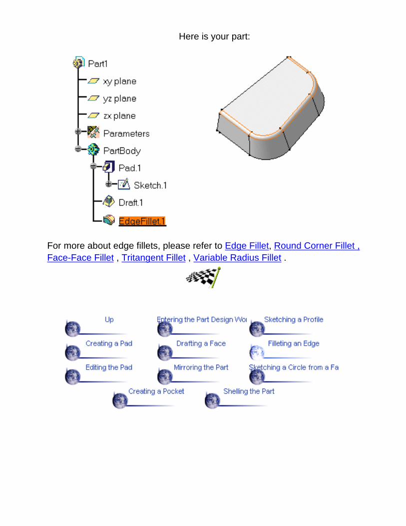
Here is your part:
For more about edge fillets, please refer to Edge Fillet, Round Corner Fillet ,Face-Face Fillet , Tritangent Fillet , Variable Radius Fillet .

Editing the PadActually, you would like the pad to be thicker. This task shows you how to editthe pad, then how to color the part.
1. Double-click the pad.
You can do it in the specification tree if you wish.
2. In the Pad Definition dialog box that appears, enter 90 mm as the newlength value.
3. Click OK.
The part is modified.
4. Now select the Edit -> Properties command and click the Graphic tab tochange the color of your part.
5. Click the color of your choice and click OK.
To have details about how to change graphic properties, please refer to CATIA- Infrastructure User's Guide Version 5. The part now looks like this:


Mirroring the PartNow, you are going to duplicate the part using symmetry. This task will show youhow easy it is.
1. Click the Mirror icon .
The Mirror Definition dialog box isdisplayed.2. Select the reference face you needto duplicate the part.
The name of this face appears in theMirroring element field. 3. Click OK.
The part is mirrored and the specification tree indicates this operation.
The next task proposes you to use the new large face you have just created ontop of the part.For more about mirror, please refer to Mirror.


Sketching a Circle from a FaceIn this task, you will learn how to:
open a sketch on an existing facecreate a circle in order to create a pocket
1. Select this face to define the workingplane.
2. Click the Sketcher icon to enter theSketcher workbench.
3. Once in the Sketcher workbench, click
this Circle icon to create a basic circle.
4. Click the circle center in the middle of theface and drag the cursor to sketch the circle.
5. Click once you are satisfied with the sizeof the circle.
6. Then, click the exit Sketcher icon to return to the 3D world.This is your part:

For more about Sketcher elements, please refer to Sketching Profiles.

Creating a PocketIn this task, you will learn a method to create a pocket using the profile you havejust created.
1. Select the circle you have just sketched, if it isnot already selected.
2. Click the Pocket icon .
The Pocket Definition dialog box is displayed andCATIA previews a pocket with default parameters.
3. Set the Up to last option to define the limit ofyour pocket.
This means that the application will limit the pocketonto the last possible face, that is the pad bottom.4. Click OK.
This is your pocket:

For more about pockets, please refer to Pocket, and Pocket not Normal toSketch Plane.

Shelling the PartTo end the scenario, you will learn how to shell the part.
1. Select the bottom face of the part.
2. Click the Shell icon .
The Shell Definition dialog box isdisplayed.
3. Select the face to be removed.
4. Click OK to shell the part using the default inner thickness value.
You have defined a positive value, which means that the application isgoing to enter a thin part thickness.

For more about shells, please refer to Shell.
This completes the Part Design tutorial. Now, let's take a closer look at theapplication.

Basic User TasksThe basic tasks you will perform in the Part Design workbench are mainly the creationof features and surfaces you will use to create your part. To create features you willsometimes sketch profiles first or use existing features.
This section will explain and illustrate how to create various kinds of features andsurfaces. The table below lists the information you will find.

Opening a New CATPart DocumentThis task shows you how to open a new CATPart document.
1. Select the File -> New commands (or click the New icon).
The New dialog box is displayed, allowing you to choose the type of document you need.
2. Select Part in the List of Types field and click OK.
The Part Design workbench is loaded and a CATPart document opens.
The Part Design workbench document is divided into:two windows: the specification tree and the geometry areaspecific toolbars : refer to Part Design Workbencha number of contextual commands available in the specification tree and in the geometry. Remember that thesecommands can also be accessed from the menu bar.

You will notice that CATIA provides three planes to let you start your design. Actually, designing a part from scratch willfirst require designing a sketch. Sketching profiles is performed in the Sketcher workbench which is fully integrated into
Part Design. To open it, just click the Sketcher icon and select the work plane of your choice.
The Sketcher workbench then provides a large number of tools allowing you to sketch the profiles you need. For moreinformation, refer to Sketcher documentation.
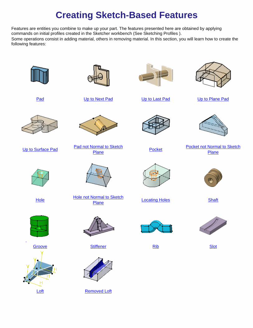
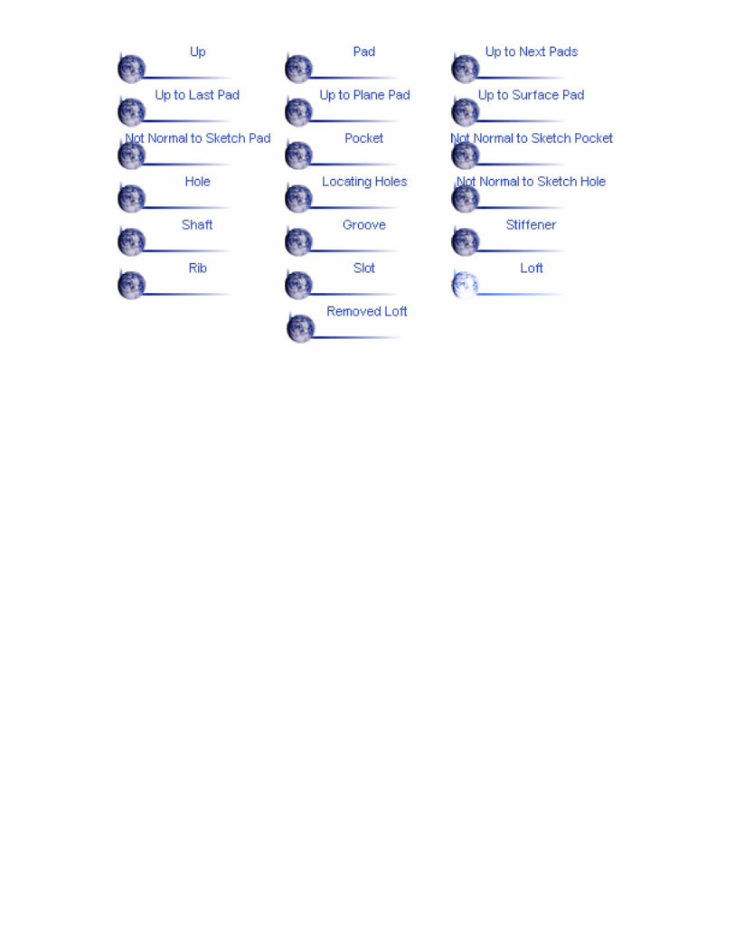
Creating Sketch-Based FeaturesFeatures are entities you combine to make up your part. The features presented here are obtained by applyingcommands on initial profiles created in the Sketcher workbench (See Sketching Profiles ).Some operations consist in adding material, others in removing material. In this section, you will learn how to create thefollowing features:
Pad Up to Next Pad Up to Last Pad Up to Plane Pad
Up to Surface Pad Pad not Normal to SketchPlane Pocket Pocket not Normal to Sketch
Plane
Hole Hole not Normal to SketchPlane Locating Holes Shaft
Groove Stiffener Rib Slot
Loft Removed Loft


PadCreating a pad means extruding a profile in one or two directions. CATIA lets you choose the limits of creation as well asthe direction of extrusion.
Basic PadsThis task shows you how to create a basic pad using a closed profile, the Dimension and Mirrored extent options.
Open the Pad1.CATPart document from the \online\samples\part_design directory.
1. Select the profile to be extruded.
By default, CATIA will extrude normal to the plane used to create the profile. To see how to change the extrusiondirection, refer to Pad not Normal to Sketch Plane .
2. Click the Pad icon .
The Pad Definition dialog box appears and CATIA previews the pad to be created.
You will notice that by default, CATIA specifies the length of your pad. To see other creation options, see Up to NextPad, Up to Last Pad, Up to Plane Pad, Up to Surface Pad.

3. Enter 69 in the Length field or select LIM1 and drag it upwards to 69to increase the length value.
4. Click the Mirrored extent option to extrude the profile in theopposite direction too.
4. Click OK.
The pad is created. The specification tree indicates that it has beencreated.
A Few Notes About PadsCATIA allows you to create pads from open profiles provided existing geometry can trim the pads. The pad belowhas been created from an open profile which both endpoints were stretched onto the inner vertical faces of thehexagon. The option used for Limit 1 is "Up to next". The inner bottom face of the hexagon then stops theextrusion. Conversely, the Up to next option could not be used for Limit2.
Initial open profile Preview Result
Note that reversing the arrow of Limit 2 creates material in the opposite side:

Pads can also be created from sketches including several profiles. These profiles must not intersect.
In the following example, the sketch to be extruded is defined by a square and a circle. Applying the Padcommand on this sketch lets you obtain a cavity:

`Up to Next' PadsThis task shows you how to create a pad using the `Up to Next' option. Thiscreation mode lets the application detect the existing material to be used forlimiting the pad length.Open the Pad2.CATPart document from the \online\samples\part_designdirectory.
1. Select the profile to beextruded, that is thecircle.
2. Click the Pad icon .
The Pad Definition dialogbox appears and CATIApreviews a pad with adefault dimension value.3. Click the arrow in thegeometry area to reversethe extrusion direction (orclick the Reverse Directionbutton).
4. In the Type field, setthe Type option to `Up tonext'.

This option assumes anexisting face canbe used to limit thepad. CATIApreviews the pad tobe created. Thealready existingbody is going tolimit the extrusion.5. Click OK.
The pad is created. Thespecification treeindicates this creation.
By default, the application extrudes normal to the plane used to create the profile.To learn how to change the direction, refer toPad not Normal to Sketch Plane .

'Up to Last' Pads
This task shows how to create pads using the `Up to last' option.
Open the Pad3.CATPart document from the \online\samples\part_designdirectory.
1. Select the profile to be extruded, that is the circle.
2. Click the Pad icon .
The Pad Definition dialog box appears and CATIA previews a pad with 10mm as the default dimension value.3. Click the arrow in the geometry area to reverse the extrusion direction(or click the Reverse Direction button).
4. In the Type field, set the Type option to `Up to last'.
CATIA previews the pad to be created.The last face encountered by theextrusion is going to limit the pad.

5. Click OK.
The pad is created. The specification tree indicates this creation.
By default, CATIA extrudes normal to the plane used to create the profile. To seehow to change the direction, refer to Pad not Normal to Sketch Plane .


'Up to Plane' PadsThis task shows how to create pads using the Up to plane option.
Open the Pad4.CATPart document from the \online\samples\part_designdirectory.
1. Select the profile to be extruded.
2. Click the Pad icon .
The Pad Definition dialog box appearsand CATIA previews a pad with 10mm as the default dimension value.3. Click the arrow in the geometryarea to reverse the extrusion direction(or click Reverse Direction).
4. In the Type field, set the Typeoption to `Up to plane'.
5. Select Plane.4.

CATIA previews the pad to becreated. The plane is going tolimit the extrusion.
6. Click OK.
The pad is created. The specificationtree indicates this creation.
By default, CATIA extrudes normal to the plane used to create the profile. To seehow to change the direction, refer to Pad not Normal to Sketch Plane .

`Up to Surface' Pads
This task shows how to create pads using the Up to Surface option.
Open the Pad5.CATPart document from the \online\samples\part_designdirectory.
1. Select the profile to be extruded.
2. Click the Pad icon .
The Pad Definition dialog box appearsand CATIA previews a pad with adefault dimension value.
3. In the Type field, set the Typeoption to Up to surface.
4. Select the face as shown.
CATIA previews the pad to becreated. The plane is going to limit theextrusion.

5. Click OK.
The pad is created. The specificationtree indicates this creation.
By default, the application extrudes normal to the plane used to create the profile.To see how to change the direction, refer to Pad not Normal to Sketch Plane .

Pad not Normal to Sketch PlaneThis task shows how to create a pad using a direction that is not normal to theplane used to create the profile.
Open the Pad6.CATPart document from the \online\samples\part_designdirectory.
1. Select the profile youwish to extrude.
2. Click the Pad icon .
The Pad Definition dialog box appears and CATIA previews the padto be created.
3. Set the Up to plane option and select plane yz. For more about thistype of creation, refer to Up to Plane Pads.
4. Click the More button to display the whole dialog box.
5. Uncheck the Normal to sketch option and select the linee as shownto use it as a reference.

CATIA previews thepad with the newcreation direction.
6. Click OK to confirm the creation.
The pad is created. The specification tree indicates this creation.


PocketCreating a pocket consists in extruding a profile and removing the material resultingfrom the extrusion. CATIA lets you choose the limits of creation as well as the directionof extrusion. The limits you can use are the same as those available for creating pads.To know how to use them, seeUp to Next Pockets , Up to Last Pads , Up to PlanePads , Up to Surface Pads .
Basic PocketsThis task shows you how to create a pocket, that is a cavity, in an alreadyexisting part.
Open the Pocket1.CATPart document from the \online\samples\part_designdirectory.
1. Select the profile.
2. Click the Pocket icon .
The Pocket Definition dialog box is displayed and CATIA previews apocket.
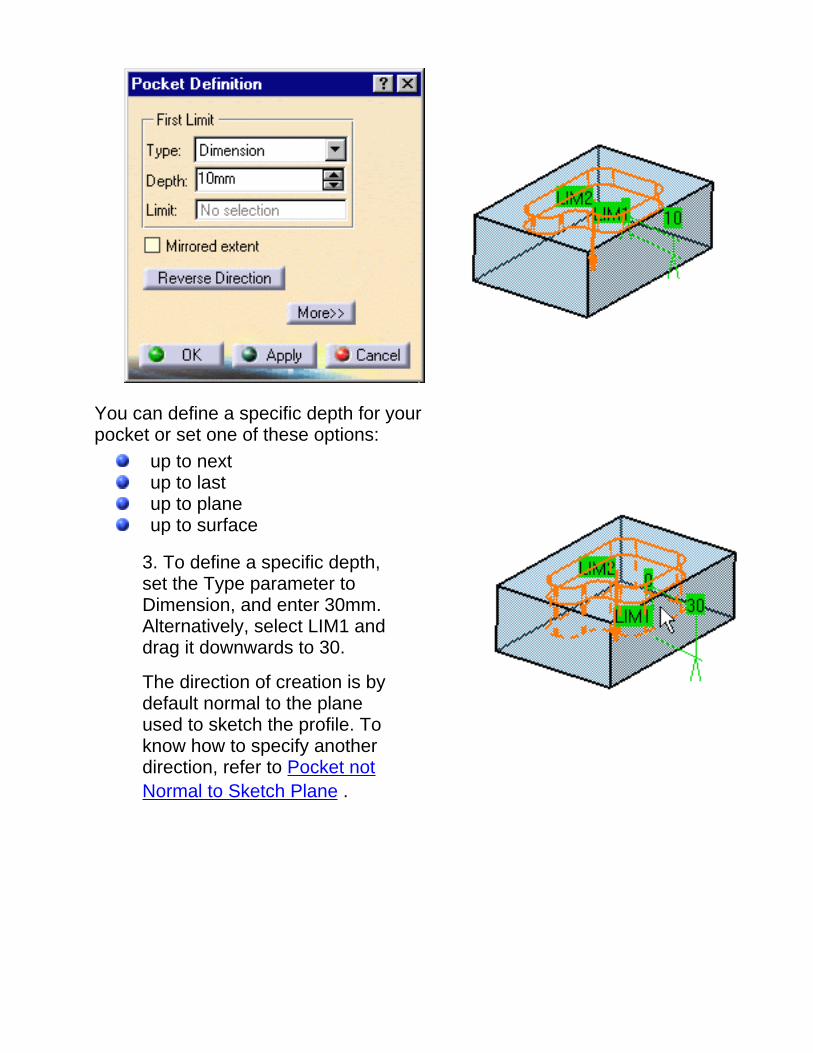
You can define a specific depth for yourpocket or set one of these options:
up to nextup to lastup to planeup to surface
3. To define a specific depth,set the Type parameter toDimension, and enter 30mm.Alternatively, select LIM1 anddrag it downwards to 30.
The direction of creation is bydefault normal to the planeused to sketch the profile. Toknow how to specify anotherdirection, refer to Pocket notNormal to Sketch Plane .

4. Click OK.
The specification tree indicatesthis creation. This is yourpocket:
A Few Notes About PocketsCATIA allows you to create pockets from open profiles provided existinggeometry can trim the pockets. The example below illustrates this concept.
If your pocket is the first feature of a new body, CATIA creates material:

Pockets can also be created from sketches including several profiles. Theseprofiles must not intersect.
In the following example, the initial sketch is made of eight profiles. Aplyingthe Pocket command on this sketch lets you create eight pockets:
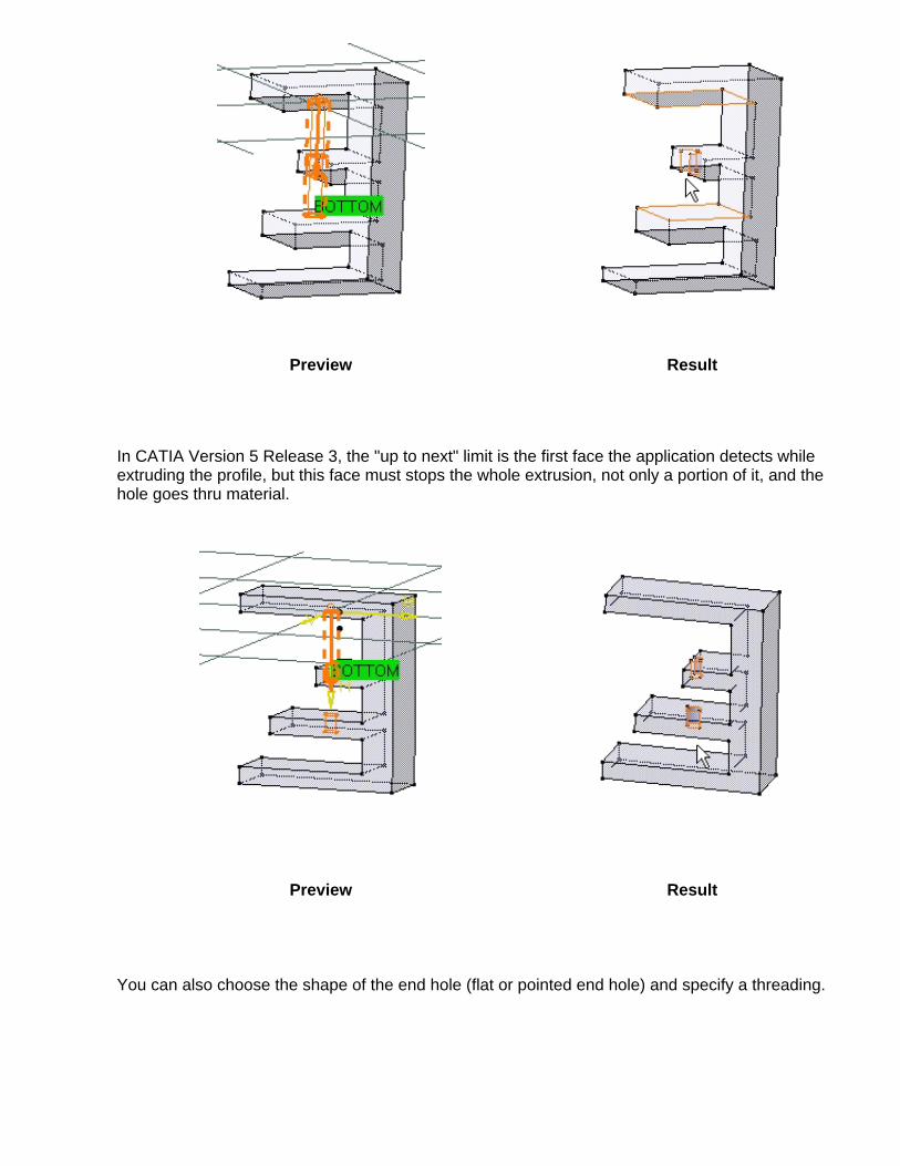
The "Up to next" creation mode behaves differently depending on the release ofthe product you are using. Using CATIA Version 5 Release 2, the "up to next"limit is the very first face the application detects while extruding the profile. Thisis an example of what you can get:

Preview Result
Using CATIA Version 5 Release 3, the "up to next" limit is the first face theapplication detects while extruding the profile. This face must stops thewhole extrusion, not only a portion of it, and the hole goes thru material, asshown in the figure below:
Preview Result


Pocket not Normal to Sketch PlaneThis task shows how to create a pocket using a direction that is not normal to the plane used tocreate the profile.
Open the Pocket2.CATPart document from the \online\samples\part_design directory.
1. Select the profile.
2. Click the Pocket icon .
The Pocket Definition dialog box appears and CATIApreviews a pocket normal to the sketch plane:
3. Set the First Limit typeto Up to next.
4. Click the More button to display the whole dialog box.
5. Uncheck the Normal to sketch option.6. Select the bottom edge as indicated to define a new creation direction.

7. Click OK to create the pocket.
The specification tree indicates it has beencreated.

HoleCreating a hole consists in removing material from a body. Various shapes of standard holes can becreated. These holes are:
Simple Tapered Counterbored Countersunk Counterdrilled
If you choose to create a...
Counterbored hole: the counterbore diameter must be greater than the hole diameter and thehole depth must be greater than the counterbore depth.
Countersunk hole: the countersink diameter must be greater than the hole diameter and thecountersink angle must be greater than 0 and less than 180 degrees.
Counterdrilled hole: the counterdrill diameter must be greater than the hole diameter, the holedepth must be greater than the counter drill depth and the counterdrill angle must be greater than 0and less than 180 degrees.
Whatever hole you choose, you need to specify the limit you want. There is a variety of limits:
Blind Up to Next Up to Last Up to Plane Up to Surface
The "Up to next" creation mode behaves differently depending on the release of the product you areusing. In CATIA Version 5 Release 2, the "up to next" limit is the very first face the applicationdetects while extruding the profile.
Preview Result
In CATIA Version 5 Release 3, the "up to next" limit is the first face the application detects whileextruding the profile, but this face must stops the whole extrusion, not only a portion of it, and thehole goes thru material.
Preview Result
You can also choose the shape of the end hole (flat or pointed end hole) and specify a threading.

Creating a HoleThis task illustrates how to create a counterbored hole while constraining its location.
Open the Hole1.CATPart document from the \online\samples\part_design directory.
1. Click the Hole icon .
2. Select the circular edge and upper face as shown.
CATIA can now define one distance constraint toposition the hole to be created. The hole will beconcentric to the circular edge.
For more about locating holes, please refer to Locating a Hole .
The Hole Definition dialog box appears and CATIApreviews the hole to be created. The Sketcher grid isdisplayed to help you create the hole. By default,CATIA previews a simple hole whose diameter is10mm and depth 10mm. Contextual creation commands are available on theBOTTOM text.
4. Now, define the hole you wish to create. Enter 24mm as the diameter value and 25mm as thedepth value.
6. Set the Bottom option to V-Bottom to create a pointed hole and enter 110 in the Angle field.

You could also define a creation direction normal to the surface of your choice and a threading.
7. Now, click the Type tab to access the type of hole you wish to create. You are going to create acounterbored hole.
You will notice that the glyph assists you in defining the desired hole.

8. Enter 30mm in the Diameter field and 8mm as the depth value .
The preview lets you see the new diameter.
14. Click OK.
The hole is created. The specification tree indicatesthis creation.
You will notice that the sketch used to create the holealso appears under the hole's name. This sketchconsists of the point at the center of the hole.

Locating a HoleThis task shows how to constrain the location of the hole to be created withoutusing the Sketcher workbench `s tools.
1. Multiselect two edges and the face on which you wish to position thehole.
2. Click the Hole icon and specify the required data in the dialog box tocreate the desired hole (see Creating a Hole).
CATIA previews the constraints you are creating.
3. Click OK to create the hole.
CATIA positions the hole using default constraints.
4. To access the constraints, edit the hole and double-click the constraint ofinterest or double-click the sketch in the specification tree to enter theSketcher workbench.
You can edit the constraints if you wish to reposition the hole.

Remember That...
The area you click determines the location of the hole, but you can dragthe hole onto desired location during creation using the left mouse button.If the grid display option is activated, you can use its properties.
Selecting a circular face makes the hole concentric with this face.However, CATIA creates no concentricity constraint.
Multiselecting a circular edge and a face makes the hole concentric to thecircular edge. In this case, CATIA creates a concentricity constraint.

CATIA always limits the top of the hole using the Up to next option. Inother words, the next face encountered by the hole limits the hole.
In the following example, the hole encounters a fillet placed above theface initially selected. The application redefines the hole's top onto thefillet.
Remember that the Sketcher workbench provides commands to constraintthe point used for locating the hole. See Setting Constraints.
Selecting an edge and a face allows the application to create one distanceconstraint. While creating the hole, you can double-click this constraint toedit its value.

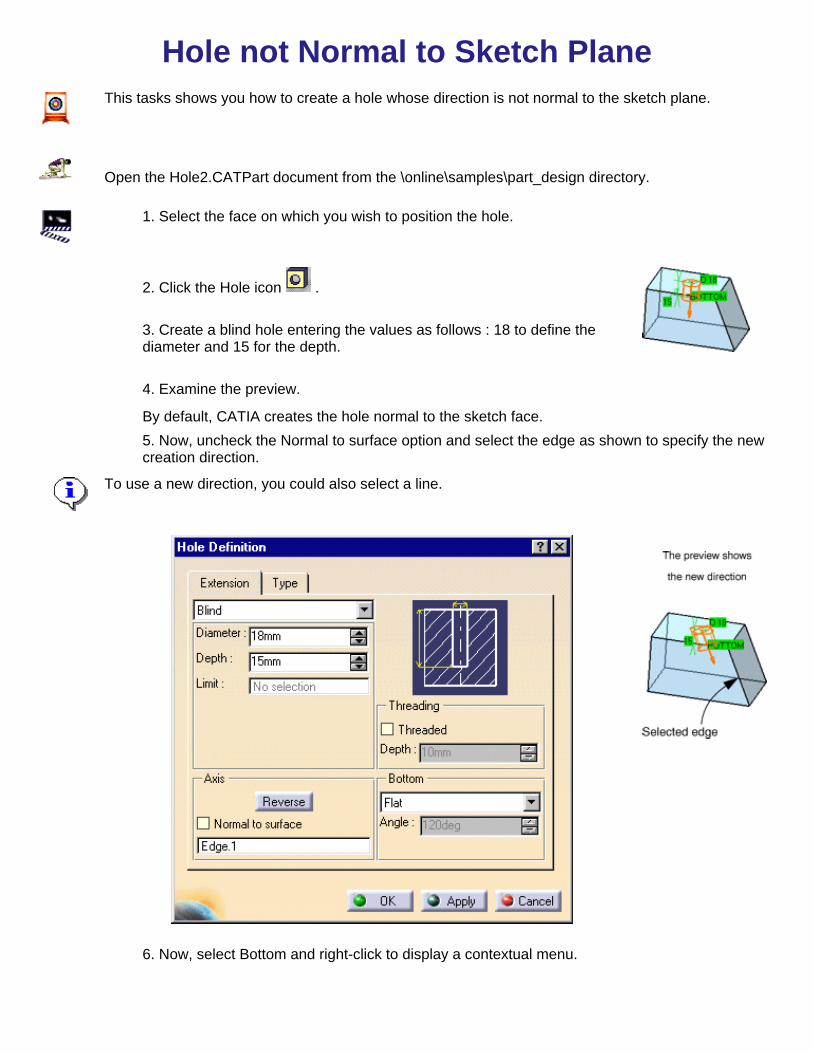
Hole not Normal to Sketch PlaneThis tasks shows you how to create a hole whose direction is not normal to the sketch plane.
Open the Hole2.CATPart document from the \online\samples\part_design directory.
1. Select the face on which you wish to position the hole.
2. Click the Hole icon .
3. Create a blind hole entering the values as follows : 18 to define thediameter and 15 for the depth.
4. Examine the preview.
By default, CATIA creates the hole normal to the sketch face.5. Now, uncheck the Normal to surface option and select the edge as shown to specify the newcreation direction.
To use a new direction, you could also select a line.
6. Now, select Bottom and right-click to display a contextual menu.

7. Select V-Bottom from the menu. Note that this option is available in the dialog box too.
8. Enter 90deg in the Angle field to define the angle of the V shape.9. Click OK to confirm the creation.
The hole is created. The specification tree indicates it has been created.

Shaft
This task illustrates how to create a shaft, that is a revolved feature.
The sketch must include a profile and an axis about which the feature will revolve.
Open the Shaft.CATPart document from the \online\samples\part_design directory.
1. Select the closed profile.
2. Click the Shaft icon .
The Shaft Definition dialog box is displayed and CATIA previews a roundfeature. The First Angle value is by default 360 degrees.
3.CATIA previews the limitsLIM1 and LIM2 of the shaft tobe created. Select LIM1 anddrag it onto 250.

3. Now enter 40 degrees inthe Second angle field.
4. Click OK.
The shaft is created. Thespecification tree mentions ithas been created.
You can use open profiles for creating shafts. CATIA uses existing geometry to trimmaterial. In the example below, the red face trims the extremity to the left. The axisabout which the feature is created trims the opposite extremity.
Open profile Result

GrooveGrooves are revolved features that retrieves material from existing features. This taskshows you how to create a groove, that is how to revolve a profile about an axis (orconstruction line).Open the Groove.CATPart document from the \online\samples\part_design directory.
1. Click the Groove icon .
2. Select the sketch.
The profile and the axis mustbelong to the same sketch.
The Groove Definition dialog box is displayed and CATIA previews agroove entirely revolving about the axis.
3.CATIA previews the limits LIM1 and LIM2 of the groove to be created.You can select these limits and drag them onto the desired value or enterangle values in the appropriate fields. For our scenario, select LIM1 anddrag it onto 100, then enter 60 in the Second angle field.

4. Examine thepreview. Just a portionof material is going tobe removed now.
5. Click OK to confirm theoperation.
CATIA removes materialaround the cylinder. Thespecification tree indicatesthe groove has been created.
This is your groove:


StiffenerThis task shows you how to create a stiffener by specifying creation directions.
Open the Stiffener.CATPart document from the \online\samples\part_designdirectory.
1. Select the profile to beextruded.
This open profile has beencreated in a plane normalto the face on which thestiffener will lie.
If you need to use an open profile, make sure that existing material can fully limitthe extrusion of this profile
2. Click the Stiffener icon .
The Stiffener Definition dialog box is displayed, providing a defaultthickness value.

CATIA previews a stiffener which thickness is equal to 10mm.
The extrusion will be made in three directions, two of which areopposite directions. Arrows point in these directions.
3. Uncheck the Symmetrical extent option.
The extrusion will be made in two directions only.
To obtain the directions you need, you can also click the arrows. Notethat you can access contextual commands on these arrows. Thesecommands are the same as those available in the dialog box.
4. Check theSymmetrical extentoption again.
5.Just to examine the Depth option, click the Reverse direction optionin the dialog box, or click the arrow in the geometry area.
The result differs very much from the previous stiffener. Just a smallportion of material will be created:

6. As you prefer to create material forming a transition between the basis ofthe part and the triangle, reverse the direction again, and click OK.
The stiffener is created. The specification tree indicates it has beencreated.


RibThis task shows you how to create a rib, that is a profile you sweep along a center curve to creatematerial.
Open the Rib.CATPart document from the \online\samples\part_design directory.
1. Click the Rib Icon .
The Rib Definition dialog box is displayed.
2. Select the profile you wish to sweep. Your profile has been designed in a plane normal to the planeused to define the center curve. It is a closed profile.
You can use an open profile provided existing material can limit the rib.
You can control its position by choosing one of the following options:Keep angle: keeps the angle value between the sketch plane used for the profile and thetangent of the center curve.Pulling direction: sweeps the profile with respect to a specified direction (see pulling directionbelow).Reference surface
3. To go on with our scenario, let's maintain the Keep angle option. Select the center curve.
The center curve is open. To create a rib you can use open profiles and closed center curves too.Center curves can be discontinuous in tangency.
The application now previews the rib to be created.

The Merge ends option is to be used in specific cases. It create materials between the ends of the riband existing material.
4. Click OK.
The rib is created. The specification tree mentions thiscreation.
Using the edge as shown as the pulling direction, you wouldobtain this:
A Few Words about the Keep Angle OptionThe position of the profile in relation to the center curve determines the shape of the resulting rib. Whensweeping the profile, the application keeps the initial position of the profile in relation to the nearest point ofthe center curve. The application computes the rib from the position of the profile.In the example below, the application computes the intersection point between the plane of the profile andthe center curve, then sweeps the profile from this position.


SlotThis task shows you how to create a slot, that is a profile you sweep along acenter curve to remove material .
Open the Slot.CATPart document from the \online\samples\part_designdirectory.
1. Click the Slot icon .
The Slot Definition dialog box is displayed.
2. Select the profile.
The profile has been designed in a planenormal to the plane used to define thecenter curve. It is closed.
You can control its position by choosingone of the following options:
Keep angle: keeps the angle valuebetween the sketch plane used forthe profile and the tangent of thecenter curve.Pulling direction: sweeps the profilewith respect to a specified direction.Reference surface
3. To go on with our scenario, let's maintainthe Keep angle option. To know more thisoption, please refer to A Few Notes aboutthe Keep Angle Option.
Now, select the center curve along whichCATIA will sweep the profile.
The center curve is open. To create a ribyou can use open profiles and closedcenter curves too. Center curves can bediscontinuous in tangency.
The application previews the slot.

The Merge ends option is to be used in specific cases. It lets the applicationcreate material between the ends of the slot and existing material.
4. Click OK.
The slot is created. The specification treeindicates this creation.

LoftThis task shows how to create a loft feature.
You can generate a loft feature by sweeping one or more planar section curvesalong a computed or user-defined spine. The feature can be made to respect oneor more guide curves. The resulting feature is a closed volume.Open the Loft.CATPart document from the samples/part_design directory.
1. Click the Loft icon .
The Loft Definition dialog box appears.

2. Select the three sectioncurves as shown:
They arehighlighted inthe geometry area.
3. Select the four guide curves.
They are highlighted in the geometry area.
4. It is possible to edit the loft reference elements by first selecting acurve in the dialog box list then choosing a button to either:
Remove the selected curve Replace the selected curve by another curve.Add another curve.

By default, the application computes a spine, but if you wish to impose a curve asthe spine to be used, you just need to click the Spine tab then the Spine field andselect the spine of your choice in the geometry.
5. Click OK to createthe volume.
The feature(identified asLoft.xxx) is added tothe specification tree.

Remove Lofted MaterialThis task shows how to remove lofted material.
The Remove Loft capability generates lofted material surface by sweeping one ormore planar section curves along a computed or user-defined spine thenremoves this material. The material can be made to respect one or more guidecurves.Open the Remove_Loft.CATPart document from the samples/part_designdirectory.
1. Click the Remove Loft icon .
The Remove Loft Definition dialog box appears.

2. Select both section curves as shown Sketch.3 and Sketch.4):
They are highlighted in the geometry area.
3. Select the point as shown on section 2 to define the closing point.
4. Select the four guide curves.
They are highlighted in the geometry area.

5. It is possible to edit the loft reference elements by first selecting acurve in the dialog box list then choosing a button to either:
Remove the selected curve Replace the selected curve by another curve.Add another curve.
By default, the application computes a spine, but if you wish to impose a curve asthe spine to be used, you just need to click the Spine tab then the Spine field andselect the spine of your choice in the geometry.
6. Click OK to create the lofted surface.
The feature (identified as RemovedLoft.xxx) is added to thespecification tree.


Creating Dress-Up FeaturesDressing up features is done by applying commands to one or more supports. CATIA provides a largenumber of possibilities to achieve the features meeting your needs. The application lets you create thefollowing dress-up features:
Edge Fillet Round Corner Fillet Face-Face Fillet Tritangent Fillet Variable RadiusFillet
Chamfer Basic Draft Draft with partingelement Shell Thickness
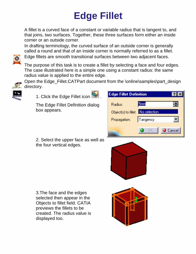
Edge FilletA fillet is a curved face of a constant or variable radius that is tangent to, andthat joins, two surfaces. Together, these three surfaces form either an insidecorner or an outside corner.In drafting terminology, the curved surface of an outside corner is generallycalled a round and that of an inside corner is normally referred to as a fillet.Edge fillets are smooth transitional surfaces between two adjacent faces.
The purpose of this task is to create a fillet by selecting a face and four edges.The case illustrated here is a simple one using a constant radius: the sameradius value is applied to the entire edge.Open the Edge_Fillet.CATPart document from the \online\samples\part_designdirectory.
1. Click the Edge Fillet icon .
The Edge Fillet Definition dialogbox appears.
2. Select the upper face as well asthe four vertical edges.
3.The face and the edgesselected then appear in theObjects to fillet field. CATIApreviews the fillets to becreated. The radius value isdisplayed too.

3. Click OK to confirm theoperation.
The edges are filleted. Thecreation of this fillet is indicated inthe specification tree.

Round Corner FilletRound corner fillets are fillets whose ends have been rounded off. This taskshows how to create this type of fillet.Open the Round_Fillet.CATPart document from the \online\samples\part_designdirectory.
1. Select the edge to be filleted.
2. Click the Edge Fillet icon .
The Edge Fillet Definition dialogbox appears.3. Enter a radius value. Forexample, enter 9mm.
CATIA previews the fillet.
4. Click OK.
The specification tree indicates thiscreation. This a round corner fillet:
You will notice that an edge hasbeen modified.


Face-Face FilletYou generally use the Face-face fillet command when there is no intersectionbetween the faces or when there are more than two sharp edges between thefaces.This task shows how to create a face-face fillet.
Open the Face_Fillet.CATPart document from the \online\samples\part_designdirectory.
1. Click the Face-Face Fillet
icon .
The Face-Face FilletDefinition dialog box appears.
2. Select the faces to befilleted.
The application previews thefillet to be created:
3. Enter a radius value in theRadius field if you are notsatisfied with the defaultone.For example, enter31mm.

4. Click OK.
The faces are filleted.This filletis indicated in the specificationtree.

Variable Radius FilletVariable radius fillets are curved surfaces defined according to a variable radius.A variable radius corner means that at least two different constant radii areapplied to two entire edges.
This task shows how to create a variable radius fillet.
Open the Variable_Fillet.CATPart document from the\online\samples\part_design directory.
1. Click the Variable Radius Fillet icon .
The Variable Radius Fillet Definition dialog box appears.
2. Select the edge to be filleted.
CATIA detects the two vertices and displays two radius values.
3. Enter a new radius value tochange the radius of thevertex on the left.
The new radius value isdisplayed.
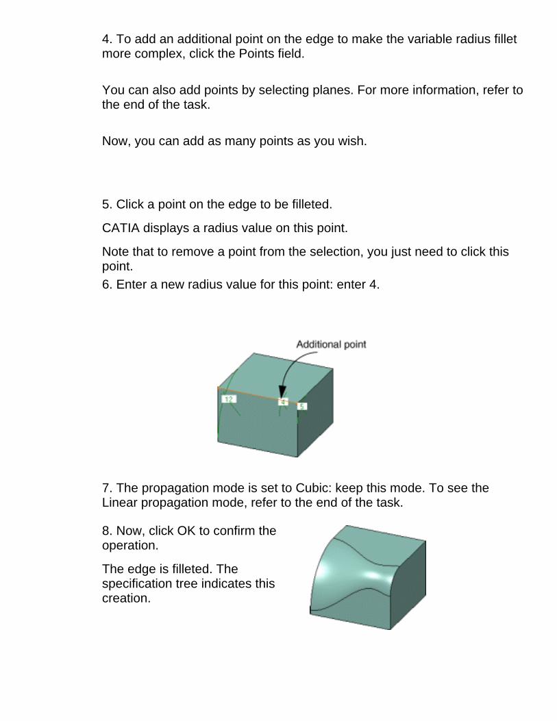
4. To add an additional point on the edge to make the variable radius filletmore complex, click the Points field. You can also add points by selecting planes. For more information, refer tothe end of the task.
Now, you can add as many points as you wish.
5. Click a point on the edge to be filleted.
CATIA displays a radius value on this point.
Note that to remove a point from the selection, you just need to click thispoint.6. Enter a new radius value for this point: enter 4.
7. The propagation mode is set to Cubic: keep this mode. To see theLinear propagation mode, refer to the end of the task.
8. Now, click OK to confirm theoperation.
The edge is filleted. Thespecification tree indicates thiscreation.

More About Variable Radius FilletsThis is the fillet you would obtainusing the Linear propagation mode.Examine the difference!
To add additional points on the edge to be filleted, you can selectplanes. CATIA computes the intersections between these planes andthe edge to determine the useful points.
In this example, three planes were selected.
Now, if you move these planes later, CATIA will compute theintersections again and modify the fillet accordingly.
Points can be added too by selecting 3D points.
You can use the radius value R=0 to create a variable radius fillet.


Tritangent FilletThe creation of tritangent fillets involves the removal of one of the three facesselected.
This task shows hows to create a tritangent fillet.You need three faces two of which are supporting faces.
Open the Tritangent_fillet.CATPart document from the\online\samples\part_design directory.
1. Click the Tritangent Fillet icon .
The Tritangent Fillet Definition dialog box appears.
2. Select the faces to be filleted.
3. Select the face to beremoved, that is the upperface.
The fillet will be tangent tothis face.This face appears in darkred.

4. Click OK.
The faces are filleted. Thecreation of this fillet isindicated in thespecification tree.
Multiselecting three faces then clicking the Tritangent Fillet icon tells theapplication to remove the third face.
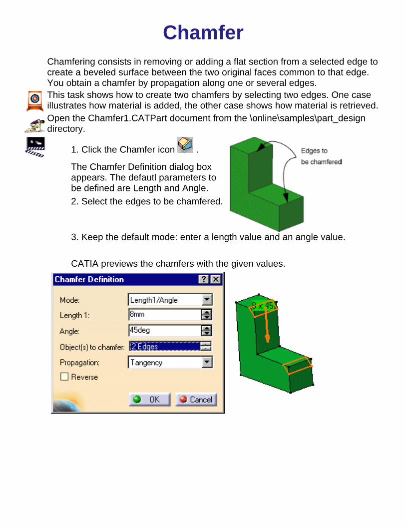
ChamferChamfering consists in removing or adding a flat section from a selected edge tocreate a beveled surface between the two original faces common to that edge.You obtain a chamfer by propagation along one or several edges.This task shows how to create two chamfers by selecting two edges. One caseillustrates how material is added, the other case shows how material is retrieved.Open the Chamfer1.CATPart document from the \online\samples\part_designdirectory.
1. Click the Chamfer icon .
The Chamfer Definition dialog boxappears. The defautl parameters tobe defined are Length and Angle.2. Select the edges to be chamfered.
3. Keep the default mode: enter a length value and an angle value.
CATIA previews the chamfers with the given values.

4. Click OK.
The specification tree indicates thiscreation.These are your chamfers:
Chamfers can be created by selecting a face whose edges are to be chamfered.

Basic DraftDrafts are defined on molded parts to make them easier to remove frommolds.The characteristic elements are:
pulling direction: this direction corresponds to the reference fromwhich the draft faces are defined.draft angle: this is the angle that the draft faces make with the pullingdirection. This angle may be defined for each face.parting element: this plane, face or surface cuts the part in two andeach portion is drafted according to its previously defined direction.For an example, please refer to Draft with Parting Element.neutral element: this element defines a neutral curve on which thedrafted face will lie. This element will remain the same during thedraft. The neutral element and parting element may be the sameelement.
There are two ways of determining the objects to draft. Either by explicitelyselecting the object or by selecting the neutral element, which makes CATIAdetect the appropriate faces to use.
This task shows you how to create a basic draft by selecting the neutralelement.Open the Draft2.CATPart document from the \online\samples\part_designdirectory.
1. Click the Draft icon .

The Draft Definition dialogbox is displayed and anarrow appears on the part,indicating the default pullingdirection.
2. Check the Selection by neutral face option to determine the selectionmode.
3. Select the upper face as the neutral element. This selection allows CATIAto detect the face to be drafted.
The neutral element is now displayed in blue, the neutral curve is in pink.The faces to be drafted are in dark red. You can also note that the pullingdirection is now displayed on top of the part. It is normal to the neutral face.
Note that when using the other selection mode (explicit selection), theselected objects are displayed in dark pink.

4. The default angle value is 5. Enter 7 degrees as the new angle value.
CATIA displays the new angle value in the geometry.
You can create drafts using a negative value.
7. Click OK to confirm the operation.
The faces are drafted. You can notice that material has been added.
A Few Notes about Drafts If you edit the sketch used fordefining the initial pad, CATIAintegrates this modification andcomputes the draft again. In thefollowing example, a chamfer wasadded to the profile.

If you need to draft several faces using a pulling direction normal to the neutralelement, keep in mind the following operating mode that will facilitate yourdesign:
Click and first select the neutral element of your choice. The pullingdirection that appears is then normal to the neutral element. Select the face tobe drafted and click OK to create your first draft.
Now, to create the other drafts in the same CATPart document, note that bydefault the application uses the same pulling direction as the one specified forcreating your first draft. As designers usually use a unique pulling direction,you do not need to redefine your pulling direction.

Draft with Parting ElementThis task shows how to create two basic drafts using parting elements.
Open the Draft1.CATPart document from the \online\samples\part_designdirectory.
1. Select the face to be drafted.
2. Click the Draft icon .
The Draft Definition dialog box appears andan arrow appears on the part, indicating thedefault pulling direction.
3. Click the Selection field and select planexy to define the neutral element.
The application displays the neutral curve inpink.4. Enter 13 degrees as the new angle value.
You can create drafts using a negative value.5. Now click the More button to display the whole dialog box andaccess the Parting Element option. Check the Draft with partingelement option if not already done.
6. Select plane xy, that is the sketch plane, as the partingelement. The initial part is a pad created using the Mirroredextent option. For more about this option, refer to Basic Pads .

7. Click OK.
The face is drafted. You can notice thatmaterial has been removed.

ShellShelling a feature means emptying it, while keeping a given thickness on itssides. Shelling may also consist in adding thickness to the outside. This taskshows both operations.
Open the Shell.CATPart document from the \online\samples\part_designdirectory.
1. Click the Shell icon . TheShell Definition dialog box appears.
2. Select the faces to remove.
3. Enter 1mm in the insidethickness field.
4. Click OK.
The feature is shelled: the selectedfaces are left open. This creationappears in the specification tree.
5. Now, double-click Shell.1 in the specification tree to edit it.

6. Enter 3mm in the outsidethickness field.7. Click OK.
Thickness has been added to theoutside.

ThicknessSometimes, some thickness has to be added or removed before machining thepart. The thickness command lets you do so.
This task shows you how to add thickness to a part.
Open the Thickness.CATPart document from the \online\samples\part_designdirectory.
1. Click the Thickness icon .
The Thickness Definition dialog boxis displayed.2. Select the faces to thicken.CATIA displays the thickness valuein the geometry.
3. Enter a positive value. Forexample, enter 20 mm.
4. Click OK.
The part is thickenedaccordingly. This creationappears in the specificationtree.


Creating Surface-Based Features
The features presented here are obtained by applying commands on surfaces or byusing surfaces for modifying features of any types.
Split Thick Surface
Close Surface Sew Surface

SplitYou can split a body with a plane, face or surface. The purpose of this task is toshow how to split a body by means of a surface.
Open the Split.CATPart document from the \online\samples\part_designdirectory.
1. Select the blue pad as the body to besplit.
2. Click the Split icon .
3. Select the splitting surface.
The Split Definition dialog box isdisplayed, indicating the splititng element.
An arrow appears indicating the portion ofbody that will be kept. If the arrow pointsin the wrong direction, you can click it toreverse the direction.

5. Click OK.
The body is split. Material has beenremoved.
The specification tree indicates youperformed the operation.

Close SurfaceThis task shows you to close surfaces.
Open the Close.CATPart document from the \online\samples\part_designdirectory.
1. Select the surface to be closed.
2. Click the Close Surface icon
.
The Close Surface Definitiondialog box is displayed.
5. Click OK.
The surface is closed . Thespecification tree indicates youperformed the operation.

Sew SurfaceSewing means joining together a surface and a body. This capability consists incomputing the intersection between a given surface and a body while removinguseless material. You can sew all types of surfaces onto bodies. This task showsyou how to do it.Open the Sew.CATPart document from the \online\samples\part_designdirectory.
1. Select the surface you wish to sew onto the body, that is the orangesurface.
2. Click the Sew Surface icon .
The Sew Surface Definition dialog boxis displayed, indicating the object to besewn.
3.An arrow appears indicating the portion of material that will be kept. Clickthe arrow to reverse the direction. The arrow must point in the direction asshown:
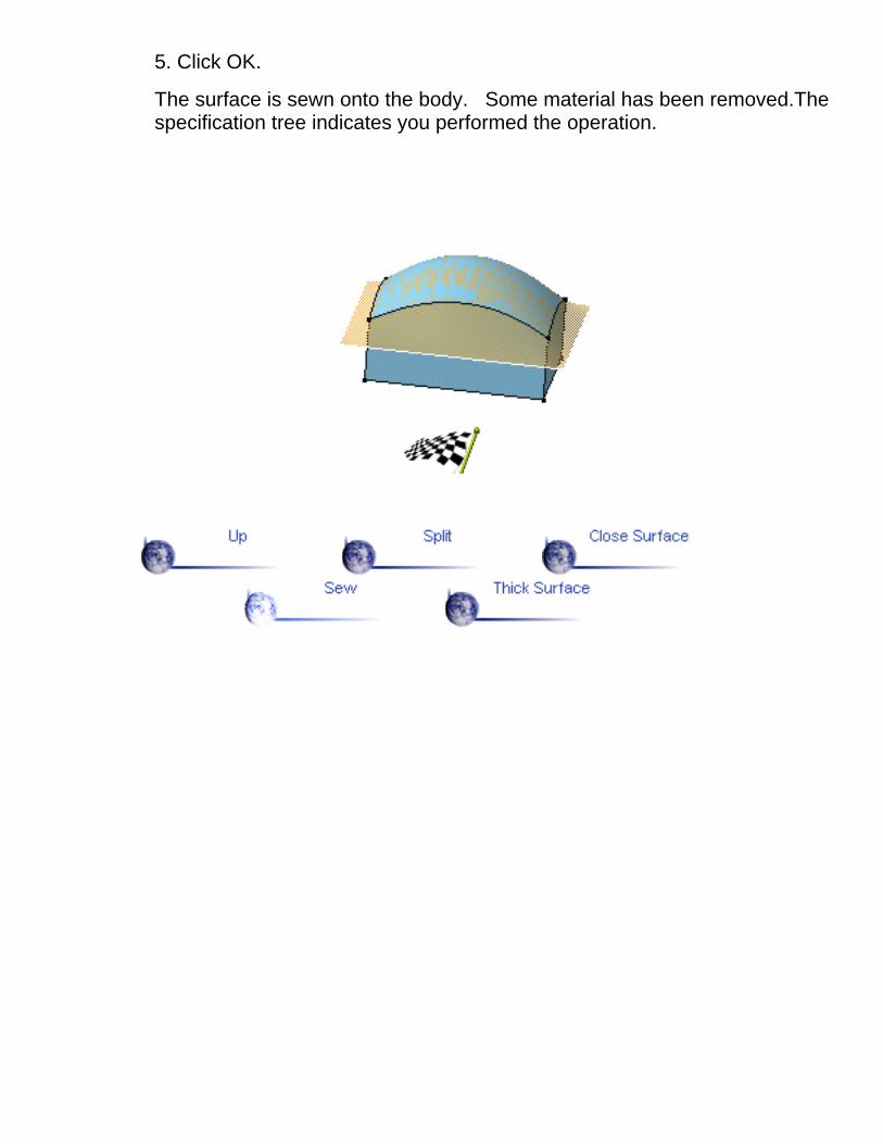
5. Click OK.
The surface is sewn onto the body. Some material has been removed.Thespecification tree indicates you performed the operation.

Thick SurfaceYou can add material to a surface in two opposite directions by using the ThickSurface capability. This task shows you how to do so.
Open the ThickSurface.CATPart document from the \online\samples\part_designdirectory.
1. Select the object you wish tothicken, that is the extrude element.
2. Click the Thick Surface icon
.
The Thick Surface Definitiondialog box is displayed.
In the geometry area, the arrowthat appears on the extrudeelement indicates the first offsetdirection.
3. Enter 25mm as the first offsetvalue and 12mm as the secondoffset value .
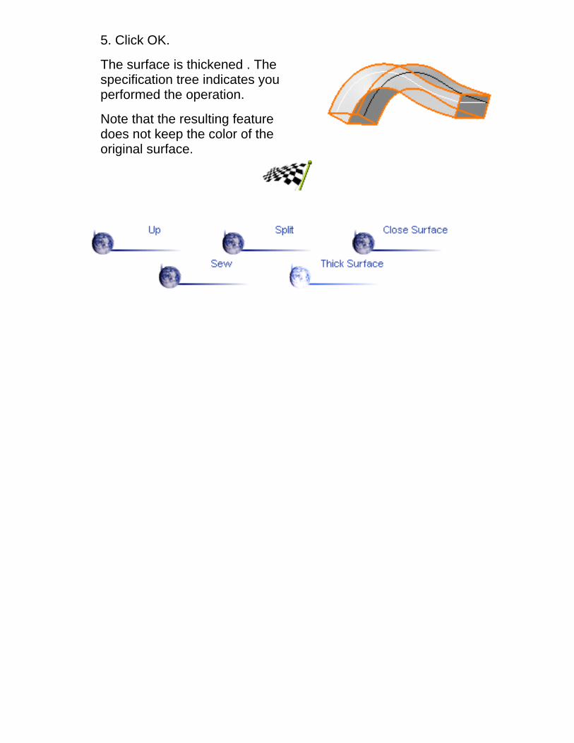
5. Click OK.
The surface is thickened . Thespecification tree indicates youperformed the operation.
Note that the resulting featuredoes not keep the color of theoriginal surface.

Creating Transformation FeaturesTransformation features are obtained by applying commands on existing features. Thissection illustrates the creation of the following features:
Translation Rotation Symmetry Mirror
Rectangular Pattern Circular Pattern User Pattern Scaling

TranslationThe Translate command applies to current bodies.
This task shows you how to translate a body.
1. Click the Translate icon .
The Translate Definition dialog box appears
2. Select a line to take its orientation as the translation direction or aplane to take its normal as the translation direction. For example,select zx plane.
You can also specify the direction by means of X, Y, Z vectorcomponents by using the contextual menu on the Direction area.3. Specify the translation distance by entering a value or using the Dragmanipulator. For example, enter 100mm.
4. Click OK to create thetranslated element.
The element (identified asTranslat.xxx) is added to thespecification tree


RotationThis task shows you how to rotate geometry about an axis. The command applies to currentbodies.
Open the Rotate.CATPart document from the \online\samples\part_design directory.
1. Click the Rotate icon .
The Rotate Definition dialog box appears.
2. Select a line as the rotation axis.3. Enter a value for therotation angle.
The element is rotated. Youcan drag it by using thegraphic manipulator to adjustthe rotation.
4. Click OK to create the rotated element.
The element (identified as Rotate.xxx) is added to the specification tree.

SymmetryThis task shows how to transform geometry by means of a symmetry operation.The Symmetry command applies to current bodies.
Open the Symmetry.CATPart document from the \online\samples\part_designdirectory.
1. Click the Symmetry icon .
The Symmetry Definition dialog box appears.
2. Select a point, line or plane as reference element. For our scenario,select plane zx.
3. Click OK to create thesymmetrical element.
The original element is nolonger visible but remains inthe specification tree.
The new element (identified asSymmetry.xxx) is added to thespecification tree.


PatternYou may need to create several identical features from an existing one and tosimultaneously position them on an part. Patterns let you do so.CATIA allows you to define three types of patterns: rectangular , circular anduser patterns. These features make the creation process easier.
Rectangular PatternThis task shows you how to duplicate the original feature right away at thelocation of your choice using a rectangular pattern. Then, you will learn howto modify the location of the initial feature.
Open the Rectangular_pattern.CATPart document from the\online\samples\part_design directory.
1. Click the Rectangular Pattern icon .
2. Select the feature you wish to copy, that is the pocket.
The Rectangular Pattern Definition dialog box is displayed. Each tab isdedicated to a direction you will use to define the location of the duplicatedfeature. In this task, you will first set your specification for the first direction.
The feature's name displays in the Object field.
Checking the Keep specifications option lets you create instances with thelimit defined for the original feature. In the example below, the limit definedfor the pad, that is the "Up to surface" limit, applies to all instances. As thelimiting surface is not planar, the instances have different lengths.

But for our scenario, as the pocket's height is specified, activating the Keepspecifications option is meaningless.
3. Click the Reference element field and select the edge as shown above tospecify the first direction of creation.
An arrow is displayed on the pad. You will notice that you can check theReverse button or click the arrow to modify the direction.
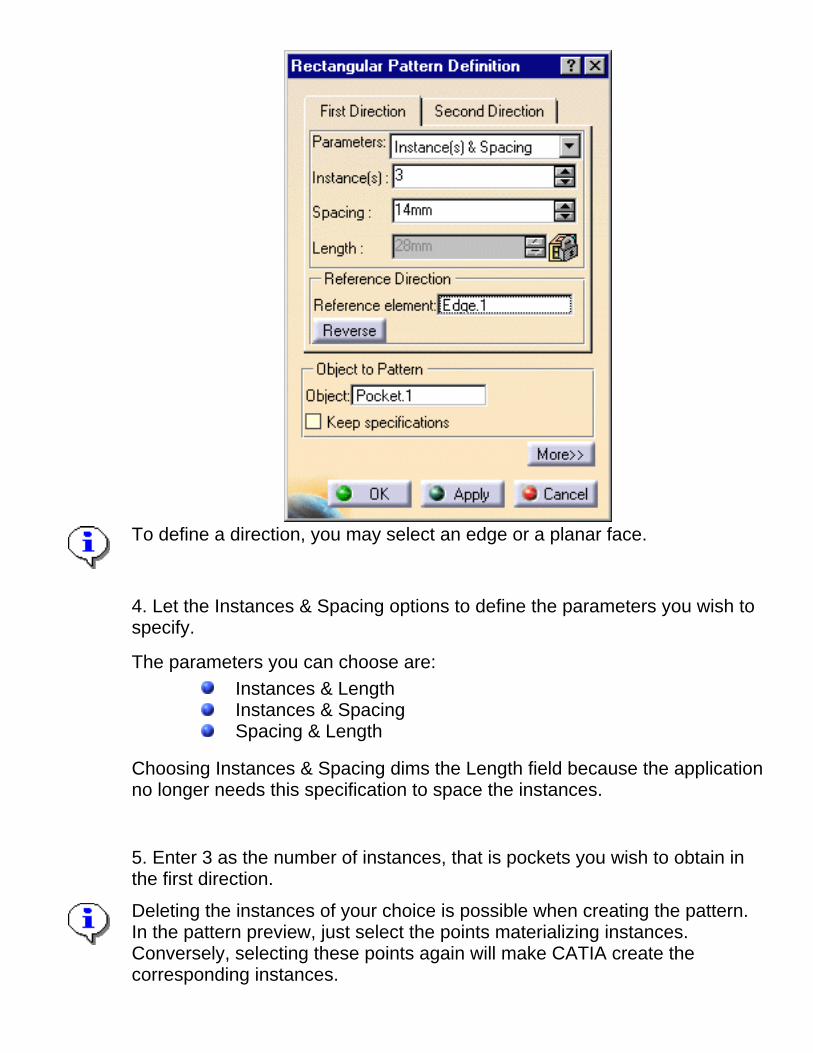
To define a direction, you may select an edge or a planar face.
4. Let the Instances & Spacing options to define the parameters you wish tospecify.
The parameters you can choose are:Instances & LengthInstances & SpacingSpacing & Length
Choosing Instances & Spacing dims the Length field because the applicationno longer needs this specification to space the instances.
5. Enter 3 as the number of instances, that is pockets you wish to obtain inthe first direction.
Deleting the instances of your choice is possible when creating the pattern.In the pattern preview, just select the points materializing instances.Conversely, selecting these points again will make CATIA create thecorresponding instances.

6. Define the spacing along the grid: enter 14 mm.
Defining the spacing along the grid and length of your choice would makethe application compute the number of possible instances and space them atequal distances.
7. Now, click the Second Direction tab to define other parameters.
Note that defining a second direction is not compulsory. Creating arectangular defining only one direction is possible.
8. Click the Reference element field and select the edge as shown below todefine the second direction.
9. Check the Reverse option to make the arrow point in the oppositedirection.
10. Let the Instances & Spacing option: enter 3 and 10 mm in theappropriate fields.

11. Examine the preview to makesure the pattern meets your needs.
Additional pockets will be alignedalong this second direction.
12. Click OK to repeat the pocketnine times.
This is the resulting pattern. You nowhave nine pockets.
13. Let's now edit the pattern to make it more complex: double-click thepattern to display the dialog box.

14. Click the More button to display the whole dialog box.
The options available makes it possible to position the pattern.
15. To modify the position of the pockets, enter -5 degrees as the rotationangle value.16. Click Apply.
You will notice that all pockets havemoved slightly:
17. Now, modify the location of theinitial pocket. To do so, enter 2 in theRow in Direction 1 field.
The application previews how thepattern will be moved. It will bemoved along the direction asindicated:

18. Finally, enter 2 in the Row inDirection 2 field.
The application previews how thepattern will be moved. It will bemoved along these two directionsdefined in steps 17 and 18:
19. Click OK.
The application has changed thelocation of all pockets. Only four ofthem remain on the pad.
CATIA Version 5 provides the capability of creating Cartesian patterns withvariable steps. To do so, define formulas. More explicitly, act on parametersi and j. For more information, refer to CATIA- Knowledge Advisor User'sGuide Version 5.

Circular PatternThis task will show you how to duplicate the original feature right away at the location of yourchoice using a circular pattern.
Make sure the item you wish to duplicate is correctly located in relation to the circularrotation axis.
Open the Circular_pattern.CATPart document from the \online\samples\part_designdirectory.
1. Click the Circular Pattern icon .
2.Select the pad you wish to copy.
The Circular Pattern Definition dialog box is displayed and the feature's nameappears in the Object field.
Checking the Keep specifications option lets you create instances with the limit defined forthe original feature. The example below shows you that the limit defined for the pad, that isthe "Up to surface" limit, applies to all instances. As the limiting surface is not planar, theinstances have different lengths.
But for our scenario, as the pad is going to be repeated on a planar surface, activating theKeep specifications option is meaningless.

The Parameters field lets you choose the type of parameters you wish to specifyso that CATIA will be able to compute the location of the items copied.
These parameters are:Instances & total angleInstances & angular spacingAngular spacing & total angleComplete crown
3. Set the Instances & Angular spacing options to define the parameters youwish to specify.4. Enter 7 as the number of pads you wish to obtain.
5. Enter 50 degrees as the angular spacing.
6. Click the Reference element field and select the upper face to determine therotation axis. This axis will be normal to the face.
Clicking the Reverse button reverses the direction.
Two arrows are then displayed on the pad.

To define a direction, you can select an edge or a planar face.
7. Define an angular space between each instance: enter 45 degrees.
If you modify the angular spacing, CATIA previews the result: arrows 1 and 2 are movedaccordingly.
8. Click OK.
CATIA previews the pattern: thepad will be repeated seven times.
9. Now, you are going to add a crown to your part. To do so, click the Crown Definitontab.10. Set the Circle & Circle spacing options to define the parameters you wish tospecify.
11. Enter 2 in the Circle(s) field.
12. Enter -10 mm in the Circle spacing field.
This figure may help you todefine your parameters:
13. Click OK.
These are your new instances:

14. Now, you are going to modify the position of the initial pad. Such a modification willaffect all instances too. To do so, click the More button to display the whole dialog box.
15. Enter 15 in the Rotation anglefield.
CATIA previews the rotation.
16. Click OK.
All instances are movedaccordingly.
Applying the Delete command on one instance deletes the whole pattern. However, deletingthe instances of your choice is possible when creating or editing the pattern. To do so,just select the points materializing instances in the pattern preview. Selecting these pointsagain will enable CATIA maintain the corresponding instances.

The scenario above does not show the use of the "Radial alignment of instances" option. Inaddition to performing the steps described, you could have use this option that allows you todefine the instance orientations.
The option is checked: all instances have the sameorientation as the original feature.
The option is unchecked: all instancesare normal to the lines tangent to thecircle.
CATIA offers the capability of creating polar patterns (for example, spiral patterns). To do so,define formulas using parameters i and j. For more information, refer to the CATIA-Knowledge Advisor User's Guide Version 5..

User PatternThe User pattern command lets you duplicate a feature (pad, pocket, shaft, groove, hole) as many times asyou wish at the locations of your choice. Locating occurences consists in specifying anchor points. Thesepoints are created in the Sketcher.
This task shows you how to duplicate a hole at the points defined in a same sketch plane.
Open the UserPattern.CATPart document from the \online\samples\part_design directory.
1. Click the User Pattern icon .
2. Select the hole you wish to duplicate
The User Pattern dialog box is displayed. The hole appears in the Object field.
Checking the Keep specifications option lets you create instances with the limit (Up to Next, Up to Last, Upto Plane or Up to Surface) defined for the original feature. In our scenario, the hole was created using theUp to Next option, but as the support for holes is a pad of an even thickness (20 mm), this makes the useof the option meaningless.
2. Select 'Sketch 4' in the specification tree. Thissketch includes the nine points you need to locatethe duplicated holes.

3. Actually, you just need seven points. Clickboth points you do not need to unselect them.
3. Click OK.
The seven holes are created at the points of the sketch. The specification tree indicates this creation.

MirrorMirroring a body consists in duplicating the body using a symmetry. You canselect a face or a plane about which you will mirror a body.
This task shows how to mirror a body.
Open the Mirror1.CATPart document from the \online\samples\part_designdirectory.
1. Select the face used as thereference.
2. Click the Mirror icon .
The Mirror Definition dialog boxappears.
3. Click OK to confirm the operation.
The body is mirrored and the originalelement is unchanged.
The specification tree mentions thiscreation.
Using a plane to mirror a body lets you obtain two independent portions ofmaterial in a same body. The following mirror is obtained by using plane zx asthe reference.


ScalingScaling a body means resizing it to the dimension you specify.This task shows how to scale a body in relation to a point.
Open the Scaling.CATPart document from the \online\samples\part_designdirectory.
1. Select the body to be scaled.
2. Click the Scaling icon .
The Scaling Definition dialog boxappears.
3. Select the reference point andenter 1.5 as the factor value.
4. Click OK.
The body is scaled accordingly. The specification tree indicates youperformed this operation.

You can also resize a body in relation to a face or plane. In the example below,the upper face is the reference element and the factor value is 1.5. You obtainan affinity.

Displaying and Editing PropertiesThis section discusses the ways of accessing and editing information concerning parts, bodiesand features. The data you access varies depending on the element you select, but youalways access it using the Edit -> Properties command.
Displaying and Editing PartsProperties
Displaying and Editing BodiesProperties
Displaying and EditingFeatures Properties

Displaying and Editing the PartProperties
Gathered in a same dialog box, the part properties consist of different indicationsyou will have sometimes to refer to. This task explains how to access and ifneeded, edit this information.
1. Select the part in thespecification tree.
2. Select the Edit->Properties command or select the Properties commandon the contextual menu.
The Properties dialog box displays, containing the following tabs dealingwith the part:ProductMass
3. The Product tabcontains editable fields.
Enter a new name for thepart in the Part Numberfield.
The new name appearsin the specification tree.
4. The other fields allow you to freely describe the part. Enter theinformation describing your part in the context of your company.5. Set the Source option. You can choose between Unknown, Madeor Bought.

6. Now, clicking the Mass tab displays technical information youcannot edit:Note however that you can edit the density of a part byapplying a new material. To know how to apply materials to parts,please refer to CATIA- Real Time Rendering User's Guide Version 5.
7. Once you are satisfied with your operation, click OK to confirm theoperation and close the dialog box.

Displaying and Editing BodiesProperties
This task shows how to display and edit bodies properties. To know how to editthe graphic properties of a body refer to the Infrastructure documentation,Displaying and Editing Graphic Properties.
1. Select the body in the specification tree.
2. Select the Edit->Properties command or select the Properties commandon the contextual menu.
The Properties dialog box displays, containing two tabs concerning bodies:Feature propertiesGraphic

3. In the Feature properties tab, only the name of the feature is editable.Enter Body1 in the Name field. This name is editable if the part is not readonly.
The new name appears in the specification tree.4. Click the Graphic tab to change the color of the body. To havedetails about how to change graphic properties, please refer to CATIA- Infrastructure User's Guide Version 5.5. Click OK.
CATIA takes these modifications into account and displays the new bodyname.

Displaying and Editing FeaturesProperties
This task shows how to display and edit the properties of a pad.
1. Select the feature in the specification tree, that is pad2.
2. Select the Edit->Properties command or select the Properties commandon the contextual menu.
The Properties dialog box displays, containing these tabs:Feature PropertiesMechanicalGraphic
3. Enter a new name for the pad in the Name field.
This field is not available if the file is read only.
4. Click Apply to display the new name in the specification tree.
5. Click the Mechanical tab to access other information.
The Mechanical tab displays the status of the pad.
The following attributes characterize features:

Deactivated: checking thisoption will prevent CATIAfrom taking deactivatedfeatures into account duringan update operation.To Update: indicates thatthe selected feature is to beupdated.Unresolved: indicates thatthe selected feature has notbeen computed by theapplication.
You cannot control the lasttwo options. The symboldisplayed in front of eachattribute may appear in thespecification tree in somecircumstances.
For more about updates,refer to Updating Parts.
6. Check the Deactivated option to deactivate the pad.
You will note that a new frame is displayed, providing additionalinformation. CATIA actually warns you that the operation will affect the onlychild of the pad, that is the hole.
In certain cases, features may have several children. What you need to dois select the children in the list and check the first option if you wish todeactivate them or just check the second option to deactivate all of thechildren affected.

7. Click the Graphic tab to change the color of the feature. To have detailsabout how to change graphic properties, please refer to CATIA-Infrastructure User's Guide Version 5.
8. Press OK to confirm the operation and close the dialog box.
The geometry no longer shows the deactivated features and thespecification tree displays red brackets on them to symbolize their status.


Modifying PartsEditing a feature or a sketch is a simple operation but you need to know some details about the way of doing it.
There are many ways of modifying parts. You can redefine parameters before or during updates or use theReorder capability to rectify design mistakes.
But prior to modifying parts, you can use commands that facilitate the modifications you need to perform. Forexample, you can view the genealogical relationships between the different components of a part. You can evenaccess bodies locally.
In a nutshell, this section deals with the different modifications you can perform but it also describes how you candelete features.
Redefining Feature Parameters Reordering Features Parent and Children
Scanning the Part and Defining LocalObjects Updating Parts Deleting Features

Editing Parts, Bodies and FeaturesEditing a part may mean for example modifying the density of the part (See Displayingand Editing Properties ), but most often editing consists in modifying the featurescomposing the part. This operation can be done at any time.
There are several ways of editing a feature. If you modify the sketch used in thedefinition of a feature, CATIA will take this modification into account to recompute thefeature: in other words, associativity is maintained.
Now, you can also edit your features through definition dialog boxes in order toredefine the parameters of your choice.
Redefining Feature ParametersThis task shows how to edit a draft and a pad. The process described here isvalid for any other feature to be edited.
Open the Edit.CATPart document from the \online\samples\part_designdirectory.
1. Double-click the draft to be edited (in the specification tree or in thegeometry area). For more abour draft, refer to Basic Draft.
The Draft Definition dialog box appears and CATIA shows thecurrent draft angle value. Generally speaking, CATIA always showsdimensional constraints related to the feature you are editing.Concerning sketch-based features, CATIA also shows the sketchesused for extrusion as well as the constraints defined for thesesketches.
Instead of double-clicking the element you wish to edit, you can also click thiselement and select the XXX.object -> Definition... command which will displaythe edit dialog box.

2. Enter a new draft angle value.
3. Click OK.
This is your new feature:
4. Now, double-click the pad.
The Pad Definition dialog box appearsand CATIA shows the pad only, not thenext operation.
You will notice that the pad was createdin symmetric extent mode and thatCATIA displays information about theinitial profile.5. Enter a new length value.
6. Uncheck the Mirrored extent option.
7. Enter a length value for the second limit in the Length field.
CATIA previews the new pad to be created.
8. Click OK.
The modifications are taken intoaccount. Your part now looks like this:

You can also access the parameters you wish to edit in the following way:1. Select the feature in the specification tree and use the feature.n object-> Edit Parameters contextual command.
You can now view the feature parameters in the geometry area.
2. Double-click the parameter of interest.
A small dialog box appears displayingthe parameter value:
3. Enter a new value and click OK.

Reordering FeaturesThe Reorder capability allows you to rectify design mistakes. This task showshow to reorder, that is move a pad.
Open the Reorder.CATPart document from the \online\samples\part_designdirectory.
1. Your initial data consists of a pad that was mirrored and a second padcreated afterwards. As the order of creation is wrong, you are going toreorder the second pad so as to mirror the whole part. Position your cursoron Pad.2. and select Edit -> Pad.2 object -> Reorder...
The Feature Reorder dialog boxappears.
2. Select Pad.1 to specify thenew location of the feature.
This name appears in the After:field.

3. Click OK.
The part rebuilds itself. The mirror feature appears after the creation of thesecond pad, which explains why this second pad is now mirrored.

Parent and ChildrenThe Parent and Children command enables you to view the genealogical relationships betweenthe different components of a part. If the specification tree already lets you see the operations youperformed and respecify your design, the graph displayed by the Parent and Children capabilityproves to be a more accurate analysis tool. Before deleting a feature, we recommend the use ofthis command.
Open the Parent.CATPart document from the \online\samples\part_design directory.
1. Select the feature ofinterest, that is Pad1.
2. Select the Tools -> Parent / Children... command (or the Parent/Children contextualcommand).
A new window appears containing a graph. This graph shows the relationships between thedifferent elements constituting the pad previously selected.

3. Position the cursor on Pad 1 and select the Show All Children contextual command.
You can now see thatSketch 2 and Sketch 3have been used tocreate two additionalpads.
4. Now, selectEdgeFillet1 in the graph.
The applicationhighlights the fillet in thespecification tree, in thegraph and in thegeometry area.
5. Position the cursor on EdgeFillet1 and select the Show Parent and Children contextualcommand.
EdgeFillet1 is now the feature whose relationships you wish to see. Pad1 and Draft.1 are twoparents.
6. To see all parents, position the cursor on EdgeFillet1 and select the Show All Parentscontextual command.
The sketch upon which the pad and therefore the edge fillet depend is displayed.
7. Once you have got the useful information, click OK to quit the command.
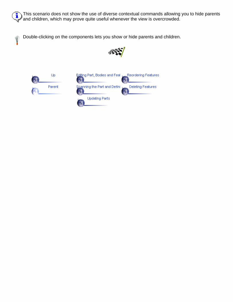
This scenario does not show the use of diverse contextual commands allowing you to hide parentsand children, which may prove quite useful whenever the view is overcrowded.
Double-clicking on the components lets you show or hide parents and children.

Scanning the Part and Defining LocalObjects
In Part Design, you can access, view and operate all features or bodies locally.The Scan and Define in Work Object capability allows you to design partfeatures without taking the complete part into account.
This task shows how to scan the part and define a local object.
Open the Active.CATPart document from the \online\samples\part_designdirectory.
1. Select the Edit -> Scan or Define in Work Object... command.
The Scan toolbar appears enabling you to navigate through the structureof your part.
You actually need to click the buttons allowing you to move from one localfeature to the other. Sketches are not taken into account by the command.

2. Click the Backwards button tomove to the previous feature, that isa pocket.
The application highlights the featurein question in the specification treeas well as in the geometry area.
3. Click the Backwards arrow once more to move to the previousfeature, that is a mirror.
4. Now that you have accessed thefeature of your choice, that is themirror, isolate it from the current partby clicking the Exit button.
In the geometry area, the applicationdisplays the local object only. In thespecification tree, this local object isunderlined.
You are now ready to work on thisfeature.

.
Defining a feature as local without scanning the whole part is possible using theDefine in Work Object contextual command on the desired feature.

Deleting FeaturesWhenever you will have to delete geometry, you will not necessarily have to delete the elements used to create it.CATIA lets you define what you really want to delete.This task shows how to delete a sketch on which geometry has been defined and what this operation involves.
Open the Delete.CATPart document from the \online\samples\part_design directory.
1. Select the rectangle you wish to delete.
2. Select the Edit -> Delete... commands.The Delete dialog box is displayed, showing the element to be deleted and two options.
Delete exclusive parents: deletes the geometry on which the element was created. Thisgeometry can be deleted only if it is exclusively used for the selected elementChildren: deletes the geometry based upon the element to be deleted, in other words,dependent elements
Here, the first option cannnot be used because the rectangle has no parents.3. Click More.
Additional options and the elements affected by the deletion are displayed. If you can delete the sketch, you canalso replace it with another element.

4. Select Sketch4, that is the hexagon to replace Sketch 2 .
This operation is now displayed in the dialog box.5. Click OK.
The sketch is deleted as well as its children : two pads one of which is filleted.
A Few Notes About DeletionDeleting Features Built upon Dress-up Features
If you delete a feature (dress-up or not) previously used to create a dress-up feature, the dress-upfeature is recomputed.In this example, thickness was added to the pad, then material wasremoved from the whole part using the shell capability. In otherwords, the existence of the shell depends upon the existence ofthe thickness.
You will notice that only the thickness has been deleted. CATIAkeeps the shell feature.
Keep in mind you can apply the Undo command if you inadvertently deleted a feature.You are not allowed to delete a profile used to define a feature, unless you delete the profile to constructanother one.Patterns
Concerning patterns, applying the Delete command on one instance deletes the whole pattern.
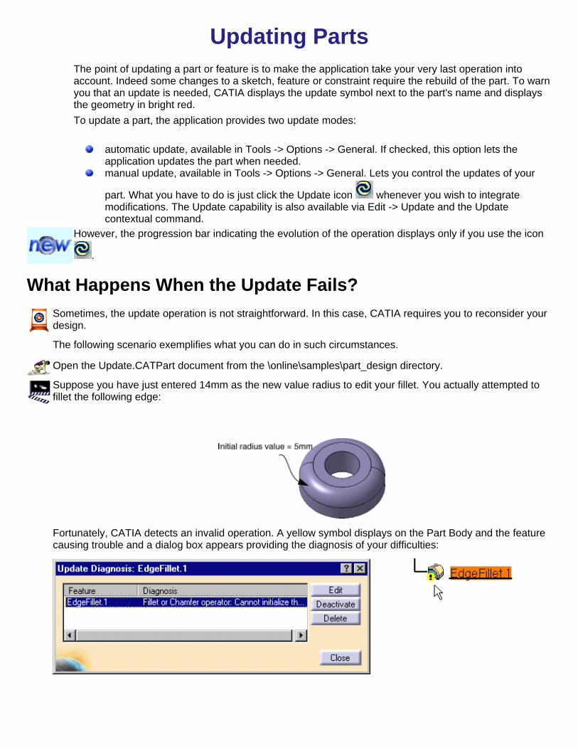
Updating PartsThe point of updating a part or feature is to make the application take your very last operation intoaccount. Indeed some changes to a sketch, feature or constraint require the rebuild of the part. To warnyou that an update is needed, CATIA displays the update symbol next to the part's name and displaysthe geometry in bright red.To update a part, the application provides two update modes:
automatic update, available in Tools -> Options -> General. If checked, this option lets theapplication updates the part when needed.manual update, available in Tools -> Options -> General. Lets you control the updates of your
part. What you have to do is just click the Update icon whenever you wish to integratemodifications. The Update capability is also available via Edit -> Update and the Updatecontextual command.
However, the progression bar indicating the evolution of the operation displays only if you use the icon
.
What Happens When the Update Fails?Sometimes, the update operation is not straightforward. In this case, CATIA requires you to reconsider yourdesign.
The following scenario exemplifies what you can do in such circumstances.
Open the Update.CATPart document from the \online\samples\part_design directory.
Suppose you have just entered 14mm as the new value radius to edit your fillet. You actually attempted tofillet the following edge:
Fortunately, CATIA detects an invalid operation. A yellow symbol displays on the Part Body and the featurecausing trouble and a dialog box appears providing the diagnosis of your difficulties:

2. What you need to do is click the name of the fillet causing trouble.
Three options are then available. You canedit the featuredeactivate the featuredelete the feature
3. Click the Edit button to modify the fillet.
The Edge Fillet Definition dialog box appears to let you enter acorrect radius value.
4. Enter 8 mm.
5. Click OK to confirm the operation.
The fillet is now valid:

Replacing ElementsThis theme shows you how to modify features by replacing surfaces, faces, planes orsketches used for defining them.
Replacing aSurface Replacing a Sketch Changing Sketch
Supports

Replacing a SurfaceThe Replace command lets you replace sketches, faces, planes and surfaces byother appropriate elements.
This task shows you how to replace a surface used for creating geometry withanother surface. The operating mode described here is valid for replacingsketches (for an example, see Replacing a Sketch), faces and planes too.Open the Replace1.CATPart document from the \online\samples\part_designdirectory.1. Select Extrusion1, that is the red surface used for trimming both the pocketand the hole.
2. Right-click to display the contextual menu and select the Replace... command.
The Replace dialog box is displayed, indicating the name of the surface to bereplaced.3. Select Extrusion 2 as the replacing surface. Extrusion 2 now appears in theWith field of the dialog box.

4. Check the Delete option to delete Extrusion1.
5.Click OK to confirm the operation.
The pocket and the hole arenow trimmed by Extrusion 2.Extrusion 1 has been deleted.

Replacing a SketchThe Replace command lets you replace sketches, faces, planes and surfaces byother appropriate elements.
This task shows you that features based on sketches can have their sketchesreplaced by new ones.Open the Replace.CATPart document from the \online\samples\part_designdirectory.1. Select Sketch2, that is the square used in the definition of the blue filleted pad.
Note that this pad has been copied eight times. This is the result of the use of theRectangular Pattern command. For more about this command, refer toRectangular Pattern.
2. Right-click to display the contextual menu and select the Replace... command.
The Replace dialog box is displayed, indicating the name of the sketch to bereplaced.3. Select sketch3 as thenew sketch. Sketch 3 nowappears in the With field ofthe dialog box.

Sketch 3 is an hexagoncreated in the Sketcher.
Note that If you wish to, youcan delete Sketch 2 bychecking the Delete option.
4. Click OK to confirm theoperation.
A new pad based on sketch 3 is created. The pattern is updated too, and thefillets are maintained.
Sketch3 is now displayed below Pad 2, that is the original pad, in thespecification tree and Sketch2 is still available.
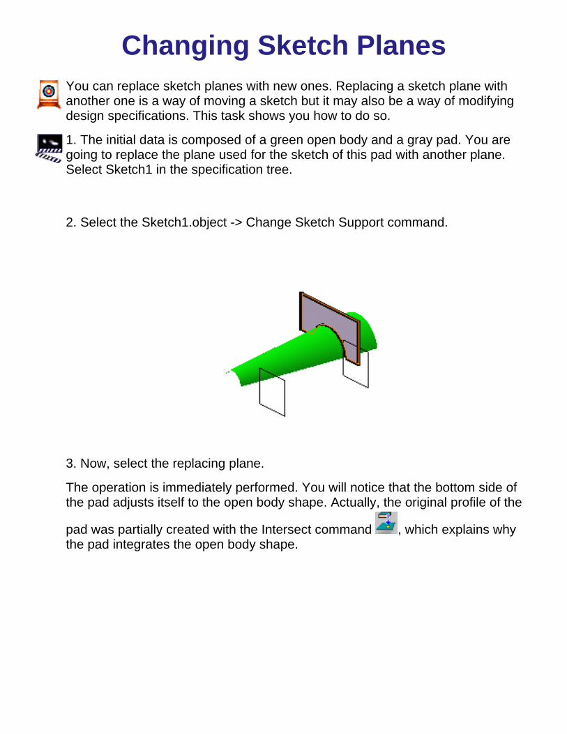
Changing Sketch PlanesYou can replace sketch planes with new ones. Replacing a sketch plane withanother one is a way of moving a sketch but it may also be a way of modifyingdesign specifications. This task shows you how to do so.
1. The initial data is composed of a green open body and a gray pad. You aregoing to replace the plane used for the sketch of this pad with another plane.Select Sketch1 in the specification tree.
2. Select the Sketch1.object -> Change Sketch Support command.
3. Now, select the replacing plane.
The operation is immediately performed. You will notice that the bottom side ofthe pad adjusts itself to the open body shape. Actually, the original profile of the
pad was partially created with the Intersect command , which explains whythe pad integrates the open body shape.


Setting Constraints
CATIA Version 5 lets you set geometrical and dimensional constraints on various types of elements in the 3Dgeometry area.
This section shows you how to use both constraint commands:
Constraint defined in Dialog Box .
Constraint
and how to modify them. Note also that you can customize symbols dedicated to constraints. To have details aboutit, please refer to Customizing Constraints.
Setting Constraints Setting Constraints Defined in DialogBox Modifying Constraints

Setting Constraints in the 3D Area
3D area constraints are defined by means of the commands.Depending on the creation mode chosen for creating wireframe geometry andsurfaces (see CATIA Wireframe and Surface User's Guide), constraints set onthese elements may react in two ways. You create measures if support elementswere created with the Datum mode disactivated. Conversely, you createconstraints with no links to the other entities that were used to create them ifyou constrain datums. For more about datums, please refer to Creating Datums.
This task shows you how to set a distance constraint between a face and aplane.
1. Select the face you wish to constrain.
2. Select the plane.
3. Click the Constraint icon .
CATIA detects the distance value between the faceand the plane. Moving the cursor moves thegraphic symbol of the distance.4. Click where you wish to position the constraintvalue.
Now, if you wish to set another constraint between theplane and another face, CATIA will create a measure.Creating a measure means that each time CATIAintegrates modifications to the geometry, this measurereflects the changes too.
The measure is displayed in brackets.
Likewise, you cannot constrain a distance between two faces. In the examplebelow, CATIA creates a measure constraint between the faces, not a drivingconstraint.

To know how to modify a constraint, refer to Modifying Constraints.

Setting Constraints Defined in DialogBox
This task shows you how use this constraint command which detectspossible constraints between selected elements and lets you choose theconstraint you wish to create.
1. Multiselect the elements you wish to constrain, that is both faces asshown.
2. Click the Constraint Defined in Dialog Box icon .
CATIA detects three possible constraints you can set between the faces:DistanceAngleFix
The other constraints are grayed out indicating that they cannot be set for theelements you have selected.

3. Check the Distance option and click OK to confirm.
The distance constraint is created.
To know how to modify a constraint, refer to Modifying Constraints.

Modifying Constraints
Editing Constraints
You can edit constraints by:
double-clicking on the desired constraints and modify related data in the Constraint Definition dialog box thatdisplays.
selecting the desired constraints and use the XXX.N.object -> Definition.. contextual command...
...to display the Constraint Definition dialog box and modify related data.
Renaming Constraints
You can rename a constraint by selecting it and by using the XXX.N.object -> Rename parameter contextualcommand.... In the dialog box that appears, you just need to enter the name of your choice.
Deactivating or Activating Constraints
You can deactivate a constraint by selecting it and by using the XXX.N.object -> Deactivate contextual command.Deactivated constraints appear preceded by red brackets.
Conversely, to activate a constraint, use the Activate contextual command.


Advanced Tasks
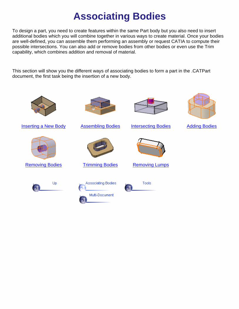
Associating BodiesTo design a part, you need to create features within the same Part body but you also need to insertadditional bodies which you will combine together in various ways to create material. Once your bodiesare well-defined, you can assemble them performing an assembly or request CATIA to compute theirpossible intersections. You can also add or remove bodies from other bodies or even use the Trimcapability, which combines addition and removal of material.
This section will show you the different ways of associating bodies to form a part in the .CATPartdocument, the first task being the insertion of a new body.
Inserting a New Body Assembling Bodies Intersecting Bodies Adding Bodies
Removing Bodies Trimming Bodies Removing Lumps

Inserting a New BodyThis task shows you how to insert a new body into the part.
1. To add a body to the part,select the Insert -> Bodycommand.
CATIA displays this new bodyin the specification tree. It isunderlined, indicating that it isthe active body.
2. Now, let's construct this new body: for example, sketch a circle on one ofthe part faces.
3. Leave the Sketcher and extrude this circle to create a pad.
Eventually, the specification tree looks like this:

You will notice that the Part body and Body1 are autonomous. The operationsyou would accomplish on any of them would not affect the integrity of the otherone. Now, if you wish to combine them, refer to the following tasks which showthe different ways of attaching bodies.

Adding BodiesThis tasks illustrates how to add a body to a part.
Open the Add.CATPart document from the \online\samples\part_designdirectory.
1. This is your initial data: the pads are independent. To perform the
addition, you need to select Body.1. and click the Add icon (or selectthe Edit -> Body.1.object -> Add... command).
The result is immediate. However, if the specification tree iscomposed of several bodies, a dialog box displays to let youdetermine the second body you wish to use. By default, theapplication proposes to add the selected body to the Part body.
The specification tree and the part now look like this:

You will note that both pads keep their original colors.

Assembling BodiesAssembling is an operation integrating your part specifications. This task showsyou two assemble bodies to let you see how the resulting parts look differentdepending on your specifications.
Open the Assemble.CATPart document from the \online\samples\part_designdirectory.First, you are going to assemble a pocket to the Part Body. You will note that asthis pocket is the first feature of the body, material has been added (see BasicPockets , key point).
1. To assemble them, you need to select Body 2 and click the Assemble
icon (or select the Edit -> Body2.object -> Assemble... command).

The Assemble dialog box displays tolet you determine the assembly youwish to perform. By default, CATIAproposes to assemble the selectedbody to the Part body, and displays thename of the last feature of the Partbody in the After field.
2. As you wish to perform this operation, click OK.
During the operation, CATIA retrieves the material defined by the pocketfrom the Part body.
This is your new Part body:
3. Now delete the assemble operation to go back to the previous state. Youare going to perform a new assemble operation.
4. Select Body 2 and the Edit -> Body2.object -> Assemble command.
The Assemble dialog box displays again.
5. Select Body1 in the specification tree to edit the After field. Pad2appears in the field, indicating that you are going to assemble Body2 toBody1.

6. Click OK.
The material defined by the pocket from Body1has been retrieved duringthe operation.

Removing BodiesThis tasks illustrates how to remove a body from a part.
Open the Remove.CATPart document from the \online\samples\part_designdirectory.
1. The part is composed of two pads. To remove Body 1 from the Partbody, select Body.1
2. Click the Remove icon (or select the Edit -> Body.1.object ->Remove... command).
The result is immediate. However, if the specification tree is composed of severalbodies, a dialog box displays to let you determine the second body you wish touse. By default, the application proposes to remove the selected body from thePart body.
The cylinder is removed from the Part body:


Intersecting BodiesThe material resulting from an intersection operation between two bodies is thematerial shared by these bodies. This tasks illustrates how to compute twointersections.
Open the Intersect.CATPart document from the \online\samples\part_designdirectory.This is your initial data: the three pads belong to distinct bodies.
7. To compute the intersection between the Part body and Body 2, selectBody.2.
8. Click the Intersect icon (or select the Edit -> Body.2.object ->Intersect... command).
The Intersect dialog box displays to let you determine the second body youwish to use. By default, the application proposes to intersect the selectedbody to the Part body.

9. As you wish to perform thisoperation, click OK.
CATIA computes the intersectionbetween the two bodies.
The Part body now looks like this:
10. Now delete the intersection to go back to the previous state. You aregoing to create a new intersection.
11. Position your cursor on Body 2 and select the Edit -> Body2.object ->Intersect contextual command to display the Intersect dialog box.
12. Select Body1 in the specification tree to edit the After field. Pad2appears in the field, indicating that you are going to compute theintersection between Body2 and Body1.

13. Click OK. Body1 now looks like this:

Trimming BodiesApplying the Union Trim command on a body entails defining the elements to be keptor removed while performing the union operation.
The following rules are to be kept in mind:
Concretely speaking, you need to select the two bodies of interest and specify thefaces you wish to keep or remove. This section provides two parts you can obtainusing the Union Trim capability: a flange and a stiffener.
FlangeThis tasks illustrates how to create a flange using the Union Trim capability.
Open the Union_Trim1.CATPart document from the \online\samples\part_designdirectory.
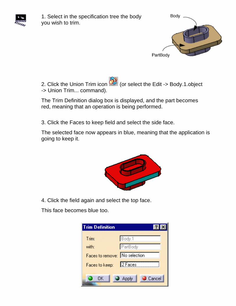
1. Select in the specification tree the bodyyou wish to trim.
2. Click the Union Trim icon (or select the Edit -> Body.1.object-> Union Trim... command).
The Trim Definition dialog box is displayed, and the part becomesred, meaning that an operation is being performed.
3. Click the Faces to keep field and select the side face.
The selected face now appears in blue, meaning that the application isgoing to keep it.
4. Click the field again and select the top face.
This face becomes blue too.
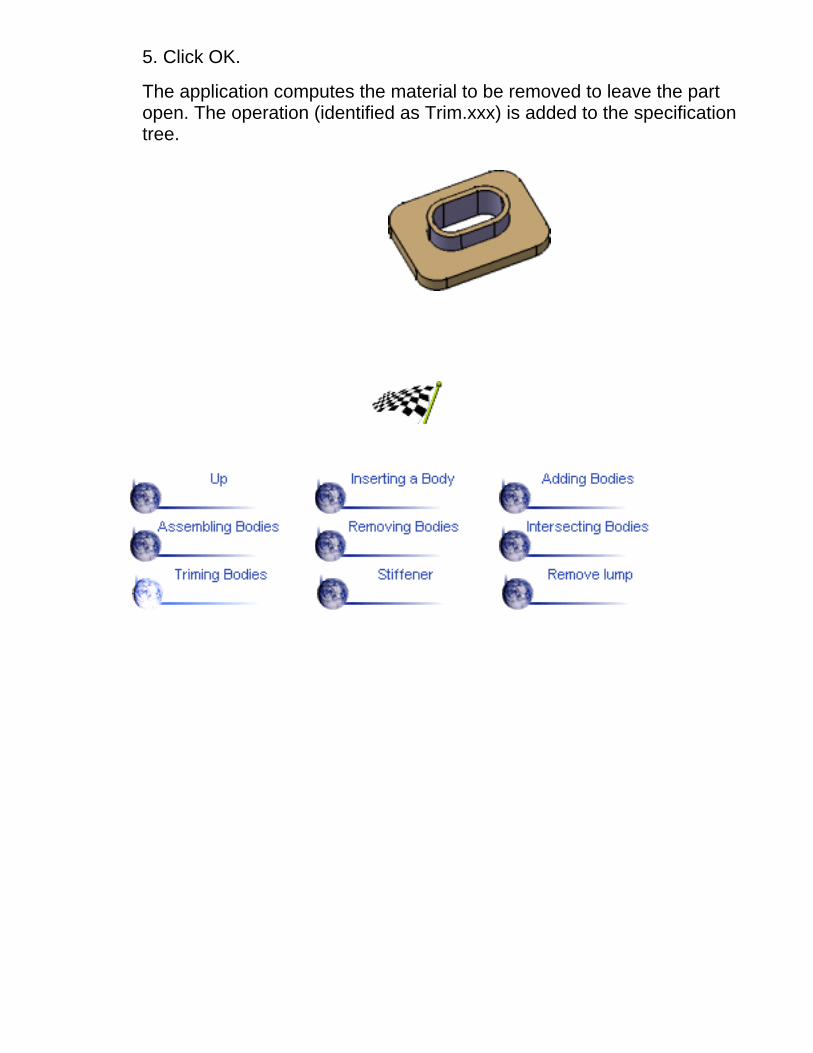
5. Click OK.
The application computes the material to be removed to leave the partopen. The operation (identified as Trim.xxx) is added to the specificationtree.

StiffenerThis tasks illustrates how to create a stiffener using the Union Trim capability.
Open the Union_Trim2.CATPart document from the \online\samples\part_designdirectory.
1. Select in the specification treethe body you wish to trim.
2. Click the Union Trim icon (or select the Edit -> Body1.object ->Union Trim... command).
The Trim Definition dialog box appears:
3. Click the Faces to remove field and select the face as shown.
The selected face now appears in pink, meaning that it will be removedduring the Trim operation.

4. Click OK.
The stiffener is created.

Keeping and Removing FacesThe Remove Lump command lets you reshape a body by removing material. Toremove material, either you specify the faces you wish to remove or conversely,the faces you wish to keep. In some cases, you need to specify both the faces toremove and the faces to keep.
This task illustrates how to reshape a body by removing the faces you do notneed. Depending on the faces you select for removal, you will obtain two distinctbodies.Open the Remove_Lump.CATPart document from the\online\samples\part_design directory.
1. Select the body you wish to reshape, that is Part Body.
2. Click the Remove Lump icon (or select the Part Body object ->Remove Lump... contextual command).
The Remove Lump dialog box appears.The application prompts you to specifythe faces you wish to remove as well asthe faces you need to keep.
3. Click the Faces to remove field andselect the face as shown.
The selected face now appears in pink,meaning that it will be removed duringthe operation.

4. Click OK.
The new body looks like this :
5. Now, double-click RemoveLump in the specification tree toedit it.
6. In the Dialog box that appears,click the Faces to remove fieldand select the face as shown.
This face appears in pink.
The faces selected as the faces to be kept are displayed in blue.
5. Click OK.
The new body looks like this :

ToolsThis theme shows you how to measure distances and angles between geometricalentities or between points.It also explains how to measure the properties associated toa selected item.
Draft Analysis Curvature Analysis
Measuring Minimum Distancesand Angles Measuring Elements

Performing a Draft AnalysisThis task explains how to detect if the part you drafted will be easily removed fromthe associated mold. For more about drafts, please refer to Basic Draft.
The discretization option should be set to a maximum (the 3D Accuracy -> Fixedoption should be set to 0).
Prior to analyzing the draft, you need todefine a direction by using the compass.This direction is supposed to be thepulling direction used for removing thepart from its mold.
1. Drag the compass and drop it ontoplane zx.
Y axis always indicates the direction ofanalysis.
Once the compass is snapped to theplane, you can begin to start using theDraft Analysis command.
2. Click the Draft Analysis icon .
3. Select the part. Selecting a face is enough for taking the whole part into account.To improve the display, drag the compass away from the plane and drop it.
The Draft Analysis dialog box is displayed, and the analysis is visible on the part.The part has three colors: red, light blue and green. Each color is defined in thedialog box. Each color is associated to a range of draft angle values, as specified inthe fields below. The values range from -20 to 20 degrees. However, these colorsdefined for minimum and maximum ranges apply to values inferior to -20 or superiorto 20 degrees too.

4. You can customize these colors. For example, double-click the light blue arrow todisplay a color palette you are going to use for creating your own yellow.
5. In the palette that appears, drag the cross inside the spectrum to instantaneouslychange the color in the small box below the spectrum. Drag the cross so as toobtain a yellow color.
6. If needed, move the arrow up or down to vary the brightness of the custom colorand click OK to create your own color.
The Color palette closes and the Draft Analysis displays the yellow color instead ofthe light blue one.
To get the most out of colors, use the View + Lighting capability, as explained in theCATIA- Infrastructure User's guide Version 5.
7. Select the dark blue arrow and move it down to remove the associated dark bluefield.
The dialog box now displays three colors only.

8. Keep the Sharp left option. The different displays for the color range are:linear,sharp left,sharp center (reserved for surfaces, see the CATIA FreeStyle Shaper &Optimizer User's Guide),sharp right (reserved for surfaces, see the CATIA FreeStyle Shaper &Optimizer User's Guide)
The linear option is available too for analyzing drafted faces. Depending on thecomplexity of the part, it may sometimes be more efficient.
9.Enter 2.0 in the field associated to the green arrow. Note that you can manipulatethe draft angle values by clicking on the arrows too. This value is the minimum draftangle value which makes the removal of the part possible.
The dialog box now looks like this...
.. and the part like this:

Using the values and colors set and the direction defined at the beginning of thistask, you can analyze the results as follows:
- the red areas cannot be removed from the mold. These areas are assigned a draftangle value set between -90 and 0 degrees.
- the yellow areas cannot be removed from the mold either. These areas areassigned a draft angle value set between 0 and 2 degrees.
- the green areas can be removed from the mold. These areas are assigned a draftangle value set between 2 and 90 degrees.
10. Check the On the fly analysis option and move the pointer over a yelow area.
Arrows are displayed under the pointer, identifying the normal to the face at thepointer location (green arrow). As you move the pointer over the surface, the normaldisplay is dynamically updated.
The displayed value indicates the angle between the draft direction and the normalto the surface at the current point.

If you click the green arrow (Normal) you can invert it. You can therefore obtain theopposite result.
If you click the red arrow, it freezes the location for the arrow allowing generalmanipulations according to the compass.11.Once you have finished analyzing the draft, click Close. Otherwise click Reset tocome back to default values for the color range.

Curvature AnalysisThis task explains how to how to analyze the Gaussian curvature of a body.
The visualization mode should be set to Shading with Texture and Edges, andthe discretization option should be set to a maximum (the 3D Accuracy -> Fixedoption should be set to 0).
1. Select a body.
2.Click the Curvature Analysis icon .
The Curvature Analysis dialog box is displayed, and the analysis is visible on theselected element.
3.Choose the linear option from the dialog box.Available options to display the color range are:
linear,sharp left,sharp center,sharp right.
The values are ranging from 0 to 1, corresponding to the minimum and maximumGaussian curvature respectively.4.Modify the values in the color range to highlight specific areas of the selectedface.To do this, click and drag the arrows delimiting the colors, or directly enter thevalues.5.Click Close to exit the command, or reset to come back to default values for thecolor range.

Measuring Minimum Distances &Angles between Geometrical Entities
or Points
This task explains how to measure distances and angles between geometricalentities (surfaces, edges, vertices and entire products) or between points.
To get the most out of this tool, set the Render Style to Shading with Edges.
For example, open the Measure_Between.CATPart document from the\online\samples\part_design directory.
1. Click the Measure Between icon .
The Measure Between dialog box appears.
2.Set the desired measure type in the Measure type drop-down list box

Defining measure types:Between (default type): measures distance and angle betweendefined reference and target itemsChain: sets the target item as the reference item for the nextmeasureFan: fixes the reference item selection so that you alwaysmeasure from this item
3. Set the desired measure mode in the Target and Referencedrop-down list boxesDefining measure modes:
Any geometry (default mode): measures distances and anglesbetween defined geometrical entities (points, edges, surfaces,etc.)Any geometry, infinite: measures distances and anglesbetween planar faces mapped onto infinite planes and straightline segments mapped onto infinite lines. For all otherselections, the measure mode is the same as any geometryPoint on geometry: measures distances and angles betweenpoints selected on defined geometrical entitiesPoint only, Edge only, Surface only: measures distances andangles between points, edges and surfaces respectively.Dynamic highlighting is limited to points, edges or surfacesand is thus simplified compared to the Any geometry mode.Intersection: measures distances and angles betweenintersection points between two edges or an edge and asurface. In this case, two selections are necessary to definetarget and reference itemsEdge limits: measures distances and angles betweenendpoints or midpoints of edges. Endpoints only are proposedon curved surfaces.Arc center: measures distances and angles between thecenters of arcsCoordinate: measures distances and angles betweencoordinates entered for target and/or reference items
4. Click to select a surface, edge or vertex.
The appearance of the cursor haschanged to reflect the measure commandyou are in. A number (1 for the referenceitem and 2 for the target item) also helpsyou identify where you are in yourmeasure.

Dynamic highlighting as you move your cursor over surfaces, facesand vertices helps you locate the reference and target items.
5. Click to select another surface, edge or vertex.
A line representing the minimum distance vector is drawn between the selecteditems in the geometry area. Appropriate distance values are displayed in thedialog box.

The overall minimum distance as well as distance vector componentsbetween the selected items and x,y,z coordinates of points betweenwhich the minimum distance was measured are given in the MeasureBetween dialog box.
The number of decimal places is controlled by the DMU Navigator tab in theOptions dialog box (Tools -> Options, Product).
6. If necessary, adjust the presentation of the measure. You can move thelines and text of the measure
7. Select another reference item
8. Set the Measure type to Fan to fix the reference item selection sothat you can always measure from this item
9. Select the target item
10. Select another target item
Customizing Your Measure:
You can, at any time, customize the display of the results in both thegeometry area and the dialog box. To do so, click Customize... in theMeasure Between dialog box and set your display in the MeasureBetween Customization dialog box. By default, all results aredisplayed.

11. Click Close.

Measuring ElementsThis task explains how to measure the properties associated to a selected item(points, edges and surfaces)To get the most out of this tool, set the Render Style to Shading with Edges.
For example, open the Measure_Between.CATPart document from the\online\samples\part_design directory.
1. Set View -> Render Style to Shading with Edges
You cannot use this command, if Shading only is selected.
2. Click to select the desired item.
3. Click the Measure Item icon.
The appearance of the cursor has changed to reflect the measurecommand you are in.
Dynamic highlighting as you move your cursor over objects helps you locate thereference item.
The dialog box is updated.

The dialog box gives information about the selected item, in our case a surface.The center of gravity of the surface is visualized by a point. In the case of nonplanar surfaces, the center of gravity is attached to the surface over theminimum distance.
5. Click Customize... in the Measure Item dialog box to see theproperties the system detects for the various types of item you canselect
Customizing Your Measure:
You can, at any time, customize the display of the results in both the geometryarea and the dialog box. To do so, click Customize... in the Measure Item dialogbox and set your display in the Measure Item Customization dialog box. Bydefault, all results are displayed.

6. Try selecting other items to measure associated properties
The system detects whether the edge is a line, curve or arc, taking modelaccuracy into account. If a line or curve is detected, the dialog box indicates thelength as well as X, Y, Z coordinates of the start and end points. If an arc isdetected, the dialog box also indicates the arc angle, radius or diameter and theX, Y, Z coordinates of the center point.
7. If necessary, adjust the presentation of the measure:
You can move the lines and text of the measure
The number of decimal places is controlled by the DMU Navigator tab in theOptions dialog box (Tools -> Options).
8. Click Close when done.

Handling Parts in a Multi-DocumentEnvironment
In this task, you are going to copy a part body from one CATPart document toanother, then edit the initial part body. This scenario shows you how theapplication harmonizes this type of ulterior modifications. Thanks to theunderlying methodology, you can work in concurrent engineering.
Open the Multi_Document.CATPart document from the\online\samples\part_design directory.
This scenario assumes there are two CATPart documents. Part2.CATPart is thetarget document, Part1.CATPart contains the part body that will be copied, thenedited in Part2.
The part body to be copied looks like this:
1. Select Part Body.
2. Select the Edit -> Copy command to copy the part body.
3.Open a new CATPart document 'Part2.CATPart' and position the cursoranywhere in the specification tree.

4. Select the Edit -> Paste Special... command.
The Source Definition dialog box appears. Two paste options are available:AsSpec: the object is copied as well as its designspecificationsAsResultWithLink: the object is copied without its designspecifications
4. For our scenario, select the AsResultWithLink option if not already selected,and click OK .
The Part Body is copied into the Part2.CATPart document. You will notice thatthe specification tree displays it under the name of `Solid'.

5.Now, if you wish, you can fillet four edges. You can actually perform anymodifications you need.
6.Return into Part1.CATPart.
7. Use the Remove command to remove material from the part body.
8. In the Part2.CATPart document, the graphic symbol used for Solid.1 in thetree is now orange. This means that the initial Part Body underwenttransformations.
You can also notice that the update symbol is displayed next to Part2.

9.What you need to do is update the copied object. Just click Solid in thespecification tree.
10. Select the Update command to update the whole part.
The Solid.1 object -> Update Link command lets you update the link between theoriginal part body and the new body.
The solid is updated to reflect the change: material is removed.
The specification tree indicates the part body has integrated the modificationsmade in the original part body. Note the white sheet symbol next to Solid.1.


Part Design WorkbenchThe Part Design 5 window looks like this:
Click the sensitive areas to see the related documentation.
Part Design Menu bar
Sketch-Based Features
Dress-Up Features
Transformation Features
Surface-Based Features
Constraints
Boolean Operations

Part Design Menu BarThis section presents the main menu bar tools and commands dedicated to Part Design.
Start File Edit View Insert Tools Analyze Windows Help
EditFor... See...
Update Updating Parts or Features
Paste Special...Handling Parts in a Multi-DocumentEnvironment
Delete Deleting Features
Properties Displaying and Editing Properties
Scan or Define in WorkObject...
Scanning the Part and Defining Local Objects
XXX object... Redefining Feature Parameters
Displaying and Editing Properties
Reordering Features
InsertFor... See...
Body Inserting a New Body
Constraints Setting Constraints
Sketcher... Sketcher User's Guide
Sketch-Based Features Creating Sketch-Based Features
Dress-Up Features Creating Dress-Up Features
Surface-Based Features Creating Surface-Based Features
Transformation FeaturesCreating TransformationFeatures
Boolean Operations Associating Bodies

ToolsFor... See...
Parent/Children Parent andChildren
Options... Customizing
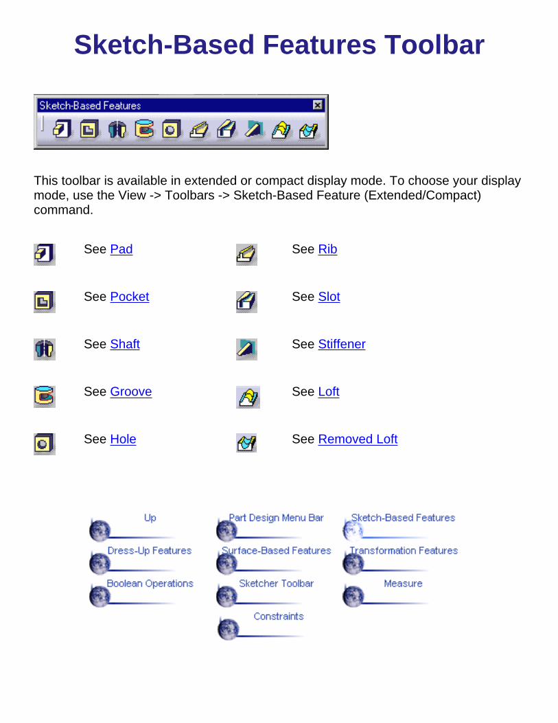
Sketch-Based Features Toolbar
This toolbar is available in extended or compact display mode. To choose your displaymode, use the View -> Toolbars -> Sketch-Based Feature (Extended/Compact)command.
See Pad See Rib
See Pocket See Slot
See Shaft See Stiffener
See Groove See Loft
See Hole See Removed Loft

Dress-Up Features Toolbar
See Edge Fillet See Chamfer
See Variable Radius Fillet See Basic Draft and Draft with PartingElement
See Face-Face Fillet See Shell
See Tritangent Fillet See Thickness
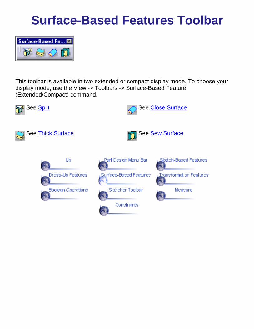
Surface-Based Features Toolbar
This toolbar is available in two extended or compact display mode. To choose yourdisplay mode, use the View -> Toolbars -> Surface-Based Feature(Extended/Compact) command.
See Split See Close Surface
See Thick Surface See Sew Surface

Transformation Features Toolbar
See Translation See Rectangular Pattern
See Rotation See Circular Pattern
See Symmetry See User Pattern
See Mirror See Scaling

Boolean Operations Toolbar
This toolbar is optional. You can access it using the View -> Toolbars -> BooleanOperations command.
See AssemblingBodies
See Intersecting Bodies
See AddingBodies See Trimming Bodies
See Removing Bodies See Keeping and Removing Faces

Sketcher Toolbar
See CATIA Version 5 Release 3 Sketcher User'S Guide

Measure Toolbar
See Measuring Minimum Distances& Angles between GeometricalEntities or Points
See Measuring Elements

Constraints Toolbar
See Setting Constraints in the 3D Area
See Setting Constraints in the 3D Area

CustomizingThis section describes the different types of setting customization you can perform. Alltasks described here deal with permanent setting customization. These tasks are:
ConstraintsTree ViewGeneral SettingsMeasurement Display

Glossary
Bbody See part body.
Cchamfer A cut through the thickness of the feature at an angle, giving a sloping
edge.child A status defining the genealogical relationship between a feature or
element and another feature or element. For instance, a pad is the child ofa sketch. See also parent.
constraint A geometric or dimension relation between two elements.
Ddraft angle A feature provided with a face with an angle and a pulling direction.
Ffeature A component of a part. For instance, shafts, fillets and drafts are features.fillet A curved surface of a constant or variable radius that is tangent to, and
that joinstwo surfaces. Together, these three surfaces form either an inside corneror anoutside corner.
Ggroove A feature corresponding to a cut in the shape of a revolved feature.
Hhole A feature corresponding to an opening through a feature. Holes can be
simple, tapered, counterbored, countersunk, or counterdrilled.
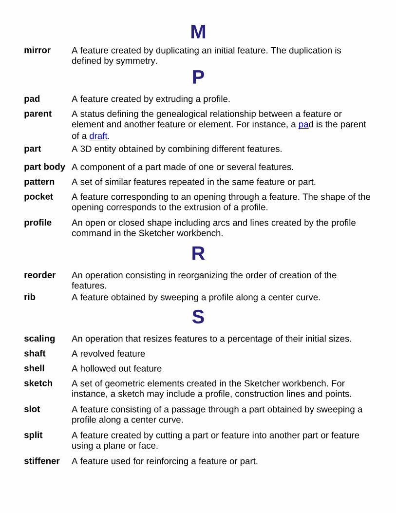
Mmirror A feature created by duplicating an initial feature. The duplication is
defined by symmetry.
Ppad A feature created by extruding a profile.parent A status defining the genealogical relationship between a feature or
element and another feature or element. For instance, a pad is the parentof a draft.
part A 3D entity obtained by combining different features.
part body A component of a part made of one or several features.pattern A set of similar features repeated in the same feature or part.pocket A feature corresponding to an opening through a feature. The shape of the
opening corresponds to the extrusion of a profile.profile An open or closed shape including arcs and lines created by the profile
command in the Sketcher workbench.
Rreorder An operation consisting in reorganizing the order of creation of the
features.rib A feature obtained by sweeping a profile along a center curve.
Sscaling An operation that resizes features to a percentage of their initial sizes.shaft A revolved featureshell A hollowed out featuresketch A set of geometric elements created in the Sketcher workbench. For
instance, a sketch may include a profile, construction lines and points.slot A feature consisting of a passage through a part obtained by sweeping a
profile along a center curve.split A feature created by cutting a part or feature into another part or feature
using a plane or face.stiffener A feature used for reinforcing a feature or part.