PART C ENGINEERING DESIGN - Amazon Web Services C ENGINEERING DESIGN 68 10.3 SIGHT DISTANCE The...
64
67 10. ROAD DESIGN 10.1 INTRODUCTION This section sets out the standard design criteria for road works. It is not intended to prohibit any alternative arrangements or approaches. Innovative or non-standard designs may be considered, but not necessarily accepted. Sufficient data and principles of design for any innovative or non-standard design shall be submitted for consideration. Aspects not specifically referred to in this Manual should be generally in accordance with the following documents: > AustRoads: Guide to Road Design, incorporating AGRD01 to AGRD07 and all sub-sections. > Standard Drawings appended. 10.2 DESIGN CRITERIA 10.2.1 Operating Speed The desired maximum operating speed, on which the geometric design of each road type is based, shall be:- Table 2: Operating Speeds ZONE ROAD TYPE MAXIMUM OPERATING SPEED Residential Access Lane, Place and Street 50 km/h Connector Road Level 1 & 2 50 km/h Trunk Connector 60 km/h Commercial & Industrial Access 50 km/h All Arterial Road Authority Specifies * Note that the design speed is not necessarily the posted or operating speed. 10.2.2 Design Vehicle The design vehicle(s) to be adopted shall be selected in accordance with the current version of the “Austroads Design Vehicles and Turning Path Templates”. Turning radii and vehicle speeds used in road design shall be confirmed with Council at the commencement of design development. PART C ENGINEERING DESIGN
Transcript of PART C ENGINEERING DESIGN - Amazon Web Services C ENGINEERING DESIGN 68 10.3 SIGHT DISTANCE The...

67
10. ROAD DESIGN10.1 INTRODUCTION
This section sets out the standard design criteria for road works. It is not intended to prohibit any alternative arrangements or approaches. Innovative or non-standard designs may be considered, but not necessarily accepted. Sufficient data and principles of design for any innovative or non-standard design shall be submitted for consideration.
Aspects not specifically referred to in this Manual should be generally in accordance with the following documents:
> AustRoads: Guide to Road Design, incorporating AGRD01 to AGRD07 and all sub-sections.
> Standard Drawings appended.
10.2 DESIGN CRITERIA
10.2.1 Operating Speed
The desired maximum operating speed, on which the geometric design of each road type is based, shall be:-
Table 2: Operating Speeds
ZONE ROAD TYPE MAXIMUM OPERATING SPEED
Residential Access Lane, Place and Street 50 km/h
Connector Road Level 1 & 2 50 km/h
Trunk Connector 60 km/h
Commercial & Industrial
Access 50 km/h
All Arterial Road Authority Specifies
* Note that the design speed is not necessarily the posted or operating speed.
10.2.2 Design Vehicle
The design vehicle(s) to be adopted shall be selected in accordance with the current version of the “Austroads Design Vehicles and Turning Path Templates”. Turning radii and vehicle speeds used in road design shall be confirmed with Council at the commencement of design development.
PART C ENGINEERING DESIGN

68
10.3 SIGHT DISTANCE
The requirements for sight distance on all roads and intersections shall be in accordance with the current AustRoads Guide.
10.4 HORIZONTAL ALIGNMENT
10.4.1 General
Horizontal alignment of all roads shall be designed in accordance with the requirements of AustRoads Urban Road Design Manual.
10.4.2 Superelevated
Where curves are superelevated, it is necessary to ensure that any low points in the kerb and channel resulting from the application of superelevation are adequately drained.
69
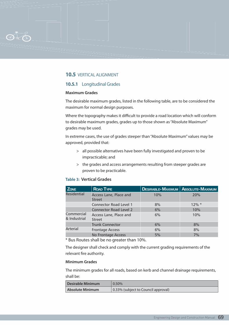
10.5 VERTICAL ALIGNMENT
10.5.1 Longitudinal Grades
Maximum Grades
The desirable maximum grades, listed in the following table, are to be considered the maximum for normal design purposes.
Where the topography makes it difficult to provide a road location which will conform to desirable maximum grades, grades up to those shown as “Absolute Maximum” grades may be used.
In extreme cases, the use of grades steeper than “Absolute Maximum” values may be approved, provided that:
> all possible alternatives have been fully investigated and proven to be impracticable; and
> the grades and access arrangements resulting from steeper grades are proven to be practicable.
Table 3: Vertical Grades
ZONE ROAD TYPE DESIRABLE-MAXIMUM ABSOLUTE-MAXIMUMResidential Access Lane, Place and
Street10% 20%
Connector Road Level 1 8% 12% *Connector Road Level 2 6% 10%
Commercial & Industrial
Access Lane, Place and Street
6% 10%
Trunk Connector 6% 8%Arterial Frontage Access 6% 8%
No Frontage Access 5% 7%* Bus Routes shall be no greater than 10%.
The designer shall check and comply with the current grading requirements of the relevant fire authority.
Minimum Grades
The minimum grades for all roads, based on kerb and channel drainage requirements, shall be:
Desirable Minimum 0.50%
Absolute Minimum 0.33% (subject to Council approval)

70
10.5.2 Vertical Curves
General
A vertical curve, of parabolic form, shall be provided at every change of grade where the arithmetic change of grade is more than:
Access, Collector and Trunk Collector 1.0%
Arterial roads 0.6% (with an operating speed of 80kph or greater)
Every effort should be made to provide lengthy vertical curves for improved appearance.
Generally, the minimum length of a vertical curve shall be 15m.
All vertical curves shall be designed in accordance with AustRoads Standards.

71
10.6 STANDARD CROSS-SECTION
The standard cross section for various roads in new subdivisions shall be in accordance with the relevant PSP for the area. Basis for the standard cross sections is outlined in the PSP Guidelines and associated Road note/s.
10.6.1 Cross-Section Elements
Standard Cross Section elements shall be as follows:-
Table 4: Road Elements
ACCESS
LANE
ACCESS
PLACE
ACCESS
STREET 1ACCESS
STREET 2CONNECTOR
STREET
TRUNK
CONNECTOR
(2 LANE)ARTERIAL
Traffic Volume (vpd)
300 300-1000 1000-2000 2000-3000
3000-7000 7000-12000
12000-60000
Target Operating Speed (kph)
10 15 30 40 50 60 60-80
Carriageway Width (m)1
6.0 5.52 7.3 6.0 7.0 3.5 lane each way
2*10.57
Parking Within Street
None Unmarked Unmarked 2.3 marked lanes both sides
2.3 marked lanes both sides
2.3 marked lanes
None
Verge Width (m) 3
Only if required for servicing
4.50 / 4.209
4.50 / 4.209
4.7 min each side
5.0 min each side
5.25 min each side
5.0 min
Kerbing5 Subject to pavement cross fall
B2, SM210 B2, SM210 B2, SM210 B2, SM210 B2, SM210 B2, SM210
Footpath Provision8
None 2 * 1.54 2*1.5 2*1.5 2*1.5 2*1.5 2*1.5 min, opportunity for shared paths
Cycle Path/Lane Provision8
None None None6 Optional 2*1.7 2*1.7 2.0 both sides, opportunity for shared paths

72
1. Carriageway Width is line of kerb to line of kerb.
2. 7.3m if parking both sides.
3. Verge Width include nature strip and footpath (where required).
4. For <300vpd, may be reduced to 1 subject to Council approval.
5. B2 and SM2 for standard cross fall, refer to Standard Drawings.
6. Carriageway designed as a shared zone and appropriately signed.
7. 6 lane arterial; if 4 lane arterial is adopted reduce to 2*7.0.
8. Refer Table 5 when shared path required.
9. Verge width is different for each side to accommodate services.
10. SM2 kerb and channel may be used subject to Council approval.
11. Refer to the relevant PSP for individual road reserve widths.
Table 5: Additional Road Elements
ELEMENT CRITERIA DIMENSION ELEMENT CRITERIA DIMENSION
Travel Lane absolute min. 3.0m Shoulders1 Access Road 1.20m
standard 3.5m Collector Road 1.20mone-way 4.0m Arterial Road 2.00m
Parking Lane minor road 2.3m Carriageway Service Road 5.5 m
major road 2.6m Nature strip minimum for street trees 3.5 m
Connector Street Indented parking lane
2.32 m Footpath Standard 1.5 m
Turn Lane minimum 3.0m Footpath
offset(from property line) 0.05 m
standard 3.5m Services spacing Standard
As per standard drawings
Bicycle lanes (on road)
Desirable lane width
1.5m on Access Street, otherwise 1.7m
Median absolute min. 1.2m (paved)
Shared path minimum 2.5m desirable min. 2.5m (paved)
Incorporating turn lane 5.2m
Minimum (for minor street tree planting)
3.0m (grassed)
1. Permanent, rural or interim urban
2. 2.1m is acceptable in low volume collector streets with an on road bicycle lane.

73
10.7 CROSS FALL
10.7.1 Normal Cross Section
On straight lengths of two-way road the pavement cross section will normally be graded with the high point (crown) on the pavement centreline, with a fall to each channel.
However, on steep side slopes, the crown may be offset, towards the higher side of the road to obtain better conformity of road levels with the natural side slope.
On divided roads each pavement will normally be graded to fall from the median to the outer channel.
10.7.2 Normal Cross fall
The normal cross fall of pavement and shoulders on straight alignment shall be:-
Bituminous Sealed pavements 3.33% (1 in 30)
Bituminous Sealed Shoulders 3.33% (1 in 30)
Unsealed Shoulders 5.00% (1 in 20)
10.7.3 Maximum and Minimum Cross fall
Where steeper or flatter cross falls than the normal are required, for example at the approach to intersections, or turning circles of cul-de-sacs, the maximum and minimum permissible pavement cross falls shall be:-
Maximum Cross fall 6.67% (1 in 15)
Minimum Cross fall 2.50% (1 in 40)
Intersections should be designed to avoid ponding and be free draining.

74
10.8 KERB AND CHANNEL
10.8.1 Location
Concrete kerb and channel shall be provided on both sides of all urban residential and commercial roads.
10.8.2 Kerb and Channel Types
The standard kerb and channel profile shall be as shown on the Standard Drawings. In general SM2 or B2 profiles are to be used in residential developments
Exceptions to the use of these profiles may be considered in the following instances:-
> Kerb only may be used with one-way cross fall pavements and reverse fall nature strip on high side;
> Medians & Traffic Islands, where semi-mountable is shown, shall be M2, M3, SM2 or SM3;
> Roundabout outer kerbs shall be SM2 from TP to TP. Roundabout splitter islands are to be SM3. Roundabout central island outer kerb shall be SM3;
> For small islands (with an enclosed surface area not greater than 3m2) SM1 may be used;
> Barrier kerb shall be used where the kerb abuts a Council reserve.

75
10.8.3 Grading
General minimum kerb and channel grade shall be 0.5% (1 in 200); in exceptional circumstances a 0.3% grade may be used subject to Council approval.
Vertical curves should be as long a length as possible. Generally a minimum length of 15m shall be used.
Where the change in grade in a vertical curve will result in excessively long flat areas, the invert grade shall be extended through to the low point to provide a minimum 0.3% grade.
Designers shall limit crest curves that have minimum grade (0.3% to 0.5%) to between 30m and 50m length.
In kerb returns the desirable minimum grade is 0.75% and absolute minimum is 0.50%.
10.8.4 Kerb Radii
Kerb radii shall allow for the nominated design vehicle to move through the swept path without impedance. Swept paths may cross over the road centreline in access lanes, places and streets.
The radius of the kerb and channel, measured to back of kerb, at an intersection shall be selected in accordance with “Austroads Guide to Road Design Part 3 – Geometric Design” and current versions of the “Austroads Design Vehicles and Turning Path Templates”.
Use of the Austroads template for a “Standard Service Vehicle” (8.8m) is recommended where access for domestic waste collection services is the governing criteria.
The following kerb radii are considered to be desirable minimums:
Access Street or Place to any Street 8.0m*
Connector or Trunk Connector Street to Trunk Connector or Arterial 12.50m*
Arterial to Arterial 15.00m*
* Smaller radii may be considered by Council for special circumstances subject to demonstration that vehicle swept paths are acceptable. Swept paths shall be clear of on street parking spaces.

76
10.9 FOOTPATHS & NATURE STRIPS
10.9.1 Cross-section
The cross-section of footpaths and nature strips shall conform to those shown on Standard Drawings.
In high activity areas, such as schools and shops, the street verge is usually fully paved between title boundary and kerb. In these areas consideration should be given to the provision of a separation treatment between pedestrians and the adjoining roadway to improve safety.
In areas with no footpath, the nature strip shall be graded to accommodate the future addition of a footpath. In these areas, driveways shall be constructed to levels to accommodate the future footpath.
10.9.2 Cross fall
Where concrete footpath paving is to be provided within a street reserve, the footpath cross fall shall be 2.0% towards the road. In all other instances concrete footpaths and shared paths shall have a maximum cross fall of 2.5%.
Nature strip cross falls shall be within the range of 2.5% and 10.0%, towards the road (refer to other sections in this manual for exceptions).
Standard cross falls shall not be exceeded at any location where vehicular access to allotments may be required.

77
10.9.3 Provision of Tactile Ground Surface Indicators
Use of Tactile Ground Surface Indicators (TGSI) shall be in accordance with DDA requirements and any Council strategies for disabled access. The use of TGSI will be minimised by designing for a continuous path of travel in order to avoid their need at minor access street intersections. Changes of footpath direction at crossings are therefore discouraged.
Footpath and Pram Crossings (kerb ramps) in new subdivisions shall be provided in accordance with DDA requirements. Location and alignment shall support the principle of “continuous path of travel” requirements.
TGSI are not required where:
> The geometry of a kerb ramp at an intersection is fully compliant with AS1428.1; and
> The ramp is located on the direct extension of the property line; and
> The top of the ramp is no more than 3000mm from the intersection of property lines.
TGSI are required at all kerb ramps that do not comply with the above, at all mid block crossings, and at high usage vehicle crossovers, e.g. service stations and shopping centre car parks.
Directional TGSI are to be used where a kerb ramp is not located on the direct extension of the property line in an accessible path of travel from the building / boundary line and will lead to warning indicators installed at the crossing (kerb ramp) point.
Directional and warning TGSI will always be required at mid block pedestrian or school crossings, tram and bus stops.
Refer Standard Drawings or particular requirements of the Precinct Structure Plan.

78
10.10 ACCESS TO FRONTAGE ALLOTMENTS
10.10.1 General
Steep side slopes on the natural surface can result in difficulty in vehicular access to allotments fronting the road.
10.10.2 Driveway Grades
The desirable maximum driveway grade is 25% (1 in 4) for a residential allotment. In steep terrain, driveway cut or fill earthworks into the allotments are to be shown on the plans so that the driveway access is created with the subdivision works.
Driveways approaching maximum grades shall be checked for clearance using an 85th percentile standard car.
10.10.3 Maximum Nature Strip Slope
The maximum acceptable nature strip slope, based on grading driveways to the natural surface at 6.0m from the alignment (i.e. at the property boundary or, where there is a footpath, the pavement side of the footpath), for various standard road cross-sections, is:-
Residential Access Lane, Place or Street 12%
Residential Connector 11%
10.11 TREATMENTS TO MINIMISE DRIVEWAY EXCAVATION
Excavation of Driveways and garage sites, on lots on the high side of the road, may be considered where only a small number of lots (e.g. 4 or 5) are affected, such as in a short cutting or at the end of a cul-de-sac.
10.11.1 Offsetting of the Crown and one-way cross fall
In circumstances where the natural cross slope of the existing terrain will lead to unreasonably high cut batters, offsetting the crown or one-way cross fall may be considered.
Offsetting of the crown, on a two-way road, is permissible, provided that sufficient stormwater capacity is retained in the channel and roadway on the high side of the road. Required capacity will depend on catchment, and on the spacing of storm water entry pits. Offset crown widths shall be sufficient to ensure that the crown is able to be laid with asphalt machinery.
A pavement with one-way cross fall may be approved only where drainage requirements can be adequately met.

79
10.11.2 Reverse Cross fall – Divided Roads
In extreme cases, reverse cross fall, on the uphill lane of divided roads, is permissible provided that adequate drainage capacity is provided in the uphill median channel, and precautions taken to intercept flow at median openings.
10.11.3 Median Cross fall
Median Cross fall, on divided roads, should desirably not exceed a maximum of 16%, with 33% as an absolute maximum, unless a retaining wall is provided and there are no proposed median breaks in the median.
At median openings however, the pavement cross fall shall not exceed 5%.
10.11.4 Modification of the Footpath Cross fall
Modification of the footpath fall will only be considered in extreme circumstance; as this approach may increase the catchment area discharging stormwater into the downhill lots, it shall be avoided where possible.
Reverse fall (away from kerb) nature strips with footpath ‘spoon drain’ will only be considered in extreme circumstances as this approach requires higher maintenance for drainage without significant access benefits.
10.11.5 A Split-Level Road
Modification of the road section to accommodate a split level road will only be considered in extreme circumstance.

80
10.12 VEHICULAR CROSSINGS
Vehicle crossings shall be constructed during road construction unless otherwise required as a condition of the Planning Permit. Residential crossings are to be in accordance with the Standard Drawings.
10.13 UTILITY ALLOCATIONS
The location of utility services is to be in accordance with the requirements of the relevant Council and Service Authority.
For clarity, typical cross sections showing service allocations are indicated in Appendix D.
Utility services are an important component of infrastructure provided for our newest suburbs.
Standard placement of utility services within road reserves ensures appropriate clearances and access, while minimising conflicts between other road reserve infrastructure.
Consideration must be given to minimising road reserve widths in order to assist with the cost of providing new developments while ensuring housing affordability.
Layouts and road cross sections may need to be reviewed if non-standard trunk utilities are to be provided because these utilities are typically larger infrastructure requiring larger clearances.
10.14 ROUNDABOUTS
Roundabouts shall be designed according to AustRoads Guide to Road Design Part 4B: Roundabouts. (AGRD04B/09).
10.15 INTERSECTION THRESHOLD TREATMENTS
Where required by the PSP or Planning Permit, threshold treatments shall be provided on the minor road of an intersection; the materials and surfaces of the threshold
treatment are subject to Council approval.

81
11. PAVEMENT DESIGN11.1 SCOPE
The scope of this Section covers the design of pavements for residential subdivisions. A variety of pavement types, including flexible granular pavements, deep lift asphalt pavements and rigid concrete pavements are considered.
For asphalt pavement design, requirements are restricted to the design and construction of road pavements in new urban streets surfaced with not less than two layers of asphalt and flanked by kerb and channel.
A minimum of two layers of asphalt has been adopted as the standard, including an option of deferring the placement of the final wearing course. This approach has the following advantages:
> Ability to defer placement of the final wearing course if circumstance indicate that this can be undertaken at another more suitable time due to construction, weather or other factors relating to completion of other subdivision works;
> Eliminating damage to the wearing course during final stages of the work;
> Underlying pavements are able to be covered with a base course of asphalt at a much earlier stage and often without weather restrictions that a wearing course requires; and
> Can reduce the costs of development due to the ability to complete works and secure release at an earlier time.

82
11.2 DESIGN REFERENCES
The design of the pavements shall be carried out by qualified engineering consultants in accordance with this Manual and the principles, practices and procedures detailed in the following design references:
> VicRoads (July 2010). Code of Practice RC 500.22 : Code of Practice for Selection & Design of Pavements & Surfacings. (RC 500.22);
> VicRoads (October 2004). Code of Practice RC 500.20 : Assignment of CBR (Strength) and Percent Swell to Earthworks and Pavement Materials. (RC 500.20)
> VicRoads (Current). Standard Specifications for Roadworks & Bridgeworks. (VicRoads Standard Specifications)
> Austroads (May 2008). Guide To Pavement Technology - Part 2 : Pavement Structural Design. Publication No. AGPT02/08. (AGPT02).

83
11.3 QUALIFIED CONSULTANTS
Pavement design and associated geotechnical field and laboratory investigation testing shall be undertaken by qualified consultants who have relevant experience in the required field of practice. To ensure that this requirement is met, only those consultants who are currently registered on the VicRoads “Register of Pre-Qualified Contractors & Consultants” are eligible to provide services within the categories outlined in Table 6 below.
Table 6: Minimum VicRoads Pre-Qualification Levels
DESCRIPTION OF SERVICE VICROADS PREQUALIFICATION LEVEL
Category Service Level Description
Pavement Pavement Types E1-E4, N1-N4
ND1 Basic Pavement Design
Design Pavement types E5-E6, N5-N6
ND2 Intermediate Pavement Design
Rigid Pavements ND3 Advanced Pavement Design
Geotechnical At Grade Subgrade Investigation
PT2 Field Investigation & Laboratory Testing
Investigation Road Alignment Investigation
AB1 Alignment & Bridge Investigation (Minor)
Ground Contamination GEV Geo-Environmental Investigation

84
11.4 PAVEMENT DESIGN PARAMETERS
11.4.1 General
The general aim of pavement design is to select the most economical pavement thickness and composition which will provide a satisfactory level of service over the adopted design life taking into account the prevailing subgrade conditions, the characteristics of the materials in the pavement and the anticipated level of traffic.
The pavement design process accordingly requires that a number of input variables be selected and assigned to any particular design. These design parameters are listed below, together with their associated reference in this guide :
> Project Reliability Level (Section 11.4.2) – Assignment of a Project Reliability Level for mechanistic pavement design
purposes and for design of rigid pavements.
> Subgrade (Section 11.5) – Assignment of subgrade strength, its associated classification as expansive
or otherwise, capping layer fills, and subgrade improvement measures where required.
> Pavement Materials (Section 11.6) – Selection and specification of appropriate pavement materials, their
properties, and assignment of associated characteristics to be used in the design process.
> Design Traffic (Section 11.7) – Assessment of forecast future traffic for the required design period,
including future growth, the proportion of heavy vehicles and their associated loading characteristics.

85
11.4.2 Project Reliability Levels
The Project Reliability for a particular project is defined as the probability that the pavement, when constructed in accordance with the chosen design, will outlast its design traffic before major rehabilitation is required.
The Project Reliability Level shall be selected by the designer in accordance with Table 7 below for each category of road as appropriate. A designer may choose to select a higher Project Reliability Level if the circumstances for any particular project are warranted.
Table 7: Project Reliability Levels
ROAD TYPE PROJECT RELIABILITY
Access Lane 90 %
Access Place 90 %
Access Street 90 %
Connector Street 90 %
Arterial Road 95 %
The granular pavement design chart in Appendix B, applicable for unbound granular pavements surfaced with two layers of asphalt, has been prepared for a Project Reliability Level of 90%.

86
11.5 SUBGRADE & EARTHWORKS
11.5.1 Subgrade Evaluation
Subgrade investigation testing, including both field and laboratory testing and associated evaluation and determination of subgrade strength, shall be undertaken in accordance with all relevant Australian Standards and relevant requirements of the following references:
> VicRoads Manual of Codes of Practice, test methods and design guides;
> Standards Australia test methods; and
> Austroads Design Guides.
The scope, extent and location of investigation testing should be commensurate with the location and magnitude of the proposed works. Notwithstanding the requirements outlined in the above guides, the following minimum testing shall be undertaken for each project for the purpose of characterising the nature and condition of the subgrade:
> excavation of test bores or pits to a depth of at least 1.0 m or more than 0.5m below the proposed subgrade (whichever is the greater), at intervals not exceeding 120 m, with a minimum of 3 test sites on any one project;
> dynamic cone penetrometer testing and measurement of field moisture content at each test site;
> grading and Atterberg limit testing on at least 2 representative samples of subgrade material; and
> laboratory soaked (4 day) CBR tests on at least 2 representative laboratory remoulded samples of subgrade material.
If rock is encountered during the field investigation, the requirement to excavate bores or pits to a depth of 1.0 m may be waived.

87
11.5.2 Maximum Subgrade Design CBR
To ensure that uniform minimum pavement design standards are met, the subgrade design CBR assigned for pavement design purposes shall not exceed 10%.
11.5.3 Expansive Subgrades
Subgrade Classification
Subgrade materials with an assigned swell ≥ 2.5% as determined in accordance with RC 500.20 shall be classified as expansive for the purpose of this guide. These materials are categorised by AGPT02 to be at the very least highly expansive.
Treatment of Expansive Subgrades
Since expansive subgrades exhibit seasonal volume changes with resulting shape loss and environmentally induced cracking, appropriate measures shall be incorporated into the design of the pavement as outlined in RC 500.22 Section 5.2 and AGPT02 Section 5.3.5.
These shall include, without being limited to, incorporation of the following features into the design in accordance with the referenced sections of this guide :
> minimum total pavement thickness as specified herein;
> provision of a capping layer as specified herein; and
> attention to the placement of subsurface drainage as specified herein.
In addition to the measures outlined above, any associated landscaping design will need to take into account current VicRoads practice.

88
11.5.4 Weak Subgrade
In addition to the pavement composition requirements outlined in this guide, an appropriate working platform, or subgrade improvement layer, may need to be incorporated into the pavement structure at the time of construction to facilitate placement and compaction of subsequent pavement layers. The subgrade improvement layer may be incorporated into the pavement design in accordance with the following guidelines :
> subgrade design CBR of 2% or greater - the thickness of the working platform may be included within the required overall pavement thickness provided that the materials satisfy the requirements of this guide;
> subgrade design CBR < 2% - the pavement thickness design may be based upon a subgrade design CBR of 2%, provided that the subgrade is first improved to a depth of not less than 150 mm and that the subgrade improvement layer is not incorporated into the overall pavement thickness.
Where subgrade improvement layers are incorporated into the pavement structure, the usual requirements for compaction shall apply. In the case of test rolling however, only the uppermost improvement layer shall be required to be test rolled so as to withstand visible deformation and springing. The requirement to test roll any underlying improvement layers, and subgrade, may be waived.
Subgrade improvement is most often required because of the presence of unsuitable materials or the presence of high moisture contents at the time of construction. In determining the need for subgrade improvement, it is important to take into account the potential for the subgrade to be weakened if drainage of the formation is inadequate during construction.
Any isolated small areas of subgrade which are weaker than the subgrade CBR assigned for design of the pavement, or which are weak at the time of construction, shall be treated by excavation to a sound base and backfilled to subgrade level with either of the following materials :
> suitable surplus earthworks materials from the site; or
> imported Type A capping layer material.

89
11.5.5 Type A Materials
Capping Layer
To ensure that long term environmental effects are minimised, a capping layer shall be placed immediately above subgrades classified as being expansive. The capping layer shall comprise lower subbase quality material, or in-situ stabilised material, or imported Type A capping layer material, with the following additional properties :
> assigned swell ≤ 1.5%; and
> permeability ≤ 1 x 10⁻⁹ m/sec.
In addition to the material properties outlined above, the capping layer shall have the following minimum physical characteristics:
> thickness ≥ 150 mm, or 2.5 times the maximum particle size of the capping layer material, whichever is the greater; and
> extend for a distance ≥ 1.0 m behind the back of kerb and channel, or the edge of the pavement if there is no kerb and channel, except for arterial roads where the distance shall be ≥ 1.5 m.
The capping layer may be included in the total thickness of unbound granular pavements if the laboratory soaked CBR of the material complies with the requirements for lower subbase materials, or the following requirements.
Selected Material
All Type A selected material shall have an assigned swell ≤ 1.5%.
Unbound Granular Pavements
Where unbound granular pavements are designed for a subgrade design CBR of 2% and the total pavement thickness ≥ 440 mm, as much as the lower 150 mm of the pavement may comprise the following materials in lieu of lower subbase materials, provided that the material has a laboratory soaked CBR ≥ 8%:
> imported Type A capping layer material; or
> imported Type A selected material; or
> in-situ stabilised subgrade materials.

90
11.6 PAVEMENT MATERIALS
11.6.1 General
Pavement materials shall be designed to be supplied, placed and compacted in accordance with the version of the VicRoads Standard Specifications current at the time of commencing the pavement design. The principal requirements relating to the following materials selected for pavements designed in accordance with this guide are outlined in the sections below.
11.6.2 Asphalt
Wearing Course Asphalt
Designers are required to pay particular attention to the selection of wearing course asphalt at roundabouts and at signalised intersections on Connector Streets and Arterial Roads where the computed HVs/lane > 500 hvpd in accordance with RC 500.22 Appendix D.
Bitumen Crumb Rubber Asphalt
Bitumen crumb rubber asphalt is a special standard VicRoads mix incorporating a bitumen crumb rubber binder, requiring higher ambient temperatures for placing than conventional asphalt. Asphalt containing crumb rubber binder shall not be placed when the majority of the area to be paved has a surface temperature < 15°C. Bitumen crumb rubber asphalt is mandatory for all Base Course in pavements on expansive subgrades (refer to Table 11).
Bituminous Prime
In the case of all unbound granular pavements, a prime, or alternatively a primerseal, shall be selected and designed by the contractor and applied to the top of the base course crushed rock. Its role is to bind the subsequent asphalt base course to the crushed rock base and to waterproof the pavement.
Where a primerseal is selected, it shall comprise:
> Size 5 or Size 7 bitumen emulsion primerseal (not exceeding 60% bitumen content)
> Application of residual binder of > 0.9 l/m2.
91
11.6.3 Unbound Granular Pavements
Minimum requirements for materials to be selected for use in unbound granular pavements are :
> Base – 20 mm Class 2 crushed rock, or – 20 mm Class CC2 crushed concrete.
> Upper Subbase – 20 mm Class 3 crushed rock, or better, or – 20 mm Class CC3 crushed concrete, or better, or – 40 mm Class 3 crushed rock (for layer thickness in the range of 150-200
mm on non expansive subgrades).
> Lower Subbase – Class 4 crushed rock or better, or – Class CC4 crushed concrete or better, or – subbase quality gravel, sand or soft and rippable rock with previous
proven performance and a laboratory soaked CBR ≥ 15%, or – imported or in-situ lime, cement, bitumen or mechanically stabilised
materials or a combination of these with a laboratory soaked CBR ≥ 15%.
11.6.4 Asphalt Pavements
Minimum requirements for materials to be selected for use as subbase in asphalt pavements, comprising either deep strength asphalt or full depth asphalt, are outlined in RC 500.22 Sections 7.2.2, 11.2 and 11.4.

92
11.7 DESIGN TRAFFIC
11.7.1 Design Period
Calculation of Design Traffic shall be based upon a minimum design period of 20 years. A designer may choose to select a longer design period if the circumstances for any particular project are warranted.
11.7.2 Calculation of Design Traffic
Calculation of Design Traffic shall be undertaken in accordance with RC 500.22 and AGPT02 to suit the characteristics and requirements of each particular project. In addition to the design period outlined above, the calculations will require an appropriate assessment of the following input data :
> forecast total traffic over the duration of the design period, including any necessary provision for future traffic growth;
> the proportion of heavy vehicles, including waste management vehicles, and an allowance for buses where the street will form part of a bus route;
> heavy vehicle traffic generated by construction during development of subdivisions in the case of Access Lanes, Access Places and Access Streets;
> vehicular trafficking patterns including the directional split, vehicle wander on wide pavements and lane distribution on multi-lane roads; and
> heavy vehicle load factors, incorporating the average number of HVAG per HV, and the average number of ESA per HVAG in the case of flexible pavements.
Typical Design Traffic parameters for residential subdivisions are outlined in Appendix B and are provided as a guide only. The data shall not be used as a substitute for the designer making an assessment of relevant parameters for each particular project, particularly in the case of industrial subdivisions where detailed heavy vehicle traffic forecasts are necessary.
Where the width of a street, or the presence of parked vehicles, results in two way traffic either partially or fully using the same travel path, consideration needs to be given to assignment of the appropriate Direction Factor, required to be within the range of 0.5 to 1.0.

93
11.7.3 Minimum Permissible Standards
To ensure that minimum pavement design standards are met, values of Design Traffic parameters, and the resultant computed Design Traffic, shall not be less than the lower range outlined in Appendix B for each respective road type.
To take into account the heavy vehicle traffic generated by construction during development of subdivisions, the Design Traffic computed for design of flexible pavements, DESA, shall be increased by not less than the values outlined in Table 8 below.
Table 8: Minimum Increase In DESA
ROAD TYPE DESA INCREASE
Access Lane 5 %
Access Place 4 %
Access Street 3 %

94
11.8 FLEXIBLE PAVEMENT DESIGN
11.8.1 Non-Expansive Subgrades
Unbound Granular Pavements
Where subgrades are defined as non-expansive, the use, thickness and composition of unbound granular pavements shall satisfy the following criteria :
> only permissible where DESA ≤ 1.0 x 10⁶ ESAs
> two layers of asphalt surfacing to allow staged construction of new subdivisions, and
> the design chart in Appendix B, subject to the minimum requirements outlined in Table 9 below.

95
Table 9: Unbound Granular Pavements on Non-Expansive Subgrades
ROAD TYPEACCESS LANE
ACCESS PLACE
ACCESS STREET 1
ACCESS STREET 2
PavementType
N1 N2 N3 N4
Max Permissible DESA (ESA)
5.0 x 10⁴ 1.0 x 10⁵ 5.0 x 10⁵ 1.0 x 10⁶
Wearing Course
Size 7 Type L Asphalt (Class 170 binder)
20 mm -- -- --
Size 10 Type L Asphalt (Class 170 binder)
-- 30 mm -- --
Size 10 Type N Asphalt (Class 170
binder)-- -- 30 mm --
Size 14 Type N Asphalt
-- -- -- 40 mm
Base Course
Size 10 Type N Asphalt (Class 170
binder)30 mm 30 mm 30 mm --
Size 14 Type HP Asphalt (Class A10E
binder)-- -- -- 40 mm
Bituminous Prime Prime or primerseal yes yes yes Yes
Base Base Material refer Section 11.6.3
140 mm 130 mm 130 mm 110 mm
Upper Subbase
Upper Subbase Material refer Section
11.6.3-- -- (varies) (varies)
Lower Subbase
Lower Subbase Material refer Section
11.6.3(varies) (varies) (varies) (varies)

96
Asphalt Pavements
Where subgrades are defined as non-expansive, the use, thickness and composition of asphalt pavements, comprising either deep strength asphalt or full depth asphalt as defined by RC 500.22, shall satisfy the following criteria :
> mandatory where DESA > 1.0 x 10⁶ ESA; and
> Section 11 and Appendix D of RC 500.22, subject to the minimum requirements outlined in Table 10 below.
Table 10: Asphalt Pavements on Non-Expansive Subgrades
ROADTYPECONNECTORSSTREET
ARTERIALROAD
Pavement Type N5 N6
Max Permissible DESA (ESA) 3.0 x 10⁶ No Limit
Wearing Course Size 14 Type N Asphalt 40 mm --
Size 14 Type H Asphalt (or better) -- 40 mm
Intermediate Course
Size 20 Type SI Asphalt (or type SS) (varies) (varies)
Base Course Size 20 Type SI Asphalt (or type SF) 75 mm 75 mm
SubBase (Cementitious and/or unbound materials) (varies) (varies)

97
11.8.2 Expansive Subgrades
Unbound Granular Pavements
Where subgrades are defined as expansive, the use, thickness and composition of unbound granular pavements shall satisfy the following criteria :
> only permissible where DESA ≤ 1.0 x 10⁶ ESAs;
> two layers of asphalt surfacing to allow staged construction of new subdivisions;
> the design chart in Appendix B, subject to the minimum requirements outlined in Table 11 below; and
> minimum total thickness defined by the expansive subgrade curve in Appendix B.
Table 11: Unbound Granular Pavements On Expansive Subgrades
ROAD TYPEACCESS LANE
ACCESS PLACE
ACCESS STREET 1
ACCESS STREET 2
Pavement Type E1 E2 E3 E4Max Permissible DESA (ESA) 5.0 x 10⁴ 1.0 x 10⁵ 5.0 x 10⁵ 1.0 x 10⁶
Wearing Course
Size 7 Type L Asphalt (Class 170 binder) 20 mm -- -- --
Size 10 Type L Asphalt (Class 170 binder) -- 30 mm -- --
Size 10 Type N Asphalt (Class 170 binder) -- -- 30 mm --
Size 14 Type N Asphalt -- -- -- 40 mm
Base Course
Size 10 Bitumen Crumb Rubber Asphalt 30 mm 30 mm 30 mm --
Size 14 Bitumen Crumb Rubber Asphalt -- -- -- 40 mm
Bituminous Prime Prime or Primerseal yes yes yes Yes
Base Base Material refer Section 11.6.3 140 mm 130 mm 130 mm 110 mm
Upper Subbase
Upper Subbase Material refer Section 11.6.3 -- -- (varies) (varies)
Lower Subbase
Lower Subbase Material refer Section 11.6.3 (varies) (varies) (varies) (varies)
Capping Layer
Type A Capping Layer Material 150 mm 150 mm 150 mm 150 mm
* Note that Bitumen Crumb Rubber Asphalt is mandatory for all Base Course in pavements on expansive subgrades.
98
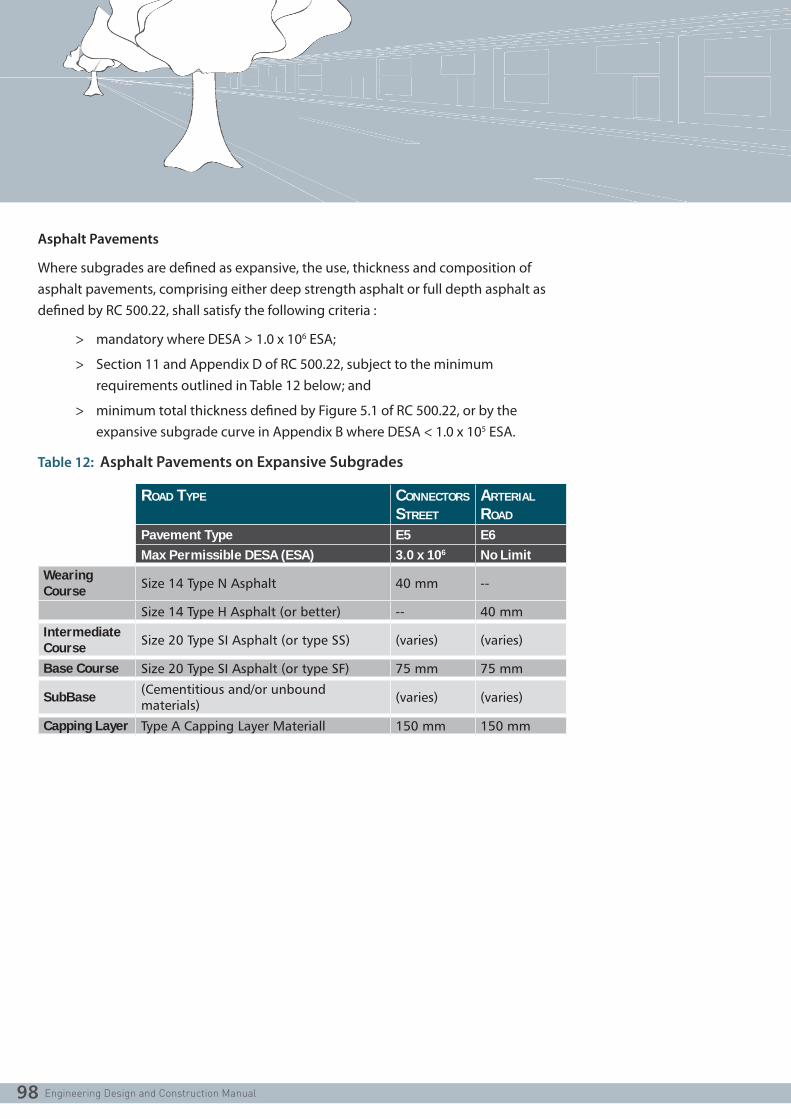
Asphalt Pavements
Where subgrades are defined as expansive, the use, thickness and composition of asphalt pavements, comprising either deep strength asphalt or full depth asphalt as defined by RC 500.22, shall satisfy the following criteria :
> mandatory where DESA > 1.0 x 10⁶ ESA;
> Section 11 and Appendix D of RC 500.22, subject to the minimum requirements outlined in Table 12 below; and
> minimum total thickness defined by Figure 5.1 of RC 500.22, or by the expansive subgrade curve in Appendix B where DESA < 1.0 x 10⁵ ESA.
Table 12: Asphalt Pavements on Expansive Subgrades
ROAD TYPE CONNECTORS STREET
ARTERIAL ROAD
Pavement Type E5 E6Max Permissible DESA (ESA) 3.0 x 10⁶ No Limit
Wearing Course Size 14 Type N Asphalt 40 mm --
Size 14 Type H Asphalt (or better) -- 40 mm
Intermediate Course Size 20 Type SI Asphalt (or type SS) (varies) (varies)
Base Course Size 20 Type SI Asphalt (or type SF) 75 mm 75 mm
SubBase (Cementitious and/or unbound materials) (varies) (varies)
Capping Layer Type A Capping Layer Materiall 150 mm 150 mm

99
11.8.3 Pavement Design Speeds
Unbound Granular Pavements
In view of the requirement for unbound granular pavements to be surfaced with two layers of asphalt as specified in Sections 11.8.1 and 11.8.2 above, the Granular Pavement Design Chart in Appendix B has been derived from mechanistic design procedures using CIRCLY on the basis of the following pavement design parameters :
> Project Reliability Level of 90%; and
> Pavement Design Speeds of both 10 km/h and 40 km/h, applicable for a designated speed limit of up to 60 km/h.
If there are circumstances for a particular project where the use of parameters other than those outlined above is warranted, designers will need to check their proposed designs in order to satisfy any necessary alternative design criteria.
This is particularly important in relation to the adoption of pavement design speeds as specified in RC 500.22 Table 11.1 for designated speed limits > 60 km/h. For the unbound granular pavements outlined in this guide, there would be a detrimental effect on the fatigue life of the asphalt surfacing because of the consequential elastic layer properties required to be used in the mechanistic design process.
Asphalt Pavements
Unlike the unbound granular pavements surfaced with two layers of asphalt discussed above, asphalt pavements, comprising either deep strength asphalt or full depth asphalt as defined by RC 500.22, will require thickening where the pavement is located in the following locations :
> at roundabouts and at signalised intersections; or
> where the designated speed limit is ≤ 40 km/h.
Designers are also required to pay particular attention to the selection of wearing course asphalt on Connector Streets and Arterial Roads in these locations where the computed HVs/lane > 500 hvpd in accordance with RC 500.22 Appendix D.

100
11.9 RIGID PAVEMENT DESIGN
Design of rigid pavements, including associated minimum requirements for pavement thickness and composition, and reinforcement and jointing design procedures, shall be undertaken in accordance with the design method outlined in Table 13 below.
Table 13: Rigid Pavement Design Method
DESIGN TRAFFIC DESIGN METHOD
< 1.0 x 10⁶ HVAG AGPT02 - Section 12.9
≥ 1.0 x 10⁶ HVAG RC 500.22 - Section 12
Where subgrades are defined as expansive, the following additional design criteria will also be required to be satisfied :
> minimum total pavement thickness defined by Figure 5.1 of RC 500.22, or by the expansive subgrade curve in Appendix B where DESA < 1.0 x 10⁵ ESA; and
> inclusion of a Capping Layer with a thickness ≥ 150 mm.

101
11.10 SUBSURFACE PAVEMENT DRAINS
11.10.1 General
Subsurface pavement drains shall be provided in association with all kerb and channel. The design and location of drains or filter blankets shall be carried out in accordance with the requirements of RC 500.22 Section 6.
11.10.2 Expansive Subgrades
Where the subgrade is classified as being expansive, subsurface pavement drains shall be designed to be contained wholly within the capping layer. In addition, no part of the subsurface drainage trench shall be located within 150 mm of the underlying subgrade. If necessary, the capping layer may have to be thickened to satisfy this
requirement.

102
12. EARTHWORKS DESIGN12.1 GENERAL
Objectives which should be met for earthworks and lot filling are:
> To ensure that development does not cause or aggravate flooding of other properties by filling land or undertaking other flood diversion works;
> To ensure that buildings are located on a natural surface above the 1% AEP flood level or on approved filled ground, so as to comply with the constraints of Regulation 6.2 of the Building Regulations 1994 and the Health Act;
> To ensure that the recommendations of the Catchment Management Authorities or other relevant agencies or organisations are complied with;
> To ensure earthworks and lot filling activities do not result in the spread of noxious weeds, as per Section 70A and 71 of the Catchment Management and Land Protection Act 1994;
> To ensure that earthworks and lot filling works does not result in erosion dust, mud or debris leaving the site; and
> To maintain privacy and security of adjacent landowners.
12.2 PLANNING & ENGINEERING REQUIREMENTS
Typical earthworks may include lot filling or the construction of open drainage systems, levees, access tracks, flood protection devices overland flow paths and vegetation removal.
Assessment of design submissions should focus on the above objectives and achievement of suitable road and drainage systems. Engineering approval does not negate the need for planning approval of such earthworks.
For any earthworks which are separate from subdivision works a planning permit shall be obtained and engineering plans submitted for approval shall be accompanied by a construction specification. Where works are to be staged it is recommended that consideration be given to the entire site and not individual stages. This will eliminate the need for multiple planning permits.
Existing depressions shall not be filled unless the consent of the Relevant Authority is given in writing, and any required permits obtained.

103
12.3 EARTHWORKS AND FILLING REQUIREMENTS
The following earthworks and lot filling requirements apply to all developments:
> All allotments shall be graded from either the rear to front or front to rear, by cutting or filling, such that a desirable minimum grade of 0.67% (1:150) is achieved from the high point of the allotment toward the low side of the allotment having the drainage outlet; an absolute minimum grade of 0.5% (1 in 200) will be considered in extreme circumstances. Grades shall be calculated along the side boundary of the allotment.
> The finished floor level of all buildings shall be a minimum of 300mm above the 100 year ARI flood level, or as otherwise specified in the planning permit or by the responsible drainage authority;
> The extent and depth of all proposed filling shall be shown on construction plans. Where depths of fill on allotments exceeds 200 mm, those areas are to be clearly differentiated from fill of depth less than 200mm;
> Full records shall be kept of all areas filled. The areas filled, the depths of fill and the finished surface levels shall be recorded on the “as constructed’ plans. Refer to Part D of this Manual for additional details regarding construction;
> Details of the safety and integrity of any structure shall be provided to the Council where earthworks abut structures;
> The desirable maximum depth of fill allowable against fencing is 200mm provided a suitable plinth is provided at the bottom of the fencing;
> Retaining walls are required when the depth of fill exceeds 500mm or maximum batter slopes are exceeded. Prior to designing retaining walls, the designer should discuss their proposal with Council;
> Concentrated stormwater runoff must not flow onto adjoining properties;
> Natural overland flow paths in adjoining properties must be accommodated and any restriction or alteration must not cause detriment to adjoining properties; and
> All reasonable precautions must be taken to prevent the spread of noxious
weeds from or to the worksite.

104
13. DRAINAGE DESIGN13.1 INTRODUCTION
This section of the Manual outlines the relevant standards necessary to meet best practice and accommodate various needs in relation to the design and construction of stormwater systems, and more generally to ensure the management of stormwater fits within an overall integrated water management approach for residential subdivision development.
Innovative or non-standard approaches to design may be considered subject to sufficient data and supporting details being provided on the philosophy and principles that are proposed.
The drainage design shall:
> Incorporate water quality and water quantity treatment measures to enhance quality of the drainage runoff before discharging it to a creek or other main drainage network; and
> Maintain pre-development flows at the outlet from the subdivision, unless otherwise approved by the responsible drainage authority.
Council is the responsible authority for all drainage works outside the authority of the relevant regional catchment management authority. All cross drainage works on creeks and waterways shall be to the approval of the regional catchment management authority. For other minor and major drainage, Council is the responsible drainage authority.
13.1.1 Stormwater and Water Sensitive Urban Design
Clause 56 of the Victorian Planning Provisions (urban runoff management objectives and Standard C25) requires that stormwater run-off from residential subdivisions in an urban area comply with the Urban Stormwater – Best Practice Environmental Management Guideline (BPEMG).
In particular cases, there may be specific Water Sensitive Urban Design Guidelines that are agreed between Melbourne Water and the relevant Council. Where these exist, there may be variations between particular Council areas.
Designers will therefore need to refer to any such specific guidelines.

105
13.1.2 Drainage Design References
Design and construction of stormwater management systems for residential development needs to be in accordance with the current edition/version of the following documents :
> “Urban Stormwater – Best Practice Environmental Management Guideline”, EPA, CSIRO, Melbourne Water et all;
> “Australian Runoff Quality Guidelines”, Engineers Australia;
> “Australian Rainfall and Runoff”, Institution of Engineers Australia, (AR&R);
> “Land Development Manual”, Melbourne Water;
> “Drainage Design Guidelines”, VicRoads;
> “Fibre Reinforced Concrete Pipes” 4139; and
> “Design for Installation of buried concrete pipes” AS 3725.
13.2 PLANNING & LAYOUT
Where required in proposed developments, the drainage system shall accommodate runoff from the upstream catchment, and provide for downstream drainage works.
Council and regional catchment management authority schemes shall be shown on plans.
Main drains should follow the valleys in reasonably straight alignments, with a minimum of deviation. Natural drainage paths shall be preserved, in the form of roadways, parkland, walkways, etc., and shall have a discharge capacity at least equal to that of the pipe drain.
Private allotments will not be permitted downstream of low points in roadways, downhill court bowls, or any other locations where drainage flows may concentrate.
Gap flows shall be confined to roadways and reserves and under no circumstances encroach onto private allotments. Freeboard is permitted to extend a limited distance into allotments in accordance with the provisions of Section 13.22.3 – Freeboard.

106
13.3 COMPUTATION OF RUNOFF
Computation of runoff shall be determined using the Rational Method:
Q = CIA/360Where Q = design discharge (m3/s)
C = runoff coefficientI = rainfall intensity (mm/h)A = catchment area (ha)
For large catchments the designer shall be responsible for ensuring that possible ‘Partial Area Effects’ are taken into account when calculating peak flows using the Rational Method.
Hydraulic programs using other than the Rational Formula may be permitted by Council.
13.4 RAINFALL INTENSITY
Australian Rainfall and Runoff shall be used to calculate rainfall intensities for the relevant location.
13.5 AVERAGE EXCEEDANCE PROBABILITY
The following values shall be used for drainage design; they do not apply for Water Sensitive Urban Design schemes.
Table 14: Average Exceedance Probabilities
Urban Residential Areas 20% (Q5)
Industrial and Commercial Areas 10% (Q10)
Floodways Gap Flow or 1% (Q100) if no pipe is provided

107
13.6 TIME OF CONCENTRATION
Table 15: Times of Concentration
DEVELOPMENT CATEGORY MAXIMUM TIME OF CONCENTRATION (TC) FOR FLOW TO ENTER SYSTEM (MINUTES)
AVERAGE RECURRENCE INTERVAL (YEARS)
Minor System - -
Road Reserves
Access Lane 5 5
Access Place 5 5
Access Street 6 5
Connector Street 6 5
Arterial Road 5 5
Parklands Calculated 5
Residential:
Block Area (m2) < 300 5 5
300 – 450 5 5
450 – 600 7 5
600-1000 7 5
1000 – 2000 7 5
2000 – 4000 7 5
> 4000 Calculated 5
Unit Development:
Dual Occupancy Block
(m2)
5 5
Major System Calculated MWC criteria
tc = t1 + t2 + t3where tc = time of concentration
t1 = time to reach the pipe or kerb and channelt2 = kerb and channel travel timeFrom Australian Rainfall and Runofft3* = pipe travel time From Australian Rainfall and Runoff; or
= L/Vwhere L= pipe length
*t3 shall be determined up to but not including the pipe reach being designed

108
13.7 RUNOFF COEFFICIENT ‘C’
Due to the variability of rainfall across Metropolitan Melbourne, runoff coefficients have not been standardised across all municipalities but have been calculated in accordance with the Australian Rainfall and Runoff (AR&R) Volume 1 (May 2003), Book VIII, Section 1.5.5 (iii) Runoff Coefficients.
The following formulas have been applied in calculating runoff coefficients for the growth areas:
C’10 = 0.1 + 0.0133 (10 I1 - 25)
Where C’10 is the pervious runoff coefficient10I1 is the 10 year ARI, 1 hour duration rainfall intensity
And; C10 = 0.9 ƒ + C’10 (1 - ƒ)
Where C10 is the 10 year ARI runoff coefficient.And; ƒ is the fraction impervious (0.0 to 1.0)
Cy = Fy C10
Where Cy is an average recurrence interval
Fy is a frequency factor
ARI (YEARS) FREQUENCY FACTOR, FY
1 0.80
2 0.85
5 0.95
10 1.00
20 1.05
50 1.15
100 1.20
Intensity Frequency Duration Data has been obtained from the Bureau of Meteorology website http://www.bom.gov.au/hydro/has/cdirswebx/index.shtml, using coordinates that are central to the area for which the runoff coefficient has been calculated.
To simplify the application of runoff coefficients, values have been limited to the 3 regions listed in Table 17.
Fraction impervious values for discrete sub-catchments of uniform use shall be taken from the ‘Typical Values’ column in Table 16 below. Averaging values across multiple use zones or allotment density as listed is not permitted.

109
Table 16: Land use fraction impervious
ZONE ZONE CODE BRIEF DESCRIPTION / EXAMPLES NORMAL RANGE TYPICAL VALUE
Residential Zones:Residential 1 & 2 Zone
R1Z Normal range of densities. (Allotment size 600m2 – 1000m2)
0.40 - 0.60 0.50
R2Z Medium densities. (Allotment size 450m2 – 600m2)
0.50 – 0.70 0.60
High densities. (Allotment size <450m2)
0.70 – 0.90 0.80
Low Density Residential Zone
LDRZ Low densities (Allotment size 1000m2-4000m2.)
0.15 - 0.45 0.30
Mixed Use Zone MUZ Mix of residential, commercial, industrial & hospitals.
0.60 - 0.90 0.70
Township Zone TZ Small townships with no specific zoning structures.
0.40 - 0.70 0.55
Industrial ZonesIndustrial 1 Zone IN1Z Main zone to be applied in most
industrial areas.0.70 - 0.95 0.90
Industrial 2 Zone IN2Z Large industrial zones away from residential areas.
0.70 - 0.95 0.90
Industrial 3 Zone IN3Z Buffer between Zone 1 and Zone 3. 0.70 - 0.95 0.90
- for garden supplies/nurseries. 0.30 - 0.60 0.50
- for quarries. 0.10 - 0.40 0.30
Business ZonesBusiness 1 Zone B1Z Main zone to be applied in most
commercial areas.0.70 - 0.95 0.90
Business 2 Zone B2Z Offices and associated commercial uses.
0.70 - 0.95 0.90
Business 3 Zone B3Z Offices, manufacturing industries & associated uses.
0.70 - 0.95 0.90
Business 4 Zone B4Z Mix of bulky goods retailing & manufacturing industries.
0.70 - 0.95 0.90
Business 5 Zone B5Z Mix of offices & multi-dwelling units.
0.70 - 0.95 0.90
Rural Zones:Rural Zone RUZ Main zone to be applied in most
rural areas.0.05 - 0.20 0.10
Environmental Rural Zone
ERZ Rural areas with specific environmental considerations.
0.05 - 0.20 0.10
Rural Living Zone RLZ Predominantly residential use in rural environment.
0.10 - 0.30 0.20
Public Land ZonesPublic Use Zone Use of land for public purposes
- Service and Utility
PU1Z - power lines, pipe tracks and retarding basins.
0.20 - 0.30 0.25

110
- reservoirs. 0.40 - 0.60 0.50
- Education PU2Z - schools and universities. 0.60 - 0.80 0.70
- Health and Community
PU3Z - hospitals. 0.90 - 0.80 0.70
- Transport PU4Z - railways and tramways. 0.60 - 0.80 0.70
- Cemetery / Crematorium
PU5Z - cemeteries and crematoriums.
0.50 - 0.70 0.60
- Local Government
PU6Z - libraries, sports complexes and offices / depots.
0.70 - 0.90 0.80
- Other Public Use
PU7Z - museums. 0.50 - 0.80 0.60
Public Park and Recreation Zone
PPRZ Main zone for public open space, incl golf courses.
0.20 - 0.30 0.25
Public Conservation and Resource Zone
PCRZ Protection of natural environment or resources.
0.05 - 0.25 0.25
Road Zone – Category 1
RDZ1 Major roads and freeways. 0.60 - 0.90 0.75
Road Zone – Category 2
RDZ1 Secondary and local roads. 0.50 - 0.80 0.60
Special Purpose Zones :Special Use Zone SUZn Development for specific
purposes.0.50 - 0.80 0.60
Comprehensive Development Zone
CDZn Large and complex developments – residential.
0.40 - 0.80 0.50
Urban Floodway Zone
UFZ Land identified as part of an active floodway.
0.05 - 0.25 0.25
Capital City Zone CCZn Special Use Zone for land in Melbourne’s central city.
0.70 - 0.90 0.80
Docklands Zone DZn Special Use Zone for land in Docklands area.
0.70 - 0.90 0.80
Commonwealth Land :
Commonwealth Land
CA Army barracks, CSIRO. 0.50 - 0.80 0.60
To simplify the number of coefficients applied, runoff coefficients have been limited to the 3 regions listed in Table 17

111
Table 17: “C” Values
SOUTH-EAST REGION – CARDINIA & CASEY
C’100.11508008
ƒ C5 C10 C100
0.2 0.258 0.272 0.326
0.5 0.482 0.508 0.609
0.6 0.557 0.586 0.703
0.7 0.631 0.665 0.797
0.8 0.706 0.743 0.892
0.9 0.780 0.822 0.986
1.0 0.855 0.900 1.000
SOUTH-WEST / WEST REGION – WYNDHAM & MELTON
C’100.15445632
ƒ C5 C10 C100
0.2 0.288 0.304 0.364
0.5 0.501 0.527 0.633
0.6 0.572 0.602 0.722
0.7 0.643 0.676 0.812
0.8 0.713 0.751 0.901
0.9 0.784 0.825 0.991
1.0 0.855 0.900 1.000
NORTH-WEST REGION – HUME & WHITTLESEA
C’100.16031382
ƒ C5 C10 C100
0.2 0.293 0.308 0.370
0.5 0.504 0.530 0.636
0.6 0.574 0.604 0.725
0.7 0.644 0.678 0.814
0.8 0.714 0.752 0.902
0.9 0.785 0.826 0.991
1.0 0.855 0.900 1.000

112
13.8 HYDRAULICS
Drainage design shall be based on hydraulic grade line analysis, using appropriate pipe friction and drainage structure head loss coefficients. All pipe sizes are to be computed using a velocity and discharge diagram based upon Manning’s equation. HGL’s shall be shown on drainage plans.
13.9 HYDRAULIC GRADE LINE
The hydraulic grade line shall be at least 300mm below the surface or kerb or channel invert, and not more than 2m above the pipe obvert.
13.10 PIPE GRADE AND ALIGNMENT
Pipes shall be uniformly graded and generally designed in a straight line between pits. Curved pipelines are permitted only where they are of constant radius and in accordance with the pipe manufacturer’s specifications.
13.11 MINIMUM COVER (TO TOP OF PIPE)
Under road pavements for concrete pipes, the greater of 750mm below design surface level or 150mm below pavement depth (including any capping layer).
NOTE: Pipe Class may need to be increased if cover is not sufficient under subgrade due to construction traffic loading
Elsewhere 450mm for concrete pipes subject to pipe class requirements
The design of pipe cover shall consider the effects of all utility services and conduits and provide the necessary clearances required by the relevant utility authority. The design shall also consider the control of sub surface drains (refer Clause 13.24)
13.12 PIPE FRICTION
Table 18: Friction Factors
MANNING COLEBROOK - WHITE
N k (mm)
Concrete 0.013 0.6
Other MaterialsTo Manufacturer’s
specificationTo Manufacturer’s specification

113
13.13 MINIMUM PIPE SIZE
Easement: 150mm; for grades flatter than 1 in 150 minimum pipe size to be 225mm.
Within road reservation: 225mm but 300mm where road runoff is being collected or the pipe crosses the road
A reduction in the size of pipes may be permitted for 450mm pipes and above.
13.14 PIPE JOINTS
All pipes up to and including 750mm in diameter shall be rubber ring jointed. Pipes above this size may be flush jointed with external sealing bands.
For pipes greater than 900mm and changes in direction between 2 connecting pipes exceeding 10o construct segmented curves using splayed pipes with bandage joints, having deflections within the manufacturer’s specification.
13.15 PIPE FLOW VELOCITY AND GRADE
The following is based on pipes running full but not under pressure.
Table 19: Acceptable Velocities
DESIRABLE GENERAL FLAT TERRAIN STEEP TERRAIN
Minimum 1.0 m/s 0.9 m/s 0.6 m/s NA
Maximum 4.0 m/s 5.0 m/s NA 6.0 m/s

114
13.16 ANCHOR BLOCKS
Anchor blocks shall be provided where the pipe slope is steeper than 1 in 6 and the pipe length is greater than 15m. Refer to the attached standard drawings for details of anchor block construction.
13.17 ALIGNMENT AT PITS
Where possible, drops and deflections shall be kept to the minimum requirements to maintain the flow through pits as a jet and minimise head loss created by turbulence.
Required drops (at invert):
> Generally 50mm to 100mm for same size pipes.
> Match springing lines for change in diameter, but a drop shall not be less than 50mm.
> Drops in the range 100mm to 1.5Do are not permitted except: – where springing lines are matched. – for minor branches - (Db < 2/3 DO ) (Db = branch diameter) (D o = outlet
diameter) – to dissipate head in steep terrain.
> Drops greater than 1.5Do are acceptable on long pipe reaches (where there are considerable savings in excavation) for pipe sizes up to 450mm.
The maximum permitted deflections in pits are:
Do ≤ 600mm 0o - 50o : align as in standard detail
50o - 90o : provide deflector in pit floor
>90o : not permitted
Do 675mm – 900mm Maximum deflection - 45o
Do ≥ 1050mm Maximum deflection – 10o

115
13.18 PIT LOCATIONS
Pits should, preferably, be located at or about the mid-point of the frontage of allotments, to reduce the likelihood of conflict with future driveway locations.
Pits shall be located a minimum clearance of 1m from a vehicle crossing.
13.19 KERB INLETS
Pits shall be spaced to capture all surface flow resulting from the design minor rainfall event with a maximum spacing of 90m.
Kerb inlets are required at the following locations:
> Adjacent to tangent points at intersections where the channel falls towards the intersection;
> At low points; and
> At construction boundaries, unless existing drainage inlets downstream are adequate.
> Additional kerb inlets shall be provided at;
> Double entry pits at low points of streets where one or both channel grades are greater than 7%.
> Flat vertical curves approximately 10m either side of the low point, except where saw tooth grading of the kerb is employed.
A 50% blockage factor shall be allowed when designing the inlet capacity of grated entry pits at low points.
13.20 PIT HEAD LOSSES
To be calculated using procedure in the ARR and AustRoads design procedures.
13.21 PROPERTY CONNECTIONS
A property connection shall be placed at the lowest point of each property.
Stormwater outlets for all allotments shall be connected to an underground drain.
Whenever depth of a connection is critical for adequate lot control the invert level shall be calculated and shown on the plans.
Refer Standard Drawings for the property connection arrangement.

116
13.22 SURFACE DRAINAGE
13.22.1 Flow
The maximum depth of flow in a channel, for a 20% AEP design storm, shall be 0.14m for barrier type kerb and channel and 0.11m for SM2 roll-over type kerb and channel.
The maximum width of flow in the channel and roadway for a design storm shall not be greater than 3.0m, or the width of a parking lane if one is provided.
In locations where the level at a property line is below the kerb level, care should be taken to ensure the maximum allowable depth of flow is not exceeded.
Where a low point occurs in a longitudinal road grading or at the end of a court bowl, the footpath or fixed level at the property line shall be designed to prevent inundation of adjoining lots while providing for any overland flow path required for the 1% AEP runoff.
13.22.2 Gap Flows
The maximum depth and velocity of flow along an overland flow path for a 1% AEP design storm shall be in accordance with relevant requirements including the Melbourne Water ‘Land Development Manual’.
13.22.3 Freeboard
Finished levels of allotments adjacent to overland flow paths for a 1% AEP design storm should ensure gap flows are retained in the road reserve. The 150mm freeboard (i.e. the level 150mm above the gap flow level) will be allowed to extend a maximum of 2.0m into the lot.
13.22.4 Overland Flow Paths
Trapped low points in streets and reserves adjacent to private property shall only be permitted where an overland flow path can be provided for the 1% AEP design storm clear of private property and unencumbered open space. The use of surface grates and pipes with capacity exceeding the 20% AEP design shall not be relied upon to avoid the provision of the overland flow path.

117
13.23 WATER QUALITY
Where required, drainage design will incorporate water quality treatment measures to enhance quality of the drainage runoff before discharging into waterways or other main drainage networks.
Water Sensitive Urban Designs shall be prepared in consultation with Council’s engineering and planning departments and in accordance with the requirements of MWC’s publication “WSUD Engineering Procedures”.
13.24 SUB SURFACE DRAINAGE
Sub surface drainage is to be provided as indicated in the attached standard drawings and shall discharge into pits at a level above the highest obvert of any stormwater pipe open to the pit.
In situations where the swell potential of the sub grade is 2.5% or more (i.e. highly expansive subgrade), a continuous unbroken capping layer is generally required. In these cases the invert of the sub surface drain is to be raised such that it drains the pavement only. Trenches for the sub surface drains must not be below the capping layer into the subgrade.
Provision should be made for “flush-out-risers” at crests in accordance with standard
drawings and the construction specification.

118
14. UTILITY SERVICE CONDUITS14.1 UTILITY SERVICE CONDUITS
14.1.1 Location
Service conduits to each allotment, on the opposite side of the road to the proposed utility main, shall be provided under the pavement of all subdivision roads. Conduits are also required under footpaths and retaining walls. Generally, conduits should be located towards the centre of residential allotments.
14.1.2 Cover
The minimum cover to conduits is 450mm below the finished pavement surface, or within the subgrade layer, whichever is the deeper. Conduits shall not be placed within the pavement nor capping layers. Conduits are to be laid at a grade of 1 in 100 falling to the side of the proposed utility main.
14.1.3 Marking
The position of the conduit is to be marked on the face of the kerb on each side of the road with a 50mm high letter (i.e. G for gas conduit and W for water) imprinted into the concrete.
14.1.4 Trench Backfill
Trenches in which conduits are laid shall be backfilled with approved material as specified. Where a capping layer is required as a part of the pavement, conduits shall be installed prior to placing the capping layer to provide an unbroken capping layer.
14.1.5 Conduit Pipes
Conduit pipes are to be in the following sizes:
Residential Allotments: 50mm
*All other requirements for conduits shall be in accordance with Council Specifications.

119
14.2 FIBRE TO THE PREMISE (FTTP) NETWORK
Installation of optic fibre conduits and pits should be in accordance with the NBN Co “Installing Pit and Conduit Infrastructure – Guidelines for Developers.”
Where separate telecommunications conduits are required by Council, the individual council should be contacted in regard to particular requirements
General requirements for optic fibre conduits and pits for growth areas are outlined as follows.
14.2.1 Layout
Plans are to show an outline functional layout including as a minimum trees, title boundary, kerbs, footpaths, crossings, drainage, other services and any likely points of conflict.
14.2.2 Offsets
Conduit offsets within roads, easements and reserves shall be in accordance with the approved Functional Layout Plans for the subdivision. A “Table of Services Offsets” shall be included on the optic fibre layout plans.
14.2.3 Easements Required
In building (body corporate) subdivisions shared easements shall be provided for optic fibre conduits and underground electrical cables between the “point of supply” and each dwelling/site.
14.2.4 Property Services – Location
Property service conduits shall be located not less than 6.0 metres offset from the property boundary and with 150 mm clearance from all drainage, water and gas connections to the property.
14.2.5 Road Crossings
At road crossings and across shared driveways the following termination arrangement shall apply:-
> Residential – termination either in pit(s) or cap 500 mm inside the property boundary.
> Industrial/commercial – termination in pit(s).

120
14.2.6 Pit Locations
Optic fibre pits shall be located clear of all pedestrian and vehicular pavements and 1.0 metre from driveway crossings.
14.2.7 Launch Pits
“Launch Pits”, shall be provided at the “Limit of Works” where further stages or an adjoining future subdivision will abut.
14.2.8 Additional Provision
Where appropriate Planning Provisions are in place, a planning permit condition may require linkage beyond the subdivision. When linkage beyond the site has been required the overall length of additional underground network is to be identified and the proposed location discussed with Council.
14.2.9 Shared Trenching
If the proposed design proposes shared trenches (horizontal or vertical separation) longitudinally and/or across roads, a “Trenching Agreement” is required with the other service providers affected. Such trenching agreement(s) are to be submitted to Council
for approval with the plans.

121
15. STRUCTURAL ELEMENTS15.1 GENERAL
When an item of infrastructure, whether part of the road and drainage works or hard landscaping, contains any structural element the following criteria should be satisfied.
15.2 DESIGN CRITERIA
> Joint spacing, type, location, construction details and pouring sequence for concrete pavements shall be shown on plans for each type of concrete pavements (roads or pedestrian). Pavement design computations must be submitted to Council for review and approval.
> Pavement joints and spacing details for standard concrete footpaths shall be in accordance with the Standard Drawings.
> Concrete type and grade must be clearly stated on plans.
> All design loadings, material specifications and structural design must be in accordance with the applicable Australian Standards.
> Design criteria for each structural element must be clearly shown in the structural computations provided to Council.
> Unless noted otherwise, all structures must be designed for the following durability criteria:
Table 20: Durability Criteria
STRUCTURE TYPE LIFE SPAN (YEARS)Bridges/Culverts 100
Structures Supporting Road Infrastructure (retaining walls, etc)
100
Boardwalks, shelters, pergolas, major street furniture and art supporting structures
25
General (if not specified in this table) 25
Temporary Structures To be discussed with Council

122
> Concept Design including a design criteria shall be submitted to Council for approval prior to submission of the final documents.
> Copies/size of plans for submissions shall be in accordance with Council’s general engineering approval requirements. A copy of structural computations and design certificates must be provided.
> Structural and civil engineering designs submitted in a package with landscape works shall be presented on a separate plan(s) indicating all construction details but excluding cladding or architectural details, additional finishes and ‘soft landscaping’ details.
> Any balustrades that prevent falls from heights greater than 600 mm shall be designed in accordance to the relevant Australian Standards.
> All exposed steelwork shall be hot-dip galvanised. All timber grades and types adopted must be in accordance with the durability criteria as specified in Australian Standards or as directed by Council.
> Steelwork connections shall bolted or pre-welded (shop-welded) and hot dip galvanized. On site welding is not acceptable unless it is demonstrated that there is no other connection method possible.
> Copies of Geotechnical Engineering reports shall be provided together with the foundation computations. Bearing pressures specified on plans must be verified by a qualified geotechnical engineer on site prior to construction.

123
15.3 CONSTRUCTION SUPERVISION & CERTIFICATES
> During construction Council Officers shall be notified of all hold points unless confirmed otherwise by Council as part of design approval.
> Contractor/Developer shall ensure that a registered building practitioner is supervising all structural works on site and, at the completion of the construction works, provide a Certificate of Compliance – Construction which verifies that the construction works were completed in accordance with the approved design plans.
> A copy of all Site Inspection Reports shall be forwarded to Council for its records.
> A copy of the standard structural details and/or shop drawings shall be provided to Council, together with the “As Constructed” documentation (unless issued by Council as a “Standard Drawing”).
> As constructed plans shall be provided prior to Council’s acceptance of Practical Completion (for the purpose of a Statement of Compliance).
> Defects Liability Period (DLP) applied to the structures will be in accordance with the requirements of the Planning Permit.

124
15.4 BRIDGES
15.4.1 Basis for Design
All bridge design shall be in accordance with the current version of AS5100.
15.4.2 Certification
All bridge design must be certified by an independent qualified bridge engineer prequalified by VicRoads.
15.4.3 Bridge Cross Section
A minor structure (whether bridge or box culvert) with the top of the deck at road level, with a length measured along the centre line of the road of 6.0m or less, shall extend the full width of the road reserve.
A bridge, or box culvert with the deck at road level, with a length measured along the road centreline of greater than 6.0m, shall have a width between kerbs equal to that of the approach road ( i.e. the road in which it is located) plus provision for pedestrians and cyclists.
In the case of roads with dual carriageways, a bridge is to be built on the alignment and width between kerbs (excluding emergency stopping lanes) of each pavement plus provision for pedestrians and cyclists.
15.4.4 Footway Clearance
A pedestrian footway shall have a clear width of not less than 3.0m, from the inside face of the handrail to the back of the kerb.
15.4.5 Fencing and handrailing
Protective fencing is to be extended to a point where the slope becomes less than 25%.
All bridge railing and pedestrian fencing shall be designed for pedestrian loading and vehicle impact and comply with The Building Code of Australia.
15.4.6 Surfacing
A bridge or box culvert with the deck at road level shall be surfaced with asphaltic
concrete of minimum thickness 50mm.

125
16. ASSOCIATED INFRASTRUCTURE16.1 GENERAL
Associated infrastructure are the additional infrastructure not specified elsewhere in this manual and will generally comprise street furniture, street lighting, utilities such as water and gas reticulation, sewerage, power and lighting and communications networks. Increasingly utilities will also include provision for recycled water and broadband data.
16.2 PRINCIPLES
The principles associated with providing associated infrastructure are as follows:
> All associated infrastructure to be vested in the Council shall meet Council’s requirements and standards.
> The urban character and amenity of a locality, neighbourhood or development shall not be adversely impacted by the associated infrastructure.
> The location of the associated Infrastructure shall not conflict with other existing or proposed services and Council Infrastructure.
> The requirements of all servicing authorities shall be considered before giving approval for any particular service.
> The requirements of any relevant Codes of Practice, Australian Standard, regulation or act of parliament shall be considered by Council before approving the type and location of any associated infrastructure.
16.3 WATER SUPPLY
The design, documentation and installation of reticulated water supply required to service the development shall be in accordance with the relevant Authority requirements.
The Consultant/Developer is responsible for liaising and co-ordinating with the Authority responsible for water infrastructure.
The location and spacing of fire hydrants are generally to be to the satisfaction of the responsible fire authority (Country Fire Authority). However in some instances, this responsibility may be transferred to Council.
Design Standard used by Water Authorities is WSA03 (Melbourne Retail Water Authority Version).

126
16.4 RECYCLED WATER
The design, documentation and installation of all recycled water supply required to service the development shall be in accordance with the relevant Authority criteria, specifications and instructions.
The Consultant/Developer is responsible for liaising and co-ordinating with the Authority responsible for recycled water infrastructure.
Design Standard used by Water Authorities is WSA03 (Melbourne Retail Water Authority Version).
16.5 SEWER
The design, documentation and installation of all reticulated sewerage required to service the development shall be in accordance with the relevant Authority criteria, specifications and instructions.
The Consultant/Developer is responsible for liaising and co-ordinating with the Authority responsible for sewerage infrastructure.
Design Standards used by Water Authorities are WSA03 (Melbourne Retail Water Authority Version) in conjunction with WSA Dual Water Supply Systems code.
16.6 GAS
The design, documentation and installation of all related gas reticulation required to service the development shall be in accordance with the relevant Authority criteria, specifications and instructions.
The Consultant/Developer is responsible for liaising and co-ordinating with the Authority responsible for gas infrastructure.
16.7 ELECTRICITY
16.7.1 Design
The design, documentation and installation of all electrical infrastructure required to service the development shall be in accordance with the relevant Authority criteria, specifications and instructions.
The Consultant/Developer is responsible for liaising and co-ordinating with the Authority responsible for electricity infrastructure including public lighting.

127
16.7.2 Electricity Sub Station/Kiosk Location
Utility service substation/kiosk sites must only be located on any land identified as public open space or to be used for any municipal purposes if agreed by the responsible authority.
Placement of electricity sub station/kiosks is subject to:
> Access for installation and maintenance purposes.
> Providing an appropriate landscape treatment to screen the installation.
16.8 TELECOMMUNICATIONS AND DATA
The design, documentation and installation of all telecommunications reticulation required to service the development shall be in accordance with the relevant Authority criteria, specifications and instructions.
The Consultant/Developer is responsible for liaising and co-ordinating with the authorities responsible for telecommunications including FTTP.
16.9 PUBLIC LIGHTING
The objective for the provision of public lighting is:
> Consistent, equitable and environmentally responsible public lighting that appropriately caters for the safety and security of all sectors of the community.
16.9.1 Provision for Public Lighting
All roads within the new subdivision shall be provided with public lighting in accordance with the requirements of the relevant Australian Standards. New lighting shall be located outside the clear zones wherever possible, and shall meet the standards for Category V or Category P lighting, as appropriate.
Category V lighting is applicable on roads where visual requirements of motorists are dominant, such as sub-arterial roads. Category P lighting is applicable on roads (and other public outdoor areas) where the visual requirements of pedestrians are dominant, such as local roads and outdoor shopping precincts.
All public lighting shall incorporate the use of energy efficient globes (eg.T5, CFL or similar).
16.9.2 Decorative and Non-Standard Lighting
Where decorative or non-standard lighting is permitted by Council, lamps and luminaires shall comply with the Public Lighting Service Provider’s technical requirements and shall be approved by Council.

128
16.9.3 Non-standard Lighting Fee
Where decorative or non-standard street lighting is permitted by Council, Council will require payment of a fee prior to the release of lots within that stage of development.
Non-standard pole and lantern types shall be in accordance with Council’s general lighting policies.
16.9.4 Lighting Design
Lighting design shall be in accordance with the relevant Australian Standards, including the current issue of AS/ANZ 1158 – Lighting for Roads and Public Spaces.
Lighting installations for Arterial Roads and associated intersections are reviewed and approved by VicRoads as the responsible coordinating road authority. Copies of drawings shall be forwarded to Council for assessment after which advice will be forwarded to VicRoads prior to approval.
Allowance for pole locations shall be provided within all road reserves and offsets are to be shown in “Service Location Tables” on FLP’s and Road Construction Plans.
A minimum 800mm offset shall be provided from back of kerb to pole for all roads with P category lighting, including laneways and shared zones where kerbing is provided.
A minimum 1000mm clearance is required from face of pole to:-
> Edge of carriageway in laneways, shared zones and extended driveways where no kerbing is provided. Kerb outstands may be requested for pole protection in some circumstances,
> Edge of pram crossings and private vehicle crossings within nature strips.
“Easy Fit” pole bases/foundations are required where maintenance access is restricted (e.g. in laneways, “paper roads” and shared driveways).
With the exception of lighting in speed zones of 50 km/hr or less, frangible poles shall be adopted for roads with V category lighting in accordance with AS 1158 – Lighting for Roads and Public Places. The specific pole type (impact absorbing or slip base) shall be determined according to VicRoads standards and shall be nominated on the drawings.
Provision of public lighting is required for all principal footpaths and bike paths within parks and reserves of any development. All cabling for this purpose shall be from a metered point of supply at the reserve boundary and Council will accept responsibility for the tariff.
Bollard lighting is acceptable only in reserves where vertical illumination is not required for the relevant lighting category.
Lighting obstructions (e.g. from existing large trees) shall be taken into account when locating poles and assessing luminance requirements.

129
16.9.5 Pre-submission requirements
Prior to the submission of Public Lighting Plans the following shall be confirmed with Council:
> Lighting design categories for all roads and pathways;
> Locations of all principal pathways in parks/reserves outside road reserves;
> Locations and type of other items/structures that may require public lighting;
> Style and colour of non-standard poles and fittings and type of lantern; and
> A Functional Layout Plan has been endorsed in accordance with any planning permit requirement.

130
16.10 PERMANENT SURVEY MARKS
New permanent survey marks shall be documented and installed in appropriate locations for the future use of Council and Licensed Surveyors generally.
Contact Council for details of local requirements such as location, spacing and formal registration by a Licensed Surveyor upon completion.
16.11 STREET NAME SIGNS
All subdivisions require the installation of street name signs generally in accordance with AS 1742.5 – Manual of Uniform traffic control devices – Street name and community facility name signs. Contact Council for details of local requirements for type, style and content.


![SIGHT DISTANCE - FEET DECISION SIGHT DISTANCE 1Upper Minimum . Minimum : 1 . Stopping Sight Distance (SSD) to a 6-inch object SSD to a 24-inch object: 2 [BOTH] Decision Sight Distance](https://static.fdocuments.in/doc/165x107/5e758853d718f15f1c0c0fb3/sight-distance-feet-decision-sight-distance-1-upper-minimum-minimum-1-stopping.jpg)