PART – B (DETAILED TECHNICAL SPECIFICATION) SUB-SECTION …
116
DCRTPP YAMUNA NAGAR (2X300 MW) FLUE GAS DESULPHURISATION (FGD) SYSTEM PACKAGE TECHNICAL SPECIFICATION SECTION-VI BID DOCUMENT NO.: 4/CE/PLG/NTPC/DCRTPP/FGD-251 PART – B (DETAILED TECHNICAL SPECIFICATION) SUB-SECTION-II-E (ELECTRICAL SYSTEM)
Transcript of PART – B (DETAILED TECHNICAL SPECIFICATION) SUB-SECTION …

DCRTPP YAMUNA NAGAR (2X300 MW) FLUE GAS DESULPHURISATION (FGD)
SYSTEM PACKAGE
TECHNICAL SPECIFICATION SECTION-VI
BID DOCUMENT NO.: 4/CE/PLG/NTPC/DCRTPP/FGD-251
PART – B (DETAILED TECHNICAL SPECIFICATION)
SUB-SECTION-II-E (ELECTRICAL SYSTEM)

DCRTPP YAMUNA NAGAR (2X300 MW) FLUE GAS DESULPHURISATION (FGD)
SYSTEM PACKAGE
TECHNICAL SPECIFICATION SECTION-VI
BID DOCUMENT NO.: 4/CE/PLG/NTPC/DCRTPP/FGD-251
SUB-SECTION-II-E1
GENERAL ELECTRICAL SPECIFICATION

CLAUSE NO.
TECHNICAL REQUIREMENTS
DCRTPP YAMUNANAGAR (2X300MW) FLUE GAS DESULPHURISATION (FGD)
SYSTEM PACKAGE
TECHNICAL SPECIFICATION SECTION-VI, PART-B
BID DOC. NO.: 4/CE/PLG/NTPC/DCRTPP/FGD-251
SUB SECTION-II-E1 GENERAL ELECTRICAL
SPECIFCIATION
PAGE 1 OF 8
1.00.00 General Requirements
1.01.00 For the purpose of design of equipment/systems, an ambient temperature of 50 deg. Centigrade and relative humidity of 95% shall be considered. The equipment shall operate in a highly polluted environment. However, for equipment in air conditioned areas, design ambient temperature shall be 35 deg.C, if 2x100% air conditioning system is provided unless specified specifically in relevant sub sections.
1.02.00 All equipment shall be suitable for rated frequency of 50Hz with a variation of +3% & -5%, and 10% combined variation of voltage and frequency unless specifically brought out in the specification.
1.03.00 Contractor shall provide fully compatible electrical system, equipment, accessories and services for the entire station/plant in his scope as well as those specifically required by the Employer.
1.04.00 All the equipment, material and systems shall, in general, conform to the latest edition of relevant National and International Codes & Standards, especially the Indian Statutory Regulations.
1.05.00 The auxiliary AC voltage supply arrangement shall have 11 kV/3.3kV or 6.6 KV and 415V systems. It shall be designed to limit voltage variations as given below under worst operating condition:
a) 11KV/3.3KV/6.6 KV (MV) +/- 6%
b) 415 V/240 V +/- 10%
c) 220V/110V DC -15% to +10%
1.06.00 The voltage level for motors shall be as follows:
a) Upto 0.2 KW : Single phase 240V AC / 3 phase
415V AC
b) Above 0.2 KW and upto 200 KW : 3 phase, 415V AC
c) Above 200 KW and upto 1500 KW : 3 phase, 3.3kV or 6.6kV AC
d) Above 1500 KW : 11 kV/6.6kV AC*
*Wherever only 6.6 kV & 415V is indicated in Electrical SLD, all motors above 200kW shall be 6.6 kV. Final selection of voltage levels shall be as per relevant tender SLD.

CLAUSE NO.
TECHNICAL REQUIREMENTS
DCRTPP YAMUNANAGAR (2X300MW) FLUE GAS DESULPHURISATION (FGD)
SYSTEM PACKAGE
TECHNICAL SPECIFICATION SECTION-VI, PART-B
BID DOC. NO.: 4/CE/PLG/NTPC/DCRTPP/FGD-251
SUB SECTION-II-E1 GENERAL ELECTRICAL
SPECIFCIATION
PAGE 2 OF 8
The bidder may adopt 415V/3.3 KV or 6.6kV for the drives rated in the range of 160-210 KW.
Voltage rating for special purpose motors viz, VFD shall be as per manufacturer’s standard.
1.07.00 The preferred AC control supply voltage shall be 110V for all 415 V non breaker controlled feeders. Control supply voltages other than above may be offered by bidder based on the bidder’s standard proven practice.
1.08.00 The designed fault levels for various voltage levels shall be restricted to the following values:
11 kV- 40 kA rms for 1 sec
3.3kV/6.6 kV- 40 kA rms for 1 sec
415 V- 50kA rms for 1 sec
Bidder shall submit suitable system studies and calculations to this effect during detailed engineering.
1.09.00 The Contractor shall furnish calculations of maximum loading and fault levels under the most onerous conditions for the various equipment/systems as defined elsewhere in the specification to prove adequacy of their parameters. In case any equipment or system is found to be inadequate, it shall be changed/ modified without any additional liability to the Employer.
1.10.00 Transformer voltage ratios, taps, impedances and tolerances thereon, shall be so optimized so that the auxiliary system voltages under various loading conditions are always within permissible limits and equipment are not subjected to unacceptable voltages during operation and starting of motors. The vector groups of the transformers shall be so selected that all the buses of particular voltage level have same vector within the plant.
1.11.00 In fire hazardous areas like gas/ liquid fuel storage/ handling areas, lighting fixtures, switchgears shall be flame proof.
1.12.00 The responsibility of coordination with electrical agencies /TAC/Pollution control board and obtaining all necessary clearances shall be of the contractor.
1.13.00 Provenness Criteria
Provenness of the Equipment, system, being offered by the bidder should satisfy the criteria Indicated in the “Provenness criteria” indicated elsewhere in the specification.
CLAUSE NO.
TECHNICAL REQUIREMENTS
DCRTPP YAMUNANAGAR (2X300MW) FLUE GAS DESULPHURISATION (FGD)
SYSTEM PACKAGE
TECHNICAL SPECIFICATION SECTION-VI, PART-B
BID DOC. NO.: 4/CE/PLG/NTPC/DCRTPP/FGD-251
SUB SECTION-II-E1 GENERAL ELECTRICAL
SPECIFCIATION
PAGE 3 OF 8
2.00.00 SIZING & DESIGN
2.01.00 Transformers
All the transformers shall be sized based on the maximum load expected to be fed by them under most onerous conditions or as per the rating indicated in the Electrical Single Line Diagram.
All Auxiliary transformers (unless their ratings have been indicated in Single line Diagram or for which sizing criteria has been indicated in the specification), shall be sized so as to have 10% margin at design ambient conditions after considering final load requirements, including owner’s load (if applicable), at peak load conditions and the No Load Voltage Correction Factor.
Transformer size = The calculated size X no load voltage correction factor (11.5/11, 3.45/3.3, 6.9/6.6, 0.433/0.415).
No Load Voltage Correction Factor (= Transformer No Load voltage/ rated bus Voltage) shall be used for sizing of all transformers.
2.01.01 Adequate number of auxiliary transformers shall be provided to meet the demand on 11kV and 3.3kV or 6.6kV and 415V systems under most onerous conditions, with the criteria that each 11kV / 3.3KV / 6.6KV/ 415 V switchgear / MCC / DB shall be fed by 2x100% or 3 X 50 % transformers / feeders, and these shall be rated to carry the maximum load expected to be imposed.
2.01.02 The overall system shall be such that failure of any one unit auxiliary transformer, DC battery and Battery charger shall not reduce the capability or affect the safe shut down requirements of the FGD System.
2.02.00 MV Switchgears
Sizing of HT Switchgears (11kV/6.6kV/3.3 kV) shall be in accordance with Clause No. 1.00.00 of Sub-section E8 and its sub-clauses covering sizing criteria, standardization, etc.
The switchgear boards shall have a single front, single tier, fully compartmentalized, metal enclosed construction complying with clause No. 3.102 of IEC 62271-200, comprising of a row of free standing floor mounted panels. The Service Class Continuity of Switchgears shall be LSC 2B-PM (as per IEC 62271-200). All busbars shall be provided with non-halogen based heat shrinkable polymer sleeves. The Circuit Breakers / Contactors / Bus VTs shall be mounted on withdraw able trucks which shall roll out horizontally from service position to isolated position. 11kV/6.6kV/3.3 kV Switchgear shall have an Internal Arc Classification of IAC FLR 40kA 1 sec. The Circuit Breakers / Contactors shall be of Vacuum type.
CLAUSE NO.
TECHNICAL REQUIREMENTS
DCRTPP YAMUNANAGAR (2X300MW) FLUE GAS DESULPHURISATION (FGD)
SYSTEM PACKAGE
TECHNICAL SPECIFICATION SECTION-VI, PART-B
BID DOC. NO.: 4/CE/PLG/NTPC/DCRTPP/FGD-251
SUB SECTION-II-E1 GENERAL ELECTRICAL
SPECIFCIATION
PAGE 4 OF 8
All 11kV, 6.6kV and 3.3kV MV incomers from transformers or ties between switchgears shall be through bus ducts wherever switchgear rating is 1600Amp and above.
2.03.00 LV Switchgears
Sizing of LT Switchgears shall be in accordance with Clause No. 1.00.00 of Sub-section-II-E09 and its sub-clauses covering design considerations, layout criteria, standardization, etc.
All switchboards shall be of double front, metal enclosed, indoor, floor-mounted, free-standing type of bolted design. Entire bus bar system shall be insulated with PVC sleeves. Cable terminations located in cable alley shall be designed to meet the Form IVb (as per IEC 61439) for safety purpose.
All ACDBs, DCDBs, Solenoid Valve DBs and MCCs located on travelling trippers shall be of Fixed Module type. Other Switchboards having Air Circuit breaker modules and MCC modules shall be fully draw out type.
The Circuit Breakers / Contactors shall be of air break type & should conform to the requirements of IS / IEC 60947. MCCB shall be provided for 100A, 125A, 160A, 250A & 400A supply feeders. Air circuit breaker shall be provided for supply feeders above 400A.
Motor feeders below 110kW shall be contactor controlled. The motor feeders for 110kW & above shall be Air Circuit Breaker controlled.
For 415V system, busduct assemblies shall be used for incoming connection from transformers to the switchboard and interconnecting sections between switchboards wherever transformer rating is 1000KVA or above. However, for transformers of 1000kVA rating, cable connection may also be acceptable in case of layout constraints.
2.04.00 Control Philosophy
The Control Philosophy shall be as follows:
(a) All new switchgears and MCCs shall be controlled from PLC/DCS. (b) Wherever modification of owners HT switchgear is envisaged, Contractor shall
make necessary provisions for owners’s HT switchgear control from owners DDCMIS/Contractor’s FGD DDCMIS/ PLC (as decided during detailed engineering). Necessary control wiring for this purpose also shall be in contractor’s scope
2.05.00 Cables and Bus Ducts
The minimum rating of cable/ bus ducts shall meet the following criteria:
CLAUSE NO.
TECHNICAL REQUIREMENTS
DCRTPP YAMUNANAGAR (2X300MW) FLUE GAS DESULPHURISATION (FGD)
SYSTEM PACKAGE
TECHNICAL SPECIFICATION SECTION-VI, PART-B
BID DOC. NO.: 4/CE/PLG/NTPC/DCRTPP/FGD-251
SUB SECTION-II-E1 GENERAL ELECTRICAL
SPECIFCIATION
PAGE 5 OF 8
All the cables and bus ducts feeding switchboards from transformers shall be sized based on transformer ratings. All the cables and bus ducts feeding transformers shall be sized based on current ratings of transformer at the minimum voltage tap of the transformer. All other cables/bus-ducts shall be sized based on the load demand under most onerous conditions.
Cables shall be selected to so as to limit maximum voltage drop at equipment terminals during normal operation and starting conditions well within permissible values. Cables shall be de-rated for the site ambient and ground temperatures, grouping and soil resistivity and cable laying configuration.
All HT cables shall be of unearthed grade. The bidder shall furnish detailed cable selection/sizing criteria for Employer’s approval.
2.06.00 Earthing & Lightning Protection System
The earthing system for plant shall be designed for a life expectancy of at least forty (40) years, for a system fault current of 50 kA for 1.0 sec. The minimum rate of corrosion of steel for selection of earthing conductor shall be 0.12mm per year.
Grounding and lightning protection for the entire power plant, switchyard and other areas or buildings covered in the specification shall be provided in accordance with IS 3043, IEC-62305, IEEE 80.
2.07.00 D.C. Systems
Complete DC system, comprising of batteries, battery charges, relays, contactors, timers etc shall be suitable for continuous operation at the maximum continuous float voltage including suitable temperature correction factors.
The battery sizing shall be done based on different types of continuous and intermittent loads including motor starting (wherever applicable) under complete blackout condition, for the duration specified so as to meet the system requirement (30 minutes minimum). All intermittent loads shall be considered with minimum 1 minute duration. The battery shall be sized considering a minimum electrolyte temperature of 15Deg C along with temperature correction factors as per relevant standard. An ageing factor of 1.25 shall be considered. The no. of cells and end cell voltage shall be considered based on the minimum and maximum voltage window and cable drop etc. as per system requirement.
Each system shall comprise of two nos. of batteries and two nos. of float-cum-boost chargers each rated for 100% capacity. DC scheme shall ensure that each critical consumer is fed from two different bus sections. DCDBs shall provide adequate number of feeders on each section.

CLAUSE NO.
TECHNICAL REQUIREMENTS
DCRTPP YAMUNANAGAR (2X300MW) FLUE GAS DESULPHURISATION (FGD)
SYSTEM PACKAGE
TECHNICAL SPECIFICATION SECTION-VI, PART-B
BID DOC. NO.: 4/CE/PLG/NTPC/DCRTPP/FGD-251
SUB SECTION-II-E1 GENERAL ELECTRICAL
SPECIFCIATION
PAGE 6 OF 8
Boost/ fast charging time shall be as per worst operating condition and would satisfy technical requirements recommended by battery manufacturer. Each battery charger must be capable of supplying all the continuous D.C. loads (fed through both section of DCDB) plus the trickle charging current of both the batteries. In addition, each charger must have sufficient surplus capacity for running of the largest D.C auxiliary so that the battery is not drained during testing of the same. Battery charger should also be capable of boost/ fast charge the battery from completely discharged condition to fully charged condition without imposing any limitations under worse operating conditions. Battery size shall be as per the following:
Area DC Voltage
Load Minimum Battery Bank Rating
FGD 220 V supply total DC load of the associated area at an acceptable voltage for at least 30 minutes including DC Lighting
150AH for lead acid Plante type /90 AH for Ni-Cd High Discharge (KPH) type batteries
2.08.00 Diesel Generator Set
Diesel Generating set(s) shall be provided as per system requirement for safe shut down of the FGD system/plant under emergency conditions and in case of total power failure. DG set(s) shall be capable of meeting 100 % of essential load requirements of FGD System including starting of the largest motor (DOL) with other loads connected without exceeding the permissible starting voltage drop.
2.09.00 PLC based control system wherever envisaged shall be provided with 100% redundancy i.e. hot standby.
3.00.00 NOT USED
4.00.00 INSULATION LEVEL
The insulation level for the transformer windings and bushings shall be as follows:
WINDING BUSHING
Highest System Rated Rated Rated Rated
Voltage Power lightlning Power lightling
Freq. impulse freq. impulse
withstand withstand withstand withstand
Voltage voltage voltage voltage
(kVrms) (kVp) (kV rms) (kVp)

CLAUSE NO.
TECHNICAL REQUIREMENTS
DCRTPP YAMUNANAGAR (2X300MW) FLUE GAS DESULPHURISATION (FGD)
SYSTEM PACKAGE
TECHNICAL SPECIFICATION SECTION-VI, PART-B
BID DOC. NO.: 4/CE/PLG/NTPC/DCRTPP/FGD-251
SUB SECTION-II-E1 GENERAL ELECTRICAL
SPECIFCIATION
PAGE 7 OF 8
0.433 KV 3 - 3 -
3.6 kV 10 40 11 40
7.2 kV 20 60 22 60
12 kV 28 75 30 75
36 kV 70 170 77 170
132 kV 275/38* 650 305 650
245 kV 395/38* 950/1050** 505 1050/1050**
* In case of non-uniformly insulated. ** Chopped wave BIL.
5.00.00 NOT USED
6.00.00 Neutral Grounding
6. 01.00 11KV/3.3KV/6.6KV system earthing shall be low resistance earthed type to limit earth fault current to 600A. The resistor shall be rated to carry this current at least for 10 seconds.
6.02.00 Neutrals of all LT Transformers (415V) shall be solidly earthed through bolted links.
6.03.00 6.04.00 220V DC/110V DC system shall be kept ungrounded.
6.05.00 Diesel generator (if applicable) shall also be kept ungrounded (earthing through PT).
7.00.00 FAULT LEVEL
Equipment through fault withstand capabilities under worst operating conditions duly taking into account negative tolerances on transformer and maximum fault levels of source etc. shall be as follows :
i) All transformers - 2 seconds
ii) 11 kV/3.3/6.6 KV busduct - 1 second
iii) All Switchgears - 1 second
iv) Cables to the feeders protected by breakers Main protection fault
clearing time with 0.12
seconds minimum

CLAUSE NO.
TECHNICAL REQUIREMENTS
DCRTPP YAMUNANAGAR (2X300MW) FLUE GAS DESULPHURISATION (FGD)
SYSTEM PACKAGE
TECHNICAL SPECIFICATION SECTION-VI, PART-B
BID DOC. NO.: 4/CE/PLG/NTPC/DCRTPP/FGD-251
SUB SECTION-II-E1 GENERAL ELECTRICAL
SPECIFCIATION
PAGE 8 OF 8
v) Cables of all other feeders As per fuse operating
time
vi) 11KV & 3.3KV/6.6 KV cable screen - 2 seconds for the
adopted ground fault
current (600A)

DCRTPP YAMUNA NAGAR (2X300 MW) FLUE GAS DESULPHURISATION (FGD)
SYSTEM PACKAGE
TECHNICAL SPECIFICATION SECTION-VI
BID DOCUMENT NO.: 4/CE/PLG/NTPC/DCRTPP/FGD-251
SUB-SECTION-II-E2
MOTORS

CLAUSE NO.
TECHNICAL REQUIREMENTS
DCRTPP YAMUNA NAGAR (2X300MW) FLUE GAS DESULPHURISATION (FGD)
SYSTEM PACKAGE
TECHNICAL SPECIFICATION SECTION-VI
BID DOC.NO.: 4/CE/PLG/NTPC/DCRTPP/FGD-251
SUB-SECTION-II-E2 MOTORS
PAGE 1 OF 10
MOTORS
1.00.00 GENERAL REQUIREMENTS
1.01.00 For the purpose of design of equipment/systems, an ambient temperature of 50 deg. Centigrade and relative humidity of 95% (at 40 deg C) shall be considered. The equipment shall operate in a highly polluted environment.
1.02.00 All equipment shall be suitable for rated frequency of 50 Hz with a variation of +3% & -5%, and 10% combined variation of voltage and frequency unless specifically brought out in the specification.
1.03.00 Contractor shall provide fully compatible electrical system, equipment, accessories and services.
1.04.00 All the equipment, material and systems shall, in general, conform to the latest edition of relevant National and international Codes & Standards, especially the Indian Statutory Regulations.
1.05.00 Paint shade shall be as per RAL 5012 (Blue) for indoor and outdoor equipment.
1.06.00 The responsibility of coordination with electrical agencies and obtaining all necessary clearances for contractors equipment and systems shall be under the contractor scope.
1.07.00 Degree of Protection
Degree of protection for various enclosures as per IEC60034-05 shall be as follows:-
i) Motors - IP 55
ii) Cable box - IP 55
All outside motors shall be provided with canopy of adequate size to ensure no water ingress to motor.
2.00.00 CODES AND STANDARDS
1) Three phase induction motors : IS/IEC:60034
2) Single phase AC motors : IS/IEC:60034
3) Crane duty motors : IS:3177, IS/IEC:60034
4) DC motors/generators : IS/IEC:60034
5) Energy Efficient motors : IS 12615, IEC: 60034-30

CLAUSE NO.
TECHNICAL REQUIREMENTS
DCRTPP YAMUNA NAGAR (2X300MW) FLUE GAS DESULPHURISATION (FGD)
SYSTEM PACKAGE
TECHNICAL SPECIFICATION SECTION-VI
BID DOC.NO.: 4/CE/PLG/NTPC/DCRTPP/FGD-251
SUB-SECTION-II-E2 MOTORS
PAGE 2 OF 10
3.00.00 TYPE
3.01.00 AC Motors:
a) Squirrel cage induction motor suitable for direct-on-line starting.
b) Continuous duty LT motors upto 200 KW Output rating (at 50 deg.C ambient temperature), shall be Premium Efficiency class-IE3, conforming to IS 12615, or IEC:60034-30. HT motors shall have minimum design efficiency of 95 %. However, tolerance on this efficiency value shall be applicable as per IEC 60034.
c) Crane duty motors shall be squirrel cage Induction motor as per the requirement.
d) Motor operating through variable frequency drives shall be suitable for inverter duty with VPI insulation. Also these motors shall comply the requirements stipulated in IEC: 60034-18-41 and IEC: 60034-18-42 as applicable.
e) Motors operating through variable frequency drives shall also meet the requirements mentioned in subsection for VFD.
3.02.00 DC Motors Compound wound
4.00.00 RATING
(a) Continuously rated (S1). However, crane motors shall be rated for S4 duty, 40% cyclic duration factor.
(b) Whenever the basis for motor or driven equipment ratings are not specified in the corresponding mechanical specification sub-sections, maximum continuous motor ratings shall be at least 10% above the maximum load demand of the driven equipment under entire operating range including voltage and frequency variations.
5.00.00 TEMPERATURE RISE
Air cooled motors
70 deg. C by resistance method for thermal class 155(F) insulation.
Water cooled
CLAUSE NO.
TECHNICAL REQUIREMENTS
DCRTPP YAMUNA NAGAR (2X300MW) FLUE GAS DESULPHURISATION (FGD)
SYSTEM PACKAGE
TECHNICAL SPECIFICATION SECTION-VI
BID DOC.NO.: 4/CE/PLG/NTPC/DCRTPP/FGD-251
SUB-SECTION-II-E2 MOTORS
PAGE 3 OF 10
80 deg. C over inlet cooling water temperature mentioned elsewhere, by resistance method for thermal class 130(B) & 155(F) insulation.
6.00.00 OPERATIONAL REQUIREMENTS
6.01.00 Starting Time
6.01.01 For motors with starting time upto 20 secs. at minimum permissible voltage during starting, the locked rotor withstand time under hot condition at highest voltage limit shall be at least 2.5 secs. more than starting time.
6.01.02 For motors with starting time more than 20 secs. and upto 45 secs. at minimum permissible voltage during starting, the locked rotor withstand time under hot condition at highest voltage limit shall be at least 5 secs. more than starting time.
6.01.03 For motors with starting time more than 45 secs. at minimum permissible voltage during starting, the locked rotor withstand time under hot condition at highest voltage limit shall be more than starting time by at least 10% of the starting time.
6.01.04 Speed switches mounted on the motor shaft shall be provided in cases where above requirements are not met.
6.02.00 Torque Requirements
6.02.01 Accelerating torque at any speed with the lowest permissible starting voltage shall be at least 10% of motor rated torque.
6.02.02 Pull out torque at rated voltage shall not be less than 205% of rated torque. It shall be 275% for crane duty motors.
6.03.00 Starting voltage requirement
(a) Up to 85% of rated voltage for ratings below 110 KW
(b) Up to 80% of rated voltage for ratings from 110 KW to 200 KW
(c) Up to 85% of rated voltage for ratings from 201 KW to 1000 KW
(d) Up to 80% of rated voltage for ratings from 1001 KW to 4000 KW
(e) Up to 75 % of rated voltage for ratings above 4000KW
Except AOP & JOP motors running on D.G emergency supply, starting voltage shall be 80%.

CLAUSE NO.
TECHNICAL REQUIREMENTS
DCRTPP YAMUNA NAGAR (2X300MW) FLUE GAS DESULPHURISATION (FGD)
SYSTEM PACKAGE
TECHNICAL SPECIFICATION SECTION-VI
BID DOC.NO.: 4/CE/PLG/NTPC/DCRTPP/FGD-251
SUB-SECTION-II-E2 MOTORS
PAGE 4 OF 10
7.00.00 DESIGN AND CONSTRUCTIONAL FEATURES
7.01.00 Suitable single phase space heaters shall be provided on motors rated 30KW and above to maintain windings in dry condition when motor is standstill. Separate terminal box for space heaters & RTDs shall be provided. However for flame proof motors, space heater terminals inside the main terminal box may be acceptable.
7.02.00 All motors shall be either Totally enclosed fan cooled (TEFC) or totally enclosed tube ventilated (TETV) or Closed air circuit air cooled (CACA) type. However, motors rated 3000KW or above can be Closed air circuit water cooled (CACW). The method of movement of primary and secondary coolant shall be self-circulated by fan or pump directly mounted on the rotor of the main motor as per IEC 60034-6. However VFD driven motors can be offered with forced cooling type with machine mounted fan or pump driven by separate electric motor.
7.03.00 Winding and Insulation
(a) Type : Non-hygroscopic, oil resistant, flame resistant
(b) Starting duty : Two hot starts in succession, with motor initially at normal running temperature.
(c) 11kV & 3.3 kV AC motors
: Thermal class 155 (F) insulation. The winding insulation process shall be Global Vacuum Pressure Impregnated i.e. resin poor method. The lightning Impulse & inter-turn insulation surge withstand level shall be as per IEC-60034 part-15.
(d) 240VAC, 415V AC : Thermal Class ( F) or better
(e) 220V DC motors : Thermal Class ( H) or better
7.04.00 Motors rated above 1000KW shall have insulated bearings/housing to prevent flow of shaft currents.
7.05.00 Motors with heat exchangers shall have dial type thermometer with adjustable alarm contacts to indicate inlet and outlet primary air temperature.
7.06.00 Noise level for all the motors shall be limited to 85dB (A). Vibration shall be limited within the limits prescribed in IS/IEC 60034-14. Motors shall withstand vibrations produced by driven equipment. HT motor bearing housings shall have flat surfaces, in both X and Y directions, suitable for mounting 80mmX80mm vibration pads.

CLAUSE NO.
TECHNICAL REQUIREMENTS
DCRTPP YAMUNA NAGAR (2X300MW) FLUE GAS DESULPHURISATION (FGD)
SYSTEM PACKAGE
TECHNICAL SPECIFICATION SECTION-VI
BID DOC.NO.: 4/CE/PLG/NTPC/DCRTPP/FGD-251
SUB-SECTION-II-E2 MOTORS
PAGE 5 OF 10
7.07.00 In HT motors, at least four numbers simplex / two numbers duplex platinum resistance type temperature detectors shall be provided in each phase stator winding. Each bearing of HT motor shall be provided with dial type thermometer and 2 numbers duplex platinum resistance type temperature detectors.
7.08.00 Motor body shall have two earthing points on opposite sides.
7.09.00 11 KV motors shall be offered with Separable Insulated Connector (SIC) as per IEEE 386. The offered SIC terminations shall be provided with protective cover and trifurcating sleeves. SIC termination kit shall be suitable for fault level of 25 KA for 0.17 seconds.
7.10.00 3.3 KV motors shall be offered with dust tight phase separated double walled (metallic as well as insulated barrier) Terminal box. Suitable termination kit shall be provided for the offered Terminal box. The offered Terminal Box shall be suitable for fault level of 250 MVA for 0.12 sec. Removable gland plates of thickness 3 mm (hot/cold rolled sheet steel) or 4 mm (non-magnetic material for single core cables) shall be provided.
7.11.00 The spacing between gland plate & center of bottom terminal stud shall be as per Table-I.
7.12.00 All motors shall be so designed that maximum inrush currents and locked rotor and pullout torque developed by them at extreme voltage and frequency variations do not endanger the motor and driven equipment.
7.13.00 The motors shall be suitable for bus transfer schemes provided on the 11kV, 3.3 kV /415V systems without any injurious effect on its life.
7.14.00 For motors rated 2000 KW & above, neutral current transformers of PS class shall be provided on each phase in a separate neutral terminal box.
7.15.00 The size and number of cables (for HT and LT motors) to be intimated to the successful bidder during detailed engineering and the contractor shall provide terminal box suitable for the same.
8.00.00 The ratio of locked rotor KVA at rated voltage to rated KW shall not exceed the following (without any further tolerance).
(a) From 50KW & upto 110KW : 11.0
(b) From 110 KW & upto 200 KW : 9.0
(c) Above 200 KW & upto 1000KW : 10.0
(d) From 1001KW & upto 4000KW : 9.0

CLAUSE NO.
TECHNICAL REQUIREMENTS
DCRTPP YAMUNA NAGAR (2X300MW) FLUE GAS DESULPHURISATION (FGD)
SYSTEM PACKAGE
TECHNICAL SPECIFICATION SECTION-VI
BID DOC.NO.: 4/CE/PLG/NTPC/DCRTPP/FGD-251
SUB-SECTION-II-E2 MOTORS
PAGE 6 OF 10
(e) Above 4000KW : 6 to 6.5
10.00.00 TYPE TEST
10.01.00 HT MOTORS
10.01.01 The contractor shall carry out the type tests as listed in this specification on the equipment to be supplied under this contract. The bidder shall indicate the charges for each of these type tests separately in the relevant schedule of Section - VII- (BPS) and the same shall be considered for the evaluation of the bids. The type tests charges shall be paid only for the test(s) actually conducted successfully under this contract and upon certification by the employer’s engineer.
10.01.02 The type tests shall be carried out in presence of the employer’s representative, for which minimum 15 days notice shall be given by the contractor. The contractor shall obtain the employer’s approval for the type test procedure before conducting the type test. The type test procedure shall clearly specify the test set–up, instruments to be used, procedure, acceptance norms, recording of different parameters, interval of recording, precautions to be taken etc. for the type test(s) to be carried out.
10.01.03 In case the contractor has conducted such specified type test(s) within last ten years as on the date of bid opening, he may submit during detailed engineering the type test reports to the employer for waival of conductance of such test(s). These reports should be for the tests conducted on the equipment similar to those proposed to be supplied under this contract and test(s) should have been either conducted at an independent laboratory or should have been witnessed by a client. The employer reserves the right to waive conducting of any or all the specified type test(s) under this contract. In case type tests are waived, the type test charges shall not be payable to the contractor.
10.01.04 Further the Contractor shall only submit the reports of the type tests as listed in "LIST OF TESTS FOR WHICH REPORTS HAVE TO BE SUBMITTED “and carried out within last ten years from the date of bid opening. These reports should be for the test conducted on the equipment similar to those proposed to be supplied under this contract and the test(s) should have been either conducted at an independent laboratory or should have been witnessed by a client. However if the contractor is not able to submit report of the type test(s) conducted within last ten years from the date of bid opening, or in the case of type test report(s) are not found to be meeting the specification requirements, the contractor shall conduct all such tests under this contract at no additional cost to the employer either at third party lab or in presence of client/ employer’s representative and submit the reports for approval.
10.01.05 LIST OF TYPE TESTS TO BE CONDUCTED

CLAUSE NO.
TECHNICAL REQUIREMENTS
DCRTPP YAMUNA NAGAR (2X300MW) FLUE GAS DESULPHURISATION (FGD)
SYSTEM PACKAGE
TECHNICAL SPECIFICATION SECTION-VI
BID DOC.NO.: 4/CE/PLG/NTPC/DCRTPP/FGD-251
SUB-SECTION-II-E2 MOTORS
PAGE 7 OF 10
The following type tests shall be conducted on each type and rating of HT motor
(a) No load saturation and loss curves upto approximately 115% of rated voltage
(b) Measurement of noise at no load.
(c) Momentary excess torque test (subject to test bed constraint).
(d) Full load test (subject to test bed constraint)
(e) Temperature rise test at rated conditions. During heat run test, bearing temp., winding temp., coolant flow and its temp. shall also be measured. In case the temperature rise test is carried at load other than rated load, specific approval for the test method and procedure is required to be obtained. Wherever ETD's are provided, the temperature shall be measured by ETD's also for the record purpose.
10.01.06 LIST OF TESTS FOR WHICH REPORTS HAVE TO BE SUBMITTED
The following type test reports shall be submitted for each type and rating of HT motor
(a) Degree of protection test for the enclosure followed by IR, HV and no load run test.
(b) Terminal box-fault level withstand test for each type of terminal box of HT motors only.
(c) Lightning Impulse withstand test on the sample coil shall be as per clause no. 4.3 IEC-60034, part-15
(d) Surge-withstand test on interturn insulation shall be as per clause no. 4.2 of IEC 60034, part-15
10.02.00 LT Motors
10.02.01 LT Motors supplied shall be of type tested design. During detailed engineering, the contractor shall submit for employer’s approval the reports of all the type tests as listed in this specification and carried out within last ten years from the date of bid opening. These reports should be for the test conducted on the equipment similar to those proposed to be supplied under this contract and the test(s) should have been either conducted at an independent laboratory or should have been witnessed by a client.
CLAUSE NO.
TECHNICAL REQUIREMENTS
DCRTPP YAMUNA NAGAR (2X300MW) FLUE GAS DESULPHURISATION (FGD)
SYSTEM PACKAGE
TECHNICAL SPECIFICATION SECTION-VI
BID DOC.NO.: 4/CE/PLG/NTPC/DCRTPP/FGD-251
SUB-SECTION-II-E2 MOTORS
PAGE 8 OF 10
10.02.02 However if the contractor is not able to submit report of the type test(s) conducted within last ten years from the date of bid opening, or in the case of type test report(s) are not found to be meeting the specification requirements, the contractor shall conduct all such tests under this contract at no additional cost to the employer either at third party lab or in presence of client/ employer’s representative and submit the reports for approval.
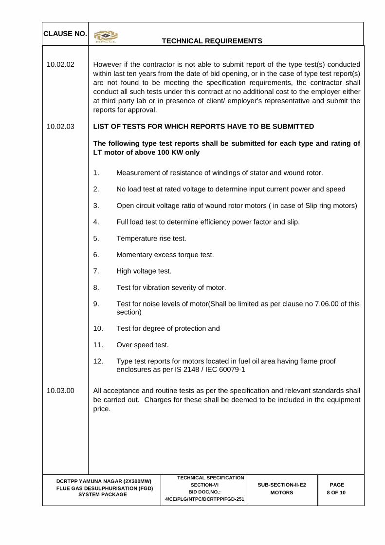
10.02.03 LIST OF TESTS FOR WHICH REPORTS HAVE TO BE SUBMITTED
The following type test reports shall be submitted for each type and rating of LT motor of above 100 KW only 1. Measurement of resistance of windings of stator and wound rotor. 2. No load test at rated voltage to determine input current power and speed
3. Open circuit voltage ratio of wound rotor motors ( in case of Slip ring motors) 4. Full load test to determine efficiency power factor and slip. 5. Temperature rise test. 6. Momentary excess torque test. 7. High voltage test.
8. Test for vibration severity of motor. 9. Test for noise levels of motor(Shall be limited as per clause no 7.06.00 of this
section) 10. Test for degree of protection and 11. Over speed test. 12. Type test reports for motors located in fuel oil area having flame proof
enclosures as per IS 2148 / IEC 60079-1
10.03.00 All acceptance and routine tests as per the specification and relevant standards shall be carried out. Charges for these shall be deemed to be included in the equipment price.
CLAUSE NO.
TECHNICAL REQUIREMENTS
DCRTPP YAMUNA NAGAR (2X300MW) FLUE GAS DESULPHURISATION (FGD)
SYSTEM PACKAGE
TECHNICAL SPECIFICATION SECTION-VI
BID DOC.NO.: 4/CE/PLG/NTPC/DCRTPP/FGD-251
SUB-SECTION-II-E2 MOTORS
PAGE 9 OF 10
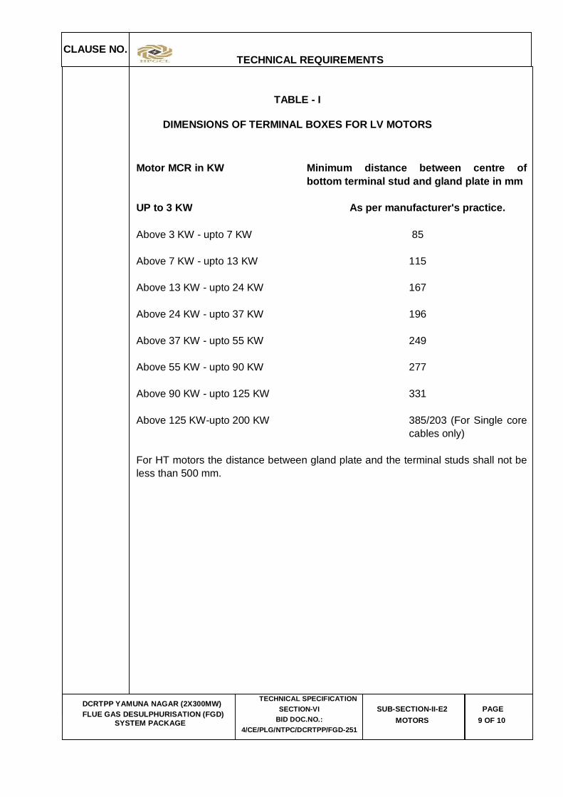
TABLE - I
DIMENSIONS OF TERMINAL BOXES FOR LV MOTORS
Motor MCR in KW Minimum distance between centre of bottom terminal stud and gland plate in mm
UP to 3 KW As per manufacturer's practice. Above 3 KW - upto 7 KW 85 Above 7 KW - upto 13 KW 115 Above 13 KW - upto 24 KW 167 Above 24 KW - upto 37 KW 196 Above 37 KW - upto 55 KW 249 Above 55 KW - upto 90 KW 277 Above 90 KW - upto 125 KW 331 Above 125 KW-upto 200 KW 385/203 (For Single core
cables only) For HT motors the distance between gland plate and the terminal studs shall not be
less than 500 mm.

CLAUSE NO.
TECHNICAL REQUIREMENTS
DCRTPP YAMUNA NAGAR (2X300MW) FLUE GAS DESULPHURISATION (FGD)
SYSTEM PACKAGE
TECHNICAL SPECIFICATION SECTION-VI
BID DOC.NO.: 4/CE/PLG/NTPC/DCRTPP/FGD-251
SUB-SECTION-II-E2 MOTORS
PAGE 10 OF 10
PHASE TO PHASE/ PHASE TO EARTH AIR CLEARANCE:
Minimum inter-phase and phase-earth air clearances for LT motors with lugs installed shall be as follows:
Motor MCR in KW Clearance UP to 110 KW 10mm Above 110 KW and up to 150 KW 12.5mm Above 150 KW 19mm
DCRTPP YAMUNA NAGAR (2X300 MW) FLUE GAS DESULPHURISATION (FGD)
SYSTEM PACKAGE
TECHNICAL SPECIFICATION SECTION-VI
BID DOCUMENT NO.: 4/CE/PLG/NTPC/DCRTPP/FGD-251
SUB-SECTION-II-E3
MEDIUM VOLTAGE BUS DUCTS
CLAUSE NO.
TECHNICAL REQUIREMENTS
DCRTPP YAMUNA NAGAR (2X300MW) FLUE GAS DESULPHURISATION (FGD)
SYSTEM PACKAGE
TECHNICAL SPECIFICATION
SECTION-VI, PART-B BID DOC. NO.:
4/CE/PLG/NTPC/DCRTPP/FGD-251
SUB SECTION-II-E3 Medium Voltage Busducts
PAGE 1 OF 9
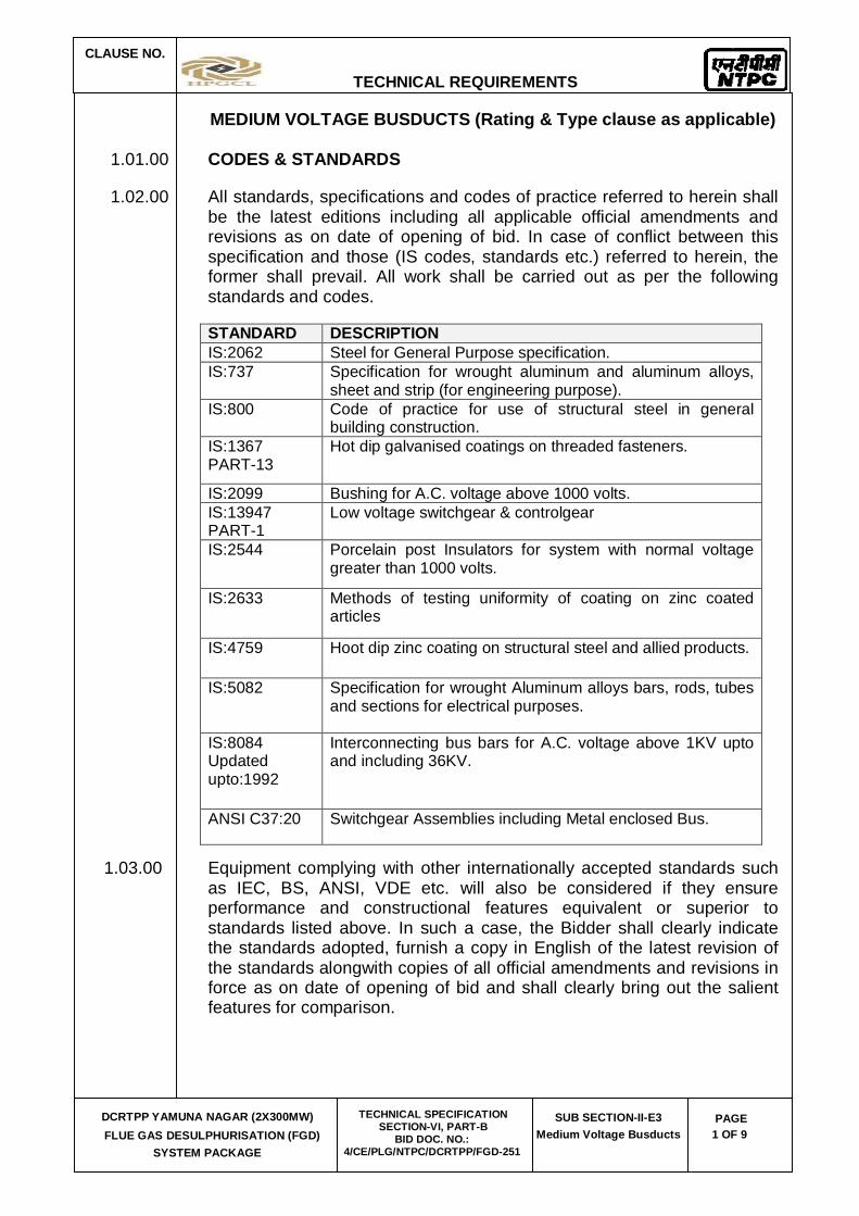
MEDIUM VOLTAGE BUSDUCTS (Rating & Type clause as applicable)
1.01.00 CODES & STANDARDS
1.02.00 All standards, specifications and codes of practice referred to herein shall be the latest editions including all applicable official amendments and revisions as on date of opening of bid. In case of conflict between this specification and those (IS codes, standards etc.) referred to herein, the former shall prevail. All work shall be carried out as per the following standards and codes.
STANDARD DESCRIPTION IS:2062 Steel for General Purpose specification. IS:737 Specification for wrought aluminum and aluminum alloys,
sheet and strip (for engineering purpose). IS:800 Code of practice for use of structural steel in general
building construction. IS:1367 PART-13
Hot dip galvanised coatings on threaded fasteners.
IS:2099 Bushing for A.C. voltage above 1000 volts. IS:13947 PART-1
Low voltage switchgear & controlgear
IS:2544 Porcelain post Insulators for system with normal voltage greater than 1000 volts.
IS:2633 Methods of testing uniformity of coating on zinc coated articles
IS:4759 Hoot dip zinc coating on structural steel and allied products.
IS:5082 Specification for wrought Aluminum alloys bars, rods, tubes and sections for electrical purposes.
IS:8084 Updated upto:1992
Interconnecting bus bars for A.C. voltage above 1KV upto and including 36KV.
ANSI C37:20 Switchgear Assemblies including Metal enclosed Bus.
1.03.00 Equipment complying with other internationally accepted standards such as IEC, BS, ANSI, VDE etc. will also be considered if they ensure performance and constructional features equivalent or superior to standards listed above. In such a case, the Bidder shall clearly indicate the standards adopted, furnish a copy in English of the latest revision of the standards alongwith copies of all official amendments and revisions in force as on date of opening of bid and shall clearly bring out the salient features for comparison.

CLAUSE NO.
TECHNICAL REQUIREMENTS
DCRTPP YAMUNA NAGAR (2X300MW) FLUE GAS DESULPHURISATION (FGD)
SYSTEM PACKAGE
TECHNICAL SPECIFICATION
SECTION-VI, PART-B BID DOC. NO.:
4/CE/PLG/NTPC/DCRTPP/FGD-251
SUB SECTION-II-E3 Medium Voltage Busducts
PAGE 2 OF 9
1.04.00 Installation work shall also conform to Indian Electricity Act and Indian Electricity Rules as amended upto date.
2.00.00 GENERAL TECHNICAL REQUIREMENTS
2.01.00 The busduct will serve as interconnections between transformers and switchgears, and between switchgears. The technical parameters of busduct (11KV, 6.6 KV & 3.3 KV) are enclosed at Annexure-A to this section.
2.02.00 The busduct will be installed partially indoors and partially outdoors in a hot, humid and tropical atmosphere.
2.03.00 The maximum temperature of the bus conductor and enclosure shall be as defined in the technical parameters when operating at maximum ambient temperature and carrying rated current continuously. For outdoor portions the effect of solar radiation shall also be considered. The bidder shall furnish calculation for temperature rise taking effect of solar radiation into consideration.
2.04.00 The busduct shall be capable of withstanding the mechanical forces and thermal effects of three phase short circuit currents, mentioned in the technical parameters at ANNEXURE-A, without any damage, deformation or deterioration of material.
3.00.00 EQUIPMENT DESCRIPTION
3.01.00 Bus Conductor
3.01.01 The bus conductor shall be of high conductivity aluminum alloy, adequately supported on insulators to withstand dynamic stress due to the specified short circuit current, without permanent deformation.
3.01.02 Flexible joints shall be provided between busduct sections to take care of expansion and contraction, wherever deemed necessary by the Bidder, for temperature variations between 0 Deg. C. and that achieved during a short circuit after full load operation at 50 Deg. C. ambient. Flexible connection shall also be provided for termination at each transformer and switchgear end. Details of transformer bushings and switchgear terminals for owners scope (if any) shall be intimated to the successful bidder during the detailed engineering stage. Clearances provided by removable connections shall be adequate for independently testing the equipment being connected by these.
CLAUSE NO.
TECHNICAL REQUIREMENTS
DCRTPP YAMUNA NAGAR (2X300MW) FLUE GAS DESULPHURISATION (FGD)
SYSTEM PACKAGE
TECHNICAL SPECIFICATION
SECTION-VI, PART-B BID DOC. NO.:
4/CE/PLG/NTPC/DCRTPP/FGD-251
SUB SECTION-II-E3 Medium Voltage Busducts
PAGE 3 OF 9
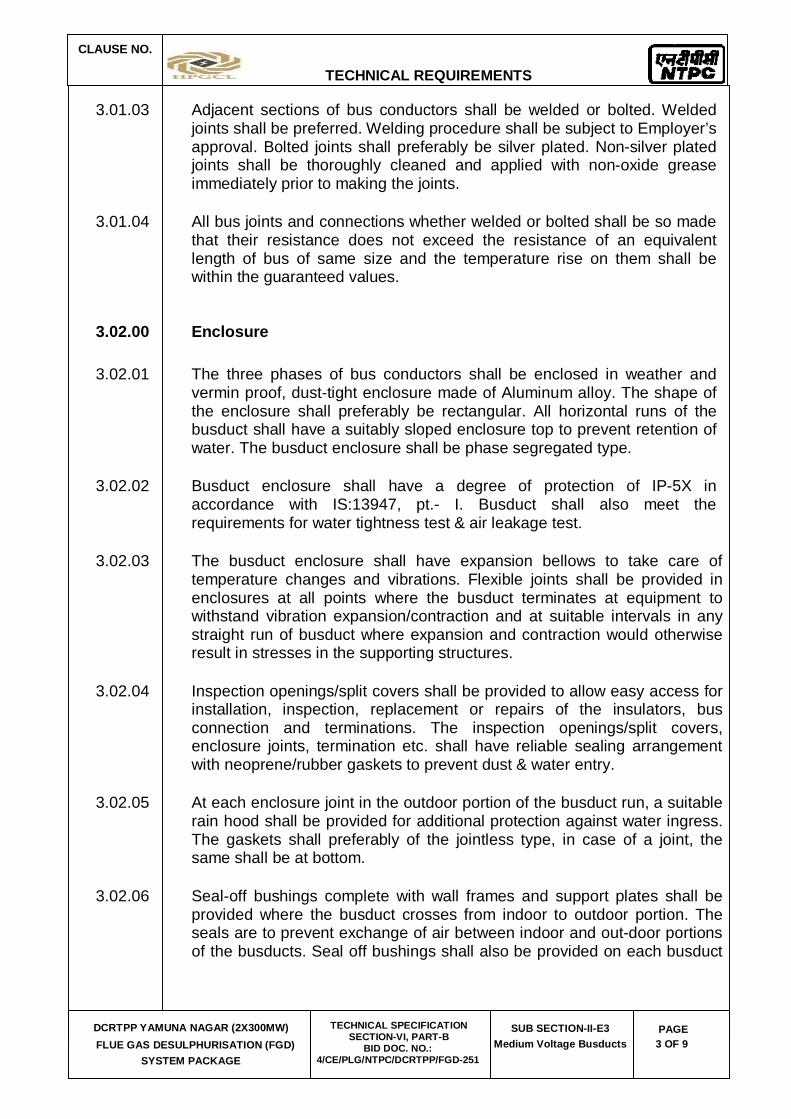
3.01.03 Adjacent sections of bus conductors shall be welded or bolted. Welded joints shall be preferred. Welding procedure shall be subject to Employer’s approval. Bolted joints shall preferably be silver plated. Non-silver plated joints shall be thoroughly cleaned and applied with non-oxide grease immediately prior to making the joints.
3.01.04 All bus joints and connections whether welded or bolted shall be so made that their resistance does not exceed the resistance of an equivalent length of bus of same size and the temperature rise on them shall be within the guaranteed values.
3.02.00 Enclosure
3.02.01 The three phases of bus conductors shall be enclosed in weather and vermin proof, dust-tight enclosure made of Aluminum alloy. The shape of the enclosure shall preferably be rectangular. All horizontal runs of the busduct shall have a suitably sloped enclosure top to prevent retention of water. The busduct enclosure shall be phase segregated type.
3.02.02 Busduct enclosure shall have a degree of protection of IP-5X in accordance with IS:13947, pt.- I. Busduct shall also meet the requirements for water tightness test & air leakage test.
3.02.03 The busduct enclosure shall have expansion bellows to take care of temperature changes and vibrations. Flexible joints shall be provided in enclosures at all points where the busduct terminates at equipment to withstand vibration expansion/contraction and at suitable intervals in any straight run of busduct where expansion and contraction would otherwise result in stresses in the supporting structures.
3.02.04 Inspection openings/split covers shall be provided to allow easy access for installation, inspection, replacement or repairs of the insulators, bus connection and terminations. The inspection openings/split covers, enclosure joints, termination etc. shall have reliable sealing arrangement with neoprene/rubber gaskets to prevent dust & water entry.
3.02.05 At each enclosure joint in the outdoor portion of the busduct run, a suitable rain hood shall be provided for additional protection against water ingress. The gaskets shall preferably of the jointless type, in case of a joint, the same shall be at bottom.
3.02.06 Seal-off bushings complete with wall frames and support plates shall be provided where the busduct crosses from indoor to outdoor portion. The seals are to prevent exchange of air between indoor and out-door portions of the busducts. Seal off bushings shall also be provided on each busduct

CLAUSE NO.
TECHNICAL REQUIREMENTS
DCRTPP YAMUNA NAGAR (2X300MW) FLUE GAS DESULPHURISATION (FGD)
SYSTEM PACKAGE
TECHNICAL SPECIFICATION
SECTION-VI, PART-B BID DOC. NO.:
4/CE/PLG/NTPC/DCRTPP/FGD-251
SUB SECTION-II-E3 Medium Voltage Busducts
PAGE 4 OF 9
termination on a switchgear. Where busduct cross building internal wall only wall frame assemblies shall be provided.
3.02.07 The busduct enclosure shall be adequately rigid and stiffeners shall be provided wherever necessary. Minimum enclosure thickness shall be 3 mm.
3.02.08 Phase barriers made of aluminum alloy shall be provided in the busduct for phase segregation. Minimum thickness shall be 3 mm.
3.02.09 Opening covered with louvers backed up with removable dust filters and silica gel breather shall be provided at indoor & outdoor potion of busduct to enable the busduct enclosure to breathe in a manner so that possibility of condensation and ingress of dust is minimised.
3.02.10 Filtered drain plugs for drainage of condensate and seepage water if any shall be provided at the lowest points and at such location where accumulation of condensate can be expected. These drain plugs shall be located at a suitable place convenient to operate.
3.03.00 Insulators
3.03.01 Bus support insulators shall be interchangeable, high creep, high strength and made of fine glazed solid porcelain manufactured by wet process or high strength cast resin insulators.
3.03.02 The insulators shall be designed and mounted in such a manner so as to facilitate easy inspection, removal and replacement without disturbing the conductor.
3.03.03 The conductors shall be fixed to the insulator so to permit differential expansion and contraction with the enclosure without overstressing the insulators. The insulators shall be designed to safely withstand the maximum possible short circuit forces.
3.03.04 All bolts, nuts and lock washers used in the bus assembly shall be high tensile steel, plated for corrosion resistance. Spring washers or equivalent means shall be used for ensuring good contact pressure under all operating conditions. All bolts shall be tightened using properly calibrated torque spanner by applying the recommended torque.
3.04.00 Space Heaters
3.04.01 The busduct shall be provided with adequate number of thermostatically controlled space heaters of adequate capacity to maintain the internal

CLAUSE NO.
TECHNICAL REQUIREMENTS
DCRTPP YAMUNA NAGAR (2X300MW) FLUE GAS DESULPHURISATION (FGD)
SYSTEM PACKAGE
TECHNICAL SPECIFICATION
SECTION-VI, PART-B BID DOC. NO.:
4/CE/PLG/NTPC/DCRTPP/FGD-251
SUB SECTION-II-E3 Medium Voltage Busducts
PAGE 5 OF 9
temperature above the dew point to prevent moisture condensation within the busduct. Space heaters shall be rated for 240V, single phase, 50Hz AC supply.
3.04.02 The space heaters and thermostats shall be wired upto terminals in suitably located terminal boxes to be provided by the contractor. The space heater wiring inside the busduct enclosure shall be done with high temperature resistant cables as the ambient temperature existing inside the busduct enclosure may vary from 80 deg.C to 90 deg.C. The minimum conductor size of space heater wiring shall be 2.5 sq.mm. A separate ON/OFF switch shall be provided for controlling the space heaters of each busduct in the marshalling box located at convenient height. One number single phase 240V power supply at the marshalling box for complete run of every busduct shall be provided by employer. All cabling between space heaters/thermostats and marshalling box in the run of busduct shall be supplied and erected by the contractor. Cable entry points to the busduct shall be sealed properly by providing suitable glands.
3.05.00 Busduct Support
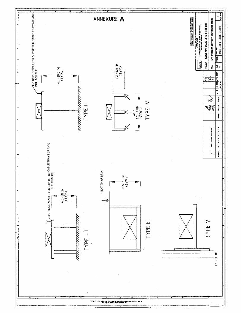
3.05.01 Bidder shall provided necessary support structures and all hardware structures to support the busduct all along its route.
3.05.02 The design of the support structure shall conform to IS:800. Suitable members shall be provided along the outdoor support structure for supporting cable trays (if any).
3.05.03 In the indoor portions, the busduct shall be supported from floor / roof beams or steel inserts in upper floors. In the outdoor potions, they shall be supported from the ground, by means of steel structures, unless indicated otherwise in the specification drawings.
3.05.04 All steel structures required for busduct support shall be hot dip galvanised and shall be strong enough to cater for various static and dynamic loading such as weight of busduct, short circuit forces, wind load, thermal expansion and contraction etc.
3.05.05 All hardware shall be galvanised or cadmium plated.
3.06.00 Earthing
3.06.01 Adequately sized galvanised mild steel or aluminium earth bar shall be provided along the entire run of each busduct. Each section of the busduct enclosure shall be bonded to this earth bar at least at both ends

CLAUSE NO.
TECHNICAL REQUIREMENTS
DCRTPP YAMUNA NAGAR (2X300MW) FLUE GAS DESULPHURISATION (FGD)
SYSTEM PACKAGE
TECHNICAL SPECIFICATION
SECTION-VI, PART-B BID DOC. NO.:
4/CE/PLG/NTPC/DCRTPP/FGD-251
SUB SECTION-II-E3 Medium Voltage Busducts
PAGE 6 OF 9
of the enclosure. The earth bar shall be connected to the main earthing system at its two ends by the contractor.
3.07.00 Connection and Termination
3.07.01 All matching flanges, flexible connections, adopter boxes, gaskets, fittings, hardware and support required for termination of the busduct at transformer and switchgear ends, shall be provided by the Bidder.
3.08.00 The bidder shall co-ordinate, through the Employer/Project Manager, with the suppliers of the transformers and switchgears (if any), regarding the termination details.
3.08.01 Flexible connections at equipment termination shall be able to take care of misalignment upto 25 mm in all directions.
3.08.02 The equipment terminal connections shall be easily accessible and shall provide sufficient air gap for safe isolation of equipment during testing.
3.08.03 All hardware used in the MV Busduct shall be non-magnetic.
3.08.04 Suitable bi-metallic connectors shall be provided wherever the material of bus conductor and equipment terminals are different.
3.09.00 Paint and Finish
3.09.01 All surfaces shall be thoroughly cleaned and cleared of all blemishes. De-rusting, degreasing etc. shall be done before painting or galvanising. Paints shall be carefully selected to withstand heat and weather conditions. The paints shall not scale off or crinkle or get removed by abrasion due to normal handling.
3.09.02 The paints shall consist of one coat of primer followed by one anti-corrosive coat for steel structures. Finally two coast of finishing paint shall be given. The final colour shade shall be BLUE RAL: 5012.
3.09.03 The bus conductor and the inside surface of the enclosure shall be treated with matt black paint for efficient heat dissipation.
3.09.04 Sufficient quantity of all paints required for touching up at site, shall be provided.

CLAUSE NO.
TECHNICAL REQUIREMENTS
DCRTPP YAMUNA NAGAR (2X300MW) FLUE GAS DESULPHURISATION (FGD)
SYSTEM PACKAGE
TECHNICAL SPECIFICATION
SECTION-VI, PART-B BID DOC. NO.:
4/CE/PLG/NTPC/DCRTPP/FGD-251
SUB SECTION-II-E3 Medium Voltage Busducts
PAGE 7 OF 9
4.00.00 TYPE & ROUTINE TESTS
4.01.01 All equipments to be supplied shall be of type tested design. During
detailed engineering, the contractor shall submit for Employer’s approval the reports of all the type tests as listed in this specification and carried out within last ten years from the date of bid opening. These reports should be for the test conducted on the equipment similar to those proposed to be supplied under this contract and the test(s) should have been either conducted at an independent laboratory or should have been witnessed by a client.
4.01.02 However if the contractor is not able to submit report of the type test(s)
conducted within last ten years from the date of bid opening, or in the case of type test report(s) are not found to be meeting the specification requirements, the contractor shall conduct all such tests under this contract at no additional cost to the Employer either at third party lab or in presence of client /Employers representative and submit the reports for approval.
4.01.03 All acceptance and routine tests as per the specification and relevant
standards shall be carried out. Charges for these shall be deemed to be included in the equipment price.
4.01.04 LIST OF TYPE TESTS
4.01.01 Medium voltage Busduct
The following type tests reports to be submitted on each rating of bus ducts:
(a.) Heat run test (the set up shall include 3 phase straight run, 90 deg. bend, set of flexible connection of each type, and necessary inspection covers).
(b.) Short circuit withstand test (set up same as for heat run).
(c.) Impulse withstand test (set up shall include typical X-section with flexible connections, 90 degree bend, seal off bushing and inspection cover.
(d.) Air leakage rate and Water tightness test (set up shall include inspection cover, flanged joint and bellow).
4.02.00 ROUTINE TESTS
Routine tests shall be conducted at manufactures works on each busduct and all other components as per relevant Indian Standards & Quality Assurance Sub-section.

CLAUSE NO.
TECHNICAL REQUIREMENTS
DCRTPP YAMUNA NAGAR (2X300MW) FLUE GAS DESULPHURISATION (FGD)
SYSTEM PACKAGE
TECHNICAL SPECIFICATION
SECTION-VI, PART-B BID DOC. NO.:
4/CE/PLG/NTPC/DCRTPP/FGD-251
SUB SECTION-II-E3 Medium Voltage Busducts
PAGE 8 OF 9
ANNEXURE-A
S.No. PARAMETER 11KV BUSDUCT
6.6KV BUSDUCT
3.3KV BUSDUCT
(1.) Number of phase 3 3 3
(2.) Frequency 50 Hz 50 Hz 50 Hz
(3.) Nominal voltage 11KV 6.6KV 3.3 KV
(4.) Highest system voltage 12KV 7.2KV 3.6 KV
(5.) One minute power Frequency Withstand voltage (Dry & wet)
35KV 27KV 21KV
(6.) Impulse voltage withstand value with 1.2/50 microsecond wave shape
75KV 60KV 40 KV
(7.) Continuous current rating at 500C ambient
As per system requirement
As per system requirement
As per system requirement.
(8.) Short time current rating for 1 second
40KA (rms)
40KA (rms)
40KA (rms)
(9.) Dynamic current withstand rating. 100 KA(peak)
(10.) Type of Cooling Natural
(11.) Type of Bus enclosure Phase segregated
(12.) Service Indoor/Outdoor
(13.) Minimum clearance of live parts in Air
Shall be as per type tested set up piece
a)Phase to phase -do-
b)Phase to earth -do-
(14.) Busbar Material Aluminum alloy
(15.) Enclosure & Partition Material Aluminum alloy
(16.) Minimum thickness of enclosure 3 mm

CLAUSE NO.
TECHNICAL REQUIREMENTS
DCRTPP YAMUNA NAGAR (2X300MW) FLUE GAS DESULPHURISATION (FGD)
SYSTEM PACKAGE
TECHNICAL SPECIFICATION
SECTION-VI, PART-B BID DOC. NO.:
4/CE/PLG/NTPC/DCRTPP/FGD-251
SUB SECTION-II-E3 Medium Voltage Busducts
PAGE 9 OF 9
S.No. PARAMETER 11KV BUSDUCT
6.6KV BUSDUCT
3.3KV BUSDUCT
(17.) Minimum thickness of partition 3 mm
(18.) Insulators & bushings
a) Rated Voltage 12 KV 7.2KV 3.6 KV
b) One min power frequency withstand Voltage
(i) Dry 35 KV (rms)
27KV (rms)
21KV(rms)
(ii) Wet 35 KV (rms)
27KV (rms)
21KV(rms)
c) Impulse Voltage withstand Value with 1.2/50 micro sec wave shape.
75 KV 60KV 40KV
d) Minimum Creepage Distance 240 mm 180KV 130 mm
e) Material of Insulator/Bushing Porcelain/Cast Resin
(19.) Material of earthing conductor Galvanized mild steel/ Aluminium
(20.) Design ambient Temperature 50°C
(21.) Maximum temperature rise over an ambient of 500C when carrying the rated current continuously ( with effect of solar radiation)
a) Bus Conductor
For Indoor Portion
For Outdoor Portion
(i)Bolted Joints (Plainor tinned) 40°C 32.5°C
(ii)Bolted Joints (silver plated) 55°C 47.5°C
b)Busduct Enclosure 30°C 22.5°C
prm09012
Text Box
.

DCRTPP YAMUNA NAGAR (2X300 MW) FLUE GAS DESULPHURISATION (FGD)
SYSTEM PACKAGE
TECHNICAL SPECIFICATION SECTION-VI
BID DOCUMENT NO.: 4/CE/PLG/NTPC/DCRTPP/FGD-251
SUB-SECTION-II-E4
LT POWER CABLES

CLAUSE NO.
TECHNICAL REQUIREMENTS
DCRTPP YAMUNA NAGAR (2X300MW) FLUE GAS DESULPHURISATION (FGD)
SYSTEM PACKAGE
TECHNICAL SPECIFICATION SECTION-VI, PART-B
BID DOC. NO.: 4/CE/PLG/NTPC/DCRTPP/FGD-251
SUB SECTION-II-E4 LT POWER CABLES
PAGE 1 OF 6
1.00.00 CODES & STANDARDS
1.01.00 All standards, specifications and codes of practice referred to herein shall be the latest editions including all applicable official amendments and revisions as on date of opening of bid. In case of conflict between this specification and those (IS: codes, standards, etc.) referred to herein, the former shall prevail. All the cables shall conform to the requirements of the following standards and codes:
IS :1554 - I PVC insulated (heavy duty) electric cables for working voltages upto
and including 1100V.
IS : 3961 Recommended current ratings for cables
IS : 3975 Low carbon galvanised steel wires, formed wires and tapes for
armouring of cables.
IS : 5831 PVC insulation and sheath of electrical cables.
IS:7098 (Part -I) Cross linked polyethylene insulated PVC sheathed cables for
working voltages upto and including 1100V.
IS : 8130 Conductors for insulated electrical cables and flexible cords.
IS : 10418 Specification for drums for electric cables.
IS : 10810 Methods of tests for cables.
ASTM-D -2843 Standard test method for density of smoke from the burning or
decomposition of plastics.
IEC-754 (Part-I)
Tests on gases evolved during combustion of electric cables.
IEC-332 Tests on electric cables under fire conditions. Part-3: Tests on bunched wires or cables (Category-B).
2.00.00 TECHNICAL REQUIREMENTS
2.01.00 The cables shall be suitable for laying on racks, in ducts, trenches, conduits and under ground buried installation with chances of flooding by water.

CLAUSE NO.
TECHNICAL REQUIREMENTS
DCRTPP YAMUNA NAGAR (2X300MW) FLUE GAS DESULPHURISATION (FGD)
SYSTEM PACKAGE
TECHNICAL SPECIFICATION SECTION-VI, PART-B
BID DOC. NO.: 4/CE/PLG/NTPC/DCRTPP/FGD-251
SUB SECTION-II-E4 LT POWER CABLES
PAGE 2 OF 6
2.02.00 All cables including EPR cables shall be flame retardant, low smoke (FRLS) type designed to withstand all mechanical, electrical and thermal stresses developed under steady state and transient operating conditions as specified elsewhere in this specification.
2.03.00 Aluminium conductor used in power cables shall have tensile strength of more than 100 N/ sq.mm. Conductors shall be stranded.
2.04.00 XLPE insulation shall be suitable for a continuous conductor temperature of 90 deg. C and short circuit conductor temperature of 250 deg C. PVC insulation shall be suitable for continuous conductor temperature of 70 deg C and short circuit conductor temperature of 160 deg. C.
2.05.00 The cable cores shall be laid up with fillers between the cores wherever necessary. It shall not stick to insulation and inner sheath. All the cables shall have distinct extruded PVC inner sheath of black colour as per IS: 5831.
2.06.00 For single core armoured cables, armouring shall be of aluminium wires/ formed wires. For multicore armoured cables, armouring shall be of galvanised steel as follows :
Calculated nominal dia. of cable under armour
Size and Type of armour
Upto 13 mm
1.4mm dia GS wire
Above 13 & upto 25mm 0.8 mm thick GS formed wire / 1.6 mm dia GS wire
Above 25 & upto 40 mm 0.8mm thick GS formed wire / 2.0mm dia GS wire
Above 40 & upto 55mm 1.4 mm thick GS formed wire /2.5mm dia GS wire
Above 55 & upto 70 mm 1.4mm thick GS formed wire / 3.15mm dia GS wire
Above 70mm 1.4 mm thick GS formed wire / 4.0 mm dia GS wire
2.06.01 The aluminium used for armouring shall be of H4 grade as per IS: 8130 with maximum resistivity of 0.028264 ohm mm2 per meter at 20 deg C. The sizes of aluminium armouring shall be same as indicated above for galvanized steel.
2.06.02 The gap between armour wires / formed wires shall not exceed one armour wire / formed wire space and there shall be no cross over / over-riding of armour wire / formed wire. The minimum area of coverage of armouring shall be 90%. The breaking load of armour joint shall not be less than 95% of that of armour wire / formed wire. Zinc rich paint shall be applied on armour joint surface of G.S.wire/ formed wire.
2.07.00 Outer sheath shall be of PVC as per IS: 5831 & black in colour. In addition to meeting all the requirements of Indian standards referred to, outer sheath of all the cables shall have the following FRLS properties.
(a.) Oxygen index of min. 29 (as per IS 10810 Part-58).
(b.) Acid gas emission of max. 20% (as per IEC-754-I).
(c.) Smoke density rating shall not be more than 60 % (as per ASTMD-2843).

CLAUSE NO.
TECHNICAL REQUIREMENTS
DCRTPP YAMUNA NAGAR (2X300MW) FLUE GAS DESULPHURISATION (FGD)
SYSTEM PACKAGE
TECHNICAL SPECIFICATION SECTION-VI, PART-B
BID DOC. NO.: 4/CE/PLG/NTPC/DCRTPP/FGD-251
SUB SECTION-II-E4 LT POWER CABLES
PAGE 3 OF 6
2.08.00 Cores of the cables shall be identified by colouring of insulation. Following colour scheme shall be adopted:
1 core - Red, Black, Yellow or Blue
2 core - Red & Black
3 core - Red, Yellow & Blue
4 core - Red, Yellow, Blue and Black
2.09.00 For reduced neutral conductors, the core shall be black.
2.10.00 In addition to manufacturer's identification on cables as per IS, following marking shall also be provided over outer sheath.
(a.) Cable size and voltage grade - To be embossed
(b.) Word 'FRLS' at every 5 metre - To be embossed
(c.) Sequential marking of length of the cable in metres at every one metre -To be embossed / printed
The embossing shall be progressive, automatic, in line and marking shall be legible and indelible. For EPR cables identification shall be printed on outer sheath.
2.11.00 All cables shall meet the fire resistance requirement as per Category-B of IEC 332 Part-3.
2.12.00 Allowable tolerances on the overall diameter of the cables shall be +\-2 mm maximum, over the declared value in the technical data sheets.
2.13.00 In plant repairs to the cables shall not be accepted. Pimples, fish eye, blow holes etc. are not acceptable.
2.14.00 Cable selection & sizing 2.14.01 Cables shall be sized based on the following considerations: (a) Rated current of the equipment (b) The voltage drop in the cable, during motor starting condition, shall be limited to 10%
and during full load running condition, shall be limited to 3% of the rated voltage (c) Short circuit withstand capability This will depend on the feeder type. For a fuse protected circuit, cable should be
sized to withstand the letout energy of the fuse. For breaker controlled feeder, cable shall be capable of withstanding the system fault current level for total breaker tripping time inclusive of relay pickup time.
2.14.02 Derating Factors Derating factors for various conditions of installations including the following shall be
considered while selecting the cable sizes:

CLAUSE NO.
TECHNICAL REQUIREMENTS
DCRTPP YAMUNA NAGAR (2X300MW) FLUE GAS DESULPHURISATION (FGD)
SYSTEM PACKAGE
TECHNICAL SPECIFICATION SECTION-VI, PART-B
BID DOC. NO.: 4/CE/PLG/NTPC/DCRTPP/FGD-251
SUB SECTION-II-E4 LT POWER CABLES
PAGE 4 OF 6
a) Variation in ambient temperature for cables laid in air b) Grouping of cables c) Variation in ground temperature and soil resistivity for buried cables. 2.14.03 Cable lengths shall be considered in such a way that straight through cable joints are
avoided. 2.14.04 All Cables shall be armoured type. 2.14.05 All LT power cables of sizes more than 120 sq.mm. shall be XLPE insulated and sizes shall
be 1Cx150, 1Cx300, 1Cx630, 3Cx150 & 3Cx240 sq.mm. However for cable sizes upto 120 sq.mm. both XLPE insulated & PVC insulated LT power cables are acceptable.
2.14.16 Same cable sizes to be used for same type of application & rating of motor i.e if there are
three pumps for one application, all three pumps motor should be provided with same cable sizes.
3.00.00 CONSTRUCTIONAL FEATURES 3.01.00 1.1 KV Grade Power Cables (a) 1.1 KV grade XLPE power cables shall have compacted aluminium conductor, XLPE
insulated, PVC inner-sheathed (as applicable), armoured, PVC outer-sheathed conforming to IS:7098. (Part-I).
(b) 1.1KV grade PVC power cables shall have aluminium conductor (compacted type for
sizes above 10 sq.mm), PVC Insulated, PVC inner sheathed (as applicable) armoured, PVC outer-sheathed conforming to IS:1554 (Part-I).
(c) 1.1 KV grade Trailing cables shall have tinned copper (class 5) conductor, insulated
with heat resistant elastomeric compound based on Ethylene Propyline Rubber (EPR) suitable for withstanding 90 deg.C continuous conductor temperature and 250deg C during short circuit, inner-sheathed with heat resistant elastomeric compound, nylon cord reinforced, outer-sheathed with heat resistant, oil resistant and flame retardant heavy duty elastomeric compound conforming to IS 9968.
4.00.00 CABLE DRUMS
(a) Cables shall be supplied in non returnable wooden or steel drums of heavy construction. The surface of the drum and the outer most cable layer shall be covered with water proof cover. Both the ends of the cables shall be properly sealed with heat shrinkable PVC/ rubber caps secured by 'U' nails so as to eliminate ingress of water during transportation, storage and erection. Wood preservative anti-termite treatment shall be applied to the entire drum. Wooden drums shall comply with IS: 10418.
(b) Each drum shall carry manufacturer's name, purchaser’s name, address and contract number, item number and type, size and length of cable and net gross weight stencilled on both sides of the drum. A tag containing same information shall be attached to the leading end of the cable. An arrow and suitable accompanying wording shall be marked on one end of the reel indicating the direction in which it should be rolled.
(c.) The standard drum length of LT power cable with a maximum tolerance of +/- 5% may be decided by the bidder subject to condition that there shall not be any joint in cable,
CLAUSE NO.
TECHNICAL REQUIREMENTS
DCRTPP YAMUNA NAGAR (2X300MW) FLUE GAS DESULPHURISATION (FGD)
SYSTEM PACKAGE
TECHNICAL SPECIFICATION SECTION-VI, PART-B
BID DOC. NO.: 4/CE/PLG/NTPC/DCRTPP/FGD-251
SUB SECTION-II-E4 LT POWER CABLES
PAGE 5 OF 6
where application length of cable is up to & including 1000 meter for single core cable excluding 630 sq.mm size, and 750 meter for multicore cable & single core 630 sq.mm
5.00.00 TESTS
1.0 All equipments to be supplied shall be of type tested design. During detailed engineering, the contractor shall submit for Employer’s approval the reports of all the type tests as listed in this specification and carried out within last ten years from the date of bid opening. These reports should be for the test conducted on the equipment similar to those proposed to be supplied under this contract and the test(s) should have been either conducted at an independent laboratory or should have been witnessed by a client.
2.0 However if the contractor is not able to submit report of the type test(s) conducted within last ten years from the date of bid opening, or in the case of type test report(s) are not found to be meeting the specification requirements, the contractor shall conduct all such tests under this contract at no additional cost to the Employer either at third party lab or in presence of client /Employers representative and submit the reports for approval.
3.0 All acceptance and routine tests as per the specification and relevant standards shall be carried out. Charges for these shall be deemed to be included in the equipment price.
5.01.00 Type Tests
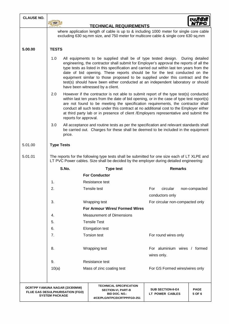
5.01.01 The reports for the following type tests shall be submitted for one size each of LT XLPE and LT PVC Power cables. Size shall be decided by the employer during detailed engineering:
S.No. Type test Remarks
For Conductor 1. Resistance test
2. Tensile test For circular non-compacted
conductors only
3. Wrapping test For circular non-compacted only
For Armour Wires/ Formed Wires
4. Measurement of Dimensions
5. Tensile Test 6. Elongation test
7. Torsion test For round wires only
8. Wrapping test For aluminium wires / formed
wires only.
9. Resistance test
10(a) Mass of zinc coating test For GS Formed wires/wires only

CLAUSE NO.
TECHNICAL REQUIREMENTS
DCRTPP YAMUNA NAGAR (2X300MW) FLUE GAS DESULPHURISATION (FGD)
SYSTEM PACKAGE
TECHNICAL SPECIFICATION SECTION-VI, PART-B
BID DOC. NO.: 4/CE/PLG/NTPC/DCRTPP/FGD-251
SUB SECTION-II-E4 LT POWER CABLES
PAGE 6 OF 6
10(b) Uniformity of zinc coating For GS Formed wires /wires only
11. Adhesion test For GS Formed wires/wires only
For PVC/XLPE insulation & PVC Sheath
12. Test for thickness
13. Tensile strength & elongation tests before ageing and after ageing
14. Ageing in air oven
15. Loss of mass test For PVC insulation and sheath only
16. Hot deformation test For PVC insulation and sheath only
17. Heat shock test For PVC insulation and sheath only
18. Shrinkage test
19. Thermal stability test For PVC insulation and sheath only
20. Hot set test For XLPE insulation only
21. Water absorption test For XLPE insulation only
22. Oxygen index test For outer sheath only
23. Smoke density test For outer sheath only
24. Acid gas generation test For outer sheath only
For completed cables
25. Insulation resistance test (Volume resistivity method)
26. High voltage test
27. Flammability test as per IEC-332 Part-3 (Category-B)
Indicative list of tests/checks, Routine and Acceptance tests shall be as per Quality Assurance & Inspection table of LT power cables enclosed.

DCRTPP YAMUNA NAGAR (2X300 MW) FLUE GAS DESULPHURISATION (FGD)
SYSTEM PACKAGE
TECHNICAL SPECIFICATION SECTION-VI
BID DOCUMENT NO.: 4/CE/PLG/NTPC/DCRTPP/FGD-251
SUB-SECTION-II-E5
LT CONTROL CABLES

CLAUSE NO.
TECHNICAL REQUIREMENTS
DCRTPP YAMUNA NAGAR (2X300MW) FLUE GAS DESULPHURISATION (FGD)
SYSTEM PACKAGE
TECHNICAL SPECIFICATION SECTION-VI, PART-B
BID DOC. NO.: 4/CE/PLG/NTPC/DCRTPP/FGD-251
SUB SECTION-II-E5 LT CONTROL CABLES
PAGE 1 OF 6
1.00.00 CODES & STANDARDS
1.01.00 All standards, specifications and codes of practice referred to herein shall be the latest editions including all applicable official amendments and revisions as on date of opening of bid. In case of conflict between this specification and those (IS: codes, standards, etc.) referred to herein, the former shall prevail. All the cables shall conform to the requirements of the following standards and codes:
IS :1554 - I PVC insulated (heavy duty) electric cables for working voltages upto and including 1100V.
IS : 3961 Recommended current ratings for cables
IS : 3975 Low carbon galvanised steel wires, formed wires and tapes for armouring of cables.
IS : 5831 PVC insulation and sheath of electrical cables.
IS : 8130 Conductors for insulated electrical cables and flexible cords.
IS : 10418 Specification for drums for electric cables.
IS : 10810 Methods of tests for cables.
ASTM-D –2843 Standard test method for density of smoke from the burning or decomposition of plastics.
IEC-754 (Part-I) Tests on gases evolved during combustion of electric cables.
IEC-332 Tests on electric cables under fire conditions. Part-3: Tests on bunched wires or cables (Category-B).
2.00.00 TECHNICAL REQUIREMENTS
2.01.00 The cables shall be suitable for laying on racks, in ducts, trenches, conduits and under ground buried installation with chances of flooding by water.
2.02.00 All cables including EPR cables shall be flame retardant, low smoke (FRLS) type designed to withstand all mechanical, electrical and thermal stresses develop under steady state and transient operating conditions as specified elsewhere in this specification.
2.03.00 Conductor of control cables shall be made of stranded, plain annealed copper.
2.04.00 PVC insulation shall be suitable for continuous conductor temperature of 70 deg C and short circuit conductor temperature of 160 deg. C.
2.05.00 The cable cores shall be laid up with fillers between the cores wherever necessary. It shall not stick to insulation and inner sheath. All the cables shall have distinct extruded PVC inner sheath of black colour as per IS: 5831.

CLAUSE NO.
TECHNICAL REQUIREMENTS
DCRTPP YAMUNA NAGAR (2X300MW) FLUE GAS DESULPHURISATION (FGD)
SYSTEM PACKAGE
TECHNICAL SPECIFICATION SECTION-VI, PART-B
BID DOC. NO.: 4/CE/PLG/NTPC/DCRTPP/FGD-251
SUB SECTION-II-E5 LT CONTROL CABLES
PAGE 2 OF 6
2.06.00 For multicore armoured cables, the armouring shall be of galvanised steel as follows:
Calculated nominal dia of cable under armour
Size and Type of armour
Upto 13 mm 1.4mm dia GS wire
Above 13 upto 25 mm 0.8 mm thick GS formed wire / 1.6 mm dia GS wire
Above 25 upto 40 mm 0.8mm thick GS formed wire / 2.0mm dia GS wire
Above 40 upto 55mm 1.4 mm thick GS formed wire/2.5mm dia GS wire
Above 55 upto 70 mm 1.4mm thick GS formed wire / 3.15mm dia GS wire
Above 70mm 1.4 mm thick GS formed wire / 4.0 mm dia GS wire
The gap between armour wires / formed wires shall not exceed one armour wire / formed wire space and there shall be no cross over / over-riding of armour wire / formed wire. The minimum area of coverage of armouring shall be 90%. The breaking load of armour joint shall not be less than 95% of that of armour wire / formed wire. Zinc rich paint shall be applied on armour joint surface.
2.07.00 Outer sheath shall be of PVC as per IS: 5831 and grey in colour. In addition to meeting all the requirements of Indian Standards referred to, outer sheath of all the cables shall have the following FRLS properties.
(a.) Oxygen index of min. 29. (As per IS 10810 Part-58)
(b.) Acid gas emission of max. 20% (As per IEC-754-I)
(c.) Smoke density rating shall not be more than 60% during Smoke Density Test as per ASTMD-2843.
2.08.00 Cores of the cables of upto 5 cores shall be identified by colouring of insulation. Following colour scheme shall be adopted.
1 core - Red, Black, Yellow or Blue
2 core - Red & Black
3 core - Red, Yellow & Blue
4 core - Red, Yellow, Blue and Black
5 core - Red, Yellow, Blue, Black and Grey
2.09.00 For cables having more than 5 cores, core identification shall be done by numbering the insulation of cores sequentially, starting by number 1 in the inner layer (e.g. say for 10 core cable, core numbering shall be from 1 to 10). The number shall be printed in Hindu-Arabic numerals on the outer surfaces of the cores. All the numbers shall be of the same colour, which shall contrast with the colour of insulation. The colour of insulation for all the cores shall be grey only. The numerals shall be legible and indelible. The numbers shall
CLAUSE NO.
TECHNICAL REQUIREMENTS
DCRTPP YAMUNA NAGAR (2X300MW) FLUE GAS DESULPHURISATION (FGD)
SYSTEM PACKAGE
TECHNICAL SPECIFICATION SECTION-VI, PART-B
BID DOC. NO.: 4/CE/PLG/NTPC/DCRTPP/FGD-251
SUB SECTION-II-E5 LT CONTROL CABLES
PAGE 3 OF 6
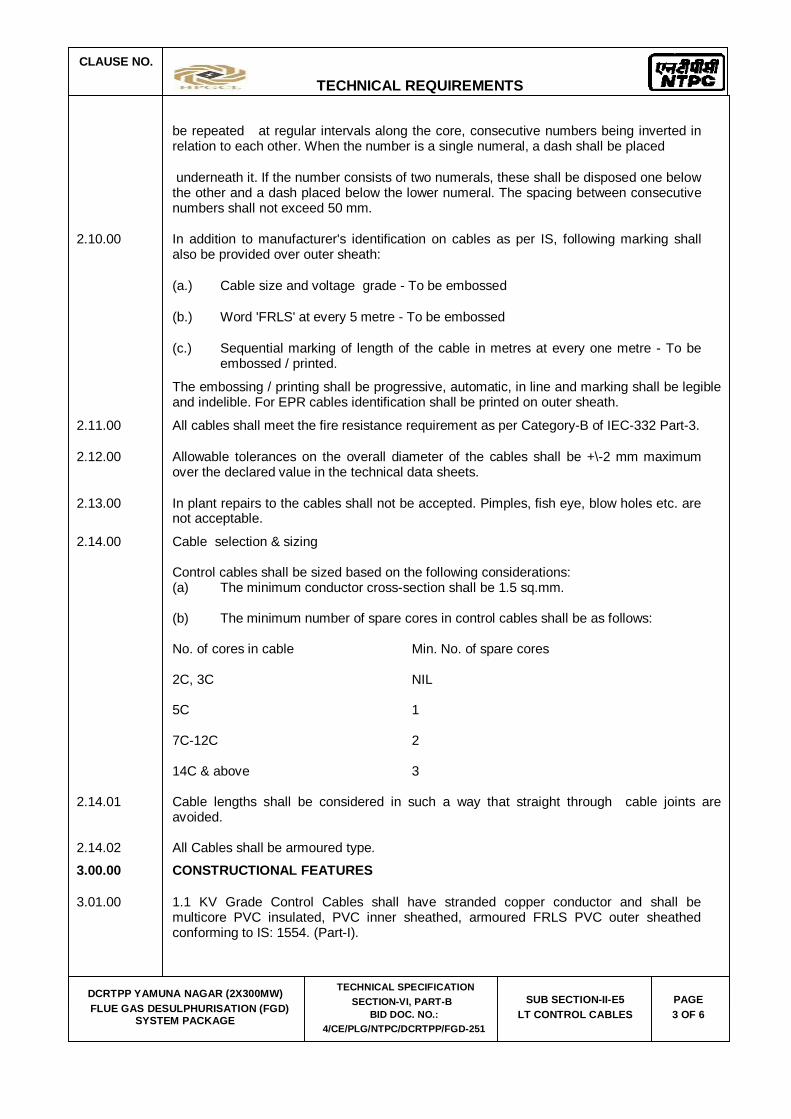
be repeated at regular intervals along the core, consecutive numbers being inverted in relation to each other. When the number is a single numeral, a dash shall be placed
underneath it. If the number consists of two numerals, these shall be disposed one below the other and a dash placed below the lower numeral. The spacing between consecutive numbers shall not exceed 50 mm.
2.10.00 In addition to manufacturer's identification on cables as per IS, following marking shall also be provided over outer sheath:
(a.) Cable size and voltage grade - To be embossed
(b.) Word 'FRLS' at every 5 metre - To be embossed
(c.) Sequential marking of length of the cable in metres at every one metre - To be embossed / printed.
The embossing / printing shall be progressive, automatic, in line and marking shall be legible and indelible. For EPR cables identification shall be printed on outer sheath.
2.11.00 All cables shall meet the fire resistance requirement as per Category-B of IEC-332 Part-3.
2.12.00 Allowable tolerances on the overall diameter of the cables shall be +\-2 mm maximum over the declared value in the technical data sheets.
2.13.00 In plant repairs to the cables shall not be accepted. Pimples, fish eye, blow holes etc. are not acceptable.
2.14.00 Cable selection & sizing Control cables shall be sized based on the following considerations: (a) The minimum conductor cross-section shall be 1.5 sq.mm. (b) The minimum number of spare cores in control cables shall be as follows: No. of cores in cable Min. No. of spare cores 2C, 3C NIL 5C 1 7C-12C 2 14C & above 3 2.14.01 Cable lengths shall be considered in such a way that straight through cable joints are
avoided. 2.14.02 All Cables shall be armoured type. 3.00.00 CONSTRUCTIONAL FEATURES
3.01.00 1.1 KV Grade Control Cables shall have stranded copper conductor and shall be multicore PVC insulated, PVC inner sheathed, armoured FRLS PVC outer sheathed conforming to IS: 1554. (Part-I).
CLAUSE NO.
TECHNICAL REQUIREMENTS
DCRTPP YAMUNA NAGAR (2X300MW) FLUE GAS DESULPHURISATION (FGD)
SYSTEM PACKAGE
TECHNICAL SPECIFICATION SECTION-VI, PART-B
BID DOC. NO.: 4/CE/PLG/NTPC/DCRTPP/FGD-251
SUB SECTION-II-E5 LT CONTROL CABLES
PAGE 4 OF 6
3.02.00 1.1 KV grade Trailing control cables shall have tinned copper (class 5)conductor, insulated with heat resistant elastomeric compound based on Ethylene Propyline Rubber(EPR) suitable for withstanding 90 deg.C continuous conductor temperature and 250deg C during short circuit, inner-sheathed with heat resistant elastomeric compound, nylon cord reinforced, outer-sheathed with heat resistant, oil resistant and flame retardant heavy duty elastomeric compound conforming to IS 9968. Minimum conductor size shall be 2.5 sqmm.
4.00.00 CABLE DRUMS
(a.) Cables shall be supplied in non returnable wooden or steel drums of heavy construction. The surface of the drum and the outer most cable layer shall be covered with water proof cover. Both the ends of the cables shall be properly sealed with heat shrinkable PVC/ rubber caps secured by 'U' nails so as to eliminate ingress of water during transportation, storage and erection. Wood preservative anti-termite treatment shall be applied to the entire drum. Wooden drums shall comply with IS: 10418.
(b.) Each drum shall carry manufacturer's name, purchaser’s name, address and contract number, item number and type, size and length of cable and net gross weight stenciled on both the sides of the drum. A tag containing same information shall be attached to the leading end of the cable. An arrow and suitable accompanying wording shall be marked on one end of the reel indicating the direction in which it should be rolled.
(c.) The standard drum length for control cables with a maximum tolerance of +/- 5% may be decided by the bidder subject to condition that there shall not be any joint in cable, where application length of cable is up to & including 1000 meter.
5.00.00 TESTS
All equipments to be supplied shall be of type tested design. During detailed engineering, the contractor shall submit for Employer’s approval the reports of all the type tests as listed in this specification and carried out within last ten years from the date of bid opening. These reports should be for the test conducted on the equipment similar to those proposed to be supplied under this contract and the test(s) should have been either conducted at an independent laboratory or should have been witnessed by a client.
However if the contractor is not able to submit report of the type test(s) conducted within last ten years from the date of bid opening, or in the case of type test report(s) are not found to be meeting the specification requirements, the contractor shall conduct all such tests under this contract at no additional cost to the Employer either at third party lab or in presence of client /Employers representative and submit the reports for approval.
All acceptance and routine tests as per the specification and relevant standards shall be carried out. Charges for these shall be deemed to be included in the equipment price
5.01.00 TYPE TESTS
5.01.01 The reports for the following type tests shall be submitted for one size of control cables. Size shall be decided by the employer during detailed engineering

CLAUSE NO.
TECHNICAL REQUIREMENTS
DCRTPP YAMUNA NAGAR (2X300MW) FLUE GAS DESULPHURISATION (FGD)
SYSTEM PACKAGE
TECHNICAL SPECIFICATION SECTION-VI, PART-B
BID DOC. NO.: 4/CE/PLG/NTPC/DCRTPP/FGD-251
SUB SECTION-II-E5 LT CONTROL CABLES
PAGE 5 OF 6
S. No. Type Test Remarks
For Conductor
1. Resistance test
For Armour Wires / Formed Wires (If applicable)
2. Measurement of Dimensions
3. Tensile Test
4. Elongation test
5. Torsion test For round wire only
6. Wrapping test For aluminium wires / formed wires only.
7. Resistance test
8(a). Mass of zinc Coating test For GS wires/formed wires only
8(b). Uniformity of zinc coating For GS wires/formed wires only
9. Adhesion test For GS wires/formed wires only
For PVC insulation & PVC Sheath
10. Test for thickness
11. Tensile strength and elongation test
before ageing and after ageing
12. Ageing in air oven
13. Loss of mass test For PVC insulation and sheath only
14. Hot deformation test For PVC insulation and sheath only
15. Heat shock test For PVC insulation and sheath only
16. Shrinkage test

CLAUSE NO.
TECHNICAL REQUIREMENTS
DCRTPP YAMUNA NAGAR (2X300MW) FLUE GAS DESULPHURISATION (FGD)
SYSTEM PACKAGE
TECHNICAL SPECIFICATION SECTION-VI, PART-B
BID DOC. NO.: 4/CE/PLG/NTPC/DCRTPP/FGD-251
SUB SECTION-II-E5 LT CONTROL CABLES
PAGE 6 OF 6
S. No. Type Test Remarks
17. Thermal stability test For PVC insulation and sheath only
18. Oxygen index test For outer sheath only
19. Smoke density test For outer sheath only
20. Acid gas generation test For outer sheath only
For completed cables
21. Insulation resistance test(Volume resistivity method)
22. High voltage test
23. Flammability test as per IEC-332 Part-3 (Category-B)
5.02.00 Indicative list of tests/checks, Routine and Acceptance tests shall be as per Quality
Assurance & Inspection table of Control Cables enclosed.

DCRTPP YAMUNA NAGAR (2X300 MW) FLUE GAS DESULPHURISATION (FGD)
SYSTEM PACKAGE
TECHNICAL SPECIFICATION SECTION-VI
BID DOCUMENT NO.: 4/CE/PLG/NTPC/DCRTPP/FGD-251
SUB-SECTION-II-E6
CABLING EARTHING & LIGHTNING PROTECTION

CLAUSE NO.
TECHNICAL REQUIREMENTS
DCRTPP YAMUNA NAGAR (2X300MW)
FLUE GAS DESULPHURISATION (FGD) SYSTEM PACKAGE
TECHNICAL SPECIFICATION SECTION-VI, PART-B
BID DOC. NO.: 4/CE/PLG/NTPC/DCRTPP/FGD-251
SUB SECTION-II-E6 CABLING, EARTHING &
LIGHTNING PROTECTION Page
1 of 23
1.00.00 CODES AND STANDARDS 1.01.00 All standards, specifications and codes of practice referred to herein shall be the latest
editions including all applicable official amendments and revisions as on date of opening of bid. In case of conflict between this specification and those (IS codes, standards, etc.) referred to herein, the former shall prevail. All work shall be carried out as per the following standards/ codes as applicable .
IS:513 Cold rolled low carbon steel sheets and strips. IS:802 Code of practice for the use of Structural Steel in Overhead
Transmission Line Towers. IS:1079 Hot Rolled carbon steel sheet & strips IS:1239 Mild steel tubes, tubulars and other wrought steel fIttings IS:1255 Code of practice for installation and maintenance of power
cables upto and including 33 KV rating IS:1367 Part-13 Technical supply conditions for threaded Steel fasteners. (Hot
dip galvanized coatings on threaded fasteners). IS:2147 Degree of protection provided by enclosures for low voltage
switchgear and control gear IS:2309 Code of Practice for the protection of building and allied
structures against lightning. IS:2629 Recommended practice for hot dip galvanising of iron & steel IS:2633 Method for testing uniformity of coating on zinc coated articles. IS:3043 Code of practice for separate IS:3063 Fasteners single coil rectangular section spring washers. IS:6745 Methods for determination of mass of zinc coating on zinc coated
iron & steel articles. IS:8308 Compression type tubular in- line connectors for aluminium
conductors of insulated cables IS:8309 Compression type tubular terminal ends for aluminium
conductors of insulated cables. IS:9537 Conduits for electrical installation. IS:9595 Metal - arc welding of carbon and carbon manganese steels -
recommendations. IS:13573 Joints and terminations for polymeric cables. BS:476 Fire tests on building materials and structures IEEE:80 IEEE guide for safety in AC substation grounding
CLAUSE NO.
TECHNICAL REQUIREMENTS
DCRTPP YAMUNA NAGAR (2X300MW)
FLUE GAS DESULPHURISATION (FGD) SYSTEM PACKAGE
TECHNICAL SPECIFICATION SECTION-VI, PART-B
BID DOC. NO.: 4/CE/PLG/NTPC/DCRTPP/FGD-251
SUB SECTION-II-E6 CABLING, EARTHING &
LIGHTNING PROTECTION Page
2 of 23
IEEE:142 Grounding of Industrial & commercial power systems DIN 46267 (Part-II) Non tension proof compression joints for Aluminium conductors. DIN 46329 Cable lugs for compression connections, ring type ,for
Aluminium conductors BS:6121 Specification for mechanical Cable glands for elastomers and
plastic insulated cables. Indian Electricity Act. Indian Electricity Rules. 1.02.00 Equipment complying with other internationally accepted standards such as IEC, BS, DIN,
USA, VDE, NEMA etc. will also be considered if they ensure performance and constructional features equivalent or superior to standards listed above. In such a case, the Bidder shall clearly indicate the standard(s) adopted, furnish a copy in English of the latest revision of the standards alongwith copies of all official amendments and revisions in force as on date of opening of bid and shall clearly bring out the salient features for comparison.
2.00.00 DESIGN AND CONSTRUCTIONAL FEATURE 2.01.00 Inter Plant Cabling 2.01.01 Interplant cabling for main routes shall be laid along overhead trestles/duct banks. Cables
from main plant to switchyard control room shall be laid in overhead trestles or duct bank. In case of Duct banks, pull-pits shall be filled with sand and provided with a PCC covering. Directly buried cables, if essential, shall not have concentration of more than 4 cables in one route. Cables crossing Railway line (if applicable) shall be laid underground through nearest culvert. Necessary statutory clearance if required shall be taken by Bidder. All HT,LT and control cable shall be armoured.
2.01.02 Transformer yard (as Applicable) In transformer yard cables shall be laid in overhead trestle. The main cable routes coming
out from Main plant building and crossing the Transformer yard shall be laid in overhead trestles. In transformer yard, trestle height for rail/road crossing shall be suitable for movement of Generator Transformer with bushing.
2.01.03 Trenches PCC flooring of built up trenches shall be sloped for effective drainage with sump pits and
sump pumps. 2.01.04 No sub zero level cable vault/trenches shall be provided below control
building/ switchgear rooms in main plant. In other area, if no. of trays are more than four in a single trench, the bidder has to consider cable vault.
2.01.05 Cable Vault (as Applicable)
The cable vault/ / cable spreader room space below the HT / LT switchgear room, Control Rooms, unit control equipment room, Programmer room, UPS, Charger & Battery Rooms, shall have 800 mm wide and 2.1 m high movement passage all around the cable trays in the cable vault/ cable spreader room for easy laying/maintenance of cables

CLAUSE NO.
TECHNICAL REQUIREMENTS
DCRTPP YAMUNA NAGAR (2X300MW)
FLUE GAS DESULPHURISATION (FGD) SYSTEM PACKAGE
TECHNICAL SPECIFICATION SECTION-VI, PART-B
BID DOC. NO.: 4/CE/PLG/NTPC/DCRTPP/FGD-251
SUB SECTION-II-E6 CABLING, EARTHING &
LIGHTNING PROTECTION Page
3 of 23
Cable vaults shall be provided with adequate drainage facilities for drainage of fire water. Each cable vault should have at least two doors. Exit signs shall be provided near doors for personnel escape in case of emergency 2.01.06 Boiler Area (as Applicable) Cable trays in boiler & ESP area shall be supported from the boiler and ESP structures.
The same shall be coordinated with SG/ESP contractor. Cable trays in these areas shall be in vertical formation to avoid dust accumulation. No
cable trenches shall be provided in boiler/ESP area. 2.01.07 Two separate cable routes shall be provided for cable routing of working and standby
drives or different set/group (say 50% capacity) of auxiliaries. 2.01.08 OffSite Area (FGD) For feeder in bidder’s scope for offsite areas, overhead cable tray arrangement shall be
followed. However cable trenches/slit may also be acceptable, for some areas, if found to be required during detailed engineering.
Cable trenches provided shall be separated from fuel oil area to avoid oil accumulation. 2.01.09 The cable slits to be used for motor/equipment power/control supply shall be sand filled &
covered with PCC after cabling. 2.01.10 Sizing criteria, derating factors for the cables shall be met as per respective chapters.
However for the power cables, the minimum conductor size shall be 6 sq.mm. for aluminium conductor and 2.5 sq.mm. for copper conductor cable.
2.01.11 Conscious exceptions to the above guidelines may be accepted under special conditions
but suitable measures should be taken at such location to:
Meet all safety requirements Safeguard against fire hazards, mechanical damage, flooding of water, oil
accumulation, electrical faults/interferences, etc 3.00.00 EQUIPMENT DESCRIPTION 3.01.00 Cable trays, Fittings & Accessories 3.01.01 Cable trays shall be ladder/perforated type as specified complete with matching fittings (like
brackets, elbows, bends, reducers, tees, crosses, etc.) accessories (like side coupler plates, etc. and hardware (like bolts, nuts, washers, G.I. strap, hook etc.) as required. Cable tray shall be ladder type for power & control cables and perforated for instrumentation cables. Top cable tray shall be provided with tray cover in outdoor area.
3.01.02 Cable trays, fittings and accessories shall be fabricated out of rolled mild steel sheets free
from flaws such as laminations, rolling marks, pitting etc. These (including hardware) shall be hot dip galvanized as per Clause No. 3.12.00 of this chapter.
3.01.03 Cable trays shall have standard width of 150 mm, 300 mm & 600 mm and standard lengths
of 2.5 metre. Thickness of mild steel sheets used for fabrication of cable trays and fittings shall be 2 mm. The thickness of side coupler plates shall be 3 mm.

CLAUSE NO.
TECHNICAL REQUIREMENTS
DCRTPP YAMUNA NAGAR (2X300MW)
FLUE GAS DESULPHURISATION (FGD) SYSTEM PACKAGE
TECHNICAL SPECIFICATION SECTION-VI, PART-B
BID DOC. NO.: 4/CE/PLG/NTPC/DCRTPP/FGD-251
SUB SECTION-II-E6 CABLING, EARTHING &
LIGHTNING PROTECTION Page
4 of 23
3.01.04 Cable troughs shall be required for branching out few cables from main cable route. These shall be U-shaped, fabricated of mild steel sheets of thickness 2 mm and shall be hot dip galvanised as per Clause No. 3.12.00 of this chapter. Troughs shall be standard width of 50 mm & 75 mm with depth of 25 mm.
3.01.05 The tolerance for cable tray and accessories shall be as per IS 2102 (Part-1). Tolerance Class: - Coarse 3.02.00 Support System for Cable Trays 3.02.01 Cable tray support system shall be pre-fabricated out of single sheet as per enclosed tender
drawings. 3.02.02 Support system for cable trays shall essentially comprise of the two components i.e. main
support channel and cantilever arms. The main support channel shall be of two types: (i) C1:- having provision of supporting cable trays on one side and (ii) C2:-having provision of supporting cable trays on both sides. The support system shall be the type described hereunder
a. Cable supporting steel work for cable racks/cables shall comprise of various channel sections, cantilever arms, various brackets, clamps, floor plates, all hardwares such as lock washers, hexagon nuts, hexagon head bolt, support hooks, stud nuts, hexagon head screw, channel nut, channel nut with springs, fixing studs, etc.
b. The system shall be designed such that it allows easy assembly at site by using
bolting. All cable supporting steel work, hardwares fittings and accessories shall be prefabricated factory galvanised.
c. The main support and cantilever arms shall be fixed at site using necessary
brackets, clamps, fittings, bolts, nuts and other hardware etc. to form various arrangements required to support the cable trays. Welding of the components shall not be allowed. However, welding of the bracket (to which the main support channel is bolted) to the overhead beams, structural steel, insert plates or reinforcement bars will be permitted. Any cutting or welding of the galvansied surface shall be brushed and red lead primer, oil primer & aluminium paint shall be applied
d. All steel components, accessories, fittings and hardware shall be hot dip galvanised
after completing welding, cutting, drilling and other machining operation. e. The typical arrangement of flexible support system is shown in the enclosed
drawings and described briefly below: The main support channel and cantilever arms shall be fabricated out of 2.5 thick
rolled steel sheet conforming to IS 1079. f. Cantilever arms of 320 mm, 620mm and 750 mm in length are required, and shall
be as shown in the enclosed drawing. The arm portion shall be suitable for assembling the complete arm assembly on to component constructed of standard channel section. The back plate shall allow sufficient clearance for fixing bolt to be tightened with tray in position.
g. Support system shall be able to withstand
weight of the cable trays weight of the cables (75 Kg/Metre run of each cable tray)
CLAUSE NO.
TECHNICAL REQUIREMENTS
DCRTPP YAMUNA NAGAR (2X300MW)
FLUE GAS DESULPHURISATION (FGD) SYSTEM PACKAGE
TECHNICAL SPECIFICATION SECTION-VI, PART-B
BID DOC. NO.: 4/CE/PLG/NTPC/DCRTPP/FGD-251
SUB SECTION-II-E6 CABLING, EARTHING &
LIGHTNING PROTECTION Page
5 of 23
Concentrated load of 75 Kg between every support span. Factor of safety of minimum 1.5 shall be considered.
3.02.03 The size of structural steel members or thickness of sheet steel of main support channel
and cantilever arms and other accessories as indicated above or in the enclosed drawings are indicative only. Nevertheless, the support system shall be designed by the bidder to fully meet the requirements of type tests as specified. In case the system fails in the tests, the components design modification shall be done by the Bidder without any additional cost to the Employer. The bidder shall submit the detailed drawings of the system offered by him alongwith the bid.
3.02.04 Four legged structure shall be provided wherever there is change in elevation and change in
direction 3.02.05 FOR COAL HANDLING PLANT/FGD PLANT AREA THE FOLLOWING SHALL ALSO BE
APPLICABLE: a) All overhead cable routes shall be along the route of the conveyor gallery on
separate supporting structures and cables shall be laid in vertical trays. The bottom of the steel shall be such that the existing facilities, movement of trucks/human beings etc. does not get affected. The cable trestle shall have a minimum 600mm clear walk way and shall have maintenance platforms as required. The bottom of the steel supporting structure shall be generally at 3.0M above the grade level except for rail/road crossings where it shall be at 8.0M above grade level. Tap offs from the overhead cable trestle can be through shallow trenches with prior approval of the Employer. Directly buried cable, if essential, shall not have concentration of more than 4 cables on one route.
b) Cable trenches shall be provided only in Switchgear/MCC rooms. c) Cables shall not be routed through the conveyor galleries except for the equipment
located in the conveyor galleries for a particular conveyor i.e. protection switches, receptacles etc.
d) Cables for PCS and BSS shall be routed along the conveyors through GI conduits. 3.03.00 Pipes, Fittings & Accessories 3.03.01 Pipes offered shall be complete with fittings and accessories (like tees, elbows, bends,
check nuts, bushings, reducers, enlargers, coupling caps, nipples etc.) The size of the pipe shall be selected on the basis of maximum 40% fill criteria
3.03.02 GI Pipes shall be of medium duty as per IS: 1239 3.03.03 Duct banks shall be High Density PE pipes encased in PCC (10% spare of each size,
subject to minimum one) with suitable water-proof manholes. 3.03.04 Hume pipes shall be NP3 type as per IS 458. 3.03.05 TERNE Coated Flexible Steel Conduits shall be water proof and rust proof made of
heat resistant lead coated steel. Conduit diameter shall be uniform throughout its length. Internal surface of the conduit shall be free from burrs and sharp edges.

CLAUSE NO.
TECHNICAL REQUIREMENTS
DCRTPP YAMUNA NAGAR (2X300MW)
FLUE GAS DESULPHURISATION (FGD) SYSTEM PACKAGE
TECHNICAL SPECIFICATION SECTION-VI, PART-B
BID DOC. NO.: 4/CE/PLG/NTPC/DCRTPP/FGD-251
SUB SECTION-II-E6 CABLING, EARTHING &
LIGHTNING PROTECTION Page
6 of 23
Conduits shall be complete with necessary accessories for proper termination of the conduit with junction boxes and lighting fixtures
3.03.06 HDPE pipes and conduits shall be PE-80, PN-10 type as per IS 4984/IS 8008 part-I. 3.04.00 Junction Boxes 3.04.01 Junction box shall be made of Fire retardant material. Material of JB shall be Thermoplastic
or thermosetting or FRP type. The box shall be provided with the terminal blocks, mounting bracket and screws etc. The cable entry shall be through galvanized steel conduits of suitable diameter. The JB shall have suitable for installing glands of suitable size on the bottom of the box. The JB shall be suitable for surface mounting on ceiling/structures. The JB shall be of grey color RAL 7035. All the metal parts shall be corrosion protected. Junction box surface should be such that it is free from crazings, blisterings, wrinkling, colour blots/striations. There should not be any mending or repair of surface. JB’s will be provided with captive screws so that screws don’t fall off when cover is opened. JB’s mounting brackets should be of powder coated MS. Type test reports for the following tests shall be furnished:-
(a) Impact resistance for impact energy of 2 Joules (IK07) as per BS EN50102 (b) Thermal ageing at 70deg C for 96 hours as per IEC60068-2-2Bb. (c) Class of protection shall be IP 55. (d) HV test. 3.04.02 Terminal blocks shall be 1100V grade, of suitable current rating, made up of unbreakable
polyamide 6.6 grade. The terminals shall be screw type or screw-less (spring loaded) / cage clamp type with lugs. Marking on terminal strips shall correspond to the terminal numbering in wiring diagrams. All metal parts shall be of non-ferrous material. In case of screw type terminals the screw shall be captive, preferably with screw locking design. All terminal blocks shall be suitable for terminating on each side the required cables/wire size. All internal wiring shall be of cu. Conductor PVC wire.
3.05.00 Terminations & Straight Through Joints 3.05.01 Termination and jointing kits for 33kV, 11 kV, 6.6 KV and 3.3 kV grade XLPE insulated
cables shall be of proven design and make which have already been extensively used and type tested. Termination kits and jointing kits shall be Pre-moulded type or heat shrinkable type. Further Cold shrinkable type termination and jointing kits are also acceptable. The Cold shrinkable type kits shall be type tested as per relevant standards. Calculation to withstand the required fault level shall also be furnished in case of cold shrinkable type kits. 33 kV, 11 kV, 6.6 KV and 3.3kV grade joints and terminations shall be type tested and Type test reports as per IS:13573 Part-II and IEC60502 shall be furnished. Also, heat shrink material shall comply with requirements of ESI 09-13 (external tests). Critical components used in cable accessories shall be of tested and proven quality as per relevant product specification/ESI specification. Cable joints and terminations should be with FRLS properties as per IEC 60754-1&2. Kit contents shall be supplied from the same source as were used for type testing. The kit shall be complete with the tinned copper solderless crimping type cable lugs & ferrule or mechanical connectors (wherein bolts are tightened that shear off at an appropriate torque) as per DIN standard suitable for aluminium compacted conductor cables.
3.05.02 Straight through joint and termination shall be capable of withstanding the fault level of 21
KA for 0.12 Sec. with dynamic peak of 52 KA for 33 KV system & of 40 kA for 0.12 sec with

CLAUSE NO.
TECHNICAL REQUIREMENTS
DCRTPP YAMUNA NAGAR (2X300MW)
FLUE GAS DESULPHURISATION (FGD) SYSTEM PACKAGE
TECHNICAL SPECIFICATION SECTION-VI, PART-B
BID DOC. NO.: 4/CE/PLG/NTPC/DCRTPP/FGD-251
SUB SECTION-II-E6 CABLING, EARTHING &
LIGHTNING PROTECTION Page
7 of 23
a dynamic peak of 100 kA for 11 kV, 6.6 KV & 3.3 KV system. Straight through joints shall have provisions for shield connection and earthing wherever required and complete with all accessories and consumables suitable for storage without deterioration at a temperature of 50 deg. C with shelf life of more than five years. 1.1 kV grade straight through joints shall also be of proven design
3.05.03 1.1 KV grade Straight Through Joint shall be of proven design. 3.06.00 Cable glands 3.06.01 Cable shall be terminated using double compression type cable glands. Testing
requirements of Cable glands shall conform to BS:6121 and gland shall be of robust construction capable of clamping cable and cable armour (for armoured cables) firmly without injury to insulation. Cable glands shall be made of heavy duty brass machine finished and nickel chrome plated. Thickness of plating shall not be less than 10 micron. All washers and hardware shall also be made of brass with nickel chrome plating Rubber components shall be of neoprene or better synthetic material and of tested quality. Cable glands shall be suitable for the sizes of cable supplied/erected.
3.07.00 Cable lugs/ferrules 3.07.01 Cable lugs/ferrules for power cables shall be tinned copper solderless crimping type suitable
for aluminium compacted conductor cables. Cable lugs and ferrules for control cables shall be tinned copper type. The cable lugs for control cables shall be provided with insulating sleeve and shall suit the type of terminals provided on the equipments. Cable lugs and ferrule shall conform to IS/DIN standards.
3.08.00 Trefoil clamps 3.08.01 Trefoil clamps for single core cables shall be pressure die cast aluminum or fibre glass or
nylon and shall include necessary fixing accessories like G.I. nuts, bolts, washers, etc. Trefoil clamps shall have adequate mechanical strength, when installed at 1 mtr intervals, to withstand the forces generated by the peak value of maximum system short circuit current.
3.09.00 Cable Clamps & Ties 3.09.01 The cable clamps/ties required to clamp multicore cables shall be of SS-316 material, 12mm
wide, polyester coated ladder lock type. The clamps/ties shall have self locking arrangement & shall have sufficient strength. The cable clamps/ties shall be supplied in finished individual pieces of suitable length to meet the site requirements.
3.10.00 Receptacles 3.10.01 Receptacles boxes shall be fabricated out of MS sheet of 2mm thickness and hot dipped
galvanised or of die-cast aluminium alloy of thickness not less than 2.5 mm. The boxes shall be provided with two nos. earthing terminals, gasket to achieve IP55 degree of protection, terminal blocks for loop-in loop-out for cable of specified sizes, mounting brackets suitable for surface mounting on wall/column/structure, gland plate etc. The ON-OFF switch shall be rotary type heavy duty, double break, AC23 category, suitable for AC supply. Plug and Socket shall be shrouded Die-cast aluminium. Socket shall be provided with lid safety cover. Robust mechanical interlock shall be provided such that the switch can be put ON only when the plug is fully engaged and plug can be withdrawn only when the switch is in OFF position. Also cover can be opened only when the switch is in OFF position. Wiring shall be carried out with 1100 V grade PVC insulated stranded aluminium/copper wire of adequate size. The Terminal blocks shall be of 1100 V grade. The Terminal blocks shall be of 1100 V grade made up of unbreakable polyamide 6.6 grade with adequate current rating and size. The welding receptacles shall be provided with RCCB/RCD of 30mA sensitivity having facility for manual testing/checking of operation of RCCB/RCD.

CLAUSE NO.
TECHNICAL REQUIREMENTS
DCRTPP YAMUNA NAGAR (2X300MW)
FLUE GAS DESULPHURISATION (FGD) SYSTEM PACKAGE
TECHNICAL SPECIFICATION SECTION-VI, PART-B
BID DOC. NO.: 4/CE/PLG/NTPC/DCRTPP/FGD-251
SUB SECTION-II-E6 CABLING, EARTHING &
LIGHTNING PROTECTION Page
8 of 23
3.11.00 Cable Drum Lifting Jack
The jack for cable drum lifting shall be of screw type with 10 ton capacity. The cable drum jacks shall be manufactured from fabricated steel. The spindles supplied with the cable drum jack shall be manufactured using BSEN-24 grade steel bar with locking collars. Jack nests shall be of SG cast steel. Cable drum jack supplied shall have undergone load testing and reports for the same shall be submitted. At least Two Nos. of jacks shall be supplied for owner’s use. Contractor has to make arrangements for his own jacks for cable reeling/unreeling under his scope of installation.
3.12.00 Galvanising 3.12.01 Galvanising of steel components and accessories shall conform to IS:2629 , IS4759 &
IS:2633. Additionally galvanising shall be uniform, clean smooth, continuous and free from acid spots.
3.12.02 The amount of zinc deposit over threaded portion of bolts, nuts, screws and washers shall
be as per IS:1367 . The removal of extra zinc on threaded portion of components shall be carefully done to ensure that the threads shall have the required zinc coating on them as specified
3.13.00 Welding 3.13.01 The welding shall be carried out in accordance with IS:9595. All welding procedures and
welders qualification shall also be followed strictly in line with IS:9595 4.00.00 INSTALLATION 4.01.00 Cable tray and Support System Installation 4.01.01 Cables shall run in cable trays mounted horizontally or vertically on cable tray support
system which in turn shall be supported from floor, ceiling, overhead structures, trestles, pipe racks, trenches or other building structures.
4.01.02 Horizontally running cable trays shall be clamped by bolting to cantilever arms and vertically
running cable trays shall be bolted to main support channel by suitable bracket/clamps on both top and bottom side rails at an interval of 2000 mm in general. For vertical cable risers/shafts cable trays shall be supported at an interval of 1000mm in general. Fixing of cable trays to cantilever arms or main support channel by welding shall not be accepted. Cable tray installation shall generally be carried out as per the approved guidelines/ drawings. Vendor shall design the support system along with tray, spacing etc in line with tray loadings/drawings.
4.01.03 The cantilever arms shall be positioned on the main support channel with a minimum
vertical spacing of 300 mm unless otherwise indicated.
4.01.04 The contractor shall fix the brackets/ clamps/ insert plates using anchor fasteners. Minimum size of anchor fasteners shall be M 8 X 50 and material shall be stainless steel grade 316 or better. Anchor fastener shall be fixed as recommended by manufacturer and as approved by site engineer. For brick wall suitable anchor fasteners shall be used as per the recommendations of manufacturer. Make of anchor fasteners subject to QA approval and the same shall be finalized at pre-award stage.
4.01.05 All cable way sections shall have identification, designations as per cable way layout drawings and painted/stenciled at each end of cable way and where there is a branch connection to another cable way. Minimum height of letter shall be not less than 75 mm. For

CLAUSE NO.
TECHNICAL REQUIREMENTS
DCRTPP YAMUNA NAGAR (2X300MW)
FLUE GAS DESULPHURISATION (FGD) SYSTEM PACKAGE
TECHNICAL SPECIFICATION SECTION-VI, PART-B
BID DOC. NO.: 4/CE/PLG/NTPC/DCRTPP/FGD-251
SUB SECTION-II-E6 CABLING, EARTHING &
LIGHTNING PROTECTION Page
9 of 23
long lengths of trays, the identification shall be painted at every 10 meter. Risers shall additionally be painted/stenciled with identification numbers at every floor.
4.01.06 In certain cases it may be necessary to site fabricate portions of trays, supports and other
non standard bends where the normal prefabricated trays, supports and accessories may not be suitable. Fabricated sections of trays, supports and accessories to make the installation complete at site shall be neat in appearance and shall match with the prefabricated sections in the dimensions. They shall be applied with one coat of red lead primer, one coat of oil primer followed by two finishing coats of aluminium paint.
4.02.00 Conduits/Pipes/Ducts Installation 4.02.01 The Contractor shall ensure for properly embedding conduit pipe sleeves wherever
necessary for cabling work. All openings in the floor/roof/wall / cable tunnel/cable trenches made for conduit installation shall be sealed and made water proof by the Contractor.
4.02.02 GI pull wire of adequate size shall be laid in all conduits before installation. Metallic conduit
runs at termination shall have two lock nuts wherever required for junction boxes etc. 4.02.03 Conduit runs/sleeves shall be provided with PVC bushings having round edge at each end.
All conduits/pipes shall have their ends closed by caps until cables are pulled. After cables are pulled, the ends of conduits/pipes shall be sealed with Glass wool/Cement Mortar/Putty to prevent entrance of moisture and foreign material
4.02.04 Exposed conduit/pipe shall be adequately supported by racks, clamps, straps or by other
approved means. Conduits /pipe support shall be installed square and true to line and grade with an average spacing between the supports as given below, unless specified otherwise
Conduit /pipe size (dia). Spacing Upto 40 mm 1 M 50 mm 2.0 M 65-85 mm 2.5 M 100 mm and above 3.0 M 4.02.05 For bending of conduits, bending machine shall be arranged at site by the contractor to
facilitate cold bending. The bends formed shall be smooth. 4.03.00 Junction Boxes Installation 4.03.01 Junction boxes shall be mounted at a height of 1200mm above floor level or as specified in
the drawings and shall be adequately supported/mounted on masonry wall by means of anchor fasteners/ expandable bolts or shall be mounted on an angle, plate or other structural supports fixed to floor, wall, ceiling or equipment foundations.
4.04.00 Cable Installation 4.04.01 Cable installation shall be carried out as per IS:1255 and other applicable standards. 4.04.02 For Cable unloading, pulling etc following guidelines shall be followed in general: a) Cable drums shall be unloaded, handled and stored in an approved manner on hard
and well drained surface so that they may not sink. In no case shall be drum be stored flat i.e. with flange horizontal. Rolling of drums shall be avoided as far as
CLAUSE NO.
TECHNICAL REQUIREMENTS
DCRTPP YAMUNA NAGAR (2X300MW)
FLUE GAS DESULPHURISATION (FGD) SYSTEM PACKAGE
TECHNICAL SPECIFICATION SECTION-VI, PART-B
BID DOC. NO.: 4/CE/PLG/NTPC/DCRTPP/FGD-251
SUB SECTION-II-E6 CABLING, EARTHING &
LIGHTNING PROTECTION Page
10 of 23
possible. For short distances, the drums may be rolled provided they are rolled slowly and in proper direction as marked on the drum. In absence of any indication, the drums may be rolled in the same direction as it was rolled during taking up the cables. For unreeling the cable, the drum shall be mounted on suitable jacks or on cable wheels and shall be rolled slowly so that cable comes out over the drum and not from below. All possible care shall be taken during unreeling and laying to avoid damage due to twist, kink or sharp bends. Cable ends shall be provided with sealed plastic caps to prevent damage and ingress of moisture.
b) While laying cable, ground rollers shall be used at every 2 meter interval to avoid
cable touching ground. The cables shall be pushed over the rollers by a gang of people positioned in between the rollers. Cables shall not be pulled from the end without having intermediate pushing arrangements. Pulling tension shall not exceed the values recommended by cable manufacturer. Selection of cable drums for each run shall be so planned so as to avoid using straight through joints. Care should be taken while laying the cables so as to avoid damage to cables. If any particular cable is damaged, the same shall be repaired or changed to the satisfaction of Project Manager.
4.04.03 Cables shall be laid on cable trays strictly in line with cable schedule 4.04.04 Power and control cables shall be laid on separate tiers inline with the approved
guidelines/drawings. The laying of different voltage grade cables shall be on different tiers according to the voltage grade of the cables. In horizontal tray stacks, H.T. cables shall be laid on top most tier and cables of subsequent lower voltage grades on lower tiers of trays. Single core cable in trefoil formation shall be laid with a distance of four times the diameter of cable between trefoil center lines and clamped at every two metre. All multicore cables shall be laid in touching formation. Power and control cables shall be secured fixed to trays/support with cable clamps/ties with self locking arrangement. For horizontal trays arrangements, multicore power cables and control cables shall be secured at every five meter interval. For vertical tray arrangement, individual multicore power cables and control cables shall be secured at every one meter. After completion of cable laying work in the particular vertical tray, all the control cables shall be binded to trays/supports by cable clamps/ties with self locking arrangement at every five meter interval and at every bend.
Fibre Optical cable shall be laid in trenches/trays or as decided by Employer. 4.04.05 Bending radii for cables shall be as per manufacturer's recommendations and IS:1255. 4.04.06 Where cables cross roads/rail tracks, the cables shall be laid in hume pipe/ HDPE pipe. 4.04.07 No joints shall be allowed in trip circuits, protection circuits and CT/PT circuits. Also joints in
critical equipment in main plant area shall not be permitted. Vendor shall identify and accordingly procure the cable drum length.
4.04.08 In each cable run some extra length shall be kept at suitable point to enable one LT/two HT
straight through joints to made, should the cable develop fault at a later stage. Control cable termination inside equipment enclosure shall have sufficient lengths so that shifting of termination in terminal blocks can be done without requiring any splicing.
4.04.09 Wherever few cables are branching out from main trunk route troughs shall be used. 4.04.10 Wind loading shall be considered for designing support as well Cable trays wherever
required. 4.04.11 Where there is a considerable risk of steam, hot oil or mechanical damage cable routes
shall be protected by barriers or enclosures.

CLAUSE NO.
TECHNICAL REQUIREMENTS
DCRTPP YAMUNA NAGAR (2X300MW)
FLUE GAS DESULPHURISATION (FGD) SYSTEM PACKAGE
TECHNICAL SPECIFICATION SECTION-VI, PART-B
BID DOC. NO.: 4/CE/PLG/NTPC/DCRTPP/FGD-251
SUB SECTION-II-E6 CABLING, EARTHING &
LIGHTNING PROTECTION Page
11 of 23
4.04.12 The installation work shall be carried out in a neat workman like manner & areas of work
shall be cleaned of all scraps, water, etc. after the completion of work in each area every day. Contractor shall replace RCC/Steel trench covers after the Installation work in that particular area is completed or when further work is not likely to be taken up for some time.
4.04.13 Separation At least 300mm clearance shall be provided between: - HT power & LT power cables, - LT power & LT control/instrumentation cables, 4.04.14 Segregation 1) Segregation means physical isolation to prevent fire jumping. 2) All cables associated with the unit shall be segregated from cables of other units. 3) Interplant cables of station auxiliaries and unit critical drives shall be segregated in
such a way that not more than half of the drives are lost in case of single incident of fire. Power and control cables for AC drives and corresponding emergency AC or DC drives shall be laid in segregated routes. Cable routes for one set of auxiliaries of same unit shall be segregated from the other set.
4) In switchyard, control cables of each bay shall be laid on separate racks/trays. 4.04.15 Minimum number of spare cores required to be left for interconnection in control cables shall
be as follows: Minimum number of spare cores required to be left for interconnection in control cables shall
be as follows: No. of cores in cable No. of spare cores 2C, 3C NIL
5C 1
7C-10C 2
14C and above 3 4.04.16 Directly Buried Cables a) Cable trenches shall be constructed for directly buried cables. Construction of cable
trench for cables shall include excavation, preparation of sieved sand bedding, riddled soil cover, supply and installation of brick or concrete protective covers, back filling and compacting, supply and installation of route markers and joint markers. Laying of cables and providing protective covering shall be as per IS:1255 and the enclosed drawings showing cabling details.
b) RCC cable route and RCC joint markers shall be provided wherever required. The
voltage grade of the higher voltage cables in route shall be engraved on the marker. Location of underground cable joints shall be indicated with cable marker with an
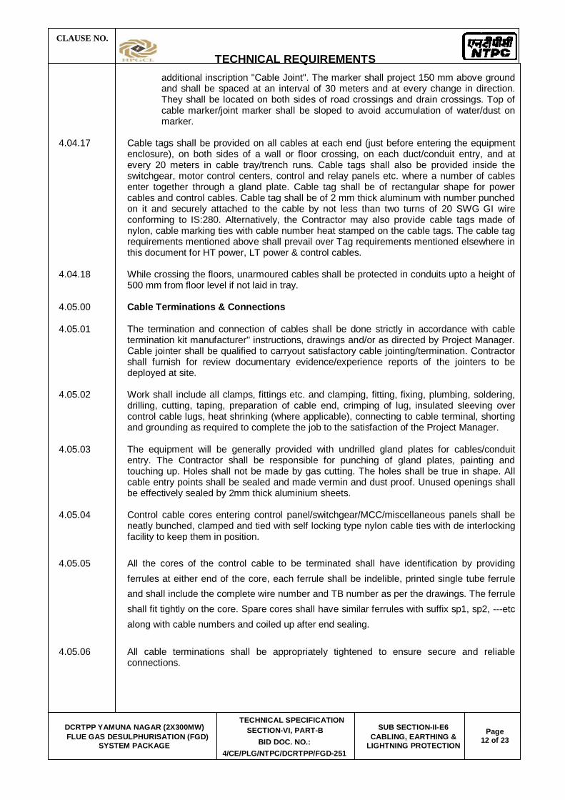
CLAUSE NO.
TECHNICAL REQUIREMENTS
DCRTPP YAMUNA NAGAR (2X300MW)
FLUE GAS DESULPHURISATION (FGD) SYSTEM PACKAGE
TECHNICAL SPECIFICATION SECTION-VI, PART-B
BID DOC. NO.: 4/CE/PLG/NTPC/DCRTPP/FGD-251
SUB SECTION-II-E6 CABLING, EARTHING &
LIGHTNING PROTECTION Page
12 of 23
additional inscription "Cable Joint". The marker shall project 150 mm above ground and shall be spaced at an interval of 30 meters and at every change in direction. They shall be located on both sides of road crossings and drain crossings. Top of cable marker/joint marker shall be sloped to avoid accumulation of water/dust on marker.
4.04.17 Cable tags shall be provided on all cables at each end (just before entering the equipment
enclosure), on both sides of a wall or floor crossing, on each duct/conduit entry, and at every 20 meters in cable tray/trench runs. Cable tags shall also be provided inside the switchgear, motor control centers, control and relay panels etc. where a number of cables enter together through a gland plate. Cable tag shall be of rectangular shape for power cables and control cables. Cable tag shall be of 2 mm thick aluminum with number punched on it and securely attached to the cable by not less than two turns of 20 SWG GI wire conforming to IS:280. Alternatively, the Contractor may also provide cable tags made of nylon, cable marking ties with cable number heat stamped on the cable tags. The cable tag requirements mentioned above shall prevail over Tag requirements mentioned elsewhere in this document for HT power, LT power & control cables.
4.04.18 While crossing the floors, unarmoured cables shall be protected in conduits upto a height of
500 mm from floor level if not laid in tray. 4.05.00 Cable Terminations & Connections 4.05.01 The termination and connection of cables shall be done strictly in accordance with cable
termination kit manufacturer'' instructions, drawings and/or as directed by Project Manager. Cable jointer shall be qualified to carryout satisfactory cable jointing/termination. Contractor shall furnish for review documentary evidence/experience reports of the jointers to be deployed at site.
4.05.02 Work shall include all clamps, fittings etc. and clamping, fitting, fixing, plumbing, soldering,
drilling, cutting, taping, preparation of cable end, crimping of lug, insulated sleeving over control cable lugs, heat shrinking (where applicable), connecting to cable terminal, shorting and grounding as required to complete the job to the satisfaction of the Project Manager.
4.05.03 The equipment will be generally provided with undrilled gland plates for cables/conduit
entry. The Contractor shall be responsible for punching of gland plates, painting and touching up. Holes shall not be made by gas cutting. The holes shall be true in shape. All cable entry points shall be sealed and made vermin and dust proof. Unused openings shall be effectively sealed by 2mm thick aluminium sheets.
4.05.04 Control cable cores entering control panel/switchgear/MCC/miscellaneous panels shall be
neatly bunched, clamped and tied with self locking type nylon cable ties with de interlocking facility to keep them in position.
4.05.05 All the cores of the control cable to be terminated shall have identification by providing ferrules at either end of the core, each ferrule shall be indelible, printed single tube ferrule and shall include the complete wire number and TB number as per the drawings. The ferrule shall fit tightly on the core. Spare cores shall have similar ferrules with suffix sp1, sp2, ---etc along with cable numbers and coiled up after end sealing.
4.05.06 All cable terminations shall be appropriately tightened to ensure secure and reliable
connections.

CLAUSE NO.
TECHNICAL REQUIREMENTS
DCRTPP YAMUNA NAGAR (2X300MW)
FLUE GAS DESULPHURISATION (FGD) SYSTEM PACKAGE
TECHNICAL SPECIFICATION SECTION-VI, PART-B
BID DOC. NO.: 4/CE/PLG/NTPC/DCRTPP/FGD-251
SUB SECTION-II-E6 CABLING, EARTHING &
LIGHTNING PROTECTION Page
13 of 23
5.00.00 EARTHING SYSTEM
5.01.00 Earthing system shall be in strict accordance with IS:3043 and Indian Electricity Rules/Acts.
The earthing system shall be designed for a life expectancy of at least forty (40) years, for a system fault current of 50 kA for 1.0 sec. The minimum rate of corrosion of steel for selection of earthing conductor shall be 0.12mm per year.
Earthing system network/earthmat shall be interconnected mesh of mild steel rods buried in ground in the plant. All areas under contractor scope of supply shall be interconnected together by minimum two parallel conductors. The Contractor shall furnish the detailed design and calculations for Employer's approval. Contractor shall obtain all necessary statutory approvals for the system. All the columns shall be earthed by nearby risers and earthmat grid spacing shall be minimum 10 mts. Minimum two nos of risers shall be provided for each equipment in SG area. Separate dedicated riser shall be provided for C&I earthing purpose and also for Lightning down conductor connection purpose. Sufficient nos of risers near the equipment shall be provided as per the system requirement.
5.02.00 The earth conductors shall be free from pitting, laminations, rust, scale and other electrical,
mechanical defects 5.03.00 The material of the earthing conductors shall be as follows: 1) Conductors above ground level - Galvanized steel and in built up trenches. 2) Conductors buried in earth - Mild steel 3) Earth electrodes - Mild steel rod 5.04.00 The sizes of earthing conductors for various electrical equipments shall be as below: Equipment Earth Earth conductor above conductor ground level & in built- buried in up trenches earth a) Main earth grid Min 40 mm dia. MS 65 x 8mm GS flat rod or as per actual calculation whichever is more b) 33kV/11kV/6.6kV/3.3 kV/ --- 65 x 8mm GS flat switchgear equipment and 415V switchgear c) 415 V MCC/ Distribution --- 50 x 6mm GS flat boards / Transformers d) LT Motors above 125 KW --- 50 x 6mm GS flat 25 KW to 125 KW --- 25 x 6mm GS flat 1KW to 25 KW --- 25 x 3mm GS flat
CLAUSE NO.
TECHNICAL REQUIREMENTS
DCRTPP YAMUNA NAGAR (2X300MW)
FLUE GAS DESULPHURISATION (FGD) SYSTEM PACKAGE
TECHNICAL SPECIFICATION SECTION-VI, PART-B
BID DOC. NO.: 4/CE/PLG/NTPC/DCRTPP/FGD-251
SUB SECTION-II-E6 CABLING, EARTHING &
LIGHTNING PROTECTION Page
14 of 23
Fractional House power motor --- 8 SWG GS wire e) Control panel & control desk --- 25 x 3 mm GS flat f) Push button station / Junction --- 8 SWG GI wire Box g) Columns, structures, cable --- 50 x 6mm GS flat trays and bus ducts enclosures h) Crane, rails, rail tracks & other 25 x 6mm GS flat non-current carrying metal parts 5.05.00 Metallic frame of all electrical equipment shall be earthed by two separate and distinct
connections to earthing system, each of 100% capacity, Crane rails, tracks, metal pipes and conduits shall also be effectively earthed at two points. Steel RCC columns, metallic stairs, and rails etc. of the building housing electrical equipment shall be connected to the nearby earthing grid conductor by one earthing ensured by bonding the different sections of hand rails and metallic stairs. Metallic sheaths/screens, and armour of multi-core cables shall be earthed at both ends. Metallic Sheaths and armour of single core cables shall be earthed at switchgear end only unless otherwise approved. Every alternate post of the switchyard fence shall be connected to earthing grid by one GS flat and gates by flexible lead to the earthed post. Railway tracks within the plant area shall be bonded across fish plates and connected to earthing grid at several locations. Portable tools, appliances and welding equipment shall be earthed by flexible insulated cable.
5.06.00 Each continuous laid lengths of cable tray shall be earthed at minimum two places by G.S.
flats to earthing system, the distance between earthing points shall not exceed 30 meter. Wherever earth mat is not available, necessary connections shall be done by driving an earth electrode in the ground
5.07.00 Neutral points of HT transformer shall be earthed through NG resistors. The Contractor shall
connect the NGR earthing point to earth electrodes by suitable earth conductors. 5.08.00 Neutral connections and metallic conduits/pipes shall not be used for the equipment
earthing. Lightning protection system down conductors shall not be connected to other earthing conductors above the ground level.
5.09.00 Connections between earth leads and equipment shall normally be of bolted type. Contact
surfaces shall be thoroughly cleaned before connections. Equipment bolted connections after being tested and checked shall be painted with anti corrosive paint/compound.
5.10.00 Suitable earth risers as approved shall be provided above finished floor/ground level, if the
equipment is not available at the time of laying of main earth conductor. 5.11.00 Connections between equipment earthing leads and between main earthing conductors
shall be of welded type. For rust protection the welds should be treated with red lead compound and afterwards thickly coated with bitumen compound. All welded connections shall be made by electric arc welding.
5.12.00 Resistance of the joint shall not be more than the resistance of the equivalent length of
conductors. 5.13.00 Earthing conductors buried in ground shall be laid minimum 600 mm below grade level
unless otherwise indicated in the drawing. Back filling material to be placed over buried conductors shall be free from stones and harmful mixtures. Back filling shall be placed in layers of 150 mm.
CLAUSE NO.
TECHNICAL REQUIREMENTS
DCRTPP YAMUNA NAGAR (2X300MW)
FLUE GAS DESULPHURISATION (FGD) SYSTEM PACKAGE
TECHNICAL SPECIFICATION SECTION-VI, PART-B
BID DOC. NO.: 4/CE/PLG/NTPC/DCRTPP/FGD-251
SUB SECTION-II-E6 CABLING, EARTHING &
LIGHTNING PROTECTION Page
15 of 23
5.14.00 Earthing conductors embedded in the concrete floor of the building shall have approximately
50 mm concrete cover. 5.15.00 A minimum earth coverage of 300 mm shall be provided between earth conductor and the
bottom of trench/foundation/underground pipes at crossings. Earthing conductors crossing the road can be installed in pipes. Wherever earthing conductor crosses or runs at less than 300 mm distance along metallic structures such as gas, water, steam pipe lines, steel reinforcement in concrete, it shall be bonded to the same.
5.16.00 Earthing conductors along their run on columns, walls, etc. shall be supported by suitable
welding / cleating at interval of 1000mm and 750mm respectively.
5.17.00 Earth pit shall be of treated type & shall be constructed as per IS:3043. Electrodes shall be embedded below permanent moisture level. Minimum spacing between electrodes shall be 600mm. Earth pits shall be treated with salt and charcoal as per IS:3043. Test links shall be provided with bolted arrangement alongwith each earth pit, in order to facilitate measurement of earth resistance as & when required.
5.18.00 On completion of installation continuity of earth conductors and efficiency of all bonds and joints shall be checked. Earth resistance at earth terminations shall be measured and recorded. All equipment required for testing shall be furnished by contractor.
5.19.00 Earthing conductor shall be buried at least 2000mm outside the fence of electrical
installations. Every alternate post of the fences and all gates shall be connected to earthing grid by one lead.
5.20.00 Other Requirements of Earthing System: Standard/Code IEEE 80, IS 3043 Earthing System Life expectancy 40 Years System Fault Level System Fault Level 50 KA for 1 sec Soil resistivity Actual as per site conditions. Min. Steel corrosion 0.12mm/year Depth of burial of main earth conductor 600mm below grade level; where it crosses
trenches, pipes, ducts, tunnels, rail tracks, etc., it shall be at least 300mm below them.
Conductor joints By electric arc welding, with resistance of joint
not more than that of the conductor. Welds to be treated with red lead for rust protection and then coated with bitumen
compound for corrosion protection. Surface resistivity - Gravel 3000 ohm-meter - Concrete 500 ohm-meter

CLAUSE NO.
TECHNICAL REQUIREMENTS
DCRTPP YAMUNA NAGAR (2X300MW)
FLUE GAS DESULPHURISATION (FGD) SYSTEM PACKAGE
TECHNICAL SPECIFICATION SECTION-VI, PART-B
BID DOC. NO.: 4/CE/PLG/NTPC/DCRTPP/FGD-251
SUB SECTION-II-E6 CABLING, EARTHING &
LIGHTNING PROTECTION Page
16 of 23
6.00.00 LIGHTNING PROTECTION SYSTEM 6.01.01 Lightning protection system shall be in strict accordance with IEC: 62305 and latest IS
standards. 6.01.02 Lightning conductor shall be of 25x6mm GS strip when used above ground level and shall
be connected through test link with earth electrode/earthing system 6.01.03 Lightning system shall comprise of air terminations, down conductors, test links, earth
electrode etc. as per approved drawings. 6.02.00 Down Conductors 1. Down conductors shall be as short and straight as practicable and shall follow a
direct path to earth electrode. 2. Each down conductor shall be provided with a test link at 1000 mm above ground
level for testing but it shall be in accessible to interference. No connections other than the one direct to an earth electrode shall be made below a test point.
3. All joints in the down conductors shall be welded type. 4. Down conductors shall be cleated on outer side of building wall, at 750 mm interval
or welded to outside building columns at 1000 mm interval. 5. Lightning conductor on roof shall not be directly cleated on surface of roof.
Supporting blocks of PCC/insulating compound shall be used for conductor fixing at an interval of 1500 mm.
6. All metallic structures within a vicinity of two meters of the conductors shall be
bonded to conductors of lightning protection system. 7. Lightning conductors shall not pass through or run inside GI Conduits. 8. Testing link shall be made of galvanized steel of size 25x 6mm. 9. Pulser system for lightning shall not be accepted. 10. Hazardous areas handling inflammable/explosive materials and associated storage
areas shall be protected by a system of aerial earths. 7.00.00 TESTS 7.01.01 All equipment to be supplied shall be of type tested design. During detail engineering, the
contractor shall submit for Employer's approval the reports of all the type tests as listed in this specification and carried out within last ten years from the date of bid opening. These reports should be for the test conducted on the equipment similar to those proposed to be supplied under this contract and the test(s) should have been either conducted at an independent laboratory or should have been witnessed by a client.
7.01.02 However if the contractor is not able to submit report of the type test(s) conducted within
last ten years from the date of bid opening, or in the case of type test report(s) are not found to be meeting the specification requirements, the contractor shall conduct all such tests under this contract at no additional cost to the Employer either at third party lab or in presence of client/Employers representative and submit the reports for approval.
7.01.03 All acceptance and routine tests as per the specification and relevant standards shall be
carried out. Charges for these shall be deemed to be included in the equipment price.

CLAUSE NO.
TECHNICAL REQUIREMENTS
DCRTPP YAMUNA NAGAR (2X300MW)
FLUE GAS DESULPHURISATION (FGD) SYSTEM PACKAGE
TECHNICAL SPECIFICATION SECTION-VI, PART-B
BID DOC. NO.: 4/CE/PLG/NTPC/DCRTPP/FGD-251
SUB SECTION-II-E6 CABLING, EARTHING &
LIGHTNING PROTECTION Page
17 of 23
7.02.00 Type Test reports shall be furnished for the following 7.02.01 Type tests on Cable Trays support system a) Test 1A:
On main support channel type-C2 for cantilever arms fixed on one side only. A 3.5 meter length of main support channel shall be fixed vertically at each end to a rigid structure as per the fixing arrangement as shown in the enclosed drawing. Eight (8) nos. 750 mm cantilever arms shall be fixed to the main channel and each arm shall be loaded over the outboard 600 mm with a uniform working load of 100 kg. Subsequently a point load of 100 kg shall be applied on arm 2. A uniform proof load on all the arms equal to twice the working load shall be then be applied. Deflections shall be measured at the points shown in the enclosed drawings and at the following load intervals:
i) Working load ii) Working load + point load iii) Off load iv) Proof load + point load v) Off load
The deflection measured at working loads shall not exceed 16mm. The permanent deflection after removing the combination of working load and point load shall not exceed 10 mm at the arm tips and 6 mm on the channel. No collapse of the structure shall occur with a combination of proof load and point load applied.
B) Test 1B:
Test 1A shall be repeated with Eight Cantilever arms uniformly loaded and with the same point load on arm 2
Test 2: On Main support channel type -C2 for cantilever arms fixed on both
sides
a) Test 2A: A 3.5 m length of main support channel C2 for cantilever arms fixing on both sides shall be fixed at each end to rigid structure as per the fixing arrangement as shown in the enclosed drawing. Six (6), 750 mm cantilever arms shall be attached to each sides and each arm uniformly loaded to a working load of 100 kg over the out board 600 mm. A point load of 100 kg shall than be applied to arm 2, followed by a uniform proof load of twice the working load on all the arms; deflection shall be measured at points shown in the enclosed drawings at the following load intervals.
i) Working load ii) Working load + Point load iii) Off load iv) Proof load + Point load

CLAUSE NO.
TECHNICAL REQUIREMENTS
DCRTPP YAMUNA NAGAR (2X300MW)
FLUE GAS DESULPHURISATION (FGD) SYSTEM PACKAGE
TECHNICAL SPECIFICATION SECTION-VI, PART-B
BID DOC. NO.: 4/CE/PLG/NTPC/DCRTPP/FGD-251
SUB SECTION-II-E6 CABLING, EARTHING &
LIGHTNING PROTECTION Page
18 of 23
v) Off load
The deflection measured at working loads shall not exceed 16mm. The permanent deflection after removing the combination of working load and point load shall not exceed 10 mm at the arm tips and 6 mm on the channel. No collapse of the structure shall occur with a combination of proof load and point load applied
b) Test 2 B: The test 2 A shall be repeated with the assembly but with an asymmetrical
load on the C2 column and point load applied to arm 8. The 100 kg and 200 kg uniformly distributed loads shall be applied to the upper three arms on one side and the lower three arms on the opposite side.
Test 3: Tests on Channel Fixed on Beam/Floor A length of main support channel section shall be fixed to steel structure/floor and have
loads applied as shown in the drawing enclosed and as detailed below a) Test 3A : A length of steel structure shall be rigidly supported. It should be fitted on a
meter length of channel section using beam clamps welded/bolted. A point load of 1200 kg shall be applied to the centre point via two brackets. No distortion or pulling of the components shall take place.
b) Test 3B: With the components assembled as in Test 3A, two perpendicular point loads
of 600 kg shall be simultaneously applied at positions 150 mm either side of the centre line, no distortion or pulling of the components shall take place.
c) Test 3C: With the components assembled as in Test 3A, a perpendicular point load
shall be applied at a point 150 mm on one side of the centre line. The load shall be gradually increased to the maximum value that can be
applied without causing distortion or pulling of the components. This value shall be recorded.
Test 4 : Channel Insert Test A 2.5 m length of C1 channel fixed to the concrete wall/ steel structure as per
actual site installation conditions. 6 nos. of 750 mm cantilever arms shall be attached to C1 channel as shown in enclosed drawing. Each arm uniformly loaded to a working load of 100 kg over the out board 600 mm. A point load of 100 kg shall than be applied to arm 2, followed by a uniform proof load of twice the working load on all the arms; deflection shall be measured at points shown in the enclosed drawings at the following load intervals.
i) Working Load
ii) Working Load + Point Load
iii) Off Load
iv) Proof Load + Point Load
v) Off load
The deflection measured at working loads shall not exceed 16mm. The permanent deflection after removing the combination of working load and point load shall not exceed 10

CLAUSE NO.
TECHNICAL REQUIREMENTS
DCRTPP YAMUNA NAGAR (2X300MW)
FLUE GAS DESULPHURISATION (FGD) SYSTEM PACKAGE
TECHNICAL SPECIFICATION SECTION-VI, PART-B
BID DOC. NO.: 4/CE/PLG/NTPC/DCRTPP/FGD-251
SUB SECTION-II-E6 CABLING, EARTHING &
LIGHTNING PROTECTION Page
19 of 23
mm at the arm tips and 6 mm on the channel. No collapse of the structure shall occur with a combination of proof load and point load applied
Test 5 : Channel nut slip characteristics (what ever applicable)
Tests 5A1,5A2,5A3 : A length of channel C1 section 200mm long shall have fitted bracket with the two bolt fixing as shown in drawing enclosed.
With loads applied at the position shown in drawing enclosed nut slip shall be determined with bolt torque of 30NM, 50 NM and 65 NM No fewer than three measurements shall be made for each torque setting.
A minimum loading of 720 kg shall be obtained before nut slip with bolt torque of 65 NM.
Tests 5B1,5B2, 5B3: The length of channel C1 section 200 mm long shall have fitted
bracket with the one bolt fixing as shown in drawing enclosed. With loads applied at the position shown in drawing, nut slip shall be determined with bolt torques of 30 NM, 50 NM and 65 NM. No fewer than three measurements shall be made for each torque setting.
A minimum loading of 350 kg shall be obtained before nut slip with a bolt torque of 65
NM. Test 6 Weld Integrity Test After deflection test as per test 1A, 1B, 2, 3 & 4 weld integrity shall be checked by
magnetic particle inspection to detect sub-surface cracks developed, if any. 7.02.02 Cable termination kit and straight through joints should have been tested as per IS:13573
for 3.3kV grade & above. 7.03.00 Routine/ Acceptance Tests 7.03.01 Routine Tests
a) Routine tests as per specification and applicable standards shall be carried out on all requirements/items covered in the specification.
b) Physical & dimensional check on all equipments as per approved
drawings/standards . c) HV/IR as applicable. d) Check/measurement of thickness of paint/zinc coating/nickel-chrome plating as per
specification & applicable standard. 7.03.02 Acceptance Test a) Galvanising Tests as per applicable standards b) Welding checks
c) Deflection tests on cable trays:

CLAUSE NO.
TECHNICAL REQUIREMENTS
DCRTPP YAMUNA NAGAR (2X300MW)
FLUE GAS DESULPHURISATION (FGD) SYSTEM PACKAGE
TECHNICAL SPECIFICATION SECTION-VI, PART-B
BID DOC. NO.: 4/CE/PLG/NTPC/DCRTPP/FGD-251
SUB SECTION-II-E6 CABLING, EARTHING &
LIGHTNING PROTECTION Page
20 of 23
d) One piece each of 2.5m length of cable tray of 300mm & above shall be taken as
sample from each offered lot. It shall be supported at both end & loaded with uniform load of 76 kg/meter along the length of cable tray. The maximum deflection at the mid-span of each size shall not exceed 7mm.
d) Proof load tests on cable tray support system
i) Tests on Main Support Channel shall be done if only C1 Channel are in scope of supply and cantilever arms shall be fitted on one side. This test shall be same as test 4 of type test.
ii) Test on Main Support Channel shall be done with C2 channel and cantilever arms
fitted on both sides, if C2 channels are in scope of supply. This test shall be same as test 2A of type test. Then test (i) above shall not be done.
iii) Nut slip characteristic test (it shall support minimum load of 350kg before nut slips with a bolt torque of 65 NM). This test shall be same as test 5B3 of type test.
The procedure for carrying out tests at “d” above shall be as per details given in Type Tests in specification thereafter Die-Penetration test shall be carried out to check weld integrity.
e) The above acceptance tests shall be done only on one sample from each offered
lot. 8.00.00 COMMISSIONING 8.01.01 The Contractor shall carry out the following commissioning tests and checks after
installation at site. In addition the Contractor shall carry out all other checks and tests as recommended by the Manufacturers or else required for satisfactory performance.
8.01.02 Cables a) Check for physical damage b) Check for insulation resistance before and after termination/jointing. c) HT cables shall be pressure tested (test voltage as per IS:7098) before
commissioning. d) Check of continuity of all cores of the cables. e) Check for correctness of all connections as per relevant wiring diagrams. Any minor
modification to the panel wiring like removing/inserting, shorting, change in terminal connections, etc., shall be carried out by the Contractor.
f) Check for correct polarity and phasing of cable connections. g) Check for proper earth connections for cable glands, cable boxes, cable armour,
screens, etc. h) Check for provision of correct cable tags, core ferrules and tightness of connections. 8.02.00 Cable trays / supports and accessories

CLAUSE NO.
TECHNICAL REQUIREMENTS
DCRTPP YAMUNA NAGAR (2X300MW)
FLUE GAS DESULPHURISATION (FGD) SYSTEM PACKAGE
TECHNICAL SPECIFICATION SECTION-VI, PART-B
BID DOC. NO.: 4/CE/PLG/NTPC/DCRTPP/FGD-251
SUB SECTION-II-E6 CABLING, EARTHING &
LIGHTNING PROTECTION Page
21 of 23
1) Check for proper galvanizing/painting and identification number of the cable
trays/supports and accessories. 2) Check for continuity of cable trays over the entire route. 3) Check that all sharp corners, burrs, and waste materials have been removed from
the trays supports. 4) Check for earth continuity and earth connection of cable trays. 8.03.00 Earthing and Lightning protection system 1) Earth continuity checks. 2) Earth resistance of the complete system as well as sub-system. 9.00.00 ELECTRICAL LAYOUT PHILOSOPHY: While developing the layout the bidder must give due consideration to the following
requirements:
a) Adequate distance shall be maintained between the transformers. As basic guidelines following norms will be adhered to:
1) Transformers shall be separated from the adjacent building/structures and from each other by a minimum distance as defined below or by a fire wall of two hours of fire resisting of height at least 600 mm above bushing / pressure relief vent whichever is higher.
Oil capacity of individual transformer Clear separating distance
(in liters) (in meters)
5,000 to 10,000 8.0
10,001 to 20,000 10.0
20,001 to 30,000 12.5
Over 30,001 15.0
2) In case of auxiliary transformers having an aggregate oil capacity in excess of 2300 liters but individual oil capacity of less than 5000 liters, the maximum separating distance between transformers and surrounding building shall be at least 6M unless they are separated by fire separating walls or are protected by high velocity spray system.
3.) Rail track shall be provided in Transformer yard for movement of each transformer. The rail track in Transformer yard shall be connected with TG area rail track The Foundation top of transformer & rail top shall be at EL +/- 0.0M. Bus duct support or Transformer body shall be at least 8.0M from A-Row of TG building to clear the movement of GT/ Stator/UT/ST/UAT on rail line. Jacking pads shall be provided where the rail track changes the direction. Mooring post shall be provided on rail track for handling the transformers.

CLAUSE NO.
TECHNICAL REQUIREMENTS
DCRTPP YAMUNA NAGAR (2X300MW)
FLUE GAS DESULPHURISATION (FGD) SYSTEM PACKAGE
TECHNICAL SPECIFICATION SECTION-VI, PART-B
BID DOC. NO.: 4/CE/PLG/NTPC/DCRTPP/FGD-251
SUB SECTION-II-E6 CABLING, EARTHING &
LIGHTNING PROTECTION Page
22 of 23
4) For each transformer a pit shall be provided all around at a distance of 1.5 m (minimum) from transformer outer edge. A sump pit shall be provided for each pit. A common oil retention pit per unit shall be provided to hold oil quantity of the largest transformer (by volume) & 10 minutes of water quantity of HVW spray system for the largest transformer. Sump pit of individual transformer shall be connected to common oil retention pit of that unit.
5) Rail track shall be provided for all outdoor transformers up to road for movement
of each transformer of size more than or equal to 7.5MVA Transformer. Jacking pads shall be provided where the rail track changes the direction. Jacking pad shall also be provided at the location of installation of transformer and mooring post shall be provided on rail track for handling the transformers.
6.) The Transformer fencing shall be at 1.0 M (minimum) distance from the pit wall.
The Height of fencing shall be 2.5 M (minimum) and fencing shall have personal entry gate and removable type fencing/gate for transformer withdrawal.
7) The transformer firewall, pit sizing and clearances from adjacent
building/structures etc. shall be as per IS 1646/CBIP manual on Transformer
8) However, for all outdoor transformers of oil capacity less than 2000 litre, a trench of suitable size shall be provided all around at a distance of 1.0 m (minimum) from transformer outer edge. A sump pit shall be provided for each trench.
b) Layout requirements for Electrical MCC/switchgear rooms
1. Separate Switchgear Rooms shall be provided for each unit. For TG building, all HT boards shall be provided in HT switchgear room at only one floor and all LT boards shall be provided in LT switchgear room at only one floor
2. The following clearances shall be maintained for HT Switchboard.
a.) Front Clearance
i) For one Row of Swgr. - 2.0 M (Min)
ii) For two Rows of Swgr. - 2.5 M (Min)
b.) Back Clearance - 1.5 M (Min.)
c.) Side Clearance Min. 800 mm, however provision to be made for any additional panel in future at both ends. Therefore end clearance shall be 800+width of panel (including spare panels/dummy panels etc.)
3. The following clearances shall be maintained for LT Switchboard.
a.) Front Clearance
i) For one Row of Swgr - 1.5M (Min) ii) For two Rows of Swgr - 1.5/1.75M depending upon the depth of
panels etc
b.) Back Clearance i) For single front - 1.0M (Min)

CLAUSE NO.
TECHNICAL REQUIREMENTS
DCRTPP YAMUNA NAGAR (2X300MW)
FLUE GAS DESULPHURISATION (FGD) SYSTEM PACKAGE
TECHNICAL SPECIFICATION SECTION-VI, PART-B
BID DOC. NO.: 4/CE/PLG/NTPC/DCRTPP/FGD-251
SUB SECTION-II-E6 CABLING, EARTHING &
LIGHTNING PROTECTION Page
23 of 23
ii) For double front - 1.5M (Min)
c.) Side Clearance Min. 800 mm, however provision to be made for any additional panel in future at both ends. Therefore end clearance shall be 800 mm + width of panel. For offsite areas, HT Switchboard clearances shall be followed wherever both LT & HT switch boards are in the same MCC room.
4. Height of HT/LT Switchgear Room and Boiler MCC room
i) With Bus Duct – 4.5 m (min) ii) Without Bus Duct – 4.0 m (min)
Further no vertical bracings shall be envisaged in HT/LT switchgear room and associated cable vault area.
5. Cable trench/Cable vault
For LT switchgear/MCC room at EL 0.0M, minimum 1400 wide x 1400 deep cable trench shall be provided to route the cables. Horizontal cable trays shall be routed in cable trenches.
c) Minimum clear working space 1200mm around the equipment d) In buildings having MCC, minimum 2 fire door along with one rolling shutter of adequate
size/capacity shall be provided.
e) The cable entry and exit from switchgear room shall be from 1.5 mtr (minimum) above FGL.


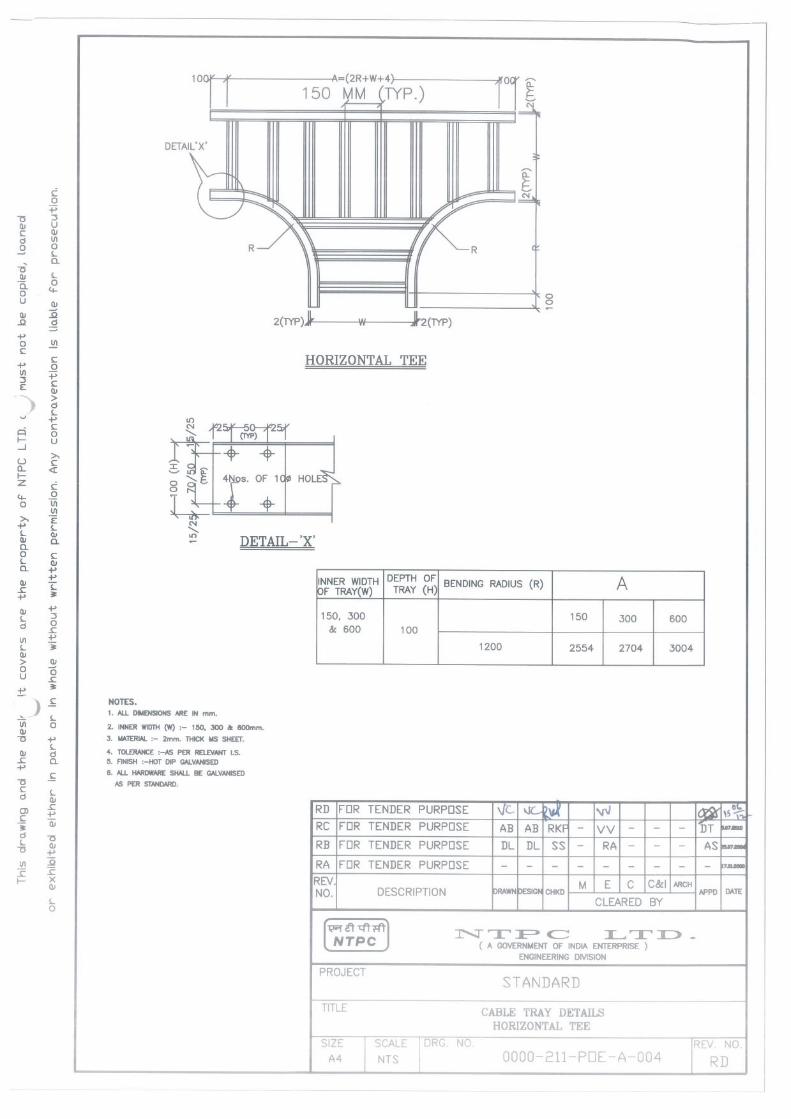
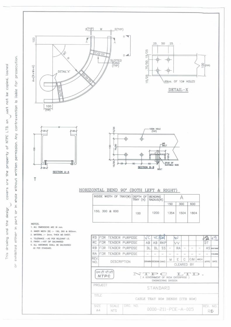


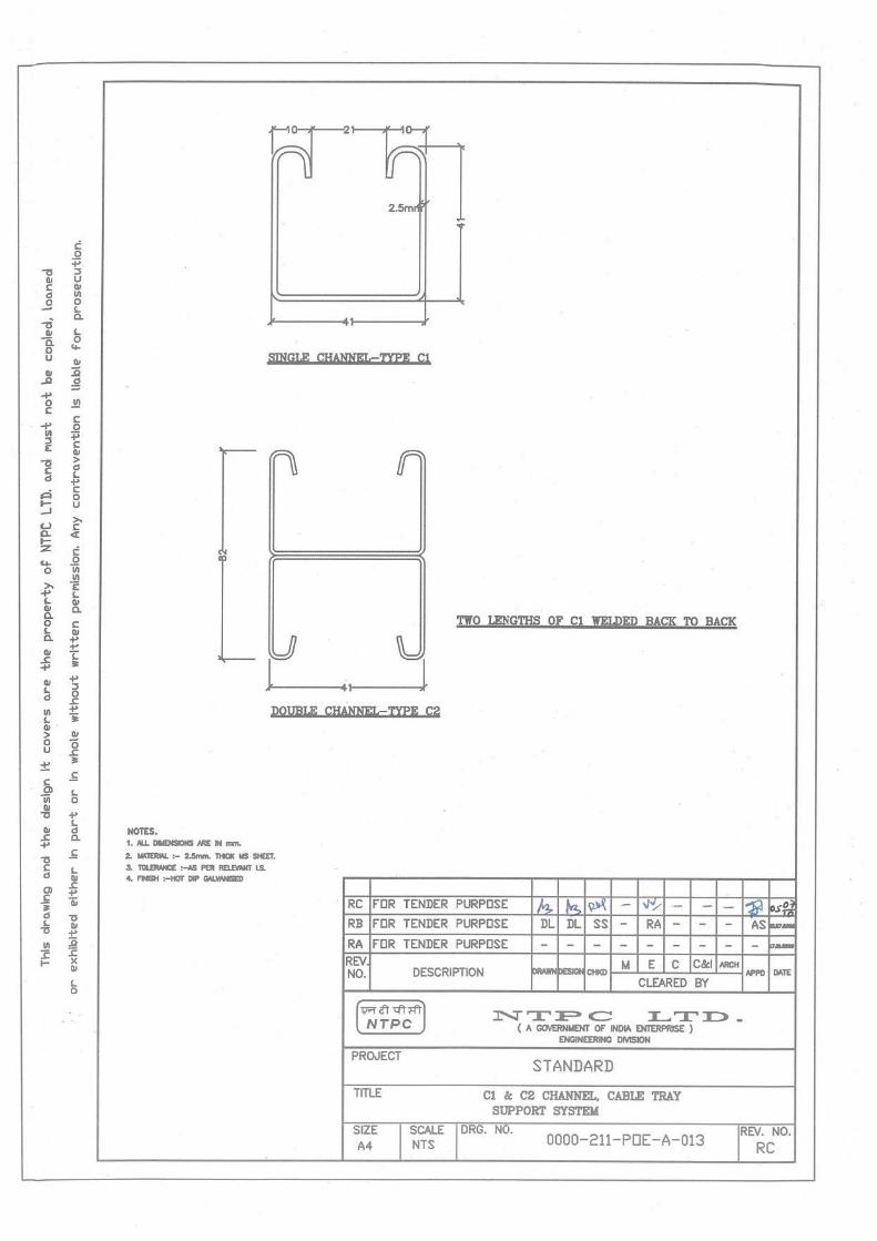
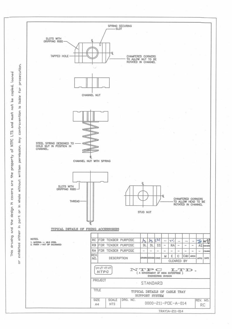


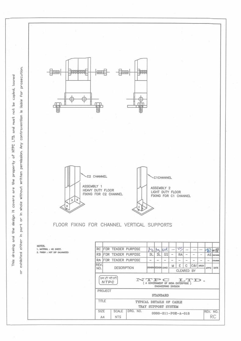
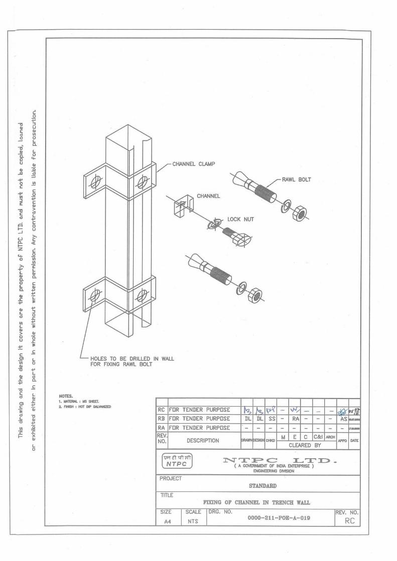


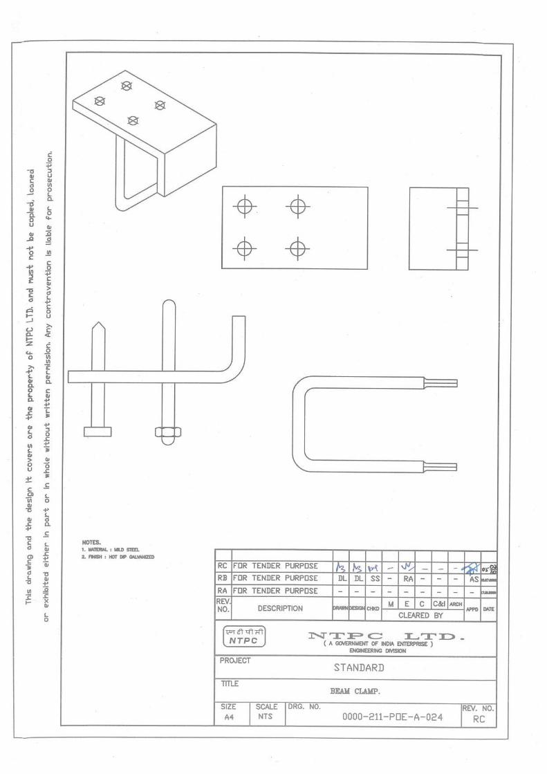

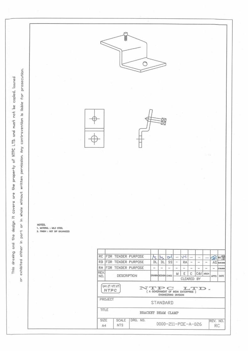


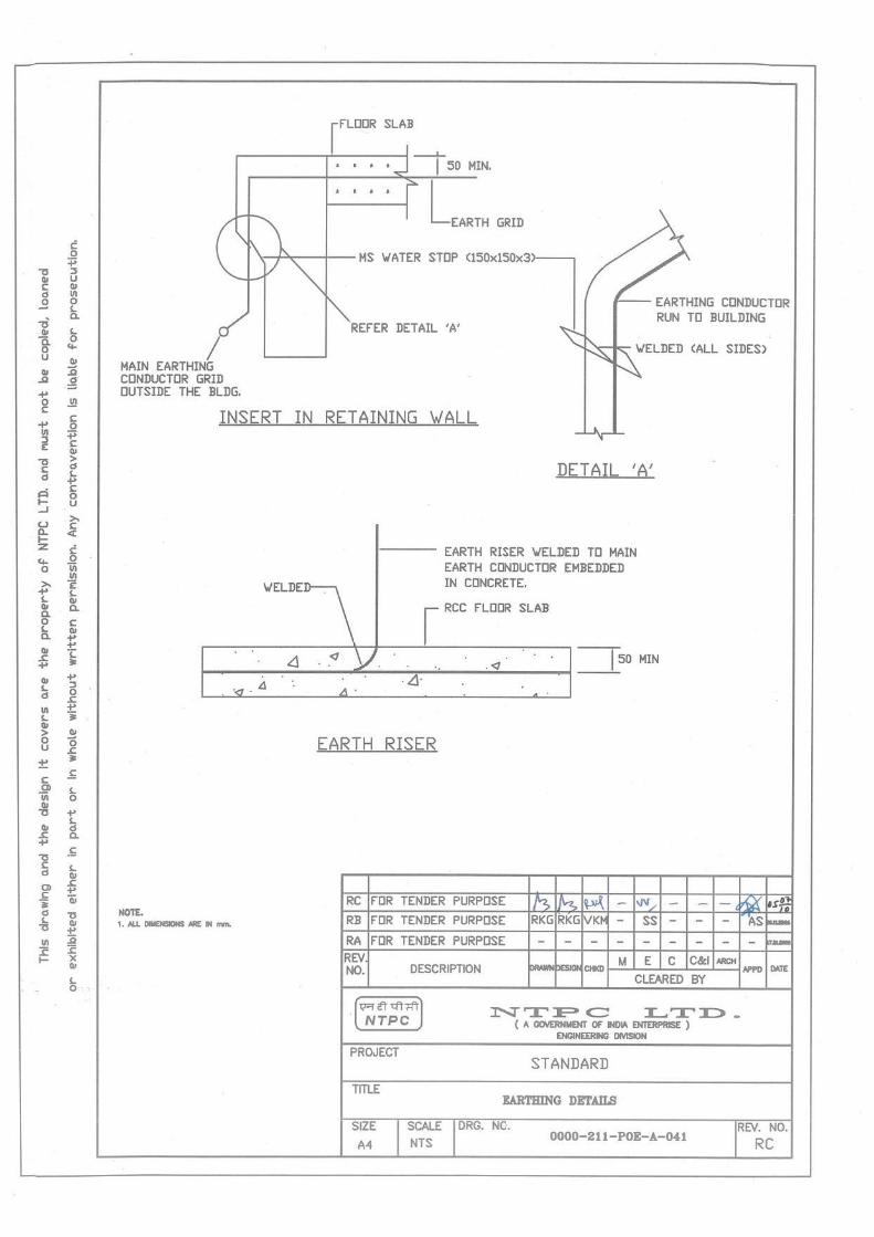


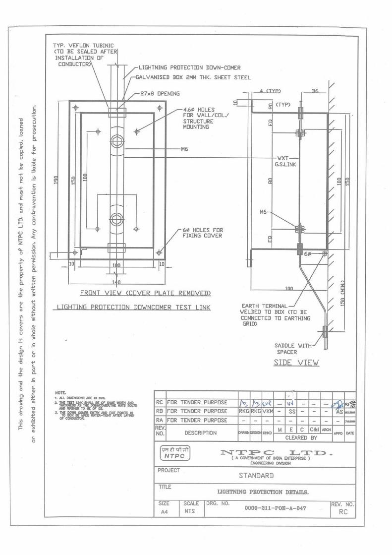

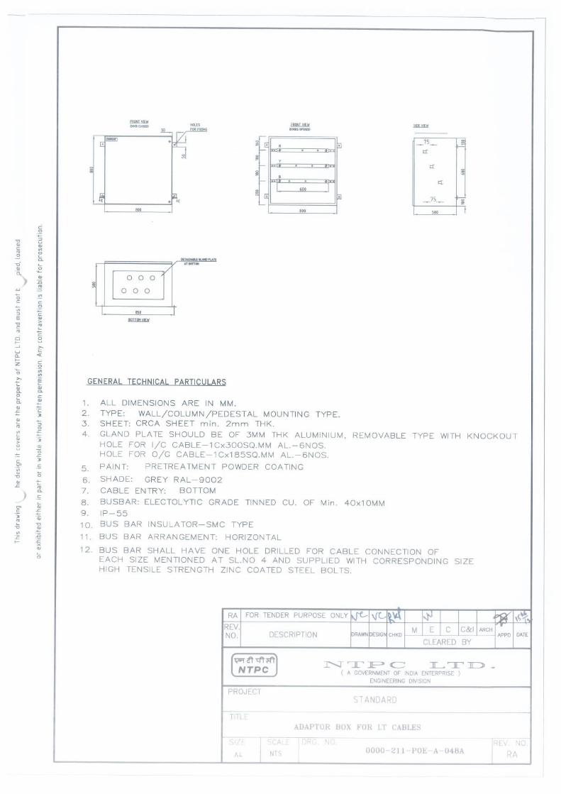
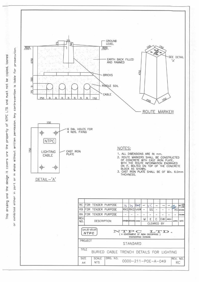
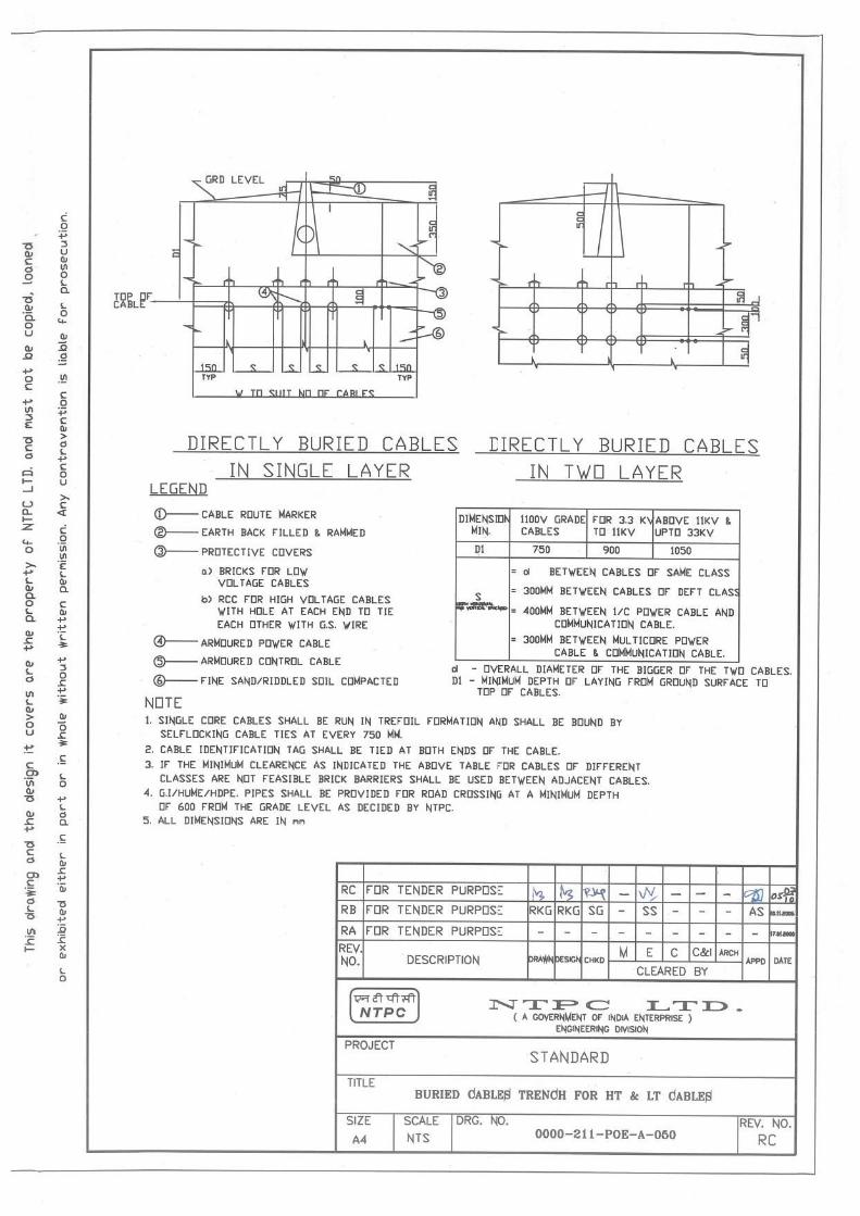

PRODUCED BY AN AUTODESK EDUCATIONAL PRODUCTPR
STAN
DA
RD


![[Sub-System 1 Name] - Rochester Institute of …edge.rit.edu/content/P15484/public/Detailed Design... · Web viewCritical Sub-System Design Sub-System Design P15484 – Solar Assisted](https://static.fdocuments.in/doc/165x107/5ea34d453ce6a81eac37112b/sub-system-1-name-rochester-institute-of-edgeriteducontentp15484publicdetailed.jpg)