Part and tooling design - Tritan Mold It · Part and tooling design ... Tooling design review...
31
Part and tooling design Eastman Tritan™ copolyester
Transcript of Part and tooling design - Tritan Mold It · Part and tooling design ... Tooling design review...
Part and tooling design
Eastman Tritan™ copolyester
Part and tooling design
Process
Part design
Tooling design
High cavitation considerations
Process
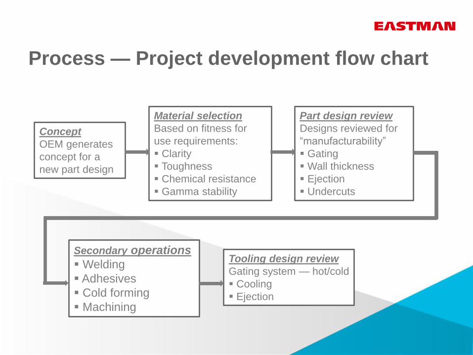
Process — Project development flow chart
Concept
OEM generates
concept for a
new part design
Part design review
Designs reviewed for
“manufacturability”
Gating
Wall thickness
Ejection
Undercuts
Tooling design review
Gating system — hot/cold
Cooling
Ejection
Material selection
Based on fitness for
use requirements:
Clarity
Toughness
Chemical resistance
Gamma stability
Secondary operations
Welding
Adhesives
Cold forming
Machining
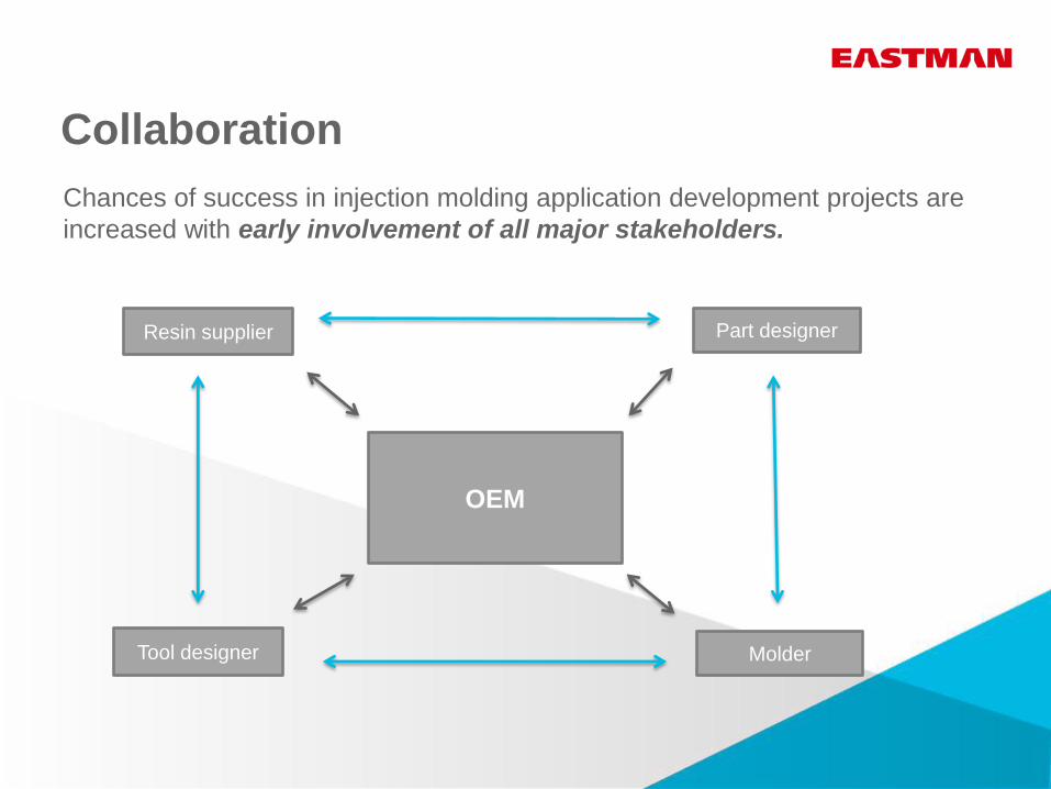
Collaboration
OEM
Part designer
Molder Tool designer
Resin supplier
Chances of success in injection molding application development projects are
increased with early involvement of all major stakeholders.

Benefits of collaboration
Lower scrap rate
Optimized cycle times
Optimized part
performance
Reduced product
development time
Greater return on investment for everyone
Part design
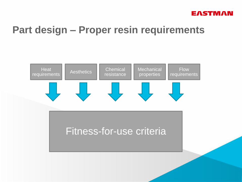
Fitness-for-use criteria
Aesthetics Chemical resistance
Mechanical properties
Flow requirements
Heat requirements
Part design – Proper resin requirements
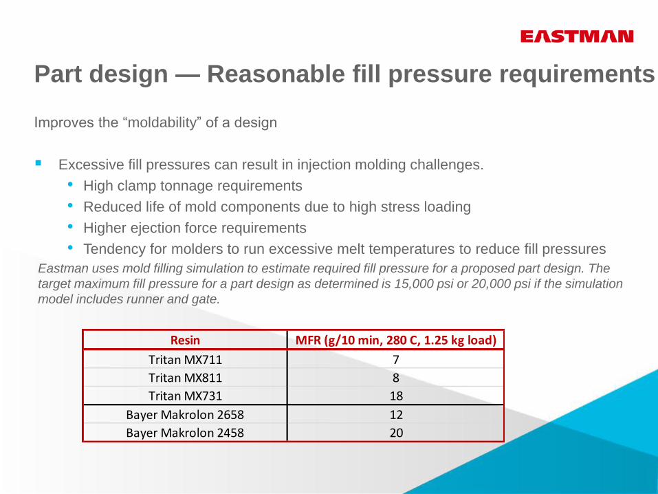
Part design — Reasonable fill pressure requirements
Improves the “moldability” of a design
Excessive fill pressures can result in injection molding challenges.
• High clamp tonnage requirements
• Reduced life of mold components due to high stress loading
• Higher ejection force requirements
• Tendency for molders to run excessive melt temperatures to reduce fill pressures
Eastman uses mold filling simulation to estimate required fill pressure for a proposed part design. The
target maximum fill pressure for a part design as determined is 15,000 psi or 20,000 psi if the simulation
model includes runner and gate.
Resin MFR (g/10 min, 280 C, 1.25 kg load)
Tritan MX711 7
Tritan MX811 8
Tritan MX731 18
Bayer Makrolon 2658 12
Bayer Makrolon 2458 20
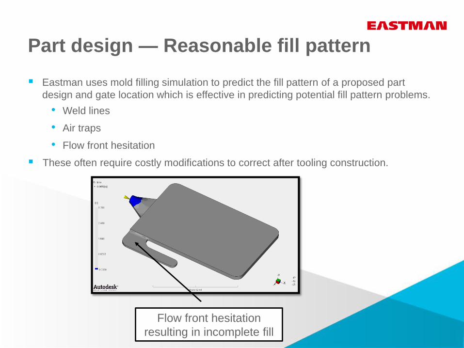
Part design — Reasonable fill pattern
Eastman uses mold filling simulation to predict the fill pattern of a proposed part
design and gate location which is effective in predicting potential fill pattern problems.
• Weld lines
• Air traps
• Flow front hesitation
These often require costly modifications to correct after tooling construction.
Flow front hesitation
resulting in incomplete fill
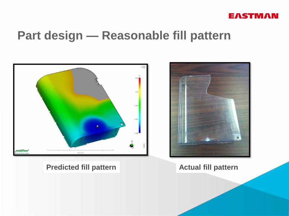
Part design — Reasonable fill pattern
Predicted fill pattern Actual fill pattern
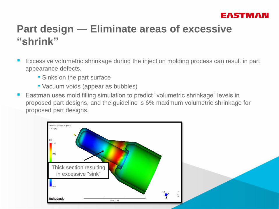
Part design — Eliminate areas of excessive
“shrink”
Excessive volumetric shrinkage during the injection molding process can result in part
appearance defects.
• Sinks on the part surface
• Vacuum voids (appear as bubbles)
Eastman uses mold filling simulation to predict “volumetric shrinkage” levels in
proposed part designs, and the guideline is 6% maximum volumetric shrinkage for
proposed part designs.
Thick section resulting
in excessive “sink”
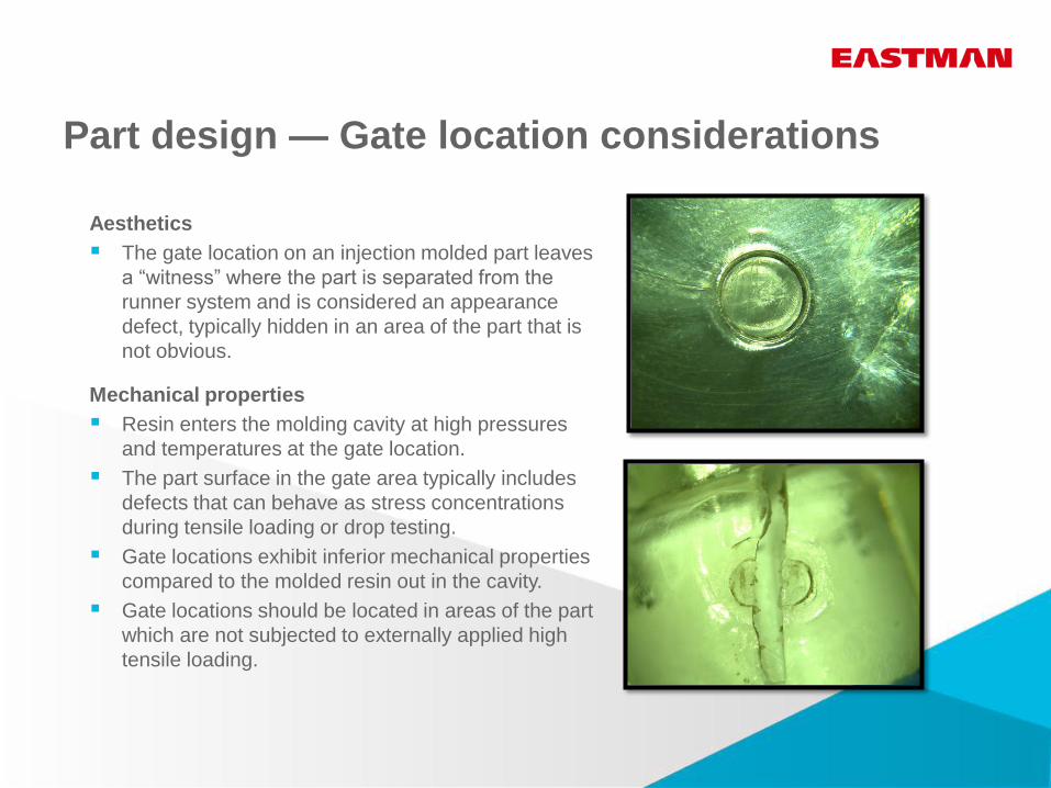
Part design — Gate location considerations
Aesthetics
The gate location on an injection molded part leaves
a “witness” where the part is separated from the
runner system and is considered an appearance
defect, typically hidden in an area of the part that is
not obvious.
Mechanical properties
Resin enters the molding cavity at high pressures
and temperatures at the gate location.
The part surface in the gate area typically includes
defects that can behave as stress concentrations
during tensile loading or drop testing.
Gate locations exhibit inferior mechanical properties
compared to the molded resin out in the cavity.
Gate locations should be located in areas of the part
which are not subjected to externally applied high
tensile loading.
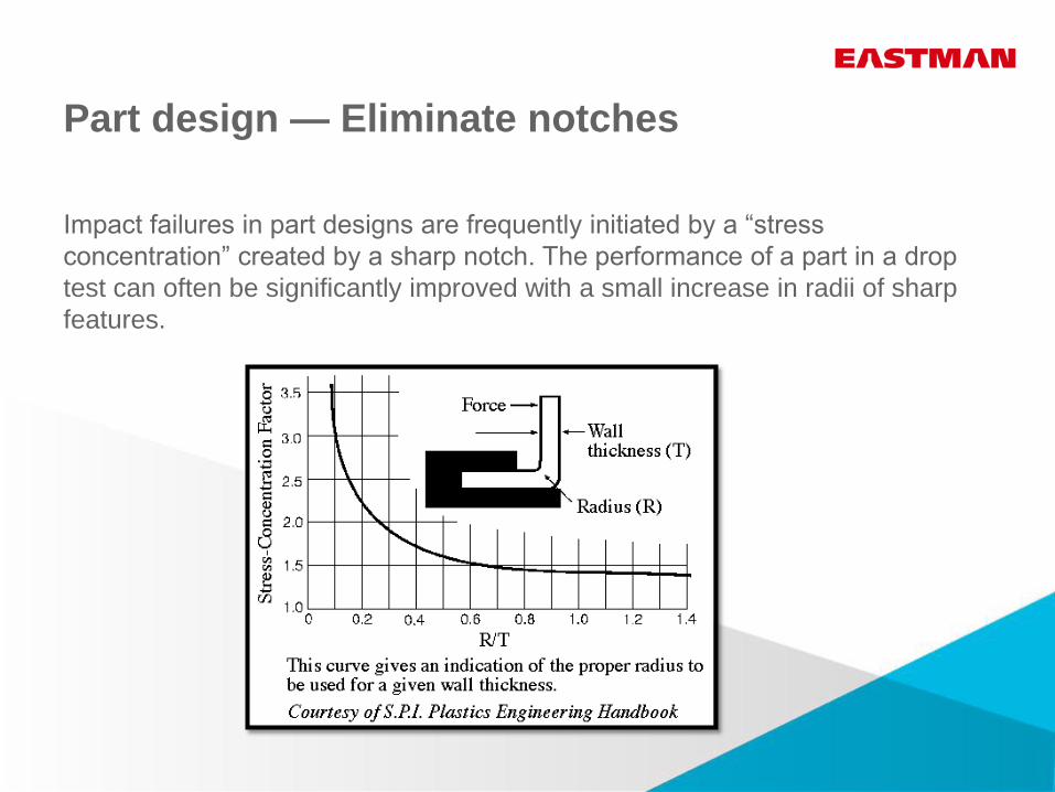
Part design — Eliminate notches
Impact failures in part designs are frequently initiated by a “stress
concentration” created by a sharp notch. The performance of a part in a drop
test can often be significantly improved with a small increase in radii of sharp
features.
Tooling design
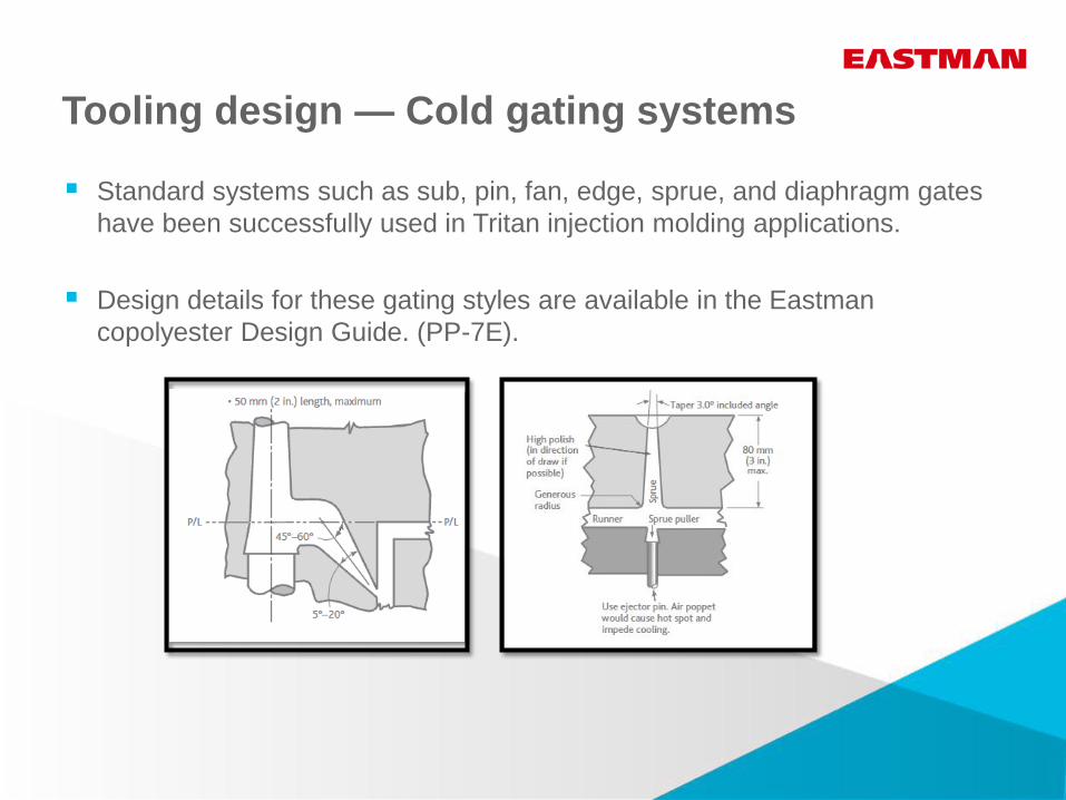
Tooling design — Cold gating systems
Standard systems such as sub, pin, fan, edge, sprue, and diaphragm gates
have been successfully used in Tritan injection molding applications.
Design details for these gating styles are available in the Eastman
copolyester Design Guide. (PP-7E).
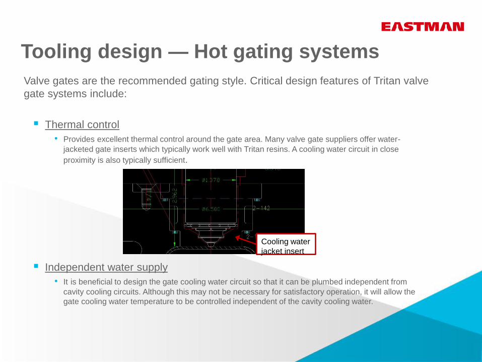
Tooling design — Hot gating systems
Valve gates are the recommended gating style. Critical design features of Tritan valve
gate systems include:
Thermal control
• Provides excellent thermal control around the gate area. Many valve gate suppliers offer water-
jacketed gate inserts which typically work well with Tritan resins. A cooling water circuit in close
proximity is also typically sufficient.
Independent water supply
• It is beneficial to design the gate cooling water circuit so that it can be plumbed independent from
cavity cooling circuits. Although this may not be necessary for satisfactory operation, it will allow the
gate cooling water temperature to be controlled independent of the cavity cooling water.
Cooling water
jacket insert
Tooling design — Hot gating systems,
valve gates
Small parts
• Valve gate diameter: 1 mm is the minimum that should be used.
Designing gates smaller than this can result in excessive pressure losses
through the gate. Extremely small gates can also be difficult to avoid gate
“blush” (hazy appearance around the gate) due to high shear rates.
Large parts
• Valve gate diameter should not exceed 5 mm in diameter.
Valve gate pins in excess of 5 mm become difficult to cool across the face of
the pin. This can result in resin sticking to the face of the pin during ejection,
creating a weak spot on the part, as well as an appearance defect.
Design
• No “holdup” areas
Valve gate designs supplied by hot runner system vendors should not have
any areas in the flow path where resin can hold up and degrade, resulting in
possible appearance defects such as brown streaks.
Tooling design — Hot gating systems
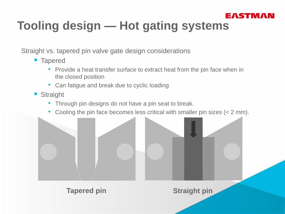
Straight vs. tapered pin valve gate design considerations
Tapered
• Provide a heat transfer surface to extract heat from the pin face when in
the closed position
• Can fatigue and break due to cyclic loading
Straight
• Through pin designs do not have a pin seat to break.
• Cooling the pin face becomes less critical with smaller pin sizes (< 2 mm).
Tapered pin Straight pin
Tooling design — Hot gating systems
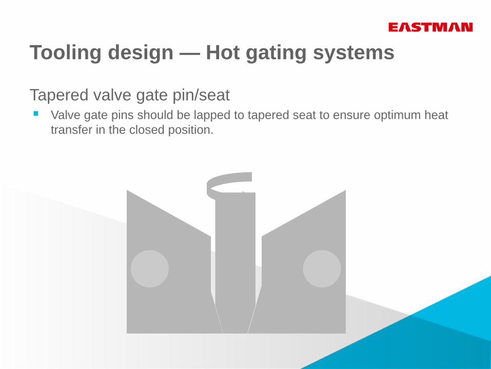
Tapered valve gate pin/seat Valve gate pins should be lapped to tapered seat to ensure optimum heat
transfer in the closed position.
Tooling design — Hot gating systems
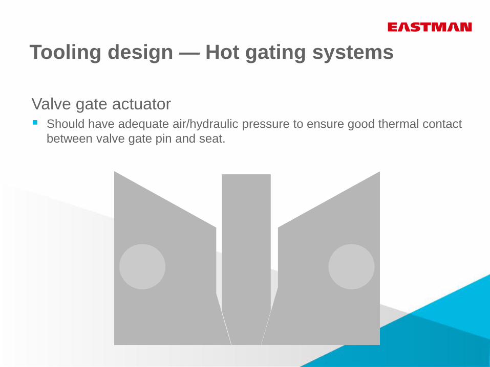
Valve gate actuator Should have adequate air/hydraulic pressure to ensure good thermal contact
between valve gate pin and seat.
Tooling design — Hot gating systems
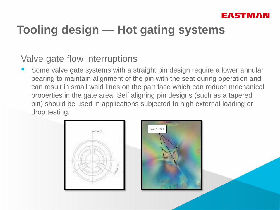
Valve gate flow interruptions Some valve gate systems with a straight pin design require a lower annular
bearing to maintain alignment of the pin with the seat during operation and
can result in small weld lines on the part face which can reduce mechanical
properties in the gate area. Self aligning pin designs (such as a tapered
pin) should be used in applications subjected to high external loading or
drop testing.
Tooling design — Gate cooling
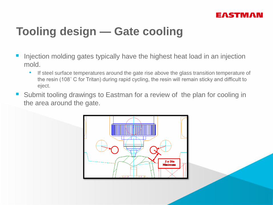
Injection molding gates typically have the highest heat load in an injection
mold. • If steel surface temperatures around the gate rise above the glass transition temperature of
the resin (108˚ C for Tritan) during rapid cycling, the resin will remain sticky and difficult to
eject.
Submit tooling drawings to Eastman for a review of the plan for cooling in
the area around the gate.
Tooling design — Cooling mold materials
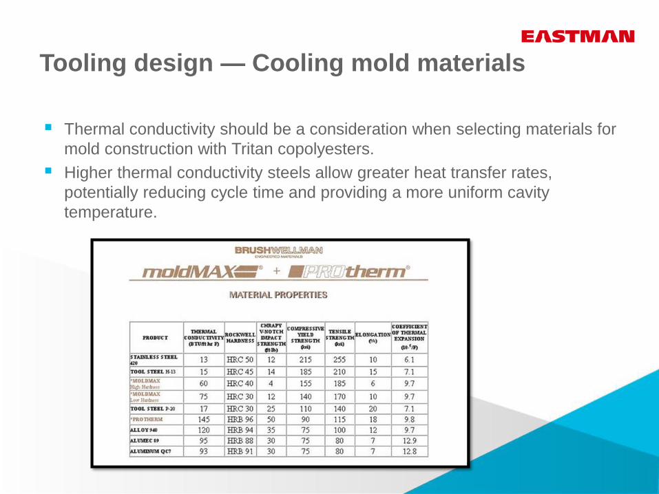
Thermal conductivity should be a consideration when selecting materials for
mold construction with Tritan copolyesters.
Higher thermal conductivity steels allow greater heat transfer rates,
potentially reducing cycle time and providing a more uniform cavity
temperature.
Tooling design — Cooling cavity
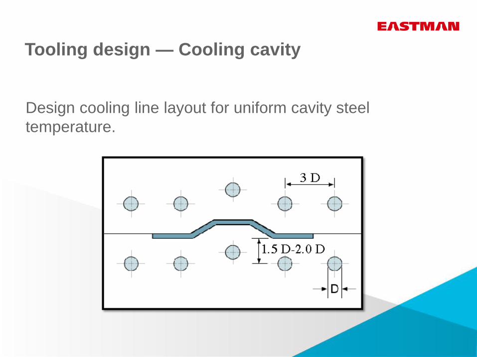
Design cooling line layout for uniform cavity steel
temperature.
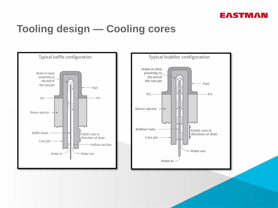
Tooling design — Cooling cores
Tooling design — Venting
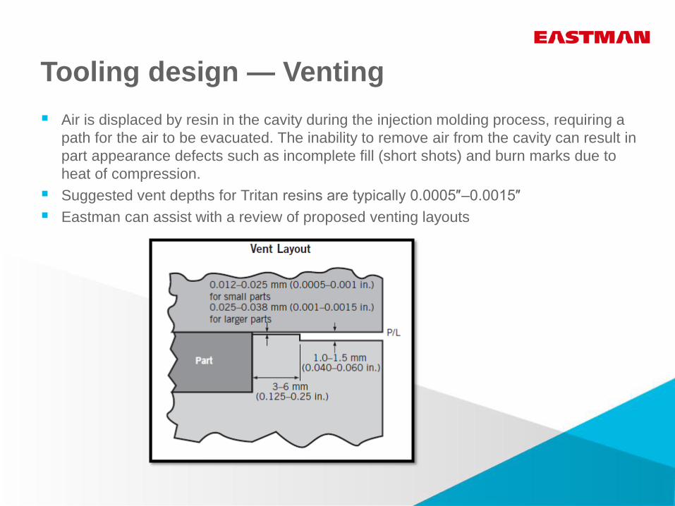
Air is displaced by resin in the cavity during the injection molding process, requiring a
path for the air to be evacuated. The inability to remove air from the cavity can result in
part appearance defects such as incomplete fill (short shots) and burn marks due to
heat of compression.
Suggested vent depths for Tritan resins are typically 0.0005″–0.0015″
Eastman can assist with a review of proposed venting layouts
Tooling design — Ejection
The part is pushed out of the moving half of the injection mold using a mechanical
device such as an ejector pin or stripper ring.
Part design features like long cores or deep ribs with minimal draft can result in high
forces being placed on the molded part during this process.
Tritan resins have a relatively low modulus (more flexible) and yield strength
compared to some competitive transparent resins.
Factors affecting the ability to eject a part successfully:
• Draft
Eastman guidelines for minimum draft on wall surfaces in the direction of draw is 1
degree per side.
• Mold Steel coatings to reduce the coefficient of friction vs. resin
There are several mold steel coatings that have been successfully used to reduce
required ejection forces. Consult with Eastman for a description of these coatings.
• Polish
Polishing mold cavity features in the direction of draw will reduce required ejection
forces.
High cavitation tooling
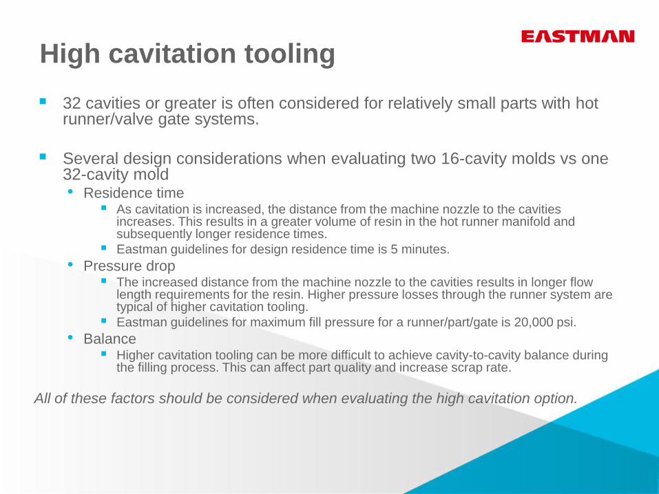
High cavitation tooling
32 cavities or greater is often considered for relatively small parts with hot runner/valve gate systems.
Several design considerations when evaluating two 16-cavity molds vs one 32-cavity mold • Residence time
As cavitation is increased, the distance from the machine nozzle to the cavities increases. This results in a greater volume of resin in the hot runner manifold and subsequently longer residence times.
Eastman guidelines for design residence time is 5 minutes.
• Pressure drop The increased distance from the machine nozzle to the cavities results in longer flow
length requirements for the resin. Higher pressure losses through the runner system are typical of higher cavitation tooling.
Eastman guidelines for maximum fill pressure for a runner/part/gate is 20,000 psi.
• Balance Higher cavitation tooling can be more difficult to achieve cavity-to-cavity balance during
the filling process. This can affect part quality and increase scrap rate.
All of these factors should be considered when evaluating the high cavitation option.
Questions?
Visit TritanMoldIt.com.