PART A: BULK-FLOW AN IS - NASA · Influence of Impeller Shroud Forces on Pump Rotordynamics A...
130
(NASA-CR-1939_I-Pt-A) EULK-FLOW ANALYSIS, PART A Final Report (Texas A&M Univ.) 120 p G3/34 N94-27377 --THRU-- N94-27379 Unclas 0207569 PART A: EP_,._ BULK-FLOW AN _IS , FINAL REPORT NASA Contract No. NAS 8-37821 Dara W. Childs Texas A&M University 10 December 1993 https://ntrs.nasa.gov/search.jsp?R=19940022874 2018-07-07T09:52:05+00:00Z
Transcript of PART A: BULK-FLOW AN IS - NASA · Influence of Impeller Shroud Forces on Pump Rotordynamics A...

(NASA-CR-1939_I-Pt-A) EULK-FLOW
ANALYSIS, PART A Final Report(Texas A&M Univ.) 120 p
G3/34
N94-27377
--THRU--N94-27379
Unclas
0207569
PART A:EP_,._
BULK-FLOW AN _IS ,
FINAL REPORT
NASA Contract No. NAS 8-37821
Dara W. Childs
Texas A&M University
10 December 1993
https://ntrs.nasa.gov/search.jsp?R=19940022874 2018-07-07T09:52:05+00:00Z

| _

PART A: BULK-FLOW ANALYSIS
FINAL REPORT
NASA Contract No. NAS 8.37821
Dara W. Childs
Jordan Professor of Mechanical Engineering
Turbomachinery Laboratory
Texas A&M University
College Station, TX 77843-3254
10 December 1993


q_

=
m
=

(4_._)) /7"
FINAL REPORT
NASA Contract No. NAS8-37821
EXECUTIVE SUMMARY
Introduction
The bulk-flow analysis results for this contract are incorporated in the following publications:
f(a) Childs, D. (1991a), "Fluid-Structure Interaction Forces at Pump-Impeller-
Shroud Surfaces for Axial Vibration Analysis," ASME Trans.; Journal of
Vibration and Acoustics, Vol. 113, pp. 113-115, January 1991
YChitds, D. (1991b), "Centrifugal Acceleration Modes for Incompressible Fluid
in the Leakage Annulus Between a Shrouded Pump Impeller and Its Housing,"
ASME Trans., Journal of Vibration-and Acoustics, Vol. 113, pp. 209-218,
April 1991
__Williams, J. and Childs, D. (1992a), "Influence of Impeller Shroud Forces on
Pump Rotordynamics," ASME _ournal of Vibration and Acoustics, Vol.
113, pp. 509-515, October 1991
/v',,._(e)
Childs, D. (1992b), "Pressure Oscillation in the Leakage Annulus Between a
Shrouded Impeller and Its Housing Due to Impeller-Discharge-Pressure
Disturbances, ASME Trans., Journal of Fluids Engineering,Vol. 114, pp. 61-
67, March 1992
Cao, N. (1993), "Compressibility Effects on Rotor Forces in the Leakage Path
Between a Shrouded Pump Impeller and Its Housing," M.S.M.E. Thesis, Texas
A&M University, August 1993
Computational Fluid Mechanics (CFD) results developed by Dr. Erian Baskharone are
reported separately. Two copies of these publications, were submitted as preliminary final
reports under the terms of this contract and are incorporated in this final reporti:=
The results of this study and the publications aboV:e'can be summarized as follows:-

Impeller Forces for Axial Vibration Analysis
Initial bulk-flow analyses for iml_ellers considered radi_ reaction forces developed by
impellers due to lateral rotor motion Reference (a) above examined the axial reaction forces,
concluding that no resonance exists for axial motion. Methods are presented for calculating
stiffness, damping, and added mass coefficients for axial vibrations of turbopumps.
Centrifugal Acceleration Modes
Prior to this study, Childs (1989) calculated reaction force components for an impeller due to
precession of a pump rotor at nonsynchronous frequencies. His results showed unexpected
peaks in the force components which he ascribed to fluid "resonance", arising from the
centrifugal-acceleration term in the momentum equation. Dr. Brennen at Cal Tech questioned
this terminology, suggesting that the term resonance could only be supported if an analysisconfirmed that the governing system actually had complex eigenvalues at or near the locations
of peak amplitudes. Childs (1991b) cited above, yielded roots and eigenvectors at the
predicted locations, confirming the prior predictions of fluid resonances.
Influence of Impeller Shroud Forces on Pump Rotordynamics
A question presented by the initial predictions that impeller reaction forces could contain
"peaks" was: How should radial and circumferential reaction forces be modeled if they can
not be modeled with stiffness, damping, and added-mass coefficients? Furthermore, what
influence do the predicted peaks have on rotordynamics? Williams and Childs (1992a)
developed linear and nonlinear analysis procedures for incorporating the frequency-dependent
radial and circumferential force coefficients into a rotordynamic analysis. Transient nonlinear
analysis used the predicted reaction forces directly as a function of the instantaneous
normalized precession frequency. Synchronous response due to imbalance proceeds directly,
replacing the radial and circumferential force coefficients with direct and cross-coupled
stiffness coefficients which are a function of running speed. Eigenanalysis is iterative, since
the stiffness coefficients depend on the precession frequency which is in turn def'med by theeigenvalue.
The predicted impeller-force peaks were shown to have a major influence on rotordynamics
for the model considered. However, the results are difficult to generalize to turbomachineryrotordynamics.
Pressure Oscillation ExcitationOf the Flow in an Impeller Shrouded Annulus
The analyses cited above all considered reaction forces due to impeller shroud motion.
Childs (1992b) looked at the separate problem of pressure and velocity predictions in the
annulus due to precessing pressure oscillations at the discharge of the impeller. This analysis
was not aimed at rotordynamics. The impeller is assumed to be spinning but not precessing.

Pressureoscillationfrom the impeller dischargepropagatedown throughthe annulusandoutthe exit wearing-ringseal. The analysisshowedthatmultiple sharpresonancescould beexcitedin the annulusandthat they typically resultedin peakpressureoscillationsat or nearthe exit wearing-ringseal. Theseresultssuggesteda possibleexplanationfor the internal-cooling problemfor the KEL-F exit sealsof the SSME-HPFTP.However,the applicability oftheanalysiswas limited becausean incompressible-flowmodelwasused.
Compressibility Effects on Rotordynamics and Leakage and Pressure in an Impeller
Annulus
Nhai's (1993) thesis extended previous models by incorporating fluid compressibility. Nhai
uses a barotropic model for which the viscosity and density are functions of the pressure
(only). Adding compressibility to the model means that acoustic modes can be generated in
addition to the "centrifugal-accelerations" modes which were present in earlier analyses.
Acoustic analysis normally discards perturbation terms which are included in Nhai's general
perturbation analysis.
Nhai used the HPFTP first stage impeller for his analysis. He analyzed the exit wearing-ring
seal leakage-AP relationship using a code developed by Morrison et al. (1983). Fluid
properties were modeled via an NBS code, McCarthy et al. (1986).
Nhai examined the influence of compressibility on both rotordynamic characteristics of pumps
and pressure and flow oscillations within the annulus due to pressure perturbations of the
impeller exit. Concerning rotordynamic-response characteristics, Nhai's analysis sought to
answer the following basic questions:
(a) What influence does compressibility have on the centrifugal-acceleration modes
predicted by earlier analyses?
(b) What "acoustic" modes are predicted due to fluid compressibility?
The answers provided are as follows:
(a) Compressibility has a negligible influence on centrifugal-acceleration modes.The result with and without compressibility are basically the same.
(b) Fluid compressibility yields acoustic modes, with the lowest mode appearing at
about twelve times running speed. This mode would be excited by rotor
precession.
Concerning pressure oscillations within the leakage annulus, Nhai used a precessing pressure
wave at the pump impeller exit for excitation with n diametral modes. Following Bolleter
(1988), n=nl (impeller vanes) - n2 (diffuser vanes) = 24-13=11. Nhai's analysis predicts sharp
peaks at precessional frequencies which are 6.5 and 7.8 times running speed. These modes
give predicted amplification factors from impeller discharge to the exit seal of the annulus

(inlet sealof the impeller) of 7.5 and 17.8. Eithermodecouldreasonablyexplain the internalmelting observedin theHPFTPseals. The difficulty is thatno excitationfrequencyispredictedby existingtheoriesneartheseresonantfrequencies.Bolleter predictsexcitationfrequenciesat multiplesof _ = n_c0/nwherec0is therunning speed. Table2 (page38) ofNhai's thesisshowsnoexcitationfrequenciesat or neartheresonantfrequencies.
To bebrief, thepresentanalysisonly providesa plausibleexplanationfor themelting-sealsituation,if the impellerprovidestherequiredexcitationfrequencies,andtestingwould benecessaryto confirm their presenceor absence.
REFERENCES
Bolleter, U., (1988), "Blade Passage Tones of Centrifugal Pumps," Vibrations, Vol. 4, pp. 8-13, September. o
Childs, D. W., (1989), "Fluid-Structure Interaction Forces at Pump-Impeller-Shroud Surface
for Rotordynamic Calculations," ASME Trans., Journal of Vibrations, Acoustics, Stress, andReliability in Design,Vol. 111, pp. 216-225, July.
McCarthy, R.D., (1986), "Thermophysical Properties of Fluids, MIPROPS 86," NBS Standard
Reference Data Base 12, Thermophysics Division, Center for Chemical Engineering, NationalBureau of Standards, Boulder, Colorado.
Morrison, G.L., Rhode, D.L., Kogan, K.C., Chi, D., and Demco, J., (1983) "Labyrinth Seals
for Incompressible Flow - Final Report," G.C. Marshall Space Flight Center, MSFC,Alabama, 35812, Report Number SEAL-4-83, November.

_-, pi"
=
F ¸ _T
:--_--


Reprinted from January 1991, Vol. 113, Journal of Vibration and Acoustics
D. W. ChildsTurbomachineryLaboratories,
MechanicalEngineeringDepartment,Texas A&M University,
College Station, TX 77843
Fluid-StructureInteractionForcesat Pump-Impeller-ShroudSurfacesfor AxialVibrationAnalysisSolutions are presented for the dynamic axial forces developed by pump-impeller-
shroud surfaces. A bulk-flow model of the leakage path between the impeller and
the housing is used for the analysis consisting of the path.momentum, circumfer-
ential-momentum, and continuity equations. Shear stresses at the impeller and hous-
ing surfaces are modeled according to Hirs" turbulent lubrication model. The
governing equations were developed earlier to examine lateral rotordynamic forces
developed by impellers.A perturbation expansion of the governing equations in the eccentricity ratio
yields a set of zeroth and first.order governing equations. The zeroth-order equations
define the leakage rate, velocity distributions, and the pressure distribution for acentered impeller position. The first-order equations define the perturbations in the
velocity and pressure distributions due to axial motion of the impeller. Integration
of the perturbed pressure and shear-stress distribution acting on the rotor yields the
reaction forces acting on the impeller face.Calculated results yield predictions of resonance peaks of the fluid within the
annulus formed by the impeller shroud and housing. Centrifugal acceleration terms
in the path-momentum equation are the physical origin of these unexpected pre-dictions. For normalized tangential velocities at the inlet to the annulus,
Ueo( O) = Ueo(O)/RM of 0.5, the phenomenon is relatively minor. As ueo( O) is in-creased to O. 7, sharper peaks are predicted. The fluid modes are well damped in all
cases.Numerical results are presented for a double-suction single-stage pump which
indicate that the direct stiffness of the perturbed impeller shroud forces are negligible.
Small but appreciable added-mass and damping terms are deueloped which have a
modest influence on damping and peak-amplitude excitation frequency. The forces
only became important for pumps with very low axial natural frequencies in com-
parison to the running speed, viz., ten percent of the running speed or lower.
Introduction
Figure 1 illustrates an impeller stage of a multistage cen-trifugal pump. Leakage along the front side of the impeller,from impeller discharge to inlet, is restricted by a wear-ringseal, while leakage along the back side is restricted by eitheran interstage seal or a balance-discharge seal. The axial thruston the impeller is obviously of interest for structural integrityof the pump and several investigators have presented analysesand test results for the thrust versus various impeller param-
eters; Thomae and Stucki (1970), Lobanoff and Ross (1985).Impellers are sometimes used directly as thrust-balancing ele-
ments; e.g., the main impeller of the Space Shuttle Main Engine(SSME) High Pressure Oxygen Turbopump (HPOTP) is ofdouble,suction-entry design, and orifices at the inlet and exit
of the leakage path create the principal axial-thrust-balancefor the rotor. The leakage-path for the back side of the High
Contributed by the Technical Committee on Vibration and Sound for pub-lication in the JOtTP_ALor VmP_ATtONA_D ACOUSTICS.Manuscript receivedJanuary 1990.
Pressure Fuel Turbopump (HPFTP) is also used for axial thrust
balance.From an axial vibration viewpoint, the change in the axial
thrust of an impeller which is used for axial-thrust balance isnormally modeled by a stiffness and damping coefficient, i.e.,
Fz= -KZ,-CZ, (l)
where Z, is the axial change in position. The stiffness coefficientK is the local slope in the thrust versus axial position curveand is nominally constant around the equilibrium position. Inthe SSME turbopumps, the stiffness of the pump housing is
used in series with the slope of the thrust-axial-position curveto calculate'K. Damping primarily arises due to flow through
orifice restrictions.An implicit assumption involved in the model of equation
(1) is that the natural frequencies of the fluid in the leakagepath are much higher than the pump's running speed or theaxial vibration frequencies of the rotor. From a conventional

IMPELLER SHROUD
WEAR RING _ SURFACES 7
"." ,-I ERSrAGE
Fig. 1 Impeller stage
acoustics viewpoint, this is certainly the case; however. Child's0987, 1989) analysis of incompressible flow in the leakage
path revealed resonances associated with the centrifugal ac-celeration of the inwardly-flowing fluid. The present investi-
gation of the dynamic axial thrust developed by the pumpimpeller shroud is stimulated by the 198Tanalysis and uses thesame flow model.
Geometry and Kinematics
Figure I illustrates the annular leakage paths along the front
and back sides of a typical shrouded impeller of a multistagecentrifugal pump. The present discussion concentrates on the
Nomenclature
a = nondimensional steady-state amplitude due to
harmonic excitation,
defined by equation(39)
A ts,A_,A 3s _- coefficients introduced
Ale_2e,A3e in equation (18) and
defined in the appendix
Ca, = discharge coefficientfor the exit wear-ringseal, introduced in
equation (13)
Cs = initial (s= 0) clearance
tL)f= f//o_ = dimensionless axial ex-
citation frequencyf, or2,f3 = dimensionless solution
coefficients introduced
in equation (25)fk,fc = dimensionless force
coefficients introduced
in equation (31)F0 = nominal axial reaction
force defined by equa-
tion (30)
Fz = axial reaction force (r-)h = H/C, = nondimensionalized
clearance
H = clearance between im-
peller shroud and
housing (L)
Fig. 3
I....__f -s _¢?l.__Jr .... J J t-
Y
XFig. 2 Impeller surface geometry
R(s)
-- 0
Local attitude angle of impeller surface
flow and pressure fields within the forward annulus; however,the analysis also applies to the rear annulus. As illustrated in
Fig. 2, the outer surface of the impeller is a surface of revo-
lution formed by rotating the curve R = R(Z) about the Z axis.
A point on the surface may be located by the coordinates
Z,R(Z),O. The length along the curve R(Z) from the initial
L_ = leakage-path length,
defined by equation
(3), (L) to harmonic excitation,p = P/p V_ = nondimensionalized defined by equation
static fluid pressure (39)
P = fluid static pressure _ = perturbation coefficient
(F/L2) w = pump running speedr=R/R i = nondimensionalized ra- (T-_)
dial coordinate_. = pump axial natural fre-
R = radial coordinate (L) quency (T-i)
R_ = initial (s= o) radius (L) _. = _o./w = dimensionless pump
R, = 2HUs/v = path-velocity Reynolds axial natural frequencynumber tl = axial excitation fre-
s=S/L_ = nondimensionalized quency (T-_)
path length p = fluid density (M/L 3)S = path coordinate intro- 0 = circumferential coordi-
duced in equation (2), hate
(L) a, as = normalized friction
T=L/V_ = representative transit factors, defined bytime for fluid travers- equation (15)
ing the leakage path r=o_t = nondimensionalized(7) time
us=U/V, = nondimensionalized // = entrance-loss coeffi-
path fluid velocity cient introduced in
ue = Ue/R,_ = nondimensionalized equation (1 l)circumferential fluid _ = A/Ci -- nondimensionalized ax.
velocity ial impeller displace-V_ = initial (s = 0) fluid ve- ment
locity ,a = axial impeller displace-
_b = steady-state phase due ment (L)

pointRi,Z, to an arbitrary point R,Z is denoted by S and
defined by
1 + + du (2)S= z, k_'-_, ] = e,
In the equations which follow, the path coordinate S and
angular coordinate 0 are used as independent spatial variables.The coordinates Z,R defining the impeller surface are expressed
as parametric functions of S, i.e., Z(S), R(S). The length of
the leakage path along the impeller face is defined by
L, = ,)z_ + -_ du (3)
Trigonometric functions of the angle 7, illustrated in Fig.
3, are defined as follows
dR dZ dR
tan'¢ = - _-_, cosy = _-_, sin7 = - _-_ (4)
The clearance between the impeller and the housing is denoted
as H(S,O,t), with the time dependency introduced by impellermotion. In the centered position, the clearance function de-
pends only on S and is denoted by Ho(S). Displacement of theimpeller in the Z direction by the differential A yields
• dR
H(S,O,t) = Ho(S) - A(t)sin7 = Ho(S)'+ A(t d)-_S (5)
Governing Equations
Returning to Fig. 2, the path coordinate S and circumfer-ential coordinate RO are used to locate a fluid differential
element of thickness H(S,O,t). From Childs (1987), the con-
tinuity equation can be stated
+ v,=0
where Us and Ue are the path and circumferential bulk-velocity
components, respectively. Also from Childs (1987), the pathand circumferential momentum equations are stated
aP ,,U_dR /3U, OU, Ue OU, \- - +"o÷",,+"" +v; +
HaP /aUo auo Ue auo . ueu, ae\-- -_ _)--_ = 7 ,s + I",r + P H L W + - _ "-_ + "_ Cls + ---R- a-S)
Following Hits' approach (1973), the wall shear-stress defi-
nitions in these equations can be stated
rm'+|
_ ms
rss=--fpU_Rs [1 + (Ue/U,)2] -'-_
mr+ I
nr , aRmr.r_=--fptJ, , 11 +[(Uo-Ro_)/U, I2I --T-- (6)
m$+l
ns _ - -_u- 1res='-fpUoUr K, l + (VolU_)2l-'S--
mr+l
nr mr
re, ="fpU,(Ue- R,_)R, [ 1+ [(Ue- R,_)/U,I" l-T=
where
R, = 2HU/v (7)
Nondimensionalization and Perturbation Analysis
The governing equations define the bulk-flow velocity com-
ponents (U. Ue) and the pressure P as a function of the co-
ordinates (RO, S) and time, t. They are convenientlynondimensionalized by introducing the following variables
u,= U, IVi, uo= UelR_o, p=PloV_
h = H/C. s = S/Ls, r = R/Ri (8)
r = o_t, b = Vi/R_, T= L/V,
The objective of the present analysis is to examine the changesin (u,, ue, P) due to changes in the clearance function h(O,s,t)
caused by small axial motion of the impeller within its housing.
To this end, the governing equations are expanded in the per-
turbation variables
Us=Uso+eUsl, h=ho+_ht
ue=Uoo+_Uel, p=po+_pl (9)
where _=e/C_ is the perturbation parameter. The following
equations result:
Zeroth-Order Equations
(a) Path-Momentum Equation
dPo lfdr\u_o [______) l dho ldrTu2ds rL-_s)'-'_ + hods 7dsJ ,o=0 (10o)
(b) Circumferential-Momentum Equation
duoo Ueo dr___s +_;. __ + [o,(Uoo_ r) + orUoo]/2 =O (10b)
(c) Continuity Equation
rhou_o = 1 (10c)
dusoThe continuity equation has been used to eliminate _ from
equation (10a). The mohaentum equations define the pressureand velocity distributions for a centered impeller position. They
are coupled and nonlinear and must be solved iteratively. Theinitial condition for Ueo(O) is obtained from the exit flow con-dition of the impeller. The inlet and discharge pressure of the
impeller are known and serve, respectively, as the exit (P,) and
supply (P_) pressures for the leakage flow along the impellerface. The inlet condition for Po is obtained from the inlet
relationship
Ps- Po(O,O,t) = p(i + OU2o(O,O,t)/2 (l l)
From this relationship, the zeroth-order pressure relationship
is
po(O) = Pr/p V_ - (1 + _)U:so(O)/2 (12)
The wear-ring seal at the leakage-path exit also provides a
restriction, yielding a relationship of the form
P(Ls,O,t) - P, = 2 Ca, U_,(L,,O, t) (13)
First-Order Equations
(a) Path-Momentum Equation
_s L or r aO u,o
(14a)
(b) Circumferential-Momentum Equation
R i _ _ + llolA_ + 14slA3e
[ ..Ou,t -Ueoau,, au_,]+ +..o- Tj=hv ,e (14b)
(c) Continuity Equation
¢9U,, oat Oue, [1 dr 1 d_.) =h,..o.dho I / ah, oad_,oah,+.odh,
+-E-o + W.)

62
t DIMENSIONS INMILLIMETERS.
175
Fig. 4 Nominal configuration of test Impeller
Most of the parameters of these equations are defined in Ap-pendix A. The quantities os and orare defined by
-,= (L/Ho)X,, a, = (L/Ho)h, (15)
where Xs and X, are dimensionless stator and rotor frictionfactors defined by
ms÷]
Xs = nsR_[l + (uoo/bu.o) 2] 2
lwr+ ]
X,=nrR_o'[ 1 + [(ueo-r)/buso] 2] 2
From equations (5) and (8), the perturbation clearance func-tion is
hi _ R(__)dr 6= A__=; ds' Ci (16)
Hence,
ah, (R_,%d=, ah,as-;tZ-d o0-°
First-Order Equation Solutions. For axial excitation, the 0
partial derivatives of equations (14) are eliminated. The time
variation can be eliminated by assuming the following har-monic solutions for the clearance excitation
6= 6oe m' = ¢_0eg" (17)
and dependent variables
Pi =Pte if', usl = ftsledt>, ue] = fte,e df" (18)where
f= 9Ao, _t = r (19)
Note that _bl, tJs_ , and fie= are now complex variables. Sub-stitution into equations (14) yields
where
and
LPl J t.Pi.) l
[A]= A_lu_o (Aze+jfT)lu,o
L A 3, - u_oB + JI_ T A zs
"' I )
14 dr - flT dr l
(20)
(21)
(22)
F2 Uso d2___ I dhodr _ B=l dr I dho (23)-ho ho "_s d__)' r ds+ ho ds
The following three boundary conditions are specified for thesolution of equation (20):
(a) The entrance-perturbation, circumferential velocity iszero, i.e.,
zie,(0) = 0 (24a)
(b) The entrance loss at the seal entrance is defined by equa-tion (11), and the corresponding perturbation-variable rela-tionship is
Pl(0) = - (1 + _)iTsl(0 ) (24b)
(c) The relationship at the exit is provided by equation (13)and yields the following perturbation relationship
Journal of Vibration and Acoustics JANUARY lt1_1 Vnl 11"1 ! 111

1,i
• 1t /
.1 ueo (0) = 0.5 // /
i t /
(o) : o.6.......
u0o(0) = 0.7 .... " /
J /
/i /
t" /s t"
.04 ,'" /I" /
/ /s r s"
/r/,/
.02 / ""! S /s /
j." _-
0. .25 .'5' '. "/,5 1. 1. 1.5 1.75 2. 2.2b 2.5
Fig. 5 f_versus l= W_ for um = 0.5, 0.6, and 0.7
.08
.O6
0.
-.01
-.02
___-.03
-.04
-.05
-.o_
/i/int
//
/,/t
s/
ueo(O ) = 0.5_I
/ ueo(O) = o.6 ........I
/ ueo(0) = 0.7 ....
' '.25 ' ' .5 ' .75 I. 1.25 1.5 1.75 2. 2.25 2.5
Fig. 6 fc versus I: fl/- Ior u_ = 0.5, 0.6, and 0.7
Table 1 Zaroth.ordar.solutl0n results; C,: 3.5 mm =
-.iolo ioCa, 1.655 1.690 1.731
eh (kg/,,zc) 4.784 4.391 3.973
rox 10-'(N) 2.25 2.15 2.04
.D,(I) = C_,.,so(l)u,,(l) (24c)
The value for C_ depends on the wear-ring sea] geometry.Solution of equation (20) for the boundary conditions of equa-
tions (24) is relatively straightforward using a transition-matrix
approach (Meirovitch, 1986). The solution can be stated
.,,:: I:- I:p,j l,.f3, + if3,.)
1121Vol 113, JANUARY 1991
Table 2
_m
0.5
0.6
0.7
Asymptotic coefficients from Figs. 5 and @
/('o x I0 -( Ma
,Vim X0
.648 5.61
6.05 5.63
13.6 5.68
Cox 10 =
Kg
.809
.911
1.05
Reaction Force. From Fig. 4, the axial differential force
component on a differential-impeller surface area can be stated
dFz = - (Psin'y + 1._os.y)RdOdS (26)
The zeroth and first-order force components are obtained by
substituting for P and r,_ in equation (26). From equation (6),
the perturbation shear stresses can be stated
vs,, = P _(Bs,u,, + B_uo, + B,3h,) (27)
Transactions of the ASME

The coefficients of these equations are defined in the appendix•The zeroth and first-order forces are defined by
Fz°= 2xR2i [Zrjo zdr t dz
and
f zI = f Zlk+ JFz'c = Fo(/'k+ Jffc)_owhere
2 2 '2Fo = xRiAP= rRi Cap V;2 CtF dr
+ ': "(-_) B.'_ss]rds
2 I dr L Lffc=-cdS£If3S_ss+(_i)Bstfls+(-_i)Bszfz_]rds
lO[ ,:
uoo(O)=0.5_(28) _
7 :s,
uoo(O} "0'7 ....
(29) 5_- Bk .o Imp*ller Fores---- :I:'>IZ,I//_I
_','(3o) 4_ I(,':
_/;
• 1 •2 .3 .4 •5
f=_/u
,6 .7 .8 ._9
Numerical Results. Figure 4 illustrates the pump-impellerand shroud geometry used by Bolleter et al. (1987) in their testprogram for radial force coefficients. Their pump uses a vaneddiffuser. Their tests were at best efficiency point (BEP) withthe pump running at 2000 rpm, while developing 68m of headand 130 l/sec of flow rate. The impeller has seven blades andan impeller exit angle of 22.5 deg. The test fluid is water at80"F. For the present study, AP across the impeller is assumedto be 70 percent of the total head rise of the stage. Based onpitot-tube measurements, impeller exit tangential velocity isabout 50 percent of the impeller discharge surface velocity;hence, ueo(0) = 0.5.
Both walls of the annulus are assumed to be smooth andrepresented by Yamada's (1962) test data; mr= ms = -0.25,nr=ns=0.079. The inlet loss for the annulus, _, is assumedto be 0.1. The discharge coefficient for the seal is calculatediteratively as follows. With an assumed Cde, equations (10),(11), and (12) were used to calculate the leakage through theimpeller annulus and the pressure and tangential-velocity up-stream of the seal. The seal is then analyzed (with the sameequations) using the calculated seal inlet pressure and tangen-tial velocity to determine leakage and Cd,. The iteration con-tinues until the leakage predictions for the exit seal and theimpeller annulus agree. Table 1 provides zeroth-order solu-tions.
Figures 5 and 6 illustrate f, and fc versus f for u0o(0) = 0.5,0.6, and 0.7. The u_o(0) = 0.5 curves are comparatively smooth;the ue0(0)= 0.6, 0.7 curves show evidence of fluid resonancessimilar to those obtained earlier by Childs (1987). Specifically,in the absence of fluid resonances, the expected results for f,would be a parabola without the predicted fluctuation in theneighborhood off=0.25. Further, the expected result for rewould be a constant without the low-frequency fluctuations.
The functions fk, fc are nondimensionalized frequency-de-pendent stiffness and damping coefficients. To develop a phys-ical model for the axial reaction forces defined by these curves,the fkb0 curves will be reviewed first. All of the fk curvesdemonstrate a quadratic asymptote with the following fre-quency-domain model
fk,(/) = - £ + A4Je, (32)
which implies the time-domain reaction-force model
Fk,, = - (K,.Z, + M.Z,,) (33)where
I(. = l(Fo/ C. M¢ = h_.fFo/Ct._ (34)
The physic.m] coefficients obtained from a curve fit of theasymptotic solutions in Fig. 5 yieldthe physical coefficientsof Table 2.
-20
-40
-60
-80
.-.>-100
-120 uoe(O) = 0.5
Uoo(O)-0.6 ........-140 _x
uoo{O) = 0.7 .... _,,_
-160 No Izp,iZer rorc=---- "t¢_"__z_
-1800__=-_z-,-.,__, , . . ,• .I .2 ._ ._ '.'5 .s .7 .8 .9Fig. 7 Amplitude and phase of a versus f for ;:,,, = ,_./_ = 0.5; u_0 : 0.5,0.6, and 0.7
The stiffness values are negligibly small in comparison tothe axial stiffness which would center the pump rotor eitherthrough a thrust bearing or balance-piston arrangements. Themass coefficient is small but appreciable in comparison to theimpeller mass. This "added mass" contribution to the impellerrotor has not previously been accounted for in axial vibrationanalyses of pumps.
Thef_ curves of Fig, 6 can be viewed as nondimensionalizedfrequency-dependent damping coefficients. The asymptoticbehavior of these curves (for high values of,/) shows an un-expected, approximately-linear, increase in damping with in-creasing frequency. The asymptotic results are curvefitted bythe linear model
fc(J) = 1_o- C'f (35)
The linear dependence offc on C yields the time-domain re-action-force model
F,.,,= -C,,_,,Z,, fl,,= IZ.,./Z,I '" (36)where
Co= dFJ C_Z
Values of C, are provided in Table 2. Physically meaningfulvalues for damping are obtained by multiplying Ca by 12,e.g.,the nominal damping value for fl = co= 209 rd/sec is about 209N sec/m (1.2 ib sec/in) which is significant.
t .....

l0I9i
8
7
6
Ts
4
3
2
I
u0o(0) = 0.5
u0o(0] = 0.6........ Ji
u0o(0) - 0.7.... /,i,/
1=fl/_
i
\,\
1.75 2. ' ' 2.'25' ' "2'.5
0
-20
-40
-60
-8O
-Ioo
L-12o _e°(°)=o.s_ i
I ........-140 'k
uoo(0): 0.7....
-160 1 No Impeller Force ----
• .2s .s .n L _.2s_.s _.TSi.'"L'2_Z5
Fig. 8 Amplitude and phase ol a versus f for ,'-,,: ,,,,h,): 1.5; use: 0.5,0.6, and 0.7
The physical example used to demonstrate the solution ofequation (39) is a double-suction single-stage pump with the
impeller of Fig. 4 and the following physical data:
Mzo = 100 kg, _'=0.05, (_ = 2000 rpm= 209 rd/sec
With a double-suction design, the reaction force from the
impeller face is doubled. Figures 7 and 8 illustrate solutions
to equation (39) for _, = 0.5 and 1.5 times the running speed
for no impeller forces and impeller forces corresponding to
u00(0)=0.5, 0.6, and 0.7. The magnitude and phase of a are
presented and demonstrate that the impeller forces provide amodest amount of additional damping and slightly displace
the peak-amplitude-frequency location. Although not pre-sented here, the impeller forces did cause significant changes
in the steady state response when &, was reduced to unreal-
istically low values on the order of 0. I.
Summary and Conclusions
An analysis has been developed and predictions presented
for the axial forces developed on a pump impeller shroud. The
force coefficients are reduced to frequency-dependent stiffness
and damping coefficients. Fluid resonances are evident in theseresults comparable to the rotordynamic-coefficient analysis
results of Chiids (1987). The asymptotic expansion of these
coefficients yield negligible stiffness values and small but ap-
preciable added mass and damping coefficients.Frequency-response analysis o f a double-suction single-stage
pump impeller indicates that the impeller shroud forces providea little additional damping and can modestly move the damped
natural frequency of the system for pumps with axial natural
frequencies on the order of 0.5 to 1.5 times the running speed.
The impeller-shroud •forces can only become really significantfor natural frequencies that are much lower than the running
speed, viz., one tenth of the running speed or lower.
Acknowledgment
The results reported herein were funded in part by NASA
Marshall Space Flight Center, NASA Contract NAS 8-37821;Contract Monitor: James Cannon.
Modeling Annular Forces for Axial-Vibration Analysis. Thetransient model for axial vibrations, including the impeller
forces, can be stated
MjZ,+(Cw_Fc)Z,+(Kw_Fk)Z =F, tt ) (37)
where Mw, Czo, and Kzo are the nominal mass, damping, andstiffness coefficients, F,(t) is the external excitation force, and
Fc(/'o) = fc(fo)FJ C_; Fk(fo)= ftOro)FJ C, (38)
f° = fi°l_
The model of equation (2) has moved the impeller-shroud
reaction force from the right-hand side of the equation to the
left-hand side of the equation. The force is now modeled as
frequency-dependent stiffness and damping coefficients, whichcombine directly with the nominal, mechanical, stiffness and
damping coefficients.For an external harmonic excitation force of the form
Fe = F_ "_a*, the steady-state solution Z,_= Ae/a' is defined by
a = Ia I_ = A I(FeolKw)
= _/{ [_(1 - jTk) _./-21 +jf&,(2_- .f¢&.) ] (39)
where
J, = Kzo/ M_o; 2_, = Czo/ Mzo (40)
; f_ I'Fo_ - fk/'Fo\
114 I Vol. 113, JANUARY 1991
ReferencesBolleter, U., Wyss, A., Wehe, I., and Sturchler, R., 1987, "Measurement of
Hydrodynamic Matrices of Boiler Feed Pump Impellers," ASME JOURNALorVIBRATIONS, ST'IKES$, AND RE_I]LrrY IN DESIGN, Vol. 10_, pp. 144-151.
Childs, D. W., 1987, "Fluid Structure Interaction Forces at Pump-lmpeller-ShroudSurfaces for Rotordynamic Calculations," Rotating Machinery Dynam-ics, Vol. 2, ASME, pp. 581-593.
Childs, D. W., 1989, "Fluid Structure Interaction Forces at Pump-lmpeller-Shroud Surfaces for Rotordynamic Calculations," ASME JovtsAt or VIne-"nON,Acous.ncs,ST_JS, ANDR_tt_o.rrY tN DESIGN,VOI. ! Il, pp. 216-225.
Lobanoff, V. S., and Ross, R. K., 1985, Centr_'ugal Pumps, Design and
Applications, Gulf Publishing.Meirovitch, L., 1985, Introduction to Dynamics and Control, J. Wiley.Thomae, H., and Stucki, R., 1970, "Axial Thrust in Centrifugal Pumps,"
Sulzer Technical Review, No. 3.Yamada, Y., 1962, "Resistance of Flow Through an Annulus with an Inner
Rotating Cylinder," Bull. JSME, Vol. 5, No. 18, pp. 302-310.
APPENDIX A
Perturbation Coefficients
A,s= [a_l - ms) + o,(! - mr)]U_o/2ho
2ueodr/l:Azs= --'7- ds + [a,(mr + 1)/9o+ os(ms + l)f3t]uw/2
duso
A_ = -_s + [(2 + mr)o, + (2 + ms)as]uw/2
- [(1 + mr)o_o(Ueo- r) + (l + ms).:lueol/2
2,4 le = uw[( 1 - mr)(uoo- r)o, + (1 - ms)U6oOsl/ho
Transactions of the ASME

2A2a = U,o(O, + a s) + o,(mr + l)(U_o - r)B o
+ o,(ms + l)ueoBI + 2_ °
dr
ds
2A _ = a,(ueo - r)[mr- (1 + mr)f3o(ue o - r)/ Uso]
+ osUoo[mS- (1 + ms)Bluoo/uso]
ao = (Uoo - r)/b_uso| 1 + [(uoo - r)/buso] 2 ]
Ot = uoo/b2uso[1 + (uoo/buso) 2]
rra Perturbation Coefficients
Bet = hal + mr)(ueo- r)[l - Bo(Ueo - r)/u,o]/2b
Be2 = )_rIuso + (1 + mr)(Uoo - r)Bo]/2b
Bo3 -- k,mr(uoo - r)Uso/2bh o
r,_ Perturbation Coefficients
Bsi = X,[(2 + mr)u,o- (1 + mr)Bo(ueo-r)/2]
B a = X_(l + mr)BoU_o/2
Bs3 = h,mru_o/2ho

r_C_
,_ j_l.
_ ± ::

rr _
= =

Reprinted from April 1991, VoI. 113, Journal of Vibration and Acoustics
D. W. ChildsTurbomachineryLaboratories,
MechanicalEngineeringDepartment,Texas A&M University,
CollegeStation, TX 77843
Centrifugal-AccelerationModes forIncompressibleFluid in theLeakage Annulus Between aShrouded Pump Impeller and ItsHousing
An analysis is presented for the perturbed flow in the leakage path between a
shrouded-pump impeller and its housing. A bulk-flow model is used for the analysis
consisting of the path-momentum, circumferential-momentum, and continuity equa-tions. Shear stress at the impeller and housing surfaces are modeled according to
Hirs' turbulent lubrication model. The governing equations have been used earlier
to examine rotordynamic reaction forces developed by lateral and axial impeller
motion.
A perturbation expansion of the governing equations in the eccentricity ratio
yields a set of zeroth and first-order governing equations, The zeroth-order equations
define the leakage rate, and the velocity and pressure distributions for a centered
impeller position. The first-order equations define the perturbations in the velocity
and pressure distributions due to axial or lateral motion of the impeller. Prior analyses
by the author of the perturbation equation have examined the reaction forces onthe shroud due to rotor motion. These analyses have produced "resonance" phe-
nomena associated with the centrifugal-acceleration body forces in the fluid field.
In the present analysis, an algorithm is developed and demonstrated for calculating
the complex eigenvalues and eigenvectors associated with these resonances. First-
and second-natural-frequency eigensolutions are presented for mode shapes corre-
sponding to lateral excitation. First-natural-frequency eigensolutions are also pre-
sented for mode shapes corresponding to axial excitation.
Introduction
Figure ! illustrates an impeller stage of a multistage cen-trifugal pump. Leakage along the front side of the impeller,from impeller discharge to inlet, is restricted by a wear-ringseal, while leakage along the back side is restricted by either
an interstage seal or a balance-piston discharge seal. The pres-ent analysis considers perturbed flow in the leakage paths be-tween the impeller shroud surface and its housing.
Prior analyses by the author of those annulfi have beenconcerned with lateral (1987, 1989) and axial (1990) reaction
forces developed by the impeller shrouds as a consequence ofimpeller motion. These analyses have been based on "bulk-flow" models which neglect the variation in the dependentvariables across the fluid film. The model consists of the pathand circumferential momentum equations and the continuity
equations.
The analyses cited have yielded force and moment coeffi-
-"_ntributed by the Technical Committee on Vibration and Sound for pub-fication in the JotnusAJ.or VmZ_ATIONANDACourrxcs. Manuscript receivedJanuary 1990.
Joumal of Vibration and Acoustics
cients due to impeller motion but have also predicted "reso-
nance" phenomena, which are caused by the centrifugal-acceleration body forces present in the path momentum equa-
tions. In the present analysis, an algorithm is developed and
demonstrated for calculating the complex eigenvalues and ei-
genvectors associated with the fluid resonances.
Geometry and Kinematics
Figure ! illustrates the annular leakage paths along the frontand back sides of a typical shrouded impeller of a multistagecentrifugal pump. The present discussion concentrates on the
flow and pressure fields within the forward annulus; however,
the analysis also applies to the rear annulus. As illustrated inFig. 2, the outer surface of the impeller is a surface of revo-lution formed by rotating the curve R = R(Z) about the Z axis.A point on the surface may be located by the coordinates Z,
R(Z),O. The length along the curve R(Z) from the initial pointRi, Zi to an arbitrary point R,Z is denoted by S and defined
byP_k;. PA_E DLAr,tK NOT FP,.MEL,
APRIL 1991, Vol. 113 1 209

WEAR RING
SEAL
A
ZMPELLER SHROUD
E
Fig.1 Impellerstage
+kz ) "=I:, 1+ " (1)
In the equations which follow, the path coordinate S andangular coordinate 0 are used as independent spatial variables.
Y
Z
Flg.2
X
Impellersurfacegeometry
The coordinates Z,R defining the impelIer surface are expressedas parametric functions of S, i.e., Z(S),R(S). The length ofthe leakage path along the impeller face is defined by
L. = jz_ 1+ du (2)\dZ/
Trigonometric functions of the angle 3', illustrated in figure 2,are defined as follows
dR dZ dRtan-},= - _-_, cos7 = _-_, sin 7 = - _-_ (3)
The clearance between the impeller and the housing is de-noted as H(S,O,t), with the time dependency introduced byimpeller motion. In the centered position, the clearance func-tion depends only on S and is denoted by Ho(S). Displacement
Nomenclature
Ats,A2s, A3s = Coefficients intro-Ato,Az_,A_ duced in equation L. ffi leakage-path length,
(14) and defined in defined by equationthe appendix (2), (L)
Ca, = discharge coefficient P = P/a V_ = nondimensionalizedfor the exit wear- static fluid pressurering seal, introduced P = fluid static pressurein equation (13) (F/L 2)
Ci = initial (s= 0) radial r = R/Ri = nondimensionalizedclearance (L) radial coordinate
C, = exit seal clearance R = radial coordinate(L) (L)
f= fl/o = dimensionless exci- Ri = initial (s = o) radiustation frequency (L)
f,,fc = nondimensional Rs=2HUJv = path-velocity Rey-stiffness and damp- nolds numbering coefficients for s= S/Ls = nondimensionalizedthe impeller corre- path lengthsponding to axial S = path coordinate in-motion at the non- troduced in equa-dimensional fre- tion (1), (L)quencyf= O/o T= L/I�, = representative
frq, fOq = nondlmensional, ra- transit time for fluiddial, and circumfer- traversing the leak-endal impeller-force age path (7)coefficients corre- us = Us/_ = nondimensionalizedsponding to a circu- path fluid velocitylar orbit at the uo = Ue/R_ ffi nondimensionalizednondimensional fre- circumferential fluidquency f= fl/co velocity
h =H/Q = nondimensionalized _ = initial (s = O) rotorclearance velocity
H = clearance between ct=o+flod = dimensionless corn-impeller shroud and plex eigenvalue forhousing (L) _ _ : fluid mode
210 IVol. 113. APRIL lggl
= perturbation coeffi-cient
co = pump running speed(T-')
fl = excitation frequency(T -l)
p = fluid density (M/L _)0 = circumferential co-
ordinate
O.Os = normalized frictionfactors, defined byequation (15)
T= c0t = nondimensionaliZedtime
/_ = entrance-loss coeffi-cient introduced inequation (l 1)
& = axial impeller dis-placement (L)
o=j'_. = dimensionless realpart of complex ei-genvalue for fluidmode
_" = damping factorfrom complex eigen-value
_0d= _0,_- _.2 = dimensionless imagi-nary part of com-plex eigenvalue forfluid mode (dampednatural frequency)
co.ffi dimensionless un-damped natural fre-quency fromcomplex eigenvalue
Trnne_rti_ne _f lhB &_l_

of the impeller in the X and Y directions obviously causes a
change in the clearance function, as does a change in the axialposition defined by Aft). For small displacements and rotationsof the impeller, the clearance function can be stated
H(S,O,t) = Ho(s) - Xcos0 - Ysin0- Asin7 (4)
Observe in this equation that Ho and sin7 are solely functionsof S, while X, Y, and A are functions only of t.
The clearance function provides the excitation for the re-
action forces developed in earlier analyses. Its importance forthe present study concerns the nature of the assumed solution
in seeking eigen solutions.
Governing Equations
Returning to Fig. 2, the path coordinate S and circumfer-ential coordinate RO are used to locate a fluid differential
element of thickness H(S,O,t). From Childs (1987), the con-
tinuity equation can be stated
_+ a_su,n)+_ _ (uph+ _u,=0 (sa)
where Us and Uo are the path and circumferential bulk-velocity
components, respectively. The path and circumferential mo-
mentum equations are stated
ap . f.l_dR i_ll'au, au, uo at./,.\
(5b)
HaP H[aUe+aUe U6 aue ueU, aR).... -- +_-_u,4R ao "+"+P ,Ti" R R(5c)
Following Hirs' approach (1973), the wall shear-stress deft-: nitions in these equations ran be slated
mJ÷|
MS 2 ms
: _: :, r_,=--_pU_R, [l+(Uo/Us)2] --_i IL E+ i_2 ;Z ' :i ::! _:
i mr+ 1
nr -- mrr..= TaU_R. II + [(U0- R.0)/U.]_lT (6)
ms+l
re,=2PUeU,R_[l+ (Ue/U,)_]2
mr+ 1
nrre, = "_O Us(Ue - Rco)R'_'r[ 1 + [( Ue - R,_)/U,12) -T-
where
R. = 2HUJu (7)
Nondimensionalization and Perturbation Analysis
The governing equations define the bulk-flow velocity com-ponents (Us, Ue) and the pressure P as a function of the co-ordinates (RO,S) and time, t. They are convenientlynondimensionafized by introducing the following variables
us= u,/E, us= Ue/R_, p=P/aV2h = H/C. s= S/Is. •= R/Ri (8)
= _t, b = VJR_, T= L/V 1
The objective of the present analysis is to examine the changes
in (us, ue, P) due to changes in the clearance function h(O, s,
t) caused by small motion of the impeller within its housing.
To this end, the governing equations are expanded in the per-
turbation variables
us=Uso+¢Usl, h=ho+ehl
ue=ueo+¢ue,, p=po+¢pl (9)
were _ =e/C_ is the perturbation parameter. The followingequations result:
Zeroth-Order Equations
(a) Path-Momentum Equations
dPo l/'dr\_o [(._o_ l dh o ,dr] 2 0a, rt, )P+ hods u'°= (lO )
(b) Circumferential-Momentum Equation
dueo Ueo dr
-_ss +-r-_-s+[oXuoo-r)+o_ueo]/2=O (lOb)
(c) Continuity Equation
rhoUso = I (10c)
The quantities os and a, are defined by
% = (L/Ho);_s. o.= (LJHo)h. (II)
where X. and X. are dimensionless stator and rotor friction
factorsdefined by
m$+l
ks= nsR_o [I+ (Uso/bu$o)2] 2
mr+ 1
X, = nrR_o_[ 1 + [(Ueo- r)/ buso] 2 ]--T--
duroThe continuity equation has been used to eliminate _ from
equation (10a). The momentum equations define the pressureand velocity distributions for a centered impeller position. Theyare coupled and nonlinear and must be solved iteratively. Theinitial condition for uso(O) is obtained from the exit flow con-dition of the impeller. The inlet and discharge pressure of the
impeller are known and serve, respectively, as the exit (P,) andsupply (Ps) pressures for the leakage flow along the impellerface. The inlet condition for Po is obtained from the inlet
relationship
Ps - Po(0,O, t) = p(l + li)U_so(O,O,t)/2
From this relationship, the zeroth-order pressure relationshipis
po(O) = Ps/a _- (1 +//)u2_,(0)/2 (12)
The wear-ring seal at the leakage-path exit also provides a
restriction,yieldinga relationshipof the form
O,t) - P,, = _Ca,,U_,(Ls,O,t) (13)P(/-,,,
R(s)
Fig. 3
, O
z(s)Local attitude angle of Impeller surface

First-Order Equations
(a) Path-Momentum Equation
_s +u'lAz_+uslA3s+L Or r (90 us°_-l=hlAls
(14a)
(b) Circumferential-Momentum Equation
b'_R_l _-o + u°lA_+ uslA3°r
r ,.,..Ouot + ,r_eo auel Ouel] (14b)L"77 oo+'° 0sj--h,A,,
(c) Continuity Equation
ausj wT au61 [1 dr 1 dho\
h, ,o.dho1/ ah, oah,+ rah, (14c)+-_o "_S -_o LUS°'_S + r 80 Or /
New coefficients in these equations are defined in AppendixA.
Eigen Solutions Corresponding to Lateral Excitation
The first-order equations (14) define the first-order pertur-bations u_l(s,O,r), uel(s,O,z), and p(s,O,r) i'esulting from theperturbed clearance function hi(r). From equations (4) and
(8), hi can be stated
(hi = ht_(s,r)cosO + hls(s,r)sinO (15)
The 0 dependency of the dependent variables is eliminated byassuming the comparable, separation-of-variable, solution for-mat
u_, = us_ccosO + ust,sinO
uet = U01cCOS0+ uol_sinO (16)
pt =ptccosO +ptjsin0
Substituting into equations (14) and equating like coefficientsof cos0 and sin0 yields six equations in the independent vari-ables s,r. By introducing the complex variables
_l=U_l¢+jusl_, uol=uel_+juets
P_l =Ptc +JPls, h I = hlc +jhts , (17)
these six real equations are reduced to the following three
complex equations in s and r.
(18a)
h/LA-_r _T,) p' + uel/lz0 + _,.%e
L a, + ;h,A,, (lSb)
8usl .o_T /! dr 1 dho\
[u:odho .'.'Tueo] usoOh, o_Tah_(l 8c)
The time dependency of equations (18) is eliminated by as-
suming a harmonic solution of the form
ht = h,oe _', usl = ft.,re if', uo_ = u_te _f', p._ = P _df" ; f = fl/ _ (19)
.4
,3
.2
0
-. I
., 2
-.3
-_."<_.. _ \ u_,o_o)• o._-
\] -'. .._
-I.5 -1 -•5 0 .5 ! 1,5 2 :L5
-I. Z5 -.75 -.]5 .2_ .75 I,_5 1°75 _.25
f =n/_
• 5 CONVENTIONAl. IP[PELL[R
[ 4 U_ 0 ( 0 ) I 0 5 ....
• 3 Uo0{O) ffi 06 --
Ueo{O)l 0.7 ....•2
-.1
-. 3
-. 4
-. 5
-1. '_ -I -.5 0 .5 ! 1.5 Z 2._
r-%
Fig. 4 Nondlmenslonal rotordynamlc force coefficients: (a) tangential-force coefficient, (1_ _dlal-force coetflclent,_
The assumed clearance function h_(t) correspond to circularorbital motion of the impeller at the precession frequency ft.
Substitution from equation (19) into equation (18) yields the
three complex ordinary differential equations in s of the form
+ (20)LPlJ LPi) 3
The parameters qo, g_, g_, and g_ on the right hand side aredefined by Childs (1987). The right hand side is important forthe forced solution but irrelevant for eigenanalysis, which con-cerns the homogeneous solution.
The following three boundary conditions are specified forthe solution of equation (20):
(a) The entrance-perturbation, circumferential velocity iszero, i.e., ...... :
ez(0) = 0 (21 a)
(b) The entrance loss at the seal entrance is defined by equa-tion (12), and the corresponding perturbation-variable rela-tionship is
.b_(O)= - (I + O_,t(0) (21b)
(c) The relationship at the exit is provided by equation (13)and yields the following perturbation relationship
,b,(l) = C,_.U,o(Z)_,,(Z) (21c)
The value for Ca_ depends on the wear-ring seal geometry.Figure 4 illustrates the radial and tangential reaction-force
components for solutions to equation (20) from Childs (1989).Tfi_-fl_ee-sbiiit-ions for eacfiTrarne of the figure correspond
to three inlet tangential velocity ratios U0o(0). If the centrifugal
acceleration term is dropped from the analysis, the foq curve
becomes a straight line and the f,_ curve becomes a parabola,which are the expected solutions for liquid, constant-radius,
annular seals; Chiids and Kim (1985). The sharp deviation
from the expected linear and parabolic solution forms for these
curves in the "resonance" phenomenon cited in the introduc-
tion, and it is eliminated if the centrifugal acceleration term
is dropped• The question of interest here is: "If the solutions

of Fig. 4 arise from a 'resonance' of the fluid, how are theassociated eigenvalues and eigenvectors to be calculated, andwhat do the mode shapes look like?"
The first part of the question is answered by reviewing thesolution approach to equation (20) which was used in gener-ating the results of Fig 4. Following normal transition-matrixapproaches (Meirovitch, 1986), the solution to equation (20)can be stated
Iw(s)l = [6(s)llwo] + Iv(s)]; (w)r=(fi,l, ue_, .hi) (22)
where [(I)] is the transition matrix, (wo) is the vector of initialconditions, and (v) is the particular solution obtained for zeroinitial conditions. [6] is obtained by solving the homogeneousversion of equation (20) three times for the initial conditions(1,0,0), (0,1,0), and (0,0,1). One of the three initial conditionsof equation (22) is given; viz., usl(O) = 0. Equation (21b) pro-vides one relationship between the remaining unknown initialconditions ,bl(O) and usl(O). The final relationship betweenthese variables is obtained by evaluating equation (22) at s = 1to obtain
_,_(1) = (I'.(l)_,l(0) + _]dl)_bl(0) + Vl(l),hi(l) = (I)_i(l)usz(0) + #33(1),61(0) + v3(l), (23)
and substituting into equation (21c). The resulting set of equa-tions for the unknown initial conditions can be stated
1[ (_+ o %o)- c.._.o(I)][_.,(o)]L@_l(l)- Cd,,U,o(1) (.hi(O))
0= [_v,(l)+CdeUso(l)v,(l) 1 (24)
For forced response, the right-hand side is nonzero, and themissing initial conditions are obtained by inverting the coef-ficient matrix.
The resonance peaks in Fig. 4 appear when f is near theimaginary part of the complex eigenvalue. To obtain the ei-genvalue, the harmonic solution of equation (19) is replacedby the general solution format
_, = u,le _, _Uel= _01e_, _l =/)l_
where a is both a complex number and the desired eigenvaiue,Substitution into equations (I 8) yields the following definitionfor the coefficient matrix of equation (20)
.12
./.. .,.1 uOo(O) = 0.5i
o,,c01=0.s....... ../.;:".06 ,'s
.= .06 u6o(O ) 0 7 _;_"
.04 "
.O2o._;';" A
.,_,_,.2_._.................0. .2s .s '._g ,'." _.25 i'.g"i.'75i.' 'i.'2_"?:s
O.
,;t
-,01 ///f_f j
/ l-. 02 ,, :
,' I
I
[
ll B
-.o4 ] "e°(ol =o.5_t
/ ue,(o)= o.6-:......t
-.05 / uoe(0) = 0.7 ....
-'%..2s ".5 .75 _. _.2s 1._ 1.7_ 2. 2.2s 2._f .0/=
Fig. 5 Nondlmenslonal ulal force coefficients: (a) stiffness.force coef.flclent, (b) damping-force coefficient
-.03
[A,] =
B
A _el u,o
A_- ua>B+ fl'T
m
.(aT"J 0
r
.b L_(A_ + J_T)Iu,o -_
,(aTA z_+J"_rU,O 0
(2s)
where
{1 dr 1 dho\B= k; _+_'_), r==(a-jueo/r) (26)
Now, the differential equations and their homogeneous so-lutions ate a function of the desired eigenvalue a, and theeigenvalue is found when the determinant of the coefficientmatrix of equation (24) is zero.
The following approach was used to solve for the complexeigenvalues:(a) An initial value, so, is guessed based on the results of Fig.4; viz., %=O+ffo wherefo yields a peak on the f)¢ curve.(b) The homogeneous version of equation (20) is solved toobtain [(I)], and the determinant
De=(l + _)[_'_3(l)-C,_,U,o(1)]-_l,3](1)+ C_eu,o(l ) (27)
3.55
57
[75
Fig. 6
m62DIMENSIONS INMILLIMETERS.
Nominal configuration of the test Impeller
Joumsl of Vibration and Acoustics APRI L 1991, Vol. 113 1 213

.9
.B
.7
.2
.I
0"0, _ ,'1 '
I
r:
" "", :i/.
• '" 'i]uoo(o) o.= 6..-----. ', \,,. \
uooCo_- o_.---- "--,
.] .3 ., .s .6 .7 .8 .9_.5
180
90
-9O
ue=(O) 0.5--
ueo(O) = 0.6 .......
ueo(O) = 0.7 ....
-%_'.'5.'6"5-.'8 .'9",'.s
Fig. 7(a) u,,(s) flret.natural-frequency elgenvector corresponding to lat-eral excitation; C,=0.36mm
is calculated at ao and al = _[1 +6(1 +j)] to obtain Deo and
De1; 6 is a small parameter.(c) The secant rule is then used to calculate the next estimateeq and Dez and subsequent a;'s and De_'s until convergence isachieved.The eigenvalues are obtained by setting
=}sl(O)=l, /_1(0)=(1+_), =}el(O)=O
and evaluating equation (22)
{w(s)i = [_(s,_)]I _o) }
over s_[O,l].
Eigen Solutions Corresponding to Axial Excitation
For axial excitation, the perturbed clearance function hm(T)is defined from equations (4) and (8) to be
A(r)I'R_ dr
This excitation is not a function of 0, and neither are theassociated forced-response solutions. Figure 5 illustrates realand imaginary reaction-force coefficients resulting from axialimpeller excitation (ChJids 1990). Note that "resonance" phe-nomena are also present in these results.
To obtain eigenvalues and eigenvectors, the following cor-responding assumed solution is substituted into equation (14)
us, = us1e_r, uel = uele _, Pl =.hi e_',
and the 0 derivatives are dropped to obtain the homogeneous
equations
},,.,,(+[Aj},,.,,{=oLPl.) LP'J
.5
.45
.4.
.35
_ .25
.15
,I
.05
0"0.
uoo(o) = 0.5 /
uoo(o) = 0.6 ....... /
. I " 2 " 3 m 4 . 5 ' 6 " 7 " 8 . 9 1 '
s
18o
90
o
-90
===================================================
" ;;_ O_o(O)=o.s--,,_o>=o._.......
uoo(O)= o.7....
-%'..', .'2'.'_:4..'s".'_".'7".'_" .'_-'i'.$
Fig. 7(b) _,(e) flrat.natural,lroquency elgenvector corresponding to lat-eral excitation; C,= 0.36mm
i
,28I6
uoo(o) = 0.5_ 7-,
14. _eo(O). o.6........ ." ',u%(O)v- , = 0.7 ..... '
10 - /
6 ¢_ ,,""
s
°° uo=(o) = o.s_uoo(o) - o.s ......-_
uii(°)
_=--_-_7o= 0.7.... ..-=- ".....
• .'_.'_'-.'_.'_.'_.'7__.'_,'.-3600'.' '1
S
Fig. 7(c) p_(s) firat-noturel-lrequency elgenvector corresponding to let.oral excitation; Cr=, O.36mm
214 I Vol. 113, APRIL 1991 Transactions of the ASME
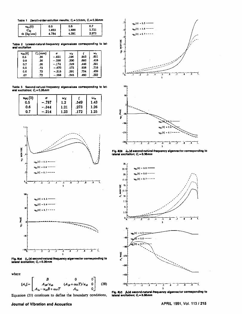
Table 1 Zeroth-order-solution results; C1: 3.Smm, C,=, 0.36mm
,,,o(O)C,,-
,_ (kUsee)
0.,5
1.6,55
4.784 0.6 I 0.7 I1.690 1.731
4.391 3.973
Table 2 Lowest-natural-lrequenoy elgenvaluos corresponding to let-oral excitation
0.6 .36
0.7 .36
0.5 .72
.72
.196 .9_53
-.288 .300 .693
-.174 .349 .446
-.670 .175 .936
-.315 .291 .734
-.188 .345 ASO
_n
.651
.416
.391
.716
.429
.392
Table 3 Second-natural-frequency elgecvalues corresponding to Jet.oral excitation; C,= 0.36ram
,,oo(O)0.50.60.7
-.7s7 .549 1.4s-.344 11.211.273 1.z6-.214 I 1.23 I .172 1.25
1.2
s" ...... x. ...-° -.. •
/ .o-° .,
8 /s °..- •
_ ,, tI
'4t ue,(Ol - 0•6
/
.2[ ull,(O ) - 0.7 ....
I
IBO
0
-90
Ue.(O) • 0.5
ue,(o) • o.6 ........
,e.(O) - 0.7 ....
.... _p-_ .
- 18,.} .2 ,3 .4 .5 .6
S
" .'7 .'a.; ,'.
Fig. 8(,,) u,l(#) second-natural.frequency elgenvector corresponding tolateral excitation; C,= O.Mmm
where
r o i][A,I= A_/u_ (A_+ a_7_/u_ (28)LA,.-u,oB+a_T A2,
Equation(21)continuestodefinetheboundaryconditions,
.7
.5
.5
,2
%'.
fue,(o) - 0.5' /
I
ue,(o) - o,s ........ //
ue.(0) .07 .... / ,/...,,,"':.
I,.,f.
.1 .2 .3 .4 .5 .6 .7 .B " .9 I.
s
18o
$o
o
"_ -90
-180
-270us,(0 ) -0.7 .... -_'",,,_
"_6°o'. .'i - .'2 " .'_ " ._ ._ ._ .7 .s .9 _.
s
Fig. 8(M _,,(_} second-nst_ral.fraquenoy elgenvector cormspondlng tolateral excitation; C, = O.36mm
2,[15 _,(o}. 0.5• ,._.(o] • 0.$ ........ °.
_.sl- _,(o). 0.7 .... , ',
_s._ ," ." ",'
10. "" /"/ I
0_. .I .2 ._, .4 .5 .6 .7 • • •s
o
-90
-180
_:270
L
-.160
"...'..-......
..... ".2............_._
•3 .4 .5 .6 .7 .8 " .'g " I',
s
Fig. 8(c) _(I) second-natural.frl<lUCney elgenvector corresponding tolateral excitation; Cr" 0.38ram
Journal of Vibration and Acoustics APRIL 1991, Vol. 113 1215

Table 4citation
• .36 - L06 •478
o.6 .36 i-.584 t .3_0.7 .36 -.4110 I .3640.5 .72 -1.12 ,505
•72 -.680 I .382
First-natural-frequency elgenvalues corresponding to axial ex-
g_1 wn• 1 1.16
.878 .706
.740 .541
.912 1.23
.829 .746
.740 .568
and an eigenvalue is obtained when the determinant of equation(27) is zero•
Numerical Results
Introduction. Figure 6 illustrates the pump-impeller andshroud geometry used by Bolleter et al. (1987) in their testprogram for radial force coefficients. Their tests were at bestefficiency point (BEP) with the pump running at 2000rpm,while developing 68m of head and 1301/sec of flow rate. Theimpeller has seven blades and an impeller exit angle of 22.5deg. The test fluid is water at 80°F. For the present study, APacross the impeller is assumed to be 70 percent of the totalhead rise of the stage. Based on pitot-tube measurements,impeller exit tangential velocity is about 50 percent of theimpeller discharge surface velocity; hence, u_o= 0.5.
Both walls of the annulus are assumed, to be smooth andrepresented by Yamada's (1962) turbulence-coefficient testdata: mr=ms= -0.25, nr=ns=0.079. The inlet loss for theannulus, _, is assumed to be 0.1. The discharge coefficient forthe seal is calculated iteratively as follows. With an assumedCde, equations (10) through (13) are used to calculate the leak-age through the impeller annulus and the pressure and tan-gential-velocity upstream of the seal. The seal is then analyzed(with the same equations) using the calculated seal inlet pres-sure and tangential velocity to determine leakage and Cd,. Theiteration continues until the leakage predictions for the exitseal and the impeller annulus agree. Table 1 below provideszeroth-order solutions.
Eigen Solution Results Corresponding to Lateral Excitation.Table 2 contains the complex eigenvalues a = o + jizd =-/'¢, + j,.,nx/i":_ for the lowest-frequency eigenvalue. Re-sults are provided for both nominal (C, = 0.36ram) and doubleradial seal clearances. Observe that the damped natural fre-quency _d ranges from about 20 percent to 30 percent of run-ning speed. Starting guesses for the eigenvalues weret_o= 0 + 0.4j, because the lowest-frequency peaks in Fig. 4(a)are around f= 0.4. Observe that the calculated ei_genvah_es areentirely consistent with the results of Fig. 4(a); specifically,the solutions are stable and highly damped, the damping factor_"decreases as u00(0) increases, and both _n and the f valuecorresponding to peaks in the foq curves decrease as us0(0)increases. The results are observed to be relatively insensitiveto changes in the exit-seal clearance.
Figure 7 contains the complex eigenvectors for theC,= 0.36mm. The tJst(s) vector has a peak amplitude at theinlet and exit with a small phase shift at the inlet. The riot(s)magnitude and phase tend to increase steadily with increasings. The.b,(s) magnitude increases steadily with increasing s untilabout s= 0.9 and then drops abruptly as it approaches the exitseal. The sharp change in u,l and Pl between s = 0.9 and s = 1.0is caused by the sharply convergent flow path, illustrated inFig. 5, as the flow approaches the exit seal. Note that the phaseof _3stis near zero until it approaches the exit and then dropsrapidly. The rapid phase shift at the exit is indicative of thelarge energy dissipation associated with the exit discharge seal.
Table 3 contains eigenvalues for the second-natural-fre-quency eigenvector. Again, the damping factor and undamped
natural frequency drop as us0(0) increases. Figure 8 illustratesthe complex eigenvectors for these eigenvalues. Comparingusj(s) in Figs. 7(a) and 8(a) shows similar mode shapes; how-ever, the peak amplitudes increase with increasing u_0(0) forthe first eigenvector but decrease with increasing uoo(0) for thesecond eigenvector. The phase of tJ0_(s) increases for the firsteigenvector with increasing s but decreases for the second ei-genvector. The/31(s) amplitudes are similar for both the firstand second eigenvectors; however, their phase behavior is quitedifferent•
Diligent searches revealed no eigenvalues with natural fre-quencies below the first eigenvalue or between the first andsecond eigenvalues.
Eigen Solution Results Corresponding to Axial Excitation.Table 4 contains the first-natural-frequency eigenvector cor-responding to axial excitation for C, = 0.36, 0.72mm. As withthe earlier results of Table 2, the damping factor and undampednatural frequency both drop as u00(O) increases. Also, the re-suits are relatively insensitive to changes in seal clearance. Theundamped natural frequencies are higher for this type of modeshape than for the corresponding lateral-excitation modeshapes.
Figure 9 illustrates the mode shapes corresponding to axial-excitation. Comparing Figs. 7 and 9 shows a pronounced dif-ference for the _,t(s) eigenvectors. For the axial case, _qj(s) isreal and, in fact, coincides with the u_o(s) solution. This resultis predicted by equation (28) since t_s_is uncoupled from tJetand ,bj and satisfies the zeroth-order continuity equation. Theuet(s) eigenvector magnitudes of Figs. 7(b) and 9(b) are similar;however, the magnitudes are much larger for the axial-exci-tation modes. The amplitude curves for ,b_(s) are similar inFigs. 7(c) and 9(c); however, the axial excitation cases are muchlarger and are relatively insensitive to changes in uoo(0).
Discussion of Approach and Results
The eigenvalues presented in Tables 2 through 4 seem to beentirely consistent with the forced-response curves of Figs. 4and 5; specifically, the natural frequencies generally lie wherethey are expected, and they and their damping factors varywith uso(0) as expected. The eigenvectors of Figs. 7, g, and 9are difficult to comment on, given that (to the writer's knowl-edge) no one has tried to either calculate or measure this typeof eigenvector in the past. The mode shapes clearly satisfy theboundary conditions and are consistent with the damped ei-genvalues to which they correspond.
The homogeneous versions of equations (14) do not (to thewriter) represent an obvious eigenvalue problem, and attemptsto formulate a recognizable eigenvalue problem by conven-tional means were not successful. Specifically, because thegoverning equations (20) are linear, one can differentiate andsubstitute to obtain a single third-order equation in:one of thevariables. Unfortunately, this approach makes the boundary-condition implementation very difficult. Moreover, the finalgoverning equation is itself not amenable to classical eigen-approaches such as central-difference finite differences; suchapproaches have proven to be notably unsuccessful for fluidmechanics problems.
The approach used here to obtain eigenvalues convergedrapidly, but the convergence characteristics suggest that theconvergence space is not convex. Specifically, full correctionsteps predicted by the secant algorithm could not be taken.Generally speaking, correction steps would be reduced by afactor of ten at the outset. The residual error in IDe[, themagnitude of 1),, would then be rapidly reduced until an ov-ershoot was observed. The problem would then be restartedat the oti corresponding to IDel min, the secant correctionfactor reduced by an additional factor of ten, and a furtherrapid incremental reduction in IDel would again be realized

w5
-3
.1 .2 .3
ue,(o) = o.s--
uoo(O) - 0.6 ........
uo,(O) = 0.7 ....
).',' .'5 .'6 /7 /8' /9'
S
9o
o
Uoo(O)= o.s_
ueo(O) = 0.6 .......
ueo(o)= 0.7....
-900', .I .2 .3 .4 .5 .6 .7 .8 .9 ' I'.
S
Fig. 9(a) _,,(I) flrsl-nalurml-hltqueney elgenvector corresponding to ax.ial excitation; C,= 0.36mm
12
10
La 8
_61
_4
2i
/ue°(o) - 0.5 /
/
.I .2 .3 .4 .5 .6 .7 .8 .9 1.
S
-9o
-180
= I ue,(o) • o.s "_'_
-270[ uol(0) = 0.6 .......
S
Fig. 9(b) @,,(s) first-natural.frequency eigenvector ¢omlspondlng to ix.Ill excibztlon; C,., 0.36mm
until an overshoot was again experienced. By following this"restart" approach, the eigenvalues could be calculated to anyaccuracy desired.
The developed algorithm would appear to be applicable toa range of fluid perturbation problems where the fluid me-chanics might have an appreciable influence on "acoustics";specifically, in circumferences where convective acceleration,Coriolis acceleration, and/or centrifugal acceleration terms arenot negligible. It would be adaptable to more strictly numericalCFD approaches such as the control-volume-based methodsof Patankar (1980).
The eigensolutions which were calculated in this work were,as specified, stimulated by forced frequency-response solu-tions. Obviously, more general solutions could be calculated;e.g., solutions of the form
us== u,_ccosnO+ u,j,sinne
ue_= uez_cosnO+ uez,sinnO
Pn =pnccosnO +pn,sinnO
with n an arbitrary integer, could be assumed for eigenvaiuesolutions. The solutions developed and presented here onlycorrespond to n = 0,1. Also, while the presented solutions cor-respond to clearance-change excitation due to impeller motion,these modes could be excited by strictly fluid oscillation.
For axial excitation, Childs' (1990) work indicates that theimpeller-shroud forces have a negligible influence on pumpvibrations. However, Williams and Childs (1989) demonstratethat "fluid resonance" phenomena can have an appreciableinfluence on lateral rotordynamics of pumps.
Acknowledgment
The results reported herein were funded in pan by NASAMarshall Space Flight Center, NASA Contract NAS 8-37821;Contract Monitor: James Cannon.
140
120
lOO
-- 60
4O
360
270
°.---...
180 _ "'" ""
uo,(o) = o.s_
uoo(O) - 0.6 .......
uOo(O) = 0.7 ....
ul "._,< -.-..
S
Fls. _ _(_ flmt-n=tur_-ff_lue_ elgenv_tor _n'Hl_l_ to _-Ill excitation; Cr=O.Mmm
Joumsl of Vibration and Acoustics APRIL 1991, Vol. 113 1 217

ReferencesBollcter, U., Wyss, A., Welte, I., and SturcMer, R., 1987, "Measurement of
Hydrodynamic Matrices of Boiler Feed Pump Impellers," ASME Jotrl_,_.OFVIIBIUtTIONS,S'I'IP,tSS, AND R1ELIAIBII.rrYIN DESIGN, Vol. 109, pp. 144-151.
Childs, D. W., and IOm, C-H, 1985, "Analysis and Testing for RotordynamicCoefficients of Turbulent Annular Seals with Different Directionally Homo-
geneous Surface Roughness Treatment for Rotor and Stator Elements," ASMEJournal of Tribology, Vol. 107, July 1985, pp. 296-306.
Chiids, D. W., 1987, "Fluid Structure Interaction Forces at Pump-Impeller-Shroud Surfaces for Rotordynamic Calculations," Rotating Machinery Dy-
namics, Vol. 2, ASME, pp. 581-593.Childs, D. W., 1989, "Fluid Structure Interaction Forces at Pump-lmpeller-
Shroud Surfaces for Rotordynamic Calculations," ASME Jo_.r_rod. or Vnnot-_oN, ACoUSTtCS, STI_SS, _ _ m Dl_olq, Vol. I!1, pp. 216-225.
Childs, D. W., 1990, "Fluid-Structure Interaction Forces at Pump-Impeller-Shroud Surfaces for Axial Vibration Analysis," ASME Jotnt_xt oF Vtatx_oN
Am3 AcousrlCS, in pre_r.Hirs, G. G., 1973, "A Bulk-Flow Theory for Turbulence in Lubricant Films,"
ASME Journal of Lubrication Technology, April 1973, pp. 137-146.Meirnvitch, L., 1985, IntrOduction to Dynamics and Control, J. Wiley.Patankar, S. V., 1980, Numerical Heat Transfer and Fluid Flow, McGraw-
Hill Co., N.Y.Williams, J., and Childs, D., "InfluenCe of Impeller Shroud Forces on Pump
Rotordynamics," presented at the 12th Biennial ASME Vibration Conference,17-20 September 1989, under review for ASME Jotn_ or VmltA_ON
Acous'rzcs.Yaraada, Y., 1962, "Resistance of Flow Through an Annulus with an Inner
Rotating Cylinder," Bull. JSME, Vol. 5, No. 18, pp. 302-310.
APPENDIX A
Perturbation Coefficients
Ais= [os(l - ms) + o,(1 - mr)lu2_o/2ho
Az,= _2ueo d_r/b2 + [o,(mr + i)_5o+ as(ms + l)#t]uso/2r as
duso
A3s =---_--+ [(2 + mr)a, + (2 + ms)as] Usa/2
- [(1 + mr)o,Bo(Ugo- r) + (1 + ms)a_lUeo]/2
2,4 te= Uso[(l - mr)(uso - r)a, + (I - ms)ueoo,]/ho
2A2a = usa(o, + as) + a,(mr + l)(ueo - r)_oUsadr
+ cr,(ms + l)Uao_l + 2r
ZA_ = o,(Ueo- r)[mr- (l + mr)(3o(Uoo- r)/Uso]+ asUeo[mS- (1 + ms)fJtUeo/U,o]
_o= (uao- r)l b2uso{1+ [(ueo- r)l buso]2}
131= uoo/b2uso[1+ (Ueo/bu,o) 2]

i..i I_
l.--J
%.J
=
I_ _
F _

m
N94- 27378
J. P. WilliamsRockwellSpace OperationsCompany,
600 Gemini, R20-B,Houston,TX 77058
D. W. ChiidsDepartmentof Mechanical Engineering,
Texas A&M University,CollegeStation, TX 77843
Influenceof ImpellerShroudForceson TurbopumpRotorDynamicsThe shrouded-impeller leakage path forces calculated by Childs (1987) have beer:
i analyzed to answer two questions. First, because of certain characteristics of th_• results of Childs, the forces could not be modeled with traditional approaches.
_ Therefore, an approach has been devised to include the forces in conventiona,
rotordynamic analyses. The forces were approximated by traditional stiffness, damp-
. ing and inertia coefficients with the addition of whirl-frequency-dependent direct
. and cross-coupled stiffness terms. The forces were found to be well-modeled with
this approach. Finally, the effect these forces had on a simple rotor-bearing system
was analyzed, and, therefore, they, in addition to seal forces, were applied to a
Jeffcott rotor. The traditional methods of dynamic system analysis were modifies
to incorporate the impeller forces and yielded results for the eigenproblem, frequency
- response, critical speed, transient response, and an iterative technique for finding
the frequency of free vibration as well as system stability. All results lead to the
conclusion that the forces have little influence on natural frequency but can have
appreciable effects on system stability. Specifically, at higher values of fluid swirl
at the leakage path entrance, relative stability is reduced. The only unexpected
_ responsecharacteristicsthatoccurredareattributedtothenonlinearityofthemodel.
Introduction
The vibration of centrifugal pumps has received increasing
attention recently because of the inability of current analysistechniques to adequately predict the dynamic characteristicsof pump designs. Failure to accurately predict vibrations has
resulted in the loss of considerable amounts of money in downtime from severe vibration problems. Massey (1985), for ex-ample, described an eleven-stage pump that became Unstable
when its running speed exceeded its critical speed by 25 percent.In other words, it whirled at 80 percent of running speed.Another example occurred in the High Pressure Oxygen Tur-bopump (HPOTP) of the Space Shuttle Main Engine (SSME)which also whirled at 80 percent of running speed (Childs andMoyer, 1985).
The hydrodynamic forces generated in many of the fluid-filled gaps within the pump are well-established contributors
to the problems cited above. This article is concerned specif-ically with the forces developed along the leakage path betweenthe impeller and the shroud, as shown in Fig. 1. As the fluidis discharged from the impeller, some will return to the lower-pressure, suction side by way of this leakage path. Leakage isminimized typically with wear ring seals, as shown. Hydro-
dynamic forces are developed along the entire leakage path,i.e., the shroud section as well as the seal. Note that these are
only parts of the total force on the impellei" and that the
impeller/volute region, balance drums, inducers, shaft, etc.
Contributedby theTechnicalCommitteeon Vibrationand Sound forpub-licationin the JomtN,,u.oF VmilATioNANDAcourncs. ManuscriptreceivedFebruary 1990.
also contribute to the dynamics of pumps, although they arenot considered here.
Unfortunately, measurements of the total force on actual
impellers have typically been obtained using pumps that have
been modified to minimize leakage path forces. However, someresults have been reported that are of importance here. Forexample, research at Cal Tech (Adkins, 1976) led to the con-clusion that the pressures in the shroud annulus contributedfrom about 50 percent to 75 percent of the total stiffness actingon the impeller. The pump used included separation rings andan enlarged shroud clearance space to minimize leakage flowforces.
Bolleter et al. (1985) used a rocking-arm mechanism to ver-tically translate the spinning impeller. Their pump had normalclearances in the leakage path; and, therefore, the forces meas-
We.It rial seals
I /' ]
baronage _ /
Rg. 1 Typical seal configurations for a multistage pump
508 I Vol. 113, OCTOBER 1991 p_N(; PA_£ ElLeN) NOT F_._, Transactions of the ASME

i
ured were more realistic. The results demonstrated that thenondimensionalized cross-coupled stiffness value was abouttwice that measured on the pump at Cal Tech (Jery et al.,1984). This suggests that the leakage path region in pumps canalso reduce the stability of impeller motion. Bolleter et al.
(1989) have recently presented extensive force-coefficient re-sults at off-design conditions.
Almost all of the analytical attempts at predicting leakagepath forces have been concerned with seals. However, Childshas extended his previous techniques in seal analysis (1980, 81,82a, 82b, 82c) to apply them to the flow within the clearancespace surrounding the shroud (1987). His work will be usedto model the seal and shroud forces in this article and will nowbe summarized.
Childs used a bulk-flow approach to obtain the governingequations of the flow of a differential element of fluid. In theseal problem, three equations were required: axial- and cir-cumferential-momentum equations as well as the continuity
equation. In the shroud problem, the axial-momentum equa-tion was replaced by a path-momentum equation, introducingadditional terms which described the centrifugal and Coriolisaccelerations of the fluid element. After a perturbation ex-pansion of the equations in the eccentricity ratio, the resultingrelationships were solved at various values of the whirl fre-quency, fl. Integration of the resulting pressure distributionacting on the shaft or shroud yielded the radial and tangentialforce as functions of whirl frequency. In addition, solutionwas carried out at various fluid circumferential velocities atthe shroud entrance. This variable is of primary importancein system stability (cross-coupled stiffness). Figure 2 shows theresults of the shroud problem for three different values of theinlet swirl velocity. The leakage path analyzed correspondedto that used by Bolleter et al. (1985) which ran at 2000 rpm.Figure 3 provides the dimensions of the pump and other dataof importance. The curves in Fig. 2 define force coefficientscorresponding to a circular orbit of amplitude and whirl fre-quency ratio f. The impeller force components are linearlyproportional to the orbit amplitude A. The sharp deviations
°Ii°°1
-- -0.6+ .4-
0 s i
.2 -I 0 I 2
Whirl r-_lumey _ (N_)
Fig. 2(_ Redlal force coefficient curves (Childs, 1987)
0.,I
I_ 0.3"
i 0.2"
EO.I'
._ 0.0'
.0A
.0.2
-2
. _ . , •
-I 0 I 2
Wlmrt Fmqu_w/_ (WD)
T,ngentlal forCe coefficient curves (ChJlds, 1987)
in the radial and tangefitial force coefficients of Fig. 2 arecaused by excitation of a ,,centrifugal-acceleration mode" nat-ural frequency. Childs (1990) has presented results for dampednatural frequencies and eigenvalues for these modes.
Nomenclature
Cx= CQ_......_s= nondimensional di-Fo rect damping coeffi-
cient
t'= cQ0_, = nondimensionalizedFo cross-coupled damp-
ing coefficient
_'/,=-_ = nondimensionalizedradial and tangentialforces on the rotor
F0 = 2R,LAP = (Childs,1987)(F)
f= f] = whirl frequency ratiocas
g=KQ0 = nondimensionalizedFo direct stiffness coef-
ficientK" = direct stiffness coef-
ficient which is afunction of the whirlfrequency ratio (F/L)
/_=k._Q0 = nondimensionalizedF0 cross-coupled stiff-
ness coefficient(Chiids, 1987)
Journal of Vibration and Acoustics
k" = cross-coupled stiff- (inlet swirl ratio)ness coefficient (Childs, 1987)which is a functionof the whirl fre- x, y = rectangular coordi-nates of rotor centerquency ratio (F/L) (L)
L = length of seal or ira- Z = complex rotor whirlpeller-shroud path amplitude (L)(L) z=x+jY = complex rotor coor-
K'I= MQ_2" = nondimensionalized dinate (L)Fo direct mass coeffi- # = phase angle of whirl
cient (Childs, 1987) from harmonic exci-
Q = rotor whirl radius tation(L) fl = rotor whirl fre-
Q0 = clearance at leakage quency (I/T)-path entrance (L) _, = natural frequency of
free vibration (1/ T)
_=Q = clearance ratio _s = shaft speed (l/T)L = shroud leakage pathR = rotor whirl ampli- coefficient subscript
tude (L) • = rotor coefficientRL.s = inlet radius of subscript
shroud leakage path s = seal coefficient sub-or seal(L) script
ilrL/s
_¢L/,=R__ s = nondimensionalized sh = shaft coefficient sub-tangential fluid ve- scriptlocity at leakage none = overall coefficientpath or seal entrance subscript
OCTOBER 1991, Vol. 113 1 509

3.55
57
175
t 0fltd_NSlON5 fN&Z MIU,.JM_[ T [RS
t
Pumpdata
shaftspeed : os : 2000 rpm
inletclearance : Qo : 3.55 mm
impeller exit angle : 22..5 o
flowrate = 130 I/see
headdeveloped : 68 m
seven-bladed impeller
working fluid is waterat 80 OF
Fig. 3 Dimensions and data for the pump tealed by Bolleler et al (Boblater at al, 1985)
In the articles cited above, Childs initially suggested the
following conventional, linear relationship to model the forces.It applies for small motion of the rotor about the centeredposition.
(1)
If circular whirl at frequency, fi, and radius, Q, is assumedsuch that
x= O cos fit, (2)y = Q sin fit,
the radial and tangential force components can be stated
_I,FF, I -(-M_+cQ+K')
After nondimensionalizing the terms as defined in Chiids(1987), Eqs. (3) become
= 37ff2-ef - l_(4)
J_l - Of+ _',#
where the definitionsof the coefficientsare included in the
Nomenclature and the other variablesare defined as follows.
p= F2RLLAP' nondimensionalized force
_-_, nondimensionalized clearance#=_0
f=fi, whirl frequency ratio
P
_, force coefficient.
The quadratic relationships of equations (4) are to be used to
obtain the dynamic coefficients of equations (I). Specifically,
a least-squares curve fit of the force curves will yield the coef-ficients. This is an adequate approach for seal forces becausethey, in general, do follow a quadratic trend. However, the
curves of Fig. 2 illustrate that shroud forces cannot be ap-proximated by equations (4); and, therefore, a traditional lin-
ear model as expressed in equations (1) will not adequatelyrepresent the forces. Although these results are unexpected,experimental measurements made by Franz and Arndt (1986)of impellers with inducers yielded very similar results.
Problem Definition
At this point, it is not known, assuming the force curves ofFig. 2 are valid, how they can best be included in traditional
rotordynamic calculations of stability, response, critical speeds,
etc. To solve this problem, the present research has been con-
ducted to answer the following questions.
(I) How can the force curves found by Childs (1987) be
incorporated in the traditional rotordynamie analysesof system response, stability, critical speeds, etc.?
(2) What effects do the forces have on a rotor-bearing
system with respect to stability, natural frequencies,imbalance response, etc.7
Before answering these questions, observe that the forces pre-
sent no new problems in a transient analysis because they couldbe applied as whirl-frequency-dependent forcing functions to
a simple rotor model such as that developed by Jeffcott (1919).Although the force components are linearly proportional to
the orbit amplitude, the equations of motion would be non-
linear because the forces depend on the whirl frequency, de-fined kinematically as
f__o_ x_-.v_ ,- w,- w,(x2 + fl) (5)
but this could be handled by integrating the equations of mo-
tion numerically with traditional methods. However, a tran-
sient analysis alone is not sufficient to obtain an understanding
of the forces, and this is why answers to the questions posedabove are necessary. The following section describes the model
used to analyze the shroud forces, and results are then given
for the eigenvalue problem and frequency response, respec-tively.
Rotordynamic Model
As shown in Fig. 4, the model is a Jeffcott rotor (Jeffcott,1919) under the application of seal and shroud forces. The
rotor itself represents a double-suction impeller, yielding twosymmetrical leakage paths. In summary, the forces on the rotor
are the shaft stiffness, two identical seal forces, and two iden-
tical shroud forces. The mathematical representation of eachforce will now be discussed.
A 90.7 kg (2001b) rotor is assumed. In addition, the shaft
stiffness used (Ash-- .2987 MN/m) makes the natural frequency
of forward whirl (to be defined later) equal to 80 percent of
shaft speed. This choice is not completely arbitrary since this
frequency corresponds to that observed in the examples citedin the Introduction (Massey, 1985; Childs and Moyer, 1985).
The seals modeled are smooth, wear ring seals with a clear-
ance and diameter of .36 mm and 236 ram, respectively. Theleast-squares approach of Childs described earlier has been
carried out, and the resulting dynamic coefficients are given
510 I Vol. 113, OCTOBER 1991 Transactions of the ASME

flexible shaft
rigid support
seal forces
L/ Lrigid support
shroud fon:es
Fig. 4 Jelfcott-based, double-suction impeller leakage path model
Table 1
"StL MI C, e,
kg Ns/m Ns/m
.5 .3111 3356.0 78.6
.6 .3398 2167.0 89.6
.7 I .3714 970.9 101.3
Coefficients for one wear ring seal
Ks k,
MN/m MN/m
.6121 .4628
.5443 .4611
.4755 .4455
in Table I. The analysis used has at times under-predicted thetrue value of the direct stiffness. Therefore, Ks is doubled whenthe coefficients of the entire model are assembled. This mod-ification of Ks has no influence on the results, since the shaftstiffness is selected to yield a desired system natural frequency.
As described in the introduction, conventional stiffness,damping and mass coefficients cannot completely describe theimpeller-shroud forces calculated by Childs and shown in Fig.2. Therefore, the following method has been devised. First, acurve fit of the force curves is carried out, yielding dynamiccoefficients which describe the quadratic variation of the forceswith respect to the whirl frequency ratio as described above.The difference between these curve fits and the actual force
curves is modeled by direct and cross-coupled stiffness coef-ficients which are functions of whirl frequency ratio. The math-ematical equivalent of this approach will now be discussed.
The following modified forms of equations (4) express themethod with which the impeller-shroud forces are modeled.
= _da- eL/- [RL+ R" ¢J')]
= - CL/+ [& + P tf)], (6)4
where/_" and _" representthe nondimensionalized deviationsbetween the force curves and the approximating quadraticexpressions.Figure 5 illustrates/_" and E°, respectively. Notethat, although they represent forces proportional to displace-ment, they are not traditional stiffness coefficients since theyare functions of whirl frequency ratio. Separating the forcecoefficients into whirl-frequency-independent and whirl-fre-quency-dependent terms doesnot introduce any approximationto the force definitions. Equations (1) are now rewritten as
[ K,+K'u') k +J,'Cr)]+ -kL-k'(f) KL+A"tf)J(y)" (7)
In a mathematical sense, the tangential force accounted forby k* could be modeled as a damping coefficient; however,the result of Fig. 5(b) confirms the wisdom of modeling thedeviation of the tangential-force coefficient by a whirl-fre-quency-dependent cross-coupled-stiffness-coefficient. Specif-ically, k ° oscillates about zero and approaches zero as the inletswirl ratio is reduced. Finally, observe that equations (7) are,
0.!
0.0
--9.!
-2
Fig.S(J)
-I 0 1 2
Whirl FrequencyRatio (NO)
Dapendenoy of K" on whld frequency ratio
°3 / 'nk,S_" [1"° I: I
1-'-.'1
1
o.ot -0.1
-02 , - ,
-2 -I 0
_g. s(b)
I 2Whirl Fmqumc? RJuo (NO)
Dependency of K" on whld frequency ratio
Table 2 Approximating coefficients for one leakage path
M/, U/, cL Kz, kLkg Ns/m Ns[m IMN/m MN/m
3.469 2037 969.9 .06781 .3137
in general, nonlinear differential equations. To understand thisstatement, recall that the general definition of the whirl fre-quency ratio, f, is given in equation (5). If the rotor precessionhas a constant radius and rate, f is a constant and the motionis linear. However, for general motion, f is variable and afunction of the motion.
After performing the asymptotic least-squares curve fit toFig. 2, the resulting coefficients of equation (6) are given inTable 2.
in summary, the following equations represent how the over-all coefficients for the model are defined.
M= M, + 2(Ms + ML)c=2(Cs+CD +-_
c=2(c,+cL) (8)
K = K_ + 2(ZK, + KD + 2K" =K+2K"k= 2(ks + kL) + 2k" =k+ 2k'.
Particular coefficients are doubled because there are twoseals and two leakage paths in a double suction pump. Thequantity, C, must be added to the model to yield reasonablestability. If the eijenvalues of the overall system are obtainedwithout adding C, the system is found to be unstable. There-fore, by adding another damping term (C= 10,422 Ns/m),reasonable stability, which is consistent with operating pumpexperience, is ensured. The following equation represents thecomplete model used to model the forces on the rotor.
Journal of Vibration and Acoustics OCTOBER 1991, Vol. 113 1 511

.5
.6
.7
Table 3 Coeiflclents _r overall model
M C c
kg Ns/mi Ns/rn
98.240 21208 2097.1
98.298 18830 2119.1
98.361 16438 2142.4
K k
MN/m MN/m
2.8827 1.5549
2.6115 1.5494
2.3363 1.5184
Table 4and without K" and k"
_,L -- with_j
K ° and k"
.5 .747
.6 .777
.7 .800
Natural frequencies of free vlbretlon for the pump modal with
w...._nwithout6.t I
K" and k °
.727
.724
Percent
Decrease
2168%6.82%
.715 10.63%
°1 I
i
-80 0
-2 -I 0
Fig. 6
! 2
Whirl F_qu_ncy Ra_c (ND)
Real pat/of the algenvalues for the forward-whlrl mode
l.l
I.I.0"
!0,:
OJi'
"! 0.7 '
0.6 , 0 °
-2 -I 0 I 2
wh_ _ Rape(WD)
Fig. 7 Imaginary part of the elgenvaluas for the forward.whirl mode
[,<<,> {::,7+ -k(f) K(/)J (yJ = . (0)
Table 3 contains the numerical values for this analysis. Thesecoefficients combine to make the damping for the uncoupledsystem, defined by C/2x/-K-M, equal to 63 percent, 59 percent,and 54 percent of critical damping for the three swirl ratiosshown, respectively. Again,/_" and _r, are illustrated in Fig.5 and are defined analytically with cubic-spline curve fits.
Natural Frequency Determination
The characteristic equation for Eq. (9) is
[M_2+C_+K(f)12+[c_+k(f)lz=O, (10a)
where _= s/,_,.For each whirl-frequencyratiof,two pairsofcomplex conjugaterootsofthe form
_=a_./"A_; i= 1,2 (lOb)
can be calculatedcorrespondingto forward and backwardwhirlingmodes. The concernhere isfindingthe naturalfre-
Table S Real parts of the eigenvalues for the model with and withoutK" and k"
.5
.6
.7
Real part with Real part without Percent
K" and k" K" and k* Decrease
1/sec 1�see-55.9 -60.3 7.87%
-31.1 -47.2 51.80%
-13.8 -34.5 150.00%
quency for forward whirling motion. Figure 7 illustrates theeigenvalue solutions to Eq. (10a) versus f.
Free whirl of the rotor occurs only when the imaginary panof an eigenvalue equals the whirl frequency ratio f in Fig. 7;i.e., Xz=f. The three points at which the Xz=f line intersectsthe k(.f) curves defines the forward-whirl natural frequenciesfor the three inlet swirl ratios. The real part of the eigenvalueat this natural frequency defines the rotor's damping.
To find the "natural frequency" and damping of free whirl,the following iterative technique has been used. First, a whirlfrequency ratio is assumed. From this value, the correspondingvalues of K and k are obtained from the data shown in Fig.5 from which the eigenvalues are found using Eq. (10). Thesefirst two steps are equivalent to finding a point on the curvesof Figs. 6 and 7. The imaginary part of the forward-whirleigenvalue is compared to the whirl frequency used. If theyare the same, the natural frequency at which free vibrationtakes place is defined. If they are different, the imaginary partof the forward-whirl root becomes the assumed whirl frequencyratio, and the same steps are carried out until convergenceoccurs. Note that this calculation procedure yields the dampednatural frequency for the system.
Tables 4 and 5 show results of the above algorithm. Alsoincluded are the eigenvalues of the same model neglecting K"and k', which correspond to a pure quadratic approximationof the leakage path forces as in equations (4). The eigenvaluesillustrate at least two important conclusions about the effectsof the values of K" and k'. First, the natural frequency in-creases when K" and k" are included as well as when the swirlratio is increased. The variation of K" in Fig. 5 explains theseobservations. More importantly, the percent differences be-tween the two models show that the values of K' and k' havevery little effect on natural frequency. Second, stability is re-duced when K" and k" areincludedand when theswirlratioisincreased.The variationofk" inFig.5isthecauseof these
observations.Finally,thepercentdifferencesbetweenthetwomodelsshowsthatK* and k' cancauseappreciablereductionsinrelativestability.To show thatthe stabilityand frequencyof freevibration
are determinedonly by theroot obtainedfrom the iterative
approach describedearlier,theequationsof motion (9)wereintegratedina seriesof transient,free-vibrationsimulations.Initialconditionswerean initialdisplacementof.127mm (.005
in)and velocityequaltoRLws (synchronouswhirl).Figure8includesthe resultingorbitand a time historyof the whirl
frequencyratioforfreevibrationand an inletswirlratioof0.7.As shown, therotorexecuteda well-dampedspiralorbit.
512 I Vol. 113, OCTOBER 1991 Transactions of the ASME

O004
0¸002¸
!.0000'
1.s .0002'
-0.004
.0g04
Fig._a)
-0.002 --0C_0 0.002 0004
x .C_ _oud lad_ Cieatw_ (?_D)
Rotor orbit dudng free vibration
Fig.8(b)
1.1
,0j
_a0fl
0"7 10_
0,0 0_ I.O ! .5
The (lee1
Time history of rotor whirl frequency ratio during free vibration
um!.zble eiEen vldut.s
eig,_vadua0
• 2 -I 0 I 2
WI_] Fmq.ency R_o a_O)
Fig. 9 Real part of the aiganvaluas for the forward.whirl mode with a
12.5 percent reduction in direct damping
The whirl frequency ratio of the orbit was exactly 0.8, whichcorresponds to the natural frequency found earlier. The othertwo swirl ratios yield similar results.
To verify that the stability of the model is described onlyby the real part of the eigenvalues obtained with the iterativeapproach described above, the direct damping coefficient wasreduced by 12.5 percent producing a range of unstable eigen-values as shown in Fig. 9 where the real part of the forward-whirl root is positive between whirl frequency ratios of 0.41and 0.57. The natural frequency of this altered model corre-sponds to a stable eigenvalue and is .82514,. Integration of theequations of motion were altered to include a harmonic forcing
0.02'
0.01
J
_ 0.1_
_ ..0.01
4).02
x-C, oonJu,am.51uo._l b_ Ck=nmoc (HD)
Fig. 10(a) Rotor orbit during harmonic excitation at 50 percent of shaft
speed and 12.5 percent reduction in dlrecl damping
|.0"
i 0.0
•1.0
0.0 0.5 I.O 1.5"r'mz,e (El:)
Fig. iO(b) Time history of rotor whirl frequency ratio dudng harmonicexcitation at 50 percent of shaft speed and a 12.5 percent reduction in
direct damping
!0 3t
0
. . m i i •
I 2 1 4Fml_.mcy_ h_Lr_Speed (T_rD_
Fig. 10(@ FFT of the response of the rotor during harmonic excitation
at 50 percent of shall speed and • 12.5 percent reduction in direct
damping_
also tried. Using a stable value of 0.7ws, for example, theresponse did not behave in the same manner; instead, the orbitreached a steady state circuliii" p-afli _i__hi_-/tx¢iiaii-6h-_requeneyas would be expected from a linear system. However, forcingat .375w,, thecqaaracte_ of the results from forcing at .5,,occurred again, as can be seenin Fig. I 1, which again contain
function with an amplitude of 5N which forced the rotor in a _,time his_or);of the whirl frequency ratio and an FFTcircular direction at a frequency of .Sw,. Figure 10 includesthe resulting orbit, whirl frequency ratio time history, and aFast Fourier Transform (FFT) of the x-coordinate, respec-tively. Even though the forcing frequency was within the un-stable range of frequencies, the figures show that the systemwas stable in that its orbit did not grow without bound. Theloops and limit cycle behavior are the results of the nonlin-earities in the model. TheFFT shows that the steady state orbitconsisted of response at both the forcing frequency, .Sw,, andthe natural frequency, .825%. Other forcing frequencies were
of the response. Only forcing frequencies below and withinthe unstable zone resulted in this behavior. Only when thedirect damping coefficient was reduced until the natural fre-quency corresponded to an unstable eigenvalue did the re-sponsebecome unstable in a linear sense,where the orbit grewwithout bound at the natural frequency. The fundamentalresult from this analysis is a verification that a range of whirlfrequencies yielding eigenvalues with positive real pans doesnot cause the system response to grow without bound unlessit includes the system natural frequency. In addition, the non-
Journal of Vibration and Acoustics OCTOBER 1991, Vol. 113 1 513

Fig,11(_speed •nd I 12.5 percent reduction in direct damping
o mo 61 -- .,thK*.k" I
o.00_ g $
_4
o._) 3
- 0000 000_ 0 0
x-Clim/lll_li.oud lltlll _ (ND) -1 0 I 2
Rotor orbit during harmonic excitation St 37.5 percent of shaft whirl Fre4ue_y RJu_o(ND)Fig. 12 Frequency response: whirl amplitude
2'
I •
4
-5
OJO 0.$ 1.0 1.5(*nO
Fig. 11(b1 Time hi•tory of rotor whirl frequency ratio during harmonic
excltallon at 37.5 percent of shill speed and I 12.S percent reductionIn direct damping
0.005
0,003
N
!:![0 '2 3 ,
Fig. 11(6") FFT of the re•pon•e of the rotor during harmonic excitation
It 37.5 percent of •haft •peed and • 12.5 percent reduction in directdamping
linearitiesofthesystemcan causea limitcycletooccurundercertainconditions.
Finally,thecriticalspeedoftherotorcannotbe calculatedunlessforcecurvesareavailableatothershaftspeeds.Inthiscase,the naturalfrequencyiscalculatedwith the iterativemethod justdescribed,but at a number of shaftspeeds.Aplotofnaturalfrequencyasa functionof shaftspeedisthendrawn, analogous to "critical speed maps" in fluid-film bear-ing analysis. The critical speed is defined as the speed wherethe natural frequency is equal to the shaft speed.
Frequency Response
As discussed earlier, the following are the equations of mo-tion of the model
+
-k(f) K(f) = r_sinflt3'(11)
200'
100"
,o
L* 0<
-100
-200'
-2
Fig. 13
-I 0 I 2
whid r-_ it_ (ND)
Frequency response: phase ingle
where the right-hand side represents a harmonic forcing func-tion appropriate to frequency response analyses. As in tradi-tional methods, the transient solution is assumed to decay withtime, and only the steady-state response of the rotor is con-sidered. Obviously, frequency response solutions are only validwhen the system is stable, precluding the type of responseillustrated in Figs. 10 and I I. The forcing frequency is definedby fl which has been used to represent whirl speed. Since thesteady-state motion is assumed to occur at the same frequencyas the excitation, this should not cause confusion. Note thatthe model is now linear because the whirl frequency ratio and,hence, the stiffnesses are constant. Multiplying the secondequation by the complex number i, the equations can be com-bined into one in terms of the complex variable z.
Mi + (C- ic) k + (K- ik)z=Fe 'u'. (12)
Assuming steady-state motion of the following form
z= Re_*, (13)
whereR denotesthewhirlamplitude,and ¢ isthephaseangleyields
R K
F/K 4[K_MI_ +cflI2 +[C_I_k]_ (14)_,r k-cn l
Equations (14) were solved using the present model data,and the results for a swirl ratio of 0.7 are shown in Figs. 12and 13. Also included are the same results for the model withK* and k* neglected. Again, in obtaining frequency curves asshown in Figs. 12 and 13, the stiffness terms must be calculatedat the corresponding whirl frequency ratio.
The swirl ratio of 0.7, used in Figs. 12 and 13, exhibited thelargest variation in amplitude and phase at the whirl frequencyratio of .80, the system natural frequency. An amplitude dif-

ference of about 60 percent is shown between the curves, sug-
gesting that K* and k ° have significant influence on the system
primarily at this frequency. The swirl ratios of 0.6 and 0.5exhibited similar but decreasing results in both the amplitude
and phase curves, having differences in amplitude at the peak
value of 35 percent and 6 percent, respectively. In fact, the
curves were almost identical in the case corresponding to a
swirl ratio of 0.5. Note that these resonance peaks occurred
in all cases at the corresponding natural frequencies found in
the previous section, further verifying the preceding results.The difference in the response to synchronous imbalance ex-
citation (f= l) between the two models is small, and this sug-
gests that the leakage path forces have negligible effects onimbalance response. However, the presence of a subsynchron-
ous excitation near the natural frequency can result in large
increases in response amplitude when k ° is included.
Summary and Conclusions
The impeller-shroud forces have been separated into (a) con-stant (whirl frequency-independent) stiffness, damping andmass coefficients and (b) direct and cross-coupled added stiff-
ness coefficients which ate functions of whirl frequency. Withthis approach, the model can be analyzed using traditionaltechniques with a few modifications. A new iterative technique
was used in the determination of the rotor's natural frequency
and damping. The whirl-frequency-dependent stiffness termswere seen to be convenient and effective models for the im-
peller-shroud force nonlinearities.When the values of the added stiffness coefficients, K" and
t', were included in addition to the frequency-independentcoefficients, a number of effects resulted. First, the natural
frequency was seen to increase by a small amount, suggestingthat K" could be neglected when only the natural frequency
is important. In addition, the stability is seen to decrease whenR* is included. This effect is appreciable, so stability calcu-lations should include k*. The frequency response analysis
showed synchronous response to imbalance is increased by thestiffnesses although by only a small amount. Appreciable dif-
ferences in response due to subsynchronous excitation occuronly at or near the natural frequency and become negligibleat low values of the inlet swirl ratio.
The nonlinearity introduced by the whirl-frequency-de-
pendency of the force coefficients resulted in limit cycles and
nonsynchronous response in some cases.
ReferencesAdtkins, D., 1976, "Analyses of Hydrodynamic Forces on Centrifugal Pump
Impellers," M.S. Thesis, California Institute of Technology, Pasadena.Bollc_cr, U., Wyss, A., Welte, I., and Sturchler, R., 1985, "Measurements
of Hydrodynamic Interaction Matricesof Boiler Feed Pump Impellers," ASME,Paper No. 85-DET-148.
Bollcter, 12., Leibundgut, E., Sturchler, R., and McCloskey, T., 1989, "Hy-draulic Interaction and Exc_tasionForces of High Head Pump Impellers," pre-sented at the ASCE/ASME Pumping Machinery Symposium, July 9-12, 1989.
Childs, D., Dressman, J., and Childs, S., 1980, "Testing of Turbulent Sealsfor Rotordynamic Coefficienu," Proc. of Workshop on Rotordynamic Insta-bility Problems m High Performance Turbomachinery, Texas A&M University,NASA CP-2133, pp. 121-38.
Child.s, D., 1981, "Convergent-Tapered Annular Seals: Analysis for Rotor-dynamic Coefficients," Symposium Vol., Fluid/Structure Interactions Turbo-much., ASMW Winter Annual Meeting, pp. 35--44.
Childs, D., 1952a, "Dynamic Analysis of Turbulent Annular Studs Based onHits' Lubrication Equations," ASME Paper No. 82-Lub-41.
C'hilds,D., 1982b, "Pinite-Len_h Solutions for Rotordynamic Coefficientsof Turbulent Annular Scab," ASME Paper No. $2.Lub-42.
Childs, D., and Dressman, J., 1982c, "Testing of Turbulent Seals for Ro-tordynamic Coefficients," Proceedings of Workshop on Rotordynamic Insta-bility Problems in High Performance Turbomachinery, Texas A&M University,NASA CP-2250, pp. 157-71.
Childs, D., and Moyer, D., 1985, "Vibration Characteristics of the HPO'rP(High PressureOxygen Tutbopump) of the SSME (Space Shuttle Main Engine),"ASME Journal of Engineeringfor Gas Turbines and Power, Vol. 107, pp, 152-159.
Childs, D., 1987, "Fluid-Structure Interaction Forces At Pump-Impeller-Shroud Surfaces for Rotordymunic Calculations," Texas A&M University, Me-chanical Engineering Dept., ASME Vibration Conference, Boston, Mass.
Childs, D., 1990, "Centrifugal-Acceleration Modes for Incompressible Fluidin the Leakage Analysis Between a Shrouded Pump Impeller and Its Housing,"ASME JOUgNAtor' VnUU,_ONANDACOUSTICS,May 1990.
Franz, R., and Arndt, N., 1956, "Measurement of Hydrodynamic Forces onthe Impeller of the SSME," Report No. E2A9.2, California Institute of Tech-nology, Pasadena.
Jeffcott, H., 1919, "The Lateral Vibration of Loaded Shafts in the Neigh-borhood of a Whirling Spoed--The Effect of Want of Balance," The Philo-sophical Magazine, Voi. 6, No. 3"/, pp. 304-314.
Jery, IL, Acosta, J., Brennen, C., and Caughey, T., 1984, "HydrodynamicImpeller Stiffness, Damping and Inertia In the Rotordynamics of CentrifugalFlow Pumps." Proceedings of Workshop on Rotordynamic Instability Problemsin High Performance Turbomaphinery. TexasA&M University, NASA CP-233g,pp. 13%160.
Massey, 1. C., 1985. "Subsynchronous Vibration Problems in High SpeedMultistage Centrifugal pumps," Proceedings of the 14th Turbomach inery Sym-posium, TurbomachinerYLaboratories, Texas A&M University. pp. 11-16.
.Io,rnal of Vibration and Acoustics OCTOBER 1991, Vol. 113 I 515

_0 l..J-_ I--._

Reprinted from March 1992, Vol. i 14, Journal of Fluids Engineering
D. W. ChildsTurbomachinery Laboratories,
MechanicalEngineering Deparlment,Texas A&M University,
College Station, Texas 77843
PressureOscillationin theLeakage Annulus BetweenaShrouded Impeller and Its
Housing Due to Impel!er-D,scharge-PressureDzsturbances
An analysis is presented for the perturbed flow in the leakage path between a
shrouded-pump impeller and its housing caused by oscillations in the impeller-
discharge pressure. A bulk-flow model is used for the analysis consisting of the path-
momentum, circumferential-momentum, and continuing equations. Shear stress at
the impeller and housing surfaces are modeled according to Hirs" turbulent lubri-
cation model. In the present analysis, perturbations of the impeller discharge pressure
are used to excite the fluid annulus. The circumferential variation of the discharge
pressure is expanded in a Fourier series up to order n,, where nl is the number ofimpeller blades. A precession of the impeller wave pattern in the same direction or
opposite to pump rotation is then assumed to completely define the disturbanceexcitation. Predictions show that the first (lowest-frequency) "centrifugal-accel-
eration '" mode of the fluid within the annulus has its peak pressure amplitude near
the wearing-ring seal. Pressure oscillations from the impeller can either be attenuated
or (sharply) magnified depending on: Ca) the tangential velocity ratio of the fluidentering the seal, (b) the order of the fourier coefficient, and (c) the closeness of
the precessional frequency of the rotating pressure field to the first natural frequency
of the fluid annulus, and (d) the clearance in the wearing-ring seal.
Introduction
The present w-6rk is-stimulated:by experiences with the SSME
HPFTP (Space Shuttle Main Engine, High Pressure FuelTur-...._b-op'u'mp) _;(_ar]ng:rifig S-da_fs. _ s-tepped, 3-cavity, tooth-on-
rotor, ]abyrin_-seal design is used. The stator for the seal is: made _rom_t_L-F_ =/_Iastic that is somewhat similar to nylon.
In some cases, post-test inspection" of the stator element has
reveaied that ]nt_r_t:-pdi//is-in ffi_e stator :r_aterial have meltedand then resolidified, despite being in contact with liquid hy-
drogen. One hypothesis for this exceptional outcome was thatthe material had been subjected to cyclical stresses which gen-erated heat due to hysteresis. Because of poor conduction
properties of the material, the heat could not be dissipated,the temperature rose, and melting resulted. "What pressureoscillations are driving the cyclical stresses?", is an obvious
question in reviewing this scenario. The present analysis ex-amines "centrifugal-acceleration" modes, arising between the
impeller shroud and its housing and driven by pressure oscil-lations from the pump, as an answer to this question.
_The work reported herein was supported by NASA Marshall Space FlightCenter under contract NAS 8-37821; contract technical monitor:James Cannon.
Contributed by the Fluids Engineering Division for publication in the JouRlq_o.or FLtnVSE]qGZ_EEVaNG.Manuscript received by the Fluids EngineeringDivisionAugust 20. 1990.
Journal of Fluids Engineering_N_ PAG;EBLANK NOT Flti_D
Figure 1 illustrates an impeller stage of a multi-stage cen-trifugal pump. Leakage along the front side of the impeller,from impeller discharge to inlet, is restricted by a wearing-ring
seal, while leakage along the back side is restricted by either
an interstage seal or a balance-piston discharge seal. The pres-ent analysis considers perturbed flow in the leakage paths be-
tween the impeller-shroud surface and its housing.
Prior analyses by the author of those annulli have beenconcerned with lateral (1987, 1989) and axial (1990a) reaction
forces developed by the impeller shrouds as a consequence ofharmonic clearance changes due to impeller motion. These
analyses have been based on "bulk-flow" models which neglectthe variation in the dependent variables across the fluid film.The model consists of the path and circumferential momentum
equations and the continuity equations.The analyses cited have yielded force and moment coeffi-
cients due to impeller motion but have also predicted "reso-
nance" phenomena, which are caused by the centrifugal-acceleration body forces present in the path momentum equa-tions. An algorithm was developed (1990b) to calculate the
complex eigenvalues and eigenvectors associated with theseresonances. In the present analysis, the harmonic response ofthe flow within the annulus is examined due to time and cir-
cumferential variations in the discharge pressure of the im-
peller.
MARCH 1992, Vol. 114 I 61

WEAR RII_SEAL
B
IMPELLER SHROUD
_
Fig. 1 Impeller leakage paths
XFig. 2 Impeller surface geomelry
the initial point Ri' Zi to an arbitrary point R, Z is denoted
by S and defined by
S= 1 + du = i + du (1)Zi R i
Geometry and _K_i_'.n_e_mati__ .... ==_ _= _ :_ :_;; __:= - _:_ _ _ _.. ....... I_ _e= e/:(uaffons _cla foild_v_ _the path coordinate S and
Figure l illustrates the annular leakage paths along the front .... _, ....... _ =_ .............................. • .... •.... ,__ _r _ _..,. ..... angutar cooramate t_are used as independent spatial variabIes
ano oacg SlOeS oI a [ypical snrouoeu lmp¢|l¢l ul _, niu.iata_ The _:L_,_ _:= _ . . . , _==_ .... =.e cooralnates z, K ae_mtng the Impeller surface are excentrifugal pump. The present discussion concentrates on the .... .......... _ :: ii : -
flow and pressure fields within the forward annulus; however, press,ca a s parametric tunctmns of S, i.e., Z(S), R (S). The- , • .................... 2 __ :, iengm o! tlae leakage path along the impeller face is defined
the analysis can also oe applleO tO me re,a[ ammm_, t_ .- . ..........lustrated in Fig. 2, the outer surface of the impeller is a surface ... oy .
of revolution formed by rotating the curve R= R(Z)about f z_+t [ ['dR_2
the Z axis. A point on the surface may be located by the L, = ,!.z|_ ''[_t I + _--i\dZ] du (2)coordinates Z, R (Z), 0. The length along the curve R (Z) from
2Ahhough the leakage flow is normally up the backside of all impellers except
the last impeller, the governing equations would continue to be valid irrespective
of the now direction.
Governing Equations
Returning to Fig. 2, the path coordinate S and circumfer-ential coordinate RO are used to locate a fluid differential
Nomenclature
A2s, A3s, A_, A3o =
b = V/Rw =
c.=
C/ _-
C,=f = fl/co =
f° =
f+l - nl _(nt - n2)
h= H/C_ =H=
G=
n =
p=P/pV_ =p,(O,t) =
p,(O,t) =
coefficients introduced in Eq. (12)nondimensional velocity ratio
discharge coefficient for the exit wear-
ring seal introduced in Eq. (7)initial (s = 0) clearance (L)
exit seal clearance (L)
nondimensional precession frequency
nondimensionalized precession fie-
quency yielding a maximum response
pressure
positive, dominant, nondimensional,precession frequency predicted for an
impeller with nl blades in a diffuser
with nz bladesnondimensionalized clearance
clearance between impeiier shroud and
housing (L)
leakage-path length, defined by Eq.(2), (L)
order of Fourier coefficient, intro-
duced in Eq. (13).
nondimensional static fluid pressure
prescribed annulus supply pressure
(impeller exit pressure)
prescribed annulus exit pressure
(impeller inlet pressure)
62 I Vol, 114, MARCH 1992.... : : S"J .....
P = fluid static pressure (F/L 2)R = radial coordinate (L)R_ = initial (s = O) radius (L)
r= R/R_ = nondimensionalized radial coordinate
R_=2HU,/_ = path-velocity Reyno!dsnumber
S = path coordinate introduced in Eq. (1),(L)
s=S/Ls = nondimensionalized path lengthT=Ls/V_ = representative transit time for fluid
traversing the leakage path (7)
u, = U,/V_ = nondimensionalized path fluid velocityus = Uo/R,w = nondimensionalized circumferential
fluid velocityV_ = initial (s= 0) path fluid velocity
= perturbation coefficient
= pump running speed (7-_)
fl _ excitation frequenc 7 (7- _)p = fluid density (M/L _)0 = circumferential coordinate
o,, o, -= normalized friction factors, defined byEq. (! 1)
r--rt = nondimensionalized time
= entrance-loss coefficient introduced in
Eq. (7)
= kinematic viscosity (LZT - _)
Overbars denote complex variables; see Eq. (16). Subscripts 0and 1 denote zeroth- and first-order solutions, respectively,
Transactions of the ASME

element of thickness H(S, 0, t). From Childs (1987), the con-
tinuity equation can be stated
-_-+_ (U,H) +_ (Ud-t) + _ V,=0 (3a)
where U_ and Ue are the path and circumferential bulk-velocitycomponents, respectively. The path and circumferential mo-
mentum equations are stated
OP-H ='= = "rs_+ rsr-pH --
03
H OP---- -- = res + VOr
R 00
U_ dR
R dS
. [au_ at:, uo au, u,) (3b)
/Due Due ue Duo UoU_OR_+oy[-_ +-_--E+-_- _ u,+ -fi _] (3c)
Following Hirs' approach (1973), the wall shear-stress defi-nitions in these equations can be stated
ffl$+l2 ms
r_=--_ pU,R, [I +(Ue/U,)2]" 2
mr4. Inr
r,, =_ pV2,R?'l l + [(U,- R_)/U,]2}--i -
/'IS ms+l
r0,=_ pUoU, R'7[I + (Uo/U,)2] 2
mrs- II'l r mr
re,=-_ pU,(Uo-R_o)R, { I +[(Uo-Rw)/U,]2I'--7 - (4)
where
Rs = 2HU,/p (5)
Nondimensionalization and Perturbation Analysis
The governing equations definethe bulk-flow velocitycom-
ponents (U_, U0) and the pressure P as a function of the co-
ordinates (R0, S) and time, t. They are conveniently
nondimensionalized by introducing the following variables
u, = U,/E, us = U,/R_, p = Plpv_
s=S/Ls, r= RIRi, b= Vi/R,w
r=o_t, T= Ls/V, (6)
The present analysis examines the changes in (u,, u0, p) due
to changes in the impeiler's discharge or inlet pressure. Fol-
lowing conventional notation, pressure drops at the annulusinlet and exit are stated
P, (O,t) - P(O,a,t) = p(l + OU_(O,a,t)/2
P(L,, O, t)-Pc(O,t)=pCacU_(Ls,O,t)/2 (7)
Note specifically that the (upstream) supply and (downstream)
exit pressure are now functions of time. Assume that the os-
cillations consist of a small perturbation of the form
P,(O,t) = Pso + ePsl (O,t),P,(e,t) = Peo + _Pet (e,t)
and introduce nondimensional variables to yield the followingzeroth
po(O) =P,o- ( 1 - 0/2
p(l) =p= + Cd,z_( 1)/2 (8)
and first-order equations
P,i (e,t) -Pl (O,e,t) = ( l + _)u,i (O,O,t)
Pl (1,0,t) -Pc, (O,t) = Cd_uso(l)usl (l,O,t) (9)
555
57
175
Fig. 3 Example Impeller, Bolleter el al. (1987)
The perturbed supply and exit pressures P,i (O,t), pel(O,t) cannow be specified functions of time and provide excitation forthe perturbed flowfield within the annulus.
Expansion of the dependent variables of Eq. (3) in pertur-bation equations yields:
Zeroth-Order Equations
(a) Path-Momentum Equation
dpo 1 (js) _o [ ____) l dho-E+ hod,(b)
(c)
l dr] 2;'_ssJUso=O (10a)
Circumferential-Momentum Equation
duoo Uoo dr
"--_-s + 7 _+ [a,(ueo-r) +asUoo]/2=O (10b)
Continuity Equation
rhou_o = 1 (10c)
The quantities as and a, are defined by
a,=(Ls/Ho)ks, a,=(Ls/Ho)k, (11)
where X, and X, are the dimensionless stator and rotor frictionfactors:
mt¢+l
hs = nsR_[l + (uoo/buso)2]"-7
mr+ I
X, = nrR_" l I + [(uoo- r) /bu,o] 2 I
The continuity equation has been used to eliminate duso/dsfrom Eq. (lOa). The momentum equations define the pressure
and velocity distributions for a centered impeller position. They
are coupled and nonlinear and must be solved iteratively. Theinitial condition for ueo(O) is obtained from the exit flow con-
dition of the impeller. Zeroth-order pressure boundary con-ditions are provided by Eq. (8).
Figure 3 illustrates the pump-impeller and shroud geometry
used by Bolleter et al. (1987) in theirtest program for radial
force coefficients. Their tests were at best efficiency point(BEP) with the pump running at 2000 rpm, while developing68m of head and 1301/s of flow rate. The impeller has sevenblades and an impeller exit angle of 22.5 ° . The test fluid is
water at 26.6°C. For the present study, AP across the impeller
is assumed to be 70 percent of the total head rise of the stage.
Based on pitot-tube measurements, impeller-exit-tangential ve-
locity is about 50 percent of the impeller discharge surfacevelocity; hence, Ueo -= 0.5.
Journal of Fluids Engineering MARCH 1992, Vol. 114 1 63

Table 1 Zeroth-order-solution results; Ci = 3.5ram, C, =
0.36ram
ueo(O) 0.5 0.6 0.7R_ 9377 8907 8426Cat 2.068 2.098 2.130
rh (kg/sec) 4.448 4.225 3.997
Table 1 provides the zeroth-order solutions for new (original-
clearance) exit wearing-ring seals. The R_0 values on the order
of 10,000 are low in comparison to the circumferential Reyn-
olds number R_ = 2HUeo/v which varies along the path, but
is on the order of 250,000. These leakage results were obtained
iteratively starting with guessed values for the seal inlet values
of pressure and tangential velocities and yielding an initial
estimate for Cde. With this estimate for Cd,, the leakage iscalculated through the annulus which yields new inlet condi-
tions for the seal. Solutions are "bounced" back and forth
between the seal and the annulus until the same leakage value
is obtained for both flow paths (four-pIace accuracy).
First-Order Equations
(a) Path-Momentum Equation
Opl + uotA2s + uslA3sOs
r 00 -_sJ =°(12a)
(b) Circumferential-Momentum Equation
L_ 10p,+b-if,,7- _ uo,A2e+ us,A3o
ooT aU°l+ooTUe° ou +Uso =0 (12b)+Or r a as j
(c) Continuity Equation
au_, ooT auo, {I dr I dho'_ •---_- +-- "77-_ + us_ 1- =0 (12c)
os r ou \ r -_s + _oo --_s )
New coefficients in these equations are defined in. Childs
(1987).
Solution Procedure: First-Order Equations
The functions Ps, (0, t), P,, (0, t) provide the boundary ex-
citation for the first-order equations. The general form for the
excitation takes the form
p_, ( O,t) =e:U (ps,c cos nO+pro sin nO)
P,, ( O,t ) = e jar (P¢,¢ cos nO + Pe,_ sin nO) (13)
where n can reasonably be expected to vary from zero (plane
wave) upwards through multiples of the number of blades inthe impeller. The form of Eq. (13) suggests that the 0 variationin boundary pressures is defined in an impeller-fixed coordinate
system, which is precessing at the frequency ft.The 0 and time dependency of the dependent variables is
eliminated by assuming the comparable, separation-of-vari-
able, solution format
Usl =eJfr (Usl c cos nO + Usls sin nO)
uo, = eS/" (uo,¢ cos nO+ uo,s sin nO)
P, = eSf" (P,_ cos nO + P,s sin nO) (14)
where the coefficients are solely functions of s, and
f = n/,,, 05)
is the normalized precession frequency. Substituting into Eqs.
(12) and equating like coefficients of cos nO and sin nO yieldssix first-order equations in s. Introducing the complex variables
"_,=usl¢+ju_l_. "ffol=UO,_+juol_ _,=pl_+jpls (16)
reduces these real equations to three, complex, ordinary dif-
ferential equations
ok.,°l) kP')
where
[A] =
=0 (17)
n_._bb LsA3o/Uso (A2o+jTT)/uso -J ruso
-- U_o 0A3s-Buso+JTT A2_+j r
(18)
ldrldho r =,_ (f_ n _u._) (19)B=- • "_s ÷ hods'
Since there is no right-hand side to Eq. (17), the homogeneous
solution is the complete solution and can be stated as follows
in terms of the transition matrix and initial conditions
O.) (_s,(0)_
= j .,(0q (20)_,) L_,(O))
The inlet initial condition _o,(0) is set equal to zero, and
calculation of _1(0) and _l(0) in terms of the specified bound-
ary conditions is the immediate problem at hand. Substitution
from Eqs. (13) and (14) into Eq. (9) yields
_, -_,(0)= (I+ O_,,(0)
where
_,(I)-Pc, = Ca,.U_o(1)u_,(I)
-_, = Ps,c + JPm
From Eq. (20)
_,,(I)= _,,(l)_st(0)+ _t3(1)p,(0)
p,(1)= _3l(I)us|(0)+ ¢}33(1)pI(0)
Hence, from Eq. (21)one obtains
[ .,. l ]_31(1 - Cdd_(I)_H(1) _(1)- Cad_(l)_(l)
Inversion of this equation yields
_,(0)) z_,
(21)
(22)
(23)
x !.._,(O)j = (fie,) (24)
Z'2] IP_-s'"_ (25)
Ps, and _e_ cannot be specified independently, and a relation-
ship between the two cannot be established without a knowl-
edge of the fluid system beyond the current terminating orifices.
For the purposes of this discussion, the arbitrary choice
_,=I, _,,=0
is made to examine the influence of pressure perturbations at
the impeller exit (annulus inlet). The resulting set of initial
conditions for Eq. (20) is then
-:,(o) ) t.z_, )
The complete solution along the impeller is found by evaluating
Eq. (20) for s_[0, 1].
_n I _/_l _a _61_ _QQ9 Tran._aetions of the ASME

o.
16 ue°(0} = 0.5--
14[ ue°(°) = 0.6 .......i
uoo(O) : 0.7 ....J t
10 / /",/"
8 r j ," t
6{ ,," /
.2 .3 .4 ,5 .6 .7 .8 .9
o
ueo(O) = 0.5--
uoo(O) = 0.6 .......-gO
uoo(O):0.7.... /
-270 ;
-3600_. .1 .2 .3 .4 .5 .6 .7 .8 .9 1.s
Fig. 4 _l(s) complex eigenvector from Chllds (1990b); n = 1
Numerical Results. Childs' (1990b) analysis yields complexeigenvalues _ and eigenvectors usl(s), usl (s), _(s) for the
system modeled by Eq. (12). Figure 4 illustrates the amplitude
and phase for the first (lowest-natural-frequency) eigenvaluefor n = 1; us0(0) = 0.5, 0.6, and 0.7. Observe that the peak-pressure amplitudes lie near the wearing-ring seal, which isconsistent with the internally-melted HPFTP wearing-ring-seal
results cited earlier. Forced, harmonic-response solutions de-veloped in this study due to impeller-discharge-pressure oscil-lations also show the largest pressure oscillations to occur nearthe wearing-ring seal (s = 0.95); hence, results presented here
focus on _1(0.95). This peak-pressure-oscillation location isvery near the exit-wearing-ring seal of Fig. 3. The first questionto be addressed here is, "How does _1(0.95) depend on n, f,
and C,?"Figure 5 illustrates the amplitude and phase of_1(0.95) versus
ffor C, = 0.36mm, n = 5, and u0o = 0.5. As will be explainedlater, the choice n = 5, arises because of the number of impellerand diffuser blades used in Bolleter et al.'s (1987) pump. The
phase results indicate that numerous resonances exist for po-sitive values off. However, only the first resonance experiences
significant amplification. The remaining fluid modes are heav-
ily damped.Figure 6 illustrates I_,(0.95) I for C, = 0.36ram, n = 5, and
u00(0) = 0.5, 0.6, and 0.7. The peak-response frequency in-
creases as u00(0) is increased from 0.5 to 0.6, and a secondarypeak appears around f = 2.5. Increasing u0o(0) from 0.6 to
0.7 causes an additional peak to appear.Figure 7 illustrates 1_1(0.95)1 for C, = 0.36me, use(0) =
0.5, and n = 0, 1, 3, 5, and 7. The response is heavily dampedfor n = 0, rises sharply as n is increased to one, but thenremains relatively constant as n ranges upwards over 3, 5, and
7. Figure 8 repeats the results of Fig. 7, except for worn clear-ances; i.e., C, = 0.72me. Comparisons of Figs. 7 and 8 showthat doubling the clearances reduces pressure amplification and
0.20-
_O. lS
<
_0.10
Eo.05
NONDIMENSIONAL EXCITATION F_EQUENCY
Flg.5(e) I_I(0.95)Iverlual;C, = 0.36mm, _(0) = 0.5,n = S
Fig. 5(b)
200 -
_ o
-1_
-"_-. 2"_-'5:2_"_Je"'_'2_'":i'2'_'"_'."6'fi2NTe'.0NONDIMENSIONAL EXCITATION FREQUENCY
Phase _(0.95) verSus f; Cr = 0.36mm, u_o(O): 0.5, n = 5
8,0"
_6 0 U_hO"
---0.5_0.6--0.7
_4.0"
E2.0
0.o/ .........x..........................................................-4.0-2.0 0.0 2.0 4.0 6.0 B.0 10.0
NONOIMENSIONALEXCITATION FREQUENCY
Fig. 6 l_(0.05)1 versus f; C, ,. 0.36ram, n : S, and u_(O) : 0.5, 0.6,end 0.7.
slightly elevates the peak-amplitude-excitation frequency f'.
Table 2 shows f° versus n for the new(C, = 0.36me) andworn seals(Cr = 0.72me). Note that f" increases more-or-less
linearly with increasing n.
The questions which now arise are: In a real pump, whatvalue of n is likely to arise in Impeller-pressure-discharge pat-terns, and what precession frequency is most likely to be presentand dominant? Answers to these questions have been provided
by Bolleter (1988), who presents an analysis for the pressurewaves developed by the interaction of impeller and diffuservanes or impeller vanes and volutes. For an impeller with n_
vanes and a diffuser with n_ vanes, Bolleter shows that a ro-
tating pressure wave is developed around the impeller exit withn = In, - nzl diametral nodes. If n, > n= the pressure wave
rotates in the direction of the pump with the frequency n_/
Journal of Fluids Engineering MARCH 1992, Vol. 114 1 65
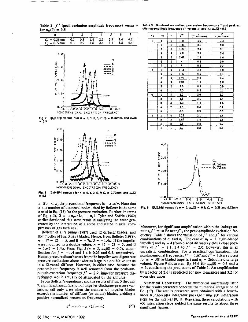
Table 2 f ° (peak-excitation-amplitude frequency) versus n
for uoo(0) = 0.5n l 2 3 4 5 6 7
C, = 0.36mm 0.3 0.8 1.4 2.1 2.9 3.6 4.2
C, = 0.72mm 03 0.9 1.6 2.4 3.1 3.8 4.4
Fig. 7• , 0.5
4.0] n
NONDIMENSIONAL EXCITATION FREQUENCY
1_1(0.9b')1 versus ffor n -- O, 1, 3, 5, 7; C, ,, 0.36ram, and u_0)
Fig. 8
,- 0.5
2.5n
--- 12.0 jh _ eeeee 3
0.5
0.0 ................... , ................................ _.....-4.0-2.0 0.0 2•0 4.0 6.0 8.0 10.0
NONOIMENSIONAL EXCITATION FREQUENCY
I_,(0.95)Iversusfforn = 0,I,3,5,7;C, = 0.72mm, and u_0)
n. If n_ < n 2 the precessional frequency is - nj_/n. Note thatn, the number of diametral nodes, cited by Bolleter is the same
n used in Eq. (13) for the pressure excitation. Further, in termsof Eq. (13), fi = ±nl_/tn= - n21. Tyler and Sofrin (1962)earlier developed this same result in analyzing the noise gen-
Table 3 Dominant normalized precession frequency f * and peak-ex-citation-amplitude frequency f ° versus n, and n=; U,e(0)= 0.5
Fig. 9
nl n2 n I +
8 1 7 1.14
2 6 1.33
3 5 1.60
4 4 2.0
5 3 2.67
6 2 4
7 1 8
7 1 6 1.16
2 5 1.40
3 4 1.75
4 3 2.33
S 2 3.5
6 1 7.0
6 1 6 1.2
2 4 1.6
3 3 2.0
4 2 3.0
S 1 6.0
5 1 4 1.25
2 3 1.67
3 2 2.5
I* 11 _o
I" /*(Co=o.semm.) (C,=O.T*_mm)
4.2 4.4
3.6 3.8
2.9 3.1
2.1 2.4
1.4 1.6
0.8 0,9
0.3 0.3
3.6 3.8
2.9 3.1
2.1 2.4
1.4 1.6
0.8 0.g
0.3 0.3
2.9 3.1
2.1 2.4
1.4 1.6
0,8 0.9
0.3 0.3
2.1 2.4
1.4 1.6
0.8 0.9
0.3 0.3
4.0"
_30
--0.36mm
< 0.72mm
_2.0"
0.0 .............................................-4,0-2.0 0.0 2.0 4.0 "6_0
NONOIMENS[ONAL EXCITATION FREQUENCY
1_l(O.95)lvereusf;n = 3, u_O)= 0.5;_ = 0._snd0.72mm
erated by the interaction of a rotor and starer in axial com-pressors of gas turbines. Moreover, for significant amplification within the leakage an-
Bolleter et al.'s pump (1987) used 12 diffuser blades, andthe impeller of Fig. 3 has 7 blades. Hence, from Bolleter (1988),n = 17 - 121 = 5, andfi = -7_/5 = -1.4oL If the impellerwere mounted in a double volute, n = 17 - 21 = 5, and
= 7_/5 = 1•4_. From Fig. 5 (n = 5, u_(0) = 0.5), ampli-fication for f = -1.4 and 1.4 is 0.23 and 0.5, respectively.Hence, pressure disturbances from the impeller would generatepressure oscillations about twice as large in a double volute asin a 12-vaned diffuser• However, in either case, because the
predominant frequency is well removed from the peak-am-plitude-excitation frequency f" = 2.9, impeller pressure dis-turbances would actually be attenuated by the annulus.
From Boileter's equations, and the results of Figs. 5 through7, significant amplification of impeller-discharge-pressure var-iations will only arise when the number of impeller blades
exceeds the number of diffuser (or volute) blades, yielding apositive normalized precession frequency.
.f+ =nl/n=n_/(n_-n2) (27)
nulus, f + must lie near f', the peak-amplitude excitation fre-quency. Table 3 shows the variation off + and f* for various
combinations of nt and n2. The case of n_ = 8 (eight-bladed
impeUer) and n2 = 4 (four-bladed diffuser) yields a close prox-imity of f" = 2.1, 2.4 to f* = 2.0; however, this is an
unrealistic combination. For a practical configuration, the
nondimensionalfrequenciesf + = 1.67andf* = 1.6 are closest
for n_ = 5(five-bladed impeller) and n2 = 2(double-dischargevolute). Figure 9 illustrates 1_(.95)1 for U_o(0) = 0.5 and n
= 3, confirming the predictions of Table 3. An amplification
by a factor of 2.6 is predicted for new clearances and 3.2 forworn clearances.
Numerical Uncertainty. The numerical uncertainty issue
for the results presented concerns the numerical integration of
Eq. (17). The results presented were obtained with a fourth-order Runge-Kutta integrator package using 200 integrationsteps for the interval [0, 1]. Repeating these calculations with
400 integration steps yielded the same results to about three
significant figures.
66 1 Vol. 114, MARCH 1992 Tr_m:_P,in.e _ the, t,l_ll/ll="

Summary and Conclusions
An analysis has been developed and results presented forthe pressure oscillations in the leakage annulus between ashrouded pump impeller and its housing. These pressure os-cillations are driven by a circumferential variation of the im-
peller discharge pressure which can precess either in the sameor opposite to the direction of rotation. The circumferentialvariation can be modeled with a Fourier decomposition with
each mode having n diametral nodes across the impeller. The
peak-pressure oscillations within the impeller are predicted tooccur near the exit wearing-ring seal in association with acentrifugal-acceleration-mode response of the fluid within the
annulus (Chiids, 1988, 1990b). The peak-amplitude-excitationfrequency increases linearly with n. Using Bolleter's (1988)work which provides a dependency of n and the precessionalfrequency on the number of impeller (hi) and diffuser (n2)blades, situations are presented which can yield large ampli-fications (or significant attenuation) of impeller discharge var-iations. The occurrence and nature of the pressure oscillationsare shown to depend on: (a) the tangential-velocity ratio ofthe fluid entering the seal, (b) the order of the Fourier coef-ficient, (c) the closeness of the precessional frequency of the
rotating pressure field to the first natural frequency of the fluidannulus, and (d) the clearance of the wearing-ring seal.
The present results suggest an explanation for the internalmelting observed on SSME HPFTP seal parts. However, given
liquid hydrogen's significant compressibility, a more complete
analysis, including fluid compressibility, is in order.
Bolleter, U., Wyss, A., Wehe, Z., and Stiirchler, R., 1987, "Measurementof Hydrodynamic Interaction Matrices of Boiler Feedpump Impellers," ASMEJournal of Vibrations, Stress, and Reliability in Design, Vol. 109, pp. 144-15 I.
Bolleter, U., 1988, "Blade Passage Tones of Centrifugal Pumps," Vibrations,Vol. 4, No. 3.
Childs,D., 1987,"Fluid-Structure InteractionForcesat Pump-Impeller*ShroudSurfaces for Rotordynamic Calculations," Rotating Machinery Dynamics, Vol.II, ASME 1987, pp. 581-593.
Childs,D., 1989, "Fluid-StructureInteraction Forcesat Pump-Impeller-ShroudSurfaces for Rotordynamic Calculations," ASME Journal of Vibration, Acous-tics, Stress, and Reliability in Design, Vol. 111, July 1989, pp. 216-225.
Childs, D., 1990a, "Fluid-Structure Interaction Forces at Pump-Impeller-Shroud Surfaces for Axial Vibration Analysis," accepted for publication inASME Journal of Vibration and Acoustics, May 1990.
C'hilds,D., 1990h, "Centrifugal-Acceleration Modes for IncompressibleFluidin the LeakageAnnulus Between A Shrouded Pump Impeller and Its Housing,"accepted for publication in ASME Journal of Vibration and Acoustics, May1990.
Hirs, G., 1973, "A Bulk-Flow Theory for Turbulence in Lubricant Films,"ASME Journal of Lubrication Technology, pp. 137-146.
Tyler, M. J., and Sofrin, T. A., 1962, "Axial Compressor Noise Studies,"SAE Trans., Vol. 70, pp. 309-332.
Journal of Fluids Engineering MARCH 1992, Vol. 114 1 67


\
GO
J

PA_E _._NK NOT F_LIVI_D.o°
111
N94- 27379
ABSTRACT _C _ _- _/
Compressibility Effects on Rotor Forces in the Leakage Path between a Shrouded
Pump Impeller and Its Housing. (August 1993)
Nhai The Cao, B.S., Texas A&M University
Chair of Advisory Committee: Dr. Data Childs
J
A modified approach to Childs' previous work (1989,1992) on fluid-structure
interaction forces in the leakage path between an impeller shroud and its housing is
presented in this paper. Three governing equations consisting of continuity, path-
momentum, and circumferential-momentum equations were developed to describe the
leakage path inside a pump impeller. Radial displacement perturbations were used to
solve for radial and circumferential force coefficients. In addition, impeller-discharge
pressure disturbances were used to obtain pressure oscillation responses due to
preeessing impeller pressure wave pattern. Childs' model was modified from an
incompressible model to a compressible barotropie-fluid model (the density of the
working fluid is a function of the pressure and a constant temperature only). Results
obtained from this model yielded interaction forces for radial and circumferential force
coefficients. Radial and circumferential forces define reaction forces within the
impeller leakage path.
An acoustic model for the same leakage path was also developed. The
convective, Coriolis, and centrifugal acceleration terms are removed from the
compressible model to obtain the acoustics model. The compressible model is
compared with the incompressible model and the acoustic model. A solution due to
impeller discharge pressure disturbances model was also developed for the
compressible and acoustic models. The results from these modifications are used to
determine what effects additional perturbation terms in the compressible model have
on the acoustic model.
The results show that the additional fluid mechanics terms in the compressible

, model cause resonances (peaks) in the force coefficient response curves. However,
these peaks only occurred at high values of inlet circumferential velocity ratios,
Uoo(O)> 0.7. The peak pressure oscillation was shown to occur at the wearing ring
seal. Introduction of impeller discharge disturbances with n = 11 diametral nodes
showed that maximum peak pressure oscillations occurred at nondimensional precession
frequencies (f = D_/co where co is the running speed of the pump) of f = 6.4 and f
- 7.8 for this particular pump. Bolleter's results suggest that for peak pressure
oscillations to occur at the wearing ring seal, the nondimensional excitation frequency
should be on the order of f = 2.182 for n -- I I. The resonances found in this
research do not match the excitation frequencies predicted by Bolleter. At the
predicted peak excitation frequencies given by Bolleter, the compressible model shows
an attenuation of the pressure oscillations at the seal exit.
-_The compressibility _of_he fluid :cioes 'not have a significant influence on the
model at low values of nondimensional excitation frequency. At high values of
: nondimensional frequency, the effects of compressibility become more significant. For
the acoustic analysis, the convective, Coriolis, and centrifugal acceleration terms do
affect the results to a limited extent for precession excitation and to a large extent for
a pressure excitation when the fluid operates at relatively high Mach numbers.

V
To the memory of my grandfather, Cao Van Tac.

vi
ACKNOWLEDGE_fENTS
I would like to express my thanks to Dr. Dara Childs for his countless hours
of help, instruction, and support. I would also like to thank Dr. Childs for providing
the opportunity for me to work on this project.
Dr. Tae Wong Ha, Dr. Zhou Yang, and Dr. Alan Duncan have provided much
needed intellectual stimulation, and my thanks go out to them for their tireless effort.
Thanks also go out to Mr. Andy Ma, Mr. Gabriel Rodriguez, Mr. Patrick
Hardin, and everyone else who sacrificed their sanity by providing the computer
resources used in preparing this report.
Finally, Mr. Kenneth Kmiec, Mr. Steven Suh, Mr. Monte Williams, and Mr.
Max Gibbs deserve special thanks for putting up with the Coke cans and all the other
stuff.

vii
TABLE OF CONTENTS
Page
ABSTRACT ......................................... m
DEDICATION ....................................... v
ACKNOWLEDGEMENTS ............................... vi
LIST OF FIGURES ..................................... ix
xiLIST OF TABLES .....................................
NOMENCLATURE .................................... xii
CHAPTER
I INTRODUCTION ........... • ..........
II LITERATURE REVIEW ............................
III OBJECTIVES ...................................7
V BULK FLOW MATHEMATICAL MODEL ................. 10
5.1 General Governing Equations ....................... 10
5.2 General Perturbed Equations - Nondimensionalization and
Perturbation Analysis .............................. 135.2.1 Zeroth Order Solution ...................... 13
5.2.1.1 Zeroth-Order Equations ............... 14
5.2.1.2 Zeroth-Order Solution ................ 15
5.2.1.3 Zeroth-Order Results ................. 15
5.2.2 First-Order Equations ...................... 20
VI FIRST ORDER EQUATIONS AND SOLUTIONS FOR GENERAL
PERTURBED COMPRESSIBLE MODELS ................. 22
6.1 Precession Excitation: General-Perturbation Model .......... 22
6.1.1 Boundary Conditions ....................... 25
6.1.2 First-Order Results ........................ 25
6.2 Pressure Excitation ............................. 33
6.2.1 First-Order Equations ...................... 33
6.2.2 Boundary Conditions ....................... 35
IV GEOMETRIC AND OPERATING CHARACTERISTICS ........ 8

VIII
CHAPTER Page
6.2.3 First Order Solution ........................ 35
6.2.4 First-Order Results ......................... 36
VII FIRST ORDER EQUATIONS AND SOLUTIONS FOR ACOUSTIC
MODELS ...................................... 43
7. I Precession Excitation Model ........................ 43
7.1.1 First Order Equations ....................... 437.1.2 First-Order Precession Excitation Solution .......... 44
7.1.3 First-Order Results ......................... 46
7.2 Pressure Excitation Model 46
7.2.1 First-Order Equations ....................... 46
7.2.2 First-Order Pressure Excitation Solution ............ 53
7.2.3 First-Order Results ......................... 53
VIII SUMMARY AND CONCLUSIONS ...................... 57
REFERENCES ....................................... 59
APPENDIX A ........................................ 60
APPENDIX B 62
APPENDIX C ........................................ 63
APPENDIX D ........................................ 64
VITA ............................................. 65

ix
LIST OF FIGURES
FIGURE
1
2
3
Page
Impeller stage and surface geometry ..................... 2
Nominal configuration of conventional water impeller ........... 4
Nondimensional force coefficients for the conventional impeller (a)circumferential-force coefficient, (b) radial-force coefficient ....... 4
4 SSME HPFTP first impeller stage ....................... 9
5 Zeroth-order pressure p distribution along leakage path for
compressible and incompressible models for u_0) = 0.7 ....... 17
6 Zeroth-order path velocity (U_o) distribution along leakage path forcompressible and incompressible models for u_0) -- 0.7 ....... 18
7 Zeroth-order circumferential velocity distribution along leakage path forcompressible and incompressible models for u0o(0) ffi 0.7 ....... 19
8 Radial response for compressible and incompressible models forprecession excitation for u0o(0) - 0.7 .................... 26
9 Circumferential response for compressible and incompressible modelsfor precession excitation for u_0) - 0.7 ................. 27
10 Amplitude and phase plot of nondimensional pressure p for precessionalexcitation of compressible model at f - 0.1 ............... 29
11 Amplitude and phase plot of nondimensional pressure p for precessionalexcitation of compressible model at f - 0.8 ............... 30
12 Amplitude and phase plot for precessional excitation for path velocityu,1 for compressible model at f - 0.1 ................... 31
13 Amplitude and phase plot for precessional excitation for path velocityu,_ of compressible model at f -- 0.8 and u_0) - 0.7 ......... 32
PageFIGURE
14 Nondimensional force response of compressible and incompressible
models for precessional excitation for extended frequeney range .... 34
15 Pressure oscillation response of compressible model for pressure
excitation for n -- 11 at leakage path exit (s = 1) and ueo(0) = 0.7 37
16 Amplitude and phase plot for pressure oscillation of compressible model
inside impeller leakage path at f = 6.4 for n -- 11 and Ueo(0) -- 0.7. 39
17 Amplitude and phase plot for pressure oscillation of compressible model
inside impeller leakage path at f - 7.5 for n = 11 and ueo(0) = 0.7. 40
18 Pressure oscillation response for pressure oscillation of compressible
model with multiple n and Uoo(0) = 0.7 .................. 42
19 Radial response for acoustic and compressible models for precessional
excitation for ueo(0) = 0.7 ...... • ................... 47
20 Circumferential force response for acoustic and compressible models for48
precessional excitation and ueo(0) -- 0.7 ..... , • , ..........
21 Force response coefficient for acoustic and compressible models at49
extended frequency ratios ....... . ;, , ................
22 Amplitude and phase plot of nondimensional pressure vs. path length ofcompressible model at f - 11.5 for ueo(0) = 0.7 . ........... 50
23 Pressure mode shape and phase plot of acoustic model vs. path length51
/ 12.0 fo ueo(O) 0 7 • •at - r = . -=..-... ..,...,. ....-.''
24 Acoustic response for impeller discharge pressure excitation for n = 11for Ueo(0) = 0.7 .......... , ...................... 52
25 Pressure response of incompressible, compressible, and acoustic model
for impeller discharge pressure excitation for n = 1 for ueo(0) = 0.7 55
26 Pressure response for pressure excitation for multiple n ......... 56

xi
LIST OF TABLE_
TABLEPage
(nz - nz) for various combinations of multiples of impeller blades and38
2 Expected peak nondimensional frequency ratios, f or, {n/(nl - n_)}, forvarious combinations of multiples of impeller blades and vanes ....
38

xii
NOMENCLATURE
A3e, A4o
b = Vi/Ro_
C.
Ci
C.
h = H/Ci
H
L
L,
M
I'/
P
p = P/PVi2
p,(0,t)
p,(O,0
R
-- 2HUJv
r -
S
s = S/L,
T = L,/V i
t
u, = U./Vl
At,, A2,, A3,, A4,,AIo, A20,
coefficients introduced in Eq. (32-33)
nondimcnsional velocity ratio
discharge coefficient for the exit wearing ring seal (Eq. 11)
initial (s=0) clearance (L)
exit (s = 1) clearance (L)
nondimensional frequency ratio
nondimensionalizcd clearance
clearance between impeller shroud and housing (L)
path length (L)
leakage path length (L)
Mach number - fluid velocity/acoustic velocity
difference in number of impeller blades and diffuser vanes
fluid static pressure (F/L')
dimensionless pressure
dimensionless inlet supply pressure (s=0)
dimensionless exit pressure (seal exit)
radial coordinate (L)
initial radial coordinate (s=0)
Reynolds number defined in Equation (8)
nondimensionalized radial coordinate
Path coordinate (L)
nondimensionalized path length
representative transit time for fluid traversing
the leakage path (T)
Time (T)
nondimensionalized path fluid velocity

,o,
Xlll
U,,Uo
Vi
E
k,,X,
a,,a,
p
T=o_t
T_
I",,_rr
0
fl
v
nondimensionalized circumferential fluid velocity
path and circumferential velocity of fluid (L/T)
initial (s=0) path fluid velocity
perturbation parameter
Friction factor definitions defined in Eq. (19)
Wall friction factor defined in Eq. (19)
Fluid viscosity (F-T/L 2)
Fluid density (m/L 3)
nondimensionalized fluid density
nondimensionalized time
Wall shear stress (F/L 2)
Shear stress on stator and rotor surfaces (F/L 2)
Circumferential coordinate
Rotor angular velocity (T "1)
Shaft whirl angular velocity (T "_)
Inlet loss coefficient
Kinematic viscosity (L2T _)
Subscripts
r, s
z, 0
0, 1
Rotor and stator
Axial and circumferential directions
Zeroth and fu'st-order perturbations


CHAPTER I
INTRODUCTION
In the past, wear-ring seals used on the SSME I-IPFFP (Space Shuttle Main
Engine High Pressure Fuel Turbopump) made from KEL-F plastic came back after
operation revealing highly unusual characteristics. Despite being in constant contact
with liquid hydrogen, post-test inspection showed that interior points in the stator
element had melted and resolidified. The material used in the seal stator has poor heat
conduction properties and high internal hysteretic damping. Pressure oscillations
adjacent to the seal may be a source of cyclic stress producing hysteretic losses. This
investigation will examine the pressure oscillations which may cause cyclic stresses in
the leakage path between the impeller shroud and its housing. Possible sources of
excitation causing the seal to melt and resolidify will be investigated.
For this project, an analysis will be performed for a bulk flow model of the
leakage path between a pump impeller shroud and a housing along the front side of the
impeller, from inlet to discharge (Fig. 1). Simply defined, a bulk flow model
considers only the average of the velocity distribution across the flow field. The
research will be an extension of analyses performed previously by Childs (1989, 1992)
for a shrouded pump impeller and its housing.
The working fluid will be modelled as a barotropic fluid in this analysis, instead
of an incompressible fluid, to account for fluid compressibility. The density and
viscosity of barotropic fluids depend only on the local pressure and are independent of
temperature. This assumption is reasonable for most cryogenic fluids, where viscosity
is low and effects of viscous heating are negligible. The properties of the working
fluid, i.e., density and viscosity, will be implemented into a new analysis by using a
general 32-term, thermodynamic, equations-of-state program, MIPROPS (McCarty,
1986, modified by San Andres, 1991).
This paper is modelled after the ASME Journal of Ttibology.

"3
ZMP£LLER SHROLID
SEAL _, _/ll J lK5
Z
Figure 1 - Impeller stage and surface geometry

CHAPTER II
LITERATURE REVIEW
Childs (1989) performed a bulk-flow analysis for the leakage path between an
impeller shroud and a pump housing. Three governing equations of motion were
derived for a bulk-flow model to represent incompressible fluid flow in the leakage
path of a conventional water pump impeller. Three equations, consisting of a
continuity equation, a path-momentum equation, and a circumferential-momentum
equation, were used to solve for rotordynamic forces due to a precessional excitation
of the rotor.
Childs used a perturbation expansion in the eccentricity ratio of the governing
equations of fluid motion for small motions about a centered impeller position yielding
a set of zeroth and first-order governing equations. A zeroth-order solution was
obtained by an iterative procedure to define the leakage, pressure, and circumferential-
velocity distribution. Using a perturbed clearance function due to a radial displacement
perturbation, Chiids evaluated the first-order model at several inlet circumferential
velocity conditions to obtain the first-order perturbed solutions. First-order
perturbation results provided rotordynamic coefficients (direct and cross-coupled
stiffness, damping, and mass) and lateral reaction forces for the model. Childs'
predictions for the impeller of Fig. 2 are shown in Fig. 3. The predicted radial and
circumferential force coefficients are shown versus the nondimensional precessional
frequency for nondimensionalized inlet circumferential velocities of uoo(0) = 0.5, 0.6,
and 0.7. Nondimensional precessional frequency is the ratio of the impeller precession
frequency, t'/, to its running speed, _. The graphs showed a considerable "dip", or
resonance, in the radial and circumferential force response coefficients at higher values
of Uoo(0). The radial and circumferential force coefficients represent the
nondimensionalized reaction forces acting on the impeller face due to impeller
precession. Childs showed that the centrifugal acceleration terms in the momentum
equations produced the "dip" in the results. By removing the

01MENSION$ IN
62 MILLIM_ T[ RS
i 57
i I i
._, / ///j _ v//j
Figure 2 - Nominal configuration of conventional water impeller
• • (Qll_llf|_mdlK I#_[LU[II
,3 ,. ut41(O) I 45 ....
<_<,_.. A r\ _L,o,o). • • --
++ "_. +\ .,,,w, o,---
-o \_ \-_-':'_._
-., \/ "'"-_-,Z "_'-.
-o |-i.5 -I o. 5 o .s I L$ 2 2.S
-I.3lS-.'15 *.25 .;_I .?$ |.rJ t.'lmJ IP..Z5
f.a/u
.S
.4
+3
.2
,I
_So
-.2
**J
-.4
-.S
(Odm[I¢l'lOll_ II.I@IUJ_
_lqW[O) ,, OS ....
tllm(lU- • • --
_le(O)w 0.7 -----
-J.S -1 -.5 0 +S 1 1.5 Z I. 'c
I lS-.lS -.IS .IS _J |.m l.?s ?..2S
f-qv
. T :
Figure 3 - Nondimensional force coefficients for the conventional impeller (a)
circumferential-force coefficient, (b) radial-force coefficient

5
centrifugal acceleration term from the path-momentum equation, the "dips" in the plots
were eliminated.
Bolleter (1988) presents a relationship between the difference (n) in the number
of impeller blades (n 1) and diffuser vanes (n,) and the precessional frequency for
pressure pulsations in an impeller leakage path. Various combinations of impeller
blade and diffuser vane number causing vibrations and pressure pulsations in the
impeller are described. The relationship presented by Bolleter states that a pressure
pattern develops with n = I n I - n, [ diametral nodes around the impeller exit. The
precession velocity of the pressure oscillation is no_J([ nl - n_b. For example, an
impeller with n_ = 11 blades and n: = 6 diffuser vanes would have amplifications of
the pressure oscillations at frequencies of multiples of 11c0/([11 - 6 b--2.2_.
Childs (1992) performed an analysis similar to (Childs, 1989) incorporating the
effects of different numbers of impeller blades and diffuser vanes for the bulk flow
model using excitations due to discharge-pressure oscillations instead of orbital motion.
This analysis considered the harmonic response of flow within the annulus due to
variations in the discharge pressure of the impeller. This analysis also compared the
effect on the response of the pressure oscillation due to different numbers of pump
impeller blades and diffuser vanes. Zeroth and first-order perturbation equations were
also derived for this analysis. However, the first order perturbations in this analysis
were excited by discharge-pressure perturbations instead of impeller precession. The
impeller discharge excitation was defined as a precessing harmonic pressure oscillation
with n nodes and a precessional frequency of _.
Results from the analysis due to perturbed flow in the leakage path caused by
oscillations in the impeller discharge pressure show that the peak pressure oscillation
occur near the exit ring seal. The pressure oscillations from the impeller were shown
to depend on the circumferential velocity of the fluid entering the seal, the Fourier
coefficient, n, and the relative closeness to the first resonant frequency of the fluid to
the peak precessional frequency of the rotating pressure field. Note that n represents
both the Fourier coefficient used by Childs and Bolleter's n -- I nz - n_l.

6
Acoustic modes are produced by the interaction of fluid inertia and
compressibility. Thompson (1988) explains that the wave equation, the fundamental
equation of acoustics, is obtained by assuming that the convective acceleration terms
are negligible compared with the temporal acceleration terms. For ordinary acoustic
analysis, Thompson states that this assumption is "highly satisfactory" for fluid flow
characterized by a low Mach number, typically M 2 ,, 0.1. By removing the convective,
Coriolis, and centrifugal acceleration terms from a modified general perturbation
(compressible) version of Childs' model, a similar wave equation can be obtained.
This resulting equation, in theory, can be used for an "acoustic" analysis of the flow
fields. °_
San Andres (1991) developed a solution procedure for a model of fluid flow in
turbulent hydrostatic bearings and annular seals operating with cryogenic barotropic
fluids. He used a 32-term equations-of-state program provided by N'BS Standard
Reference Data Base for prediction of the properties of LI-I 2, LO2, LN2, and other_ ' : -i_ i 2 _-::: -:_ " :
fluids at different pressures and temperatures. The code, MIPROPS, delivers fluid
properties which are used in the analysis procedure, in addition to obtaining the fluid
properties from MIPROPS for use in a compressible model, San Andres also
considered the properties of the working fluid as a linear function of pressure. From
his results, San Andres found that for highly compressible fluids, such as liquid
hydrogen, the barotropic properties model based on an equation of state gave accurate
leakage and force response for bearings and seals with a large pressure differential.

7
CHAPTER III
OBJECTIVES
This research will introduce compressibility of the working fluid in the leakage
path as an extension to the analyses performed by Childs (1989, 1992). The results
will provide information concerning the relationship between an incompressible, a
compressible, and an acoustic model with liquid hydrogen as the working fluid. The
results will also provide information regarding the cause of the unusual behavior
exhibited by the KEL-F plastic rotor element and verify the validity of Thompson's
assessment concerning the effects of fluid mechanics and acoustics. This research
project will also analyze the effects of the centrifugal acceleration modes and acoustic
modes of a barotropic fluid in the leakage path between a shrouded pump impeller and
its housing.
The results obtained from a compressible-flow model will be compared with
the results of an incompressible model. The compressible-flow model will also be
reduced to an acoustics model, the results of which will be compared to the
compressible-flow model. This comparison will be performed for two different
perturbation excitations: (a) a precessional excitation involving an orbital motion of
the rotor, and (b) a pressure oscillation excitation, involving perturbation of the
discharge or inlet pressure of the leakage path. The geometric and operating
characteristics of the first stage impeller of the SSME HPFTP will provide the
parameters used for the governing equations.
A bulk-flow model will be developed and used to simulate the leakage path
inside the first impeller stage of the Space Shuttle Main Engine Turbopump. Results
from the computation should indicate if any interaction exists between acoustic and
centrifugal acceleration modes, and the influence of fluid mechanics terms (convective,
Coriolis, or centrifugal acceleration terms) on acoustic modes.
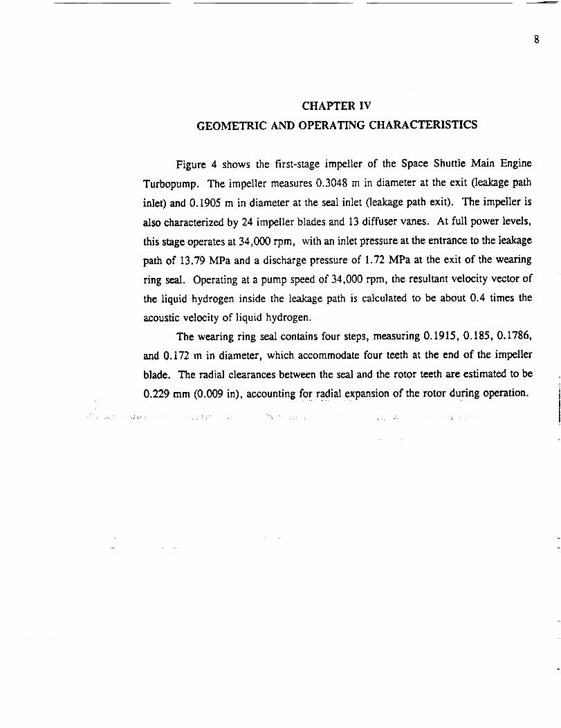
8
CHAPTER IV
GEOMETRIC AND OPERATING CHARACTERISTICS
Figure 4 shows the first-stage impeller of the Space Shuttle Main Engine
Turbopump. The impeller measures 0.3048 m in diameter at the exit (leakage path
inlet) and 0.1905 m in diameter at the seal inlet (leakage path exit). The impeller is
also characterized by 24 impeller blades and 13 diffuser vanes. At full power levels,
this stage operates at 34,000 rpm, with an inlet pressure at the entrance to the leakage
path of 13.79 MPa and a discharge pressure of 1.72 MPa at the exit of the wearing
ring seal. Operating at a pump speed of 34,000 rpm, the resultant velocity vector of
the liquid hydrogen inside the leakage path is calculated to be about 0.4 times the
acoustic velocity of liquid hydrogen.
The wearing ring seal contains four steps, measuring 0.1915, 0.185, 0.1786,
and 0.172 m in diameter, which accommodate four teeth at the end of the impeller
blade. The radial clearances between the seal and the rotor teeth are estimated to be
0.229 mm (0.009 in), accounting for radial expansion of the rotor during operation.
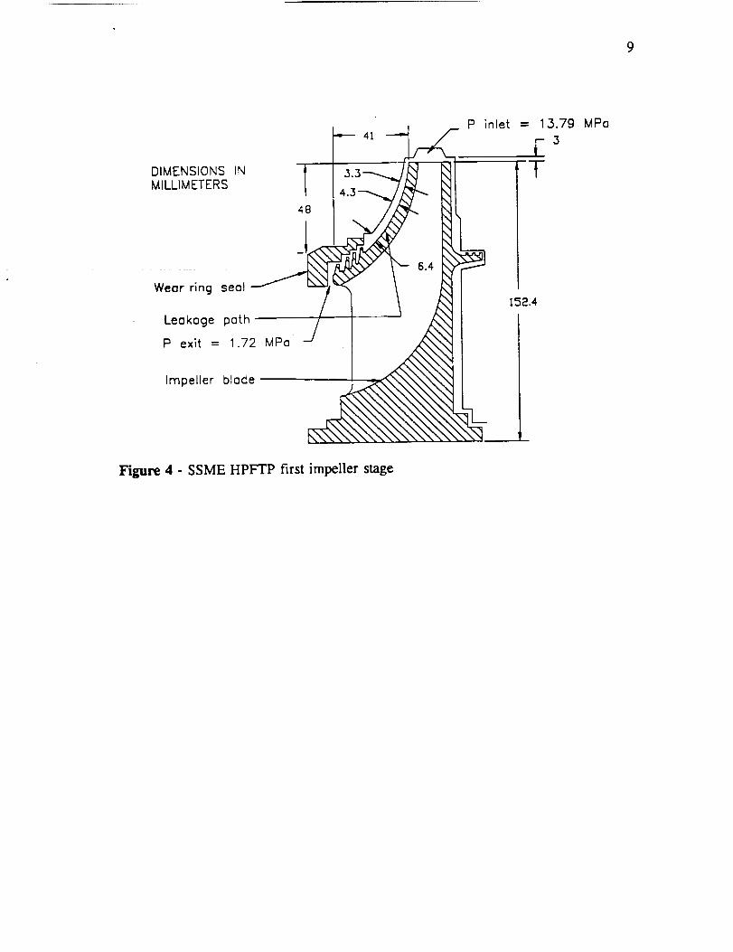
9
DIMENSIONS INMILLIMETERS
Wear ring s_:l h
Leakage
P exit = 1.72 MPo
Impeller blade
,! 3.3--._ _ T
Figure 4 - SSME HPFTP first impeller stage

10
CHAPTER V
BULK FLOW MATHEMATICAL MODEL
Childs' governing equations will be modified for this project to reflect a bulk
flow model operating with'a barotropic fluid. As in Childs' analysis, these equations
will be nondimensionalized and perturbed to yield zeroth and first-order governing
equations.
5.1 General Governing Equations
Using the approach taken by Childs (1989), the governing equations are:
• Continuity Equation
OpH O, U + 1 O, U" H aR (1)
• Path-Momentum Equation
_HaP = . Ug dR+_, ÷%+p + (2)
• Circumferential-Momentum Equation
Jave auou_ auo uou,aR_HaP _ _o_ +mRao +_°'+P"[--&-÷ooR osv,÷ R -_)
(3)
An additional governing equation is obtained by using MIPROPS to obtain the
properties of liquid hydrogen.
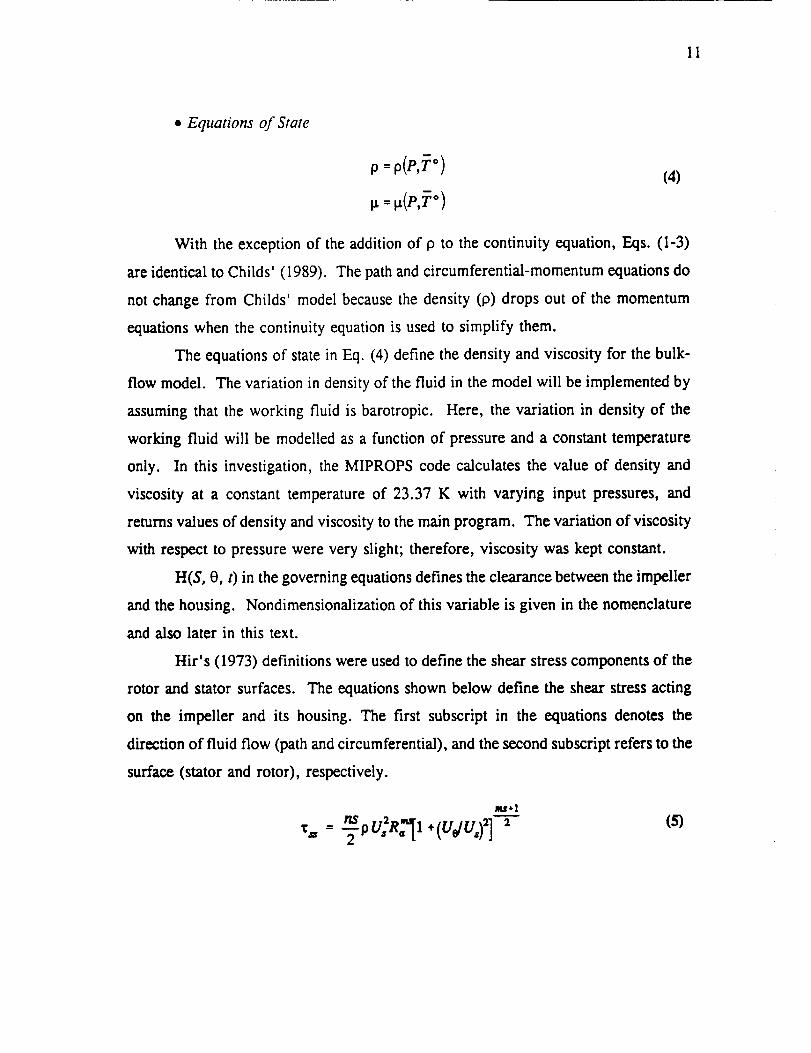
I1
• Equations of State
P: (4)
With the exception of the addition of p to the continuity equation, Eqs. (1-3)
are identical to Childs' (1989). The path and circumferential-momentum equations do
not change from Childs' model because the density (p) drops out of the momentum
equations when the continuity equation is used to simplify them.
The equations of state in Eq. (4) define the density and viscosity for the bulk-
flow model. The variation in density of the fluid in the model will be implemented by
assuming that the working fluid is barotropic. Here, the variation in density of the
working fluid will be modelled as a function of pressure and a constant temperature
only. In this investigation, the MIPROPS code calculates the value of density and
viscosity at a constant temperature of 23.37 K with varying input pressures, and
returns values of density and viscosity to the main program. The variation of viscosity
with respect to pressure were very slight; therefore, viscosity was kept constant.
H(S, 0, t) in the governing equations defines the clearance between the impeller
and the housing. Nondimensionalization of this variable is given in the nomenclature
and also later in this text.
Hir's (1973) definitions were used to define the shear stress components of the
rotor and stator surfaces. The equations shown below define the shear stress acting
on the impeller and its housing. The first subscript in the equations denotes the
direction of fluid flow (path and circumferential), and the second subscript refers to the
surface (stator and rotor), respectively.
m.f*l
,: (5)
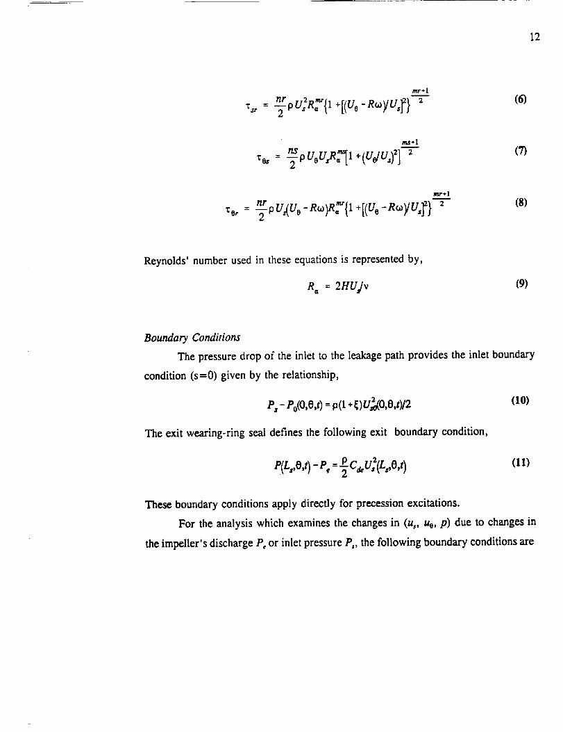
12
mr÷l
(6)
ma÷ l
ns
_o= = "_PUoU_I +(U_Ua)2] 2(7)
mr÷l
_ nr -R_)RT{1 -Ro)/U,_}2ou/u. +[(uo(8)
Reynolds' number used in these equations is represented by,
R a = 2HUs/v (9)
Boundary Conditions
The pressure drop of the inlet to the leakage path provides the inlet boundary
condition (s=0) given by the relationship,
P, - Po(O,O,t)= p(1 +_)U_O,O,t)/2 <10)
The exit wearing-ring seal defines the following exit boundary condition,
P(L,,O,t)-Pe=2CeeU_(Ls,O,t) (11)
These boundary conditions apply directly for precession excitations.
For the analysis which examines the changes in (u,, ue, p) due to changes in
the impeller's discharge P, or inlet pressure P,, the following boundary conditions are

13
stated for the inlet and exit, respectively,
e,(o,t)- Po(O,O,t)=p(l÷_)u_o,o,t)/2 (12)
P(L,,e,,)-P,<O,,I (13)
Eqs. (12-13) differ from Eqs. (10-11) because P, and P, are now also functions of
time.
5.2 General Perturbed Equations - Nondimensionalization and Perturbation
Analysis
Introducing the following variables into Eqs. (1-8),
u,=u,/v,, uo=ujR,,,,, p=P/pV?,
h = HIC i, s =SIL s, r = RIR_
"_= _t, b = V/Ricz, T= LJV l
= P/Pi
(14)
yields nondimensional governing equations.
The perturbation variables used to obtain zeroth and first-order equations are
defined by,
us=uso +¢usl ' h=ho +eht' ISfPo+¢Pt (15)
uo = Uoo + eUot, P =-DO+ cPl
where ¢ is the perturbation coefficient to be defined separately below for precession
and discharge-pressure excitation.
5.2.1 Zeroth Order Solution
The zeroth-order equations are the same for the precession and exit-pressure
excitations.

14
5.2. I. 1 Zeroth-Order Equations
The path and circumferential velocity distribution and the leakage rate for a
centered impeller position are defined by the following zeroth-order governing
equations.
• Continuity Equation
rhousoOo = 1 (16)
• Path-Momentum Equation
1 dPo du,o
Oo ds d_
1 dr(Uoo) 2 (os+Or)u_ °-T_T) ÷ 2
• Orcumferentiai-Momeniuin Equation "
2a,_o+2"_ +[o,{,.-,)+o:,.]--ods rds
{17)
(18)
where
• Equation of State
o, =(L,/'o)X,,o,. (L,mo)X,_÷1
_,_,_R.71+(u_/bu,o}_]-rmu'*I
Eq. (19) represents friction factor definitions for the stator and
respectively, introduced in Eqs. (5-8).
(19)
(20}
rotor surfaces,

15
5.2.1.2 Zcroth-Ordcr Solution
The zeroth-order continuity Eq. (16) can also be expressed as,
du_o_ [ l dho I dPo 1dr]- -Uso _ +_ +--_
(21)
This equation can be substituted into Eq. (17) to obtain
u r, ol rll-=-
+ (o,+ o) u_ (22)2
The governing zeroth-order equations now reduce to two governing equations,
consisting of Eq. (18) and Eq. (22). Eq. (20) defines p solely as a function ofp and
provides the density used in Eq. (18) and Eq. (22).
Boundary. Conditions
The inlet boundary condition for the zeroth-order pressure relationship can be
expressed from Eq. (10) as,
= P" -(1+_)y_o)po(O)p,v?
(23)
The zeroth-order solutions are obtained by solving Equations (18) and (22)
iteratively. An initial (s=0) fluid velocity V_ is estimated which then defines u,o(s).
A specified Uoo(O)and the calculated Po from Eq. (23) are used to numerically integrate
the zeroth-order equations (18) and (22) from the path entrance (s=0), to the path exit
(s= 1). The procedure is continued with revised values of V_ until convergence is
obtained between the prescribed and the calculated exit pressure.
5.2.1.3 Zeroth-Order Results
The zeroth-order results provide the mass flow rate through the leakage path.

16
The dischargecoefficient Cde used in this analysis was obtained by using the leakage
rate through the wearing ring seal. The leakage through the wearing ring seal of the
SSME HPFTP was calculated using a seal leakage code developed by Morrison et al.
(1983), and this value was used to calculate the discharge coefficient at specific
impeller operating conditions. The seal leakage code uses the geometry of the seal
and the operating conditions, i.e., inlet and exit pressures, viscosity, density, etc. to
calculate the leakage rate through the seal. Note that this seal leakage code treats the
working fluid as incompressible.
The seal leakage code yielded several mass flow rates for the prescribed
geometry and operating conditions, depending upon the pressure drop across the
impeller and the wearing ring seal. Several discharge coefficients were tested in the
model to match the flow rate through the impeller leakage path and the flow rate
through the seal. Once the two flow rates converged, the resulting C,_ was used in
the model as an exit restriction boundary condition. The mass flow rate through the
seal was found to be 1.6373 kg/s, with the resulting C,u being 7039.6, and inlet and
exit pressure of the seal being 8.101 MPa and 1.72 MPa, respectively. This pressure
drop across the seal represents about one third of the total pressure drop across the
entire impeller leakage path.
Zeroth-order pressure solutions for the incompressible and compressible models
are shown in Figure 5. The nondimensional path velocity along the leakage path is
given in Figure 6, and the zeroth-order circumferential path velocity is shown in
Figure 7. For the incompressible model, a mean value for the density of liquid
hydrogen inside the impeller leakage path was used to obtain the results shown.
The results of the compressible model vary only slightly from the
incompressible model for the zeroth-order solution. The pressure distribution across
the leakage path shows the same trend and approximately the same magnitude of
pressure drop, but not exactly the same inlet and exit pressure values. The C_, found
earlier provides the exit restriction for the seal and therefore is used for both models.
Because the incompressible model uses an average density along the leakage path, the
inlet and exit densities for the two models will be slightly different. This accounts for

17
-- '4"-- p(O)-;ncompressiiole
--_ p(O)--compressible
E
_ ! I I 1 I 1 I t 10.0 0.1 0.2 0.3 0.4 0.5 0.6 0.7 0.8 0.9
Nondimensional Path Length (s)
.0
Figure 5 - Zeroth-order pressure p distribution along leakage path for compressible
and incompressible models for u_o(0) = 0.7

18
-- "_-- us(O)-;ncornpressible
-_ us(O)-cornpressible
0 1.6-
(/1
>.
"_ 1.4 --0
Q_>
c-
E_ 1.2--n
E_
"_ 1.0
T" +,Q,E
E0 0.8--
Z
0.6I I I t i t I I
0.0 0.1 0.2 0.3 0.4 0.5 0.6 0.7 0.6
r
flJ
i'jf,i
/,'
/,t t/+t
//'/I,/
I
0.9
Nondimensionol Pofh Lengfh (s)
1.0
Figure 6 - Zeroth-order path velocity (u,o) distribution along leakage path forcompressible and incompressible models for Uoo(0) = 0.7
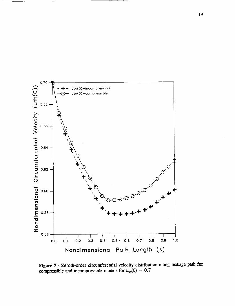
19
C.70 :
0
r-
:3 0.58-
Ow 0.56-
>
(3lg
E 0.64.-
k.Q)
:3 0.62-0I-
o
i
(3 0.60--EO
01E
E 0.58-im
"13E0
Z0.56
7
I -- 4=-- uth(0)--incompressible
_ uth(0)-compressible
0.0
\
I I I I I I 1 I I0.1 0.2 0.3 0.4 0.5" 0.6 0.7 0.8 o.g .0
Nondimensional Path Length (s)
Figure 7 - Zeroth-order circumferential velocity distribution along leakage path for
compressible and incompressible models for Uoo(0) = 0.7

20
the difference in the dimensionlesspressuremagnitudesshown in Figure 5. The
dimensionalpressuresat the inlet are almostexactly the samevalue, confirming the
inlet boundarycondition. As shownin Figure 6 andFigure 7, the zeroth-orderpath
velocity andthezeroth-ordercircumferentialvelocity arenot affectedsignificantly by
compressibility.
5.2.2 First-Order Equations
First-order governing equations define the path and circumferential velocity and
pressure distribution along the leakage path due to perturbed clearance function or
perturbed discharge-pressure.
First-order perturbation equations obtained by the perturbation expansion of Eq.
(14) are
• Continuiry Equation
+-;L _-- +ho_o-_- uoopo-_-j
ldr(u-,Toords_"°P°nl+uaf_°h°+u'°p_h°)=0
(24)
• Path-Momemum Equation
a_o as +uoIAz'+usIA3s+ _tA_ + Toou°°OUa + uso(gual = htAu (25)
+ Too rO0 osJ
• Circumferential-Momentum Equation
r R_ I_o_ + UelA2e + ustA_ + _3IA4e + Too +Too u00 auol -_]r aO + u_° =hrAle
(2O3

21
• Equation of State
a_ 1 d_ 1 8Pl a_ l d_ l apt a_ 1 _ d_ l apt
_7 dp as a_ _p a_ ao d_-_(27)
With the exceptions of A4, and A40, which are defined in the appendix, the parameters
At, , A2, , etc., in these equations can be found in Childs (1989).
The dependency of _ with respect to s, _', and 8 in Eq. (24-26) are eliminated
from the governing equations by applying the definitions of Eq. (27). The relationship
between _ and p in Eq. (27) was obtained from the results produced by MIPROPS.

22
CHAPTER VI
FIRST ORDER EQUATIONS AND SOLUTIONS FOR GENERAL
PERTURBED COMPRESSIBLE MODELS
This chapter provides the first order equations and solutions for precession
excitation and pressure excitation cases for the general perturbation (compressible)
models. Results for both excitation cases are presented using an inlet tangential
velocity of Uoo(O) = 0.7. The radial and circumferential-force coefficient response
curves represent the nondimensional reaction force acting on the impeller face in the
respective directions versus nondimensional frequency ratio, f.
For the first-order solution analysis, a separation of variable approach was used
to obtain complex ordinary differential equations. The resulting coupled equations
were integrated to obtain the nondimensional radial and circumferential force response
coefficients. The calculated results from the first-order precession excitation and the
pressure excitation of the general perturbed bulk flow model provide predictions which
can be used to qualify and quantify the effects of fluid compressibility in the model.
6.1 Precession Excitation: General-Perturbation Model
The precession excitation of the general perturbed model uses the perturbed
clearance function,
--htc(s,,)eos0 +hL,(s,,)sin0 (28)
as the excitation.
The theta dependency of Eqs. (24-26) can be eliminated by substituting the
following solution format
usz = uaccosO + ususinO
Pt =Plc era0 +p_in0
uei = uolccos0 ÷ uo_in0
t = t,c°sO* P . inO
into Eqs. (24-26), which yields six real equations.
(29)

23
Three complex equations in the independent variables s and x can be obtained
by introducing the complex variables
u l =us1c +ju, l`, ttel =uolc +juots, _ = 01c +JOt_ (30)
12x--Pie +JPu, hx =hl_ +jhts
These complex equations in the independent variables s and x are
I.°0o o,1, J_,, j,_T [1 aho + I aOo l.._U0ol_- --r-_'÷_"[_o_ _o_ ÷;-_ _: _+_ "_Tu ] _TC3hl UsoOhl_r dOt 012x+Usoa_= h, us°ah° + J_or oo]- ho 8x - ho asPo d121fir, Po _ ho2 as
(31)
1 a121
0o
(32)
_._. u0° igl/et] _--(33)r R i 0o
Since the equation of state is a function of pressure and a constant temperature only,
it can be modified as shown in Eq. (27) and used to remove the dependency of _ from
s in Eq. (31). Further simplification of Eqs.(33-35) can be made by using the
following definitions provided by Childs (1989)
(34)
(35)
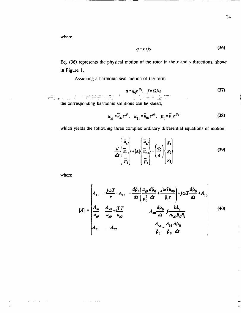
24
where
q =x+jy (36)
Eq. (36) represents the physical motion of the rotor in the x and y directions, shown
in Figure 1.
Assuming a harmonic seal motion of the form
q =qo ei_, f= t'2l_
the corresponding harmonic solutions can be stated,
(37)
a =u,:_, u_ =uete_, ._ =_:_' (3s)
which yields the following three complex ordinary differential equations of motion,
ua] gt
+pt ueiI= g2_,,j s,
(39)
where
[a]=
juTAll -_ -Al2
r
a __ a2__2+;T___rUsO UaO UaO
A3t A32
_dPof u_odPo .J_.Tuoo).joTd!o
A d_o. bL,
A4a A33 dPo
Po Po _
+Ar_
(40)

25
'tg2
g
dp0 +Jh0
dz.Al0
dsu, o
Gq
(41)
Elements used in Eqs. (40-41) can be found in Appendix A.
6.1.1 Boundary. Conditions
Nondimensional first-order boundary conditions for the precession excitation can
be stated from equations (10) and (11) as
_1(0)= m(1+_)Us'(O) (42)
_,(1)= C,_uAI_sI(1) (43)
Additionally, the perturbation entrance circumferential velocity can be stated as zero,
_.t(0)=0 (44)
The solution to this set of equations is obtained by applying the procedure
presented by Childs (1989). The solution procedure used to determine the reaction
forces and moments are also given by Childs (1989).
6.1.2 First-Order Results
Radial and circumferential force response coefficients for general compressible
and incompressible precession excitation models operating with an inlet circumferential
velocity of uoo(0) = 0.7 are shown in Figure 8 and Figure 9. The results

26
_.9 _ -
fr-;ncompressibie
--- fr-compre$sible
!
(3.0_ --\
o _P_
C)._0 - __
3
C)_ --_" I
--1
Nondimensionai
/
/
/
,'//
i l
1
1
I I1 2
Frequency (f)
Figure 8 Radial response for compressible and incompressible models for precessionexcitation for uoo(0) = 0.7
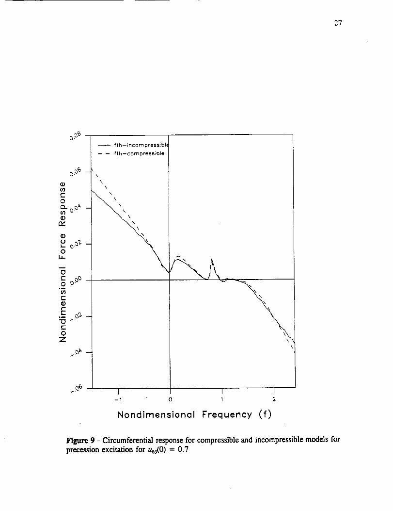
27
o=
o __
Eo_ a
ro
Z
i
fth-incompressible
--- fth-compressible
\\\
!
\
-1 0 1 2
Nondimensionol Frequency (f)
Figure 9 - Circumferential response for compressible and incompressible models for
precession excitation for U0o(O) = 0.7

28
show that the effects of compressibility do not affect the results of the model to a
great extent over the frequency range considered. As with Childs' results, local
resonance peaks occur in the response curves. Two local peaks occur in the response
curves, at nondimensional frequency ratios off = 0.1 and f = 0.8. For low inlet
values of circumferential velocity u_0) = 0.5, the behavior of the response curves
of the compressible model is virtually the same as the results shown for an
incompressible model shown by Childs (1989), i.e., the resonance in the response
curves diminish at lower values of inlet circumferential velocity.
Complex first-order pressure, path velocity, and circumferential velocity for
different nondimensional excitation frequencies along the leakage path produced from
the first-order perturbation analysis provide approximate complex modes at the
resonant frequencies. The real and imaginary parts of these results are used to obtain
amplitude and phase plots at the resonant frequencies. Amplitude and phase plots of
first-order nondimensional pressure in the leakage path at the frequency ratios off --
0.1 and f = 0.8, where the local peaks occur, are shown in Figures 10 and 11.
Complex modes for ua at the same frequency ratios are shown in Figures 12 and 13.
At the frequency ratio of f = 0.1, the amplitude of the pressure along the
leakage path steadily increases and has a maximum value at the exit of the leakage
path. For the frequency ratio off = 0.8, the maximum pressure amplitude occurs
near the middle of the leakage path. The mode shape for ua at f -- 0.1 shows a
slightly decreasing amplitude along the leakage path, with a minor increase in the
amplitude at the exit. As with the mode shape for the pressure distribution at f ---
0.8, the maximum magnitude occurs near the middle of the seal.
As with Childs' model, the resonant peaks found in this analysis can be
attributed to the centrifugal acceleration terms. When the centrifugal acceleration
terms are removed from the model, the local peaks in the response curves diminish
significantly. The mode shapes at f --- 0.8 do not support the theory that maximum
pressure oscillations at the leakage path exit are causing the seal to melt because the
maximum amplification occurs near the middle of the leakage path.

29
O
ID
E,q[
5O
so-J
"01
'° li
20 -4
10J
L'"
o _
0.0 o.1
Mode Shape
z
J
J
0.2 0.3 0.4 0.5 0.6 0.7 0.8 0.9
Nondimenmlonal Path Length (s)
,o
IgIf10
t-
O.
,8o/135 1
gO 41
45
0
-90
-135
-180
0.0
Phose Plot
w
, , : ' : , , , :0.1 0.2 C 3 0.4 0 5 0.6 0.7 0.8 0 9 1.0
Nondimensional Path Length (s)
tic.re lo - Amplitude and phase plot of nondimensional pressure p for precessional
excitation of compressible model at f = O. 1

30
60
50 J
1
© i
-s
_. 30
E 4,( i
2O -4
IC :
p. -0 ,
0.0
i
/
i
s
Mode Shape
i
o'.1 0.2 0.3 o'., 0:5 o'.6 0:7 0.8 0.9
Noncllmenslonal Path Length (s)
\ i
I
1.0
0
4=I&.
180
135
gO
45 -1..\
0
-90
-135
-180
0.0
Phase Plot
\
"\fI I I i
01.1 0._ 01.3 014 0.._ 0'._ 0.7 OI._ _,9
Nondlmenlional Path Length (s)
.0
Figure 11 - Amplitude and phase plot of nondimensional pressure p for precessional
excitation of compressible model at f = 0.8

31
Mode Shcpe
¢1
"10
mel.
E
=_,'
2
,i
3.2 0 3 04 0.5 0.5 _.,
Nondlmensional Path Length (s)
0.8 G.g
IgIn
0
4=n
Phase. Plot
180 ,
135J
igo -_
• 5 -'_ - -'- -
I-45 -4
-90 J
-135 4
i-_80 t
0.0
I ' I '
o., 0:2 o:3 o., 0:5 o., 0:7 o:, 0:9Nondimensional Path Length (s)
.0
Figure Z2 - Amplitude and phase plot for precessional excitation for path velocity u,z
of compressible model at f = O. 1
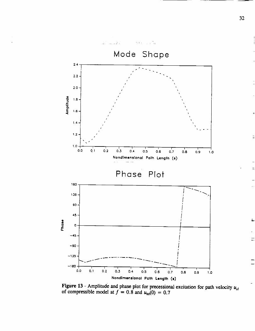
32
E
O
O
O.
=J
2.4
2.2
2.0
1.8
1.6
14
1
0.0
Mode Shape
J
i
I
/
/ x
i x
/
O. 1 0 2 0.3 0 4 0,5 0 6 0.7 0.8 0-9 1.0
Nondlmenslonal Path Length (s)
Phase Plot
180
13.5
90
45-
0
--45
-90
-135
-180
0.0
P
f
/iI
/I
/if
Ii/.f
i I i I I I I I t0 I 0.2 0 3 0.4 0.5 0.6 0.7 0.8 0.9 .0
Nondlmenslonal Path Length (s)
Figure 13 - Amplitude and phase plot for precessional excitation for path velocity u,zof compressible model at f = 0.8 and uoo(0) = 0.7

33
Noticeableeffectsof compressibility upon the model can be seenat higher
nondimensionalfrequency ratios. Figure 14 shows the responsecurves of the
compressibleand incompressiblemodels for high frequency ratios. The force
responsesof the incompressiblemodelcontinueto grow with increasingf, while the
results of the compressible model exhibit peaks corresponding to the natural
frequency. This is consistent with classical vibration analysis, with the incompressible
model having no natural frequency due to an infinitely high bulk modulus, while the
compressible model has a natural frequency corresponding to the compressibility of
liquid hydrogen in the model.
6.2 Pressure Excitation
This part of the research involves introducing a time and circumferentially
varying impeller discharge pressure to the compressible model. With different
excitations involved in this model, new boundary conditions also exist. The pressure
perturbation takes the form of the following equation.
• Supply Pressure-Excitation Perturbation
e,(0,t)= (45)
The occurrence of epsilon in this equation represents the perturbation coefficient for
discharge-pressure excitation.
6.2.1 First-Order Equations
Nondimensionalization and perturbation of the general governing equations (6-
8) yields the same governing equations for pressure excitation perturbation as for
precession excitation governing Eqs. (31-33), except with ht = 0 for this model.
Therefore, the first-order governing equations for pressure excitation will not be
presented in this section.

34
,,I,--
¢-(D
,m
O
,,¢--
(DO
CD
(D(Dk_O
La_
2 -
I --
0 -
0
fr-incornpressible
fib--incompressible I
fr-cornpress;bte
fib-compressible /
= --_-- ....... 1
t
, 1, 1, 1, i
t
t
| i
t t
l i
t i
t f
I I
I I I I I 12 4 6 8 10
Nondimensionol Frequency (f)
12
Figure 14 - Nondimensional force response of compressible and incompressible models
for precessional excitation for extended frequency range

35
6.2.2 Boundary_ Conditions
Nondimensionalization and perturbation of the boundary conditions introduced
in Eq. (12-13), the first-order boundary condition can be stated as
ps_(O,t)-pl(0,0,t) =(1+ _)u,,(0,0,tll +(1+_)dO 10]2 dp (46)
p_(1,e,t)-p,,(o,t) =Cdeuso(1)us_(1,O,t(l + (1+2_) dOdpI,)
p,l(O,O, p,1(O,O provide the boundary excitations and take the form,
p,_lo.t)=d°%:osno +p,_:innO)p,j(o.o =eJ_'_,_ccosnO+p,_r_nnO)
(47)
6.2.3 First Order Solution
The them and time dependency of the first-order pressure excitation governing
equations is eliminated by assuming
u,_=e_ (u,_cosnO+u,_:innO)
uol=ed#(UOlcCOsnO+ltsl:irtnO)
Pl =ca' (P_c°s nO+pusin nO)
(48)
where n represents the difference of number of impeller blades and vanes, also defined
as the number of diametral nodes (Bolleter). Substitution of Eqs. (48) into the first-
order pressure excitation governing equations, equating coefficients of cos nO and sin
nO, and using complex variables described in Eq. (30) reduces the real equations to
three, complex ordinary differential equations
I P,J I P,J
=0 (49)

36
where
Bll
Ax, A2o +JTT A dP° bL,
A4s B33 dPoB3_ B32 .....
P0 00 ds
(50)
Eq. (49) differs from Eq. (40) in that Eq. (49) is now a function of n with h t - O.
These equations are solved using the method presented by Childs (1992).
6.2.4 First-Order Results
Results from the pressure excitation perturbation analysis using a difference of
impeller blades and vanes (n) is presented in this section. Since the SSME HPFTP
wearing-ring seal is located at the end of the leakage path (s = 1), the results from
this section will concentrate on this area of the leakage path. The pressure-oscillation
response at the end of the leakage path versus nondimensional excitation frequency
corresponding for n = 11 is illustrated in Figure 15. The value of n = 11 is used
because, as mentioned previously, the SSME HPFTP has 24 impeller blades and 13
diffuser vanes, for a difference of 11. Bolleter (1988) explains that the dominant
pressure pattern to be expected for this arrangement would have 11 diametral nodes.
This is important because it is the value used as n in Eq. (48). Figure 15 shows that
the peak pressure oscillation at the exit of the impeller leakage path (s = 1) occurs at
a nondimensional frequency of about f = 6.4 and f 7.8. Bolleter predicts that the
peak pressure oscillation should occur as a function of the difference in the number
of impeller blades and vanes, presented in Tables 1 and 2.

3"1
20.0
G)
.m
E.f
Q_
17.5 --
15.0 --
12.5 --
10.0 --
7.,_
5.0
2.5
0.0
0
J
I I t2 4 6 8 10
NondimensionQ! Frequency (f)
12
Figure 15 - Pressure oscillation response of compressible model for pressure
excitation for n - 11 at leakage path exit (s ffi 1) and _(0) - 0.7

38
The resonant frequency ratios at f = 6.5 and f = 7.8 clearly are not functions
near the predicted excitation frequencies provided in Table 2 for n = 11. None of the
other cases tested yielded results which correspond to the values shown in Table 2 for
the respective value of n. These results reveal that amplification of peak pressure
oscillation does not occur at the expected frequency ratio. At the predicted frequency
ratios, the cases tested for this model showed that an attenuation, rather than an
amplification of the pressure waves occurred.
Table 1 - (nz - n,_) for various combinations of multiples of impeller blades and vanes
13
26
39
n I 24 48 96
11 35 83
-2 22 70
-15 9 57
Table 2 - Expected peak nondimensional frequency ratios, f or, {n/(n t -
various combinations of multiples of impeller blades and vanes
nl 24 48 96n,
\13
26
39
2.18 1.37 1.16
-12.00 2.18 1.37
-1.60 5.33 1.68
ng}, for
Amplitude and phase plots (Figures 16 and 17) of the pressure oscillation for
the two resonant frequency ratios found for n for the compressible pressure excitation
model show that the peak pressure oscillation occurs at the exit of the leakage path.
This result helps to support the hypothesis that pressure oscillations at the leakage path

39
G
4-ww
E,¢
2.5
2.0
!.5
!.0 --
0,5
0.0
0.0
\
Mode Shape
I
i
I \
/ \/
/ \/ \
/ !
I ; : 1 ) i0 3 0.4 0.5 0.6 0.7 03 0.9
Nondlmenslonal Path Length (s)
) i
o.1 0.2 1.0
@
i-n
Phase Plot
180
135 -
go
45
0
-45
-90
-135 -
-180
0.0
II
/
i
ii
i
!
i
I
II
!
i
0.1 0 2 0.3 0.4. 0 5 0.0 0.7 0 8 0 9 1.0
Nondlmenslonal Path Length (s)
Figure !6 - Amplitude and phase plot for pressure oscillation of compressible model
inside impeller leakage path at f = 6.4 for n - 11 and u_0) 0.7

4O
@
"E
__=o.E
.<
10 ,
II
E!
64
I
o_0.0
Mode Shape
/
/
/
/
0.1 0.2 0.3 04 0.5 0.6 0.7 018 0.9
Nondlmensional Path Length (s)
i
!
/
/
:.0
@ela
f
18Ot
135 1
gO
45
0
-gO
-135 i-180
0.0
Phase Plot
i "
i
t
i
z
i
/
/
/
/
/
I
I
/
I I _, t I
0.1 0.2 _.3 0'.4 0.5 0.6 017 OI._ O_.g
Nondimensional Path Length ($)
z
/
/
.0
Figure 17 - Amplitude and phase plot for pressure oscillation of compressible model
inside impeller leakage path at f = 7.5 for. = 11 and u0(0) = 0.7

41
exit are causing the seal to melt. However, the result does not provide enough
evidence to provide a very plausible explanation for the behavior exhibited by the
wearing ring seal.
The response of the compressible model for other values of n is plotted in
Figure 18. The graph shows the relationship of the peak pressure oscillation response
to the number of diametral nodes. The nondimensional excitation frequency ratio at
which the peak pressure oscillation occurs increases as the number of diametral nodes
increase, consistent with Childs' analysis (1992). However, unlike Childs' results,
where the magnitude of the peak amplitude stays relatively constant, regardless of n,
the results produced from the compressible model show that the amplitude of the
pressure oscillations increases as n increases. The effects of added compressibility to
the results of this model is greatly enhanced compared to results of the precession
excitation model. But, as with the precession excitation analysis, the influence due to
compressibility effects is only noticeable at higher nondimensional frequencies.

42
g_
E
(3.
20.0
15.0 --
2.5 l_ \
o.o 10 2 4 6 8 10 12
Nondimensional Frequency (f)
Figur_ i8 - Pressure o_illation re_nse for pressure oscillation of compressiblemodel with multiple n and u_O) - 0.7

43
CHAPTER VH
FIRST ORDER EQUATIONS AND SOLUTIONS FOR ACOUSTIC MODELS
For acoustics analysis, the temporal acceleration terms are the only acceleration
terms which remain from the set of general governing equations. A highly reasonable
assumption may be made that the contributions from the convective, Coriolis, and
centrifugal acceleration terms are negligible compared to the temporal acceleration
terms in the realm of ordinary acoustics (M _ ,, 1) (Thompson, 1988). However, due
to the high Mach number with which the working fluid in the SSME HPFTP operates
(M _-- 0.4), the general perturbation fluid model and the acoustic model must be
compared to investigate the effects of the convective, Coriolis, and centrifugal
acceleration terms in an acoustic analysis.
The zeroth-order solution for the acoustics models do not change from the
previous results obtained because the zeroth-order equations and solution remain the
same.
7.1 Precession Excitation Model
7.1.1 First Order E_.uations
First-order governing equations for the acoustic precession excitation model can
be obtained by removing the effects of fluid mechanics, i.e., the convective, the
Coriolis, and the centrifugal acceleration terms from the general perturbation governing
equations given in 5.2.2, Eqs. (24-26). Removing the convective acceleration terms,
uoduo/ds uAu,/ds, the Coriolis acceleration term, 2uAlr/rds, and -2uoodr/(b:rds),
representing centrifugal acceleration, from the continuity Eq. (24) yields the first-order
governing acoustic continuity governing Eq. (51). The first-order governing acoustic
equations for the path and circumferential momentum are obtained by removing the
convective acceleration terms from F.qs. (25-26).

44
• Continuity Equation
0oo_ +h hio a_ as=0 (51)
• Path-Momentum Equation
1 op,
Po asm__ +ueIAzf+us_A:_+ OzA4_+ T_---._--=htA _
• Circumferential-Momentum Equation
+ uorA2e + uff430 + (JIA4o +T_o_ =htale
(52)
(53)
7.1.2 First-Order Precession Excitation Solution
The theta dependency of Eqs. (51-53) can be eliminated by substituting the
solution format presented in Eq. (29). The three resulting complex equations in the
independent variables s and r after introducing the complex variables of Eq. (32) are
• Continuity Equation
i_sl jeT [1 0h0+ 1 0P0] [UsoOho ._Too 1(54)
• Path-Momentum Equation
/
_oC_(55)

45
• Circumferential-Momentum Equation
b L, Oq + + __tA4e + Tcz_ -r R i Po +ttelA2° us:3e
0_1 - h_o (56)
Assuming the harmonic seal motion described in section 6.1, Eq. (38), the three
governing equations reduce to two differential equations of motion of the form,
(57)
where
us°dP°G +F +.rTdz ._T Ale
(58)
The [C] matrix elements are given in Appendix C.
The dues/ds term has dropped from the governing equations and thus uei can
be solved directly without integrating the partial differential equations, yielding,
u0,.l,:,0(59)
Results to these equations are obtained using the same solution procedure and
boundary conditions described for the first-order precession excitation equations in
section 6.2.2. The solution to these sets of equations can then be used to calculate the
force and moment coefficients in the impeller leakage path for the acoustic ease where
classical acoustic assumptions are made.

46
7.1.3 First-Order Results
The nondimensional radial force coefficient responses for the general
perturbation and acoustic cases are shown in Figure 19. The response curves for the
circumferential force coefficients are shown in Figure 20. The response curves for
the acoustic case are less erratic in behavior, and the peaks exhibited by the
compressible model totally disappear. This shows that the convective, Coriolis, and
centrifugal acceleration terms do affect the results of the compressible model to a
considerable extent at low frequencies. Childs (1989) correctly predicted that the
centrifugal acceleration terms caused the resonance in the response curve. Although
the results of the two models do not differ quantitatively, the trend exhibited by both
models are similar, as evidenced by Figures 20 and 21.
At higher values of nondimensional frequency, the effects of removing the fluid
mechanics terms from the model is shown in Figure (21). The two models show
about the same results. The natural frequency of the acoustic model is slightly lower
and the peaks are slightly higher. Mode shapes for pressure oscillations at f = 11.5
and f = 12 are shown in Figures 22 and 23. The mode shapes show that, at these
frequencies, the pressure oscillations are not the cause of the uncharacteristic behavior
of the exit wearing ring seal due to a precession excitation. The mode shapes do not
show conclusively that the pressure oscillations are occurring at the exit of the seal.
7.2 Pressure Excitation Model
7.2.1 First-Order Equations
The equations obtained for the first-order acoustic pressure excitation
perturbation use the same procedure as for the first-order acoustic precession
excitation shown in section 7.1.1. The boundary conditions and perturbation
excitation are defined by the equations used for the general first-order pressure
excitation solution given in section 6.2. The resulting governing equations for
pressure excitation of the acoustic model are the same as those given in section 7.1. I,
except with h t being zero, analogous with the results obtained for the pressure
excitation equations for the general perturbation model.

4?
Q3(/1
EO
_)CE
Q)
Oi,
w
E)
E
EO
Z
\,
__ . fr--compress[bl e
-- - fr--ocoust{c
\',
\',
\
\,I
\,I
\,J
I
f
//
/
//
/
/,"/
I I
I I
I/ _ J
//,/,,
/,/,
I
/,i
/,I
/ ,I
I
I
t
I
I
I
I
I
I
I
I
I
i z
] I
//
/
-1 0 1 2
Nondimensional Frequency (f)
Figure 19 - Radial response for acoustic and compressible models for precessionalexcitation for u_0) = 0.7

48
(D03
0"}
n,-
_DL_k-
OLa_
m
c-O
J_
cn Oq._¢- .,-.
Eem
Oz
--- f_._--compressible
.... ft,_--acoustic
, \
t_
• \,/ "\ _," \j
. \
"'",,,,,. '\,\
l I-1 0 1 2
Nondimensional Frequency (f)
Figure 20 - Circumferential force response for acoustic and compressible models for
precessional excitation for u_0) = 0.7
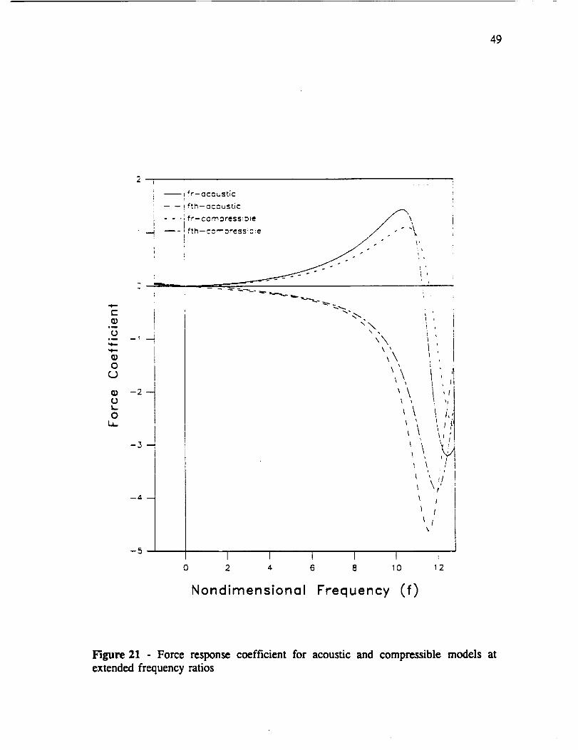
49
(-(D
iI
(3J_
(DOcJ
(D(3k.OL_-
-2--
-4.--
-5
--Lfr--oCO_StiC
-- -- Ift_--CCOuStic
- - .ifr-ccmoressioze _ _\
--4 _-!fth--cc--_ress!:_e / -" "_
q\\ •
\\\ ,
\\\
,\
i '
i
_ p
1
i
q
i
! , f
_. \ i i• i
_I l
I I I I I :0 2 4 6 8 10 _2
Nondimensional Frequency (f)
Figure 21 Force response coefficient for acoustic and compressible models atextended frequency ratios

5O
O
10-1
o_
E
25000
20000
15000
10000
5000
0
0.0
/
/
I
i
i
I
0.1
Mode Shape
/
/
z
z
/
J
/
/
t
i
i
i x
/x
x
x
x
\
x
o12 o13 oi, 0:5 o18 o17 o18 o19Nondimenslonal Path Length (s)
%
1.0
Phase Plof
180
q;
0
Q.
135
90
4.5
0
-4.5
-90
-135 -
-180
0.0
.,_
1
/\
011 01.2 OL3 014" 0'.5 0'.8 017 0:8 019 1.0
Nondimen=ional Path Length (s)
Figure 22 - Amplitude and phase plot of nondimensional pressure of acoustic model
vs. path length at f = 11.5 for u_0) = 0.7
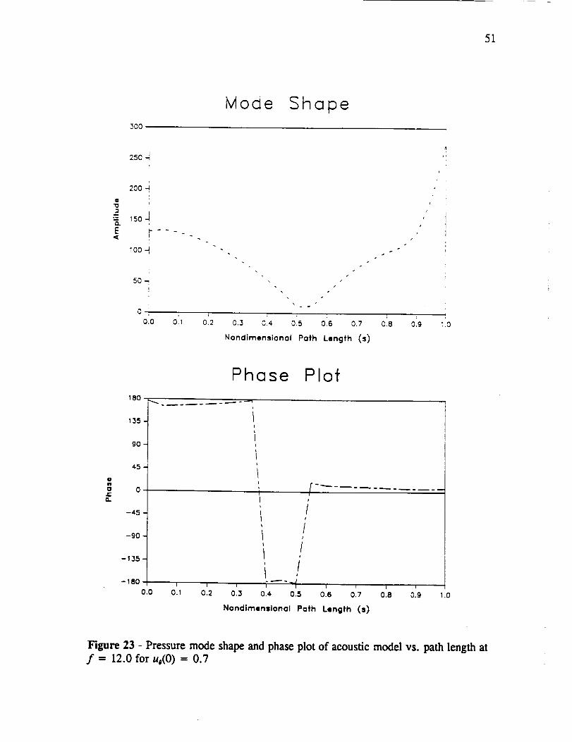
51
_00
Mode Shape
O
°wn
E
250 J
200 J
i
150 -J
PI
loo -_
5o_
oolo oi,
F
o:2 0.3 o:, 05 o:6 o.7 o'.a
Nondimensional Path Length (s)
s
J
i
0.9 :.0
,IgIf'l
0
z"rt
Phase Plot
180 ,,_,
135 1
'°14.5
0
-,t.5
-90
-135
-180 I
i IC2 0.30.0 0.1
///i
Ii
O.4 0.5 0.6 0.7 0.8 0.9
Nondlmenslonal Path Length (s)
1.0
Figure 23 - Pressure mode shape and phase plot of acoustic model vs. path length atf = 12.0 for uo(O) = 0.7

52
0.5
0.4
_D
0.1
I
I
I
II
11
I!
|I
i
I I
I
t
I
t
I
t
I
I
I
!
t
t
%
o.o I i ..... I'''---1- I I I0 2 4 6 8 10 12
i
Nondimensional Frequency (f)
Figure 24 - Acoustic response for impeller discharge pressure excitation for n ffi 11
for u,o(O) = 0.7

53
7.2.2 First-Order Pressure Excitation Solution
Using F-xl. (48) to eliminate the theta and time dependency from the first-order
pressure excitation of the acoustic model and using the pressure excitation perturbation
described in Eq. (45), the resulting governing equations can be represented as,
=0(60)
Where elements of [D] are provided in Appendix D.
In addition to hi being zero, Eq. (60) also is a function of n, unlike Eq. (57).
7.2.3 First-Order Results
Comparison of the general perturbation model and the acoustic model for n = 11
shows that the peak pressure amplification around f = 7.8 displayed by the general
perturbation model almost totally disappears for the acoustics model. From Figure 24,
the results for the acoustics model show that no amplification of the pressure
oscillation occurs, but rather, an attenuation of the pressure oscillation at all frequency
ratios. It can be concluded from this result that the convective, Coriolis, and
centrifugal acceleration terms contribute significantly to the results of a bulk flow
model when a pressure excitation is used as the perturbation parameter of the bulk
flow model. The results here also differ with respect to the location of the resonant
peaks in the nondimensional frequency range tested. For the acoustic model, the local
peaks do not match with those of the compressible model.
The sharp peak of the pressure amplitude near a frequency ratio of f = 0.0 is
inherent in all the models (compressible, incompressible, and acoustic), shown in
Figure 25. The phenomenon causing this resonant excitation is not yet understood and
cannot be explained. However, the fact that this resonance occurs in all three models
explains that neither the compressibility or the acoustics effects of the models affects
this resonant frequency. Also, the fact that the frequency at which resonance occurs
is near f = 0.0, indicates that this peak could be the response to a free vibration of
54
the fluid inside the leakage path.
Figure 26 shows the first-order pressure response for multiple cases of n. The
frequency responses due to different n show no quantitative trend with respect to n.
Unlike the compressible model, where the pressure response showed a definite,
noticeable response to different n, the acoustic model shows little quantitative and
qualitative response to different n value.

55
2.5
2._
- l- acoustic
---e-. compressible
---e- incompressible
_)
-_ 1.5-4--
<
0.5
0.0
Nondimensional Frequency (f)
Figure 25 - Pressure response of incompressible, compressible, and acoustic modelfor impeller discharge pressure excitation for a = 1 for ueo(0) = 0.7

56
o2 L_
\01
.I
o o t I I0 2 4 6 8 10 12
NondTmensionol Frequency (f)
Figure 26 - Pressure response for pressure excitation for multiple n

57
CHAPTER VIII
SU_IARY AND CONCLUSIONS
A modified approach to Childs' previous work (1989,1992) on fluid-structure
interaction forces in the leakage path between an impeller shroud and its housing is
presented in this thesis. Three governing equations consisting of a continuity, path-
momentum, and circumferential-momentum equations were developed to describe the
leakage path inside a pump impeller. Radial displacement perturbations were used to
solve for radial and circumferential force coefficients. In addition, impeller-discharge
pressure disturbances were used to obtain pressure oscillation responses due to
precessing impeller pressure wave pattern. Childs' model was modified from an
incompressible model to a compressible barotropic-fluid model (the density of the
working fluid is a function of the pressure and a constant temperature only). Results
obtained from this model yielded interaction forces for radial and circumferential force
coefficients. Radial and circumferential forces define reaction forces within the
impeller leakage path.
An acoustic model for the same leakage path was also developed. The
convective, Coriolis, and centrifugal acceleration terms are removed from the
compressible model to obtain the acoustics model. The compressible model is
compared with the incompressible model and the acoustic model. A solution due to
impeller discharge pressure disturbances model was also developed for the
compressible and acoustic models. The results from these modifications are used to
determine what effects additional perturbation terms in the compressible model have
on the acoustic model.
The results show that the additional fluid mechanics terms in the compressible
model do cause resonances (peaks) in the force coefficient response curves. However,
these peaks only occurred at high values of inlet circumferential velocity ratios. The
peak pressure oscillation was shown to occur at the wearing ring seal. Introduction of
impeller discharge disturbances with n diametral nodes showed that maximum peak

58
pressureoscillationsoccurredat nondimensionalexcitationfrequenciesoff = 6.4 and
f = 7.8 for this particular pump. Bolleter's results suggest that for peak pressure
oscillations to occur at the wearing ring seal, the nondimensional excitation frequency
should be on the order of f = 2.182 for n = 11. The resonances found in this
research do not match those predicted by Bolleter. At the predicted frequencies given
by Bolleter, the compressible model shows an attenuation of the pressure oscillations
at the seal exit. This does not provide a plausible explanation for the unusual behavior
exhibited by the wearing ring seal.
The compressibility of the fluid does not have a significant influence on the
model at low values of nondimensional frequency. At high values of nondimensional
frequency, the effects of compressibility become more significant. For the acoustic
analysis, the convective, Coriolis, and centrifugal acceleration terms do affect the
results to a limited extent for a precession excitation and a large extent for a pressure
excitation when the fluid operates at relatively high roach numbers.

59
REFERENCES
Bolleter, U., 1988, "Blade Passage Tones of Centrifugal Pumps", Vibrations,
Vol. 4, September, pp. 8-13.
Childs, D. W., 1989, "Fluid-Structure Interaction Forces at Pump-Impeller-
Shroud Surface for Rotordynamic Calculations," ASME Journal of Vibrations,
Acoustics, Stress, and Reliability in Design, Vol. 111, July, pp. 216-225.
Childs, D. W., 1992, "Pressure Oscillations in the Leakage Annulus Between
a Shrouded Impeller and Its Housing Due to Impeller-Discharge-Pressure
Disturbances," Journal of Fluids Engineering, Vol. 114, March, pp. 61-67.
McCarthy, R. D., 1986, "Thermophysical Properties of Fluids, MIPROPS 86,"
NBS Standard Reference Data Base 12, Thermophysies Division, Center for Chemical
Engineering, National Bureau of Standards, Boulder, Colorado.
Morrison, G. L., Rhode, D. L., Logan, K. C., Chi, D., Demco, J., 1983,
"Labyrinth Seals for Incompressible Flow - Final Report," G. C. Marshall Space
Flight Center, MSFC, Alabama, 35812, Report Number SEAL-4-83, November.
San Andres, L., 1991, "Analysis of Turbulent Hydrostatic Bearings with a
Barotropic Fluid, _ Transactions of the ASME, ASME Journal of Tribology, pp. 1-10.
Thompson, P. A., Compressible Fluid Mechanics, Department of Mechanical
Engineering, Rensselaer Polytechnic Institute, Troy, New York, 1988, pp. 159-163.
Thomson, W. T., Laplace Transformations, Prentice Hall, Inc., Englewood
Cliffs, New Jersey, 1960, Second Edition, pp.181-201.
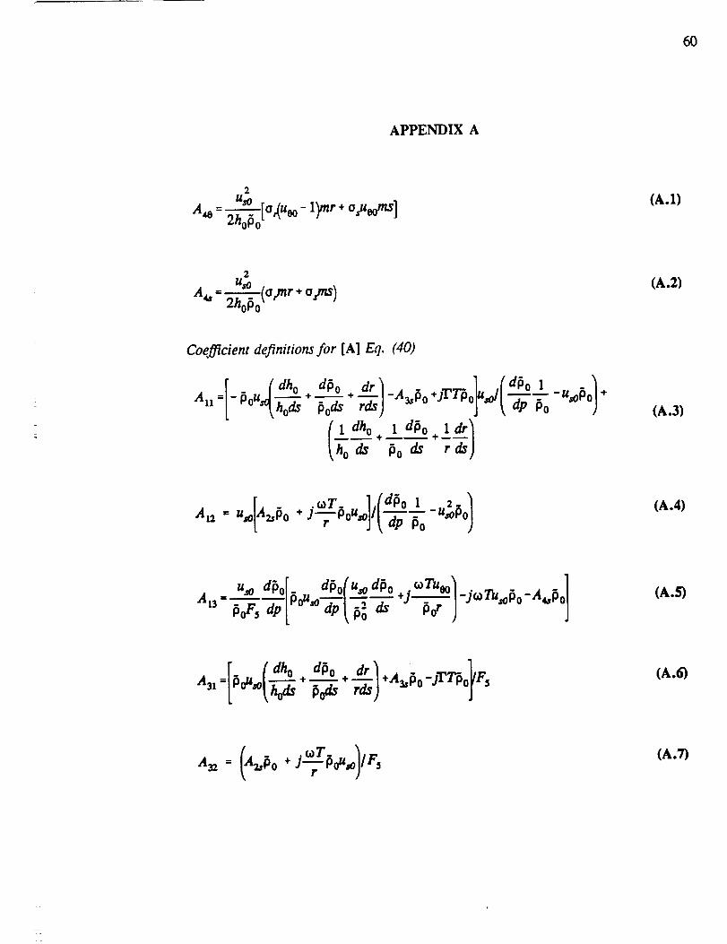
6O
APPENDIX A
2
- us° l_nr a_eomS](A.1)
A_- _ (attar + o.jns)2hoPo_
(A.2)
Coefficient definitions for [A] Eq. (40)
( dho dPo dr +jT'Tp sol 1a.= -_o,,_h--_÷_o--_+_ -A_,_o _o1 dho + 1 dPo l dr I
(A.3)
[A caT ](dfio 1 _u_fio/a,2= U_o z,_o +JT_oU,o]l '_- _o(A.4)
U_o dPo[. dPo(%odPo .¢aT%o_
a_.o_,.[oo_t,_ _ .-_-] -j=ru_ofi o-Ae_c (A.5)
)-_ods rds
(A.6)
(A.7)
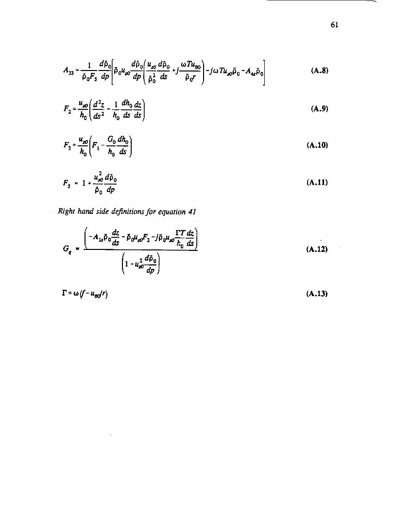
61
_ a_o[.u d_o(U,oa_o_rUoo_ _a,,_o](A.8)
Uso( d2z 1 dho _)(A.9)
U,O(F_ Oodho1F3=_ ho(A.10)
2
uso dP o
_o dp(A.11)
Right hand side definitions for equation 41
dz .. rraz_-A_P°_ - P°ua'F2-JP°u'°-';---"ods)Gq=
1 2 dPo /
(A.12)
r=_o(f-udr ) (A.13)

62
APPENDIX B
Coefficient definitions for [B] of Eq. (50)
(B.I)
.nuT. dPo 1 -u_oPoB_2= U,o z#o * J--f-'Pou /"_ _o
(B .2)
B13 =
u_ d_o[" dOo(%odOo +j n 6°Tu°° I -jn coTU_o_o - A _ _
](B.3)
[. u( dho + dJ_&°+___)+aas_o-jI'T_ol/F5B31 =[0° _h-_ _ods
(13.4)
B_ = (AzsPo + J-_PoU_)/ F5(B.5)
_ 1 dOo[. dPo{u,odPo nt°Tuoo i -jnco T%o_ o -A_ o (B.6)

63
APPENDIX C
Coefficient definitions for [C] of Eq. (57)
= [1 dh 1 dgo÷A3e_2T_+j_42eA30_] (c.1)
C:, : Au-Aec
(C.2)
Cl2 = A_ [ r2Rj_o ap ] rRi[3 0 bo 2 d$
(C.3)
(C.4)

64
APPENDIX D
Coefficient definitions for [D] of Eq. (60)
rAoc rAec J
(D.1)
A oa e4 D2t = Ax,
Aoc
(D .2)
"A2ebLs ÷f_._pA,el+_FTd'o 1 (A " d'° fn2_2TibLsll(D.3)
(D.4)
2 +n2¢a2T2f2Aec =A2o(D.b3