PART 8. TRAFFIC CONTROL FOR RAILROAD AND LIGHT RAIL TRANSIT GRADE...
46
2009 MUTCD Text Part 8 - Page 1 of 46 December 2009 PART 8. TRAFFIC CONTROL FOR RAILROAD AND LIGHT RAIL TRANSIT GRADE CROSSINGS CHAPTER 8A. GENERAL Section 8A.01 Introduction Section 8A.02 Use of Standard Devices, Systems, and Practices at Highway-Rail Grade Crossings Section 8A.03 Use of Standard Devices, Systems, and Practices at Highway-LRT Grade Crossings Section 8A.04 Uniform Provisions Section 8A.05 Grade Crossing Elimination Section 8A.06 Illumination at Grade Crossings Section 8A.07 Quiet Zone Treatments at Highway-Rail Grade Crossings Section 8A.08 Temporary Traffic Control Zones CHAPTER 8B. SIGNS AND MARKINGS Section 8B.01 Purpose Section 8B.02 Sizes of Grade Crossing Signs Section 8B.03 Grade Crossing (Crossbuck) Sign (R15-1) and Number of Tracks Plaque (R15-2P) at Active and Passive Grade Crossings Section 8B.04 Crossbuck Assemblies with YIELD or STOP Signs at Passive Grade Crossings Section 8B.05 Use of STOP (R1-1) or YIELD (R1-2) Signs without Crossbuck Signs at Highway-LRT Grade Crossings Section 8B.06 Grade Crossing Advance Warning Signs (W10 Series) Section 8B.07 EXEMPT Grade Crossing Plaques (R15-3P, W10-1aP) Section 8B.08 Turn Restrictions During Preemption Section 8B.09 DO NOT STOP ON TRACKS Sign (R8-8) Section 8B.10 TRACKS OUT OF SERVICE Sign (R8-9) Section 8B.11 STOP HERE WHEN FLASHING Signs (R8-10, R8-10a) Section 8B.12 STOP HERE ON RED Signs (R10-6, R10-6a) Section 8B.13 Light Rail Transit Only Lane Signs (R15-4 Series) Section 8B.14 Do Not Pass Light Rail Transit Signs (R15-5, R15-5a) Section 8B.15 No Motor Vehicles On Tracks Signs (R15-6, R15-6a) Section 8B.16 Divided Highway with Light Rail Transit Crossing Signs (R15-7 Series) Section 8B.17 LOOK Sign (R15-8) Section 8B.18 Emergency Notification Sign (I-13) Section 8B.19 Light Rail Transit Approaching-Activated Blank-Out Warning Sign (W10-7) Section 8B.20 TRAINS MAY EXCEED 80 MPH Sign (W10-8) Section 8B.21 NO TRAIN HORN Sign or Plaque (W10-9, W10-9P) Section 8B.22 NO GATES OR LIGHTS Plaque (W10-13P) Section 8B.23 Low Ground Clearance Grade Crossing Sign (W10-5) Section 8B.24 Storage Space Signs (W10-11, W10-11a, W10-11b) Section 8B.25 Skewed Crossing Sign (W10-12) Section 8B.26 Light Rail Transit Station Sign (I-12) Section 8B.27 Pavement Markings Section 8B.28 Stop and Yield Lines Section 8B.29 Dynamic Envelope Markings CHAPTER 8C. FLASHING-LIGHT SIGNALS, GATES, AND TRAFFIC CONTROL SIGNALS Section 8C.01 Introduction Section 8C.02 Flashing-Light Signals Section 8C.03 Flashing-Light Signals at Highway-LRT Grade Crossings Section 8C.04 Automatic Gates Section 8C.05 Use of Automatic Gates at LRT Grade Crossings Section 8C.06 Four-Quadrant Gate Systems Section 8C.07 Wayside Horn Systems Section 8C.08 Rail Traffic Detection
Transcript of PART 8. TRAFFIC CONTROL FOR RAILROAD AND LIGHT RAIL TRANSIT GRADE...
2009 MUTCD Text Part 8 - Page 1 of 46 December 2009
PART 8. TRAFFIC CONTROL FOR RAILROAD AND LIGHT RAIL TRANSIT GRADE CROSSINGS
CHAPTER 8A. GENERAL Section 8A.01 Introduction Section 8A.02 Use of Standard Devices, Systems, and Practices at Highway-Rail Grade Crossings Section 8A.03 Use of Standard Devices, Systems, and Practices at Highway-LRT Grade Crossings Section 8A.04 Uniform Provisions Section 8A.05 Grade Crossing Elimination Section 8A.06 Illumination at Grade Crossings Section 8A.07 Quiet Zone Treatments at Highway-Rail Grade Crossings Section 8A.08 Temporary Traffic Control Zones
CHAPTER 8B. SIGNS AND MARKINGS Section 8B.01 Purpose Section 8B.02 Sizes of Grade Crossing Signs Section 8B.03 Grade Crossing (Crossbuck) Sign (R15-1) and Number of Tracks Plaque (R15-2P) at Active
and Passive Grade Crossings Section 8B.04 Crossbuck Assemblies with YIELD or STOP Signs at Passive Grade Crossings Section 8B.05 Use of STOP (R1-1) or YIELD (R1-2) Signs without Crossbuck Signs at Highway-LRT Grade
Crossings Section 8B.06 Grade Crossing Advance Warning Signs (W10 Series) Section 8B.07 EXEMPT Grade Crossing Plaques (R15-3P, W10-1aP) Section 8B.08 Turn Restrictions During Preemption Section 8B.09 DO NOT STOP ON TRACKS Sign (R8-8) Section 8B.10 TRACKS OUT OF SERVICE Sign (R8-9) Section 8B.11 STOP HERE WHEN FLASHING Signs (R8-10, R8-10a) Section 8B.12 STOP HERE ON RED Signs (R10-6, R10-6a) Section 8B.13 Light Rail Transit Only Lane Signs (R15-4 Series) Section 8B.14 Do Not Pass Light Rail Transit Signs (R15-5, R15-5a) Section 8B.15 No Motor Vehicles On Tracks Signs (R15-6, R15-6a) Section 8B.16 Divided Highway with Light Rail Transit Crossing Signs (R15-7 Series) Section 8B.17 LOOK Sign (R15-8) Section 8B.18 Emergency Notification Sign (I-13) Section 8B.19 Light Rail Transit Approaching-Activated Blank-Out Warning Sign (W10-7) Section 8B.20 TRAINS MAY EXCEED 80 MPH Sign (W10-8) Section 8B.21 NO TRAIN HORN Sign or Plaque (W10-9, W10-9P) Section 8B.22 NO GATES OR LIGHTS Plaque (W10-13P) Section 8B.23 Low Ground Clearance Grade Crossing Sign (W10-5) Section 8B.24 Storage Space Signs (W10-11, W10-11a, W10-11b) Section 8B.25 Skewed Crossing Sign (W10-12) Section 8B.26 Light Rail Transit Station Sign (I-12) Section 8B.27 Pavement Markings Section 8B.28 Stop and Yield Lines Section 8B.29 Dynamic Envelope Markings
CHAPTER 8C. FLASHING-LIGHT SIGNALS, GATES, AND TRAFFIC CONTROL SIGNALS Section 8C.01 Introduction Section 8C.02 Flashing-Light Signals Section 8C.03 Flashing-Light Signals at Highway-LRT Grade Crossings Section 8C.04 Automatic Gates Section 8C.05 Use of Automatic Gates at LRT Grade Crossings Section 8C.06 Four-Quadrant Gate Systems Section 8C.07 Wayside Horn Systems Section 8C.08 Rail Traffic Detection
2009 MUTCD Text Part 8 - Page 2 of 46 December 2009
Section 8C.09 Traffic Control Signals at or Near Highway-Rail Grade Crossings Section 8C.10 Traffic Control Signals at or Near Highway-LRT Grade Crossings Section 8C.11 Use of Traffic Control Signals for Control of LRT Vehicles at Grade Crossings Section 8C.12 Grade Crossings Within or In Close Proximity to Circular Intersections Section 8C.13 Pedestrian and Bicycle Signals and Crossings at LRT Grade Crossings
CHAPTER 8D. PATHWAY GRADE CROSSINGS Section 8D.01 Purpose Section 8D.02 Use of Standard Devices, Systems, and Practices Section 8D.03 Pathway Grade Crossing Signs and Markings Section 8D.04 Stop Lines, Edge Lines, and Detectable Warnings Section 8D.05 Passive Devices for Pathway Grade Crossings Section 8D.06 Active Traffic Control Systems for Pathway Grade Crossings

2009 MUTCD Text Part 8 - Page 3 of 46 December 2009
CHAPTER 8A. GENERAL Section 8A.01 Introduction Support:
1 Whenever the acronym “LRT” is used in Part 8, it refers to “light rail transit.” 2 Part 8 describes the traffic control devices that are used at highway-rail and highway-LRT grade crossings. Unless
otherwise provided in the text or on a figure or table, the provisions of Part 8 are applicable to both highway-rail and highway-LRT grade crossings. When the phrase “grade crossing” is used by itself without the prefix “highway-rail” or “highway-LRT,” it refers to both highway-rail and highway-LRT grade crossings.
3 Traffic control for grade crossings includes all signs, signals, markings, other warning devices, and their supports along highways approaching and at grade crossings. The function of this traffic control is to promote safety and provide effective operation of rail and/or LRT and highway traffic at grade crossings.
4 For purposes of design, installation, operation, and maintenance of traffic control devices at grade crossings, it is recognized that the crossing of the highway and rail tracks is situated on a right-of-way available for the joint use of both highway traffic and railroad or LRT traffic.
5 The highway agency or authority with jurisdiction and the regulatory agency with statutory authority, if applicable, jointly determine the need and selection of devices at a grade crossing.
6 In Part 8, the combination of devices selected or installed at a specific grade crossing is referred to as a “traffic control system.” Standard:
7 The traffic control devices, systems, and practices described in this Manual shall be used at all grade crossings open to public travel, consistent with Federal, State, and local laws and regulations. Support:
8 Part 8 also describes the traffic control devices that are used in locations where light rail LRT vehicles are operating along streets and highways in mixed traffic with automotive vehicles.
9 LRT is a mode of metropolitan transportation that employs LRT vehicles (commonly known as light rail vehicles, streetcars, or trolleys) that operate on rails in streets in mixed traffic, and LRT traffic that operates in semi-exclusive rights-of-way, or in exclusive rights-of-way. Grade crossings with LRT can occur at intersections or at midblock locations, including public and private driveways.
10 An initial educational campaign along with an ongoing program to continue to educate new drivers is beneficial when introducing LRT operations to an area and, hence, new traffic control devices.
11 LRT alignments can be grouped into one of the following three types: A. Exclusive: An LRT right-of-way that is grade-separated or protected by a fence or traffic barrier. Motor
vehicles, pedestrians, and bicycles are prohibited within the right-of-way. Subways and aerial structures are included within this group. This type of alignment does not have grade crossings and is not further addressed in Part 8.
B. Semi-exclusive: An LRT alignment that is in a separate right-of-way or along a street or railroad right-of-way where motor vehicles, pedestrians, and bicycles have limited access and cross at designated locations only.
C. Mixed-use: An alignment where LRT operates in mixed traffic with all types of road users. This includes streets, transit malls, and pedestrian malls where the right-of-way is shared.
Standard: 12 Where LRT and railroads use the same tracks or adjacent tracks, the traffic control devices, systems, and
practices for highway-rail grade crossings shall be used. Support:
13 To promote an understanding of common terminology between highway and railroad and LRT signaling issues, definitions and acronyms pertaining to Part 8 are provided in Sections 1A.13 and 1A.14.
Section 8A.02 Use of Standard Devices, Systems, and Practices at Highway-Rail Grade Crossings Support:
1 Because of the large number of significant variables to be considered, no single standard system of traffic control devices is universally applicable for all highway-rail grade crossings.
2009 MUTCD Text Part 8 - Page 4 of 46 December 2009
Guidance: 2 The appropriate traffic control system to be used at a highway-rail grade crossing should be determined by an
engineering study involving both the highway agency and the railroad company. Option:
3 The engineering study may include the Highway-Rail Intersection (HRI) components of the National Intelligent Transportation Systems (ITS) architecture, which is a USDOT accepted method for linking the highway, vehicles, and traffic management systems with rail operations and wayside equipment. Support:
4 More detail on Highway-Rail Intersection components is available from the USDOT’s Federal Railroad Administration, 1200 New Jersey Avenue, SE, Washington, DC 20590, or www.fra.dot.gov. Standard:
5 Traffic control devices, systems, and practices shall be consistent with the design and application of the Standards contained in this Manual.
6 Before any new highway-rail grade crossing traffic control system is installed or before modifications are made to an existing system, approval shall be obtained from the highway agency with the jurisdictional and/or statutory authority, and from the railroad company. Guidance:
7 To stimulate effective responses from road users, these devices, systems, and practices should use the five basic considerations employed generally for traffic control devices and described fully in Section 1A.02: design, placement, operation, maintenance, and uniformity. Support:
8 Many other details of highway-rail grade crossing traffic control systems that are not set forth in Part 8 are contained in the publications listed in Section 1A.11, including the “2000 AREMA Communications & Signals Manual” published by the American Railway Engineering & Maintenance-of-Way Association (AREMA) and the 2006 edition of “Preemption of Traffic Signals Near Railroad Crossings” published by the Institute of Transportation Engineers (ITE). Support: In Wisconsin the Office of the Commissioner of Railroads has statutory authority over grade crossings and is considered to have jurisdiction over grade crossings even though it is not a highway agency. Minor modifications to existing highway-rail grade crossing traffic control systems, such as upgrading signal lenses or reflective sheeting, do not require approval.
Section 8A.03 Use of Standard Devices, Systems, and Practices at Highway-LRT Grade Crossings Support:
1 The combination of devices selected or installed at a specific highway-LRT grade crossing is referred to as a Light Rail Transit Traffic Control System.
2 Because of the large number of significant variables to be considered, no single standard system of traffic control devices is universally applicable for all highway-LRT grade crossings.
3 For the safety and integrity of operations by highway and LRT users, the highway agency with jurisdiction, the regulatory agency with statutory authority, if applicable, and the LRT authority jointly determine the need and selection of traffic control devices and the assignment of priority to LRT at a highway-LRT grade crossing.
4 The normal rules of the road and traffic control priority identified in the “Uniform Vehicle Code” govern the order assigned to the movement of vehicles at an intersection unless the local agency determines that it is appropriate to assign a higher priority to LRT. Examples of different types of LRT priority control include separate traffic control signal phases for LRT movements, restriction of movement of roadway vehicles in favor of LRT operations, and preemption of highway traffic signal control to accommodate LRT movements. Guidance:
5 The appropriate traffic control system to be used at a highway-LRT grade crossing should be determined by an engineering study conducted by the LRT or highway agency in cooperation with other appropriate State and local organizations. Standard:
2009 MUTCD Text Part 8 - Page 5 of 46 December 2009
6 Traffic control devices, systems, and practices shall be consistent with the design and application of the Standards contained in this Manual.
7 The traffic control devices, systems, and practices described in this Manual shall be used at all highway-LRT grade crossings.
8 Before any new highway-LRT grade crossing traffic control system is installed or before modifications are made to an existing system, approval shall be obtained from the highway agency with the jurisdictional and/or statutory authority, and from the LRT agency. Guidance:
9 To stimulate effective responses from road users, these devices, systems, and practices should use the five basic considerations employed generally for traffic control devices and described fully in Section 1A.02: design, placement, operation, maintenance, and uniformity. Support:
10 Many other details of highway-LRT grade crossing traffic control systems that are not set forth in Part 8 are contained in the publications listed in Section 1A.11. Standard:
11 Highway-LRT grade crossings in semi-exclusive alignments shall be equipped with a combination of automatic gates and flashing-light signals, or flashing-light signals only, or traffic control signals, unless an engineering study indicates that the use of Crossbuck Assemblies, STOP signs, or YIELD signs alone would be adequate. Option:
12 Highway-LRT grade crossings in mixed-use alignments may be equipped with traffic control signals unless an engineering study indicates that the use of Crossbuck Assemblies, STOP signs, or YIELD signs alone would be adequate. Support:
13 Sections 8B.03 and 8B.04 contain provisions regarding the use and placement of Crossbuck signs and Crossbuck Assemblies. Section 8B.05 describes the appropriate conditions for the use of STOP or YIELD signs alone at a highway-LRT grade crossing. Sections 8C.10 and 8C.11 contain provisions regarding the use of traffic control signals at highway-LRT grade crossings.
Section 8A.04 Uniform Provisions Standard:
1 All signs used in grade crossing traffic control systems shall be retroreflectorized or illuminated as described in Section 2A.07 to show the same shape and similar color to an approaching road user during both day and night.
2 No sign or signal shall be located in the center of an undivided highway, unless it is crashworthy (breakaway, yielding, or shielded with a longitudinal barrier or crash cushion) or unless it is placed on a raised island. Guidance:
3 Any signs or signals placed on a raised island in the center of an undivided highway should be installed with a clearance of at least 2 feet from the outer edge of the raised island to the nearest edge of the sign or signal, except as permitted in Section 2A.19.
4 Where the distance between tracks, measured along the highway between the inside rails, exceeds 100 feet, additional signs or other appropriate traffic control devices should be used to inform approaching road users of the long distance to cross the tracks.
Section 8A.05 Grade Crossing Elimination Guidance:
1 Because grade crossings are a potential source of crashes and congestion, agencies should conduct engineering studies to determine the cost and benefits of eliminating these crossings. Standard:
2 When a grade crossing is eliminated, the traffic control devices for the crossing shall be removed.
2009 MUTCD Text Part 8 - Page 6 of 46 December 2009
3 If the existing traffic control devices at a multiple-track grade crossing become improperly placed or inaccurate because of the removal of some of the tracks, the existing devices shall be relocated and/or modified. Guidance:
4 Any grade crossing that cannot be justified should be eliminated. 5 Where a roadway is removed from a grade crossing, the roadway approaches in the railroad or LRT right-of-way
should also be removed and appropriate signs and object markers should be placed at the roadway end in accordance with Section 2C.66.
6 Where a railroad or LRT is eliminated at a grade crossing, the tracks should be removed or covered. Option:
7 Based on engineering judgment, the TRACKS OUT OF SERVICE (R8-9) sign (see Figure 8B-1) should may be temporarily installed until the tracks are removed or covered. Option:
8 The length of time before the tracks will be removed or covered may be considered in making the decision as to whether to install the sign.
Section 8A.06 Illumination at Grade Crossings Support:
1 Illumination is sometimes installed at or adjacent to a grade crossing in order to provide better nighttime visibility of trains or LRT equipment and the grade crossing (for example, where a substantial amount of railroad or LRT operations are conducted at night, where grade crossings are blocked for extended periods of time, or where crash history indicates that road users experience difficulty in seeing trains or LRT equipment or traffic control devices during hours of darkness).
2 Recommended types and locations of luminaires for illuminating grade crossings are contained in the American National Standards Institute’s (ANSI) “Practice for Roadway Lighting RP-8,” which is available from the Illuminating Engineering Society (see Section 1A.11).
Section 8A.07 Quiet Zone Treatments at Highway-Rail Grade Crossings Support:
1 49 CFR Part 222 (Use of Locomotive Horns at Highway-Rail Grade Crossings; Final Rule) prescribes Quiet Zone requirements and treatments. Standard:
2 Any traffic control device and its application where used as part of a Quiet Zone shall comply with all applicable provisions of the MUTCD.
Section 8A.08 Temporary Traffic Control Zones Support:
1 Temporary traffic control planning provides for continuity of operations (such as movement of traffic, pedestrians and bicycles, transit operations, and access to property/utilities) when the normal function of a roadway at a grade crossing is suspended because of temporary traffic control operations. Standard:
2 Traffic controls for temporary traffic control zones that include grade crossings shall be as outlined in Part 6. 3 When a grade crossing exists either within or in the vicinity of a temporary traffic control zone, lane
restrictions, flagging (see Chapter 6E), or other operations shall not be performed in a manner that would cause highway vehicles to stop on the railroad or LRT tracks, unless a flagger or uniformed law enforcement officer is provided at the grade crossing to minimize the possibility of highway vehicles stopping on the tracks, even if automatic warning devices are in place. Guidance:
4 Public and private agencies, including emergency services, businesses, and railroad or LRT companies, should meet to plan appropriate traffic detours and the necessary signing, marking, and flagging requirements for operations during temporary traffic control zone activities. Consideration should be given to the length of time that the grade crossing is to be closed, the type of rail or LRT and highway traffic affected, the time of day, and the materials and techniques of repair.
2009 MUTCD Text Part 8 - Page 7 of 46 December 2009
5 The agencies responsible for the operation of the LRT and highway should be contacted when the initial planning begins for any temporary traffic control zone that might directly or indirectly influence the flow of traffic on mixed-use facilities where LRT and road users operate.
6 Temporary traffic control operations should minimize the inconvenience, delay, and crash potential to affected traffic. Prior notice should be given to affected public or private agencies, emergency services, businesses, railroad or LRT companies, and road users before the free movement of road users or rail traffic is infringed upon or blocked.
7 Temporary traffic control zone activities should not be permitted to extensively prolong the closing of the grade crossing.
8 The width, grade, alignment, and riding quality of the highway surface at a grade crossing should, at a minimum, be restored to correspond with the quality of the approaches to the grade crossing. Support:
9 Section 6G.18 contains additional information regarding temporary traffic control zones in the vicinity of grade crossings, and Figure 6H-46 shows an example of a typical situation that might be encountered.
2009 MUTCD Text Part 8 - Page 8 of 46 December 2009
CHAPTER 8B. SIGNS AND MARKINGS Section 8B.01 Purpose Support:
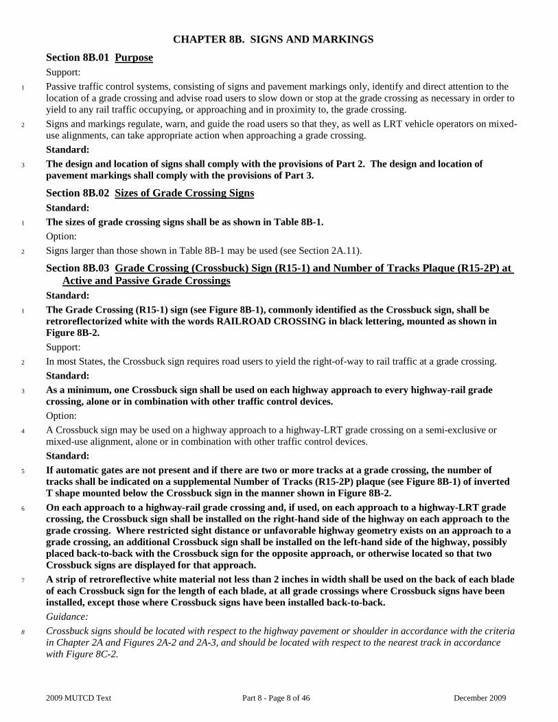
1 Passive traffic control systems, consisting of signs and pavement markings only, identify and direct attention to the location of a grade crossing and advise road users to slow down or stop at the grade crossing as necessary in order to yield to any rail traffic occupying, or approaching and in proximity to, the grade crossing.
2 Signs and markings regulate, warn, and guide the road users so that they, as well as LRT vehicle operators on mixed-use alignments, can take appropriate action when approaching a grade crossing. Standard:
3 The design and location of signs shall comply with the provisions of Part 2. The design and location of pavement markings shall comply with the provisions of Part 3.
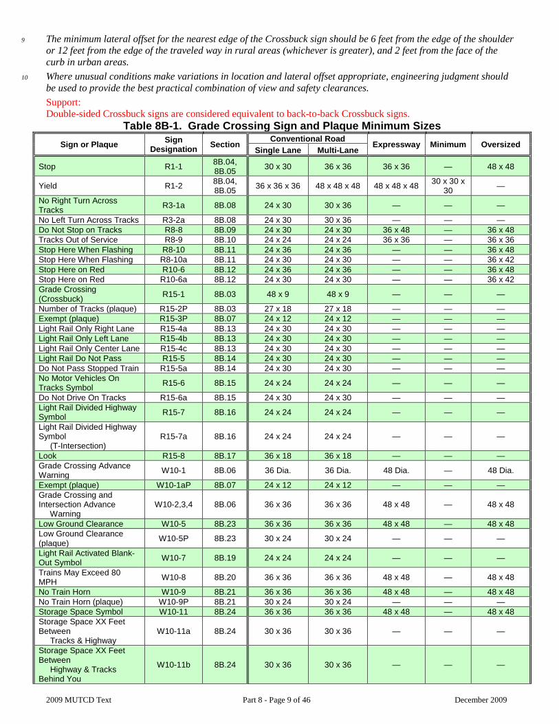
Section 8B.02 Sizes of Grade Crossing Signs Standard:
1 The sizes of grade crossing signs shall be as shown in Table 8B-1. Option:
2 Signs larger than those shown in Table 8B-1 may be used (see Section 2A.11).
Section 8B.03 Grade Crossing (Crossbuck) Sign (R15-1) and Number of Tracks Plaque (R15-2P) at Active and Passive Grade Crossings
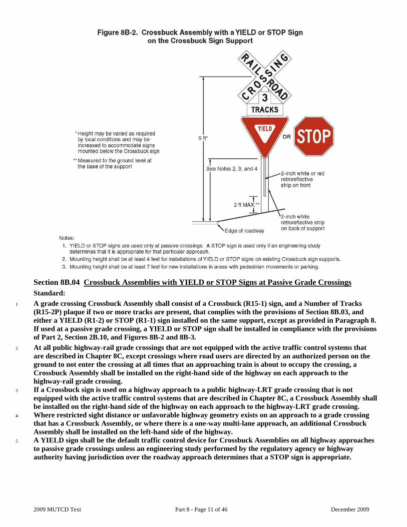
Standard: 1 The Grade Crossing (R15-1) sign (see Figure 8B-1), commonly identified as the Crossbuck sign, shall be
retroreflectorized white with the words RAILROAD CROSSING in black lettering, mounted as shown in Figure 8B-2. Support:
2 In most States, the Crossbuck sign requires road users to yield the right-of-way to rail traffic at a grade crossing. Standard:
3 As a minimum, one Crossbuck sign shall be used on each highway approach to every highway-rail grade crossing, alone or in combination with other traffic control devices. Option:
4 A Crossbuck sign may be used on a highway approach to a highway-LRT grade crossing on a semi-exclusive or mixed-use alignment, alone or in combination with other traffic control devices. Standard:
5 If automatic gates are not present and if there are two or more tracks at a grade crossing, the number of tracks shall be indicated on a supplemental Number of Tracks (R15-2P) plaque (see Figure 8B-1) of inverted T shape mounted below the Crossbuck sign in the manner shown in Figure 8B-2.
6 On each approach to a highway-rail grade crossing and, if used, on each approach to a highway-LRT grade crossing, the Crossbuck sign shall be installed on the right-hand side of the highway on each approach to the grade crossing. Where restricted sight distance or unfavorable highway geometry exists on an approach to a grade crossing, an additional Crossbuck sign shall be installed on the left-hand side of the highway, possibly placed back-to-back with the Crossbuck sign for the opposite approach, or otherwise located so that two Crossbuck signs are displayed for that approach.
7 A strip of retroreflective white material not less than 2 inches in width shall be used on the back of each blade of each Crossbuck sign for the length of each blade, at all grade crossings where Crossbuck signs have been installed, except those where Crossbuck signs have been installed back-to-back. Guidance:
8 Crossbuck signs should be located with respect to the highway pavement or shoulder in accordance with the criteria in Chapter 2A and Figures 2A-2 and 2A-3, and should be located with respect to the nearest track in accordance with Figure 8C-2.
2009 MUTCD Text Part 8 - Page 9 of 46 December 2009
9 The minimum lateral offset for the nearest edge of the Crossbuck sign should be 6 feet from the edge of the shoulder or 12 feet from the edge of the traveled way in rural areas (whichever is greater), and 2 feet from the face of the curb in urban areas.
10 Where unusual conditions make variations in location and lateral offset appropriate, engineering judgment should be used to provide the best practical combination of view and safety clearances. Support: Double-sided Crossbuck signs are considered equivalent to back-to-back Crossbuck signs.
Table 8B-1. Grade Crossing Sign and Plaque Minimum Sizes Sign or Plaque Sign
Designation Section Conventional Road Expressway Minimum Oversized Single Lane Multi-Lane
Stop R1-1 8B.04, 8B.05 30 x 30 36 x 36 36 x 36 — 48 x 48
Yield R1-2 8B.04, 8B.05 36 x 36 x 36 48 x 48 x 48 48 x 48 x 48 30 x 30 x
30 —
No Right Turn Across Tracks R3-1a 8B.08 24 x 30 30 x 36 — — —
No Left Turn Across Tracks R3-2a 8B.08 24 x 30 30 x 36 — — — Do Not Stop on Tracks R8-8 8B.09 24 x 30 24 x 30 36 x 48 — 36 x 48 Tracks Out of Service R8-9 8B.10 24 x 24 24 x 24 36 x 36 — 36 x 36 Stop Here When Flashing R8-10 8B.11 24 x 36 24 x 36 — — 36 x 48 Stop Here When Flashing R8-10a 8B.11 24 x 30 24 x 30 — — 36 x 42 Stop Here on Red R10-6 8B.12 24 x 36 24 x 36 — — 36 x 48 Stop Here on Red R10-6a 8B.12 24 x 30 24 x 30 — — 36 x 42 Grade Crossing (Crossbuck) R15-1 8B.03 48 x 9 48 x 9 — — —
Number of Tracks (plaque) R15-2P 8B.03 27 x 18 27 x 18 — — — Exempt (plaque) R15-3P 8B.07 24 x 12 24 x 12 — — — Light Rail Only Right Lane R15-4a 8B.13 24 x 30 24 x 30 — — — Light Rail Only Left Lane R15-4b 8B.13 24 x 30 24 x 30 — — — Light Rail Only Center Lane R15-4c 8B.13 24 x 30 24 x 30 — — — Light Rail Do Not Pass R15-5 8B.14 24 x 30 24 x 30 — — — Do Not Pass Stopped Train R15-5a 8B.14 24 x 30 24 x 30 — — — No Motor Vehicles On Tracks Symbol R15-6 8B.15 24 x 24 24 x 24 — — —
Do Not Drive On Tracks R15-6a 8B.15 24 x 30 24 x 30 — — — Light Rail Divided Highway Symbol R15-7 8B.16 24 x 24 24 x 24 — — —
Light Rail Divided Highway Symbol (T-Intersection)
R15-7a 8B.16 24 x 24 24 x 24 — — —
Look R15-8 8B.17 36 x 18 36 x 18 — — — Grade Crossing Advance Warning W10-1 8B.06 36 Dia. 36 Dia. 48 Dia. — 48 Dia.
Exempt (plaque) W10-1aP 8B.07 24 x 12 24 x 12 — — — Grade Crossing and Intersection Advance Warning
W10-2,3,4 8B.06 36 x 36 36 x 36 48 x 48 — 48 x 48
Low Ground Clearance W10-5 8B.23 36 x 36 36 x 36 48 x 48 — 48 x 48 Low Ground Clearance (plaque) W10-5P 8B.23 30 x 24 30 x 24 — — —
Light Rail Activated Blank-Out Symbol W10-7 8B.19 24 x 24 24 x 24 — — —
Trains May Exceed 80 MPH W10-8 8B.20 36 x 36 36 x 36 48 x 48 — 48 x 48
No Train Horn W10-9 8B.21 36 x 36 36 x 36 48 x 48 — 48 x 48 No Train Horn (plaque) W10-9P 8B.21 30 x 24 30 x 24 — — — Storage Space Symbol W10-11 8B.24 36 x 36 36 x 36 48 x 48 — 48 x 48 Storage Space XX Feet Between Tracks & Highway
W10-11a 8B.24 30 x 36 30 x 36 — — —
Storage Space XX Feet Between Highway & Tracks Behind You
W10-11b 8B.24 30 x 36 30 x 36 — — —

2009 MUTCD Text Part 8 - Page 10 of 46 December 2009
Skewed Crossing W10-12 8B.25 36 x 36 36 x 36 48 x 48 — 48 x 48 No Gates or Lights (plaque) W10-13P 8B.22 30 x 24 30 x 24 — — — Next Crossing (plaque) W10-14P 8B.23 30 x 24 30 x 24 — — — Use Next Crossing (plaque) W10-14aP 8B.23 30 x 24 30 x 24 — — — Rough Crossing (plaque) W10-15P 8B.23 30 x 24 30 x 24 — — 36 x 30 Notes: 1. Larger signs may be used when appropriate 2. Dimensions in inches are shown as width x height 3. Table 9B-1 shows the minimum sizes that may be used for grade crossing signs and plaques that face shared-use paths
and pedestrian facilities
2009 MUTCD Text Part 8 - Page 11 of 46 December 2009
Section 8B.04 Crossbuck Assemblies with YIELD or STOP Signs at Passive Grade Crossings Standard:
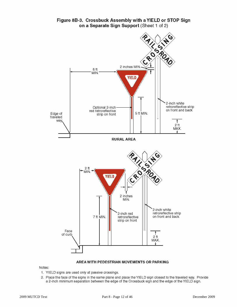
1 A grade crossing Crossbuck Assembly shall consist of a Crossbuck (R15-1) sign, and a Number of Tracks (R15-2P) plaque if two or more tracks are present, that complies with the provisions of Section 8B.03, and either a YIELD (R1-2) or STOP (R1-1) sign installed on the same support, except as provided in Paragraph 8. If used at a passive grade crossing, a YIELD or STOP sign shall be installed in compliance with the provisions of Part 2, Section 2B.10, and Figures 8B-2 and 8B-3.
2 At all public highway-rail grade crossings that are not equipped with the active traffic control systems that are described in Chapter 8C, except crossings where road users are directed by an authorized person on the ground to not enter the crossing at all times that an approaching train is about to occupy the crossing, a Crossbuck Assembly shall be installed on the right-hand side of the highway on each approach to the highway-rail grade crossing.
3 If a Crossbuck sign is used on a highway approach to a public highway-LRT grade crossing that is not equipped with the active traffic control systems that are described in Chapter 8C, a Crossbuck Assembly shall be installed on the right-hand side of the highway on each approach to the highway-LRT grade crossing.
4 Where restricted sight distance or unfavorable highway geometry exists on an approach to a grade crossing that has a Crossbuck Assembly, or where there is a one-way multi-lane approach, an additional Crossbuck Assembly shall be installed on the left-hand side of the highway.
5 A YIELD sign shall be the default traffic control device for Crossbuck Assemblies on all highway approaches to passive grade crossings unless an engineering study performed by the regulatory agency or highway authority having jurisdiction over the roadway approach determines that a STOP sign is appropriate.
2009 MUTCD Text Part 8 - Page 12 of 46 December 2009
2009 MUTCD Text Part 8 - Page 13 of 46 December 2009
Guidance:
2009 MUTCD Text Part 8 - Page 14 of 46 December 2009
1 The use of STOP signs at passive grade crossings should be limited to unusual conditions where requiring all highway vehicles to make a full stop is deemed essential by an engineering study. Among the factors that should be considered in the engineering study are the line of sight to approaching rail traffic (giving due consideration to seasonal crops or vegetation beyond both the highway and railroad or LRT rights-of-ways), the number of tracks, the speeds of trains or LRT equipment and highway vehicles, and the crash history at the grade crossing. Support:
2 Sections 8A.02 and 8A.03 contain information regarding the responsibilities of the highway agency and the railroad company or LRT agency regarding the selection, design, and operation of traffic control devices placed at grade crossings. Option:
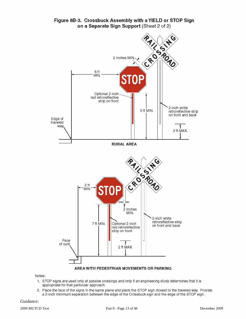
3 If a YIELD or STOP sign is installed for a Crossbuck Assembly at a grade crossing, it may be installed on the same support as the Crossbuck sign or it may be installed on a separate support at a point where the highway vehicle is to stop, or as near to that point as practical, but in either case, the YIELD or STOP sign is considered to be a part of the Crossbuck Assembly. Standard:
4 If a YIELD or STOP sign is installed on an existing Crossbuck sign support, the minimum height, measured vertically from the bottom of the YIELD or STOP sign to the top of the curb, or in the absence of curb, measured vertically from the bottom of the YIELD or STOP sign to the elevation of the near edge of the traveled way, shall be 4 feet (see Figure 8B-2).
5 If a Crossbuck Assembly is installed on a new sign support (see Figure 8B-2) or if the YIELD or STOP sign is installed on a separate support (see Figure 8B-3), the minimum height, measured vertically from the bottom of the YIELD or STOP sign to the top of the curb, or in the absence of curb, measured vertically from the bottom of the YIELD or STOP sign to the elevation of the near edge of the traveled way, shall be 7 feet if the Crossbuck Assembly is installed in an area where parking or pedestrian movements are likely to occur. Guidance:
6 If a YIELD or STOP sign is installed for a Crossbuck Assembly at a grade crossing on a separate support than the Crossbuck sign (see Figure 8B-3), the YIELD or STOP sign should be placed at a point where the highway vehicle is to stop, or as near to that point as practical, but no closer than 15 feet measured perpendicular from the nearest rail. The STOP sign should be placed on a separate post next to the railroad crossbuck sign whenever practical. Support:
7 The meaning of a Crossbuck Assembly that includes a YIELD sign is that a road user approaching the grade crossing needs to be prepared to decelerate, and when necessary, yield the right-of-way to any rail traffic that might be occupying the crossing or might be approaching and in such close proximity to the crossing that it would be unsafe for the road user to cross.
8 Certain commercial motor vehicles and school buses are required to stop at all grade crossings in accordance with 49 CFR 392.10 even if a YIELD sign (or just a Crossbuck sign) is posted.
9 The meaning of a Crossbuck Assembly that includes a STOP sign is that a road user approaching the grade crossing must come to a full and complete stop not less than 15 feet short of the nearest rail, and remain stopped while the road user determines if there is rail traffic either occupying the crossing or approaching and in such close proximity to the crossing that the road user must yield the right-of-way to rail traffic. The road user is permitted to proceed when it is safe to cross. Standard:
10 A vertical strip of retroreflective white material, not less than 2 inches in width, shall be used on each Crossbuck support at passive grade crossings for the full length of the back of the support from the Crossbuck sign or Number of Tracks plaque to within 2 feet above the ground, except as provided in Paragraph 16. Option:
11 The vertical strip of retroreflective material may be omitted from the back sides of Crossbuck sign supports installed on one-way streets.
12 If a YIELD or STOP sign is installed on the same support as the Crossbuck sign, a vertical strip of red (see Section 2A.21) or white retroreflective material that is at least 2 inches wide may be used on the front of the support from the YIELD or STOP sign to within 2 feet above the ground. Standard:
2009 MUTCD Text Part 8 - Page 15 of 46 December 2009
13 If a Crossbuck sign support at a passive grade crossing does not include a YIELD or STOP sign (either because the YIELD or STOP sign is placed on a separate support or because a YIELD or STOP sign is not present on the approach), a vertical strip of retroreflective white material, not less than 2 inches in width, shall be used for the full length of the front of the support from the Crossbuck sign or Number of Tracks plaque to within 2 feet above the ground.
14 At all grade crossings where YIELD or STOP signs are installed, Yield Ahead (W3-2) or Stop Ahead (W3-1) signs shall also be installed if the criteria for their installation in Section 2C.36 is met. Support:
15 Section 8B.28 contains provisions regarding the use of stop lines or yield lines at grade crossings.
STOP signs are the responsibility of the maintaining highway agency. Crossbuck signs are the responsibility of the railroad company. Maintenance issues arise when devices of separate responsibility are installed on the same support and need to be avoided when practical.
Section 8B.05 Use of STOP (R1-1) or YIELD (R1-2) Signs without Crossbuck Signs at Highway-LRT Grade Crossings
Standard: 1 For all highway-LRT grade crossings where only STOP (R1-1) or YIELD (R1-2) signs are installed, the
placement shall comply with the requirements of Section 2B.10. Stop Ahead (W3-1) or Yield Ahead (W3-2) Advance Warning signs (see Figure 2C-6) shall also be installed if the criteria for their installation given in Section 2C.36 is met. Guidance:
2 The use of only STOP or YIELD signs for road users at highway-LRT grade crossings should be limited to those crossings where the need and feasibility is established by an engineering study. Such crossings should have all of the following characteristics:
A. The crossing roadways should be secondary in character (such as a minor street with one lane in each direction, an alley, or a driveway) with low traffic volumes and low speed limits. The specific thresholds of traffic volumes and speed limits should be determined by the local agencies.
B. LRT speeds do not exceed 25 mph. C. The line of sight for an approaching LRT operator is adequate from a sufficient distance such that the
operator can sound an audible signal and bring the LRT equipment to a stop before arriving at the crossing. D. The road user has sufficient sight distance at the stop line to permit the vehicle to cross the tracks before the
arrival of the LRT equipment. E. If at an intersection of two roadways, the intersection does not meet the warrants for a traffic control signal
as provided in Chapter 4C. F. The LRT tracks are located such that highway vehicles are not likely to stop on the tracks while waiting to
enter a cross street or highway.
Section 8B.06 Grade Crossing Advance Warning Signs (W10 Series) Standard:
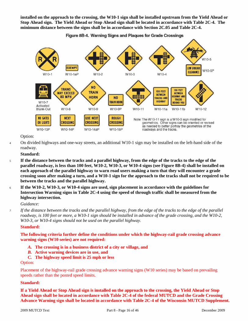
1 A Grade Crossing Advance Warning (W10-1) sign (see Figure 8B-4) shall be used on each highway in advance of every highway-rail grade crossing, and every highway-LRT grade crossing in semi-exclusive alignments, except in the following circumstances:
A. On an approach to a grade crossing from a T-intersection with a parallel highway if the distance from the edge of the track to the edge of the parallel roadway is less than 100 feet and W10-3 signs are used on both approaches of the parallel highway;
B. On low-volume, low-speed highways crossing minor spurs or other tracks that are infrequently used and road users are directed by an authorized person on the ground to not enter the crossing at all times that approaching rail traffic is about to occupy the crossing;
C. In business or commercial areas where active grade crossing traffic control devices are in use; or D. Where physical conditions do not permit even a partially effective display of the sign.
2 The placement of the Grade Crossing Advance Warning sign shall be in accordance with Section 2C.05 and Table 2C-4.
3 A Yield Ahead (W3-2) or Stop Ahead (W3-1) Advance Warning sign (see Figure 2C-6) shall also be installed if the criteria for their installation given in Section 2C.36 is met. If a Yield Ahead or Stop Ahead sign is
2009 MUTCD Text Part 8 - Page 16 of 46 December 2009
installed on the approach to the crossing, the W10-1 sign shall be installed upstream from the Yield Ahead or Stop Ahead sign. The Yield Ahead or Stop Ahead sign shall be located in accordance with Table 2C-4. The minimum distance between the signs shall be in accordance with Section 2C.05 and Table 2C-4.
Option:
4 On divided highways and one-way streets, an additional W10-1 sign may be installed on the left-hand side of the roadway. Standard:
5 If the distance between the tracks and a parallel highway, from the edge of the tracks to the edge of the parallel roadway, is less than 100 feet, W10-2, W10-3, or W10-4 signs (see Figure 8B-4) shall be installed on each approach of the parallel highway to warn road users making a turn that they will encounter a grade crossing soon after making a turn, and a W10-1 sign for the approach to the tracks shall not be required to be between the tracks and the parallel highway.
6 If the W10-2, W10-3, or W10-4 signs are used, sign placement in accordance with the guidelines for Intersection Warning signs in Table 2C-4 using the speed of through traffic shall be measured from the highway intersection. Guidance:
7 If the distance between the tracks and the parallel highway, from the edge of the tracks to the edge of the parallel roadway, is 100 feet or more, a W10-1 sign should be installed in advance of the grade crossing, and the W10-2, W10-3, or W10-4 signs should not be used on the parallel highway. Standard:
The following criteria further define the conditions under which the highway-rail grade crossing advance warning signs (W10 series) are not required:
A. The crossing is in a business district of a city or village, and B. Active warning devices are in use, and C. The highway speed limit is 25 mph or less
Option:
Placement of the highway-rail grade crossing advance warning signs (W10 series) may be based on prevailing speeds rather than the posted speed limits.
Standard:
If a Yield Ahead or Stop Ahead sign is installed on the approach to the crossing, the Yield Ahead or Stop Ahead sign shall be located in accordance with Table 2C-4 of the federal MUTCD and the Grade Crossing Advance Warning sign shall be located in accordance with Table 2C-4 of the Wisconsin MUTCD Supplement.
2009 MUTCD Text Part 8 - Page 17 of 46 December 2009
Section 8B.07 EXEMPT Grade Crossing Plaques (R15-3P, W10-1aP) Option:
1 When authorized by law or regulation, a supplemental EXEMPT (R15-3P) plaque (see Figure 8B-1) with a white background may be used below the Crossbuck sign or Number of Tracks plaque, if present, at the grade crossing, and a supplemental EXEMPT (W10-1aP) plaque (see Figure 8B-4) with a yellow background may be used below the Grade Crossing Advance Warning (W10 series) sign.
2 Where neither the Crossbuck sign nor the advance warning signs exist for a particular highway-LRT grade crossing, an EXEMPT (R15-3P) plaque with a white background may be placed on its own post on the near right-hand side of the approach to the crossing. Support:
3 These supplemental plaques inform drivers of highway vehicles carrying passengers for hire, school buses carrying students, or highway vehicles carrying hazardous materials that a stop is not required at certain designated grade crossings, except when rail traffic is approaching or occupying the grade crossing, or the driver’s view is blocked. Standard:
The EXEMPT highway-rail grade crossing plaques (R15-3P, W10-1aP) shall be placed at crossings within the control limits of a highway traffic signal (typically defined as the area between the near right signals) or shall only be used when specifically authorized by order of the Commissioner of Railroads.
Support:
Wisconsin State Statute 346.45 (3)(b) exempts vehicles at crossings that are controlled by traffic signals. Wisconsin State Statute 195.285 states that the Commissioner of Railroads has regulatory authority over the use of the EXEMPT plaques.
Section 8B.08 Turn Restrictions During Preemption Guidance:
1 At a signalized intersection that is located within 100 200 feet of a highway-rail grade crossing, measured from the edge of the track to the edge of the roadway, where the intersection traffic control signals are preempted by the approach of a train, all existing turning movements toward the highway-rail grade crossing should be prohibited during the signal preemption sequences. This also includes the prohibition of U Turns Option:
2 A blank-out or changeable message sign and/or appropriate highway traffic signal indication or other similar type sign may be used to prohibit turning movements toward the highway-rail grade crossing during preemption. The R3-1a and R3-2a signs shown in Figure 8B-1 may be used for this purpose. Support:
3 LRT operations can include the use of activated blank-out sign technology for turn prohibition signs. The signs are typically used on roads paralleling a semi-exclusive or mixed-use LRT alignment where road users might turn across the LRT tracks. A blank-out sign displays its message only when activated. When not activated, the sign face is blank. Guidance:
4 An LRT-activated blank-out turn prohibition (R3-1a or R3-2a) sign should be used where an intersection adjacent to a highway-LRT crossing is controlled by STOP signs, or is controlled by traffic control signals with permissive turn movements for road users crossing the tracks. Option:
5 An LRT-activated blank-out turn prohibition (R3-1a or R3-2a) sign may be used for turning movements that cross the tracks.
6 As an alternative to LRT-activated blank-out turn prohibition signs at intersections with traffic control signals, exclusive traffic control signal phases such that all movements that cross the tracks have a steady red indication may be used in combination with No Turn on Red (R10-11, R10-11a, or R10-11b) signs (see Section 2B.53). Standard:
7 Turn prohibition signs that are associated with preemption shall be visible or activated only when the grade crossing restriction is in effect.
Section 8B.09 DO NOT STOP ON TRACKS Sign (R8-8)
2009 MUTCD Text Part 8 - Page 18 of 46 December 2009
Guidance: 1 A DO NOT STOP ON TRACKS (R8-8) sign (see Figure 8B-1) should be installed whenever an engineering study
determines that the potential for highway vehicles stopping on the tracks at a grade crossing is significant. Placement of the R8-8 sign should be determined as part of the engineering study. The sign, if used, should be located on the right-hand side of the highway on either the near or far side of the grade crossing, depending upon which position provides better visibility to approaching drivers.
2 If a STOP or YIELD sign is installed at a location, including at a circular intersection, that is downstream from the grade crossing such that highway vehicle queues are likely to extend beyond the tracks, a DO NOT STOP ON TRACKS sign (R8-8) should be used. Option:
3 DO NOT STOP ON TRACKS signs may be placed on both sides of the track. 4 On divided highways and one-way streets, a second DO NOT STOP ON TRACKS sign may be placed on the near
or far left-hand side of the highway at the grade crossing to further improve visibility of the sign.
Section 8B.10 TRACKS OUT OF SERVICE Sign (R8-9) Guidance Option:
1 The TRACKS OUT OF SERVICE (R8-9) sign (see Figure 8B-1) should may be used at a grade crossing instead of a Crossbuck (R15-1) sign and a Number of Tracks (R15-2P) plaque or instead of a Crossbuck Assembly when railroad or LRT tracks have been temporarily or permanently abandoned or taken out of service, but only until such time that the tracks are removed or covered. Standard:
2 When tracks are out of service, traffic control devices and gate arms shall be removed and the signal heads shall be removed or hooded or turned from view to clearly indicate that they are not in operation.
3 The R8-9 sign shall be removed when the tracks have been removed or covered or when the grade crossing is returned to service.
Section 8B.11 STOP HERE WHEN FLASHING Sign (R8-10, R8-10a) Option:
1 The STOP HERE WHEN FLASHING (R8-10, R8-10a) sign (see Figure 8B-1) may be used at a grade crossing to inform drivers of the location of the stop line or the point at which to stop when the flashing-light signals (see Section 8C.02) are activated.
Section 8B.12 STOP HERE ON RED Sign (R10-6, R10-6a) Support:
1 The STOP HERE ON RED (R10-6, R10-6a) sign (see Figure 8B-1) defines and facilitates observance of stop lines at traffic control signals. Option:
2 A STOP HERE ON RED sign may be used at locations where highway vehicles frequently violate the stop line or where it is not obvious to road users where to stop. Guidance:
3 If possible, stop lines should be placed at a point where the highway vehicle driver has adequate sight distance along the track.
Section 8B.13 Light Rail Transit Only Lane Signs (R15-4 Series) Support:
1 The Light Rail Transit Only Lane (R15-4 series) signs (see Figure 8B-1) are used for multi-lane operations, where road users might need additional guidance on lane use and/or restrictions. Option:
2 Light Rail Transit Only Lane signs may be used on a roadway lane limited to only LRT use to indicate the restricted use of a lane in semi-exclusive and mixed alignments. Guidance:
2009 MUTCD Text Part 8 - Page 19 of 46 December 2009
3 If used, the R15-4a, R15-4b, and R15-4c signs should be installed on posts adjacent to the roadway containing the LRT tracks or overhead above the LRT only lane. Option:
4 If the trackway is paved, preferential lane markings (see Chapter 3D) may be installed but only in combination with Light Rail Transit Only Lane signs. Support:
5 The trackway is the continuous way designated for LRT, including the entire dynamic envelope. Section 8B.29 contains more information regarding the dynamic envelope.
Section 8B.14 Do Not Pass Light Rail Transit Signs (R15-5, R15-5a) Support:
1 A Do Not Pass Light Rail Transit (R15-5) sign (see Figure 8B-1) is used to indicate that motor vehicles are not allowed to pass LRT vehicles that are loading or unloading passengers where there is no raised platform or physical separation from the lanes upon which other motor vehicles are operating. Option:
2 The R15-5 sign may be used in mixed-use alignments and may be mounted overhead where there are multiple lanes. 3 Instead of the R15-5 symbol sign, a regulatory sign with the word message DO NOT PASS STOPPED TRAIN
(R15-5a) may be used (see Figure 8B-1). Guidance:
4 If used, the R15-5 sign should be located immediately before the LRT boarding area.
Section 8B.15 No Motor Vehicles On Tracks Signs (R15-6, R15-6a) Support:
1 The No Motor Vehicles On Tracks (R15-6) sign (see Figure 8B-1) is used where there are adjacent traffic lanes separated from the LRT lane by a curb or pavement markings. Guidance:
2 The DO NOT ENTER (R5-1) sign should be used where a road user could wrongly enter an LRT only street. Option:
3 A No Motor Vehicles On Tracks sign may be used to deter motor vehicles from driving on the trackway. It may be installed on a 3-foot flexible post between double tracks, on a post alongside the tracks, or overhead.
4 Instead of the R15-6 symbol sign, a regulatory sign with the word message DO NOT DRIVE ON TRACKS (R15-6a) may be used (see Figure 8B-1).
5 A reduced size of 12 x 12 inches may be used if the R15-6 sign is installed between double tracks. Standard:
6 The smallest size for the R15-6 sign shall be 12 x 12 inches.
Section 8B.16 Divided Highway with Light Rail Transit Crossing Signs (R15-7 Series) Option:
1 The Divided Highway with Light Rail Transit Crossing (R15-7) sign (see Figure 8B-1) may be used as a supplemental sign on the approach legs of a roadway that intersects with a divided highway where LRT equipment operates in the median. The sign may be placed beneath a STOP sign or mounted separately. Guidance:
2 The number of tracks displayed on the R15-7 sign should be the same as the actual number of tracks. Standard:
3 When the Divided Highway With Light Rail Transit Crossing sign is used at a four-legged intersection, the R15-7 sign shall be used. When used at a T-intersection, the R15-7a sign shall be used.
Section 8B.17 LOOK Sign (R15-8) Option:
2009 MUTCD Text Part 8 - Page 20 of 46 December 2009
1 At grade crossings, the LOOK (R15-8) sign (see Figure 8B-1) may be mounted as a supplemental plaque on the Crossbuck support, or on a separate post in the immediate vicinity of the grade crossing on the railroad or LRT right-of-way. Guidance:
2 A LOOK sign should not be mounted as a supplemental plaque on a Crossbuck Assembly that has a YIELD or STOP sign mounted on the same support as the Crossbuck. Standard:
Except at station crossings, the LOOK sign (R15-8) shall not be used.
Support:
Since drivers need to look at all crossings, the LOOK sign would have to be placed at all highway-rail grade crossings to avoid inconsistent messages being conveyed to drivers. It would be impractical to require the LOOK sign at all grade crossings.
Section 8B.18 Emergency Notification Sign (I-13) Guidance:
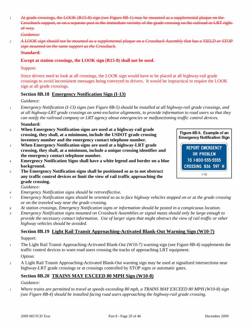
1 Emergency Notification (I-13) signs (see Figure 8B-5) should be installed at all highway-rail grade crossings, and at all highway-LRT grade crossings on semi-exclusive alignments, to provide information to road users so that they can notify the railroad company or LRT agency about emergencies or malfunctioning traffic control devices. Standard:
2 When Emergency Notification signs are used at a highway-rail grade crossing, they shall, at a minimum, include the USDOT grade crossing inventory number and the emergency contact telephone number.
3 When Emergency Notification signs are used at a highway-LRT grade crossing, they shall, at a minimum, include a unique crossing identifier and the emergency contact telephone number.
4 Emergency Notification Signs shall have a white legend and border on a blue background.
5 The Emergency Notification signs shall be positioned so as to not obstruct any traffic control devices or limit the view of rail traffic approaching the grade crossing. Guidance:
6 Emergency Notification signs should be retroreflective. 7 Emergency Notification signs should be oriented so as to face highway vehicles stopped on or at the grade crossing
or on the traveled way near the grade crossing. 8 At station crossings, Emergency Notification signs or information should be posted in a conspicuous location. 9 Emergency Notification signs mounted on Crossbuck Assemblies or signal masts should only be large enough to
provide the necessary contact information. Use of larger signs that might obstruct the view of rail traffic or other highway vehicles should be avoided.
Section 8B.19 Light Rail Transit Approaching-Activated Blank-Out Warning Sign (W10-7) Support:
1 The Light Rail Transit Approaching-Activated Blank-Out (W10-7) warning sign (see Figure 8B-4) supplements the traffic control devices to warn road users crossing the tracks of approaching LRT equipment. Option:
2 A Light Rail Transit Approaching-Activated Blank-Out warning sign may be used at signalized intersections near highway-LRT grade crossings or at crossings controlled by STOP signs or automatic gates.
Section 8B.20 TRAINS MAY EXCEED 80 MPH Sign (W10-8) Guidance:
1 Where trains are permitted to travel at speeds exceeding 80 mph, a TRAINS MAY EXCEED 80 MPH (W10-8) sign (see Figure 8B-4) should be installed facing road users approaching the highway-rail grade crossing.
2009 MUTCD Text Part 8 - Page 21 of 46 December 2009
2 If used, the TRAINS MAY EXCEED 80 MPH signs should be installed between the Grade Crossing Advance Warning (W10 series) sign (see Figure 8B-4) and the highway-rail grade crossing on all approaches to the highway-rail grade crossing. The locations should be determined based on specific site conditions.
Section 8B.21 NO TRAIN HORN Sign or Plaque (W10-9, W10-9P) Standard:
1 Either a NO TRAIN HORN (W10-9) sign (see Figure 8B-4) or a NO TRAIN HORN (W10-9P) plaque shall be installed in each direction at each highway-rail grade crossing where a quiet zone has been established in compliance with 49 CFR Part 222. If a W10-9P plaque is used, it shall supplement and be mounted directly below the Grade Crossing Advance Warning (W10 series) sign (see Figure 8B-4).
Section 8B.22 NO GATES OR LIGHTS Plaque (W10-13P) Option:
1 The NO GATES OR LIGHTS (W10-13P) plaque (see Figure 8B-4) may be mounted below the Grade Crossing Advance Warning (W10 series) sign at grade crossings that are not equipped with automated signals. Standard:
The NO GATES OR LIGHTS plaque (W10-13P) shall not be placed at highway-rail or pathway grade crossings.
Support:
The NO GATES OR LIGHTS plaque would have to be placed at all passive grade crossings to avoid inconsistent messages being conveyed to drivers. It would be impractical to require the NO LIGHTS OR GATES plaque at all passive grade crossings.
Section 8B.23 Low Ground Clearance Grade Crossing Sign (W10-5) Guidance:
1 If the highway profile conditions are sufficiently abrupt to create a hang-up situation for long wheelbase vehicles or for trailers with low ground clearance, the Low Ground Clearance Grade Crossing (W10-5) sign (see Figure 8B-4) should be installed in advance of the grade crossing. Standard:
2 Because this symbol might not be readily recognizable by the public, the Low Ground Clearance Grade Crossing (W10-5) warning sign shall be accompanied by an educational plaque, LOW GROUND CLEARANCE. The LOW GROUND CLEARANCE educational plaque shall remain in place for at least 3 years after the initial installation of the W10-5 sign (see Section 2A.12). Guidance:
3 Auxiliary plaques such as AHEAD, NEXT CROSSING, or USE NEXT CROSSING (with appropriate arrows), or a supplemental distance plaque should be placed below the W10-5 sign at the nearest intersecting highway where a vehicle can detour or at a point on the highway wide enough to permit a U-turn.
4 If engineering judgment of roadway geometric and operating conditions confirms that highway vehicle speeds across the tracks should be below the posted speed limit, a W13-1P advisory speed plaque should be posted. Option:
5 If the grade crossing is rough, word message signs such as BUMP, DIP, or ROUGH CROSSING may be installed. A W13-1P advisory speed plaque may be installed below the word message sign in advance of rough crossings. Support:
6 Information on ground clearance requirements at grade crossings is available in the “American Railway Engineering and Maintenance-of-Way Association’s Engineering Manual,” or the American Association of State Highway and Transportation Officials’ “Policy on Geometric Design of Highways and Streets” (see Section 1A.11).
Section 8B.24 Storage Space Signs (W10-11, W10-11a, W10-11b) Guidance:
1 A Storage Space (W10-11) sign supplemented by a word message storage distance (W10-11a) sign (see Figure 8B-4) should be used where there is a highway intersection in close proximity to the grade crossing and an engineering study determines that adequate space is not available to store a design vehicle(s) between the highway intersection and the train or LRT equipment dynamic envelope.

2009 MUTCD Text Part 8 - Page 22 of 46 December 2009
2 If used tThe Storage Space (W10-11 and W10-11a) signs should be mounted in advance of the grade crossing at an appropriate location to advise drivers of the space available for highway vehicle storage between the highway intersection and the grade crossing. Option:
3 A Storage Space (W10-11b) sign (see Figure 8B-4) may be mounted beyond the grade crossing at the highway intersection under the STOP or YIELD sign or just prior to the signalized intersection to remind drivers of the storage space between the tracks and the highway intersection. The Storage Space (W10-11 and W10-11a) signs are optional based on engineering judgment for reasons such as sign clutter or other physical limitations. Section 8B.25 Skewed Crossing Sign (W10-12) Option:
1 The Skewed Crossing (W10-12) sign (see Figure 8B-4) may be used at a skewed grade crossing to warn road users that the tracks are not perpendicular to the highway. Guidance:
2 If the Skewed Crossing sign is used, the symbol should show the direction of the crossing (near left to far right as shown in Figure 8B-4, or the mirror image if the track goes from far left to near right). If the Skewed Crossing sign is used where the angle of the crossing is significantly different than 45 degrees, the symbol should show the approximate angle of the crossing. Standard:
3 The Skewed Crossing sign shall not be used as a replacement for the required Advance Warning (W10-1) sign. If used, the Skewed Crossing sign shall supplement the W10-1 sign and shall be mounted on a separate post.
Section 8B.26 Light Rail Transit Station Sign (I-12) Option:
1 The Light Rail Transit Station (I-12) sign (see Figure 2H-1) may be used to direct road users to an LRT station or boarding location. It may be supplemented by the name of the transit system and by arrows as provided in Section 2D.08.
Section 8B.27 Pavement Markings Standard:
1 All grade crossing pavement markings shall be retroreflectorized white. All other markings shall be in accordance with Part 3.
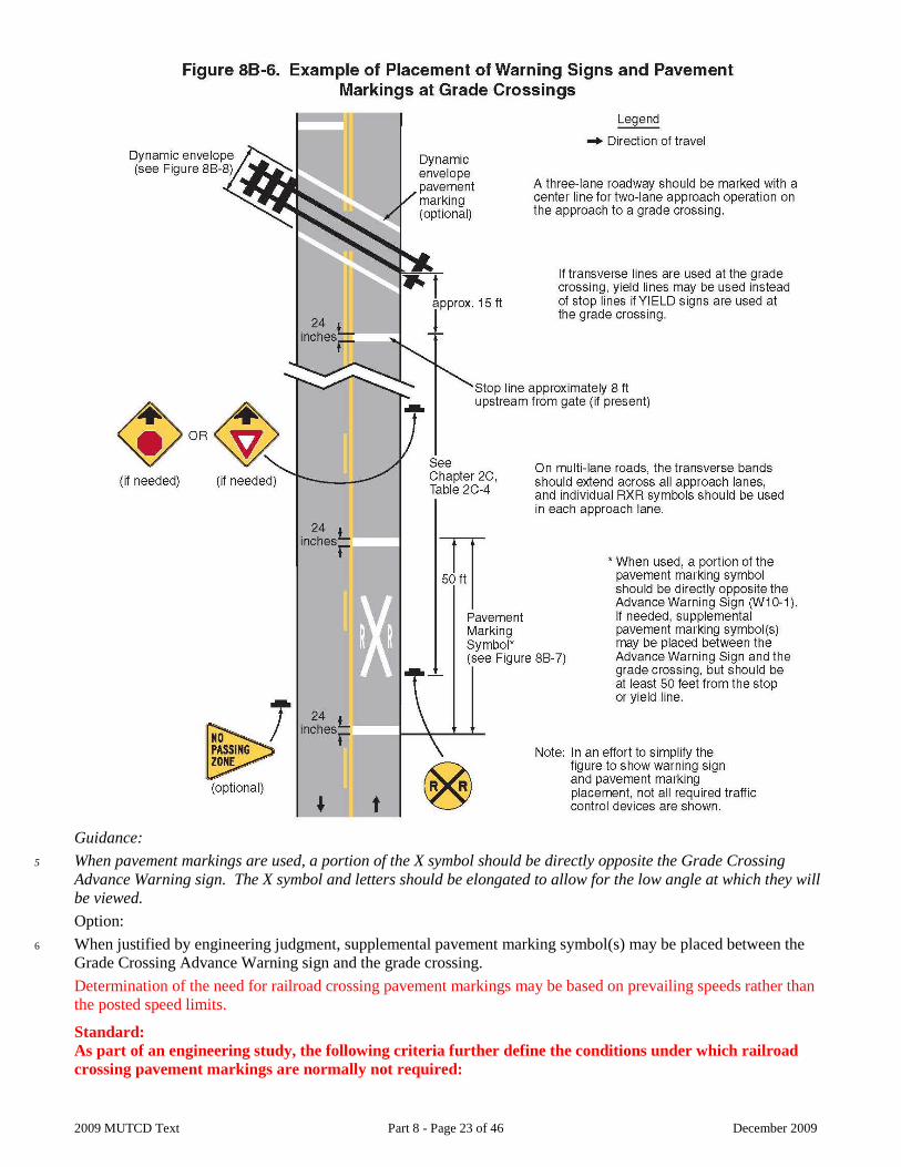
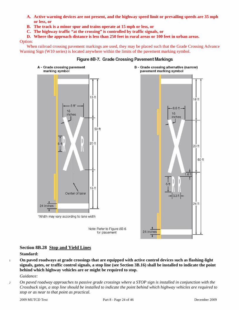
2 On paved roadways, pavement markings in advance of a grade crossing shall consist of an X, the letters RR, a no-passing zone marking (on two-lane, two-way highways with center line markings in compliance with Section 3B.01), and certain transverse lines as shown in Figures 8B-6 and 8B-7.
3 Identical markings shall be placed in each approach lane on all paved approaches to grade crossings where signals or automatic gates are located, and at all other grade crossings where the posted or statutory highway speed is 40 mph or greater.
4 Pavement markings shall not be required at grade crossings where the posted or statutory highway speed is less than 40 mph if an engineering study indicates that other installed devices provide suitable warning and control. Pavement markings shall not be required at grade crossings in urban areas if an engineering study indicates that other installed devices provide suitable warning and control.
2009 MUTCD Text Part 8 - Page 23 of 46 December 2009
Guidance:
5 When pavement markings are used, a portion of the X symbol should be directly opposite the Grade Crossing Advance Warning sign. The X symbol and letters should be elongated to allow for the low angle at which they will be viewed. Option:
6 When justified by engineering judgment, supplemental pavement marking symbol(s) may be placed between the Grade Crossing Advance Warning sign and the grade crossing. Determination of the need for railroad crossing pavement markings may be based on prevailing speeds rather than the posted speed limits. Standard: As part of an engineering study, the following criteria further define the conditions under which railroad crossing pavement markings are normally not required:
2009 MUTCD Text Part 8 - Page 24 of 46 December 2009
A. Active warning devices are not present, and the highway speed limit or prevailing speeds are 35 mph or less, or
B. The track is a minor spur and trains operate at 15 mph or less, or C. The highway traffic “at the crossing” is controlled by traffic signals, or D. Where the approach distance is less than 250 feet in rural areas or 100 feet in urban areas.
Option: When railroad crossing pavement markings are used, they may be placed such that the Grade Crossing Advance
Warning Sign (W10 series) is located anywhere within the limits of the pavement marking symbol.
Section 8B.28 Stop and Yield Lines Standard:
1 On paved roadways at grade crossings that are equipped with active control devices such as flashing-light signals, gates, or traffic control signals, a stop line (see Section 3B.16) shall be installed to indicate the point behind which highway vehicles are or might be required to stop. Guidance:
2 On paved roadway approaches to passive grade crossings where a STOP sign is installed in conjunction with the Crossbuck sign, a stop line should be installed to indicate the point behind which highway vehicles are required to stop or as near to that point as practical.
2009 MUTCD Text Part 8 - Page 25 of 46 December 2009
3 If a stop line is used, it should be a transverse line at a right angle to the traveled way and should be placed approximately 8 feet in advance of the gate (if present), but no closer than 15 feet in advance of the nearest rail. Option:
4 On paved roadway approaches to passive grade crossings where a YIELD sign is installed in conjunction with the Crossbuck sign, a yield line (see Section 3B.16) or a stop line may be installed to indicate the point behind which highway vehicles are required to yield or stop or as near to that point as practical. Guidance:
5 If a yield line is used, it should be a transverse line (see Figure 3B-16) at a right angle to the traveled way and should be placed no closer than 15 feet in advance of the nearest rail (see Figure 8B-7).
Section 8B.29 Dynamic Envelope Markings Support:
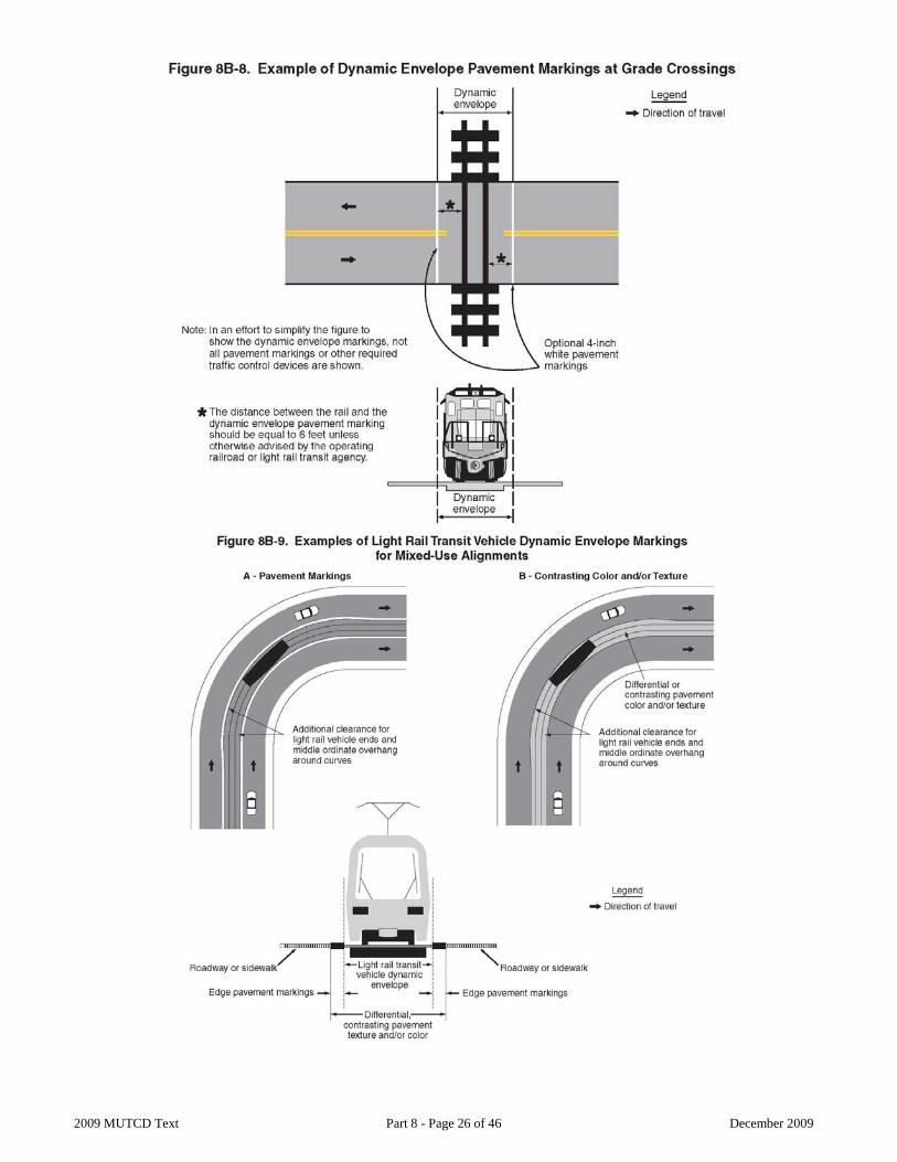
1 The dynamic envelope (see Figures 8B-8 and 8B-9) markings indicate the clearance required for the train or LRT equipment overhang resulting from any combination of loading, lateral motion, or suspension failure. Option:
2 Dynamic envelope markings may be installed at all grade crossings, unless a Four-Quadrant Gate system (see Section 8C.06) is used. Standard:
3 If used, pavement markings for indicating the dynamic envelope shall comply with the provisions of Part 3 and shall be a 4-inch normal solid white line or contrasting pavement color and/or contrasting pavement texture. Guidance:
4 If pavement markings are used to convey the dynamic envelope, they should be placed completely outside of the dynamic envelope. If used, dynamic envelope pavement markings should be placed on the highway 6 feet from and parallel to the nearest rail unless the operating railroad company or LRT agency advises otherwise. The pavement markings should extend across the roadway as shown in Figure 8B-8. The dynamic envelope pavement markings should not be placed perpendicular to the roadway at skewed grade crossings. Option:
5 In semi-exclusive LRT alignments, the dynamic envelope markings may be along the LRT trackway between intersections where the trackway is immediately adjacent to travel lanes and no physical barrier is present.
6 In mixed-use LRT alignments, the dynamic envelope markings may be continuous between intersections (see Figure 8B-9).
7 In mixed-use LRT alignments, pavement markings for adjacent travel or parking lanes may be used instead of dynamic envelope markings if the lines are outside the dynamic envelope. Guidance:
Supplemental markings should be used between the outline markings of the dynamic envelope. When dynamic envelope pavement markings are used, the DO NOT STOP ON TRACKS (R8-8) sign or storage space sign (W10-11a) should be used.
Standard:
If used, the supplemental markings shall be 12-inch white diagonals at a 45-degree angle and 5-foot spacing.
2009 MUTCD Text Part 8 - Page 26 of 46 December 2009
2009 MUTCD Text Part 8 - Page 27 of 46 December 2009
CHAPTER 8C. FLASHING-LIGHT SIGNALS, GATES, AND TRAFFIC CONTROL SIGNALS Section 8C.01 Introduction Support:
1 Active traffic control systems inform road users of the approach or presence of rail traffic at grade crossings. These systems include four-quadrant gate systems, automatic gates, flashing-light signals, traffic control signals, actuated blank-out and variable message signs, and other active traffic control devices.
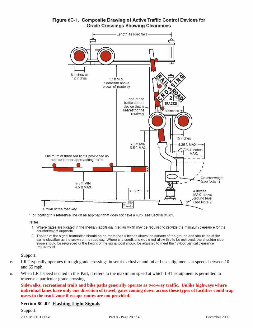
2 A composite drawing (see Figure 8C-1) shows a post-mounted flashing-light signal (two light units mounted in a horizontal line), a flashing-light signal mounted on an overhead structure, and an automatic gate assembly. Option:
3 Post-mounted and overhead flashing-light signals may be used separately or in combination with each other as determined by an engineering study. Also, flashing-light signals may be used without automatic gate assemblies, as determined by an engineering study. Standard:
4 The meaning of flashing-light signals and gates shall be as stated in the “Uniform Vehicle Code” (see Sections 11-701 and 11-703 of the UVC), which is available from the National Committee on Uniform Traffic Laws and Ordinances (see Page i for the address). When active warning devices have been installed, the operative parts shall remain covered or turned until the time the device is placed in regular and continuous service.
5 Location and clearance dimensions for flashing-light signals and gates shall be as shown in Figure 8C-1. 6 When there is a curb, a horizontal offset of at least 2 feet shall be provided from the face of the vertical curb
to the closest part of the signal or gate arm in its upright position. When a cantilevered-arm flashing-light signal is used, the vertical clearance shall be at least 17 feet above the crown of the highway to the lowest point of the signal unit.
7 Where there is a shoulder, but no curb, a horizontal offset of at least 2 feet from the edge of a paved or surfaced shoulder shall be provided, with an offset of at least 6 feet from the edge of the traveled way.
8 Where there is no curb or shoulder, the minimum horizontal offset shall be 6 feet from the edge of the traveled way. Guidance:
9 Equipment housings (controller cabinets) should have a lateral offset of at least 30 feet from the edge of the highway, and where railroad or LRT property and conditions allow, at least 25 feet from the nearest rail.
10 If a pedestrian route is provided, sufficient clearance from supports, posts, and gate mechanisms should be maintained for pedestrian travel. Automatic gates are not recommended across sidewalks, recreational trails or bike paths unless the crossing and warning devices are designed to provide an escape route.
11 When determined by an engineering study, a lateral escape route to the right of the highway in advance of the grade crossing traffic control devices should be kept free of guardrail or other ground obstructions. Where guardrail is not deemed necessary or appropriate, barriers should not be used for protecting signal supports.
12 The same lateral offset and roadside safety features should apply to flashing-light signal and automatic gate locations on both the right-hand and left-hand sides of the roadway. Option:
13 In industrial or other areas involving only low-speed highway traffic or where signals are vulnerable to damage by turning truck traffic, guardrail may be installed to provide protection for the signal assembly. Guidance:
14 Where both traffic control signals and flashing-light signals (with or without automatic gates) are in operation at the same highway-LRT grade crossing, the operation of the devices should be coordinated to avoid any display of conflicting signal indications.
2009 MUTCD Text Part 8 - Page 28 of 46 December 2009
Support:
15 LRT typically operates through grade crossings in semi-exclusive and mixed-use alignments at speeds between 10 and 65 mph.
16 When LRT speed is cited in this Part, it refers to the maximum speed at which LRT equipment is permitted to traverse a particular grade crossing. Sidewalks, recreational trails and bike paths generally operate as two-way traffic. Unlike highways where individual lanes have only one direction of travel, gates coming down across these types of facilities could trap users in the track zone if escape routes are not provided.
Section 8C.02 Flashing-Light Signals Support:
2009 MUTCD Text Part 8 - Page 29 of 46 December 2009
1 Section 8C.03 contains additional information regarding flashing-light signals at highway-LRT grade crossings in semi-exclusive and mixed-use alignments. Standard:
2 If used, the flashing-light signal assembly (shown in Figure 8C-1) on the side of the highway shall include a standard Crossbuck (R15-1) sign, and where there is more than one track, a supplemental Number of Tracks (R15-2P) plaque, all of which indicate to motorists, bicyclists, and pedestrians the location of a grade crossing. Option:
3 At highway-rail grade crossings, bells or other audible warning devices may be included in the assembly and may be operated in conjunction with the flashing lights to provide additional warning for pedestrians, bicyclists, and/or other non-motorized road users. Standard:
4 When indicating the approach or presence of rail traffic, the flashing-light signal shall display toward approaching highway traffic two red lights mounted in a horizontal line flashing alternately.
5 If used, flashing-light signals shall be placed to the right of approaching highway traffic on all highway approaches to a grade crossing. They shall be located laterally with respect to the highway in compliance with Figure 8C-1 except where such location would adversely affect signal visibility.
6 If used at a grade crossing with highway traffic in both directions, back-to-back pairs of lights shall be placed on each side of the tracks. On multi-lane one-way streets and divided highways, flashing-light signals shall be placed on the approach side of the grade crossing on both sides of the roadway or shall be placed above the highway.
7 Each red signal unit in the flashing-light signal shall flash alternately. The number of flashes per minute for each lamp shall be 35 minimum and 65 maximum. Each lamp shall be illuminated approximately the same length of time. Total time of illumination of each pair of lamps shall be the entire operating time. Flashing-light units shall use either 8-inch or 12-inch nominal diameter lenses. Guidance:
8 In choosing between the 8-inch or 12-inch nominal diameter lenses for use in grade crossing flashing-light signals, consideration should be given to the principles stated in Section 4D.07. Standard:
9 Grade crossing flashing-light signals shall operate at a low voltage using storage batteries either as a primary or stand-by source of electrical energy. Provision shall be made to provide a source of energy for charging batteries. Option:
10 Additional pairs of flashing-light units may be mounted on the same supporting post and directed toward vehicular traffic approaching the grade crossing from other than the principal highway route, such as where there are approaching routes on highways closely adjacent to and parallel to the track(s). Standard:
11 References to lenses in this Section shall not be used to limit flashing-light signal optical units to incandescent lamps within optical assemblies that include lenses. Support:
12 Research has resulted in flashing-light signal optical units that are not lenses, such as, but not limited to, light emitting diode (LED) flashing-light signal modules. Option:
13 Flashing-light signals may be installed on overhead structures or cantilevered supports as shown in Figure 8C-1 where needed for additional emphasis, or for better visibility to approaching traffic, particularly on multi-lane approaches or highways with profile restrictions. Additional Crossbuck signs may be used on overhead structures or cantilevered supports to supplement the side of highway mounted signs. The Number of Tracks plaque may be used in conjunction with the supplemental Crossbuck but is not required.
14 If it is determined by an engineering study that one set of flashing lights on the cantilever arm is not sufficiently visible to road users, one or more additional sets of flashing lights may be mounted on the supporting post and/or on the cantilever arm. Standard:
2009 MUTCD Text Part 8 - Page 30 of 46 December 2009
15 Breakaway or frangible bases shall not be used for overhead structures or cantilevered supports. 16 Except as otherwise provided in Paragraphs 13 through 15, flashing-light signals mounted overhead shall
comply with the applicable provisions of this Section.
Section 8C.03 Flashing-Light Signals at Highway-LRT Grade Crossings Support:
1 Section 8C.02 contains additional provisions regarding the design and operation of flashing-light signals, including those installed at highway-LRT grade crossings. Standard:
2 Highway-LRT grade crossings in semi-exclusive alignments shall be equipped with flashing-light signals where LRT speeds exceed 35 mph. Flashing-light signals shall be clearly visible to motorists, pedestrians, and bicyclists.
3 If flashing-light signals are in operation at a highway-LRT crossing that is used by pedestrians, bicyclists, and/or other non-motorized road users, an audible device such as a bell shall also be provided and shall be operated in conjunction with the flashing-light signals. Guidance:
4 Where the crossing is at a location other than an intersection and LRT speeds exceed 25 mph, flashing-light signals should be installed. Option:
5 Traffic control signals may be used instead of flashing-light signals at highway-LRT grade crossings within highway-highway intersections where LRT speeds do not exceed 35 mph. Traffic control signals or flashing-light signals may be used where the crossing is at a location other than an intersection, where LRT speeds do not exceed 25 mph, and when the roadway is a low-volume street where prevailing speeds do not exceed 25 mph.
Section 8C.04 Automatic Gates Support:
1 An automatic gate is a traffic control device used in conjunction with flashing-light signals. Standard:
2 The automatic gate (see Figure 8C-1) shall consist of a drive mechanism and a fully retroreflectorized red- and white-striped gate arm with lights. When in the down position, the gate arm shall extend across the approaching lanes of highway traffic.
3 In the normal sequence of operation, unless constant warning time detection or other advanced system requires otherwise, the flashing-light signals and the lights on the gate arm (in its normal upright position) shall be activated immediately upon detection of approaching rail traffic. The gate arm shall start its downward motion not less than 3 seconds after the flashing-light signals start to operate, shall reach its horizontal position at least 5 seconds before the arrival of the rail traffic, and shall remain in the down position as long as the rail traffic occupies the grade crossing.
4 When the rail traffic clears the grade crossing, and if no other rail traffic is detected, the gate arm shall ascend to its upright position, following which the flashing-light signals and the lights on the gate arm shall cease operation.
5 Gate arms shall be fully retroreflectorized on both sides and shall have vertical stripes alternately red and white at 16-inch intervals measured horizontally. Support:
6 It is acceptable to replace a damaged gate with a gate having vertical stripes even if the other existing gates at the same grade crossing have diagonal stripes; however, it is also acceptable to replace a damaged gate with a gate having diagonal stripes if the other existing gates at the same grade crossing have diagonal stripes in order to maintain consistency per the provisions of Paragraph 24 of the Introduction. Standard:
7 Gate arms shall have at least three red lights as provided in Figure 8C-1. 8 When activated, the gate arm light nearest the tip shall be illuminated continuously and the other lights shall
flash alternately in unison with the flashing-light signals. 9 The entrance gate arm mechanism shall be designed to fail safe in the down position.
2009 MUTCD Text Part 8 - Page 31 of 46 December 2009
Guidance: 10 The gate arm should ascend to its upright position in 12 seconds or less. 11 In its normal upright position, when no rail traffic is approaching or occupying the grade crossing, the gate arm
should be either vertical or nearly so (see Figure 8C-1). 12 In the design of individual installations, consideration should be given to timing the operation of the gate arm to
accommodate large and/or slow-moving highway vehicles. 13 The gates should cover the approaching highway to block all highway vehicles from being driven around the gate
without crossing the center line. Option:
14 The effectiveness of gates may be enhanced by the use of channelizing devices or raised median islands to discourage driving around lowered automatic gates.
15 Where gates are located in the median, additional median width may be required to provide the minimum clearance for the counterweight supports.
16 Automatic gates may be supplemented by cantilevered flashing-light signals (see Figure 8C-1) where there is a need for additional emphasis or better visibility.
In situations where drivers may need more than 3 seconds of notification before gate activation, such as a higher speed highway or where long trucks are prevalent, gate activation may be delayed.
Section 8C.05 Use of Automatic Gates at LRT Grade Crossings Guidance:
1 Highway-LRT grade crossings in semi-exclusive alignments should be equipped with automatic gates and flashing-light signals (see Sections 8C.02 and 8C.03) where LRT speeds exceed 35 mph. Option:
2 Where a highway-LRT grade crossing is at a location other than an intersection, where LRT speeds exceed 25 mph, automatic gates and flashing-light signals may be installed.
3 Traffic control signals may be used instead of automatic gates at highway-LRT grade crossings within highway-highway intersections where LRT speeds do not exceed 35 mph. Traffic control signals or flashing-light signals without automatic gates may be used where the crossing is at a location other than an intersection and where LRT speeds do not exceed 25 mph and the roadway is a low-volume street where prevailing speeds do not exceed 25 mph.
Section 8C.06 Four-Quadrant Gate Systems Option:
1 Four-Quadrant Gate systems may be installed to improve safety at grade crossings based on an engineering study when less restrictive measures, such as automatic gates and median islands, are not effective. Standard:
2 A Four-Quadrant Gate system shall consist of entrance and exit gates that control and block road users on all lanes entering and exiting the grade crossing.
3 The Four-Quadrant Gate system shall use a series of drive mechanisms and fully retroreflectorized red- and white-striped gate arms with lights, and when in the down position the gate arms extend individually across the entrance and exit lanes of the roadway as shown in Figure 8C-2. Standards contained in Sections 8C.01 through 8C.03 for flashing-light signals shall be followed for signal specifications, location, and clearance distances.
4 In the normal sequence of operation, unless constant warning time detection or other advanced system requires otherwise, the flashing-light signals and the lights on the gate arms (in their normal upright positions) shall be activated immediately upon the detection of approaching rail traffic. The gate arms for the entrance lanes of traffic shall start their downward motion not less than 3 seconds after the flashing-light signals start to operate and shall reach their horizontal position at least 5 seconds before the arrival of the rail traffic. Exit gate arm activation and downward motion shall be based on detection or timing requirements established by an engineering study of the individual site. The gate arms shall remain in the down position as long as the rail traffic occupies the grade crossing.
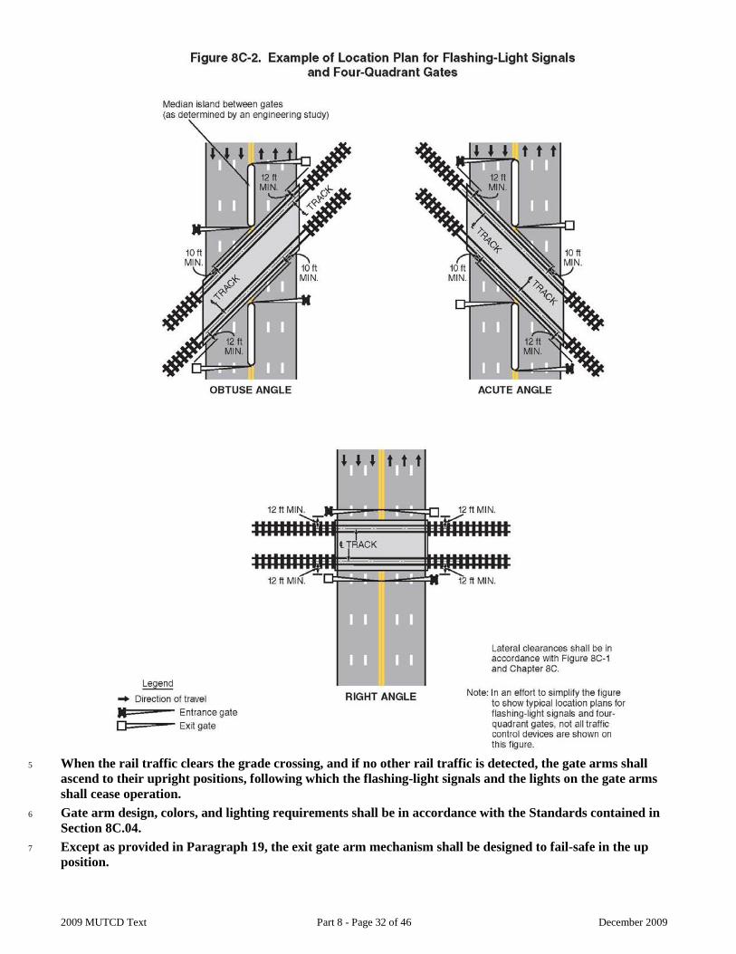
2009 MUTCD Text Part 8 - Page 32 of 46 December 2009
5 When the rail traffic clears the grade crossing, and if no other rail traffic is detected, the gate arms shall
ascend to their upright positions, following which the flashing-light signals and the lights on the gate arms shall cease operation.
6 Gate arm design, colors, and lighting requirements shall be in accordance with the Standards contained in Section 8C.04.
7 Except as provided in Paragraph 19, the exit gate arm mechanism shall be designed to fail-safe in the up position.
2009 MUTCD Text Part 8 - Page 33 of 46 December 2009
8 At locations where gate arms are offset a sufficient distance for highway vehicles to drive between the entrance and exit gate arms, median islands (see Figure 8C-2) shall be installed in accordance with the needs established by an engineering study. Guidance:
9 The gate arm should ascend to its upright position in 12 seconds or less. 10 Four-Quadrant Gate systems should only be used in locations with constant warning time detection. 11 The operating mode of the exit gates should be determined based upon an engineering study, with input from the
affected railroad company or LRT agency. 12 If the Timed Exit Gate Operating Mode is used, the engineering study, with input from the affected railroad company
or LRT agency, should also determine the Exit Gate Clearance Time (see definition in Section 1A.13). 13 If the Dynamic Exit Gate Operating Mode is used, highway vehicle intrusion detection devices that are part of a
system that incorporates processing logic to detect the presence of highway vehicles within the minimum track clearance distance should be installed to control exit gate operation.
14 Regardless of which exit gate operating mode is used, the Exit Gate Clearance Time should be considered when determining additional time requirements for the Minimum Warning Time.
15 If a Four-Quadrant Gate system is used at a location that is adjacent to an intersection that could cause highway vehicles to queue within the minimum track clearance distance, the Dynamic Exit Gate Operating Mode should be used unless an engineering study indicates otherwise.
16 If a Four-Quadrant Gate system is interconnected with a highway traffic signal, backup or standby power should be considered for the highway traffic signal. Also, circuitry should be installed to prevent the highway traffic signal from leaving the track clearance green interval until all of the gates are lowered.
17 At locations where sufficient space is available, exit gates should be positioned downstream from the track a distance that provides a safety zone long enough to accommodate at least one design vehicle between the exit gate and the nearest rail.
18 Four-Quadrant Gate systems should include remote health (status) monitoring capable of automatically notifying railroad or LRT signal maintenance personnel when anomalies have occurred within the system. Option:
19 Exit gate arms may fail in the down position if the grade crossing is equipped with remote health (status) monitoring. 20 Four-Quadrant Gate installations may include median islands between opposing lanes on an approach to a grade
crossing. Guidance:
21 Where sufficient space is available, median islands should be at least 60 feet in length.
Section 8C.07 Wayside Horn Systems Option:
1 A wayside horn system (see definition in Section 1A.13) may be installed in compliance with 49 CFR Part 222 to provide audible warning directed toward the road users at a highway-rail or highway-LRT grade crossing or at a pathway grade crossing. Standard:
2 Wayside horn systems used at grade crossings where the locomotive horn is not sounded shall be equipped and shall operate in compliance with the requirements of Appendix E to 49 CFR Part 222. Guidance:
3 The same lateral clearance and roadside safety features should apply to wayside horn systems as described in the Standards contained in Section 8C.01. Wayside horn systems, when mounted on a separate pole assembly, should be installed no closer than 15 feet from the center of the nearest track and should be positioned to not obstruct the motorists’ line of sight of the flashing-light signals.
Section 8C.08 Rail Traffic Detection Standard:
1 The devices employed in active traffic control systems shall be actuated by some form of rail traffic detection. 2 Rail traffic detection circuits, insofar as practical, shall be designed on the fail-safe principle.
2009 MUTCD Text Part 8 - Page 34 of 46 December 2009
3 Flashing-light signals shall operate for at least 20 seconds before the arrival of any rail traffic, except as provided in Paragraph 4. Option:
4 On tracks where all rail traffic operates at less than 20 mph and where road users are directed by an authorized person on the ground to not enter the crossing at all times that approaching rail traffic is about to occupy the crossing, a shorter signal operating time for the flashing-light signals may be used.
5 Additional warning time may be provided when determined by an engineering study. Guidance:
6 Where the speeds of different rail traffic on a given track vary considerably under normal operation, special devices or circuits should be installed to provide reasonably uniform notice in advance of all rail traffic movements over the grade crossing. Special control features should be used to eliminate the effects of station stops and switching operations within approach control circuits to prevent excessive activation of the traffic control devices while rail traffic is stopped on or switching upon the approach track control circuits.
Section 8C.09 Traffic Control Signals at or Near Highway-Rail Grade Crossings Option:
1 Traffic control signals may be used instead of flashing-light signals to control road users at industrial highway-rail grade crossings and other places where train movements are very slow, such as in switching operations. Standard:
2 The appropriate provisions of Part 4 relating to traffic control signal design, installation, and operation shall be applicable where traffic control signals are used to control road users instead of flashing-light signals at highway-rail grade crossings.
3 Traffic control signals shall not be used instead of flashing-light signals to control road users at a mainline highway-rail grade crossing. Guidance:
4 If a highway-rail grade crossing is equipped with a flashing-light signal system and is located within 200 feet of an intersection or midblock location controlled by a traffic control signal, the traffic control signal should be provided with preemption in accordance with Section 4D.27.
5 Coordination with the flashing-light signal system, queue detection, or other alternatives should be considered for traffic control signals located farther than 200 feet from the highway-rail grade crossing. Factors to be considered should include traffic volumes, highway vehicle mix, highway vehicle and train approach speeds, frequency of trains, and queue lengths.
6 The highway agency or authority with jurisdiction and the regulatory agency with statutory authority, if applicable, should jointly determine the preemption operation and the timing of traffic control signals interconnected with highway-rail grade crossings adjacent to signalized highway intersections. Support:
7 Section 4D.27 includes a recommendation that traffic control signals that are adjacent to highway-rail grade crossings and that are coordinated with the flashing-light signals or that include railroad preemption features be provided with a back-up power supply. Standard:
8 Information regarding the type of preemption and any related timing parameters shall be provided to the railroad company so that they can design the appropriate train detection circuitry.
9 If preemption is provided, the normal sequence of traffic control signal indications shall be preempted upon the approach of trains to avoid entrapment of highway vehicles on the highway-rail grade crossing.
10 This preemption feature shall have an electrical circuit of the closed-circuit principle, or a supervised communication circuit between the control circuits of the highway-rail grade crossing warning system and the traffic control signal controller. The traffic control signal controller preemptor shall be activated via the supervised communication circuit or the electrical circuit that is normally energized by the control circuits of the highway-rail grade crossing warning system. The approach of a train to a highway-rail grade crossing shall de-energize the electrical circuit or activate the supervised communication circuit, which in turn shall activate the traffic control signal controller preemptor. This shall establish and maintain the preemption condition during the time the highway-rail grade crossing warning system is activated, except that when
2009 MUTCD Text Part 8 - Page 35 of 46 December 2009
crossing gates exist, the preemption condition shall be maintained until the crossing gates are energized to start their upward movement. When multiple or successive preemptions occur, train activation shall receive first priority. Guidance:
11 If a highway-rail grade crossing is located within 50 feet (or within 75 feet for a highway that is regularly used by multi-unit highway vehicles) of an intersection controlled by a traffic control signal, the use of pre-signals or near side signals upstream of the grade crossing to control traffic approaching the grade crossing should be considered. Standard:
12 If used, the pre-signals shall display a steady red signal indication during the track clearance portion of a signal preemption sequence to prohibit additional highway vehicles from crossing the railroad track. Guidance:
13 Consideration should be given to using visibility-limited signal faces (see definition in Section 1A.13) at the intersection for the downstream signal faces that control the approach that is equipped with pre-signals. Option:
14 The pre-signal phase sequencing may be timed with an offset from the downstream signalized intersection such that the railroad track area and the area between the railroad track and the downstream signalized intersection is generally kept clear of stopped highway vehicles. Standard:
15 If a pre-signal or the near side sign upstream of the grade crossing is installed at an interconnected highway-rail grade crossing near a signalized intersection, a STOP HERE ON RED (R10-6) sign shall be installed near the pre-signal, near the near side signal or at the stop line if used. If there is a nearby signalized intersection with insufficient clear storage distance for a design vehicle, or the highway-rail grade crossing does not have gates, a No Turn on Red (R10-11, R10-11a, or R10-11b) sign (see Section 2B.53) shall be installed for the approach that crosses the railroad track, if applicable. Option:
16 At locations where a highway-rail grade crossing is located more than 50 feet (or more than 75 feet for a highway regularly used by multi-unit highway vehicles) from an intersection controlled by a traffic control signal, a pre-signal may be used if an engineering study determines a need.
17 If highway traffic signals must be located within close proximity to the flashing-light signal system, the highway traffic signals may be mounted on the same overhead structure as the flashing-light signals. Support:
18 Section 4C.10 describes the Intersection Near a Grade Crossing signal warrant that is intended for use at a location where the proximity to the intersection of a grade crossing on an intersection approach controlled by a STOP or YIELD sign is the principal reason to consider installing a traffic control signal.
19 Section 4D.27 describes additional considerations regarding preemption of traffic control signals at or near highway-rail grade crossings. Where traffic control signals are located near a highway-rail grade crossing, supplemental pavement markings may be applied between the dynamic envelope and the nearby downstream intersection, when justified by engineering judgment.
Standard:
If used, these markings shall be 12-inch white diagonals at a 45-degree angle and a 5-foot spacing, which shall be adjusted to not interfere with any lane control markings.
Guidance:
When the supplemental pavement markings are used, the STOP HERE ON RED (R10-6) sign or Storage Space Signs (W10-11, W10-11a, W10-11b) should be used instead of the DO NOT STOP ON TRACKS Sign (R8-8 sign) referenced in Section 8B.29 of this Supplement.
Section 8C.10 Traffic Control Signals at or Near Highway-LRT Grade Crossings Support:
2009 MUTCD Text Part 8 - Page 36 of 46 December 2009
1 There are two types of traffic control signals for controlling vehicular and LRT movements at interfaces of the two modes. The first is the standard traffic control signal described in Part 4, which is the focus of this Section. The other type of signal is referred to as an LRT signal and is discussed in Section 8C.11. Standard:
2 The provisions of Part 4 and Section 8C.09 relating to traffic control signal design, installation, and operation, including interconnection with nearby automatic gates or flashing-light signals, shall be applicable as appropriate where traffic control signals are used at highway-LRT grade crossings.
3 If traffic control signals are in operation at a crossing that is used by pedestrians, bicyclists, and/or other non-motorized road users, an audible device such as a bell shall also be provided and shall be operated in conjunction with the traffic control signals. Guidance:
4 When a highway-LRT grade crossing equipped with a flashing-light signal system is located within 200 feet of an intersection or midblock location controlled by a traffic control signal, the traffic control signal should be provided with preemption in accordance with Section 4D.27.
5 Coordination with the flashing-light signal system should be considered for traffic control signals located more than 200 feet from the crossing. Factors to be considered should include traffic volumes, highway vehicle mix, highway vehicle and LRT approach speeds, frequency of LRT traffic, and queue lengths.
6 If the highway traffic signal has emergency-vehicle preemption capability, it should be coordinated with LRT operation.
7 Where LRT operates in a wide median, highway vehicles crossing the tracks and being controlled by both near and far side traffic signal faces should receive a protected left-turn green phase from the far side signal face to clear highway vehicles from the crossing when LRT equipment is approaching the crossing. Option:
8 Green indications may be provided during LRT phases for highway vehicle, pedestrian, and bicycle movements that do not conflict with LRT movements.
9 Traffic control signals may be installed in addition to four-quadrant gate systems and automatic gates at a highway-LRT crossing if the crossing occurs within a highway-highway intersection and if the traffic control signals meet the warrants described in Chapter 4C.
10 At a location other than an intersection, when LRT speeds are less than 25 mph, traffic control signals alone may be used to control road users at highway-LRT grade crossings only when justified by an engineering study.
11 Typical circumstances may include: A. Geometric conditions preclude the installation of highway-LRT grade crossing warning devices. B. LRT vehicles share the same roadway with road users. C. Traffic control signals already exist.
Support: 12 Section 4D.27 contains information regarding traffic control signals at or near highway-LRT grade crossings that are
not equipped with highway-LRT grade crossing warning devices. 13 Section 4C.10 describes the Intersection Near a Grade Crossing signal warrant that is intended for use at a location
where the proximity to the intersection of a grade crossing on an intersection approach controlled by a STOP or YIELD sign is the principal reason to consider installing a traffic control signal. Guidance:
14 When a highway-LRT grade crossing exists within a signalized intersection, consideration should be given to providing separate turn signal faces (see definition in Section 1A.13) for the movements crossing the tracks. Standard:
15 Separate turn signal faces that are provided for turn movements toward the crossing shall display a steady red indication during the approach and/or passage of LRT traffic. Guidance:
16 When a signalized intersection that is located within 200 feet of a highway-LRT grade crossing is preempted, all existing turning movements toward the highway-LRT grade crossing should be prohibited. Support:
2009 MUTCD Text Part 8 - Page 37 of 46 December 2009
17 Section 8B.08 contains information regarding the prohibition of turning movements toward the crossing during preemption.
18 Part 4 contains information regarding signal phasing and timing requirements.
Section 8C.11 Use of Traffic Control Signals for Control of LRT Vehicles at Grade Crossings Guidance:
1 LRT movements in semi-exclusive alignments at non-gated grade crossings that are equipped with traffic control signals should be controlled by special LRT signal indications.
2 LRT traffic control signals that are used to control LRT movements only should display the signal indications illustrated in Figure 8C-3. Support:
3 Section 4D.27 contains information about the use of the signal indications shown in Figure 8C-3 for the control of exclusive bus movements at “queue jumper lanes” and for the control of exclusive bus rapid transit movements on semi-exclusive or mixed-use alignments. Option:
4 Standard traffic control signals may be used instead of LRT traffic control signals to control the movement of LRT vehicles (see Section 8C.10). Standard:
5 If a separate set of standard traffic control signal indications (red, yellow, and green circular and arrow indications) is used to control LRT movements, the indications shall be positioned so they are not visible to motorists, pedestrians, and bicyclists (see Section 4D.12).
6 If the LRT crossing control is separate from the intersection control, the two shall be interconnected. The LRT signal phase shall not be terminated until after the LRT vehicle has cleared the crossing. Option:
7 LRT signals may be used at grade crossings and at intersections in mixed-use alignments in conjunction with standard traffic control signals where special LRT signal phases are used to accommodate turning LRT vehicles or where additional LRT clearance time is desirable. Guidance:
8 LRT signal faces should be separated vertically or horizontally from the nearest highway traffic signal face for the same approach by at least 3 feet.
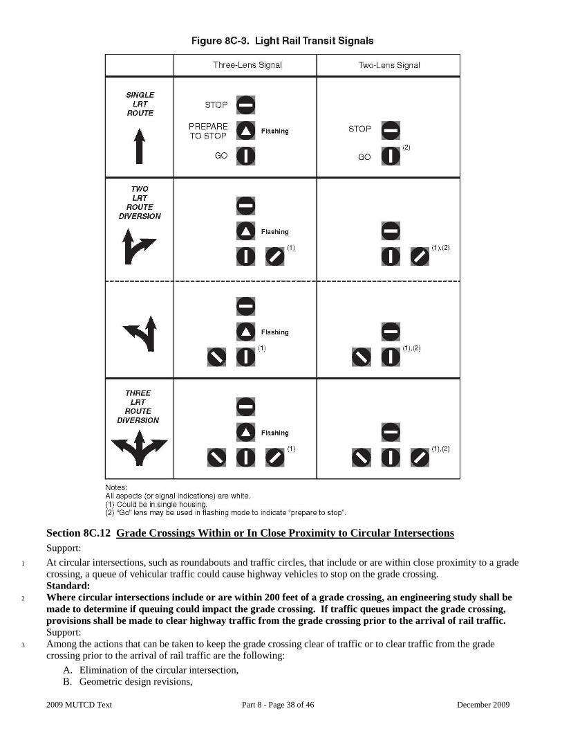
2009 MUTCD Text Part 8 - Page 38 of 46 December 2009
Section 8C.12 Grade Crossings Within or In Close Proximity to Circular Intersections Support:
1 At circular intersections, such as roundabouts and traffic circles, that include or are within close proximity to a grade crossing, a queue of vehicular traffic could cause highway vehicles to stop on the grade crossing. Standard:
2 Where circular intersections include or are within 200 feet of a grade crossing, an engineering study shall be made to determine if queuing could impact the grade crossing. If traffic queues impact the grade crossing, provisions shall be made to clear highway traffic from the grade crossing prior to the arrival of rail traffic. Support:
3 Among the actions that can be taken to keep the grade crossing clear of traffic or to clear traffic from the grade crossing prior to the arrival of rail traffic are the following:
A. Elimination of the circular intersection, B. Geometric design revisions,
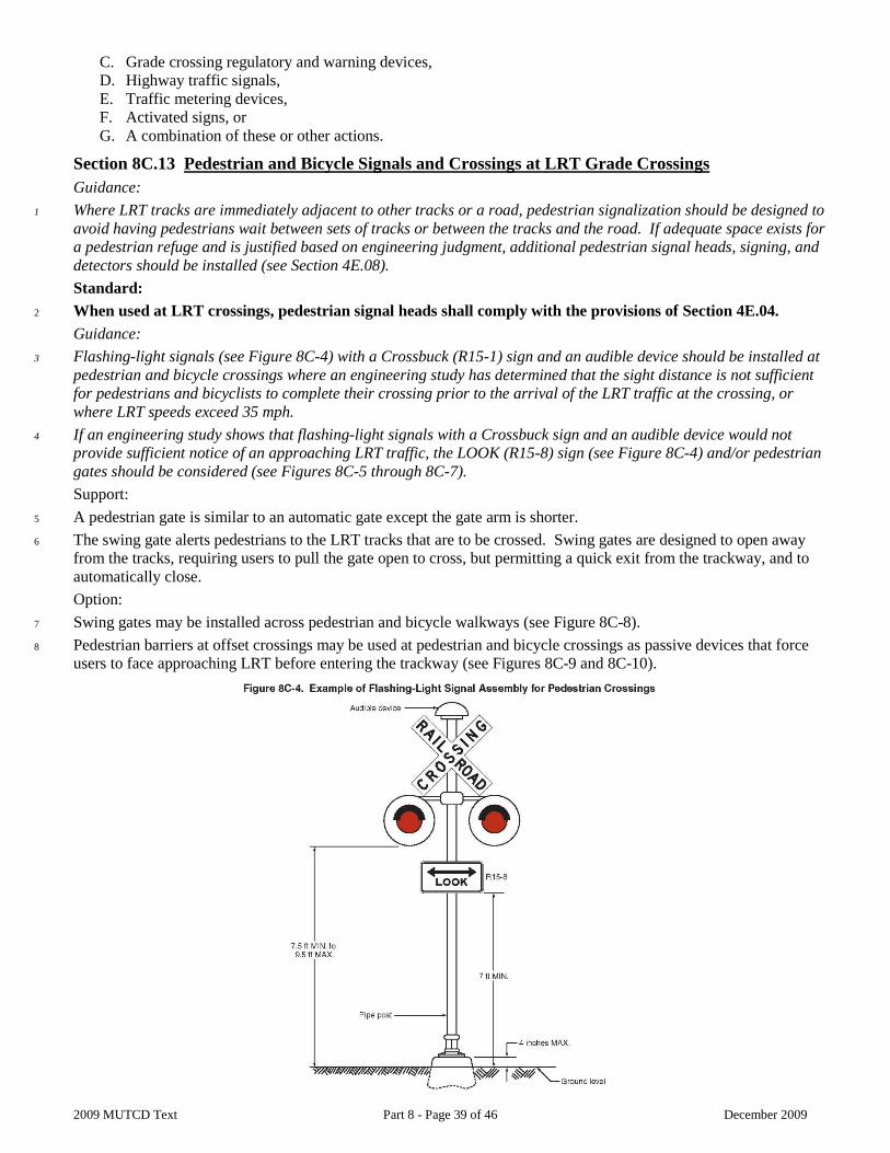
2009 MUTCD Text Part 8 - Page 39 of 46 December 2009
C. Grade crossing regulatory and warning devices, D. Highway traffic signals, E. Traffic metering devices, F. Activated signs, or G. A combination of these or other actions.
Section 8C.13 Pedestrian and Bicycle Signals and Crossings at LRT Grade Crossings Guidance:
1 Where LRT tracks are immediately adjacent to other tracks or a road, pedestrian signalization should be designed to avoid having pedestrians wait between sets of tracks or between the tracks and the road. If adequate space exists for a pedestrian refuge and is justified based on engineering judgment, additional pedestrian signal heads, signing, and detectors should be installed (see Section 4E.08). Standard:
2 When used at LRT crossings, pedestrian signal heads shall comply with the provisions of Section 4E.04. Guidance:
3 Flashing-light signals (see Figure 8C-4) with a Crossbuck (R15-1) sign and an audible device should be installed at pedestrian and bicycle crossings where an engineering study has determined that the sight distance is not sufficient for pedestrians and bicyclists to complete their crossing prior to the arrival of the LRT traffic at the crossing, or where LRT speeds exceed 35 mph.
4 If an engineering study shows that flashing-light signals with a Crossbuck sign and an audible device would not provide sufficient notice of an approaching LRT traffic, the LOOK (R15-8) sign (see Figure 8C-4) and/or pedestrian gates should be considered (see Figures 8C-5 through 8C-7). Support:
5 A pedestrian gate is similar to an automatic gate except the gate arm is shorter. 6 The swing gate alerts pedestrians to the LRT tracks that are to be crossed. Swing gates are designed to open away
from the tracks, requiring users to pull the gate open to cross, but permitting a quick exit from the trackway, and to automatically close. Option:
7 Swing gates may be installed across pedestrian and bicycle walkways (see Figure 8C-8). 8 Pedestrian barriers at offset crossings may be used at pedestrian and bicycle crossings as passive devices that force
users to face approaching LRT before entering the trackway (see Figures 8C-9 and 8C-10).
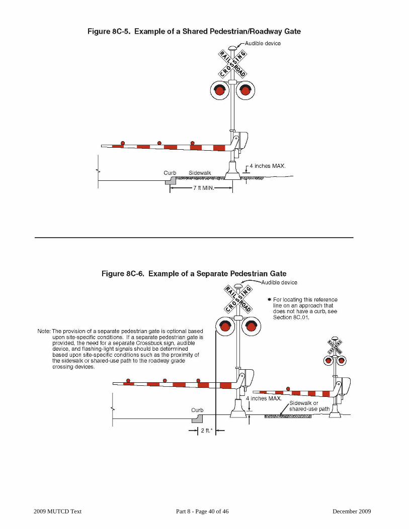
2009 MUTCD Text Part 8 - Page 40 of 46 December 2009
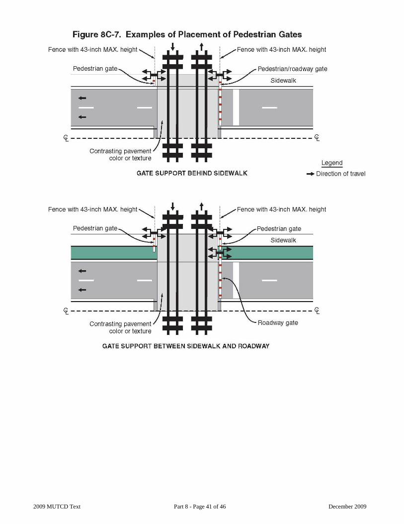
2009 MUTCD Text Part 8 - Page 41 of 46 December 2009
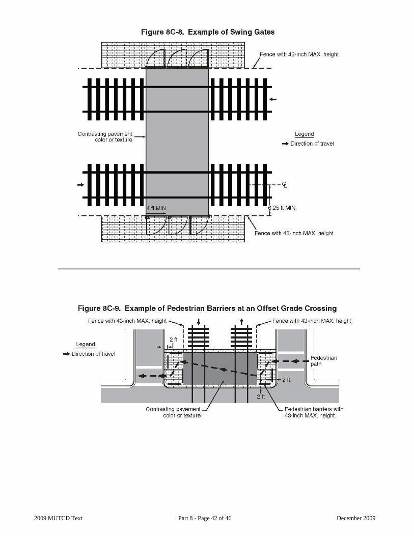
2009 MUTCD Text Part 8 - Page 42 of 46 December 2009

2009 MUTCD Text Part 8 - Page 43 of 46 December 2009

2009 MUTCD Text Part 8 - Page 44 of 46 December 2009
CHAPTER 8D. PATHWAY GRADE CROSSINGS Section 8D.01 Purpose Support:
1 Traffic control for pathway grade crossings includes all signs, signals, markings, other warning devices, and their supports at pathway grade crossings and along pathway approaches to grade crossings. The function of this traffic control is to promote safety and provide effective operation of both rail and pathway traffic at pathway grade crossings.
2 Except as specifically provided in this Chapter, sidewalks are considered to be part of a highway-rail or highway-LRT grade crossing rather than a pathway grade crossing, and are covered by the provisions of Chapters 8B and 8C rather than by the provisions of this Chapter. However, many of the treatments outlined in this Chapter are applicable to sidewalks adjacent to highway-rail or highway-LRT grade crossings, including detectable warnings, swing gates, and automatic gates.
3 Crosswalks at intersections where pedestrians cross LRT tracks in mixed-use alignments are covered by the provisions of Section 3B.18 rather than by the provisions of this Chapter.
Section 8D.02 Use of Standard Devices, Systems, and Practices Guidance:
1 The public agency with jurisdiction over the pathway and the regulatory agency with statutory authority, if applicable, should jointly determine the need and selection of devices at a pathway grade crossing, including the appropriate traffic control system to be used.
Section 8D.03 Pathway Grade Crossing Signs and Markings Standard:
1 Pathway grade crossing signs shall be standard in shape, legend, and color. 2 Traffic control devices mounted adjacent to pathways at a height of less than 8 feet measured vertically from
the bottom edge of the device to the elevation of the near edge of the pathway surface shall have a minimum lateral offset of 2 feet from the near edge of the device to the near edge of the pathway (see Figure 9B-1).
3 The minimum mounting height for post-mounted signs on pathways shall be 4 feet, measured vertically from the bottom edge of the sign to the elevation of the near edge of the pathway surface (see Figure 9B-1).
4 Pathway grade crossing traffic control devices shall be located a minimum of 12 feet from the center of the nearest track.
5 The minimum sizes of pathway grade crossing signs shall be as shown in the shared-use path column in Table 9B-1.
6 When overhead traffic control devices are used on pathways, the clearance from the bottom edge of the device to the pathway surface directly under the sign or device shall be at least 8 feet. Guidance:
7 If pathway users include those who travel faster than pedestrians, such as bicyclists or skaters, the use of warning signs and pavement markings in advance of the pathway grade crossing (see Figure 8D-1) should be considered.
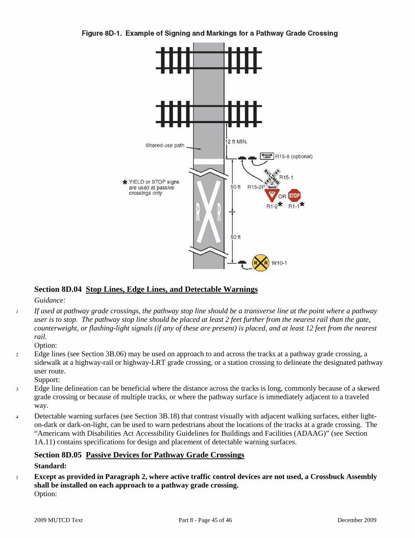
2009 MUTCD Text Part 8 - Page 45 of 46 December 2009
Section 8D.04 Stop Lines, Edge Lines, and Detectable Warnings Guidance:
1 If used at pathway grade crossings, the pathway stop line should be a transverse line at the point where a pathway user is to stop. The pathway stop line should be placed at least 2 feet further from the nearest rail than the gate, counterweight, or flashing-light signals (if any of these are present) is placed, and at least 12 feet from the nearest rail. Option:
2 Edge lines (see Section 3B.06) may be used on approach to and across the tracks at a pathway grade crossing, a sidewalk at a highway-rail or highway-LRT grade crossing, or a station crossing to delineate the designated pathway user route. Support:
3 Edge line delineation can be beneficial where the distance across the tracks is long, commonly because of a skewed grade crossing or because of multiple tracks, or where the pathway surface is immediately adjacent to a traveled way.
4 Detectable warning surfaces (see Section 3B.18) that contrast visually with adjacent walking surfaces, either light-on-dark or dark-on-light, can be used to warn pedestrians about the locations of the tracks at a grade crossing. The “Americans with Disabilities Act Accessibility Guidelines for Buildings and Facilities (ADAAG)” (see Section 1A.11) contains specifications for design and placement of detectable warning surfaces.
Section 8D.05 Passive Devices for Pathway Grade Crossings Standard:
1 Except as provided in Paragraph 2, where active traffic control devices are not used, a Crossbuck Assembly shall be installed on each approach to a pathway grade crossing. Option:
2009 MUTCD Text Part 8 - Page 46 of 46 December 2009
2 The Crossbuck Assembly may be omitted at station crossings and on the approaches to a pathway grade crossing that is located within 25 feet of the traveled way at a highway-rail or highway-LRT grade crossing. Guidance:
3 The pathway user’s ability to detect the presence of approaching rail traffic should be considered in determining the type and placement of traffic control devices or design features (such as fencing or swing gates).
4 Nighttime visibility should be considered if design features (such as fencing or swing gates) are used to channelize pathway users.
5 If automatic gates and swing gates are used, the pathway should be channelized to direct users to the entrance to and exit from the pathway grade crossing. Standard:
6 If used, swing gates shall be designed to open away from the track(s) so that pathway users can quickly push the gate open when moving away from the track(s). If used, swing gates shall be designed to automatically return to the closed position after each use. Option:
7 When used in conjunction with automatic gates at pathway grade crossings, swing gates may be equipped with a latching device that permits the gate to be opened only from the track side of the gate. Support:
8 The “Americans with Disabilities Act Accessibility Guidelines for Buildings and Facilities (ADAAG)” (see Section 1A.11) contains information regarding spring hinges and door and gate opening forces for swing gates.
Section 8D.06 Active Traffic Control Systems for Pathway Grade Crossings Standard:
1 If used at a pathway grade crossing, an active traffic control system shall include flashing-light signals for each direction of the pathway. A bell or other audible warning device shall also be provided. Option:
2 Separate active traffic control devices may be omitted at a pathway grade crossing that is located within 25 feet of the traveled way of a highway-rail or highway-LRT grade crossing that is equipped with an active traffic control system. Standard:
3 If used at pathway grade crossings, alternately flashing red lights shall be aligned horizontally and the light units shall have a diameter of at least 4 inches. The minimum mounting height of the flashing red lights shall be 4 feet, measured vertically from the bottom edge of the lights to the elevation of the near edge of the pathway surface. Option:
4 Traffic control devices may be installed between the tracks at multiple track crossings at stations. Standard:
5 The mounting height for flashing lights that are installed between the tracks at multiple track crossings at stations shall be a minimum of 1 foot, measured vertically from the bottom edge of the lights to the elevation of the near edge of the pathway surface. Option:
6 Automatic gates may be used at pathway grade crossings. Guidance:
7 If used at a pathway grade crossing, the height of the automatic gate arm when in the down position should be a minimum of 2.5 feet and a maximum of 4 feet above the sidewalk.
8 If used, the gate configuration, which might include a combination of automatic gates and swing gates, should provide for full width coverage of the pathway on both approaches to the track. Standard:
9 Where a sidewalk is located between the edge of a roadway and the support for a gate arm that extends across the sidewalk and into the roadway, the location, placement, and height prescribed for vehicular gates shall be used (see Section 8C.04). Guidance:
10 If a separate automatic gate is used for a sidewalk, the height of the gate arm when in the down position should be a minimum of 2.5 feet and a maximum of 4 feet above the sidewalk.
11 If a separate automatic gate is used for a sidewalk at a highway-rail or highway-LRT grade crossing, instead of a supplemental or auxiliary gate arm installed as a part of the same mechanism as the vehicular gate, a separate mechanism should be provided for the sidewalk gate to prevent a pedestrian from raising the vehicular gate.