
Part 8-Chap 1 Electrical and Electronic Services
76
Part 8 Building Services 8‐1 Chapter 1 Electrical and Electronic Engineering Services for Buildings 1.1 Introduction 1.1.1 Aim of this section of Codes of Electrical and Electronic Engineering Installations in Buildings The aim of the codes for Electrical and Electronic Engineering Services for Buildings presented in this section is to ensure that the related installation work becomes perfect safe for the persons residing in and around the building. The term safe means safe for the persons and safe for the properties. The codes in this section have been presented to set minimum standards for Electrical and Electronic Engineering Installations in Residential Buildings, Multistoried Apartment Buildings, Commercial Buildings, Office Buildings, Rail Stations, Airport Buildings, Factory Buildings, Warehouses, Jetties, Container Yards, Other Yards, Parking lots and similar places. All the systems and equipment intended for the supply of normal power and standby power to all these places are covered by these codes. Electrical and Electronic Engineering Installations include Lighting and Illumination, Fans Cooling/Heating system, Normal and Standby power supply system, Supply system for the Lifts, Telecommunications Systems, Data Communication Systems, Fire Alarm System, CCTV monitoring System, Cable Television Distribution System, Electronic Access Control System, Burglar Alarm System. Electrical wiring / cabling form a major part in the above mentioned installation works. Electrical wiring / cabling must be reasonably safe to persons and property. Installations, alteration, or extension of Electrical wiring / cabling systems conforming to the provisions of this code shall be deemed to be reasonably safe to persons and property. 1.1.2 Guiding Sources of the Codes of Electrical and Electronic Engineering Installations Significant Modification, Upgradation and Additions of the Previous Electrical Engineering Section of BNBC of 1993 have been incorporated in this updated version. While making changes and additions, the following documents/ regulations/ codes have been taken as reference/ guiding sources: a) Bangladesh Electricity Act. b) IEE wiring Regulation (17th edition) BS: 7671 2008 including all parts. c) British Standards (BS). In addition to these, the following documents/ regulations/ codes have also been taken as references as required: a) National Building code of India – 2005. b) Building code of Pakistan – latest version. c) National Electrical Code of USA with necessary modifications for Bangladesh. d) International Electrotechnical Commission (IEC) standards for International Standards for all electrical, electronic and related technologies as applicable to Bangladesh. e) ISO 50001 standard for Energy management System. f) International Electrotechnical Commission (IEC) specifies the standards related to energy production and distribution, electronics, magnetics and electromagnetics, electroacoustics, multimedia and telecommunication, as well as associated general disciplines such as terminology and symbols, electromagnetic compatibility, measurement and performance, dependability, design and development, safety and the environment.
description
Bangladesh National Building Code
Transcript of Part 8-Chap 1 Electrical and Electronic Services

Part 8 Building Services 8‐1
Chapter 1
Electrical and Electronic Engineering Services for Buildings
1.1 Introduction
1.1.1 Aim of this section of Codes of Electrical and Electronic Engineering Installations in Buildings
The aim of the codes for Electrical and Electronic Engineering Services for Buildings presented in this section is to ensure that the related installation work becomes perfect safe for the persons residing in and around the building. The term safe means safe for the persons and safe for the properties.
The codes in this section have been presented to set minimum standards for Electrical and Electronic Engineering Installations in Residential Buildings, Multistoried Apartment Buildings, Commercial Buildings, Office Buildings, Rail Stations, Airport Buildings, Factory Buildings, Warehouses, Jetties, Container Yards, Other Yards, Parking lots and similar places. All the systems and equipment intended for the supply of normal power and standby power to all these places are covered by these codes. Electrical and Electronic Engineering Installations include Lighting and Illumination, Fans Cooling/Heating system, Normal and Standby power supply system, Supply system for the Lifts, Telecommunications Systems, Data Communication Systems, Fire Alarm System, CCTV monitoring System, Cable Television Distribution System, Electronic Access Control System, Burglar Alarm System.
Electrical wiring / cabling form a major part in the above mentioned installation works. Electrical wiring / cabling must be reasonably safe to persons and property. Installations, alteration, or extension of Electrical wiring / cabling systems conforming to the provisions of this code shall be deemed to be reasonably safe to persons and property.
1.1.2 Guiding Sources of the Codes of Electrical and Electronic Engineering Installations
Significant Modification, Upgradation and Additions of the Previous Electrical Engineering Section of BNBC of 1993 have been incorporated in this updated version.
While making changes and additions, the following documents/ regulations/ codes have been taken as reference/ guiding sources:
a) Bangladesh Electricity Act.
b) IEE wiring Regulation (17th edition) BS: 7671 2008 including all parts.
c) British Standards (BS).
In addition to these, the following documents/ regulations/ codes have also been taken as references as required:
a) National Building code of India – 2005.
b) Building code of Pakistan – latest version.
c) National Electrical Code of USA with necessary modifications for Bangladesh.
d) International Electrotechnical Commission (IEC) standards for International Standards for all electrical, electronic and related technologies as applicable to Bangladesh.
e) ISO 50001 standard for Energy management System.
f) International Electrotechnical Commission (IEC) specifies the standards related to energy production and distribution, electronics, magnetics and electromagnetics, electroacoustics, multimedia and telecommunication, as well as associated general disciplines such as terminology and symbols, electromagnetic compatibility, measurement and performance, dependability, design and development, safety and the environment.

Part 8 Building Services
8‐2 Vol. 3
g) Verband Deutscher Elektrotechniker (Association of German Electrical Engineers) (VDE).
However, efforts have been be given to accept a significant part of rules and practices mentioned in IEE wiring Regulation (17th edition) BS: 7671 2008 including all parts with necessary modifications for our system and suitable for our country. While preparing this document the following standards and practices are kept in mind.
a) For having safe domestic electrical systems, domestic electrical installations shall be designed and installed according to the "fundamental principles" given in British Standard BS 7671 Chapter 13. These are similar to the fundamental principles defined in international standard IEC 60364‐1. It is necessary to apply British Standard BS 7671 (the "Wiring Regulations"), including carrying out adequate inspection and testing to this standard of the completed works.
i. To meet the above mentioned requirements the following rules and guidance shall be followed.
ii. The rules of the IEE wiring regulations (BS 7671), colloquially referred to as "the regs" (BS 7671: 2008, 17th Edition).;
iii. The rules of an equivalent standard approved by a member of the European Economic Area (e.g., DIN/VDE 0100);
b) Guidance given in installation manuals that are consistent with BS 7671, such as the IEE On‐Site Guide and IEE Guidance Notes Nos 1 to 7.
c) Installations in commercial and industrial premises must satisfy the requirements set in Electricity at Work Regulations 1989 (UK) and must follow recognised standards and practices, such as BS 7671 "Wiring Regulations".
Apart from these, some modifications had to be made considering the weather and other local conditions, practices and previous experiences in this country.
1.1.3 Designing an Electrical and Electronic Engineering Installations in Buildings and related structures
The codes presented in this section are not meant to provide adequate information to design Electrical and Electronic Engineering Installations and Systems in Buildings and related structures. These should not be taken to be adequate or complete for the efficient design work of installations.
Such design work, the required features, detailed technical specifications, schedule of items etc., should be obtained through the services of an engineer adequately qualified in this area. Energy efficient appliances should be considered during electrical designing.
1.2 Lighting and Illumination
1.2.1 Determination of Illumination Levels for Different Application (Principle of Lighting )
The essential features of an efficient lighting system are:
a) visual comfort through adequate illumination of the working surface,
b) prevention of glare,
c) avoidance of shadows, and
d) ease of maintenance.
The design of a lighting system shall involve:
a) careful planning of the brightness and colour pattern within both the working areas and the surroundings so that attention is drawn naturally to the important areas, so that details can be seen quickly and accurately, and so that the appearance inside the room is free from any sense monotony,
b) use of directional lighting to assist perception of task detail,
c) controlling direct and reflected glare from light sources to eliminate visual discomfort,
d) minimizing flicker from certain types of lamps and paying attention to the colour rendering properties of the light,
Electrical and Electronic Engineering Services for Buildings Chapter 1
Bangladesh National Building Code 2011 8‐3
e) the correlation of lighting throughout the building to prevent excessive differences between adjacent areas, so as to reduce the risk of accidents, and
f) the installation of emergency lighting systems, wherever necessary.
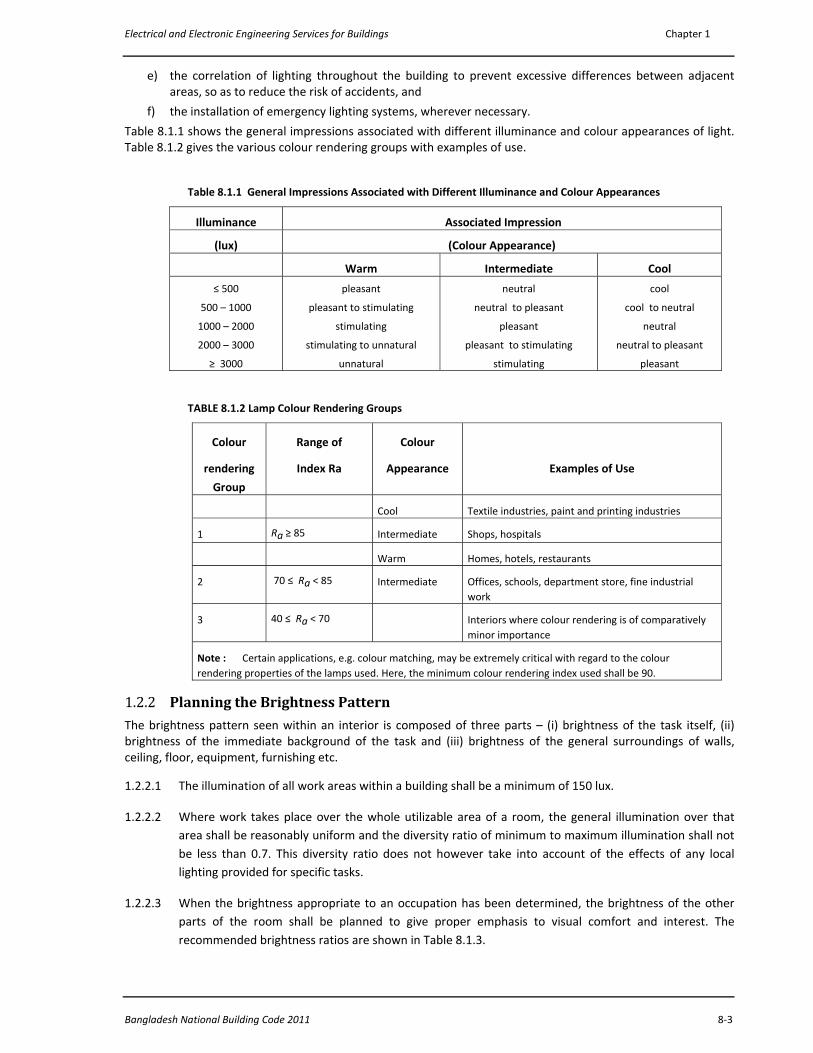
Table 8.1.1 shows the general impressions associated with different illuminance and colour appearances of light. Table 8.1.2 gives the various colour rendering groups with examples of use.
Table 8.1.1 General Impressions Associated with Different Illuminance and Colour Appearances
Illuminance Associated Impression
(lux) (Colour Appearance)
Warm Intermediate Cool
≤ 500
500 – 1000
1000 – 2000
2000 – 3000
≥ 3000
pleasant
pleasant to stimulating
stimulating
stimulating to unnatural
unnatural
neutral
neutral to pleasant
pleasant
pleasant to stimulating
stimulating
cool
cool to neutral
neutral
neutral to pleasant
pleasant
TABLE 8.1.2 Lamp Colour Rendering Groups
Colour
rendering
Group
Range of
Index Ra
Colour
Appearance
Examples of Use
Cool Textile industries, paint and printing industries
1 Ra ≥ 85 Intermediate Shops, hospitals
Warm Homes, hotels, restaurants
2 70 ≤ Ra < 85 Intermediate Offices, schools, department store, fine industrial work
3 40 ≤ Ra < 70 Interiors where colour rendering is of comparatively minor importance
Note : Certain applications, e.g. colour matching, may be extremely critical with regard to the colour rendering properties of the lamps used. Here, the minimum colour rendering index used shall be 90.
1.2.2 Planning the Brightness Pattern
The brightness pattern seen within an interior is composed of three parts – (i) brightness of the task itself, (ii) brightness of the immediate background of the task and (iii) brightness of the general surroundings of walls, ceiling, floor, equipment, furnishing etc.
1.2.2.1 The illumination of all work areas within a building shall be a minimum of 150 lux.
1.2.2.2 Where work takes place over the whole utilizable area of a room, the general illumination over that area shall be reasonably uniform and the diversity ratio of minimum to maximum illumination shall not be less than 0.7. This diversity ratio does not however take into account of the effects of any local lighting provided for specific tasks.
1.2.2.3 When the brightness appropriate to an occupation has been determined, the brightness of the other parts of the room shall be planned to give proper emphasis to visual comfort and interest. The recommended brightness ratios are shown in Table 8.1.3.

Part 8 Building Services
8‐4 Vol. 3
1.2.3 Lighting Calculations
1.2.3.1 In order to determine the necessary number of lamps and luminaires for a specified illumination level or the average illuminance obtained from a particular lighting design, the Lumen Method of calculation shall be employed.
1.2.3.2 Unless the reflection factors are known to the lighting designer, the triplet 0.7/0.5/0.3 for the reflectances of ceiling, walls and working plane respectively shall be used for offices and the triplet 0.7/0.5/0.1 for other premises. Typical reflection factors of smooth coloured surfaces are given in Table 8.1.4.
Table 8.1.3 Brightness Ratios Between Task, Adjacent Sources and Surroundings
For high task brightness (above 100 cd/m2) :
Maximum ratio between task brightness and the adjacent
sources like table tops
3 to 1
Maximum ratio between task brightness and illumination of
the remote areas of the room not being used as work areas
10 to 1
For low and medium task brightness (below 100 cd/m2) The task must be brighter than both the
background and the surroundings; the lower the
task brightness, the less critical is the
relationship.
Table 8.1.4 Reflection Factors of Smooth Coloured Surfaces
Colour Reflection Factor Colour Reflection Factor
Flat white
Ivory
Buff
Yellow
Light tan
0.75 – 0.85
0.70 – 0.75
0.60 – 0.70
0.55 – 0.65
0.45 – 0.55
Light green
Grey
Blue
Red
Dark brown
0.40 – 0.50
0.30 – 0.50
0.25 – 0.35
0.15 – 0.20
0.10 – 0.15
1.2.4 Recommended Illumination Values
The recommended values of illumination required for buildings of different occupancies, based on activity, are given in Tables 1.5 through 1.11. The initial illuminance should be higher than the recommended value to allow for the fact that the illuminance will inevitably drop below this value by the end of the cleaning and replacing period.
A gradual transition (rather than a sudden change) of brightness from one portion to another within the field of vision is recommended so as to avoid or minimize glare discomfort.
1.2.5 Artificial Lighting to Supplement Daylight
Supplementary lighting shall be used when illumination from daylight falls below 150 lux on the working plane.
For providing supplementary artificial lighting when daylight availability becomes insufficient, cool daylight fluorescent tubes with semi‐direct luminaires are recommended. To ensure a good distribution of illumination, the mounting height should be between 1.5 and 2.0 m above the work plane with a separation of 2.0 to 3.0 m between the luminaires.
1.2.6 Selection of Appropriate Light Fittings
1.2.6.1 Light Fitting
An electric lamp and its fitting accessories, reflector, diffuser, mounting brackets, suspenders etc., shall be regarded as one unit; they shall be designed to match each other and to give the desired distribution of light. Any
Electrical and Electronic Engineering Services for Buildings Chapter 1
Bangladesh National Building Code 2011 8‐5
focusing fittings used which enable the light distribution to be varied by adjustment of the lamp position shall also be designed for the type and size of lamp to be used.
1.2.6.2 Classification of Light Fittings
Light fittings shall be classified into five categories according to the proportion of the total light output in the lower hemisphere. These are:
a) Direct fittings, giving 90‐100 percent light downwards;
b) Semi‐direct fittings, giving 60‐90 percent downwards;
c) General diffusing fittings, giving 40‐60 percent light downwards;
d) Semi‐indirect fittings, giving 10‐40 per cent light downwards;
e) Indirect fittings, giving 0‐10 per cent light downwards.
1.2.6.2.1 Direct fittings Direct fittings shall be used in situations where efficiency of illumination is the major criterion, while contract of the light source with the surroundings, shadows, and direct/reflected glare may be considered to be of relatively minor importance.
1.2.6.2.2 Semidirect fittings Semidirect fittings shall be used in areas where it felt that the reduction of contrast resulting from the small indirect component of light directed towards the ceiling shall be sufficient for the purpose.
1.2.6.2.3 General diffusing fittings General diffusing fittings shall be used where, in addition to a substantial indirect component of light aiding materially to the diffused character of the general illumination, an upward component providing a brighter background against which to view the luminance, especially for interiors with light‐coloured ceiling and walls, is desirable.
1.2.6.2.4 Semi‐indirect fittings Semi‐indirect fittings shall be used when a comfortable brightness ratio between the ceiling and the luminaire is desirable but an efficiency of illumination, higher than that obtainable from indirect fittings is required.
1.2.6.2.5 Indirect fittings Indirect fittings shall be used in situations where an environment of evenly distributed illumination is to be achieved, efficiency of illumination not being a dominant factor.
1.2.6.2.6 Angle Lighting For good lighting on vertical surfaces, avoiding shadows, creating shadows using concentrated source of lighting for interior or exterior lighting
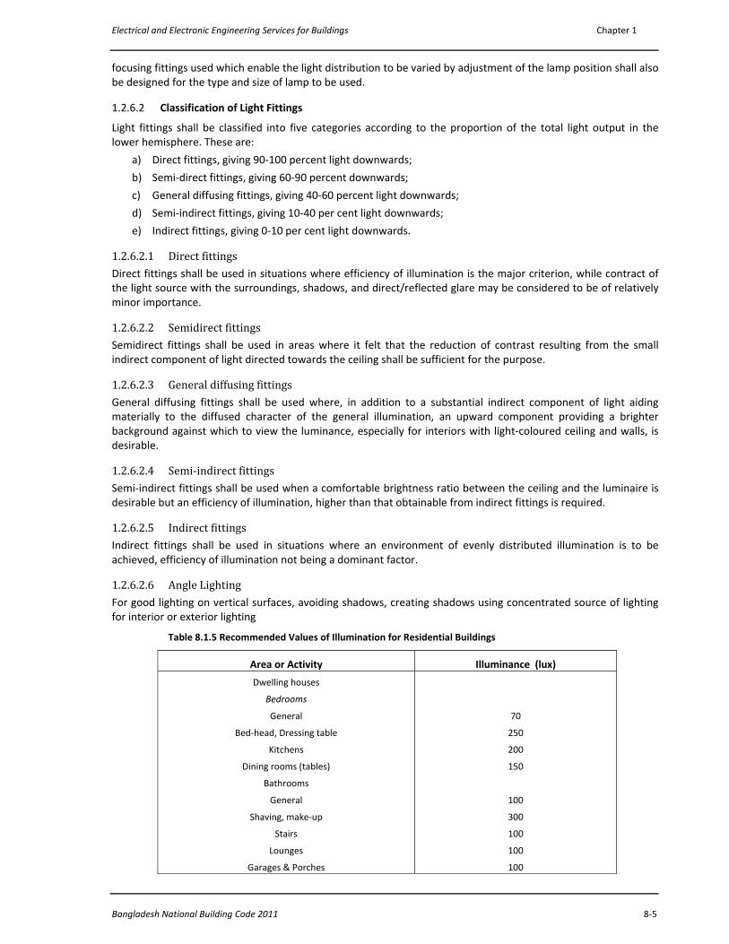
Table 8.1.5 Recommended Values of Illumination for Residential Buildings
Area or Activity Illuminance (lux)
Dwelling houses
Bedrooms
General
Bed‐head, Dressing table
Kitchens
Dining rooms (tables)
Bathrooms
General
Shaving, make‐up
Stairs
Lounges
Garages & Porches
70
250
200
150
100
300
100
100
100
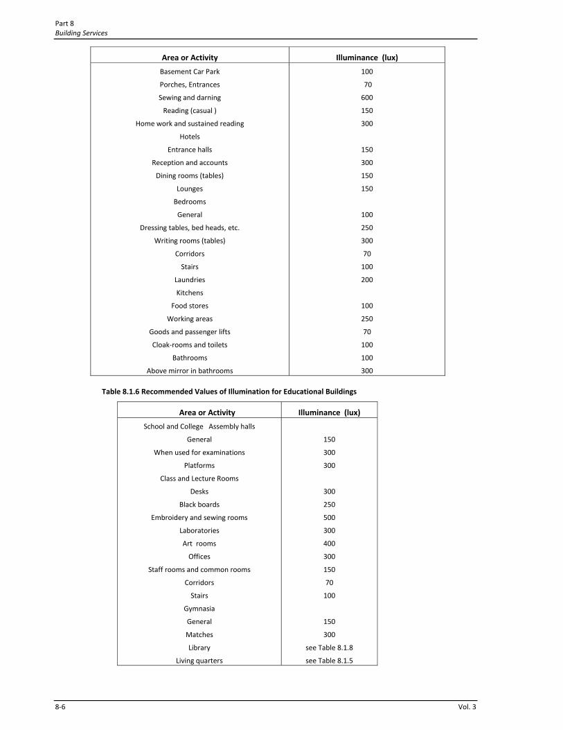
Part 8 Building Services
8‐6 Vol. 3
Area or Activity Illuminance (lux)
Basement Car Park
Porches, Entrances
Sewing and darning
Reading (casual )
Home work and sustained reading
Hotels
Entrance halls
Reception and accounts
Dining rooms (tables)
Lounges
Bedrooms
General
Dressing tables, bed heads, etc.
Writing rooms (tables)
Corridors
Stairs
Laundries
Kitchens
Food stores
Working areas
Goods and passenger lifts
Cloak‐rooms and toilets
Bathrooms
Above mirror in bathrooms
100
70
600
150
300
150
300
150
150
100
250
300
70
100
200
100
250
70
100
100
300
Table 8.1.6 Recommended Values of Illumination for Educational Buildings
Area or Activity Illuminance (lux)
School and College Assembly halls
General
When used for examinations
Platforms
Class and Lecture Rooms
Desks
Black boards
Embroidery and sewing rooms
Laboratories
Art rooms
Offices
Staff rooms and common rooms
Corridors
Stairs
Gymnasia
General
Matches
Library
Living quarters
150
300
300
300
250
500
300
400
300
150
70
100
150
300
see Table 8.1.8
see Table 8.1.5
Electrical and Electronic Engineering Services for Buildings Chapter 1
Bangladesh National Building Code 2011 8‐7
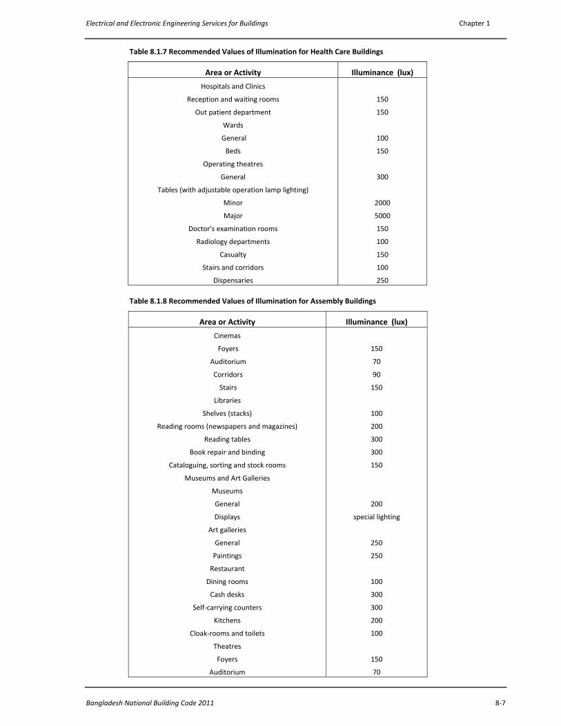
Table 8.1.7 Recommended Values of Illumination for Health Care Buildings
Area or Activity Illuminance (lux)
Hospitals and Clinics
Reception and waiting rooms
Out patient department
Wards
General
Beds
Operating theatres
General
Tables (with adjustable operation lamp lighting)
Minor
Major
Doctor's examination rooms
Radiology departments
Casualty
Stairs and corridors
Dispensaries
150
150
100
150
300
2000
5000
150
100
150
100
250
Table 8.1.8 Recommended Values of Illumination for Assembly Buildings
Area or Activity Illuminance (lux)
Cinemas
Foyers
Auditorium
Corridors
Stairs
Libraries
Shelves (stacks)
Reading rooms (newspapers and magazines)
Reading tables
Book repair and binding
Cataloguing, sorting and stock rooms
Museums and Art Galleries
Museums
General
Displays
Art galleries
General
Paintings
Restaurant
Dining rooms
Cash desks
Self‐carrying counters
Kitchens
Cloak‐rooms and toilets
Theatres
Foyers
Auditorium
150
70
90
150
100
200
300
300
150
200
special lighting
250
250
100
300
300
200
100
150
70

Part 8 Building Services
8‐8 Vol. 3
Area or Activity Illuminance (lux)
Corridors
Stairs
Indoor Sports Centre
Halls
Swimming pools
Lawn or table tennis, badminton, volley ball
Tournament
Club
Recreational
Shooting ranges
On target
Firing point
Range
Football
90
150
200
250
300
200
150
300
200
100
500
TABLE 8.1.9 Recommended Values of Illumination for Business and Commercial Buildings
Area or Activity Illuminance (lux)
Airport Building
Reception areas (desks)
Baggage, customs and immigration halls
Circulation areas, lounges
Banks
Counter, typing and accounting book areas
Public areas, lobby
Offices
Book binding
Pasting, punching and stitching
Binding and folding and miscellaneous machines
Finishing, blocking and inlaying
Dental Surgeries
Waiting rooms
Surgeries
General
Chairs
Laboratories
Doctor's Surgeries
Waiting rooms and consulting rooms
Corridors
Stairs
Eyesight testing (acuity) wall charts and near vision types
Jewellery and watch‐making
Fine processes
Minute processes
Gem cutting, polishing and setting
Laundries and dry‐cleaning works
Receiving, sorting, washing, drying, ironing
(calendering) and despatch
300
300
200
300
150
200
200
300
300
150
300
special lighting
300
150
70
100
450
700
3000
1500
200
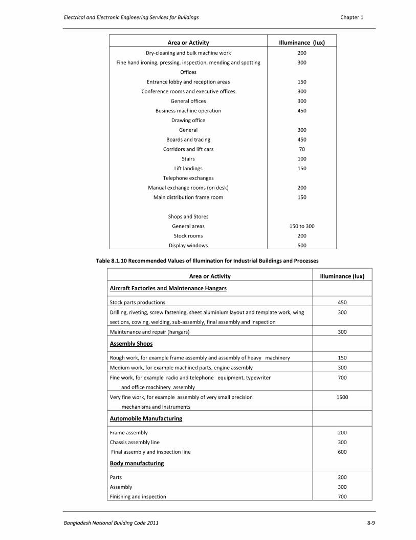
Electrical and Electronic Engineering Services for Buildings Chapter 1
Bangladesh National Building Code 2011 8‐9
Area or Activity Illuminance (lux)
Dry‐cleaning and bulk machine work
Fine hand ironing, pressing, inspection, mending and spotting
Offices
Entrance lobby and reception areas
Conference rooms and executive offices
General offices
Business machine operation
Drawing office
General
Boards and tracing
Corridors and lift cars
Stairs
Lift landings
Telephone exchanges
Manual exchange rooms (on desk)
Main distribution frame room
Shops and Stores
General areas
Stock rooms
Display windows
200
300
150
300
300
450
300
450
70
100
150
200
150
150 to 300
200
500
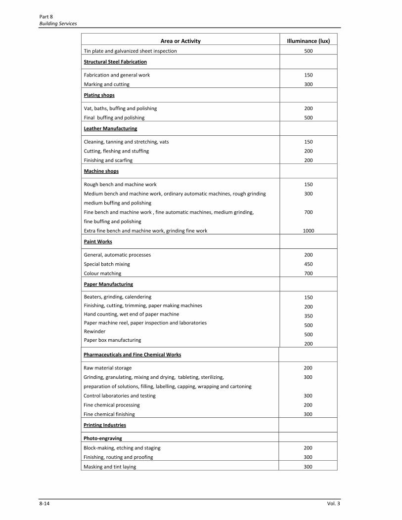
Table 8.1.10 Recommended Values of Illumination for Industrial Buildings and Processes
Area or Activity Illuminance (lux)
Aircraft Factories and Maintenance Hangars
Stock parts productions 450
Drilling, riveting, screw fastening, sheet aluminium layout and template work, wing
sections, cowing, welding, sub‐assembly, final assembly and inspection
300
Maintenance and repair (hangars) 300
Assembly Shops
Rough work, for example frame assembly and assembly of heavy machinery 150
Medium work, for example machined parts, engine assembly 300
Fine work, for example radio and telephone equipment, typewriter
and office machinery assembly
700
Very fine work, for example assembly of very small precision
mechanisms and instruments
1500
Automobile Manufacturing
Frame assembly
Chassis assembly line
Final assembly and inspection line
Body manufacturing
200
300
600
Parts
Assembly
Finishing and inspection
200
300
700
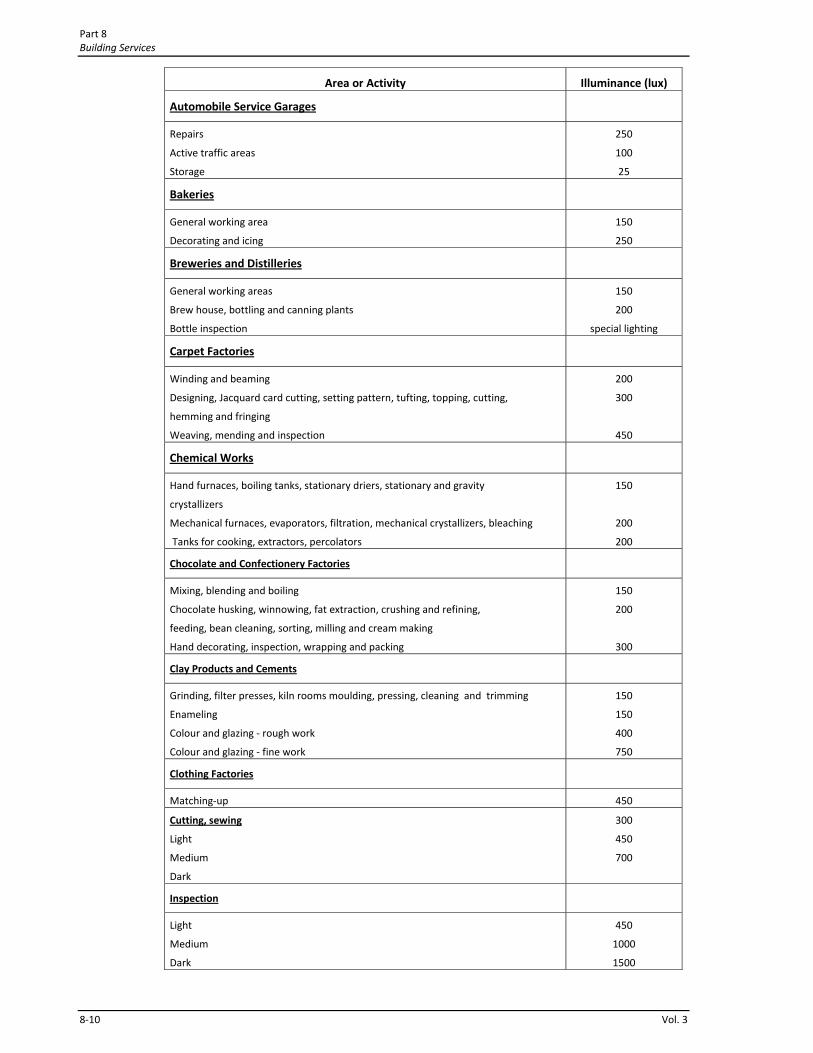
Part 8 Building Services
8‐10 Vol. 3
Area or Activity Illuminance (lux)
Automobile Service Garages
Repairs
Active traffic areas
Storage
250
100
25
Bakeries
General working area
Decorating and icing
150
250
Breweries and Distilleries
General working areas
Brew house, bottling and canning plants
Bottle inspection
150
200
special lighting
Carpet Factories
Winding and beaming
Designing, Jacquard card cutting, setting pattern, tufting, topping, cutting,
hemming and fringing
Weaving, mending and inspection
200
300
450
Chemical Works
Hand furnaces, boiling tanks, stationary driers, stationary and gravity
crystallizers
Mechanical furnaces, evaporators, filtration, mechanical crystallizers, bleaching
Tanks for cooking, extractors, percolators
150
200
200
Chocolate and Confectionery Factories
Mixing, blending and boiling
Chocolate husking, winnowing, fat extraction, crushing and refining,
feeding, bean cleaning, sorting, milling and cream making
Hand decorating, inspection, wrapping and packing
150
200
300
Clay Products and Cements
Grinding, filter presses, kiln rooms moulding, pressing, cleaning and trimming
Enameling
Colour and glazing ‐ rough work
Colour and glazing ‐ fine work
150
150
400
750
Clothing Factories
Matching‐up 450
Cutting, sewing
Light
Medium
Dark
300
450
700
Inspection
Light
Medium
Dark
450
1000
1500
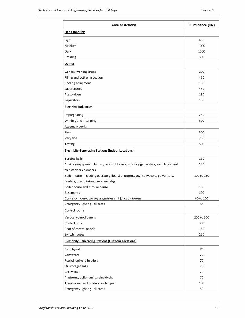
Electrical and Electronic Engineering Services for Buildings Chapter 1
Bangladesh National Building Code 2011 8‐11
Area or Activity Illuminance (lux)
Hand tailoring
Light
Medium
Dark
Pressing
450
1000
1500
300
Dairies
General working areas
Filling and bottle inspection
Cooling equipment
Laboratories
Pasteurizers
Separators
200
450
150
450
150
150
Electrical Industries
Impregnating 250
Winding and insulating 500
Assembly works
Fine
Very fine
500
750
Testing 500
Electricity Generating Stations (Indoor Locations)
Turbine halls
Auxiliary equipment, battery rooms, blowers, auxiliary generators, switchgear and
transformer chambers
Boiler house (including operating floors) platforms, coal conveyors, pulverizers,
feeders, precipitators, soot and slag
Boiler house and turbine house
Basements
Conveyor house, conveyor gantries and junction towers
150
150
100 to 150
150
100
80 to 100
Emergency lighting ‐ all areas 30
Control rooms
Vertical control panels
Control desks
Rear of control panels
Switch houses
200 to 300
300
150
150
Electricity Generating Stations (Outdoor Locations)
Switchyard
Conveyors
Fuel oil delivery headers
Oil storage tanks
Cat‐walks
Platforms, boiler and turbine decks
Transformer and outdoor switchgear
Emergency lighting ‐ all areas
70
70
70
70
70
70
100
50
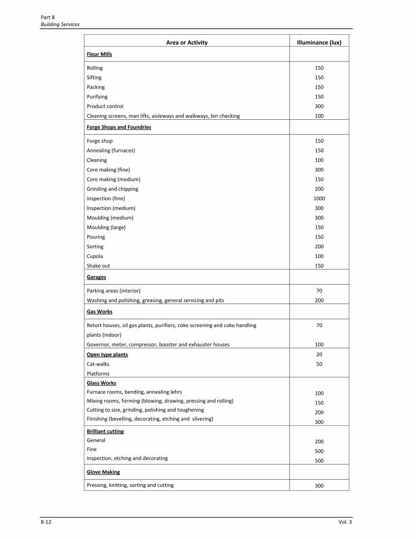
Part 8 Building Services
8‐12 Vol. 3
Area or Activity Illuminance (lux)
Flour Mills
Rolling
Sifting
Packing
Purifying
Product control
Cleaning screens, man lifts, aisleways and walkways, bin checking
150
150
150
150
300
100
Forge Shops and Foundries
Forge shop
Annealing (furnaces)
Cleaning
Core making (fine)
Core making (medium)
Grinding and chipping
Inspection (fine)
Inspection (medium)
Moulding (medium)
Moulding (large)
Pouring
Sorting
Cupola
Shake out
150
150
100
300
150
200
1000
300
300
150
150
200
100
150
Garages
Parking areas (interior)
Washing and polishing, greasing, general servicing and pits
70
200
Gas Works
Retort houses, oil gas plants, purifiers, coke screening and coke handling
plants (indoor)
Governor, meter, compressor, booster and exhauster houses
70
100
Open type plants
Cat‐walks
Platforms
20
50
Glass Works
Furnace rooms, bending, annealing lehrs
Mixing rooms, forming (blowing, drawing, pressing and rolling)
Cutting to size, grinding, polishing and toughening
Finishing (bevelling, decorating, etching and silvering)
100
150
200
300
Brilliant cutting
General
Fine
Inspection, etching and decorating
200
500
500
Glove Making
Pressing, knitting, sorting and cutting 300

Electrical and Electronic Engineering Services for Buildings Chapter 1
Bangladesh National Building Code 2011 8‐13
Area or Activity Illuminance (lux)
Sewing
Light
Medium
Dark
300
450
700
Inspection
Light
Medium
Dark
450
1000
1500
Hosiery and Knitwear
Circular and flat knitting machines, universal winders, cutting out, folding
and pressing
300
Lock‐stitch and overlocking machines
Light
Medium
Dark
Mending
Examining and hand finishing, light, medium and dark
Linking or running on
300
450
700
1500
700
450
Iron and Steel Works
Manufacturing by open hearth
Stock yard
Charging floor
Slag pits
Control platforms
Mould yard
Hot top
Hot top storage
Stripping yard
Scrap stockyard
Mixer building
Calcining building
20
100
100
100
25
100
100
100
20
100
50
Rolling mills
Blooming, slabbing, hot strip, hot sheet
Cold strip, plate
Pipe, rod, tube, wire drawing
Merchant and sheared plate
100
150
200
100
Tin plate mills
Tinning and galvanizing
Cold strip rolling
Motor room, machine room
200
200
150
Sheet metal works
Miscellaneous machines, ordinary bench work
Pressing, folding, stamping, shearing, punching and medium bench work
200
200
Part 8 Building Services
8‐14 Vol. 3
Area or Activity Illuminance (lux)
Tin plate and galvanized sheet inspection 500
Structural Steel Fabrication
Fabrication and general work
Marking and cutting
150
300
Plating shops
Vat, baths, buffing and polishing
Final buffing and polishing
200
500
Leather Manufacturing
Cleaning, tanning and stretching, vats
Cutting, fleshing and stuffing
Finishing and scarfing
150
200
200
Machine shops
Rough bench and machine work
Medium bench and machine work, ordinary automatic machines, rough grinding
medium buffing and polishing
Fine bench and machine work , fine automatic machines, medium grinding,
fine buffing and polishing
Extra fine bench and machine work, grinding fine work
150
300
700
1000
Paint Works
General, automatic processes
Special batch mixing
Colour matching
200
450
700
Paper Manufacturing
Beaters, grinding, calendering
Finishing, cutting, trimming, paper making machines
Hand counting, wet end of paper machine
Paper machine reel, paper inspection and laboratories
Rewinder
Paper box manufacturing
150
200
350
500
500
200
Pharmaceuticals and Fine Chemical Works
Raw material storage
Grinding, granulating, mixing and drying, tableting, sterilizing,
preparation of solutions, filling, labelling, capping, wrapping and cartoning
Control laboratories and testing
Fine chemical processing
Fine chemical finishing
200
300
300
200
300
Printing Industries
Photo‐engraving
Block‐making, etching and staging
Finishing, routing and proofing
200
300
Masking and tint laying 300

Electrical and Electronic Engineering Services for Buildings Chapter 1
Bangladesh National Building Code 2011 8‐15
Area or Activity Illuminance (lux)
Colour Printing
Inspection area
700
Type foundries
Matrix making, dressing type
Front assembly and sorting
Hand casting
Machine casting
250
200
300
200
Printing plants
Machine composition and imposing stones
Presses
Composition room
Proof reading
Colour inspection and appraisal
200
300
450
300
1000
Electrotyping
Block‐making, electroplating, washing and baking
Moulding, finishing and routing
200
300
Rubber Tyre and Tube Manufacturing
Stock preparation
Plasticating, milling
Calendering
100
150
Fabric Preparation
Stock cutting, bead building
Tube tubing machines
Tread tubing machines
250
250
250
Tyre building
Solid tyre
Pneumatic tyre
150
250
Curing department
Tubing curing, casing curing 350
Final Inspection
Tube, casing
Wrapping
1000
200
Shoe Manufacturing (Leather)
Cutting and stitching
Cutting tables
Marking, buttonholing skiving, sorting and counting
450
450
Stitching
Light materials 300
Dark materials 1000
Making and finishing
Nailers, sole layers, welt beaters and scarfers, trimmers, welters,
lasters, edge setters, sluggers, randers, wheelers, treers, cleaning,
spraying, buffing, polishing, embossing
600
Part 8 Building Services
8‐16 Vol. 3
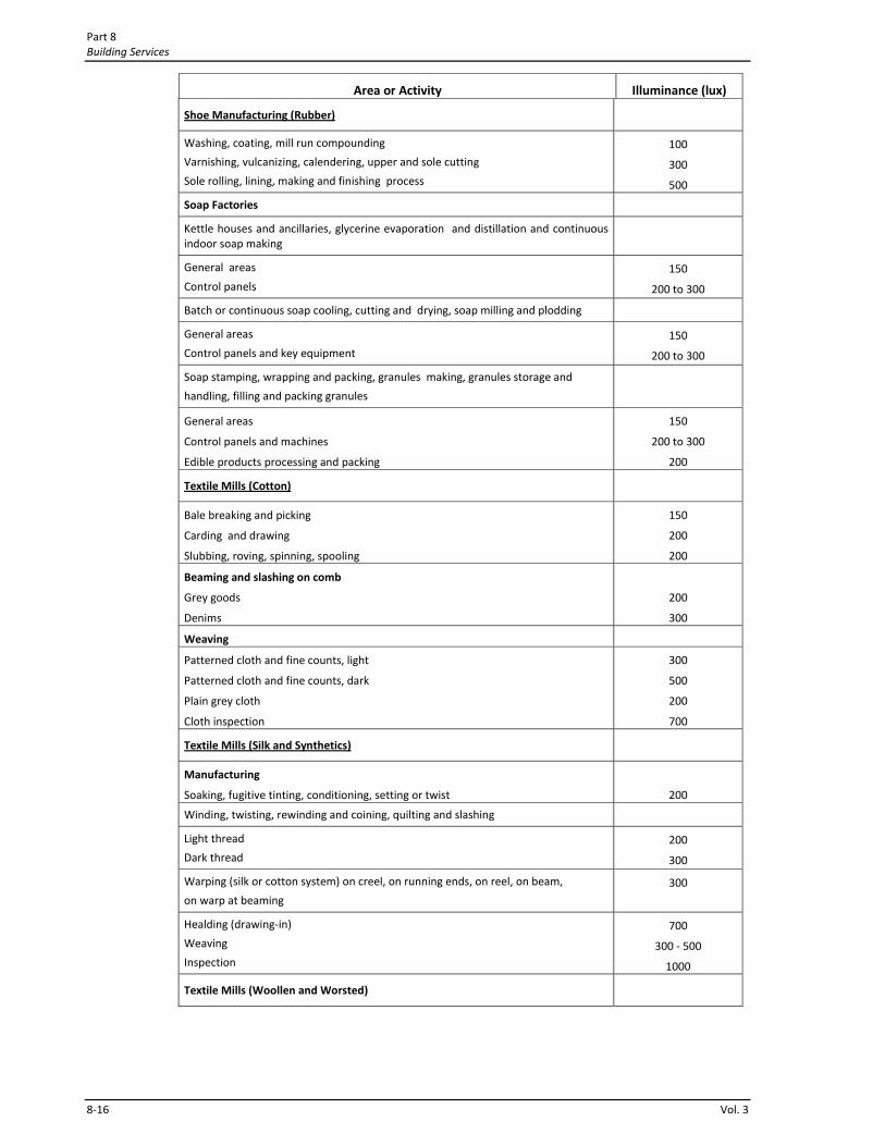
Area or Activity Illuminance (lux)
Shoe Manufacturing (Rubber)
Washing, coating, mill run compounding
Varnishing, vulcanizing, calendering, upper and sole cutting
Sole rolling, lining, making and finishing process
100
300
500
Soap Factories
Kettle houses and ancillaries, glycerine evaporation and distillation and continuous indoor soap making
General areas
Control panels
150
200 to 300
Batch or continuous soap cooling, cutting and drying, soap milling and plodding
General areas
Control panels and key equipment
150
200 to 300
Soap stamping, wrapping and packing, granules making, granules storage and
handling, filling and packing granules
General areas
Control panels and machines
Edible products processing and packing
150
200 to 300
200
Textile Mills (Cotton)
Bale breaking and picking
Carding and drawing
Slubbing, roving, spinning, spooling
150
200
200
Beaming and slashing on comb
Grey goods
Denims
200
300
Weaving
Patterned cloth and fine counts, light
Patterned cloth and fine counts, dark
Plain grey cloth
Cloth inspection
300
500
200
700
Textile Mills (Silk and Synthetics)
Manufacturing
Soaking, fugitive tinting, conditioning, setting or twist
200
Winding, twisting, rewinding and coining, quilting and slashing
Light thread
Dark thread
200
300
Warping (silk or cotton system) on creel, on running ends, on reel, on beam,
on warp at beaming
300
Healding (drawing‐in)
Weaving
Inspection
700
300 ‐ 500
1000
Textile Mills (Woollen and Worsted)
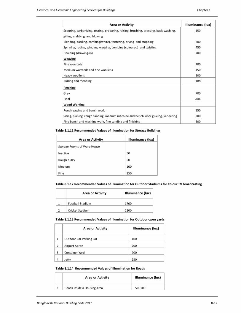
Electrical and Electronic Engineering Services for Buildings Chapter 1
Bangladesh National Building Code 2011 8‐17
Area or Activity Illuminance (lux)
Scouring, carbonizing, testing, preparing, raising, brushing, pressing, back‐washing,
gilling, crabbing and blowing
Blending, carding, combing(white), tentering, drying and cropping
Spinning, roving, winding, warping, combing (coloured) and twisting
Healding (drawing‐in)
150
200
450
700
Weaving
Fine worsteds
Medium worsteds and fine woollens
Heavy woollens
700
450
300
Burling and mending 700
Perching
Grey
Final
700
2000
Wood Working
Rough sawing and bench work
Sizing, planing, rough sanding, medium machine and bench work glueing, veneering
Fine bench and machine work, fine sanding and finishing
150
200
300
Table 8.1.11 Recommended Values of Illumination for Storage Buildings
Area or Activity Illuminance (lux)
Storage Rooms of Ware House
Inactive
Rough bulky
Medium
Fine
50
50
100
250
Table 8.1.12 Recommended Values of Illumination for Outdoor Stadiums for Colour TV broadcasting
Area or Activity Illuminance (lux)
1 Football Stadium 1700
2 Cricket Stadium 2200
Table 8.1.13 Recommended Values of Illumination for Outdoor open yards
Area or Activity Illuminance (lux)
1 Outdoor Car Parking Lot 100
2 Airport Apron 200
3 Container Yard 200
4 Jetty 250
Table 8.1.14 Recommended Values of Illumination for Roads
Area or Activity Illuminance (lux)
1 Roads inside a Housing Area 50‐ 100

Part 8 Building Services
8‐18 Vol. 3
2 Roads in a Congested Town / City Area 50‐ 100
3 Wide Roads with dividers 100 ‐ 120
4 Avenues 100 ‐ 120
1.2.7 Illumination of Exit Signs and Means of Escape
1.2.7.1 Exit Signs
1.2.7.1.1 All required exit signs shall be illuminated at night, or during dark periods within the area served.
1.2.7.1.2 Exit signs may be illuminated either by lamps external to the sign or by lamps contained within the sign. The source of illumination shall provide not less than 50 lux at the illuminated surface with a contrast of not less than 0.5. Approved self‐luminous signs which provide evenly illuminated letters having a minimum luminance of 0.2 cd/m2 may also be used.
1.2.7.1.3 Exit signs within an area where the normal lighting may be deliberately dimmed or extinguished, such as places of entertainment, shall be illuminated either by lamps contained within the sign or by approved self‐luminous signs.
1.2.7.2 Means of Escape Lighting
1.2.7.2.1 The means of escape and exit access in buildings requiring more than one exit shall be equipped with artificial lighting. The lighting facilities so installed shall provide the required level of illumination continuously during the period when the use of the building requires the exits to be available.
1.2.7.2.2 The intensity of illumination at floor level by means of escape lighting shall not be less than 10 lux, except that the minimum required floor level illumination of aisles in assembly halls, theatres and cinema during projection of motion or still pictures by directed light shall not be less than 2 lux.
1.2.7.2.3 The illumination of exit signs and the lighting of the means of escape and exit access shall be powered by an alternate or emergency electrical system to ensure continued illumination for a duration of not less than 30 minutes after the failure of primary power supply.
1.2.8 Selection of Appropriate Type of Lamp
It is important to select appropriate types of lamps for each purpose. The lamps which are used for various purposes are:
(i) General Service Lamps (GLS) / Incandescent Lamps
General Service Lamps (GLS) are well known Incandescent Lamps. These are available in a number of watt ratings. However, most commonly used ratings are 40W, 60W, 100W. 150W & 200W rated lamps are also used for special applications. These types of lamps are inefficient and should be avoided in design consideration. For Kitchen, Cooking Areas of a Hotel, Serving Counters of a Food Shop or Hotel, Porche, Living Room, Toilet, Corridor, Veranda, Bed Room the following lamps perform better in terms of light output to watts ratio. This type of lamp may be used for almost all interior and exterior applications but from energy saving point of view other lamps perform better in terms of light output to watts ratio.
(ii) Fluorescent Lamps (FL):
These are available in 20W and 40W ratings. These lamps are strongly recommended for Reading Room, Educational buildings, Laboratories, Office Room, Commercial Space applications, Factory illumination, Illumination of areas around Industrial Plant and Machineries, Exterior Lighting applications.
40W FL should be used wherever possible because a 40W FL is more energy efficient compared to a 20W FL. These are long life lamps, have wide applications and are advantageous in many respects.
(iii) Compact Fluorescent Lamp( CFL) Energy Saving Lamps:

Electrical and Electronic Engineering Services for Buildings Chapter 1
Bangladesh National Building Code 2011 8‐19
CFL Lamps are available in a number of watts ratings e.g., 4W, 7W, 11W, 14W & 24W. CFLs have been finding wide application for almost all applications because of their high Light output to watts ratio and also because of the attractive light colour. CFL lamps, therefore, should be widely used for energy saving purpose.
However, for Reading areas, Library areas, Educational buildings, Laboratories Fluorescent Lights give better service and thus should be selected for these purposes. It is worthwhile mentioning that Fluorescent lamps with high quality ballasts meet the energy saving purpose.
(iv) LED Lights: Compact light fitting formed using a cluster of white LED is currently used to replace a conventional lamp. An
LED operates at very small amount of voltage. These are good for lighting, Energy Efficient, have almost negligible heat dissipation. These are good for relaxed environment interior lighting. LED lights are becoming more and more popular because of much lower power consumption compared to other lamps.
(v) Halogen lamp:
Halogen Lamps are used for Spot Lights, Decorative lights in shops and commercial spaces, Inside Show Cases, Stage Lighting, Projection lights. Due to High temperature rise and UV light output these should be avoided for interior lighting unless needed.
(vi) Mercury Vapour Lamp
These have been widely used for Shops, Streets, For High Bay Lighting, Warehouse Lighting and similar special lighting. Most likely, this type of lamp will be discontinued within next five to six years due some of it’s ill effects. Metal Halide Lamp is coming up as a better alternative to Mercury Vapour Lamp.
(vii) Metal Halide Lamp:
These are available in a number of watts ratings e.g., 150W, 200W, 250W, 500W, 1000W, 2000W. Good for exterior lighting, indoor and out door athletic facilities, for High Bay Lighting, Warehouse Lighting. These are required where massive Flood Lighting is required from high altitudes for coverage of large areas.
(viii) HP Sodium Lamp:
These are available in a number of watts ratings e.g., 40W, 50W, 70W, 100W, 150W, 250W, 400W, 1000W. Good for exterior lighting, Lighting for areas where higher concentration of vehicles and people exist eg. Street Lighting, Building Exterior Lighting, Security Lighting.
(ix) Low Pressure Sodium Lamp:
For outdoor lighting such as street lights and security lighting where faithful color rendition is considered unimportant. May be used for street lights, observatory, parking lot and similar types of areas.
(x) Solar Power LED Street/Security Light: For outdoor lighting such as street lights, security lighting, Parking area etc this types of lamps may be used. These lights are energy efficient and environment friendly.
1.3 Electrical and Electronic Installations in Buildings
1.3.1 Aim of the Codes of this Section
The aim of the codes and guidelines presented in this section is to make sure that the Electrical and Electronic installations in buildings are safe (i) for persons, (ii) for the buildings and (iii) for the contents of the buildings, from electrical hazards arising from the use of electricity for light, heat, power, automation, control, communications and similar other purposes.
The codes and guidelines presented in this section are set for ensuring minimum standards for electric and electronic wiring and for the installation of equipment within / in public and private buildings, industries and other similar premises.
1.3.2 Scope
This section covers:
a) installation of electrical cables / conductors and equipment in public and private buildings, industries and other similar premises,
Part 8 Building Services
8‐20 Vol. 3
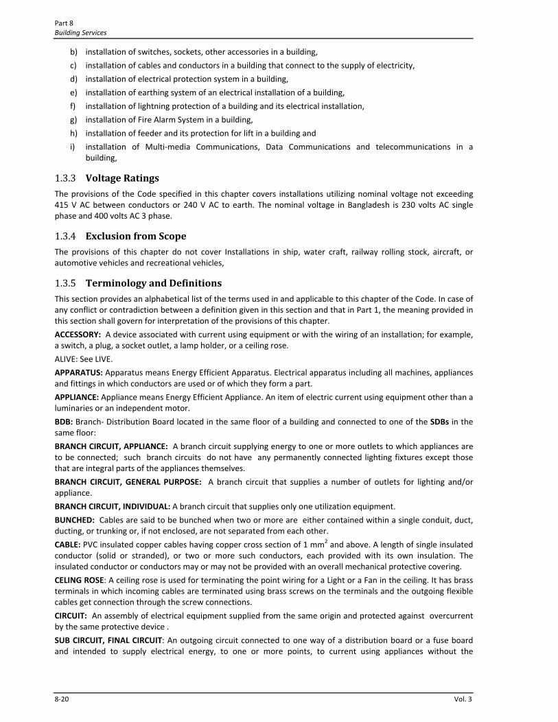
b) installation of switches, sockets, other accessories in a building,
c) installation of cables and conductors in a building that connect to the supply of electricity,
d) installation of electrical protection system in a building,
e) installation of earthing system of an electrical installation of a building,
f) installation of lightning protection of a building and its electrical installation,
g) installation of Fire Alarm System in a building,
h) installation of feeder and its protection for lift in a building and
i) installation of Multi‐media Communications, Data Communications and telecommunications in a building,
1.3.3 Voltage Ratings
The provisions of the Code specified in this chapter covers installations utilizing nominal voltage not exceeding 415 V AC between conductors or 240 V AC to earth. The nominal voltage in Bangladesh is 230 volts AC single phase and 400 volts AC 3 phase.
1.3.4 Exclusion from Scope
The provisions of this chapter do not cover Installations in ship, water craft, railway rolling stock, aircraft, or automotive vehicles and recreational vehicles,
1.3.5 Terminology and Definitions
This section provides an alphabetical list of the terms used in and applicable to this chapter of the Code. In case of any conflict or contradiction between a definition given in this section and that in Part 1, the meaning provided in this section shall govern for interpretation of the provisions of this chapter.
ACCESSORY: A device associated with current using equipment or with the wiring of an installation; for example, a switch, a plug, a socket outlet, a lamp holder, or a ceiling rose.
ALIVE: See LIVE.
APPARATUS: Apparatus means Energy Efficient Apparatus. Electrical apparatus including all machines, appliances and fittings in which conductors are used or of which they form a part.
APPLIANCE: Appliance means Energy Efficient Appliance. An item of electric current using equipment other than a luminaries or an independent motor.
BDB: Branch‐ Distribution Board located in the same floor of a building and connected to one of the SDBs in the same floor:
BRANCH CIRCUIT, APPLIANCE: A branch circuit supplying energy to one or more outlets to which appliances are to be connected; such branch circuits do not have any permanently connected lighting fixtures except those that are integral parts of the appliances themselves.
BRANCH CIRCUIT, GENERAL PURPOSE: A branch circuit that supplies a number of outlets for lighting and/or appliance.
BRANCH CIRCUIT, INDIVIDUAL: A branch circuit that supplies only one utilization equipment.
BUNCHED: Cables are said to be bunched when two or more are either contained within a single conduit, duct, ducting, or trunking or, if not enclosed, are not separated from each other.
CABLE: PVC insulated copper cables having copper cross section of 1 mm2 and above. A length of single insulated conductor (solid or stranded), or two or more such conductors, each provided with its own insulation. The insulated conductor or conductors may or may not be provided with an overall mechanical protective covering.
CELING ROSE: A ceiling rose is used for terminating the point wiring for a Light or a Fan in the ceiling. It has brass terminals in which incoming cables are terminated using brass screws on the terminals and the outgoing flexible cables get connection through the screw connections.
CIRCUIT: An assembly of electrical equipment supplied from the same origin and protected against overcurrent by the same protective device .
SUB CIRCUIT, FINAL CIRCUIT: An outgoing circuit connected to one way of a distribution board or a fuse board and intended to supply electrical energy, to one or more points, to current using appliances without the
Electrical and Electronic Engineering Services for Buildings Chapter 1
Bangladesh National Building Code 2011 8‐21
intervention of a further distribution fuse board other than a one‐way board. It includes all branches and extensions derived from that particular way in the distribution board or fuse board.
CIRCUIT BREAKER: A device designed to open and close a circuit by nonautomatic means and to open the circuit automatically on a predetermined overcurrent, without injury to itself when properly applied within its rating.
CIRCUIT BREAKER: A device used to break a circuit during over current or short circuit condition. An LV Circuit Breaker is used in a low voltage distribution system and an HV Circuit Breaker is used in a high voltage distribution system.
CORD, FLEXIBLE CABLE: A flexible cable having large number of strands of conductors of small cross‐sectional area with a soft PVC insulation. Two flexible cords twisted together may be termed as twin flexible cord. However, some flexible cords are made following thestyle of a twin core PVC insulated copper cables but much soft and flexible.
CUTOUT: Any appliance for automatically interrupting the transmission of energy through a conductor when the current rises above some predetermined value. A cutout contains a part for holding either fuse wire (rectangular cross section type) or a part for holding tubular fuse (cylindrical body rectangular cross section type). (see Fuse)
DB: Distribution Board. This may be the box where the main incoming cable enters and terminates from the main service feed connection. The SDBs get feed from a DB.
DEMAND FACTOR : The ratio of the maximum demand of a system, or part of a system, to the total connected load of the system or the part of the system under consideration.
DUCT : A closed passageway formed underground or in a structure and intended to receive one or more cables which may be drawn in.
EARTH : The conductive mass of the earth, whose electric potential at any point is conventionally taken as zero.
EARTH ELECTRODE: A metal plate, pipe or other conductor electrically connected to the general mass of the earth.
EARTH LEAD WIRE: The final conductor by which the connection to the earth electrode is made.
EARTH CONTINUITY CONDUCTOR (ECC): The conductor, including any clamp, connecting to the earthing lead or to each other, those parts of an installation which are required to be earthed. It may be in whole or in part the metal conduit or the metal sheath or armour of the cables, or the special continuity conductor of a cable or flexible cord incorporating such a conductor. ECCs of appropriate size must run from an MDB to it’s DBs, from a DB to its corresponding SDBs, from an SDB to the Switch Boards under this SDB, from an SDB to the BDBs if there are any, from a BDB to the Switch Boards under this BDB, from an SDB or a BDB to the Sockets under this SDB or BDB.
EDB: Emergency Distribution Board. This may be the box where the main incoming cable from the Emergency or Standby Generator Panel enters and. The ESDBs get feed from a EDB.
EFDB: Emergency Floor Distribution Board located in each of the floors of a multistoried building. The EDBs get feed from EFDB.
ENGINEER‐IN‐CHARGE: An engineer responsible for implementation /execution of the work of a building or a project. Such an engineer is expected to have significant knowledge in Electrical Engineering, Electrical Construction, Measurement, Codes and Practices of such work and availability of different materials needed for the construction.
FDB: Floor Distribution Board located in each of the floors of a multistoried building. The DBs get feed from FDB.
FUSE : A device that, by the fusion of one or more of its specially designed and proportioned components, opens the circuit in which it is inserted when the current through it exceeds a given value for a sufficient time. Fuse is generally made of fusible wires of appropriate ratings which is either mounted inside glass tubes or porcelain tubes or on a two terminal cutout.
FUSE SWITCH: A composite unit, comprising a switch with the fuse contained in, or mounted on, the moving member of the switch.
LIGHTING FITTING: A device for supporting or containing a lamp or lamps (for example, fluorescent or incandescent) together with any holder, shade, or reflector; for example, a bracket, a pendant with ceiling rose, or a portable unit.
INSULATION : Suitable non‐conducting material, enclosing, surrounding or supporting a conductor. Usually PVC, polymer, specially treated rubber.
LIVE : Electrically charged so as to have a potential different from that of earth. Also known as ALIVE.

Part 8 Building Services
8‐22 Vol. 3
LUMINAIRE: A complete light fitting consisting of lamp, holder, starting gears, reflectors, housing and mounting accessories.
LT / LV and HT/ HV: LT or LV in this document indicates 230 Volt single phase and 400 volt 3 phase. HT or HV in this document indicates 11KV Line to line 3 phase system.
MDB: Main Distribution Board. This is the distribution box where the main incoming cable enters and terminates from the main service feed connection of a large building. The FDBs get feed from MDB.
OVER‐CURRENT : A current exceeding the rated current. For conductors, the rated value is the nominal current carrying capacity.
PANEL BOARD : A single panel or a group of panel units designed for assembly in the form of a single panel including buses, automatic overcurrent devices, and with or without switches for the control of light, heat, or power circuits, designed to be placed in a cabinet or cutout box placed in or against a wall or partition and accessible only from the front.
PLUG : A device carrying metallic contacts in the form of pins, intended for engagement with corresponding socket contacts and arranged for attachment to a flexible cord or cable. A plug may contain tubular fuse inside it although some plugs do not contain fuse.
POINT (in wiring) : A termination of the fixed wiring intended for the connection of current using equipment e.g., a Light, a fan, an exhaust fan.
SDB: Sub‐ Distribution Board located in the same floor of a building and connected to the DB. The BDBs get feed from SDB.
SERVICE : The conductors and equipment required for delivering energy from the electric supply system to the wiring system of the premises served.
SWITCH : A manually operated device for closing and opening or for changing the connection of a circuit. A 5A SPST switch is used for the control of a Light or Fan point. A 5A SPDT switch is also used for the control of a Light or Fan point.
SWITCHBOARD : An assemblage of switchgear with or without instruments; the term, however, does not apply to a group of local switches on a final sub‐circuit where each switch has its own insulating base.
SWITCHGEAR : Main switches, cutouts or fuses, conductors and other apparatus in connection therewith, used for the purpose of controlling or protecting electrical circuits or machines or other current using appliances.
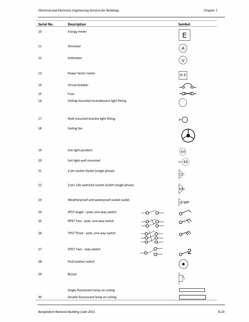
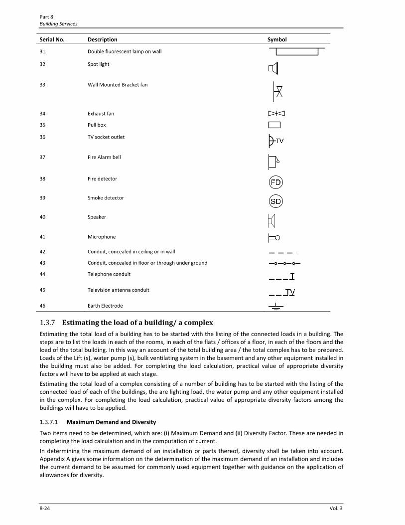
1.3.6 List of Symbols used for Electrical Drawings
A list of general graphical symbols used for electrical drawings is given in Table 2.13. These are given as guideline. In case of justified reasons a designer may modify certain symbol.
Table 8.1.15 Symbols used for Electrical Drawings
Serial No. Description Symbol
1 Main Distribution Board (MDB)
2 Floor Distribution Board (FDB)
3 Distribution Board (DB)
4 Sub‐distribution Board (SDB)
5 Branch Distribution Board (BDB)
6 Switch Board (SB)
7 Telephone Outlet (PSTN)
8 Telephone Outlet (PABX)
9 Change over switch
Electrical and Electronic Engineering Services for Buildings Chapter 1
Bangladesh National Building Code 2011 8‐23
Serial No. Description Symbol
10 Energy meter
11 Ammeter A
12 Voltmeter V
13 Power factor meter P.F
14 Circuit breaker
15 Fuse
16 Ceiling mounted Incandescent light fitting
17 Wall mounted bracket light fitting
18 Ceiling fan
19 Exit light pendant
20 Exit light‐wall mounted
21 2 pin socket Outlet (single phase)
22 3 pin 13A switched socket Outlet (single phase)
23 Weatherproof and waterproof socket outlet
24 SPST Single – pole, one‐way switch
25 DPST Two ‐ pole, one‐way switch
26 TPST Three ‐ pole, one‐way switch
27 SPDT Two – way switch
28 Push button switch
29 Buzzer
Single fluorescent lamp on ceiling
30 Double fluorescent lamp on ceiling
Part 8 Building Services
8‐24 Vol. 3
Serial No. Description Symbol
31 Double fluorescent lamp on wall
32 Spot light
33 Wall Mounted Bracket fan
34 Exhaust fan
35 Pull box
36 TV socket outlet
37 Fire Alarm bell
38 Fire detector
39 Smoke detector
40 Speaker
41 Microphone
42 Conduit, concealed in ceiling or in wall
43 Conduit, concealed in floor or through under ground
44 Telephone conduit
45 Television antenna conduit
46 Earth Electrode
1.3.7 Estimating the load of a building/ a complex
Estimating the total load of a building has to be started with the listing of the connected loads in a building. The steps are to list the loads in each of the rooms, in each of the flats / offices of a floor, in each of the floors and the load of the total building. In this way an account of the total building area / the total complex has to be prepared. Loads of the Lift (s), water pump (s), bulk ventilating system in the basement and any other equipment installed in the building must also be added. For completing the load calculation, practical value of appropriate diversity factors will have to be applied at each stage.
Estimating the total load of a complex consisting of a number of building has to be started with the listing of the connected load of each of the buildings, the are lighting load, the water pump and any other equipment installed in the complex. For completing the load calculation, practical value of appropriate diversity factors among the buildings will have to be applied.
1.3.7.1 Maximum Demand and Diversity
Two items need to be determined, which are: (i) Maximum Demand and (ii) Diversity Factor. These are needed in completing the load calculation and in the computation of current.
In determining the maximum demand of an installation or parts thereof, diversity shall be taken into account. Appendix A gives some information on the determination of the maximum demand of an installation and includes the current demand to be assumed for commonly used equipment together with guidance on the application of allowances for diversity.
Electrical and Electronic Engineering Services for Buildings Chapter 1
Bangladesh National Building Code 2011 8‐25
1.3.7.2 Estimation of Load in KW, in KVA and in Amperes
An estimation of loads is necessary initially for design purpose and later for keeping a track of the growth of load. Estimation of loads means estimation of watts or kilowatts in small scale. In bigger scale the KVA is assessed together with the power factor. A calculation of current is then to be performed for the selection of breakers / fuses and the current carrying cables.
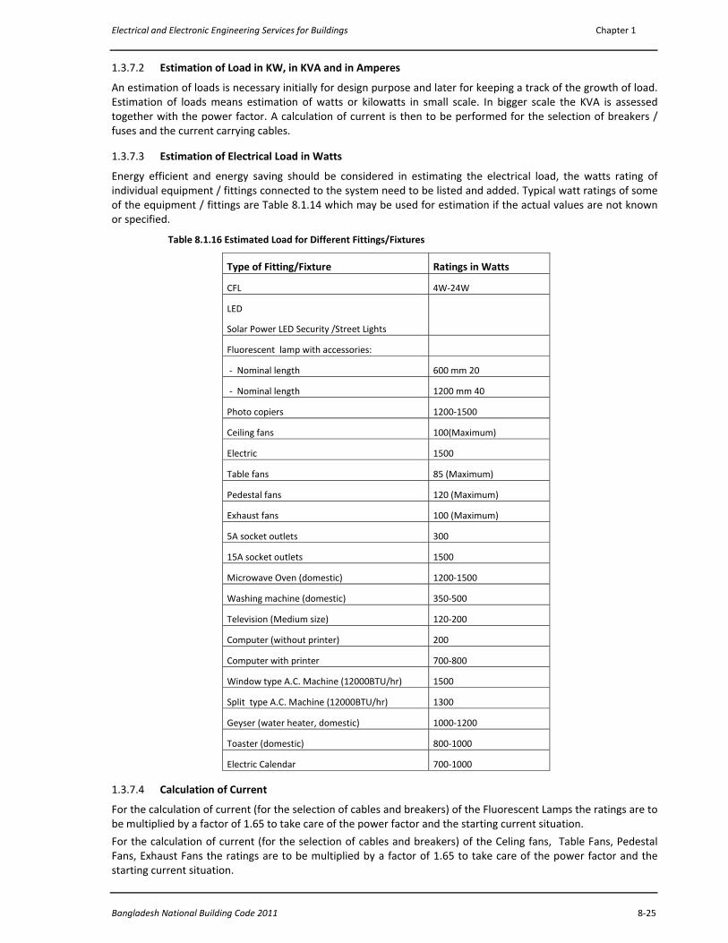
1.3.7.3 Estimation of Electrical Load in Watts
Energy efficient and energy saving should be considered in estimating the electrical load, the watts rating of individual equipment / fittings connected to the system need to be listed and added. Typical watt ratings of some of the equipment / fittings are Table 8.1.14 which may be used for estimation if the actual values are not known or specified.
Table 8.1.16 Estimated Load for Different Fittings/Fixtures
Type of Fitting/Fixture Ratings in Watts
CFL 4W‐24W
LED
Solar Power LED Security /Street Lights
Fluorescent lamp with accessories:
‐ Nominal length 600 mm 20
‐ Nominal length 1200 mm 40
Photo copiers 1200‐1500
Ceiling fans 100(Maximum)
Electric 1500
Table fans 85 (Maximum)
Pedestal fans 120 (Maximum)
Exhaust fans 100 (Maximum)
5A socket outlets 300
15A socket outlets 1500
Microwave Oven (domestic) 1200‐1500
Washing machine (domestic) 350‐500
Television (Medium size) 120‐200
Computer (without printer) 200
Computer with printer 700‐800
Window type A.C. Machine (12000BTU/hr) 1500
Split type A.C. Machine (12000BTU/hr) 1300
Geyser (water heater, domestic) 1000‐1200
Toaster (domestic) 800‐1000
Electric Calendar 700‐1000
1.3.7.4 Calculation of Current
For the calculation of current (for the selection of cables and breakers) of the Fluorescent Lamps the ratings are to be multiplied by a factor of 1.65 to take care of the power factor and the starting current situation.
For the calculation of current (for the selection of cables and breakers) of the Celing fans, Table Fans, Pedestal Fans, Exhaust Fans the ratings are to be multiplied by a factor of 1.65 to take care of the power factor and the starting current situation.

Part 8 Building Services
8‐26 Vol. 3
For the calculation of current (for the selection of cables and breakers) of the small inductive loads (up to 1.0 KW) the ratings are to be multiplied by a factor of 1.65 to take care of the power factor and the starting current situation.
The factor shall be higher for higher rated motors.
1.3.7.5 Minimum Load Densities
While estimating the electrical load, the minimum load densities to be considered are those shown in Table 8.1.17.
Table 8.1.17 Minimum Load Densities
Type of Occupancy Unit Load (Watts/m2)
Non A/C A/C
Residence/ Dwelling : single family 20 75
Residence/ Dwelling : multi‐family (other than hotels) 20 75
Hospitals 32 80
Hotels, including apartment house (excluding any provisions for electric cooking)
24 75
Office and commercial multi‐storeyed buildings 28 75
Industrial building (excluding the loads for machines) 16 ‐
Departmental stores 28 75
Banks 20 75
Restaurants (excluding any provisions for electric cooking) 16 75
Barber shops and beauty parlours 32 75
Schools and Colleges 12 70
Parking area in commercial buildings 4 ‐
Warehouses, large storage areas 2 ‐
1.3.8 Fittings, Fixtures and Accessories
Switch Boards with back boxes and cover plates, Ceiling Roses, Socket Outlets with back boxes, Plugs, Light Fittings, Fans, pull boxes with cover plates have been put in this category, although there may be other items which may be included under Electrical Accessories related to electrical and electronic installations in buildings.
1.3.8.1 Switch Boards
Tumbler Switches have been used for surface wiring and Piano Switches have been used for concealed wiring. Now a day piano switches are also used with surface wiring. Piano Switches are mounted on either a plastic back box or a metal back box. These piano switches are available in gangs. The other alternative is to have piano switches mounted on a Perspex or Ebonite sheet which is then mounted on a metal back box.
The Switches must conform to the relevant BS standard. The minimum ampere rating of switch shall not be below 5A.
Switches may be Single Pole Single Throw (SPST) or Single Pole Double Throw (SPDT) depending on the operation. For some application Double Pole Single Throw (DPST) and Double Pole Double Throw (DPDT) are also available. Usually the DPST switches are made for 10A, 15A and 20A rating.
The phase (Live) wire (Red PVC insulated cable) connection to the point must go through the switch.
The metal / sheet steel back boxes of a switch board must have an earthing terminal to terminate the Earth Continuity Conductor (ECC) coming from a BDB or an SDB.
1.3.8.2 Socket Outlets and Plugs:
In general, all socket outlets must be switched (combined) and shuttered.
Electrical and Electronic Engineering Services for Buildings Chapter 1
Bangladesh National Building Code 2011 8‐27
1.3.8.2.1 General Requirements of Socket Outlets Socket Outlets shall be 13 A switched shuttered 3pin flat pin type.
All socket outlets must be switched (combined) and shuttered and shall be for 3 pin Flat pin type (rectangular cross section) 13A plugs fitted with tubular fuse.
The corresponding plugs must be fitted with fuse. The maximum fuse rating shall be 13A for 13A Sockets. The fuse rating may be smaller depending upon the current rating of the appliances used.
The phase wire (Red cable) shall be connected to the L terminal of the socket outlet through the combined switch and the neutral wire (Black cable) shall be directly connected to the N terminal of the socket. Earth Continuity Conductor (ECC) (Yellow + Green bi‐colour cable) for such a socket outlet shall be connected to the Earth terminal of the socket.
The plug for each 13A socket outlet provided in a building for the use of domestic appliances shall be provided with its own individual fuse. The feed cables for such a circuit must have fuse or miniature circuit breaker (MCB) at the originating point in the Distribution Board or Sub‐Distribution Board or Branch Distribution Board. For some high current applications, additional fuses/ circuit breakers adjacent to the sockets are recommended.
Each socket outlet shall also be controlled by a switch which shall normally be located immediately adjacent thereto or combined therewith.
The phase (Live) wire (Red PVC insulated cable) connection to the socket outlet must be through the switch.
Copper size of the Earth Continuity Conductor (ECC) for such a socket outlet shall not be smaller in size than 1.5 mm2 PVC insulated cable.
1.3.8.2.2 15A /20A rated Round Pin socket outlets may be used for Air Conditioner Outlets and Water Heater Outlets
Under special circumstances, for Air Conditioner Outlets (requiring 15A or 20A), 15A / 20A rated socket outlets for Round Pin Plugs may be used along with a circuit breaker or fuse protection in a box adjacent to the sockets..
Each 15A/ 20A socket outlet provided in a building for the use of domestic appliances such as air‐conditioner, water cooler, etc. shall be provided with its own individual fuse. The feed cables for such a circuit must have fuse or miniature circuit breaker (MCB) at the originating point in the Distribution Board or Sub‐Distribution Board or Branch Distribution Board. For some high current applications, additional fuses/ circuit breakers adjacent to the sockets are recommended.
Each socket outlet shall also be controlled by a switch which shall normally be located immediately adjacent to the Socket or shall be combined with the Socket.
The corresponding plugs for 15A should be fitted with fuse. The maximum fuse rating shall be 15A for 15A Sockets. For a 15A rated socket outlet a 15A rated fuse or a 15A circuit breaker must be placed adjacent to the socket.
For a 20A rated socket outlet a 20A rated fuse or a 20A circuit breaker must be placed adjacent to the socket.
Wiring for sockets shall be radial type of wiring. However, ring type wiring may be used by strictly following the rules given in IEE Wiring regulations BS 7671: 2008, 17th Edition and by using appropriate size of cable.
1.3.8.2.3 Earth Continuity Conductor (ECC) for a Socket The ECC for a socket outlet shall not be smaller in size than 1.5 mm2 PVC insulated annealed copper cable. The colour of the ECC cable insulation shall be Yellow+Green bi‐colour.
1.3.8.2.4 Mounting Height of a Three pin Switched Socket outlet Three pin Switched Shuttered Socket outlets shall be mounted on a wall at a height 254mm above floor level. Switched Shuttered Socket outlets are essential for safety in particular for the safety of infants.
For certain applications like computers, printers, UPS, IPS such sockets may be mounted at a higher level for the ease of operation.
1.3.8.2.5 Restriction on mounting Socket Outlets in wet places No socket outlets shall be provided inside Bath Rooms / Toilets or any other place where the floor may remain wet.
Part 8 Building Services
8‐28 Vol. 3
1.3.8.2.6 5A rated 2 Pin socket outlets 5A rated 2 Pin socket outlets may be used along with the Light and Fan Switch Boards only. Such sockets shall not be used as socket outlets at the skirt level.
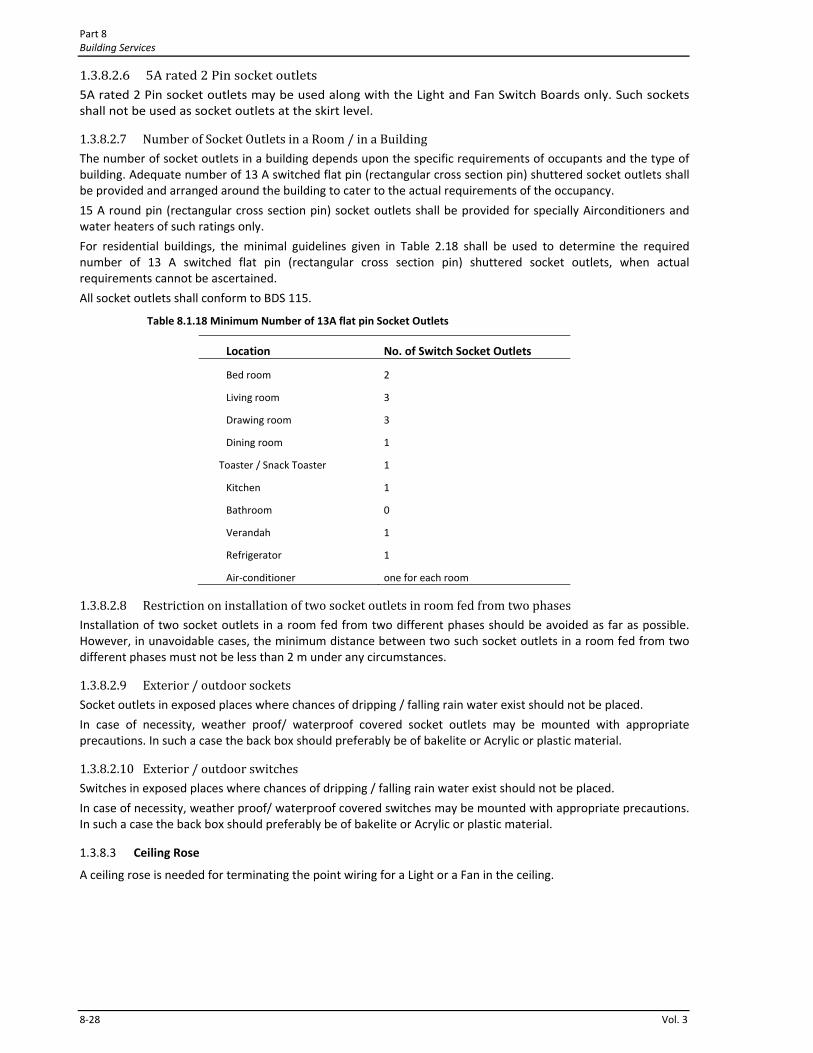
1.3.8.2.7 Number of Socket Outlets in a Room / in a Building The number of socket outlets in a building depends upon the specific requirements of occupants and the type of building. Adequate number of 13 A switched flat pin (rectangular cross section pin) shuttered socket outlets shall be provided and arranged around the building to cater to the actual requirements of the occupancy.
15 A round pin (rectangular cross section pin) socket outlets shall be provided for specially Airconditioners and water heaters of such ratings only.
For residential buildings, the minimal guidelines given in Table 2.18 shall be used to determine the required number of 13 A switched flat pin (rectangular cross section pin) shuttered socket outlets, when actual requirements cannot be ascertained.
All socket outlets shall conform to BDS 115.
Table 8.1.18 Minimum Number of 13A flat pin Socket Outlets
Location No. of Switch Socket Outlets
Bed room 2
Living room 3
Drawing room 3
Dining room 1
Toaster / Snack Toaster 1
Kitchen 1
Bathroom 0
Verandah 1
Refrigerator 1
Air‐conditioner one for each room
1.3.8.2.8 Restriction on installation of two socket outlets in room fed from two phases Installation of two socket outlets in a room fed from two different phases should be avoided as far as possible. However, in unavoidable cases, the minimum distance between two such socket outlets in a room fed from two different phases must not be less than 2 m under any circumstances.
1.3.8.2.9 Exterior / outdoor sockets Socket outlets in exposed places where chances of dripping / falling rain water exist should not be placed.
In case of necessity, weather proof/ waterproof covered socket outlets may be mounted with appropriate precautions. In such a case the back box should preferably be of bakelite or Acrylic or plastic material.
1.3.8.2.10 Exterior / outdoor switches Switches in exposed places where chances of dripping / falling rain water exist should not be placed.
In case of necessity, weather proof/ waterproof covered switches may be mounted with appropriate precautions. In such a case the back box should preferably be of bakelite or Acrylic or plastic material.
1.3.8.3 Ceiling Rose
A ceiling rose is needed for terminating the point wiring for a Light or a Fan in the ceiling.
Electrical and Electronic Engineering Services for Buildings Chapter 1
Bangladesh National Building Code 2011 8‐29
1.3.8.3.1 A ceiling rose shall not be installed in any circuit operating at a voltage normally exceeding 250 volts.
1.3.8.3.2 Normally, a single pendant be suspended from only one ceiling rose using a flexible cord. A ceiling rose shall not be used for the attachment of more than one outgoing flexible cord unless it is specially designed for multiple pendants.
1.3.8.3.3 A ceiling rose shall not contain a fuse terminal as an integral part of it.
1.3.8.3.4 The ceiling rose shall conform to BS 67.
1.3.8.3.5 Luminaire supporting couplers are designed specifically for the mechanical support as well as for the electrical connection of luminaires and shall not be used for the connection of any other equipment.
1.3.8.4 Light Fitting
Switches shall be provided for the control of every light fitting. A switch may control an individual light point or a group of light points.
Where control at more than one position is necessary for a lighting fitting or a group of lighting fittings, as many two‐way or intermediate switches may be provided as the required number of control positions.
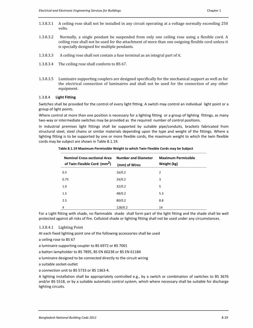
In industrial premises light fittings shall be supported by suitable pipe/conduits, brackets fabricated from structural steel, steel chains or similar materials depending upon the type and weight of the fittings. Where a lighting fitting is to be supported by one or more flexible cords, the maximum weight to which the twin flexible cords may be subject are shown in Table 8.1.19.
Table 8.1.19 Maximum Permissible Weight to which Twin Flexible Cords may be Subject
Nominal Cross‐sectional Area
of Twin Flexible Cord (mm2)
Number and Diameter
(mm) of Wires
Maximum Permissible
Weight (kg)
0.5 16/0.2 2
0.75 24/0.2 3
1.0 32/0.2 5
1.5 48/0.2 5.3
2.5 80/0.2 8.8
4 128/0.2 14
For a Light fitting with shade, no flammable shade shall form part of the light fitting and the shade shall be well protected against all risks of fire. Celluloid shade or lighting fitting shall not be used under any circumstances.
1.3.8.4.1 Lighting Point At each fixed lighting point one of the following accessories shall be used
a ceiling rose to BS 67
a luminaire supporting coupler to BS 6972 or BS 7001
a batten lampholder to BS 7895, BS EN 60238 or BS EN 61184
a luminaire designed to be connected directly to the circuit wiring
a suitable socket‐outlet
a connection unit to BS 5733 or BS 1363‐4.
A lighting installation shall be appropriately controlled e.g., by a switch or combination of switches to BS 3676 and/or BS 5518, or by a suitable automatic control system, which where necessary shall be suitable for discharge lighting circuits.

Part 8 Building Services
8‐30 Vol. 3
1.3.8.4.2 Wires / Cables used inside Light Fittings and any other Fitting Wires / cables used inside a light fitting or any other fittings are mostly flexible types. In some cases single core PVC insulated wiring cables mostly 1mm2 or 1.5 mm2 are used. In such cases the cables must be of high quality in terms of insulation and must have appropriate copper cross section. Such cables are usually terminated in a ceiling rose.
1.3.8.5 Fans
1.3.8.5.1 Ceiling Fan Ceiling fans including their suspension shall conform to BDS 818.
With respect to the position of a lighting fitting, placing a fan in a way that shadows are thrown on the working planes is not acceptable.
Where ceiling fans are provided in large buildings, the chosen unit module are (size) also play an important part. In general, for domestic, office and commercial buildings, for every part of a module to be served by the ceiling fans, it is necessary that the unit module area shall be so chosen that the required number of fans could be suitably located in it, to avoid creation of pockets receiving little or no air circulation.
In general, fans in large halls may be spaced at 3 to 3.5 m in both the directions in the horizontal plane. If building modules do not lend themselves to proper positioning of the required number of ceiling fans, other types of fans, such as air circulators or wall mounted bracket fans shall have to be installed for the areas uncovered by the ceiling fans. In such cases, necessary electrical outlets shall have to be provided for the purpose.
Table 8.1.20 gives the recommended areas to be served by different sizes of ceiling fans where the height of fan blades is at 2.5 m above the finished floor level.
Table 8.1.20 Recommended Fan Sizes in Rooms
Wiring for a ceiling fan outlet from the switch board up to the ceiling fan outlet shall be done through pre‐laid 18 mm dia PVC conduits using 1.5 mm2 PVC insulated 2 cables of Red and Black insulation. A high quality ceiling rose is to be installed at the ceiling fan point for the termination of the wiring and the connection of the two wires of the Fan.
A fan hook is required to be placed during casting of the roof. The fan hook is to be made using a 12.7 mm dia MS rod having at least 600mm on both sides and shall be placed above the MS rod mesh of the roof slab.
1.3.8.5.2 Wall Mounted Bracket Fan For Wall mounted bracket fans shall be mounted on the wall using appropriate rowel bolts. Wiring for a Wall mounted bracket fan outlet from the switch board up to the Wall mounted bracket fan outlet shall be done through pre‐laid 18 mm dia PVC conduits using 1.5 mm2 PVC insulated 2 cables of Red and Black insulation. A high quality ceiling rose is to be installed at the ceiling fan point for the termination of the wiring and the connection of the two wires of the Fan.
1.3.8.5.3 Pedestal Fans and Table Fans: These items are movable. As a result no fixed connections are necessary. Sockets will be used to energize these fans.
1.3.8.5.4 Installation/Mounting of Ventilating Fans or Exhaust Fans Exhaust fans are necessary for spaces, such as toilets, kitchens, canteens and godowns to provide the required air changes. Since the exhaust fans are located generally on the outer walls of a room, appropriate openings in such walls shall be provided right from the planning stage. The sizes and the rpm of the exhaust fans will vary according to the application and the volume for which a fan used. In some applications (such as some industries, big size gas generator room etc.) high rpm fans are essential. In all cases appropriate types of fan need to be chosen and appropriate arrangement need to be made so that rain water cannot get inside the rooms.
Room Area (m2) Fan Sweep
Up to 6 915 mm
Over 6 to 9 1220 mm
Over 9 to 12 1442 mm
Electrical and Electronic Engineering Services for Buildings Chapter 1
Bangladesh National Building Code 2011 8‐31
1.3.8.5.5 Installation/Mounting of Ceiling Fans Ceiling Fans shall be suspended from Fan hooks. Fan hooks are to be placed in position during the casting of the Roof.
1.3.8.5.6 Fan hooks Fan hooks may be concealed (hidden) or may be exposed type. Fan hooks shall be made using MS rods of 12.7 mm diameter. The diameter of this rod shall not be below 9.53 mm under any circumstances.
1.3.8.5.7 Ceiling Roses for Fan Points Appropriate type of ceiling roses must be provided at the Fan points for the termination of the Fan point wiring cables. Connection to the Ceiling Fans will go from the ceiling roses.
1.3.8.5.8 Cutout Box / Circuit Breaker Box If the BDB or the SDB from which a 3‐pin switched shuttered socket receives power is at a significant distance away and the load connected to the socket needs special care an additional cutout box or a circuit breaker box may be placed adjacent to the socket. Such a cutout Box or a Circuit Breaker box shall be placed inside a 18SWG Sheet Steel (coated with two coats of synthetic enamel paint) of appropriate size with appropriate Perspex cover plate. Such a box may be surface fitted or may be concealed fitted. The box shall have a brass terminal for the termination of the ECC.
1.3.9 Distribution Wiring in a Building
1.3.9.1 General
Loads are separated into known and unknown loads.
General illumination is a known load, whether derived from detailed lighting layout, or developed from watts per square meter calculation. Similarly fans are also known loads. Besides these two types, there may be some other known loads.
Number, rating and layout of outlets for general illumination, fans and other known loads should accurately be distributed among a number of branch circuits. These branch circuits should then be carefully loaded with due regard to voltage drop, operating voltage and possible increase in lighting levels in future. On the other hand the sockets are unknown loads. Socket loads will be determined from projections based on the utility of the building and type of applications.
Every installation shall be divided into small circuits (following the rules given in this document) to avoid danger in case of a fault, and to facilitate safe operation, inspection, maintenance and testing. For the establishment of the circuits appropriate type of wiring is needed and appropriate terminations / connections / junctions of these circuits are needed. At the same time appropriate types of protection against faults must be given at different levels. These are to be achieved through installation of appropriate distribution wiring in the building.
1.3.9.2 Distribution Board
A Distribution Board is the junction point of the incoming line and the outgoing lines for the distribution of Electricity throughout the building. The incoming as well as the outgoing lines must have Circuit Breaker protection or Fuse protection. The junctions and terminations of the incoming and outgoing cables are made through copper bars containing bolts and nuts for cable lugs known as bus‐bars. A Distribution board may be named as MDB or FDB or DB or SDB or BDB.
a) MDB stands for Main Distribution Board. This is the distribution box where the main incoming cable enters and terminates from the main service feed connection of a large building. The FDBs get feed from MDB.
b) FDB stands for Floor Distribution Board located in each of the floors of a multistoried building. The DBs get feed from FDB. Usually more than one FDBs are needed.
c) DB is the abbreviation for Distribution Board. This may be the box where the main incoming cable enters and terminates from the main service feed connection. The SDBs get feed from a DB.
d) SDB is used to represent Sub‐ Distribution Board. This board is located in the same floor of a building and connected to the DB. Usually more than one SDBs are needed. The BDBs get feed from SDB.
Part 8 Building Services
8‐32 Vol. 3
e) BDB stands for Branch‐ Distribution Board located in the same floor of a building and connected to the SDB. Usually more than one BDBs are needed.
f) EDB, EFDF, ESDB, EBDB Sections of DB, FDB, SDB, BDB receiving feed from the Emergency Busbar which in turn is getting feed from Standby Generator through changeover switch. These may be separate DBs placed by the corresponding normal supply DBs.
Each of these distribution boards must have bus bars for Line, Neutral and Earthing for a single phase box. A 3‐phase distribution board must have bus bars for Line1, Line2, Line 3, Neutral and Earthing.
These boxes shall be made with sheet steel of not less than 18 SWG thickness and must be appropriately paint finished to match the wall paint.
1.3.9.3 Circuit Wiring
1.3.9.3.1 Separate branch circuits for separate control Separate branch circuits shall be provided for different parts of a building area which need to be separately controlled. A branch circuit should be independently working and should not be affected due to the failure of another branch circuit.
The number of final circuits (also termed as sub‐circuits or circuits) required and the points supplied by any final circuits shall comply with
a) the requirement of over‐current protection,
b) the requirement for isolation and switching, and
c) the selection of cables and conductors.
All final circuits shall be wired using loop wiring system; no joint box shall be used.
Sufficient number of 18 SWG sheet steel made (painted with two coats of grey synthetic enamel paint) pull boxes, with ebonite / perspex sheet cover plate, must be given on the walls near the ceiling. If brick walls are not available, pull boxes must be given in the ceilings.
1.3.9.3.2 For Domestic and Office Buildings 5A Light / Fan Circuits must be used for all Domestic and Residential buildings. 5A Light / Fan Circuits are also to be used for Office and commercial Buildings. The corresponding circuit wire in the BDB/ SDB/ DB then shall be not less than 1.5 mm2.
1.3.9.3.3 For Office and Commercial Buildings having large open floor areas Under unavoidable circumstances, in case of difficulties in forming 5A Light / Fan Circuits for Office and commercial Buildings having large open floor areas, 10A Light / Fan Circuits may be used. The corresponding circuit wire in the BDB/ SDB/ DB then shall be not less than 2.5 mm2.
However use of 5A Light / Fan Circuits is still emphasized.
1.3.9.3.4 For Industrial / Factory Buildings having large open floor areas For Industrial / Factory Buildings having large open floor areas, 10A Light / Fan Circuits may be used.
1.3.9.3.5 For Industrial / Factory Buildings/ Warehouses having too large open floor areas For Industrial / Factory Buildings / Warehouses having large open floor areas, efforts should be given to use circuits not exceeding 10A. The corresponding circuit wire in the BDB/ SDB/ DB then shall be not less than 2.5 mm2.
For Industrial / Factory Buildings having very large open floor areas, 15A Light / Fan Circuits may be used as exceptional cases only. The corresponding circuit breaker in the BDB/ SDB/ DB then shall be not less than 4 mm2.
Increase in the sizes of the above mentioned cables may be required if the distance is too long. Voltage drop calculation will give the guidance in that case.
1.3.9.3.6 Separate branch circuits from miniature circuit breaker (MCB) Separate branch circuits shall be provided from miniature circuit breaker (MCB) of a BDBD/ SDB or fuse of the Fuse distribution boards (FDB) for Light / Fan.
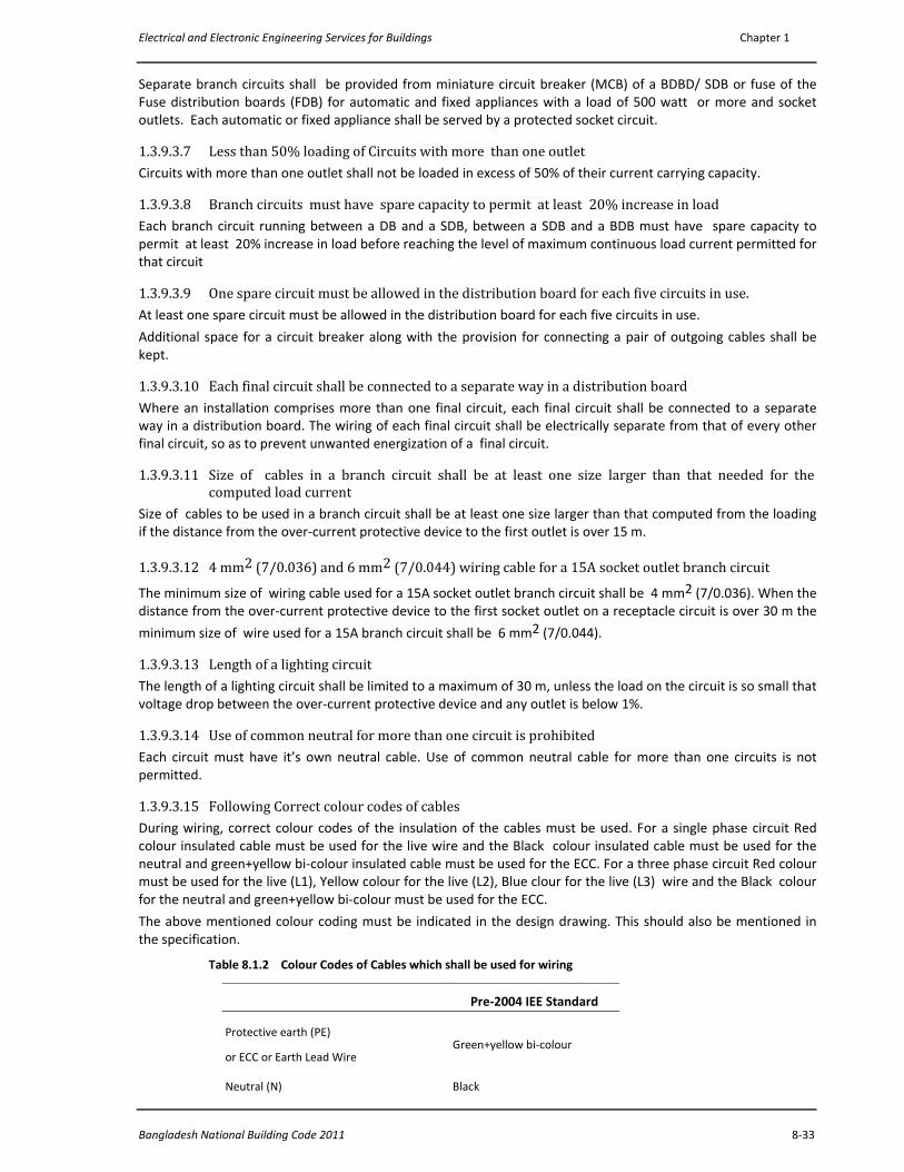
Electrical and Electronic Engineering Services for Buildings Chapter 1
Bangladesh National Building Code 2011 8‐33
Separate branch circuits shall be provided from miniature circuit breaker (MCB) of a BDBD/ SDB or fuse of the Fuse distribution boards (FDB) for automatic and fixed appliances with a load of 500 watt or more and socket outlets. Each automatic or fixed appliance shall be served by a protected socket circuit.
1.3.9.3.7 Less than 50% loading of Circuits with more than one outlet Circuits with more than one outlet shall not be loaded in excess of 50% of their current carrying capacity.
1.3.9.3.8 Branch circuits must have spare capacity to permit at least 20% increase in load Each branch circuit running between a DB and a SDB, between a SDB and a BDB must have spare capacity to permit at least 20% increase in load before reaching the level of maximum continuous load current permitted for that circuit
1.3.9.3.9 One spare circuit must be allowed in the distribution board for each five circuits in use. At least one spare circuit must be allowed in the distribution board for each five circuits in use.
Additional space for a circuit breaker along with the provision for connecting a pair of outgoing cables shall be kept.
1.3.9.3.10 Each final circuit shall be connected to a separate way in a distribution board Where an installation comprises more than one final circuit, each final circuit shall be connected to a separate way in a distribution board. The wiring of each final circuit shall be electrically separate from that of every other final circuit, so as to prevent unwanted energization of a final circuit.
1.3.9.3.11 Size of cables in a branch circuit shall be at least one size larger than that needed for the computed load current
Size of cables to be used in a branch circuit shall be at least one size larger than that computed from the loading if the distance from the over‐current protective device to the first outlet is over 15 m.
1.3.9.3.12 4 mm2 (7/0.036) and 6 mm2 (7/0.044) wiring cable for a 15A socket outlet branch circuit
The minimum size of wiring cable used for a 15A socket outlet branch circuit shall be 4 mm2 (7/0.036). When the distance from the over‐current protective device to the first socket outlet on a receptacle circuit is over 30 m the
minimum size of wire used for a 15A branch circuit shall be 6 mm2 (7/0.044).
1.3.9.3.13 Length of a lighting circuit The length of a lighting circuit shall be limited to a maximum of 30 m, unless the load on the circuit is so small that voltage drop between the over‐current protective device and any outlet is below 1%.
1.3.9.3.14 Use of common neutral for more than one circuit is prohibited Each circuit must have it’s own neutral cable. Use of common neutral cable for more than one circuits is not permitted.
1.3.9.3.15 Following Correct colour codes of cables During wiring, correct colour codes of the insulation of the cables must be used. For a single phase circuit Red colour insulated cable must be used for the live wire and the Black colour insulated cable must be used for the neutral and green+yellow bi‐colour insulated cable must be used for the ECC. For a three phase circuit Red colour must be used for the live (L1), Yellow colour for the live (L2), Blue clour for the live (L3) wire and the Black colour for the neutral and green+yellow bi‐colour must be used for the ECC.
The above mentioned colour coding must be indicated in the design drawing. This should also be mentioned in the specification.
Table 8.1.2 Colour Codes of Cables which shall be used for wiring
Pre‐2004 IEE Standard
Protective earth (PE)
or ECC or Earth Lead Wire Green+yellow bi‐colour
Neutral (N) Black
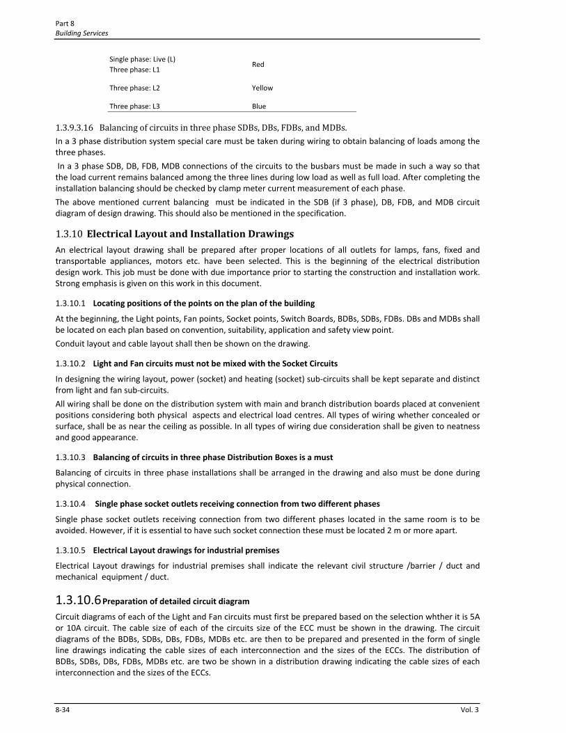
Part 8 Building Services
8‐34 Vol. 3
Single phase: Live (L) Three phase: L1
Red
Three phase: L2 Yellow
Three phase: L3 Blue
1.3.9.3.16 Balancing of circuits in three phase SDBs, DBs, FDBs, and MDBs. In a 3 phase distribution system special care must be taken during wiring to obtain balancing of loads among the three phases.
In a 3 phase SDB, DB, FDB, MDB connections of the circuits to the busbars must be made in such a way so that the load current remains balanced among the three lines during low load as well as full load. After completing the installation balancing should be checked by clamp meter current measurement of each phase.
The above mentioned current balancing must be indicated in the SDB (if 3 phase), DB, FDB, and MDB circuit diagram of design drawing. This should also be mentioned in the specification.
1.3.10 Electrical Layout and Installation Drawings An electrical layout drawing shall be prepared after proper locations of all outlets for lamps, fans, fixed and transportable appliances, motors etc. have been selected. This is the beginning of the electrical distribution design work. This job must be done with due importance prior to starting the construction and installation work. Strong emphasis is given on this work in this document.
1.3.10.1 Locating positions of the points on the plan of the building
At the beginning, the Light points, Fan points, Socket points, Switch Boards, BDBs, SDBs, FDBs. DBs and MDBs shall be located on each plan based on convention, suitability, application and safety view point.
Conduit layout and cable layout shall then be shown on the drawing.
1.3.10.2 Light and Fan circuits must not be mixed with the Socket Circuits
In designing the wiring layout, power (socket) and heating (socket) sub‐circuits shall be kept separate and distinct from light and fan sub‐circuits.
All wiring shall be done on the distribution system with main and branch distribution boards placed at convenient positions considering both physical aspects and electrical load centres. All types of wiring whether concealed or surface, shall be as near the ceiling as possible. In all types of wiring due consideration shall be given to neatness and good appearance.
1.3.10.3 Balancing of circuits in three phase Distribution Boxes is a must
Balancing of circuits in three phase installations shall be arranged in the drawing and also must be done during physical connection.
1.3.10.4 Single phase socket outlets receiving connection from two different phases
Single phase socket outlets receiving connection from two different phases located in the same room is to be avoided. However, if it is essential to have such socket connection these must be located 2 m or more apart.
1.3.10.5 Electrical Layout drawings for industrial premises
Electrical Layout drawings for industrial premises shall indicate the relevant civil structure /barrier / duct and mechanical equipment / duct.
1.3.10.6 Preparation of detailed circuit diagram Circuit diagrams of each of the Light and Fan circuits must first be prepared based on the selection whther it is 5A or 10A circuit. The cable size of each of the circuits size of the ECC must be shown in the drawing. The circuit diagrams of the BDBs, SDBs, DBs, FDBs, MDBs etc. are then to be prepared and presented in the form of single line drawings indicating the cable sizes of each interconnection and the sizes of the ECCs. The distribution of BDBs, SDBs, DBs, FDBs, MDBs etc. are two be shown in a distribution drawing indicating the cable sizes of each interconnection and the sizes of the ECCs.
Electrical and Electronic Engineering Services for Buildings Chapter 1
Bangladesh National Building Code 2011 8‐35
1.3.10.7 Preparation of Electrical Distribution and Wiring Design drawing by an experienced Engineer
Electrical Distribution and Wiring Design drawing of building must be prepared by an Engineer who is knowledgeable and preferably experienced in this subject. For big and multistoried building experience is of utmost importance.
1.3.11 Electrical Wiring in the Interior of Buildings
1.3.11.1 Surface Wiring or Exposed Wiring
Wiring run over the surface of walls and ceilings, whether contained in conduits or not, is termed as surface wiring or exposed wiring.
Single core PVC insulated cupper through PVC Channels or through PVC conduits or through GI pipes of approved quality may be used for surface wiring.
Surface wiring using twin core flat PVC insulated cupper on wooden battens used to be used long back. This is almost discontinued and discouraged now a day.
PVC conduits or GI pipes, when used for surface wiring, shall be clamped with saddles at a spacing not exceeding 600 mm, to the wall or ceiling using plastic rowel plugs with countersunk galvanized screws.
1.3.11.1.1 Surface Wiring using Wood Battens Surface wiring using wood battens is very rare now a day because of evolution of other decent techniques of surface wiring. This method is discouraged. However, in case of extreme necessity this may be used.
The wood battens used in this method shall be made with good quality wood having a minimum thickness of 12 mm. They shall be installed exposed and run straight on the ceiling or wall surfaces. Battens on walls shall be run either horizontally or vertically, and never at an angle. Battens on ceilings shall be run parallel to the edges in either orthogonal direction, and not at an angle, They shall be fixed to the wall or ceiling by rowel plugs and countersunk galvanized screws. The wires shall be fixed to the battens by using galvanized steel clips or brass link clips of required size at a spacing not exceeding 100 mm.
This method is no longer used because of the availability of other surface wiring methods presented below.
1.3.11.1.2 Surface Wiring using PVC Conduits PVC conduits or GI pipes, when used for surface wiring, shall be clamped with saddles at a spacing not exceeding 600 mm, to the wall or ceiling using plastic rowel plugs with countersunk galvanized screws.
The conduits placed concealed inside roof or in wall must have 20 SWG GI pull wires placed during laying of the pipes for pulling the cables later.
1.3.11.1.3 Surface Wiring using PVC Channels Surface wiring may be done using single core PVC insulated cables placed inside surface fixed PVC channels of appropriate size. Fixing of channels must be done using screws in rowel plugs inserted into drilled holes on the walls/ ceilings. The channels must be placed in a straight line with adequate number of screws so that no sag is observed. Cables must not be stressed in the bends. Adequate space must exist inside the channel to put the cables in position without difficulty.
Surface wiring using flexible chords, clips and nails shall not be used in general.
1.3.11.1.4 Surface Wiring using Round core flexible cable with plastic clips and nails
Surface Wiring using exposed Round core flexible cable with plastic clips and long nails have been used for extending a point wiring, for extending a socket wiring due to shift, for add a circuit wiring.
This is not recommended for regular wiring. Instead of using this method, one should go for the recommended surface wiring using single core PVC cables with PVC channels or single core PVC cables with PVC conduits as mentioned above in this document.
For a length of not exceeding 1m this may be used only for shifting an existing Light / Fan point or for shifting an existing socket point only under unavoidable circumstances.
1.3.11.2 Concealed Wiring
Part 8 Building Services
8‐36 Vol. 3
The wires in this type of wiring shall be placed inside GI conduits or PVC conduits that are buried in roofs and in brick/concrete walls. The conduits in the walls shall be run horizontally or vertically, and not at an angle.
Conduits in concrete slabs shall be placed at the centre of thickness and supported during casting by mortar blocks or 'chairs' made of steel bars or any other approved means. All conduits shall be continuous throughout their lengths.
Appropriate planning should be made in which there shall be adequate spare capacity in the conduits placed in roof slabs so that unforeseen situation during execution of the installation can be taken care of. Conduits will run through the roof and then bend downward for going up to the outlets, DBs, Switch Boards, Sockets.
In a column structure building having no permanent walls, Switch Boards and Socket Boards, Pull Boxes shall be placed in Columns and must be done during the casting of columns.
Concealed wiring through floors and upward mounting of PVC / GI pipes from the floor is strongly discouraged because of the occurrence of condensation and accumulation of water from condensation eventually leading to damaging of the simple PVC insulated cable insulation. This method should not be followed as a general practice.
Underground cables for electrical distribution in the premises/garden/compound of the building shall be encased in GI or PVC pipes and laid in earth trenches of sufficient depth. Armoured cables need not be encased in conduits except for crossings under road, footpath, walkway or floors.
The conduits placed concealed inside roof or in wall must have 20 SWG GI pull wires placed during laying of the pipes for pulling the cables later.
1.3.11.3 Wiring inside Suspended Ceilings (False Ceilings)
Wiring inside Suspended Ceilings (False Ceilings) shall be surface wiring through conduits or through PVC channels mentioned under the heading of Surface Wiring Methods.
Cables shall not be placed loosely and haphazardly on the suspended ceilings. Placing naked cables inside the suspended ceiling is not permitted.
Cable joints with PVC tape wrapping is not allowed for connection of a fitting from the ceiling rose or from a junction box inside the gap space.
1.3.11.4 Wiring through Cable tray
Wiring for connections to some machines may be carried through a cable tray suspended from the ceiling. This is very rare for a domestic building. However in a commercial / office or industrial building this technique may be needed. In special circumstances Cables may be pulled through pre laid GI/ PVC pipes under the floor where there will be no chances of water accumulation in the floor or condensation.
1.3.11.5 Mounting Height of Light and Fan Switch Boards
Light and Fan Switch Boards shall be placed 1220mm above floor level in the Domestic Buildings (i.e, the clearance between the floor and the bottom of the Switch Board shall be 1220mm).
This above mentioned height shall be1300 mm above floor level in the Office Buildings, Commercial Buildings and Industrial Buildings. However, the minimum height shall not be below 1220mm.
1.3.11.6 Restriction on the use of Plastic / PVC Insulated Flexible Chords / Cables
Plastic / PVC Insulated Flexible Chords / Cables shall not be used for wiring of light / fan points or for wiring of Sockets, or for wiring of any sub circuits.
1.3.11.7 Cable Joints and Cable Joint Boxes in Concealed and surface wiring
Both the Red (L) and Black (N) cables of a final circuit shall run from a BDB/ SDB up to the Switch board without a joint. Similarly, both the Red (L) and Black (N) cables of a point shall run from the point up to the switch board. Cable joints are to be made in the switch board back box. Circumstances might arise where this is not possible. Under those circumstances, joints shall be made using approved cable joint methods.
1.3.12 Methods of Point Wiring and Circuit Wiring
1.3.12.1 Methods of Point Wiring
Electrical and Electronic Engineering Services for Buildings Chapter 1
Bangladesh National Building Code 2011 8‐37
Wiring between a Light / fan point and its corresponding switch board is termed as Point Wiring. It is assumed that the load of such a point is not in excess of 100watts in general in special this may be up to 200 watts. Wiring for a Light / Fan point shall be made using one of the methods i.e, (i) Surface Wiring or (ii) Concealed Wiring. For wiring of a point one Red and one Black PVC insulated copper cable shall run between a point and its switch board. Cable joints inside conduits or within channels are forbidden. The current carrying capacity for such a circuit shall not be more than 5A for a domestic or a commercial building. The minimum size of a cable for such wiring shall be 1.5 mm2 .
Common neutral shall not be used under any circumstances.
1.3.12.2 Methods of Circuit Wiring
Wiring between a switch board and a BDB / SDB / DB will be called Circuit Wiring. Circuit wiring shall be done with a live cable a neutral cable and an ECC cable for a single phase circuit. Some times this circuit is also referred to as sub‐circuit.
An ECC must be provided with each circuit. The ECC at the Switch Board end shall be terminated in the earth terminal of the metal part of the Switch Board using a brass screw/ bolt and a nut. The BDB / SDB / DB end of the ECC shall be terminated in the Earthing Busbar of the BDB / SDB / DB.
The ECC in this case shall be PVC insulated copper cable of appropriate size but with yellow+Green bi‐colour insulation.
For each circuit, the live wire must be drawn using red colour insulated PVC cable and the Neutral Wire shall be drawn using black colour insulated PVC cable.
Common neutral shall not be used under any circumstances.
The minimum size of cable for a 5A circuit protected by a 5A circuit breaker or fuse shall not be below 1.5 mm2
The minimum size of cable for a 10A circuit protected by a 10A circuit breaker or fuse shall not be below 2.5 mm2 .
The minimum size of cable for a 15A circuit protected by a 15A circuit breaker or fuse shall not be below 4 mm2.
The minimum size of cable for a 20A circuit protected by a 20A circuit breaker or fuse shall not be below 6 mm2 .
The above mentioned sizes must be increased for long cables as mentioned else where in this document.
In general, the minimum size of cable for a particular circuit shall depend on the rating of the fuse or circuit breaker used for the protection of that circuit. A voltage drop check is to be made for each length of the circuit to ensure that the voltage drop at the farthest end of the load from the main distribution point does not exceed 2.5 percent.
Sockets shall get direct connection from the BDB/ SDB through breaker/ fuse protection. Depending on the assessed requirements sockets may be grouped / looped at the socket end. Such grouping shall not exceed 3 numbers of sockets in one circuit.
1.3.13 Feeder Wiring between SDB and BDB, DB and SDB, FDB to DB, MDB to FDB etc. Wiring between a BDB and an SDB, an SDB and a DB, a DB and an FDB, an FDB and an MDB needs special attention and the rules are similar to Circuit Wiring. ECC must be present for each of the feed connections. The ECC in this case also shall be PVC insulated copper cable of appropriate size but with Green+ Yellow bi‐clour insulation.
At both ends the ECC must be terminated at the Earthing Bus Bar.
Appropriate cable lugs / cable sockets must be used for terminating the L1, L2, L3, N and E connections on the bus bars of both the boards. The sizes of the cables must be chosen to match with the rating of the circuit breaker / fuse ratings as mentioned above.
Circuit breakers / fuses must be provided at the outgoing and incoming sides of each of the bus bars of each BDB/ SDB/ DB/FDB boxes.
1.3.14 Conduits, Channels, Cables, Conductors and related Accessories Conduits, Cables, Conductors and Accessories are important parts of an electrical distribution installation.
1.3.14.1 Conduits and Conduit Fittings

Part 8 Building Services
8‐38 Vol. 3
Cables of an electrical distribution installation are drawn through Electrical Conduits. For the installation of Conduits various types of Conduit Fittings are needed. At present, two types of conduits are used e.g., (i) PVC Conduits and (ii) Metal Conduits. Of these, due to the availability of good quality PVC pipe and for the ease of installation, PVC Conduits are widely used.
1.3.14.1.1 PVC Conduits PVC conduits and conduit fittings shall be of heavy wall water grade type. All bends shall be large radius bends formed by heat or by mechanical bending machine. The cross‐section of the conduit shall remain circular at the bend and the internal diameter shall not be reduced due to bending. PVC pipe fittings shall be sealed with PVC solvent cement or adhesive for PVC of approved quality.
Conduits installed in floors, if installed, shall have a slope of at least 1:1000 towards floor mounted pull box or cable duct.
Conduits placed concealed inside roof or in wall must have 20 SWG GI pull wires placed during laying of the pipes for pulling the cables later.
Water grade PVC conduits must be used for both concealed and surface wiring. Water grade PVC conduits of different diameters shall be used as per necessity.
Appropriate high grade bends and circular boxes must be used with the PVC pipes.
18SWG metal sheet made and synthetic enamel paint coated quality boxes of matching sizes shall be used as pull boxes and junction boxes. Appropriate pull‐box covers of ebonite or perspex sheet shall be fitted with GI machine screw and washer.
The PVC conduits placed concealed inside roof or in wall must have 20 SWG GI pull wires placed during laying of the pipes for pulling the cables later.
1.3.14.1.2 PVC Channels PVC channels should be used only for extension work in an already installed building. A design drawing should not show use of such wiring except inside a false ceiling. Even inside the false ceiling this item should be used for lengths. For long distances PVC conduits should be used. High quality PVC channels of sufficient thickness should be used and fixed in a neat manner. For large number of cables and for thick cables PVC channels should not be used.
1.3.14.1.3 PVC Flexible pipes /Conduits PVC flexible conduits shall be used with surface wiring only and only in places where PVC bends cannot be used. Except special circumstances flexible PVC conduits shall not be used.
1.3.14.1.4 Metal / Steel Conduits GI Steel Conduits shall be made using at least 16 SWG sheet. The conduits shall have seamless joint along the length and must be suitable for making bends. No projections are allowed inside the conduits. Metal conduits must be threaded for end to end joints using sockets. In case of necessity, threads will be cut at the end of short pieces. Sharp edges at the ends must be properly treated so that cable injury does not take place during cable pulling.
1.3.14.1.5 Pull Boxes Pull boxes / Joint boxes must be placed closed to the ceiling where conduits from the ceiling are going downward toward a switch box or are going toward a socket box or are going toward a BDB/ SDB/ DB / FDB.
Pull boxes are extremely essential for pulling the cables without injuring the cables and thus should not be avoided under any circumstances. These are also essential for future maintenance and extension work.
Pull boxes / Joint boxes must be placed in the ceiling of office / factory building where conduits are running over a long distance between two walls (terminal points) and where fixed walls are not available and also where heavy beams are used. In case of big cross section beams pull boxes/ joint boxes shall be placed closed to the beams.
Pull boxes / Joint boxes must be made with 18 SWG GI sheet or with 18 SWG MS sheet but coated with two coats of Grey Synthetic Enamel paint.
Covers of Pull boxes should be ebonite or Perspex sheet of not less than 1/8 inch thickness.
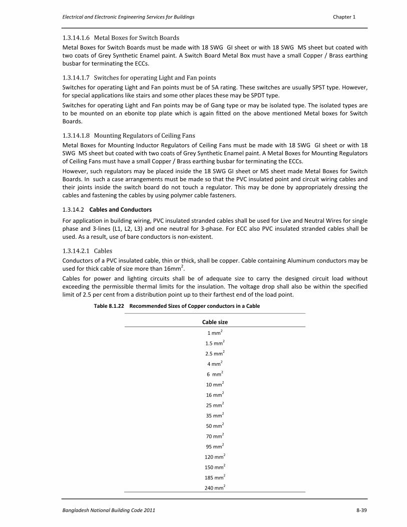
Electrical and Electronic Engineering Services for Buildings Chapter 1
Bangladesh National Building Code 2011 8‐39
1.3.14.1.6 Metal Boxes for Switch Boards Metal Boxes for Switch Boards must be made with 18 SWG GI sheet or with 18 SWG MS sheet but coated with two coats of Grey Synthetic Enamel paint. A Switch Board Metal Box must have a small Copper / Brass earthing busbar for terminating the ECCs.
1.3.14.1.7 Switches for operating Light and Fan points Switches for operating Light and Fan points must be of 5A rating. These switches are usually SPST type. However, for special applications like stairs and some other places these may be SPDT type.
Switches for operating Light and Fan points may be of Gang type or may be isolated type. The isolated types are to be mounted on an ebonite top plate which is again fitted on the above mentioned Metal boxes for Switch Boards.
1.3.14.1.8 Mounting Regulators of Ceiling Fans Metal Boxes for Mounting Inductor Regulators of Ceiling Fans must be made with 18 SWG GI sheet or with 18 SWG MS sheet but coated with two coats of Grey Synthetic Enamel paint. A Metal Boxes for Mounting Regulators of Ceiling Fans must have a small Copper / Brass earthing busbar for terminating the ECCs.
However, such regulators may be placed inside the 18 SWG GI sheet or MS sheet made Metal Boxes for Switch Boards. In such a case arrangements must be made so that the PVC insulated point and circuit wiring cables and their joints inside the switch board do not touch a regulator. This may be done by appropriately dressing the cables and fastening the cables by using polymer cable fasteners.
1.3.14.2 Cables and Conductors
For application in building wiring, PVC insulated stranded cables shall be used for Live and Neutral Wires for single phase and 3‐lines (L1, L2, L3) and one neutral for 3‐phase. For ECC also PVC insulated stranded cables shall be used. As a result, use of bare conductors is non‐existent.
1.3.14.2.1 Cables Conductors of a PVC insulated cable, thin or thick, shall be copper. Cable containing Aluminum conductors may be used for thick cable of size more than 16mm2.
Cables for power and lighting circuits shall be of adequate size to carry the designed circuit load without exceeding the permissible thermal limits for the insulation. The voltage drop shall also be within the specified limit of 2.5 per cent from a distribution point up to their farthest end of the load point.
Table 8.1.22 Recommended Sizes of Copper conductors in a Cable
Cable size
1 mm2
1.5 mm2
2.5 mm2
4 mm2
6 mm2
10 mm2
16 mm2
25 mm2
35 mm2
50 mm2
70 mm2
95 mm2
120 mm2
150 mm2
185 mm2
240 mm2
Part 8 Building Services
8‐40 Vol. 3
Cable size
300 mm2
400 mm2
500 mm2
630 mm2
800 mm2
1000 mm2
For final circuit/ sub‐circuit and for Light / fan point wiring the cable nominal cross‐section of the cable shall not
be less than 1.5 mm2 for copper conductors.
Standard copper conductor sizes of cables which should be used for Electrical Installations / Distribution in buildings are given below. Conductors of sizes other than the sizes listed below are not recommended.
1.3.14.2.2 Phase and neutral cables shall be of the same size In the wiring of the sub‐circuit/ circuit and all other circuits inside a building the Phase cable and the neutral cable shall be of the same size.
1.3.14.2.3 Flexible Cables / Flexible Cords
The minimum cross‐sectional area of conductors of flexible cables / flexible cords shall be 0.5 mm2 for copper conductors. Flexible cable or cords shall not be used as fixed wiring unless contained in an enclosure affording mechanical protection.
Flexible cables / flexible cords may be used for connections to portable equipment. For the purpose of this regulation an electric cooker of rated input exceeding 3 kW is not considered to be portable. The flexible cord shall be of sufficient length so as to avoid undue risk of damage to the outlet, cord or equipment and of being a hazard to personnel.
1.3.14.2.4 Treatment of Cable Ends / Cable Terminations All stranded conductors must be provided with cable sockets / cable lugs of appropriate size fitted using appropriate hand press tool or hand crimp tool or hydraulic press tool depending on the size of the cable. This is necessary for termination of the cable ends on bus‐bars.
1.3.14.2.5 Jointing of Cables in wiring Cable joints for the PVC insulated cables used in circuit wiring (thin cables) are to be made through porcelain/PVC connectors with PIB tape wound around the connector before placing the cable inside the box joint / pull box.
1.3.15 Conduits through the Building Expansion Joints Conduits shall not normally be allowed to cross expansion joints in a building. Where such crossing is found to be unavoidable, special care must be taken to ensure that the conduit runs and wiring are not in any way put to strain or are not damaged due to expansion/contraction of the building structure. In unavoidable situations PVC conduits through an oversize Flexible PVC conduits may be used with pull boxes on both sides of the expansion joints.
1.3.16 Types of Electrical Wiring for Exterior Lighting and other exterior purposes
1.3.16.1 Electrical Wiring for Garden Lighting
For garden lighting PVC insulated PVC sheathed underground cables shall be used. For protection purpose these may be drawn through PVC pipe of appropriate dimension so that adequate clearance remains for the ease of pulling. In general, no junction of cables shall be provided in underground level. However, in case of necessity, metal sleeve cable ferrule joints using Crimp Tool or hydraulic press and heat shrink insulated sleeve shall be used on top.
1.3.16.2 Electrical Wiring for Street Lighting
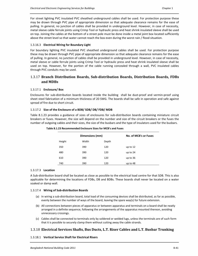
Electrical and Electronic Engineering Services for Buildings Chapter 1
Bangladesh National Building Code 2011 8‐41
For street lighting PVC insulated PVC sheathed underground cables shall be used. For protection purpose these may be drawn through PVC pipe of appropriate dimension so that adequate clearance remains for the ease of pulling. In general, no junction of cables shall be provided in underground level. However, in case of necessity, metal sleeve cable ferrule joints using Crimp Tool or hydraulic press and heat shrink insulated sleeve shall be used on top. Joining the cables at the bottom of a street pole must be done inside a metal joint box located sufficiently above the street level so that water cannot reach the box even during the worst rain / flood situation. 1.3.16.3 Electrical Wiring for Boundary Light
For boundary lighting PVC insulated PVC sheathed underground cables shall be used. For protection purpose these may be drawn through PVC pipe of appropriate dimension so that adequate clearance remains for the ease of pulling. In general, no junction of cables shall be provided in underground level. However, in case of necessity, metal sleeve or cable ferrule joints using Crimp Tool or hydraulic press and heat shrink insulated sleeve shall be used on top. However, for the portion of the cable running concealed through a wall, PVC insulated cables through PVC conduits may be used.
1.3.17 Branch Distribution Boards, Subdistribution Boards, Distribution Boards, FDBs and MDBs
1.3.17.1 Enclosure/ Box
Enclosures for sub‐distribution boards located inside the building shall be dust‐proof and vermin‐proof using sheet steel fabrication of a minimum thickness of 20 SWG. The boards shall be safe in operation and safe against spread of fire due to short circuit.
1.3.17.2 Size of the Enclosure of a BDB/ SDB/ DB/ FDB/ MDB
Table 8.1.23 provides a guidance of sizes of enclosures for sub‐distribution boards containing miniature circuit breakers or fuses. However, the size will depend on the number and size of the circuit breakers or the fuses the number of outgoing cables and their sizes, the size of the busbars and the type of insulators used for the busbars.
Table 8.1.23 Recommended Enclosure Sizes for MCB's and Fuses
Dimensions (mm) No. of MCB's or Fuses
Height Width Depth
350 390 120 up to 12
480 390 120 up to 24
610 390 120 up to 36
740 390 120 up to 48
1.3.17.3 Location
A Sub‐distribution board shall be located as close as possible to the electrical load centre for that SDB. This is also applicable for determining the locations of FDBs, DB and BDBs. These boards shall never be located on a water soaked or damp wall.
1.3.17.4 Wiring of Sub‐distribution Boards
(a) In wiring a sub‐distribution board, total load of the consuming devices shall be distributed, as far as possible, evenly between the number of ways of the board, leaving the spare way(s) for future extension.
(b) All connections between pieces of apparatus or between apparatus and terminals on a board shall be neatly arranged in a definite sequence, following the arrangements of the apparatus mounted thereon, avoiding unnecessary crossings.
(c) Cables shall be connected to terminals only by soldered or welded lugs, unless the terminals are of such form that it is possible to securely clamp them without cutting away the cable strands.
1.3.18 Electrical Services Shafts, Bus Ducts, L.T. Riser Cables and L.T. Busbar Trunking
1.3.18.1 Vertical Service Shaft for Electrical Risers
Part 8 Building Services
8‐42 Vol. 3
For buildings over six‐storey or 20 m high there shall, in general, be a minimum of one vertical electrical service
shaft of 200 mm x 400 mm size for every 1500 m2 floor area. The electrical service shaft shall exclusively be used for the following purposes:
Electric supply feeder cables or riser mains,
Busbar Trunking,
telephone cables,
Data Cables,
fire alarm cables,
CCTV cables,
Other signal cables,
Area fuse/circuit breakers,
Floor Distribution board / sub‐distribution boards for individual floors.
The construction of the floors of the duct area shall be constructed in such a way so that the empty space after putting the cables/ busar trunking / pipes / conduits in position the remaining open space is filled up with RCC slab(s) or any other non inflammable material so that fire or molten PVC can not fall from one floor to the next lower floor(s). For this purpose arrangements need to be made during the main floor casting.
Free and easy access to the electrical shaft room in each floor must be available for operation, maintenance and emergency shut downs.
Vertical cables other than electrical cables shall be placed at a sufficient distance from the nearest electrical cable. A vertical separating brick wall between electrical and non electrical wall is preferable.
Vertical Service Shaft for Electrical Risers as mentioned above must not be placed adjacent to the Sanitary Shafts. They should be placed at significant separation in order to ensure that the Vertical Service Shaft for Electrical Risers remains absolutely dry.
1.3.18.2 L.T. Riser Main Cables
For low rise building Riser Main Cables will serve to bring L.T. connection to the Floor Distribution Boards (FDBs) of each floor from the Main Distribution Board. For a 5 storied building or lesser having a floor space of less than 600 m2 in each floor the riser cables may be PVC insulated cables through PVC or GI pipes.
For bringing the riser main cables a common vertical wall and holes or slots in the floors must be given by the building construction people.
However, for larger floor area or for higher buildings PVC insulated PVC sheathed underground cables must be used with protection and spacing.
For more than 9 storied building Busbar preferably sandwiched copper Busbar. Trunking should be used for safety reasons.
PVC insulated PVC Sheathed underground cables must be used as Riser Main Cables. These cables shall be placed in or pulled through a PVC pipe of higher diameter so that the cable can be easily pulled through it. The PVC pipes must be fixed vertically in a straight line on the wall of the shaft using appropriate saddles. However, in some cases PVC insulated PVC Sheathed underground cables may be directly fixed on the wall using appropriate saddles with 37mm spacing between two adjacent cables. Sheet metal made Joint Boxes (with ebonite cover plates) must be placed at each floor tapping point.
The cable work shall be done neatly so that no suspended cables are seen around the place and no suspended flexible pipes are seen.
Each riser cable must have appropriate fuse or circuit breaker protection at the source busbur junction and also at the tap off point.
1.3.18.3 L.T. Busbar Trunking
For high rise buildings, LT (0.4KV TP&N) busbar trunking sytem is used instead of riser main cables to minimize space in the vertical electrical shaft, to minimize the risk of spreading of fire from one floor to another due to electrical short circuit in one of the cables or sparks, to have a neat distribution system. Most part of the Busbar Trunking are installed vertically. The horizontal portion of the Busbar Trunking usually connects the vertical portion with the Substation LT panel.
Electrical and Electronic Engineering Services for Buildings Chapter 1
Bangladesh National Building Code 2011 8‐43
a) Busbar Trunking are specially useful to minimize voltage drop on account of high amperage intermittent loads. The conductors supported by insulators inside the busbar trunking shall be copper of solid rectangular cross‐section. The copper bars are insulated. A busbar trunking system shall be laid with minimum number of bends for distribution system. Typical rating of feeder busbar trunking for 3‐phase‐ 3‐wire or 3‐phase‐ 4‐wire system shall range from 200 amperes to 3000 amperes although lower amperes are not impossible.
b) Horizontal busbar trunking of suitable size may be provided along the roads for a group of buildings to be fed by a single substation but with heavy weather protection and covered with appropriate weather resistant water proof material. Extreme care need to be taken in these cases for protection against moisture, water and outside weather.
c) Busbar Trunking must not be placed in places which is even slightly exposed to weather/ moisture/ spray or sprinkle of water.
1.3.18.4 L.T. Busducts
In certain applications, especially in factory lighting and factory power distribution of large area factories Busducts are used. In most cases, these Busducts are suspended from ceiling. Busducts offer safe, reliable, neat distribution system in these cases. The choice will depend on the floor area, type of machineries, type of jobs and other factors.
Appropriate circuit protection using adequate number of circuit breakers of appropriate rating are needed. In most cases these busducts are horizontally mounted / suspended. The busbars shall be copper. The rating shall depend on the current on each segment and the current carried by each segment.
1.3.19 L. T. Main Incoming Cable and Service Connection
1.3.19.1 Overhead service connection to a building shall be achieved with PVC insulated Cables with GI support wire (similar to cateneray) or catenary wire (mainly for single phase consumers). The overhead service connection shall be led into buildings via roof poles or service masts made of GI pipe at least 38 mm in diameter having a goose neck bend at the top and installed on the outer wall. This is one choice. The alternative is to have underground cable connection.
1.3.19.2 Underground Cables for using as Main Incoming Cable
Underground PVC insulated PVC sheathed water proof cables shall be placed in underground cable trench or pulled through a PVC pipe of higher diameter placed in a cable trench so that the cable can be easily pulled through it. PVC insulated stranded annealed copper ECC cables matching with the main cable size shall run along the Main incoming cable with termination at the earthing busbar at both end.
Each of the PVC pipes must have 18 SWG GI pull wires placed during laying of the pipes for pulling the cables later.
1.3.19.3 Jointing of underground Cables and Main Incoming Cables
For main incoming thick underground cables joints are strongly discouraged and should be avoided as far as possible.
However, for unavoidable cases joints must be made through sleeve or ferrule of appropriately matched size fitted with hydraulic press following neat processing of the cable ends. Appropriate fusible heat shrink cover must be used over such junction.
For thick cables running through conduits as vertical risers, these joints must be put inside metal joint / pull boxes with covers.
1.3.19.4 Flame proof enclosure of Incoming cables and riser cables
Special forms of construction, such as flame proof enclosures, shall be adopted where risk of fire or explosion exists near a place where thick incoming cable or riser cables are placed.
1.3.19.5 Underground service cables shall be laid in conformity with the requirements of Sec 1.3.29 titled “Laying of LT underground Cables”.
Part 8 Building Services
8‐44 Vol. 3
1.3.19.6 Power and telecommunication or antenna cables must be laid separately maintaining sufficient distance.
1.3.19.7 Fire alarm and emergency lighting circuits shall be segregated from all other cables and from each other in accordance with BS 5839 and BS 5266. Telecommunication circuits shall be segregated in accordance with BS 6701 as appropriate.
1.3.19.8 Proximity to non‐electrical services
Where a wiring system is located in close proximity to a non electrical service both the following conditions shall be met:
the wiring system shall be suitably protected against the hazards likely to arise from the presence of the other service in normal use, and appropriate protection against indirect contact shall be taken.
1.3.19.9 A wiring system shall not be installed in the vicinity of a service which produces heat, smoke or fume likely to be detrimental to the wiring, unless protected from harmful effects by shielding arranged so as not to affect the dissipation of heat from the wiring.
1.3.19.10 Where a wiring system is routed near a service liable to cause condensation (such as water, steam or gas services) precautions shall be taken to protect the wiring system from deleterious effects.
1.3.19.11 No cable shall be run in a lift (or hoist) shaft unless it forms part of the lift installation as defined in BS 5655.
1.3.20 Design for Electrical Wiring Design of Electrical wiring must be done following the codes provided in this document. Detailed Design drawings must be prepared by a designer for complete execution of the electrical works mentioned in this document and any other new items arising because of the evolution of new technologies in the near future.
Typically, there must be conduit layout drawing(s) indicating the conduit layouts, the locations of the switch boards, locations of the sockets, locations of the BDBs, locations of the SDBs, locations of the DBs, locations of the FDBs, location of the MDB, location of the Main incoming cable.
A distribution diagram of the BDBs, SDBs upto MDBs as applicable indicating the ampere rating of the incoming MCB / MCCB, interlinking cable sizes and the ECCs must be presented.
Detailed Circuit Diagrams of the circuits and the BDBs, SDBs… MDBs as applicable must be presented.
Detailed drawings of earthing and earth inspection pits and any other complicated parts must be presented. The contractor shall prepare as built drawings after completing a project.
1.3.20.1 Design for Electrical Wiring in Bedrooms and Drawing Rooms
The location of a switch board must be near the entrance door of a bedroom like any other room. The location of the wall mounted light fittings must be chosen based on the possible locations of furniture which is also needed in other rooms. Sufficient number of 3‐pin 13 A switched shuttered flat pin sockets must be provided in a bed room.
The same ideas are applicable for a Living room.
Design must be made in such a way that sufficient clearance (space) is left inside the concealed conduits (i) for the ease of pulling the cables and also for adding few more cables in case of necessity during future modification.
For Bedrooms and Drawing Rooms the Light + Fan sub circuits for shall not be of more than 5A rating.
Generally, Single core PVC insulated Stranded Electrolytic Annealed Copper Cables shall be used for wiring by using the concealed wiring technique or the other two methods mentioned in the wiring section.
1.3.20.2 Design for Electrical Wiring in a Kitchen especially providing 3 pin sockets near Kitchen sink (the clearance).
The sensitive item in a kitchen is placing 3‐pin 13 A switched shuttered flat pin sockets on wall of the kitchen side table near the wall. Good distance must be maintained between the kitchen water tap and the socket. The Socket for the Refrigerator (if any) shall also be a 3‐pin 13 A switched shuttered flat pin socket, and may be placed at the
Electrical and Electronic Engineering Services for Buildings Chapter 1
Bangladesh National Building Code 2011 8‐45
same level as the other socket. For the ease of operation a 3‐pin 13 A switched shuttered flat pin socket for this purpose may be placed at the bottom level height of a switch board provided this is acceptable in terms of aesthetics. For Kitchens, the Light + Fan sub circuits for shall not be of more than 5A rating.
1.3.20.3 Switches for Toilets and Bath Rooms
Switches for toilet lights and toilet ventilating fans must be placed outside the toilets adjacent to the entrance door but must not be placed inside the Toilet. The same rule should be followed for Bath Rooms. Using ceiling mounted chord switch at the entrance path of the door of a toilet is a good idea for small toilets attached to bed rooms. Ceiling mounted chord switches may be used with a chord suspended from the ceiling near the opening of the door
1.3.20.4 Design for Electrical Wiring in Office Rooms The location of a switch board must be near the entrance door of an office room. The location of the light fittings must be chosen based on the possible locations of work table, furniture. Sufficient number of 3‐pin 13 A switched shuttered flat pin sockets must be provided in each office room. In this regard special consideration need to be given on the possible location of computers and other office equipment.
Sufficient conduits and cables must be left for future modification as often rearrangement of tables need to be made.
Generally, Single core PVC insulated Stranded Electrolytic Annealed Copper Cables shall be used for wiring by using the concealed wiring technique or the other two methods mentioned in the wiring section.
In case of special requirements, PVC insulated PVC sheathed Stranded Electrolytic Annealed Copper Cables may be used for wiring through conduits or other methods.
For Offices the sub circuits for shall not be of more than 5A rating.
1.3.21 Temporary Electrical Connection for a Building Construction Site Temporary connections are needed for a building construction site. A Fuse Distribution board containing incoming cut out fuse, outgoing cutout fuses plus bus bars or a Distribution boards containing in coming circuit breakers, outgoing circuit breakers plus bus bars of appropriate rating must be installed for such connections. Such boards shall be installed in a dry place so that rain water or waters coming from a construction zone cannot reach such boards.
1.3.22 Temporary Electrical Connection for an outdoor concert Temporary connections are needed for an outdoor concert stage for special lighting, for various display systems, for high power audio systems. A Fuse Distribution board containing incoming cut out fuse, outgoing cutout fuses plus bus bars or a Distribution board containing in coming circuit breakers, outgoing circuit breakers plus bus bars of appropriate rating must be installed for such connections. Such boards shall be installed in a dry place and shall be mounted at a safe height above ground so that rain water or waters coming from anywhere cannot reach such boards. Such boards shall not be installed near flammable materials.
Cables of appropriate types and appropriate ratings must be used for such applications.
Appropriate type of sockets, preferably flat 3‐pin switched shuttered 13A sockets should be used for distribution.
1.3.23 11KV/ 0.4 KV Electrical Substation in a Building
1.3.23.1 General
According to the rule of the distribution companies of Bangladesh, 11KV/ 0.4KV Electrical substations shall be required for a building if the load requirement of the building exceeds 50KW. In most cases, substations are required for Multi‐storied residential, Multi‐storied Commercial buildings, Multi‐storied Office building and Industries.
To determine the rating of the substation required, a load factor of at least 80% shall be applied to the estimated load of the building. The future expansion requirements should definitely be taken into consideration.
1.3.23.2 Location of an Electrical Substation

Part 8 Building Services
8‐46 Vol. 3
In a multi‐storied building, the substation shall preferably be installed on the lowest floor level, but direct access from the street for installation or removal of the equipment shall be provided. The floor level of the substation or switch room shall be above the highest flood level of the locality. Suitable arrangements should exist to prevent the entrance of storm or flood water into the substation area.
The location of a substation will depend on (i) the feed point of the 11 KV Supply Authority line and (ii) the location of the LT vertical riser cables.
It is preferable to locate the air‐conditioning plant room (if any) adjacent to the electrical substation in such a way that the distance from the controlling switchboard of the air‐conditioning plant rooms and corresponding switches in the electrical substation are kept minimum.
In case of a building complex, or a group of buildings belonging to the same organization, the substation should preferably be located in a separate building and should be adjacent to the generator room, if any. Location of substation in the basement floor and on the floors above ground floor level (GFL) preferably be avoided. If Sub‐Station it to be installed on the basement floor or the floors above ground floor level (GFL) special safety measures is to be taken by the user or owner. Measures are as follows:
(i) No objection certificate stating the Sub‐Station safe by the Fire Service and Civil Defense Department.
(ii) Certification of the building consultant stating safe, Proper ventilation, Easy entrance and exit and safe load bearing capacity of the floors above the ground floor level (GFL).
(iii) Proper undertaking of the Sub‐Station user or owner as the case may be, Stating safety and liability will be ensured by them.
In case the electric substation has to be located within the main building itself for unavoidable reasons, it should be located on ground floor or Basement floor or the floors above the ground floor (GFL) with easy access from outside.
1.3.23.3 Height, Area, Floor Level and other requirements of a Substation Room
a) The minimum height of a substation room should be 3.0m to 3.6m depending upon the size of the transformer.
b) The minimum area required for substation and transformer room for different capacities are given in Table 8.1.24.
c) For transformers having large oil content (more than 2000 litres), soak pits are to be provided.
The areas given in Table 8.1.24 hold good if they are provided with windows and independent access doors in accordance with local regulations.
All the rooms shall have significant ventilation. Special care should be taken to ventilate the transformer rooms and where necessary louvers at lower level and exhaust fans at higher level shall be provided at suitable locations in such a way that cross ventilation is maintained. Fans should be provided so that the transformer gets air supply from the fans.
The floor level of the substation should be high. Arrangement shall be made to prevent storm water entering the transformer and switch rooms through the soak pits, if floor level of the substation is low.
Sub‐Station of higher voltage may also be considered to the basement floor having proper & safe building design.
Table 8.1.24 Area Required for Transformer and Recommended Minimum Area for Substation of Different Capacities
Capacity of
Transformer
(kVA)
Transformer
Area
(m2)
Total Substation Area (with HT, LT Panels & Transformer Room
but without Generators)
(m2)
1x150 12 45
1x250 13 48
2x250 26 100
1x400 13 48
2x400 30 100
3x400 40 135
Electrical and Electronic Engineering Services for Buildings Chapter 1
Bangladesh National Building Code 2011 8‐47
2x630 26 100
3x630 40 190
2x1000 40 180
3x1000 45 220
1.3.23.4 11KV / 0.4KV Distribution Transformer for the Substation of a Building
An 11KV / 0.4KV indoor distribution Transformer is a major part of an indoor substation . These Substations may be installed inside the building itself or may be housed in a separate building adjacent to the building.
For small to moderate power rating up to 2MW two types of indoor transformers have been widely used in recent years. These are (i) Oil Type Natural Cooled transformer and (ii) Cast Resin Dry Type Natural Cooled transformers.
In most cases Oil Type Natural Cooled transformer may be used for substations if adequate space is available to accommodate the transformer.
Cast Resin Dry Type Natural Cooled transformers should be used (i) in places where stringent protection against spread of fire is needed and (ii) in places where space saving is of utmost importance.
1.3.23.4.1 Choice of Oil type or Dry type transformers Dry type transformer should be installed where risk of spreading of fire is high and where flammable materials are to be kept around the substation.
For Hospital buildings, Multistoried Shopping Centers Dry type transformers should be used to for minimizing fire risks.
An Industrial buildings containing inflammable materials, Chemical and having the substation in the same building Dry type transformers should be used for minimizing fire risks.
1.3.23.5 Type of connection between a Substation Transformer and its LT panel
Connection between a Substation Transformer and its LT panel can be established a) by using NYY underground LT Cables or b) by using Ceiling Suspended Busbar Trunking. For small size transformers the first method should be used although there is no restriction in using the second method. However, for big substations the second method is safer and at the same time gives a neat solution.
1.3.23.6 Ventilation of a Substation
In an Electrical Substation significant amount of forced ventilation is very much needed apart from natural ventilation. Exhaust Fans (minimum 18” dia) must be provided in sufficient numbers on all sides of the substation above the lintel level. Grill fitted Windows having window panes must be provided on all sides for natural ventilation. The windows must have sun sheds to ensure that no rain water can come inside the substation.
If due to space constraint or due to any other difficulties, sufficient number of windows and ventilating fans cannot be installed, high velocity forced ventilation using ducts must be provided.
1.3.23.7 Layout of a Substation
In general, the Substation HT to LT Transformer shall be placed in one corner of the room so that the HT side remains away from the passage of the persons.
The HT Metering panel shall be located near the exterior of the substation room near the exit gate and also shall be convenient for the HT cable entry.
The HT Panel shall be located near the exterior, just after or adjacent to the HT panel.
LT Panel shall remain at a sufficient distance from the Transformer but not too far away from the Transformer. On the other hand, the location of the LT panel should such that the riser main cable can have their way upward or outward within very short distance.
In allocating the areas within a substation, it is to be noted that the flow of electric power is from supply company network to HT room, then to transformer and finally to the low voltage switchgear room. The layout of the rooms shall be in accordance with this flow.
All the rooms shall have significant ventilation. Special care should be taken to ventilate the transformer rooms and where necessary louvres at lower level and exhaust fans at higher level shall be provided at suitable locations
Part 8 Building Services
8‐48 Vol. 3
in such a way that cross ventilation is maintained. Ceiling fans must be provided so that the transformer gets air supply from the ceiling fans.
1.3.24 Standby Power Supply
1.3.24.1 Provision for Standby Power Supply
Provision should be made for standby power supply, in buildings, where interruption of electrical power supply would cause significant discomfort, result in interruption of activities, major production loss, cause hazard to life and property and cause panic. The Standby Power Supply may be a Petrol Engine or Diesel Engine or Gas Engine Generator or an IPS or a UPS.
1.3.24.2 Capacity of a Standby Generating Set
The capacity of standby generating set shall be chosen on the basis of essential light load, essential air‐conditioning load, essential equipment load and essential services load, essential lift (s), one or all water pumps and other loads required as essential load. Table 8.1.25 shows minimum generator room area requirements for different sizes of generators.
1.3.24.3 The Generator Room
The generating set should preferably be housed in the substation building or should be placed adjacent to the substation room to enable transfer of electrical load (Change over) with negligible voltage drop as well as to avoid transfer of vibration and noise to the main building. The generator room should have significant amount of ventilation and fitted with a number of ceiling fans. Appropriate type and number of fire fighting equipment must be installed inside the generator room. The generator engine exhaust should be appropriately taken out of the building and should preferably be taken out through any other side except South. The generator Oil tank should be place away from the control panel side. In case of gas engine generator extra precaution must be taken regarding ventilation, leakage to prevent explosion.
1.3.24.4 Changeover Switch of a Standby Generator
A standby generator, if needed, is to be connected at the supply input point after the Energy meter and after the Main Incoming Switch or the Main Incoming Circuit Breaker, but through a Changeover Switch of appropriate rating. The rating of such a switch shall be at least 1.25 times the rating of the Main Incoming Circuit Breaker. The Changeover Switch shall be of such a type so that when moved to the mains position, there is no chance that the generator will be connected and vice versa.
The Changeover Switch may be manual type with knife switch type switching or may be automatic type with magnetic contactors. In both the cases the Changeover Switch shall be properly made so that there is no chance of loose connection or spark.
The wiring for this purpose shall be made following the standard practices mentioned under the heading of wiring using cables of appropriate size.
Table 8.1.25 Area Requirements for Standby Generator Room
Capacity
(kW)
Area
(m2)
1x25 20
1x48 24
1x100 30
1x150 36
1x300 48
1x500 56
1.3.24.5 Installation of an IPS or a UPS
For safety purpose size of a UPS should be kept as small as possible.
For the installation of a 200 – 600 VA IPS a 5A circuit must be made with the light points and fan points of different rooms to be brought under the control of the IPS. This circuit must have 3A Fuse protection using fuse
Electrical and Electronic Engineering Services for Buildings Chapter 1
Bangladesh National Building Code 2011 8‐49
cutout box. Wiring and connection has to be made following the wiring rules given in the wiring sections of this document. Cables of appropriate size must be used for wiring.
For the installation of a 600 – 700 VA IPS a 5A circuit must be made with the light points and fan points of different rooms to be brought under the control of the IPS. This circuit must have 5A Fuse protection or 5A circuit breaker protection. Wiring and connection has to be made following the wiring rules given in the wiring sections of this document. Cables of appropriate size must be used for wiring.
For the installation of a IPS of higher capacity, a BDB with multiple outgoing circuits each not exceeding 5A shall be used with cutout ‐ fuse protection at both incoming and outgoing sides. Cables of appropriate size must be used for wiring of each circuit.
Battery maintenance (checking water level, temperature rise and the condition of the terminals) should be done at least every 15 days. Connection of the Battery terminals should be made properly and checked periodically for loose connection and deposition of sulphate. Battery of an IPS must be kept in a safe place so that short circuit between the battery terminals does not occur. Inflammable materials must not be kept in the vicinity of the IPS or battery.
Safety issue must be taken into consideration in placing an IPS in a room.
Same points apply for the installation of an UPS.
1.3.24.6 Installation of a Solar Photovoltaic System on top of a Building
Building should be provided with solar photovoltaic system. For installation Solar Photovoltaic system necessary precaution need to be taken. Separate wiring and protection system may also be ensured.
Installation of solar water heaters on the roof tops of the residential and commercial buildings: The buildings or apartments where hot water will be required and for that purpose installation of geezers or electric kettles should be considered and use of solar water heaters instead of electric and gas water heaters should be made mandatory. Flat plate heat collectors or vacuum tube solar water heaters of various capacities are available in the market. These devices are relatively cheap an environment friendly.
The integral parts of a conventional Solar Photovoltaic System are
a) Solar Photovoltaic Panel(s)
b) Battery Charge Controller
c) Inverter
d) Cables between the Solar Photovoltaic Panel(s) and the Battery Charge Controller
e) Cables between the Battery and the Battery Charge Controller
f) Cables between the Inverter and the Distribution Board (DB/ SDB/BDB)
g) Other cables and accessories.
For the installation of a Solar Photovoltaic System of higher capacity, a DB with multiple outgoing circuits each not exceeding 5A shall be used with cutout ‐ fuse protection at both incoming and outgoing side. Copper Cables of appropriate size must be used for wiring of each circuit.
Battery maintenance (checking water level, temperature rise and the condition of the terminals) should be done at least every 15 days. Connection of the Battery terminals should be made properly and checked periodically for loose connection and deposition of Sulphate.
Batteries of a Solar Photovoltaic System must be kept in a safe place so that short circuit between the battery terminals does not occur. Inflammable materials must not be kept in the vicinity of the IPS or battery. In most cases for roof top Solar Panels, the battery room shall be placed inside a roof top room with adequate natural ventilation and forced cooling using ceiling fans. Because of the roof top location of the Solar panels, the room temperature is expected to be higher.
Safety issue must be taken into consideration in placing the batteries of a Solar Photovoltaic System .
For a residential flat system building, one or two circuits for each flat shall come from the DB of the Photo‐Voltaic Source at roof top to each flat depending on the requirement. Connection to load in each flat will be done through a changeover switch for each circuit.
For a Commercial/ Office Building, one or two circuits for each office /Office area shall come from the DB of the Photo‐Voltaic Source at roof top to each flat depending on the requirement. Connection to load in each flat will be done through a changeover switch for each circuit.
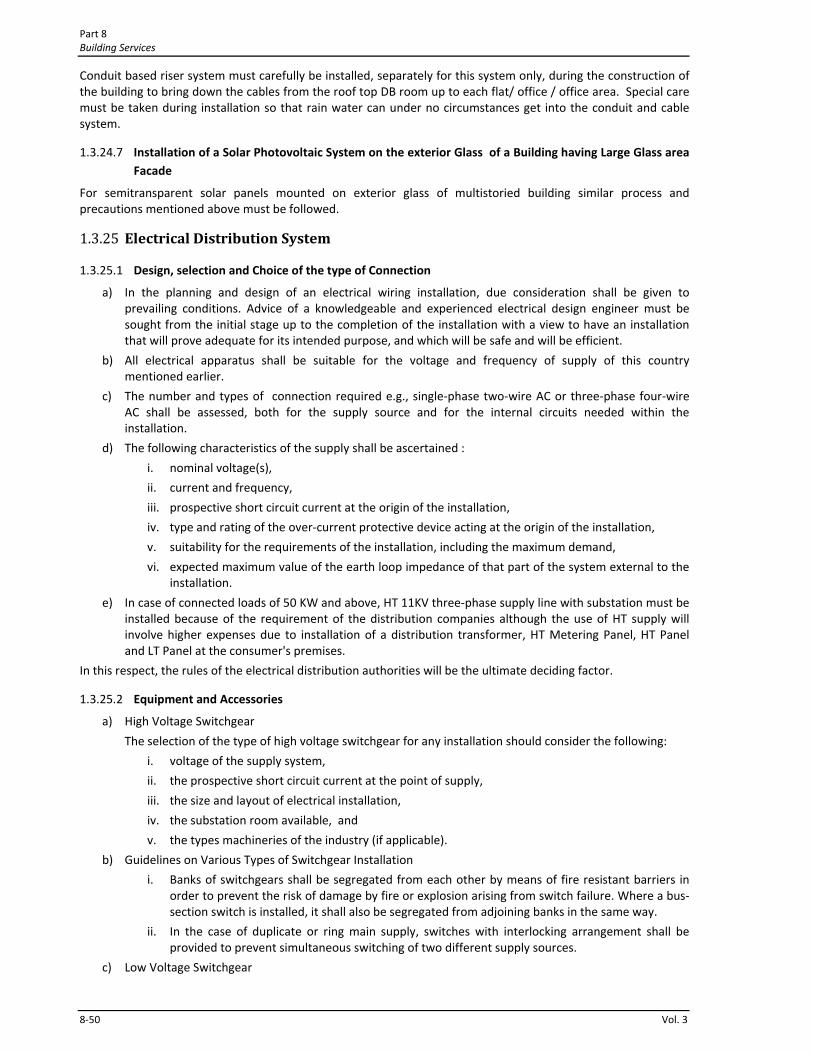
Part 8 Building Services
8‐50 Vol. 3
Conduit based riser system must carefully be installed, separately for this system only, during the construction of the building to bring down the cables from the roof top DB room up to each flat/ office / office area. Special care must be taken during installation so that rain water can under no circumstances get into the conduit and cable system.
1.3.24.7 Installation of a Solar Photovoltaic System on the exterior Glass of a Building having Large Glass area Facade
For semitransparent solar panels mounted on exterior glass of multistoried building similar process and precautions mentioned above must be followed.
1.3.25 Electrical Distribution System
1.3.25.1 Design, selection and Choice of the type of Connection
a) In the planning and design of an electrical wiring installation, due consideration shall be given to prevailing conditions. Advice of a knowledgeable and experienced electrical design engineer must be sought from the initial stage up to the completion of the installation with a view to have an installation that will prove adequate for its intended purpose, and which will be safe and will be efficient.
b) All electrical apparatus shall be suitable for the voltage and frequency of supply of this country mentioned earlier.
c) The number and types of connection required e.g., single‐phase two‐wire AC or three‐phase four‐wire AC shall be assessed, both for the supply source and for the internal circuits needed within the installation.
d) The following characteristics of the supply shall be ascertained :
i. nominal voltage(s),
ii. current and frequency,
iii. prospective short circuit current at the origin of the installation,
iv. type and rating of the over‐current protective device acting at the origin of the installation,
v. suitability for the requirements of the installation, including the maximum demand,
vi. expected maximum value of the earth loop impedance of that part of the system external to the installation.
e) In case of connected loads of 50 KW and above, HT 11KV three‐phase supply line with substation must be installed because of the requirement of the distribution companies although the use of HT supply will involve higher expenses due to installation of a distribution transformer, HT Metering Panel, HT Panel and LT Panel at the consumer's premises.
In this respect, the rules of the electrical distribution authorities will be the ultimate deciding factor.
1.3.25.2 Equipment and Accessories
a) High Voltage Switchgear
The selection of the type of high voltage switchgear for any installation should consider the following:
i. voltage of the supply system,
ii. the prospective short circuit current at the point of supply,
iii. the size and layout of electrical installation,
iv. the substation room available, and
v. the types machineries of the industry (if applicable).
b) Guidelines on Various Types of Switchgear Installation
i. Banks of switchgears shall be segregated from each other by means of fire resistant barriers in order to prevent the risk of damage by fire or explosion arising from switch failure. Where a bus‐section switch is installed, it shall also be segregated from adjoining banks in the same way.
ii. In the case of duplicate or ring main supply, switches with interlocking arrangement shall be provided to prevent simultaneous switching of two different supply sources.
c) Low Voltage Switchgear

Electrical and Electronic Engineering Services for Buildings Chapter 1
Bangladesh National Building Code 2011 8‐51
i. Switchgear and fusegear must have adequate breaking capacity in relation to the capacity of the transformers.
ii. Isolation and protection of outgoing circuits forming the main distribution system may be effected by means of circuit breakers, or fuses or switch fuse units mounted on the main switchboard. The choice between alternative types of equipment will take the following points into consideration:
iii. In certain installations supplied with electric power from remote transformer substations, it may be necessary to protect main circuits with circuit breakers operated by earth leakage trips, in order to ensure effective earth fault protection.
iv. Where large electric motors, furnaces or other heavy electrical equipment are installed, the main circuits shall be protected by metal clad circuit breakers or conductors fitted with suitable instantaneous and time delay overcurrent devices together with earth leakage and backup protection where necessary.
v. In installations other than those mentioned above or where overloading of circuits may be considered unlikely, HRC type fuses will normally afford adequate protection for main circuits separately as required; the fuses shall be mounted in switch fuse units or with switches forming part of the main switch boards.
vi. Where it is necessary to provide suitable connection for power factor improvement capacitors at the substation bus, suitable capacitors shall be selected in consultation with the capacitor and switchgear manufacturer and necessary switchgear/feeder circuit breaker shall be provided for controlling the capacitor bank(s).
1.3.26 Transformers a) Where two or more transformers are to be installed in a substation to supply an LT distribution system,
the distribution system shall be divided into separate sections each of which shall normally be fed from one transformer only unless the LT switchgear has the requisite short circuit capacity.
b) Provision may, however, be made to interconnect Busbar sections through bus couplers to cater for the failure or disconnection of one transformer which need to be executed with much care using locking system.
c) The transformers, which at any time operate in parallel, shall be so selected as to share the load in proportion to their respective ratings. Appropriate protection must be provided and appropriate arrangements need to be made.
d) When a step‐up transformer is used, a linked switch shall be provided for disconnecting the transformer from all poles of the supply, including the neutral conductor.
1.3.27 Precautions regarding Rotating Machines a) All equipment including cables, of every circuit carrying the starting, accelerating and load currents of
motors, shall be suitable for a current at least equal to the full load current rating of the motor. When the motor is intended for intermittent duty and frequent stopping and starting, account shall be taken of any cumulative effects of the starting periods upon the temperature rise of the equipment of the circuit.
b) The rating of circuits supplying the rotors of slip ring or commutator of a motor or an induction motor shall be suitable for both the starting and loaded conditions.
c) Every electric motor having a rating exceeding 0.376 kW shall be provided with control equipment incorporating means of protection against overcurrent.
d) Every motor shall be provided with means to prevent automatic restarting after a stoppage due to drop in voltage or failure. This requirement does not apply to any special cases where the failure of the motor to start after a brief interruption of the supply would be likely to cause greater danger. It also does not preclude arrangements for starting a motor at intervals by an automatic control device, where other adequate precautions are taken against danger from unexpected restarting.
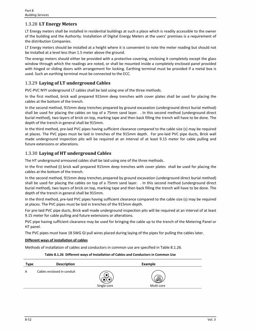
Part 8 Building Services
8‐52 Vol. 3
1.3.28 LT Energy Meters LT Energy meters shall be installed in residential buildings at such a place which is readily accessible to the owner of the building and the Authority. Installation of Digital Energy Meters at the users’ premises is a requirement of the distribution Companies.
LT Energy meters should be installed at a height where it is convenient to note the meter reading but should not be installed at a level less than 1.5 meter above the ground.
The energy meters should either be provided with a protective covering, enclosing it completely except the glass window through which the readings are noted, or shall be mounted inside a completely enclosed panel provided with hinged or sliding doors with arrangement for locking. Earthing terminal must be provided if a metal box is used. Such an earthing terminal must be connected to the ECC.
1.3.29 Laying of LT underground Cables PVC‐PVC NYY underground LT cables shall be laid using one of the three methods.
In the first method, brick wall prepared 915mm deep trenches with cover plates shall be used for placing the cables at the bottom of the trench.
In the second method, 915mm deep trenches prepared by ground excavation (underground direct burial method) shall be used for placing the cables on top of a 75mm sand layer. . In this second method (underground direct burial method), two layers of brick on top, marking tape and then back filling the trench will have to be done. The depth of the trench in general shall be 915mm.
In the third method, pre‐laid PVC pipes having sufficient clearance compared to the cable size (s) may be required at places. The PVC pipes must be laid in trenches of the 915mm depth. For pre‐laid PVC pipe ducts, Brick wall made underground inspection pits will be required at an interval of at least 9.15 meter for cable pulling and future extensions or alterations.
1.3.30 Laying of HT underground Cables The HT underground armoured cables shall be laid using one of the three methods.
In the first method (i) brick wall prepared 915mm deep trenches with cover plates shall be used for placing the cables at the bottom of the trench.
In the second method, 915mm deep trenches prepared by ground excavation (underground direct burial method) shall be used for placing the cables on top of a 75mm sand layer. . In this second method (underground direct burial method), two layers of brick on top, marking tape and then back filling the trench will have to be done. The depth of the trench in general shall be 915mm.
In the third method, pre‐laid PVC pipes having sufficient clearance compared to the cable size (s) may be required at places. The PVC pipes must be laid in trenches of the 915mm depth.
For pre‐laid PVC pipe ducts, Brick wall made underground inspection pits will be required at an interval of at least 9.15 meter for cable pulling and future extensions or alterations.
PVC pipe having sufficient clearance may be used for bringing the cable up to the trench of the Metering Panel or HT panel.
The PVC pipes must have 18 SWG GI pull wires placed during laying of the pipes for pulling the cables later.
Different ways of installation of cables
Methods of installation of cables and conductors in common use are specified in Table 8.1.26.
Table 8.1.26 Different ways of Installation of Cables and Conductors in Common Use
Type Description Example
A Cables enclosed in conduit
Single‐core
Multi‐core
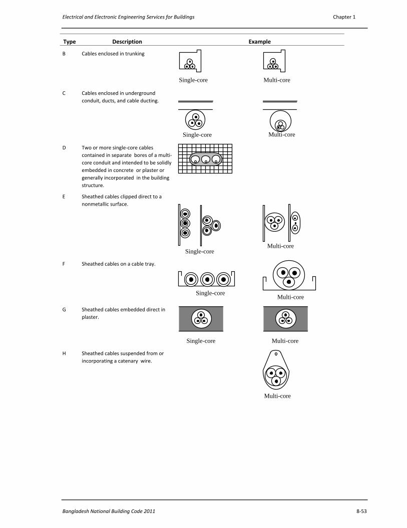
Electrical and Electronic Engineering Services for Buildings Chapter 1
Bangladesh National Building Code 2011 8‐53
Type Description Example
B Cables enclosed in trunking
Single-core Multi-core
C Cables enclosed in underground conduit, ducts, and cable ducting.
Single-core
Multi-core
D Two or more single‐core cables contained in separate bores of a multi‐core conduit and intended to be solidly embedded in concrete or plaster or generally incorporated in the building structure.
E Sheathed cables clipped direct to a nonmetallic surface.
Single-core
Multi-core
F Sheathed cables on a cable tray.
Single-core Multi-core
G Sheathed cables embedded direct in plaster.
Single-core Multi-core
H Sheathed cables suspended from or incorporating a catenary wire.
Multi-core
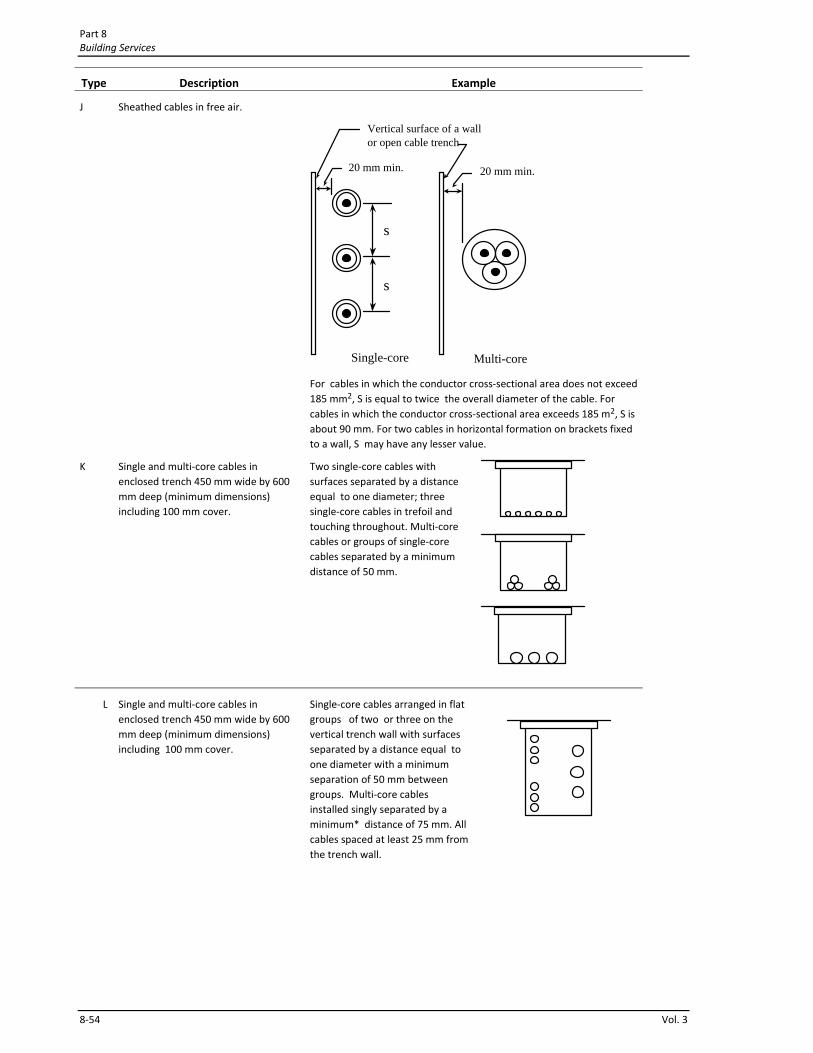
Part 8 Building Services
8‐54 Vol. 3
Type Description Example
J Sheathed cables in free air.
Single-core
20 mm min.
s
s
Multi-core
20 mm min.
Vertical surface of a wall or open cable trench
For cables in which the conductor cross‐sectional area does not exceed 185 mm2, S is equal to twice the overall diameter of the cable. For cables in which the conductor cross‐sectional area exceeds 185 m2, S is about 90 mm. For two cables in horizontal formation on brackets fixed to a wall, S may have any lesser value.
K Single and multi‐core cables in enclosed trench 450 mm wide by 600 mm deep (minimum dimensions) including 100 mm cover.
Two single‐core cables with surfaces separated by a distance equal to one diameter; three single‐core cables in trefoil and touching throughout. Multi‐core cables or groups of single‐core cables separated by a minimum distance of 50 mm.
L Single and multi‐core cables in enclosed trench 450 mm wide by 600 mm deep (minimum dimensions) including 100 mm cover.
Single‐core cables arranged in flat groups of two or three on the vertical trench wall with surfaces separated by a distance equal to one diameter with a minimum separation of 50 mm between groups. Multi‐core cables installed singly separated by a minimum* distance of 75 mm. All cables spaced at least 25 mm from the trench wall.
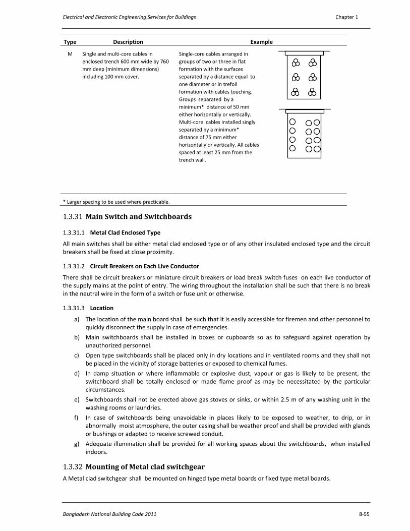
Electrical and Electronic Engineering Services for Buildings Chapter 1
Bangladesh National Building Code 2011 8‐55
Type Description Example
M Single and multi‐core cables in enclosed trench 600 mm wide by 760 mm deep (minimum dimensions) including 100 mm cover.
Single‐core cables arranged in groups of two or three in flat formation with the surfaces separated by a distance equal to one diameter or in trefoil formation with cables touching. Groups separated by a minimum* distance of 50 mm either horizontally or vertically. Multi‐core cables installed singly separated by a minimum* distance of 75 mm either horizontally or vertically. All cables spaced at least 25 mm from the trench wall.
* Larger spacing to be used where practicable.
1.3.31 Main Switch and Switchboards
1.3.31.1 Metal Clad Enclosed Type
All main switches shall be either metal clad enclosed type or of any other insulated enclosed type and the circuit breakers shall be fixed at close proximity.
1.3.31.2 Circuit Breakers on Each Live Conductor
There shall be circuit breakers or miniature circuit breakers or load break switch fuses on each live conductor of the supply mains at the point of entry. The wiring throughout the installation shall be such that there is no break in the neutral wire in the form of a switch or fuse unit or otherwise.
1.3.31.3 Location
a) The location of the main board shall be such that it is easily accessible for firemen and other personnel to quickly disconnect the supply in case of emergencies.
b) Main switchboards shall be installed in boxes or cupboards so as to safeguard against operation by unauthorized personnel.
c) Open type switchboards shall be placed only in dry locations and in ventilated rooms and they shall not be placed in the vicinity of storage batteries or exposed to chemical fumes.
d) In damp situation or where inflammable or explosive dust, vapour or gas is likely to be present, the switchboard shall be totally enclosed or made flame proof as may be necessitated by the particular circumstances.
e) Switchboards shall not be erected above gas stoves or sinks, or within 2.5 m of any washing unit in the washing rooms or laundries.
f) In case of switchboards being unavoidable in places likely to be exposed to weather, to drip, or in abnormally moist atmosphere, the outer casing shall be weather proof and shall be provided with glands or bushings or adapted to receive screwed conduit.
g) Adequate illumination shall be provided for all working spaces about the switchboards, when installed indoors.
1.3.32 Mounting of Metal clad switchgear A Metal clad switchgear shall be mounted on hinged type metal boards or fixed type metal boards.
Part 8 Building Services
8‐56 Vol. 3
a) Hinged type metal boards shall consist of a box made of sheet metal not less than 2 mm thick and shall be provided with a hinged cover to enable the board to swing open for examination of the wiring at the back. The joints shall be welded. The board shall be securely fixed to the wall by means of rag bolt plugs, or wooden plugs and shall be provided with locking arrangement and an earthing stud. All wires passing through the metal board shall be protected by a rubber or wooden bush at the entry hole. The earth stud should be commensurate with the size of the earth lead(s).
b) Fixed type metal boards shall consist of an angle or channel steel frame fixed on the wall at the top, if necessary.
c) There shall be a clearance of one meter at the front of the switchboards.
1.3.33 Wooden Boards as main boards or subboards containing fused cutouts and main switches
Use of Wooden Board is discouraged because of the fear of break out of fire from a spark or from an overheated cable.
However, for small installations, not exceeding 15A SP, connected to a single‐phase 230 volts supply, wooden boards may be used as main boards or sub‐boards containing fused cutouts and main switches of appropriate ratings may be used.
Such a board shall be made using seasoned teak or other approved quality timber.
1.3.34 Location of Distribution Boards The distribution fuse boards shall be located as near as possible to the centre of the load they are intended to control.
a) They shall be fixed on suitable stanchion or wall and shall be accessible for replacement of fuses, and shall not be more than 2 m from floor level.
b) They shall be either metal clad type, or all insulated type. But if exposed to weather or damp situations, they shall be of the weather proof type and if installed where exposed to explosive dust, vapour or gas, they shall be of flame proof type. In corrosive atmospheres, they shall be treated with anticorrosive preservative or covered with suitable plastic compounds.
c) Where two or more distribution fuse boards feeding low voltage circuits are fed from a supply of medium voltage, these distribution boards shall be :
i. fixed not less than 2 m apart, or
ii. arranged so that it is not possible to open two at a time, namely, they are interlocked, and the metal case is marked "Danger 415 Volts" and identified with proper phase marking and danger marks, or
iii. installed in rooms or enclosures accessible to authorized persons only.
d) All distribution boards shall be marked "Lighting" or "Power", as the case may be, and also be marked with the voltage and number of phases of the supply. Each shall be provided with a circuit list giving diagram of each circuit which it controls and the current rating for the circuit and size of fuse element.
1.3.35 Overcurrent and Short Circuit Protection of Circuits
1.3.35.1 Appropriate protection shall be provided at the distribution boards for all circuits and sub‐circuits against short circuit and over‐current. The installed protective devices shall be capable of interrupting any short circuit current that may occur, without causing any danger. The ratings and settings of fuses and the protective devices shall be coordinated so as to obtain absolute certain discrimination of the faulty area only during a fault.
1.3.35.2 Where circuit breakers are used for protection of main circuit and the sub‐circuits, discrimination in operation shall be achieved by adjusting the protective devices of the sub‐main circuit breakers to operate at lower current settings and shorter time‐lag than the main circuit breaker.
1.3.35.3 A fuse carrier shall not be fitted with a fuse element larger than that for which the carrier is designed.
Electrical and Electronic Engineering Services for Buildings Chapter 1
Bangladesh National Building Code 2011 8‐57
1.3.35.4 The current rating of fuses shall not exceed the current rating of the smallest cable in the circuit protected by the fuse.
1.3.36 Fire alarm and emergency lighting circuits Fire alarm and emergency lighting circuits shall be segregated from all other cables and from each other in accordance with BS 5839 and BS 5266. Telecommunication circuits shall be segregated in accordance with BS 6701 as appropriate.
1.3.37 Earthing
1.3.37.1 General
The object of an earthing system is to provide a system of conductors, as nearly as possible at a uniform and zero, or earth, potential. The purpose of this is to ensure that, in general, all parts of equipment and installation other than live parts shall be at earth potential, thus ensuring that persons coming in contact with these parts shall also be at earth potential at all times.
1.3.37.2 Earthing used in Electrical Installation for Buildings
The usual method of earthing is to join the exposed metal work to earth via a system of Earth Continuity Conductors (ECC) connected to an Earth Electrode buried in the ground through a system of Earth Lead Wires. In conjunction with a fuse, or other similar device, this then forms a protective system.
Thus, if a live conductor accidentally comes into contact with an exposed metal, the fuse or protective device operates. As long as the overall resistance of the protective system is low, a large fault current flows which blows the fuse. This cuts off the supply and isolates the faulty circuit, preventing risk of shock, fire, or damage to equipment/installation.
In Electrical Installation for Buildinngs, following types of earthing are required to be installed.
L.T. Circuit / System Earthing,
Equipment Earthing (LT side),
Substation Neutral Earthing,
Substation LT System Earthing,
H.T. Circuit earthing for a Subtation
1.3.37.2.1 The purpose of L.T. Circuit / System Earthing is to limit excessive voltage from line surges, from cross‐overs with higher voltage lines, or from lightning, and to keep noncurrent carrying enclosures and equipment at zero potential with respect to earth. Earthing the system helps facilitate the opening of overcurrent protection devices in case of earth faults. Earthing associated with current carrying conductors is normally essential for the protection and safety of the system and is generally known as circuit/ system earthing, while earthing of non‐current carrying metal work and conductor is essential for the safety of human life, animals, and property and it is generally known as equipment earthing.
Part 8 Building Services
8‐58 Vol. 3
1.3.37.2.2 The earthing arrangements shall be such that : The value of resistance from the consumer's main earthing terminal to the earthed point of the supply, or to earth, is in accordance with the protective and functional requirements of the installation, and expected to be continuously effective,
1.3.37.2.3 Tarth fault currents and earth leakage currents likely to occur are carried without danger, particularly from the point of view of thermal, thermomechanical and electromechanical stresses.
1.3.37.2.4 Where a number of installations have separate earthing arrangements, protective conductors running between any two of the separate installations shall either be capable of carrying the maximum fault current likely to flow through them, or be earthed within one installation only and insulated from the earthing arrangements of any other installation.
1.3.37.3 Integral parts of an Earthing System
The integral parts of an Earthing System are:
a) Earth Electrode(s) buried under the ground
b) Earth Lead Cables/ Wires connecting the Earth Electrode(s) with the Earthing Busbar System. Earth Lead Cables/ Wires are also need to interconnect the Earth Electrodes when there are more than one Earth Electrode.
c) Earth Continuity Conductors (ECC) for linking Earthing Busbar at the Substation LT panel or main distribution DB of a building.
d) Earth Electrode Clamp.
Connections of (i) Earth Continuity Conductors (ECC), (ii) Earth Lead Cables/ Wires and (iii) Earth Electrode(s) must be made in appropriate and long lasting manner because poor connection or loss of connection will render the earthing system ineffective.
1.3.37.3.1 Earth Continuity Conductors (ECC) ECC runs along the circuits / sub‐circuits, socket circuits, interlinking circuits between a BDB and a SDB, between a SDB and a DB, between a DB and a FDB, between a FDB and a MDB, between a MDB and the LT Panel Earthing Busbar of the Substation. At each point an ECC shall be terminated in a copper earthing busbar. In metal switch boards back boaxes and in metal socket back boxes appropriate copper or brass bolt nut termination shall be provided.
ECC of an earthing system joins or bonds together all the metal parts of an installation.
PVC insulated wiring copper cables of appropriate size having Green+Yellow bi‐colour insulation shall be used as ECC.
The minimum size of the ECC shall be 4.0mm2 PVC insulated wiring copper cables of appropriate size having Green+Yellow bi‐colour insulation.
1.3.37.3.2 Earth Lead Cable/ Wire Earth Lead Cable/ Wire runs between an Earth Electrode and the Earthing Busbar of the MDB /DB or between an Earth Electrode and the LT Panel Earthing Busbar of the Substation.
Often more than one Earth Electrodes are needed. In such a case duplicate Earth Lead Cables/ Wires from each Earth Electrode must be brought to the MDB /DB or to the LT Panel Earthing Busbar of the Substation and properly terminated. In addition, in the case of multiple Earth Electrodes, the Earth Electrodes must be interlinked by additional Earth Lead Cables/ Wires.
PVC insulated wiring copper cables of appropriate size having Green+Yellow bi‐colour insulation shall be used as Earth Lead Wire. At both ends of the Earth Lead Cable/ Wire, copper cable lugs must be fitted using crimp tools or hydraulic press.
The minimum size of the Earth Lead Wire shall be 2 numbers of 1.5mm2 PVC insulated wiring copper cables of appropriate size having Green+Yellow bi‐colour insulation.
The ends of the earth lead wires shall be terminated using crimp tool fitted cable lugs for fitting on the bus bar or with the Earth Electrode Clamp.
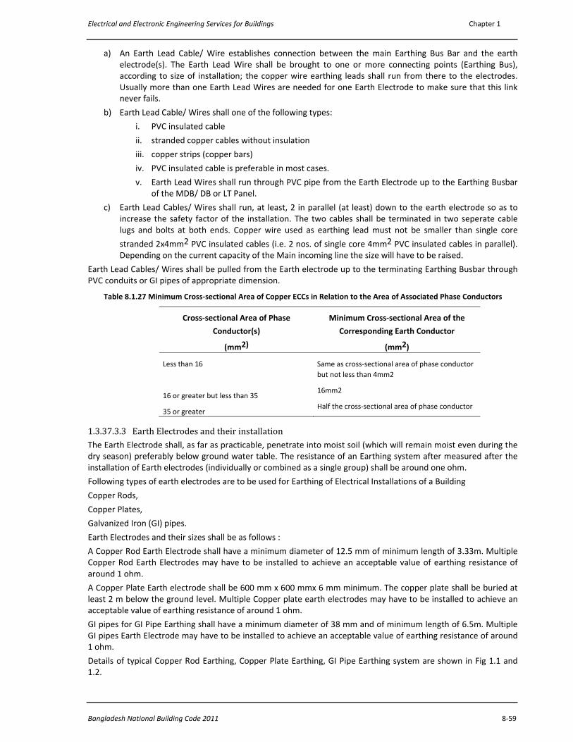
Electrical and Electronic Engineering Services for Buildings Chapter 1
Bangladesh National Building Code 2011 8‐59
a) An Earth Lead Cable/ Wire establishes connection between the main Earthing Bus Bar and the earth electrode(s). The Earth Lead Wire shall be brought to one or more connecting points (Earthing Bus), according to size of installation; the copper wire earthing leads shall run from there to the electrodes. Usually more than one Earth Lead Wires are needed for one Earth Electrode to make sure that this link never fails.
b) Earth Lead Cable/ Wires shall one of the following types:
i. PVC insulated cable
ii. stranded copper cables without insulation
iii. copper strips (copper bars)
iv. PVC insulated cable is preferable in most cases.
v. Earth Lead Wires shall run through PVC pipe from the Earth Electrode up to the Earthing Busbar of the MDB/ DB or LT Panel.
c) Earth Lead Cables/ Wires shall run, at least, 2 in parallel (at least) down to the earth electrode so as to increase the safety factor of the installation. The two cables shall be terminated in two seperate cable lugs and bolts at both ends. Copper wire used as earthing lead must not be smaller than single core
stranded 2x4mm2 PVC insulated cables (i.e. 2 nos. of single core 4mm2 PVC insulated cables in parallel). Depending on the current capacity of the Main incoming line the size will have to be raised.
Earth Lead Cables/ Wires shall be pulled from the Earth electrode up to the terminating Earthing Busbar through PVC conduits or GI pipes of appropriate dimension.
Table 8.1.27 Minimum Cross‐sectional Area of Copper ECCs in Relation to the Area of Associated Phase Conductors
Cross‐sectional Area of Phase
Conductor(s)
(mm2)
Minimum Cross‐sectional Area of the
Corresponding Earth Conductor
(mm2)
Less than 16
16 or greater but less than 35
35 or greater
Same as cross‐sectional area of phase conductor but not less than 4mm2
16mm2
Half the cross‐sectional area of phase conductor
1.3.37.3.3 Earth Electrodes and their installation The Earth Electrode shall, as far as practicable, penetrate into moist soil (which will remain moist even during the dry season) preferably below ground water table. The resistance of an Earthing system after measured after the installation of Earth electrodes (individually or combined as a single group) shall be around one ohm. Following types of earth electrodes are to be used for Earthing of Electrical Installations of a Building
Copper Rods,
Copper Plates,
Galvanized Iron (GI) pipes.
Earth Electrodes and their sizes shall be as follows :
A Copper Rod Earth Electrode shall have a minimum diameter of 12.5 mm of minimum length of 3.33m. Multiple Copper Rod Earth Electrodes may have to be installed to achieve an acceptable value of earthing resistance of around 1 ohm.
A Copper Plate Earth electrode shall be 600 mm x 600 mmx 6 mm minimum. The copper plate shall be buried at least 2 m below the ground level. Multiple Copper plate earth electrodes may have to be installed to achieve an acceptable value of earthing resistance of around 1 ohm.
GI pipes for GI Pipe Earthing shall have a minimum diameter of 38 mm and of minimum length of 6.5m. Multiple GI pipes Earth Electrode may have to be installed to achieve an acceptable value of earthing resistance of around 1 ohm.
Details of typical Copper Rod Earthing, Copper Plate Earthing, GI Pipe Earthing system are shown in Fig 1.1 and 1.2.
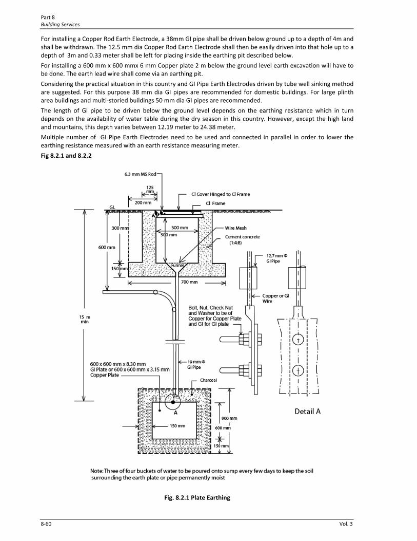
Part 8 Building Services
8‐60 Vol. 3
For installing a Copper Rod Earth Electrode, a 38mm GI pipe shall be driven below ground up to a depth of 4m and shall be withdrawn. The 12.5 mm dia Copper Rod Earth Electrode shall then be easily driven into that hole up to a depth of 3m and 0.33 meter shall be left for placing inside the earthing pit described below.
For installing a 600 mm x 600 mmx 6 mm Copper plate 2 m below the ground level earth excavation will have to be done. The earth lead wire shall come via an earthing pit.
Considering the practical situation in this country and GI Pipe Earth Electrodes driven by tube well sinking method are suggested. For this purpose 38 mm dia GI pipes are recommended for domestic buildings. For large plinth area buildings and multi‐storied buildings 50 mm dia GI pipes are recommended.
The length of GI pipe to be driven below the ground level depends on the earthing resistance which in turn depends on the availability of water table during the dry season in this country. However, except the high land and mountains, this depth varies between 12.19 meter to 24.38 meter.
Multiple number of GI Pipe Earth Electrodes need to be used and connected in parallel in order to lower the earthing resistance measured with an earth resistance measuring meter.
Fig 8.2.1 and 8.2.2
Fig. 8.2.1 Plate Earthing
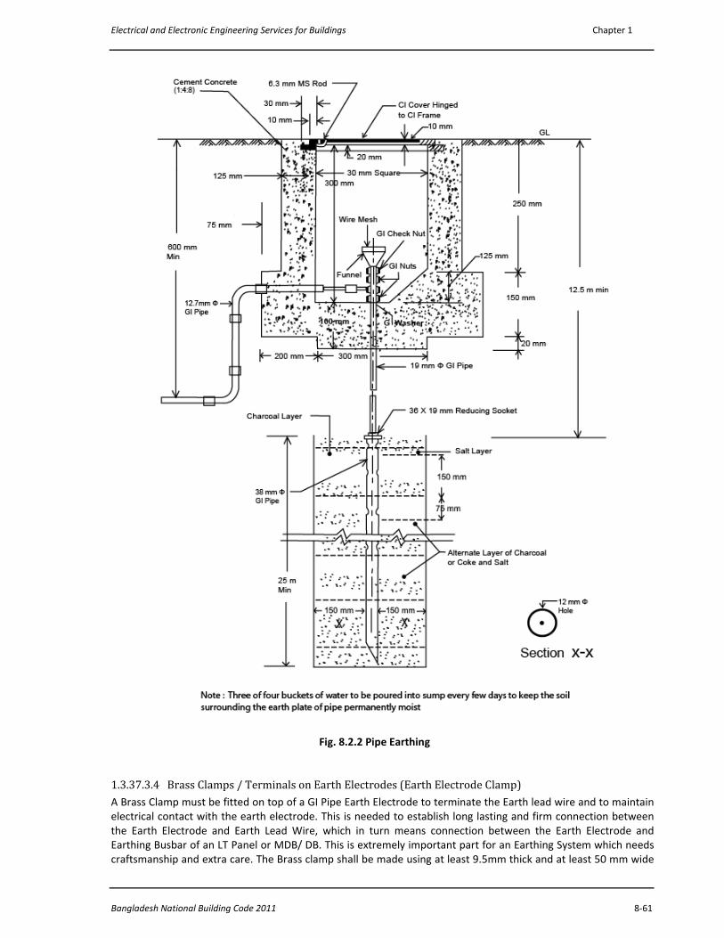
Electrical and Electronic Engineering Services for Buildings Chapter 1
Bangladesh National Building Code 2011 8‐61
Fig. 8.2.2 Pipe Earthing
1.3.37.3.4 Brass Clamps / Terminals on Earth Electrodes (Earth Electrode Clamp) A Brass Clamp must be fitted on top of a GI Pipe Earth Electrode to terminate the Earth lead wire and to maintain electrical contact with the earth electrode. This is needed to establish long lasting and firm connection between the Earth Electrode and Earth Lead Wire, which in turn means connection between the Earth Electrode and Earthing Busbar of an LT Panel or MDB/ DB. This is extremely important part for an Earthing System which needs craftsmanship and extra care. The Brass clamp shall be made using at least 9.5mm thick and at least 50 mm wide

Part 8 Building Services
8‐62 Vol. 3
Brass plate bent and shaped properly to fit tightly around the GI pipe earth electrode and shall have sufficient length (at least 35mm) on both sides for fixing bolts and cable lugs. This clamp shall have two hexagonal head 9.5 mm bolts on one side and two hexagonal head 9.5mm bolts on the other side. Sufficient space should be available for fixing the cable lugs of the Earth Lead Wires. After fitting the lugs of the Earth Lead Cables the Brass clamp and the GI pipe head should be coated with two coats of synthetic enamel paint on top of one undercoat paint layer.
1.3.37.3.5 Earthing Busbars A Copper Earthing Busbar must be provided inside the LT Panel or MDB/ DB of a building. The Earth Lead Wire coming from the Earth Electrode (s) shall be terminated on this bus bar using cable lugs (cable lugs must be fitted using crimp tools or hydraulic press) and brass bolts and nuts.
Copper Earthing Busbar must also be provided inside the DBs, FDBs, SDBs andBDBs. Hexagonal Head brass screw, nuts and washers are needed for fixing the ECC and Earth Lead cables with this busbar
1.3.37.3.6 Earthing Pit An Earthing Pit must be constructed around the top of the Earth Electrode, below the ground level using 254mm brick walls on a CC floor with a 152mm thick RCC slab cover on top having lifting hooks. The top of the Earth electrode (in case of pipe earthing) shall remain 380mm above the top of the bottom CC floor of the pit. The minimum inside dimension of the Earthing Pit shall be 610mm X 610mm X 610mm. The outside as well as the inside of the walls of the pit and the floor of the pit shall be cement mortar plastered. The inside shall be net cement finished. The top of the RCC slab pit cover shall remain 38mm above the ground level. The pit shall be made in such a way that water cannot get in to the pit. One Earthing Pit is needed for one Earth Electrode.
1.3.38 Lightning Protection of Buildings
1.3.38.1 General
Whether a building needs protection against lightning depends on the probability of a stroke and acceptable risk levels. Assessment of the risk and of the magnitude of the consequences need to be made. As an aid to making a judgement, a set of indices is given in Table 8.1.28 below for the various factors involved.
1.3.38.1.1 Importance of Structure The lightning hazard to human beings within a structure or a building is a very important factor in deciding how far to go in providing lightning protection. Schools, hospitals, auditoriums, railway stations, etc., are places where a large number of people congregate and, therefore, would in general be structures of greater importance than small buildings and houses.
1.3.38.1.2 Type of Construction The type of construction of the structure has a large influence upon the extent of protection to be provided. A steel framed building to some extent is self‐protecting and may not generally require additional protection, while brick buildings or buildings with thatched roof require greater degree of protection.
1.3.38.1.3 Fire and Loss due to Lightning In addition to direct loss due to destruction of buildings by lightning, fire resulting from lightning, killing of livestock, etc. there may be indirect losses which sometimes accompany the destruction of buildings and their contents. An interruption to business or to farming operations, specially, at certain times of the year, may involve losses quite distinct from, and in addition to, the losses arising from the direct destruction of property. There are also cases where whole community depends for safety and comfort in some respect on the integrity of a single structure, as for instance on the brick chimney of a water pumping plant. A lightning strike to it may have a serious consequence due to disruption of sanitary facilities, drinking water, water for irrigation, fire protection, etc. The contents of buildings should also be considered as to whether they are replaceable, explosive, combustible, flammable vapour or explosive dust. These may present a hazard in a building that is otherwise immune to lightning. Protection measures are extremely necessary for houses where items like hay or cotton are stored.
1.3.38.1.4 Degree of Isolation The relative exposure of a particular building will be an element in determining whether the expense of lightning protection is warranted. In closely built‐up towns and cities, the hazard is not as great as in the open country.
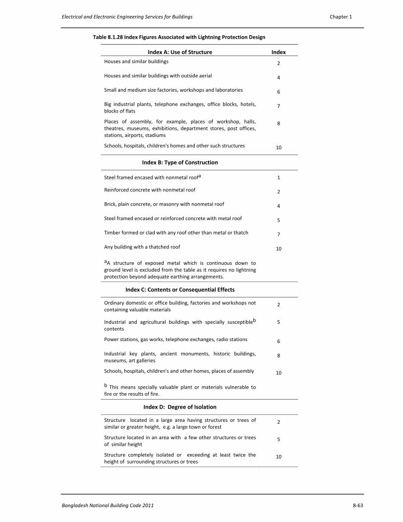
Electrical and Electronic Engineering Services for Buildings Chapter 1
Bangladesh National Building Code 2011 8‐63
Table 8.1.28 Index Figures Associated with Lightning Protection Design
Index A: Use of Structure Index
Houses and similar buildings 2
Houses and similar buildings with outside aerial 4
Small and medium size factories, workshops and laboratories 6
Big industrial plants, telephone exchanges, office blocks, hotels, blocks of flats
7
Places of assembly, for example, places of workshop, halls, theatres, museums, exhibitions, department stores, post offices, stations, airports, stadiums
8
Schools, hospitals, children's homes and other such structures 10
Index B: Type of Construction
Steel framed encased with nonmetal roofa 1
Reinforced concrete with nonmetal roof 2
Brick, plain concrete, or masonry with nonmetal roof 4
Steel framed encased or reinforced concrete with metal roof 5
Timber formed or clad with any roof other than metal or thatch 7
Any building with a thatched roof 10
aA structure of exposed metal which is continuous down to ground level is excluded from the table as it requires no lightning protection beyond adequate earthing arrangements.
Index C: Contents or Consequential Effects
Ordinary domestic or office building, factories and workshops not containing valuable materials
2
Industrial and agricultural buildings with specially susceptibleb
contents 5
Power stations, gas works, telephone exchanges, radio stations 6
Industrial key plants, ancient monuments, historic buildings, museums, art galleries
8
Schools, hospitals, children's and other homes, places of assembly 10
b This means specially valuable plant or materials vulnerable to fire or the results of fire.
Index D: Degree of Isolation
Structure located in a large area having structures or trees of similar or greater height, e.g. a large town or forest
2
Structure located in an area with a few other structures or trees of similar height
5
Structure completely isolated or exceeding at least twice the height of surrounding structures or trees
10
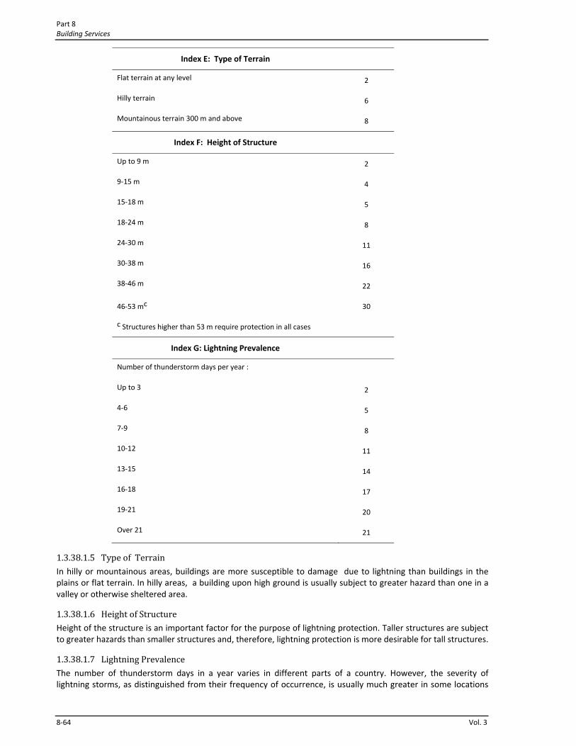
Part 8 Building Services
8‐64 Vol. 3
Index E: Type of Terrain
Flat terrain at any level 2
Hilly terrain 6
Mountainous terrain 300 m and above 8
Index F: Height of Structure
Up to 9 m 2
9‐15 m 4
15‐18 m 5
18‐24 m 8
24‐30 m 11
30‐38 m 16
38‐46 m 22
46‐53 mc 30
c Structures higher than 53 m require protection in all cases
Index G: Lightning Prevalence
Number of thunderstorm days per year :
Up to 3 2
4‐6 5
7‐9 8
10‐12 11
13‐15 14
16‐18 17
19‐21 20
Over 21 21
1.3.38.1.5 Type of Terrain In hilly or mountainous areas, buildings are more susceptible to damage due to lightning than buildings in the plains or flat terrain. In hilly areas, a building upon high ground is usually subject to greater hazard than one in a valley or otherwise sheltered area.
1.3.38.1.6 Height of Structure Height of the structure is an important factor for the purpose of lightning protection. Taller structures are subject to greater hazards than smaller structures and, therefore, lightning protection is more desirable for tall structures.
1.3.38.1.7 Lightning Prevalence The number of thunderstorm days in a year varies in different parts of a country. However, the severity of lightning storms, as distinguished from their frequency of occurrence, is usually much greater in some locations
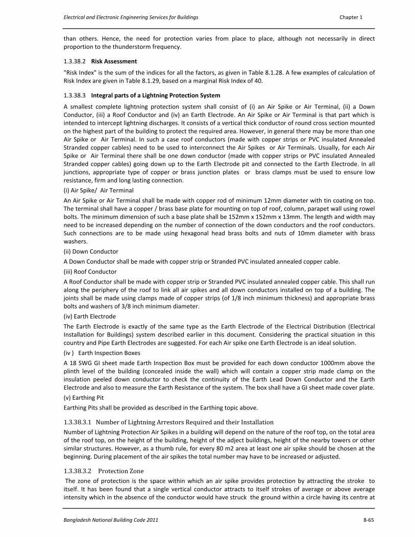
Electrical and Electronic Engineering Services for Buildings Chapter 1
Bangladesh National Building Code 2011 8‐65
than others. Hence, the need for protection varies from place to place, although not necessarily in direct proportion to the thunderstorm frequency.
1.3.38.2 Risk Assessment
"Risk Index" is the sum of the indices for all the factors, as given in Table 8.1.28. A few examples of calculation of Risk Index are given in Table 8.1.29, based on a marginal Risk Index of 40.
1.3.38.3 Integral parts of a Lightning Protection System
A smallest complete lightning protection system shall consist of (i) an Air Spike or Air Terminal, (ii) a Down Conductor, (iii) a Roof Conductor and (iv) an Earth Electrode. An Air Spike or Air Terminal is that part which is intended to intercept lightning discharges. It consists of a vertical thick conductor of round cross section mounted on the highest part of the building to protect the required area. However, in general there may be more than one Air Spike or Air Terminal. In such a case roof conductors (made with copper strips or PVC insulated Annealed Stranded copper cables) need to be used to interconnect the Air Spikes or Air Terminals. Usually, for each Air Spike or Air Terminal there shall be one down conductor (made with copper strips or PVC insulated Annealed Stranded copper cables) going down up to the Earth Electrode pit and connected to the Earth Electrode. In all junctions, appropriate type of copper or brass junction plates or brass clamps must be used to ensure low resistance, firm and long lasting connection.
(i) Air Spike/ Air Terminal An Air Spike or Air Terminal shall be made with copper rod of minimum 12mm diameter with tin coating on top. The terminal shall have a copper / brass base plate for mounting on top of roof, column, parapet wall using rowel bolts. The minimum dimension of such a base plate shall be 152mm x 152mm x 13mm. The length and width may need to be increased depending on the number of connection of the down conductors and the roof conductors. Such connections are to be made using hexagonal head brass bolts and nuts of 10mm diameter with brass washers.
(ii) Down Conductor
A Down Conductor shall be made with copper strip or Stranded PVC insulated annealed copper cable.
(iii) Roof Conductor
A Roof Conductor shall be made with copper strip or Stranded PVC insulated annealed copper cable. This shall run along the periphery of the roof to link all air spikes and all down conductors installed on top of a building. The joints shall be made using clamps made of copper strips (of 1/8 inch minimum thickness) and appropriate brass bolts and washers of 3/8 inch minimum diameter.
(iv) Earth Electrode
The Earth Electrode is exactly of the same type as the Earth Electrode of the Electrical Distribution (Electrical Installation for Buildings) system described earlier in this document. Considering the practical situation in this country and Pipe Earth Electrodes are suggested. For each Air spike one Earth Electrode is an ideal solution.
(iv ) Earth Inspection Boxes
A 18 SWG GI sheet made Earth Inspection Box must be provided for each down conductor 1000mm above the plinth level of the building (concealed inside the wall) which will contain a copper strip made clamp on the insulation peeled down conductor to check the continuity of the Earth Lead Down Conductor and the Earth Electrode and also to measure the Earth Resistance of the system. The box shall have a GI sheet made cover plate.
(v) Earthing Pit
Earthing Pits shall be provided as described in the Earthing topic above.
1.3.38.3.1 Number of Lightning Arrestors Required and their Installation Number of Lightning Protection Air Spikes in a building will depend on the nature of the roof top, on the total area of the roof top, on the height of the building, height of the adject buildings, height of the nearby towers or other similar structures. However, as a thumb rule, for every 80 m2 area at least one air spike should be chosen at the beginning. During placement of the air spikes the total number may have to be increased or adjusted.
1.3.38.3.2 Protection Zone The zone of protection is the space within which an air spike provides protection by attracting the stroke to itself. It has been found that a single vertical conductor attracts to itself strokes of average or above average intensity which in the absence of the conductor would have struck the ground within a circle having its centre at
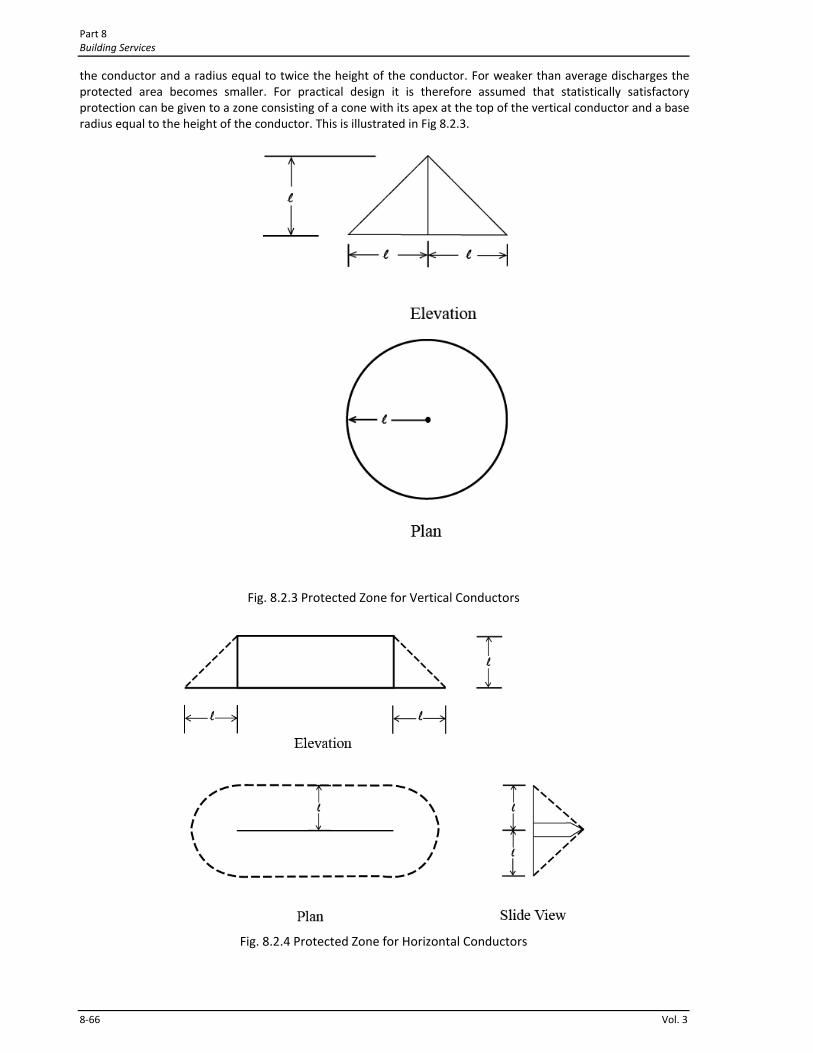
Part 8 Building Services
8‐66 Vol. 3
the conductor and a radius equal to twice the height of the conductor. For weaker than average discharges the protected area becomes smaller. For practical design it is therefore assumed that statistically satisfactory protection can be given to a zone consisting of a cone with its apex at the top of the vertical conductor and a base radius equal to the height of the conductor. This is illustrated in Fig 8.2.3.
Fig. 8.2.3 Protected Zone for Vertical Conductors
Fig. 8.2.4 Protected Zone for Horizontal Conductors
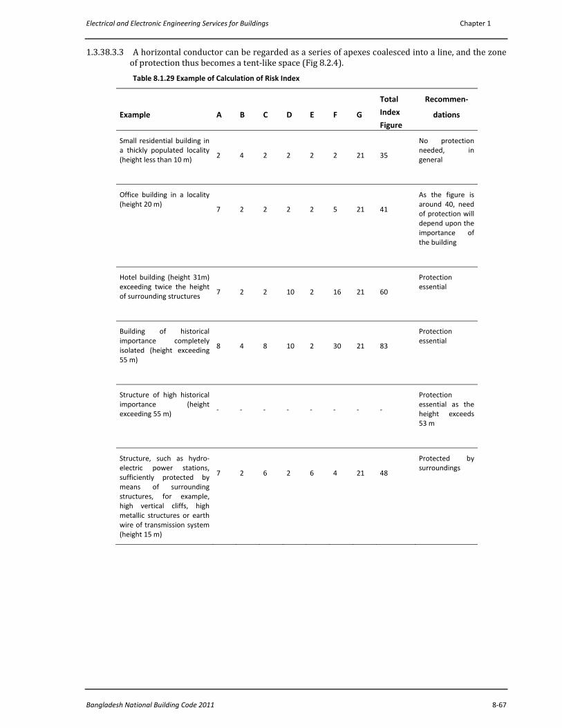
Electrical and Electronic Engineering Services for Buildings Chapter 1
Bangladesh National Building Code 2011 8‐67
1.3.38.3.3 A horizontal conductor can be regarded as a series of apexes coalesced into a line, and the zone of protection thus becomes a tent‐like space (Fig 8.2.4). Table 8.1.29 Example of Calculation of Risk Index
Example
A
B
C
D
E
F
G
Total
Index
Figure
Recommen‐
dations
Small residential building in a thickly populated locality (height less than 10 m)
2
4
2
2
2
2
21
35
No protection needed, in general
Office building in a locality (height 20 m)
7
2
2
2
2
5
21
41
As the figure is around 40, need of protection will depend upon the importance of the building
Hotel building (height 31m) exceeding twice the height of surrounding structures
7
2
2
10
2
16
21
60
Protection essential
Building of historical importance completely isolated (height exceeding 55 m)
8
4
8
10
2
30
21
83
Protection essential
Structure of high historical importance (height exceeding 55 m)
‐
‐
‐
‐
‐
‐
‐
‐
Protection essential as the height exceeds 53 m
Structure, such as hydro‐electric power stations, sufficiently protected by means of surrounding structures, for example, high vertical cliffs, high metallic structures or earth wire of transmission system (height 15 m)
7
2
6
2
6
4
21
48
Protected by surroundings
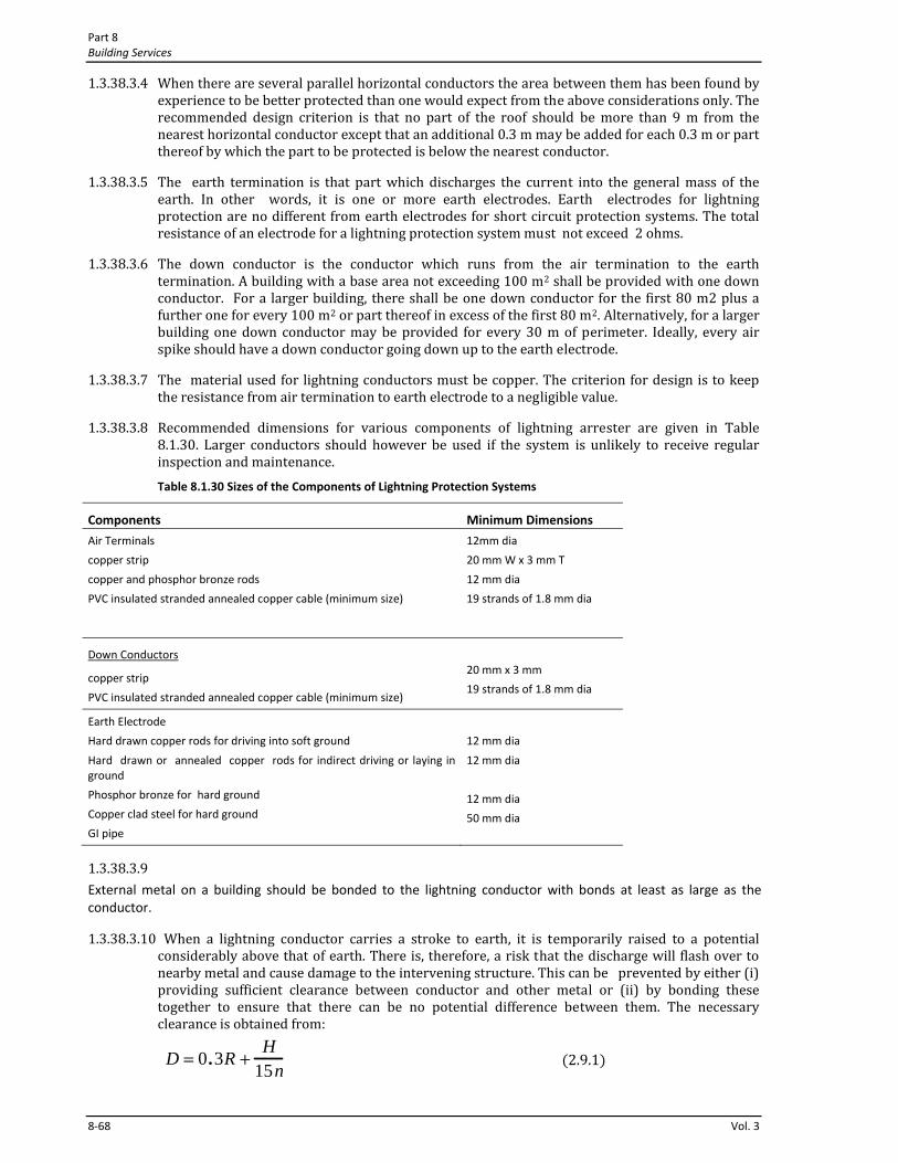
Part 8 Building Services
8‐68 Vol. 3
1.3.38.3.4 When there are several parallel horizontal conductors the area between them has been found by experience to be better protected than one would expect from the above considerations only. The recommended design criterion is that no part of the roof should be more than 9 m from the nearest horizontal conductor except that an additional 0.3 m may be added for each 0.3 m or part thereof by which the part to be protected is below the nearest conductor.
1.3.38.3.5 The earth termination is that part which discharges the current into the general mass of the earth. In other words, it is one or more earth electrodes. Earth electrodes for lightning protection are no different from earth electrodes for short circuit protection systems. The total resistance of an electrode for a lightning protection system must not exceed 2 ohms.
1.3.38.3.6 The down conductor is the conductor which runs from the air termination to the earth termination. A building with a base area not exceeding 100 m2 shall be provided with one down conductor. For a larger building, there shall be one down conductor for the first 80 m2 plus a further one for every 100 m2 or part thereof in excess of the first 80 m2. Alternatively, for a larger building one down conductor may be provided for every 30 m of perimeter. Ideally, every air spike should have a down conductor going down up to the earth electrode.
1.3.38.3.7 The material used for lightning conductors must be copper. The criterion for design is to keep the resistance from air termination to earth electrode to a negligible value.
1.3.38.3.8 Recommended dimensions for various components of lightning arrester are given in Table 8.1.30. Larger conductors should however be used if the system is unlikely to receive regular inspection and maintenance. Table 8.1.30 Sizes of the Components of Lightning Protection Systems
Components Minimum Dimensions
Air Terminals
copper strip
copper and phosphor bronze rods
PVC insulated stranded annealed copper cable (minimum size)
12mm dia
20 mm W x 3 mm T
12 mm dia
19 strands of 1.8 mm dia
Down Conductors
copper strip
PVC insulated stranded annealed copper cable (minimum size)
20 mm x 3 mm
19 strands of 1.8 mm dia
Earth Electrode
Hard drawn copper rods for driving into soft ground
Hard drawn or annealed copper rods for indirect driving or laying in ground
Phosphor bronze for hard ground
Copper clad steel for hard ground
GI pipe
12 mm dia
12 mm dia
12 mm dia
50 mm dia
1.3.38.3.9 External metal on a building should be bonded to the lightning conductor with bonds at least as large as the conductor.
1.3.38.3.10 When a lightning conductor carries a stroke to earth, it is temporarily raised to a potential considerably above that of earth. There is, therefore, a risk that the discharge will flash over to nearby metal and cause damage to the intervening structure. This can be prevented by either (i) providing sufficient clearance between conductor and other metal or (ii) by bonding these together to ensure that there can be no potential difference between them. The necessary clearance is obtained from:
D = 0.3R +
H15n
2.9.1
Electrical and Electronic Engineering Services for Buildings Chapter 1
Bangladesh National Building Code 2011 8‐69
where,
D = clearance in metres
R = resistance to earth in ohms
H = height of building in metres
n = number of down electrodes
Since it is often impracticable to provide the necessary clearance, the alternative technique of bonding is preferred.
1.3.38.3.11 Surge Arrester Selection A surge arrester is a protective device for limiting surge voltages by discharging, or bypassing, surge current through it. It also prevents continued flow of follow‐through current while remaining capable of repeating these functions. It is used to protect overhead lines, transformers and other electrical apparatus mostly in an outdoor substation from lightning voltages traveling through the overhead lines.
1.3.38.3.12 Horn‐gap lightning arresters Horn‐gap lightning arresters are commonly used for low and medium voltage overhead lines. The rating of the surge arrester shall be equal to or greater than the maximum continuous phase to ground power frequency voltage available at the point of application.
1.3.39 Telecommunications in Buildings
1.3.39.1 General
Placing concealed 2 pair indoor cables is needed to get (ii) telephone lines of the Wired Telphone Companies inside rooms of a building and (ii) to get the PABX lines of the building / offices in the building to the respective rooms under the PABXs. In addition to this, 10 pair/ 20 pair/ 50 pair telephone cables are required to be brought in to the PABX room(s) of the building. Conduits are to be installed for both of these two categories. For the entry of 10 pair/ 20 pair/ 50 pair cables, conduits through straight and easy path (in most cases, through one side of the vertical electrical duct) need to be brought in.
1.3.39.2 Concealed Telecommunication Cable Wiring
2 pair PVC insulated PVC sheathed annealed copper telecommunication cable shall be drawn through sufficient number of pre‐laid 19mm / 25mm / 38mm PVC conduits to establish Telecommunication Network inside a building. A clearance of at least 40% must be maintained inside the PVC conduits. Sufficient number of 18SWG GI sheet made pull boxes (with Perspex sheet / ebonite sheet cover plates) at all suitable places must be placed for the ease of pulling these cables.
2 pair PVC insulated PVC sheathed annealed copper telecommunication cable shall be used for wiring between a Telephone DP / Patch panel and a Telecommunication outlet. The extra pair shall remain for future maintenance. The minimum size of the copper wire of this cable shall be 0.5mm. The copper shall be preferably tinned.
1.3.39.3 Surface Telecommunication Cable Wiring
Surface wiring should not be a choice during designing a building wiring. However, if the building is already constructed or under compulsory conditions or for extension of an existing network one may go for surface wiring. The same 2 pair PVC insulated PVC sheathed annealed copper telecommunication cable shall be used for this purpose. Wiring shall be done either by using channels or by using PVC conduits following the power line surface wiring methods mentions earlier.
1.3.39.4 Telecommunications Outlets
Wall mounted Telecommunication outlets shall contain RJ11 or RJ45 connectors / jacks (shuttered). For simple telephone connection RJ11 shuttered jacks are sufficient. The outlet box shall have a back‐box which may be made of the same polymer material as the front panel or shall be made using18 SWG GI sheet or 18 SWG MS sheet but painted with two coats of synthetic enamel paint.
1.3.39.5 Telephone DP room, Patch Panel Room and Digital PABX room
Telephone DP room, Patch Panel Room and PABX room should be located near the vertical riser duct of the building so that the incoming 50 pair or 100 pair underground Telephone cable can be terminated in the DP/ MDF
Part 8 Building Services
8‐70 Vol. 3
or Patch Panel for distribution among the Flats of a Multistoried Residential Building or among the offices of a Multistoried Commercial / Office building.
If a Digital Telephone PABX is to be installed then this can be installed in the same room. A separate Earth Electrode with earth lead wire will be required for the PABX.
1.3.40 Television Antennas / Cable Television system In a multistoried residential / Office building, television antennas shall be placed at one suitably sited antenna location on roof top and connect these to individual flats/ residences/ Offices in the same building by coaxial cables through concealed conduits.
1.3.40.1 Cable work for Television Antennas / Cable Television system
Vertical duct and easy entry to each flats/ offices must be provided as sharp bending of these cables is difficult and harmful to the cables. These cables must not be placed in the same conduit with power cables. A distance of at least 350mm must be maintained if a portion runs in parallel with the power cable conduits.
RF and Video cables shall be PVC sheathed Co‐axial Cables shall be made with solid Copper centre conductor, foamed polythene insulated and further sealed Alluminium foil taped and Copper wire braided.
1.3.40.2 Television Antenna Outlets / Cable Television system outlets
Wall mounted Television coaxial cable outlets shall contain high quality coaxial connectors / jacks. The outlet box shall have a back‐box which may be made of the same polymer material as the front panel or 18 SWG GI sheet or 18 SWG MS sheet made but painted with two coats of synthetic enamel paint.
1.3.41 Data Communication Network for LAN and Internet Services inside a Building Data Communication Network for LAN and Internet Services inside a Building may be installed using Cat 6 unshielded twisted pair (UTP) cables in a concealed manner following the concealed wiring power cables installation procedure mentioned in the wiring methods section of this document. Each of the cables will be terminated at one end at the 8P8C ( RJ45) connector based data socket outlet board in the required rooms at the power socket level. On the other end, the cable will be terminated in the patch panel. From the patch panel up to the data socket outlet the cable shall be in one piece i.e., no joints will be allowed. As a result the concealed conduit work needs to be done carefully to have a straight line path and without any bend in the roof slab. Sufficient pull boxes will be required in the roof slab. Pull box will also be needed close to the vertical bend near the bend and ceiling at any downward drop of the conduit. The conduits must have 20 SWG GI pull wires during laying for pulling the cables later.
Because of the nature of these cables more clearances are needed inside the PVC conduits compared to the power cables.
If the conduits are running parallel to the power cables then there should be at least a distance of 410mm between these two.
Recently Cat. 7 cables are emerging as a better choice in place of Cat. 6 cables.
1.3.42 Fire Detection and Alarm System inside a Building The major parts of a Fire Detection and Alarm System inside a Building may be listed as
a) A number of different types of Fire Detectors/ detection devices wired in a number of radial circuits
b) Manual Callpoints
c) A central control panel for Fire Detection
d) A number of alarm sounders / alarm devices wired in a number of radial circuits
e) Cables for wiring the Fire Detectors/ detection devices
f) Cables for wiring the alarm sounders / alarm devices
Control Panel
The control panel will indicate in which detection circuit (zone) an alarm or fault condition has been generated and will operate common or zonal sounders and auxiliary commands (for example door release or Fire Brigade signaling).
Detectors
Electrical and Electronic Engineering Services for Buildings Chapter 1
Bangladesh National Building Code 2011 8‐71
A number of types of Detectors (smoke detectors, heat detectors, ionisation smoke detectors, Optical beam smoke detectors, Opto‐heat detectors) For the installation
Alarm Devices
Alarm devices fall into two types, audible and visual. The audible types are most common, with a variety of types being available from bells to all kinds of different electronic sounders including those containing pre‐recorded spoken messages. The choice of device is dependent on local preference, legal requirement and the need to have a tone distinct from all other building audible alarms.
Speech alarms or links to PA systems overcome some of the complacent responses to warning tones and can be used to good effect when carrying out regular fire tests in buildings where there are many people unfamiliar with the regular routines ‐ such as hotels. Finally visual alarms are to be used where the hard of hearing may be occupying a building or where the ambient noise is such (above 90dBA) that audible warning may not be heard, where hearing protectors are in use or where the sounder levels would need to be so high that they might impair the hearing of the building occupant.
Audible and Visual Alarm Devices
The audible types are most common, with a variety of types being available from bells to all kinds of different electronic sounders including those containing pre‐recorded spoken messages. The choice of device is dependent on local preference, legal requirement and the need to have a tone distinct from all other building audible alarms.
Cables for fire detectors
BS5839‐1:2002 introduced more onerous requirements for the types of cables used in fire detection and alarm systems. Fireproof cables should now be used for all parts of the system and enhanced fire resistance cables should be used where there is a requirement to ensure cable integrity over a longer period of time. For example when connecting to alarm sounders or where the connection between sub‐panels provides any part of the alarm signal path.
Fire alarm cables should be segregated from the cables of other systems; they should be clearly marked, preferably coloured red and should be routed through parts of the building that provide minimum risk. This latter point is particularly relevant where the use of the building is being changed ‐ for example if a fuel store is being moved.
Specific Areas of Application for Fire Detection and Alarm Equipment
The BS5839 suite of standards relate to specific areas of application for fire detection and alarm equipment. Specifically part 1 relates to public premises and part 6 relates to residential premises. BS5839‐1 is a comprehensive code of practice for fire detection and alarm systems, the requirements relate to both life and property protection and the standard includes much advice and comment with is very useful in informing the building owner or system specifier of the background to the requirements.
Codes of Practice For Different Types Of Fire Protection Systems
The parts of BS7273 are codes of practice for different types of fire protection systems. Generally this is considered separately to fire alarm systems but there may be occasions where a trade off can be made between the two systems, or where the two systems interact and must be interfaced.
Standards Relates To The Design And Performance of Items of Equipment That Make up a Fire Detection And Alarm System
The EN54 suite of standards relates to the design and performance of items of equipment that make up a fire detection and alarm system. Each part relates to a different piece of equipment, for example part 3 relates to alarm devices, part 11 to call points, part 4 to power supplies etc.
Fire Detection Zones
Fire detection zones are essentially a convenient way of dividing up a building to assist in quickly locating the position of a fire. BS 5839‐1 has some specific recommendations with respect to detection zones.
Wiring of the fire Detection and alarm system will be done using the concealed wiring and the surface wiring methods described in the power line wiring section of this document.
1.3.43 CCTV System inside a Building Installation of Cable network for CCTV System inside a Building shall be done following the guidelines given for Cable work for Television Antennas / Cable Television system earlier in this document.
Part 8 Building Services
8‐72 Vol. 3
For wiring of the power lines required for the Installation of CCTV System inside a Building will be done using the concealed wiring and the surface wiring methods described in the power line wiring section of this document.
1.3.44 Design and Installation of Access Control System Wiring of the Installation of Access Control Systems will be done using the concealed wiring and the surface wiring methods described in the power line wiring section of this document.
1.3.45 Installation of Electronic Security Systems Wiring of the Installation of Electronic Security Systems will be done using the concealed wiring and the surface wiring methods described in the power line wiring section of this document.
1.3.46 Qualification of the Contractor of Electrical and Electronic Engineering Works in a Building
A Contractor who will be working with the Electrical and Electronic Engineering Works in a Building must have appropriate abc license from the Electrical Licensing Board of Government of Bangladesh.
The contractor must have sufficient number of well trained and experienced technicians to execute the job. For big volume of work, the contractor must have at least one Graduate Electrical Engineer assigned for the job.
1.3.47 Inspection and Testing
1.3.47.1 General
Every installation shall, on completion and before being energized, be inspected and tested. The methods of test shall be such that no danger to persons or property or damage to equipment occurs even if the circuit tested is defective.
1.3.47.2 Periodic inspection and testing
Periodic inspection and testing shall be carried out in order to maintain the installation in a sound condition after putting it into service. Where an addition is to be made to the fixed wiring of an existing installation, the latter shall be examined for compliance with the recommendations of the Code.
1.3.47.3 Checking the conformity with the Bangladesh Standard
The individual equipment and materials which form part of the installation shall generally conform to the relevant Bangladesh Standard (BDS) wherever applicable. If there is no relevant Bangladesh standard specification for any item, these shall be approved by the appropriate authority.
1.3.47.4 Inspection of the colour identification of cables of wiring
For single phase, Red for Live, Black for Neutral, Gree+Yellow bi‐colour for ECC. For three phase, Red for L1, Yellow for L2, Blue for L3, Black for Neutral and Gree+Yellow bi‐colour for ECC and Earth Lead Wire.
1.3.47.5 Inspection of Earthing Terminal, Earthing Bus
Inspection should be made to check whether Brass made Earthing Terminals have been provided inside the metal back boxes of the switchboards and socket boards (welded or screwed to the metal back box) and whether the ECCs of the sub circuit have been terminated in these terminals. Inspection should be made to check whether at least one copper Earthing Bus Bar has been provided in the BDBs, SDBs, FDBs, DBs, MDBs and the LT panel and whether ECCs have been appropriately terminated in these Busbars using hexagonal head brass bolt and nuts. Also it should be checked whether the Earth Lead Wires have been properlyterminated in the LT Panel / MDB / DB as appropriate.
1.3.47.6 Insulation Tests
Insulation test is one of the most important tests for Electrical Installations in a Building.
1.3.47.6.1 Insulation resistance test shall be made on all electrical equipment, using a self‐contained instrument such as the direct indicating ohm‐meter of the generator type. DC potential shall be used in these tests and shall be as follows or an appropriate Meggar:
Electrical and Electronic Engineering Services for Buildings Chapter 1
Bangladesh National Building Code 2011 8‐73
Circuits below 230 volts 500 volts Meggar
Circuits between 230 volts to 400 volts 1000 volts Meggar
1.3.47.6.2 The minimum acceptable insulation resistance value is 5 mega ohms for LT lines. Before making connections at the ends of each cable run, the insulation resistance measurement test of each cable shall be made. Each conductor of a multi‐core cable shall be tested individually to all other conductors of the group and also to earth. If insulation resistance test readings are found to be less than the specified minimum in any conductor, the entire cable shall be replaced.
1.3.47.6.3 All transformers, switchgears etc. shall be subject to an insulation resistance measurement test to ground after installation but before any wiring is connected. Insulation tests shall be made between open contacts of circuit breakers, switches etc. and between each phase and earth.
1.3.47.7 Earth Resistance Test and the Continuity Resistance Test
1.3.47.7.1 Earth resistance tests shall be made on the system, separating and reconnecting each earth connection using earth resistance meter.
1.3.47.7.2 The electrical resistance of the Earth Continuity Conductor of different segment shall be measured separately using sensitive digital Ohm meter or by means of resistance bridge instrument. The resistance of the Earth Lead Wire shall be measured from the Earthing Busbar of the LT Panel / MDB /DB and the Earth Electrode(s). The electrical resistance of any section shall not exceed 1 ohm.
1.3.47.7.3 Where more than one earthing sets are installed, the earth resistance between two sets shall be measured by means of sensitive digital Ohm meter or by means of resistance bridge instrument. The earth resistance between two sets shall not exceed 1 ohm.
1.3.47.7.4 Operation Tests Current load measurement shall be made on equipment and on all power and lighting feeders using Clamp on Ammeters.
The current reading shall be taken in each phase wire and in each neutral wire while the circuit or equipment is operating under actual load conditions.
Clamp on Ammeters are required to take current readings without interrupting a circuit.
All light fittings shall be tested electrically and mechanically to check whether they comply with the standard specifications.
Fluorescent light fittings shall be tested so that when functioning no flickering or choke singing is felt.
1.3.47.8 Inspection of the Installation
On completion of wiring a general inspection shall be carried out by competent personnel in order to verify that the provisions of this Code and that of the Electricity Act of Bangladesh have been complied with. A certificate may be issued on satisfactory completion of the work in a format as shown in Appendix C. Items to be inspected are detailed in the following sections.
1.3.47.8.1 Inspection of Substation Installations In substation installations, it shall be checked whether:
a) The installation has been carried out in accordance with the approved drawings;
b) Phase to phase and phase to earth clearances are provided as required;
c) All equipment are efficiently earthed and properly connected to the required number of earth electrodes;
d) The required ground clearance to live terminals is provided;
Part 8 Building Services
8‐74 Vol. 3
e) Suitable fencing is provided with gate with lockable arrangements;
f) The required number of caution boards, fire fighting equipment, operating rods, rubber mats, etc., are kept in the substation;
g) In case of indoor substation sufficient ventilation and draining arrangements are made;
h) All cable trenches have covers of noninflammable material;
i) Free accessibility is provided for all equipment for normal operation;
j) All name plates are fixed and the equipment are fully painted;
k) All construction materials and temporary connections are removed;
l) Oil level , bus bar tightness, transformer tap position, etc. are in order;
m) Earth pipe troughs and cover slabs are provided for earth electrodes/earth pits and the neutral and LA earth pits are marked for easy identification;
n) Earth electrodes are of GI pipes or CI pipes or copper plates. For earth connections, brass bolts and nuts with lead washers are provided in the pipes/plates;
o) Earth pipe troughs and oil sumps/pits are free from rubbish, dirt and stone jelly and the earth connections are visible and easily accessible;
p) HT and LT panels and switchgears are all vermin and damp‐proof and all unused openings or holes are blocked properly;
q) The earth bus bars have tight connections and corrosion free joint surfaces;
r) Control switch fuses are provided at an accessible height from ground;
s) Adequate headroom is available in the transformer room for easy topping‐up of oil, maintenance, etc.;
t) Safety devices, horizontal and vertical barriers, bus bar covers/shrouds, automatic safety shutters/door interlock, handle interlock etc. are safe and in reliable operation in all panels and cubicles;
u) Clearances in the front, rear and sides of the main HT and LT and subswitch boards are adequate;
v) The switches operate freely; the 3 blades make contact at the same time, the arcing horns contact in advance; and the handles are provided with locking arrangements,
w) Insulators are free from cracks, and are clean;
x) In transformers, there is no oil leak;
y) Connections to bushing in transformers are light and maintain good contact;
z) Bushings are free from cracks and are clean;
aa) Accessories of transformers like breathers, vent pipe, buchholz relay, etc. are in order;
bb) Connections to gas relay in transformers are in order;
cc) In transformers, oil and winding temperature are set for specific requirements to pump out;
dd) In case of cable cellars, adequate arrangements exist to pump off water that has entered due to seepage or other reasons; and
ee) All incoming and outgoing circuits of HT and LT panels are clearly and indelibly labeled for identifications.
1.3.47.8.2 Inspection of Low Tension (LT) Installation In Low Tension (LT) or Medium Voltage (MV) Installations, it shall be checked whether:
a) All blocking materials that are used for safe transportation in switchgears, contactors, relays, etc. are removed;
b) All connections to the earthing system have provisions for periodical inspection;
c) Sharp cable bends are avoided and cables are taken in a smooth manner in the trenches or alongside the walls and ceilings using suitable support clamps at regular intervals;
d) Suitable linked switch or circuit breaker or lockable push button is provided near the motors/apparatus for controlling supply to the motor/apparatus in an easily accessible location;
e) Two separate and distinct earth connections are provided for the motor apparatus;
f) Control switch fuse is provided at an accessible height from ground for controlling supply to overhead travelling crane, hoists, overhead bus bar trunking;
Electrical and Electronic Engineering Services for Buildings Chapter 1
Bangladesh National Building Code 2011 8‐75
g) The metal rails on which the crane travels are electrically continuous and earthed and bonding of rails and earthing at both ends are done;
h) Four‐core cables are used for overhead travelling crane and portable equipment, the fourth core being used for earthing, and separate supply for lighting circuit is taken;
i) If flexible metallic hose is used for wiring to motors and other equipment, the wiring is enclosed to the full lengths, and the hose secured properly by approved means;
j) The cables are not taken through areas where they are likely to be damaged or chemically affected;
k) The screens and armours of the cables are earthed properly;
l) The belts of belt driven equipment are properly guarded;
m) Adequate precautions are taken to ensure that no live parts are so exposed as to cause danger; n) Installed Ammeters and voltmeters work properly and are tested; and
o) The relays are inspected visually by moving covers for deposits of dusts or other foreign matter.
1.3.47.8.3 Inspection of Overhead Lines For overhead lines, every care must be taken so that:
a) All conductors and apparatus including live parts thereof are inaccessible;
b) The types and size of supports are suitable for the overhead lines/conductors used and are in accordance with approved drawing and standards;
c) Clearances from ground level to the lowest conductor of overhead lines, sag conditions, etc. are in accordance with the relevant standard;
d) Where overhead lines cross the roads suitable grounded guarding shall be provided at road crossings,
e) Where overhead lines cross cross each other or are in proximity with one another, suitable guarding shall be provided at crossings to protect against possibility of the lines coming in contact with one another;
f) Every guard wire shall be properly grounded / earthed;
g) The type, size and suitability of the guarding arrangement provided shall be adequate;
h) Stays cables must be provided suitably with the overhead line carrying poles as required and shall be efficiently earthed at the bottom and and shall be provided with suitable stay insulators of appropriate voltages;
i) Anti‐climbing devices and Danger Board/Caution Board Notices are provided on all HT supports;
j) Clearances along the route are checked and all obstructions such as trees/branches and shrubs are cleared on the route to the required distance on either side;
k) Clearance between the live conductor and the earthed metal parts are adequate; and
l) For the service connections tapped off from the overhead lines, cutouts of adequate capacity are provided.
1.3.47.8.4 Inspection of Lighting Circuits The lighting circuits shall be checked to see whether:
a) Wooden boxes and panels are avoided in factories for mounting the lighting boards, switch controls, etc.;
b) Neutral links are provided in double pole switch fuses which are used for lighting control, and no fuse is provided in the neutral;
c) The plug points in the lighting circuit are all 3‐pin type, the third pin being suitably earthed;
d) Tamper proof interlocked switch socket and plug are used for locations easily accessible;
e) Lighting wiring in factory area is enclosed in conduit and the conduit is properly earthed, or alternatively, armoured cable wiring is used;
f) A separate earth wire is run in the lighting installation to provide earthing for plug points, fixtures and equipment;
g) Proper connectors and junction boxes are used wherever joints are in conductors or cross over of conductors takes place;
h) Cartridge fuse units are fitted with cartridge fuses only;
Part 8 Building Services
8‐76 Vol. 3
i) Clear and permanent identification marks are painted in all distribution boards, switchboards, sub‐main boards and switches as necessary;
j) The polarity has been checked and all fuses and single pole switches are connected on the phase conductor only and wiring is correctly connected to socket outlets;
k) Spare knockouts provided in distribution boards and switch fuses are blocked;
l) The ends of conduits enclosing the wiring leads are provided with ebonite or other suitable bushes;
m) The fittings and fixtures used for outdoor use are all of weatherproof construction, and similarly, fixtures, fittings and switchgears used in the hazardous area are of flameproof application;
n) Proper terminal connectors are used for termination of wires (conductors and earth leads) and all strands are inserted in the terminals;
o) Flat ended screws are used for fixing conductor to the accessories;
p) Flat washers backed up by spring washers are used for making end connections.
1.3.47.8.5 Accessibility of Connections and Cable joints for Inspection Except for the following, every connection and joint shall be accessible for inspection, testing and maintenance:
a) a compound‐filled or encapsulated joint
b) a connection between a cold tail and a heating element (e.g. a ceiling and floor heating system, a pipe trace‐heating system)
c) a joint made by welding, soldering, brazing or compression tool
d) a joint formatting part of the equipment complying with the appropriate product standard.
Relevant Appendices:‐
Appendix 8.1.A Maximum Demand and Diversity
Appendix 8.1.B Useful Tables Relating to Conductor Sizes
Appendix 8.1.C Completion Certificate Form