
PART 179—SPECIFICATIONS FOR TANK CARS - GPO
58
257 Pipeline and Hazardous Materials Safety Admin., DOT Pt. 179 (1) A complete description of the materials tested including type, manufacturer, thick- ness, and other appropriate data. (2) Observations of the behavior of the test specimens during flame exposure such as delamination, resin ignition, smoke, etc., in- cluding the time of such occurrence. (3) The time at which flame penetration occurs, if applicable, for each of the three specimens tested. [72FR55099, Sept. 28, 2007] PART 179—SPECIFICATIONS FOR TANK CARS Subpart A—Introduction, Approvals and Reports Sec. 179.1 General. 179.2 Definitions and abbreviations. 179.3 Procedure for securing approval. 179.4 Changes in specifications for tank cars. 179.5 Certificate of construction. 179.6 Repairs and alterations. 179.7 Quality assurance program. 179.8 Limitation on actions by states, local governments, and Indian tribes. Subpart B—General Design Requirements 179.10 Tank mounting. 179.11 Welding certification. 179.12 Interior heater systems. 179.13 Tank car capacity and gross weight limitation. 179.14 Coupler vertical restraint system. 179.15 Pressure relief devices. 179.16 Tank-head puncture-resistance sys- tems. 179.18 Thermal protection systems. 179.20 Service equipment; protection sys- tems. 179.22 Marking. Subpart C—Specifications for Pressure Tank Car Tanks (Classes DOT-105, 109, 112, 114, and 120) 179.100 General specifications applicable to pressure tank car tanks. 179.100–1 Tanks built under these specifica- tions shall comply with the requirements of §§ 179.100, 179.101 and when applicable, §§ 179.102 and 179.103. 179.100–3 Type. 179.100–4 Insulation. 179.100–6 Thickness of plates. 179.100–7 Materials. 179.100–8 Tank heads. 179.100–9 Welding. 179.100–10 Postweld heat treatment. 179.100–12 Manway nozzle, cover and protec- tive housing. 179.100–13 Venting, loading and unloading valves, measuring and sampling devices. 179.100–14 Bottom outlets. 179.100–16 Attachments. 179.100–17 Closures for openings. 179.100–18 Tests of tanks. 179.100–19 Tests of safety relief valves. 179.100–20 Stamping. 179.101 Individual specification require- ments applicable to pressure tank car tanks. 179.101–1 Individual specification require- ments. 179.102 Special commodity requirements for pressure tank car tanks. 179.102–1 Carbon dioxide, refrigerated liquid. 179.102–2 Chlorine. 179.102–3 Materials poisonous by inhalation. 179.102–4 Vinyl fluoride, stabilized. 179.102–17 Hydrogen chloride, refrigerated liquid. 179.103 Special requirements for class 114A * * * tank car tanks. 179.103–1 Type. 179.103–2 Manway cover. 179.103–3 Venting, loading and unloading valves, measuring and sampling devices. 179.103–4 Safety relief devices and pressure regulators. 179.103–5 Bottom outlets. Subpart D—Specifications for Nonpressure Tank Car Tanks (Classes DOT-111AW and 115AW) 179.200 General specifications applicable to non-pressure tank car tanks (Class DOT 111). 179.200–1 Tank built under these specifica- tions must meet the requirements of §§ 179.200, and 179.201. 179.200–3 Type. 179.200–4 Insulation. 179.200–6 Thickness of plates. 179.200–7 Materials. 179.200–8 Tank heads. 179.200–9 Compartment tanks. 179.200–10 Welding. 179.200–11 Postweld heat treatment. 179.200–13 Manway ring or flange, pressure relief device flange, bottom outlet nozzle flange, bottom washout nozzle flange and other attachments and openings. 179.200–14 Expansion capacity. 179.200–15 Closures for manways. 179.200–16 Gauging devices, top loading and unloading devices, venting and air inlet devices. 179.200–17 Bottom outlets. 179.200–19 Reinforcements, when used, and appurtenances not otherwise specified. 179.200–21 Closures for openings. 179.200–22 Test of tanks. 179.200–23 Tests of pressure relief valves. 179.200–24 Stamping. VerDate Mar<15>2010 14:56 Jan 03, 2012 Jkt 223216 PO 00000 Frm 00269 Fmt 8010 Sfmt 8010 Y:\SGML\223216.XXX 223216 wreier-aviles on DSK3TPTVN1PROD with CFR
Transcript of PART 179—SPECIFICATIONS FOR TANK CARS - GPO

257
Pipeline and Hazardous Materials Safety Admin., DOT Pt. 179
(1) A complete description of the materials tested including type, manufacturer, thick-ness, and other appropriate data.
(2) Observations of the behavior of the test specimens during flame exposure such as delamination, resin ignition, smoke, etc., in-cluding the time of such occurrence.
(3) The time at which flame penetration occurs, if applicable, for each of the three specimens tested.
[72FR55099, Sept. 28, 2007]
PART 179—SPECIFICATIONS FOR TANK CARS
Subpart A—Introduction, Approvals and Reports
Sec. 179.1 General. 179.2 Definitions and abbreviations. 179.3 Procedure for securing approval. 179.4 Changes in specifications for tank
cars. 179.5 Certificate of construction. 179.6 Repairs and alterations. 179.7 Quality assurance program. 179.8 Limitation on actions by states, local
governments, and Indian tribes.
Subpart B—General Design Requirements
179.10 Tank mounting. 179.11 Welding certification. 179.12 Interior heater systems. 179.13 Tank car capacity and gross weight
limitation. 179.14 Coupler vertical restraint system. 179.15 Pressure relief devices. 179.16 Tank-head puncture-resistance sys-
tems. 179.18 Thermal protection systems. 179.20 Service equipment; protection sys-
tems. 179.22 Marking.
Subpart C—Specifications for Pressure Tank Car Tanks (Classes DOT-105, 109, 112, 114, and 120)
179.100 General specifications applicable to pressure tank car tanks.
179.100–1 Tanks built under these specifica-tions shall comply with the requirements of §§ 179.100, 179.101 and when applicable, §§ 179.102 and 179.103.
179.100–3 Type. 179.100–4 Insulation. 179.100–6 Thickness of plates. 179.100–7 Materials. 179.100–8 Tank heads. 179.100–9 Welding. 179.100–10 Postweld heat treatment. 179.100–12 Manway nozzle, cover and protec-
tive housing.
179.100–13 Venting, loading and unloading valves, measuring and sampling devices.
179.100–14 Bottom outlets. 179.100–16 Attachments. 179.100–17 Closures for openings. 179.100–18 Tests of tanks. 179.100–19 Tests of safety relief valves. 179.100–20 Stamping. 179.101 Individual specification require-
ments applicable to pressure tank car tanks.
179.101–1 Individual specification require-ments.
179.102 Special commodity requirements for pressure tank car tanks.
179.102–1 Carbon dioxide, refrigerated liquid. 179.102–2 Chlorine. 179.102–3 Materials poisonous by inhalation. 179.102–4 Vinyl fluoride, stabilized. 179.102–17 Hydrogen chloride, refrigerated
liquid. 179.103 Special requirements for class 114A
* * * tank car tanks. 179.103–1 Type. 179.103–2 Manway cover. 179.103–3 Venting, loading and unloading
valves, measuring and sampling devices. 179.103–4 Safety relief devices and pressure
regulators. 179.103–5 Bottom outlets.
Subpart D—Specifications for Nonpressure Tank Car Tanks (Classes DOT-111AW and 115AW)
179.200 General specifications applicable to non-pressure tank car tanks (Class DOT 111).
179.200–1 Tank built under these specifica-tions must meet the requirements of §§ 179.200, and 179.201.
179.200–3 Type. 179.200–4 Insulation. 179.200–6 Thickness of plates. 179.200–7 Materials. 179.200–8 Tank heads. 179.200–9 Compartment tanks. 179.200–10 Welding. 179.200–11 Postweld heat treatment. 179.200–13 Manway ring or flange, pressure
relief device flange, bottom outlet nozzle flange, bottom washout nozzle flange and other attachments and openings.
179.200–14 Expansion capacity. 179.200–15 Closures for manways. 179.200–16 Gauging devices, top loading and
unloading devices, venting and air inlet devices.
179.200–17 Bottom outlets. 179.200–19 Reinforcements, when used, and
appurtenances not otherwise specified. 179.200–21 Closures for openings. 179.200–22 Test of tanks. 179.200–23 Tests of pressure relief valves. 179.200–24 Stamping.
VerDate Mar<15>2010 14:56 Jan 03, 2012 Jkt 223216 PO 00000 Frm 00269 Fmt 8010 Sfmt 8010 Y:\SGML\223216.XXX 223216wre
ier-
avile
s on
DS
K3T
PT
VN
1PR
OD
with
CF
R

258
49 CFR Ch. I (10–1–11 Edition) Pt. 179
179.201 Individual specification require-ments applicable to non-pressure tank car tanks.
179.201–1 Individual specification require-ments.
179.201–2 [Reserved] 179.201–3 Lined tanks. 179.201–4 Material. 179.201–5 Postweld heat treatment and cor-
rosion resistance. 179.201–6 Manways and manway closures. 179.201–8 Sampling device and thermometer
well. 179.201–9 Gauging device. 179.201–10 Water capacity marking. 179.201–11 Insulation. 179.202—179.202–22 [Reserved] 179.220 General specifications applicable to
nonpressure tank car tanks consisting of an inner container supported within an outer shell (class DOT-115).
179.220–1 Tanks built under these specifica-tions must meet the requirements of §§ 179.220 and 179.221.
179.220–3 Type. 179.220–4 Insulation. 179.220–6 Thickness of plates. 179.220–7 Materials. 179.220–8 Tank heads. 179.220–9 Compartment tanks. 179.220–10 Welding. 179.220–11 Postweld heat treatment. 179.220–13 Inner container manway nozzle
and cover. 179.220–14 Openings in the tanks. 179.220–15 Support system for inner con-
tainer. 179.220–16 Expansion capacity. 179.220–17 Gauging devices, top loading and
unloading devices, venting and air inlet devices.
179.220–18 Bottom outlets. 179.220–20 Reinforcements, when used, and
appurtenances not otherwise specified. 179.220–22 Closure for openings. 179.220–23 Test of tanks. 179.220–24 Tests of pressure relief valves. 179.220–25 Stamping. 179.220–26 Stenciling. 179.221 Individual specification require-
ments applicable to tank car tanks con-sisting of an inner container supported within an outer shell.
179.221–1 Individual specification require-ments.
Subpart E—Specifications for Multi-Unit Tank Car Tanks (Classes DOT-106A and 110AW)
179.300 General specifications applicable to multi-unit tank car tanks designed to be removed from car structure for filling and emptying (Classes DOT-106A and 110AW).
179.300–1 Tanks built under these specifica-tions shall meet the requirements of §§ 179.300 and 179.301.
179.300–3 Type and general requirements. 179.300–4 Insulation. 179.300–6 Thickness of plates. 179.300–7 Materials. 179.300–8 Tank heads. 179.300–9 Welding. 179.300–10 Postweld heat treatment. 179.300–12 Protection of fittings. 179.300–13 Venting, loading and unloading
valves. 179.300–14 Attachments not otherwise speci-
fied. 179.300–15 Pressure relief devices. 179.300–16 Tests of tanks. 179.300–17 Tests of pressure relief devices. 179.300–18 Stamping. 179.300–19 Inspection. 179.300–20 Reports. 179.301 Individual specification require-
ments for multi-unit tank car tanks. 179.302 [Reserved]
Subpart F—Specification for Cryogenic Liq-uid Tank Car Tanks and Seamless Steel Tanks (Classes DOT-113 and 107A)
179.400 General specification applicable to cryogenic liquid tank car tanks.
179.400–1 General. 179.400–3 Type. 179.400–4 Insulation system and perform-
ance standard. 179.400–5 Materials. 179.400–6 Bursting and buckling pressure. 179.400–7 Tank heads. 179.400–8 Thickness of plates. 179.400–9 Stiffening rings. 179.400–10 Sump or siphon bowl. 179.400–11 Welding. 179.400–12 Postweld heat treatment. 179.400–13 Support system for inner tank. 179.400–14 Cleaning of inner tank. 179.400–15 Radioscopy. 179.400–16 Access to inner tank. 179.400–17 Inner tank piping. 179.400–18 Test of inner tank. 179.400–19 Valves and gages. 179.400–20 Pressure relief devices. 179.400–21 Test of pressure relief valves. 179.400–22 Protective housings. 179.400–23 Operating instructions. 179.400–24 Stamping. 179.400–25 Stenciling. 179.401 Individual specification require-
ments applicable to inner tanks for cryo-genic liquid tank car tanks.
179.401–1 Individual specification require-ments.
179.500 Specification DOT-107A * * * *, seamless steel tank car tanks.
179.500–1 Tanks built under these specifica-tions shall meet the requirements of § 179.500.
179.500–3 Type and general requirements.
VerDate Mar<15>2010 14:56 Jan 03, 2012 Jkt 223216 PO 00000 Frm 00270 Fmt 8010 Sfmt 8010 Y:\SGML\223216.XXX 223216wre
ier-
avile
s on
DS
K3T
PT
VN
1PR
OD
with
CF
R

259
Pipeline and Hazardous Materials Safety Admin., DOT § 179.3
179.500–4 Thickness of wall. 179.500–5 Material. 179.500–6 Heat treatment. 179.500–7 Physical tests. 179.500–8 Openings in tanks. 179.500–10 Protective housing. 179.500–11 Loading and unloading valves. 179.500–12 Pressure relief devices. 179.500–13 Fixtures. 179.500–14 Test of tanks. 179.500–15 Handling of tanks failing in tests. 179.500–16 Tests of pressure relief devices. 179.500–17 Marking. 179.500–18 Inspection and reports.
APPENDIX A TO PART 179—PROCEDURES FOR TANK-HEAD PUNCTURE-RESISTANCE TEST
APPENDIX B TO PART 179—PROCEDURES FOR SIMULATED POOL AND TORCH-FIRE TEST-ING
AUTHORITY: 49 U.S.C. 5101–5128; 49 CFR part 1.53.
SOURCE: 29 FR 18995, Dec. 29, 1964, unless otherwise noted. Redesignated at 32 FR 5606, Apr. 5, 1967.
Subpart A—Introduction, Approvals and Reports
§ 179.1 General. (a) This part prescribes the specifica-
tions for tanks that are to be mounted on or form part of a tank car and which are to be marked with a DOT specifica-tion.
(b) Except as provided in paragraph (c) of this section, tanks to which this part is applicable, must be built to the specifications prescribed in this part.
(c) Tanks built to specifications pre-dating those in this part may continue in use as provided in § 180.507 of this subchapter.
(d) Any person who performs a func-tion prescribed in this part, shall per-form that function in accordance with this part.
(e) When this part requires a tank to be marked with a DOT specification (for example, DOT-105A100W), compli-ance with that requirement is the re-sponsibility of the tank builder. Mark-ing the tank with the DOT specifica-tion shall be understood to certify compliance by the builder that the functions performed by the builder, as prescribed in this part, have been per-formed in compliance with this part.
(f) The tank builder should inform each person to whom that tank is transferred of any specification re-
quirements which have not been met at time of transfer.
[Amdt. 179–17, 41 FR 38183, Sept. 9, 1976, as amended by Amdt. 179–50, 60 FR 49076, Sept. 21, 1995; 68 FR 48571, Aug. 14, 2003]
§ 179.2 Definitions and abbreviations.
(a) The following apply in part 179: (1) AAR means Association of Amer-
ican Railroads. (2) Approved means approval by the
AAR Tank Car Committee. (3) ASTM means American Society
for Testing and Materials. (4) [Reserved] (5) Definitions in part 173 of this
chapter also apply. (6) F means degrees Fahrenheit. (7) NGT means National Gas Taper
Threads. (8) NPT means an American Standard
Taper Pipe Thread conforming to the requirements of NBS Handbook H–28 (IBR, see § 171.7 of this subchapter).
(9) [Reserved] (10) Tank car facility means an entity
that manufactures, repairs, inspects, tests, qualifies, or maintains a tank car to ensure that the tank car con-forms to this part and subpart F of part 180 of this subchapter, that alters the certificate of construction of the tank car, that ensures the continuing quali-fication of a tank car by performing a function prescribed in parts 179 or 180 of this subchapter, or that makes any representation indicating compliance with one or more of the requirements of parts 179 or 180 of this subchapter.
(11) Tanks means tank car tanks. (b) [Reserved]
[29 FR 18995, Dec. 20, 1964. Redesignated at 32 FR 5606, Apr. 5, 1967, and amended by Amdt. 179–10, 36 FR 21344, Nov. 6, 1971; Amdt. 179–50, 60 FR 49076, Sept. 21, 1995; Amdt. 179–50, 61 FR 33255, June 26, 1996; 63 FR 52850, Oct. 1, 1998; 66 FR 45186, 45390, Aug. 28, 2001; 68 fR 75759, Dec. 31, 2003]
§ 179.3 Procedure for securing ap-proval.
(a) Application for approval of de-signs, materials and construction, con-version or alteration of tank car tanks under these specifications, complete with detailed prints, must be sub-mitted in prescribed form to the Exec-utive Director—Tank Car Safety, AAR,
VerDate Mar<15>2010 14:56 Jan 03, 2012 Jkt 223216 PO 00000 Frm 00271 Fmt 8010 Sfmt 8010 Y:\SGML\223216.XXX 223216wre
ier-
avile
s on
DS
K3T
PT
VN
1PR
OD
with
CF
R

260
49 CFR Ch. I (10–1–11 Edition) § 179.4
for consideration by its Tank Car Com-mittee and other appropriate commit-tees. Approval or rejections of applica-tions based on appropriate committee action will be issued by the executive director.
(b) When, in the opinion of the Com-mittee, such tanks or equipment are in compliance with the requirements of this subchapter, the application will be approved.
(c) When such tanks or equipment are not in compliance with the require-ments of this subchapter, the Com-mittee may recommend service trials to determine the merits of a change in specifications. Such service trials may be conducted only if the builder or shipper applies for and obtains a spe-cial permit.
[29 FR 18995, Dec. 29, 1964. Redesignated at 32 FR 5606, Apr. 5, 1967 and amended by Amdt. 179–41, 52 FR 36672, Sept. 30, 1987; 63 FR 52850, Oct. 1, 1998; 68 FR 48571, Aug. 14, 2003; 70 FR 73166, Dec. 9, 2005]
§ 179.4 Changes in specifications for tank cars.
(a) Proposed changes in or additions to specifications for tanks must be sub-mitted to the Executive Director— Tank Car Safety, AAR, for consider-ation by its Tank Car Committee. An application for construction of tanks to any new specification may be sub-mitted with proposed specification. Construction should not be started until the specification has been ap-proved or a special permit has been issued. When proposing a new specifica-tion, the applicant shall furnish infor-mation to justify a new specification. This data should include the properties of the lading and the method of loading and unloading.
(b) The Tank Car Committee will re-view the proposed specifications at its earliest convenience and report its rec-ommendations through the Executive Director—Tank Car Safety to the De-partment. The recommendation will be considered by the Department in deter-mining appropriate action.
[29 FR 18995, Dec. 29, 1964. Redesignated at 32 FR 5606, Apr. 5, 1967 and amended by Amdt. 179–41, 52 FR 36672, Sept. 30, 1987; 63 FR 52850, Oct. 1, 1998; 70 FR 73166, Dec. 9, 2005]
§ 179.5 Certificate of construction.
(a) Before a tank car is placed in service, the party assembling the com-pleted car shall furnish a Certificate of Construction, Form AAR 4–2 to the owner and the Executive Director— Tank Car Safety, AAR, certifying that the tank, equipment, and car fully con-forms to all requirements of the speci-fication.
(b) When cars or tanks are covered in one application and are identical in all details are built in series, one certifi-cate will suffice for each series when submitted to the Executive Director— Tank Car Safety, AAR.
(c) If the owner elects to furnish serv-ice equipment, the owner shall furnish the Executive Director—Tank Car Safety, AAR, a report in prescribed form, certifying that the service equip-ment complies with all the require-ments of the specifications.
(d) When cars or tanks which are cov-ered on one application and are iden-tical in all details are built in series, one certificate shall suffice for each se-ries when submitted to the Executive Director—Tank Car Safety, AAR. One copy of the Certificate of Construction must be furnished to the Executive Di-rector—Tank Car Safety, AAR for each car number of consecutively numbered group or groups covered by the original application.
[Amdt. 179–10, 36 FR 21344, Nov. 6, 1971, as amended at 63 FR 52850, Oct. 1, 1998; 68 FR 48571, Aug. 14, 2003]
§ 179.6 Repairs and alterations.
For procedure to be followed in mak-ing repairs or alterations, see appendix R of the AAR Specifications for Tank Cars (IBR, see § 171.7 of this sub-chapter).
[68 FR 75759, Dec. 31, 2003]
§ 179.7 Quality assurance program.
(a) At a minimum, each tank car fa-cility shall have a quality assurance program, approved by AAR, that—
(1) Ensures the finished product con-forms to the requirements of the appli-cable specification and regulations of this subchapter;
VerDate Mar<15>2010 14:56 Jan 03, 2012 Jkt 223216 PO 00000 Frm 00272 Fmt 8010 Sfmt 8010 Y:\SGML\223216.XXX 223216wre
ier-
avile
s on
DS
K3T
PT
VN
1PR
OD
with
CF
R

261
Pipeline and Hazardous Materials Safety Admin., DOT § 179.8
(2) Has the means to detect any non-conformity in the manufacturing, re-pair, inspection, testing, and qualifica-tion or maintenance program of the tank car; and
(3) Prevents non-conformities from recurring.
(b) At a minimum, the quality assur-ance program must have the following elements
(1) Statement of authority and re-sponsibility for those persons in charge of the quality assurance program.
(2) An organizational chart showing the interrelationship between man-agers, engineers, purchasing, construc-tion, inspection, testing, and quality control personnel.
(3) Procedures to ensure that the lat-est applicable drawings, design calcula-tions, specifications, and instructions are used in manufacture, inspection, testing, and repair.
(4) Procedures to ensure that the fab-rication and construction materials re-ceived are properly identified and docu-mented.
(5) A description of the manufac-turing, repair, inspection, testing, and qualification or maintenance program, including the acceptance criteria, so that an inspector can identify the char-acteristics of the tank car and the ele-ments to inspect, examine, and test at each point.
(6) Monitoring and control of proc-esses and product characteristics dur-ing production.
(7) Procedures for correction of nonconformities.
(8) Provisions indicating that the re-quirements of the AAR Specifications for Tank Cars (IBR, see § 171.7 of this subchapter), apply.
(9) Qualification requirements of per-sonnel performing non-destructive in-spections and tests.
(10) Procedures for evaluating the in-spection and test technique employed, including the accessibility of the area and the sensitivity and reliability of the inspection and test technique and minimum detectable crack length.
(11) Procedures for the periodic cali-bration and measurement of inspection and test equipment.
(12) A system for the maintenance of records, inspections, tests, and the in-
terpretation of inspection and test re-sults.
(c) Each tank car facility shall en-sure that only personnel qualified for each non-destructive inspection and test perform that particular operation.
(d) Each tank car facility shall pro-vide written procedures to its employ-ees to ensure that the work on the tank car conforms to the specification, AAR approval, and owner’s acceptance criteria.
(e) Each tank car facility shall train its employees in accordance with sub-part H of part 172 of this subchapter on the program and procedures specified in paragraph (b) of this section to en-sure quality.
(f) No tank car facility may manufac-ture, repair, inspect, test, qualify or maintain tank cars subject to require-ments of this subchapter, unless it is operating in conformance with a qual-ity assurance program and written pro-cedures required by paragraphs (a) and (b) of this section.
[Amdt. 179–50, 60 FR 49076, Sept. 21, 1995, as amended by Amdt. 179–50, 61 FR 33255, June 26, 1996; 68 FR 48571, Aug. 14, 2003; 68 FR 75759, Dec. 31, 2003]
§ 179.8 Limitation on actions by states, local governments, and Indian tribes.
Sections 5125 and 20106 of Title 49, United States Code, limit the author-ity of states, political subdivisions of states, and Indian tribes to impose re-quirements on the transportation of hazardous materials in commerce. A state, local, or Indian tribe require-ment on the transportation of haz-ardous materials by rail may be pre-empted under either 49 U.S.C. 5125 or 20106, or both.
(a) Section 171.1(f) of this subchapter describes the circumstances under which 49 U.S.C. 5125 preempts a re-quirement of a state, political subdivi-sion of a state, or Indian tribe.
(b) Under the Federal Railroad Safe-ty Act (49 U.S.C. 20106), administered by the Federal Railroad Administra-tion (see 49 CFR parts 200–244), laws, regulations and orders related to rail-road safety, including security, shall be nationally uniform to the extent prac-ticable. A state may adopt, or continue in force, a law, regulation, or order
VerDate Mar<15>2010 14:56 Jan 03, 2012 Jkt 223216 PO 00000 Frm 00273 Fmt 8010 Sfmt 8010 Y:\SGML\223216.XXX 223216wre
ier-
avile
s on
DS
K3T
PT
VN
1PR
OD
with
CF
R

262
49 CFR Ch. I (10–1–11 Edition) § 179.10
covering the same subject matter as a DOT regulation or order applicable to railroad safety and security (including the requirements in this subpart) only when an additional or more stringent state law, regulation, or order is nec-essary to eliminate or reduce an essen-tially local safety or security hazard; is not incompatible with a law, regula-tion, or order of the United States Gov-ernment; and does not unreasonably burden interstate commerce.
[74 FR 1801, Jan. 13, 2009]
Subpart B—General Design Requirements
§ 179.10 Tank mounting. (a) The manner in which tanks are
attached to the car structure shall be approved. The use of rivets to secure anchors to tanks prohibited.
(b) [Reserved]
§ 179.11 Welding certification. (a) Welding procedures, welders and
fabricators shall be approved. (b) [Reserved]
§ 179.12 Interior heater systems. (a) Interior heater systems shall be of
approved design and materials. If a tank is divided into compartments, a separate system shall be provided for each compartment.
(b) Each interior heater system shall be hydrostatically tested at not less than 13.79 bar (200 psig) and shall hold the pressure for 10 minutes without leakage or evidence of distress.
[Amdt. 179–52, 61 FR 28678, June 5, 1996, as amended by 66 FR 45390, Aug. 28, 2001]
§ 179.13 Tank car capacity and gross weight limitation.
Except as provided in this section, tank cars, built after November 30, 1970, or any existing tank cars that are converted, may not exceed 34,500 gal-lons (130,597 L) capacity or 263,000 pounds (119,295 kg) gross weight on rail.
(a) For other than tank cars con-taining poisonous-by-inhalation mate-rial, a tank car may be loaded to a gross weight on rail of up to 286,000 pounds (129,727 kg) upon approval by the Associate Administrator for Safe-ty, Federal Railroad Administration
(FRA). Tank cars must conform to the conditions of the approval and must be operated only under controlled inter-change conditions agreed to by partici-pating railroads.
(b) Tank cars containing poisonous- by-inhalation material meeting the ap-plicable authorized tank car specifica-tions listed in § 173.244(a)(2) or (3), or § 173.314(c) or (d) may have a gross weight on rail of up to 286,000 pounds (129,727 kg). Tank cars exceeding 263,000 pounds and up to 286,000 pounds gross weight on rail must meet the require-ments of AAR Standard S–286, Free/Un-restricted Interchange for 286,000 lb Gross Rail Load Cars (IBR; see § 171.7 of this subchapter). Any increase in weight above 263,000 pounds may not be used to increase the quantity of the contents of the tank car.
[74 FR 1802, Jan. 13, 2009, as amended at 75 FR 27216, May 14, 2010]
§ 179.14 Coupler vertical restraint sys-tem.
(a) Performance standard. Each tank car shall be equipped with couplers ca-pable of sustaining, without disengage-ment or material failure, vertical loads of at least 200,000 pounds (90,718.5 kg) applied in upward and downward direc-tions in combination with buff loads of 2,000 pounds (907.2 kg), when coupled to cars which may or may not be equipped with couplers having this vertical re-straint capability.
(b) Test verification. Except as pro-vided in paragraph (d) of this section, compliance with the requirements of paragraph (a) of this section shall be achieved by verification testing of the coupler vertical restraint system in ac-cordance with paragraph (c) of this sec-tion.
(c) Coupler vertical restraint tests. A coupler vertical restraint system shall be tested under the following condi-tions:
(1) The test coupler shall be tested with a mating coupler (or simulated coupler) having only frictional vertical force resistance at the mating inter-face; or a mating coupler (or simulated coupler) having the capabilities de-scribed in paragraph (a) of this section;
(2) The testing apparatus shall simu-late the vertical coupler performance at the mating interface and may not
VerDate Mar<15>2010 14:56 Jan 03, 2012 Jkt 223216 PO 00000 Frm 00274 Fmt 8010 Sfmt 8010 Y:\SGML\223216.XXX 223216wre
ier-
avile
s on
DS
K3T
PT
VN
1PR
OD
with
CF
R

263
Pipeline and Hazardous Materials Safety Admin., DOT § 179.15
interfere with coupler failure or other-wise inhibit failure due to force appli-cations and reactions; and
(3) The test shall be conducted as fol-lows:
(i) A minimum of 200,000 pounds (90,718.5 kg) vertical downward load shall be applied continuously for at least 5 minutes to the test coupler head simultaneously with the application of a nominal 2,000 pounds (907.2 kg) buff load;
(ii) The procedures prescribed in paragraph (c)(3)(i) of this section, shall be repeated with a minimum vertical upward load of 200,000 pounds (90,718.5 kg); and
(iii) A minimum of three consecutive successful tests shall be performed for each load combination prescribed in paragraphs (c)(3) (i) and (ii) of this sec-tion. A test is successful when a vertical disengagement or material failure does not occur during the appli-cation of any of the loads prescribed in this paragraph.
(d) Authorized couplers. As an alter-native to the test verifications in para-graph (c) of this section, the following couplers are authorized:
(1) E double shelf couplers designated by the Association of American Rail-roads’ Catalog Nos., SE60CHT, SE60CC, SE60CHTE, SE60CE, SE60DC, SE60DE, SE67CC, SE67CE, SE67BHT, SE67BC, SE67BHTE, SE67BE, SE68BHT, SE68BC, SE68BHTE, SE68BE, SE69AHTE, and SE69AE.
(2) F double shelf couplers designated by the Association of American Rail-roads’ Catalog Nos., SF70CHT, SF70CC, SF70CHTE, SF70CE, SF73AC, SF73AE, SF73AHT, SF73AHTE, SF79CHT, SF79CC, SF79CHTE, and SF79CE.
[Amdt. 179–42, 54 FR 38797, Sept. 20, 1989]
§ 179.15 Pressure relief devices. Except for DOT Class 106, 107, 110, and
113 tank cars, tanks must have a pres-sure relief device, made of material compatible with the lading, that con-forms to the following requirements:
(a) Performance standard. Each tank must have a pressure relief device, made of materials compatible with the lading, having sufficient flow capacity to prevent pressure build-up in the tank to no more than the flow rating pressure of the pressure relief device in
fire conditions as defined in appendix A of the AAR Specifications for Tank Cars (IBR, see § 171.7 of this sub-chapter).
(b) Settings for reclosing pressure relief devices. (1) Except as provided in para-graph (b)(2) of this section, a reclosing pressure relief valve must have a min-imum start-to-discharge pressure equal to the sum of the static head and gas padding pressure and the lading vapor pressure at the following reference temperatures:
(i) 46 °C (115 °F) for noninsulated tanks;
(ii) 43 °C (110 °F) for tanks having a thermal protection system incor-porating a metal jacket that provides an overall thermal conductance at 15.5 °C (60 °F) of no more than 10.22 kilojoules per hour per square meter per degree Celsius (0.5 Btu per hour/per square foot/per degree F) temperature differential; and
(iii) 41 °C (105 °F) for insulated tanks. (2)(i) The start-to-discharge pressure
of a pressure relief device may not be lower than 5.17 Bar (75 psig) or exceed 33 percent of the minimum tank burst pressure.
(ii) Tanks built prior to October 1, 1997 having a minimum tank burst pressure of 34.47 Bar (500 psig) or less may be equipped with a reclosing pres-sure relief valve having a start-to-dis-charge pressure of not less than 14.5 percent of the minimum tank burst pressure but no more than 33 percent of the minimum tank burst pressure.
(3) The vapor tight pressure of a re-closing pressure relief valve must be at least 80 percent of the start-to-dis-charge pressure.
(4) The flow rating pressure must be 110 percent of the start-to-discharge pressure for tanks having a minimum tank burst pressure greater than 34.47 Bar (500 psig) and from 110 percent to 130 percent for tanks having a min-imum tank burst pressure less than or equal to 34.47 Bar (500 psig).
(5) The tolerance for a reclosing pres-sure relief valve is ±3 psi for valves with a start-to-discharge pressure of 6.89 Bar (100 psig) or less and ±3 percent for valves with a start-to-discharge pressure greater than 6.89 Bar (100 psig).
VerDate Mar<15>2010 14:56 Jan 03, 2012 Jkt 223216 PO 00000 Frm 00275 Fmt 8010 Sfmt 8010 Y:\SGML\223216.XXX 223216wre
ier-
avile
s on
DS
K3T
PT
VN
1PR
OD
with
CF
R

264
49 CFR Ch. I (10–1–11 Edition) § 179.16
(c) Flow capacity of pressure relief de-vices. The total flow capacity of each reclosing and nonreclosing pressure re-lief device must conform to appendix A of the AAR Specifications for Tank Cars.
(d) Flow capacity tests. The manufac-turer of any reclosing or nonreclosing pressure relief device must design and test the device in accordance with ap-pendix A of the AAR Specifications for Tank Cars.
(e) Combination pressure relief systems. A non-reclosing pressure relief device may be used in series with a reclosing pressure relief valve. The pressure re-lief valve must be located outboard of the non-reclosing pressure relief de-vice.
(1) When a breaking pin device is used in combination with a reclosing pressure relief valve, the breaking pin must be designed to fail at the start-to- discharge pressure specified in para-graph (b) of this section, and the re-closing pressure relief valve must be designed to discharge at not greater than 95 percent of the start-to-dis-charge pressure.
(2) When a rupture disc is used in combination with a reclosing pressure relief valve, the rupture disc must be designed to burst at the pressure speci-fied in paragraph (b) of this section, and the reclosing pressure relief valve must be designed to discharge at not greater than 95 percent of the pressure. A device must be installed to detect any accumulation of pressure between the rupture disc and the reclosing pres-sure relief valve. The detection device must be a needle valve, trycock, or tell-tale indicator. The detection de-vice must be closed during transpor-tation.
(3) The vapor tight pressure and the start-to-discharge tolerance is based on the discharge setting of the reclosing pressure relief device.
(f) Nonreclosing pressure relief device. In addition to paragraphs (a), (b)(4), (c), and (d) of this section, a nonreclosing pressure relief device must conform to the following requirements:
(1) A non-reclosing pressure relief de-vice must incorporate a rupture disc designed to burst at a pressure equal to the greater of 100% of the tank test
pressure, or 33% of the tank burst pres-sure.
(2) The approach channel and the dis-charge channel may not reduce the re-quired minimum flow capacity of the pressure relief device.
(3) The non-reclosing pressure relief device must be designed to prevent interchange with other fittings in-stalled on the tank car, must have a structure that encloses and clamps the rupture disc in position (preventing any distortion or damage to the rup-ture disc when properly applied), and must have a cover, with suitable means of preventing misplacement, designed to direct any discharge of the lading downward.
(4) The non-reclosing pressure relief device must be closed with a rupture disc that is compatible with the lading and manufactured in accordance with Appendix A of the AAR Specifications for Tank Cars. The tolerance for a rup-ture disc is +0 to ¥15 percent of the burst pressure marked on the disc.
(g) Location of relief devices. Each pressure relief device must commu-nicate with the vapor space above the lading as near as practicable on the longitudinal center line and center of the tank.
(h) Marking of pressure relief devices. Each pressure relief device and rupture disc must be permanently marked in accordance with the appendix A of the AAR Specifications for Tank Cars.
[Amdt. 179–52, 61 FR 28678, June 5, 1996, as amended by Amdt. 179–52, 61 FR 50255, Sept. 25, 1996; 62 FR 51561, Oct. 1, 1997; 64 FR 51919, Sept. 27, 1999; 66 FR 45390, Aug. 28, 2001; 68 FR 75759, Dec. 31, 2003]
§ 179.16 Tank-head puncture-resist-ance systems.
(a) Performance standard. When the regulations in this subchapter require a tank-head puncture-resistance sys-tem, the system shall be capable of sus-taining, without any loss of lading, coupler-to-tank-head impacts at rel-ative car speeds of 29 km/hour (18 mph) when:
(1) The weight of the impact car is at least 119,295 kg (263,000 pounds);
(2) The impacted tank car is coupled to one or more backup cars that have a total weight of at least 217,724 kg
VerDate Mar<15>2010 14:56 Jan 03, 2012 Jkt 223216 PO 00000 Frm 00276 Fmt 8010 Sfmt 8010 Y:\SGML\223216.XXX 223216wre
ier-
avile
s on
DS
K3T
PT
VN
1PR
OD
with
CF
R

265
Pipeline and Hazardous Materials Safety Admin., DOT § 179.20
(480,000 pounds) and the hand brake is applied on the last ‘‘backup’’ car; and
(3) The impacted tank car is pressur-ized to at least 6.9 Bar (100 psig).
(b) Verification by testing. Compliance with the requirements of paragraph (a) of this section shall be verified by full- scale testing according to appendix A of this part.
(c) Alternative compliance by other than testing. As an alternative to re-quirements prescribed in paragraph (b) of this section, compliance with the re-quirements of paragraph (a) of this sec-tion may be met by installing full-head protection (shields) or full tank-head jackets on each end of the tank car conforming to the following:
(1) The full-head protection (shields) or full tank-head jackets must be at least 1.27 cm (0.5 inch) thick, shaped to the contour of the tank head and made from steel having a tensile strength greater than 379.21 N/mm2 (55,000 psi).
(2) The design and test requirements of the full-head protection (shields) or full tank-head jackets must meet the impact test requirements in Section 5.3 of the AAR Specifications for Tank Cars (IBR, see § 171.7 of this sub-chapter).
(3) The workmanship must meet the requirements in Section C, Part II, Chapter 5, of the AAR Specifications for Design, Fabrication, and Construc-tion of Freight Cars (IBR, see § 171.7 of this subchapter).
[Amdt. 179–50, 60 FR 49077, Sept. 21, 1995, as amended by Amdt. 179–50, 61 FR 33255, June 26, 1996; 66 FR 45390, Aug. 28, 2001; 68 FR 75759, Dec. 31, 2003]
§ 179.18 Thermal protection systems. (a) Performance standard. When the
regulations in this subchapter require thermal protection on a tank car, the tank car must have sufficient thermal resistance so that there will be no re-lease of any lading within the tank car, except release through the pressure re-lease device, when subjected to:
(1) A pool fire for 100 minutes; and (2) A torch fire for 30 minutes. (b) Thermal analysis. (1) Compliance
with the requirements of paragraph (a) of this section shall be verified by ana-lyzing the fire effects on the entire sur-face of the tank car. The analysis must consider the fire effects on and heat
flux through tank discontinuities, pro-tective housings, underframes, metal jackets, insulation, and thermal pro-tection. A complete record of each analysis shall be made, retained, and upon request, made available for in-spection and copying by an authorized representative of the Department. The procedures outlined in ‘‘Temperatures, Pressures, and Liquid Levels of Tank Cars Engulfed in Fires,’’ DOT/FRA/ OR&D–84/08.11, (1984), Federal Railroad Administration, Washington, DC (available from the National Technical Information Service, Springfield, VA) shall be deemed acceptable for ana-lyzing the fire effects on the entire sur-face of the tank car.
(2) When the analysis shows the ther-mal resistance of the tank car does not conform to paragraph (a) of this sec-tion, the thermal resistance of the tank car must be increased by using a system listed by the Department under paragraph (c) of this section or by test-ing a new or untried system and verifying it according to appendix B of this part.
(c) Systems that no longer require test verification. The Department maintains a list of thermal protection systems that comply with the requirements of appendix B of this part and that no longer require test verification. Infor-mation necessary to equip tank cars with one of these systems is available in the PHMSA Records Center, Pipe-line and Hazardous Materials Safety Administration, East Building, 1200 New Jersey Avenue, SE., Washington, DC 20590–0001.
[Amdt. 179–50, 60 FR 49077, Sept. 21, 1995, as amended by Amdt. 179–50, 61 FR 33256, June 26, 1996; 66 FR 45390, Aug. 28, 2001; 70 FR 56099, Sept. 23, 2005; 72 FR 55696, Oct. 1, 2007]
§ 179.20 Service equipment; protection systems.
If an applicable tank car specifica-tion authorizes location of filling or discharge connections in the bottom shell, the connections must be de-signed, constructed, and protected ac-cording to paragraphs E9.00 and E10.00 of the AAR Specifications for Tank Cars (IBR, see § 171.7 of this sub-chapter).
[68 FR 75759, Dec. 31, 2003]
VerDate Mar<15>2010 14:56 Jan 03, 2012 Jkt 223216 PO 00000 Frm 00277 Fmt 8010 Sfmt 8010 Y:\SGML\223216.XXX 223216wre
ier-
avile
s on
DS
K3T
PT
VN
1PR
OD
with
CF
R

266
49 CFR Ch. I (10–1–11 Edition) § 179.22
§ 179.22 Marking. In addition to any other marking re-
quirement in this subchapter, the fol-lowing marking requirements apply:
(a) Each tank car must be marked ac-cording to the requirements in appen-dix C of the AAR Specifications for Tank Cars (IBR, see § 171.7 of this sub-chapter).
(b) Each tank car that requires a tank-head puncture-resistance system must have the letter ‘‘S’’ substituted for the letter ‘‘A’’ in the specification marking.
(c) Each tank car that requires a tank-head puncture-resistance system, a thermal protection system, and a metal jacket must have the letter ‘‘J’’ substituted for the letter ‘‘A’’ or ‘‘S’’ in the specification marking.
(d) Each tank car that requires a tank-head puncture-resistance system, a thermal protection system, and no metal jacket must have the letter ‘‘T’’ substituted for the letter ‘‘A’’ or ‘‘S’’ in the specification marking.
(e) Each tank car manufactured after March 16, 2009 to meet the require-ments of § 173.244(a)(2) or (3) or § 173.314(c) or (d) shall be marked with the letter ‘‘I’’ following the test pres-sure instead of the letter ‘‘W’’. (Exam-ple: DOT 105J600I).
[Amdt. 179–50, 60 FR 49077, Sept. 21, 1995, as amended by Amdt. 179–50, 61 FR 33256, June 26, 1996; 68 FR 75759, Dec. 31, 2003; 74 FR 1802, Jan. 13, 2009]
Subpart C—Specifications for Pressure Tank Car Tanks (Classes DOT-105, 109, 112, 114 and 120)
§ 179.100 General specifications appli-cable to pressure tank car tanks.
§ 179.100–1 Tanks built under these specifications shall comply with the requirements of §§ 179.100, 179.101 and when applicable, §§ 179.102 and 179.103.
§ 179.100–3 Type. (a) Tanks built under this specifica-
tion shall be fusion-welded with heads designed convex outward. Except as provided in § 179.103 they shall be cir-cular in cross section, shall be provided with a manway nozzle on top of the
tank of sufficient size to permit access to the interior, a manway cover to pro-vide for the mounting of all valves, measuring and sampling devices, and a protective housing. Other openings in the tank are prohibited, except as pro-vided in part 173 of this chapter, §§ 179.100–14, 179.101–1, 179.102 or § 179.103.
(b) Head shields and shells of tanks built under this specification must be normalized. Tank car heads must be normalized after forming unless spe-cific approval is granted for a facility’s equipment and controls.
[29 FR 18995, Dec. 29, 1964. Redesignated at 32 FR 5606, Apr. 5, 1967, and amended by Amdt. 179–10, 36 FR 21344, Nov. 6, 1971; 65 FR 58632, Sept. 29, 2000; 74 FR 1802, Jan. 13, 2009]
§ 179.100–4 Insulation. (a) If insulation is applied, the tank
shell and manway nozzle must be insu-lated with an approved material. The entire insulation must be covered with a metal jacket of a thickness not less than 11 gauge (0.1196 inch) nominal (Manufacturers’ Standard Gauge) and flashed around all openings so as to be weather-tight. The exterior surface of a carbon steel tank, and the inside sur-face of a carbon steel jacket must be given a protective coating.
(b) If insulation is a specification re-quirement, it shall be of sufficient thickness so that the thermal conduct-ance at 60 °F is not more than 0.075 Btu per hour, per square foot, per degree F temperature differential. If exterior heaters are attached to tank, the thickness of the insulation over each heater element may be reduced to one- half that required for the shell.
[29 FR 18995, Dec. 29, 1964. Redesignated at 32 FR 5606, Apr. 5, 1967, and amended by Amdt. 179–10, 36 FR 21344, Nov. 6, 1971; Amdt. 179–50, 60 FR 49077, Sept. 21, 1995]
§ 179.100–6 Thickness of plates. (a) The wall thickness after forming
of the tank shell and heads must not be less than that specified in § 179.101, nor that calculated by the following for-mula:
t = Pd / 2SE
Where: d = Inside diameter in inches; E = 1.0 welded joint efficiency; except for
heads with seams=0.9;
VerDate Mar<15>2010 14:56 Jan 03, 2012 Jkt 223216 PO 00000 Frm 00278 Fmt 8010 Sfmt 8010 Y:\SGML\223216.XXX 223216wre
ier-
avile
s on
DS
K3T
PT
VN
1PR
OD
with
CF
R

267
Pipeline and Hazardous Materials Safety Admin., DOT § 179.100–7
P = Minimum required bursting pressure in p.s.i.;
S = Minimum tensile strength of plate mate-rial in p.s.i., as prescribed in § 179.100–7;
t = Minimum thickness of plate in inches after forming.
(b) If plates are clad with material having tensile strength properties at least equal to the base plate, the clad-ding may be considered a part of the base plate when determining thickness. If cladding material does not have ten-sile strength at least equal to the base plate, the base plate alone shall meet the thickness requirement.
(c) When aluminum plate is used, the minimum width of bottom sheet of tank shall be 60 inches, measured on the arc, but in all cases the width shall be sufficient to bring the entire width of the longitudinal welded joint, in-cluding welds, above the bolster.
[29 FR 18995, Dec. 29, 1964. Redesignated at 32 FR 5606, Apr. 5, 1967, and amended by Amdt. 179–10, 36 FR 21344, Nov. 6, 1971]
§ 179.100–7 Materials.
(a) Steel plate: Steel plate materials used to fabricate tank shell and manway nozzle must comply with one of the following specifications with the indicated minimum tensile strength and elongation in the welded condition. The maximum allowable carbon con-tent must be 0.31 percent when the in-dividual specification allows carbon greater than this amount. The plates may be clad with other approved mate-rials.
Specifications
Minimum tensile strength (p.s.i.) welded condi-
tion1
Minimum elon-gation in 2
inches (percent) welded condi-tion (longitu-
dinal)
AAR TC 128, Gr. B ....... 81,000 19 ASTM A 302 2, Gr. B ..... 80,000 20 ASTM A 516 2 ................ 70,000 20 ASTM A 537 2, Class 1 70,000 23
1 Maximum stresses to be used in calculations. 2 These specifications are incorporated by reference (IBR,
see § 171.7 of this subchapter).
(b) Aluminum alloy plate: Aluminum alloy plate material used to fabricate tank shell and manway nozzle must be suitable for fusion welding and must comply with one of the following speci-fications (IBR, see § 171.7 of this sub-chapter) with its indicated minimum
tensile strength and elongation in the welded condition. * * *
Specifications
Minimum ten-sile strength (p.s.i.) 0 tem-per, welded condition 3,4
Minimum elon-gation in 2
inches (per-cent) 0 tem-per, welded
condition (lon-gitudinal)
ASTM B 209, Alloy 5052 1 25,000 18 ASTM B 209, Alloy 5083 2 38,000 16 ASTM B 209, Alloy 5086 1 35,000 14 ASTM B 209, Alloy 5154 1 30,000 18 ASTM B 209, Alloy 5254 1 30,000 18 ASTM B 209, Alloy 5454 1 31,000 18 ASTM B 209, Alloy 5652 1 25,000 18
1 For fabrication, the parent plate material may be 0, H112, or H32 temper, but design calculations must be based on minimum tensile strength shown.
2 0 temper only. 3 Weld filler metal 5556 must not be used. 4 Maximum stress to be used in calculations.
(c) High alloy steel plate. (1) High alloy steel plate must conform to the fol-lowing specifications:
Specifications
Minimum tensile strength (p.s.i.) welded condi-
tion1
Minimum elon-gation in 2
inches (percent) weld metal (lon-
gitudinal)
ASTM A 240/A 240M (incorporated by ref-erence; see § 171.7 of this subchapter), Type 304L ........................... 70,000 30
ASTM A 240/A 240M (incorporated by ref-erence; see § 171.7 of this subchapter), Type 316L ........................... 70,000 30
1 Maximum stresses to be used in calculations.
(2)(i) High alloy steels used to fab-ricate tank must be tested in accord-ance with the following procedures in ASTM A 262, ‘‘Standard Practices for Detecting Susceptibility to Inter-granular Attack in Austenitic Stain-less Steel’’ (IBR, see § 171.7 of this sub-chapter), and must exhibit corrosion rates not exceeding the following: * * *
Test procedures Material Corrosion rate i.p.m.
Practice B ............... Types 304L and 316L .. 0.0040 Practice C ............... Type 304L ..................... 0.0020
(ii) Type 304L and 316L test speci-mens must be given a sensitizing treat-ment prior to testing.
(d) All attachments welded to tank shell must be of approved material
VerDate Mar<15>2010 14:56 Jan 03, 2012 Jkt 223216 PO 00000 Frm 00279 Fmt 8010 Sfmt 8010 Y:\SGML\223216.XXX 223216wre
ier-
avile
s on
DS
K3T
PT
VN
1PR
OD
with
CF
R

268
49 CFR Ch. I (10–1–11 Edition) § 179.100–8
which is suitable for welding to the tank.
[Amdt. 179–10, 36 FR 21344, Nov. 6, 1971, as amended by Amdt. 179–32, 48 FR 27707, June 16, 1983; Amdt. 179–47, 58 FR 50237, Sept. 24, 1993; Amdt. 179–52, 61 FR 28679, June 5, 1996; Amdt 179–52, 61 FR 50255, Sept. 25, 1996; 66 FR 45186, Aug. 28, 2001; 67 FR 51660, Aug. 8, 2002; 68 FR 75759, Dec. 31, 2003]
§ 179.100–8 Tank heads.
(a) The tank head shape shall be an ellipsoid of revolution in which the major axis shall equal the diameter of the shell adjacent to the head and the minor axis shall be one-half the major axis.
(b) Each tank head made from steel which is required to be ‘‘fine grain’’ by the material specification, which is hot formed at a temperature exceeding 1700 °F., must be normalized after forming by heating to a temperature between 1550° and 1700 °F., by holding at that temperature for at least 1 hour per inch of thickness (30-minute min-imum), and then by cooling in air. If the material specification requires quenching and tempering, the treat-ment specified in that specification must be used instead of the one speci-fied above.
[29 FR 18995, Dec. 29, 1964. Redesignated, 32 FR 5606, Apr. 5, 1967 and amended by Amdt. 179–12, 39 FR 15038, Apr. 30, 1974]
§ 179.100–9 Welding. (a) All joints shall be fusion-welded
in compliance with the requirements of AAR Specifications for Tank Cars, ap-pendix W (IBR, see § 171.7 of this sub-chapter). Welding procedures, welders and fabricators shall be approved.
(b) [Reserved]
[29 FR 18995, Dec. 29, 1964, as amended at 65 FR 58632, Sept. 29, 2000; 68 FR 75759, Dec. 31, 2003]
§ 179.100–10 Postweld heat treatment. (a) After welding is complete, steel
tanks and all attachments welded thereto must be postweld heat treated as a unit in compliance with the re-quirements of AAR Specifications for Tank Cars, appendix W (IBR, see § 171.7 of this subchapter).
(b) For aluminum tanks, postweld heat treatment is prohibited.
(c) Tank and welded attachments, fabricated from ASTM A 240/A 240M (IBR, see § 171.7 of this subchapter), Type 304L or Type 316L materials do not require postweld heat treatment, but these materials do require a corro-sion resistance test as specified in § 179.100–7(c)(2).
[Amdt. 179–10, 36 FR 21345, Nov. 6, 1971, as amended by Amdt. 179–47, 58 FR 50238, Sept. 24, 1993; Amdt. 179–52, 61 FR 28679, June 5, 1996; 67 FR 51660, Aug. 8, 2002; 68 FR 75758 and 75759, Dec. 31, 2003]
§ 179.100–12 Manway nozzle, cover and protective housing.
(a) Manway nozzles must be of ap-proved design of forged or rolled steel for steel tanks or of fabricated alu-minum alloy for aluminum tanks, with an access opening of at least 18 inches inside diameter, or at least 14 inches by 18 inches around or oval. Each nozzle must be welded to the tank and the opening reinforced in an approved man-ner in compliance with the require-ments of AAR Specifications for Tank Cars, appendix E, Figure E10 (IBR, see § 171.7 of this subchapter).
(b) Manway cover shall be machined to approved dimensions and be of forged or rolled carbon or alloy steel, rolled aluminum alloy or nickel when required by the lading. Minimum thickness is listed in § 179.101. Manway cover shall be attached to manway noz-zle by through or stud bolts not enter-ing tank, except as provided in § 179.103–2(a).
(c) Except as provided in § 179.103, protective housing of cast, forged or fabricated approved materials must be bolted to manway cover with not less than twenty 3⁄4-inch studs. The shear-ing value of the bolts attaching protec-tive housing to manway cover must not exceed 70 percent of the shearing value of bolts attaching manway cover to manway nozzle. Housing must have steel sidewalls not less than three- fourths inch in thickness and must be equipped with a metal cover not less than one-fourth inch in thickness that can be securely closed. Housing cover must have suitable stop to prevent cover striking loading and unloading connections and be hinged on one side only with approved riveted pin or rod with nuts and cotters. Openings in wall
VerDate Mar<15>2010 14:56 Jan 03, 2012 Jkt 223216 PO 00000 Frm 00280 Fmt 8010 Sfmt 8010 Y:\SGML\223216.XXX 223216wre
ier-
avile
s on
DS
K3T
PT
VN
1PR
OD
with
CF
R

269
Pipeline and Hazardous Materials Safety Admin., DOT § 179.100–14
of housing must be equipped with screw plugs or other closures.
[29 FR 18995, Dec. 29, 1964. Redesignated at 32 FR 5606, Apr. 5, 1967, and amended by Amdt. 179–10, 36 FR 21345, Nov. 6, 1971; 68 FR 75760, Dec. 31, 2003]
§ 179.100–13 Venting, loading and un-loading valves, measuring and sam-pling devices.
(a) Venting, loading and unloading valves must be of approved design, made of metal not subject to rapid de-terioration by the lading, and must withstand the tank test pressure with-out leakage. The valves shall be bolted to seatings on the manway cover, ex-cept as provided in § 179.103. Valve out-lets shall be closed with approved screw plugs or other closures fastened to prevent misplacement.
(b) The interior pipes of the loading and unloading valves shall be anchored and, except as prescribed in §§ 173.314(j), 179.102 or 179.103, may be equipped with excess flow valves of approved design.
(c) Gauging device, sampling valve and thermometer well are not speci-fication requirements. When used, they shall be of approved design, made of metal not subject to rapid deteriora-tion by the lading, and shall withstand the tank test pressure without leakage. Interior pipes of the gauging device and sampling valve, except as prescribed in §§ 173.314(j), 179.102 or 179.103, may be equipped with excess flow valves of ap-proved design. Interior pipe of the ther-mometer well shall be anchored in an approved manner to prevent breakage due to vibration. The thermometer well shall be closed by an approved valve attached close to the manway cover, or other approved location, and closed by a screw plug. Other approved arrangements that permit testing ther-mometer well for leaks without com-plete removal of the closure may be used.
(d) An excess flow valve as referred to in this specification, is a device which closes automatically against the out-ward flow of the contents of the tank in case the external closure valve is broken off or removed during transit. Excess flow valves may be designed with a by-pass to allow the equali-zation of pressures.
(e) Bottom of tank shell may be equipped with a sump or siphon bowl, or both, welded or pressed into the shell. Such sumps or siphon bowls, if applied, are not limited in size and must be made of cast, forged or fab-ricated metal. Each sump or siphon bowl must be of good welding quality in conjunction with the metal of the tank shell. When the sump or siphon bowl is pressed in the bottom of the tank shell, the wall thickness of the pressed section must not be less than that specified for the shell. The section of a circular cross section tank to which a sump or siphon bowl is at-tached need not comply with the out- of-roundness requirement specified in AAR Specifications for Tank Cars, ap-pendix W, W14.06 (IBR, see § 171.7 of this subchapter). Any portion of a sump or siphon bowl not forming a part of cyl-inder of revolution must have walls of such thickness and be so reinforced that the stresses in the walls caused by a given internal pressure are no greater than the circumferential stress that would exist under the same internal pressure in the wall of a tank of cir-cular cross section designed in accord-ance with § 179.100–6(a), but in no case shall the wall thickness be less than that specified in § 179.101–1.
[29 FR 18995, Dec. 29, 1964. Redesignated at 32 FR 5606, Apr. 5, 1967, and amended by Amdt. 179–10, 36 FR 21345, Nov. 6, 1971; Amdt. 179–40, 52 FR 13046, Apr. 20, 1987; Amdt. 179–42, 54 FR 38798, Sept. 20, 1989; 65 FR 58632, Sept. 29, 2000; 68 FR 48571, Aug. 14, 2003; 68 FR 75760, Dec. 31, 2003]
§ 179.100–14 Bottom outlets. (a) Bottom outlets for discharge of
lading is prohibited, except as provided in § 179.103–3. If indicated in § 179.101, tank may be equipped with a bottom washout of approved construction. If applied, bottom washout shall be in ac-cordance with the following require-ments;
(1) The extreme projection of the bot-tom washout equipment may not be more than that allowed by appendix E of the AAR Specifications for Tank Cars (IBR, see § 171.7 of this sub-chapter).
(2) Bottom washout shall be of cast, forged or fabricated metal and shall be fusion-welded to the tank. It shall be of
VerDate Mar<15>2010 14:56 Jan 03, 2012 Jkt 223216 PO 00000 Frm 00281 Fmt 8010 Sfmt 8010 Y:\SGML\223216.XXX 223216wre
ier-
avile
s on
DS
K3T
PT
VN
1PR
OD
with
CF
R

270
49 CFR Ch. I (10–1–11 Edition) § 179.100–16
good weldable quality in conjunction with metal of tank.
(3) If the bottom washout nozzle ex-tends 6 inches or more from shell of tank, a V-shaped breakage groove shall be cut (not cast) in the upper part of the outlet nozzle at a point imme-diately below the lowest part of the in-side closure seat or plug. In no case may the nozzle wall thickness at the root of the ‘‘V’’ be more than 1⁄4-inch. Where the nozzle is not a single piece, provision shall be made for the equiva-lent of the breakage groove. The nozzle must be of a thickness to insure that accidental breakage will occur at or below the ‘‘V’’ groove or its equivalent. On cars without continuous center sills, the breakage groove or its equiva-lent may not be more than 15 inches below the tank shell. On cars with con-tinuous center sills, the breakage groove or its equivalent must be above the bottom of the center sill construc-tion.
(4) The closure plug and seat shall be readily accessible or removable for re-pairs.
(5) The closure of the washout nozzle must be equipped with a 3⁄4-inch solid screw plug. Plug must be attached by at least a 1⁄4-inch chain.
(6) Joints between closures and their seats may be gasketed with suitable material.
(b) [Reserved]
[29 FR 18995, Dec. 29, 1964. Redesignated at 32 FR 5606, Apr. 5, 1967, and amended by Amdt. 179–10, 36 FR 21345, Nov. 6, 1971; Amdt. 179–40, 52 FR 13046, Apr. 20, 1987; 66 FR 45186, Aug. 28, 2001; 68 FR 75760, Dec. 31, 2003]
§ 179.100–16 Attachments. (a) Reinforcing pads must be used be-
tween external brackets and shells if the attachment welds exceed 6 linear inches of 1⁄4-inch fillet or equivalent weld per bracket or bracket leg. When reinforcing pads are used, they must not be less than one-fourth inch in thickness, have each corner rounded to a 1-inch minimum radius, and be at-tached to the tank by continuous fillet welds except for venting provisions. The ultimate shear strength of the bracket-to-reinforcing pad weld must not exceed 85 percent of the ultimate shear strength of the reinforcing pad- to-tank weld.
(b) Attachments not otherwise speci-fied shall be applied by approved means.
[29 FR 18995, Dec. 29, 1964. Redesignated at 32 FR 5606, Apr. 5, 1967, and amended by Amdt. 179–10, 36 FR 21346, Nov. 6, 1971]
§ 179.100–17 Closures for openings. (a) Closures shall be of approved de-
sign and made of metal not subject to rapid deterioration by the lading. Plugs, if used, shall be solid, with NPT threads, and shall be of a length which will screw at least six threads inside the face of fitting or tank.
(b) [Reserved]
§ 179.100–18 Tests of tanks. (a) Each tank shall be tested by com-
pletely filling tank and manway nozzle with water or other liquid having simi-lar viscosity, at a temperature which shall not exceed 100 °F during the test; and applying the pressure prescribed in § 179.101. The tank shall hold the pre-scribed pressure for at least 10 minutes without leakage or evidence of distress.
(b) Insulated tanks shall be tested be-fore insulation is applied.
(c) Caulking of welded joints to stop leaks developed during the foregoing test is prohibited. Repairs in welded joints shall be made as prescribed in AAR Specifications for Tank Cars, ap-pendix W (IBR, see § 171.7 of this sub-chapter).
(d) Testing of exterior heaters is not a specification requirement.
[29 FR 18995, Dec. 29, 1964. Redesignated at 32 FR 5606, Apr. 5, 1967; 66 FR 45186, Aug. 28, 2001; 68 FR 75760, Dec. 31, 2003]
§ 179.100–19 Tests of safety relief valves.
(a) Each valve shall be tested by air or gas for compliance with § 179.15 be-fore being put into service.
(b) [Reserved]
[29 FR 18995, Dec. 29, 1964. Redesignated at 32 FR 5606, Apr. 5, 1967, as amended at 62 FR 51561, Oct. 1, 1997]
§ 179.100–20 Stamping. (a) To certify that the tank complies
with all specification requirements, each tank shall be plainly and perma-nently stamped in letters and figures at least 3⁄8 inch high into the metal
VerDate Mar<15>2010 14:56 Jan 03, 2012 Jkt 223216 PO 00000 Frm 00282 Fmt 8010 Sfmt 8010 Y:\SGML\223216.XXX 223216wre
ier-
avile
s on
DS
K3T
PT
VN
1PR
OD
with
CF
R

271
Pipeline and Hazardous Materials Safety Admin., DOT § 179.101–1
near the center of both outside heads as follows:
Example of required stamping
Specification ................................. DOT-105A100W Material ......................................... ASTM A 516 Cladding material (if any) ............. ASTM A240–304 Tank builder’s initials .................... Clad Date of original test ...................... ABC Car assembler (if other than tank-
er builder).00–0000 DEF
(b) [Reserved]
[29 FR 18995, Dec. 29, 1964. Redesignated at 32 FR 5606, Apr. 5, 1967, and amended by Amdt. 179–10, 36 FR 21346, Nov. 6, 1971; Amdt. 179–52, 61 FR 28679, June 5, 1996; 65 FR 50463, Aug. 18, 2000]
§ 179.101 Individual specification re-quirements applicable to pressure tank car tanks.
EDITORIAL NOTE: At 66 FR 45186, Aug. 28, 2001, an amendment published amending a table in § 179.101. No text or table appears in § 179.101.
§ 179.101–1 Individual specification requirements.
In addition to § 179.100, the individual specification requirements are as follows:
DOT specifica-tion Insulation
Bursting pressure
(psig)
Minimum plate
thickness (inches)
Test pressure
(psig)
Manway cover
thickness
Bottom out-let
Bottom washout
Reference (179.***)
105A100ALW Yes ............. 500 5/8 100 2 2 1/2 No ............... No.105A200ALW Yes ............. 500 5/8 200 2 2 1/2 No ............... No.105A300ALW Yes ............. 750 5/8 300 2 2 5/8 No ............... No.105A100W ..... Yes ............. 500 3 9/16 100 2 1/4 No ............... No.105A200W ..... Yes ............. 500 3 9/16 200 2 1/4 No ............... No.105A300W ..... Yes ............. 750 1 11/16 300 7 2 1/4 No ............... No.105A400W ..... Yes ............. 1,000 1 11/16 400 7 2 1/4 No ............... No.105A500W ..... Yes ............. 1,250 1 11/16 500 2 1/4 No ............... No ............ 102–1, 102–2 105A600W ..... Yes ............. 1,500 1 11/16 600 2 1/4 No ............... No ............ 102–4, 102–17 109A100ALW Optional ...... 500 5/8 100 2 2 1/2 No ............... Optional.109A200ALW Optional ...... 500 5/8 200 2 2 1/2 No ............... Optional.109A300ALW Optional ...... 750 5/8 300 2 2 5/8 No ............... Optional.109A300W ..... Optional ...... 500 1 11/16 300 2 1/4 No ............... Optional.112A200W ..... Optional 4 .... 500 3,5 9/16 200 2 1/4 No ............... No.112A340W ..... Optional 4 .... 850 1 11/16 340 2 1/4 No ............... No.112A400W ..... Optional 4 .... 1,000 1 11/16 400 2 1/4 No ............... No.112A500W ..... Optional 4 .... 1,250 1 11/16 500 2 1/4 No ............... No.114A340W ..... Optional 4 .... 850 1 11/16 340 6 Optional ...... Optional ... 103 114A400W ..... Optional 4 .... 1,000 1 11/16 400 6 Optional ...... Optional ... 103 120A200ALW Yes ............. 500 5/8 200 2 2 1/2 Optional ...... Optional ... 103 120A100W ..... Yes ............. 500 3 9/16 100 2 1/4 Optional ...... Optional ... 103 120A200W ..... Yes ............. 500 3 9/16 200 2 1/4 Optional ...... Optional ... 103 120A300W ..... Yes ............. 750 1 11/16 300 2 1/4 Optional ...... Optional ... 103 120A400W ..... Yes ............. 1,000 1 11/16 400 2 1/4 Optional ...... Optional ... 103 120A500W ..... Yes ............. 1,250 1 11/16 500 2 1/4 Optional ...... Optional ... 103
1 When steel of 65,000 to 81,000 p.s.i. minimum tensile strength is used, the thickness of plates shall be not less than 5/8 inch, and when steel of 81,000 p.s.i. minimum tensile strength is used, the minimum thickness of plate shall be not less than 9/ 16 inch.
2 When approved material other than aluminum alloys are used, the thickness shall be not less than 2 1/4 inches. 3 When steel of 65,000 p.s.i. minimum tensile strength is used, minimum thickness of plates shall be not less than 1/2 inch. 4 Tank cars not equipped with a thermal protection or an insulation system used for the transportation of a Class 2 (com-
pressed gas) material must have at least the upper two-thirds of the exterior of the tank, including manway nozzle and all appur-tenances in contact with this area, finished with a reflective coat of white paint.
5 For inside diameter of 87 inches or less, the thickness of plates shall be not less than 1/2 inch. 6 See AAR Specifications for Tank Cars, appendix E, E4.01 (IBR, see § 171.7 of this subchapter), and § 179.103–2. 7 When the use of nickel is required by the lading, the thickness shall not be less than two inches.
[Amdt. 179–52, 61 FR 28679, June 5, 1996 as amended at 66 FR 45390, Aug. 28, 2001; 68 FR 75760, Dec. 31, 2003]
VerDate Mar<15>2010 14:56 Jan 03, 2012 Jkt 223216 PO 00000 Frm 00283 Fmt 8010 Sfmt 8016 Y:\SGML\223216.XXX 223216wre
ier-
avile
s on
DS
K3T
PT
VN
1PR
OD
with
CF
R

272
49 CFR Ch. I (10–1–11 Edition) § 179.102
§ 179.102 Special commodity require-ments for pressure tank car tanks.
(a) In addition to §§ 179.100 and 179.101 the following requirements are applica-ble:
(b) [Reserved]
§ 179.102–1 Carbon dioxide, refrig-erated liquid.
(a) Tank cars used to transport car-bon dioxide, refrigerated liquid must comply with the following special re-quirements:
(1) All plates for tank, manway noz-zle and anchorage of tanks must be made of carbon steel conforming to ASTM A 516/A 516M (IBR, see § 171.7 of this subchapter), Grades 55, 60, 65, or 70, or AAR Specification TC 128–78, Grade B. The ASTM A 516/A 516M plate must also meet the Charpy V-Notch test re-quirements of ASTM A 20/A 20M (see table 16) (IBR, see § 171.7 of this sub-chapter) in the longitudinal direction of rolling. The TC 128 plate must also meet the Charpy V-Notch energy ab-sorption requirements of 15 ft.-lb. min-imum average for 3 specimens, and 10 ft.-lb. minimum for one specimen, at minus 50 °F in the longitudinal direc-tion of rolling in accord with ASTM A 370 (IBR, see § 171.7 of this subchapter). Production-welded test plates prepared as required by W4.00 of AAR Specifica-tions for Tank Cars, appendix W (IBR, see § 171.7 of this subchapter), must in-clude impact test specimens of weld metal and heat-affected zone. As an al-ternate, anchor legs may be fabricated of stainless steel, ASTM A 240/A 240M Types 304, 304L, 316 or 316L, for which impact tests are not required.
(2)–(6) [Reserved] (b) [Reserved]
[29 FR 18995, Dec. 29, 1964]
EDITORIAL NOTE: For FEDERAL REGISTER ci-tations affecting § 179.102–1, see the List of CFR Sections Affected, which appears in the Finding Aids section of the printed volume and at www.fdsys.gov.
§ 179.102–2 Chlorine. (a) Each tank car used to transport
chlorine must comply with all of the following:
(1) Tanks must be fabricated from carbon steel complying with ASTM Specification A 516 (IBR, see § 171.7 of
this subchapter), Grade 70, or AAR Specification TC 128, Grade A or B.
(2)–(3) [Reserved] (b) [Reserved]
[Amdt. 179–7, 36 FR 14697, Aug. 10, 1971; Amdt. 179–10, 36 FR 21346, Nov. 6, 1971, as amended by Amdt. 179–25, 44 FR 20433, Apr. 5, 1979; Amdt. 179–40, 52 FR 13046, Apr. 20, 1987; Amdt. 179–45, 55 FR 52728, Dec. 21, 1990; Amdt. 179–52, 61 FR 28680, June 5, 1996; 68 FR 75760, Dec. 31, 2003]
§ 179.102–3 Materials poisonous by in-halation.
(a) Each tank car built after March 16, 2009 for the transportation of a ma-terial poisonous by inhalation must, in addition to the requirements pre-scribed in § 179.100–12(c), enclose the service equipment within a protective housing and cover.
(1) Tank cars must be equipped with a top fitting protection system and nozzle capable of sustaining, without failure, a rollover accident at a speed of 9 miles per hour, in which the rolling protective housing strikes a stationary surface assumed to be flat, level and rigid and the speed is determined as a linear velocity, measured at the geo-metric center of the loaded tank car as a transverse vector. Failure is deemed to occur when the deformed protective housing contacts any of the service equipment or when the tank retention capability is compromised.
(2) As an alternative to the tank car top fitting protection system require-ments in paragraph (a)(1) of this sec-tion, the tank car may be equipped with a system that prevents the release of product from any top fitting in the case of an accident where any top fit-ting would be sheared off. The tank nozzle must meet the performance standard in paragraph (a)(1) of this sec-tion and only mechanically operated excess flow devices are authorized.
(b) An application for approval of a tank car built in accordance with § 173.244(a)(3) or § 173.314(d) must include a demonstration, through engineering analysis, that the tank jacket and sup-port structure system, including any anchors and support devices, is capable of withstanding a 6 mile per hour cou-pling without jacket shift such that re-sults in damage to the nozzle.
[74 FR 1802, Jan. 13, 2009]
VerDate Mar<15>2010 14:56 Jan 03, 2012 Jkt 223216 PO 00000 Frm 00284 Fmt 8010 Sfmt 8010 Y:\SGML\223216.XXX 223216wre
ier-
avile
s on
DS
K3T
PT
VN
1PR
OD
with
CF
R

273
Pipeline and Hazardous Materials Safety Admin., DOT § 179.102–17
§ 179.102–4 Vinyl fluoride, stabilized. Each tank used to transport vinyl
fluoride, stabilized, must comply with the following special requirements:
(a) All plates for the tank must be fabricated of material listed in para-graph (a)(2) of this section, and appur-tenances must be fabricated of mate-rial listed in paragraph (a)(1) or (a)(2) of this section.
(1) Stainless steel, ASTM A 240/A 240M (IBR, see § 171.7 of this sub-chapter), Type 304, 304L, 316 or 316L, in which case impact tests are not re-quired; or
(2) Steel complying with ASTM Spec-ification A 516 (IBR, see § 171.7 of this subchapter); Grade 70; ASTM Specifica-tion A 537 (IBR, see § 171.7 of this sub-chapter), Class 1; or AAR Specification TC 128, Grade B, in which case impact tests must be performed as follows:
(i) ASTM A 516/A 516M and A 537/A 537M material must meet the Charpy V-Notch test requirements, in longitu-dinal direction of rolling, of ASTM A 20/A 20M (IBR, see § 171.7 of this sub-chapter).
(ii) AAR Specification TC 128 mate-rial must meet the Charpy V-Notch test requirements, in longitudinal di-rection of rolling, of 15 ft.-lb. minimum average for 3 specimens, with a 10 ft.- lb. minimum for any one specimen, at minus 50 °F or colder, in accordance with ASTM A 370 (IBR, see § 171.7 of this subchapter).
(iii) Production welded test plates must—
(A) Be prepared in accordance with AAR Specifications for Tank Cars, ap-pendix W, W4.00 (IBR, see § 171.7 of this subchapter);
(B) Include impact specimens of weld metal and heat affected zone prepared and tested in accordance with AAR Specifications for Tank Cars, appendix W, W9.00; and
(C) Meet the same impact require-ments as the plate material.
(b) Insulation must be of approved material.
(c) Excess flow valves must be in-stalled under all liquid and vapor valves, except safety relief valves.
(d) A thermometer well may be in-stalled.
(e) Only an approved gaging device may be installed.
(f) A pressure gage may be installed. (g) Aluminum, copper, silver, zinc, or
an alloy containing any of these metals may not be used in the tank construc-tion, or in fittings in contact with the lading.
(h) The jacket must be stenciled, ad-jacent to the water capacity stencil,
MINIMUM OPERATING TEMPERA-TURE l °F.
(i) The tank car and insulation must be designed to prevent the vapor pres-sure of the lading from increasing from the pressure at the maximum allowable filling density to the start-to-discharge pressure of the reclosing pressure relief valve within 30 days, at an ambient temperature of 90 °F.
[Amdt. 179–32, 48 FR 27707, June 16, 1983, as amended at 49 FR 24317, June 12, 1984; 49 FR 42736, Oct. 24, 1984; Amdt. 179–45, 55 FR 52728, Dec. 21, 1990; Amdt. 179–52, 61 FR 28680, June 5, 1996; 65 FR 58632, Sept. 29, 2000; 66 FR 33452, June 21, 2001; 66 FR 45186, 45390, Aug. 28, 2001; 67 FR 51660, Aug. 8, 2002; 68 FR 75758, 75760 Dec. 31, 2003]
§ 179.102–17 Hydrogen chloride, refrig-erated liquid.
Each tank car used to transport hy-drogen chloride, refrigerated liquid must comply with the following special requirements:
(a) The tank car must comply with Specification DOT-105J600W and be de-signed for loading at minus 50 °F. or colder.
(b) All plates for the tank must be fabricated of material listed in para-graph (b)(2) of this section, and appur-tenances must be fabricated of mate-rial listed in paragraph (b)(1) or (b)(2) of this section.
(1) Stainless steel, ASTM A 240/A 240M (IBR, see § 171.7 of this sub-chapter), Type 304, 304L, 316, or 316L, in which case impact tests are not re-quired; or
(2) Steel conforming to ASTM A 516/ A 516M (IBR, see § 171.7 of this sub-chapter), Grade 70; ASTM A 537/A 537M, (IBR, see § 171.7 of this subchapter) Class 1; or AAR Specification TC 128, Grade B in which case impact tests must be performed as follows:
(i) ASTM A 516/A 516M and A 537/A 537M material must meet the Charpy V-notch test requirements, in longitu-dinal direction of rolling, of ASTM A
VerDate Mar<15>2010 14:56 Jan 03, 2012 Jkt 223216 PO 00000 Frm 00285 Fmt 8010 Sfmt 8010 Y:\SGML\223216.XXX 223216wre
ier-
avile
s on
DS
K3T
PT
VN
1PR
OD
with
CF
R

274
49 CFR Ch. I (10–1–11 Edition) § 179.103
20/A 20M (IBR, see § 171.7 of this sub-chapter).
(ii) AAR Specification TC 128 mate-rial must meet the Charpy V-notch test requirements, in longitudinal di-rection of rolling of 15 ft.-lb. minimum average for 3 specimens, with a 10 ft.- lb. minimum for any one specimen, at minus 50 °F or colder, in accordance with ASTM A 370 (IBR, see § 171.7 of this subchapter).
(iii) Production welded test plates must—
(A) Be prepared in accordance with AAR Specifications for Tank Cars, ap-pendix W, W4.00 (IBR, see § 171.7 of this subchapter);
(B) include impact test specimens of weld metal and heat affected zone pre-pared and tested in accordance with AAR Specifications for Tank Cars, ap-pendix W, W9.00; and
(C) meet the same impact require-ments as the plate material.
(c) Insulation must be of approved material.
(d) Pressure relief valves must be trimmed with monel or other approved material and equipped with a rupture disc of silver, polytetrafluoroethylene coated monel, or tantalum. Each pres-sure relief device shall have the space between the rupture disc and the valve vented with a suitable auxiliary valve. The discharge from each pressure relief valve must be directed outside the pro-tective housing.
(e) Loading and unloading valves must be trimmed with Hastelloy B or C, monel, or other approved material, and identified as ‘‘Vapor’’ or ‘‘Liquid’’. Excess flow valves must be installed under all liquid and vapor valves, ex-cept safety relief valves.
(f) A thermometer well may be in-stalled.
(g) Only an approved gaging device may be installed.
(h) A sump must be installed in the bottom of the tank under the liquid pipes.
(i) All gaskets must be made of, or coated with, polytetrafluoroethylene or other approved material.
(j) The tank car tank may be equipped with exterior cooling coils on top of the tank car shell.
(k) The jacket must be stenciled, ad-jacent to the water capacity stencil,
MINIMUM OPERATING TEMPERATURE l
°F.
(l) The tank car and insulation must be designed to prevent the pressure of the lading from increasing from the pressure at the maximum allowable filling density to the start-to-discharge pressure of the pressure relief valve within 30 days, at an ambient tempera-ture of 90° F.
(m) Except as provided in § 173.314(d), tank cars built on or after March 16, 2009 used for the transportation of hy-drogen chloride, refrigerated liquid, must meet the applicable authorized tank car specification listed in § 173.314(c).
[Amdt. 179–32, 48 FR 27708, June 16, 1983, as amended at 48 FR 50441, Nov. 1, 1983; 49 FR 24317, June 12, 1984; 49 FR 42736, Oct. 24, 1984; Amdt. 179–45, 55 FR 52728, Dec. 21, 1990; 66 FR 45390, Aug. 28, 2001; 67 FR 51660, Aug. 8, 2002; 68 FR 75758, 75760, Dec. 31, 2003; 74 FR 1802, Jan. 13, 2009]
§ 179.103 Special requirements for class 114A * * * tank car tanks.
(a) In addition to the applicable re-quirements of §§ 179.100 and 179.101 the following requirements shall be com-plied with:
(b) [Reserved]
§ 179.103–1 Type.
(a) Tanks built under this section may be of any approved cross section.
(b) Any portion of the tank shell not circular in cross section shall have walls of such thickness and be so rein-forced that the stresses in the walls caused by a given internal pressure are no greater than the circumferential stresses which would exist under the same internal pressure in the wall of a tank of circular cross section designed in accordance with paragraphs § 179.100– 6 (a) and (b), but in no case shall the wall thickness be less than that speci-fied in § 179.101.
(c) [Reserved] (d) Valves and fittings need not be
mounted on the manway cover. (e) One opening may be provided in
each head for use in purging the tank interior.
[29 FR 18995, Dec. 29, 1964. Redesignated at 32 FR 5606, Apr. 5, 1967, and amended by Amdt. 179–50, 60 FR 49077, Sept. 21, 1995]
VerDate Mar<15>2010 14:56 Jan 03, 2012 Jkt 223216 PO 00000 Frm 00286 Fmt 8010 Sfmt 8010 Y:\SGML\223216.XXX 223216wre
ier-
avile
s on
DS
K3T
PT
VN
1PR
OD
with
CF
R

275
Pipeline and Hazardous Materials Safety Admin., DOT § 179.103–5
§ 179.103–2 Manway cover.
(a) The manway cover must be an ap-proved design.
(b) If no valves or measuring and sampling devices are mounted on manway cover, no protective housing is required.
[29 FR 18995, Dec. 29, 1964. Redesignated at 32 FR 5606, Apr. 5, 1967, and amended by Amdt. 179–50, 60 FR 49077, Sept. 21, 1995]
§ 179.103–3 Venting, loading and un-loading valves, measuring and sam-pling devices.
(a) Venting, loading and unloading valves, measuring and sampling de-vices, when used, shall be attached to a nozzle or nozzles on the tank shell or heads.
(b) These valves and appurtenances must be grouped in one location and, except as provided in § 179.103–5, must be equipped with a protective housing with cover, or may be recessed into tank shell with cover. An additional set grouped in another location may be provided. Protective housing with cover, when used, must have steel side-walls not less than three-fourths inch in thickness and a metal cover not less than one-fourth inch in thickness that can be securely closed. Underframe sills are an acceptable alternate to the protective housing cover, provided the arrangement is of approved design. For fittings recessed into tank shell, pro-tective cover must be metal and not less than one-fourth inch in thickness.
(c) When tank car is used to trans-port liquefied flammable gases, the in-terior pipes of the loading, unloading, and sampling valves must be equipped with excess flow valves of approved de-sign except when quick closing internal valves of approved design are used. When the interior pipe of the gaging device provides a means for the passage of lading from the interior to the exte-rior of the tank, it must be equipped with an excess flow valve of approved design or with an orifice not exceeding 0.060 inch.
[29 FR 18995, Dec. 29, 1964. Redesignated at 32 FR 5606, Apr. 5, 1967, and amended by Amdt. 179–10, 36 FR 21348, Nov. 6, 1971]
§ 179.103–4 Safety relief devices and pressure regulators.
(a) Safety relief devices and pressure regulators must be located on top of the tank near the center of the car on a nozzle, mounting plate or recess in the shell. Through or stud bolts, if used, must not enter the tank.
(b) Metal guard of approved design must be provided to protect safety re-lief devices and pressure regulators from damage.
[Amdt. 179–10, 36 FR 21348, Nov. 6, 1971]
§ 179.103–5 Bottom outlets.
(a) In addition to or in place of the venting, loading and unloading valves, measuring and sampling devices as pre-scribed in § 179.103–3, tanks may be equipped with approved bottom outlet valves. If applied, bottom outlet valves must meet the following requirements:
(1) On cars with center sills, a ball valve may be welded to the outside bot-tom of the tank or mounted on a pad or nozzle with a tongue and groove or male and female flange attachment, but in no case shall the breakage groove or equivalent extend below the bottom flange of the center sill. On cars without continuous center sills, a ball valve may be welded to the outside bottom of the tank or mounted with a tongue and groove or male and female flange attachment on a pad attached to the outside bottom of the tank. The mounting pad must have a maximum thickness of 21⁄2 inches measured on the longitudinal centerline of the tank. The valve operating mechanism must be provided with a suitable locking ar-rangement to insure positive closure during transit.
(2) When internal bottom outlet valve is used in liquefied flammable gas service, the outlet of the valve must be equipped with an excess flow valve of approved design, except when a quick-closing internal valve of ap-proved design is used. Protective hous-ing is not required.
(3) Bottom outlet must be equipped with a liquid tight closure at its lower end.
(b) Bottom outlet equipment must be of approved design and must meet the following requirements:
VerDate Mar<15>2010 14:56 Jan 03, 2012 Jkt 223216 PO 00000 Frm 00287 Fmt 8010 Sfmt 8010 Y:\SGML\223216.XXX 223216wre
ier-
avile
s on
DS
K3T
PT
VN
1PR
OD
with
CF
R

276
49 CFR Ch. I (10–1–11 Edition) § 179.200
(1) The extreme projection of the bot-tom outlet equipment may not be more than allowed by appendix E of the AAR Specifications for Tank Cars (IBR, see § 171.7 of this subchapter). All bottom outlet reducers and closures and their attachments shall be secured to the car by at least 3⁄8 inch chain, or its equiva-lent, except that bottom outlet closure plugs may be attached by 1⁄4 inch chain. When the bottom outlet closure is of the combination cap and valve type, the pipe connection to the valve shall be closed by a plug, cap, or approved quick coupling device. The bottom out-let equipment should include only the valve, reducers and closures that are necessary for the attachment of un-loading fixtures. The permanent at-tachment of supplementary exterior fittings must be approved by the AAR Committee on Tank Cars.
(2) To provide for the attachment of unloading connections, the discharge end of the bottom outlet nozzle or re-ducer, the valve body of the exterior valve, or some fixed attachment there-to, shall be provided with one of the following arrangements or an approved modification thereof. (See appendix E. Fig. E17 of the AAR Specifications for Tank Cars for illustrations of some of the possible arrangements.)
(i) A bolted flange closure arrange-ment including a minimum 1-inch NPT pipe plug (see Fig. E17.1) or including an auxiliary valve with a threaded clo-sure.
(ii) A threaded cap closure arrange-ment including a minimum 1-inch NPT pipe plug (see Fig. E17.2) or including an auxiliary valve with a threaded clo-sure.
(iii) A quick-coupling device using a threaded plug closure of at least 1-inch NPT or having a threaded cap closure with a minimum 1-inch NPT pipe plug (see Fig. E17.3 through E17.5). A min-imum 1-inch auxiliary test valve with a threaded closure may be substituted for the 1-inch pipe plug (see Fig E17.6). If the threaded cap closure does not have a pipe plug or integral auxiliary test valve, a minimum 1-inch NPT pipe plug shall be installed in the outlet nozzle above the closure (see Fig. E17.7).
(iv) A two-piece quick-coupling de-vice using a clamped dust cap must in-
clude an in-line auxiliary valve, either integral with the quick-coupling device or located between the primary bottom outlet valve and the quick-coupling de-vice. The quick-coupling device closure dust cap or outlet nozzle shall be fitted with a minimum 1-inch NPT closure (see Fig. E17.8 and E17.9).
(3) The valve operating mechanism must be provided with a suitable lock-ing arrangement to insure positive clo-sure during transit.
(4) If the outlet nozzle extends 6 inches or more from shell of tank, a V- shaped breakage groove shall be cut (not cast) in the upper part to the out-let nozzle at a point immediately below the lowest part of value closest to the tank. In no case may the nozzle wall thickness at the roof of the ‘‘V’’ be more than 1⁄4-inch. On cars without continuous center sills, the breakage groove or its equivalent may not be more than 15 inches below the tank shell. On cars with continuous center sills, the breakage groove or its equiva-lent must be above the bottom of the center sill construction.
(5) The valve body must be of a thick-ness which will insure that accidental breakage of the outlet nozzle will occur at or below the ‘‘V’’ groove, or its equivalent, and will not cause distor-tion of the valve seat or valve.
[Amdt. 179–10, 36 FR 21348, Nov. 6, 1971, as amended by Amdt. 179–40, 52 FR 13046, Apr. 20, 1987; Amdt. 179–41, 52 FR 36672, Sept. 30, 1987; Amdt. 179–50, 60 FR 49077, Sept. 21, 1995; Amdt. 179–52, 61 FR 28680, June 5, 1996; Amdt. 179–53, 61 FR 51342, Oct. 1, 1996; 66 FR 45186, Aug. 28, 2001; 68 FR 75761, Dec. 31, 2003]
Subpart D—Specifications for Non- Pressure Tank Car Tanks (Classes DOT-111AW and 115AW)
§ 179.200 General specifications appli-cable to non-pressure tank car tanks (Class DOT-111).
§ 179.200–1 Tank built under these specifications must meet the re-quirements of §§ 179.200, and 179.201.
§ 179.200–3 Type. Tank built under these specifications
must be circular in cross section, with formed heads designed convex outward.
VerDate Mar<15>2010 14:56 Jan 03, 2012 Jkt 223216 PO 00000 Frm 00288 Fmt 8010 Sfmt 8010 Y:\SGML\223216.XXX 223216wre
ier-
avile
s on
DS
K3T
PT
VN
1PR
OD
with
CF
R

277
Pipeline and Hazardous Materials Safety Admin., DOT § 179.200–6
When specified in § 179.201–1, the tank must have at least one manway or one expansion dome with manway, and such other external projections as are prescribed herein. When the tank is di-vided into compartments, each com-partment must be treated as a separate tank.
[Amdt. 179–10, 36 FR 21348, Nov. 6, 1971]
§ 179.200–4 Insulation.
(a) If insulation is applied, the tank shell and expansion dome when used must be insulated with an approved material. The entire insulation must be covered with a metal jacket of a thickness not less than 11 gauge (0.1196 inch) nominal (Manufacturer’s Stand-ard Gauge) and flashed around all open-ings so as to be weather tight. The ex-terior surface of a carbon steel tank and the inside surface of a carbon steel jacket must be given a protection coat-ing.
(b) If insulation is a specification re-quirement, it shall be of sufficient thickness so that the thermal conduct-ance at 60 °F is not more than 0.225 Btu per hour, per square foot, per degree F temperature differential, unless other-wise provided in § 179.201–1. If exterior heaters are attached to tank, the thickness of the insulation over each heater element may be reduced to one- half that required for the shell.
[29 FR 18995, Dec. 29, 1964. Redesignated at 32 FR 5606, Apr. 5, 1967, and amended by Amdt. 179–10, 36 FR 21349, Nov. 6, 1971; Amdt. 179–50, 60 FR 49078, Sept. 21, 1995]
§ 179.200–6 Thickness of plates.
(a) The wall thickness after forming of the tank shell, dome shell, and of 2:1 ellipsoidal heads must be not less than specified in § 179.201–1, nor that cal-culated by the following formula:
t =Pd
SE2Where:
d = Inside diameter in inches; E = 0.9 Welded joint efficiency; except E=1.0
for seamless heads; P = Minimum required bursting pressure in
psig; S = Minimum tensile strength of plate mate-
rial in p.s.i. as prescribed in § 179.200–7;
t = Minimum thickness of plate in inches after forming.
(b) The wall thickness after forming of 3:1 ellipsoidal heads must be not less than specified in § 179.201–1, nor that calculated by the following formula:
t =Pd
SE1.83
2×
Where:
d = Inside diameter in inches; E = 0.9 Welded joint efficiency; except E=1.0
for seamless heads; P = Minimum required bursting pressure in
psig; S = Minimum tensile strength of plate mate-
rial in p.s.i. as prescribed in § 179.200–7; t = Minimum thickness of plate in inches
after forming.
(c) The wall thickness after forming of a flanged and dished head must be not less than specified in § 179.201–1, nor that calculated by the following for-mula:
t =PL
SE
5
6Where:
E = 0.9 Welded joint efficiency; except E=1.0 for seamless heads;
L = Main inside radius to which head is dished, measured on concave side in inches;
P = Minimum required bursting pressure in psig;
S = Minimum tensile strength of plate mate-rial in p.s.i. as prescribed in § 179.200–7;
t = Minimum thickness of plate in inches after forming.
(d) If plates are clad with material having tensile strength properties at least equal to the base plate, the clad-ding may be considered a part of the base plate when determining thickness. If cladding material does not have ten-sile strength at least equal to the base plate, the base plate alone must meet the thickness requirements.
(e) For a tank constructed of longitu-dinal sections, the minimum width of bottom sheet of the tank must be 60 inches measured on the arc, but in all cases the width must be sufficient to bring the entire width of the longitu-dinal welded joint, including welds, above the bolster.
VerDate Mar<15>2010 14:56 Jan 03, 2012 Jkt 223216 PO 00000 Frm 00289 Fmt 8010 Sfmt 8010 Y:\SGML\223216.XXX 223216 EC
13N
O91
.032
</M
AT
H>
EC
13N
O91
.033
</M
AT
H>
EC
13N
O91
.034
</M
AT
H>
wre
ier-
avile
s on
DS
K3T
PT
VN
1PR
OD
with
CF
R
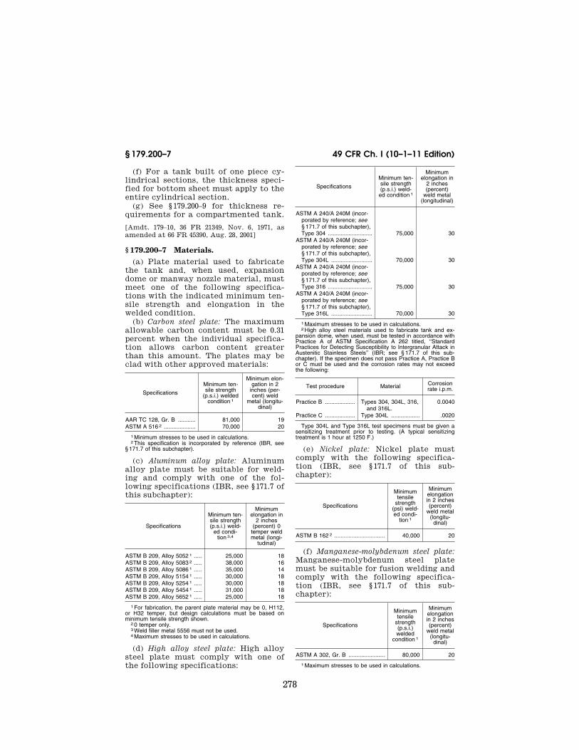
278
49 CFR Ch. I (10–1–11 Edition) § 179.200–7
(f) For a tank built of one piece cy-lindrical sections, the thickness speci-fied for bottom sheet must apply to the entire cylindrical section.
(g) See § 179.200–9 for thickness re-quirements for a compartmented tank.
[Amdt. 179–10, 36 FR 21349, Nov. 6, 1971, as amended at 66 FR 45390, Aug. 28, 2001]
§ 179.200–7 Materials. (a) Plate material used to fabricate
the tank and, when used, expansion dome or manway nozzle material, must meet one of the following specifica-tions with the indicated minimum ten-sile strength and elongation in the welded condition.
(b) Carbon steel plate: The maximum allowable carbon content must be 0.31 percent when the individual specifica-tion allows carbon content greater than this amount. The plates may be clad with other approved materials:
Specifications
Minimum ten-sile strength
(p.s.i.) welded condition 1
Minimum elon-gation in 2
inches (per-cent) weld
metal (longitu-dinal)
AAR TC 128, Gr. B ........... 81,000 19 ASTM A 516 2 .................... 70,000 20
1 Minimum stresses to be used in calculations. 2 This specification is incorporated by reference (IBR, see
§ 171.7 of this subchapter).
(c) Aluminum alloy plate: Aluminum alloy plate must be suitable for weld-ing and comply with one of the fol-lowing specifications (IBR, see § 171.7 of this subchapter):
Specifications
Minimum ten-sile strength (p.s.i.) weld-
ed condi-tion 3,4
Minimum elongation in
2 inches (percent) 0
temper weld metal (longi-
tudinal)
ASTM B 209, Alloy 5052 1 ..... 25,000 18 ASTM B 209, Alloy 5083 2 ..... 38,000 16 ASTM B 209, Alloy 5086 1 ..... 35,000 14 ASTM B 209, Alloy 5154 1 ..... 30,000 18 ASTM B 209, Alloy 5254 1 ..... 30,000 18 ASTM B 209, Alloy 5454 1 ..... 31,000 18 ASTM B 209, Alloy 5652 1 ..... 25,000 18
1 For fabrication, the parent plate material may be 0, H112, or H32 temper, but design calculations must be based on minimum tensile strength shown.
2 0 temper only. 3 Weld filler metal 5556 must not be used. 4 Maximum stresses to be used in calculations.
(d) High alloy steel plate: High alloy steel plate must comply with one of the following specifications:
Specifications
Minimum ten-sile strength (p.s.i.) weld-ed condition 1
Minimum elongation in
2 inches (percent)
weld metal (longitudinal)
ASTM A 240/A 240M (incor-porated by reference; see § 171.7 of this subchapter), Type 304 ............................ 75,000 30
ASTM A 240/A 240M (incor-porated by reference; see § 171.7 of this subchapter), Type 304L .......................... 70,000 30
ASTM A 240/A 240M (incor-porated by reference; see § 171.7 of this subchapter), Type 316 ............................ 75,000 30
ASTM A 240/A 240M (incor-porated by reference; see § 171.7 of this subchapter), Type 316L .......................... 70,000 30
1 Maximum stresses to be used in calculations. 2 High alloy steel materials used to fabricate tank and ex-
pansion dome, when used, must be tested in accordance with Practice A of ASTM Specification A 262 titled, ‘‘Standard Practices for Detecting Susceptibility to Intergranular Attack in Austenitic Stainless Steels’’ (IBR; see § 171.7 of this sub-chapter). If the specimen does not pass Practice A, Practice B or C must be used and the corrosion rates may not exceed the following:
Test procedure Material Corrosion rate i.p.m.
Practice B ................... Types 304, 304L, 316, and 316L.
0.0040
Practice C ................... Type 304L .................. .0020
Type 304L and Type 316L test specimens must be given a sensitizing treatment prior to testing. (A typical sensitizing treatment is 1 hour at 1250 F.)
(e) Nickel plate: Nickel plate must comply with the following specifica-tion (IBR, see § 171.7 of this sub-chapter):
Specifications
Minimum tensile
strength (psi) weld-ed condi-
tion 1
Minimum elongation in 2 inches (percent)
weld metal (longitu-
dinal)
ASTM B 162 2 ................................ 40,000 20
(f) Manganese-molybdenum steel plate: Manganese-molybdenum steel plate must be suitable for fusion welding and comply with the following specifica-tion (IBR, see § 171.7 of this sub-chapter):
Specifications
Minimum tensile
strength (p.s.i.) welded
condition 1
Minimum elongation in 2 inches (percent)
weld metal (longitu-
dinal)
ASTM A 302, Gr. B ....................... 80,000 20
1 Maximum stresses to be used in calculations.
VerDate Mar<15>2010 14:56 Jan 03, 2012 Jkt 223216 PO 00000 Frm 00290 Fmt 8010 Sfmt 8010 Y:\SGML\223216.XXX 223216wre
ier-
avile
s on
DS
K3T
PT
VN
1PR
OD
with
CF
R

279
Pipeline and Hazardous Materials Safety Admin., DOT § 179.200–11
(g) All parts and items of construc-tion in contact with the lading must be made of material compatible with plate material and not subject to rapid deterioration by the lading, or be coat-ed or lined with suitable corrosion re-sistant material.
(h) All external projections that may be in contact with the lading and all castings, forgings, or fabrications used for fittings or attachments to tank and expansion dome, when used, in contact with lading must be made of material to an approved specification. See AAR Specifications for Tank Cars, appendix M, M4.05 (IBR, see § 171.7 of this sub-chapter) for approved material speci-fications for castings for fittings.
[Amdt. 179–10, 36 FR 21349, Nov. 9, 1971; 36 FR 21893, Nov. 17, 1971, as amended by Amdt.179– 28, 46 FR 49906, Oct. 8, 1981; Amdt. 179–40, 52 FR 13046, Apr. 20, 1987; Amdt. 179–52, 61 FR 28680, June 5, 1996; 66 FR 45186, Aug. 28, 2001; 67 FR 51660, Aug. 8, 2002; 68 FR 75761, Dec. 31, 2003; 70 FR 34076, June 13, 2005]
§ 179.200–8 Tank heads. (a) All external tank heads must be
an ellipsoid of revolution in which the major axis must equal the diameter of the shell and the minor axis must be one-half the major axis.
(b) Internal compartment tank heads may be 2:1 ellipsoidal, 3:1 ellipsoidal, or flanged and dished to thicknesses as specified in § 179.200–6. Flanged and dished heads must have main inside ra-dius not exceeding 10 feet, and inside knuckle radius must not be less than 33⁄4 inches for steel, alloy steel, or nick-el tanks, and not less than 5 inches for aluminum alloy tanks.
[Amdt. 179–10, 36 FR 21350, Nov. 6, 1971]
§ 179.200–9 Compartment tanks. (a) When a tank is divided into com-
partments, by inserting interior heads, interior heads must be inserted in ac-cordance with AAR Specifications for Tank Cars, appendix E, E7.00 (IBR, see § 171.7 of this subchapter), and must comply with the requirements specified in § 179.201–1. Voids between compart-ment heads must be provided with at least one tapped drain hole at their lowest point, and a tapped hole at the top of the tank. The top hole must be closed, and the bottom hole may be closed, with not less than three-fourths
inch and not more than 11⁄2-inch solid pipe plugs having NPT threads.
(b) When the tank is divided into compartments by constructing each compartment as a separate tank, these tanks shall be joined together by a cyl-inder made of plate, having a thickness not less than that required for the tank shell and applied to the outside surface of tank head flanges. The cylinder shall fit the straight flange portion of the compartment tank head tightly. The cylinder shall contact the head flange for a distance of at least two times the plate thickness, or a minimum of 1 inch, whichever is greater. The cyl-inder shall be joined to the head flange by a full fillet weld. Distance from head seam to cylinder shall not be less than 11⁄2 inches or three times the plate thickness, whichever is greater. Voids created by the space between heads of tanks joined together to form a com-partment tank shall be provided with a tapped drain hole at their lowest point and a tapped hole at top of tank. The top hole shall be closed and the bottom hole may be closed with solid pipe plugs not less than 3⁄4 inch nor more than 11⁄2 inches having NPT threads.
[29 FR 18995, Dec. 29, 1964. Redesignated at 32 FR 5606, Apr. 5, 1967, and amended by Amdt. 179–10, 36 FR 21350, Nov. 6, 1971; 66 FR 45186, Aug. 28, 2001; 68 FR 75761, Dec. 31, 2003]
§ 179.200–10 Welding.
(a) All joints shall be fusion-welded in compliance with the requirements of AAR Specifications for Tank Cars, ap-pendix W (IBR, see § 171.7 of this sub-chapter). Welding procedures, welders and fabricators shall be approved.
(b) Welding is not permitted on or to ductile iron or malleable iron fittings.
[29 FR 18995, Dec. 29, 1964. Redesignated at 32 FR 5606, Apr. 5, 1967, and amended by Amdt. 179–10, 36 FR 21350, Nov. 6, 1971; 68 FR 75761, Dec. 31, 2003]
§ 179.200–11 Postweld heat treatment.
When specified in § 179.201–1, after welding is complete, postweld heat treatment must be in compliance with the requirements of AAR Specifica-tions for Tank Cars, appendix W (IBR, see § 171.7 of this subchapter).
[68 FR 75761, Dec. 31, 2003]
VerDate Mar<15>2010 14:56 Jan 03, 2012 Jkt 223216 PO 00000 Frm 00291 Fmt 8010 Sfmt 8010 Y:\SGML\223216.XXX 223216wre
ier-
avile
s on
DS
K3T
PT
VN
1PR
OD
with
CF
R

280
49 CFR Ch. I (10–1–11 Edition) § 179.200–13
§ 179.200–13 Manway ring or flange, pressure relief device flange, bot-tom outlet nozzle flange, bottom washout nozzle flange and other at-tachments and openings.
(a) These attachments shall be fusion welded to the tank and reinforced in an approved manner in compliance with the requirements of appendix E, figure 10, of the AAR Specifications for Tank Cars (IBR, see § 171.7 of this sub-chapter).
(b) The opening in the manway ring must be at least 16 inches in diameter except that acid resistant lined manways must be at least 18 inches in diameter before lining.
(c) The manway ring or flange, shall be made of cast, forged or fabricated metal. The metal of the dome, tank, or nozzle must be compatible with the manway ring or flange, so that they may be welded together.
(d) The openings for the manway or other fittings shall be reinforced in an approved manner.
[Amdt. 179–40, 52 FR 13047, Apr. 20, 1987, as amended at 68 FR 75761, Dec. 31, 2003]
§ 179.200–14 Expansion capacity. (a) Tanks shall have expansion capac-
ity as prescribed in this subchapter. This capacity shall be provided in the tank for Class DOT-111A cars, or in a dome for Class DOT-103 and 104 type cars.
(b) For tank cars having an expan-sion dome, the expansion capacity is the total capacity of the tank and dome combined. The capacity of the dome shall be measured from the inside top of shell of tank to the inside top of dome or bottom of any vent pipe pro-jecting inside of dome, except that when a pressure relief device is applied to side of dome, the effective capacity of the dome shall be measured from top of the pressure relief device opening in-side of dome to inside top of shell of tank.
(c) The opening in the tank shell within the dome shall be at least 29 inches in diameter. When the opening in the tank shell exceeds 30 inches in diameter, the opening shall be rein-forced in an approved manner. This ad-ditional reinforcement may be accom-plished by the use of a dome opening of the flued-type as shown in appendix E,
Figure E 10C of the AAR Specifications for Tank Cars or by the use of rein-forcing as outlined in Appendix E, E3.04 and Figures E10K and E10L. When the opening in the tank shell is less than the inside diameter of the dome, and the dome pocket is not closed off in an approved manner, dome pocket drain holes shall be provided in the tank shell with nipples projecting inside the tank at least 1 inch.
(d) The dome head shall be of ap-proved contour and shall be designed for pressure on concave side.
(e) Aluminum alloy domes: (1) The dome shell thickness shall be cal-culated by the formula in § 179.200–6(a).
(2) The dome head may be an ellip-soid of revolution in which the major axis shall be equal to the diameter of the dome shell and the minor axis shall be one-half the major axis. The thick-ness in this case shall be determined by using formula in § 179.200–6(a).
(3) The dome head, if dished, must be dished to a radius not exceeding 96 inches. Thickness of dished dome head must be calculated by the formula in § 179.200–6(c).
(4) Tank shell shall be reinforced by the addition of a plate equal to or greater than shell in thickness and the cross sectional area shall exceed metal removed for dome opening, or tank shell shall be reinforced by a seamless saddle plate equal to or greater than shell in thickness and butt welded to tank shell. The reinforcing saddle plate shall be provided with a fluid opening having a vertical flange of the diame-ter of the dome for butt welding shell of dome to the flange. The reinforcing saddle plate shall extend about the dome a distance measured along shell of tank at least equal to the extension at top of tank. Other approved designs may be used.
[29 FR 18995, Dec. 29, 1964. Redesignated at 32 FR 5606, Apr. 5, 1967, and amended by Amdt. 179–10, 36 FR 21350, Nov. 6, 1971; Amdt. 179–28, 46 FR 49906, Oct. 8, 1981; Amdt. 179–52, 61 FR 28680, June 5, 1996; 66 FR 45186, 45390, Aug. 28, 2001; 68 FR 48571, Aug. 14, 2003]
§ 179.200–15 Closures for manways.
(a) Manway covers must be of ap-proved type.
VerDate Mar<15>2010 14:56 Jan 03, 2012 Jkt 223216 PO 00000 Frm 00292 Fmt 8010 Sfmt 8010 Y:\SGML\223216.XXX 223216wre
ier-
avile
s on
DS
K3T
PT
VN
1PR
OD
with
CF
R

281
Pipeline and Hazardous Materials Safety Admin., DOT § 179.200–16
(b) Manway covers shall be designed to provide a secure closure of the manway.
(c) Manway covers must be of ap-proved cast, forged, or fabricated met-als. Malleable iron, if used, must com-ply with ASTM A 47 (IBR, see § 171.7 of this subchapter), Grade 35018. Cast iron manway covers must not be used.
(d) All joints between manway covers and their seats shall be made tight against leakage of vapor and liquid by use of gaskets of suitable material.
(e) For other manway cover require-ments see § 179.201–1.
[29 FR 18995, Dec. 29, 1964. Redesignated at 32 FR 5606, Apr. 5, 1967, and amended by Amdt. 179–10, 36 FR 21350, Nov. 6, 1971; Amdt. 179–37, 50 FR 11066, Mar. 19, 1985; 68 FR 75762, Dec. 31, 2003]
§ 179.200–16 Gauging devices, top load-ing and unloading devices, venting and air inlet devices.
(a) When installed, these devices shall be of an approved design which will prevent interchange with any other fixture, and be tightly closed. Unloading pipes shall be securely an-chored within the tank. Each tank or compartment may be equipped with one separate air connection.
(b) When the characteristics of the commodity for which the car is author-ized are such that these devices must be equipped with valves or fittings to permit the loading and unloading of the contents, these devices, including valves, shall be of an approved design, and be provided with a protective hous-ing except when plug or ball type valves with operating handles removed are used. Provision shall be made for closing pipe connections of valves.
(c) A tank may be equipped with a vacuum relief valve of an approved de-sign. Protective housing is not re-quired.
(d) When using a visual gauging de-vice on a car with a hinged manway cover, an outage scale visible through the manway opening shall be provided. If loading devices are applied to permit tank loading with cover closed, a tell-tale pipe may be provided. Telltale pipe shall be capable of determining that re-quired outage is provided. Pipe shall be equipped with 1⁄4 inch minimum NPT control valve mounted outside tank
and enclosed within a housing. Other approved devices may be used in lieu of outage scale or telltale pipe.
(e) Bottom of tank shell may be equipped with a sump or siphon bowl, or both, welded or pressed into the shell. Such sumps or siphon bowls, if applied are not limited in size and must be made of cast, forged, or fab-ricated metal. Each sump or siphon bowl must be of good welding quality in conjunction with the metal of the tank shell. When sump or siphon bowl is pressed in the bottom of the tank shell, the wall thickness of the pressed section must not be less than that specified for the shell. The section of a circular cross section tank to which a sump or siphon bowl is attached need not comply with the out-of-roundness requirement specified in appendix W, W14.06, of the AAR Specifications for Tank Cars. Any portion of a sump or si-phon bowl not forming a part of a cyl-inder of revolution must have walls of such thickness and be so reinforced that the stresses in the walls caused by a given internal pressure are not great-er than the circumferential stress which would exist under the same in-ternal pressure in the wall of a tank of circular cross section designed in ac-cordance with § 179.200–6 (a) and (d). In no case shall the wall thickness be less than that specified in § 179.201–1.
(f) When top loading and discharge devices, or venting and air inlet de-vices are installed with exposed piping to a removed location, shutoff valves must be applied directly to reinforcing pads or nozzles at their communication through the tank shell, and must be enclosed in a protective housing with provision for a seal. The piping must include breakage grooves, and suitable bracing. Relief valves must be applied to liquid lines for protection in case lading is trapped. Provision must be made to insure closure of the valves while the car is in transit.
(g) Protective housing, when re-quired, must be fabricated of approved material and have cover and sidewalls not less than 0.119 inch in thickness.
[29 FR 18995, Dec. 29, 1964. Redesignated at 32 FR 5606, Apr. 5, 1967, and amended by Amdt. 179–10, 36 FR 21350, Nov. 6, 1971; Amdt. 179–52, 61 FR 28680, June 5, 1996; 69 FR 54047, Sept. 7, 2004]
VerDate Mar<15>2010 14:56 Jan 03, 2012 Jkt 223216 PO 00000 Frm 00293 Fmt 8010 Sfmt 8010 Y:\SGML\223216.XXX 223216wre
ier-
avile
s on
DS
K3T
PT
VN
1PR
OD
with
CF
R

282
49 CFR Ch. I (10–1–11 Edition) § 179.200–17
§ 179.200–17 Bottom outlets. (a) If indicated in § 179.201–1, tank
may be equipped with bottom outlet. Bottom outlet, if applied, must comply with the following requirements:
(1) The extreme projection of the bot-tom outlet equipment may not be more than that allowed by appendix E of the AAR Specifications for Tank Cars (IBR, see § 171.7 of this subchapter). All bottom outlet reducers and closures and their attachments shall be secured to the car by at least 3⁄8-inch chain, or its equivalent, except that the bottom outlet closure plugs may be attached by 1⁄4-inch chain. When the bottom out-let closure is of the combination cap and valve type, the pipe connection to the valve shall be closed by a plug, cap, or approved quick coupling device. The bottom outlet equipment should in-clude only the valve, reducers and clo-sures that are necessary for the attach-ment of unloading fixtures. The perma-nent attachment of supplementary ex-terior fittings shall be approved by the AAR Committee on Tank Cars.
(2) Bottom outlet must be of ap-proved construction, and be provided with a liquid-tight closure at its lower end.
(3) On cars with center sills, a ball valve may be welded to the outside bot-tom of the tank or mounted on a pad or nozzle with a tongue and groove or male and female flange attachment. In no case shall the breakage groove or equivalent extend below the bottom flange of the center sill. On cars with-out continuous center sills, a ball valve may be welded to the outside bottom of the tank or mounted with a tongue and groove or male and female flange at-tachment on a pad attached to the out-side bottom of the tank. The mounting pad must have a maximum thickness of 21⁄2 inches measured on the longitu-dinal centerline of the tank. The valve operating mechanism must be provided with a suitable locking arrangement to insure positive closure during transit.
(4) The valve operating mechanism for valves applied to the interior of the tank, and outlet nozzle construction, must insure against the unseating of the valve due to stresses or shocks in-cident to transportation.
(5) Bottom outlet nozzle of interior valves and the valve body of exterior
valves, must be of cast, fabricated, or forged metal. If welded to tank, they must be of good weldable quality in conjunction with metal of tank.
(6) To provide for the attachment of unloading connections, the discharge end of the bottom outlet nozzle or re-ducer, the valve body of the exterior valve, or some fixed attachment there-to, shall be provided with one of the following arrangements or an approved modification thereof. (See appendix E. Fig. E17 of the AAR Specifications for Tank Cars for illustrations of some of the possible arrangements.)
(i) A bolted flange closure arrange-ment including a minimum 1-inch NPT pipe plug (see Fig. E17.1) or including an auxiliary valve with a threaded clo-sure.
(ii) A threaded cap closure arrange-ment including a minimum 1-inch NPT pipe plug (see Fig. E17.2) or including an auxiliary valve with a threaded clo-sure.
(iii) A quick-coupling device using a threaded plug closure of at least 1-inch NPT or having a threaded cap closure with a minimum 1-inch NPT pipe plug (see Fig. E17.3 through E17.5). A min-imum 1-inch auxiliary test valve with a threaded closure may be substituted for the 1-inch pipe plug (see Fig. E17.6). If the threaded cap closure does not have a pipe plug or integral auxiliary test valve, a minimum 1-inch NPT pipe plug shall be installed in the outlet nozzle above the closure (see Fig. E17.7).
(iv) A two-piece quick-coupling de-vice using a clamped dust cap must in-clude an in-line auxiliary valve, either integral with the quick-coupling device or located between the primary bottom outlet valve and the quick-coupling de-vice. The quick-coupling device closure dust cap or outlet nozzle shall be fitted with a minimum 1-inch NPT closure (see Fig. E17.8 and E17.9).
(7) If the outlet nozzle extends 6 inches or more from the shell of the tank, a V-shaped breakage groove shall be cut (not cast) in the upper part of the outlet nozzle at a point imme-diately below the lowest part of valve closest to the tank. In no case may the nozzle wall thickness at the root of the ‘‘V’’ be more than 1⁄4 inch. The outlet nozzle on interior valves or the valve
VerDate Mar<15>2010 14:56 Jan 03, 2012 Jkt 223216 PO 00000 Frm 00294 Fmt 8010 Sfmt 8010 Y:\SGML\223216.XXX 223216wre
ier-
avile
s on
DS
K3T
PT
VN
1PR
OD
with
CF
R

283
Pipeline and Hazardous Materials Safety Admin., DOT § 179.200–19
body on exterior valves may be steam jacketed, in which case the breakage groove or its equivalent must be below the steam chamber but above the bot-tom of center sill construction. If the outlet nozzle is not a single piece, or if exterior valves are applied, provisions shall be made for the equivalent of the breakage groove. On cars without con-tinuous center sills, the breakage groove or its equivalent must be no more than 15 inches below the tank shell. On cars with continuous center sills, the breakage groove or its equiva-lent must be above the bottom of the center sill construction.
(8) The flange on the outlet nozzle or the valve body of exterior valves must be of a thickness which will prevent distortion of the valve seat or valve by any change in contour of the shell re-sulting from expansion of lading, or other causes, and which will insure that accidental breakage of the outlet nozzle will occur at or below the ‘‘V’’ groove, or its equivalent.
(9) The valve must have no wings or stem projecting below the ‘‘V’’ groove or its equivalent. The valve and seat must be readily accessible or remov-able for repairs, including grinding.
(10) The valve operating mechanism on interior valves must have means for compensating for variation in the vertical diameter of the tank produced by expansion, weight of the liquid con-tents, or other causes, and may operate from the interior of the tank, but in the event the rod is carried through the dome, or tank shell, leakage must be prevented by packing in stuffing box or other suitable seals and a cap.
(b) If indicated in § 179.201–1, tank may be equipped with bottom washout of approved construction. If applied, bottom washout shall be in accordance with the following requirements:
(1) The extreme projection of the bot-tom washout equipment may not be more than that allowed by appendix E of the AAR Specifications for Tank Cars.
(2) Bottom washout shall be of cast, forged or fabricated metal. If welded to tank, they shall be of good weldable quality in conjunction with metal of tank.
(3) If the washout nozzle extends 6 inches or more from the shell of the
tank, a V-shaped breakage groove shall be cut (not cast) in the upper part of the nozzle at a point immediately below the lowest part of the inside clo-sure seat or plug. In no case may the nozzle wall thickness at the root of the ‘‘V’’ be more than 1⁄4 inch. Where the nozzle is not a single piece, provisions shall be made for the equivalent of the breakage groove. The nozzle must be of a thickness to insure that accidental breakage will occur at or below the ‘‘V’’ groove or its equivalent. On cars without continuous center sills, the breakage groove or its equivalent may not be more than 15 inches below the outer shell. On cars with continuous center sills, the breakage groove or its equivalent must be above the bottom of the center sill construction.
(4) The closure plug and seat must be readily accessible or removable for re-pairs, including grinding.
(5) The closure of the washout nozzle must be equipped with a 3⁄4-inch solid screw plug. Plug must be attached by at least a 1⁄4-inch chain.
(6) Joints between closures and their seats may be gasketed with suitable material.
[29 FR 18995, Dec. 29, 1964. Redesignated at 32 FR 5606, Apr. 5, 1967, and amended by Amdt. 179–10, 36 FR 21351, Nov. 6, 1971; Amdt. 179–40, 52 FR 13047, Apr. 20, 1987; 68 FR 75762, Dec. 31, 2003]
§ 179.200–19 Reinforcements, when used, and appurtenances not other-wise specified.
(a) All attachments to tank and dome shall be applied by approved means. Rivets if used shall be caulked inside and outside.
(b) Reinforcing pads must be used be-tween external brackets and shells if the attachment welds exceed 6 lineal inches of 1⁄4-inch fillet or equivalent weld per bracket or bracket leg. When reinforcing pads are used, they must not be less than one-fourth inch in thickness, have each corner rounded to a 1 inch minimum radius, and be at-tached to the tank by continuous fillet welds except for venting provisions. The ultimate shear strength of the bracket to reinforcing pad weld must not exceed 85 percent of the ultimate
VerDate Mar<15>2010 14:56 Jan 03, 2012 Jkt 223216 PO 00000 Frm 00295 Fmt 8010 Sfmt 8010 Y:\SGML\223216.XXX 223216wre
ier-
avile
s on
DS
K3T
PT
VN
1PR
OD
with
CF
R

284
49 CFR Ch. I (10–1–11 Edition) § 179.200–21
shear strength of the reinforcing pad to tank weld.
[29 FR 18995, Dec. 29, 1964. Redesignated at 32 FR 5606, Apr. 5, 1967, and amended by Amdt. 179–10, 36 FR 21351, Nov. 6, 1971]
§ 179.200–21 Closures for openings. (a) All plugs shall be solid, with NPT
threads, and shall be of a length which will screw at least 6 threads inside the face of fitting or tank. Plugs, when in-serted from the outside of tank heads, shall have the letter ‘‘S’’ at least 3⁄8 inch in size stamped with steel stamp or cast on the outside surface to indi-cate the plug is solid.
(b) [Reserved]
§ 179.200–22 Test of tanks. (a) Each tank shall be tested by com-
pletely filling the tank and dome or nozzles with water, or other liquid hav-ing similar viscosity, of a temperature which shall not exceed 100 °F. during the test; and applying the pressure pre-scribed in § 179.201–1. Tank shall hold the prescribed pressure for at least 10 minutes without leakage or evidence of distress. All rivets and closures, except safety relief valves or safety vents, shall be in place when test is made.
(b) Insulated tanks shall be tested be-fore insulation is applied.
(c) Rubber-lined tanks shall be tested before rubber lining is applied.
(d) Caulking of welded joints to stop leaks developed during the foregoing tests is prohibited. Repairs in welded joints shall be made as prescribed in AAR Specifications for Tank Cars, ap-pendix W (IBR, see § 171.7 of this sub-chapter).
[29 FR 18995, Dec. 29, 1964, as amended at 68 FR 75762, Dec. 31, 2003]
§ 179.200–23 Tests of pressure relief valves.
(a) Each valve shall be tested by air or gas for compliance with § 179.15 be-fore being put into service.
(b) [Reserved]
[29 FR 18995, Dec. 29, 1964. Redesignated at 32 FR 5606, Apr. 5, 1967, as amended at 62 FR 51561, Oct. 1, 1997]
§ 179.200–24 Stamping.
(a) To certify that the tank complies with all specification requirements, each tank shall be plainly and perma-nently stamped in letters and figures at least 3⁄8 inch high into the metal near the center of both outside heads as follows:
Example of required stamping
Specification ................................. DOT-111A Material ......................................... ASTM A 516–GR 70 Cladding material (if any) ............. ASTM A240–304 Clad Tank builder’s initials .................... ABC Date of original test ...................... 00–0000 Car assembler (if other than tank
builder).DEF
(b) On Class DOT-111 tank cars, the last numeral of the specification num-ber may be omitted from the stamping; for example, DOT-111A100W.
[29 FR 18995, Dec. 29, 1964. Redesignated at 32 FR 5606, Apr. 5, 1967, and amended by Amdt. 179–10, 36 FR 21351, Nov. 6, 1971; Amdt. 179–52, 61 FR 28680, June 5, 1996; 68 FR 48571, Aug. 14, 2003]
§ 179.201 Individual specification re-quirements applicable to non-pres-sure tank car tanks.
§ 179.201–1 Individual specification requirements. In addition to § 179.200, the individual specification requirements are as follows:
DOT Specifica-tion 1 Insulation
Bursting pressure
(psig)
Minimum plate
thickness (inches)
Test pressure
(psig)
Bottom outlet
Bottom washout
References (179.201 - ***)
111A60ALW1 ... Optional .......... 240 1⁄2 60 Optional .......... Optional .......... 6(a). 111A60ALW2 ... Optional .......... 240 1⁄2 60 No ................... Optional. 111A60W1 ....... Optional .......... 240 7⁄16 60 Optional .......... Optional .......... 6(a). 111A60W2 ....... Optional .......... 240 7⁄16 60 No ................... Optional. 111A60W5 ....... Optional .......... 240 7⁄16 60 No ................... No ................... 3, 6(b). 111A60W6 ....... Optional .......... 240 7⁄16 60 Optional .......... Optional .......... 4, 5, 6(a), 6(c). 111A60W7 ....... Optional .......... 240 7⁄16 60 No ................... No ................... 4, 5, 6(a). 111A100ALW1 Optional .......... 500 5⁄8 100 Optional .......... Optional .......... 6(a).
VerDate Mar<15>2010 14:56 Jan 03, 2012 Jkt 223216 PO 00000 Frm 00296 Fmt 8010 Sfmt 8010 Y:\SGML\223216.XXX 223216wre
ier-
avile
s on
DS
K3T
PT
VN
1PR
OD
with
CF
R

285
Pipeline and Hazardous Materials Safety Admin., DOT § 179.201–3
DOT Specifica-tion 1 Insulation
Bursting pressure
(psig)
Minimum plate
thickness (inches)
Test pressure
(psig)
Bottom outlet
Bottom washout
References (179.201 - ***)
111A100ALW2 Optional .......... 500 5⁄8 100 No ................... Optional. 111A100W1 ..... Optional .......... 500 7⁄16 100 Optional .......... Optional .......... 6(a). 111A100W2 ..... Optional .......... 500 7⁄16 100 No ................... Optional. 111A100W3 ..... Yes ................. 500 7⁄16 100 Optional .......... Optional .......... 6(a). 111A100W4 ..... Yes (see
179.201–11).500 7⁄16 100 No ................... No ................... 6(a), 8, 10.
111A100W5 ..... Optional .......... 500 7⁄16 100 No ................... No ................... 3. 111A100W6 ..... Optional .......... 500 7⁄16 100 Optional .......... Optional .......... 4, 5, 6(a) and 6(c). 111A100W7 ..... Optional .......... 500 7⁄16 100 No ................... No ................... 4, 5, 6(c).
1 Tanks marked ‘‘ALW’’ are constructed from aluminum alloy plate; ‘‘AN’’ nickel plate; ‘‘CW,’’ ‘‘DW,’’ ‘‘EW,’’ ‘‘W6,’’ and ‘‘W7’’ high alloy steel or manganese-molybdenum steel plate; and those marked ‘‘BW’’ or ‘‘W5’’ must have an interior lining that con-forms to § 179.201–3.
[Amdt. 179–52, 61 FR 28680, June 5, 1996, as amended by 66 FR 45390, Aug. 28, 2001; 68 FR 48571, Aug. 14, 2003]
§ 179.201–2 [Reserved]
§ 179.201–3 Lined tanks. (a) Rubber-lined tanks. (1) Each tank
or each compartment thereof must be lined with acid-resistant rubber or other approved rubber compound vul-canized or bonded directly to the metal tank, to provide a nonporous laminated lining, at least 5⁄32-inch thick, except overall rivets and seams formed by riv-eted attachments in the lining must be double thickness. The rubber lining must overlap at least 11⁄2 inches at all edges which must be straight and be beveled to an angle of approximately 45°, or butted edges of lining must be sealed with a 3-inch minimum strip of lining having 45° beveled edges.
(2) As an alternate method, the lining may be joined with a skived butt seam then capped with a separate strip of lining 3 inches wide having 45° beveled edges. An additional rubber reinforcing pad at least 41⁄2 feet square and at least 1⁄2-inch thick must be applied by vul-canizing to the lining on bottom of tank directly under the manway open-ing. The edges of the rubber pad must be beveled to an angle of approxi-mately 45°. An opening in this pad for sump is permitted. No lining must be under tension when applied except due to conformation over rivet heads. Inte-rior of tank must be free from scale, oxidation, moisture, and all foreign matter during the lining operation.
(3) Other approved lining materials may be used provided the material is resistant to the corrosive or solvent ac-tion of the lading in the liquid or gas
phase and is suitable for the service temperatures.
(b) Before a tank car tank is lined with rubber, or other rubber compound, a report certifying that the tank and its equipment have been brought into compliance with spec. DOT-111A60W5 or 111A100W5 must be furnished by car owner to the party who is to apply the lining. A copy of this report in ap-proved form, certifying that tank has been lined in compliance with all re-quirements of one of the above speci-fications, must be furnished by party lining tank to car owner. Reports of the latest lining application must be retained by the car owner until the next relining has been accomplished and recorded.
(c) All rivet heads on inside of tank must be buttonhead, or similar shape, and of uniform size. The under surface of heads must be driven tight against the plate. All plates, castings and rivet heads on the inside of the tank must be calked. All projecting edges of plates, castings and rivet heads on the inside of the tank must be rounded and free from fins and other irregular projec-tions. Castings must be free from po-rosity.
(d) All surfaces of attachments or fit-tings and their closures exposed to the lading must be covered with at least 1⁄8- inch acid resistant material. Attach-ments made of metal not affected by the lading need not be covered with rubber or other acid resistant material.
(e) Hard rubber or polyvinyl chloride may be used for pressure retaining
VerDate Mar<15>2010 14:56 Jan 03, 2012 Jkt 223216 PO 00000 Frm 00297 Fmt 8010 Sfmt 8010 Y:\SGML\223216.XXX 223216wre
ier-
avile
s on
DS
K3T
PT
VN
1PR
OD
with
CF
R

286
49 CFR Ch. I (10–1–11 Edition) § 179.201–4
parts of safety vents provided the ma-terial is resistant to the corrosive or solvent action of the lading in the liq-uid or gas phase and is suitable for the service temperatures.
(f) Polyvinyl chloride lined tanks. Tank car tanks or each compartment thereof may be lined with elastomeric polyvinyl chloride having a minimum lining thickness of three thirty-seconds inch.
(g) Polyurethane lined tanks. Tank car tanks or each compartment thereof may be lined with elastomeric poly-urethane having a minimum lining thickness of one-sixteenth inch.
[Amdt. 179–10, 36 FR 21352, Nov. 6, 1971, as amended at 66 FR 45186, Aug. 28, 2001; 68 FR 48571, Aug. 14, 2003]
§ 179.201–4 Material.
All fittings, tubes, and castings and all projections and their closures, ex-cept for protective housing, must also meet the requirements specified in ASTM A 262 (IBR, see § 171.7 of this sub-chapter), except that when preparing the specimen for testing the carburized surface may be finished by grinding or machining.
[68 FR 75762, Dec. 31, 2003]
§ 179.201–5 Postweld heat treatment and corrosion resistance.
(a) Tanks and attachments welded di-rectly thereto must be postweld heat treated as a unit at the proper tem-perature except as indicated below. Tanks and attachments welded directly thereto fabricated from ASTM A 240/A 240M (IBR, see § 171.7 of this sub-chapter) Type 430A, Type 304 and Type 316 materials must be postweld heat treated as a unit and must be tested to demonstrate that they possess the cor-rosion resistance specified in § 179.200– 7(d), Footnote 2. Tanks and attach-ments welded directly thereto, fab-ricated from ASTM A 240/A 240M Type 304L or Type 316L materials are not re-quired to be postweld heat treated.
(b) Tanks and attachments welded di-rectly thereto, fabricated from ASTM A 240/A 240M Type 304L and Type 316 materials must be tested to dem-onstrate that they possess the corro-
sion resistance specified in § 179.200– 7(d), Footnote 2.
[68 FR 75762, Dec. 31, 2003]
§ 179.201–6 Manways and manway clo-sures.
(a) The manway cover for spec. DOT 104W, 111A60–ALW1, 111A60W1, 111A100ALW1, 111A–100W1, 111A100W3, or 111A100W6 must be designed to make it impossible to remove the cover while the interior of the tank is subjected to pressure.
(b) The manway cover for spec. DOT 11A60W5, or 111A100W5 must be made of a suitable metal. The top, bottom and edge of manway cover must be acid re-sistant material covered as prescribed in § 179.201–3. Through-bolt holes must be lined with acid resistant material at least one-eighth inch in thickness. Cover made of metal not affected by the lading need not be acid resistant material covered.
(c) The manway ring and cover for specifications DOT-103CW, 103DW, 103EW, 111360W7, or 11A100W6 must be made of the metal and have the same inspection procedures specified in AAR Specifications for Tank Cars, appendix M, M3.03 (IBR, see § 171.7 of this sub-chapter).
[Amdt. 179–10, 36 FR 21353, Nov. 6, 1971; 66 FR 45186, Aug. 28, 2001; 68 FR 48571, Aug. 14, 2003; 68 FR 75762, Dec. 31, 2003]
§ 179.201–8 Sampling device and ther-mometer well.
(a) Sampling valve and thermometer well are not specification require-ments. When used, they must be of ap-proved design, made of metal not sub-ject to rapid deterioration by lading, and must withstand a pressure of 100 psig without leakage. Interior pipes of the sampling valve must be equipped with excess flow valves of an approved design. Interior pipe of thermometer well must be closed by an approved valve attached close to fitting where it passes through the tank and closed by a screw plug. Other approved arrange-ments that permit testing thermom-eter well for leaks without complete removal of the closure may be used.
(b) [Reserved]
[Amdt. 179–10, 36 FR 21348, Nov. 6, 1971, as amended at 66 FR 45390, Aug. 28, 2001]
VerDate Mar<15>2010 14:56 Jan 03, 2012 Jkt 223216 PO 00000 Frm 00298 Fmt 8010 Sfmt 8010 Y:\SGML\223216.XXX 223216wre
ier-
avile
s on
DS
K3T
PT
VN
1PR
OD
with
CF
R

287
Pipeline and Hazardous Materials Safety Admin., DOT § 179.220–6
§ 179.201–9 Gauging device.
A gauging device of an approved de-sign must be applied to permit deter-mining the liquid level of the lading. The gauging device must be made of materials not subject to rapid deterio-ration by the lading. When the interior pipe of the gauging device provides a means for passage of the lading from the interior to the exterior of the tank, it must be equipped with an excess flow valve of an approved design. If the opening for passage of lading through the gauging device is not more than 0.060 inch diameter an excess flow valve is not required. The gauging device must be provided with a protective housing.
[Amdt. 179–10, 36 FR 21353, Nov. 6, 1971]
§ 179.201–10 Water capacity marking.
(a) Water capacity of the tank in pounds stamped plainly and perma-nently in letters and figures at least 3⁄8 inch high into the metal of the tank immediately below the stamped marks specified in § 179.200–24(a). This mark shall also be stenciled on the jacket immediately below the dome platform and directly behind or within 3 feet of the right or left side of the ladder, or ladders, if there is a ladder on each side of the tank, in letters and figures at least 11⁄2 inches high as follows:
WATER CAPACITY
000000 Pounds
(b) [Reserved]
§ 179.201–11 Insulation.
(a) Insulation shall be of sufficient thickness so that the thermal conduct-ance at 60 °F. is not more than 0.075 Btu per hour, per square foot, per de-gree F. temperature differential.
(b) [Reserved]
§§ 179.202—179.202–22 [Reserved]
§ 179.220 General specifications appli-cable to nonpressure tank car tanks consisting of an inner container supported within an outer shell (class DOT-115).
§ 179.220–1 Tanks built under these specifications must meet the re-quirements of §§ 179.220 and 179.221.
§ 179.220–3 Type.
(a) Tanks built under these specifica-tions must consist of an inner con-tainer, a support system for the inner container, and an outer shell.
(b) The inner container must be a fu-sion welded tank of circular cross sec-tion with formed heads designed con-vex outward and must have a manway on top of the tank as prescribed herein. When the inner container is divided into compartments, each compartment must be considered a separate con-tainer.
(c) The outer shell must be a fusion welded tank with formed heads de-signed convex outward.
[Amdt. 179–9, 36 FR 21340, Nov. 6, 1971]
§ 179.220–4 Insulation.
The annular space between the inner container and the outer shell must con-tain an approved insulation material.
[Amdt. 179–9, 36 FR 21340, Nov. 6, 1971]
§ 179.220–6 Thickness of plates.
(a) The wall thickness, after forming of the inner container shell and 2:1 el-lipsoidal heads must be not less than specified in § 179.221–1, or not less than that calculated by the following for-mula:
t =Pd
SE2Where:
d = Inside diameter in inches; E = 0.9 welded joint efficiency; except E=1.0
for seamless heads; P = Minimum required bursting pressure in
psig; S = Minimum tensile strength of plate mate-
rial in p.s.i. as prescribed in AAR Speci-fications for Tank Cars, appendix M, Table M1;
VerDate Mar<15>2010 14:56 Jan 03, 2012 Jkt 223216 PO 00000 Frm 00299 Fmt 8010 Sfmt 8010 Y:\SGML\223216.XXX 223216 EC
13N
O91
.035
</M
AT
H>
wre
ier-
avile
s on
DS
K3T
PT
VN
1PR
OD
with
CF
R

288
49 CFR Ch. I (10–1–11 Edition) § 179.220–7
t = Minimum thickness of plate in inches after forming.
(b) The wall thickness after forming of the inner container heads, if flanged and dished, must be not less than speci-fied in § 179.221–1, or not less than that calculated by the following formula:
t =PL
SE
5
6Where:
E = 0.9 welded joint efficiency; except E=1.0 for seamless heads;
L = Main inside radius to which head is dished, measured on concave side in inches;
P = Minimum required bursting pressure in psig;
S = Minimum tensile strength of plate mate-rial in psi as prescribed in AAR Specifica-tions for Tank Cars, appendix M, Table M1 (IBR, see § 171.7 of this subchapter);
t = Minimum thickness of plate in inches after forming.
(c) The wall thickness after forming of the cylindrical section and heads of the outer shell must be not less than seven-sixteenths of an inch.
(d) See § 179.220–9 for plate thickness requirements for inner container when divided into compartments.
[Amdt. 179–9, 36 FR 21340, Nov. 6, 1971, as amended at 66 FR 45390, Aug. 28, 2001; 68 FR 75762, Dec. 31, 2003]
§ 179.220–7 Materials. (a) The plate material used to fab-
ricate the inner container and nozzles must meet one of the following speci-fications and with the indicated min-imum tensile strength and elongation in the welded condition.
(b) Carbon steel plate: The maximum allowable carbon content must be 0.31 percent when the individual specifica-tion allows carbon content greater than this amount. The plates may be clad with other approved materials.
Specifications
Minimum tensile
strength (p.s.i.) welded
condition 1
Minimum elongation in 2 inches (percent)
weld metal (longitu-
dinal)
AAR TC 128, Gr. B ....................... 81,000 19 ASTM A 516 2, Gr. 70 ................... 70,000 20
1 Maximum stresses to be used in calculations.
2 This specification is incorporated by reference (IBR, see § 171.7 of this subchapter).
(c) Aluminum alloy plate: Aluminum alloy plate must be suitable for weld-ing and comply with one of the fol-lowing specifications (IBR, see § 171.7 of this subchapter): * * *
Specifications
Minimum tensile
strength (p.s.i.) welded
condition3,4
Minimum elongation in 2 inches (percent)
weld metal (longitu-
dinal)
ASTM B 209, Alloy 5052 1 ............. 25,000 18 ASTM B 209, Alloy 5083 2 ............. 38,000 16 ASTM B 209, Alloy 5086 1 ............. 35,000 14 ASTM B 209, Alloy 5154 1 ............. 30,000 18 ASTM B 209, Alloy 5254 1 ............. 30,000 18 ASTM B 209, Alloy 5454 1 ............. 31,000 18 ASTM B 209, Alloy 5652 1 ............. 25,000 18
1 For fabrication, the parent plate material may be 0 H112, or H32 temper, but design calculations must be based on the minimum tensile strength shown.
2 0 temper only. 3 Weld filler metal 5556 must not be used. 4 Maximum stresses to be used in calculations.
(d) High alloy steel plate: High alloy steel plate must comply with one of the following specifications (IBR, see § 171.7 of this subchapter):
Specifications
Minimum tensile
strength (p.s.i.) welded
condition1
Minimum elongation in 2 inches (percent)
weld metal (longitu-
dinal)
ASTM A 240/A 240M (incor-porated by reference; see § 171.7 of this subchapter), Type 304 .................................... 75,000 30
ASTM A 240/A 240M (incor-porated by reference; see § 171.7 of this subchapter), Type 304L .................................. 70,000 30
ASTM A 240/A 240M (incor-porated by reference; see § 171.7 of this subchapter), Type 316 .................................... 74,000 30
ASTM A 240/A 240M (incor-porated by reference; see § 171.7 of this subchapter), Type 316L .................................. 70,000 30
1 Maximum stresses to be used in calculations.
(e) Manganese-molybdenum steel plate: Manganese-molybdenum steel plate must be suitable for fusion weld-ing and must comply with the fol-lowing specification (IBR, see § 171.7 of this subchapter):
VerDate Mar<15>2010 14:56 Jan 03, 2012 Jkt 223216 PO 00000 Frm 00300 Fmt 8010 Sfmt 8010 Y:\SGML\223216.XXX 223216 EC
13N
O91
.036
</M
AT
H>
wre
ier-
avile
s on
DS
K3T
PT
VN
1PR
OD
with
CF
R

289
Pipeline and Hazardous Materials Safety Admin., DOT § 179.220–11
Specifications
Minimum tensile
strength (p.s.i.) welded
condition 1
Minimum elongation in 2 inches (percent)
weld metal (longitu-
dinal)
ASTM A 302, Gr. B ....................... 80,000 20
1 Maximum stresses to be used in calculations.
(f) Plate materials used to fabricate the outer shell and heads must be those listed in paragraphs (b), (c), (d), or (e) of this section. The maximum allow-able carbon content must be 0.31 per-cent when the individual specification allows carbon content greater than this amount. The plates may be clad with other approved materials.
(g) All appurtenances on the inner container in contact with the lading must be made of approved material compatible with the plate material of the inner container. These appur-tenances must not be subject to rapid deterioration by the lading, or must be coated or lined with suitable corrosion resistant material. See AAR Specifica-tions for Tank Cars, appendix M, M4.05 for approved material specifications for castings for fittings.
[Amdt. 179–9, 36 FR 21340, Nov. 6, 1971, as amended by Amdt. 179–28, 46 FR 49906, Oct. 8, 1981; Amdt. 179–40, 52 FR 13048, Apr. 20, 1987; Amdt. 179–52, 61 FR 28681, June 5, 1996; 66 FR 45186, Aug. 28, 2001; 67 FR 51660, Aug. 8, 2002; 68 FR 75762, Dec. 31, 2003]
§ 179.220–8 Tank heads.
(a) Tank heads of the inner con-tainer, inner container compartments and outer shell must be of approved contour, and may be flanged and dished or ellipsoidal for pressure on concave side.
(b) Flanged and dished heads must have main inside radius not exceeding 10 feet and inside knuckle radius must be not less than 33⁄4 inches for steel and alloy steel tanks nor less than 5 inches for aluminum alloy tanks.
(c) Ellipsoidal heads must be an ellip-soid of revolution in which the major axis must equal the diameter of the shell and the minor axis must be one- half the major axis.
[Amdt. 179–9, 36 FR 21341, Nov. 6, 1971]
§ 179.220–9 Compartment tanks.
(a) The inner container may be di-vided into compartments by inserting interior heads, or by fabricating each compartment as a separate container and joining with a cylinder, or by fabri-cating each compartment as a separate tank without a joining cylinder. Each compartment must be capable of with-standing, without evidence of yielding or leakage, the required test pressure applied in each compartment sepa-rately, or in any combination of com-partments.
(b) When the inner container is di-vided into compartments by fabri-cating each compartment as a separate container and joining with a cylinder, the cylinder must have a plate thick-ness not less than that required for the inner container shell and must be ap-plied to the outside surface of the straight flange portion of the container head. The cylinder must fit the straight flange tightly for a distance of at least two times the plate thickness, or 1 inch, whichever is greater and must be joined to the straight flange by a full fillet weld. Distance from fil-let weld seam to container head seam must be not less than 11⁄2 inches or three times the plate thickness, which-ever is greater.
[Amdt. 179–9, 36 FR 21341, Nov. 6, 1971]
§ 179.220–10 Welding.
(a) All joints must be fusion welded in compliance with AAR Specifications for Tank Cars, appendix W (IBR, see § 171.7 of this subchapter). Welding pro-cedures, welders, and fabricators shall be approved.
(b) Radioscopy of the outer shell is not a specification requirement.
(c) Welding is not permitted on or to ductile iron or malleable iron fittings.
[Amdt. 179–9, 36 FR 21341, Nov. 6, 1971, as amended at 68 FR 75762, Dec. 31, 2003]
§ 179.220–11 Postweld heat treatment.
(a) Postweld heat treatment of the inner container is not a specification requirement.
(b) Postweld heat treatment of the cylindrical portions of the outer shell to which the anchorage or draft sills are attached must comply with AAR
VerDate Mar<15>2010 14:56 Jan 03, 2012 Jkt 223216 PO 00000 Frm 00301 Fmt 8010 Sfmt 8010 Y:\SGML\223216.XXX 223216wre
ier-
avile
s on
DS
K3T
PT
VN
1PR
OD
with
CF
R

290
49 CFR Ch. I (10–1–11 Edition) § 179.220–13
Specifications for Tank Cars, appendix W (IBR, see § 171.7 of this subchapter).
(c) When cold formed heads are used on the outer shell they must be heat treated before welding to shell if postweld heat treatment is not prac-ticable due to assembly procedures.
[Amdt. 179–9, 36 FR 21341, Nov. 6, 1971, as amended at 68 FR 75762, Dec. 31, 2003]
§ 179.220–13 Inner container manway nozzle and cover.
(a) Inner container manway nozzle must be of approved design with access opening at least 18 inches inside diame-ter, or at least 14 inches by 18 inches obround or oval.
(b) Manway covers must be of ap-proved type. Design must provide a se-cure closure of the manway and must make it impossible to remove the cover while the tank interior is under pres-sure.
(c) All joints between manway covers and their seats must be made tight against leakage of vapor and liquid by use of suitable gaskets.
(d) Manway covers must be cast, forged, or fabricated metal complying with subsection § 179.220–7(g) of this section.
(e) A seal must be provided between the inner container manway nozzle and the opening in the outer shell.
[Amdt. 179–9, 36 FR 21341, Nov. 6, 1971]
§ 179.220–14 Openings in the tanks. Openings in the inner container and
the outer shell must be reinforced in compliance with AAR Specifications for Tank Cars, appendix E (IBR, see § 171.7 of this subchapter). In deter-mining the required reinforcement area for openings in the outer shell, t shall be one-fourth inch.
[68 FR 75763, Dec. 31, 2003]
§ 179.220–15 Support system for inner container.
(a) The inner container must be sup-ported within the outer shell by a sup-port system of adequate strength and ductility at its operating temperature to support the inner container when filled with liquid lading to any level. The support system must be designed to support, without yielding, impact loads producing accelerations of the
following magnitudes and directions when the inner container is loaded so that the car is at its rail load limit, and the car is equipped with a conven-tional AAR Specification M–901 draft gear. Longitudinal...............................................7G Transverse ..................................................3G Vertical ......................................................3G
(b) The longitudinal acceleration may be reduced to 3G where a cush-ioning device of approved design, which has been tested to demonstrate its abil-ity to limit body forces to 400,000 pounds maximum at a 10 miles per hour impact, is used between the cou-pler and the tank structure. The sup-port system must be of approved design and the inner container must be ther-mally isolated from the outer shell to the best practical extent. The inner container and outer shell must be per-manently bonded to each other elec-trically either by the support system used, piping, or by a separate electrical connection of approved design.
[Amdt. 179–9, 36 FR 21341, Nov. 6, 1971, as amended by Amdt. 179–28, 46 FR 49906, Oct. 8, 1981]
§ 179.220–16 Expansion capacity.
Expansion capacity must be provided in the shell of the inner container as prescribed in § 179.221–1.
[Amdt. 179–9, 36 FR 21341, Nov. 6, 1971]
§ 179.220–17 Gauging devices, top load-ing and unloading devices, venting and air inlet devices.
(a) When installed, each device must be of approved design which will pre-vent interchange with any other fix-ture and must be tightly closed. Each unloading pipe must be securely an-chored within the inner container. Each inner container or compartment thereof may be equipped with one sepa-rate air connection.
(b) When the characteristics of the commodity for which the car is author-ized require these devices to be equipped with valves or fittings to per-mit the loading and unloading of the contents, these devices including valves, shall be provided with a protec-tive housing except when plug or ball- type valves with operating handles re-moved are used. Provision must be
VerDate Mar<15>2010 14:56 Jan 03, 2012 Jkt 223216 PO 00000 Frm 00302 Fmt 8010 Sfmt 8010 Y:\SGML\223216.XXX 223216wre
ier-
avile
s on
DS
K3T
PT
VN
1PR
OD
with
CF
R

291
Pipeline and Hazardous Materials Safety Admin., DOT § 179.220–18
made for closing pipe connections of valves.
(c) Inner container may be equipped with a vacuum relief valve of approved design. Protective housing is not re-quired.
(d) When a gauging device is required in § 179.221–1, an outage scale visible through the manway opening must be provided. If loading devices are applied to permit tank loading with cover closed, a telltale pipe may be provided. The telltail pipe must be capable of de-termining that required outage is pro-vided. The pipe must be equipped with 1⁄4-inch maximum, NPT control valve mounted outside tank and enclosed within a protective housing. Other ap-proved devices may be used in place of an outage scale or a telltale pipe.
(e) The bottom of the tank shell may be equipped with a sump or siphon bowl, or both, welded or pressed into the shell. These sumps or siphon bowls, if applied, are not limited in size and must be made of cast, forged, or fab-ricated metal. Each sump or siphon bowl must be of good welding quality in conjunction with the metal of the tank shell. When the sump or siphon bowl is pressed in the bottom of the tank shell, the wall thickness of the pressed section must not be less than that specified for the shell. The section of a circular cross section tank to which a sump or siphon bowl is at-tached need not comply with the out- of-roundness requirement specified in appendix W, W14.06 of the AAR Speci-fications for Tank Cars. Any portion of a sump or siphon bowl not forming a part of a cylinder of revolution must have walls of such thickness and must be so reinforced that the stresses in the walls caused by a given internal pres-sure are not greater than the circum-ferential stress which would exist under the same internal pressure in the wall of a tank of circular cross section designed in accordance with §§ 179.220– 6(a) and 179.220–9. In no case shall the wall thickness be less than that speci-fied in § 179.221–1.
(f) Protective housing, when re-quired, must be of approved material and must have cover and sidewalls not less than 0.119 inch in thickness.
[Amdt. 179–9, 36 FR 21341, Nov. 6, 1971, as amended at 69 FR 54047, Sept. 7, 2004]
§ 179.220–18 Bottom outlets. (a) The inner container may be
equipped with a bottom outlet of ap-proved design and an opening provided in the outer shell of its access. If ap-plied, the bottom outlet must comply with the following requirements:
(1) The extreme projection of the bot-tom outlet equipment may not be more than that allowed by appendix E of the AAR Specifications for Tank Cars (IBR, see § 171.7 of this subchapter). All bottom outlet reducers and closures and their attachments shall be secured to car by at at least 3⁄8-inch chain, or its equivalent, except that bottom out-let closure plugs may be attached by 1⁄4-inch chain. When the bottom outlet closure is of the combination cap and valve type, the pipe connection to the valve shall be closed by a plug, or cap. The bottom outlet equipment should include only the valve, reducers and closures that are necessary for the at-tachment of unloading fixtures. The permanent attachment of supple-mentary exterior fittings shall be ap-proved by the AAR Committee on Tank Cars.
(2) Each bottom outlet must be pro-vided with a liquid tight closure at its lower end.
(3) The valve and its operating mech-anism must be applied to the outside bottom of the inner container. The valve operating mechanism must be provided with a suitable locking ar-rangement to insure positive closure during transportation.
(4) Valve outlet nozzle and valve body must be of cast, fabricated or forged metal. If welded to inner container, they must be of good weldable quality in conjunction with metal of tank.
(5) To provide for the attachment of unloading connections, the bottom of the main portion of the outlet nozzle or valve body, or some fixed attachment thereto, must be provided with thread-ed cap closure arrangement or bolted flange closure arrangement having minimum 1-inch threaded pipe plug.
(6) If outlet nozzle and its closure ex-tends below the bottom of the outer shell, a V-shaped breakage groove shall be cut (not cast) in the upper part of the outlet nozzle at a point imme-diately below the lowest part of the valve closest to the tank. In no case
VerDate Mar<15>2010 14:56 Jan 03, 2012 Jkt 223216 PO 00000 Frm 00303 Fmt 8010 Sfmt 8010 Y:\SGML\223216.XXX 223216wre
ier-
avile
s on
DS
K3T
PT
VN
1PR
OD
with
CF
R

292
49 CFR Ch. I (10–1–11 Edition) § 179.220–20
may the nozzle wall thickness at the root of the ‘‘V’’ be more than 1⁄4-inch. The outlet nozzle or the valve body may be steam jacketed, in which case the breakage groove or its equivalent must be below the steam chamber but above the bottom of the center sill con-struction. If the outlet nozzle is not a single piece or its exterior valves are applied, provision shall be made for the equivalent of the breakage groove. On cars without continuous center sills, the breakage groove or its equivalent may not be more than 15 inches below the outer shell. On cars with contin-uous center sills, the breakage groove or its equivalent must be above the bottom of the center sill construction.
(7) The valve body must be of a thick-ness which will prevent distortion of the valve seat or valve by any change in contour of the shell resulting from expansion of lading, or other causes, and which will insure that accidental breakage of the outlet nozzle will occur at or below the ‘‘V’’ groove, or its equivalent.
(8) The valve must have no wings or stem projection below the ‘‘V’’ groove or its equivalent. The valve and seat must be readily accessible or remov-able for repairs, including grinding.
(b) Inner container may be equipped with bottom washout of approved de-sign. If applied, bottom washout must comply with the following require-ments:
(1) The extreme projection of the bot-tom washout equipment may not be more than that allowed by appendix E of the AAR Specifications for Tank Cars.
(2) Bottom washout must be of cast, forged or fabricated metals. If it is welded to the inner container, it must be of good weldable quality in conjunc-tion with metal of tank.
(3) If washout nozzle extends below the bottom of the outer shell, a V- shaped breakage groove shall be cut (not cast) in the upper part of the noz-zle at a point immediately below the lowest part of the inside closure seat or plug. In no case may the nozzle wall thickness at the root of the ‘‘V’’ be more than 1⁄4-inch. Where the nozzle is not a single piece, provisions shall be made for the equivalent of the break-age groove. The nozzle must be of a
thickness to insure that accidental breakage will occur at or below the ‘‘V’’ groove or its equivalent. On cars without a continuous center sill, the breakage groove or its equivalent may not be more than 15 inches below the outer shell. On cars with continuous center sills, the breakage groove or its equivalent must be above the bottom of the center sill construction.
(4) The closure plug and seat must be readily accessible or removable for re-pairs.
(5) The closure of the washout nozzle must be equipped with a 3⁄4-inch solid screw plug. Plug must be attached by at least a 1⁄4-inch chain.
(6) Joints between closures and their seats may be gasketed with suitable material.
[Amdt. 179–9, 36 FR 21342, Nov. 6, 1971, as amended by Amdt. 179–40, 52 FR 13048, Apr. 20, 1987; 68 FR 75763, Dec. 31, 2003]
§ 179.220–20 Reinforcements, when used, and appurtenances not other-wise specified.
All attachments to inner container and outer shell must be applied by ap-proved means.
[Amdt. 179–9, 36 FR 21342, Nov. 6, 1971]
§ 179.220–22 Closure for openings.
(a) All plugs must be solid, with NPT threads, and must be of a length which will screw at least six threads inside the face of fitting or tank. Plugs, when inserted from the outside of the outer shell tank heads, must have the letter ‘‘S’’ at least three-eighths inch in size stamped with steel stamp or cast on the outside surface to indicate the plug is solid.
(b) Openings in the outer shell used during construction for installation must be closed in an approved manner.
[Amdt. 179–9, 36 FR 21343, Nov. 6, 1971]
§ 179.220–23 Test of tanks.
(a) Each inner container or compart-ment must be tested hydrostatically to the pressure specified in § 179.221–1. The temperature of the pressurizing me-dium must not exceed 100 °F. during the test. The container must hold the prescribed pressure for at least 10 min-utes without leakage or evidence of
VerDate Mar<15>2010 14:56 Jan 03, 2012 Jkt 223216 PO 00000 Frm 00304 Fmt 8010 Sfmt 8010 Y:\SGML\223216.XXX 223216wre
ier-
avile
s on
DS
K3T
PT
VN
1PR
OD
with
CF
R

293
Pipeline and Hazardous Materials Safety Admin., DOT § 179.221–1
distress. Safety relief devices must not be in place when the test is made.
(b) The inner container must be pres-sure tested before installation within the outer shell. Items which, because of assembly sequence, must be welded to inner container after its installation within outer shell must have their at-tachment welds thoroughly inspected by a nondestructive dye penetrant method or its equivalent.
(c) Pressure testing of outer shell is not a specification requirement.
[Amdt. 179–9, 36 FR 21343, Nov. 6, 1971]
§ 179.220–24 Tests of pressure relief valves.
Each safety relief valve must be test-ed by air or gas for compliance with § 179.15 before being put into service.
[Amdt. 179–9, 36 FR 21343, Nov. 6, 1971, as amended at 62 FR 51561, Oct. 1, 1997]
§ 179.220–25 Stamping.
To certify that the tank complies with all specification requirements, each outer shell must be plainly and permanently stamped in letters and figures at least 3⁄8-inch high into the metal near the center of both outside heads as follows:
Examples of required stamping
Specifications ................................ DOT-115A60W6.
Examples of required stamping
Inner container: Material .................................. ASTM A240–316L. Shell thickness ...................... Shell 0.167 in. Head thickness ...................... Head 0.150 in. Tank builders initials .............. ABC. Date of original test ............... 00–0000.
Outer shell: Material .................................. ASTM A285–C. Tank builders initials .............. WYZ.
Car assembler (if other than inner container or outer shell build-ers).
DEF.
[Amdt. 179–9, 36 FR 21343, Nov. 6, 1971]
§ 179.220–26 Stenciling.
(a) The outer shell, or the jacket if the outer shell is insulated, must be stenciled in compliance with AAR Specifications for Tank Cars, appendix C (IBR, see § 171.7 of this subchapter).
(b) Stenciling must be applied on both sides of the outer shell or jacket near the center in letters and figures at least 11⁄2 inches high to indicate the safe upper temperature limit, if appli-cable, for the inner tank, insulation, and the support system.
[Amdt. 179–9, 36 FR 21343, Nov. 6, 1971, as amended at 68 FR 75763, Dec. 31, 2003]
§ 179.221 Individual specification re-quirements applicable to tank car tanks consisting of an inner con-tainer supported within an outer shell.
§ 179.221–1 Individual specification requirements.
In addition to § 179.220, the individual specification requirements are as follows:
DOT specification Insulation Bursting pressure
(psig)
Minimum plate
thickness (inches)
Test pressure
(psig)
Bottom outlet
Bottom washout
Reference (179.221–***)
115A60ALW ............ Yes ................. 240 3⁄16 60 Optional. Optional.115A60W1 .............. Yes ................. 240 1⁄8 60 Optional .......... Optional .......... 1 115A60W6 .............. Yes ................. 240 1⁄8 60 Optional .......... Optional .......... 1
[Amdt. 170–52, 61 FR 28681, June 5, 1996, as amended at 62 FR 51561, Oct. 1, 1997; 66 FR 45390, Aug. 28, 2001]
VerDate Mar<15>2010 14:56 Jan 03, 2012 Jkt 223216 PO 00000 Frm 00305 Fmt 8010 Sfmt 8016 Y:\SGML\223216.XXX 223216wre
ier-
avile
s on
DS
K3T
PT
VN
1PR
OD
with
CF
R

294
49 CFR Ch. I (10–1–11 Edition) § 179.300
Subpart E—Specifications for Multi-Unit Tank Car Tanks (Classes DOT-106A and 110AW)
§ 179.300 General specifications appli-cable to multi-unit tank car tanks designed to be removed from car structure for filling and emptying (Classes DOT-106A and 110AW).
§ 179.300–1 Tanks built under these specifications shall meet the re-quirements of §§ 179.300 and 179.301.
§ 179.300–3 Type and general require-ments.
(a) Tanks built under this specifica-tion shall be cylindrical, circular in cross section, and shall have heads of approved design. All openings shall be located in the heads.
(b) Each tank shall have a water ca-pacity of at least 1500 pounds and not more than 2600 pounds.
(c) For tanks made in foreign coun-tries, a chemical analysis of materials and all tests as specified shall be car-ried out within the limits of the United States under the supervision of a com-petent and impartial inspector.
§ 179.300–4 Insulation. (a) Tanks shall not be insulated. (b) [Reserved]
§ 179.300–6 Thickness of plates. (a) For class DOT-110A tanks, the
wall thickness after forming of the cy-lindrical portion of the tank must not be less than that specified in § 179.301 nor that calculated by the following formula:
t =Pd
SE2Where: d = inside diameter in inches; E = 1.0 welded joint efficiency; P = minimum required bursting pressure in
psig; S = minimum tensile strength of plate mate-
rial in p.s.i. as prescribed in § 179.300–7; t = minimum thickness of plate material in
inches after forming.
(b) For class DOT-106A tanks, the wall thickness of the cylindrical por-tion of the tank shall not be less than
that specified in § 179.301 and shall be such that at the tank test pressure the maximum fiber stress in the wall of the tank will not exceed 15,750 p.s.i. as cal-culated by the following formula:
s=[p(1.3D2 + 0.4d2] / (D2¥d2)
where:
d = inside diameter in inches; D = outside diameter in inches; p = tank test pressure in psig; s = wall stress in psig
(c) If plates are clad with material having tensile strength at least equal to the base plate, the cladding may be considered a part of the base plate when determining the thickness. If cladding material does not have tensile strength at least equal to the base plate, the base plate alone shall meet the thickness requirements.
[29 FR 18995, Dec. 29, 1964, as amended by Order 71, 31 FR 9083, July 1, 1966. Redesig-nated at 32 FR 5606, Apr. 5, 1967; 66 FR 45186, 45390, Aug. 28, 2001]
§ 179.300–7 Materials. (a) Steel plate material used to fab-
ricate tanks must conform with the following specifications with the indi-cated minimum tensile strength and elongation in the welded condition. However, the maximum allowable car-bon content for carbon steel must not exceed 0.31 percent, although the indi-vidual ASTM specification may allow for a greater amount of carbon. The plates may be clad with other approved materials:
Specifications 2
Tensile strength
(psi) welded condition 1 (minimum)
Elongation in 2 inches (percent)
welded con-dition 1 (lon-
gitudinal) (minimum)
ASTM A 240/A 240M type 304 75,000 25 ASTM A 240/A 240M type 304L 70,000 25 ASTM A 240/A 240M type 316 75,000 25 ASTM A 240/A 240M type 316L 70,000 25 ASTM A 240/A 240M type 321 75,000 25 ASTM A 285 Gr. A .................... 45,000 29 ASTM A 285 Gr. B .................... 50,000 20 ASTM A 285 Gr. C .................... 55,000 20 ASTM A 515/A 515M Gr. 65 ..... 65,000 20 ASTM A 515/A 515M Gr. 70 ..... 70,000 20 ASTM A 516/A 516M Gr. 70 ..... 70,000 20
1 Maximum stresses to be used in calculations. 2 These specifications are incorporated by reference (IBR,
see § 171.7 of this subchapter.)
(b) [Reserved]
VerDate Mar<15>2010 14:56 Jan 03, 2012 Jkt 223216 PO 00000 Frm 00306 Fmt 8010 Sfmt 8010 Y:\SGML\223216.XXX 223216 EC
13N
O91
.037
</M
AT
H>
wre
ier-
avile
s on
DS
K3T
PT
VN
1PR
OD
with
CF
R

295
Pipeline and Hazardous Materials Safety Admin., DOT § 179.300–13
(c) All plates must have their heat number and the name or brand of the manufacturer legibly stamped on them at the rolling mill.
[Amdt. 179–10, 36 FR 21355, Nov. 6, 1971, as amended by Amdt. 179–42, 54 FR 38798, Sept. 20, 1989; Amdt. 179–43, 55 FR 27642, July 5, 1990; Amdt. 179–52, 61 FR 28682, June 5, 1996; Amdt. 179–52, 61 FR 50255, Sept. 25, 1996; Amdt. 179–53, 61 FR 51342, Oct. 1, 1996; 68 FR 75763, Dec. 31, 2003]
§ 179.300–8 Tank heads. (a) Class DOT-110A tanks shall have
fusion-welded heads formed concave to pressure. Heads for fusion welding shall be an ellipsoid of revolution 2:1 ratio of major to minor axis. They shall be one piece, hot formed in one heat so as to provide a straight flange at least 11⁄2 inches long. The thickness shall not be less than that calculated by the fol-lowing formula:
t =Pd
SE2where symbols are as defined in § 179.300–6(a).
(b) Class DOT-106A tanks must have forged-welded heads, formed convex to pressure. Heads for forge welding must be torispherical with an inside radius not greater than the inside diameter of the shell. They must be one piece, hot formed in one heat so as to provide a straight flange at least 4 inches long. They must have snug drive fit into the shell for forge welding. The wall thick-ness after forming must be sufficient to meet the test requirements of § 179.300– 16 and to provide for adequate thread-ing of openings.
[29 FR 18995, Dec. 29, 1964. Redesignated at 32 FR 5606, Apr. 5, 1967, and amended by Amdt. 179–10, 36 FR 21355, Nov. 6, 1971]
§ 179.300–9 Welding. (a) Longitudinal joints must be fu-
sion welded. Head-to-shell joints must be forge welded on class DOT-106A tanks and fusion welded on class DOT- 110A tanks. Welding procedures, weld-ers and fabricators must be approved in accordance with AAR Specifications for Tank Cars, appendix W (IBR, see § 171.7 of this subchapter).
(b) Fusion-welded joints must be in compliance with the requirements of AAR Specifications for Tank Cars, ap-pendix W, except that circumferential
welds in tanks less than 36 inches in-side diameter need not be radiotaped.
(c) Forge-welded joints shall be thor-oughly hammered or rolled to insure sound welds. The flanges of the heads shall be forge lapwelded to the shell and then crimped inwardly toward the center line at least one inch on the ra-dius. Welding and crimping must be ac-complished in one heat.
[29 FR 18995, Dec. 29, 1964. Redesignated at 32 FR 5606, Apr. 5, 1967, and as amended by Amdt. 179–10, 36 FR 21355, Nov. 6, 1971; 68 FR 75763, Dec. 31, 2003]
§ 179.300–10 Postweld heat treatment.
After welding is complete, steel tanks and all attachments welded thereto, must be postweld heat treated as a unit in compliance with the re-quirements of AAR Specifications for Tank Cars, appendix W (IBR, see § 171.7 of this subchapter).
[68 FR 75763, Dec. 31, 2003]
§ 179.300–12 Protection of fittings.
(a) Tanks shall be of such design as will afford maximum protection to any fittings or attachment to the head in-cluding the housing referred to in § 179.300–12(b). Tank ends shall slope or curve inward toward the axis so that the diameter at each end is at least 2 inches less than the maximum diame-ter.
(b) Loading and unloading valves shall be protected by a detachable pro-tective housing of approved design which shall not project beyond the end of the tank and shall be securely fas-tened to the tank head. Pressure relief devices shall not be covered by the housing.
[29 FR 18995, Dec. 29, 1964, as amended at 68 FR 57634, Oct. 6, 2003]
§ 179.300–13 Venting, loading and un-loading valves.
(a) Valves shall be of approved type, made of metal not subject to rapid de-terioration by lading, and shall with-stand tank test pressure without leak-age. The valves shall be screwed di-rectly into or attached by other ap-proved methods to one tank head. Pro-vision shall be made for closing outlet connections of the valves.
VerDate Mar<15>2010 14:56 Jan 03, 2012 Jkt 223216 PO 00000 Frm 00307 Fmt 8010 Sfmt 8010 Y:\SGML\223216.XXX 223216 EC
13N
O91
.038
</M
AT
H>
wre
ier-
avile
s on
DS
K3T
PT
VN
1PR
OD
with
CF
R

296
49 CFR Ch. I (10–1–11 Edition) § 179.300–14
(b) Threads for openings shall be Na-tional Gas Taper Threads (NGT) tapped to gage, clean cut, even and without checks.
§ 179.300–14 Attachments not other-wise specified.
Siphon pipes and their couplings on the inside of the tank head and lugs on the outside of the tank head for attach-ing the valve protective housing must be fusion-welded in place prior to postweld heat treatment. All other fix-tures and appurtenances, except as spe-cifically provided for, are prohibited.
[Amdt. 179–10, 36 FR 21355, Nov. 6, 1971]
§ 179.300–15 Pressure relief devices. (a) Unless prohibited in part 173 of
this subchapter, tanks shall be equipped with one or more relief de-vices of approved type, made of metal not subject to rapid deterioration by the lading and screwed directly into tank heads or attached to tank heads by other approved methods. The total discharge capacity shall be sufficient to prevent building up pressure in tank in excess of 82.5 percent of the tank test pressure. When relief devices of the fusible plug type are used, the re-quired discharge capacity shall be available in each head. See AAR Speci-fications for Tank Cars, appendix A (IBR, see § 171.7 of this subchapter), for the formula for calculating discharge capacity.
(b) Threads for openings shall be Na-tional Gas Taper Threads (NGT) tapped to gage, clean cut, even and without checks.
(c) Pressure relief devices shall be set for start-to-discharge and rupture discs shall burst at a pressure not exceeding that specified in § 179.301.
(d) Fusible plugs shall function at a temperature not exceeding 175 °F. and shall be vapor-tight at a temperature of not less than 130 °F.
[29 FR 18995, Dec. 29, 1964, as amended at 64 FR 51920, Sept. 27, 1999; 66 FR 45390, Aug. 28, 2001; 68 FR 75763, Dec. 31, 2003]
§ 179.300–16 Tests of tanks. (a) After postweld heat treatment,
tanks shall be subjected to hydrostatic expansion test in a water jacket, or by other approved methods. No tank shall
have been subjected previously to in-ternal pressure within 100 pounds of the test pressure. Each tank shall be tested to the pressure prescribed in § 179.301. Pressure shall be maintained for 30 seconds and sufficiently longer to insure complete expansion of tank. Pressure gage shall permit reading to accuracy of one percent. Expansion gage shall permit reading of total ex-pansion to accuracy of one percent. Ex-pansion shall be recorded in cubic cm.
(1) No leaks shall appear and perma-nent volumetric expansion shall not exceed 10 percent of total volumetric expansion at test pressure.
(2) [Reserved] (b) After all fittings have been in-
stalled, each tank shall be subjected to interior air pressure test of at least 100 psig under conditions favorable to de-tection of any leakage. No leaks shall appear.
(c) Repairs of leaks detected in man-ufacture or in foregoing tests shall be made by the same process as employed in manufacture of tank. Caulking, sol-dering, or similar repairing is prohib-ited.
[29 FR 18995, Dec. 29, 1964. Redesignated at 32 FR 5606, Apr. 5, 1967, and amended by Amdt. 179–10, 36 FR 21355, Nov. 6, 1971; 66 FR 45390, Aug. 28, 2001]
§ 179.300–17 Tests of pressure relief de-vices.
(a) Each valve shall be tested by air or gas before being put into service. The valve shall open and be vapor-tight at the pressure prescribed in § 179.301.
(b) Rupture disks of non-reclosing pressure relief devices must be tested and qualified as prescribed in appendix A, Paragraph 5, of the AAR Manual of Standards and Recommended Prac-tices, Section C—Part III, AAR Speci-fications for Tank Cars (IBR, see § 171.7 of this subchapter).
(c) For pressure relief devices of the fusible plug type, a sample of the plug used shall function at the temperatures prescribed in § 179.300–15.
(d) The start-to-discharge and vapor- tight pressures shall not be affected by
VerDate Mar<15>2010 14:56 Jan 03, 2012 Jkt 223216 PO 00000 Frm 00308 Fmt 8010 Sfmt 8010 Y:\SGML\223216.XXX 223216wre
ier-
avile
s on
DS
K3T
PT
VN
1PR
OD
with
CF
R

297
Pipeline and Hazardous Materials Safety Admin., DOT § 179.301
any auxiliary closure or other com-bination.
[29 FR 18995, Dec. 29, 1964. Redesignated at 32 FR 5606, Apr. 5, 1967, and amended by Amdt. 179–10, 36 FR 21355, Nov. 6, 1971; 66 FR 45390, Aug. 28, 2001; 68 FR 48572, Aug. 14, 2003; 68 FR 75763, Dec. 31, 2003]
§ 179.300–18 Stamping. (a) To certify that the tank complies
with all specification requirements, each tank shall be plainly and perma-nently stamped in letters and figures 3⁄8 inch high into the metal of valve end chime as follows:
(1) DOT Specification number. (2) Material and cladding material if
any (immediately below the specifica-tion number).
(3) Owner’s or builder’s identifying symbol and serial number (imme-diately below the material identifica-tion). The symbol shall be registered with the Bureau of Explosives, duplica-tions are not authorized.
(4) Inspector’s official mark (imme-diately below the owner’s or builder’s symbol).
(5) Date of original tank test (month and year, such as 1–64 for January 1964). This should be so placed that dates of subsequent tests may easily be added thereto.
(6) Water capacity—0000 pounds. (b) A copy of the above stamping in
letters and figures of the prescribed size stamped on a brass plate secured to one of the tank heads is authorized.
§ 179.300–19 Inspection. (a) Tank shall be inspected within
the United States and Canada by a
competent and impartial inspector as approved by the Associate Adminis-trator of Safety, FRA. For tanks made outside the United States or Canada, the specified inspection shall be made within the United States.
(b) The inspector shall carefully in-spect all plates from which tanks are to be made and secure records certi-fying that plates comply with the spec-ification. Plates which do not comply with § 179.300–7 shall be rejected.
(c) The inspector shall make such in-spection as may be necessary to see that all the requirements of this speci-fication, including markings, are fully complied with; shall see that the fin-ished tanks are properly stress relieved and tested.
(d) The inspector shall stamp his offi-cial mark on each accepted tank as re-quired in § 179.300–18, and render the re-port required in § 179.300–20.
[29 FR 18995, Dec. 29, 1964, as amended at 72 FR 55696, Oct. 1, 2007]
§ 179.300–20 Reports. (a) Before a tank is placed in service,
the inspector shall furnish to the build-er, tank owner, Bureau of Explosives and the Secretary, Mechanical Divi-sion, Association of American Rail-roads, a report in approved form certi-fying that the tank and its equipment comply with all the requirements of this specification.
(b) For builder’s Certificate of Con-struction, see § 179.5 (b), (c), and (d).
[29 FR 18995, Dec. 29, 1964. Redesignated at 32 FR 5606, Apr. 5, 1967, and amended by Amdt. 179–10, 36 FR 21355, Nov. 5, 1971]
§ 179.301 Individual specification requirements for multi-unit tank car tanks.
(a) In addition to § 179.300 the individual specification requirements are as fol-lows:
DOT specification 106A500–X 106A800–X 110A500–W 110A600–W 110A800–W 110A1000–W
Minimum required bursting pressure, psig ................................................ (1) (1) 1250 1500 2000 2500
Minimum thickness shell, inches ...... 13⁄32 11⁄16 11⁄32 3⁄8 15⁄32 19⁄32 Test pressure, psig (see § 179.300–
16) ................................................. 500 800 500 600 800 1000 Safety relief devices, psig (see
§ 179.300–15) ................................ .................... .................... .................... .................... .................... ........................Start-to-discharge, or burst max-
imum, p.s.i. .................................... 375 600 375 450 600 700 Vapor-tight, minimum psig ................ 300 480 300 360 480 650
1 None specified.
VerDate Mar<15>2010 14:56 Jan 03, 2012 Jkt 223216 PO 00000 Frm 00309 Fmt 8010 Sfmt 8010 Y:\SGML\223216.XXX 223216wre
ier-
avile
s on
DS
K3T
PT
VN
1PR
OD
with
CF
R

298
49 CFR Ch. I (10–1–11 Edition) § 179.302
(b) [Reserved]
[29 FR 18995, Dec. 29, 1964. Redesignated at 32 FR 5606, Apr. 5, 1967, and amended by Amdt. 179–10, 36 FR 21355, Nov. 6, 1971; Amdt. 179–40, 52 FR 13049, Apr. 20, 1987; 65 FR 58632, Sept. 29, 2000; 66 FR 45390, Aug. 28, 2001]
§ 179.302 [Reserved]
Subpart F—Specification for Cryo-genic Liquid Tank Car Tanks and Seamless Steel Tanks (Classes DOT-113 and 107A)
SOURCE: Amdt. 179–32, 48 FR 27708, June 16, 1983, unless otherwise noted.
§ 179.400 General specification appli-cable to cryogenic liquid tank car tanks.
§ 179.400–1 General. A tank built to this specification
must comply with §§ 179.400 and 179.401.
§ 179.400–3 Type. (a) A tank built to this specification
must— (1) Consist of an inner tank of cir-
cular cross section supported essen-tially concentric within an outer jack-et of circular cross section, with the out of roundness of both the inner tank and outer jacket limited in accordance with Paragraph UG–80 in Section VIII of the ASME Code (IBR, see § 171.7 of this subchapter);
(2) Have the annular space evacuated after filling the annular space with an approved insulating material;
(3) Have the inner tank heads de-signed concave to pressure; and
(4) Have the outer jacket heads de-signed convex to pressure.
(b) The tank must be equipped with piping systems for vapor venting and transfer of lading, and with pressure relief devices, controls, gages and valves, as prescribed herein.
[Amdt. 179–32, 48 FR 27708, June 16, 1983, as amended at 68 FR 75763, Dec. 31, 2003]
§ 179.400–4 Insulation system and per-formance standard.
(a) For the purposes of this specifica-tion—
(1) Standard Heat Transfer Rate (SHTR), expressed in Btu/day/lb of
water capacity, means the rate of heat transfer used for determining the satis-factory performance of the insulation system of a cryogenic tank car tank in cryogenic liquid service (see § 179.401–1 table).
(2) Test cryogenic liquid means the cryogenic liquid, which may be dif-ferent from the lading intended to be shipped in the tank, being used during the performance tests of the insulation system.
(3) Normal evaporation rate (NER), ex-pressed in lbs. (of the cryogenic liquid)/ day, means the rate of evaporation, de-termined by test of a test cryogenic liquid in a tank maintained at a pres-sure of approximately one atmosphere, absolute. This determination of the NER is the NER test.
(4) Stabilization period means the elapsed time after a tank car tank is filled with the test cryogenic liquid until the NER has stabilized, or 24 hours has passed, whichever is greater.
(5) Calculated heat transfer rate. The calculated heat transfer rate (CHTR) is determined by the use of test data ob-tained during the NER test in the for-mula:
q = [N(D h)(90-tl)] / [V(8.32828)(ts-tf)]
Where:
q = CHTR, in Btu/day/lb., of water capacity; N = NER, determined by NER test, in lbs./
day; Dh = latent heat of vaporization of the test
cryogenic liquid at the NER test pressure of approximately one atmosphere, abso-lute, in Btu/lb.;
90 = ambient temperature at 90 °F.; V = gross water volume at 60 °F. of the inner
tank, in gallons; tl = equilibrium temperature of intended lad-
ing at maximum shipping pressure, in ° F.; 8.32828 = constant for converting gallons of
water at 60 °F. to lbs. of water at 60 °F., in lbs./gallon;
ts = average temperature of outer jacket, de-termined by averaging jacket tempera-tures at various locations on the jacket at regular intervals during the NER test, in °F.;
VerDate Mar<15>2010 14:56 Jan 03, 2012 Jkt 223216 PO 00000 Frm 00310 Fmt 8010 Sfmt 8010 Y:\SGML\223216.XXX 223216wre
ier-
avile
s on
DS
K3T
PT
VN
1PR
OD
with
CF
R

299
Pipeline and Hazardous Materials Safety Admin., DOT § 179.400–6
tf = equilibrium temperature of the test cryogenic liquid at the NER test pressure of approximately, one atmosphere, abso-lute, in °F.
(b) DOT-113A60W tank cars must— (1) Be filled with hydrogen, cryogenic
liquid to the maximum permitted fill density specified in § 173.319(d)(2) table of this subchapter prior to performing the NER test; and
(2) Have a CHTR equal to or less than the SHTR specified in § 179.401–1 table for a DOT-113A60W tank car.
(c) DOT-113C120W tank cars must— (1) Be filled with ethylene, cryogenic
liquid to the maximum permitted fill density specified in § 173.319(d)(2) table of this subchapter prior to performing the NER test, or be filled with nitro-gen, cryogenic liquid to 90 percent of the volumetric capacity of the inner tank prior to performing the NER test; and
(2) Have a CHTR equal to or less than 75 percent of the SHTR specified in § 179.401–1 table for a DOT-113C120W tank car.
(d) Insulating materials must be ap-proved.
(e) If the insulation consists of a pow-der having a tendency to settle, the en-tire top of the cylindrical portion of the inner tank must be insulated with a layer of glass fiber insulation at least one-inch nominal thickness, or equiva-lent, suitably held in position and cov-ering an area extending 25 degrees to each side of the top center line of the inner tank.
(f) The outer jacket must be provided with fittings to permit effective evacu-ation of the annular space between the outer jacket and the inner tank.
(g) A device to measure the absolute pressure in the annular space must be provided. The device must be portable with an easily accessible connection or permanently positioned where it is readily visible to the operator.
[Amdt. 179–32, 48 FR 27708, June 16, 1983, as amended at 49 FR 24318, June 12, 1984; 66 FR 45186, Aug. 28, 2001]
§ 179.400–5 Materials. (a) Stainless steel of ASTM A 240/A
240M (IBR, see § 171.7 of this sub-chapter), Type 304 or 304L must be used for the inner tank and its appur-tenances, as specified in AAR Speci-
fications for Tank Cars, appendix M (IBR, see § 171.7 of this subchapter), and must be—
(1) In the annealed condition prior to fabrication, forming and fusion weld-ing;
(2) Suitable for use at the tempera-ture of the lading; and
(3) Compatible with the lading. (b) Any steel casting, steel forging,
steel structural shape or carbon steel plate used to fabricate the outer jacket or heads must be as specified in AAR Specifications for Tank Cars, appendix M.
(c) Impact tests must be— (1) Conducted in accordance with
AAR Specifications for Tank Cars, ap-pendix W, W9.01;
(2) Performed on longitudinal speci-mens of the material;
(3) Conducted at the tank design service temperature or colder; and
(4) Performed on test plate welds and materials used for inner tanks and ap-purtenances and which will be sub-jected to cryogenic temperatures.
(d) Impact test values must be equal to or greater than those specified in AAR Specifications for Tank Cars, ap-pendix W. The report of impact tests must include the test values and lat-eral expansion data.
[Amdt. 179–32, 48 FR 27708, June 16, 1983, as amended at 67 FR 51660, Aug. 8, 2002; 68 FR 75763, Dec. 31, 2003]
§ 179.400–6 Bursting and buckling pressure.
(a) [Reserved] (b) The outer jacket of the required
evacuated insulation system must be designed in accordance with § 179.400– 8(d) and in addition must comply with the design loads specified in Section 6.2 of the AAR Specifications for Tank Cars (IBR, see § 171.7 of this sub-chapter). The designs and calculations must provide for the loadings trans-ferred to the outer jacket through the support system.
[Amdt. 179–32, 48 FR 27708, June 16, 1983, as amended by Amdt. 179–51, 61 FR 18934, Apr. 29, 1996; 65 FR 58632, Sept. 29, 2000; 68 FR 75763, Dec. 31, 2003]
VerDate Mar<15>2010 14:56 Jan 03, 2012 Jkt 223216 PO 00000 Frm 00311 Fmt 8010 Sfmt 8010 Y:\SGML\223216.XXX 223216wre
ier-
avile
s on
DS
K3T
PT
VN
1PR
OD
with
CF
R

300
49 CFR Ch. I (10–1–11 Edition) § 179.400–7
§ 179.400–7 Tank heads. (a) Tank heads of the inner tank and
outer jacket must be flanged and dished, or ellipsoidal.
(b) Flanged and dished heads must have—
(1) A main inside dish radius not greater than the outside diameter of the straight flange;
(2) An inside knuckle radius of not less than 6 percent of the outside di-ameter of the straight flange; and
(3) An inside knuckle radius of at least three times the head thickness.
§ 179.400–8 Thickness of plates. (a) The minimum wall thickness,
after forming, of the inner shell and any 2:1 ellipsoidal head for the inner tank must be that specified in § 179.401– 1, or that calculated by the following formula, whichever is greater:
t = Pd / 2SE
Where:
t = minimum thickness of plate, after form-ing, in inches;
P = minimum required bursting pressure in psig;
d = inside diameter, in inches; S = minimum tensile strength of the plate
material, as prescribed in AAR Specifica-tions for Tank Cars, appendix M, Table M1 (IBR, see § 171.7 of this subchapter), in psi;
E = 0.9, a factor representing the efficiency of welded joints, except that for seamless heads, E = 1.0.
(b) The minimum wall thickness, after forming, of any 3:1 ellipsoidal head for the inner tank must be that specified in § 179.401–1, or that cal-culated by the following formula, whichever is greater:
t = 1.83 Pd / 2SE
Where:
t = minimum thickness of plate, after form-ing, in inches;
P = minimum required bursting pressure in psig;
d = inside diameter, in inches; S = minimum tensile strength of the plate
material, as prescribed in AAR Specifica-tions for Tank Cars, Appendix M, Table M1, in psi;
E = 0.9, a factor representing the efficiency of welded joints, except that for seamless heads, E=1.0.
(c) The minimum wall thickness, after forming, of a flanged and dished
head for the inner tank must be that specified in § 179.401–1, or that cal-culated by the following formula, whichever is greater:
t = [PL(3 + √(L/r))] / (8SE)
Where:
t = minimum thickness of plate, after form-ing, in inches;
P = minimum required bursting pressure in psig;
L = main inside radius of dished head, in inches;
r = inside knuckle radius, in inches; S = minimum tensile strength of plate mate-
rial, as prescribed in AAR Specifications for Tank Cars, appendix M, table M1, in psi;
E = 0.9, a factor representing the efficiency of welded joints, except that for seamless heads, E = 1.0.
(d) The minimum wall thickness, after forming, of the outer jacket shell may not be less than 7⁄16 inch. The min-imum wall thickness, after forming, of the outer jacket heads may not be less than 1⁄2 inch and they must be made from steel specified in § 179.16(c). The annular space is to be evacuated, and the cylindrical portion of the outer jacket between heads, or between stiff-ening rings if used, must be designed to withstand an external pressure of 37.5 psig (critical collapsing pressure), as determined by the following formula:
Pc = [2.6E(t/D)2.5] / [(L/D) ¥ 0.45(t/D)0.5]
Where:
Pc = Critical collapsing pressure (37.5 psig minimum) in psig;
E = modulus of elasticity of jacket material, in psi;
t = minimum thickness of jacket material, after forming, in inches;
D = outside diameter of jacket, in inches; L = distance between stiffening ring centers
in inches. (The heads may be considered as stiffening rings located 1⁄3 of the head depth from the head tangent line.)
[Amdt. 179–32, 48 FR 27708, June 16, 1983; 49 FR 42736, Oct. 24, 1984; 64 FR 51920, Sept. 27, 1999, as amended at 66 FR 45390, Aug. 28, 2001; 68 FR 75763, Dec. 31, 2003]
§ 179.400–9 Stiffening rings. (a) If stiffening rings are used in de-
signing the cylindrical portion of the outer jacket for external pressure, they must be attached to the jacket by means of fillet welds. Outside stiff-ening ring attachment welds must be
VerDate Mar<15>2010 14:56 Jan 03, 2012 Jkt 223216 PO 00000 Frm 00312 Fmt 8010 Sfmt 8010 Y:\SGML\223216.XXX 223216wre
ier-
avile
s on
DS
K3T
PT
VN
1PR
OD
with
CF
R

301
Pipeline and Hazardous Materials Safety Admin., DOT § 179.400–11
continuous on each side of the ring. In-side stiffening ring attachment welds may be intermittent welds on each side of the ring with the total length of weld on each side not less than one- third of the circumference of the tank. The maximum space between welds may not exceed eight times the outer jacket wall thickness.
(b) A portion of the outer jacket may be included when calculating the mo-ment of inertia of the ring. The effec-tive width of jacket plate on each side of the attachment of the stiffening ring is given by the following formula:
W = 0.78(Rt)0.5
Where: W = width of jacket effective on each side of
the stiffening ring, in inches; R = outside radius of the outer jacket, in
inches; t = plate thickness of the outer jacket, after
forming, in inches.
(c) Where a stiffening ring is used that consists of a closed section having two webs attached to the outer jacket, the jacket plate between the webs may be included up to the limit of twice the value of ‘‘W’’, as defined in paragraph (b) of this section. The outer flange of the closed section, if not a steel struc-tural shape, is subject to the same lim-itations with ‘‘W’’ based on the ‘‘R’’ and ‘‘t’’ values of the flange. Where two separate members such as two angles, are located less than ‘‘2W’’ apart they may be treated as a single stiffening ring member. (The maximum length of plate which may be considered effec-tive is 4W.) The closed section between an external ring and the outer jacket must be provided with a drain opening.
(d) The stiffening ring must have a moment of inertia large enough to sup-port the critical collapsing pressure, as determined by either of the following formulas:
I = [0.035D3 LPc] / E,
or
I′ = [0.046D3 LPc] / E
Where: I = required moment of inertia of stiffening
ring about the centroidal axis parallel to the vessel axis, in inches to the fourth power;
I′ = required moment of inertia of combined section of stiffening ring and effective
width of jacket plate about the centroidal axis parallel to the vessel axis, in inches to the fourth power;
D = outside diameter of the outer jacket, in inches;
L = one-half of the distance from the center-line of the stiffening ring to the next line of support on one side, plus one-half of the distance from the centerline to the next line of support on the other side of stiff-ening ring. Both distances are measured parallel to the axis of the vessel, in inches. (A line of support is:
(1) A stiffening ring which meets the re-quirements of this paragraph, or
(2) A circumferential line of a head at one-third the depth of the head from the tangent line);
Pc = critical collapsing pressure (37.5 psig minimum) in psig;
E = modulus of elasticity of stiffening ring material, in psi.
(e) Where loads are applied to the outer jacket or to stiffening rings from the system used to support the inner tank within the outer jacket, addi-tional stiffening rings, or an increased moment of inertia of the stiffening rings designed for the external pres-sure, must be provided to carry the support loads.
[Amdt. 179–32, 48 FR 27708, June 16, 1983, as amended at 66 FR 45391, Aug. 28, 2001]
§ 179.400–10 Sump or siphon bowl.
A sump or siphon bowl may be in the bottom of the inner tank shell if—
(a) It is formed directly into the inner tank shell, or is formed and weld-ed to the inner tank shell and is of weldable quality metal that is compat-ible with the inner tank shell;
(b) The stress in any orientation under any condition does not exceed the circumferential stress in the inner tank shell; and
(c) The wall thickness is not less than that specified in § 179.401–1.
§ 179.400–11 Welding. (a) Except for closure of openings and
a maximum of two circumferential closing joints in the cylindrical portion of the outer jacket, each joint of an inner tank and the outer jacket must be a fusion double welded butt joint.
(b) The closure for openings and the circumferential closing joints in the cylindrical portion of the outer jacket, including head to shell joints, may be a
VerDate Mar<15>2010 14:56 Jan 03, 2012 Jkt 223216 PO 00000 Frm 00313 Fmt 8010 Sfmt 8010 Y:\SGML\223216.XXX 223216wre
ier-
avile
s on
DS
K3T
PT
VN
1PR
OD
with
CF
R

302
49 CFR Ch. I (10–1–11 Edition) § 179.400–12
single welded butt joint using a back-ing strip on the inside of the joint.
(c) Each joint must be welded in ac-cordance with the requirements of AAR Specifications for Tank Cars, ap-pendix W (IBR, see § 171.7 of this sub-chapter).
(d) Each welding procedure, welder, and fabricator must be approved.
[Amdt. 179–32, 48 FR 27708, June 16, 1983, as amended at 68 FR 75763, Dec. 31, 2003]
§ 179.400–12 Postweld heat treatment. (a) Postweld heat treatment of the
inner tank is not required. (b) The cylindrical portion of the
outer jacket, with the exception of the circumferential closing seams, must be postweld heat treated as prescribed in AAR Specifications for Tank Cars, ap-pendix W (IBR, see § 171.7 of this sub-chapter). Any item to be welded to this portion of the outer jacket must be at-tached before postweld heat treatment. Welds securing the following need not be postweld heat treated when it is not practical due to final assembly proce-dures:
(1) the inner tank support system to the outer jacket,
(2) connections at piping penetra-tions,
(3) closures for access openings, and (4) circumferential closing joints of
head to shell joints. (c) When cold formed heads are used
on the outer jacket they must be heat treated before welding to the jacket shell if postweld heat treatment is not practical due to assembly procedures.
[Amdt. 179–32, 48 FR 27708, June 16, 1983, as amended at 68 FR 75763, Dec. 31, 2003]
§ 179.400–13 Support system for inner tank.
(a) The inner tank must be supported within the outer jacket by a support system of approved design. The system and its areas of attachment to the outer jacket must have adequate strength and ductility at operating temperatures to support the inner tank when filled with the lading to any level incident to transportation.
(b) The support system must be de-signed to support, without yielding, impact loads producing accelerations of the following magnitudes and direc-tions when the inner tank is fully load-
ed and the car is equipped with a con-ventional draft gear: Longitudinal ...........................................7‘‘g’’ Transverse...............................................3‘‘g’’ Vertical ...................................................3‘‘g’’
The longitudinal acceleration may be reduced to 3‘‘g’’ where a cushioning de-vice of approved design, which has been tested to demonstrate its ability to limit body forces to 400,000 pounds maximum at 10 miles per hour, is used between the coupler and the tank structure.
(c) The inner tank and outer jacket must be permanently bonded to each other electrically, by either the sup-port system, piping, or a separate elec-trical connection of approved design.
§ 179.400–14 Cleaning of inner tank. The interior of the inner tank and all
connecting lines must be thoroughly cleaned and dried prior to use. Proper precautions must be taken to avoid contamination of the system after cleaning.
§ 179.400–15 Radioscopy. Each longitudinal and circumferen-
tial joint of the inner tank, and each longitudinal and circumferential dou-ble welded butt joint of the outer jack-et, must be examined along its entire length in accordance with the require-ments of AAR Specifications for Tank Cars, appendix W (IBR, see § 171.7 of this subchapter).
[68 FR 75763, Dec. 31, 2003]
§ 179.400–16 Access to inner tank. (a) The inner tank must be provided
with a means of access having a min-imum inside diameter of 16 inches. Re-inforcement of the access opening must be made of the same material used in the inner tank. The access closure must be of an approved material and design.
(b) If a welded closure is used, it must be designed to allow it to be re-opened by grinding or chipping and to be closed again by rewelding, pref-erably without a need for new parts. A cutting torch may not be used.
§ 179.400–17 Inner tank piping. (a) Product lines. The piping system
for vapor and liquid phase transfer and
VerDate Mar<15>2010 14:56 Jan 03, 2012 Jkt 223216 PO 00000 Frm 00314 Fmt 8010 Sfmt 8010 Y:\SGML\223216.XXX 223216wre
ier-
avile
s on
DS
K3T
PT
VN
1PR
OD
with
CF
R

303
Pipeline and Hazardous Materials Safety Admin., DOT § 179.400–19
venting must be made for material compatible with the product and hav-ing satisfactory properties at the lad-ing temperature. The outlets of all vapor phase and liquid phase lines must be located so that accidental dis-charge from these lines will not im-pinge on any metal of the outer jacket, car structures, trucks or safety appli-ances. Suitable provison must be made to allow for thermal expansion and contraction.
(1) Loading and unloading line. A liq-uid phase transfer line must be pro-vided and it must have a manually op-erated shut-off valve located as close as practicable to the outer jacket, plus a secondary closure that is liquid and gas tight. This secondary closure must permit any trapped pressure to bleed off before the closure can be removed completely. A vapor trap must be in-corporated in the line and located as close as practicable to the inner tank. On a DOT-113A60W tank car, any load-ing and unloading line must be vacuum jacketed between the outer jacket and the shut-off valve and the shut-off valve must also be vacuum jacketed.
(2) Vapor phase line. A vapor phase line must connect to the inner tank and must be of sufficient size to permit the pressure relief devices specified in § 179.400–20 and connected to this line to operate at their design capacity with-out excessive pressure build-up in the tank. The vapor phase line must have a manually operated shut-off valve lo-cated as close as practicable to the outer jacket, plus a secondary closure that is liquid and gas tight. This sec-ondary closure must permit any trapped pressure to bleed off before the closure can be removed completely.
(3) Vapor phase blowdown line. A blow-down line must be provided. It must be attached to the vapor phase line speci-fied in paragraph (a)(2) of this section, upstream of the shut-off valve in that line. A by-pass line with a manually operated shut-off valve must be pro-vided to permit reduction of the inner tank pressure when the vapor phase line is connected to a closed system. The discharge from this line must be outside the housing and must be di-rected upward and away from oper-ating personnel.
(b) Any pressure building system pro-vided for the purpose of pressurizing the vapor space of the inner tank to fa-cilitate unloading the liquid lading must be approved.
[Amdt. 179–32, 48 FR 27708, June 16, 1983, as amended at 66 FR 45391, Aug. 28, 2001]
§ 179.400–18 Test of inner tank. (a) After all items to be welded to the
inner tank have been welded in place, the inner tank must be pressure tested at the test pressure prescribed in § 179.401–1. The temperature of the pres-surizing medium may not exceed 38 °C (100 °F) during the test. The inner tank must hold the prescribed pressure for a period of not less than ten minutes without leakage or distortion. In a pneumatic test, due regard for the pro-tection of all personnel should be taken because of the potential hazard in-volved. After a hydrostatic test the container and piping must be emptied of all water and purged of all water vapor.
(b) Caulking of welded joints to stop leaks developed during the test is pro-hibited. Repairs to welded joints must be made as prescribed in AAR Speci-fications for Tank Cars, appendix W (IBR, see § 171.7 of this subchapter).
[Amdt. 179–32, 48 FR 27708, June 16, 1983, as amended at 68 FR 75763, Dec. 31, 2003; 73 FR 57008, Oct. 1, 2008]
§ 179.400–19 Valves and gages. (a) Valves. Manually operated shut-
off valves and control valves must be provided wherever needed for control of vapor phase pressure, vapor phase vent-ing, liquid transfer and liquid flow rates. All valves must be made from approved materials compatible with the lading and having satisfactory properties at the lading temperature.
(1) Liquid control valves must be of extended stem design.
(2) Packing, if used, must be satisfac-tory for use in contact with the lading and of approved materials that will ef-fectively seal the valve stem without causing difficulty of operation.
(3) Each control valve and shut-off valve must be readily operable. These valves must be mounted so that their operation will not transmit excessive forces to the piping system.
VerDate Mar<15>2010 14:56 Jan 03, 2012 Jkt 223216 PO 00000 Frm 00315 Fmt 8010 Sfmt 8010 Y:\SGML\223216.XXX 223216wre
ier-
avile
s on
DS
K3T
PT
VN
1PR
OD
with
CF
R

304
49 CFR Ch. I (10–1–11 Edition) § 179.400–20
(b) Gages. Gages, except portable units, must be securely mounted with-in suitable protective housings. A liq-uid level gage and a vapor phase pres-sure gage must be provided as follows:
(1) Liquid level gage. (i) A gage of ap-proved design to indicate the quantity of liquefied lading within the inner tank, mounted where it will be readily visible to an operator during transfer operations or storage, or a portable gage with a readily accessible connec-tion, or
(ii) A fixed length dip tube, with a manually operated shut-off valve lo-cated as close as practicable to the outer jacket. The dip tube must indi-cate the maximum liquid level for the allowable filling density. The inner end of the dip tube must be located on the longitudinal centerline of the inner tank and within four feet of the trans-verse centerline of the inner tank.
(2) Vapor phase pressure gage. A vapor phase pressure gage of approved design, with a manually operated shut-off valve located as close as practicable to the outer jacket. The gage must indi-cate the vapor pressure within the inner tank and must be mounted where it will be readily visible to an operator. An additional fitting for use of a test gage must be provided.
§ 179.400–20 Pressure relief devices. (a) The tank must be provided with
pressure relief devices for the protec-tion of the tank assembly and piping system. The discharge from these de-vices must be directed away from oper-ating personnel, principal load bearing members of the outer jacket, car struc-ture, trucks and safety appliances. Vent or weep holes in pressure relief devices are prohibited. All main pres-sure relief devices must discharge to the outside of the protective housings in which they are located, except that this requirement does not apply to pressure relief valves installed to pro-tect isolated sections of lines between the final valve and end closure.
(b) Materials. Materials used in pres-sure relief devices must be suitable for use at the temperature of the lading and otherwise compatible with the lad-ing in both the liquid and vapor phases.
(c) Inner tank. Pressure relief devices for the inner tank must be attached to
vapor phase piping and mounted so as to remain at ambient temperature prior to operation. The inner tank must be equipped with one or more pressure relief valves and one or more safety vents (except as noted in para-graph (c)(3)(iv) of this section), and in-stalled without an intervening shut-off valve (except as noted in paragraph (c)(3)(iii) of this section). Additional re-quirements are as follows:
(1) Safety vent. The safety vent shall function at the pressure specified in § 179.401–1. The safety vent must be flow rated in accordance with the applicable provisions of AAR Specifications for Tank Cars, appendix A (IBR, see § 171.7 of this subchapter), and provide suffi-cient capacity to meet the require-ments of AAR Specifications for Tank Cars, appendix A, A8.07(a).
(2) Pressure relief valve. The pressure relief valve must:
(i) be set to start-to-discharge at the pressure specified in § 179.401–1, and
(ii) meet the requirements of AAR Specifications for Tank Cars, appendix A, A8.07(b).
(3) Installation of safety vent and pres-sure relief valve—(i) Inlet piping. (A) The opening through all piping and fittings between the inner tank and its pres-sure relief devices must have a cross- sectional area at least equal to that of the pressure relief device inlet, and the flow characteristics of this upstream system must be such that the pressure drop will not adversely affect the re-lieving capacity or the proper oper-ation of the pressure relief device.
(B) When the required relief capacity is met by the use of multiple pressure relief device placed on one connection, the inlet internal cross-sectional area of this connection must be sufficient to provide the required flow capacity for the proper operation of the pressure re-lief device system.
(ii) Outlet piping. (A) The opening through the discharge lines must have a cross-sectional area at least equal to that of the pressure relief device outlet and may not reduce the relieving ca-pacity below that required to properly protect the inner tank.
(B) When the required relieving ca-pacity is met by use of multiple pres-sure relief devices placed on a common
VerDate Mar<15>2010 14:56 Jan 03, 2012 Jkt 223216 PO 00000 Frm 00316 Fmt 8010 Sfmt 8010 Y:\SGML\223216.XXX 223216wre
ier-
avile
s on
DS
K3T
PT
VN
1PR
OD
with
CF
R

305
Pipeline and Hazardous Materials Safety Admin., DOT § 179.400–22
discharge manifold, the manifold out-let internal cross-sectional area must be at least equal to the combined out-let areas of the pressure relief devices.
(iii) Duplicate pressure relief devices may be used when an approved 3-way selector valve is installed to provide for relief through either duplicate pres-sure relief device. The 3-way valve must be included in the mounting pre-scribed by AAR Specifications for Tank Cars, appendix A, A6.02(g), when con-ducting the flow capacity test on the safety vent prescribed by AAR Speci-fications for Tank Cars, appendix A, A6.01. Flow capacity tests must be per-formed with the 3-way valve at both of the extreme positions as well as at the mid-position and the flow capacity must be in accordance with AAR Speci-fications for Tank Cars, appendix A, A8.07(a).
(iv) An alternate pressure relief valve, set as required in § 179.401–1, may be used in lieu of the safety vent, pro-vided it meets the flow capacity pre-scribed in AAR Specifications for Tank Cars, appendix A at a flow rating pres-sure of 110 percent of its start-to-dis-charge pressure. Installation must—
(A) Prevent moisture accumulation at the seat by providing drainage away from that area,
(B) Permit periodic drainage of the vent piping, and
(C) Prevent accumulation of foreign material in the vent system.
(4) Evaporation control. The routine release of vaporized lading may be con-trolled with a pressure controlling and mixing device, except that a pressure controlling and mixing device is re-quired on each DOT-113A60W car. Any pressure controlling and mixing device must—
(i) Be set to start-to-discharge at a pressure not greater than that speci-fied in § 179.401–1;
(ii) Have sufficient capacity to limit the pressure within the inner tank to that pressure specified in § 179.401–1, when the discharge is equal to twice the normal venting rate during trans-portation, with normal vacuum and the outer shell at 130 °F; and
(iii) Prevent the discharge of a gas mixture exceeding 50% of the lower flammability limit to the atmosphere
under normal conditions of storage or transportation.
(5) Safety interlock. If a safety inter-lock is provided for the purpose of al-lowing transfer of lading at a pressure higher than the pressure control valve setting but less than the pressure relief valve setting, the design must be such that the safety interlock will not affect the discharge path of the pressure re-lief value or safety vent at any time. The safety interlock must automati-cally provide an unrestricted discharge path for the pressure control device at all times when the tank car is in trans-port service.
(d) Outer jacket. The outer jacket must be provided with a suitable sys-tem to prevent buildup of annular space pressure in excess of 16 psig or the external pressure for which the inner tank was designed, whichever is less. The total relief area provided by the system must be a minimum of 25 square inches, and means must be pro-vided to prevent clogging of any sys-tem opening, as well as to ensure ade-quate communication to all areas of the insulation space. If a safety vent is a part of the system, it must be de-signed to prevent distortion of the rup-ture disc when the annular space is evacuated.
(e) Piping system. Where a piping cir-cuit can be isolated by closing a valve, means for pressure relief must be pro-vided.
[Amdt. 179–32, 48 FR 27708, June 16, 1983, as amended at 66 FR 45391, Aug. 28, 2001; 68 FR 75763, Dec. 31, 2003]
§ 179.400–21 Test of pressure relief valves.
Each valve must be tested with air or gas for compliance with § 179.401–1 be-fore being put into service.
§ 179.400–22 Protective housings. Each valve, gage, closure and pres-
sure relief device, with the exception of secondary relief valves for the protec-tion of isolated piping, must be en-closed within a protective housing. The protective housing must be adequate to protect the enclosed components from direct solar radiation, mud, sand, ad-verse environmental exposure and me-chanical damage incident to normal operation of the tank car. It must be
VerDate Mar<15>2010 14:56 Jan 03, 2012 Jkt 223216 PO 00000 Frm 00317 Fmt 8010 Sfmt 8010 Y:\SGML\223216.XXX 223216wre
ier-
avile
s on
DS
K3T
PT
VN
1PR
OD
with
CF
R

306
49 CFR Ch. I (10–1–11 Edition) § 179.400–23
designed to provide reasonable access to the enclosed components for oper-ation, inspection and maintenance and so that vapor concentrations cannot build up to a dangerous level inside the housing in the event of valve leakage or pressure relief valve operation. All equipment within the protective hous-ing must be operable by personnel wearing heavy gloves and must incor-porate provisions for locks or seals. A protective housing and its cover must be constructed of metal not less than 0.119 inch thick.
§ 179.400–23 Operating instructions. All valves and gages must be clearly
identified with corrosion-resistant nameplates. A plate of corrosion-resist-ant material bearing precautionary in-structions for the safe operation of the equipment during storage and transfer operations must be securely mounted so as to be readily visible to an oper-ator. The instruction plate must be mounted in each housing containing operating equipment and controls for product handling. These instructions must include a diagram of the tank and its piping system with the various gages, control valves and pressure re-lief devices clearly identified and lo-cated.
§ 179.400–24 Stamping. (a) A tank that complies with all
specification requirements must have the following information plainly and permanently stamped into the metal near the center of the head of the outer jacket at the ‘‘B’’ end of the car, in let-ters and figures at least 3⁄8-inch high, in the following order:
Example of re-quired stamping
Specification ............................................ DOT-113A60W. Design service temperature .................... Minus 423° F. Inner tank ................................................. Inner Tank.
Material ............................................. ASTM A240–304. Shell thickness ................................. Shell 3⁄16 inch. Head thickness ................................. Head 3⁄16 inch. Inside diameter ................................. ID 107 inch. Inner tank builder’s initials ................ ABC. Date of original test (month and
year) and initials of person con-ducting original test.
00–0000GHK.
Water capacity .................................. 00000 lbs. Outer jacket ............................................. Outer jacket.
Material ............................................. ASTM A515–70. Outer jacket builder’s initials ............ DEF.
Example of re-quired stamping
Car assembler’s initials (if other than inner tank or outer jacket builder).
XYZ.
(b) Any stamping on the shell or heads of the inner tank is prohibited.
(c) In lieu of the stamping required by paragraph (a) of this section, the specified markings may be incor-porated on a data plate of corrosion-re-sistant metal, fillet welded in place on the head of the outer jacket at the ‘‘B’’ end of the car.
§ 179.400–25 Stenciling.
Each tank car must be stenciled in compliance with the provisions of the AAR Specifications for Tank Cars, ap-pendix C (IBR, see § 171.7 of this sub-chapter). The stenciling must also in-clude the following:
(a) The date on which the rupture disc was last replaced and the initials of the person making the replacement, on the outer jacket in letters and fig-ures at least 11⁄2 inches high.
(b) The design service temperature and maximum lading weight, in letters and figures at least 11⁄2 inches high ad-jacent to the hazardous material sten-cil.
(c) The water capacity, in pounds net at 60 °F., with the tank at its coldest operating temperature, after deduction for the volume above the inlet to the pressure relief device or pressure con-trol valve, structural members, baffles, piping, and other appurtenances inside the tank, in letters and figures at least 11⁄2 inches high.
(d) Both sides of the tank car, in let-ters at least 11⁄2 inches high, with the statement ‘‘Do Not Hump or Cut Off While in Motion.’’
(e) The outer jacket, below the tank classification stencil, in letters at least 11⁄2 inches high, with the statement, ‘‘vacuum jacketed.’’
[Amdt. 179–32, 48 FR 27708, June 16, 1983, as amended at 66 FR 45391, Aug. 28, 2001; 68 FR 75763, Dec. 31, 2003]
VerDate Mar<15>2010 14:56 Jan 03, 2012 Jkt 223216 PO 00000 Frm 00318 Fmt 8010 Sfmt 8010 Y:\SGML\223216.XXX 223216wre
ier-
avile
s on
DS
K3T
PT
VN
1PR
OD
with
CF
R

307
Pipeline and Hazardous Materials Safety Admin., DOT § 179.500–4
§ 179.401 Individual specification re-quirements applicable to inner tanks for cryogenic liquid tank car tanks.
§ 179.401–1 Individual specification re-quirements.
In addition to § 179.400, the individual specification requirements for the inner tank and its appurtenances are as follows:
DOT specification 113A60W 113C120W
Design service tem-perature, °F.
¥423 ................. ¥260.
Material ....................... § 179.400–5 ....... § 179.400–5. Impact test (weld and
plate material).§ 179.400–5(c) .. § 179.400–5(c).
Impact test values ...... § 179.400–5(d) .. § 179.400–5(d). Standard heat transfer
rate. (Btu per day per lb.
of water capacity, max.) (see § 179.400–4).
0.097 ................. 0.4121.
Bursting pressure, min. psig.
240 .................... 300.
Minimum plate thick-ness shell, inches (see § 179.400–7(a)).
3⁄16 ..................... 3⁄16.
Minimum head thick-ness, inches (see § 179.400–8 (a), (b), and (c)).
3⁄16 ..................... 3⁄16.
Test pressure, psig (see § 179.400–16).
60 ...................... 120.
Safety vent bursting pressure, max. psig.
60 ...................... 120.
Pressure relief valve start-to-discharge pressure, psig (±3 psi).
30 ...................... 75.
Pressure relief valve vapor tight pressure, min. psig.
24 ...................... 60.
Pressure relief valve flow rating pressure, max. psig.
40 ...................... 85.
Alternate pressure re-lief valve start to-dis-charge pressure, psig (±3 psi).
........................... 90.
Alternate pressure re-lief valve vapor tight pressure, min. psig.
........................... 72.
Alternate pressure re-lief valve flow rating pressure, max. psig.
........................... 100.
Pressure control valve Start-to-vent, max. psig (see § 179.400– 20(c)(4)).
17 ...................... Not required.
Relief device dis-charge restrictions.
§ 179.400–20 ..... 179.400–20.
Transfer line insulation § 179.400–17 ..... Not required.
[Amdt. 179–32, 48 FR 27708, June 16, 1983, as amended at 49 FR 24318, June 12, 1984; 65 FR 58632, Sept. 29, 2000; 66 FR 45390, Aug. 28, 2001]
§ 179.500 Specification DOT-107A * * * * seamless steel tank car tanks.
§ 179.500–1 Tanks built under these specifications shall meet the re-quirements of § 179.500.
§ 179.500–3 Type and general require-ments.
(a) Tanks built under this specifica-tion shall be hollow forged or drawn in one piece. Forged tanks shall be ma-chined inside and outside before ends are necked-down and, after necking- down, the ends shall be machined to size on the ends and outside diameter. Machining not necessary on inside or outside of seamless steel tubing, but required on ends after necking-down.
(b) For tanks made in foreign coun-tries, chemical analysis of material and all tests as specified must be car-ried out within the limits of the United States under supervision of a com-petent and disinterested inspector; in addition to which, provisions in § 179.500–18 (b) and (c) shall be carried out at the point of manufacture by a recognized inspection bureau with prin-cipal office in the United States.
(c) The term ‘‘marked end’’ and ‘‘marked test pressure’’ used through-out this specification are defined as follows:
(1) ‘‘Marked end’’ is that end of the tank on which marks prescribed in § 179.500–17 are stamped.
(2) ‘‘Marked test pressure’’ is that pressure in psig which is indicated by the figures substituted for the **** in the marking DOT-107A **** stamped on the marked end of tank.
(d) The gas pressure at 130°F in the tank shall not exceed 7⁄10 of the marked test pressure of the tank.
[Amdt. 179–32, 48 FR 27708, June 16, 1983, as amended at 66 FR 45186, 45391, Aug. 28, 2001]
§ 179.500–4 Thickness of wall. (a) Minimum thickness of wall of
each finished tank shall be such that at a pressure equal to 7⁄10 of the marked test pressure of the tank, the cal-culated fiber stress in psi at inner wall of tank multiplied by 3.0 will not ex-ceed the tensile strength of any speci-men taken from the tank and tested as prescribed in § 179.500–7(b). Minimum wall thickness shall be 1⁄4 inch.
VerDate Mar<15>2010 14:56 Jan 03, 2012 Jkt 223216 PO 00000 Frm 00319 Fmt 8010 Sfmt 8010 Y:\SGML\223216.XXX 223216wre
ier-
avile
s on
DS
K3T
PT
VN
1PR
OD
with
CF
R

308
49 CFR Ch. I (10–1–11 Edition) § 179.500–5
(b) Calculations to determine the maximum marked test pressure per-mitted to be marked on the tank shall be made by the formula:
P = [10S(D2 ¥ d2)] / [7(D2+d2)]
Where:
P = Maximum marked test pressure per-mitted;
S = U / 3.0
Where:
U = Tensile strength of that specimen which shows the lower tensile strength of the two specimens taken from the tank and tested as prescribed in § 179.500–7(b).
3 = Factor of safety.
(D2 ¥ d2/(D2 + d2) = The smaller value ob-tained for this factor by the operations specified in § 179.500–4(c).
(c) Measure at one end, in a plane perpendicular to the longitudinal axis of the tank and at least 18 inches from that end before necking-down:
d = Maximum inside diameter (inches) for the location under consideration; to be de-termined by direct measurement to an ac-curacy of 0.05 inch.
t = Minimum thickness of wall for the loca-tion under consideration; to be determined by direct measurement to an accuracy of 0.001 inch.
Take D = d + 2t. Calculate the value of (D2¥d2)/(D2 + d2)
(1) Make similar measurements and calculation for a corresponding loca-tion at the other end of the tank.
(2) Use the smaller result obtained, from the foregoing, in making calcula-tions prescribed in paragraph (b) of this section.
[29 FR 18995, Dec. 29, 1964. Redesignated at 32 FR 5606, Apr. 5, 1967, and amended by Amdt. 179–31, 47 FR 43067, Sept. 30, 1982; 66 FR 45391, Aug. 28, 2001]
§ 179.500–5 Material.
(a) Tanks shall be made from open- hearth or electric steel of uniform quality. Material shall be free from seams, cracks, laminations, or other defects injurious to finished tank. If not free from such defects, the surface may be machined or ground to elimi-nate these defects. Forgings and seam-less tubing for bodies of tanks shall be stamped with heat numbers.
(b) Steel (see Note 1) must conform to the following requirements as to chemical composition:
Designation Class I (percent)
Class II (percent)
Class III (percent)
Carbon, maximum ......... 0.50 0.50 0.53 Manganese, maximum .. 1.65 1.65 1.85 Phosphorus, maximum .. .05 .05 .05 Sulphur, maximum ........ .06 .05 .05 Silicon, maximum .......... .35 .30 .37 Molybdenum, maximum ................ .25 .30 Chromium, maximum .... ................ .30 .30 Sum of manganese and
carbon not over .......... 2.10 2.10 ................
NOTE 1: Alternate steel containing other alloying elements may be used if approved.
(1) For instructions as to the obtain-ing and checking of chemical analysis, see § 179.500–18(b)(3).
(2) [Reserved]
§ 179.500–6 Heat treatment. (a) Each necked-down tank shall be
uniformly heat treated. Heat treat-ment shall consist of annealing or nor-malizing and tempering for Class I, Class II and Class III steel or oil quenching and tempering for Class III steel. Tempering temperatures shall not be less than 1000 °F. Heat treat-ment of alternate steels shall be ap-proved. All scale shall be removed from outside of tank to an extent sufficient to allow proper inspection.
(b) To check uniformity of heat treatment, Brinnel hardness tests shall be made at 18 inch intervals on the en-tire longitudinal axis. The hardness shall not vary more than 35 points in the length of the tank. No hardness tests need be taken within 12 inches from point of head to shell tangency.
(c) A magnetic particle inspection shall be performed after heat treat-ment on all tanks subjected to a quench and temper treatment to detect the presence of quenching cracks. Cracks shall be removed to sound metal by grinding and the surface ex-posed shall be blended smoothly into the surrounding area. A wall thickness check shall then be made of the af-fected area by ultrasonic equipment or other suitable means acceptable to the inspector and if the remaining wall thickness is less than the minimum re-corded thickness as determined by § 179.500–4(b) it shall be used for making the calculation prescribed in paragraph (b) of this section.
VerDate Mar<15>2010 14:56 Jan 03, 2012 Jkt 223216 PO 00000 Frm 00320 Fmt 8010 Sfmt 8010 Y:\SGML\223216.XXX 223216wre
ier-
avile
s on
DS
K3T
PT
VN
1PR
OD
with
CF
R

309
Pipeline and Hazardous Materials Safety Admin., DOT § 179.500–11
§ 179.500–7 Physical tests.
(a) Physical tests shall be made on two test specimens 0.505 inch in diame-ter within 2-inch gauge length, taken 180 degrees apart, one from each ring section cut from each end of each forged or drawn tube before necking- down, or one from each prolongation at each end of each necked-down tank. These test specimen ring sections or prolongations shall be heat treated, with the necked-down tank which they represent. The width of the test speci-men ring section must be at least its wall thickness. Only when diameters and wall thickness will not permit re-moval of 0.505 by 2-inch tensile test bar, laid in the transverse direction, may test bar cut in the longitudinal di-rection be substituted. When the thick-ness will not permit obtaining a 0.505 specimen, then the largest diameter specimen obtainable in the longitu-dinal direction shall be used. Speci-mens shall have bright surface and a reduced section. When 0.505 specimen is not used the gauge length shall be a ratio of 4 to 1 length to diameter.
(b) Elastic limit as determined by ex-tensometer, shall not exceed 70 percent of tensile strength for class I steel or 85 percent of tensile strength for class II and class III steel. Determination shall be made at cross head speed of not more than 0.125 inch per minute with an extensometer reading to 0.0002 inch. The extensometer shall be read at in-crements of stress not exceeding 5,000 psi. The stress at which the strain first exceeds
stress (psi) /30,000,000 (psi) +0.005 (inches per inch)
shall be recorded as the elastic limit. (1) Elongation shall be at least 18 per-
cent and reduction of area at least 35 percent.
NOTE 1: Upon approval, the ratio of elastic limit to ultimate strength may be raised to permit use of special alloy steels of definite composition that will give equal or better physical properties than steels herein speci-fied.
(2) [Reserved]
[Amdt. 179–8, 36 FR 18470, Sept. 15, 1971, as amended at 66 FR 45391, Aug. 28, 2001]
§ 179.500–8 Openings in tanks. (a) Each end shall be closed by a
cover made of forged steel. Covers shall be secured to ends of tank by through bolts or studs not entering interior of tank. Covers shall be of a thickness sufficient to meet test requirements of § 179.500–12 and to compensate for the openings closed by attachments pre-scribed herein.
(1) It is also provided that each end may be closed by internal threading to accommodate an approved fitting. The internal threads as well as the threads on fittings for these openings shall be clean cut, even, without checks, and tapped to gauge. Taper threads are re-quired and shall be of a length not less than as specified for American Stand-ard taper pipe threads. External threading of an approved type shall be permissible on the internal threaded ends.
(b) Joints between covers and ends and between cover and attachments shall be of approved form and made tight against vapor or liquid leakage by means of a confined gasket of suit-able material.
§ 179.500–10 Protective housing. (a) Safety devices, and loading and
unloading valves on tanks shall be pro-tected from accidental damage by ap-proved metal housing, arranged so it may be readily opened to permit in-spection and adjustment of safety re-lief devices and valves, and securely locked in closed position. Housing shall be provided with opening having an opening equal to twice the total dis-charge area of pressure relief device en-closed.
(b) [Reserved]
[29 FR 18995, Dec. 29, 1964. Redesignated at 32 FR 5606, Apr. 5, 1967, and amended at 66 FR 45390, Aug. 28, 2001; 67 FR 61016, Sept. 27, 2002]
§ 179.500–11 Loading and unloading valves.
(a) Loading and unloading valve or valves shall be mounted on the cover or threaded into the marked end of tank. These valves shall be of approved type, made of metal not subject to rapid de-terioration by lading or in service, and shall withstand without leakage a pres-sure equal to the marked test pressure
VerDate Mar<15>2010 14:56 Jan 03, 2012 Jkt 223216 PO 00000 Frm 00321 Fmt 8010 Sfmt 8010 Y:\SGML\223216.XXX 223216wre
ier-
avile
s on
DS
K3T
PT
VN
1PR
OD
with
CF
R
310
49 CFR Ch. I (10–1–11 Edition) § 179.500–12
of tank. Provision shall be made for closing service outlet of valves.
(b) [Reserved]
§ 179.500–12 Pressure relief devices. (a) Tank shall be equipped with one
or more pressure relief devices of ap-proved type and discharge area, mount-ed on the cover or threaded into the non-marked end of the tank. If fittings are mounted on a cover, they shall be of the flanged type, made of metal not subject to rapid deterioration by lading or in service. Total flow capacity shall be such that, with tank filled with air at pressure equal to 70 percent of the marked test pressure of tank, flow ca-pacity will be sufficient to reduce air pressure to 30 percent of the marked test pressure within 3 minutes after pressure relief device opens.
(b) Pressure relief devices shall open at a pressure not exceeding the marked test pressure of tank and not less than 7⁄10 of marked test pressure. (For toler-ance for pressure relief valves, see § 179.500–16(a).)
(c) Cars used for the transportation of flammable gases shall have the safe-ty devices equipped with an approved ignition device.
[Amdt. 179–32, 48 FR 27708, June 16, 1983, as amended at 66 FR 45391, Aug. 28, 2001; 68 FR 57634, Oct. 6, 2003]
§ 179.500–13 Fixtures. (a) Attachments, other than those
mounted on tank covers or serving as threaded closures for the ends of the tank, are prohibited.
(b) [Reserved]
§ 179.500–14 Test of tanks. (a) After heat-treatment, tanks shall
be subjected to hydrostatic tests in a water jacket, or by other accurate method, operated so as to obtain reli-able data. No tank shall have been sub-jected previously to internal pressure greater than 90 percent of the marked test pressure. Each tank shall be tested to a pressure at least equal to the marked test pressure of the tank. Pres-sure shall be maintained for 30 seconds, and sufficiently longer to insure com-plete expansion of tank. Pressure gauge shall permit reading to accuracy of one percent. Expansion gauge shall permit reading of total expansion to
accuracy of one percent. Expansion shall be recorded in cubic cm.
(b) No leaks shall appear and perma-nent volumetric expansion shall not exceed 10 percent of the total volu-metric expansion at test pressure.
§ 179.500–15 Handling of tanks failing in tests.
(a) Tanks rejected for failure in any of the tests prescribed may be reheat- treated, and will be acceptable if subse-quent to reheat-treatment they are subjected to and pass all of the tests.
(b) [Reserved]
§ 179.500–16 Tests of pressure relief de-vices.
(a) Pressure relief valves shall be tested by air or gas before being put into service. Valve shall open at pres-sure not exceeding the marked test pressure of tank and shall be vapor- tight at 80 percent of the marked test pressure. These limiting pressures shall not be affected by any auxiliary clo-sure or other combination.
(b) For pressure relief devices that incorporate a rupture disc, samples of the discs used shall burst at a pressure not exceeding the marked test pressure of tank and not less than 7⁄10 of marked test pressure.
[Amdt. 179–32, 48 FR 27708, June 16, 1983, as amended at 66 FR 45391, Aug. 28, 2001]
§ 179.500–17 Marking.
(a) Each tank shall be plainly and permanently marked, thus certifying that tank complies with all require-ments of this specification. These marks shall be stamped into the metal of necked-down section of tank at marked end, in letters and figures at least 1⁄4 inch high, as follows:
(1) Spec. DOT-107A * * * *, the * * * * to be replaced by figures indicating marked test pressure of the tank. This pressure shall not exceed the cal-culated maximum marked test pres-sure permitted, as determined by the formula in § 179.500–4(b).
(2) Serial number immediately below the stamped mark specified in para-graph (a)(1) of this section.
(3) Inspector’s official mark imme-diately below the stamped mark speci-fied in paragraph (a)(1) of this section.
VerDate Mar<15>2010 14:56 Jan 03, 2012 Jkt 223216 PO 00000 Frm 00322 Fmt 8010 Sfmt 8010 Y:\SGML\223216.XXX 223216wre
ier-
avile
s on
DS
K3T
PT
VN
1PR
OD
with
CF
R

311
Pipeline and Hazardous Materials Safety Admin., DOT § 179.500–18
(4) Name, mark (other than trade-mark), or initials of company or person for whose use tank is being made, which shall be recorded with the Bu-reau of Explosives.
(5) Date (such as 1–01, for January 2001) of tank test, so placed that dates of subsequent tests may easily be added.
(6) Date (such as 1–01, for January 2001) of latest test of pressure relief de-vice or of the rupture disc, required only when tank is used for transpor-tation of flammable gases.
(b) [Reserved]
[29 FR 18995, Dec. 29, 1964, as amended by Amdt. 179–52, 61 FR 28682, June 5, 1996; 66 FR 45391, Aug. 28, 2001]
§ 179.500–18 Inspection and reports. (a) Before a tank car is placed in
service, the party assembling the com-pleted car shall furnish to car owner, Bureau of Explosives, and the Sec-retary, Mechanical Division, Associa-tion of American Railroads, a report in proper form certifying that tanks and their equipment comply with all the requirements of this specification and including information as to serial num-bers, dates of tests, and ownership marks on tanks mounted on car struc-ture.
(b) Purchaser of tanks shall provide for inspection by a competent inspec-tor as follows:
(1) Inspector shall carefully inspect all material and reject that not com-plying with § 179.500–5.
(2) Inspector shall stamp his official mark on each forging or seamless tube accepted by him for use in making tanks, and shall verify proper applica-tion of heat number to such material by occasional inspections at steel man-ufacturer’s plant.
(3) Inspector shall obtain certified chemical analysis of each heat of mate-rial.
(4) Inspector shall make inspection of inside surface of tanks before necking- down, to insure that no seams, cracks, laminations, or other defects exist.
(5) Inspector shall fully verify com-pliance with specification, verify heat treatment of tank as proper; obtain samples for all tests and check chem-ical analyses; witness all tests; and re-port minimum thickness of tank wall,
maximum inside diameter, and cal-culated value of D, for each end of each tank as prescribed in § 179.500–4(c).
(6) Inspector shall stamp his official mark on each accepted tank imme-diately below serial number, and make certified report (see paragraph (c) of this section) to builder, to company or person for whose use tanks are being made, to builder of car structure on which tanks are to be mounted, to the Bureau of Explosives, and to the Sec-retary, Mechanical Division, Associa-tion of American Railroads.
(c) Inspector’s report required herein shall be in the following form:
(Place) lllllllllllllll
(Date) llllllllllllllll
STEEL TANKS
It is hereby certified that drawings were submitted for these tanks under AAR Appli-cation for Approval llllll and approved by the AAR Committee on Tank Cars under date of llllll. Built for llllllllllll Company Location at lllllllllllllllll
Built by llllllllllll Company Location at lllllllllllllllll
Consigned to lllllllll Company Location at lllllllllllllllll
Quantity llllllllllllllllll
Length (inches) lllllllllllllll
Outside diameter (inches) llllllllll
Marks stamped into tank as required in § 179.500–17 are:
DOT-107A* * * *
NOTE 1: The marked test pressure sub-stituted for the * * * * on each tank is shown on Record of General Data on Tanks at-tached hereto.
Serial numbers ll to ll inclusive Inspector’s mark llllllllllllll
Owner’s mark llllllllllllllll
Test date llllllllllllllllll
Water capacity (see Record of Hydrostatic Tests).
Tare weights (yes or no) (see Record of Hy-drostatic Tests).
These tanks were made by process of llll
Steel used was identified as indicated by the attached list showing the serial number of each tank, followed by the heat number.
Steel used was verified as to chemical analysis and record thereof is attached here-to. Heat numbers were stamped into metal. All material was inspected and each tank was inspected both before and after closing in ends; all material accepted was found free from seams, cracks, laminations, and other defects which might prove injurious to strength of tank. Processes of manufacture
VerDate Mar<15>2010 14:56 Jan 03, 2012 Jkt 223216 PO 00000 Frm 00323 Fmt 8010 Sfmt 8010 Y:\SGML\223216.XXX 223216wre
ier-
avile
s on
DS
K3T
PT
VN
1PR
OD
with
CF
R

312
49 CFR Ch. I (10–1–11 Edition) § 179.500–18
and heat-treatment of tanks were witnessed and found to be efficient and satisfactory.
Before necking-down ends, each tank was measured at each location prescribed in § 179.500–4(c) and minimum wall thickness in inches at each location was recorded; max-imum inside diameter in inches at each loca-tion was recorded; value of D in inches at each location was calculated and recorded; maximum fiber stress in wall at location showing larger value for (D2+d2)/(D2¥d2) was calculated for 7⁄10 the marked test pres-sure and recorded. Calculations were made by the formula: S=[0.7P(D2¥d2)/(D2+d2)]
Hydrostatic tests, tensile test of material, and other tests as prescribed in this speci-fication, were made in the presence of the in-spector, and all material and tanks accepted were found to be in compliance with the re-quirements of this specification. Records thereof are attached hereto.
I hereby certify that all of these tanks proved satisfactory in every way and comply with the requirements of Department of Transportation Specification No. 107A* * * *.
(Signed) lllllllllllllll
(Inspector) (Place) lllllllllllllll
(Date) llllllllllllllll
RECORD OF CHEMICAL ANALYSIS OF STEEL FOR TANKS
Numbered llll to llll inclusive
Size l inches outside diameter by l inches long
Built by llllllllllll Company For lllllllllllllll Company
Heat No.
Tanks rep-resented
(serial Nos.)
Chemical analysis
C Mn P S Si Ni Cr Mo
These analyses were made by (Signed) lllllllllllll
(Place) lllllllllllll
(Date) llllllllllllll
RECORD OF CHEMICAL ANALYSIS OF STEEL IN TANKS
Numbered llll to llll inclusive Size ll inches outside by ll inches long Built by llllllllllll Company For lllllllllllllll Company
Heat No.
Tanks rep-
resent-ed by
test (se-rial
Nos.)
Elastic limit (psi)
Tensile strength
(psi)
Elon-gation
(percent in 2
inches)
Reduc-tion of area (per-cent)
(Signed) lllllllllllll
(Place) lllllllllllll
(Date) llllllllllllll
RECORD OF HYDROSTATIC TESTS ON TANKS Numbered ........................................................... to ......................................................................... inclusive Size ..................................................................... inches outside by ................................................ ................ inches long Built by ...................................................................................................................................................................... Company For ............................................................................................................................................................................ Company
Serial Nos. of tanks
Actual test pres-sure (psig)
Total expansion (cubic cm)
Permanent ex-pansion (cubic
cm)
Percent ratio of permanent ex-pansion to total
expansion 1
Tare weight (pounds) 2
Capacity in pounds of water
at 60 °F
1 If tests are made by method involving measurement of amount of liquid forced into tank by test pressure, then the basic data on which calculations are made, such as pump factors, temperature of liquid, coefficient of compressibility of liquid, etc., must also be given.
2 Do not include protective housing, but state whether with or without valves.
(Signed) llllllllllllllllll
(Place) llllllllllllllllll
(Date) lllllllllllllllllll
RECORD OF GENERAL DATA ON TANKS Numbered ........................................................... to ......................................................................... inclusive Built by ...................................................................................................................................................................... Company For ............................................................................................................................................................................ Company
VerDate Mar<15>2010 14:56 Jan 03, 2012 Jkt 223216 PO 00000 Frm 00324 Fmt 8010 Sfmt 8010 Y:\SGML\223216.XXX 223216wre
ier-
avile
s on
DS
K3T
PT
VN
1PR
OD
with
CF
R

313
Pipeline and Hazardous Materials Safety Admin., DOT Pt. 179, App. B
Data obtained as prescribed in § 179.500–4(c)
Larger value of the fac-
tor D2+d2/ D2¥d2
(S) Cal-culated
fiber stress in
psi at 7⁄10
marked test
pressure
Marked test pres-
sure in psig
stamped in tank
Minimum tensile
strength of mate-rial in psi recorded
Marked end of tank Other end of tank
Serial No. of tank
(t) Min. thick-
ness of wall in inches
(d) Max. in-side di-ameter
in inches
(D) Cal-culated value
of D in inches=d+2t
(t) Min-imum thick-
ness of wall in inches
(d) Max-imum inside diame-ter in
inches
(D) cal-culated value
of D in inches=d+2t
(Signed) llllllllllllllllll
[Amdt. 179–32, 48 FR 27708, June 16, 1983, as amended by 66 FR 45391, Aug. 28, 2001]
APPENDIX A TO PART 179—PROCEDURES FOR TANK-HEAD PUNCTURE-RESIST-ANCE TEST
1. This test procedure is designed to verify the integrity of new or untried tank-head puncture-resistance systems and to test for system survivability after coupler-to-tank- head impacts at relative speeds of 29 km/ hour (18 mph). Tank-head puncture-resist-ance is a function of one or more of the fol-lowing: Head thickness, jacket thickness, in-sulation thickness, and material of construc-tion.
2. Tank-head puncture-resistance test. A tank-head puncture-resistance system must be tested under the following conditions:
a. The ram car used must weigh at least 119,295 kg (263,000 pounds), be equipped with a coupler, and duplicate the condition of a con-ventional draft sill including the draft yoke and draft gear. The coupler must protrude from the end of the ram car so that it is the leading location of perpendicular contact with the impacted test car.
b. The impacted test car must be loaded with water at six percent outage with inter-nal pressure of at least 6.9 Bar (100 psig) and coupled to one or more ‘‘backup’’ cars which have a total weight of 217,724 kg (480,000 pounds) with hand brakes applied on the last ‘‘backup’’ car.
c. At least two separate tests must be con-ducted with the coupler on the vertical cen-terline of the ram car. One test must be con-ducted with the coupler at a height of 53.3 cm (21 inches), plus-or-minus 2.5 cm (1 inch), above the top of the sill; the other test must be conducted with the coupler height at 79 cm (31 inches), plus-or-minus 2.5 cm (1 inch), above the top of the sill. If the combined thickness of the tank head and any addi-tional shielding material is less than the combined thickness on the vertical center-line of the car, a third test must be con-
ducted with the coupler positioned so as to strike the thinnest point of the tank head.
3. One of the following test conditions must be applied:
Minimum weight of attached ram cars in
kg (pounds)
Minimum ve-locity of impact
in km/hour (mph)
Restrictions
119,295 (263,000) ... 29 (18) ........... One ram car only. 155,582 (343,000) ... 25.5 (16) ........ One ram car or one
car plus one rigidly attached car.
311,164 (686,000) ... 22.5 (14) ........ One ram car plus one or more rigidly attached cars.
4. A test is successful if there is no visible leak from the standing tank car for at least one hour after impact.
[Amdt. 179–50, 60 FR 49078, Sept. 21, 1995, as amended by Amdt. 179–50, 61 FR 33256, June 26, 1996; 66 FR 45390–45391, Aug. 28, 2001]
APPENDIX B TO PART 179—PROCEDURES FOR SIMULATED POOL AND TORCH- FIRE TESTING
1. This test procedure is designed to meas-ure the thermal effects of new or untried thermal protection systems and to test for system survivability when exposed to a 100- minute pool fire and a 30-minute torch fire.
2. Simulated pool fire test. a. A pool-fire environment must be simu-
lated in the following manner: (1) The source of the simulated pool fire
must be hydrocarbon fuel with a flame tem-perature of 871 °C (1600 °F) plus-or-minus 55.6 °C (132.08 °F), throughout the duration of the test.
(2) A square bare plate with thermal prop-erties equivalent to the material of construc-tion of the tank car must be used. The plate dimensions must be not less than one foot by one foot by nominal 1.6 cm (0.625 inch) thick.
VerDate Mar<15>2010 14:56 Jan 03, 2012 Jkt 223216 PO 00000 Frm 00325 Fmt 8010 Sfmt 8002 Y:\SGML\223216.XXX 223216wre
ier-
avile
s on
DS
K3T
PT
VN
1PR
OD
with
CF
R

314
49 CFR Ch. I (10–1–11 Edition) Pt. 179, App. B
The bare plate must be instrumented with not less than nine thermocouples to record the thermal response of the bare plate. The thermocouples must be attached to the sur-face not exposed to the simulated pool fire and must be divided into nine equal squares with a thermocouple placed in the center of each square.
(3) The pool-fire simulator must be con-structed in a manner that results in total flame engulfment of the front surface of the bare plate. The apex of the flame must be di-rected at the center of the plate.
(4) The bare plate holder must be con-structed in such a manner that the only heat transfer to the back side of the bare plate is by heat conduction through the plate and not by other heat paths.
(5) Before the bare plate is exposed to the simulated pool fire, none of the temperature recording devices may indicate a plate tem-perature in excess of 37.8 °C (100 °F) nor less than 0 °C (32 °F).
(6) A minimum of two thermocouple de-vices must indicate 427 °C (800 °F) after 13 minutes, plus-or-minus one minute, of simu-lated pool-fire exposure.
b. A thermal protection system must be tested in the simulated pool-fire environ-ment described in paragraph 2a of this ap-pendix in the following manner:
(1) The thermal protection system must cover one side of a bare plate as described in paragraph 2a(2) of this appendix.
(2) The non-protected side of the bare plate must be instrumented with not less than nine thermocouples placed as described in paragraph 2a(2) of this appendix to record the thermal response of the plate.
(3) Before exposure to the pool-fire simula-tion, none of the thermocouples on the ther-mal protection system configuration may in-dicate a plate temperature in excess of 37.8 °C (100 °F) nor less than 0 °C (32 °F).
(4) The entire surface of the thermal pro-tection system must be exposed to the simu-lated pool fire.
(5) A pool-fire simulation test must run for a minimum of 100 minutes. The thermal pro-tection system must retard the heat flow to the plate so that none of the thermocouples on the non-protected side of the plate indi-cate a plate temperature in excess of 427 °C (800 °F).
(6) A minimum of three consecutive suc-cessful simulation fire tests must be per-formed for each thermal protection system.
3. Simulated torch fire test. a. A torch-fire environment must be simu-
lated in the following manner: (1) The source of the simulated torch must
be a hydrocarbon fuel with a flame tempera-ture of 1,204 °C (2,200 °F), plus-or-minus 37.8 °C (100 °F), throughout the duration of the test. Furthermore, torch velocities must be 64.4 km/h ±16 km/h (40 mph ±10 mph) through-out the duration of the test.
(2) A square bare plate with thermal prop-erties equivalent to the material of construc-tion of the tank car must be used. The plate dimensions must be at least four feet by four feet by nominal 1.6 cm (0.625 inch) thick. The bare plate must be instrumented with not less than nine thermocouples to record the thermal response of the plate. The thermocouples must be attached to the sur-face not exposed to the simulated torch and must be divided into nine equal squares with a thermocouple placed in the center of each square.
(3) The bare plate holder must be con-structed in such a manner that the only heat transfer to the back side of the plate is by heat conduction through the plate and not by other heat paths. The apex of the flame must be directed at the center of the plate.
(4) Before exposure to the simulated torch, none of the temperature recording devices may indicate a plate temperature in excess of 37.8 °C (100 °F) or less than 0 °C (32 °F).
(5) A minimum of two thermocouples must indicate 427 °C (800 °F) in four minutes, plus- or-minus 30 seconds, of torch simulation ex-posure.
b. A thermal protection system must be tested in the simulated torch-fire environ-ment described in paragraph 3a of this ap-pendix in the following manner:
(1) The thermal protection system must cover one side of the bare plate identical to that used to simulate a torch fire under paragraph 3a(2) of this appendix.
(2) The back of the bare plate must be in-strumented with not less than nine thermocouples placed as described in para-graph 3a(2) of this appendix to record the thermal response of the material.
(3) Before exposure to the simulated torch, none of the thermocouples on the back side of the thermal protection system configura-tion may indicate a plate temperature in ex-cess of 37.8 °C (100 °F) nor less than 0 °C (32 °F).
(4) The entire outside surface of the ther-mal protection system must be exposed to the simulated torch-fire environment.
(5) A torch-simulation test must be run for a minimum of 30 minutes. The thermal pro-tection system must retard the heat flow to the plate so that none of the thermocouples on the backside of the bare plate indicate a plate temperature in excess of 427 °C (800 °F).
(6) A minimum of two consecutive success-ful torch-simulation tests must be performed for each thermal protection system.
[Amdt. 179–50, 60 FR 49078, Sept. 21, 1995, as amended at 75 FR 53597, Sept. 1, 2010]
VerDate Mar<15>2010 14:56 Jan 03, 2012 Jkt 223216 PO 00000 Frm 00326 Fmt 8010 Sfmt 8010 Y:\SGML\223216.XXX 223216wre
ier-
avile
s on
DS
K3T
PT
VN
1PR
OD
with
CF
R


