Sosiaalinen intranet - Kitinästä ja hypestä kohti hyödyllisiä ja positiivisia törmäyksiä
Upload
nguyentrucCategory
view
213download
0
Contents Page:
Preface and General Safety Information
Part 1: Operating Instructions Class 550-16-23
1. Product Description . . . . . . . . . . . . . . . . . . . . . . . . . . . . . . . . . . . . . . . . . . . . 5
2. Proper Use . . . . . . . . . . . . . . . . . . . . . . . . . . . . . . . . . . . . . . . . . . . . . . . . . . 5
3 Technical Data . . . . . . . . . . . . . . . . . . . . . . . . . . . . . . . . . . . . . . . . . . . . . . . 6
4. Operation4.1 Threading the Needle Thread . . . . . . . . . . . . . . . . . . . . . . . . . . . . . . . . . . . . . . . 7
4.2 Setting the Needle Thread Tension . . . . . . . . . . . . . . . . . . . . . . . . . . . . . . . . . . . . 9
4.3 Releasing the Needle Thread Tension . . . . . . . . . . . . . . . . . . . . . . . . . . . . . . . . . . 9
4.4 Setting the Thread Regulator . . . . . . . . . . . . . . . . . . . . . . . . . . . . . . . . . . . . . . . 10
4.5 Winding the Hook Thread . . . . . . . . . . . . . . . . . . . . . . . . . . . . . . . . . . . . . . . . . 11
4.6 Changing the Hook Thread Bobbin . . . . . . . . . . . . . . . . . . . . . . . . . . . . . . . . . . . . 12
4.7 Setting the Hook Thread Tension . . . . . . . . . . . . . . . . . . . . . . . . . . . . . . . . . . . . . 13
4.8 Changing the Needle . . . . . . . . . . . . . . . . . . . . . . . . . . . . . . . . . . . . . . . . . . . . 14
4.9 Sewing Foot Lift . . . . . . . . . . . . . . . . . . . . . . . . . . . . . . . . . . . . . . . . . . . . . . . 15
4.10 Arresting the Sewing Foot in the High Position . . . . . . . . . . . . . . . . . . . . . . . . . . . . . 16
4.11 Setting the Sewing Foot Pressure . . . . . . . . . . . . . . . . . . . . . . . . . . . . . . . . . . . . 16
4.12 Stroke Height of the Sewing Foot during Lifting . . . . . . . . . . . . . . . . . . . . . . . . . . . . 17
4.13 Pulsating sewing foot . . . . . . . . . . . . . . . . . . . . . . . . . . . . . . . . . . . . . . . . . . . . 17
4.14 Knee Switch . . . . . . . . . . . . . . . . . . . . . . . . . . . . . . . . . . . . . . . . . . . . . . . . . 18
4.15 Left “Correction Value” / Fullness Value Pedal . . . . . . . . . . . . . . . . . . . . . . . . . . . . . 18
5. Operating the Controls 550-16-235.1 Manual Sewing . . . . . . . . . . . . . . . . . . . . . . . . . . . . . . . . . . . . . . . . . . . . . . . . 19
5.1.1 Setting the Fullness Value . . . . . . . . . . . . . . . . . . . . . . . . . . . . . . . . . . . . . . . . . 19
5.1.2 Turning the Supplementary Thread Tension On/Off . . . . . . . . . . . . . . . . . . . . . . . . . . 19
5.1.3 Turning the Thread Tension Off/On . . . . . . . . . . . . . . . . . . . . . . . . . . . . . . . . . . . . 19
5.1.4 Bartack Inversion . . . . . . . . . . . . . . . . . . . . . . . . . . . . . . . . . . . . . . . . . . . . . . 20
5.2 Sewing with a Program (Automatic) . . . . . . . . . . . . . . . . . . . . . . . . . . . . . . . . . . . 20
5.2.1 Program Selection . . . . . . . . . . . . . . . . . . . . . . . . . . . . . . . . . . . . . . . . . . . . . . 20
5.2.1.1 Direct Program Selection . . . . . . . . . . . . . . . . . . . . . . . . . . . . . . . . . . . . . . . . . 20
5.2.1.2 Program Selection via Menu . . . . . . . . . . . . . . . . . . . . . . . . . . . . . . . . . . . . . . . 21
5.2.1.3 Side Selection in a Program. . . . . . . . . . . . . . . . . . . . . . . . . . . . . . . . . . . . . . . . 21
5.2.3 Changing Fullness Values . . . . . . . . . . . . . . . . . . . . . . . . . . . . . . . . . . . . . . . . . 22
5.3 Programmable Functions . . . . . . . . . . . . . . . . . . . . . . . . . . . . . . . . . . . . . . . . . . 23
5.3.1 Generating a New Program . . . . . . . . . . . . . . . . . . . . . . . . . . . . . . . . . . . . . . . . 23
5.3.2 Temporary Changes in a Step . . . . . . . . . . . . . . . . . . . . . . . . . . . . . . . . . . . . . . . 24
1

Contents Page:
5.3.3 Saving Changes in the Program . . . . . . . . . . . . . . . . . . . . . . . . . . . . . . . . . . . . . 24
5.3.4 Deleting a Program . . . . . . . . . . . . . . . . . . . . . . . . . . . . . . . . . . . . . . . . . . . . . 24
6. Sewing . . . . . . . . . . . . . . . . . . . . . . . . . . . . . . . . . . . . . . . . . . . . . . . . . . . . 25
7. Maintenance7.1 Cleaning and Checking . . . . . . . . . . . . . . . . . . . . . . . . . . . . . . . . . . . . . . . . . . . 26
7.2 Lubrication . . . . . . . . . . . . . . . . . . . . . . . . . . . . . . . . . . . . . . . . . . . . . . . . . . 28
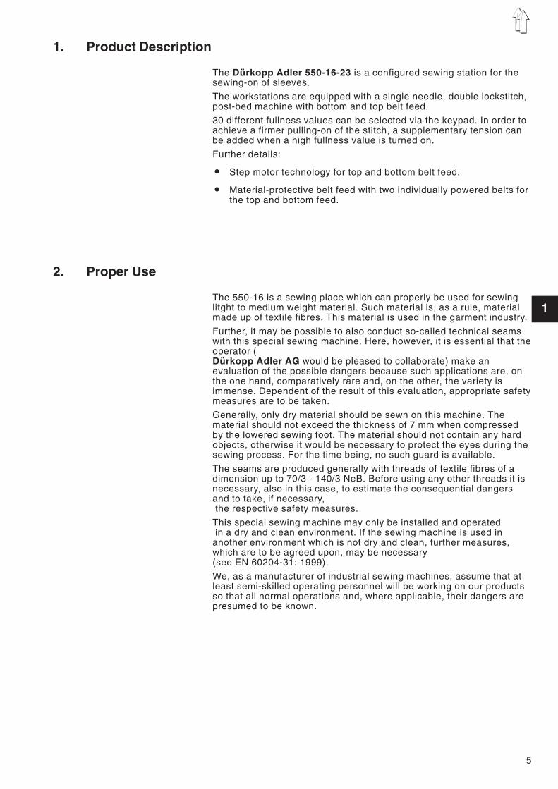
1. Product Description
The Dürkopp Adler 550-16-23 is a configured sewing station for thesewing-on of sleeves.
The workstations are equipped with a single needle, double lockstitch,post-bed machine with bottom and top belt feed.
30 different fullness values can be selected via the keypad. In order toachieve a firmer pulling-on of the stitch, a supplementary tension canbe added when a high fullness value is turned on.
Further details:
• Step motor technology for top and bottom belt feed.
• Material-protective belt feed with two individually powered belts forthe top and bottom feed.
2. Proper Use
The 550-16 is a sewing place which can properly be used for sewinglitght to medium weight material. Such material is, as a rule, materialmade up of textile fibres. This material is used in the garment industry.
Further, it may be possible to also conduct so-called technical seamswith this special sewing machine. Here, however, it is essential that theoperator (Dürkopp Adler AG would be pleased to collaborate) make anevaluation of the possible dangers because such applications are, onthe one hand, comparatively rare and, on the other, the variety isimmense. Dependent of the result of this evaluation, appropriate safetymeasures are to be taken.
Generally, only dry material should be sewn on this machine. Thematerial should not exceed the thickness of 7 mm when compressedby the lowered sewing foot. The material should not contain any hardobjects, otherwise it would be necessary to protect the eyes during thesewing process. For the time being, no such guard is available.
The seams are produced generally with threads of textile fibres of adimension up to 70/3 - 140/3 NeB. Before using any other threads it isnecessary, also in this case, to estimate the consequential dangersand to take, if necessary,the respective safety measures.
This special sewing machine may only be installed and operatedin a dry and clean environment. If the sewing machine is used in
another environment which is not dry and clean, further measures,which are to be agreed upon, may be necessary(see EN 60204-31: 1999).
We, as a manufacturer of industrial sewing machines, assume that atleast semi-skilled operating personnel will be working on our productsso that all normal operations and, where applicable, their dangers arepresumed to be known.
5
1

3. Technical Data
Noise Workstation-specific emission value to DIN 45635-48-A-1-KL2
Cl. 550-16-23 Lc = 79 dB (A)Stitch length: 4,4 [mm]
Number ofstitches: 2.500 [min-1]
Material: G1 DIN 23328 2-plies
Stitch type Double lockstitch
Needle system: 134 - 35797Sy1955-1
Needle thickness (as per E-No.:) [Nm] 70 - 100
Thickness of sewing thread max.: [Nm] 50/3
Number of stitches max.: [min-1] 4000
Stitch length max.: [mm] 1,5 - 5,5
Max. clearance under the sewing feet:- Sewing [mm]- Lifted [mm]
Operating pressure: [bar] 6
Air consumption per work cycle: approx. [NL] 0,6
Nominal voltage: 190-240V 50/60 Hz
Dimensions(L x B xH) [mm] 140 x 750 x 1300
Working level (ex works): [mm] 790
Weight [kg] 140
6
4. Operation
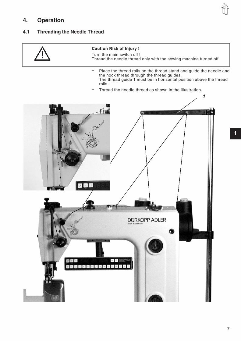
4.1 Threading the Needle Thread
Caution Risk of Injury !Turn the main switch off !Thread the needle thread only with the sewing machine turned off.
– Place the thread rolls on the thread stand and guide the needle andthe hook thread through the thread guides.The thread guide 1 must be in horizontal position above the threadrolls.
– Thread the needle thread as shown in the illustration.
7
1
1

Illus. A: Correct thread interlacingin the middle of the material
Illus. B: Needle thread tension too loworhook thread tension too highhigh
Illus. C: Needle thread tension toohighorhook thread tension too low
8
3 2 1 4

4.2 Setting the Needle Thread Tension
Pre-tensionWith open main tension 3 a slight residual tension on the needle threadis necessary. The residual tension is created by pre-tension 1.
The pre-tension 1 influences the length of the cut needle thread end atthe same time (starting thread for the next seam).– Base position:
Turn the knurled nut 1, until its face is flush with bolt 2.– Shorter starting thread:
Turn knurled nut 1 clockwise.
Main tensionThe main tension 3 is to be set as low as possible.
The interlacing of the threads should lie in the middle of the material.Too high thread tensions can lead to undesired puckering and threadbreakage in thin material.– Set the main tension 3 so that a uniform stitch formation is
achieved.Increase tension = Turn the knurled nut clockwise
Decrease tension = Turn the knurled nut -counterclockwise
ATTENTION !The main tension can be opened through the control.(e.g. for sewing Polsters)
Supplementary tensionThe supplementary tension 4 can be switched on for thicker gathering(programmable).– Set the supplementary tension 4 lower than the main tension 3.
4.3 Releasing the Needle Thread Tension
AutomaticThe needle thread tension is automatically opened during threadtrimming and lifting of the sewing foot.
9
1
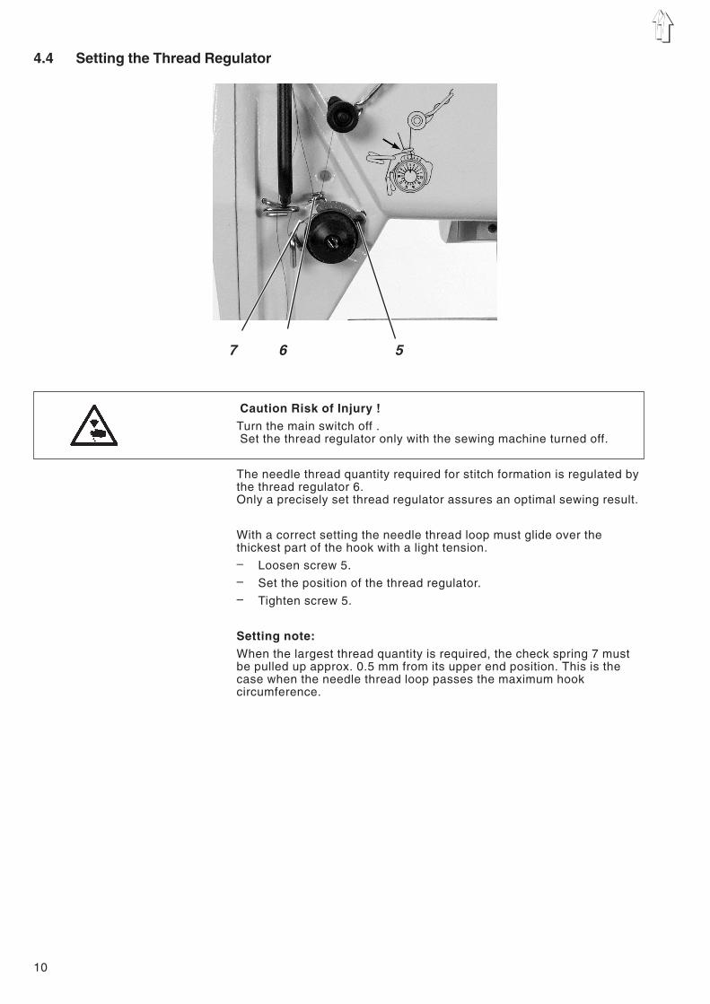
4.4 Setting the Thread Regulator
Caution Risk of Injury !Turn the main switch off .Set the thread regulator only with the sewing machine turned off.
The needle thread quantity required for stitch formation is regulated bythe thread regulator 6.Only a precisely set thread regulator assures an optimal sewing result.
With a correct setting the needle thread loop must glide over thethickest part of the hook with a light tension.– Loosen screw 5.– Set the position of the thread regulator.– Tighten screw 5.
Setting note:When the largest thread quantity is required, the check spring 7 mustbe pulled up approx. 0.5 mm from its upper end position. This is thecase when the needle thread loop passes the maximum hookcircumference.
10
7 6 5

4.5 Winding the Hook Thread
– Slip the bobbin onto the bobbin winder 2.– Pull the thread through the guide 3 and the tension 4.– Wind the thread clockwise about 5 times around the bobbin core
and tear off at the thread clamp.– Swing the bobbin winder lever 1 towards the bobbin .– Sewing
The bobbin winder lever will stop the winding process as soon asthe bobbin is full.
ATTENTION !If the thread is not to be wound during sewing,it is essential to arrest the sewing foot in the raised position.
(See chapter 4.10)
11
1
3 2 1

4.6 Changing the Hook Thread Bobbin
Caution Risk of Injury !Turn the main switch off .Change the hook thread bobbin only with the machine turned off.
Removing the empty bobbin– Swing the hook cover 2 down.– Bring the needle bar in high position.– Lift the bobbin case flap 1.– Take out the bobbin case top 3 with the bobbin 7.– Remove the empty bobbin from the bobbin case top 3.
Inserting a full bobbin– Insert the full bobbin in the bobbin case top 3.– Pull the hook thread through slit 6 under the tension spring 5 until
in the drilled hole 4.– Pull the hook thread approx. 5 cm out of the bobbin case 3.
The bobbin must turn in the direction of the arrow when the threadis pulled off.
– Insert the bobbin case 3 again.– Close the bobbin case flap 2.– Push the hook cover 2 upward.
12
3
65
4
17
2 1
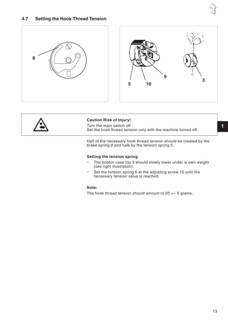
4.7 Setting the Hook Thread Tension
Caution Risk of Injury!Turn the main switch off .Set the hook thread tension only with the machine turned off.
Half of the necessary hook thread tension should be created by thebrake spring 8 and halb by the tension spring 5.
Setting the tension spring– The bobbin case top 3 should slowly lower under is own weight
(see right illustration).– Set the tension spring 5 at the adjusting screw 10 until the
necessary tension value is reached.
Note:The hook thread tension should amount to 20 +/- 5 grams.
13
1
39
105
8

4.8 Changing the Needle
Caution Risk of Injury!Turn the main switch off .Change the needle only with the sewing machine turned off.
– Loosen screw 1.– Push the new needle into the drilled hole of the needle bar 3 up to
the stop.ATTENTION !The furrow 2 of the needle must show to the hook point.
– Tighten screw 1.
ATTENTION !After a change to another needle thickness the clearance of the hookto the needle must be corrected (see Service Instructions).
The non-observance of the above correction can lead to followingfaults:– Change to a thinner needle: - Missing stitches
- Damage to the thread– Change to a thicker needle:
- Damage to the hook point- Damage to the needle
14
3
1
2

4.9 Sewing Foot Lift
The sewing foot can be lifted pneumatically by operating the pedal 4.
Pneumatic sewing foot lift (pedal)– Step half back on the pedal.
Lift the sewing feet.– Step completely back on the pedal.
Activate the thread trimmer and lift the sewing feet.
15
1
4
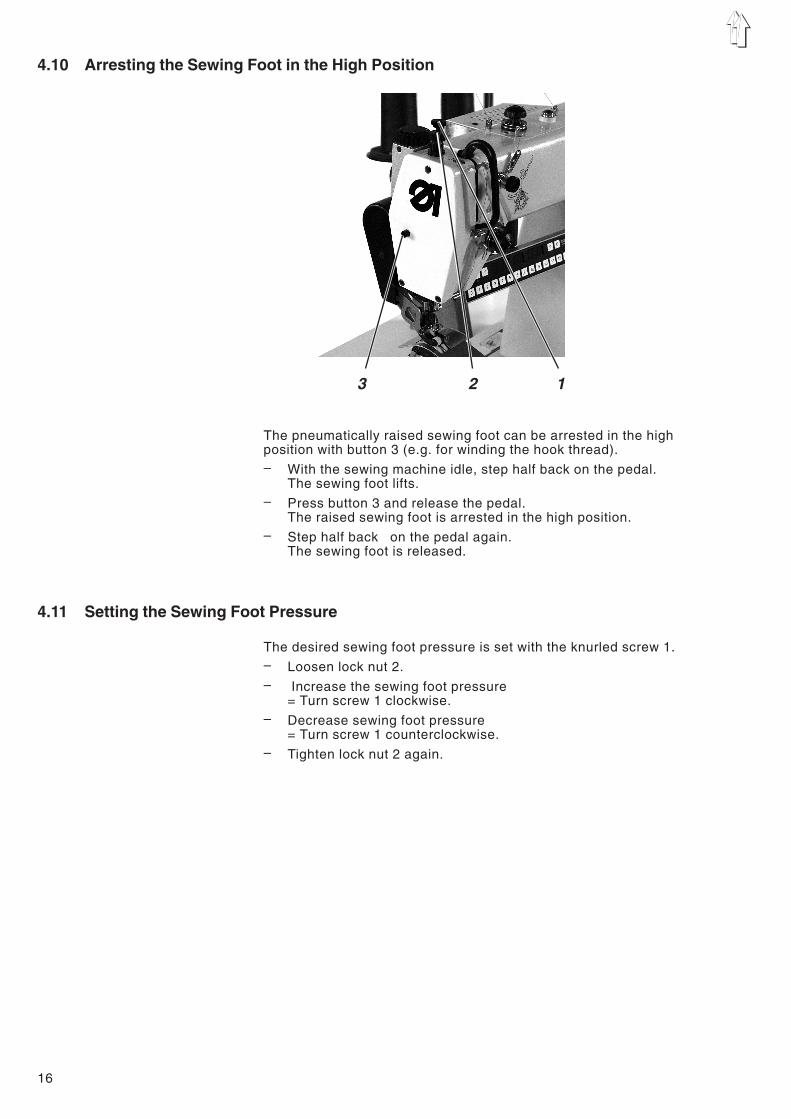
4.10 Arresting the Sewing Foot in the High Position
The pneumatically raised sewing foot can be arrested in the highposition with button 3 (e.g. for winding the hook thread).– With the sewing machine idle, step half back on the pedal.
The sewing foot lifts.– Press button 3 and release the pedal.
The raised sewing foot is arrested in the high position.– Step half back on the pedal again.
The sewing foot is released.
4.11 Setting the Sewing Foot Pressure
The desired sewing foot pressure is set with the knurled screw 1.– Loosen lock nut 2.– Increase the sewing foot pressure
= Turn screw 1 clockwise.– Decrease sewing foot pressure
= Turn screw 1 counterclockwise.– Tighten lock nut 2 again.
16
3 2 1
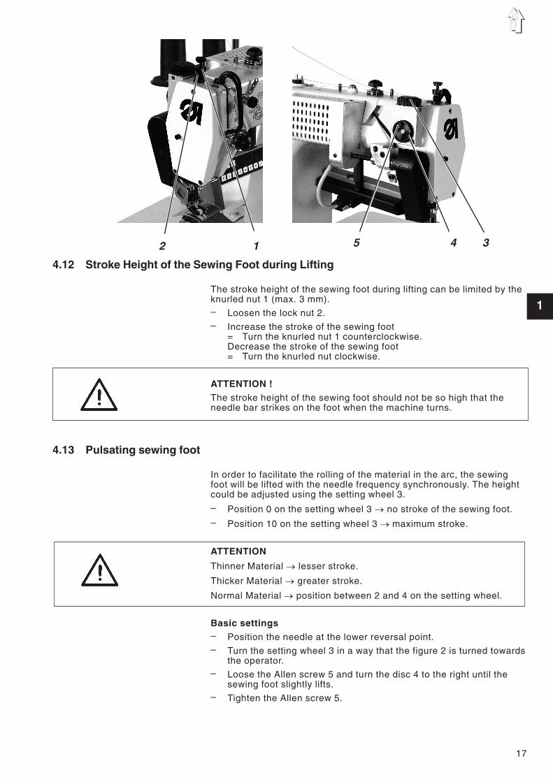
4.12 Stroke Height of the Sewing Foot during Lifting
The stroke height of the sewing foot during lifting can be limited by theknurled nut 1 (max. 3 mm).– Loosen the lock nut 2.– Increase the stroke of the sewing foot
= Turn the knurled nut 1 counterclockwise.Decrease the stroke of the sewing foot= Turn the knurled nut clockwise.
ATTENTION !The stroke height of the sewing foot should not be so high that theneedle bar strikes on the foot when the machine turns.
4.13 Pulsating sewing foot
In order to facilitate the rolling of the material in the arc, the sewingfoot will be lifted with the needle frequency synchronously. The heightcould be adjusted using the setting wheel 3.
– Position 0 on the setting wheel 3 � no stroke of the sewing foot.
– Position 10 on the setting wheel 3 � maximum stroke.
ATTENTION
Thinner Material � lesser stroke.
Thicker Material � greater stroke.
Normal Material � position between 2 and 4 on the setting wheel.
Basic settings– Position the needle at the lower reversal point.– Turn the setting wheel 3 in a way that the figure 2 is turned towards
the operator.– Loose the Allen screw 5 and turn the disc 4 to the right until the
sewing foot slightly lifts.– Tighten the Allen screw 5.
17
1
5 4 32 1
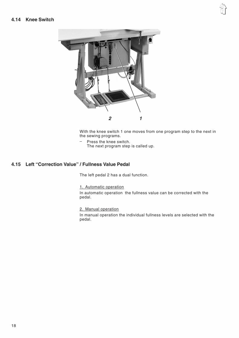
4.14 Knee Switch
With the knee switch 1 one moves from one program step to the next inthe sewing programs.– Press the knee switch.
The next program step is called up.
4.15 Left “Correction Value” / Fullness Value Pedal
The left pedal 2 has a dual function.
1. Automatic operation
In automatic operation the fullness value can be corrected with thepedal.
2. Manual operation
In manual operation the individual fullness levels are selected with thepedal.
18
2 1

5. Operating the Controls 550-16-23
The 550-16-23 is equipped with programmable controls. The functionscan be programmed via the keypad.
5.1 Manual Sewing
If sewing is to take place without a program, the manual sewing modeis to be activated using one of the following methods:– Press the “P” key.– Press the “0” key 2x.
Program “0" = manual is selected.– Select the fullness value with the 0 - 15 keys or the left pedal
(Setting-Global Parameters [13]).– Start the sewing cycle.
In manual operation the step and program numberdisplays are turned off.
5.1.1 Setting the Fullness Value
The desired fullness value is entered with the “1” to “15” keys. Anintermediate value (1/2) is set by pressing neighbouring fullness valuekeys simultaneously.
Setting a fullness value: (Example: Fullness value 5)– Press the “5” key.
5.1.2 Turning the Supplementary Thread Tension On/Off
The supplementary thread tension can be turned on at any time.– Press the “F” key.
The supplementary tension is turned on.The green LED under the key is lit.
– Press the “F” key again.The supplementary tension is turned off.The green LED goes out.
5.1.3 Turning the Thread Tension Off/On
By simultaneously pressing the “F” and “1” keys, the thread tensioncan be turned off and on again.– Hold down the “F” key and tap the “1” key.
The thread tension is turned off.– Hold down the “F” key and tap the “1” key again.
The thread tension is turned on.
19
1
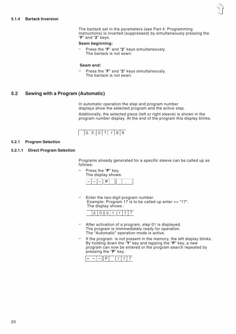
5.1.4 Bartack Inversion
The bartack set in the parameters (see Part 4: ProgrammingInstructions) is inverted (suppressed) by simultaneously pressing the“F” and “2” keys.
Seam beginning:– Press the “F” and “2” keys simultaneously.
The bartack is not sewn.
Seam end:– Press the “F” and “2” keys simultaneously.
The bartack is not sewn.
5.2 Sewing with a Program (Automatic)
In automatic operation the step and program numberdisplays show the selected program and the active step.
Additionally, the selected piece (left or right sleeve) is shown in theprogram number display. At the end of the program this display blinks.
5.2.1 Program Selection
5.2.1.1 Direct Program Selection
Programs already generated for a specific sleeve can be called up asfollows:– Press the “P” key.
The display shows:
– Enter the two-digit program number.Example: Program 17 is to be called up enter => “17".The display shows :
– After activation of a program, step 01 is displayed.The program is immmediately ready for operation.The “Automatic” operation mode is active.
– If the program is not present in the memory, the left display blinks.By holding down the “Y” key and tapping the “P” key, a newprogram can now be entered or the program search repeated bypressing the “P” key.
20

5.2.1.2 Program Selection via Menu
If the program number is unknown, all programs can be run throughsequentially in the following manner.
Order of operations– Press the “P” key.
Change-over to the “Program Selection” mode.– Press the “Y” key.
The first program is shown.Each pressing of the “Y” key moves to and shows the nextprogram.
If the program has valid data assigned to it, the following displayappears:
If the program has no valid data assigned to it, the followingappears:
– If the displayed program is to be selected,press the “E” key. (Example: Program 01)The following display appears.
5.2.1.3 Side Selection in a Program
After selection of a program one always goes first to the right piece (ifa right sleeve has been programmed).
In the automatic mode one can, however, alternate between “right” and“left” sleeves at any time.– Press the “E” key.
The controls switch to the left sleeve.The display shows:
– Press the “E” key again.The controls switch to the right sleeve again.The display shows:
21
1

5.2.2 Changing Fullness Values
For the adaption to differing types of material with the program step,the fullness values can be changed via the “0" to ”15" keys at any time.
Via the supplementary foot switch (see Chapter 6.16), the currentfullness value can be increased or decreased by 0.5.
Increasing or decreasing a fullness value by a whole value:Example: Set fullness value = 08– Press the “9" key.
The next higher fullness value is selected.– Press the “7" key.
The next lower fullness value is selected.
The changed fullness value is automatically deleted through selectionof the next program step.
Increasing or decreasing a fullness value by a half value:Example: Set fullness value = 08– Step forward on the foot pedal.
The fullness value is increased by 0.5.– Step back on the foot pedal.
The fullness value is decreased by 0.5.
The changed fullness value is automatically deleted through selectionof the next program step.
22

5.3 Programmable Functions
The machine settings described in the following are saved in memorywith each program.
5.3.1 Generating a New Program
The generation of a new program starts with the entry of a non-existentprogram number.– Press the “P” key.
– Enter a 2-digit program numberThe left display blinks.(If the left display does not blink the selected program alreadyexists.)
– Hold down the “Y” key and tap the “P” key.“01" appears in the middle display.The dots in the middle display blink.
The dots in the ”Step" and the “Sleeve Side” displays blink.
Note:One can alternate between left and right piece with the “E” key until thefirst fullness value/ special function has been selected (the sleeve sidedisplay no longer blinks).
– Enter a fullness value by pressing one of the keys from 0 to 15.If desired, activate supplementary functions for the step bypressing on one of the following keys :- F : Supplementary thread tension on / off- F + 1: Needle thread tension on/ off
– Press the knee switch.The next step is selected.The entered value is saved.The next value can be entered.
– This programming order can be continued up to step 13.– Press the “E” key.
The established values are mirrored for the second piece andsaved to memory.
or– Press the “Y” +"P“ keys.
The established values are saved only for the current piece andare not mirrored.
Note:During teaching, one can go back one step at a time with the “Y” key.
23
1

5.3.2 Temporary Changes in a Step
Every function in a step can be changed as required. This changeapplies only for this program run. When the step is exited thesechanges are lost. Parameter changes can also be made.
– Press the key for the desired fullness value.The new fullness value appears in the left display.When the program is run again the original value is activatedagain.
5.3.3 Saving Changes in the Program
If the program is to be changed permanently, proceed as follows :– Select the step to be altered.– Hold down the “Y” key and tap the “P” key.
The controls change to the editing mode.The decimal points in the step display blink.
ExampleEnter a new fullness value.– If desired, enter further parameters, such as e.g. supplementary
thread tension.– Hold down the “Y” key and tap the “P” key.
The complete program is saved.The program continues with the altered step.
Or– Press the “E” key.
The program is mirrored to the other sleeve side,
5.3.4 Deleting a Program
If an active program is to be deleted, this is possible with the followingkey entries :– Hold down the “Y” key and tap the “P” and “E” keys.– The keys must be held for 2 seconds, then the program number
goes out. After the release of all keys, the controls branch to theprogram number entry.
The program number display blinks.A new program number can be entered.
Note:The deleting of a program is only possible in a program which is notrunning.
24
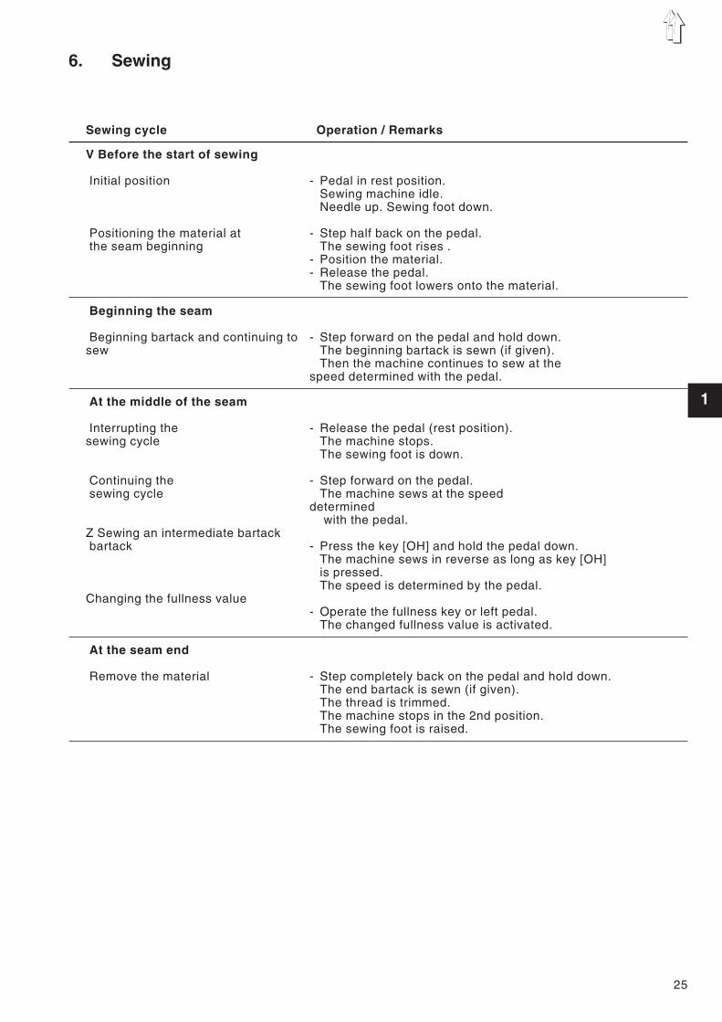
6. Sewing
Sewing cycle Operation / Remarks
V Before the start of sewing
Initial position
Positioning the material atthe seam beginning
- Pedal in rest position.Sewing machine idle.Needle up. Sewing foot down.
- Step half back on the pedal.The sewing foot rises .
- Position the material.- Release the pedal.
The sewing foot lowers onto the material.
Beginning the seam
Beginning bartack and continuing tosew
- Step forward on the pedal and hold down.The beginning bartack is sewn (if given).Then the machine continues to sew at the
speed determined with the pedal.
At the middle of the seam
Interrupting thesewing cycle
Continuing thesewing cycle
Z Sewing an intermediate bartackbartack
Changing the fullness value
- Release the pedal (rest position).The machine stops.The sewing foot is down.
- Step forward on the pedal.The machine sews at the speed
determinedwith the pedal.
- Press the key [OH] and hold the pedal down.The machine sews in reverse as long as key [OH]is pressed.The speed is determined by the pedal.
- Operate the fullness key or left pedal.The changed fullness value is activated.
At the seam end
Remove the material - Step completely back on the pedal and hold down.The end bartack is sewn (if given).The thread is trimmed.The machine stops in the 2nd position.The sewing foot is raised.
25
1
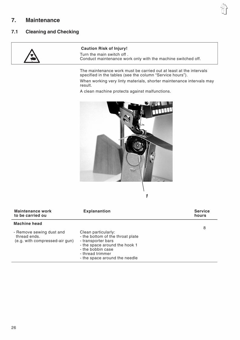
7. Maintenance
7.1 Cleaning and Checking
Caution Risk of Injury!Turn the main switch off .Conduct maintenance work only with the machine switched off.
The maintenance work must be carried out at least at the intervalsspecified in the tables (see the column “Service hours”).
When working very linty materials, shorter maintenance intervals mayresult.
A clean machine protects against malfunctions.
Maintenance work Explanantion Serviceto be carried ou hours
Machine head
- Remove sewing dust andthread ends.
(e.g. with compressed-air gun)
Clean particularly:- the bottom of the throat plate- transporter bars- the space around the hook 1- the bobbin case- thread trimmer- the space around the needle
8
26
1
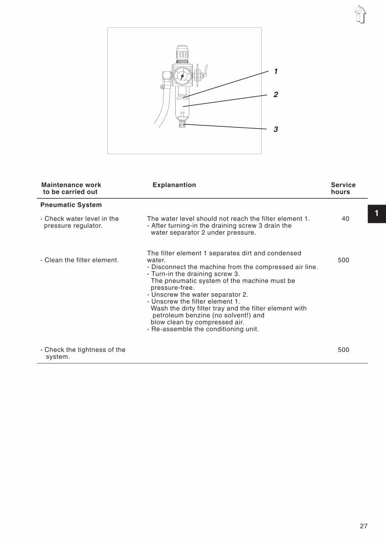
Maintenance work Explanantion Serviceto be carried out hours
Pneumatic System
- Check water level in thepressure regulator.
- Clean the filter element.
- Check the tightness of thesystem.
The water level should not reach the filter element 1.- After turning-in the draining screw 3 drain the
water separator 2 under pressure.
The filter element 1 separates dirt and condensedwater.- Disconnect the machine from the compressed air line.- Turn-in the draining screw 3.
The pneumatic system of the machine must bepressure-free.
- Unscrew the water separator 2.- Unscrew the filter element 1.
Wash the dirty filter tray and the filter element withpetroleum benzine (no solvent!) and
blow clean by compressed air.- Re-assemble the conditioning unit.
40
500
500
27
1
2
46
8
10
1
2
3

7.2 Lubrication
Caution Risk of Injury !Oil can cause skin rashes.Avoid longer skin contact.After contact wash yourself thoroughly.
ATTENTION !The handling and disposal of mineral oils is subject to legalregulations.Deliver used oil to an authorized reception point.Protect your environment.Take care not to spill any oil.
For lubrication of the special sewing machine, use exclusively thelubrication oil ESSO-SP-NK 10 or an equivalent oil with the followingspecification:– Viscosity at 40° C: 10 mm²/s– Flash point: 150° C
ESSO SP-NK 10 can be obtained from the sales offices ofDÜRKOPP ADLER AG under the following parts numbers:
2 liter container: 9047 000013
5 liter container: 9047 000014
Maintenance work Explanation Service-to be carried out hours
Lubrication of the machinehead
The lubrication of the machine head occurs via a centraloil wick system. Except for the hook all bearings arelubricated via the oil reservoir 1.
- The oil level should not drop below the mark “MIN”.
- Fill oil up to the “MAX” mark through the drilled holein the viewing glass.
40
28
1