Part 1 Networking Devices, Interconnecting Cisco 2-2: Connecting to the Internet L31 Visual...
262
Interconnecting Cisco Networking Devices, Part 1 Volume 1 Version 2.0 ICND1 Lab Guide Part Number: 97-3244-01
Transcript of Part 1 Networking Devices, Interconnecting Cisco 2-2: Connecting to the Internet L31 Visual...
Interconnecting CiscoNetworking Devices,Part 1Volume 1Version 2.0
ICND1
Lab GuidePart Number: 97-3244-01

Americas HeadquartersCisco Systems, Inc.San Jose, CA
Asia Pacific HeadquartersCisco Systems (USA) Pte. Ltd.Singapore
Europe HeadquartersCisco Systems International BVAmsterdam,The Netherlands
Cisco has more than 200 offices worldwide. Addresses, phone numbers, and fax numbers are listed on the Cisco Website atwww.cisco.com/go/offices.
Cisco and the Cisco logo are trademarks or registered trademarks of Cisco and/or its affiliates in the U.S. and other countries. Toview a list of Cisco trademarks, go to this URL: www.cisco.com/go/trademarks. Third party trademarks mentioned are the propertyof their respective owners. The use of the word partner does not imply a partnership relationship between Cisco and any othercompany. (1110R)
DISCLAIMER WARRANTY: THIS CONTENT IS BEING PROVIDED “AS IS.” CISCO MAKES AND YOU RECEIVE NOWARRANTIES IN CONNECTION WITH THE CONTENT PROVIDED HEREUNDER, EXPRESS, IMPLIED, STATUTORY OR INANY OTHER PROVISION OF THIS CONTENT OR COMMUNICATION BETWEEN CISCO AND YOU. CISCO SPECIFICALLYDISCLAIMS ALL IMPLIED WARRANTIES, INCLUDING WARRANTIES OF MERCHANTABILITY, NON-INFRINGEMENT ANDFITNESS FOR A PARTICULAR PURPOSE, OR ARISING FROM A COURSE OF DEALING, USAGE OR TRADE PRACTICE.This learning product may contain early release content, and while Cisco believes it to be accurate, it falls subject to thedisclaimer above.
© 2013 Cisco Systems, Inc.

Table of ContentsLab 1-1: Performing Switch Startup and Initial Configuration L1
Visual Objective L2Required Resources L3Command List L3Job Aids L4Task 1: Perform a Reload and Verify that the Switch Is Unconfigured L6Task 2: Configure the Switch with a Hostname and an IP Address L8Task 3: Explore Context-Sensitive Help L10Task 4: Improve the Usability of the CLI L11
Lab 1-2: Troubleshooting Switch Media Issues L13Visual Objective L14Required Resources L14Command List L15Job Aids L15Task 1: Lab Setup L16Task 2: Troubleshoot Connectivity Between Computer PC1 and Switch SW1 L17Task 3: Troubleshoot Connectivity Between Switch SW1 and the Branch Router L18
Lab 2-1: Performing Initial Router Setup and Configuration L19Visual Objective L20Required Resources L20Command List L21Job Aids L21Task 1: Inspect the Router Hardware and Software L23Task 2: Create the Initial Router Configuration L24Task 3: Improve the Usability of the CLI L26Task 4: Discover Connected Neighbors with Cisco Discovery Protocol L28
Lab 2-2: Connecting to the Internet L31Visual Objective L32Required Resources L32Command List L33Job Aids L33Task 1: Configure a Manual IP Address and Static Default Route L35Task 2: Configure a DHCP-Obtained IP Address L39Task 3: Configure NAT L42Task 4: Configure NAT with PAT L47
Lab 3-1: Enhancing the Security of the Initial Configuration L53Visual Objective L54Required Resources L54Command List L55Job Aids L56
Task 1: Add Password Protection L57Task 2: Enable SSH Remote Access L64Task 3: Limit Remote Access to Selected Network Addresses L69Task 4: Configure a Login Banner L71
Lab 3-2: Device Hardening L73Visual Objective L74Required Resources L74Command List L75Job Aids L75Task 1: Disable Unused Ports L77Task 2: Configure Port Security on a Switch L78Task 3: Disable Unused Services L81Task 4: Configure NTP L83
Lab 3-3: Filtering Traffic with ACLs L85Visual Objective L86Required Resources L86Command List L87Job Aids L87Task 1: Configure an ACL L88Task 2: Lab Setup L95Task 3: Troubleshoot an ACL L96
Lab 4-1: Configuring Expanded Switched Networks L111Visual Objective L112Required Resources L112Command List L113Job Aids L113Task 1: Configure a VLAN L115Task 2: Configure the Link Between Switches as a Trunk L120Task 3: Configure a Trunk Link on the Router L121
Lab 4-2: Configuring DHCP Server L125Visual Objective L126Required Resources L126Command List L126Job Aids L127Task 1: Configure DHCP Pools L129Task 2: Exclude Specific IP Addresses from DHCP Pools L133Task 3: Configure DHCP Relay Agent L134Task 4: Manually Assign IP Addresses L135
Lab 4-3: Implementing OSPF L139Visual Objective L140Required Resources L140Command List L141
ii Interconnecting Cisco Networking Devices, Part 1 © 2013 Cisco Systems, Inc.

Job Aids L141Task 1: Connect the Router to the WAN L143Task 2: Configure OSPF L144
Lab 5-1: Configure and Verify Basic IPv6 L147Visual Objective L148Required Resources L148Command List L149Job Aids L149Task 1: Enable IPv6 on the Router L150
Lab 5-2: Configure and Verify Stateless Autoconfiguration L153Visual Objective L154Required Resources L154Command List L155Job Aids L155Task 1: Enable Stateless Autoconfiguration on the Router L156
Lab 5-3: Configure and Verify IPv6 Routing L161Visual Objective L162Required Resources L162Command List L163Job Aids L163Task 1: Enable IPv6 Static Routing L164Task 2: Enable OSPFv3 L166
Lab S-1: ICND1 Superlab L169Visual Objective L170Required Resources L170Command List L170Job Aids L172Task 1: Configure Basic Settings, VLANs, Trunks, and Port Security on Switches L175Task 2: Configure Inter-VLAN Routing L180Task 3: Configure Internet Connectivity L190Task 4: Configure WAN Connectivity and a Dynamic Routing Protocol L196Task 5: Configure IPv6 Connectivity in the LAN L201Task 6: Configure the OSPFv3 Routing Protocol L208
Lab Answer Keys L217Lab 1-1: Performing Switch Startup and Initial Configuration L217Lab 1-2: Troubleshooting Switch Media Issues L224Lab 2-1: Performing Initial Router Setup and Configuration L227Lab 2-2: Connecting to the Internet L229Lab 3-1: Enhancing the Security of the Initial Configuration L232Lab 3-2: Device Hardening L235Lab 3-3: Filtering Traffic with ACLs L238Lab 4-1: Configuring Expanded Switched Networks L239
© 2013 Cisco Systems, Inc. Lab Guide iii
Lab 4-2: Configuring DHCP Server L242Lab 4-3: Implementing OSPF L244Lab 5-1: Configure and Verify Basic IPv6 L245Lab 5-2: Configure and Verify Stateless Autoconfiguration L245Lab 5-3: Configure and Verify IPv6 Routing L246Lab S-1: ICND1 Superlab L246
iv Interconnecting Cisco Networking Devices, Part 1 © 2013 Cisco Systems, Inc.

Lab 1-1: Performing SwitchStartup and InitialConfiguration
Activity OverviewObjectivesIn this activity, you will observe the switch boot procedure and perform basic switch configuration. Afteryou have completed this activity, you will be able to meet these objectives:
Restart the switch and verify the initial configuration messages
Complete the initial configuration of the Cisco Catalyst switch
Explore context-sensitive help
Improve the usability of the CLI
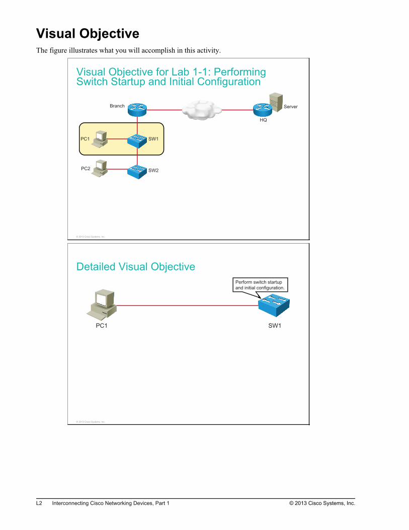
Visual ObjectiveThe figure illustrates what you will accomplish in this activity.
Visual Objective for Lab 1-1: PerformingSwitch Startup and Initial Configuration
Server
PC1
PC2
SW1
SW2
Branch
HQ
© 2013 Cisco Systems, Inc.
Detailed Visual ObjectivePerform switch startup
and initial configuration.
PC1 SW1
© 2013 Cisco Systems, Inc.
L2 Interconnecting Cisco Networking Devices, Part 1 © 2013 Cisco Systems, Inc.
Required ResourcesNo additional resources are required for this lab.
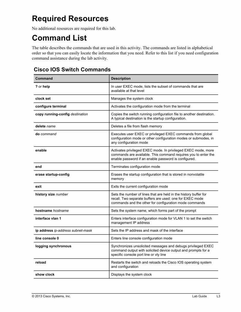
Command ListThe table describes the commands that are used in this activity. The commands are listed in alphabeticalorder so that you can easily locate the information that you need. Refer to this list if you need configurationcommand assistance during the lab activity.
Cisco IOS Switch CommandsCommand Description
? or help In user EXEC mode, lists the subset of commands that areavailable at that level
clock set Manages the system clock
configure terminal Activates the configuration mode from the terminal
copy running-config destination Copies the switch running configuration file to another destination.A typical destination is the startup configuration.
delete name Deletes a file from flash memory
do command Executes user EXEC or privileged EXEC commands from globalconfiguration mode or other configuration modes or submodes, inany configuration mode
enable Activates privileged EXEC mode. In privileged EXEC mode, morecommands are available. This command requires you to enter theenable password if an enable password is configured.
end Terminates configuration mode
erase startup-config Erases the startup configuration that is stored in nonvolatilememory
exit Exits the current configuration mode
history size number Sets the number of lines that are held in the history buffer forrecall. Two separate buffers are used: one for EXEC modecommands and the other for configuration mode commands
hostname hostname Sets the system name, which forms part of the prompt
interface vlan 1 Enters interface configuration mode for VLAN 1 to set the switchmanagement IP address
ip address ip-address subnet-mask Sets the IP address and mask of the interface
line console 0 Enters line console configuration mode
logging synchronous Synchronizes unsolicited messages and debugs privileged EXECcommand output with solicited device output and prompts for aspecific console port line or vty line
reload Restarts the switch and reloads the Cisco IOS operating systemand configuration
show clock Displays the system clock
© 2013 Cisco Systems, Inc. Lab Guide L3
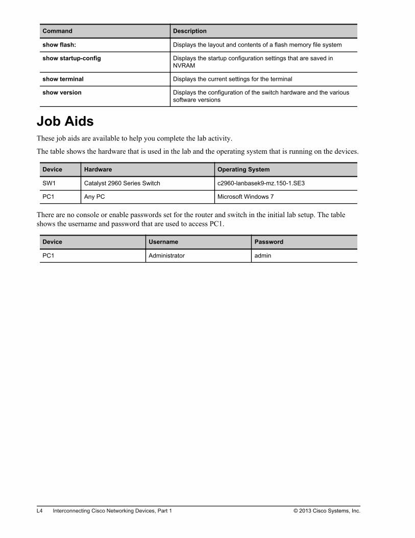
Command Description
show flash: Displays the layout and contents of a flash memory file system
show startup-config Displays the startup configuration settings that are saved inNVRAM
show terminal Displays the current settings for the terminal
show version Displays the configuration of the switch hardware and the varioussoftware versions
Job AidsThese job aids are available to help you complete the lab activity.
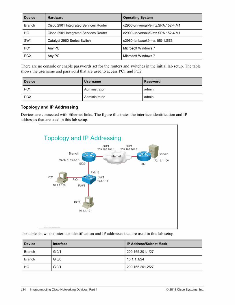
The table shows the hardware that is used in the lab and the operating system that is running on the devices.
Device Hardware Operating System
SW1 Catalyst 2960 Series Switch c2960-lanbasek9-mz.150-1.SE3
PC1 Any PC Microsoft Windows 7
There are no console or enable passwords set for the router and switch in the initial lab setup. The tableshows the username and password that are used to access PC1.
Device Username Password
PC1 Administrator admin
L4 Interconnecting Cisco Networking Devices, Part 1 © 2013 Cisco Systems, Inc.

Topology and IP Addressing
Devices are connected by Ethernet connections. The figure illustrates the interface identification and IPaddresses that are used in this lab setup.
Topology and IP Addressing
10.1.1.100 10.1.1.11
PC1 SW1
Fa0/1
© 2013 Cisco Systems, Inc.
The table shows the interface identification and IP addresses that are used in this lab setup.
Device Interface IP Address Subnet Mask
SW1 VLAN1 10.1.1.11 255.255.255.0
PC1 Ethernet adapter local areaconnection
10.1.1.100 255.255.255.0
© 2013 Cisco Systems, Inc. Lab Guide L5
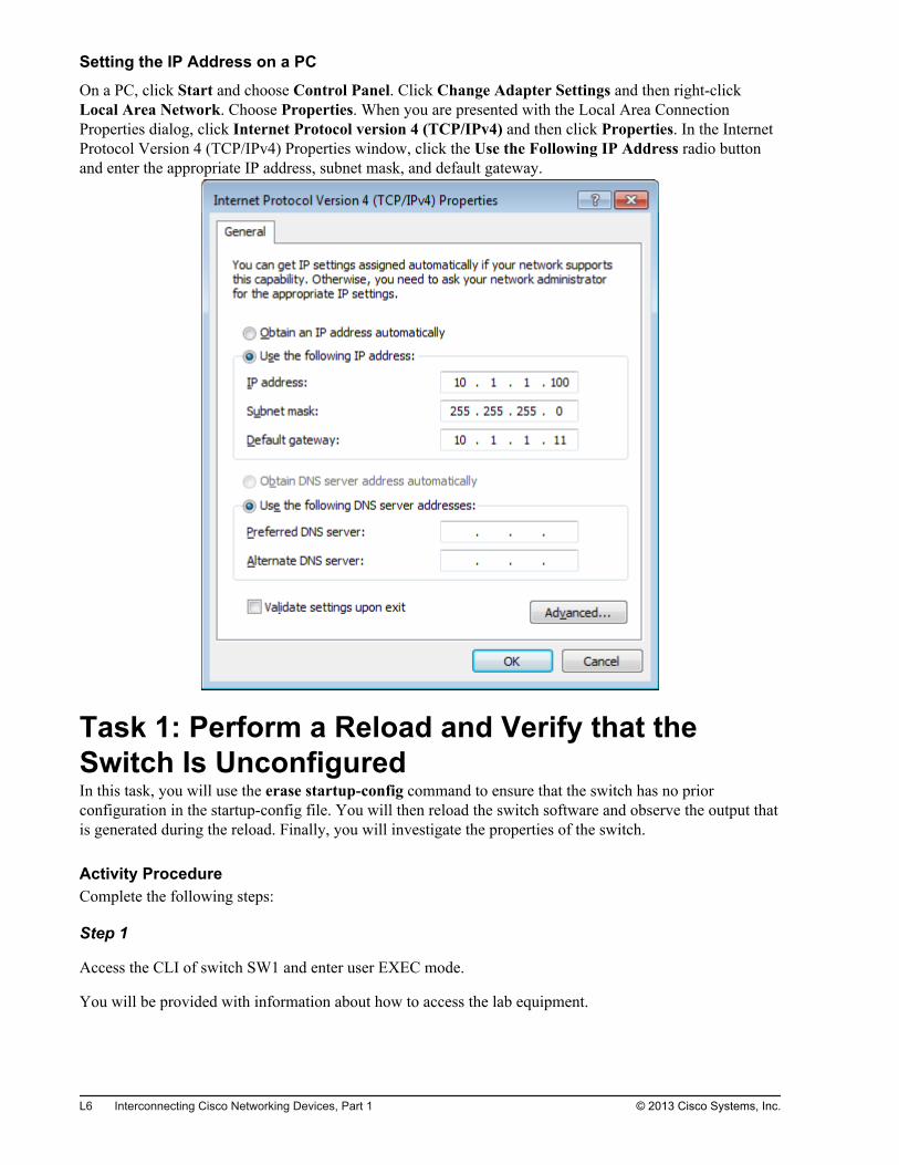
Setting the IP Address on a PC
On a PC, click Start and choose Control Panel. Click Change Adapter Settings and then right-clickLocal Area Network. Choose Properties. When you are presented with the Local Area ConnectionProperties dialog, click Internet Protocol version 4 (TCP/IPv4) and then click Properties. In the InternetProtocol Version 4 (TCP/IPv4) Properties window, click the Use the Following IP Address radio buttonand enter the appropriate IP address, subnet mask, and default gateway.
Task 1: Perform a Reload and Verify that theSwitch Is UnconfiguredIn this task, you will use the erase startup-config command to ensure that the switch has no priorconfiguration in the startup-config file. You will then reload the switch software and observe the output thatis generated during the reload. Finally, you will investigate the properties of the switch.
Activity ProcedureComplete the following steps:
Step 1
Access the CLI of switch SW1 and enter user EXEC mode.
You will be provided with information about how to access the lab equipment.
L6 Interconnecting Cisco Networking Devices, Part 1 © 2013 Cisco Systems, Inc.
Step 2
To see the effect of entering a privileged-level command in user EXEC mode, enter the command erasestartup-config.
What was the result of issuing the command in an incorrect EXEC mode?
Step 3
Enter privileged EXEC mode.
How do you know if you are in privileged EXEC mode and not user EXEC mode?
Step 4
Erase the startup configuration. Because the switch also stores a small part of the configuration in the file,vlan.dat, stored in flash memory, delete it before performing a reload. Observe the output during the reload.
Step 5
Press Enter when the switch boots and skip the initial configuration dialog. You will know when the switchhas finished booting when you see "Press RETURN to get started!" in the console output.
How do you know that the startup configuration has been erased?
Step 6
Using the appropriate show command, investigate the switch model number, software version, and amountof RAM and flash memory.
Activity VerificationYou have completed this task when you attain these results:
You performed a switch reload.
You verified that the switch is unconfigured.
© 2013 Cisco Systems, Inc. Lab Guide L7
Task 2: Configure the Switch with a Hostnameand an IP AddressIn this task, you will configure the switch with a hostname and an IP address.
Activity ProcedureComplete the following steps:
Step 1
Change the hostname of the switch to SW1.
Step 2
Assign an IP address to the VLAN 1 interface on switch SW1. Be sure that you assign the correct IPaddress, as described in the Job Aids section in the beginning of the lab document.
Note Configuring the IP address on the switch is not mandatory to start the switch running, but it is necessaryfor remote management access to the switch.
Step 3
Access the PC1. Use the username and password that is described in the Job Aids section in order to log in.
L8 Interconnecting Cisco Networking Devices, Part 1 © 2013 Cisco Systems, Inc.
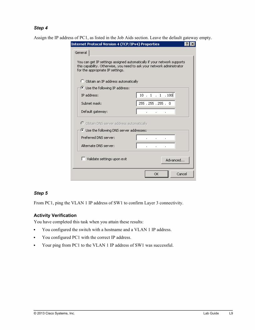
Step 4
Assign the IP address of PC1, as listed in the Job Aids section. Leave the default gateway empty.
Step 5
From PC1, ping the VLAN 1 IP address of SW1 to confirm Layer 3 connectivity.
Activity VerificationYou have completed this task when you attain these results:
You configured the switch with a hostname and a VLAN 1 IP address.
You configured PC1 with the correct IP address.
Your ping from PC1 to the VLAN 1 IP address of SW1 was successful.
© 2013 Cisco Systems, Inc. Lab Guide L9

Task 3: Explore Context-Sensitive HelpIn this task, you will use context-sensitive help to locate commands and complete command syntax.
Activity ProcedureComplete the following steps:
Step 1
On switch SW1, enter privileged EXEC mode and enter ? (or help) to list the available commands.
Step 2
Using the ? command, set the clock on the switch to the current time and date.
Note Pressing the Tab key automatically completes the command if the characters that you have entered arenot ambiguous.
Step 3
Verify the current date and time using the appropriate show command.
Step 4
Type the following comment line at the prompt and then press Enter:
!ths command changuw the clck sped for the swch
Note An exclamation point (!) at the beginning of the line indicates that you are entering a comment. Thecomment will not be part of the switch configuration. Comments are a great help when you are workingon a configuration in a text editor and plan to upload it to a device.
Step 5
Press Ctrl-P or press the Up Arrow key to see the previous line. Use the editor commands Ctrl-A, Ctrl-F,Ctrl-E, and Ctrl-B to move along the line, and use the Backspace key to delete unwanted characters.Using the editing commands, correct the comment line to read:
!This command changes the clock speed for the switch.
Activity VerificationYou have completed this task when you attain these results:
You used the system help and command-completion functions.
You used the built-in editor and the keystrokes for cursor navigation.
L10 Interconnecting Cisco Networking Devices, Part 1 © 2013 Cisco Systems, Inc.
Task 4: Improve the Usability of the CLIIn this task, you will enter commands to improve the usability of the CLI. You will increase the number oflines in the history buffer, increase the inactivity timer on the console port, and stop the attempted nameresolution of mistyped commands.
Activity ProcedureComplete the following steps:
Step 1
Using the show terminal command, verify that history is enabled, and determine the current history size forthe console line.
Step 2
Change the history size to 100 for the console line and verify that the change has taken place.
Note Alternatively, you could use the begin keyword. You will see the output beginning from the first match.
Step 3
The no ip domain lookup command disables the resolution of symbolic names. If you mistype a command,the system will not try to translate it into an IP address (it will take about 5 seconds to time out). Disable IPdomain lookup.
Step 4
The default console access EXEC timeout is set to 10 minutes. After 10 minutes of inactivity, the user isdisconnected from console access and is required to reconnect. Change this timer to 60 minutes.
Note Make sure that you are in console line configuration mode. To execute user EXEC or privileged EXECcommands from global configuration mode or other configuration modes or submodes, use the docommand in any configuration mode.
Step 5
The logging synchronous command synchronizes unsolicited messages and debugs privileged EXECcommand output with the input from the CLI. If you are in the middle of typing a command, statusmessages will appear where you are typing. Enable synchronous logging on line console 0.
Step 6
Save your running configuration to the startup configuration.
© 2013 Cisco Systems, Inc. Lab Guide L11

Activity VerificationYou have completed this task when you attain these results:
You changed the history buffer size.
You disabled resolution of symbolic names.
You set the inactivity timeout on the console line to 60 minutes.
You enabled synchronous logging on the console line.
You saved the running configuration to the startup configuration file.
L12 Interconnecting Cisco Networking Devices, Part 1 © 2013 Cisco Systems, Inc.
Lab 1-2: TroubleshootingSwitch Media Issues
Activity OverviewObjectivesIn this activity, you will use troubleshooting guidelines to isolate and correct switch media issues. Aftercompleting this activity, you will be able to meet these objectives:
Follow troubleshooting guidelines to determine the source of connectivity problems between acomputer and a switch, and fix them
Follow troubleshooting guidelines to determine the source of connectivity problems between a routerand a switch, and fix them
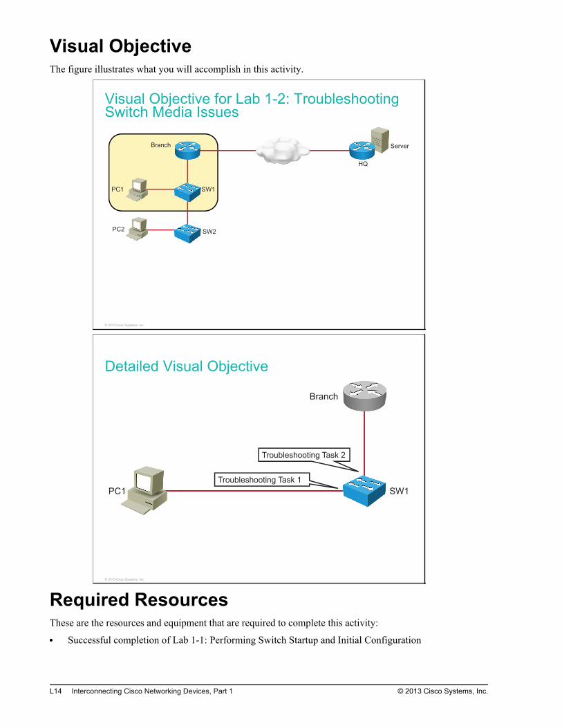
Visual ObjectiveThe figure illustrates what you will accomplish in this activity.
Visual Objective for Lab 1-2: TroubleshootingSwitch Media Issues
Server
PC1
PC2
SW1
SW2
Branch
HQ
© 2013 Cisco Systems, Inc.
Detailed Visual Objective
SW1PC1
Branch
Troubleshooting Task 1
Troubleshooting Task 2
© 2013 Cisco Systems, Inc.
Required ResourcesThese are the resources and equipment that are required to complete this activity:
Successful completion of Lab 1-1: Performing Switch Startup and Initial Configuration
L14 Interconnecting Cisco Networking Devices, Part 1 © 2013 Cisco Systems, Inc.
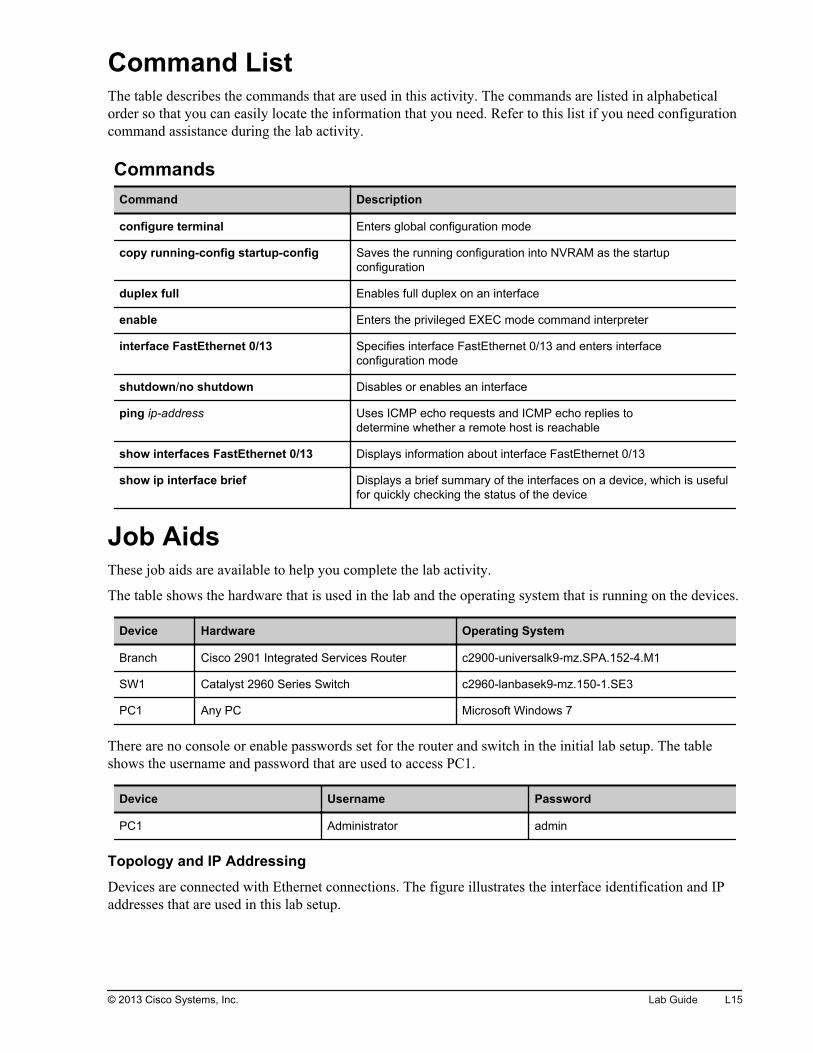
Command ListThe table describes the commands that are used in this activity. The commands are listed in alphabeticalorder so that you can easily locate the information that you need. Refer to this list if you need configurationcommand assistance during the lab activity.
CommandsCommand Description
configure terminal Enters global configuration mode
copy running-config startup-config Saves the running configuration into NVRAM as the startupconfiguration
duplex full Enables full duplex on an interface
enable Enters the privileged EXEC mode command interpreter
interface FastEthernet 0/13 Specifies interface FastEthernet 0/13 and enters interfaceconfiguration mode
shutdown/no shutdown Disables or enables an interface
ping ip-address Uses ICMP echo requests and ICMP echo replies todetermine whether a remote host is reachable
show interfaces FastEthernet 0/13 Displays information about interface FastEthernet 0/13
show ip interface brief Displays a brief summary of the interfaces on a device, which is usefulfor quickly checking the status of the device
Job AidsThese job aids are available to help you complete the lab activity.
The table shows the hardware that is used in the lab and the operating system that is running on the devices.
Device Hardware Operating System
Branch Cisco 2901 Integrated Services Router c2900-universalk9-mz.SPA.152-4.M1
SW1 Catalyst 2960 Series Switch c2960-lanbasek9-mz.150-1.SE3
PC1 Any PC Microsoft Windows 7
There are no console or enable passwords set for the router and switch in the initial lab setup. The tableshows the username and password that are used to access PC1.
Device Username Password
PC1 Administrator admin
Topology and IP Addressing
Devices are connected with Ethernet connections. The figure illustrates the interface identification and IPaddresses that are used in this lab setup.
© 2013 Cisco Systems, Inc. Lab Guide L15

Topology and IP Addressing
PC1 SW1
Fa0/1
10.1.1.100 10.1.1.11
Fa0/13
Gi0/010.1.1.1
© 2013 Cisco Systems, Inc.
The table shows the interface identification and IP addresses that are used in this lab setup.
Device Interface IP Address/Subnet Mask
Branch Gi0/0 10.1.1.1/24
SW1 VLAN1 10.1.1.11/24
PC1 Ethernet adapter local area connection 10.1.1.100/24
Task 1: Lab SetupIn this setup task, you will load the configuration from the switch flash drive.
Activity ProcedureComplete these steps:
Step 1
Access the CLI of switch SW1.
You will be provided with information about accessing the lab equipment.
L16 Interconnecting Cisco Networking Devices, Part 1 © 2013 Cisco Systems, Inc.
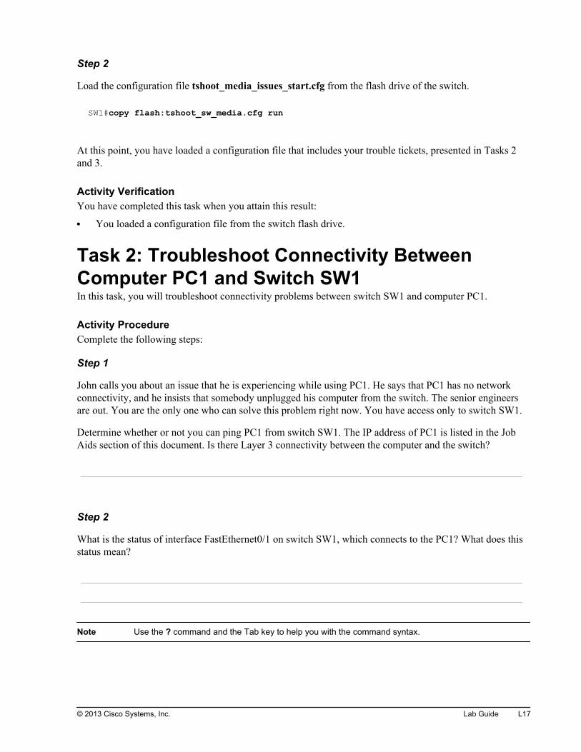
Step 2
Load the configuration file tshoot_media_issues_start.cfg from the flash drive of the switch.
SW1#copy flash:tshoot_sw_media.cfg run
At this point, you have loaded a configuration file that includes your trouble tickets, presented in Tasks 2and 3.
Activity VerificationYou have completed this task when you attain this result:
You loaded a configuration file from the switch flash drive.
Task 2: Troubleshoot Connectivity BetweenComputer PC1 and Switch SW1In this task, you will troubleshoot connectivity problems between switch SW1 and computer PC1.
Activity ProcedureComplete the following steps:
Step 1
John calls you about an issue that he is experiencing while using PC1. He says that PC1 has no networkconnectivity, and he insists that somebody unplugged his computer from the switch. The senior engineersare out. You are the only one who can solve this problem right now. You have access only to switch SW1.
Determine whether or not you can ping PC1 from switch SW1. The IP address of PC1 is listed in the JobAids section of this document. Is there Layer 3 connectivity between the computer and the switch?
Step 2
What is the status of interface FastEthernet0/1 on switch SW1, which connects to the PC1? What does thisstatus mean?
Note Use the ? command and the Tab key to help you with the command syntax.
© 2013 Cisco Systems, Inc. Lab Guide L17
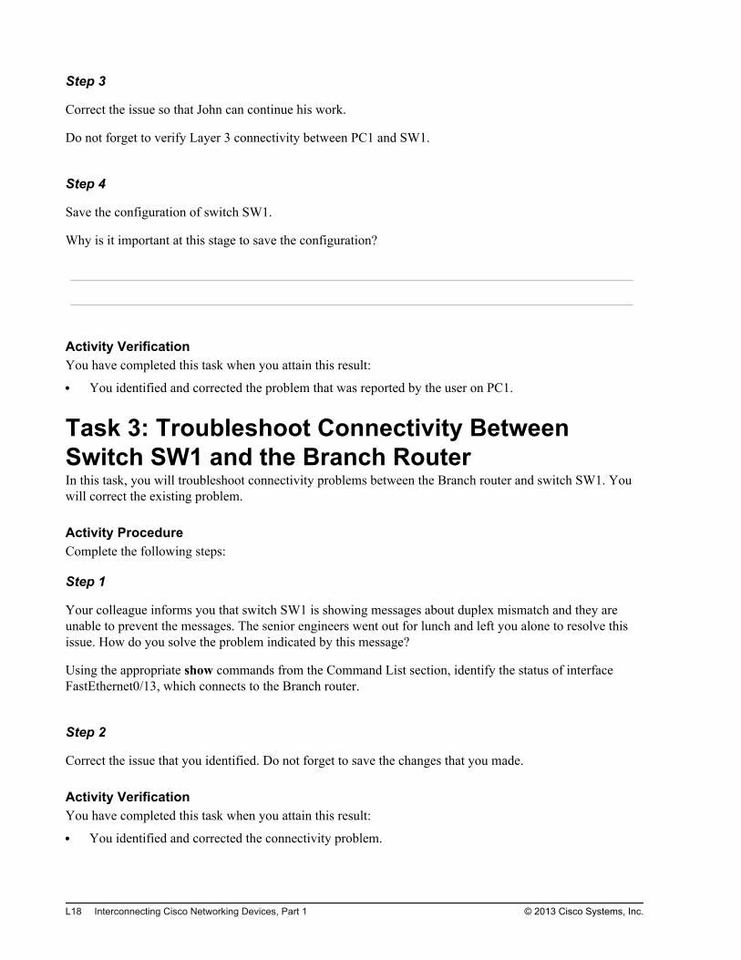
Step 3
Correct the issue so that John can continue his work.
Do not forget to verify Layer 3 connectivity between PC1 and SW1.
Step 4
Save the configuration of switch SW1.
Why is it important at this stage to save the configuration?
Activity VerificationYou have completed this task when you attain this result:
You identified and corrected the problem that was reported by the user on PC1.
Task 3: Troubleshoot Connectivity BetweenSwitch SW1 and the Branch RouterIn this task, you will troubleshoot connectivity problems between the Branch router and switch SW1. Youwill correct the existing problem.
Activity ProcedureComplete the following steps:
Step 1
Your colleague informs you that switch SW1 is showing messages about duplex mismatch and they areunable to prevent the messages. The senior engineers went out for lunch and left you alone to resolve thisissue. How do you solve the problem indicated by this message?
Using the appropriate show commands from the Command List section, identify the status of interfaceFastEthernet0/13, which connects to the Branch router.
Step 2
Correct the issue that you identified. Do not forget to save the changes that you made.
Activity VerificationYou have completed this task when you attain this result:
You identified and corrected the connectivity problem.
L18 Interconnecting Cisco Networking Devices, Part 1 © 2013 Cisco Systems, Inc.
Lab 2-1: Performing InitialRouter Setup andConfiguration
Activity OverviewObjectivesIn this activity, you will observe the router boot procedure and perform basic router configuration. Aftercompleting this activity, you will be able to meet these objectives:
Inspect router hardware and software
Perform initial router configuration
Improve the usability of the CLI
Use Cisco Discovery Protocol to discover how devices are interconnected
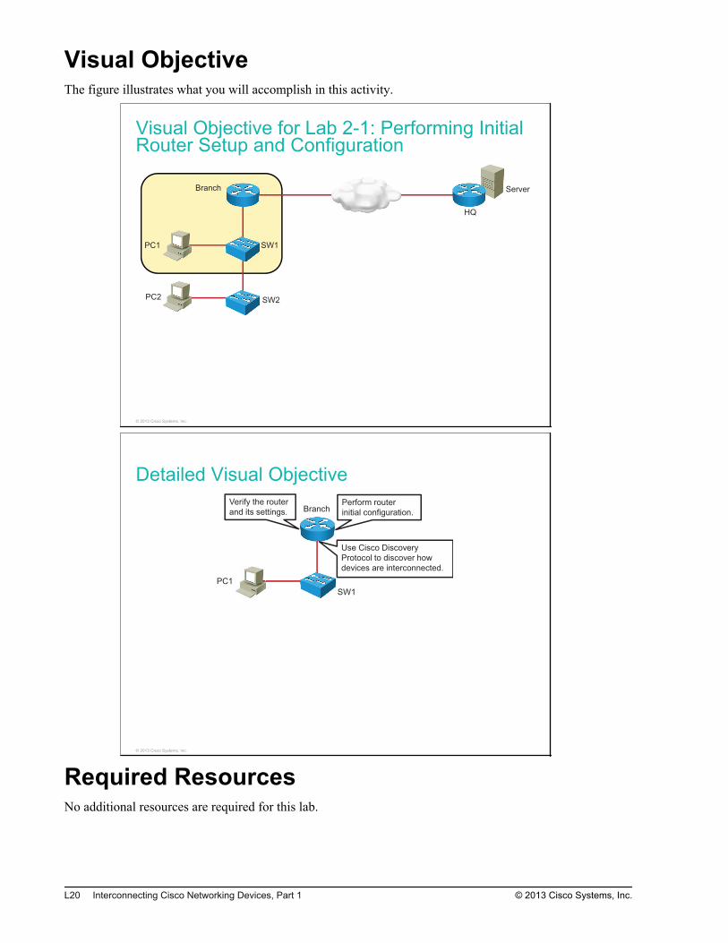
Visual ObjectiveThe figure illustrates what you will accomplish in this activity.
Visual Objective for Lab 2-1: Performing InitialRouter Setup and Configuration
Server
PC1
PC2
SW1
SW2
Branch
HQ
© 2013 Cisco Systems, Inc.
Detailed Visual Objective
PC1
SW1
BranchVerify the router
and its settings.Perform router
initial configuration.
Use Cisco Discovery
Protocol to discover how
devices are interconnected.
© 2013 Cisco Systems, Inc.
Required ResourcesNo additional resources are required for this lab.
L20 Interconnecting Cisco Networking Devices, Part 1 © 2013 Cisco Systems, Inc.

Command ListThe table describes the commands that are used in this activity. The commands are listed in alphabeticalorder so that you can easily locate the information that you need. Refer to this list if you need configurationcommand assistance during the lab activity.
Cisco IOS Router CommandsCommand Description
configure terminal Activates the configuration mode from the terminal.
copy running-config destination Copies the running configuration file to another destination. Atypical destination is the startup configuration.
description Adds a descriptive comment to the configuration of an interface.
enable Activates privileged EXEC mode. In privileged EXEC mode, morecommands are available.
erase startup-config Erases the startup configuration that is stored in nonvolatilememory.
exec-timeout Sets the interval before the user session is disconnected whenidle.
hostname hostname Sets the system name, which forms part of the prompt.
interface type module/slot/port Specifies an interface and enters interface configuration mode.
ip address ip-address subnet-mask Sets the IP address and mask of the interface.
[no] ip domain lookup Enables or disables DNS resolution of symbolic names.
line console 0 Enters line console configuration mode.
logging synchronous Synchronizes the display of router output messages with thecommand-line prompt.
ping ip_address Uses ICMP echo requests and ICMP echo replies to determinewhether a remote host is reachable.
reload Restarts the router and reloads the Cisco IOS operating system.
show cdp Displays global Cisco Discovery Protocol information.
show cdp neighbors [detail] Displays brief information about discovered neighboring Ciscodevices. If the keyword detail is used, detailed information aboutdiscovered devices is displayed.
show interfaces Displays information about all of the device interfaces.
show startup-config Displays the startup configuration settings that are saved innonvolatile memory.
show version Displays the configuration of the router hardware and thevarious software versions.
[no] shutdown Disables or enables an interface.
Job AidsThese job aids are available to help you complete the lab activity.
© 2013 Cisco Systems, Inc. Lab Guide L21
The table shows the hardware that is used in the lab and the operating system that is running on the devices.
Device Hardware Operating System
Branch Cisco 2901 Integrated Services Router c2900-universalk9-mz.SPA.152-4.M1
SW1 Catalyst 2960 Series Switch c2960-lanbasek9-mz.150-1.SE3
PC1 Any PC Microsoft Windows 7
There are no console or enable passwords set for the router and switch in the initial lab setup. The tableshows the username and password that are used to access PC1.
Device Username Password
PC1 Administrator admin
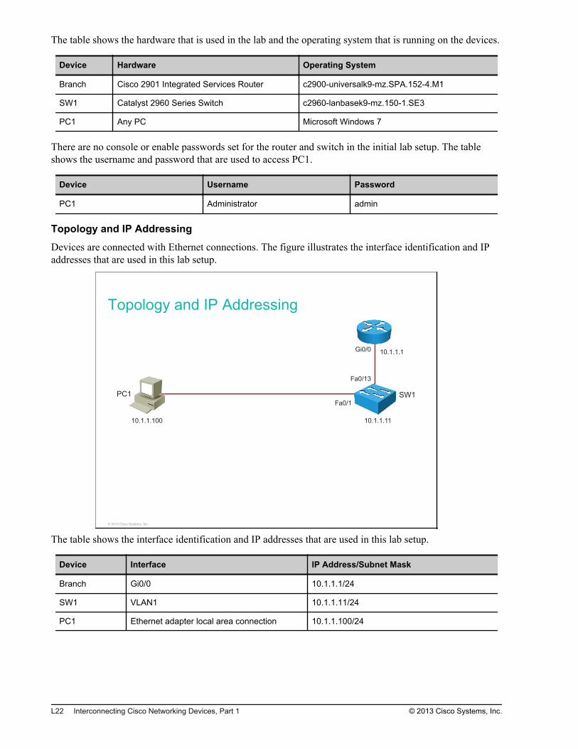
Topology and IP Addressing
Devices are connected with Ethernet connections. The figure illustrates the interface identification and IPaddresses that are used in this lab setup.
Topology and IP Addressing
PC1 SW1
Fa0/1
10.1.1.100 10.1.1.11
Fa0/13
Gi0/010.1.1.1
© 2013 Cisco Systems, Inc.
The table shows the interface identification and IP addresses that are used in this lab setup.
Device Interface IP Address/Subnet Mask
Branch Gi0/0 10.1.1.1/24
SW1 VLAN1 10.1.1.11/24
PC1 Ethernet adapter local area connection 10.1.1.100/24
L22 Interconnecting Cisco Networking Devices, Part 1 © 2013 Cisco Systems, Inc.
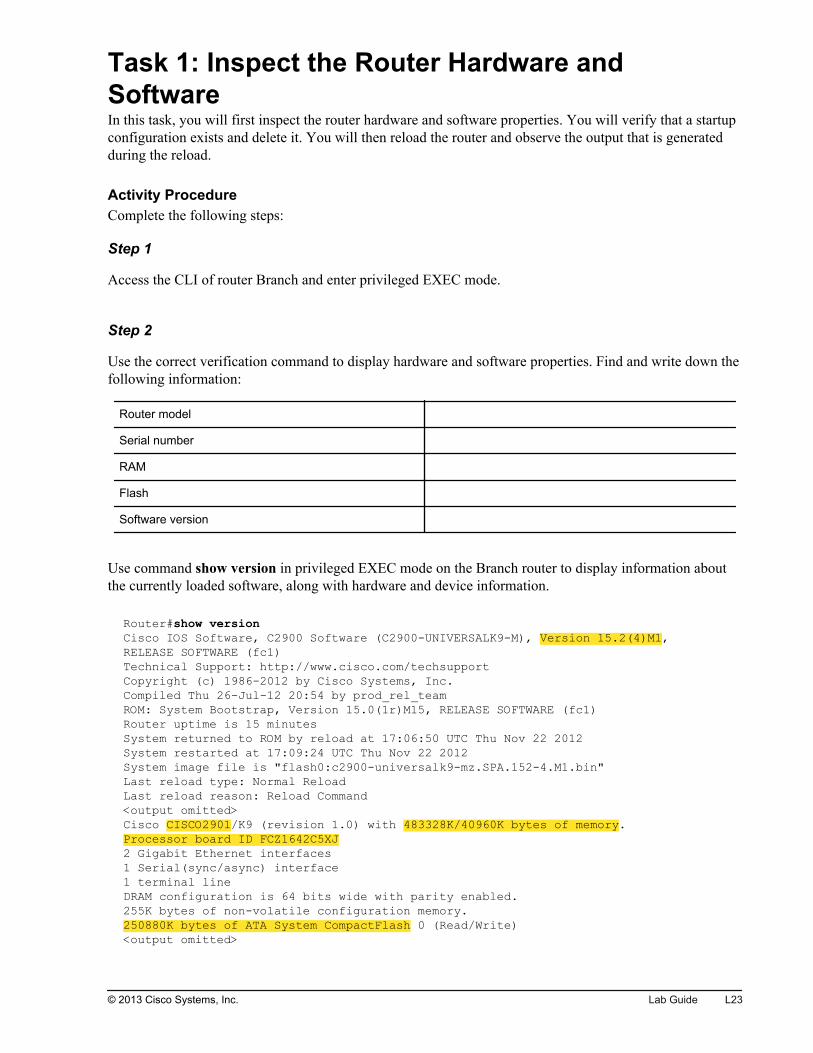
Task 1: Inspect the Router Hardware andSoftwareIn this task, you will first inspect the router hardware and software properties. You will verify that a startupconfiguration exists and delete it. You will then reload the router and observe the output that is generatedduring the reload.
Activity ProcedureComplete the following steps:
Step 1
Access the CLI of router Branch and enter privileged EXEC mode.
Step 2
Use the correct verification command to display hardware and software properties. Find and write down thefollowing information:
Router model
Serial number
RAM
Flash
Software version
Use command show version in privileged EXEC mode on the Branch router to display information aboutthe currently loaded software, along with hardware and device information.
Router#show versionCisco IOS Software, C2900 Software (C2900-UNIVERSALK9-M), Version 15.2(4)M1, RELEASE SOFTWARE (fc1)Technical Support: http://www.cisco.com/techsupportCopyright (c) 1986-2012 by Cisco Systems, Inc.Compiled Thu 26-Jul-12 20:54 by prod_rel_teamROM: System Bootstrap, Version 15.0(1r)M15, RELEASE SOFTWARE (fc1)Router uptime is 15 minutesSystem returned to ROM by reload at 17:06:50 UTC Thu Nov 22 2012System restarted at 17:09:24 UTC Thu Nov 22 2012System image file is "flash0:c2900-universalk9-mz.SPA.152-4.M1.bin"Last reload type: Normal ReloadLast reload reason: Reload Command<output omitted>Cisco CISCO2901/K9 (revision 1.0) with 483328K/40960K bytes of memory.Processor board ID FCZ1642C5XJ2 Gigabit Ethernet interfaces1 Serial(sync/async) interface1 terminal lineDRAM configuration is 64 bits wide with parity enabled.255K bytes of non-volatile configuration memory.250880K bytes of ATA System CompactFlash 0 (Read/Write)<output omitted>
© 2013 Cisco Systems, Inc. Lab Guide L23
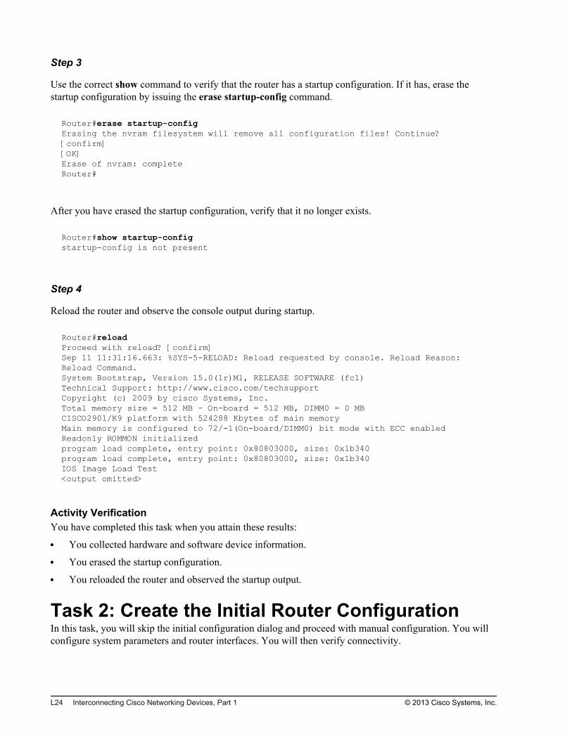
Step 3
Use the correct show command to verify that the router has a startup configuration. If it has, erase thestartup configuration by issuing the erase startup-config command.
Router#erase startup-configErasing the nvram filesystem will remove all configuration files! Continue? [confirm][OK]Erase of nvram: completeRouter#
After you have erased the startup configuration, verify that it no longer exists.
Router#show startup-configstartup-config is not present
Step 4
Reload the router and observe the console output during startup.
Router#reloadProceed with reload? [confirm]Sep 11 11:31:16.663: %SYS-5-RELOAD: Reload requested by console. Reload Reason: Reload Command.System Bootstrap, Version 15.0(1r)M1, RELEASE SOFTWARE (fc1)Technical Support: http://www.cisco.com/techsupportCopyright (c) 2009 by cisco Systems, Inc.Total memory size = 512 MB - On-board = 512 MB, DIMM0 = 0 MBCISCO2901/K9 platform with 524288 Kbytes of main memoryMain memory is configured to 72/-1(On-board/DIMM0) bit mode with ECC enabledReadonly ROMMON initializedprogram load complete, entry point: 0x80803000, size: 0x1b340program load complete, entry point: 0x80803000, size: 0x1b340IOS Image Load Test<output omitted>
Activity VerificationYou have completed this task when you attain these results:
You collected hardware and software device information.
You erased the startup configuration.
You reloaded the router and observed the startup output.
Task 2: Create the Initial Router ConfigurationIn this task, you will skip the initial configuration dialog and proceed with manual configuration. You willconfigure system parameters and router interfaces. You will then verify connectivity.
L24 Interconnecting Cisco Networking Devices, Part 1 © 2013 Cisco Systems, Inc.
Activity ProcedureComplete the following steps:
Step 1
Skip the initial configuration dialog, terminate the autoinstall, and enter privileged EXEC mode.
Step 2
Set the router host name to Branch. The prompt will reflect the new hostname.
Step 3
Enable interface GigabitEthernet0/0 and set its description to Link to LAN Switch.
Step 4
Configure the IP address 10.1.1.1 on the interface. Use subnet mask of 255.255.255.0.
Step 5
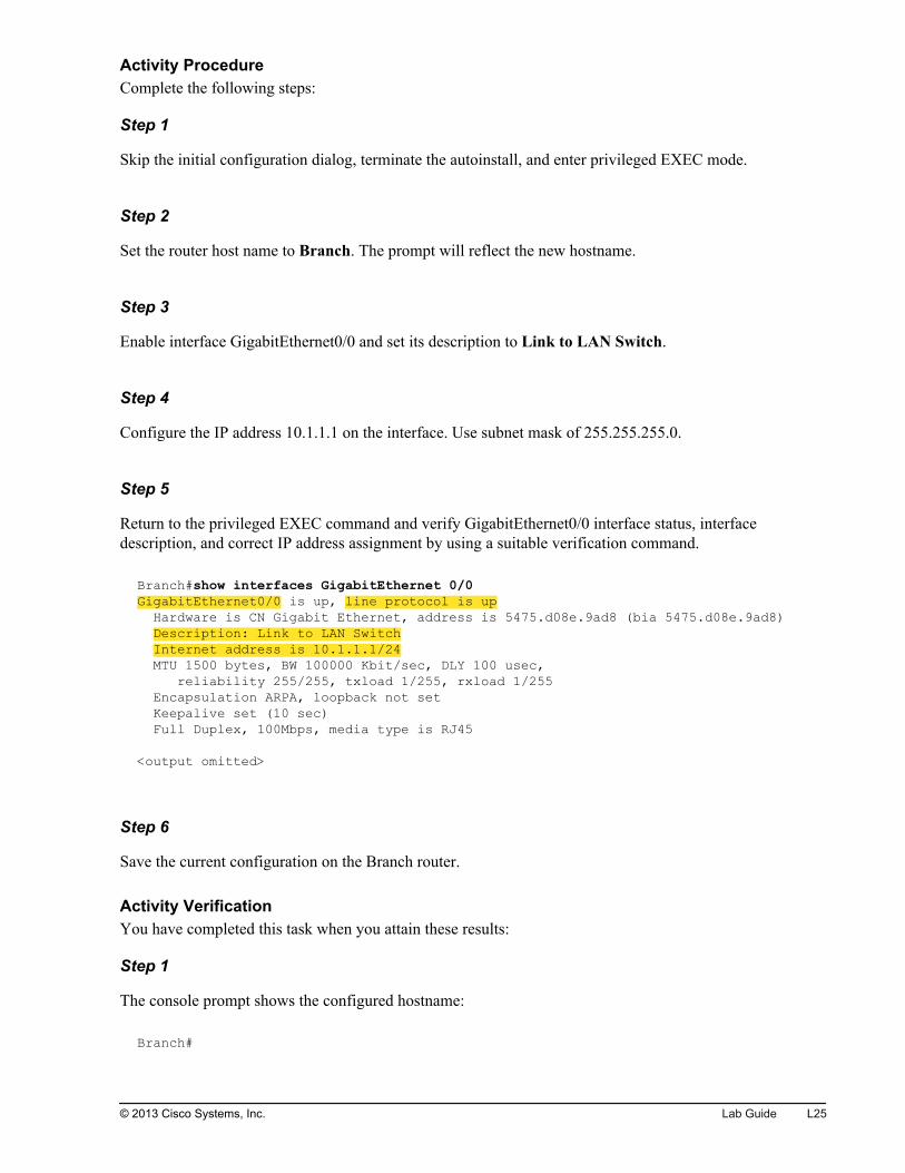
Return to the privileged EXEC command and verify GigabitEthernet0/0 interface status, interfacedescription, and correct IP address assignment by using a suitable verification command.
Branch#show interfaces GigabitEthernet 0/0GigabitEthernet0/0 is up, line protocol is up Hardware is CN Gigabit Ethernet, address is 5475.d08e.9ad8 (bia 5475.d08e.9ad8) Description: Link to LAN Switch Internet address is 10.1.1.1/24 MTU 1500 bytes, BW 100000 Kbit/sec, DLY 100 usec, reliability 255/255, txload 1/255, rxload 1/255 Encapsulation ARPA, loopback not set Keepalive set (10 sec) Full Duplex, 100Mbps, media type is RJ45 <output omitted>
Step 6
Save the current configuration on the Branch router.
Activity VerificationYou have completed this task when you attain these results:
Step 1
The console prompt shows the configured hostname:
Branch#
© 2013 Cisco Systems, Inc. Lab Guide L25
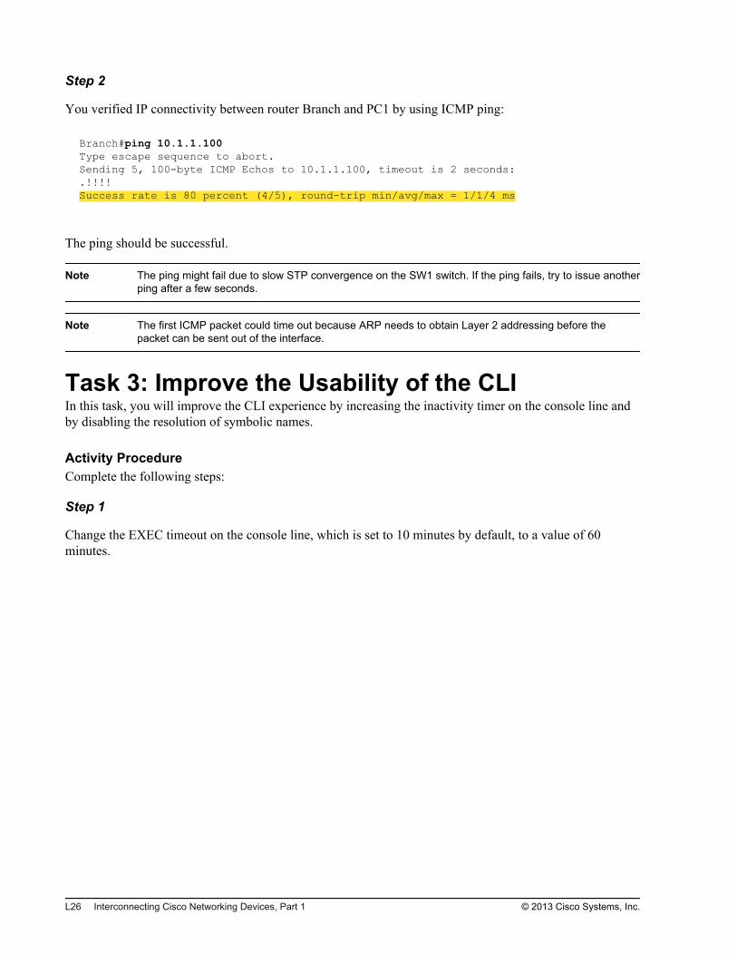
Step 2
You verified IP connectivity between router Branch and PC1 by using ICMP ping:
Branch#ping 10.1.1.100Type escape sequence to abort.Sending 5, 100-byte ICMP Echos to 10.1.1.100, timeout is 2 seconds:.!!!!Success rate is 80 percent (4/5), round-trip min/avg/max = 1/1/4 ms
The ping should be successful.
Note The ping might fail due to slow STP convergence on the SW1 switch. If the ping fails, try to issue anotherping after a few seconds.
Note The first ICMP packet could time out because ARP needs to obtain Layer 2 addressing before thepacket can be sent out of the interface.
Task 3: Improve the Usability of the CLIIn this task, you will improve the CLI experience by increasing the inactivity timer on the console line andby disabling the resolution of symbolic names.
Activity ProcedureComplete the following steps:
Step 1
Change the EXEC timeout on the console line, which is set to 10 minutes by default, to a value of 60minutes.
L26 Interconnecting Cisco Networking Devices, Part 1 © 2013 Cisco Systems, Inc.
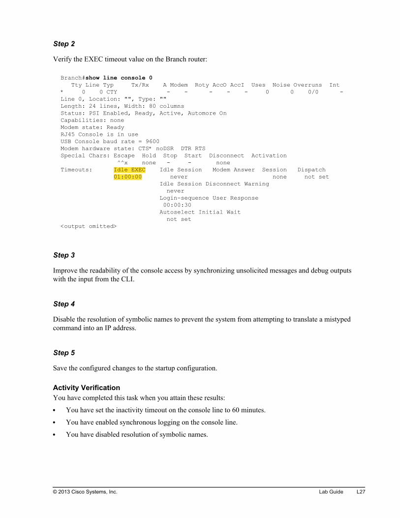
Step 2
Verify the EXEC timeout value on the Branch router:
Branch#show line console 0 Tty Line Typ Tx/Rx A Modem Roty AccO AccI Uses Noise Overruns Int* 0 0 CTY - - - - - 0 0 0/0 -Line 0, Location: "", Type: ""Length: 24 lines, Width: 80 columnsStatus: PSI Enabled, Ready, Active, Automore OnCapabilities: noneModem state: ReadyRJ45 Console is in useUSB Console baud rate = 9600Modem hardware state: CTS* noDSR DTR RTSSpecial Chars: Escape Hold Stop Start Disconnect Activation ^^x none - - noneTimeouts: Idle EXEC Idle Session Modem Answer Session Dispatch 01:00:00 never none not set Idle Session Disconnect Warning never Login-sequence User Response 00:00:30 Autoselect Initial Wait not set<output omitted>
Step 3
Improve the readability of the console access by synchronizing unsolicited messages and debug outputswith the input from the CLI.
Step 4
Disable the resolution of symbolic names to prevent the system from attempting to translate a mistypedcommand into an IP address.
Step 5
Save the configured changes to the startup configuration.
Activity VerificationYou have completed this task when you attain these results:
You have set the inactivity timeout on the console line to 60 minutes.
You have enabled synchronous logging on the console line.
You have disabled resolution of symbolic names.
© 2013 Cisco Systems, Inc. Lab Guide L27
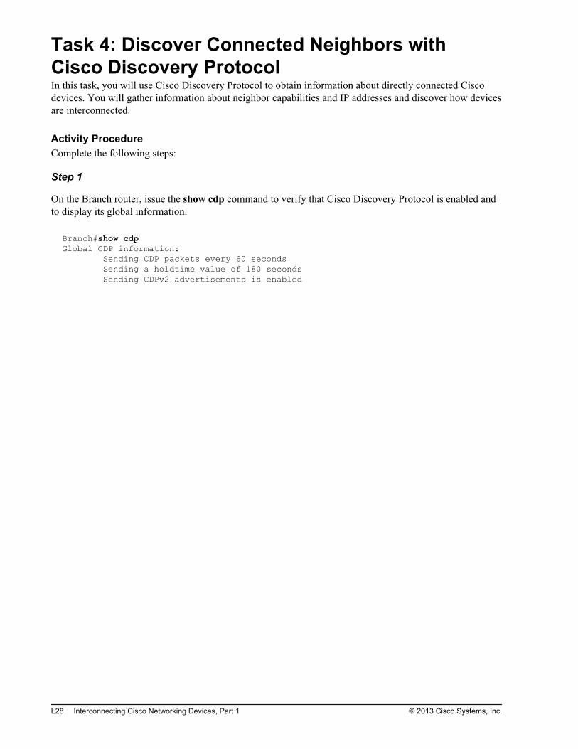
Task 4: Discover Connected Neighbors withCisco Discovery ProtocolIn this task, you will use Cisco Discovery Protocol to obtain information about directly connected Ciscodevices. You will gather information about neighbor capabilities and IP addresses and discover how devicesare interconnected.
Activity ProcedureComplete the following steps:
Step 1
On the Branch router, issue the show cdp command to verify that Cisco Discovery Protocol is enabled andto display its global information.
Branch#show cdpGlobal CDP information: Sending CDP packets every 60 seconds Sending a holdtime value of 180 seconds Sending CDPv2 advertisements is enabled
L28 Interconnecting Cisco Networking Devices, Part 1 © 2013 Cisco Systems, Inc.

Step 2
Enter the Cisco Discovery Protocol verification command to display all known neighboring Cisco devices.
Write down the information about the discovered neighbors in the table:
Device ID Platform Local Interface Remote Interface (PortID)
#
#
The information that you gather about the local and remote interfaces that are used reveals how neighboringdevices are physically interconnected.
On the Branch router, use the show cdp neighbors command to display all neighboring Cisco devices:
Branch#show cdp neighborsCapability Codes: R - Router, T - Trans Bridge, B - Source Route Bridge S - Switch, H - Host, I - IGMP, r - Repeater, P - Phone, D - Remote, C - CVTA, M - Two-port Mac RelayDevice ID Local Intrfce Holdtme Capability Platform Port IDSW1 Gig 0/0 158 S I WS-C2960- Fas 0/13
Use the Cisco Discovery Protocol verification command with the keyword detail to display additionalinformation about other Cisco devices. Write down the IP address of a neighboring switch, with exactinformation about its platform and software version.
Branch#show cdp neighbors detail-------------------------Device ID: SW1Entry address(es): IP address: 10.1.1.11Platform: cisco WS-C2960-24TT-L, Capabilities: Switch IGMPInterface: GigabitEthernet0/0, Port ID (outgoing port): FastEthernet0/13Holdtime : 146 secVersion :Cisco IOS Software, C2960 Software (C2960-LANBASEK9-M), Version 15.0(1)SE3, RELEASE SOFTWARE (fc1)Technical Support: http://www.cisco.com/techsupportCopyright (c) 1986-2012 by Cisco Systems, Inc.Compiled Wed 30-May-12 14:26 by prod_rel_teamadvertisement version: 2Protocol Hello: OUI=0x00000C, Protocol ID=0x0112; payload len=27, value=00000000FFFFFFFF010221FF000000000000001E147CBD00FF0000VTP Management Domain: 'rlab'Native VLAN: 1Duplex: fullBranch#
© 2013 Cisco Systems, Inc. Lab Guide L29

Activity VerificationYou have completed this task when you attain these results:
You observed Cisco Discovery Protocol output for directly attached Cisco neighbors.
You gathered detailed information about a neighbor switch.
L30 Interconnecting Cisco Networking Devices, Part 1 © 2013 Cisco Systems, Inc.
Lab 2-2: Connecting to theInternet
Activity OverviewObjectivesIn this activity, you will establish Internet connectivity by enabling static routing, DHCP, and NAT. Aftercompleting this activity, you will be able to meet these objectives:
Configure a static default route
Enable DHCP on a public interface
Configure NAT using a pool
Configure NAT with PAT
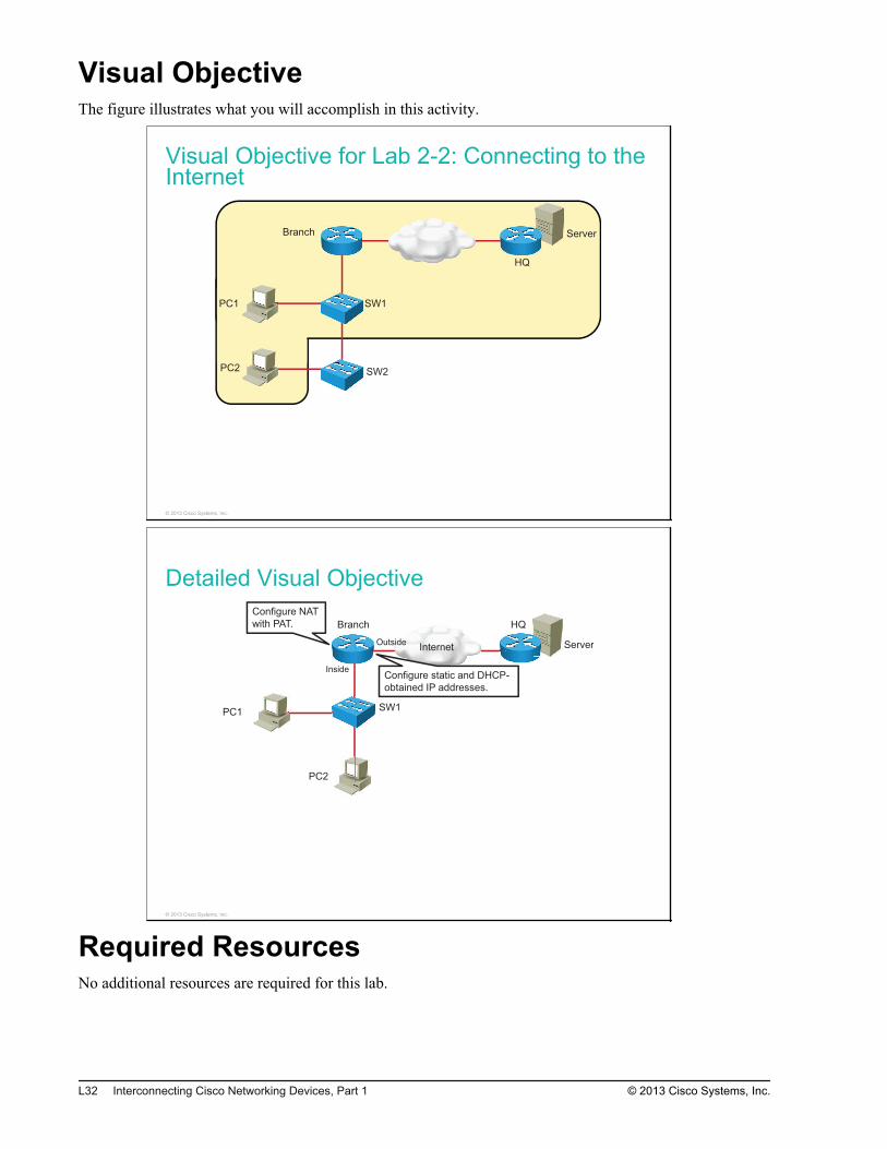
Visual ObjectiveThe figure illustrates what you will accomplish in this activity.
Visual Objective for Lab 2-2: Connecting to theInternet
Server
PC1
PC2
SW1
SW2
Branch
HQ
© 2013 Cisco Systems, Inc.
Detailed Visual Objective
Internet Server
PC1
PC2
SW1
Branch HQ
Configure NAT
with PAT.
Inside
Outside
Configure static and DHCP-
obtained IP addresses.
© 2013 Cisco Systems, Inc.
Required ResourcesNo additional resources are required for this lab.
L32 Interconnecting Cisco Networking Devices, Part 1 © 2013 Cisco Systems, Inc.
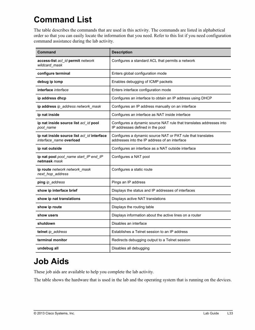
Command ListThe table describes the commands that are used in this activity. The commands are listed in alphabeticalorder so that you can easily locate the information that you need. Refer to this list if you need configurationcommand assistance during the lab activity.
Command Description
access-list acl_id permit networkwildcard_mask
Configures a standard ACL that permits a network
configure terminal Enters global configuration mode
debug ip icmp Enables debugging of ICMP packets
interface interface Enters interface configuration mode
ip address dhcp Configures an interface to obtain an IP address using DHCP
ip address ip_address network_mask Configures an IP address manually on an interface
ip nat inside Configures an interface as NAT inside interface
ip nat inside source list acl_id poolpool_name
Configures a dynamic source NAT rule that translates addresses intoIP addresses defined in the pool
ip nat inside source list acl_id interfaceinterface_name overload
Configures a dynamic source NAT or PAT rule that translatesaddresses into the IP address of an interface
ip nat outside Configures an interface as a NAT outside interface
ip nat pool pool_name start_IP end_IPnetmask mask
Configures a NAT pool
ip route network network_masknext_hop_address
Configures a static route
ping ip_address Pings an IP address
show ip interface brief Displays the status and IP addresses of interfaces
show ip nat translations Displays active NAT translations
show ip route Displays the routing table
show users Displays information about the active lines on a router
shutdown Disables an interface
telnet ip_address Establishes a Telnet session to an IP address
terminal monitor Redirects debugging output to a Telnet session
undebug all Disables all debugging
Job AidsThese job aids are available to help you complete the lab activity.
The table shows the hardware that is used in the lab and the operating system that is running on the devices.
© 2013 Cisco Systems, Inc. Lab Guide L33
Device Hardware Operating System
Branch Cisco 2901 Integrated Services Router c2900-universalk9-mz.SPA.152-4.M1
HQ Cisco 2901 Integrated Services Router c2900-universalk9-mz.SPA.152-4.M1
SW1 Catalyst 2960 Series Switch c2960-lanbasek9-mz.150-1.SE3
PC1 Any PC Microsoft Windows 7
PC2 Any PC Microsoft Windows 7
There are no console or enable passwords set for the routers and switches in the initial lab setup. The tableshows the username and password that are used to access PC1 and PC2.
Device Username Password
PC1 Administrator admin
PC2 Administrator admin
Topology and IP Addressing
Devices are connected with Ethernet links. The figure illustrates the interface identification and IPaddresses that are used in this lab setup.
Topology and IP Addressing
InternetServer
PC1
PC2
SW1
Branch
HQ
Fa0/1
Gi0/0
Fa0/13
Fa0/3
Gi0/1
209.165.201.1
Gi0/1
209.165.201.2
10.1.1.100
10.1.1.101
10.1.1.11
VLAN 1: 10.1.1.1 172.16.1.100
0/3
© 2013 Cisco Systems, Inc.
The table shows the interface identification and IP addresses that are used in this lab setup.
Device Interface IP Address/Subnet Mask
Branch Gi0/1 209.165.201.1/27
Branch Gi0/0 10.1.1.1/24
HQ Gi0/1 209.165.201.2/27
L34 Interconnecting Cisco Networking Devices, Part 1 © 2013 Cisco Systems, Inc.
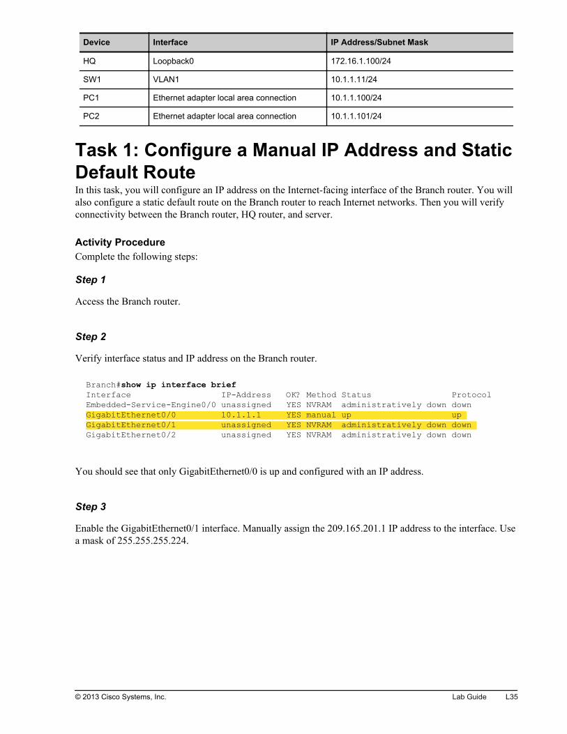
Device Interface IP Address/Subnet Mask
HQ Loopback0 172.16.1.100/24
SW1 VLAN1 10.1.1.11/24
PC1 Ethernet adapter local area connection 10.1.1.100/24
PC2 Ethernet adapter local area connection 10.1.1.101/24
Task 1: Configure a Manual IP Address and StaticDefault RouteIn this task, you will configure an IP address on the Internet-facing interface of the Branch router. You willalso configure a static default route on the Branch router to reach Internet networks. Then you will verifyconnectivity between the Branch router, HQ router, and server.
Activity ProcedureComplete the following steps:
Step 1
Access the Branch router.
Step 2
Verify interface status and IP address on the Branch router.
Branch#show ip interface brief Interface IP-Address OK? Method Status ProtocolEmbedded-Service-Engine0/0 unassigned YES NVRAM administratively down down GigabitEthernet0/0 10.1.1.1 YES manual up up GigabitEthernet0/1 unassigned YES NVRAM administratively down down GigabitEthernet0/2 unassigned YES NVRAM administratively down down
You should see that only GigabitEthernet0/0 is up and configured with an IP address.
Step 3
Enable the GigabitEthernet0/1 interface. Manually assign the 209.165.201.1 IP address to the interface. Usea mask of 255.255.255.224.
© 2013 Cisco Systems, Inc. Lab Guide L35
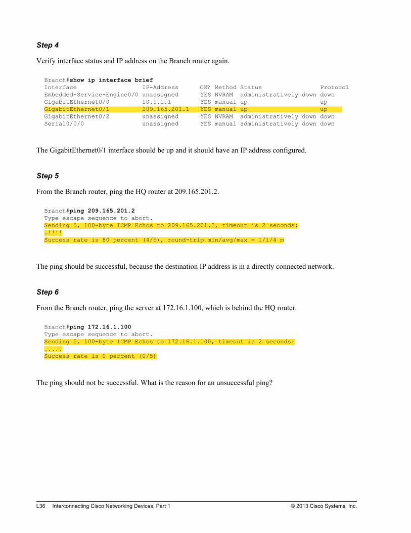
Step 4
Verify interface status and IP address on the Branch router again.
Branch#show ip interface brief Interface IP-Address OK? Method Status ProtocolEmbedded-Service-Engine0/0 unassigned YES NVRAM administratively down down GigabitEthernet0/0 10.1.1.1 YES manual up up GigabitEthernet0/1 209.165.201.1 YES manual up up GigabitEthernet0/2 unassigned YES NVRAM administratively down down Serial0/0/0 unassigned YES manual administratively down down
The GigabitEthernet0/1 interface should be up and it should have an IP address configured.
Step 5
From the Branch router, ping the HQ router at 209.165.201.2.
Branch#ping 209.165.201.2Type escape sequence to abort.Sending 5, 100-byte ICMP Echos to 209.165.201.2, timeout is 2 seconds:.!!!!Success rate is 80 percent (4/5), round-trip min/avg/max = 1/1/4 m
The ping should be successful, because the destination IP address is in a directly connected network.
Step 6
From the Branch router, ping the server at 172.16.1.100, which is behind the HQ router.
Branch#ping 172.16.1.100Type escape sequence to abort.Sending 5, 100-byte ICMP Echos to 172.16.1.100, timeout is 2 seconds:.....Success rate is 0 percent (0/5)
The ping should not be successful. What is the reason for an unsuccessful ping?
L36 Interconnecting Cisco Networking Devices, Part 1 © 2013 Cisco Systems, Inc.
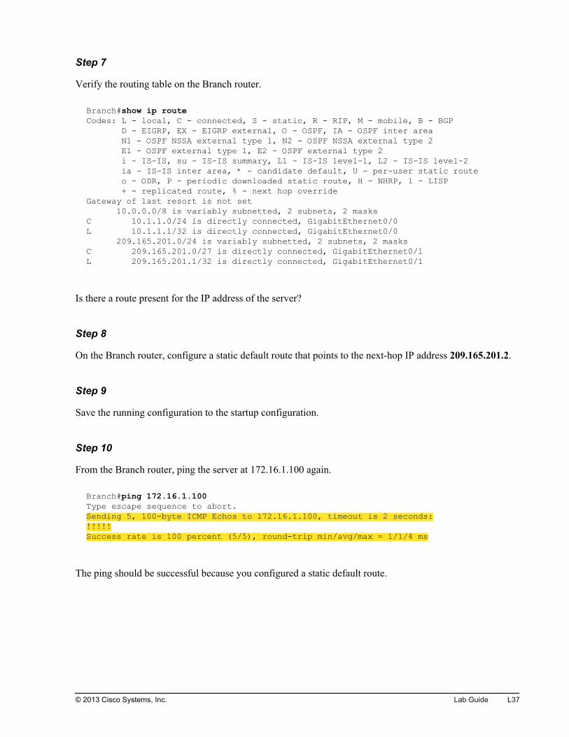
Step 7
Verify the routing table on the Branch router.
Branch#show ip route Codes: L - local, C - connected, S - static, R - RIP, M - mobile, B - BGP D - EIGRP, EX - EIGRP external, O - OSPF, IA - OSPF inter area N1 - OSPF NSSA external type 1, N2 - OSPF NSSA external type 2 E1 - OSPF external type 1, E2 - OSPF external type 2 i - IS-IS, su - IS-IS summary, L1 - IS-IS level-1, L2 - IS-IS level-2 ia - IS-IS inter area, * - candidate default, U - per-user static route o - ODR, P - periodic downloaded static route, H - NHRP, l - LISP + - replicated route, % - next hop overrideGateway of last resort is not set 10.0.0.0/8 is variably subnetted, 2 subnets, 2 masksC 10.1.1.0/24 is directly connected, GigabitEthernet0/0L 10.1.1.1/32 is directly connected, GigabitEthernet0/0 209.165.201.0/24 is variably subnetted, 2 subnets, 2 masksC 209.165.201.0/27 is directly connected, GigabitEthernet0/1L 209.165.201.1/32 is directly connected, GigabitEthernet0/1
Is there a route present for the IP address of the server?
Step 8
On the Branch router, configure a static default route that points to the next-hop IP address 209.165.201.2.
Step 9
Save the running configuration to the startup configuration.
Step 10
From the Branch router, ping the server at 172.16.1.100 again.
Branch#ping 172.16.1.100Type escape sequence to abort.Sending 5, 100-byte ICMP Echos to 172.16.1.100, timeout is 2 seconds:!!!!!Success rate is 100 percent (5/5), round-trip min/avg/max = 1/1/4 ms
The ping should be successful because you configured a static default route.
© 2013 Cisco Systems, Inc. Lab Guide L37

Step 11
Verify the routing table on the Branch router.
Branch#show ip route Codes: L - local, C - connected, S - static, R - RIP, M - mobile, B - BGP D - EIGRP, EX - EIGRP external, O - OSPF, IA - OSPF inter area N1 - OSPF NSSA external type 1, N2 - OSPF NSSA external type 2 E1 - OSPF external type 1, E2 - OSPF external type 2 i - IS-IS, su - IS-IS summary, L1 - IS-IS level-1, L2 - IS-IS level-2 ia - IS-IS inter area, * - candidate default, U - per-user static route o - ODR, P - periodic downloaded static route, H - NHRP, l - LISP + - replicated route, % - next hop overrideGateway of last resort is 209.165.201.2 to network 0.0.0.0S* 0.0.0.0/0 [1/0] via 209.165.201.2 10.0.0.0/8 is variably subnetted, 2 subnets, 2 masksC 10.1.1.0/24 is directly connected, GigabitEthernet0/0L 10.1.1.1/32 is directly connected, GigabitEthernet0/0 209.165.201.0/24 is variably subnetted, 2 subnets, 2 masksC 209.165.201.0/27 is directly connected, GigabitEthernet0/1L 209.165.201.1/32 is directly connected, GigabitEthernet0/1
The default route is designated with S and an asterisk (*).
Step 12
Remove the previously configured static default route from the Branch router to prepare the router for thenext task.
Step 13
Verify the routing table on the Branch router again to make sure that no default route is present on therouter.
Branch#show ip route Codes: L - local, C - connected, S - static, R - RIP, M - mobile, B - BGP D - EIGRP, EX - EIGRP external, O - OSPF, IA - OSPF inter area N1 - OSPF NSSA external type 1, N2 - OSPF NSSA external type 2 E1 - OSPF external type 1, E2 - OSPF external type 2 i - IS-IS, su - IS-IS summary, L1 - IS-IS level-1, L2 - IS-IS level-2 ia - IS-IS inter area, * - candidate default, U - per-user static route o - ODR, P - periodic downloaded static route, H - NHRP, l - LISP + - replicated route, % - next hop overrideGateway of last resort is not set 10.0.0.0/8 is variably subnetted, 2 subnets, 2 masksC 10.1.1.0/24 is directly connected, GigabitEthernet0/0L 10.1.1.1/32 is directly connected, GigabitEthernet0/0 209.165.201.0/24 is variably subnetted, 2 subnets, 2 masksC 209.165.201.0/27 is directly connected, GigabitEthernet0/1L 209.165.201.1/32 is directly connected, GigabitEthernet0/1
L38 Interconnecting Cisco Networking Devices, Part 1 © 2013 Cisco Systems, Inc.
Activity VerificationNo additional verification is needed in this task.
Task 2: Configure a DHCP-Obtained IP AddressIn this task, you will configure the Branch router to obtain an IP address using DHCP from the HQ router.The HQ router has been preconfigured as a DHCP server. You will also verify connectivity between theBranch router, HQ router, and server.
Activity ProcedureComplete the following steps:
Step 1
Access the Branch router.
Step 2
Configure the GigabitEthernet0/1 interface to obtain an IP address using DHCP.
Step 3
Save the running configuration to the startup configuration.
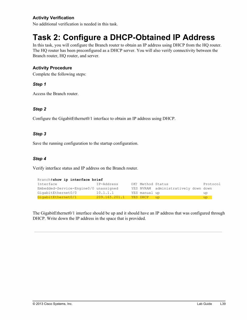
Step 4
Verify interface status and IP address on the Branch router.
Branch#show ip interface brief Interface IP-Address OK? Method Status ProtocolEmbedded-Service-Engine0/0 unassigned YES NVRAM administratively down down GigabitEthernet0/0 10.1.1.1 YES manual up up GigabitEthernet0/1 209.165.201.1 YES DHCP up up
The GigabitEthernet0/1 interface should be up and it should have an IP address that was configured throughDHCP. Write down the IP address in the space that is provided.
© 2013 Cisco Systems, Inc. Lab Guide L39

Step 5
Verify the routing table on the Branch router.
Branch#show ip routeCodes: L - local, C - connected, S - static, R - RIP, M - mobile, B - BGP D - EIGRP, EX - EIGRP external, O - OSPF, IA - OSPF inter area N1 - OSPF NSSA external type 1, N2 - OSPF NSSA external type 2 E1 - OSPF external type 1, E2 - OSPF external type 2 i - IS-IS, su - IS-IS summary, L1 - IS-IS level-1, L2 - IS-IS level-2 ia - IS-IS inter area, * - candidate default, U - per-user static route o - ODR, P - periodic downloaded static route, H - NHRP, l - LISP + - replicated route, % - next hop overrideGateway of last resort is 209.165.201.2 to network 0.0.0.0S* 0.0.0.0/0 [254/0] via 209.165.201.2 10.0.0.0/8 is variably subnetted, 2 subnets, 2 masksC 10.1.1.0/24 is directly connected, GigabitEthernet0/0L 10.1.1.1/32 is directly connected, GigabitEthernet0/0 209.165.201.0/24 is variably subnetted, 2 subnets, 2 masksC 209.165.201.0/27 is directly connected, GigabitEthernet0/1L 209.165.201.3/32 is directly connected, GigabitEthernet0/1
You should see a default route present in the table. Where did the default route come from?
Step 6
From the Branch router, ping the HQ router at 209.165.201.2.
Branch#ping 209.165.201.2Type escape sequence to abort.Sending 5, 100-byte ICMP Echos to 209.165.201.2, timeout is 2 seconds:.!!!!Success rate is 80 percent (4/5), round-trip min/avg/max = 1/1/4 m
The ping should be successful.
Step 7
From the Branch router, ping the server at 172.16.1.100.
Branch#ping 172.16.1.100Type escape sequence to abort.Sending 5, 100-byte ICMP Echos to 172.16.1.100, timeout is 2 seconds:!!!!!Success rate is 100 percent (5/5), round-trip min/avg/max = 1/1/4 ms
The ping should be successful because the Branch router received knowledge of the default gateway fromthe DHCP server. The Branch router set the default route automatically and it set the route next-hop IPaddress to the IP address of the default gateway..
L40 Interconnecting Cisco Networking Devices, Part 1 © 2013 Cisco Systems, Inc.
Step 8
Access PC1.
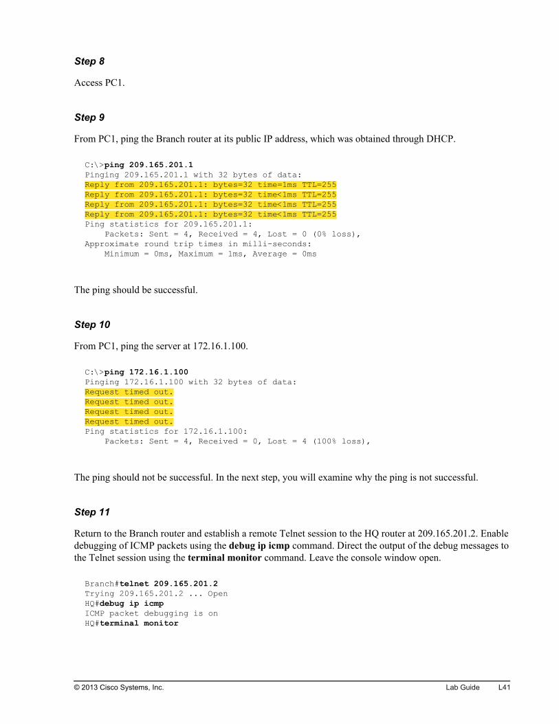
Step 9
From PC1, ping the Branch router at its public IP address, which was obtained through DHCP.
C:\>ping 209.165.201.1Pinging 209.165.201.1 with 32 bytes of data:Reply from 209.165.201.1: bytes=32 time=1ms TTL=255Reply from 209.165.201.1: bytes=32 time<1ms TTL=255Reply from 209.165.201.1: bytes=32 time<1ms TTL=255Reply from 209.165.201.1: bytes=32 time<1ms TTL=255Ping statistics for 209.165.201.1: Packets: Sent = 4, Received = 4, Lost = 0 (0% loss),Approximate round trip times in milli-seconds: Minimum = 0ms, Maximum = 1ms, Average = 0ms
The ping should be successful.
Step 10
From PC1, ping the server at 172.16.1.100.
C:\>ping 172.16.1.100Pinging 172.16.1.100 with 32 bytes of data:Request timed out.Request timed out.Request timed out.Request timed out.Ping statistics for 172.16.1.100: Packets: Sent = 4, Received = 0, Lost = 4 (100% loss),
The ping should not be successful. In the next step, you will examine why the ping is not successful.
Step 11
Return to the Branch router and establish a remote Telnet session to the HQ router at 209.165.201.2. Enabledebugging of ICMP packets using the debug ip icmp command. Direct the output of the debug messages tothe Telnet session using the terminal monitor command. Leave the console window open.
Branch#telnet 209.165.201.2Trying 209.165.201.2 ... OpenHQ#debug ip icmp ICMP packet debugging is onHQ#terminal monitor
© 2013 Cisco Systems, Inc. Lab Guide L41
Note Establishing remote Telnet sessions and redirecting output of the debug messages to a remote sessionhas not been discussed so far. In this task, it is needed only to verify that packets from PC1 actuallyreach the HQ router.
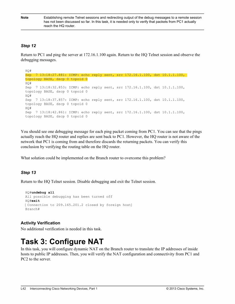
Step 12
Return to PC1 and ping the server at 172.16.1.100 again. Return to the HQ Telnet session and observe thedebugging messages.
HQ#Sep 7 13:18:27.881: ICMP: echo reply sent, src 172.16.1.100, dst 10.1.1.100, topology BASE, dscp 0 topoid 0HQ#Sep 7 13:18:32.853: ICMP: echo reply sent, src 172.16.1.100, dst 10.1.1.100, topology BASE, dscp 0 topoid 0HQ#Sep 7 13:18:37.857: ICMP: echo reply sent, src 172.16.1.100, dst 10.1.1.100, topology BASE, dscp 0 topoid 0HQ#Sep 7 13:18:42.861: ICMP: echo reply sent, src 172.16.1.100, dst 10.1.1.100, topology BASE, dscp 0 topoid 0
You should see one debugging message for each ping packet coming from PC1. You can see that the pingsactually reach the HQ router and replies are sent back to PC1. However, the HQ router is not aware of thenetwork that PC1 is coming from and therefore discards the returning packets. You can verify thisconclusion by verifying the routing table on the HQ router.
What solution could be implemented on the Branch router to overcome this problem?
Step 13
Return to the HQ Telnet session. Disable debugging and exit the Telnet session.
HQ#undebug allAll possible debugging has been turned offHQ#exit[Connection to 209.165.201.2 closed by foreign host]Branch#
Activity VerificationNo additional verification is needed in this task.
Task 3: Configure NATIn this task, you will configure dynamic NAT on the Branch router to translate the IP addresses of insidehosts to public IP addresses. Then, you will verify the NAT configuration and connectivity from PC1 andPC2 to the server.
L42 Interconnecting Cisco Networking Devices, Part 1 © 2013 Cisco Systems, Inc.
Activity ProcedureComplete the following steps:
Step 1
Access the Branch router.
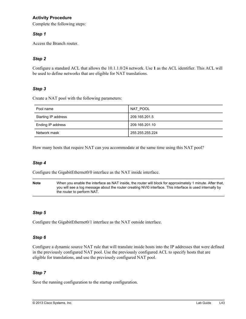
Step 2
Configure a standard ACL that allows the 10.1.1.0/24 network. Use 1 as the ACL identifier. This ACL willbe used to define networks that are eligible for NAT translations.
Step 3
Create a NAT pool with the following parameters:
Pool name NAT_POOL
Starting IP address 209.165.201.5
Ending IP address 209.165.201.10
Network mask 255.255.255.224
How many hosts that require NAT can you accommodate at the same time using this NAT pool?
Step 4
Configure the GigabitEthernet0/0 interface as the NAT inside interface.
Note When you enable the interface as NAT inside, the router will block for approximately 1 minute. After that,you will see a log message about the router creating NVI0 interface. This interface is used internally bythe router to perform NAT.
Step 5
Configure the GigabitEthernet0/1 interface as the NAT outside interface.
Step 6
Configure a dynamic source NAT rule that will translate inside hosts into the IP addresses that were definedin the previously configured NAT pool. Use the previously configured ACL to specify hosts that areeligible for translations, and use the previously configured NAT pool.
Step 7
Save the running configuration to the startup configuration.
© 2013 Cisco Systems, Inc. Lab Guide L43
Activity VerificationYou have completed this task when you attain these results:
Step 1
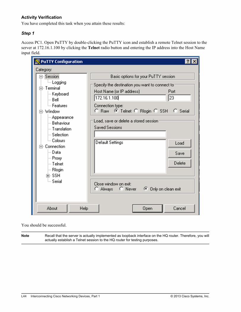
Access PC1. Open PuTTY by double-clicking the PuTTY icon and establish a remote Telnet session to theserver at 172.16.1.100 by clicking the Telnet radio button and entering the IP address into the Host Nameinput field.
You should be successful.
Note Recall that the server is actually implemented as loopback interface on the HQ router. Therefore, you willactually establish a Telnet session to the HQ router for testing purposes.
L44 Interconnecting Cisco Networking Devices, Part 1 © 2013 Cisco Systems, Inc.
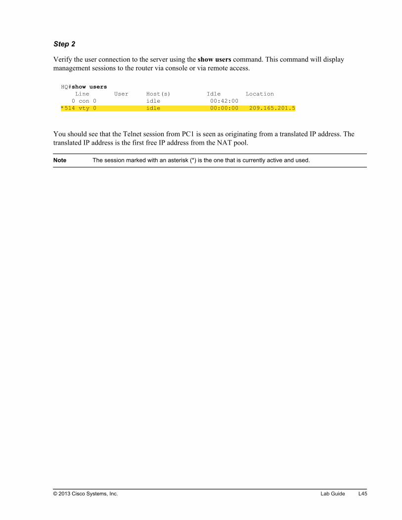
Step 2
Verify the user connection to the server using the show users command. This command will displaymanagement sessions to the router via console or via remote access.
HQ#show users Line User Host(s) Idle Location 0 con 0 idle 00:42:00*514 vty 0 idle 00:00:00 209.165.201.5
You should see that the Telnet session from PC1 is seen as originating from a translated IP address. Thetranslated IP address is the first free IP address from the NAT pool.
Note The session marked with an asterisk (*) is the one that is currently active and used.
© 2013 Cisco Systems, Inc. Lab Guide L45
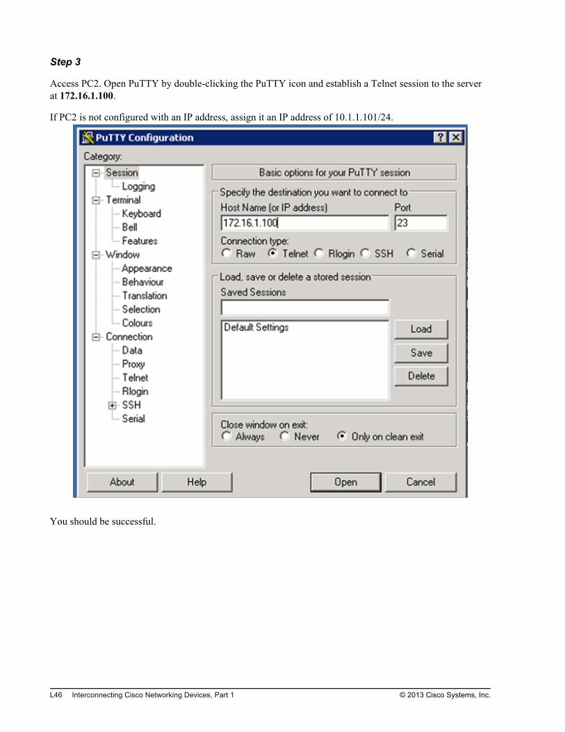
Step 3
Access PC2. Open PuTTY by double-clicking the PuTTY icon and establish a Telnet session to the serverat 172.16.1.100.
If PC2 is not configured with an IP address, assign it an IP address of 10.1.1.101/24.
You should be successful.
L46 Interconnecting Cisco Networking Devices, Part 1 © 2013 Cisco Systems, Inc.

Step 4
Verify the user connection to the server using the show users command.
HQ#show users Line User Host(s) Idle Location 514 vty 0 idle 00:00:29 209.165.201.5*515 vty 1 idle 00:00:00 209.165.201.6
You should see that the Telnet session from PC2 is seen as originating from a translated IP address. Thetranslated IP address is the next free IP address from the NAT pool.
Step 5
Return to the Branch router. Verify that there are active NAT translations.
Branch#show ip nat translations Pro Inside global Inside local Outside local Outside globaltcp 209.165.201.5:1035 10.1.1.100:1035 172.16.1.100:23 172.16.1.100:23--- 209.165.201.5 10.1.1.100 --- ---tcp 209.165.201.6:1030 10.1.1.101:1030 172.16.1.100:23 172.16.1.100:23--- 209.165.201.6 10.1.1.101 --- ---
Notice that inside local IP addresses are translated into inside global IP addresses.
Step 6
Close the Telnet session on PC1 and PC2.
Task 4: Configure NAT with PATIn this task, you will configure dynamic NAT with PAT on the Branch router to translate the IP addressesof inside hosts to the public IP address of the Branch router. Then you will verify the NAT configurationand connectivity from PC1 and PC2 to the server.
Activity ProcedureComplete the following steps:
Step 1
Return to the Branch router.
Step 2
Remove the previously configured dynamic NAT rule.
© 2013 Cisco Systems, Inc. Lab Guide L47
Step 3
Configure a dynamic source NAT/PAT (NAT with overload) rule that will translate inside hosts into the IPaddress of the router outside interface. Use the previously configured ACL to specify the hosts that areeligible for translations.
How many hosts that require NAT can you accommodate at the same time by overloading the IP address ofthe interface?
Step 4
Save the running configuration to the startup configuration.
Activity VerificationYou have completed this task when you attain these results:
L48 Interconnecting Cisco Networking Devices, Part 1 © 2013 Cisco Systems, Inc.
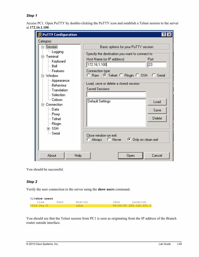
Step 1
Access PC1. Open PuTTY by double-clicking the PuTTY icon and establish a Telnet session to the serverat 172.16.1.100.
You should be successful.
Step 2
Verify the user connection to the server using the show users command.
HQ#show users Line User Host(s) Idle Location*514 vty 0 idle 00:00:00 209.165.201.1
You should see that the Telnet session from PC1 is seen as originating from the IP address of the Branchrouter outside interface.
© 2013 Cisco Systems, Inc. Lab Guide L49
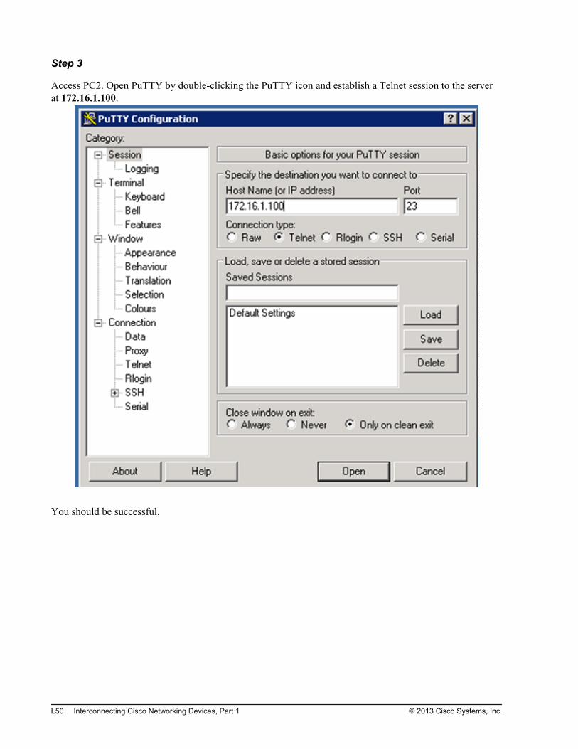
Step 3
Access PC2. Open PuTTY by double-clicking the PuTTY icon and establish a Telnet session to the serverat 172.16.1.100.
You should be successful.
L50 Interconnecting Cisco Networking Devices, Part 1 © 2013 Cisco Systems, Inc.
Step 4
Verify the user connection to the server using the show users command.
HQ#show users Line User Host(s) Idle Location 514 vty 0 idle 00:01:05 209.165.201.1*515 vty 1 idle 00:00:00 209.165.201.1
You should see that the Telnet session from PC2 is again seen as originating from the IP address of theBranch router outside interface.
Step 5
Return to the Branch router. Verify that there are active NAT translations.
Branch#show ip nat translations Pro Inside global Inside local Outside local Outside globaltcp 209.165.201.1:1042 10.1.1.100:1042 172.16.1.100:23 172.16.1.100:23tcp 209.165.201.1:1036 10.1.1.101:1036 172.16.1.100:23 172.16.1.100:23
Notice that two inside local IP addresses are translated into the same inside global IP address, which isconfigured on the Branch router outside interface. To provide two distinct translations, different sourceports are used.
Step 6
Close the Telnet session on PC1 and PC2.
© 2013 Cisco Systems, Inc. Lab Guide L51

L52 Interconnecting Cisco Networking Devices, Part 1 © 2013 Cisco Systems, Inc.

Lab 3-1: Enhancing theSecurity of the InitialConfiguration
Activity OverviewObjectivesSecuring administrative access to devices is crucial because you do not want unauthorized users to haveaccess to your network devices. In this lab, you will increase the security of the initial switch and routerconfiguration. After you have completed this activity, you will be able to meet these objectives:
Configure passwords on a router and switch
Configure and limit remote access to SSH
Configure an ACL to limit remote access
Configure the login banner
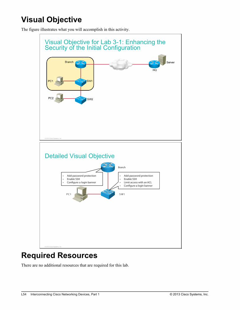
Visual ObjectiveThe figure illustrates what you will accomplish in this activity.
Visual Objective for Lab 3-1: Enhancing theSecurity of the Initial Configuration
© 2013 Cisco Systems, Inc.
Detailed Visual ObjectiveBranch
1WS1CP
• Add password protection
• Enable SSH
• Con!gure a login banner
• Add password protection
• Enable SSH
• Limit access with an ACL
• Con!gure a login banner
© 2013 Cisco Systems, Inc.
Required ResourcesThere are no additional resources that are required for this lab.
L54 Interconnecting Cisco Networking Devices, Part 1 © 2013 Cisco Systems, Inc.

Command ListThe table describes the commands that are used in this activity. The commands are listed in alphabeticalorder so that you can easily locate the information that you need. Refer to this list if you need configurationcommand assistance during the lab activity.
CommandsCommand Description
access-class number direction Applies the ACL to the vty line. The direction argument can have thevalue of either in or out.
access-list number permit ip_addresswildcard_mask
Creates a standard ACL that permits all traffic from or to a specifiednetwork.
banner login Allows the configuration of a message that is displayed just beforelogin.
copy running-config startup-config Copies the switch running configuration file to the startup configurationfile that is held in local NVRAM.
crypto key generate rsa Generates the RSA key pairs to be used.
enable secret password Sets a password for entering privileged EXEC mode. The password isprotected using strong MD5-type encryption.
end Terminates configuration mode.
ip domain-name name Supplies an IP domain name that is required by the cryptographic key-generation process.
ip ssh version [1 | 2] Specifies the version of SSH to be run. To disable the version of SSHthat was configured and to return to compatibility mode, use the noform of this command.
line console 0 Enters line console 0 configuration mode.
line vty start_number end_number Enters vty configuration mode. Vty lines allow access to the switch forremote network management. The number of vty lines available isdependent on the Cisco IOS Software version. Typical values are 0-4and 0-15 (inclusive).
login Activates the login process on the console or vty lines.
login local Makes the login process on the console or vty lines rely on (or use)the local authentication database.
logout Exits EXEC mode and requires reauthentication (if enabled).
password Assigns a password to the console or vty lines.
show access-list Displays all ACLs that are defined on the device.
show running-config Displays the active configuration.
show users Displays information about the active lines.
ssh –l username ip_address Starts an encrypted session with a remote networking device using thecurrent user ID. The IP address identifies the destination device.
© 2013 Cisco Systems, Inc. Lab Guide L55
Command Description
transport input [telnet | ssh | all] Specifies which protocols to use to connect to a specific line of thedevice.
username username secret password Creates a username and password pair that can then be used as alocal authentication database.
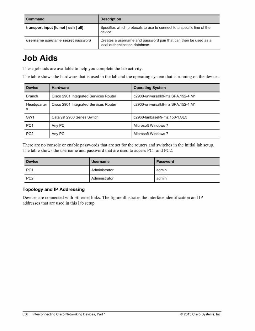
Job AidsThese job aids are available to help you complete the lab activity.
The table shows the hardware that is used in the lab and the operating system that is running on the devices.
Device Hardware Operating System
Branch Cisco 2901 Integrated Services Router c2900-universalk9-mz.SPA.152-4.M1
Headquarters
Cisco 2901 Integrated Services Router c2900-universalk9-mz.SPA.152-4.M1
SW1 Catalyst 2960 Series Switch c2960-lanbasek9-mz.150-1.SE3
PC1 Any PC Microsoft Windows 7
PC2 Any PC Microsoft Windows 7
There are no console or enable passwords that are set for the routers and switches in the initial lab setup.The table shows the username and password that are used to access PC1 and PC2.
Device Username Password
PC1 Administrator admin
PC2 Administrator admin
Topology and IP Addressing
Devices are connected with Ethernet links. The figure illustrates the interface identification and IPaddresses that are used in this lab setup.
L56 Interconnecting Cisco Networking Devices, Part 1 © 2013 Cisco Systems, Inc.
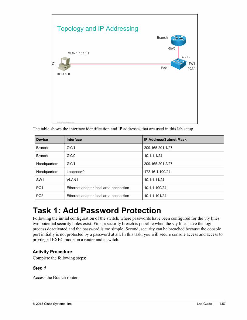
Topology and IP Addressing
PC1 SW1
Branch
Fa0/1
Gi0/0
Fa0/13
10.1.1.100
10.1.1.11
VLAN 1: 10.1.1.1
© 2013 Cisco Systems, Inc.
The table shows the interface identification and IP addresses that are used in this lab setup.
Device Interface IP Address/Subnet Mask
Branch Gi0/1 209.165.201.1/27
Branch Gi0/0 10.1.1.1/24
Headquarters Gi0/1 209.165.201.2/27
Headquarters Loopback0 172.16.1.100/24
SW1 VLAN1 10.1.1.11/24
PC1 Ethernet adapter local area connection 10.1.1.100/24
PC2 Ethernet adapter local area connection 10.1.1.101/24
Task 1: Add Password ProtectionFollowing the initial configuration of the switch, where passwords have been configured for the vty lines,two potential security holes exist. First, a security breach is possible when the vty lines have the loginprocess deactivated and the password is too simple. Second, security can be breached because the consoleport initially is not protected by a password at all. In this task, you will secure console access and access toprivileged EXEC mode on a router and a switch.
Activity ProcedureComplete the following steps:
Step 1
Access the Branch router.
© 2013 Cisco Systems, Inc. Lab Guide L57
Step 2
Secure the console line with the password cisco.
Step 3
Exit to the console login screen by issuing the end and exit commands.
You will be asked for the password that you configured in the previous step.
Branch(config-line)# endBranch# exitBranch con0 is now availablePress RETURN to get started.User Access VerificationPassword:Branch>
Step 4
Examine the running configuration and identify the password that was configured for the console line. Notethat the password is in cleartext.
Branch# show running-config | section line conline con 0 exec-timeout 60 0 password cisco logging synchronous login
Step 5
Create the username ccna and assign the secret password cisco to it. Look at the Command List section toidentify the correct command.
Then change the mode of authentication on the console line so that this user is authenticated using thisusername and password.
L58 Interconnecting Cisco Networking Devices, Part 1 © 2013 Cisco Systems, Inc.

Step 6
Exit to the console login screen by issuing the end and exit commands.
You will be asked for a username and password. Enter the credentials that you created in the previous step.
Branch(config-line)# endBranch# exitBranch con0 is now availablePress RETURN to get started.User Access VerificationUsername: ccnaPassword:Branch>
Step 7
Examine the running configuration and identify the username and password that you created.
Note that the password is encrypted, not in cleartext. You could use the service password-encryptioncommand to encode the cleartext password, but this encryption type is weak.
Branch# show running-config | section usernameusername ccna secret 4 tnhtc92DXBhelxjYk8LWJrPV36S2i4ntXrpb4RFmfqY
Step 8
Secure vty lines 0 through 15. Users should be able to log in using the username ccna and password ciscothat you previously defined.
For security reasons, the passwords for console and vty access should be different. Also, in productionenvironments, you should use strong passwords (at least eight characters and a combination of letters,numbers, and special characters). In the lab environment, we are using the same passwords for console andvty access.
© 2013 Cisco Systems, Inc. Lab Guide L59
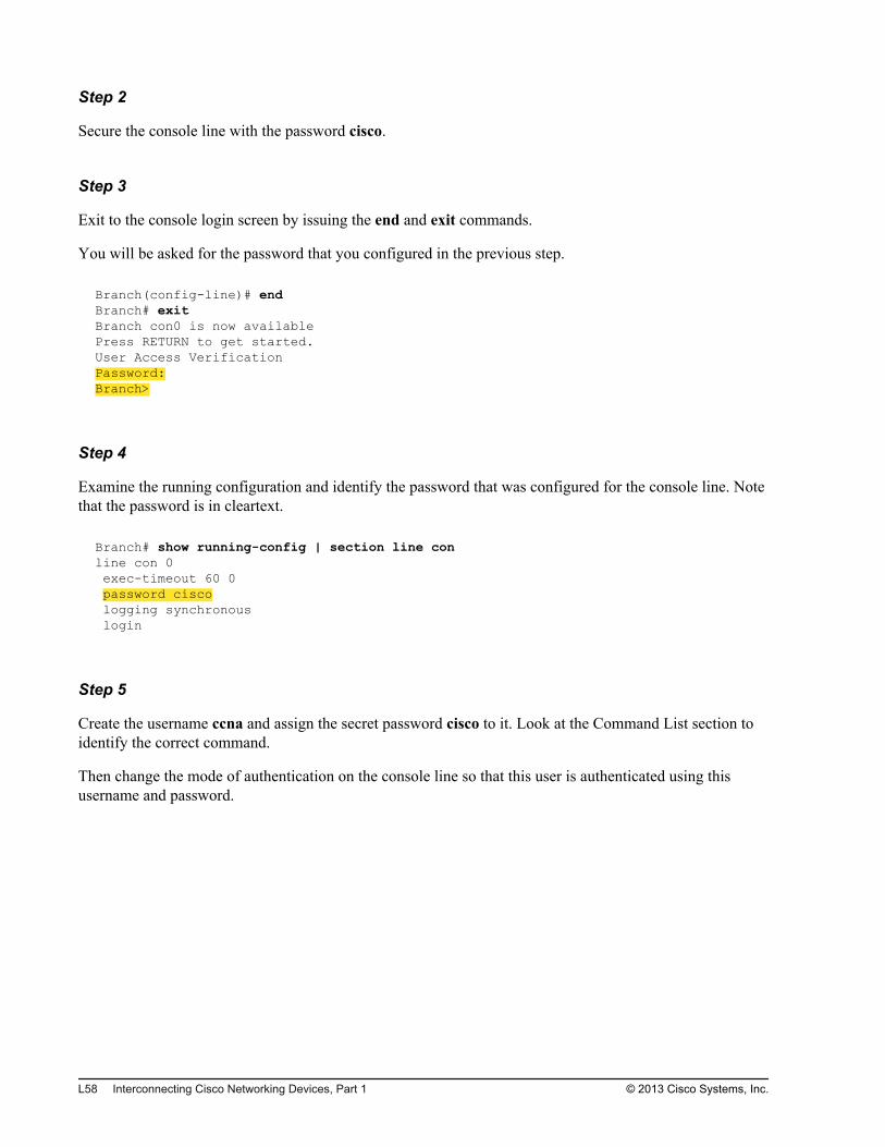
Step 9
On PC1, open PuTTY and establish a Telnet session to the Branch router to verify that you configured vtysecurity correctly.
Enter the appropriate credentials to log into the Branch router.
L60 Interconnecting Cisco Networking Devices, Part 1 © 2013 Cisco Systems, Inc.
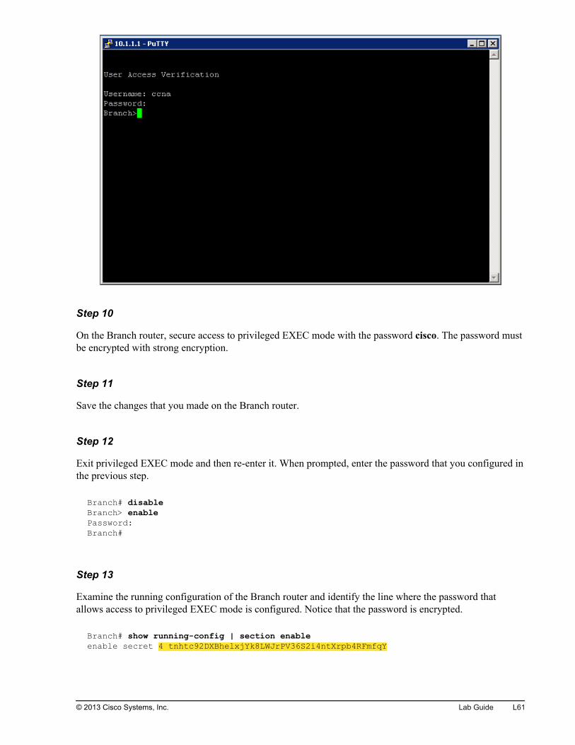
Step 10
On the Branch router, secure access to privileged EXEC mode with the password cisco. The password mustbe encrypted with strong encryption.
Step 11
Save the changes that you made on the Branch router.
Step 12
Exit privileged EXEC mode and then re-enter it. When prompted, enter the password that you configured inthe previous step.
Branch# disableBranch> enablePassword:Branch#
Step 13
Examine the running configuration of the Branch router and identify the line where the password thatallows access to privileged EXEC mode is configured. Notice that the password is encrypted.
Branch# show running-config | section enableenable secret 4 tnhtc92DXBhelxjYk8LWJrPV36S2i4ntXrpb4RFmfqY
© 2013 Cisco Systems, Inc. Lab Guide L61
Step 14
Access switch SW1. Configure it with the enable secret password cisco. Users should be able to log into theconsole and vty lines by using the username ccna and the password cisco. Use strong encryption.
Step 15
Save the changes that you made on the SW1 switch.
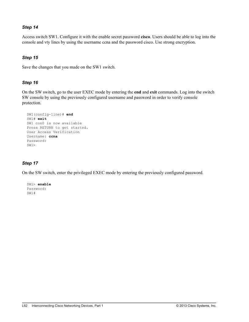
Step 16
On the SW switch, go to the user EXEC mode by entering the end and exit commands. Log into the switchSW console by using the previously configured username and password in order to verify consoleprotection.
SW1(config-line)# endSW1# exitSW1 con0 is now availablePress RETURN to get started.User Access VerificationUsername: ccnaPassword: SW1>
Step 17
On the SW switch, enter the privileged EXEC mode by entering the previously configured password.
SW1> enablePassword: SW1#
L62 Interconnecting Cisco Networking Devices, Part 1 © 2013 Cisco Systems, Inc.
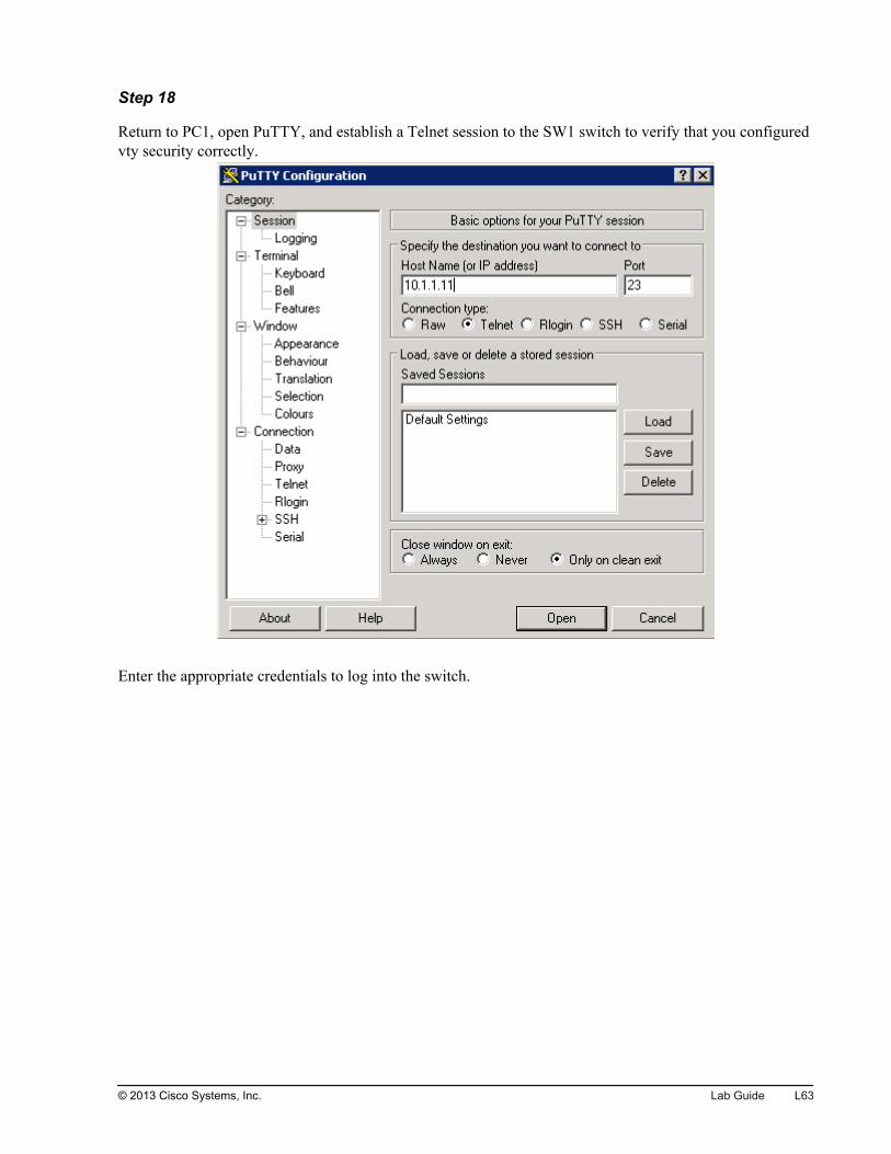
Step 18
Return to PC1, open PuTTY, and establish a Telnet session to the SW1 switch to verify that you configuredvty security correctly.
Enter the appropriate credentials to log into the switch.
© 2013 Cisco Systems, Inc. Lab Guide L63
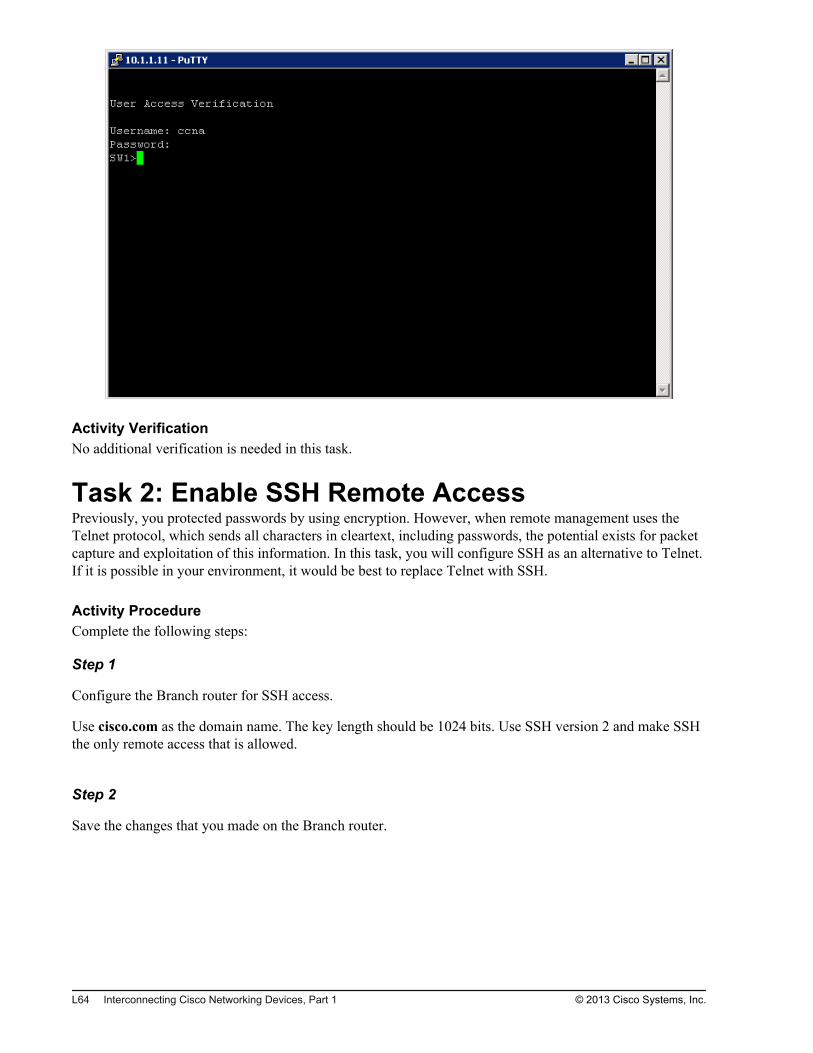
Activity VerificationNo additional verification is needed in this task.
Task 2: Enable SSH Remote AccessPreviously, you protected passwords by using encryption. However, when remote management uses theTelnet protocol, which sends all characters in cleartext, including passwords, the potential exists for packetcapture and exploitation of this information. In this task, you will configure SSH as an alternative to Telnet.If it is possible in your environment, it would be best to replace Telnet with SSH.
Activity ProcedureComplete the following steps:
Step 1
Configure the Branch router for SSH access.
Use cisco.com as the domain name. The key length should be 1024 bits. Use SSH version 2 and make SSHthe only remote access that is allowed.
Step 2
Save the changes that you made on the Branch router.
L64 Interconnecting Cisco Networking Devices, Part 1 © 2013 Cisco Systems, Inc.
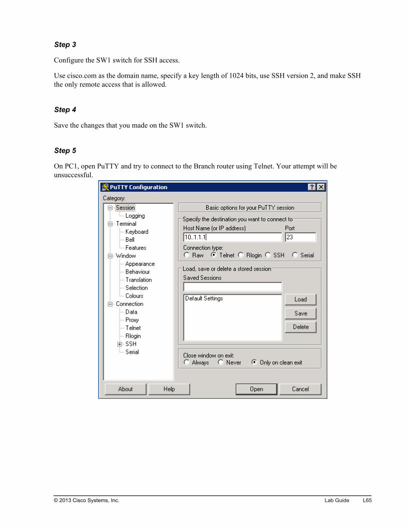
Step 3
Configure the SW1 switch for SSH access.
Use cisco.com as the domain name, specify a key length of 1024 bits, use SSH version 2, and make SSHthe only remote access that is allowed.
Step 4
Save the changes that you made on the SW1 switch.
Step 5
On PC1, open PuTTY and try to connect to the Branch router using Telnet. Your attempt will beunsuccessful.
© 2013 Cisco Systems, Inc. Lab Guide L65
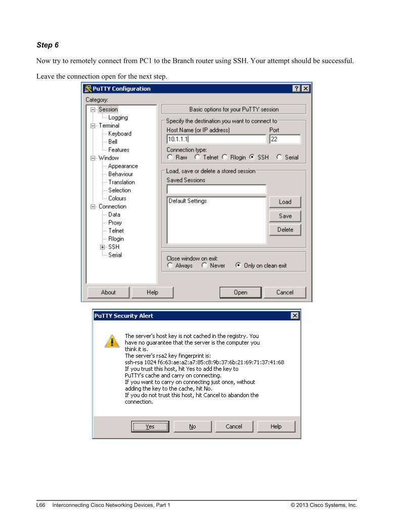
Step 6
Now try to remotely connect from PC1 to the Branch router using SSH. Your attempt should be successful.
Leave the connection open for the next step.
L66 Interconnecting Cisco Networking Devices, Part 1 © 2013 Cisco Systems, Inc.
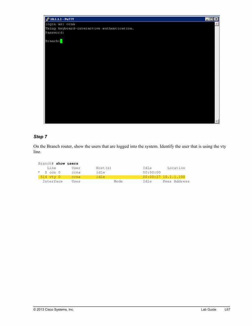
Step 7
On the Branch router, show the users that are logged into the system. Identify the user that is using the vtyline.
Branch# show users Line User Host(s) Idle Location* 0 con 0 ccna idle 00:00:00 514 vty 0 ccna idle 00:00:27 10.1.1.100 Interface User Mode Idle Peer Address
© 2013 Cisco Systems, Inc. Lab Guide L67
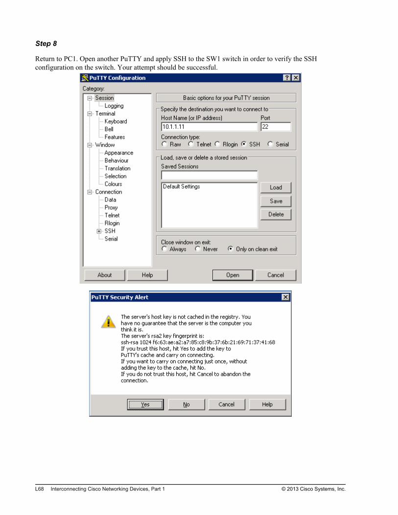
Step 8
Return to PC1. Open another PuTTY and apply SSH to the SW1 switch in order to verify the SSHconfiguration on the switch. Your attempt should be successful.
L68 Interconnecting Cisco Networking Devices, Part 1 © 2013 Cisco Systems, Inc.
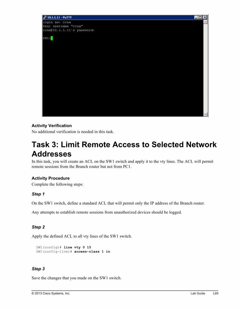
Activity VerificationNo additional verification is needed in this task.
Task 3: Limit Remote Access to Selected NetworkAddressesIn this task, you will create an ACL on the SW1 switch and apply it to the vty lines. The ACL will permitremote sessions from the Branch router but not from PC1.
Activity ProcedureComplete the following steps:
Step 1
On the SW1 switch, define a standard ACL that will permit only the IP address of the Branch router.
Any attempts to establish remote sessions from unauthorized devices should be logged.
Step 2
Apply the defined ACL to all vty lines of the SW1 switch.
SW1(config)# line vty 0 15SW1(config-line)# access-class 1 in
Step 3
Save the changes that you made on the SW1 switch.
© 2013 Cisco Systems, Inc. Lab Guide L69
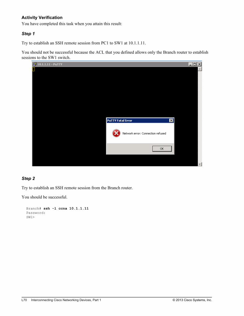
Activity VerificationYou have completed this task when you attain this result:
Step 1
Try to establish an SSH remote session from PC1 to SW1 at 10.1.1.11.
You should not be successful because the ACL that you defined allows only the Branch router to establishsessions to the SW1 switch.
Step 2
Try to establish an SSH remote session from the Branch router.
You should be successful.
Branch# ssh -l ccna 10.1.1.11Password:SW1>
L70 Interconnecting Cisco Networking Devices, Part 1 © 2013 Cisco Systems, Inc.

Step 3
On the SW1 switch, show the ACL that you defined for the vty lines.
Notice that the counters for both the permit and deny statements increased. If you did not define an explicitdeny statement, a remote session from PC1 would still be denied, but you would not be able to see countersfor denied remote session attempts.
SW1# show access-listsStandard IP access list 1 10 permit 10.1.1.1 (2 matches) 20 deny any log (3 matches)
Task 4: Configure a Login BannerAs part of any security policy, you must ensure that network resources are clearly identified as being offlimits to the casual visitor. Hackers have successfully used the fact that a “welcome” screen was presentedat login as their legal defense for forced entry into the network. Therefore, a message that clearly states thataccess is restricted should be presented when a user is attempting to access a network device (switch, router,and so on). The Cisco IOS banner command allows you to do so.
Activity ProcedureComplete the following steps:
Step 1
Configure the Branch router with the following login banner message:
********** Warning *************Access to this device is restricted to authorized persons only!Unauthorized access is prohibited. Violators will be prosecuted.***********************************************
Step 2
Save the changes that you made on the Branch router.
Step 3
Configure the SW1 switch with the same login banner that you used for the Branch router in the previousstep:
********** Warning *************Access to this device is restricted to authorized persons only!Unauthorized access is prohibited. Violators will be prosecuted.***********************************************
© 2013 Cisco Systems, Inc. Lab Guide L71
Step 4
Save the changes that you made on the SW1 switch.
Activity VerificationYou have completed this task when you attain these results:
Step 1
Access the Branch router. Log out of the Branch router and then log back in.
Notice the login banner that you were presented with as you logged in.
Branch# logoutBranch con0 is now availablePress RETURN to get started.********** Warning *************Access to this device is restricted to authorized persons only!Unauthorized access is prohibited. Violators will be prosecuted.***********************************************User Access VerificationUsername: ccnaPassword:
Step 2
Access SW1. Log out of the SW1 switch console and then log back in.
Notice the login banner that you were presented with as you logged in.
SW1# logoutSW1 con0 is now availablePress RETURN to get started.********** Warning *************Access to this device is restricted to authorized persons only!Un-authorized access is prohibited. Violators will be prosecuted.***********************************************User Access VerificationUsername: ccnaPassword:
Note When accessing network devices via the SSH protocol, some terminal clients such as PuTTY display thelogin banner only after the username parameter is entered as input.
L72 Interconnecting Cisco Networking Devices, Part 1 © 2013 Cisco Systems, Inc.
Lab 3-2: Device Hardening
Activity OverviewObjectivesDevice hardening is crucial to increasing security in the network. In this lab, you will perform securitydevice hardening on a router and switch. After you have completed this activity, you will be able to meetthese objectives:
Disable unused ports
Configure port security on a switch
Disable unused services
Configure NTP
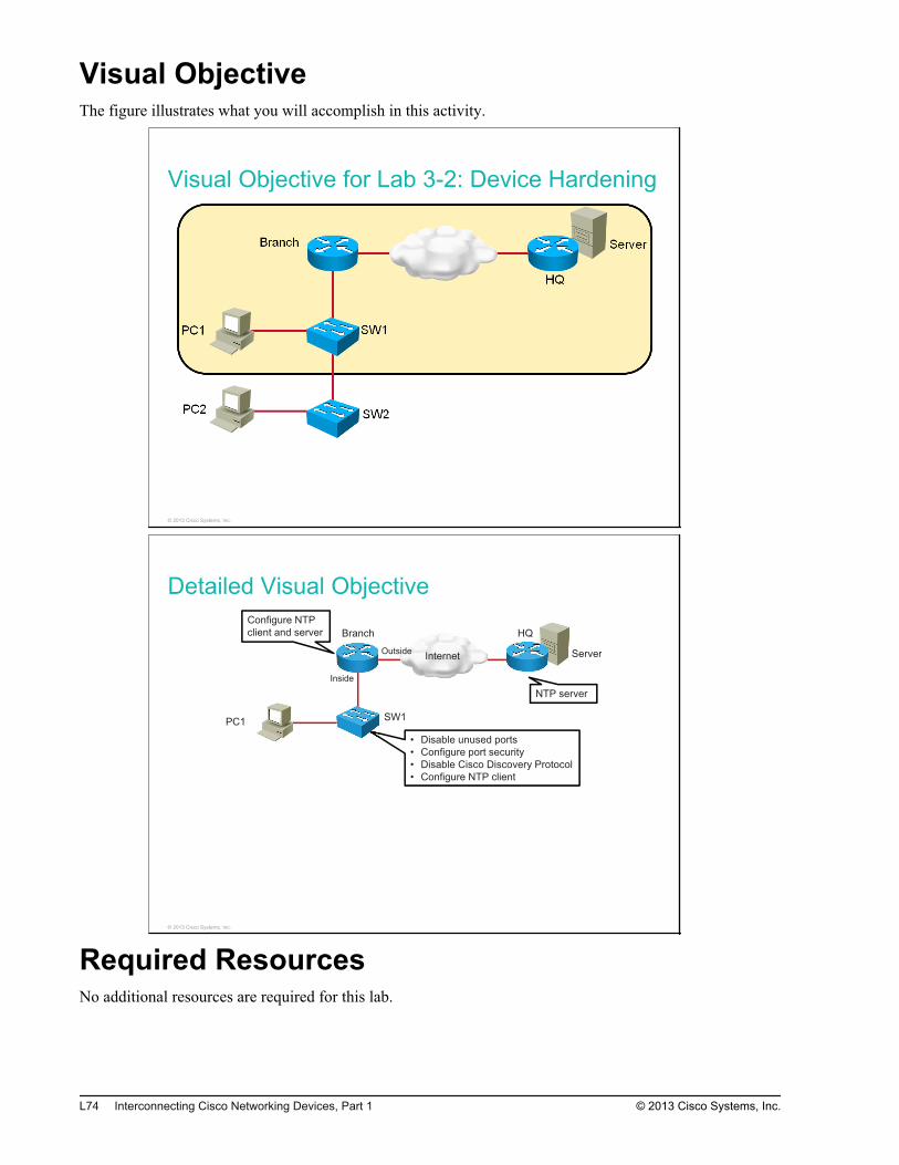
Visual ObjectiveThe figure illustrates what you will accomplish in this activity.
Visual Objective for Lab 3-2: Device Hardening
© 2013 Cisco Systems, Inc.
Detailed Visual Objective
• Disable unused ports
• Configure port security
• Disable Cisco Discovery Protocol
• Configure NTP client
Internet Server
PC1 SW1
QHhcnarB
Configure NTP
client and server
Inside
Outside
NTP server
© 2013 Cisco Systems, Inc.
Required ResourcesNo additional resources are required for this lab.
L74 Interconnecting Cisco Networking Devices, Part 1 © 2013 Cisco Systems, Inc.

Command ListThe table that follows describes the commands that are used in this activity. The commands are listed inalphabetical order so that you can easily locate the information that you need. Refer to this list if you needconfiguration command assistance during the lab activity.
CommandsCommand Description
[no] cdp enable Enables or disables Cisco Discovery Protocol on an interface
configure terminal Enters configuration mode
interface interface Enters interface configuration mode
ntp master [stratum] Configures Cisco IOS Software as an NTP master clock.
ntp server {ip-address} Allows the software clock to be synchronized by an NTP time server
ping dest_IP Verifies connectivity between the source IP and destination IP
show cdp neighbors Displays detailed information about neighboring devices that arediscovered by using Cisco Discovery Protocol
show interfaces Displays statistics for all interfaces that are configured on the router
show interfaces status Displays the status of interfaces
show port-security interface interface Displays the port security settings that are defined for an interface
show ntp associations Displays the status of NTP associations
show ntp status Displays the status of NTP
show port-security address Displays the secure MAC addresses for all ports
[no] shutdown Enables or disables an interface on the router
switchport mode access Configures a switchport as an access port
switchport port-security Enables the port security feature on the interface
switchport port-security mac-addressmac-address
Enters a secure MAC address for the interface
Job AidsThese job aids are available to help you complete the lab activity.
The table shows the hardware that is used in the lab and the operating system that is running on the devices.
Device Hardware Operating System
Branch Cisco 2901 Integrated Services Router c2900-universalk9-mz.SPA.152-4.M1
Headquarters
Cisco 2901 Integrated Services Router c2900-universalk9-mz.SPA.152-4.M1
SW1 Catalyst 2960 Series Switch c2960-lanbasek9-mz.150-1.SE3
© 2013 Cisco Systems, Inc. Lab Guide L75
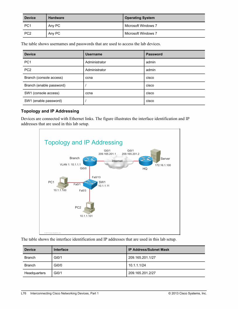
Device Hardware Operating System
PC1 Any PC Microsoft Windows 7
PC2 Any PC Microsoft Windows 7
The table shows usernames and passwords that are used to access the lab devices.
Device Username Password
PC1 Administrator admin
PC2 Administrator admin
Branch (console access) ccna cisco
Branch (enable password) / cisco
SW1 (console access) ccna cisco
SW1 (enable password) / cisco
Topology and IP Addressing
Devices are connected with Ethernet links. The figure illustrates the interface identification and IPaddresses that are used in this lab setup.
Topology and IP Addressing
InternetServer
PC1
PC2
SW1
Branch
HQ
Fa0/1
Gi0/0
Fa0/13
Fa0/3
Gi0/1
209.165.201.1
Gi0/1
209.165.201.2
10.1.1.100
10.1.1.101
10.1.1.11
VLAN 1: 10.1.1.1 172.16.1.100
0/3
© 2013 Cisco Systems, Inc.
The table shows the interface identification and IP addresses that are used in this lab setup.
Device Interface IP Address/Subnet Mask
Branch Gi0/1 209.165.201.1/27
Branch Gi0/0 10.1.1.1/24
Headquarters Gi0/1 209.165.201.2/27
L76 Interconnecting Cisco Networking Devices, Part 1 © 2013 Cisco Systems, Inc.
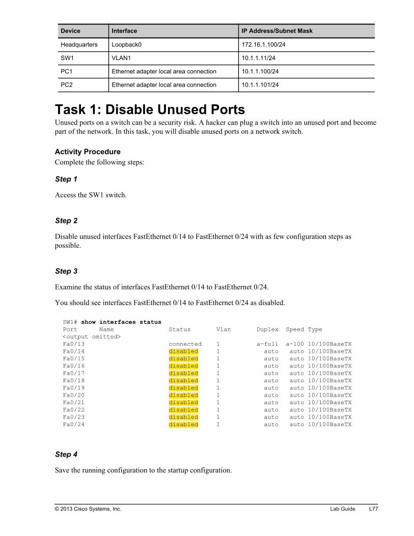
Device Interface IP Address/Subnet Mask
Headquarters Loopback0 172.16.1.100/24
SW1 VLAN1 10.1.1.11/24
PC1 Ethernet adapter local area connection 10.1.1.100/24
PC2 Ethernet adapter local area connection 10.1.1.101/24
Task 1: Disable Unused PortsUnused ports on a switch can be a security risk. A hacker can plug a switch into an unused port and becomepart of the network. In this task, you will disable unused ports on a network switch.
Activity ProcedureComplete the following steps:
Step 1
Access the SW1 switch.
Step 2
Disable unused interfaces FastEthernet 0/14 to FastEthernet 0/24 with as few configuration steps aspossible.
Step 3
Examine the status of interfaces FastEthernet 0/14 to FastEthernet 0/24.
You should see interfaces FastEthernet 0/14 to FastEthernet 0/24 as disabled.
SW1# show interfaces statusPort Name Status Vlan Duplex Speed Type<output omitted>Fa0/13 connected 1 a-full a-100 10/100BaseTXFa0/14 disabled 1 auto auto 10/100BaseTXFa0/15 disabled 1 auto auto 10/100BaseTXFa0/16 disabled 1 auto auto 10/100BaseTXFa0/17 disabled 1 auto auto 10/100BaseTXFa0/18 disabled 1 auto auto 10/100BaseTXFa0/19 disabled 1 auto auto 10/100BaseTXFa0/20 disabled 1 auto auto 10/100BaseTXFa0/21 disabled 1 auto auto 10/100BaseTXFa0/22 disabled 1 auto auto 10/100BaseTXFa0/23 disabled 1 auto auto 10/100BaseTXFa0/24 disabled 1 auto auto 10/100BaseTX
Step 4
Save the running configuration to the startup configuration.
© 2013 Cisco Systems, Inc. Lab Guide L77
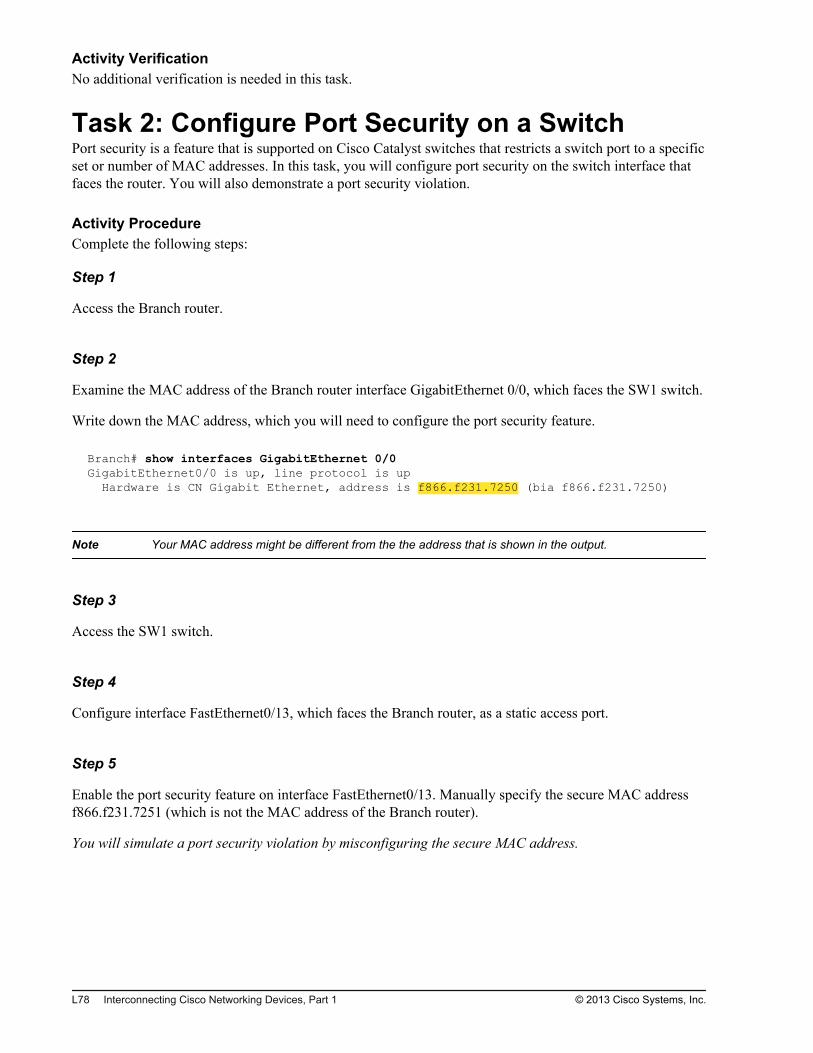
Activity VerificationNo additional verification is needed in this task.
Task 2: Configure Port Security on a SwitchPort security is a feature that is supported on Cisco Catalyst switches that restricts a switch port to a specificset or number of MAC addresses. In this task, you will configure port security on the switch interface thatfaces the router. You will also demonstrate a port security violation.
Activity ProcedureComplete the following steps:
Step 1
Access the Branch router.
Step 2
Examine the MAC address of the Branch router interface GigabitEthernet 0/0, which faces the SW1 switch.
Write down the MAC address, which you will need to configure the port security feature.
Branch# show interfaces GigabitEthernet 0/0GigabitEthernet0/0 is up, line protocol is up Hardware is CN Gigabit Ethernet, address is f866.f231.7250 (bia f866.f231.7250)
Note Your MAC address might be different from the the address that is shown in the output.
Step 3
Access the SW1 switch.
Step 4
Configure interface FastEthernet0/13, which faces the Branch router, as a static access port.
Step 5
Enable the port security feature on interface FastEthernet0/13. Manually specify the secure MAC addressf866.f231.7251 (which is not the MAC address of the Branch router).
You will simulate a port security violation by misconfiguring the secure MAC address.
L78 Interconnecting Cisco Networking Devices, Part 1 © 2013 Cisco Systems, Inc.
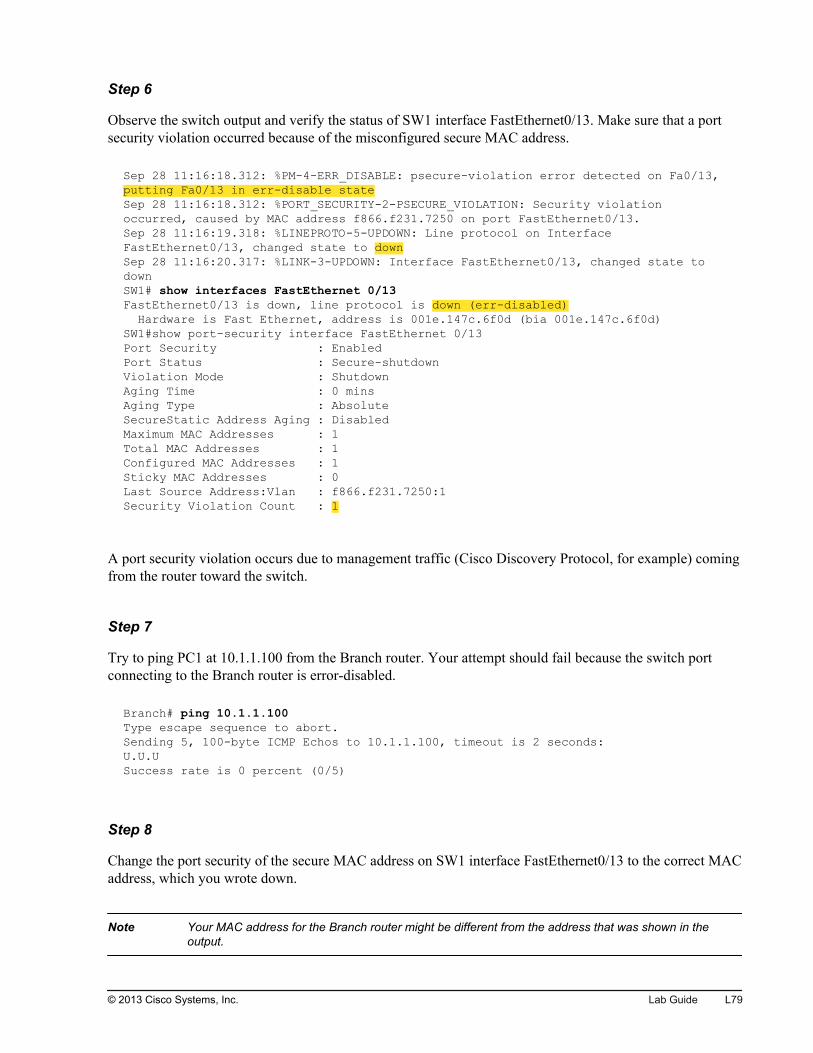
Step 6
Observe the switch output and verify the status of SW1 interface FastEthernet0/13. Make sure that a portsecurity violation occurred because of the misconfigured secure MAC address.
Sep 28 11:16:18.312: %PM-4-ERR_DISABLE: psecure-violation error detected on Fa0/13, putting Fa0/13 in err-disable stateSep 28 11:16:18.312: %PORT_SECURITY-2-PSECURE_VIOLATION: Security violation occurred, caused by MAC address f866.f231.7250 on port FastEthernet0/13.Sep 28 11:16:19.318: %LINEPROTO-5-UPDOWN: Line protocol on Interface FastEthernet0/13, changed state to downSep 28 11:16:20.317: %LINK-3-UPDOWN: Interface FastEthernet0/13, changed state to downSW1# show interfaces FastEthernet 0/13FastEthernet0/13 is down, line protocol is down (err-disabled) Hardware is Fast Ethernet, address is 001e.147c.6f0d (bia 001e.147c.6f0d)SW1#show port-security interface FastEthernet 0/13Port Security : EnabledPort Status : Secure-shutdownViolation Mode : ShutdownAging Time : 0 minsAging Type : AbsoluteSecureStatic Address Aging : DisabledMaximum MAC Addresses : 1Total MAC Addresses : 1Configured MAC Addresses : 1Sticky MAC Addresses : 0Last Source Address:Vlan : f866.f231.7250:1Security Violation Count : 1
A port security violation occurs due to management traffic (Cisco Discovery Protocol, for example) comingfrom the router toward the switch.
Step 7
Try to ping PC1 at 10.1.1.100 from the Branch router. Your attempt should fail because the switch portconnecting to the Branch router is error-disabled.
Branch# ping 10.1.1.100Type escape sequence to abort.Sending 5, 100-byte ICMP Echos to 10.1.1.100, timeout is 2 seconds:U.U.USuccess rate is 0 percent (0/5)
Step 8
Change the port security of the secure MAC address on SW1 interface FastEthernet0/13 to the correct MACaddress, which you wrote down.
Note Your MAC address for the Branch router might be different from the address that was shown in theoutput.
© 2013 Cisco Systems, Inc. Lab Guide L79
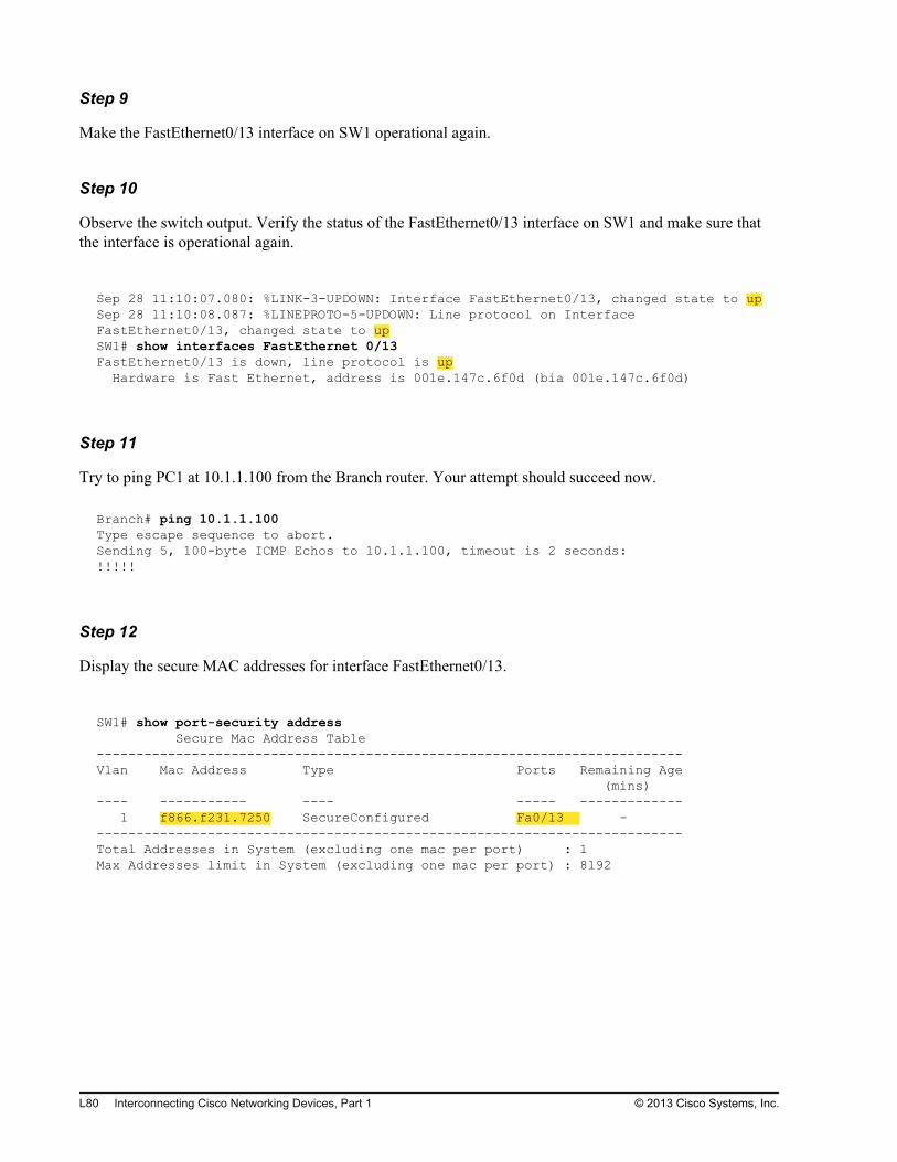
Step 9
Make the FastEthernet0/13 interface on SW1 operational again.
Step 10
Observe the switch output. Verify the status of the FastEthernet0/13 interface on SW1 and make sure thatthe interface is operational again.
Sep 28 11:10:07.080: %LINK-3-UPDOWN: Interface FastEthernet0/13, changed state to upSep 28 11:10:08.087: %LINEPROTO-5-UPDOWN: Line protocol on Interface FastEthernet0/13, changed state to upSW1# show interfaces FastEthernet 0/13FastEthernet0/13 is down, line protocol is up Hardware is Fast Ethernet, address is 001e.147c.6f0d (bia 001e.147c.6f0d)
Step 11
Try to ping PC1 at 10.1.1.100 from the Branch router. Your attempt should succeed now.
Branch# ping 10.1.1.100Type escape sequence to abort.Sending 5, 100-byte ICMP Echos to 10.1.1.100, timeout is 2 seconds:!!!!!
Step 12
Display the secure MAC addresses for interface FastEthernet0/13.
SW1# show port-security address Secure Mac Address Table--------------------------------------------------------------------------Vlan Mac Address Type Ports Remaining Age (mins)---- ----------- ---- ----- ------------- 1 f866.f231.7250 SecureConfigured Fa0/13 ---------------------------------------------------------------------------Total Addresses in System (excluding one mac per port) : 1Max Addresses limit in System (excluding one mac per port) : 8192
L80 Interconnecting Cisco Networking Devices, Part 1 © 2013 Cisco Systems, Inc.
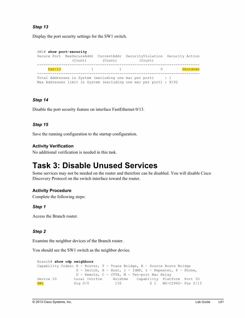
Step 13
Display the port security settings for the SW1 switch.
SW1# show port-securitySecure Port MaxSecureAddr CurrentAddr SecurityViolation Security Action (Count) (Count) (Count)--------------------------------------------------------------------------- Fa0/13 1 1 0 Shutdown---------------------------------------------------------------------------Total Addresses in System (excluding one mac per port) : 1Max Addresses limit in System (excluding one mac per port) : 8192
Step 14
Disable the port security feature on interface FastEthernet 0/13.
Step 15
Save the running configuration to the startup configuration.
Activity VerificationNo additional verification is needed in this task.
Task 3: Disable Unused ServicesSome services may not be needed on the router and therefore can be disabled. You will disable CiscoDiscovery Protocol on the switch interface toward the router.
Activity ProcedureComplete the following steps:
Step 1
Access the Branch router.
Step 2
Examine the neighbor devices of the Branch router.
You should see the SW1 switch as the neighbor device.
Branch# show cdp neighborsCapability Codes: R - Router, T - Trans Bridge, B - Source Route Bridge S - Switch, H - Host, I - IGMP, r - Repeater, P - Phone, D - Remote, C - CVTA, M - Two-port Mac RelayDevice ID Local Intrfce Holdtme Capability Platform Port IDSW1 Gig 0/0 135 S I WS-C2960- Fas 0/13
© 2013 Cisco Systems, Inc. Lab Guide L81
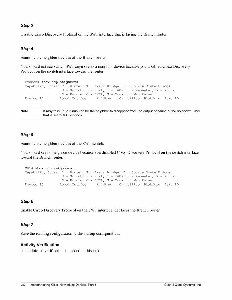
Step 3
Disable Cisco Discovery Protocol on the SW1 interface that is facing the Branch router.
Step 4
Examine the neighbor devices of the Branch router.
You should not see switch SW1 anymore as a neighbor device because you disabled Cisco DiscoveryProtocol on the switch interface toward the router.
Branch# show cdp neighborsCapability Codes: R - Router, T - Trans Bridge, B - Source Route Bridge S - Switch, H - Host, I - IGMP, r - Repeater, P - Phone, D - Remote, C - CVTA, M - Two-port Mac RelayDevice ID Local Intrfce Holdtme Capability Platform Port ID
Note It may take up to 3 minutes for the neighbor to disappear from the output because of the holddown timerthat is set to 180 seconds.
Step 5
Examine the neighbor devices of the SW1 switch.
You should see no neighbor device because you disabled Cisco Discovery Protocol on the switch interfacetoward the Branch router.
SW1# show cdp neighborsCapability Codes: R - Router, T - Trans Bridge, B - Source Route Bridge S - Switch, H - Host, I - IGMP, r - Repeater, P - Phone, D - Remote, C - CVTA, M - Two-port Mac RelayDevice ID Local Intrfce Holdtme Capability Platform Port ID
Step 6
Enable Cisco Discovery Protocol on the SW1 interface that faces the Branch router.
Step 7
Save the running configuration to the startup configuration.
Activity VerificationNo additional verification is needed in this task.
L82 Interconnecting Cisco Networking Devices, Part 1 © 2013 Cisco Systems, Inc.
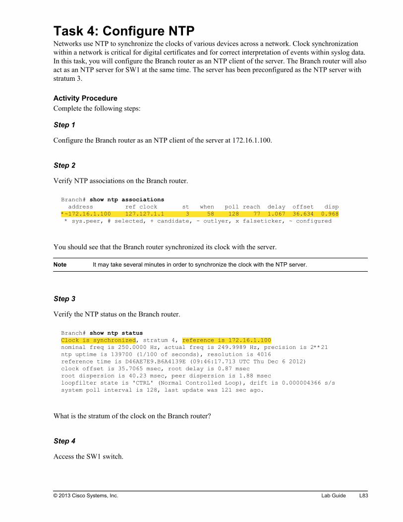
Task 4: Configure NTPNetworks use NTP to synchronize the clocks of various devices across a network. Clock synchronizationwithin a network is critical for digital certificates and for correct interpretation of events within syslog data.In this task, you will configure the Branch router as an NTP client of the server. The Branch router will alsoact as an NTP server for SW1 at the same time. The server has been preconfigured as the NTP server withstratum 3.
Activity ProcedureComplete the following steps:
Step 1
Configure the Branch router as an NTP client of the server at 172.16.1.100.
Step 2
Verify NTP associations on the Branch router.
Branch# show ntp associations address ref clock st when poll reach delay offset disp*~172.16.1.100 127.127.1.1 3 58 128 77 1.067 36.634 0.968 * sys.peer, # selected, + candidate, - outlyer, x falseticker, ~ configured
You should see that the Branch router synchronized its clock with the server.
Note It may take several minutes in order to synchronize the clock with the NTP server.
Step 3
Verify the NTP status on the Branch router.
Branch# show ntp status Clock is synchronized, stratum 4, reference is 172.16.1.100 nominal freq is 250.0000 Hz, actual freq is 249.9989 Hz, precision is 2**21ntp uptime is 139700 (1/100 of seconds), resolution is 4016reference time is D46AE7E9.B6A4139E (09:46:17.713 UTC Thu Dec 6 2012)clock offset is 35.7065 msec, root delay is 0.87 msecroot dispersion is 40.23 msec, peer dispersion is 1.88 msecloopfilter state is 'CTRL' (Normal Controlled Loop), drift is 0.000004366 s/ssystem poll interval is 128, last update was 121 sec ago.
What is the stratum of the clock on the Branch router?
Step 4
Access the SW1 switch.
© 2013 Cisco Systems, Inc. Lab Guide L83
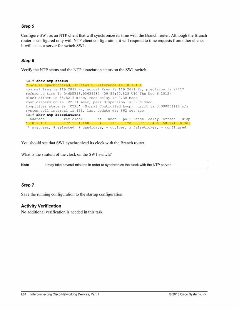
Step 5
Configure SW1 as an NTP client that will synchronize its time with the Branch router. Although the Branchrouter is configured only with NTP client configuration, it will respond to time requests from other clients.It will act as a server for switch SW1.
Step 6
Verify the NTP status and the NTP association status on the SW1 switch.
SW1# show ntp status Clock is synchronized, stratum 5, reference is 10.1.1.1 nominal freq is 119.2092 Hz, actual freq is 119.2091 Hz, precision is 2**17reference time is D46AEB16.D3639982 (09:59:50.825 UTC Thu Dec 6 2012)clock offset is 58.8216 msec, root delay is 2.30 msecroot dispersion is 122.31 msec, peer dispersion is 8.38 msecloopfilter state is 'CTRL' (Normal Controlled Loop), drift is 0.000001118 s/ssystem poll interval is 128, last update was 862 sec ago.SW1# show ntp associations address ref clock st when poll reach delay offset disp*~10.1.1.1 172.16.1.100 4 115 128 377 1.436 58.821 8.389 * sys.peer, # selected, + candidate, - outlyer, x falseticker, ~ configured
You should see that SW1 synchronized its clock with the Branch router.
What is the stratum of the clock on the SW1 switch?
Note It may take several minutes in order to synchronize the clock with the NTP server.
Step 7
Save the running configuration to the startup configuration.
Activity VerificationNo additional verification is needed in this task.
L84 Interconnecting Cisco Networking Devices, Part 1 © 2013 Cisco Systems, Inc.
Lab 3-3: Filtering Traffic withACLs
Activity OverviewObjectivesA common mechanism for filtering traffic is ACLs, which enable you to allow, limit, or restrict access to anetwork resource. In this lab, you will configure traffic filtering using ACLs. After you have completed thisactivity, you will be able to meet these objectives:
Configure extended, named ACLs
Troubleshoot ACLs
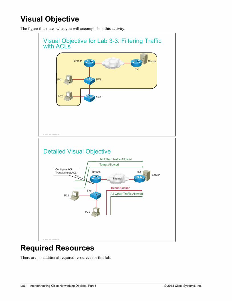
Visual ObjectiveThe figure illustrates what you will accomplish in this activity.
Visual Objective for Lab 3-3: Filtering Trafficwith ACLs
Server
PC1
PC2
SW1
SW2
Branch
HQ
© 2013 Cisco Systems, Inc.
Detailed Visual Objective
Internet
Server
PC1
PC2
SW1
QHhcnarBConfigure ACL
Troubleshoot ACL
Telnet Allowed
Telnet Blocked
All Other Traffic Allowed
All Other Traffic Allowed
© 2013 Cisco Systems, Inc.
Required ResourcesThere are no additional required resources for this lab.
L86 Interconnecting Cisco Networking Devices, Part 1 © 2013 Cisco Systems, Inc.
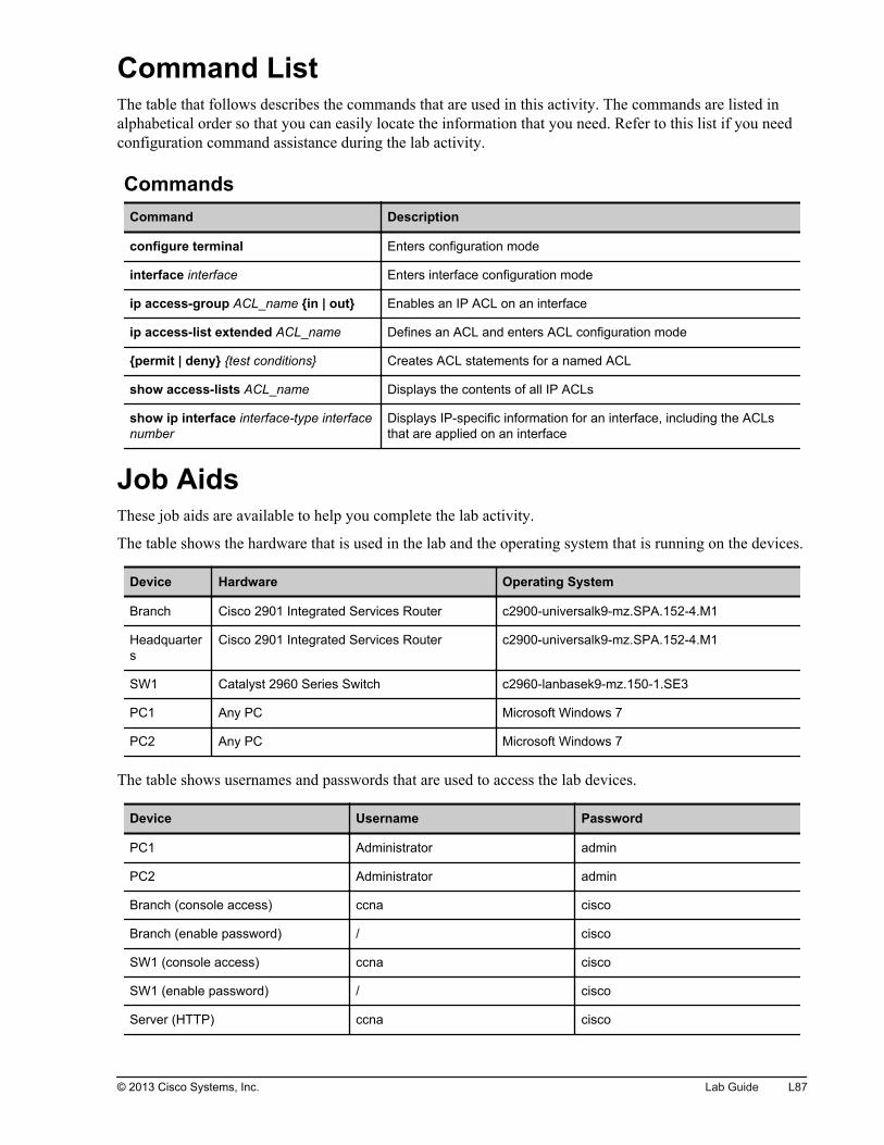
Command ListThe table that follows describes the commands that are used in this activity. The commands are listed inalphabetical order so that you can easily locate the information that you need. Refer to this list if you needconfiguration command assistance during the lab activity.
CommandsCommand Description
configure terminal Enters configuration mode
interface interface Enters interface configuration mode
ip access-group ACL_name {in | out} Enables an IP ACL on an interface
ip access-list extended ACL_name Defines an ACL and enters ACL configuration mode
{permit | deny} {test conditions} Creates ACL statements for a named ACL
show access-lists ACL_name Displays the contents of all IP ACLs
show ip interface interface-type interfacenumber
Displays IP-specific information for an interface, including the ACLsthat are applied on an interface
Job AidsThese job aids are available to help you complete the lab activity.
The table shows the hardware that is used in the lab and the operating system that is running on the devices.
Device Hardware Operating System
Branch Cisco 2901 Integrated Services Router c2900-universalk9-mz.SPA.152-4.M1
Headquarters
Cisco 2901 Integrated Services Router c2900-universalk9-mz.SPA.152-4.M1
SW1 Catalyst 2960 Series Switch c2960-lanbasek9-mz.150-1.SE3
PC1 Any PC Microsoft Windows 7
PC2 Any PC Microsoft Windows 7
The table shows usernames and passwords that are used to access the lab devices.
Device Username Password
PC1 Administrator admin
PC2 Administrator admin
Branch (console access) ccna cisco
Branch (enable password) / cisco
SW1 (console access) ccna cisco
SW1 (enable password) / cisco
Server (HTTP) ccna cisco
© 2013 Cisco Systems, Inc. Lab Guide L87
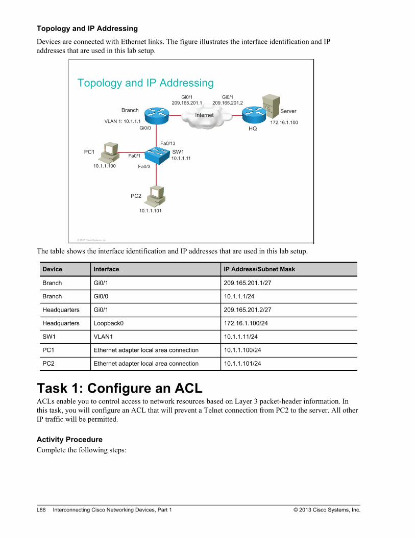
Topology and IP Addressing
Devices are connected with Ethernet links. The figure illustrates the interface identification and IPaddresses that are used in this lab setup.
Topology and IP Addressing
InternetServer
PC1
PC2
SW1
Branch
HQ
Fa0/1
Gi0/0
Fa0/13
Fa0/3
Gi0/1
209.165.201.1
Gi0/1
209.165.201.2
10.1.1.100
10.1.1.101
10.1.1.11
VLAN 1: 10.1.1.1 172.16.1.100
0/3
© 2013 Cisco Systems, Inc.
The table shows the interface identification and IP addresses that are used in this lab setup.
Device Interface IP Address/Subnet Mask
Branch Gi0/1 209.165.201.1/27
Branch Gi0/0 10.1.1.1/24
Headquarters Gi0/1 209.165.201.2/27
Headquarters Loopback0 172.16.1.100/24
SW1 VLAN1 10.1.1.11/24
PC1 Ethernet adapter local area connection 10.1.1.100/24
PC2 Ethernet adapter local area connection 10.1.1.101/24
Task 1: Configure an ACLACLs enable you to control access to network resources based on Layer 3 packet-header information. Inthis task, you will configure an ACL that will prevent a Telnet connection from PC2 to the server. All otherIP traffic will be permitted.
Activity ProcedureComplete the following steps:
L88 Interconnecting Cisco Networking Devices, Part 1 © 2013 Cisco Systems, Inc.
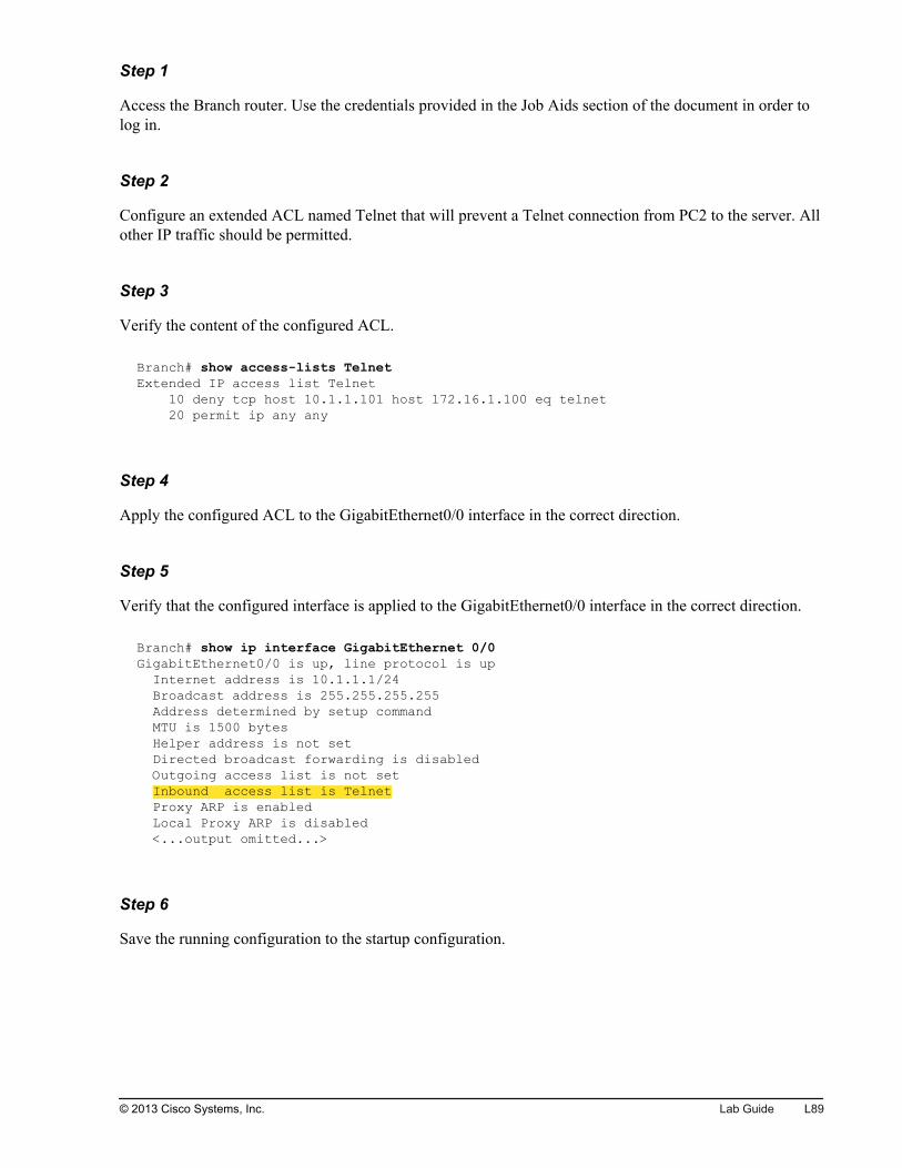
Step 1
Access the Branch router. Use the credentials provided in the Job Aids section of the document in order tolog in.
Step 2
Configure an extended ACL named Telnet that will prevent a Telnet connection from PC2 to the server. Allother IP traffic should be permitted.
Step 3
Verify the content of the configured ACL.
Branch# show access-lists TelnetExtended IP access list Telnet 10 deny tcp host 10.1.1.101 host 172.16.1.100 eq telnet 20 permit ip any any
Step 4
Apply the configured ACL to the GigabitEthernet0/0 interface in the correct direction.
Step 5
Verify that the configured interface is applied to the GigabitEthernet0/0 interface in the correct direction.
Branch# show ip interface GigabitEthernet 0/0GigabitEthernet0/0 is up, line protocol is up Internet address is 10.1.1.1/24 Broadcast address is 255.255.255.255 Address determined by setup command MTU is 1500 bytes Helper address is not set Directed broadcast forwarding is disabled Outgoing access list is not set Inbound access list is Telnet Proxy ARP is enabled Local Proxy ARP is disabled <...output omitted...>
Step 6
Save the running configuration to the startup configuration.
© 2013 Cisco Systems, Inc. Lab Guide L89

Step 7
Access PC1. Open PuTTY by double-clicking the PuTTY icon and establish a Telnet session to the serverat 172.16.1.100.
L90 Interconnecting Cisco Networking Devices, Part 1 © 2013 Cisco Systems, Inc.
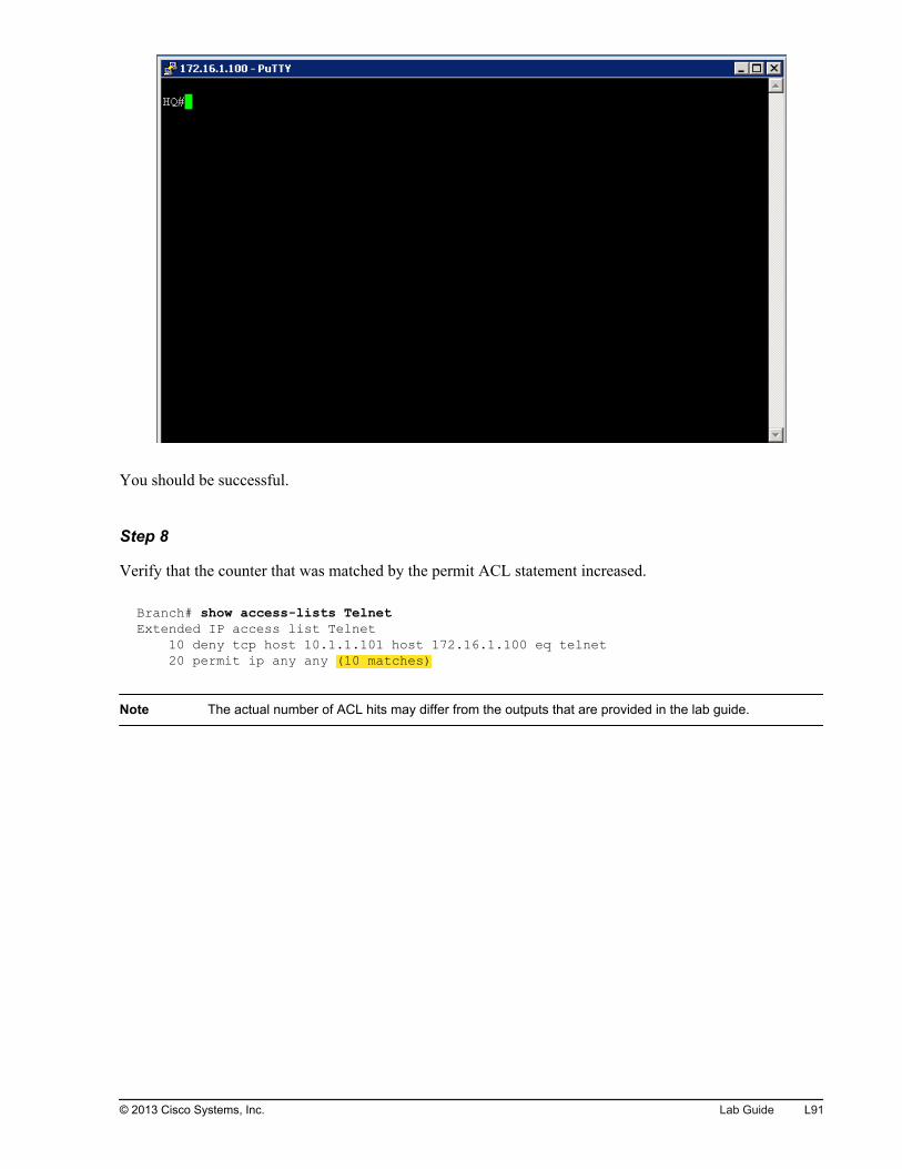
You should be successful.
Step 8
Verify that the counter that was matched by the permit ACL statement increased.
Branch# show access-lists TelnetExtended IP access list Telnet 10 deny tcp host 10.1.1.101 host 172.16.1.100 eq telnet 20 permit ip any any (10 matches)
Note The actual number of ACL hits may differ from the outputs that are provided in the lab guide.
© 2013 Cisco Systems, Inc. Lab Guide L91
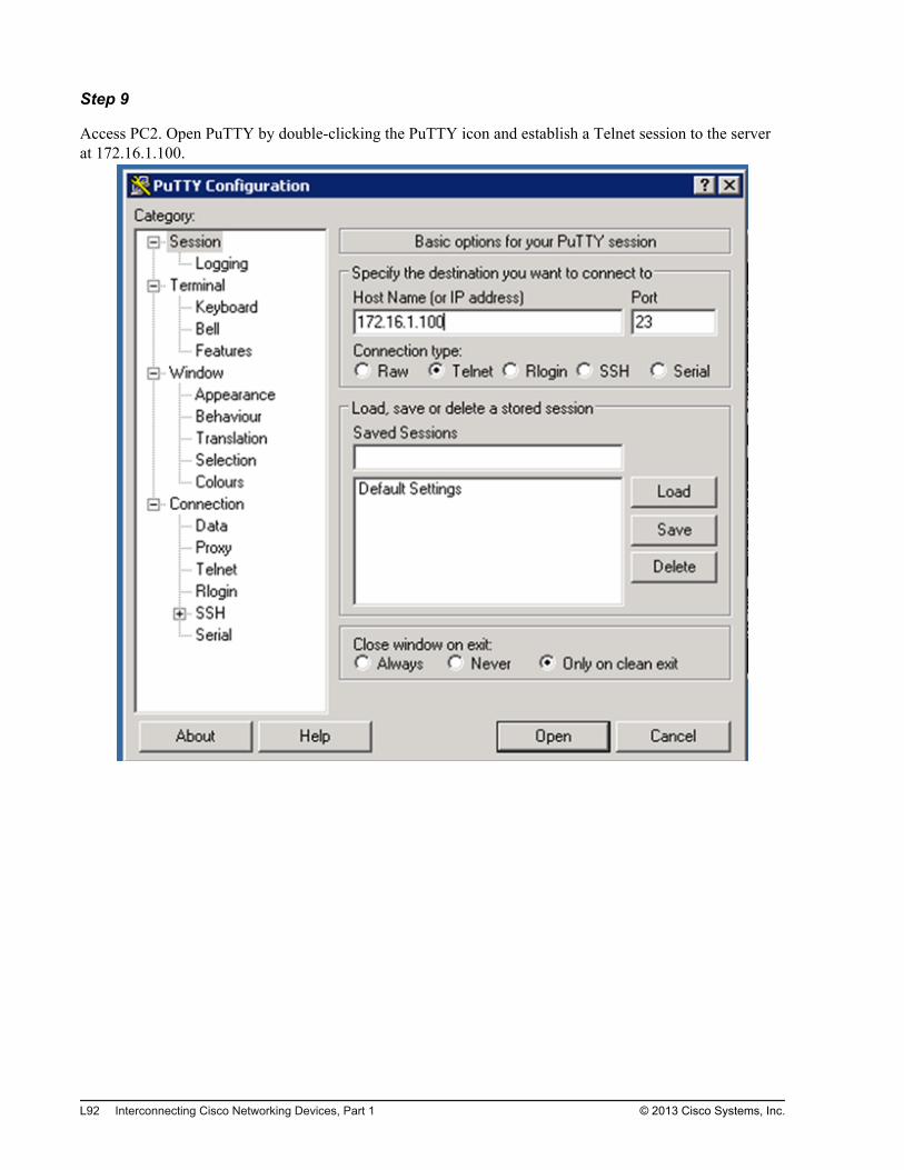
Step 9
Access PC2. Open PuTTY by double-clicking the PuTTY icon and establish a Telnet session to the serverat 172.16.1.100.
L92 Interconnecting Cisco Networking Devices, Part 1 © 2013 Cisco Systems, Inc.
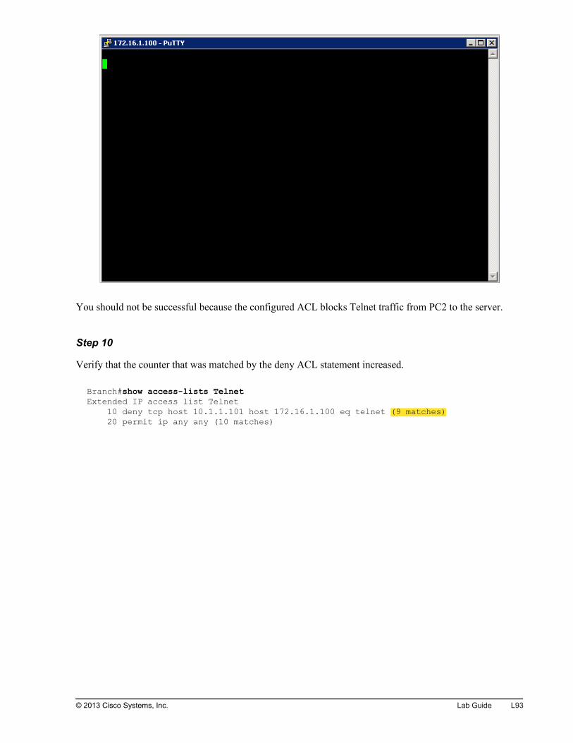
You should not be successful because the configured ACL blocks Telnet traffic from PC2 to the server.
Step 10
Verify that the counter that was matched by the deny ACL statement increased.
Branch#show access-lists TelnetExtended IP access list Telnet 10 deny tcp host 10.1.1.101 host 172.16.1.100 eq telnet (9 matches) 20 permit ip any any (10 matches)
© 2013 Cisco Systems, Inc. Lab Guide L93

Step 11
Access PC1. Open Internet Explorer and try to reach the HTTP server at IP address 172.16.1.100. Use thecredentials that are provided in the Job Aids section of the document in order to log in.
You should be successful.
L94 Interconnecting Cisco Networking Devices, Part 1 © 2013 Cisco Systems, Inc.
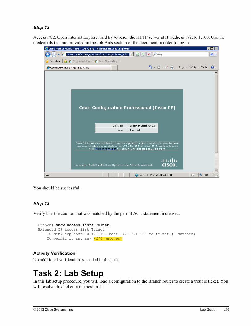
Step 12
Access PC2. Open Internet Explorer and try to reach the HTTP server at IP address 172.16.1.100. Use thecredentials that are provided in the Job Aids section of the document in order to log in.
You should be successful.
Step 13
Verify that the counter that was matched by the permit ACL statement increased.
Branch# show access-lists TelnetExtended IP access list Telnet 10 deny tcp host 10.1.1.101 host 172.16.1.100 eq telnet (9 matches) 20 permit ip any any (274 matches)
Activity VerificationNo additional verification is needed in this task.
Task 2: Lab SetupIn this lab setup procedure, you will load a configuration to the Branch router to create a trouble ticket. Youwill resolve this ticket in the next task.
© 2013 Cisco Systems, Inc. Lab Guide L95
Activity ProcedureComplete the following steps:
Step 1
Access the Branch router.
Step 2
Copy the TSHOOT_Troubleshoot_ACLs_Branch.cfg file from the router flash memory into the routerrunning configuration.
Branch# copy flash:TSHOOT_Troubleshoot_ACLs_Branch.cfg running-config3341 bytes copied in 3.490 secs (957 bytes/sec)
Activity VerificationNo additional verification is needed in this task.
Task 3: Troubleshoot an ACLIt is very important to be able to analyze the behavior of configured ACLs and to troubleshoot them. In thistask, you will troubleshoot the previously loaded trouble ticket. You should change the configuration so thata Telnet connection from PC2 to the server is not permitted, while all other IP traffic to the server isallowed.
Activity ProcedureComplete the following steps:
L96 Interconnecting Cisco Networking Devices, Part 1 © 2013 Cisco Systems, Inc.
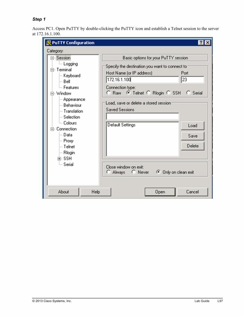
Step 1
Access PC1. Open PuTTY by double-clicking the PuTTY icon and establish a Telnet session to the serverat 172.16.1.100.
© 2013 Cisco Systems, Inc. Lab Guide L97

You should be successful.
L98 Interconnecting Cisco Networking Devices, Part 1 © 2013 Cisco Systems, Inc.
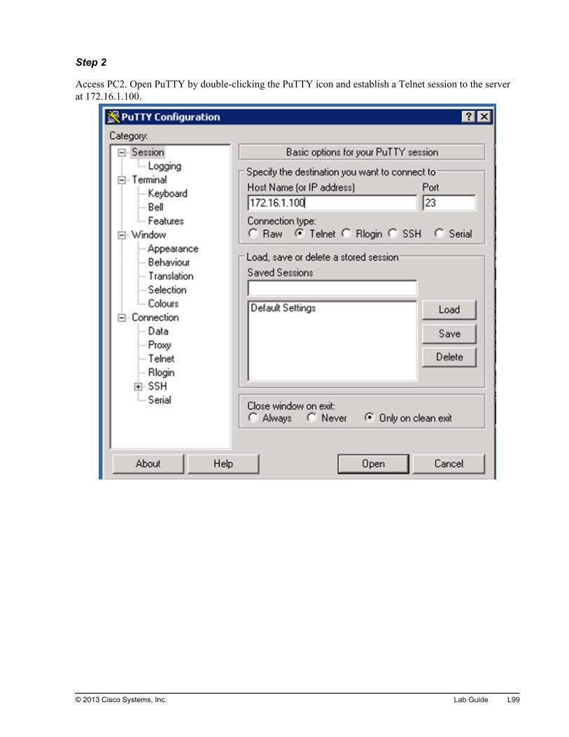
Step 2
Access PC2. Open PuTTY by double-clicking the PuTTY icon and establish a Telnet session to the serverat 172.16.1.100.
© 2013 Cisco Systems, Inc. Lab Guide L99
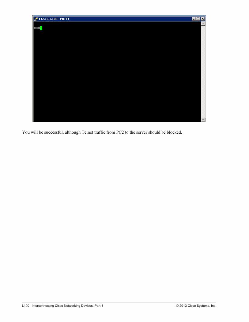
You will be successful, although Telnet traffic from PC2 to the server should be blocked.
L100 Interconnecting Cisco Networking Devices, Part 1 © 2013 Cisco Systems, Inc.
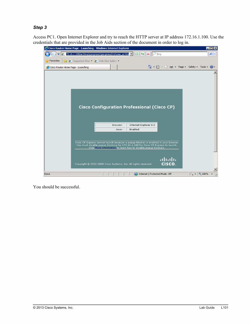
Step 3
Access PC1. Open Internet Explorer and try to reach the HTTP server at IP address 172.16.1.100. Use thecredentials that are provided in the Job Aids section of the document in order to log in.
You should be successful.
© 2013 Cisco Systems, Inc. Lab Guide L101
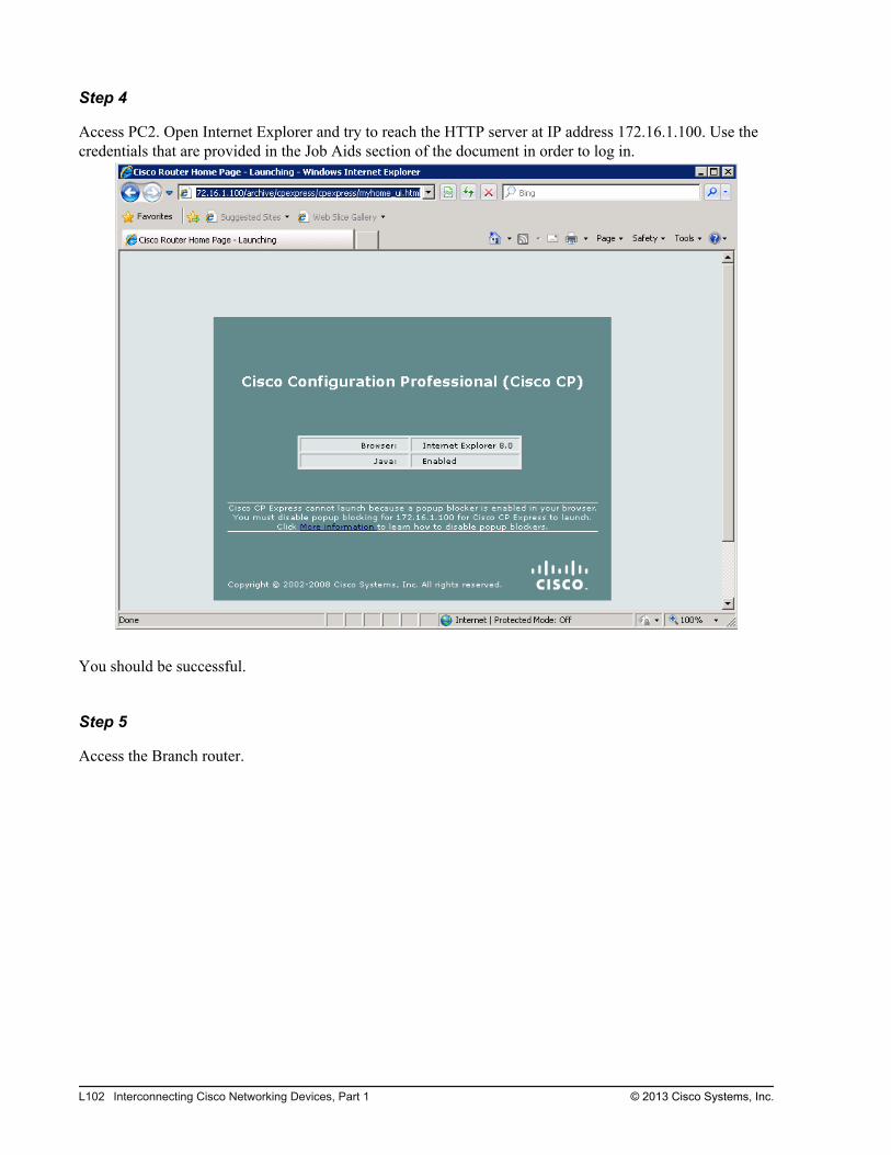
Step 4
Access PC2. Open Internet Explorer and try to reach the HTTP server at IP address 172.16.1.100. Use thecredentials that are provided in the Job Aids section of the document in order to log in.
You should be successful.
Step 5
Access the Branch router.
L102 Interconnecting Cisco Networking Devices, Part 1 © 2013 Cisco Systems, Inc.

Step 6
Verify that the configured ACL is applied to the GigabitEthernet0/0 interface in the correct direction.
Branch# show ip interface GigabitEthernet 0/0GigabitEthernet0/0 is up, line protocol is up Internet address is 10.1.1.1/24 Broadcast address is 255.255.255.255 Address determined by setup command MTU is 1500 bytes Helper address is not set Directed broadcast forwarding is disabled Outgoing access list is Telnet Inbound access list is not set Proxy ARP is enabled Local Proxy ARP is disabled <...output omitted...>
Step 7
Apply the configured ACL to the GigabitEthernet0/0 interface in the correct direction.
Step 8
Verify the contents of the configured ACL.
Branch# show access-lists TelnetExtended IP access list Telnet 10 permit ip any any (338 matches) 20 deny ip any any 30 deny tcp host 10.1.1.101 host 172.16.1.100 eq telnet
Step 9
Change the Telnet ACL so that it prevents Telnet connections from PC2 to the server. All other IP trafficshould be permitted.
Step 10
Save the running configuration to the startup configuration.
© 2013 Cisco Systems, Inc. Lab Guide L103

Step 11
Access PC1. Open PuTTY by double-clicking the PuTTY icon and establish a Telnet session to the serverat 172.16.1.100.
L104 Interconnecting Cisco Networking Devices, Part 1 © 2013 Cisco Systems, Inc.
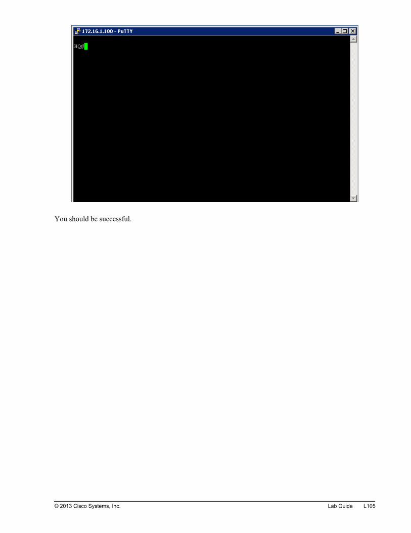
You should be successful.
© 2013 Cisco Systems, Inc. Lab Guide L105

Step 12
Access PC2. Open PuTTY by double-clicking the PuTTY icon and establish a Telnet session to the serverat 172.16.1.100.
L106 Interconnecting Cisco Networking Devices, Part 1 © 2013 Cisco Systems, Inc.
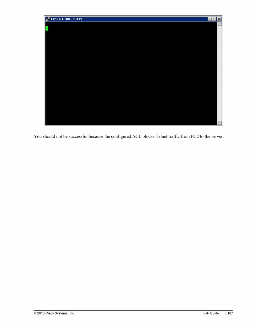
You should not be successful because the configured ACL blocks Telnet traffic from PC2 to the server.
© 2013 Cisco Systems, Inc. Lab Guide L107
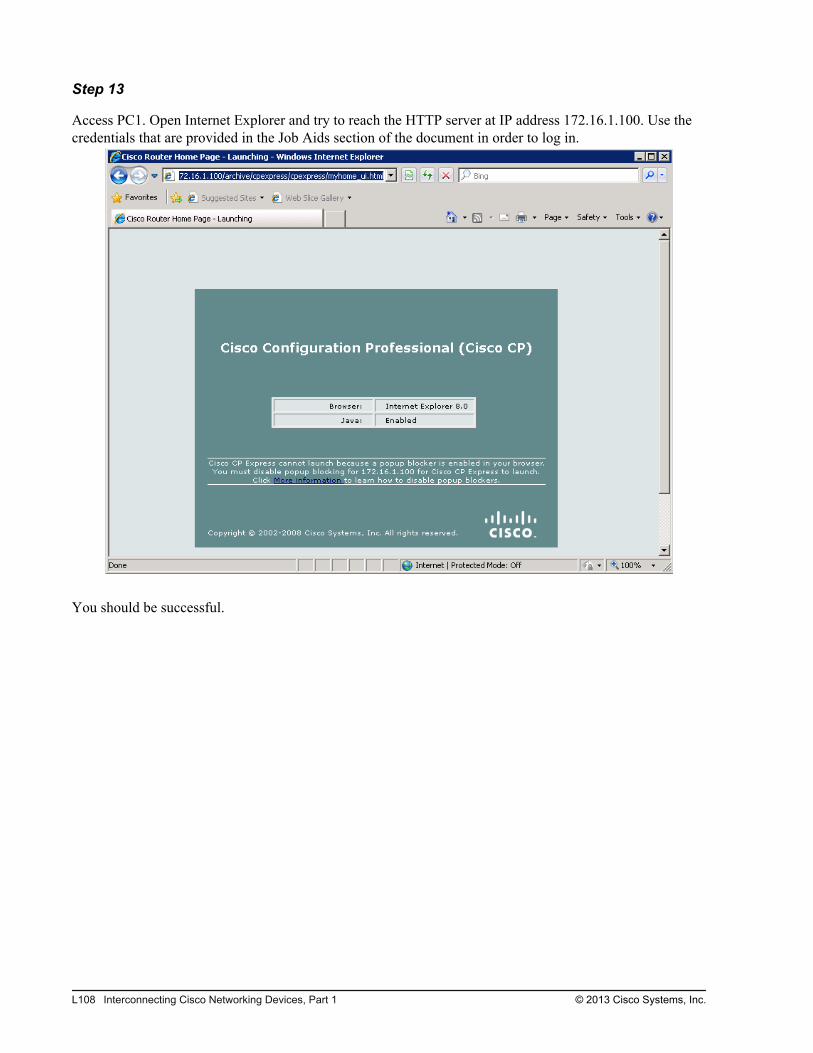
Step 13
Access PC1. Open Internet Explorer and try to reach the HTTP server at IP address 172.16.1.100. Use thecredentials that are provided in the Job Aids section of the document in order to log in.
You should be successful.
L108 Interconnecting Cisco Networking Devices, Part 1 © 2013 Cisco Systems, Inc.

Step 14
Access PC2. Open Internet Explorer and try to reach the HTTP server at IP address 172.16.1.100. Use thecredentials that are provided in the Job Aids section of the document in order to log in.
You should be successful.
Activity VerificationNo additional verification is needed in this task.
© 2013 Cisco Systems, Inc. Lab Guide L109

L110 Interconnecting Cisco Networking Devices, Part 1 © 2013 Cisco Systems, Inc.
Lab 4-1: ConfiguringExpanded SwitchedNetworks
Activity OverviewObjectivesIn this lab, you will configure two switches to meet specified VLAN requirements. After completing thisactivity, you will be able to meet these objectives:
Configure VLANs
Configure trunking
Configure router with a trunk link
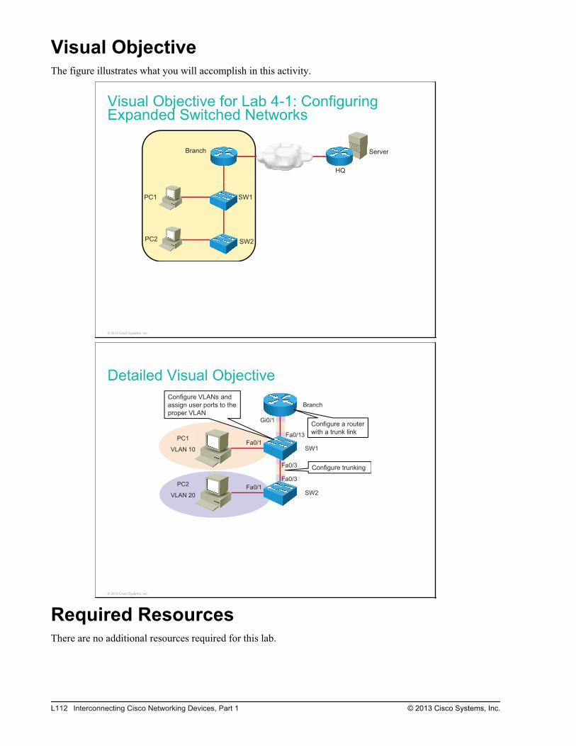
Visual ObjectiveThe figure illustrates what you will accomplish in this activity.
Visual Objective for Lab 4-1: ConfiguringExpanded Switched Networks
Server
PC1
PC2
SW1
SW2
Branch
HQ
© 2013 Cisco Systems, Inc.
Detailed Visual Objective
Branch
PC1
VLAN 10
Configure VLANs and
assign user ports to the
proper VLAN
SW1
SW2
Configure trunking
Configure a router
with a trunk link
Fa0/1
Fa0/1
Fa0/3
Fa0/3PC2
VLAN 20
Gi0/1
Fa0/13
© 2013 Cisco Systems, Inc.
Required ResourcesThere are no additional resources required for this lab.
L112 Interconnecting Cisco Networking Devices, Part 1 © 2013 Cisco Systems, Inc.
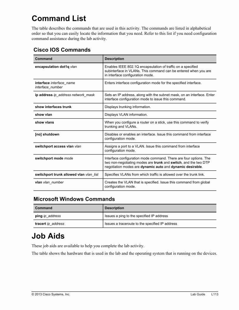
Command ListThe table describes the commands that are used in this activity. The commands are listed in alphabeticalorder so that you can easily locate the information that you need. Refer to this list if you need configurationcommand assistance during the lab activity.
Cisco IOS CommandsCommand Description
encapsulation dot1q vlan Enables IEEE 802.1Q encapsulation of traffic on a specifiedsubinterface in VLANs. This command can be entered when you arein interface configuration mode.
interface interface_nameinterface_number
Enters interface configuration mode for the specified interface.
ip address ip_address network_mask Sets an IP address, along with the subnet mask, on an interface. Enterinterface configuration mode to issue this command.
show interfaces trunk Displays trunking information.
show vlan Displays VLAN information.
show vlans When you configure a router on a stick, use this command to verifytrunking and VLANs.
[no] shutdown Disables or enables an interface. Issue this command from interfaceconfiguration mode.
switchport access vlan vlan Assigns a port to a VLAN. Issue this command from interfaceconfiguration mode.
switchport mode mode Interface configuration mode command. There are four options. Thetwo non-negotiating modes are trunk and switch, and the two DTPnegotiation modes are dynamic auto and dynamic desirable.
switchport trunk allowed vlan vlan_list Specifies VLANs from which traffic is allowed over the trunk link.
vlan vlan_number Creates the VLAN that is specified. Issue this command from globalconfiguration mode.
Microsoft Windows CommandsCommand Description
ping ip_address Issues a ping to the specified IP address
tracert ip_address Issues a traceroute to the specified IP address
Job AidsThese job aids are available to help you complete the lab activity.
The table shows the hardware that is used in the lab and the operating system that is running on the devices.
© 2013 Cisco Systems, Inc. Lab Guide L113
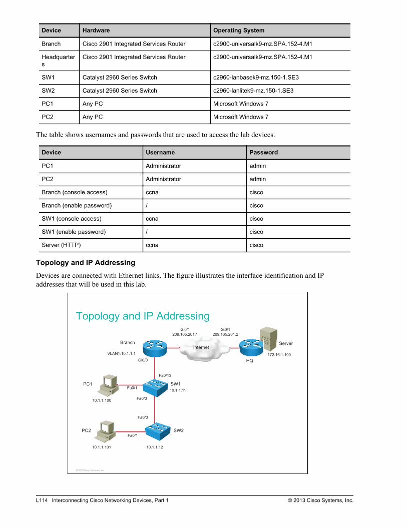
Device Hardware Operating System
Branch Cisco 2901 Integrated Services Router c2900-universalk9-mz.SPA.152-4.M1
Headquarters
Cisco 2901 Integrated Services Router c2900-universalk9-mz.SPA.152-4.M1
SW1 Catalyst 2960 Series Switch c2960-lanbasek9-mz.150-1.SE3
SW2 Catalyst 2960 Series Switch c2960-lanlitek9-mz.150-1.SE3
PC1 Any PC Microsoft Windows 7
PC2 Any PC Microsoft Windows 7
The table shows usernames and passwords that are used to access the lab devices.
Device Username Password
PC1 Administrator admin
PC2 Administrator admin
Branch (console access) ccna cisco
Branch (enable password) / cisco
SW1 (console access) ccna cisco
SW1 (enable password) / cisco
Server (HTTP) ccna cisco
Topology and IP Addressing
Devices are connected with Ethernet links. The figure illustrates the interface identification and IPaddresses that will be used in this lab.
Topology and IP Addressing
InternetServer
PC1
PC2
SW1
Branch
HQ
Fa0/1
Gi0/0
Fa0/13
Fa0/3
Gi0/1
209.165.201.1
Gi0/1
209.165.201.2
10.1.1.100
10.1.1.11
VLAN1:10.1.1.1 172.16.1.100
a0/3
Fa0/3
SW2
Fa0/1
10.1.1.101 10.1.1.12
© 2013 Cisco Systems, Inc.
L114 Interconnecting Cisco Networking Devices, Part 1 © 2013 Cisco Systems, Inc.
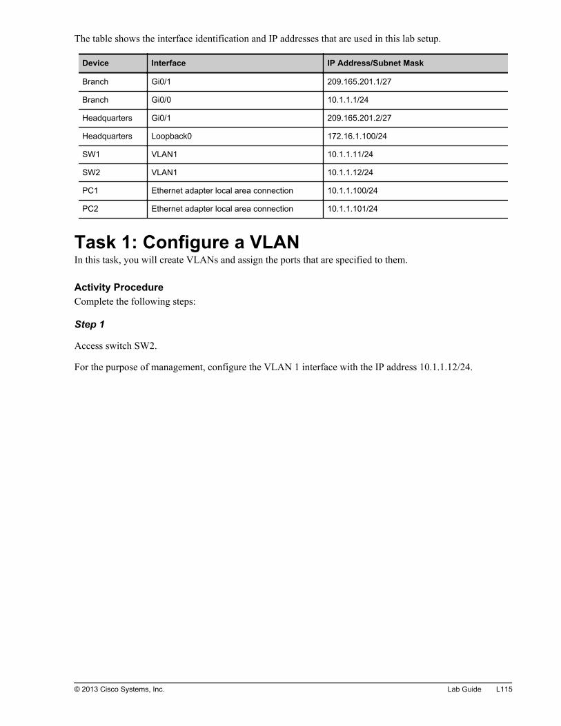
The table shows the interface identification and IP addresses that are used in this lab setup.
Device Interface IP Address/Subnet Mask
Branch Gi0/1 209.165.201.1/27
Branch Gi0/0 10.1.1.1/24
Headquarters Gi0/1 209.165.201.2/27
Headquarters Loopback0 172.16.1.100/24
SW1 VLAN1 10.1.1.11/24
SW2 VLAN1 10.1.1.12/24
PC1 Ethernet adapter local area connection 10.1.1.100/24
PC2 Ethernet adapter local area connection 10.1.1.101/24
Task 1: Configure a VLANIn this task, you will create VLANs and assign the ports that are specified to them.
Activity ProcedureComplete the following steps:
Step 1
Access switch SW2.
For the purpose of management, configure the VLAN 1 interface with the IP address 10.1.1.12/24.
© 2013 Cisco Systems, Inc. Lab Guide L115
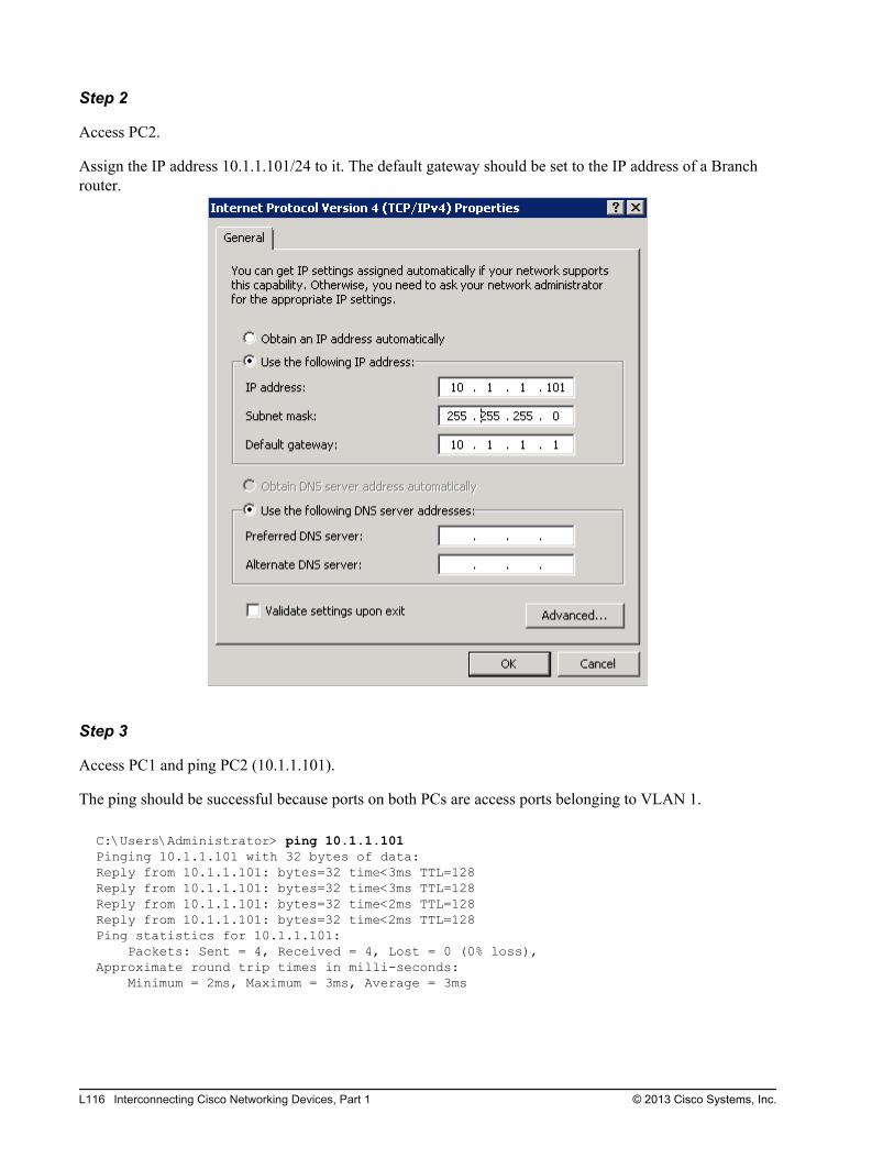
Step 2
Access PC2.
Assign the IP address 10.1.1.101/24 to it. The default gateway should be set to the IP address of a Branchrouter.
Step 3
Access PC1 and ping PC2 (10.1.1.101).
The ping should be successful because ports on both PCs are access ports belonging to VLAN 1.
C:\Users\Administrator> ping 10.1.1.101Pinging 10.1.1.101 with 32 bytes of data:Reply from 10.1.1.101: bytes=32 time<3ms TTL=128Reply from 10.1.1.101: bytes=32 time<3ms TTL=128Reply from 10.1.1.101: bytes=32 time<2ms TTL=128Reply from 10.1.1.101: bytes=32 time<2ms TTL=128Ping statistics for 10.1.1.101: Packets: Sent = 4, Received = 4, Lost = 0 (0% loss), Approximate round trip times in milli-seconds: Minimum = 2ms, Maximum = 3ms, Average = 3ms
L116 Interconnecting Cisco Networking Devices, Part 1 © 2013 Cisco Systems, Inc.
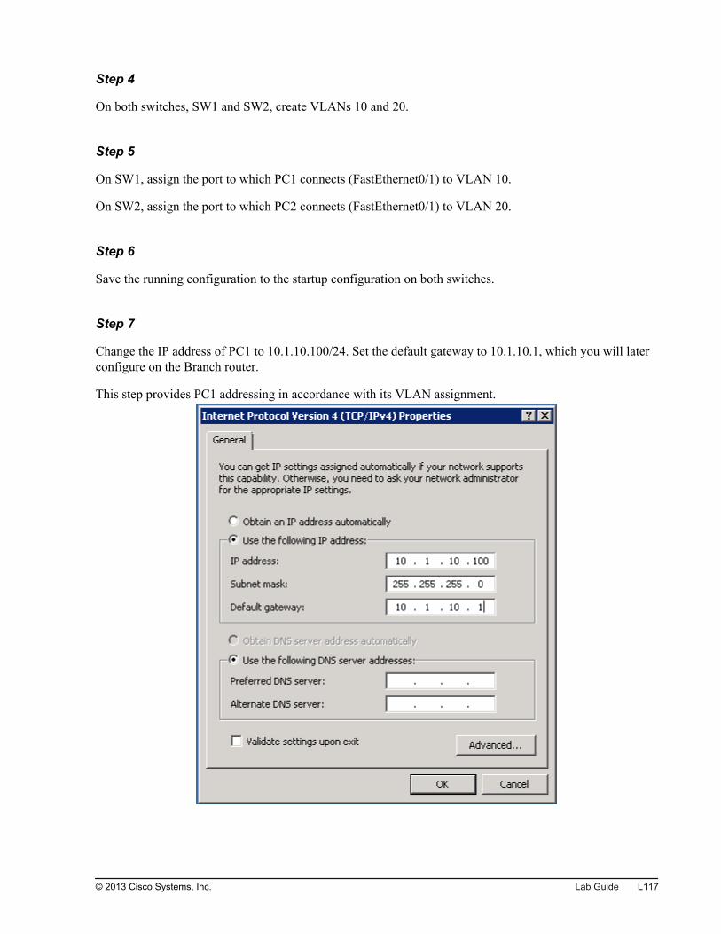
Step 4
On both switches, SW1 and SW2, create VLANs 10 and 20.
Step 5
On SW1, assign the port to which PC1 connects (FastEthernet0/1) to VLAN 10.
On SW2, assign the port to which PC2 connects (FastEthernet0/1) to VLAN 20.
Step 6
Save the running configuration to the startup configuration on both switches.
Step 7
Change the IP address of PC1 to 10.1.10.100/24. Set the default gateway to 10.1.10.1, which you will laterconfigure on the Branch router.
This step provides PC1 addressing in accordance with its VLAN assignment.
© 2013 Cisco Systems, Inc. Lab Guide L117

Step 8
Change the IP address of PC2 to 10.1.20.100/24. Set the default gateway to 10.1.20.1, which you will laterconfigure on the Branch router.
This step provides PC2 addressing in accordance with its VLAN assignment.
Activity VerificationYou have completed this task when you attain these results:
L118 Interconnecting Cisco Networking Devices, Part 1 © 2013 Cisco Systems, Inc.
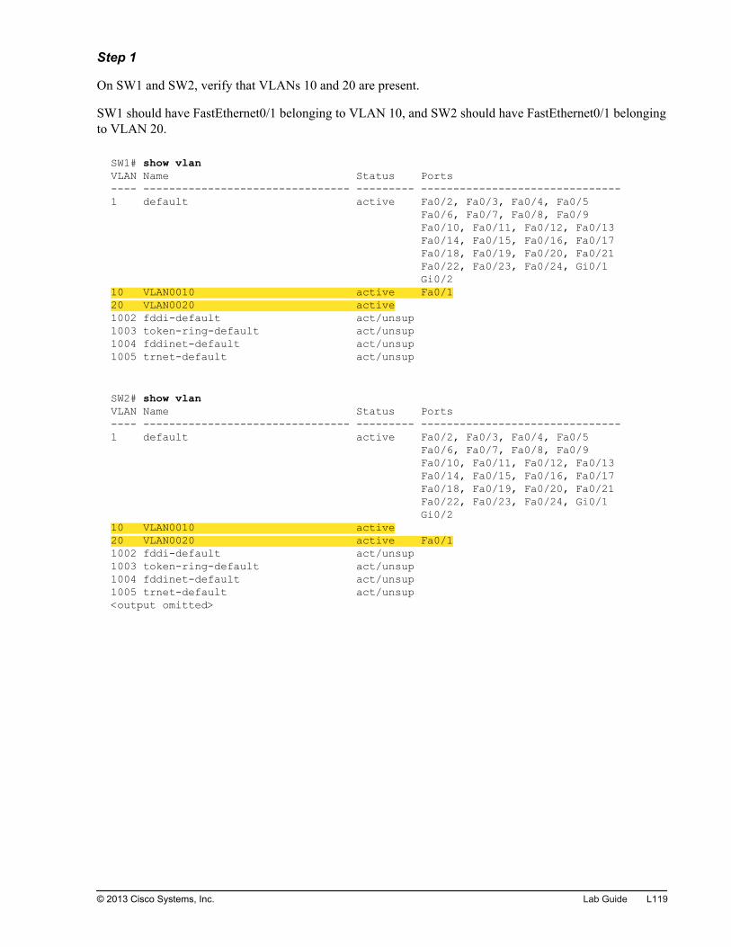
Step 1
On SW1 and SW2, verify that VLANs 10 and 20 are present.
SW1 should have FastEthernet0/1 belonging to VLAN 10, and SW2 should have FastEthernet0/1 belongingto VLAN 20.
SW1# show vlanVLAN Name Status Ports---- -------------------------------- --------- -------------------------------1 default active Fa0/2, Fa0/3, Fa0/4, Fa0/5 Fa0/6, Fa0/7, Fa0/8, Fa0/9 Fa0/10, Fa0/11, Fa0/12, Fa0/13 Fa0/14, Fa0/15, Fa0/16, Fa0/17 Fa0/18, Fa0/19, Fa0/20, Fa0/21 Fa0/22, Fa0/23, Fa0/24, Gi0/1 Gi0/210 VLAN0010 active Fa0/120 VLAN0020 active1002 fddi-default act/unsup1003 token-ring-default act/unsup1004 fddinet-default act/unsup1005 trnet-default act/unsup
SW2# show vlanVLAN Name Status Ports---- -------------------------------- --------- -------------------------------1 default active Fa0/2, Fa0/3, Fa0/4, Fa0/5 Fa0/6, Fa0/7, Fa0/8, Fa0/9 Fa0/10, Fa0/11, Fa0/12, Fa0/13 Fa0/14, Fa0/15, Fa0/16, Fa0/17 Fa0/18, Fa0/19, Fa0/20, Fa0/21 Fa0/22, Fa0/23, Fa0/24, Gi0/1 Gi0/210 VLAN0010 active20 VLAN0020 active Fa0/11002 fddi-default act/unsup1003 token-ring-default act/unsup1004 fddinet-default act/unsup1005 trnet-default act/unsup<output omitted>
© 2013 Cisco Systems, Inc. Lab Guide L119
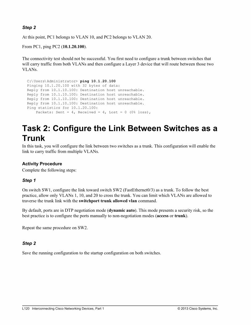
Step 2
At this point, PC1 belongs to VLAN 10, and PC2 belongs to VLAN 20.
From PC1, ping PC2 (10.1.20.100).
The connectivity test should not be successful. You first need to configure a trunk between switches thatwill carry traffic from both VLANs and then configure a Layer 3 device that will route between those twoVLANs.
C:\Users\Administrator> ping 10.1.20.100Pinging 10.1.20.100 with 32 bytes of data:Reply from 10.1.10.100: Destination host unreachable.Reply from 10.1.10.100: Destination host unreachable.Reply from 10.1.10.100: Destination host unreachable.Reply from 10.1.10.100: Destination host unreachable.Ping statistics for 10.1.20.100: Packets: Sent = 4, Received = 4, Lost = 0 (0% loss),
Task 2: Configure the Link Between Switches as aTrunkIn this task, you will configure the link between two switches as a trunk. This configuration will enable thelink to carry traffic from multiple VLANs.
Activity ProcedureComplete the following steps:
Step 1
On switch SW1, configure the link toward switch SW2 (FastEthernet0/3) as a trunk. To follow the bestpractice, allow only VLANs 1, 10, and 20 to cross the trunk. You can limit which VLANs are allowed totraverse the trunk link with the switchport trunk allowed vlan command.
By default, ports are in DTP negotiation mode (dynamic auto). This mode presents a security risk, so thebest practice is to configure the ports manually to non-negotiation modes (access or trunk).
Repeat the same procedure on SW2.
Step 2
Save the running configuration to the startup configuration on both switches.
L120 Interconnecting Cisco Networking Devices, Part 1 © 2013 Cisco Systems, Inc.
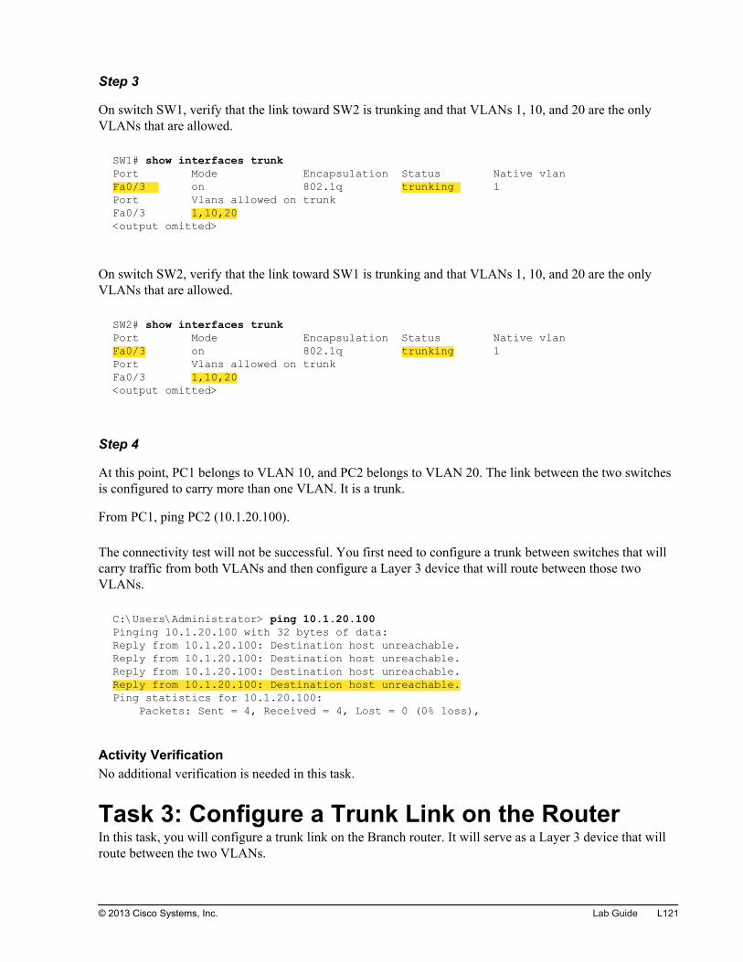
Step 3
On switch SW1, verify that the link toward SW2 is trunking and that VLANs 1, 10, and 20 are the onlyVLANs that are allowed.
SW1# show interfaces trunkPort Mode Encapsulation Status Native vlanFa0/3 on 802.1q trunking 1Port Vlans allowed on trunkFa0/3 1,10,20<output omitted>
On switch SW2, verify that the link toward SW1 is trunking and that VLANs 1, 10, and 20 are the onlyVLANs that are allowed.
SW2# show interfaces trunkPort Mode Encapsulation Status Native vlanFa0/3 on 802.1q trunking 1Port Vlans allowed on trunkFa0/3 1,10,20<output omitted>
Step 4
At this point, PC1 belongs to VLAN 10, and PC2 belongs to VLAN 20. The link between the two switchesis configured to carry more than one VLAN. It is a trunk.
From PC1, ping PC2 (10.1.20.100).
The connectivity test will not be successful. You first need to configure a trunk between switches that willcarry traffic from both VLANs and then configure a Layer 3 device that will route between those twoVLANs.
C:\Users\Administrator> ping 10.1.20.100Pinging 10.1.20.100 with 32 bytes of data:Reply from 10.1.20.100: Destination host unreachable.Reply from 10.1.20.100: Destination host unreachable.Reply from 10.1.20.100: Destination host unreachable.Reply from 10.1.20.100: Destination host unreachable.Ping statistics for 10.1.20.100: Packets: Sent = 4, Received = 4, Lost = 0 (0% loss),
Activity VerificationNo additional verification is needed in this task.
Task 3: Configure a Trunk Link on the RouterIn this task, you will configure a trunk link on the Branch router. It will serve as a Layer 3 device that willroute between the two VLANs.
© 2013 Cisco Systems, Inc. Lab Guide L121
Activity ProcedureComplete the following steps:
Step 1
On switch SW1, configure the link toward the Branch router (FastEthernet0/13) as a trunk.
Step 2
Save the running configuration to the startup configuration on the SW1 switch.
Step 3
On the Branch router, remove the IP address from the GigabitEthernet0/0 interface.
Step 4
On the Branch router, configure three subinterfaces. Subinterface GigabitEthernet0/0.1 should have an IPaddress of 10.1.1.1/24 and belong to VLAN 1. Subinterface GigabitEthernet0/0.10 should have an IPaddress of 10.1.10.1/24 and belong to VLAN 10. Subinterface GigabitEthernet0/0.20 should have an IPaddress of 10.1.20.1/24 and belong to VLAN 20.
Step 5
Save the running configuration to the startup configuration on the Branch router.
L122 Interconnecting Cisco Networking Devices, Part 1 © 2013 Cisco Systems, Inc.
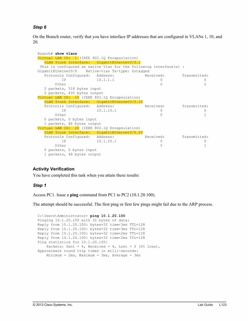
Step 6
On the Branch router, verify that you have interface IP addresses that are configured in VLANs 1, 10, and20.
Branch# show vlans Virtual LAN ID: 1 (IEEE 802.1Q Encapsulation) vLAN Trunk Interface: GigabitEthernet0/0.1 This is configured as native Vlan for the following interface(s) :GigabitEthernet0/0 Native-vlan Tx-type: Untagged Protocols Configured: Address: Received: Transmitted: IP 10.1.1.1 0 0 Other 0 2 2 packets, 518 bytes input 2 packets, 435 bytes outputVirtual LAN ID: 10 (IEEE 802.1Q Encapsulation) vLAN Trunk Interface: GigabitEthernet0/0.10 Protocols Configured: Address: Received: Transmitted: IP 10.1.10.1 0 0 Other 0 1 0 packets, 0 bytes input 1 packets, 46 bytes outputVirtual LAN ID: 20 (IEEE 802.1Q Encapsulation) vLAN Trunk Interface: GigabitEthernet0/0.20 Protocols Configured: Address: Received: Transmitted: IP 10.1.20.1 0 0 Other 0 1 0 packets, 0 bytes input 1 packets, 46 bytes output
Activity VerificationYou have completed this task when you attain these results:
Step 1
Access PC1. Issue a ping command from PC1 to PC2 (10.1.20.100).
The attempt should be successful. The first ping or first few pings might fail due to the ARP process.
C:\Users\Administrator> ping 10.1.20.100Pinging 10.1.20.100 with 32 bytes of data:Reply from 10.1.20.100: bytes=32 time<3ms TTL=128Reply from 10.1.20.100: bytes=32 time<3ms TTL=128Reply from 10.1.20.100: bytes=32 time<2ms TTL=128Reply from 10.1.20.100: bytes=32 time<2ms TTL=128Ping statistics for 10.1.20.100: Packets: Sent = 4, Received = 4, Lost = 0 (0% loss), Approximate round trip times in milli-seconds: Minimum = 2ms, Maximum = 3ms, Average = 3ms
© 2013 Cisco Systems, Inc. Lab Guide L123

Step 2
From PC1, use the traceroute (tracert command) utility to trace the path from PC1 to PC2.
Notice that the traffic goes through the Branch router.
C:\Users\Administrator> tracert 10.1.20.100Tracing route to 10.1.20.100 over a maximum of 30 hops 1 4 ms 1 ms 1 ms 10.1.10.1 2 2 ms 1 ms 1 ms 10.1.20.100Trace complete.
L124 Interconnecting Cisco Networking Devices, Part 1 © 2013 Cisco Systems, Inc.
Lab 4-2: Configuring DHCPServer
Activity OverviewObjectivesIn this lab, you will assign IP addresses to network devices using DHCP. After completing this activity, youwill be able to meet these objectives:
Configure a DHCP server
Exclude specific IP addresses from DHCP pools
Configure a DHCP relay agent
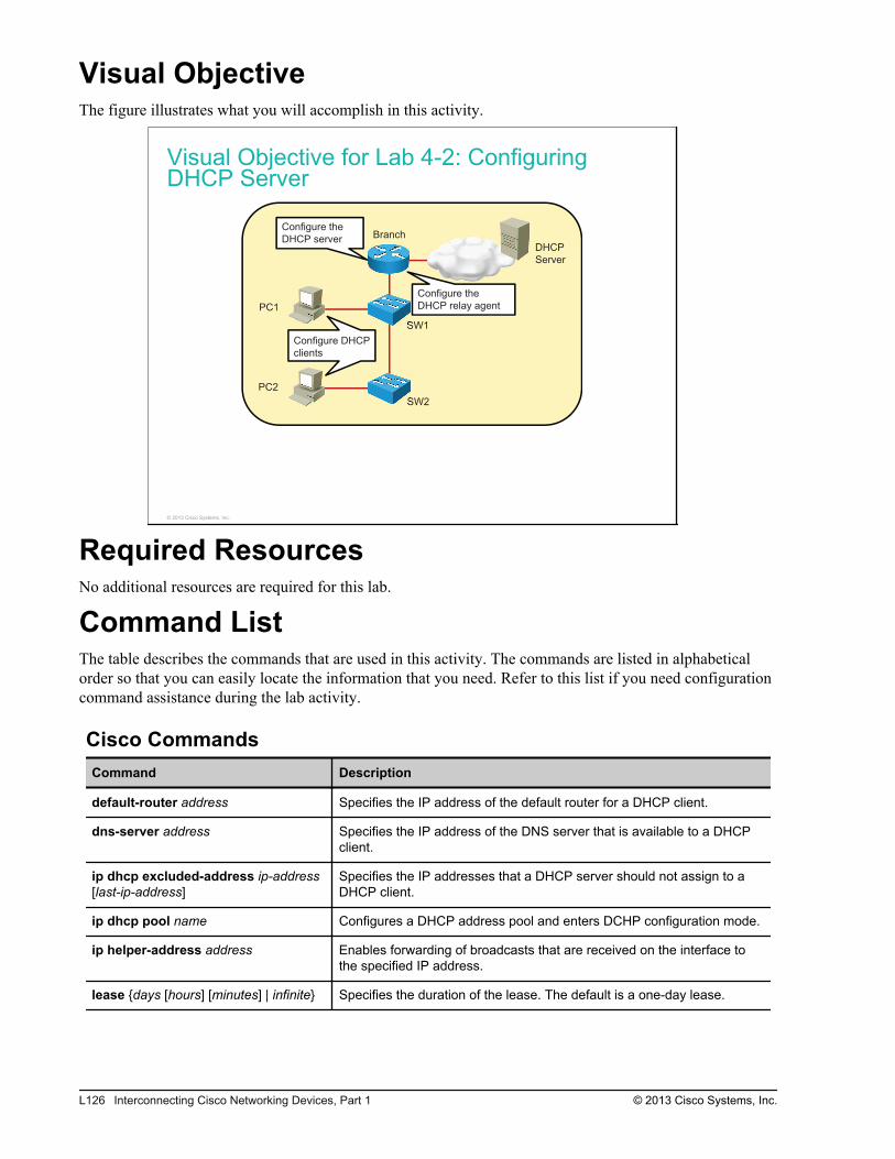
Visual ObjectiveThe figure illustrates what you will accomplish in this activity.
Visual Objective for Lab 4-2: ConfiguringDHCP Server
DHCP
Server
PC1
PC2
SW1
SW2
BranchConfigure the
DHCP server
Configure the
DHCP relay agent
Configure DHCP
clients
© 2013 Cisco Systems, Inc.
Required ResourcesNo additional resources are required for this lab.
Command ListThe table describes the commands that are used in this activity. The commands are listed in alphabeticalorder so that you can easily locate the information that you need. Refer to this list if you need configurationcommand assistance during the lab activity.
Cisco CommandsCommand Description
default-router address Specifies the IP address of the default router for a DHCP client.
dns-server address Specifies the IP address of the DNS server that is available to a DHCPclient.
ip dhcp excluded-address ip-address[last-ip-address]
Specifies the IP addresses that a DHCP server should not assign to aDHCP client.
ip dhcp pool name Configures a DHCP address pool and enters DCHP configuration mode.
ip helper-address address Enables forwarding of broadcasts that are received on the interface tothe specified IP address.
lease {days [hours] [minutes] | infinite} Specifies the duration of the lease. The default is a one-day lease.
L126 Interconnecting Cisco Networking Devices, Part 1 © 2013 Cisco Systems, Inc.
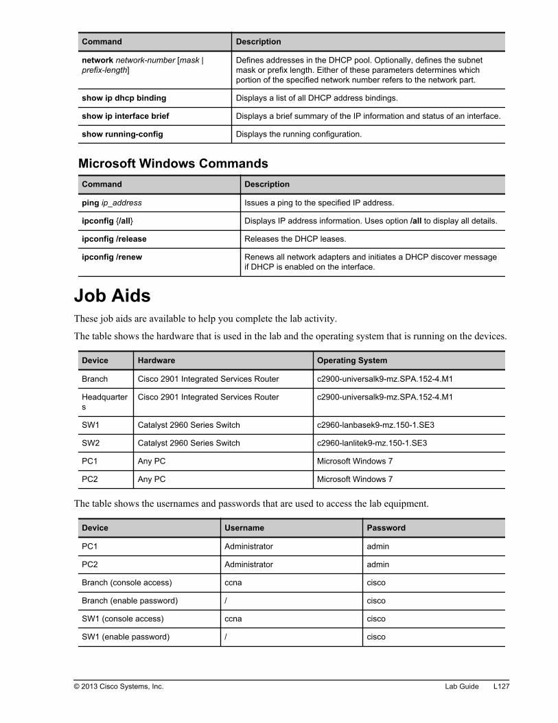
Command Description
network network-number [mask |prefix-length]
Defines addresses in the DHCP pool. Optionally, defines the subnetmask or prefix length. Either of these parameters determines whichportion of the specified network number refers to the network part.
show ip dhcp binding Displays a list of all DHCP address bindings.
show ip interface brief Displays a brief summary of the IP information and status of an interface.
show running-config Displays the running configuration.
Microsoft Windows CommandsCommand Description
ping ip_address Issues a ping to the specified IP address.
ipconfig {/all} Displays IP address information. Uses option /all to display all details.
ipconfig /release Releases the DHCP leases.
ipconfig /renew Renews all network adapters and initiates a DHCP discover messageif DHCP is enabled on the interface.
Job AidsThese job aids are available to help you complete the lab activity.
The table shows the hardware that is used in the lab and the operating system that is running on the devices.
Device Hardware Operating System
Branch Cisco 2901 Integrated Services Router c2900-universalk9-mz.SPA.152-4.M1
Headquarters
Cisco 2901 Integrated Services Router c2900-universalk9-mz.SPA.152-4.M1
SW1 Catalyst 2960 Series Switch c2960-lanbasek9-mz.150-1.SE3
SW2 Catalyst 2960 Series Switch c2960-lanlitek9-mz.150-1.SE3
PC1 Any PC Microsoft Windows 7
PC2 Any PC Microsoft Windows 7
The table shows the usernames and passwords that are used to access the lab equipment.
Device Username Password
PC1 Administrator admin
PC2 Administrator admin
Branch (console access) ccna cisco
Branch (enable password) / cisco
SW1 (console access) ccna cisco
SW1 (enable password) / cisco
© 2013 Cisco Systems, Inc. Lab Guide L127

Topology and IP Addressing
Devices are connected with Ethernet links. The figure illustrates the interface identification and IPaddresses that are used in this lab setup.
Topology and IP Addressing
SW2
10.1.1.12
DHCP
Server
PC1
PC2
SW1
Branch
HQ
Fa0/1
Fa0/13
Fa0/3
Gi0/1
209.165.201.1
Gi0/1
209.165.201.2
10.1.10.100
10.1.20.100
10.1.1.11
Gi0/0—VLAN 1:10.1.1.1
Gi0/0.10—VLAN 10: 10.1.10.1
Gi0/0.20—VLAN 20: 10.1.20.1 172.16.1.100
Fa0/1
Fa0/3
© 2013 Cisco Systems, Inc.
The table shows the interface identification and IP addresses that are used in this lab setup.
Device Interface IP Address/Subnet Mask
Branch Gi0/1 209.165.201.1/27
Branch Gi0/0.1 10.1.1.1/24
Branch Gi0/0.10 10.1.10.1/24
Branch Gi0/0.20 10.1.20.1/24
HQ Gi0/1 209.165.201.2/27
HQ Loopback0 172.16.1.100/24
SW1 VLAN1 10.1.1.11/24
SW2 VLAN1 10.1.1.12/24
PC1 Ethernet adapter local area connection 10.1.10.100/24
PC2 Ethernet adapter local area connection 10.1.20.100/24
VLAN Setup
Three VLANs are configured on the switches. VLAN 1 is used for switch management, VLAN 10 is usedto connect PC1, and VLAN 20 is used to connect PC2. A trunk is enabled between the switches andbetween the SW1 switch and the Branch router. The figure illustrates the trunk and VLAN setup.
L128 Interconnecting Cisco Networking Devices, Part 1 © 2013 Cisco Systems, Inc.
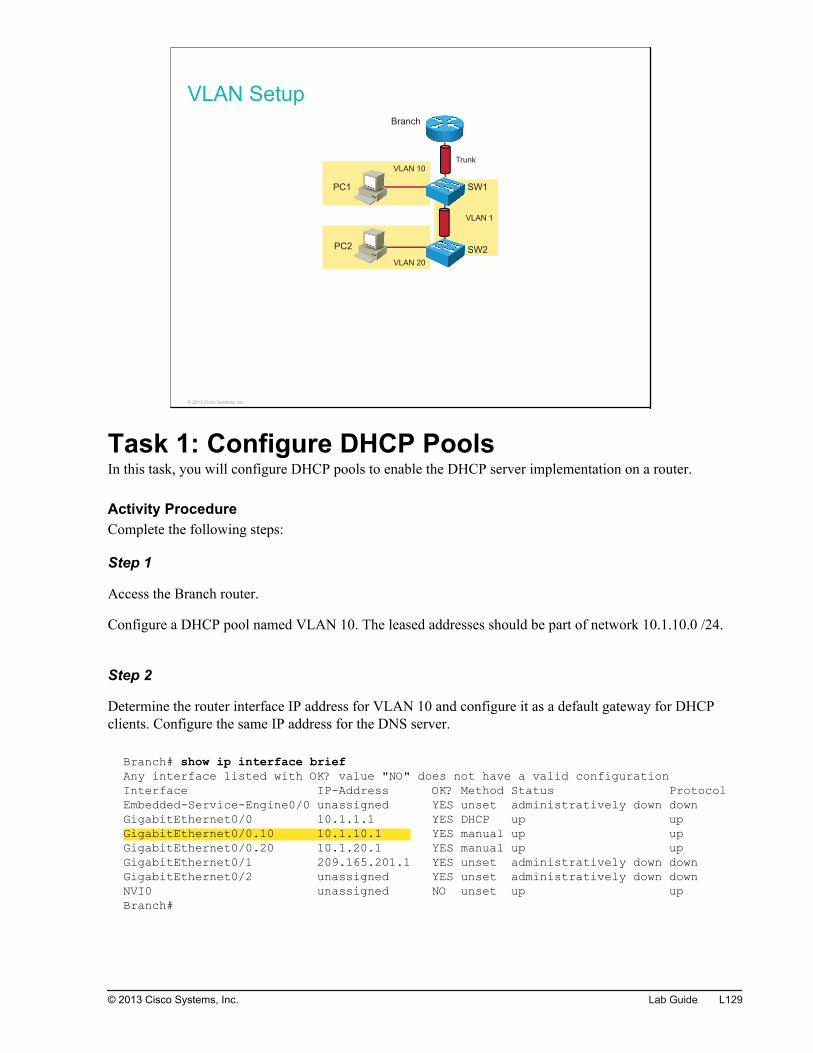
VLAN Setup
VLAN 1
VLAN 10
VLAN 20
PC1
PC2
SW1
SW2
Branch
Trunk
© 2013 Cisco Systems, Inc.
Task 1: Configure DHCP PoolsIn this task, you will configure DHCP pools to enable the DHCP server implementation on a router.
Activity ProcedureComplete the following steps:
Step 1
Access the Branch router.
Configure a DHCP pool named VLAN 10. The leased addresses should be part of network 10.1.10.0 /24.
Step 2
Determine the router interface IP address for VLAN 10 and configure it as a default gateway for DHCPclients. Configure the same IP address for the DNS server.
Branch# show ip interface briefAny interface listed with OK? value "NO" does not have a valid configurationInterface IP-Address OK? Method Status ProtocolEmbedded-Service-Engine0/0 unassigned YES unset administratively down downGigabitEthernet0/0 10.1.1.1 YES DHCP up upGigabitEthernet0/0.10 10.1.10.1 YES manual up upGigabitEthernet0/0.20 10.1.20.1 YES manual up upGigabitEthernet0/1 209.165.201.1 YES unset administratively down downGigabitEthernet0/2 unassigned YES unset administratively down downNVI0 unassigned NO unset up upBranch#
© 2013 Cisco Systems, Inc. Lab Guide L129
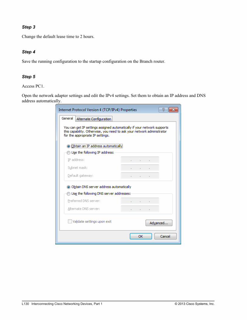
Step 3
Change the default lease time to 2 hours.
Step 4
Save the running configuration to the startup configuration on the Branch router.
Step 5
Access PC1.
Open the network adapter settings and edit the IPv4 settings. Set them to obtain an IP address and DNSaddress automatically.
L130 Interconnecting Cisco Networking Devices, Part 1 © 2013 Cisco Systems, Inc.
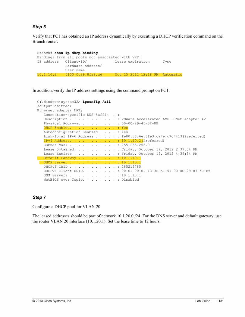
Step 6
Verify that PC1 has obtained an IP address dynamically by executing a DHCP verification command on theBranch router.
Branch# show ip dhcp bindingBindings from all pools not associated with VRF:IP address Client-ID/ Lease expiration Type Hardware address/ User name10.1.10.2 0100.0c29.8fa8.a6 Oct 25 2012 12:18 PM Automatic
In addition, verify the IP address settings using the command prompt on PC1.
C:\Windows\system32> ipconfig /all<output omitted>Ethernet adapter LAB: Connection-specific DNS Suffix . : Description . . . . . . . . . . . : VMware Accelerated AMD PCNet Adapter #2 Physical Address. . . . . . . . . : 00-0C-29-45-32-BE DHCP Enabled. . . . . . . . . . . : Yes Autoconfiguration Enabled . . . . : Yes Link-local IPv6 Address . . . . . : fe80::8c6e:3fe3:ca7e:c7c7%13(Preferred) IPv4 Address. . . . . . . . . . . : 10.1.10.2(Preferred) Subnet Mask . . . . . . . . . . . : 255.255.255.0 Lease Obtained. . . . . . . . . . : Friday, October 19, 2012 2:39:34 PM Lease Expires . . . . . . . . . . : Friday, October 19, 2012 4:39:34 PM Default Gateway . . . . . . . . . : 10.1.10.1 DHCP Server . . . . . . . . . . . : 10.1.10.1 DHCPv6 IAID . . . . . . . . . . . : 285215785 DHCPv6 Client DUID. . . . . . . . : 00-01-00-01-13-3B-A1-51-00-0C-29-87-5C-B5 DNS Servers . . . . . . . . . . . : 10.1.10.1 NetBIOS over Tcpip. . . . . . . . : Disabled
Step 7
Configure a DHCP pool for VLAN 20.
The leased addresses should be part of network 10.1.20.0 /24. For the DNS server and default gateway, usethe router VLAN 20 interface (10.1.20.1). Set the lease time to 12 hours.
© 2013 Cisco Systems, Inc. Lab Guide L131
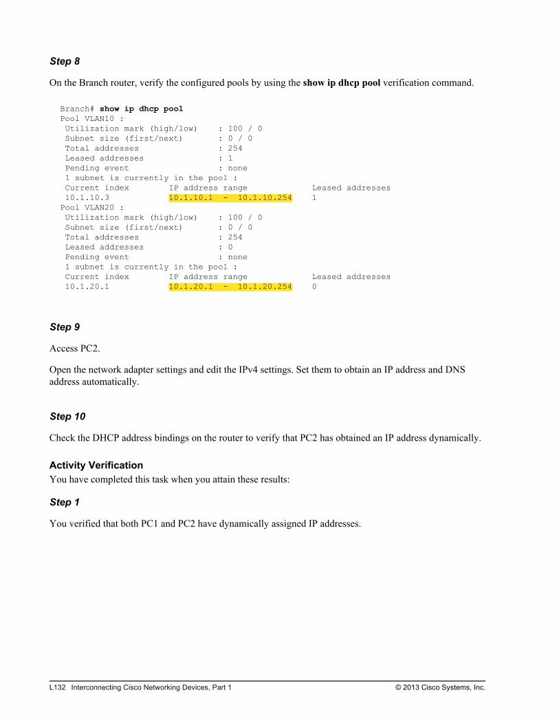
Step 8
On the Branch router, verify the configured pools by using the show ip dhcp pool verification command.
Branch# show ip dhcp poolPool VLAN10 : Utilization mark (high/low) : 100 / 0 Subnet size (first/next) : 0 / 0 Total addresses : 254 Leased addresses : 1 Pending event : none 1 subnet is currently in the pool : Current index IP address range Leased addresses 10.1.10.3 10.1.10.1 - 10.1.10.254 1Pool VLAN20 : Utilization mark (high/low) : 100 / 0 Subnet size (first/next) : 0 / 0 Total addresses : 254 Leased addresses : 0 Pending event : none 1 subnet is currently in the pool : Current index IP address range Leased addresses 10.1.20.1 10.1.20.1 - 10.1.20.254 0
Step 9
Access PC2.
Open the network adapter settings and edit the IPv4 settings. Set them to obtain an IP address and DNSaddress automatically.
Step 10
Check the DHCP address bindings on the router to verify that PC2 has obtained an IP address dynamically.
Activity VerificationYou have completed this task when you attain these results:
Step 1
You verified that both PC1 and PC2 have dynamically assigned IP addresses.
L132 Interconnecting Cisco Networking Devices, Part 1 © 2013 Cisco Systems, Inc.
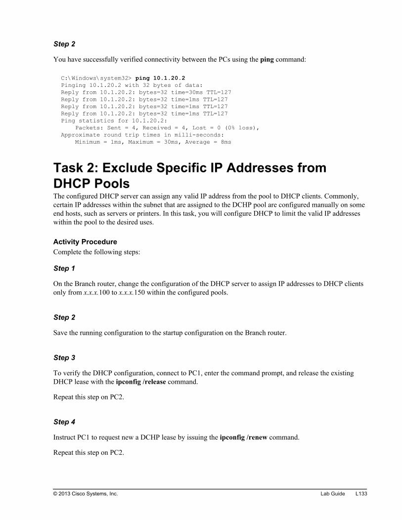
Step 2
You have successfully verified connectivity between the PCs using the ping command:
C:\Windows\system32> ping 10.1.20.2Pinging 10.1.20.2 with 32 bytes of data:Reply from 10.1.20.2: bytes=32 time=30ms TTL=127Reply from 10.1.20.2: bytes=32 time=1ms TTL=127Reply from 10.1.20.2: bytes=32 time=1ms TTL=127Reply from 10.1.20.2: bytes=32 time=1ms TTL=127Ping statistics for 10.1.20.2: Packets: Sent = 4, Received = 4, Lost = 0 (0% loss),Approximate round trip times in milli-seconds: Minimum = 1ms, Maximum = 30ms, Average = 8ms
Task 2: Exclude Specific IP Addresses fromDHCP PoolsThe configured DHCP server can assign any valid IP address from the pool to DHCP clients. Commonly,certain IP addresses within the subnet that are assigned to the DCHP pool are configured manually on someend hosts, such as servers or printers. In this task, you will configure DHCP to limit the valid IP addresseswithin the pool to the desired uses.
Activity ProcedureComplete the following steps:
Step 1
On the Branch router, change the configuration of the DHCP server to assign IP addresses to DHCP clientsonly from x.x.x.100 to x.x.x.150 within the configured pools.
Step 2
Save the running configuration to the startup configuration on the Branch router.
Step 3
To verify the DHCP configuration, connect to PC1, enter the command prompt, and release the existingDHCP lease with the ipconfig /release command.
Repeat this step on PC2.
Step 4
Instruct PC1 to request new a DCHP lease by issuing the ipconfig /renew command.
Repeat this step on PC2.
© 2013 Cisco Systems, Inc. Lab Guide L133
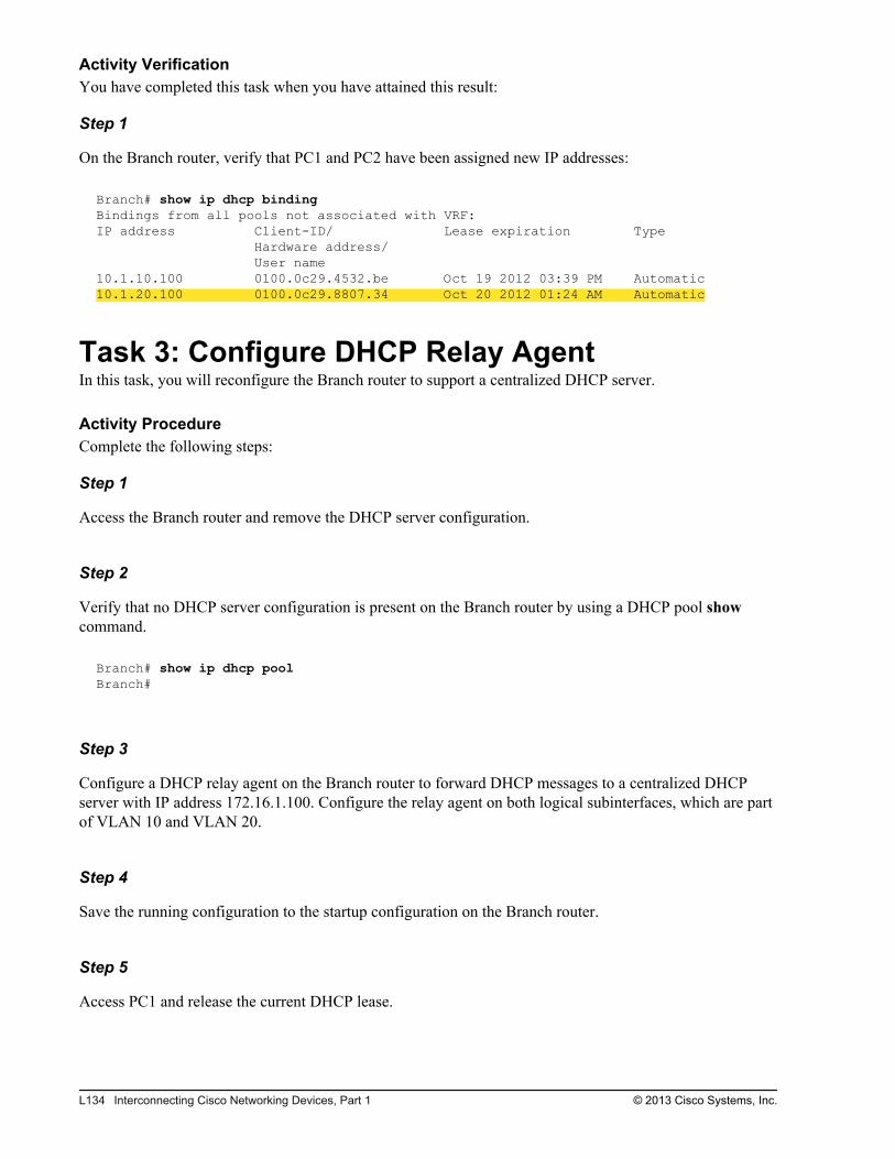
Activity VerificationYou have completed this task when you have attained this result:
Step 1
On the Branch router, verify that PC1 and PC2 have been assigned new IP addresses:
Branch# show ip dhcp bindingBindings from all pools not associated with VRF:IP address Client-ID/ Lease expiration Type Hardware address/ User name10.1.10.100 0100.0c29.4532.be Oct 19 2012 03:39 PM Automatic10.1.20.100 0100.0c29.8807.34 Oct 20 2012 01:24 AM Automatic
Task 3: Configure DHCP Relay AgentIn this task, you will reconfigure the Branch router to support a centralized DHCP server.
Activity ProcedureComplete the following steps:
Step 1
Access the Branch router and remove the DHCP server configuration.
Step 2
Verify that no DHCP server configuration is present on the Branch router by using a DHCP pool showcommand.
Branch# show ip dhcp poolBranch#
Step 3
Configure a DHCP relay agent on the Branch router to forward DHCP messages to a centralized DHCPserver with IP address 172.16.1.100. Configure the relay agent on both logical subinterfaces, which are partof VLAN 10 and VLAN 20.
Step 4
Save the running configuration to the startup configuration on the Branch router.
Step 5
Access PC1 and release the current DHCP lease.
L134 Interconnecting Cisco Networking Devices, Part 1 © 2013 Cisco Systems, Inc.
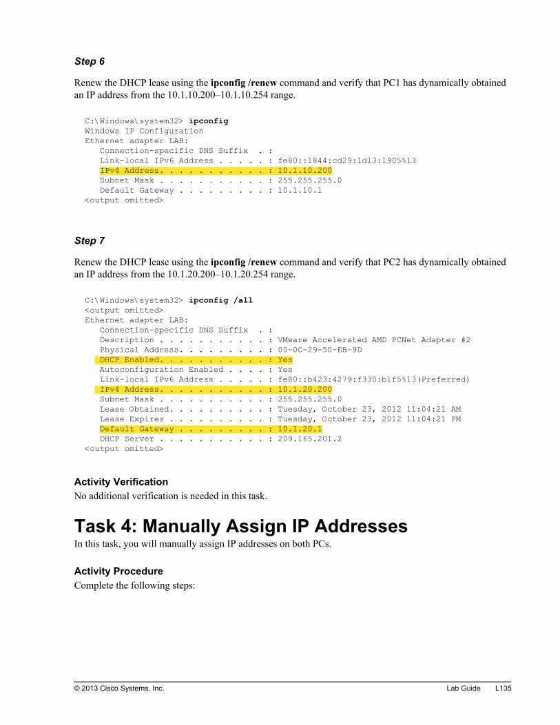
Step 6
Renew the DHCP lease using the ipconfig /renew command and verify that PC1 has dynamically obtainedan IP address from the 10.1.10.200–10.1.10.254 range.
C:\Windows\system32> ipconfigWindows IP ConfigurationEthernet adapter LAB: Connection-specific DNS Suffix . : Link-local IPv6 Address . . . . . : fe80::1844:cd29:1d13:1905%13 IPv4 Address. . . . . . . . . . . : 10.1.10.200 Subnet Mask . . . . . . . . . . . : 255.255.255.0 Default Gateway . . . . . . . . . : 10.1.10.1<output omitted>
Step 7
Renew the DHCP lease using the ipconfig /renew command and verify that PC2 has dynamically obtainedan IP address from the 10.1.20.200–10.1.20.254 range.
C:\Windows\system32> ipconfig /all<output omitted>Ethernet adapter LAB: Connection-specific DNS Suffix . : Description . . . . . . . . . . . : VMware Accelerated AMD PCNet Adapter #2 Physical Address. . . . . . . . . : 00-0C-29-50-EB-9D DHCP Enabled. . . . . . . . . . . : Yes Autoconfiguration Enabled . . . . : Yes Link-local IPv6 Address . . . . . : fe80::b423:4279:f330:b1f5%13(Preferred) IPv4 Address. . . . . . . . . . . : 10.1.20.200 Subnet Mask . . . . . . . . . . . : 255.255.255.0 Lease Obtained. . . . . . . . . . : Tuesday, October 23, 2012 11:04:21 AM Lease Expires . . . . . . . . . . : Tuesday, October 23, 2012 11:04:21 PM Default Gateway . . . . . . . . . : 10.1.20.1 DHCP Server . . . . . . . . . . . : 209.165.201.2<output omitted>
Activity VerificationNo additional verification is needed in this task.
Task 4: Manually Assign IP AddressesIn this task, you will manually assign IP addresses on both PCs.
Activity ProcedureComplete the following steps:
© 2013 Cisco Systems, Inc. Lab Guide L135
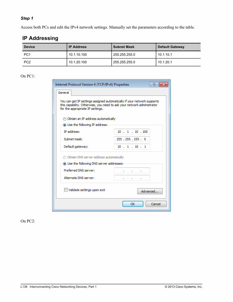
Step 1
Access both PCs and edit the IPv4 network settings. Manually set the parameters according to the table.
IP AddressingDevice IP Address Subnet Mask Default Gateway
PC1 10.1.10.100 255.255.255.0 10.1.10.1
PC2 10.1.20.100 255.255.255.0 10.1.20.1
On PC1:
On PC2:
L136 Interconnecting Cisco Networking Devices, Part 1 © 2013 Cisco Systems, Inc.
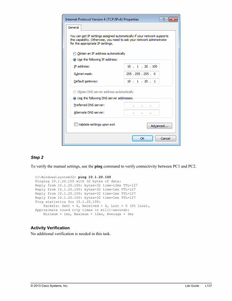
Step 2
To verify the manual settings, use the ping command to verify connectivity between PC1 and PC2.
C:\Windows\system32> ping 10.1.20.100Pinging 10.1.20.100 with 32 bytes of data:Reply from 10.1.20.100: bytes=32 time=12ms TTL=127Reply from 10.1.20.100: bytes=32 time=1ms TTL=127Reply from 10.1.20.100: bytes=32 time=1ms TTL=127Reply from 10.1.20.100: bytes=32 time=1ms TTL=127Ping statistics for 10.1.20.100: Packets: Sent = 4, Received = 4, Lost = 0 (0% loss),Approximate round trip times in milli-seconds: Minimum = 1ms, Maximum = 12ms, Average = 3ms
Activity VerificationNo additional verification is needed in this task.
© 2013 Cisco Systems, Inc. Lab Guide L137

L138 Interconnecting Cisco Networking Devices, Part 1 © 2013 Cisco Systems, Inc.
Lab 4-3: Implementing OSPF
Activity OverviewObjectivesAfter completing this activity, you will be able to meet these objectives:
Configure a WAN interface
Configure OSPF
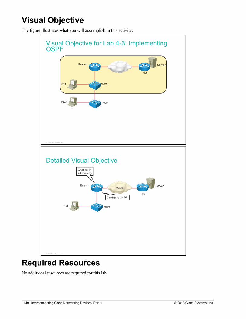
Visual ObjectiveThe figure illustrates what you will accomplish in this activity.
Visual Objective for Lab 4-3: ImplementingOSPF
Server
PC1
PC2
SW1
SW2
Branch
HQ
© 2013 Cisco Systems, Inc.
Detailed Visual Objective
ServerBranch
HQ
PC1 SW1
Change IP
addressing
Configure OSPF
WAN
© 2013 Cisco Systems, Inc.
Required ResourcesNo additional resources are required for this lab.
L140 Interconnecting Cisco Networking Devices, Part 1 © 2013 Cisco Systems, Inc.

Command ListThe table describes the commands that are used in this activity. The commands are listed in alphabeticalorder so that you can easily locate the information that you need. Refer to this list if you need configurationcommand assistance during the lab activity.
Cisco CommandsCommand Description
interface interface Enters interface configuration mode.
ip address ip_address network_mask Sets an IP address, along with the subnet mask, on an interface.Enters interface configuration mode to issue this command.
router ospf process_id Starts the OSPF routing process with the specified process ID. Theprocess ID is of local significance, so two routers can have differentprocess IDs and still become neighbors.
show ip interfaces brief Shows a brief version of the operational state and IP information of allinterfaces.
show ip ospf interface Displays interface information that is related to OSPF.
show ip ospf neighbor Shows all OSPF neighbors of the router.
show ip route Displays the IP route table.
Microsoft Windows CommandsCommand Description
ping ip_address Issues a ping to the specified IP address.
Job AidsThese job aids are available to help you complete the lab activity.
The table shows the hardware that is used in the lab and the operating system that is running on the devices.
Device Hardware Operating System
Branch Cisco 2901 Integrated Services Router c2900-universalk9-mz.SPA.152-4.M1
Headquarters
Cisco 2901 Integrated Services Router c2900-universalk9-mz.SPA.152-4.M1
SW1 Catalyst 2960 Series Switch c2960-lanbasek9-mz.150-1.SE3
SW2 Catalyst 2960 Series Switch c2960-lanlitek9-mz.150-1.SE3
PC1 Any PC Microsoft Windows 7
PC2 Any PC Microsoft Windows 7
The table shows the usernames and passwords that are used to access the lab equipment.
© 2013 Cisco Systems, Inc. Lab Guide L141
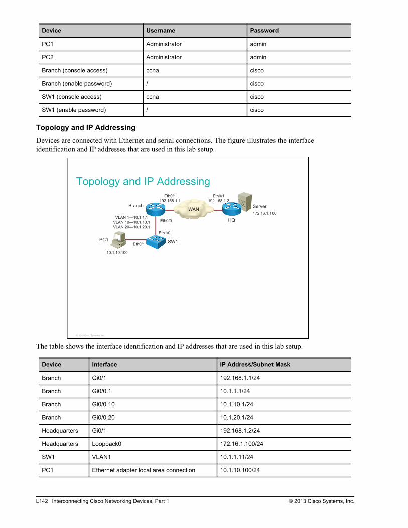
Device Username Password
PC1 Administrator admin
PC2 Administrator admin
Branch (console access) ccna cisco
Branch (enable password) / cisco
SW1 (console access) ccna cisco
SW1 (enable password) / cisco
Topology and IP Addressing
Devices are connected with Ethernet and serial connections. The figure illustrates the interfaceidentification and IP addresses that are used in this lab setup.
Topology and IP Addressing
ServerBranch
HQ
Eth0/1Eth0/1
172.16.1.100
PC1SW1
Eth0/1
Eth0/0
Eth1/0
10.1.10.100
WAN
VLAN 1—10.1.1.1
VLAN 10—10.1.10.1
VLAN 20—10.1.20.1
192.168.1.2192.168.1.1
© 2013 Cisco Systems, Inc.
The table shows the interface identification and IP addresses that are used in this lab setup.
Device Interface IP Address/Subnet Mask
Branch Gi0/1 192.168.1.1/24
Branch Gi0/0.1 10.1.1.1/24
Branch Gi0/0.10 10.1.10.1/24
Branch Gi0/0.20 10.1.20.1/24
Headquarters Gi0/1 192.168.1.2/24
Headquarters Loopback0 172.16.1.100/24
SW1 VLAN1 10.1.1.11/24
PC1 Ethernet adapter local area connection 10.1.10.100/24
L142 Interconnecting Cisco Networking Devices, Part 1 © 2013 Cisco Systems, Inc.
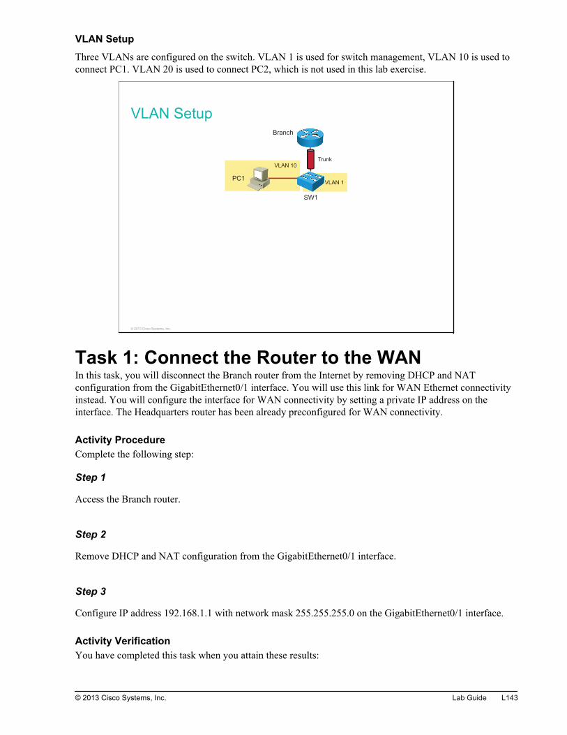
VLAN Setup
Three VLANs are configured on the switch. VLAN 1 is used for switch management, VLAN 10 is used toconnect PC1. VLAN 20 is used to connect PC2, which is not used in this lab exercise.
VLAN Setup
VLAN 1
VLAN 10
PC1
SW1
Branch
Trunk
© 2013 Cisco Systems, Inc.
Task 1: Connect the Router to the WANIn this task, you will disconnect the Branch router from the Internet by removing DHCP and NATconfiguration from the GigabitEthernet0/1 interface. You will use this link for WAN Ethernet connectivityinstead. You will configure the interface for WAN connectivity by setting a private IP address on theinterface. The Headquarters router has been already preconfigured for WAN connectivity.
Activity ProcedureComplete the following step:
Step 1
Access the Branch router.
Step 2
Remove DHCP and NAT configuration from the GigabitEthernet0/1 interface.
Step 3
Configure IP address 192.168.1.1 with network mask 255.255.255.0 on the GigabitEthernet0/1 interface.
Activity VerificationYou have completed this task when you attain these results:
© 2013 Cisco Systems, Inc. Lab Guide L143
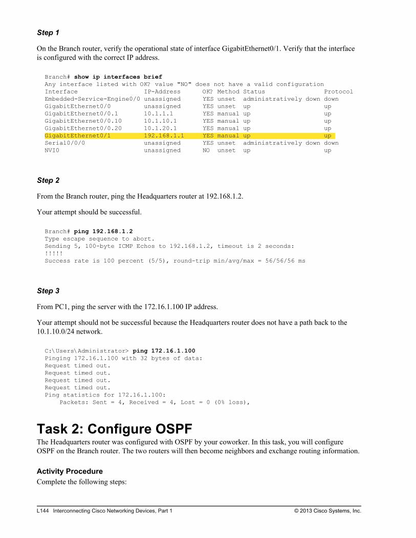
Step 1
On the Branch router, verify the operational state of interface GigabitEthernet0/1. Verify that the interfaceis configured with the correct IP address.
Branch# show ip interfaces briefAny interface listed with OK? value "NO" does not have a valid configurationInterface IP-Address OK? Method Status ProtocolEmbedded-Service-Engine0/0 unassigned YES unset administratively down down GigabitEthernet0/0 unassigned YES unset up up GigabitEthernet0/0.1 10.1.1.1 YES manual up up GigabitEthernet0/0.10 10.1.10.1 YES manual up up GigabitEthernet0/0.20 10.1.20.1 YES manual up up GigabitEthernet0/1 192.168.1.1 YES manual up up Serial0/0/0 unassigned YES unset administratively down down NVI0 unassigned NO unset up up
Step 2
From the Branch router, ping the Headquarters router at 192.168.1.2.
Your attempt should be successful.
Branch# ping 192.168.1.2Type escape sequence to abort.Sending 5, 100-byte ICMP Echos to 192.168.1.2, timeout is 2 seconds:!!!!!Success rate is 100 percent (5/5), round-trip min/avg/max = 56/56/56 ms
Step 3
From PC1, ping the server with the 172.16.1.100 IP address.
Your attempt should not be successful because the Headquarters router does not have a path back to the10.1.10.0/24 network.
C:\Users\Administrator> ping 172.16.1.100Pinging 172.16.1.100 with 32 bytes of data:Request timed out.Request timed out.Request timed out.Request timed out.Ping statistics for 172.16.1.100: Packets: Sent = 4, Received = 4, Lost = 0 (0% loss),
Task 2: Configure OSPFThe Headquarters router was configured with OSPF by your coworker. In this task, you will configureOSPF on the Branch router. The two routers will then become neighbors and exchange routing information.
Activity ProcedureComplete the following steps:
L144 Interconnecting Cisco Networking Devices, Part 1 © 2013 Cisco Systems, Inc.
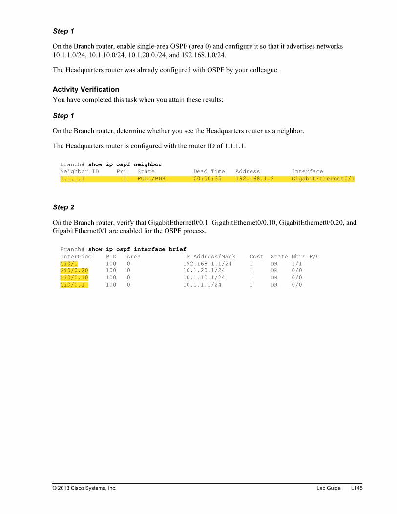
Step 1
On the Branch router, enable single-area OSPF (area 0) and configure it so that it advertises networks10.1.1.0/24, 10.1.10.0/24, 10.1.20.0./24, and 192.168.1.0/24.
The Headquarters router was already configured with OSPF by your colleague.
Activity VerificationYou have completed this task when you attain these results:
Step 1
On the Branch router, determine whether you see the Headquarters router as a neighbor.
The Headquarters router is configured with the router ID of 1.1.1.1.
Branch# show ip ospf neighbor Neighbor ID Pri State Dead Time Address Interface1.1.1.1 1 FULL/BDR 00:00:35 192.168.1.2 GigabitEthernet0/1
Step 2
On the Branch router, verify that GigabitEthernet0/0.1, GigabitEthernet0/0.10, GigabitEthernet0/0.20, andGigabitEthernet0/1 are enabled for the OSPF process.
Branch# show ip ospf interface briefInterGice PID Area IP Address/Mask Cost State Nbrs F/CGi0/1 100 0 192.168.1.1/24 1 DR 1/1Gi0/0.20 100 0 10.1.20.1/24 1 DR 0/0Gi0/0.10 100 0 10.1.10.1/24 1 DR 0/0Gi0/0.1 100 0 10.1.1.1/24 1 DR 0/0
© 2013 Cisco Systems, Inc. Lab Guide L145

Step 3
On the Branch router, view the routing table. Note the entry for the 172.16.1.0/24 network that wasacquired via the OSPF routing process.
Branch# show ip routeCodes: L - local, C - connected, S - static, R - RIP, M - mobile, B - BGP D - EIGRP, EX - EIGRP external, O - OSPF, IA - OSPF inter area N1 - OSPF NSSA external type 1, N2 - OSPF NSSA external type 2 E1 - OSPF external type 1, E2 - OSPF external type 2 i - IS-IS, su - IS-IS summary, L1 - IS-IS level-1, L2 - IS-IS level-2 ia - IS-IS inter area, * - candidate default, U - per-user static route o - ODR, P - periodic downloaded static route, H - NHRP, l - LISP + - replicated route, % - next hop overrideGateway of last resort is 0.0.0.0 to network 0.0.0.0S* 0.0.0.0/0 is directly connected, GigabitEthernet0/1 10.0.0.0/8 is variably subnetted, 6 subnets, 2 masksC 10.1.1.0/24 is directly connected, GigabitEthernet0/0.1L 10.1.1.1/32 is directly connected, GigabitEthernet0/0.1C 10.1.10.0/24 is directly connected, GigabitEthernet0/0.10L 10.1.10.1/32 is directly connected, GigabitEthernet0/0.10C 10.1.20.0/24 is directly connected, GigabitEthernet0/0.20L 10.1.20.1/32 is directly connected, GigabitEthernet0/0.20 172.16.0.0/32 is subnetted, 1 subnetsO 172.16.1.100 [110/2] via 192.168.1.2, 00:07:00, GigabitEthernet0/1 192.168.1.0/24 is variably subnetted, 2 subnets, 2 masksC 192.168.1.0/24 is directly connected, GigabitEthernet0/1L 192.168.1.1/32 is directly connected, GigabitEthernet0/1
Step 4
From PC1, ping the 172.16.1.100 server. Your attempt should be successful because the HQ router nowknows how to get back to the 10.1.10.0/24 network.
C:\Users\Administrator>ping 172.16.1.100 Pinging 172.16.1.100 with 32 bytes of data:Reply from 172.16.1.100: bytes=32 time=44ms TTL=128Reply from 172.16.1.100: bytes=32 time=41ms TTL=128Reply from 172.16.1.100: bytes=32 time=36ms TTL=128Reply from 172.16.1.100: bytes=32 time=36ms TTL=128Ping statistics for 172.16.1.100: Packets: Sent = 4, Received = 4, Lost = 0 (0% loss), Approximate round trip times in milli-seconds: Minimum = 36ms, Maximum = 44ms, Average = 39ms
L146 Interconnecting Cisco Networking Devices, Part 1 © 2013 Cisco Systems, Inc.
Lab 5-1: Configure and VerifyBasic IPv6
Activity OverviewObjectivesIn this activity, you will enable IPv6 globally and manually configure an IPv6 address on the interface.After completing this lab activity, you will be able to meet this objective:
Enable IPv6 support on a router and perform basic configuration
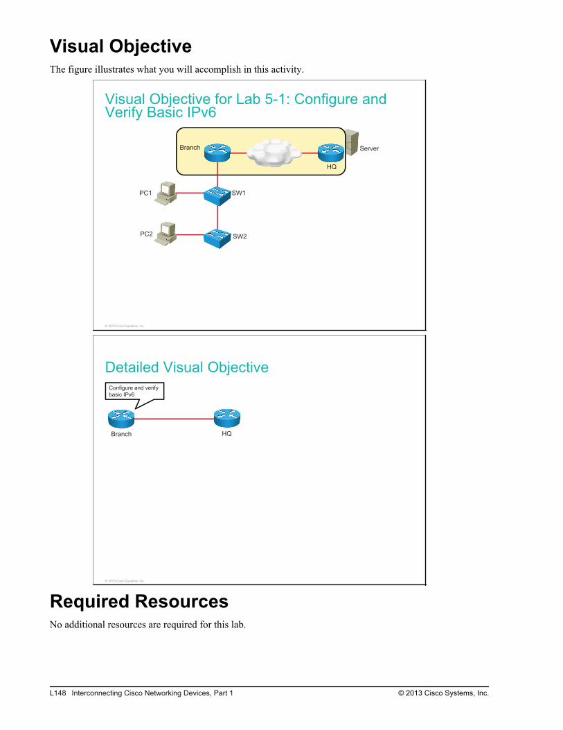
Visual ObjectiveThe figure illustrates what you will accomplish in this activity.
Visual Objective for Lab 5-1: Configure andVerify Basic IPv6
Server
PC1
PC2
SW1
SW2
Branch
HQ
© 2013 Cisco Systems, Inc.
Detailed Visual Objective
Branch HQ
Configure and verify
basic IPv6
© 2013 Cisco Systems, Inc.
Required ResourcesNo additional resources are required for this lab.
L148 Interconnecting Cisco Networking Devices, Part 1 © 2013 Cisco Systems, Inc.
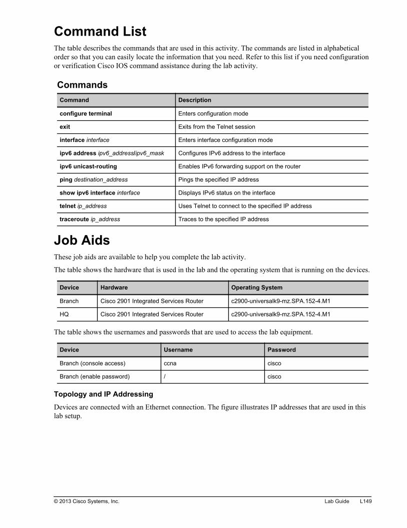
Command ListThe table describes the commands that are used in this activity. The commands are listed in alphabeticalorder so that you can easily locate the information that you need. Refer to this list if you need configurationor verification Cisco IOS command assistance during the lab activity.
CommandsCommand Description
configure terminal Enters configuration mode
exit Exits from the Telnet session
interface interface Enters interface configuration mode
ipv6 address ipv6_address/ipv6_mask Configures IPv6 address to the interface
ipv6 unicast-routing Enables IPv6 forwarding support on the router
ping destination_address Pings the specified IP address
show ipv6 interface interface Displays IPv6 status on the interface
telnet ip_address Uses Telnet to connect to the specified IP address
traceroute ip_address Traces to the specified IP address
Job AidsThese job aids are available to help you complete the lab activity.
The table shows the hardware that is used in the lab and the operating system that is running on the devices.
Device Hardware Operating System
Branch Cisco 2901 Integrated Services Router c2900-universalk9-mz.SPA.152-4.M1
HQ Cisco 2901 Integrated Services Router c2900-universalk9-mz.SPA.152-4.M1
The table shows the usernames and passwords that are used to access the lab equipment.
Device Username Password
Branch (console access) ccna cisco
Branch (enable password) / cisco
Topology and IP Addressing
Devices are connected with an Ethernet connection. The figure illustrates IP addresses that are used in thislab setup.
© 2013 Cisco Systems, Inc. Lab Guide L149
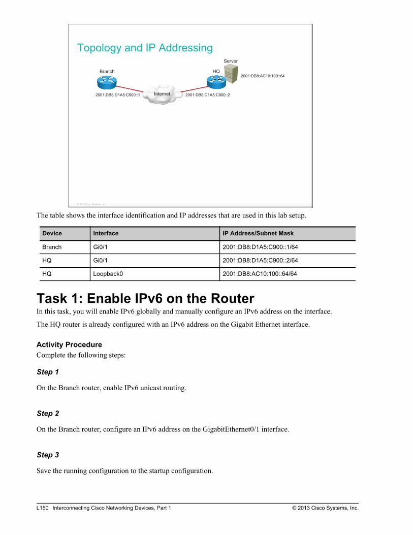
Topology and IP Addressing
Internet
Server
Branch HQ
2001:DB8:D1A5:C900::1 2001:DB8:D1A5:C900::2
2001:DB8:AC10:100::64
© 2013 Cisco Systems, Inc.
The table shows the interface identification and IP addresses that are used in this lab setup.
Device Interface IP Address/Subnet Mask
Branch Gi0/1 2001:DB8:D1A5:C900::1/64
HQ Gi0/1 2001:DB8:D1A5:C900::2/64
HQ Loopback0 2001:DB8:AC10:100::64/64
Task 1: Enable IPv6 on the RouterIn this task, you will enable IPv6 globally and manually configure an IPv6 address on the interface.
The HQ router is already configured with an IPv6 address on the Gigabit Ethernet interface.
Activity ProcedureComplete the following steps:
Step 1
On the Branch router, enable IPv6 unicast routing.
Step 2
On the Branch router, configure an IPv6 address on the GigabitEthernet0/1 interface.
Step 3
Save the running configuration to the startup configuration.
L150 Interconnecting Cisco Networking Devices, Part 1 © 2013 Cisco Systems, Inc.
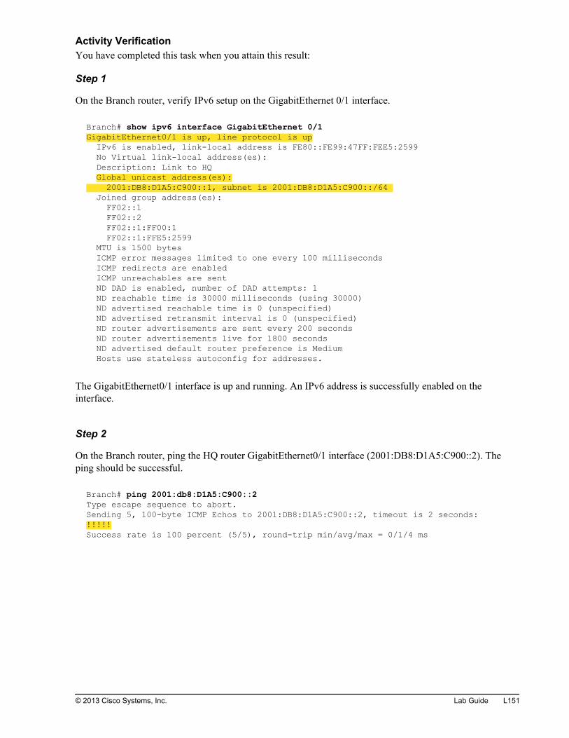
Activity VerificationYou have completed this task when you attain this result:
Step 1
On the Branch router, verify IPv6 setup on the GigabitEthernet 0/1 interface.
Branch# show ipv6 interface GigabitEthernet 0/1GigabitEthernet0/1 is up, line protocol is up IPv6 is enabled, link-local address is FE80::FE99:47FF:FEE5:2599 No Virtual link-local address(es): Description: Link to HQ Global unicast address(es): 2001:DB8:D1A5:C900::1, subnet is 2001:DB8:D1A5:C900::/64 Joined group address(es): FF02::1 FF02::2 FF02::1:FF00:1 FF02::1:FFE5:2599 MTU is 1500 bytes ICMP error messages limited to one every 100 milliseconds ICMP redirects are enabled ICMP unreachables are sent ND DAD is enabled, number of DAD attempts: 1 ND reachable time is 30000 milliseconds (using 30000) ND advertised reachable time is 0 (unspecified) ND advertised retransmit interval is 0 (unspecified) ND router advertisements are sent every 200 seconds ND router advertisements live for 1800 seconds ND advertised default router preference is Medium Hosts use stateless autoconfig for addresses.
The GigabitEthernet0/1 interface is up and running. An IPv6 address is successfully enabled on theinterface.
Step 2
On the Branch router, ping the HQ router GigabitEthernet0/1 interface (2001:DB8:D1A5:C900::2). Theping should be successful.
Branch# ping 2001:db8:D1A5:C900::2Type escape sequence to abort.Sending 5, 100-byte ICMP Echos to 2001:DB8:D1A5:C900::2, timeout is 2 seconds:!!!!!Success rate is 100 percent (5/5), round-trip min/avg/max = 0/1/4 ms
© 2013 Cisco Systems, Inc. Lab Guide L151

Step 3
On the Branch router, trace route to the IPv6 address 2001:DB8:D1A5:C900::2. You should see a responsefrom the HQ router.
Branch# traceroute 2001:db8:D1A5:C900::2Type escape sequence to abort.Tracing the route to 2001:DB8:D1A5:C900::2 1 2001:DB8:D1A5:C900::2 0 msec 4 msec 0 msec
Step 4
From the Branch router, use Telnet to connect to IPv6 address 2001:DB8:D1A5:C900::2. You should see asuccessful Telnet to the HQ router.
Branch# telnet 2001:db8:D1A5:C900::2Trying 2001:DB8:D1A5:C900::2 ... OpenHQ#
Disconnect from the HQ router by performing the exit command.
HQ# exit[Connection to 2001:db8:D1A5:C900::2 closed by foreign host]Branch#
L152 Interconnecting Cisco Networking Devices, Part 1 © 2013 Cisco Systems, Inc.
Lab 5-2: Configure and VerifyStateless Autoconfiguration
Activity OverviewObjectivesIn this activity, you will enable stateless autoconfiguration. After completing this lab activity, you will beable to meet this objective:
Configure and verify stateless autoconfiguration
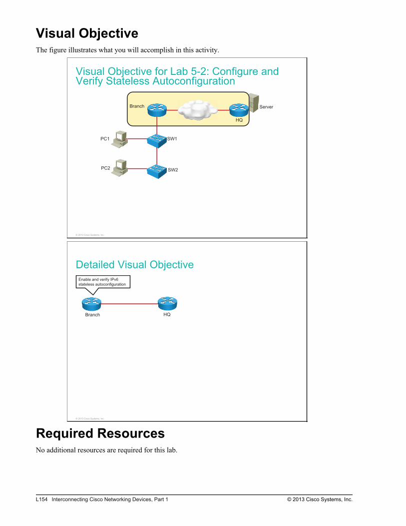
Visual ObjectiveThe figure illustrates what you will accomplish in this activity.
Visual Objective for Lab 5-2: Configure andVerify Stateless Autoconfiguration
Server
PC1
PC2
SW1
SW2
Branch
HQ
© 2013 Cisco Systems, Inc.
Detailed Visual Objective
Branch HQ
Enable and verify IPv6
stateless autoconfiguration
© 2013 Cisco Systems, Inc.
Required ResourcesNo additional resources are required for this lab.
L154 Interconnecting Cisco Networking Devices, Part 1 © 2013 Cisco Systems, Inc.

Command ListThe table describes the commands that are used in this activity. The commands are listed in alphabeticalorder so that you can easily locate the information that you need. Refer to this list if you need configurationor verification Cisco IOS command assistance during the lab activity.
CommandsCommand Description
configure terminal Enters configuration mode
exit Exits from the Telnet session
interface interface Enters interface configuration mode
ipv6 address autoconfig Enables IPv6 autoconfiguration on the interface
ping destination_address Pings the specified IP address
show ipv6 interface interface Displays IPv6 status on the interface
telnet ip_address Uses Telnet to connect to the specified IP address
traceroute ip_address Traces to the specified IP address
Job AidsThese job aids are available to help you complete the lab activity.
The table shows the hardware that is used in the lab and the operating system that is running on the devices.
Device Hardware Operating System
Branch Cisco 2901 Integrated Services Router c2900-universalk9-mz.SPA.152-4.M1
HQ Cisco 2901 Integrated Services Router c2900-universalk9-mz.SPA.152-4.M1
The table shows the usernames and passwords that are used to access the lab equipment.
Device Username Password
Branch (console access) ccna cisco
Branch (enable password) / cisco
Topology and IP Addressing
Devices are connected with an Ethernet connection. The figure illustrates IP addresses that are used in thislab setup.
© 2013 Cisco Systems, Inc. Lab Guide L155
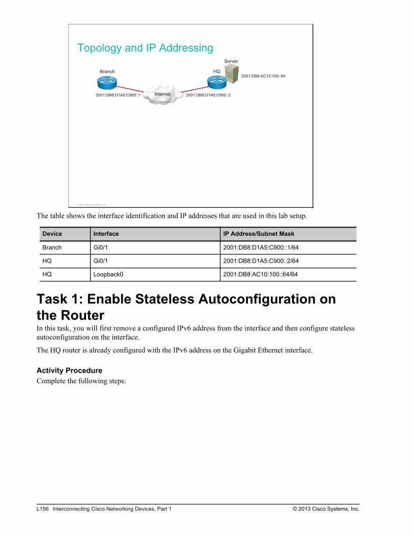
Topology and IP Addressing
Internet
Server
Branch HQ
2001:DB8:D1A5:C900::1 2001:DB8:D1A5:C900::2
2001:DB8:AC10:100::64
© 2013 Cisco Systems, Inc.
The table shows the interface identification and IP addresses that are used in this lab setup.
Device Interface IP Address/Subnet Mask
Branch Gi0/1 2001:DB8:D1A5:C900::1/64
HQ Gi0/1 2001:DB8:D1A5:C900::2/64
HQ Loopback0 2001:DB8:AC10:100::64/64
Task 1: Enable Stateless Autoconfiguration onthe RouterIn this task, you will first remove a configured IPv6 address from the interface and then configure statelessautoconfiguration on the interface.
The HQ router is already configured with the IPv6 address on the Gigabit Ethernet interface.
Activity ProcedureComplete the following steps:
L156 Interconnecting Cisco Networking Devices, Part 1 © 2013 Cisco Systems, Inc.
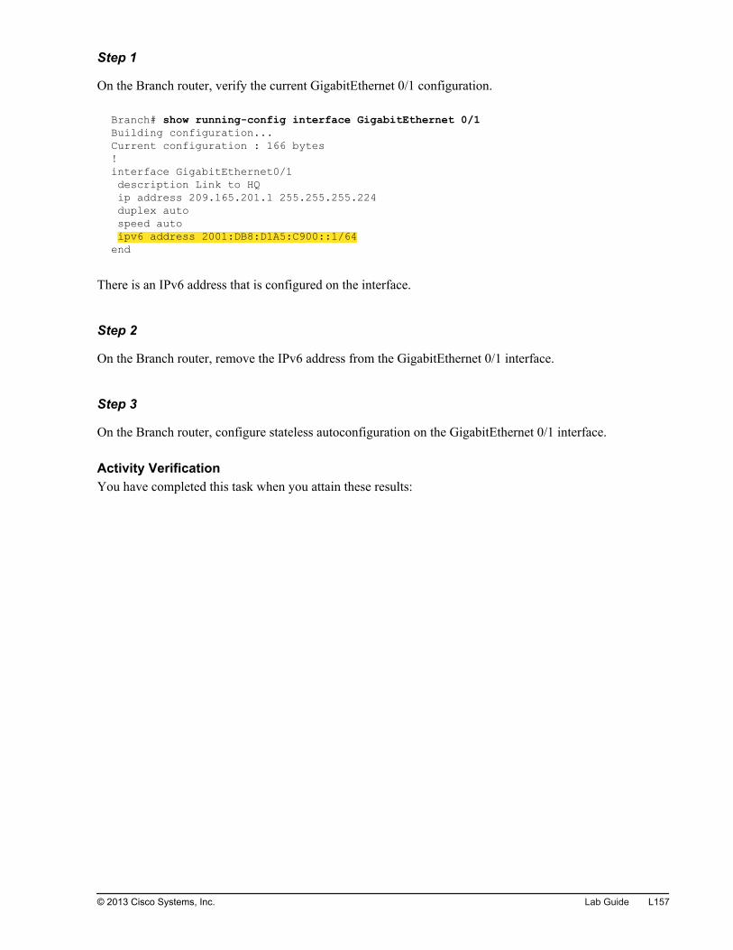
Step 1
On the Branch router, verify the current GigabitEthernet 0/1 configuration.
Branch# show running-config interface GigabitEthernet 0/1Building configuration...Current configuration : 166 bytes!interface GigabitEthernet0/1 description Link to HQ ip address 209.165.201.1 255.255.255.224 duplex auto speed auto ipv6 address 2001:DB8:D1A5:C900::1/64end
There is an IPv6 address that is configured on the interface.
Step 2
On the Branch router, remove the IPv6 address from the GigabitEthernet 0/1 interface.
Step 3
On the Branch router, configure stateless autoconfiguration on the GigabitEthernet 0/1 interface.
Activity VerificationYou have completed this task when you attain these results:
© 2013 Cisco Systems, Inc. Lab Guide L157
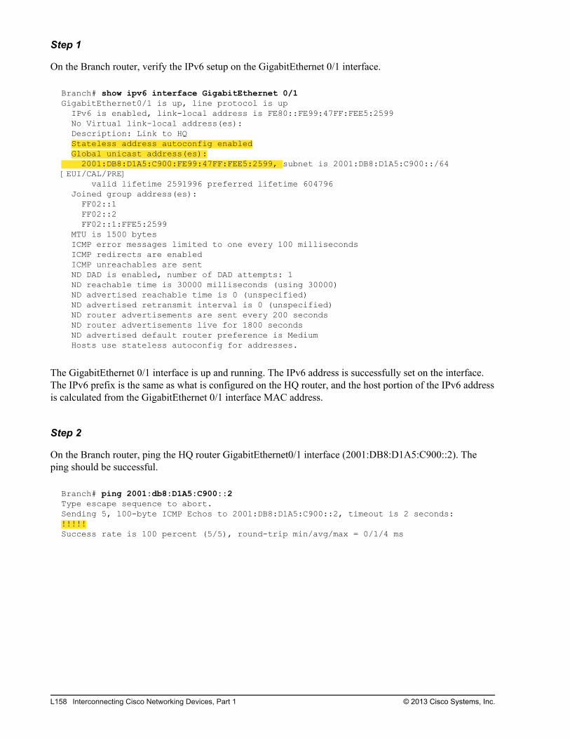
Step 1
On the Branch router, verify the IPv6 setup on the GigabitEthernet 0/1 interface.
Branch# show ipv6 interface GigabitEthernet 0/1GigabitEthernet0/1 is up, line protocol is up IPv6 is enabled, link-local address is FE80::FE99:47FF:FEE5:2599 No Virtual link-local address(es): Description: Link to HQ Stateless address autoconfig enabled Global unicast address(es): 2001:DB8:D1A5:C900:FE99:47FF:FEE5:2599, subnet is 2001:DB8:D1A5:C900::/64 [EUI/CAL/PRE] valid lifetime 2591996 preferred lifetime 604796 Joined group address(es): FF02::1 FF02::2 FF02::1:FFE5:2599 MTU is 1500 bytes ICMP error messages limited to one every 100 milliseconds ICMP redirects are enabled ICMP unreachables are sent ND DAD is enabled, number of DAD attempts: 1 ND reachable time is 30000 milliseconds (using 30000) ND advertised reachable time is 0 (unspecified) ND advertised retransmit interval is 0 (unspecified) ND router advertisements are sent every 200 seconds ND router advertisements live for 1800 seconds ND advertised default router preference is Medium Hosts use stateless autoconfig for addresses.
The GigabitEthernet 0/1 interface is up and running. The IPv6 address is successfully set on the interface.The IPv6 prefix is the same as what is configured on the HQ router, and the host portion of the IPv6 addressis calculated from the GigabitEthernet 0/1 interface MAC address.
Step 2
On the Branch router, ping the HQ router GigabitEthernet0/1 interface (2001:DB8:D1A5:C900::2). Theping should be successful.
Branch# ping 2001:db8:D1A5:C900::2Type escape sequence to abort.Sending 5, 100-byte ICMP Echos to 2001:DB8:D1A5:C900::2, timeout is 2 seconds:!!!!!Success rate is 100 percent (5/5), round-trip min/avg/max = 0/1/4 ms
L158 Interconnecting Cisco Networking Devices, Part 1 © 2013 Cisco Systems, Inc.

Step 3
On the Branch router, trace route to the IPv6 address 2001:DB8:D1A5:C900::2. You should see a responsefrom the HQ router.
Branch# traceroute 2001:db8:D1A5:C900::2Type escape sequence to abort.Tracing the route to 2001:DB8:D1A5:C900::2 1 2001:DB8:D1A5:C900::2 0 msec 4 msec 0 msec
© 2013 Cisco Systems, Inc. Lab Guide L159

L160 Interconnecting Cisco Networking Devices, Part 1 © 2013 Cisco Systems, Inc.
Lab 5-3: Configure and VerifyIPv6 Routing
Activity OverviewObjectivesIn this activity, you will configure and verify IPv6 routing by enabling static routing and OSPFv3. Aftercompleting this lab activity, you will be able to meet these objectives:
Enable and verify static routing
Enable and verify OSPFv3
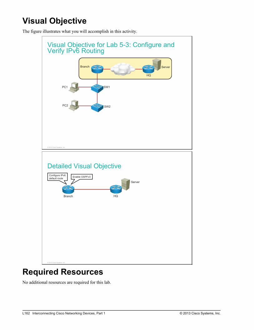
Visual ObjectiveThe figure illustrates what you will accomplish in this activity.
Visual Objective for Lab 5-3: Configure andVerify IPv6 Routing
Server
PC1
PC2
SW1
SW2
Branch
HQ
© 2013 Cisco Systems, Inc.
Detailed Visual Objective
Server
Branch HQ
Configure IPv6
default routeEnable OSPFv3
© 2013 Cisco Systems, Inc.
Required ResourcesNo additional resources are required for this lab.
L162 Interconnecting Cisco Networking Devices, Part 1 © 2013 Cisco Systems, Inc.
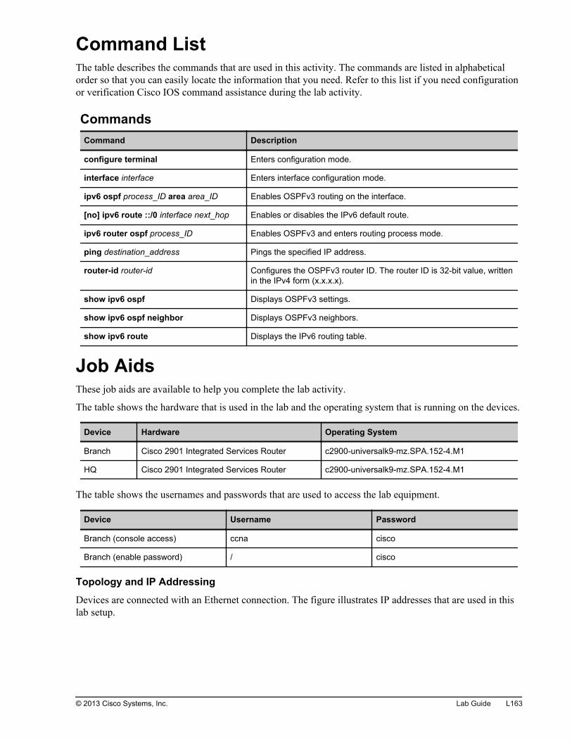
Command ListThe table describes the commands that are used in this activity. The commands are listed in alphabeticalorder so that you can easily locate the information that you need. Refer to this list if you need configurationor verification Cisco IOS command assistance during the lab activity.
CommandsCommand Description
configure terminal Enters configuration mode.
interface interface Enters interface configuration mode.
ipv6 ospf process_ID area area_ID Enables OSPFv3 routing on the interface.
[no] ipv6 route ::/0 interface next_hop Enables or disables the IPv6 default route.
ipv6 router ospf process_ID Enables OSPFv3 and enters routing process mode.
ping destination_address Pings the specified IP address.
router-id router-id Configures the OSPFv3 router ID. The router ID is 32-bit value, writtenin the IPv4 form (x.x.x.x).
show ipv6 ospf Displays OSPFv3 settings.
show ipv6 ospf neighbor Displays OSPFv3 neighbors.
show ipv6 route Displays the IPv6 routing table.
Job AidsThese job aids are available to help you complete the lab activity.
The table shows the hardware that is used in the lab and the operating system that is running on the devices.
Device Hardware Operating System
Branch Cisco 2901 Integrated Services Router c2900-universalk9-mz.SPA.152-4.M1
HQ Cisco 2901 Integrated Services Router c2900-universalk9-mz.SPA.152-4.M1
The table shows the usernames and passwords that are used to access the lab equipment.
Device Username Password
Branch (console access) ccna cisco
Branch (enable password) / cisco
Topology and IP Addressing
Devices are connected with an Ethernet connection. The figure illustrates IP addresses that are used in thislab setup.
© 2013 Cisco Systems, Inc. Lab Guide L163
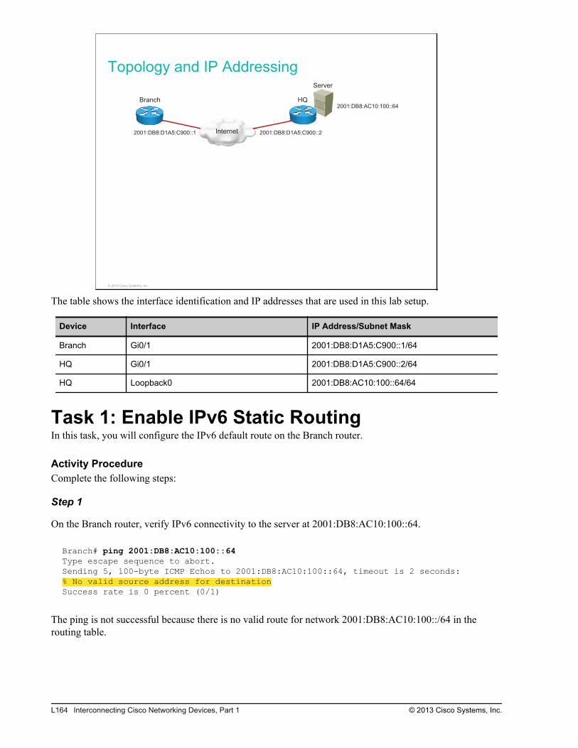
Topology and IP Addressing
Internet
Server
Branch HQ
2001:DB8:D1A5:C900::1 2001:DB8:D1A5:C900::2
2001:DB8:AC10:100::64
© 2013 Cisco Systems, Inc.
The table shows the interface identification and IP addresses that are used in this lab setup.
Device Interface IP Address/Subnet Mask
Branch Gi0/1 2001:DB8:D1A5:C900::1/64
HQ Gi0/1 2001:DB8:D1A5:C900::2/64
HQ Loopback0 2001:DB8:AC10:100::64/64
Task 1: Enable IPv6 Static RoutingIn this task, you will configure the IPv6 default route on the Branch router.
Activity ProcedureComplete the following steps:
Step 1
On the Branch router, verify IPv6 connectivity to the server at 2001:DB8:AC10:100::64.
Branch# ping 2001:DB8:AC10:100::64Type escape sequence to abort.Sending 5, 100-byte ICMP Echos to 2001:DB8:AC10:100::64, timeout is 2 seconds:% No valid source address for destinationSuccess rate is 0 percent (0/1)
The ping is not successful because there is no valid route for network 2001:DB8:AC10:100::/64 in therouting table.
L164 Interconnecting Cisco Networking Devices, Part 1 © 2013 Cisco Systems, Inc.
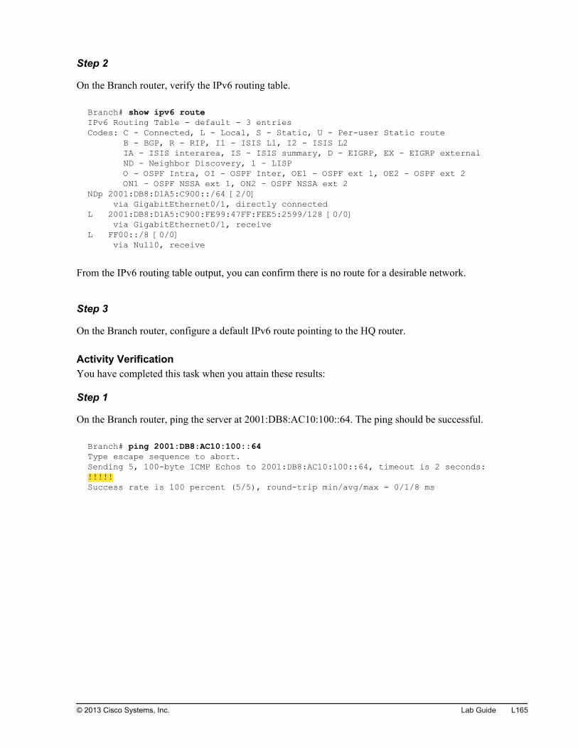
Step 2
On the Branch router, verify the IPv6 routing table.
Branch# show ipv6 routeIPv6 Routing Table - default - 3 entriesCodes: C - Connected, L - Local, S - Static, U - Per-user Static route B - BGP, R - RIP, I1 - ISIS L1, I2 - ISIS L2 IA - ISIS interarea, IS - ISIS summary, D - EIGRP, EX - EIGRP external ND - Neighbor Discovery, l - LISP O - OSPF Intra, OI - OSPF Inter, OE1 - OSPF ext 1, OE2 - OSPF ext 2 ON1 - OSPF NSSA ext 1, ON2 - OSPF NSSA ext 2NDp 2001:DB8:D1A5:C900::/64 [2/0] via GigabitEthernet0/1, directly connectedL 2001:DB8:D1A5:C900:FE99:47FF:FEE5:2599/128 [0/0] via GigabitEthernet0/1, receiveL FF00::/8 [0/0] via Null0, receive
From the IPv6 routing table output, you can confirm there is no route for a desirable network.
Step 3
On the Branch router, configure a default IPv6 route pointing to the HQ router.
Activity VerificationYou have completed this task when you attain these results:
Step 1
On the Branch router, ping the server at 2001:DB8:AC10:100::64. The ping should be successful.
Branch# ping 2001:DB8:AC10:100::64Type escape sequence to abort.Sending 5, 100-byte ICMP Echos to 2001:DB8:AC10:100::64, timeout is 2 seconds:!!!!!Success rate is 100 percent (5/5), round-trip min/avg/max = 0/1/8 ms
© 2013 Cisco Systems, Inc. Lab Guide L165
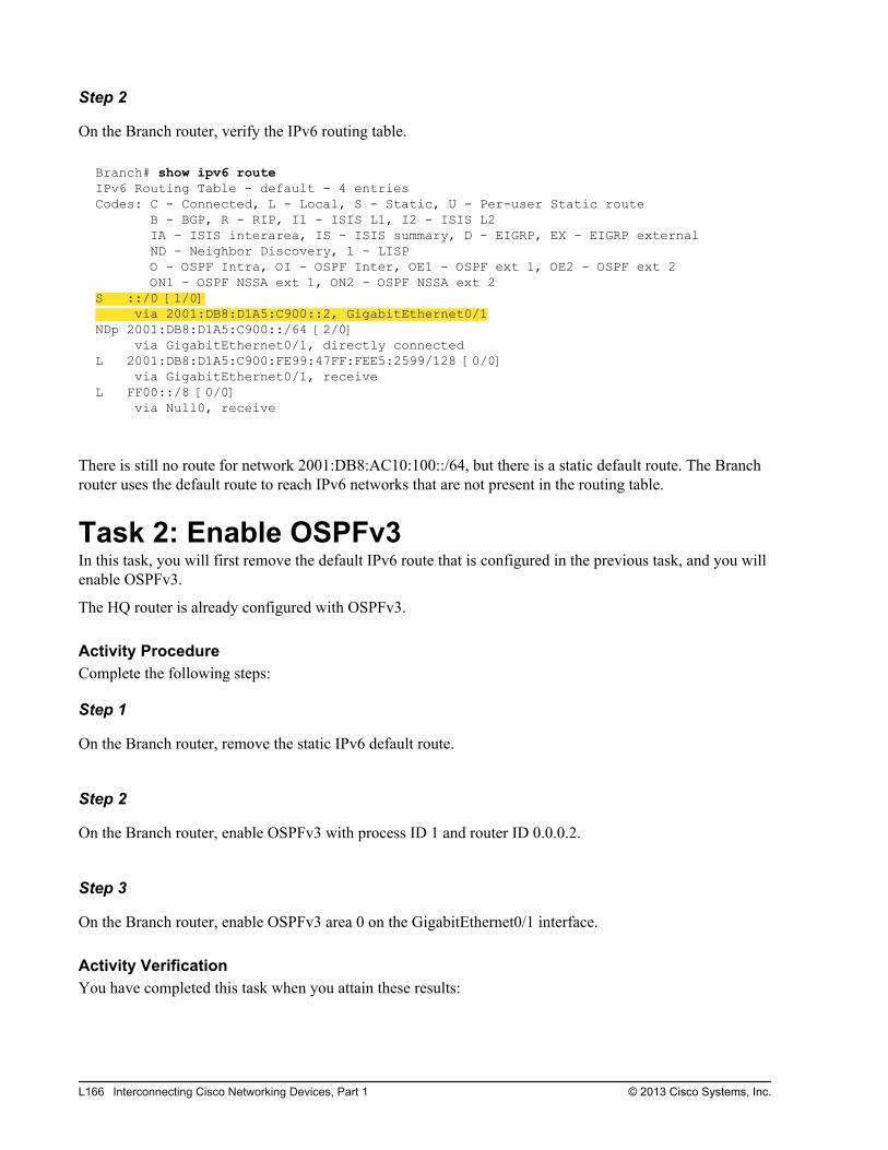
Step 2
On the Branch router, verify the IPv6 routing table.
Branch# show ipv6 route IPv6 Routing Table - default - 4 entriesCodes: C - Connected, L - Local, S - Static, U - Per-user Static route B - BGP, R - RIP, I1 - ISIS L1, I2 - ISIS L2 IA - ISIS interarea, IS - ISIS summary, D - EIGRP, EX - EIGRP external ND - Neighbor Discovery, l - LISP O - OSPF Intra, OI - OSPF Inter, OE1 - OSPF ext 1, OE2 - OSPF ext 2 ON1 - OSPF NSSA ext 1, ON2 - OSPF NSSA ext 2S ::/0 [1/0] via 2001:DB8:D1A5:C900::2, GigabitEthernet0/1NDp 2001:DB8:D1A5:C900::/64 [2/0] via GigabitEthernet0/1, directly connectedL 2001:DB8:D1A5:C900:FE99:47FF:FEE5:2599/128 [0/0] via GigabitEthernet0/1, receiveL FF00::/8 [0/0] via Null0, receive
There is still no route for network 2001:DB8:AC10:100::/64, but there is a static default route. The Branchrouter uses the default route to reach IPv6 networks that are not present in the routing table.
Task 2: Enable OSPFv3In this task, you will first remove the default IPv6 route that is configured in the previous task, and you willenable OSPFv3.
The HQ router is already configured with OSPFv3.
Activity ProcedureComplete the following steps:
Step 1
On the Branch router, remove the static IPv6 default route.
Step 2
On the Branch router, enable OSPFv3 with process ID 1 and router ID 0.0.0.2.
Step 3
On the Branch router, enable OSPFv3 area 0 on the GigabitEthernet0/1 interface.
Activity VerificationYou have completed this task when you attain these results:
L166 Interconnecting Cisco Networking Devices, Part 1 © 2013 Cisco Systems, Inc.
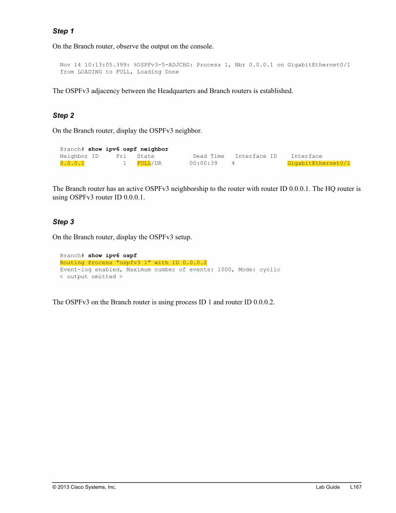
Step 1
On the Branch router, observe the output on the console.
Nov 14 10:13:05.399: %OSPFv3-5-ADJCHG: Process 1, Nbr 0.0.0.1 on GigabitEthernet0/1 from LOADING to FULL, Loading Done
The OSPFv3 adjacency between the Headquarters and Branch routers is established.
Step 2
On the Branch router, display the OSPFv3 neighbor.
Branch# show ipv6 ospf neighbor Neighbor ID Pri State Dead Time Interface ID Interface0.0.0.1 1 FULL/DR 00:00:39 4 GigabitEthernet0/1
The Branch router has an active OSPFv3 neighborship to the router with router ID 0.0.0.1. The HQ router isusing OSPFv3 router ID 0.0.0.1.
Step 3
On the Branch router, display the OSPFv3 setup.
Branch# show ipv6 ospfRouting Process "ospfv3 1" with ID 0.0.0.2Event-log enabled, Maximum number of events: 1000, Mode: cyclic< output omitted >
The OSPFv3 on the Branch router is using process ID 1 and router ID 0.0.0.2.
© 2013 Cisco Systems, Inc. Lab Guide L167
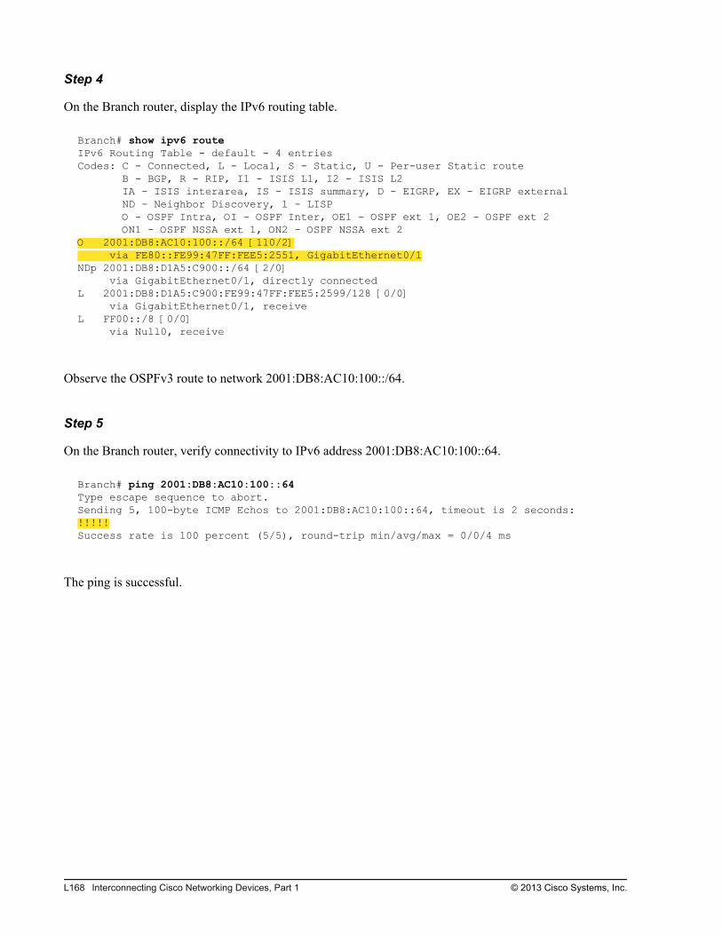
Step 4
On the Branch router, display the IPv6 routing table.
Branch# show ipv6 route IPv6 Routing Table - default - 4 entriesCodes: C - Connected, L - Local, S - Static, U - Per-user Static route B - BGP, R - RIP, I1 - ISIS L1, I2 - ISIS L2 IA - ISIS interarea, IS - ISIS summary, D - EIGRP, EX - EIGRP external ND - Neighbor Discovery, l - LISP O - OSPF Intra, OI - OSPF Inter, OE1 - OSPF ext 1, OE2 - OSPF ext 2 ON1 - OSPF NSSA ext 1, ON2 - OSPF NSSA ext 2O 2001:DB8:AC10:100::/64 [110/2] via FE80::FE99:47FF:FEE5:2551, GigabitEthernet0/1NDp 2001:DB8:D1A5:C900::/64 [2/0] via GigabitEthernet0/1, directly connectedL 2001:DB8:D1A5:C900:FE99:47FF:FEE5:2599/128 [0/0] via GigabitEthernet0/1, receiveL FF00::/8 [0/0] via Null0, receive
Observe the OSPFv3 route to network 2001:DB8:AC10:100::/64.
Step 5
On the Branch router, verify connectivity to IPv6 address 2001:DB8:AC10:100::64.
Branch# ping 2001:DB8:AC10:100::64Type escape sequence to abort.Sending 5, 100-byte ICMP Echos to 2001:DB8:AC10:100::64, timeout is 2 seconds:!!!!!Success rate is 100 percent (5/5), round-trip min/avg/max = 0/0/4 ms
The ping is successful.
L168 Interconnecting Cisco Networking Devices, Part 1 © 2013 Cisco Systems, Inc.
Lab S-1: ICND1 Superlab
Activity OverviewObjectivesIn this activity, you will repeat what you have learned throughout the course. After completing this activity,you will be able to meet these objectives:
Configure basic settings, VLANs, trunks, and port security on the Cisco switch
Configure inter-VLAN routing
Configure Internet connectivity
Configure WAN connectivity and dynamic routing protocol
Configure IPv6 connectivity in a LAN
Configure the OSPFv3 routing protocol
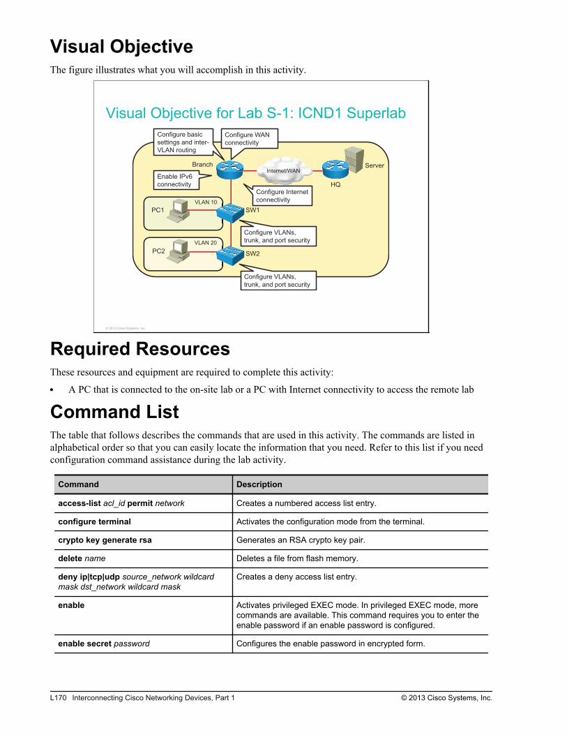
Visual ObjectiveThe figure illustrates what you will accomplish in this activity.
Visual Objective for Lab S-1: ICND1 Superlab
Server
PC1
PC2
SW1
SW2
Branch
HQ
VLAN 20
VLAN 10
Configure VLANs,
trunk, and port security
Configure WAN
connectivity
Configure Internet
connectivity
Configure VLANs,
trunk, and port security
Configure basic
settings and inter-
VLAN routing
Enable IPv6
connectivity
Internet/WAN
© 2013 Cisco Systems, Inc.
Required ResourcesThese resources and equipment are required to complete this activity:
A PC that is connected to the on-site lab or a PC with Internet connectivity to access the remote lab
Command ListThe table that follows describes the commands that are used in this activity. The commands are listed inalphabetical order so that you can easily locate the information that you need. Refer to this list if you needconfiguration command assistance during the lab activity.
Command Description
access-list acl_id permit network Creates a numbered access list entry.
configure terminal Activates the configuration mode from the terminal.
crypto key generate rsa Generates an RSA crypto key pair.
delete name Deletes a file from flash memory.
deny ip|tcp|udp source_network wildcardmask dst_network wildcard mask
Creates a deny access list entry.
enable Activates privileged EXEC mode. In privileged EXEC mode, morecommands are available. This command requires you to enter theenable password if an enable password is configured.
enable secret password Configures the enable password in encrypted form.
L170 Interconnecting Cisco Networking Devices, Part 1 © 2013 Cisco Systems, Inc.
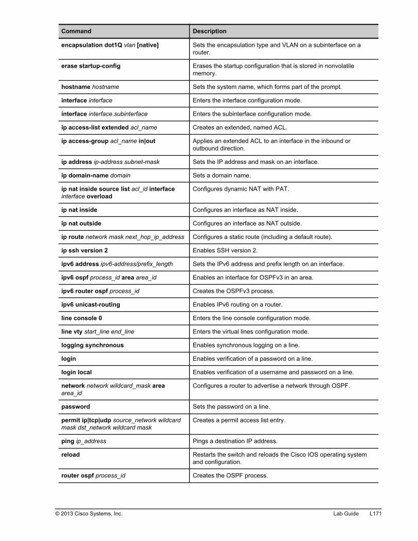
Command Description
encapsulation dot1Q vlan [native] Sets the encapsulation type and VLAN on a subinterface on arouter.
erase startup-config Erases the startup configuration that is stored in nonvolatilememory.
hostname hostname Sets the system name, which forms part of the prompt.
interface interface Enters the interface configuration mode.
interface interface.subinterface Enters the subinterface configuration mode.
ip access-list extended acl_name Creates an extended, named ACL.
ip access-group acl_name in|out Applies an extended ACL to an interface in the inbound oroutbound direction.
ip address ip-address subnet-mask Sets the IP address and mask on an interface.
ip domain-name domain Sets a domain name.
ip nat inside source list acl_id interfaceinterface overload
Configures dynamic NAT with PAT.
ip nat inside Configures an interface as NAT inside.
ip nat outside Configures an interface as NAT outside.
ip route network mask next_hop_ip_address Configures a static route (including a default route).
ip ssh version 2 Enables SSH version 2.
ipv6 address ipv6-address/prefix_length Sets the IPv6 address and prefix length on an interface.
ipv6 ospf process_id area area_id Enables an interface for OSPFv3 in an area.
ipv6 router ospf process_id Creates the OSPFv3 process.
ipv6 unicast-routing Enables IPv6 routing on a router.
line console 0 Enters the line console configuration mode.
line vty start_line end_line Enters the virtual lines configuration mode.
logging synchronous Enables synchronous logging on a line.
login Enables verification of a password on a line.
login local Enables verification of a username and password on a line.
network network wildcard_mask areaarea_id
Configures a router to advertise a network through OSPF.
password Sets the password on a line.
permit ip|tcp|udp source_network wildcardmask dst_network wildcard mask
Creates a permit access list entry.
ping ip_address Pings a destination IP address.
reload Restarts the switch and reloads the Cisco IOS operating systemand configuration.
router ospf process_id Creates the OSPF process.
© 2013 Cisco Systems, Inc. Lab Guide L171
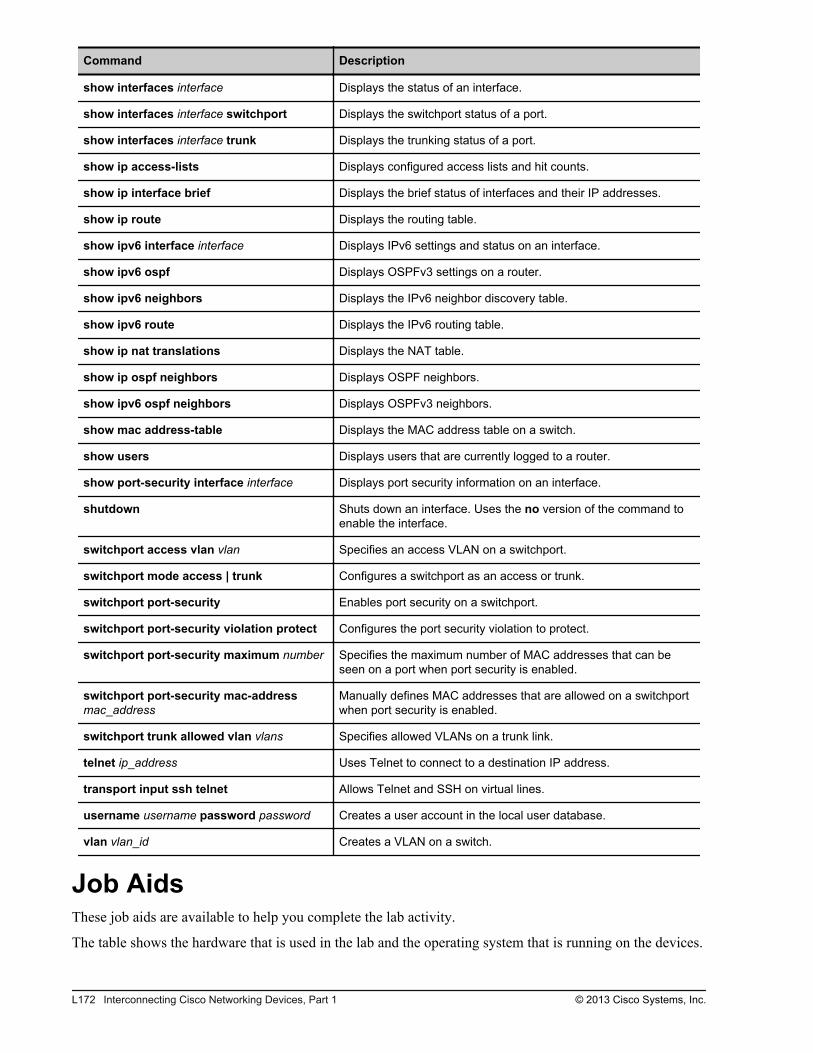
Command Description
show interfaces interface Displays the status of an interface.
show interfaces interface switchport Displays the switchport status of a port.
show interfaces interface trunk Displays the trunking status of a port.
show ip access-lists Displays configured access lists and hit counts.
show ip interface brief Displays the brief status of interfaces and their IP addresses.
show ip route Displays the routing table.
show ipv6 interface interface Displays IPv6 settings and status on an interface.
show ipv6 ospf Displays OSPFv3 settings on a router.
show ipv6 neighbors Displays the IPv6 neighbor discovery table.
show ipv6 route Displays the IPv6 routing table.
show ip nat translations Displays the NAT table.
show ip ospf neighbors Displays OSPF neighbors.
show ipv6 ospf neighbors Displays OSPFv3 neighbors.
show mac address-table Displays the MAC address table on a switch.
show users Displays users that are currently logged to a router.
show port-security interface interface Displays port security information on an interface.
shutdown Shuts down an interface. Uses the no version of the command toenable the interface.
switchport access vlan vlan Specifies an access VLAN on a switchport.
switchport mode access | trunk Configures a switchport as an access or trunk.
switchport port-security Enables port security on a switchport.
switchport port-security violation protect Configures the port security violation to protect.
switchport port-security maximum number Specifies the maximum number of MAC addresses that can beseen on a port when port security is enabled.
switchport port-security mac-addressmac_address
Manually defines MAC addresses that are allowed on a switchportwhen port security is enabled.
switchport trunk allowed vlan vlans Specifies allowed VLANs on a trunk link.
telnet ip_address Uses Telnet to connect to a destination IP address.
transport input ssh telnet Allows Telnet and SSH on virtual lines.
username username password password Creates a user account in the local user database.
vlan vlan_id Creates a VLAN on a switch.
Job AidsThese job aids are available to help you complete the lab activity.
The table shows the hardware that is used in the lab and the operating system that is running on the devices.
L172 Interconnecting Cisco Networking Devices, Part 1 © 2013 Cisco Systems, Inc.
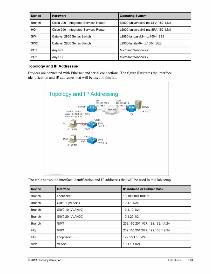
Device Hardware Operating System
Branch Cisco 2901 Integrated Services Router c2900-universalk9-mz.SPA.152-4.M1
HQ Cisco 2901 Integrated Services Router c2900-universalk9-mz.SPA.152-4.M1
SW1 Catalyst 2960 Series Switch c2960-lanbasek9-mz.150-1.SE3
SW2 Catalyst 2960 Series Switch c2960-lanlitek9-mz.150-1.SE3
PC1 Any PC Microsoft Windows 7
PC2 Any PC Microsoft Windows 7
Topology and IP Addressing
Devices are connected with Ethernet and serial connections. The figure illustrates the interfaceidentification and IP addresses that will be used in this lab.
Topology and IP Addressing
InternetServer
PC1
PC2
SW1
SW2
Branch
HQ
Fa0/1
Fa0/1
Gi0/0
Fa0/13
Fa0/3
Fa0/3
Gi0/1
209.165.201.1
192.168.1.1
Gi0/1
209.165.201.2
192.168.1.2
10.1.10.100
10.1.20.100
10.1.1.11
10.1.1.12
VLAN 1—10.1.1.1
VLAN 10—10.1.10.1
VLAN 20—10.1.20.1
172.16.1.100
© 2013 Cisco Systems, Inc.
The table shows the interface identification and IP addresses that will be used in this lab setup.
Device Interface IP Address or Subnet Mask
Branch Looback10 10.100.100.100/32
Branch Gi0/0.1 (VLAN1) 10.1.1.1/24
Branch Gi0/0.10 (VLAN10) 10.1.10.1/24
Branch Gi0/0.20 (VLAN20) 10.1.20.1/24
Branch Gi0/1 209.165.201.1/27, 192.168.1.1/24
HQ Gi0/1 209.165.201.2/27, 192.168.1.2/24
HQ Loopback0 172.16.1.100/24
SW1 VLAN1 10.1.1.11/24
© 2013 Cisco Systems, Inc. Lab Guide L173
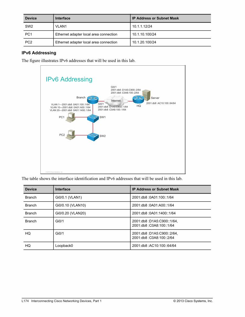
Device Interface IP Address or Subnet Mask
SW2 VLAN1 10.1.1.12/24
PC1 Ethernet adapter local area connection 10.1.10.100/24
PC2 Ethernet adapter local area connection 10.1.20.100/24
IPv6 Addressing
The figure illustrates IPv6 addresses that will be used in this lab.
IPv6 Addressing
InternetServer
PC1
PC2
SW1
SW2
Branch
HQGi0/1
2001:db8 :D1A5:C900::1/64
2001:db8 :C0A8:100::1/64
Gi0/1
2001:db8 :D1A5:C900::2/64
2001:db8 :C0A8:100::2/64
VLAN 1—2001:db8 :0A01:100::1/64
VLAN 10—2001:db8 :0A01:A00::1/64
VLAN 20—2001:db8 :0A01:1400::1/64
2001:db8 :AC10:100::64/64
© 2013 Cisco Systems, Inc.
The table shows the interface identification and IPv6 addresses that will be used in this lab.
Device Interface IP Address or Subnet Mask
Branch Gi0/0.1 (VLAN1) 2001:db8 :0A01:100::1/64
Branch Gi0/0.10 (VLAN10) 2001:db8 :0A01:A00::1/64
Branch Gi0/0.20 (VLAN20) 2001:db8 :0A01:1400::1/64
Branch Gi0/1 2001:db8 :D1A5:C900::1/64,2001:db8 :C0A8:100::1/64
HQ Gi0/1 2001:db8 :D1A5:C900::2/64,2001:db8 :C0A8:100::2/64
HQ Loopback0 2001:db8 :AC10:100::64/64
L174 Interconnecting Cisco Networking Devices, Part 1 © 2013 Cisco Systems, Inc.
Task 1: Configure Basic Settings, VLANs, Trunks,and Port Security on SwitchesIn this task, you will first delete the existing configuration from SW1 and SW2 switches and reload them.Then you will configure basic settings on the switches and secure administrative access to the switches.You will also configure VLANs and trunks on the switches and put both PCs into different VLANs. Finally,you will enable port security on the switches to prevent unauthorized access to the LAN.
Activity ProcedureComplete the following steps:
Step 1
Access the SW1 and SW2 switches.
Step 2
Delete the startup configuration from the SW1 and SW2 switches. Delete the vlan.dat file from the flashmemory of the switches and delete the VLAN information. Reload the switches in order to boot theswitches with an empty configuration.
Step 3
Configure a hostname (SW1, SW2) on the switches.
Step 4
Configure IPv4 addresses on both switches for management purposes. Assign the IP address to the VLAN 1interface. Use the Job Aids section of the document to determine the IP address for each switch. Enable theVLAN 1 interface.
Step 5
Configure the enable password on the SW1 and SW2 switches. Use the command that will store theconfigured password in encrypted form. Use cisco as a password.
Step 6
Secure console access to the switches by enabling the password on the console. Use cisco as a password.Enable synchronous logging on the console to make the input of commands easier.
Step 7
Enable SSH version 2 remote access to the SW1 and SW2 switches. Use 1024-bit long RSA keys andcisco.com as the domain name. Allow Telnet and SSH on the virtual lines.
© 2013 Cisco Systems, Inc. Lab Guide L175
Step 8
Create a local user account on the switches that will be used to authenticate users accessing the switches viaSSH or Telnet. Use ccna as a username and cisco as a password. Configure the virtual lines for checkingthe username and password.
Step 9
Create two additional VLANs on the switches. Use VLAN 10 and 20.
Step 10
Configure a trunk between SW1 and SW2 switches over the FastEthernet0/3 port. Allow only VLANs 1,10, and 20 on the trunk link. Shut down the FastEthernet0/4 port on both switches.
Step 11
On SW1, configure the port connecting to PC1 (FastEthernet0/1) as the access port. Put the port into VLAN10.
Step 12
On SW2, configure the port connecting to PC2 (FastEthernet0/1) as the access port. Put the port into VLAN20.
L176 Interconnecting Cisco Networking Devices, Part 1 © 2013 Cisco Systems, Inc.
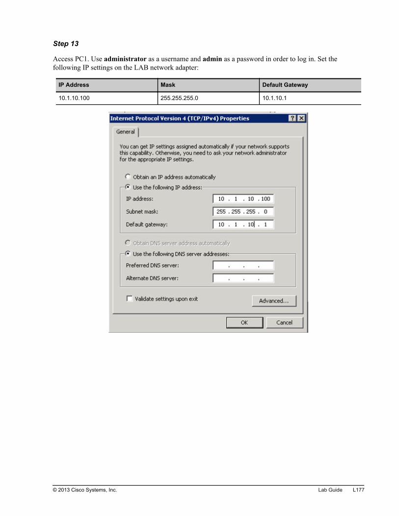
Step 13
Access PC1. Use administrator as a username and admin as a password in order to log in. Set thefollowing IP settings on the LAB network adapter:
IP Address Mask Default Gateway
10.1.10.100 255.255.255.0 10.1.10.1
© 2013 Cisco Systems, Inc. Lab Guide L177
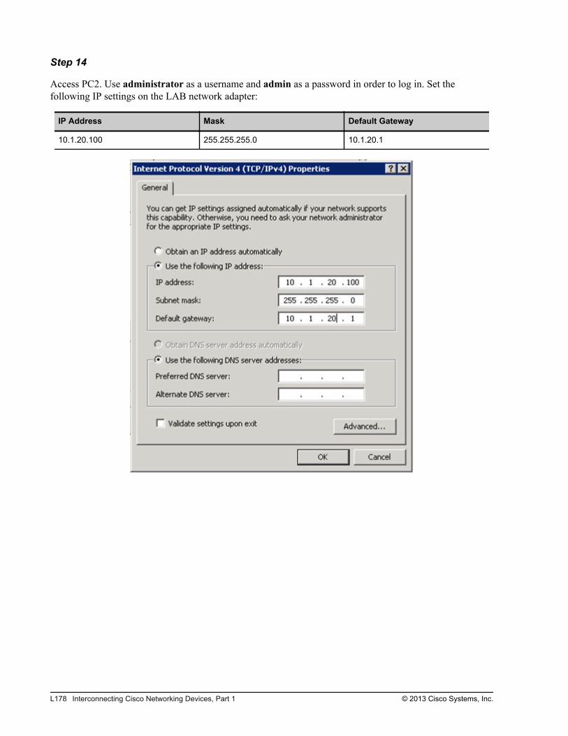
Step 14
Access PC2. Use administrator as a username and admin as a password in order to log in. Set thefollowing IP settings on the LAB network adapter:
IP Address Mask Default Gateway
10.1.20.100 255.255.255.0 10.1.20.1
L178 Interconnecting Cisco Networking Devices, Part 1 © 2013 Cisco Systems, Inc.
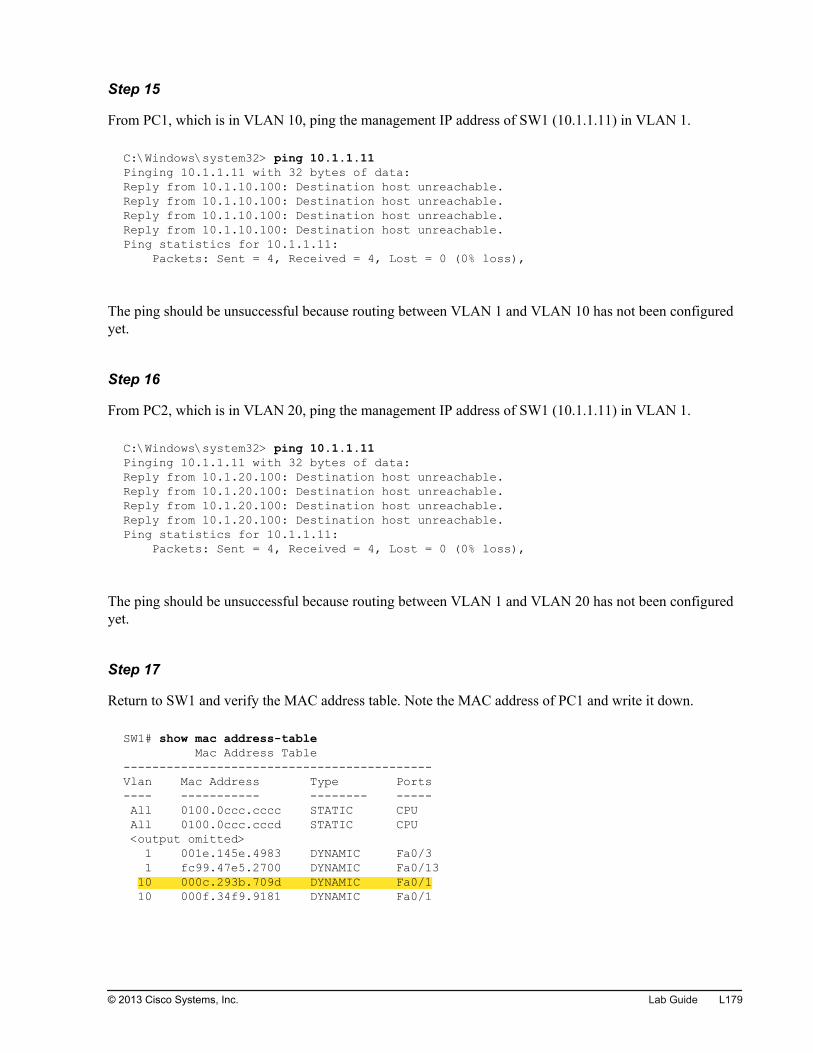
Step 15
From PC1, which is in VLAN 10, ping the management IP address of SW1 (10.1.1.11) in VLAN 1.
C:\Windows\system32> ping 10.1.1.11Pinging 10.1.1.11 with 32 bytes of data:Reply from 10.1.10.100: Destination host unreachable.Reply from 10.1.10.100: Destination host unreachable.Reply from 10.1.10.100: Destination host unreachable.Reply from 10.1.10.100: Destination host unreachable.Ping statistics for 10.1.1.11: Packets: Sent = 4, Received = 4, Lost = 0 (0% loss),
The ping should be unsuccessful because routing between VLAN 1 and VLAN 10 has not been configuredyet.
Step 16
From PC2, which is in VLAN 20, ping the management IP address of SW1 (10.1.1.11) in VLAN 1.
C:\Windows\system32> ping 10.1.1.11Pinging 10.1.1.11 with 32 bytes of data:Reply from 10.1.20.100: Destination host unreachable.Reply from 10.1.20.100: Destination host unreachable.Reply from 10.1.20.100: Destination host unreachable.Reply from 10.1.20.100: Destination host unreachable.Ping statistics for 10.1.1.11: Packets: Sent = 4, Received = 4, Lost = 0 (0% loss),
The ping should be unsuccessful because routing between VLAN 1 and VLAN 20 has not been configuredyet.
Step 17
Return to SW1 and verify the MAC address table. Note the MAC address of PC1 and write it down.
SW1# show mac address-table Mac Address Table-------------------------------------------Vlan Mac Address Type Ports---- ----------- -------- ----- All 0100.0ccc.cccc STATIC CPU All 0100.0ccc.cccd STATIC CPU <output omitted> 1 001e.145e.4983 DYNAMIC Fa0/3 1 fc99.47e5.2700 DYNAMIC Fa0/13 10 000c.293b.709d DYNAMIC Fa0/1 10 000f.34f9.9181 DYNAMIC Fa0/1
© 2013 Cisco Systems, Inc. Lab Guide L179
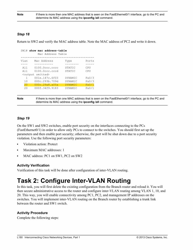
Note If there is more then one MAC address that is seen on the FastEthernet0/1 interface, go to the PC anddetermine its MAC address using the ipconfig /all command.
Step 18
Return to SW2 and verify the MAC address table. Note the MAC address of PC2 and write it down.
SW1# show mac address-table Mac Address Table-------------------------------------------Vlan Mac Address Type Ports---- ----------- -------- ----- All 0100.0ccc.cccc STATIC CPU All 0100.0ccc.cccd STATIC CPU <output omitted> 1 001e.147c.6f03 DYNAMIC Fa0/3 10 000c.293b.709d DYNAMIC Fa0/3 20 000c.29a8.a05a DYNAMIC Fa0/1 20 000f.34f9.9183 DYNAMIC Fa0/1
Note If there is more than one MAC address that is seen on the FastEthernet0/1 interface, go to the PC anddetermine its MAC address using the ipconfig /all command.
Step 19
On the SW1 and SW2 switches, enable port security on the interfaces connecting to the PCs(FastEthernet0/1) in order to allow only PCs to connect to the switches. You should first set up theparameters and then enable port security; otherwise, the port will be shut down due to a port securityviolation. Use the following port security parameters:
Violation action: Protect
Maximum MAC addresses: 1
MAC address: PC1 on SW1, PC2 on SW2
Activity VerificationVerification of this task will be done after configuration of inter-VLAN routing.
Task 2: Configure Inter-VLAN RoutingIn this task, you will first delete the existing configuration from the Branch router and reload it. You willthen secure administrative access to the router and configure inter-VLAN routing among VLAN 1, 10, and20. This way, you will enable connectivity among PC1, PC2, and management IP addresses on theswitches. You will implement inter-VLAN routing on the Branch router by establishing a trunk linkbetween the router and SW1 switch.
Activity ProcedureComplete the following steps:
L180 Interconnecting Cisco Networking Devices, Part 1 © 2013 Cisco Systems, Inc.
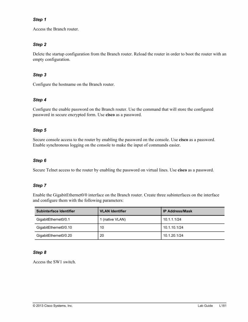
Step 1
Access the Branch router.
Step 2
Delete the startup configuration from the Branch router. Reload the router in order to boot the router with anempty configuration.
Step 3
Configure the hostname on the Branch router.
Step 4
Configure the enable password on the Branch router. Use the command that will store the configuredpassword in secure encrypted form. Use cisco as a password.
Step 5
Secure console access to the router by enabling the password on the console. Use cisco as a password.Enable synchronous logging on the console to make the input of commands easier.
Step 6
Secure Telnet access to the router by enabling the password on virtual lines. Use cisco as a password.
Step 7
Enable the GigabitEthernet0/0 interface on the Branch router. Create three subinterfaces on the interfaceand configure them with the following parameters:
Subinterface Identifier VLAN Identifier IP Address/Mask
GigabitEthernet0/0.1 1 (native VLAN) 10.1.1.1/24
GigabitEthernet0/0.10 10 10.1.10.1/24
GigabitEthernet0/0.20 20 10.1.20.1/24
Step 8
Access the SW1 switch.
© 2013 Cisco Systems, Inc. Lab Guide L181
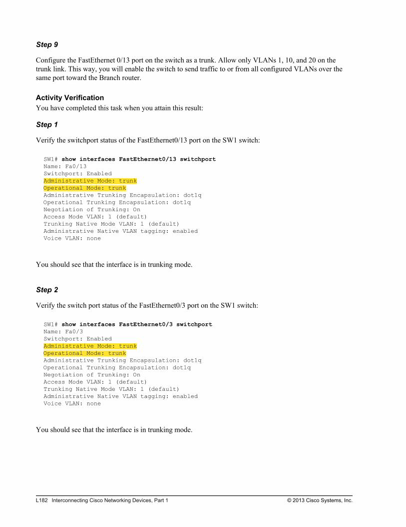
Step 9
Configure the FastEthernet 0/13 port on the switch as a trunk. Allow only VLANs 1, 10, and 20 on thetrunk link. This way, you will enable the switch to send traffic to or from all configured VLANs over thesame port toward the Branch router.
Activity VerificationYou have completed this task when you attain this result:
Step 1
Verify the switchport status of the FastEthernet0/13 port on the SW1 switch:
SW1# show interfaces FastEthernet0/13 switchport Name: Fa0/13Switchport: EnabledAdministrative Mode: trunkOperational Mode: trunkAdministrative Trunking Encapsulation: dot1qOperational Trunking Encapsulation: dot1qNegotiation of Trunking: OnAccess Mode VLAN: 1 (default)Trunking Native Mode VLAN: 1 (default)Administrative Native VLAN tagging: enabledVoice VLAN: none
You should see that the interface is in trunking mode.
Step 2
Verify the switch port status of the FastEthernet0/3 port on the SW1 switch:
SW1# show interfaces FastEthernet0/3 switchport Name: Fa0/3Switchport: EnabledAdministrative Mode: trunkOperational Mode: trunkAdministrative Trunking Encapsulation: dot1qOperational Trunking Encapsulation: dot1qNegotiation of Trunking: OnAccess Mode VLAN: 1 (default)Trunking Native Mode VLAN: 1 (default)Administrative Native VLAN tagging: enabledVoice VLAN: none
You should see that the interface is in trunking mode.
L182 Interconnecting Cisco Networking Devices, Part 1 © 2013 Cisco Systems, Inc.

Step 3
Verify the trunking status of the FastEthernet0/3 port on the SW1 switch:
SW1# show interfaces FastEthernet0/3 trunk Port Mode Encapsulation Status Native vlanFa0/3 on 802.1q trunking 1Port Vlans allowed on trunkFa0/3 1,10,20Port Vlans allowed and active in management domainFa0/3 1,10,20Port Vlans in spanning tree forwarding state and not prunedFa0/3 1,10,20
You should see that the interface is in trunking mode, encapsulation is 802.1q, and VLANs 1, 10, and 20are active and not pruned.
Step 4
Verify the trunking status of the FastEthernet0/3 port on the SW2 switch:
SW2# show interfaces FastEthernet0/3 trunk Port Mode Encapsulation Status Native vlanFa0/3 on 802.1q trunking 1Port Vlans allowed on trunkFa0/3 1,10,20Port Vlans allowed and active in management domainFa0/3 1,10,20Port Vlans in spanning tree forwarding state and not prunedFa0/3 1,10,20
You should see that the interface is in trunking mode, encapsulation is 802.1q, and VLANs 1, 10, and 20are active and not pruned.
Step 5
On the Branch router, verify the state of configured subinterfaces:
Branch# show ip interface brief Interface IP-Address OK? Method Status ProtocolEmbedded-Service-Engine0/0 unassigned YES unset administratively down down GigabitEthernet0/0 unassigned YES unset up up GigabitEthernet0/0.1 10.1.1.1 YES manual up up GigabitEthernet0/0.10 10.1.10.1 YES manual up up GigabitEthernet0/0.20 10.1.20.1 YES manual up up <output omitted>
You should see that the subinterfaces are configured with IP addresses and are operational.
© 2013 Cisco Systems, Inc. Lab Guide L183

Step 6
Access PC1. Ping the SW1 management IP address at 10.1.1.11.
C:\Windows\system32> ping 10.1.1.11Pinging 10.1.1.11 with 32 bytes of data:Request timed out.Reply from 10.1.1.11: bytes=32 time=8ms TTL=254Reply from 10.1.1.11: bytes=32 time=2ms TTL=254Reply from 10.1.1.11: bytes=32 time=2ms TTL=254Ping statistics for 10.1.1.11: Packets: Sent = 4, Received = 3, Lost = 1 (25% loss),Approximate round trip times in milli-seconds: Minimum = 2ms, Maximum = 8ms, Average = 4ms
The ping should be successful.
Step 7
Ping PC2 at 10.1.20.100 from PC1.
C:\Windows\system32> ping 10.1.20.100Pinging 10.1.20.100 with 32 bytes of data:Reply from 10.1.20.100: bytes=32 time=15ms TTL=127Reply from 10.1.20.100: bytes=32 time=1ms TTL=127Reply from 10.1.20.100: bytes=32 time=1ms TTL=127Reply from 10.1.20.100: bytes=32 time=1ms TTL=127Ping statistics for 10.1.20.100: Packets: Sent = 4, Received = 4, Lost = 0 (0% loss),Approximate round trip times in milli-seconds: Minimum = 1ms, Maximum = 15ms, Average = 4ms
The ping should be successful.
L184 Interconnecting Cisco Networking Devices, Part 1 © 2013 Cisco Systems, Inc.
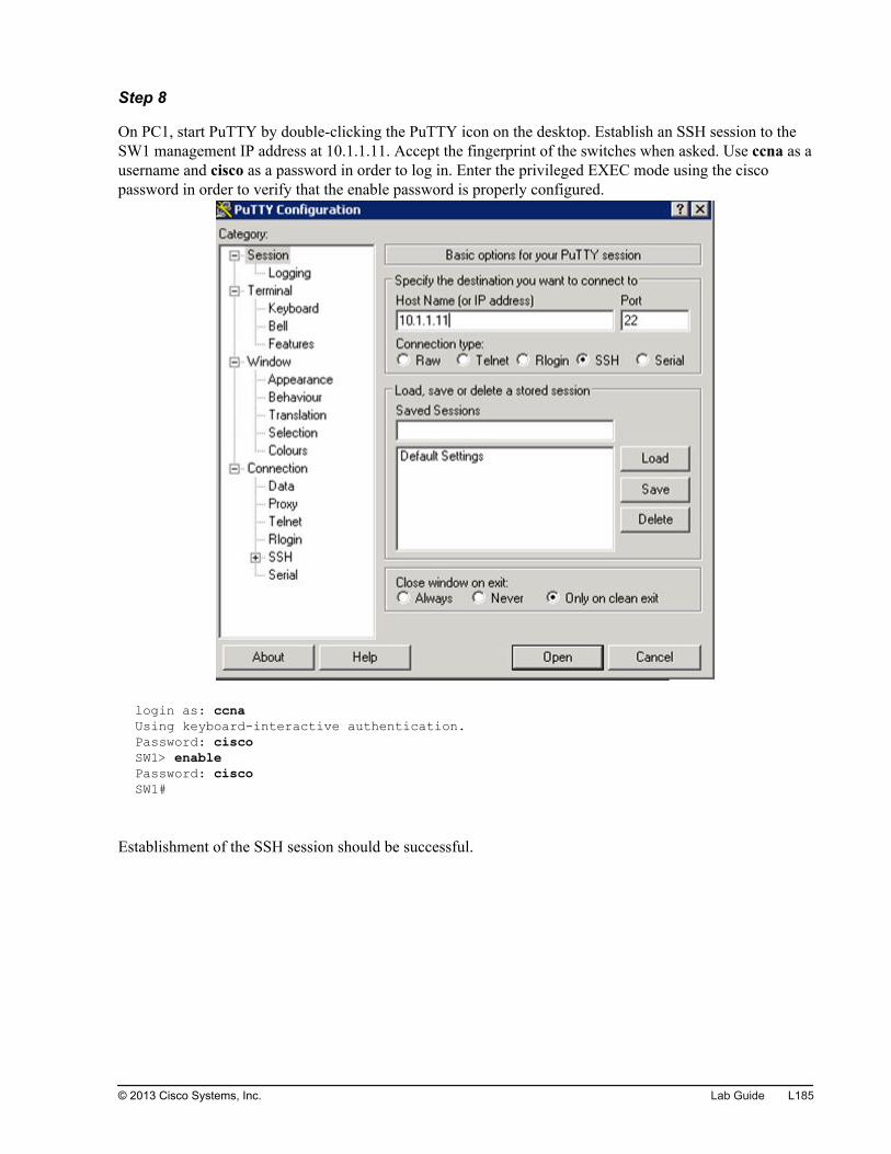
Step 8
On PC1, start PuTTY by double-clicking the PuTTY icon on the desktop. Establish an SSH session to theSW1 management IP address at 10.1.1.11. Accept the fingerprint of the switches when asked. Use ccna as ausername and cisco as a password in order to log in. Enter the privileged EXEC mode using the ciscopassword in order to verify that the enable password is properly configured.
login as: ccnaUsing keyboard-interactive authentication.Password: ciscoSW1> enablePassword: ciscoSW1#
Establishment of the SSH session should be successful.
© 2013 Cisco Systems, Inc. Lab Guide L185
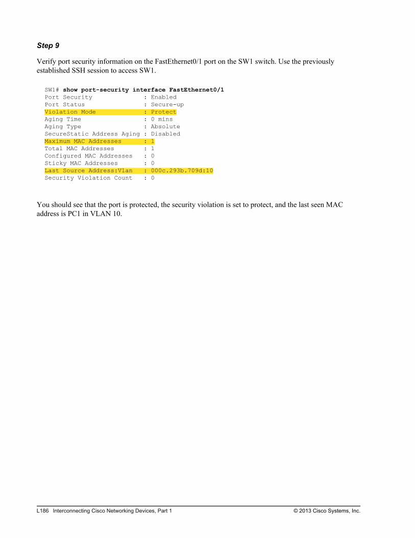
Step 9
Verify port security information on the FastEthernet0/1 port on the SW1 switch. Use the previouslyestablished SSH session to access SW1.
SW1# show port-security interface FastEthernet0/1Port Security : EnabledPort Status : Secure-upViolation Mode : ProtectAging Time : 0 minsAging Type : AbsoluteSecureStatic Address Aging : DisabledMaximum MAC Addresses : 1Total MAC Addresses : 1Configured MAC Addresses : 0Sticky MAC Addresses : 0Last Source Address:Vlan : 000c.293b.709d:10Security Violation Count : 0
You should see that the port is protected, the security violation is set to protect, and the last seen MACaddress is PC1 in VLAN 10.
L186 Interconnecting Cisco Networking Devices, Part 1 © 2013 Cisco Systems, Inc.
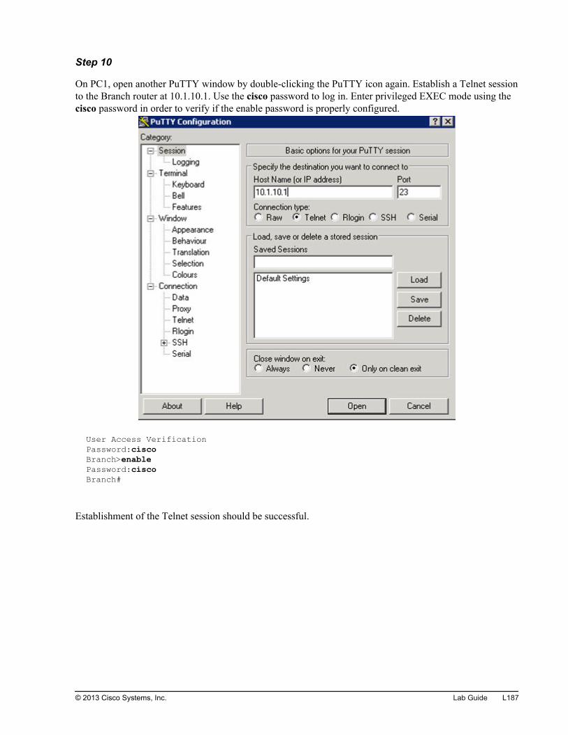
Step 10
On PC1, open another PuTTY window by double-clicking the PuTTY icon again. Establish a Telnet sessionto the Branch router at 10.1.10.1. Use the cisco password to log in. Enter privileged EXEC mode using thecisco password in order to verify if the enable password is properly configured.
User Access VerificationPassword:ciscoBranch>enablePassword:ciscoBranch#
Establishment of the Telnet session should be successful.
© 2013 Cisco Systems, Inc. Lab Guide L187
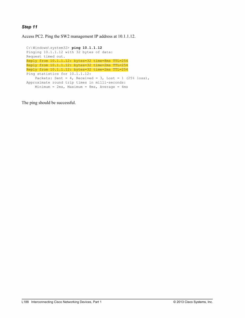
Step 11
Access PC2. Ping the SW2 management IP address at 10.1.1.12.
C:\Windows\system32> ping 10.1.1.12Pinging 10.1.1.12 with 32 bytes of data:Request timed out.Reply from 10.1.1.12: bytes=32 time=8ms TTL=254Reply from 10.1.1.12: bytes=32 time=2ms TTL=254Reply from 10.1.1.12: bytes=32 time=2ms TTL=254Ping statistics for 10.1.1.12: Packets: Sent = 4, Received = 3, Lost = 1 (25% loss),Approximate round trip times in milli-seconds: Minimum = 2ms, Maximum = 8ms, Average = 4ms
The ping should be successful.
L188 Interconnecting Cisco Networking Devices, Part 1 © 2013 Cisco Systems, Inc.
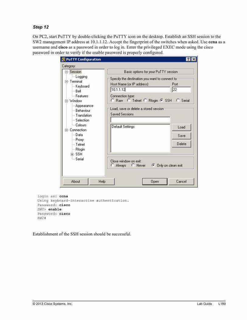
Step 12
On PC2, start PuTTY by double-clicking the PuTTY icon on the desktop. Establish an SSH session to theSW2 management IP address at 10.1.1.12. Accept the fingerprint of the switches when asked. Use ccna as ausername and cisco as a password in order to log in. Enter the privileged EXEC mode using the ciscopassword in order to verify if the enable password is properly configured.
login as: ccnaUsing keyboard-interactive authentication.Password: ciscoSW2> enablePassword: ciscoSW2#
Establishment of the SSH session should be successful.
© 2013 Cisco Systems, Inc. Lab Guide L189

Step 13
Verify port security information on the FastEthernet0/1 port on the SW2 switch. Use the previouslyestablished SSH session to access SW2.
SW2# show port-security interface FastEthernet0/1Port Security : EnabledPort Status : Secure-upViolation Mode : ProtectAging Time : 0 minsAging Type : AbsoluteSecureStatic Address Aging : DisabledMaximum MAC Addresses : 1Total MAC Addresses : 1Configured MAC Addresses : 1Sticky MAC Addresses : 0Last Source Address:Vlan : 000f.34f9.9183:20Security Violation Count : 0
You should see that the port is protected, the security violation is set to protect, and the last seen MACaddress is PC2 in VLAN 20.
Step 14
Close all SSH and Telnet sessions on PC1 and PC2.
Task 3: Configure Internet ConnectivityIn this task, you will configure the Branch router to provide Internet connectivity. This includes configuringIP addresses on an interface and default route. You will also configure NAT with PAT to hide internaladdressing from the Internet. Finally, you will configure an ACL that will protect the router and LAN fromtraffic on the Internet.
Activity ProcedureComplete the following steps:
Step 1
Access the Branch router.
Step 2
Configure an IP address on the Branch router on the interface connecting to the Internet(GigabitEthernet0/1). Use 209.165.201.1/27 for the IP address. Enable the interface.
Step 3
Configure a default route on the Branch router that will point to the HQ router as the next hop.
L190 Interconnecting Cisco Networking Devices, Part 1 © 2013 Cisco Systems, Inc.
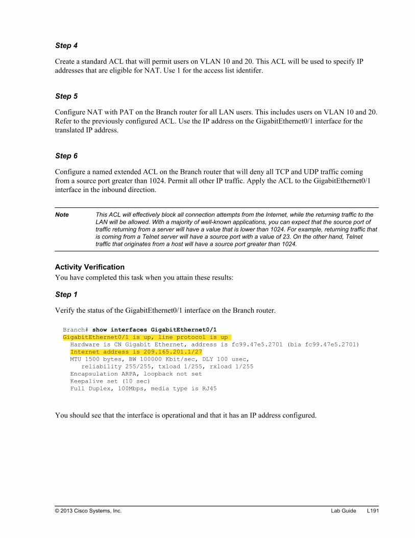
Step 4
Create a standard ACL that will permit users on VLAN 10 and 20. This ACL will be used to specify IPaddresses that are eligible for NAT. Use 1 for the access list identifer.
Step 5
Configure NAT with PAT on the Branch router for all LAN users. This includes users on VLAN 10 and 20.Refer to the previously configured ACL. Use the IP address on the GigabitEthernet0/1 interface for thetranslated IP address.
Step 6
Configure a named extended ACL on the Branch router that will deny all TCP and UDP traffic comingfrom a source port greater than 1024. Permit all other IP traffic. Apply the ACL to the GigabitEthernet0/1interface in the inbound direction.
Note This ACL will effectively block all connection attempts from the Internet, while the returning traffic to theLAN will be allowed. With a majority of well-known applications, you can expect that the source port oftraffic returning from a server will have a value that is lower than 1024. For example, returning traffic thatis coming from a Telnet server will have a source port with a value of 23. On the other hand, Telnettraffic that originates from a host will have a source port greater than 1024.
Activity VerificationYou have completed this task when you attain these results:
Step 1
Verify the status of the GigabitEthernet0/1 interface on the Branch router.
Branch# show interfaces GigabitEthernet0/1GigabitEthernet0/1 is up, line protocol is up Hardware is CN Gigabit Ethernet, address is fc99.47e5.2701 (bia fc99.47e5.2701) Internet address is 209.165.201.1/27 MTU 1500 bytes, BW 100000 Kbit/sec, DLY 100 usec, reliability 255/255, txload 1/255, rxload 1/255 Encapsulation ARPA, loopback not set Keepalive set (10 sec) Full Duplex, 100Mbps, media type is RJ45
You should see that the interface is operational and that it has an IP address configured.
© 2013 Cisco Systems, Inc. Lab Guide L191
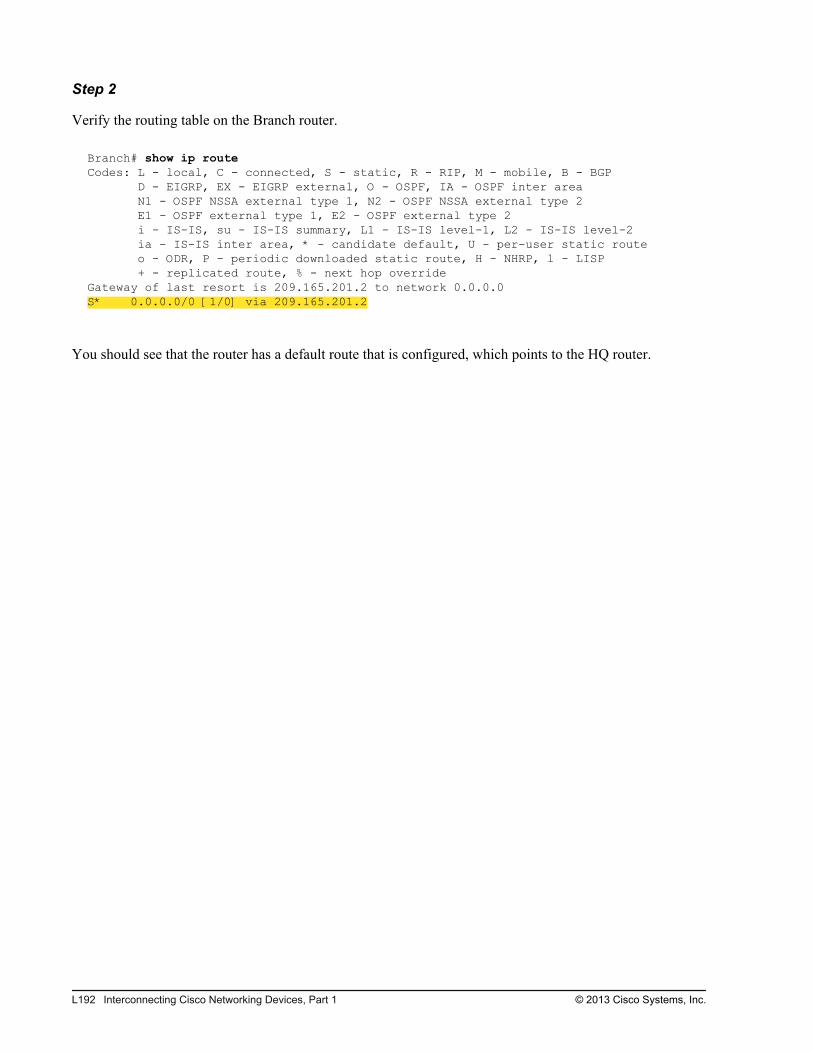
Step 2
Verify the routing table on the Branch router.
Branch# show ip routeCodes: L - local, C - connected, S - static, R - RIP, M - mobile, B - BGP D - EIGRP, EX - EIGRP external, O - OSPF, IA - OSPF inter area N1 - OSPF NSSA external type 1, N2 - OSPF NSSA external type 2 E1 - OSPF external type 1, E2 - OSPF external type 2 i - IS-IS, su - IS-IS summary, L1 - IS-IS level-1, L2 - IS-IS level-2 ia - IS-IS inter area, * - candidate default, U - per-user static route o - ODR, P - periodic downloaded static route, H - NHRP, l - LISP + - replicated route, % - next hop overrideGateway of last resort is 209.165.201.2 to network 0.0.0.0S* 0.0.0.0/0 [1/0] via 209.165.201.2
You should see that the router has a default route that is configured, which points to the HQ router.
L192 Interconnecting Cisco Networking Devices, Part 1 © 2013 Cisco Systems, Inc.
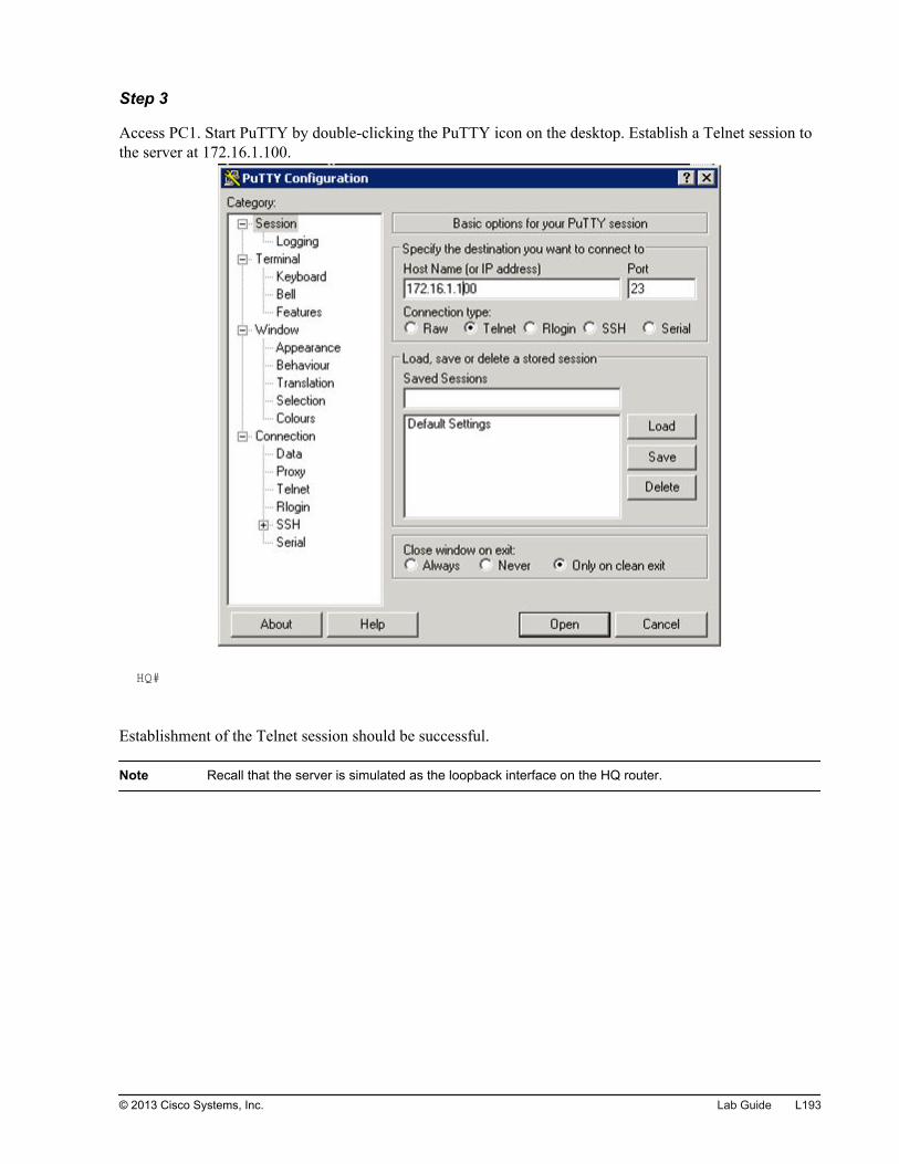
Step 3
Access PC1. Start PuTTY by double-clicking the PuTTY icon on the desktop. Establish a Telnet session tothe server at 172.16.1.100.
HQ#
Establishment of the Telnet session should be successful.
Note Recall that the server is simulated as the loopback interface on the HQ router.
© 2013 Cisco Systems, Inc. Lab Guide L193
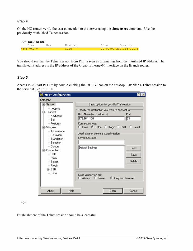
Step 4
On the HQ router, verify the user connection to the server using the show users command. Use thepreviously established Telnet session.
HQ# show users Line User Host(s) Idle Location*388 vty 0 idle 00:00:00 209.165.201.1
You should see that the Telnet session from PC1 is seen as originating from the translated IP address. Thetranslated IP address is the IP address of the GigabitEthernet0/1 interface on the Branch router.
Step 5
Access PC2. Start PuTTY by double-clicking the PuTTY icon on the desktop. Establish a Telnet session tothe server at 172.16.1.100.
HQ#
Establishment of the Telnet session should be successful.
L194 Interconnecting Cisco Networking Devices, Part 1 © 2013 Cisco Systems, Inc.
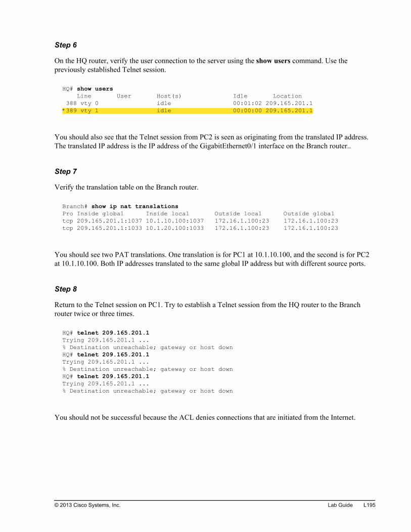
Step 6
On the HQ router, verify the user connection to the server using the show users command. Use thepreviously established Telnet session.
HQ# show users Line User Host(s) Idle Location 388 vty 0 idle 00:01:02 209.165.201.1*389 vty 1 idle 00:00:00 209.165.201.1
You should also see that the Telnet session from PC2 is seen as originating from the translated IP address.The translated IP address is the IP address of the GigabitEthernet0/1 interface on the Branch router..
Step 7
Verify the translation table on the Branch router.
Branch# show ip nat translations Pro Inside global Inside local Outside local Outside globaltcp 209.165.201.1:1037 10.1.10.100:1037 172.16.1.100:23 172.16.1.100:23tcp 209.165.201.1:1033 10.1.20.100:1033 172.16.1.100:23 172.16.1.100:23
You should see two PAT translations. One translation is for PC1 at 10.1.10.100, and the second is for PC2at 10.1.10.100. Both IP addresses translated to the same global IP address but with different source ports.
Step 8
Return to the Telnet session on PC1. Try to establish a Telnet session from the HQ router to the Branchrouter twice or three times.
HQ# telnet 209.165.201.1Trying 209.165.201.1 ...% Destination unreachable; gateway or host downHQ# telnet 209.165.201.1Trying 209.165.201.1 ...% Destination unreachable; gateway or host downHQ# telnet 209.165.201.1Trying 209.165.201.1 ...% Destination unreachable; gateway or host down
You should not be successful because the ACL denies connections that are initiated from the Internet.
© 2013 Cisco Systems, Inc. Lab Guide L195
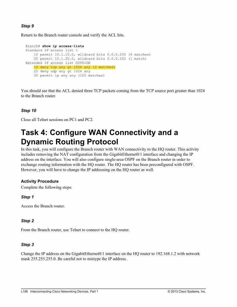
Step 9
Return to the Branch router console and verify the ACL hits.
Branch# show ip access-lists Standard IP access list 1 10 permit 10.1.10.0, wildcard bits 0.0.0.255 (4 matches) 20 permit 10.1.20.0, wildcard bits 0.0.0.255 (1 match)Extended IP access list OUTSIDE 10 deny tcp any gt 1024 any (3 matches) 20 deny udp any gt 1024 any 30 permit ip any any (122 matches)
You should see that the ACL denied three TCP packets coming from the TCP source port greater than 1024to the Branch router.
Step 10
Close all Telnet sessions on PC1 and PC2.
Task 4: Configure WAN Connectivity and aDynamic Routing ProtocolIn this task, you will configure the Branch router with WAN connectivity to the HQ router. This activityincludes removing the NAT configuration from the GigabitEthernet0/1 interface and changing the IPaddress on the interface. You will also configure single-area OSPF on the Branch router in order toexchange routing information with the HQ router. The HQ router has been preconfigured with OSPF.However, you will have to change the IP addressing on the HQ router as well.
Activity ProcedureComplete the following steps:
Step 1
Access the Branch router.
Step 2
From the Branch router, use Telnet to connect to the HQ router.
Step 3
Change the IP address on the GigabitEthernet0/1 interface on the HQ router to 192.168.1.2 with networkmask 255.255.255.0. Be careful not to mistype the IP address.
L196 Interconnecting Cisco Networking Devices, Part 1 © 2013 Cisco Systems, Inc.

Note Changing the IP address on the HQ router will terminate your Telnet session. If the session freezes,press Ctrl-Shift-6, followed by X. This action will pause the Telnet session, and you will return to theBranch router console. At the Branch router prompt, enter Disconnect to disconnect the frozen Telnetsession permanently.
Step 4
On the Branch router, remove the NAT configuration from the GigabitEthernet0/1 interface.
Step 5
Configure the IP address on the Branch router on the GigabitEthernet0/1 interface. Use 192.168.1.1/24 forthe IP address.
Step 6
Configure a loopback interface on the Branch router. Use 10 as the interface ID and 10.100.100.100/32 asthe IP address.
Why is it recommended to configure a loopback interface when enabling an OSPF routing protocol?
Step 7
Create the OSPF routing process on the Branch router. Use 1 as the OSPF process ID.
Step 8
Enable OSPF routing in Area 0 for the following networks:
192.168.1.0/24
10.1.1.0/24
10.1.10.0/24
10.1.20.0/24
10.100.100.100/32
Activity VerificationYou have completed this task when you attain these results:
© 2013 Cisco Systems, Inc. Lab Guide L197
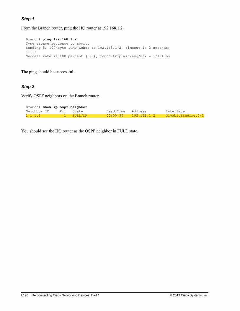
Step 1
From the Branch router, ping the HQ router at 192.168.1.2.
Branch# ping 192.168.1.2Type escape sequence to abort.Sending 5, 100-byte ICMP Echos to 192.168.1.2, timeout is 2 seconds:!!!!!Success rate is 100 percent (5/5), round-trip min/avg/max = 1/1/4 ms
The ping should be successful.
Step 2
Verify OSPF neighbors on the Branch router.
Branch# show ip ospf neighbor Neighbor ID Pri State Dead Time Address Interface1.1.1.1 1 FULL/DR 00:00:35 192.168.1.2 GigabitEthernet0/1
You should see the HQ router as the OSPF neighbor in FULL state.
L198 Interconnecting Cisco Networking Devices, Part 1 © 2013 Cisco Systems, Inc.
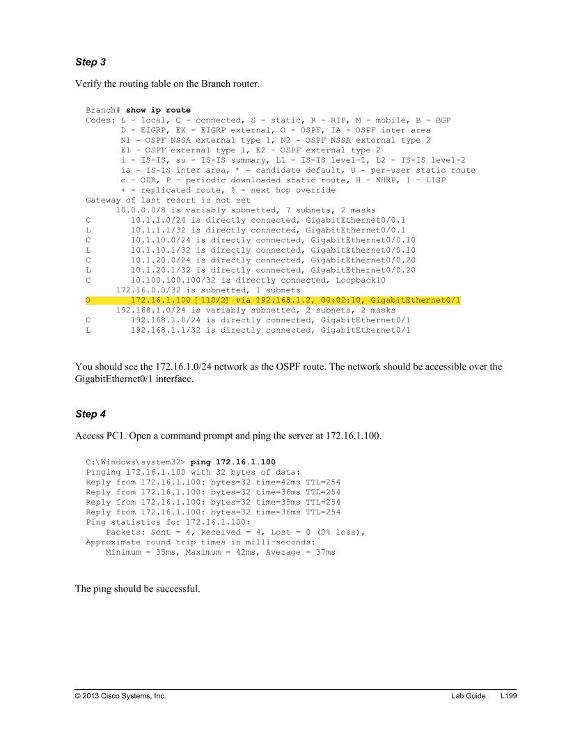
Step 3
Verify the routing table on the Branch router.
Branch# show ip route Codes: L - local, C - connected, S - static, R - RIP, M - mobile, B - BGP D - EIGRP, EX - EIGRP external, O - OSPF, IA - OSPF inter area N1 - OSPF NSSA external type 1, N2 - OSPF NSSA external type 2 E1 - OSPF external type 1, E2 - OSPF external type 2 i - IS-IS, su - IS-IS summary, L1 - IS-IS level-1, L2 - IS-IS level-2 ia - IS-IS inter area, * - candidate default, U - per-user static route o - ODR, P - periodic downloaded static route, H - NHRP, l - LISP + - replicated route, % - next hop overrideGateway of last resort is not set 10.0.0.0/8 is variably subnetted, 7 subnets, 2 masksC 10.1.1.0/24 is directly connected, GigabitEthernet0/0.1L 10.1.1.1/32 is directly connected, GigabitEthernet0/0.1C 10.1.10.0/24 is directly connected, GigabitEthernet0/0.10L 10.1.10.1/32 is directly connected, GigabitEthernet0/0.10C 10.1.20.0/24 is directly connected, GigabitEthernet0/0.20L 10.1.20.1/32 is directly connected, GigabitEthernet0/0.20C 10.100.100.100/32 is directly connected, Loopback10 172.16.0.0/32 is subnetted, 1 subnetsO 172.16.1.100 [110/2] via 192.168.1.2, 00:02:10, GigabitEthernet0/1 192.168.1.0/24 is variably subnetted, 2 subnets, 2 masksC 192.168.1.0/24 is directly connected, GigabitEthernet0/1L 192.168.1.1/32 is directly connected, GigabitEthernet0/1
You should see the 172.16.1.0/24 network as the OSPF route. The network should be accessible over theGigabitEthernet0/1 interface.
Step 4
Access PC1. Open a command prompt and ping the server at 172.16.1.100.
C:\Windows\system32> ping 172.16.1.100Pinging 172.16.1.100 with 32 bytes of data:Reply from 172.16.1.100: bytes=32 time=42ms TTL=254Reply from 172.16.1.100: bytes=32 time=36ms TTL=254Reply from 172.16.1.100: bytes=32 time=35ms TTL=254Reply from 172.16.1.100: bytes=32 time=36ms TTL=254Ping statistics for 172.16.1.100: Packets: Sent = 4, Received = 4, Lost = 0 (0% loss),Approximate round trip times in milli-seconds: Minimum = 35ms, Maximum = 42ms, Average = 37ms
The ping should be successful.
© 2013 Cisco Systems, Inc. Lab Guide L199
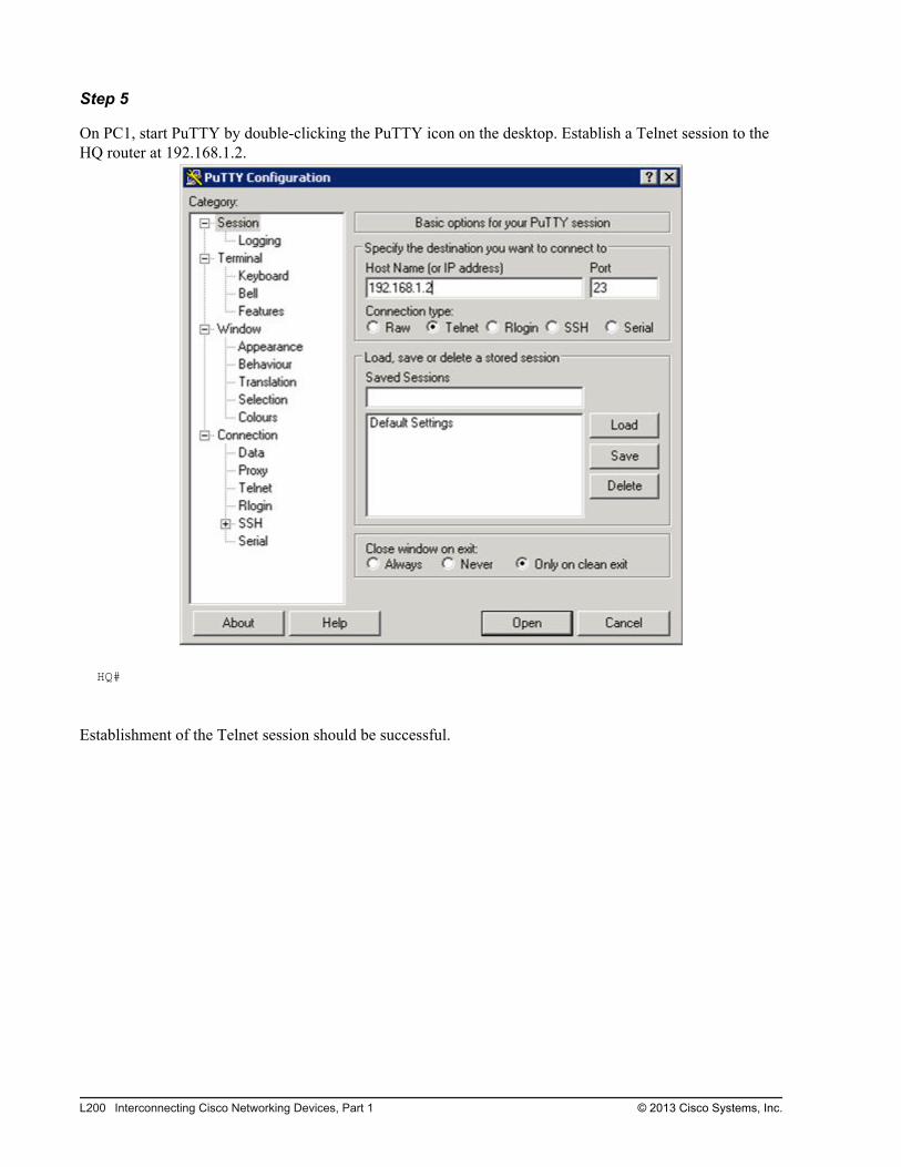
Step 5
On PC1, start PuTTY by double-clicking the PuTTY icon on the desktop. Establish a Telnet session to theHQ router at 192.168.1.2.
HQ#
Establishment of the Telnet session should be successful.
L200 Interconnecting Cisco Networking Devices, Part 1 © 2013 Cisco Systems, Inc.
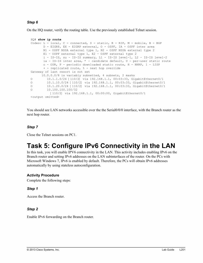
Step 6
On the HQ router, verify the routing table. Use the previously established Telnet session.
HQ# show ip route Codes: L - local, C - connected, S - static, R - RIP, M - mobile, B - BGP D - EIGRP, EX - EIGRP external, O - OSPF, IA - OSPF inter area N1 - OSPF NSSA external type 1, N2 - OSPF NSSA external type 2 E1 - OSPF external type 1, E2 - OSPF external type 2 i - IS-IS, su - IS-IS summary, L1 - IS-IS level-1, L2 - IS-IS level-2 ia - IS-IS inter area, * - candidate default, U - per-user static route o - ODR, P - periodic downloaded static route, H - NHRP, l - LISP + - replicated route, % - next hop overrideGateway of last resort is not set 10.0.0.0/8 is variably subnetted, 4 subnets, 2 masksO 10.1.1.0/24 [110/2] via 192.168.1.1, 00:03:33, GigabitEthernet0/1O 10.1.10.0/24 [110/2] via 192.168.1.1, 00:03:33, GigabitEthernet0/1O 10.1.20.0/24 [110/2] via 192.168.1.1, 00:03:33, GigabitEthernet0/1O 10.100.100.100/32 [110/2] via 192.168.1.1, 00:00:00, GigabitEthernet0/1<output omitted>
You should see LAN networks accessible over the the Serial0/0/0 interface, with the Branch router as thenext hop router.
Step 7
Close the Telnet sessions on PC1.
Task 5: Configure IPv6 Connectivity in the LANIn this task, you will enable IPV6 connectivity in the LAN. This activity includes enabling IPv6 on theBranch router and setting IPv6 addresses on the LAN subinterfaces of the router. On the PCs withMicrosoft Windows 7, IPv6 is enabled by default. Therefore, the PCs will obtain IPv6 addressesautomatically by using stateless autoconfiguration.
Activity ProcedureComplete the following steps:
Step 1
Access the Branch router.
Step 2
Enable IPv6 forwarding on the Branch router.
© 2013 Cisco Systems, Inc. Lab Guide L201
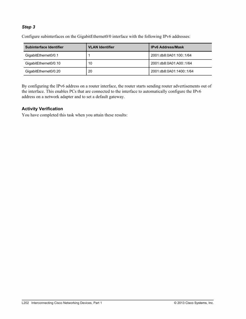
Step 3
Configure subinterfaces on the GigabitEthernet0/0 interface with the following IPv6 addresses:
Subinterface Identifier VLAN Identifier IPv6 Address/Mask
GigabitEthernet0/0.1 1 2001:db8:0A01:100::1/64
GigabitEthernet0/0.10 10 2001:db8:0A01:A00::1/64
GigabitEthernet0/0.20 20 2001:db8:0A01:1400::1/64
By configuring the IPv6 address on a router interface, the router starts sending router advertisements out ofthe interface. This enables PCs that are connected to the interface to automatically configure the IPv6address on a network adapter and to set a default gateway.
Activity VerificationYou have completed this task when you attain these results:
L202 Interconnecting Cisco Networking Devices, Part 1 © 2013 Cisco Systems, Inc.

Step 1
Verify IPv6 settings and the status on all subinterfaces:
Branch# show ipv6 interface GigabitEthernet0/0.1GigabitEthernet0/0.1 is up, line protocol is up IPv6 is enabled, link-local address is FE80::FE99:47FF:FEE5:2700 No Virtual link-local address(es): Global unicast address(es): 2001:DB8:A01:100::1, subnet is 2001:DB8:A01:100::/64 Joined group address(es): FF02::1 FF02::2 FF02::1:FF00:1 FF02::1:FFE5:2700 MTU is 1500 bytes ICMP error messages limited to one every 100 milliseconds ICMP redirects are enabled ICMP unreachables are sent ND DAD is enabled, number of DAD attempts: 1 ND reachable time is 30000 milliseconds (using 30000) ND advertised reachable time is 0 (unspecified) ND advertised retransmit interval is 0 (unspecified) ND router advertisements are sent every 200 seconds ND router advertisements live for 1800 seconds ND advertised default router preference is Medium Hosts use stateless autoconfig for addresses.Branch# show ipv6 interface GigabitEthernet0/0.10GigabitEthernet0/0.10 is up, line protocol is up IPv6 is enabled, link-local address is FE80::FE99:47FF:FEE5:2700 No Virtual link-local address(es): Global unicast address(es): 2001:DB8:A01:A00::1, subnet is 2001:DB8:A01:A00::/64 Joined group address(es): FF02::1 FF02::2 FF02::1:FF00:1 FF02::1:FFE5:2700 MTU is 1500 bytes ICMP error messages limited to one every 100 milliseconds ICMP redirects are enabled ICMP unreachables are sent ND DAD is enabled, number of DAD attempts: 1 ND reachable time is 30000 milliseconds (using 30000) ND advertised reachable time is 0 (unspecified) ND advertised retransmit interval is 0 (unspecified) ND router advertisements are sent every 200 seconds ND router advertisements live for 1800 seconds ND advertised default router preference is Medium Hosts use stateless autoconfig for addresses.Branch# show ipv6 interface GigabitEthernet0/0.20GigabitEthernet0/0.20 is up, line protocol is up IPv6 is enabled, link-local address is FE80::FE99:47FF:FEE5:2700 No Virtual link-local address(es): Global unicast address(es): 2001:DB8:A01:1400::1, subnet is 2001:DB8:A01:1400::/64 Joined group address(es): FF02::1 FF02::2 FF02::1:FF00:1 FF02::1:FFE5:2700
© 2013 Cisco Systems, Inc. Lab Guide L203
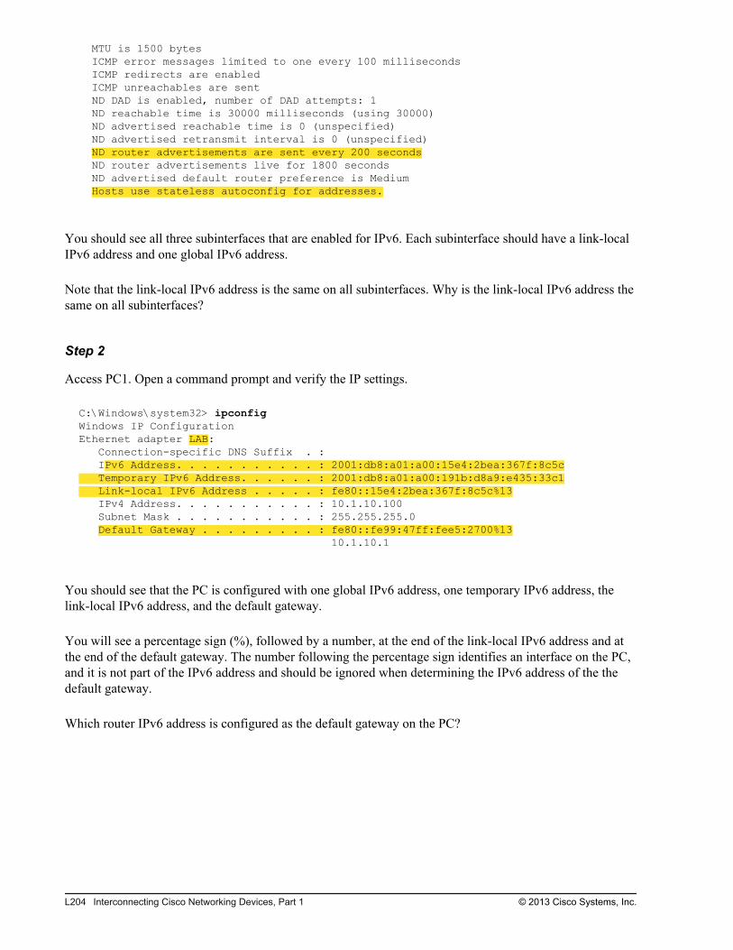
MTU is 1500 bytes ICMP error messages limited to one every 100 milliseconds ICMP redirects are enabled ICMP unreachables are sent ND DAD is enabled, number of DAD attempts: 1 ND reachable time is 30000 milliseconds (using 30000) ND advertised reachable time is 0 (unspecified) ND advertised retransmit interval is 0 (unspecified) ND router advertisements are sent every 200 seconds ND router advertisements live for 1800 seconds ND advertised default router preference is Medium Hosts use stateless autoconfig for addresses.
You should see all three subinterfaces that are enabled for IPv6. Each subinterface should have a link-localIPv6 address and one global IPv6 address.
Note that the link-local IPv6 address is the same on all subinterfaces. Why is the link-local IPv6 address thesame on all subinterfaces?
Step 2
Access PC1. Open a command prompt and verify the IP settings.
C:\Windows\system32> ipconfigWindows IP ConfigurationEthernet adapter LAB: Connection-specific DNS Suffix . : IPv6 Address. . . . . . . . . . . : 2001:db8:a01:a00:15e4:2bea:367f:8c5c Temporary IPv6 Address. . . . . . : 2001:db8:a01:a00:191b:d8a9:e435:33c1 Link-local IPv6 Address . . . . . : fe80::15e4:2bea:367f:8c5c%13 IPv4 Address. . . . . . . . . . . : 10.1.10.100 Subnet Mask . . . . . . . . . . . : 255.255.255.0 Default Gateway . . . . . . . . . : fe80::fe99:47ff:fee5:2700%13 10.1.10.1
You should see that the PC is configured with one global IPv6 address, one temporary IPv6 address, thelink-local IPv6 address, and the default gateway.
You will see a percentage sign (%), followed by a number, at the end of the link-local IPv6 address and atthe end of the default gateway. The number following the percentage sign identifies an interface on the PC,and it is not part of the IPv6 address and should be ignored when determining the IPv6 address of the thedefault gateway.
Which router IPv6 address is configured as the default gateway on the PC?
L204 Interconnecting Cisco Networking Devices, Part 1 © 2013 Cisco Systems, Inc.

Step 3
From PC1, ping the default gateway. Use the link-local IPv6 address as the destination IPv6 address.
C:\Windows\system32> ping fe80::fe99:47ff:fee5:2700Pinging fe80::fe99:47ff:fee5:2700 with 32 bytes of data:Destination host unreachable.Reply from fe80::fe99:47ff:fee5:2700: time=3msReply from fe80::fe99:47ff:fee5:2700: time<1msReply from fe80::fe99:47ff:fee5:2700: time<1msPing statistics for fe80::fe99:47ff:fee5:2700: Packets: Sent = 4, Received = 3, Lost = 1 (25% loss),Approximate round trip times in milli-seconds: Minimum = 0ms, Maximum = 3ms, Average = 1ms
The ping should be successful.
Step 4
From PC1, ping the directly connected interface of the Branch router. Use the global IPv6 address as thedestination IPv6 address.
C:\Windows\system32> ping 2001:DB8:A01:A00::1Pinging 2001:db8:a01:a00::1 with 32 bytes of data:Reply from 2001:db8:a01:a00::1: time=5msReply from 2001:db8:a01:a00::1: time<1msReply from 2001:db8:a01:a00::1: time<1msReply from 2001:db8:a01:a00::1: time<1msPing statistics for 2001:db8:a01:a00::1: Packets: Sent = 4, Received = 4, Lost = 0 (0% loss),Approximate round trip times in milli-seconds: Minimum = 0ms, Maximum = 5ms, Average = 1ms
The ping should be successful.
© 2013 Cisco Systems, Inc. Lab Guide L205
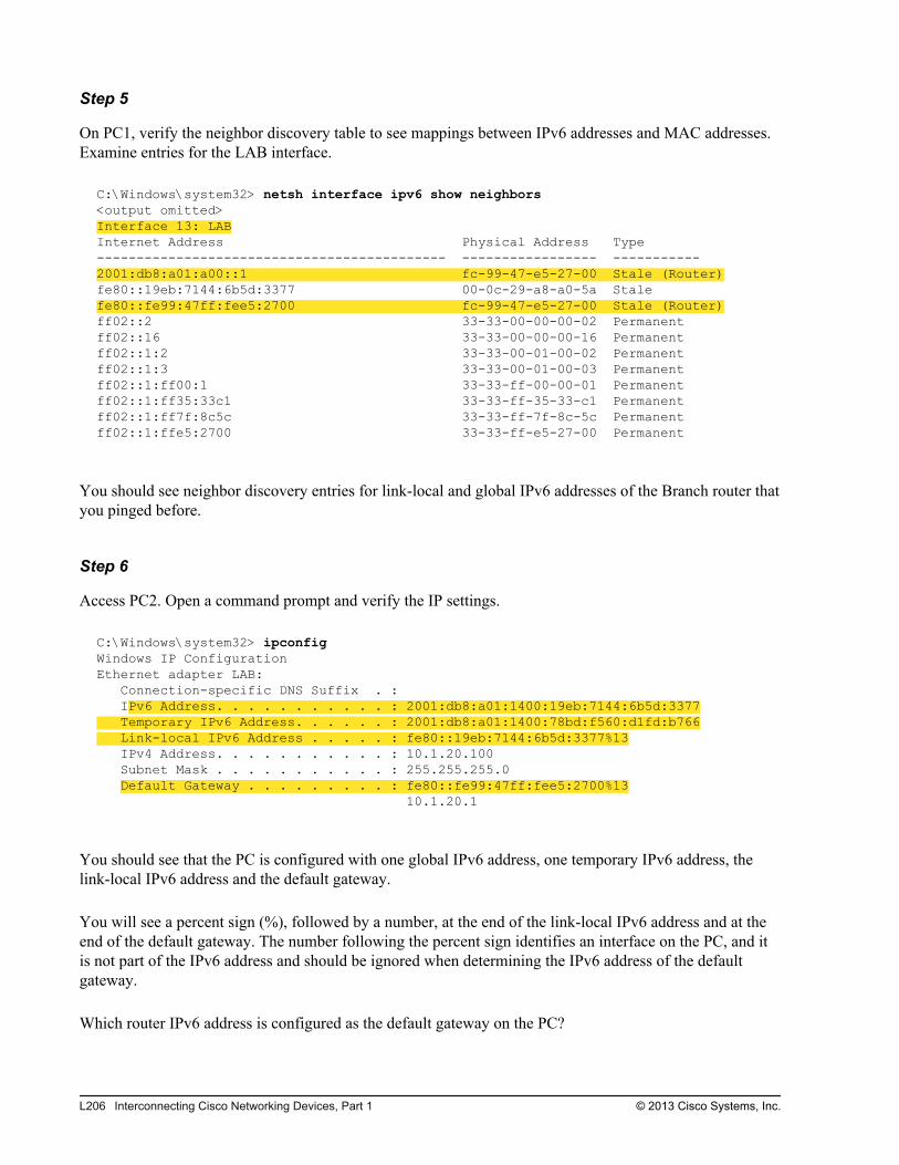
Step 5
On PC1, verify the neighbor discovery table to see mappings between IPv6 addresses and MAC addresses.Examine entries for the LAB interface.
C:\Windows\system32> netsh interface ipv6 show neighbors<output omitted>Interface 13: LABInternet Address Physical Address Type-------------------------------------------- ----------------- -----------2001:db8:a01:a00::1 fc-99-47-e5-27-00 Stale (Router)fe80::19eb:7144:6b5d:3377 00-0c-29-a8-a0-5a Stalefe80::fe99:47ff:fee5:2700 fc-99-47-e5-27-00 Stale (Router)ff02::2 33-33-00-00-00-02 Permanentff02::16 33-33-00-00-00-16 Permanentff02::1:2 33-33-00-01-00-02 Permanentff02::1:3 33-33-00-01-00-03 Permanentff02::1:ff00:1 33-33-ff-00-00-01 Permanentff02::1:ff35:33c1 33-33-ff-35-33-c1 Permanentff02::1:ff7f:8c5c 33-33-ff-7f-8c-5c Permanentff02::1:ffe5:2700 33-33-ff-e5-27-00 Permanent
You should see neighbor discovery entries for link-local and global IPv6 addresses of the Branch router thatyou pinged before.
Step 6
Access PC2. Open a command prompt and verify the IP settings.
C:\Windows\system32> ipconfigWindows IP ConfigurationEthernet adapter LAB: Connection-specific DNS Suffix . : IPv6 Address. . . . . . . . . . . : 2001:db8:a01:1400:19eb:7144:6b5d:3377 Temporary IPv6 Address. . . . . . : 2001:db8:a01:1400:78bd:f560:d1fd:b766 Link-local IPv6 Address . . . . . : fe80::19eb:7144:6b5d:3377%13 IPv4 Address. . . . . . . . . . . : 10.1.20.100 Subnet Mask . . . . . . . . . . . : 255.255.255.0 Default Gateway . . . . . . . . . : fe80::fe99:47ff:fee5:2700%13 10.1.20.1
You should see that the PC is configured with one global IPv6 address, one temporary IPv6 address, thelink-local IPv6 address and the default gateway.
You will see a percent sign (%), followed by a number, at the end of the link-local IPv6 address and at theend of the default gateway. The number following the percent sign identifies an interface on the PC, and itis not part of the IPv6 address and should be ignored when determining the IPv6 address of the defaultgateway.
Which router IPv6 address is configured as the default gateway on the PC?
L206 Interconnecting Cisco Networking Devices, Part 1 © 2013 Cisco Systems, Inc.
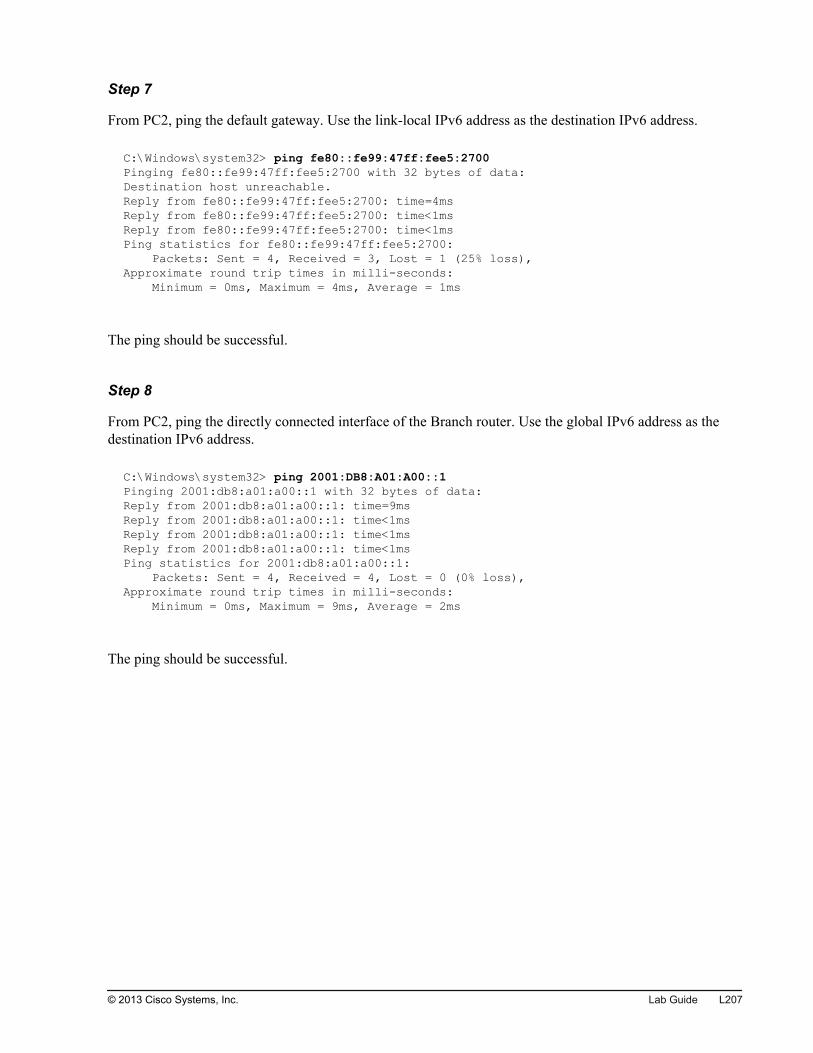
Step 7
From PC2, ping the default gateway. Use the link-local IPv6 address as the destination IPv6 address.
C:\Windows\system32> ping fe80::fe99:47ff:fee5:2700Pinging fe80::fe99:47ff:fee5:2700 with 32 bytes of data:Destination host unreachable.Reply from fe80::fe99:47ff:fee5:2700: time=4msReply from fe80::fe99:47ff:fee5:2700: time<1msReply from fe80::fe99:47ff:fee5:2700: time<1msPing statistics for fe80::fe99:47ff:fee5:2700: Packets: Sent = 4, Received = 3, Lost = 1 (25% loss),Approximate round trip times in milli-seconds: Minimum = 0ms, Maximum = 4ms, Average = 1ms
The ping should be successful.
Step 8
From PC2, ping the directly connected interface of the Branch router. Use the global IPv6 address as thedestination IPv6 address.
C:\Windows\system32> ping 2001:DB8:A01:A00::1Pinging 2001:db8:a01:a00::1 with 32 bytes of data:Reply from 2001:db8:a01:a00::1: time=9msReply from 2001:db8:a01:a00::1: time<1msReply from 2001:db8:a01:a00::1: time<1msReply from 2001:db8:a01:a00::1: time<1msPing statistics for 2001:db8:a01:a00::1: Packets: Sent = 4, Received = 4, Lost = 0 (0% loss),Approximate round trip times in milli-seconds: Minimum = 0ms, Maximum = 9ms, Average = 2ms
The ping should be successful.
© 2013 Cisco Systems, Inc. Lab Guide L207
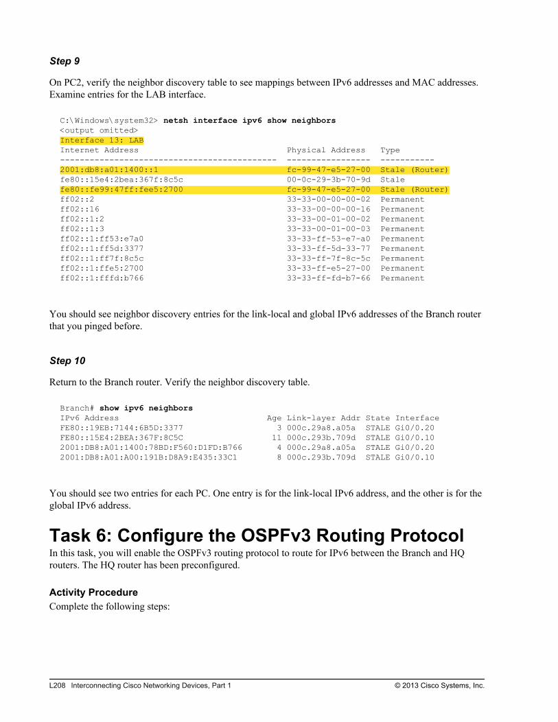
Step 9
On PC2, verify the neighbor discovery table to see mappings between IPv6 addresses and MAC addresses.Examine entries for the LAB interface.
C:\Windows\system32> netsh interface ipv6 show neighbors<output omitted>Interface 13: LABInternet Address Physical Address Type-------------------------------------------- ----------------- -----------2001:db8:a01:1400::1 fc-99-47-e5-27-00 Stale (Router)fe80::15e4:2bea:367f:8c5c 00-0c-29-3b-70-9d Stalefe80::fe99:47ff:fee5:2700 fc-99-47-e5-27-00 Stale (Router)ff02::2 33-33-00-00-00-02 Permanentff02::16 33-33-00-00-00-16 Permanentff02::1:2 33-33-00-01-00-02 Permanentff02::1:3 33-33-00-01-00-03 Permanentff02::1:ff53:e7a0 33-33-ff-53-e7-a0 Permanentff02::1:ff5d:3377 33-33-ff-5d-33-77 Permanentff02::1:ff7f:8c5c 33-33-ff-7f-8c-5c Permanentff02::1:ffe5:2700 33-33-ff-e5-27-00 Permanentff02::1:fffd:b766 33-33-ff-fd-b7-66 Permanent
You should see neighbor discovery entries for the link-local and global IPv6 addresses of the Branch routerthat you pinged before.
Step 10
Return to the Branch router. Verify the neighbor discovery table.
Branch# show ipv6 neighbors IPv6 Address Age Link-layer Addr State InterfaceFE80::19EB:7144:6B5D:3377 3 000c.29a8.a05a STALE Gi0/0.20FE80::15E4:2BEA:367F:8C5C 11 000c.293b.709d STALE Gi0/0.102001:DB8:A01:1400:78BD:F560:D1FD:B766 4 000c.29a8.a05a STALE Gi0/0.202001:DB8:A01:A00:191B:D8A9:E435:33C1 8 000c.293b.709d STALE Gi0/0.10
You should see two entries for each PC. One entry is for the link-local IPv6 address, and the other is for theglobal IPv6 address.
Task 6: Configure the OSPFv3 Routing ProtocolIn this task, you will enable the OSPFv3 routing protocol to route for IPv6 between the Branch and HQrouters. The HQ router has been preconfigured.
Activity ProcedureComplete the following steps:
L208 Interconnecting Cisco Networking Devices, Part 1 © 2013 Cisco Systems, Inc.
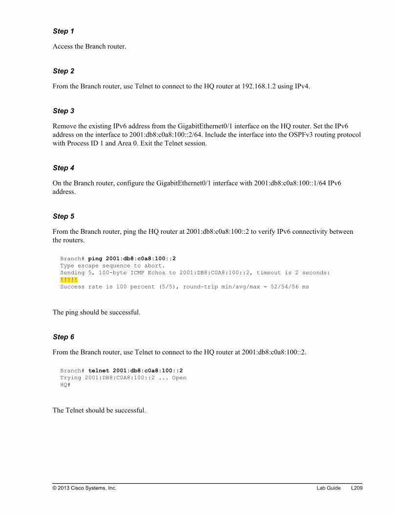
Step 1
Access the Branch router.
Step 2
From the Branch router, use Telnet to connect to the HQ router at 192.168.1.2 using IPv4.
Step 3
Remove the existing IPv6 address from the GigabitEthernet0/1 interface on the HQ router. Set the IPv6address on the interface to 2001:db8:c0a8:100::2/64. Include the interface into the OSPFv3 routing protocolwith Process ID 1 and Area 0. Exit the Telnet session.
Step 4
On the Branch router, configure the GigabitEthernet0/1 interface with 2001:db8:c0a8:100::1/64 IPv6address.
Step 5
From the Branch router, ping the HQ router at 2001:db8:c0a8:100::2 to verify IPv6 connectivity betweenthe routers.
Branch# ping 2001:db8:c0a8:100::2Type escape sequence to abort.Sending 5, 100-byte ICMP Echos to 2001:DB8:C0A8:100::2, timeout is 2 seconds:!!!!!Success rate is 100 percent (5/5), round-trip min/avg/max = 52/54/56 ms
The ping should be successful.
Step 6
From the Branch router, use Telnet to connect to the HQ router at 2001:db8:c0a8:100::2.
Branch# telnet 2001:db8:c0a8:100::2Trying 2001:DB8:C0A8:100::2 ... OpenHQ#
The Telnet should be successful.
© 2013 Cisco Systems, Inc. Lab Guide L209
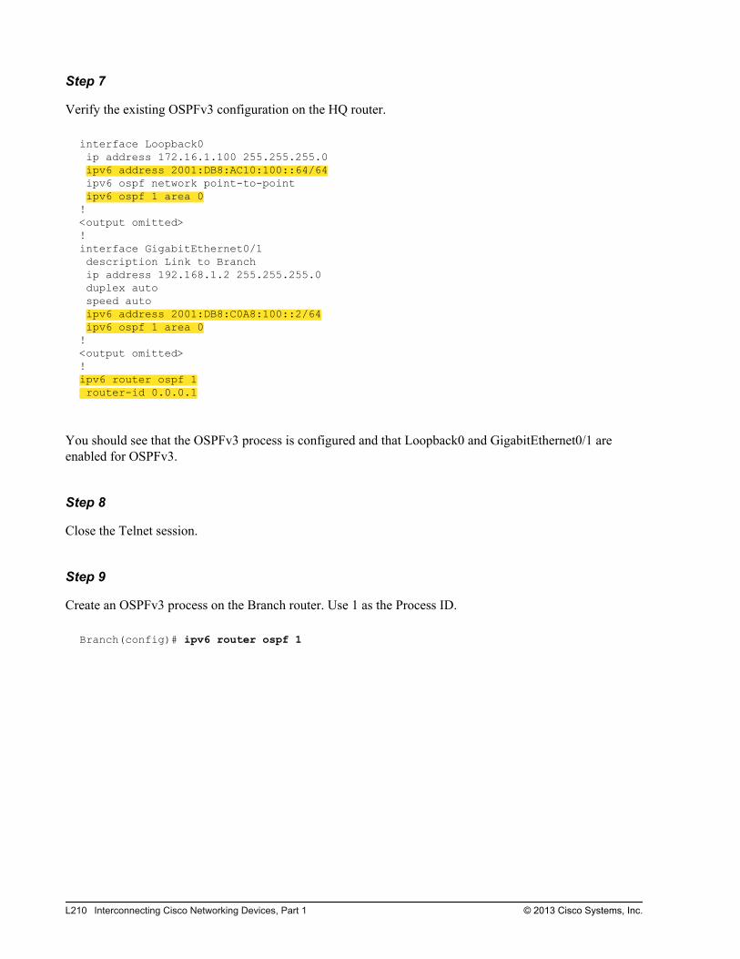
Step 7
Verify the existing OSPFv3 configuration on the HQ router.
interface Loopback0 ip address 172.16.1.100 255.255.255.0 ipv6 address 2001:DB8:AC10:100::64/64 ipv6 ospf network point-to-point ipv6 ospf 1 area 0!<output omitted>!interface GigabitEthernet0/1 description Link to Branch ip address 192.168.1.2 255.255.255.0 duplex auto speed auto ipv6 address 2001:DB8:C0A8:100::2/64 ipv6 ospf 1 area 0!<output omitted>!ipv6 router ospf 1 router-id 0.0.0.1
You should see that the OSPFv3 process is configured and that Loopback0 and GigabitEthernet0/1 areenabled for OSPFv3.
Step 8
Close the Telnet session.
Step 9
Create an OSPFv3 process on the Branch router. Use 1 as the Process ID.
Branch(config)# ipv6 router ospf 1
L210 Interconnecting Cisco Networking Devices, Part 1 © 2013 Cisco Systems, Inc.
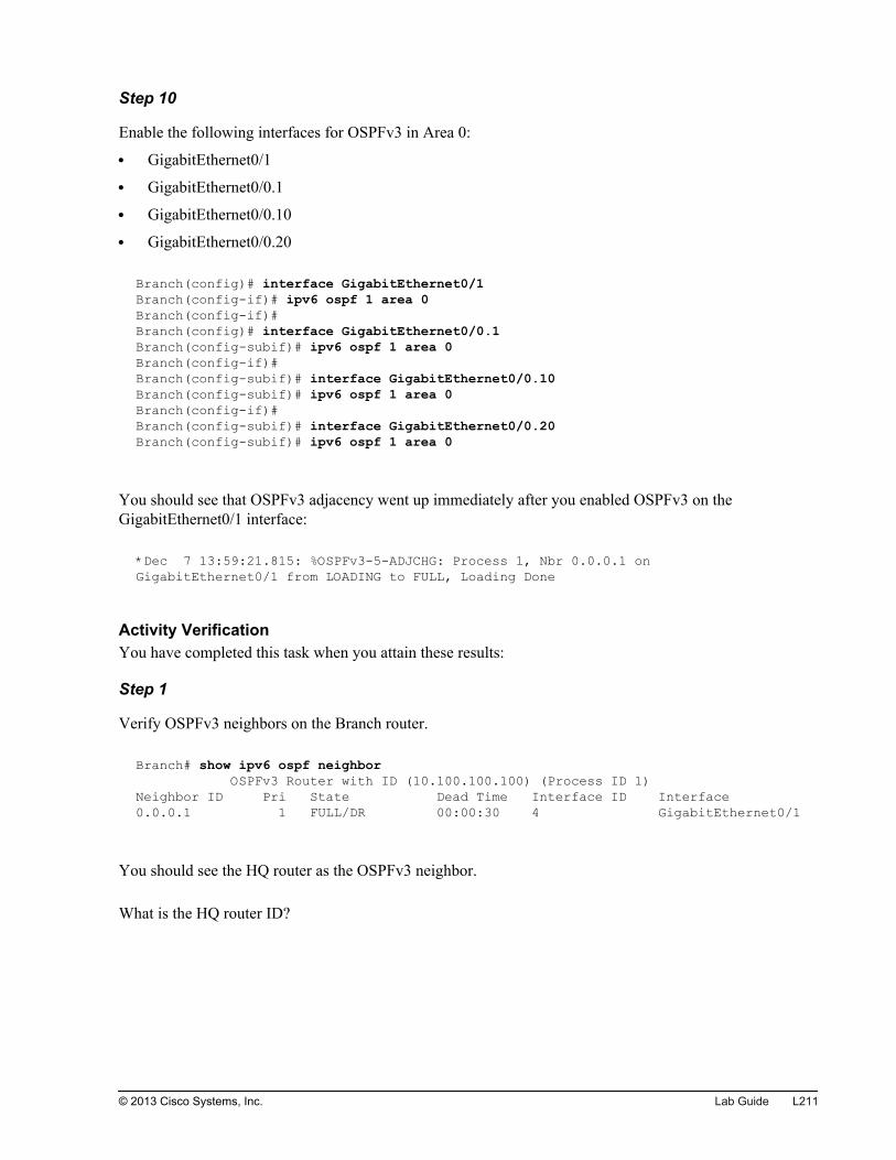
Step 10
Enable the following interfaces for OSPFv3 in Area 0:
GigabitEthernet0/1
GigabitEthernet0/0.1
GigabitEthernet0/0.10
GigabitEthernet0/0.20
Branch(config)# interface GigabitEthernet0/1Branch(config-if)# ipv6 ospf 1 area 0Branch(config-if)# Branch(config)# interface GigabitEthernet0/0.1Branch(config-subif)# ipv6 ospf 1 area 0 Branch(config-if)# Branch(config-subif)# interface GigabitEthernet0/0.10Branch(config-subif)# ipv6 ospf 1 area 0 Branch(config-if)# Branch(config-subif)# interface GigabitEthernet0/0.20Branch(config-subif)# ipv6 ospf 1 area 0
You should see that OSPFv3 adjacency went up immediately after you enabled OSPFv3 on theGigabitEthernet0/1 interface:
*Dec 7 13:59:21.815: %OSPFv3-5-ADJCHG: Process 1, Nbr 0.0.0.1 on GigabitEthernet0/1 from LOADING to FULL, Loading Done
Activity VerificationYou have completed this task when you attain these results:
Step 1
Verify OSPFv3 neighbors on the Branch router.
Branch# show ipv6 ospf neighbor OSPFv3 Router with ID (10.100.100.100) (Process ID 1)Neighbor ID Pri State Dead Time Interface ID Interface0.0.0.1 1 FULL/DR 00:00:30 4 GigabitEthernet0/1
You should see the HQ router as the OSPFv3 neighbor.
What is the HQ router ID?
© 2013 Cisco Systems, Inc. Lab Guide L211

Step 2
Verify OSPFv3 settings on the Branch router.
Branch# show ipv6 ospf Routing Process "ospfv3 1" with ID 10.100.100.100 Event-log enabled, Maximum number of events: 1000, Mode: cyclic Initial SPF schedule delay 5000 msecs Minimum hold time between two consecutive SPFs 10000 msecs Maximum wait time between two consecutive SPFs 10000 msecs Minimum LSA interval 5 secs Minimum LSA arrival 1000 msecs LSA group pacing timer 240 secs Interface flood pacing timer 33 msecs Retransmission pacing timer 66 msecs Number of external LSA 0. Checksum Sum 0x000000 Number of areas in this router is 1. 1 normal 0 stub 0 nssa Graceful restart helper support enabled Reference bandwidth unit is 100 mbps Area BACKBONE(0) Number of interfaces in this area is 4 SPF algorithm executed 3 times Number of LSA 9. Checksum Sum 0x0523AD Number of DCbitless LSA 0 Number of indication LSA 0 Number of DoNotAge LSA 0 Flood list length 0
You should see that OSPFv3 is enabled for four interfaces in Area 0.
What is the Branch router ID?
L212 Interconnecting Cisco Networking Devices, Part 1 © 2013 Cisco Systems, Inc.
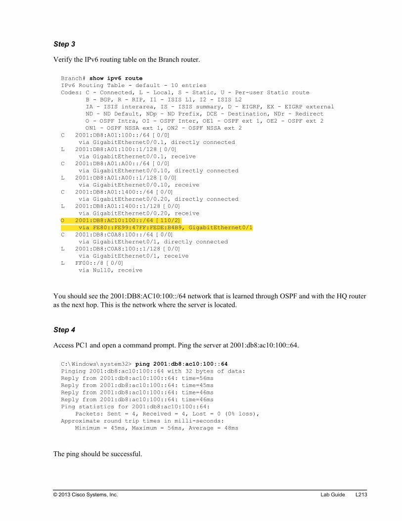
Step 3
Verify the IPv6 routing table on the Branch router.
Branch# show ipv6 routeIPv6 Routing Table - default - 10 entriesCodes: C - Connected, L - Local, S - Static, U - Per-user Static route B - BGP, R - RIP, I1 - ISIS L1, I2 - ISIS L2 IA - ISIS interarea, IS - ISIS summary, D - EIGRP, EX - EIGRP external ND - ND Default, NDp - ND Prefix, DCE - Destination, NDr - Redirect O - OSPF Intra, OI - OSPF Inter, OE1 - OSPF ext 1, OE2 - OSPF ext 2 ON1 - OSPF NSSA ext 1, ON2 - OSPF NSSA ext 2C 2001:DB8:A01:100::/64 [0/0] via GigabitEthernet0/0.1, directly connectedL 2001:DB8:A01:100::1/128 [0/0] via GigabitEthernet0/0.1, receiveC 2001:DB8:A01:A00::/64 [0/0] via GigabitEthernet0/0.10, directly connectedL 2001:DB8:A01:A00::1/128 [0/0] via GigabitEthernet0/0.10, receiveC 2001:DB8:A01:1400::/64 [0/0] via GigabitEthernet0/0.20, directly connectedL 2001:DB8:A01:1400::1/128 [0/0] via GigabitEthernet0/0.20, receiveO 2001:DB8:AC10:100::/64 [110/2] via FE80::FE99:47FF:FEDE:B4B9, GigabitEthernet0/1C 2001:DB8:C0A8:100::/64 [0/0] via GigabitEthernet0/1, directly connectedL 2001:DB8:C0A8:100::1/128 [0/0] via GigabitEthernet0/1, receiveL FF00::/8 [0/0] via Null0, receive
You should see the 2001:DB8:AC10:100::/64 network that is learned through OSPF and with the HQ routeras the next hop. This is the network where the server is located.
Step 4
Access PC1 and open a command prompt. Ping the server at 2001:db8:ac10:100::64.
C:\Windows\system32> ping 2001:db8:ac10:100::64Pinging 2001:db8:ac10:100::64 with 32 bytes of data:Reply from 2001:db8:ac10:100::64: time=56msReply from 2001:db8:ac10:100::64: time=45msReply from 2001:db8:ac10:100::64: time=46msReply from 2001:db8:ac10:100::64: time=46msPing statistics for 2001:db8:ac10:100::64: Packets: Sent = 4, Received = 4, Lost = 0 (0% loss),Approximate round trip times in milli-seconds: Minimum = 45ms, Maximum = 56ms, Average = 48ms
The ping should be successful.
© 2013 Cisco Systems, Inc. Lab Guide L213
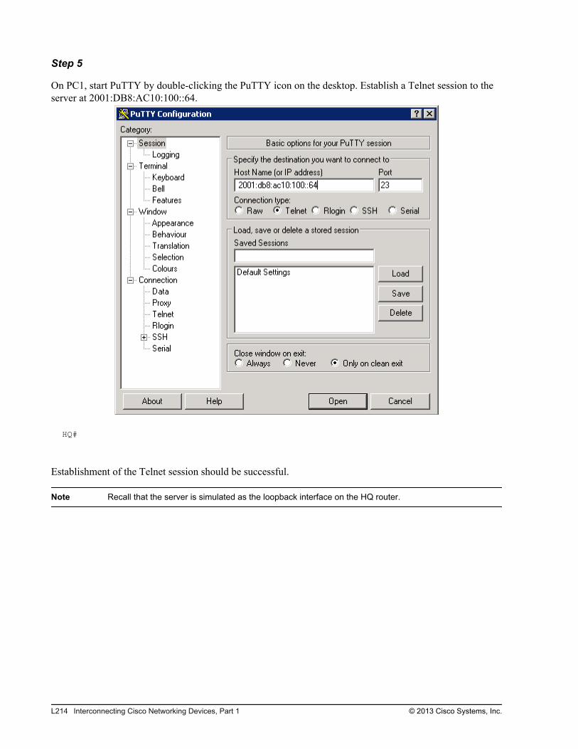
Step 5
On PC1, start PuTTY by double-clicking the PuTTY icon on the desktop. Establish a Telnet session to theserver at 2001:DB8:AC10:100::64.
HQ#
Establishment of the Telnet session should be successful.
Note Recall that the server is simulated as the loopback interface on the HQ router.
L214 Interconnecting Cisco Networking Devices, Part 1 © 2013 Cisco Systems, Inc.
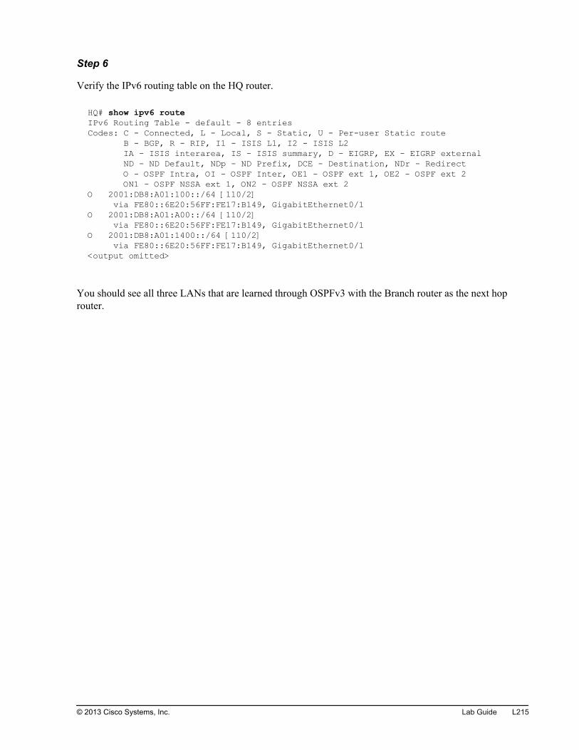
Step 6
Verify the IPv6 routing table on the HQ router.
HQ# show ipv6 routeIPv6 Routing Table - default - 8 entriesCodes: C - Connected, L - Local, S - Static, U - Per-user Static route B - BGP, R - RIP, I1 - ISIS L1, I2 - ISIS L2 IA - ISIS interarea, IS - ISIS summary, D - EIGRP, EX - EIGRP external ND - ND Default, NDp - ND Prefix, DCE - Destination, NDr - Redirect O - OSPF Intra, OI - OSPF Inter, OE1 - OSPF ext 1, OE2 - OSPF ext 2 ON1 - OSPF NSSA ext 1, ON2 - OSPF NSSA ext 2O 2001:DB8:A01:100::/64 [110/2] via FE80::6E20:56FF:FE17:B149, GigabitEthernet0/1O 2001:DB8:A01:A00::/64 [110/2] via FE80::6E20:56FF:FE17:B149, GigabitEthernet0/1O 2001:DB8:A01:1400::/64 [110/2] via FE80::6E20:56FF:FE17:B149, GigabitEthernet0/1<output omitted>
You should see all three LANs that are learned through OSPFv3 with the Branch router as the next hoprouter.
© 2013 Cisco Systems, Inc. Lab Guide L215

L216 Interconnecting Cisco Networking Devices, Part 1 © 2013 Cisco Systems, Inc.
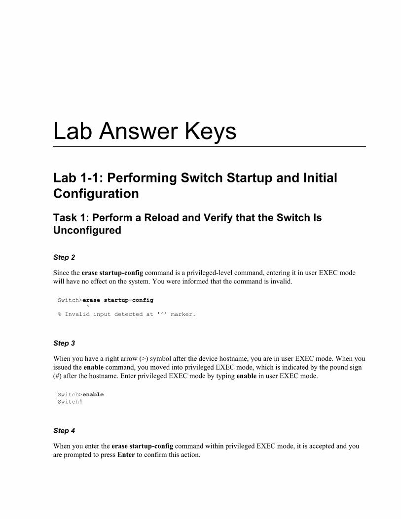
Lab Answer Keys
Lab 1-1: Performing Switch Startup and InitialConfiguration
Task 1: Perform a Reload and Verify that the Switch IsUnconfigured
Step 2
Since the erase startup-config command is a privileged-level command, entering it in user EXEC modewill have no effect on the system. You were informed that the command is invalid.
Switch>erase startup-config ^% Invalid input detected at '^' marker.
Step 3
When you have a right arrow (>) symbol after the device hostname, you are in user EXEC mode. When youissued the enable command, you moved into privileged EXEC mode, which is indicated by the pound sign(#) after the hostname. Enter privileged EXEC mode by typing enable in user EXEC mode.
Switch>enableSwitch#
Step 4
When you enter the erase startup-config command within privileged EXEC mode, it is accepted and youare prompted to press Enter to confirm this action.
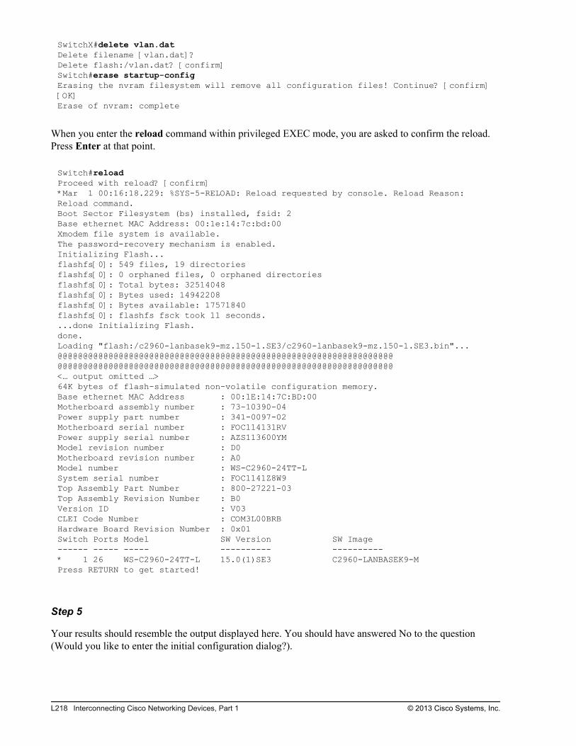
SwitchX#delete vlan.datDelete filename [vlan.dat]? Delete flash:/vlan.dat? [confirm]Switch#erase startup-configErasing the nvram filesystem will remove all configuration files! Continue? [confirm][OK]Erase of nvram: complete
When you enter the reload command within privileged EXEC mode, you are asked to confirm the reload.Press Enter at that point.
Switch#reloadProceed with reload? [confirm]*Mar 1 00:16:18.229: %SYS-5-RELOAD: Reload requested by console. Reload Reason: Reload command.Boot Sector Filesystem (bs) installed, fsid: 2Base ethernet MAC Address: 00:1e:14:7c:bd:00Xmodem file system is available.The password-recovery mechanism is enabled.Initializing Flash...flashfs[0]: 549 files, 19 directoriesflashfs[0]: 0 orphaned files, 0 orphaned directoriesflashfs[0]: Total bytes: 32514048flashfs[0]: Bytes used: 14942208flashfs[0]: Bytes available: 17571840flashfs[0]: flashfs fsck took 11 seconds....done Initializing Flash.done.Loading "flash:/c2960-lanbasek9-mz.150-1.SE3/c2960-lanbasek9-mz.150-1.SE3.bin"... @@@@@@@@@@@@@@@@@@@@@@@@@@@@@@@@@@@@@@@@@@@@@@@@@@@@@@@@@@@@@@@@@@@@@@@@@@@@@@@@@@@@@@@@@@@@@@@@@@@@@@@@@@@@@@@@@@@@@@@@@@@@@@@@@@@@<… output omitted …>64K bytes of flash-simulated non-volatile configuration memory.Base ethernet MAC Address : 00:1E:14:7C:BD:00Motherboard assembly number : 73-10390-04Power supply part number : 341-0097-02Motherboard serial number : FOC114131RVPower supply serial number : AZS113600YMModel revision number : D0Motherboard revision number : A0Model number : WS-C2960-24TT-LSystem serial number : FOC1141Z8W9Top Assembly Part Number : 800-27221-03Top Assembly Revision Number : B0Version ID : V03CLEI Code Number : COM3L00BRBHardware Board Revision Number : 0x01Switch Ports Model SW Version SW Image------ ----- ----- ---------- ----------* 1 26 WS-C2960-24TT-L 15.0(1)SE3 C2960-LANBASEK9-MPress RETURN to get started!
Step 5
Your results should resemble the output displayed here. You should have answered No to the question(Would you like to enter the initial configuration dialog?).
L218 Interconnecting Cisco Networking Devices, Part 1 © 2013 Cisco Systems, Inc.
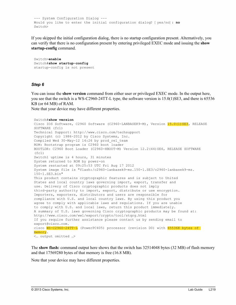
--- System Configuration Dialog ---Would you like to enter the initial configuration dialog? [yes/no]: noSwitch>
If you skipped the initial configuration dialog, there is no startup configuration present. Alternatively, youcan verify that there is no configuration present by entering privileged EXEC mode and issuing the showstartup-config command.
Switch>enableSwitch#show startup-configstartup-config is not present
Step 6
You can issue the show version command from either user or privileged EXEC mode. In the output here,you see that the switch is a WS-C2960-24TT-L type, the software version is 15.0(1)SE3, and there is 65536KB (or 64 MB) of RAM.Note that your device may have different properties.
Switch#show versionCisco IOS Software, C2960 Software (C2960-LANBASEK9-M), Version 15.0(1)SE3, RELEASE SOFTWARE (fc1)Technical Support: http://www.cisco.com/techsupportCopyright (c) 1986-2012 by Cisco Systems, Inc.Compiled Wed 30-May-12 14:26 by prod_rel_teamROM: Bootstrap program is C2960 boot loaderBOOTLDR: C2960 Boot Loader (C2960-HBOOT-M) Version 12.2(44)SE6, RELEASE SOFTWARE (fc1)Switch1 uptime is 4 hours, 31 minutesSystem returned to ROM by power-onSystem restarted at 09:25:53 UTC Fri Aug 17 2012System image file is "flash:/c2960-lanbasek9-mz.150-1.SE3/c2960-lanbasek9-mz.150-1.SE3.bin"This product contains cryptographic features and is subject to UnitedStates and local country laws governing import, export, transfer anduse. Delivery of Cisco cryptographic products does not implythird-party authority to import, export, distribute or use encryption.Importers, exporters, distributors and users are responsible forcompliance with U.S. and local country laws. By using this product youagree to comply with applicable laws and regulations. If you are unableto comply with U.S. and local laws, return this product immediately.A summary of U.S. laws governing Cisco cryptographic products may be found at:http://www.cisco.com/wwl/export/crypto/tool/stqrg.htmlIf you require further assistance please contact us by sending email [email protected] WS-C2960-24TT-L (PowerPC405) processor (revision D0) with 65536K bytes of memory.<… output omitted …>
The show flash: command output here shows that the switch has 32514048 bytes (32 MB) of flash memoryand that 17569280 bytes of that memory is free (16.8 MB).
Note that your device may have different properties.
© 2013 Cisco Systems, Inc. Lab Guide L219
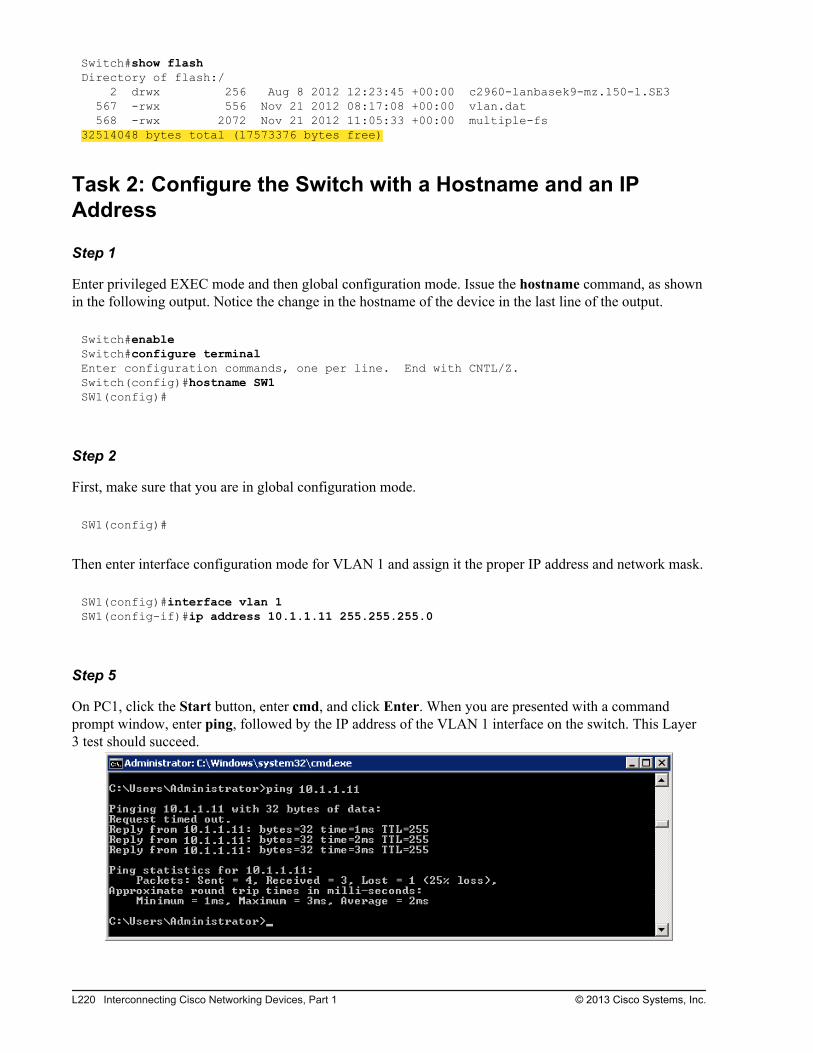
Switch#show flashDirectory of flash:/ 2 drwx 256 Aug 8 2012 12:23:45 +00:00 c2960-lanbasek9-mz.150-1.SE3 567 -rwx 556 Nov 21 2012 08:17:08 +00:00 vlan.dat 568 -rwx 2072 Nov 21 2012 11:05:33 +00:00 multiple-fs32514048 bytes total (17573376 bytes free)
Task 2: Configure the Switch with a Hostname and an IPAddress
Step 1
Enter privileged EXEC mode and then global configuration mode. Issue the hostname command, as shownin the following output. Notice the change in the hostname of the device in the last line of the output.
Switch#enableSwitch#configure terminalEnter configuration commands, one per line. End with CNTL/Z.Switch(config)#hostname SW1SW1(config)#
Step 2
First, make sure that you are in global configuration mode.
SW1(config)#
Then enter interface configuration mode for VLAN 1 and assign it the proper IP address and network mask.
SW1(config)#interface vlan 1SW1(config-if)#ip address 10.1.1.11 255.255.255.0
Step 5
On PC1, click the Start button, enter cmd, and click Enter. When you are presented with a commandprompt window, enter ping, followed by the IP address of the VLAN 1 interface on the switch. This Layer3 test should succeed.
L220 Interconnecting Cisco Networking Devices, Part 1 © 2013 Cisco Systems, Inc.

Task 3: Explore Context-Sensitive Help
Step 1
After you enter privileged EXEC mode and enter ?, you are presented with a list of available commands.Each command is listed with a description.
SW1>enableSW1#?Exec commands: access-enable Create a temporary Access-List entry access-profile Apply user-profile to interface access-template Create a temporary Access-List entry archive manage archive files beep Blocks Extensible Exchange Protocol commands<… output omitted …> where List active connections write Write running configuration to memory, network, or terminal
Step 2
First, make sure that you are in privileged EXEC mode. Enter clock, followed by ?. Complete theconfiguration as displayed here.
SW1#clock ? set Set the time and dateSW1#clock set ? hh:mm:ss Current TimeSW1#clock set 12:57:22 ? <1-31> Day of the month MONTH Month of the yearSW1#clock set 12:57:22 17 ? MONTH Month of the yearSW1#clock set 12:57:22 17 8 ?% Unrecognized commandLan_Switch_1#clock set 12:57:22 17 August ? <1993-2035> YearSW1#clock set 12:57:22 17 August 2012 ? <cr>SW1#clock set 12:57:22 17 August 2012
Step 3
When you are familiar only with how a command begins, you can get help by using the ? command. It willlist all commands that begin with the sequence of letters that you entered.
© 2013 Cisco Systems, Inc. Lab Guide L221
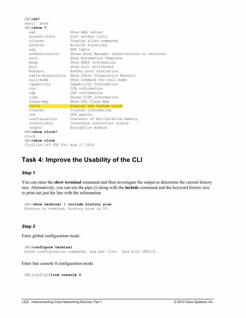
SW1#sh?shell showSW1#show ? aaa Show AAA values access-lists List access lists aliases Display alias commands archive Archive functions arp ARP table authentication Shows Auth Manager registrations or sessions auto Show Automation Template beep Show BEEP information boot show boot attributes buffers Buffer pool statistics cable-diagnostics Show Cable Diagnostics Results call-home Show command for call home capability Capability Information cca CCA information cdp CDP information cisp Shows CISP information class-map Show CPL Class Map clock Display the system clock cluster Cluster information cns CNS agents configuration Contents of Non-Volatile memory controllers Interface controller status crypto Encryption moduleSW1#show clock?clockSW1#show clock13:01:24.145 UTC Fri Aug 17 2012
Task 4: Improve the Usability of the CLI
Step 1
You can enter the show terminal command and then investigate the output to determine the current historysize. Alternatively, you can use the pipe (|) along with the include command and the keyword history sizeto print out just the line with the information.
SW1>show terminal | include history sizeHistory is enabled, history size is 20.
Step 2
Enter global configuration mode.
SW1#configure terminalEnter configuration commands, one per line. End with CNTL/Z.
Enter line console 0 configuration mode.
SW1(config)#line console 0
L222 Interconnecting Cisco Networking Devices, Part 1 © 2013 Cisco Systems, Inc.

Change the history size to 100.
SW1(config-line)#history size 100
Issue the exit command twice to get back to privileged EXEC mode.
SW1(config-line)#exitSW1(config)#exit
Verify that the history size is changed.
SW1#show terminal | i history sizeHistory is enabled, history size is 100.
Step 3
You must be in global configuration mode before issuing the no ip domain lookup command.
SW1>enableSW1#configure terminalSW1(config)#no ip domain-lookup
Step 4
Issue the exec-timeout 60 command to set the console timeout expiration timer to one hour.
SW1(config-line)#exec-timeout 60
Verify that idle exec timeout is set to one hour. Use the verification command directly from consoleconfiguration mode.
SW1(config-line)#do show terminal | begin TimeoutsTimeouts: Idle EXEC Idle Session Modem Answer Session Dispatch 01:00:00 never none not set<output omitted>SW1(config-line)#exit
Step 5
Make sure that you are in global configuration mode and then enter line console 0 configuration mode. Last,enable synchronous logging as shown in the output here.
SW1(config)#line console 0SW1(config-line)#logging synchronousSW1(config-line)#exitSW1(config)#exit
© 2013 Cisco Systems, Inc. Lab Guide L223
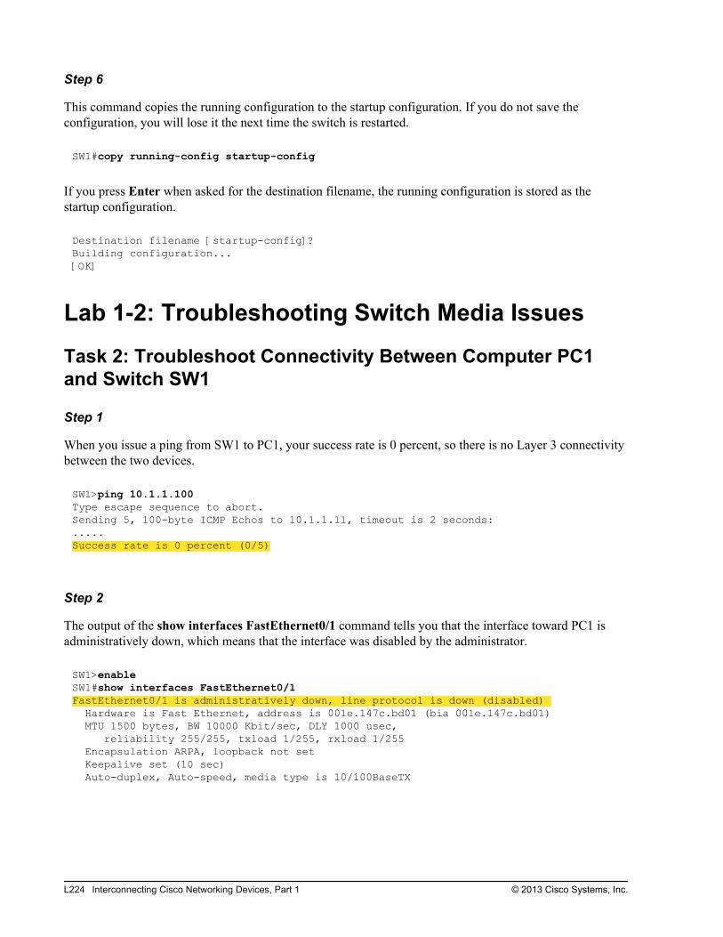
Step 6
This command copies the running configuration to the startup configuration. If you do not save theconfiguration, you will lose it the next time the switch is restarted.
SW1#copy running-config startup-config
If you press Enter when asked for the destination filename, the running configuration is stored as thestartup configuration.
Destination filename [startup-config]?Building configuration...[OK]
Lab 1-2: Troubleshooting Switch Media Issues
Task 2: Troubleshoot Connectivity Between Computer PC1and Switch SW1
Step 1
When you issue a ping from SW1 to PC1, your success rate is 0 percent, so there is no Layer 3 connectivitybetween the two devices.
SW1>ping 10.1.1.100Type escape sequence to abort.Sending 5, 100-byte ICMP Echos to 10.1.1.11, timeout is 2 seconds:.....Success rate is 0 percent (0/5)
Step 2
The output of the show interfaces FastEthernet0/1 command tells you that the interface toward PC1 isadministratively down, which means that the interface was disabled by the administrator.
SW1>enableSW1#show interfaces FastEthernet0/1FastEthernet0/1 is administratively down, line protocol is down (disabled) Hardware is Fast Ethernet, address is 001e.147c.bd01 (bia 001e.147c.bd01) MTU 1500 bytes, BW 10000 Kbit/sec, DLY 1000 usec, reliability 255/255, txload 1/255, rxload 1/255 Encapsulation ARPA, loopback not set Keepalive set (10 sec) Auto-duplex, Auto-speed, media type is 10/100BaseTX
L224 Interconnecting Cisco Networking Devices, Part 1 © 2013 Cisco Systems, Inc.
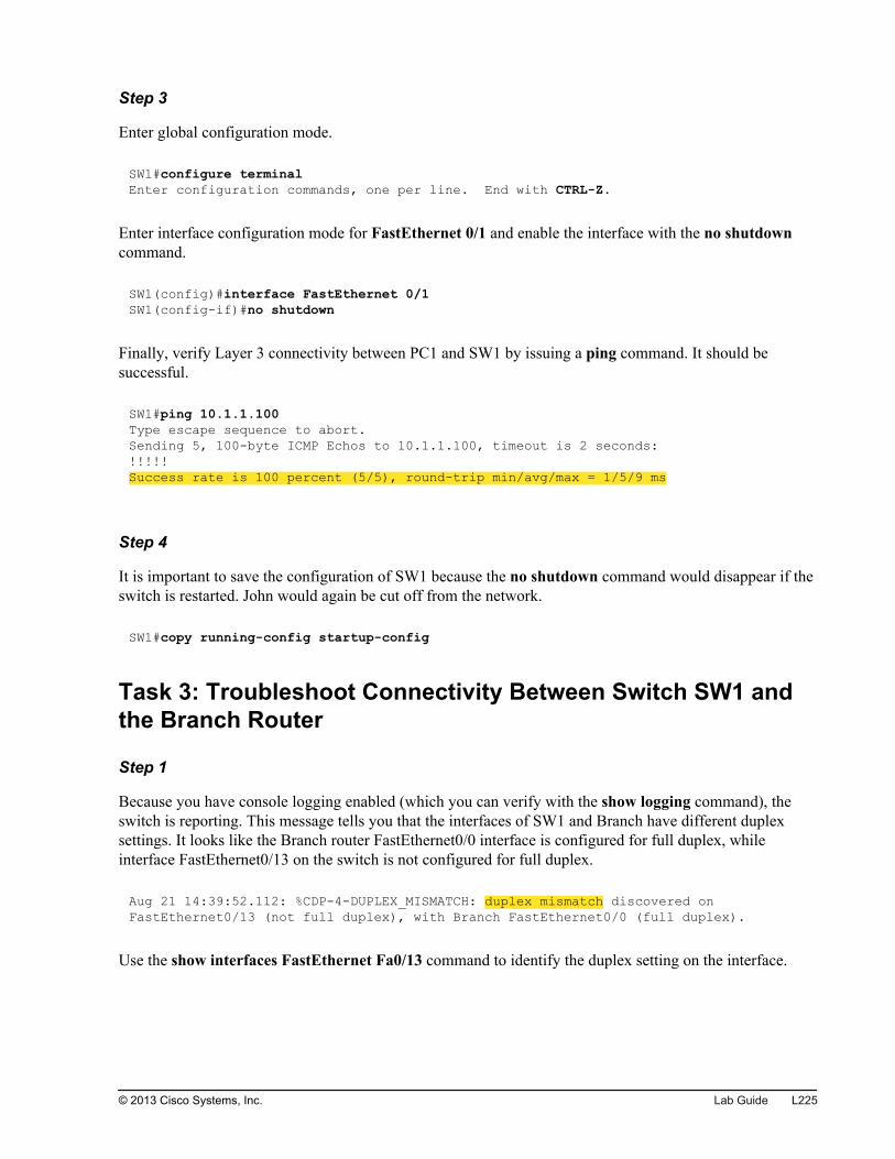
Step 3
Enter global configuration mode.
SW1#configure terminalEnter configuration commands, one per line. End with CTRL-Z.
Enter interface configuration mode for FastEthernet 0/1 and enable the interface with the no shutdowncommand.
SW1(config)#interface FastEthernet 0/1SW1(config-if)#no shutdown
Finally, verify Layer 3 connectivity between PC1 and SW1 by issuing a ping command. It should besuccessful.
SW1#ping 10.1.1.100Type escape sequence to abort.Sending 5, 100-byte ICMP Echos to 10.1.1.100, timeout is 2 seconds:!!!!!Success rate is 100 percent (5/5), round-trip min/avg/max = 1/5/9 ms
Step 4
It is important to save the configuration of SW1 because the no shutdown command would disappear if theswitch is restarted. John would again be cut off from the network.
SW1#copy running-config startup-config
Task 3: Troubleshoot Connectivity Between Switch SW1 andthe Branch Router
Step 1
Because you have console logging enabled (which you can verify with the show logging command), theswitch is reporting. This message tells you that the interfaces of SW1 and Branch have different duplexsettings. It looks like the Branch router FastEthernet0/0 interface is configured for full duplex, whileinterface FastEthernet0/13 on the switch is not configured for full duplex.
Aug 21 14:39:52.112: %CDP-4-DUPLEX_MISMATCH: duplex mismatch discovered on FastEthernet0/13 (not full duplex), with Branch FastEthernet0/0 (full duplex).
Use the show interfaces FastEthernet Fa0/13 command to identify the duplex setting on the interface.
© 2013 Cisco Systems, Inc. Lab Guide L225
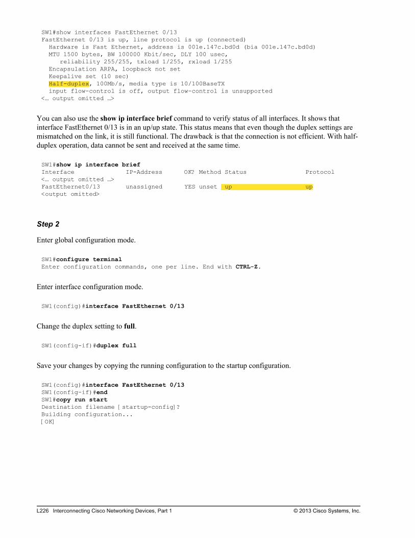
SW1#show interfaces FastEthernet 0/13FastEthernet 0/13 is up, line protocol is up (connected) Hardware is Fast Ethernet, address is 001e.147c.bd0d (bia 001e.147c.bd0d) MTU 1500 bytes, BW 100000 Kbit/sec, DLY 100 usec, reliability 255/255, txload 1/255, rxload 1/255 Encapsulation ARPA, loopback not set Keepalive set (10 sec) Half-duplex, 100Mb/s, media type is 10/100BaseTX input flow-control is off, output flow-control is unsupported<… output omitted …>
You can also use the show ip interface brief command to verify status of all interfaces. It shows thatinterface FastEthernet 0/13 is in an up/up state. This status means that even though the duplex settings aremismatched on the link, it is still functional. The drawback is that the connection is not efficient. With half-duplex operation, data cannot be sent and received at the same time.
SW1#show ip interface briefInterface IP-Address OK? Method Status Protocol<… output omitted …>FastEthernet0/13 unassigned YES unset up up<output omitted>
Step 2
Enter global configuration mode.
SW1#configure terminalEnter configuration commands, one per line. End with CTRL-Z.
Enter interface configuration mode.
SW1(config)#interface FastEthernet 0/13
Change the duplex setting to full.
SW1(config-if)#duplex full
Save your changes by copying the running configuration to the startup configuration.
SW1(config)#interface FastEthernet 0/13SW1(config-if)#endSW1#copy run startDestination filename [startup-config]?Building configuration...[OK]
L226 Interconnecting Cisco Networking Devices, Part 1 © 2013 Cisco Systems, Inc.
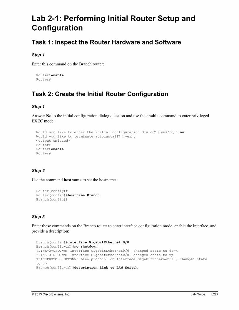
Lab 2-1: Performing Initial Router Setup andConfiguration
Task 1: Inspect the Router Hardware and Software
Step 1
Enter this command on the Branch router:
Router>enableRouter#
Task 2: Create the Initial Router Configuration
Step 1
Answer No to the initial configuration dialog question and use the enable command to enter privilegedEXEC mode.
Would you like to enter the initial configuration dialog? [yes/no]: noWould you like to terminate autoinstall? [yes]: <output omitted>Router>Router>enableRouter#
Step 2
Use the command hostname to set the hostname.
Router(config)#Router(config)#hostname BranchBranch(config)#
Step 3
Enter these commands on the Branch router to enter interface configuration mode, enable the interface, andprovide a description:
Branch(config)#interface GigabitEthernet 0/0Branch(config-if)#no shutdown%LINK-3-UPDOWN: Interface GigabitEthernet0/0, changed state to down%LINK-3-UPDOWN: Interface GigabitEthernet0/0, changed state to up%LINEPROTO-5-UPDOWN: Line protocol on Interface GigabitEthernet0/0, changed state to upBranch(config-if)#description Link to LAN Switch
© 2013 Cisco Systems, Inc. Lab Guide L227
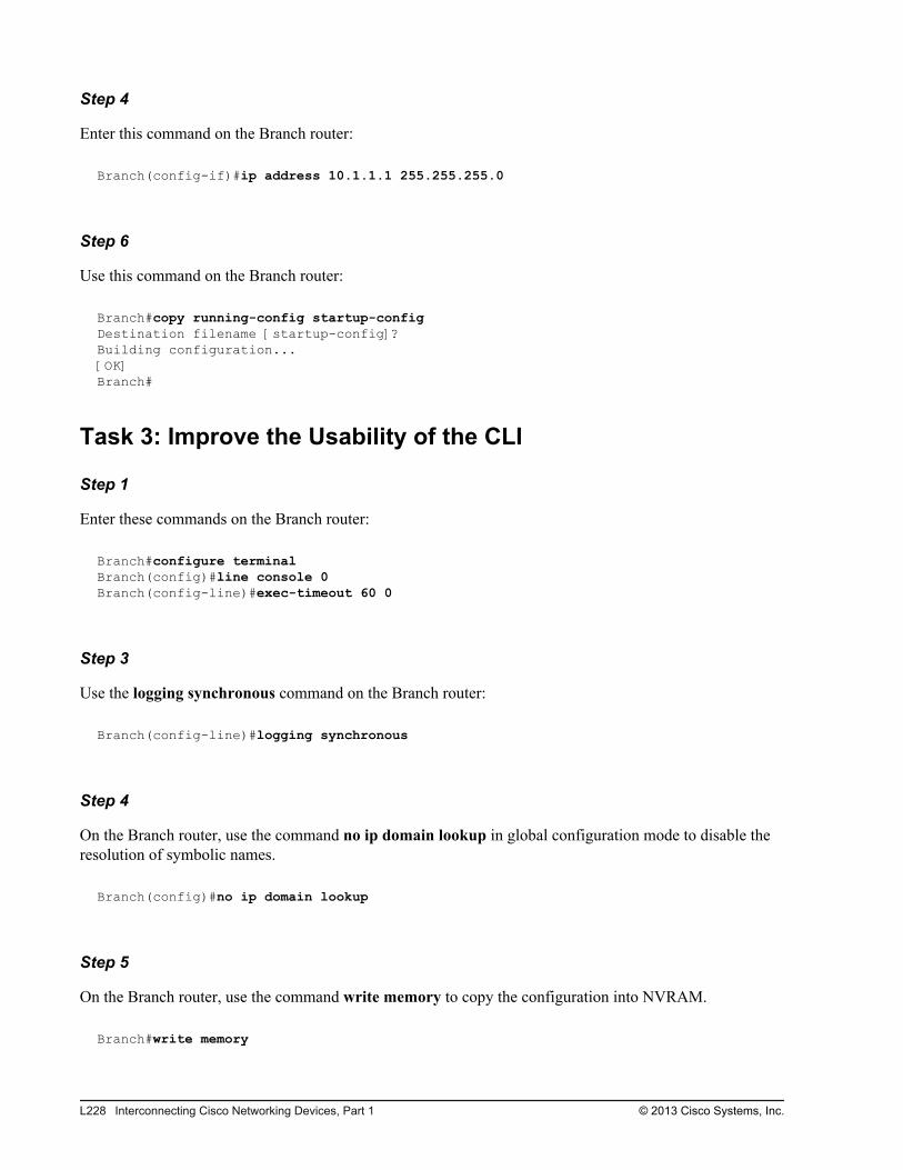
Step 4
Enter this command on the Branch router:
Branch(config-if)#ip address 10.1.1.1 255.255.255.0
Step 6
Use this command on the Branch router:
Branch#copy running-config startup-configDestination filename [startup-config]?Building configuration...[OK]Branch#
Task 3: Improve the Usability of the CLI
Step 1
Enter these commands on the Branch router:
Branch#configure terminalBranch(config)#line console 0Branch(config-line)#exec-timeout 60 0
Step 3
Use the logging synchronous command on the Branch router:
Branch(config-line)#logging synchronous
Step 4
On the Branch router, use the command no ip domain lookup in global configuration mode to disable theresolution of symbolic names.
Branch(config)#no ip domain lookup
Step 5
On the Branch router, use the command write memory to copy the configuration into NVRAM.
Branch#write memory
L228 Interconnecting Cisco Networking Devices, Part 1 © 2013 Cisco Systems, Inc.
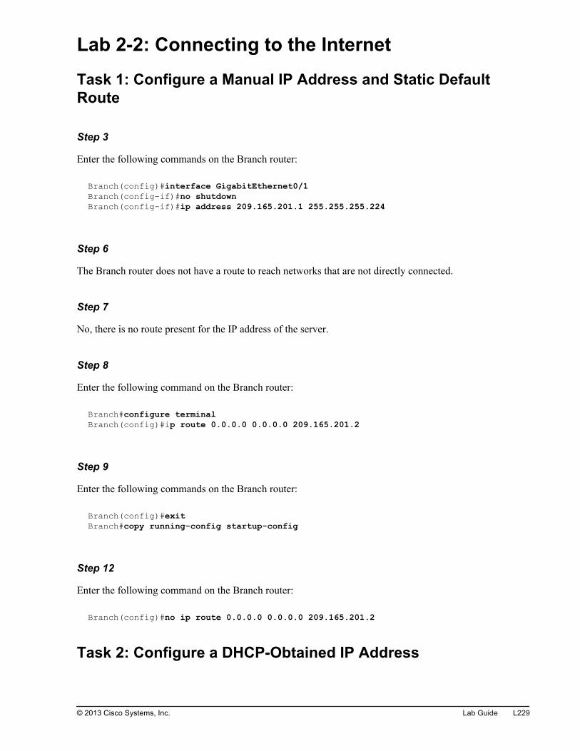
Lab 2-2: Connecting to the Internet
Task 1: Configure a Manual IP Address and Static DefaultRoute
Step 3
Enter the following commands on the Branch router:
Branch(config)#interface GigabitEthernet0/1Branch(config-if)#no shutdownBranch(config-if)#ip address 209.165.201.1 255.255.255.224
Step 6
The Branch router does not have a route to reach networks that are not directly connected.
Step 7
No, there is no route present for the IP address of the server.
Step 8
Enter the following command on the Branch router:
Branch#configure terminalBranch(config)#ip route 0.0.0.0 0.0.0.0 209.165.201.2
Step 9
Enter the following commands on the Branch router:
Branch(config)#exitBranch#copy running-config startup-config
Step 12
Enter the following command on the Branch router:
Branch(config)#no ip route 0.0.0.0 0.0.0.0 209.165.201.2
Task 2: Configure a DHCP-Obtained IP Address
© 2013 Cisco Systems, Inc. Lab Guide L229
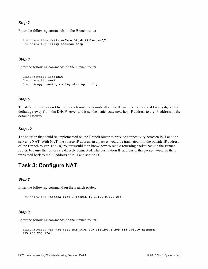
Step 2
Enter the following commands on the Branch router:
Branch(config-if)#interface GigabitEthernet0/1Branch(config-if)#ip address dhcp
Step 3
Enter the following commands on the Branch router:
Branch(config-if)#exitBranch(config)#exitBranch#copy running-config startup-config
Step 5
The default route was set by the Branch router automatically. The Branch router received knowledge of thedefault gateway from the DHCP server and it set the static route next-hop IP address to the IP address of thedefault gateway.
Step 12
The solution that could be implemented on the Branch router to provide connectivity between PC1 and theserver is NAT. With NAT, the source IP address in a packet would be translated into the outside IP addressof the Branch router. The HQ router would then know how to send a returning packet back to the Branchrouter, because the routers are directly connected. The destination IP address in the packet would be thentranslated back to the IP address of PC1 and sent to PC1.
Task 3: Configure NAT
Step 2
Enter the following command on the Branch router:
Branch(config)#access-list 1 permit 10.1.1.0 0.0.0.255
Step 3
Enter the following commands on the Branch router:
Branch(config)#ip nat pool NAT_POOL 209.165.201.5 209.165.201.10 netmask 255.255.255.224
L230 Interconnecting Cisco Networking Devices, Part 1 © 2013 Cisco Systems, Inc.
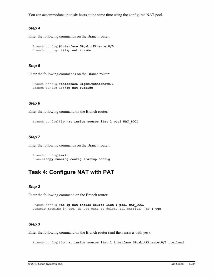
You can accommodate up to six hosts at the same time using the configured NAT pool.
Step 4
Enter the following commands on the Branch router:
Branch(config)#interface GigabitEthernet0/0Branch(config-if)#ip nat inside
Step 5
Enter the following commands on the Branch router:
Branch(config)#interface GigabitEthernet0/1Branch(config-if)#ip nat outside
Step 6
Enter the following command on the Branch router:
Branch(config)#ip nat inside source list 1 pool NAT_POOL
Step 7
Enter the following commands on the Branch router:
Branch(config)#exitBranch#copy running-config startup-config
Task 4: Configure NAT with PAT
Step 2
Enter the following command on the Branch router:
Branch(config)#no ip nat inside source list 1 pool NAT_POOLDynamic mapping in use, do you want to delete all entries? [no]: yes
Step 3
Enter the following command on the Branch router (and then answer with yes):
Branch(config)#ip nat inside source list 1 interface GigabitEthernet0/1 overload
© 2013 Cisco Systems, Inc. Lab Guide L231

You can accommodate approximately 64,000 hosts by overloading one IP address.
Step 4
Enter the following commands on the Branch router:
Branch(config)#exitBranch#copy running-config startup-config
Lab 3-1: Enhancing the Security of the InitialConfiguration
Task 1: Add Password Protection
Step 2
Enter this sequence of commands into the Branch router:
Branch> enableBranch# configure terminalBranch(config)# line console 0Branch(config-line)# password cisco Branch(config-line)# login
Step 5
Enter the following command sequence into the Branch router:
Branch(config)# username ccna secret ciscoBranch(config)# line console 0Branch(config-line)# login local
Step 8
Enter this sequence of commands into the Branch router:
Branch(config)# line vty 0 15Branch(config-line)# login local
Step 10
Enter this command on the Branch router:
Branch(config)# enable secret cisco
L232 Interconnecting Cisco Networking Devices, Part 1 © 2013 Cisco Systems, Inc.
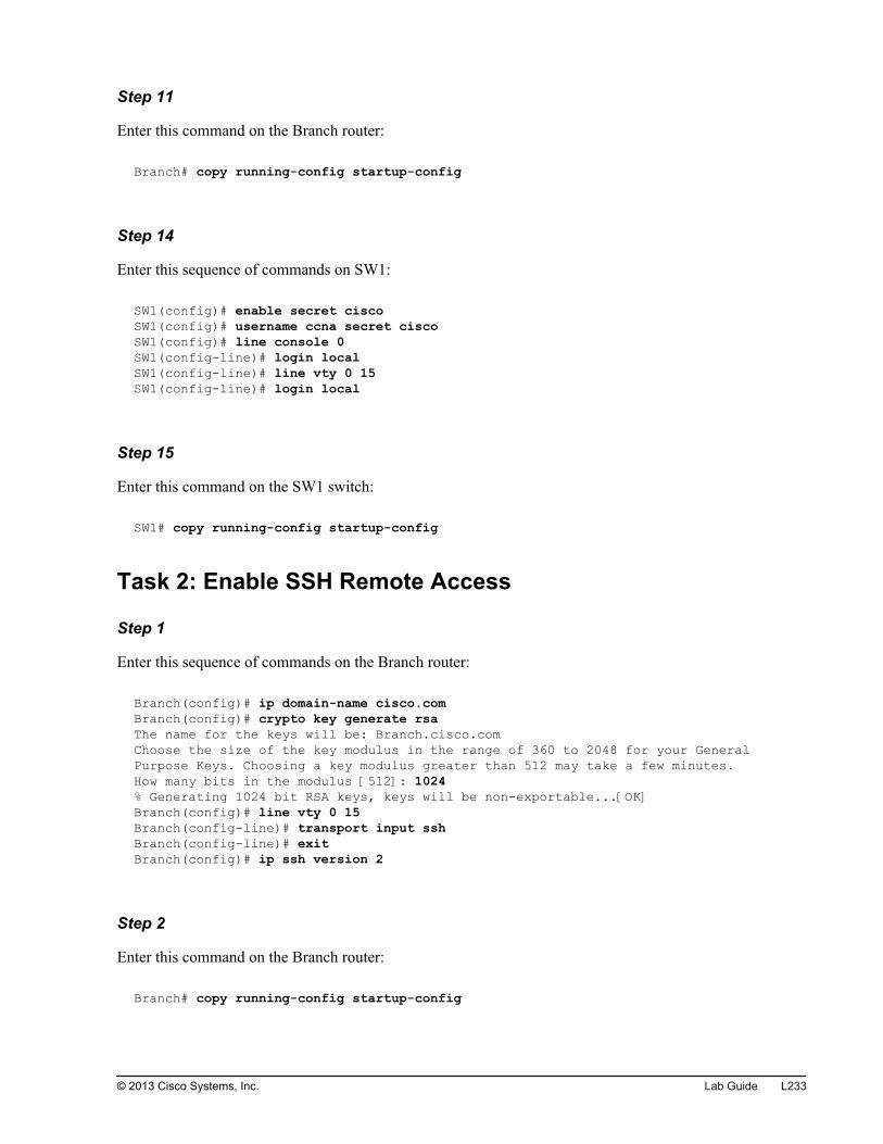
Step 11
Enter this command on the Branch router:
Branch# copy running-config startup-config
Step 14
Enter this sequence of commands on SW1:
SW1(config)# enable secret ciscoSW1(config)# username ccna secret ciscoSW1(config)# line console 0SW1(config-line)# login localSW1(config-line)# line vty 0 15SW1(config-line)# login local
Step 15
Enter this command on the SW1 switch:
SW1# copy running-config startup-config
Task 2: Enable SSH Remote Access
Step 1
Enter this sequence of commands on the Branch router:
Branch(config)# ip domain-name cisco.comBranch(config)# crypto key generate rsaThe name for the keys will be: Branch.cisco.comChoose the size of the key modulus in the range of 360 to 2048 for your General Purpose Keys. Choosing a key modulus greater than 512 may take a few minutes.How many bits in the modulus [512]: 1024% Generating 1024 bit RSA keys, keys will be non-exportable...[OK]Branch(config)# line vty 0 15Branch(config-line)# transport input sshBranch(config-line)# exitBranch(config)# ip ssh version 2
Step 2
Enter this command on the Branch router:
Branch# copy running-config startup-config
© 2013 Cisco Systems, Inc. Lab Guide L233
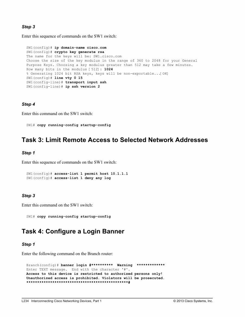
Step 3
Enter this sequence of commands on the SW1 switch:
SW1(config)# ip domain-name cisco.comSW1(config)# crypto key generate rsaThe name for the keys will be: SW1.cisco.comChoose the size of the key modulus in the range of 360 to 2048 for your General Purpose Keys. Choosing a key modulus greater than 512 may take a few minutes.How many bits in the modulus [512]: 1024% Generating 1024 bit RSA keys, keys will be non-exportable...[OK]SW1(config)# line vty 0 15SW1(config-line)# transport input sshSW1(config-line)# ip ssh version 2
Step 4
Enter this command on the SW1 switch:
SW1# copy running-config startup-config
Task 3: Limit Remote Access to Selected Network Addresses
Step 1
Enter this sequence of commands on the SW1 switch:
SW1(config)# access-list 1 permit host 10.1.1.1SW1(config)# access-list 1 deny any log
Step 3
Enter this command on the SW1 switch:
SW1# copy running-config startup-config
Task 4: Configure a Login Banner
Step 1
Enter the following command on the Branch router:
Branch(config)# banner login #********** Warning *************Enter TEXT message. End with the character '#'.Access to this device is restricted to authorized persons only!Unauthorized access is prohibited. Violators will be prosecuted.***********************************************#
L234 Interconnecting Cisco Networking Devices, Part 1 © 2013 Cisco Systems, Inc.
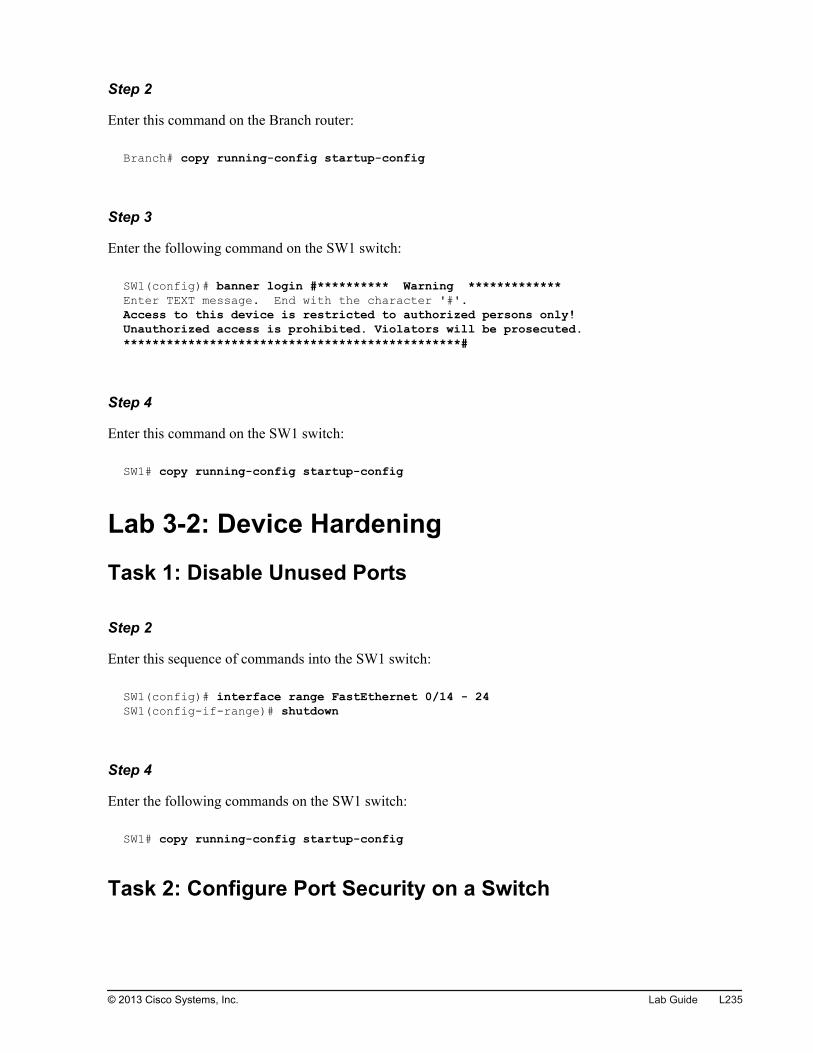
Step 2
Enter this command on the Branch router:
Branch# copy running-config startup-config
Step 3
Enter the following command on the SW1 switch:
SW1(config)# banner login #********** Warning *************Enter TEXT message. End with the character '#'.Access to this device is restricted to authorized persons only!Unauthorized access is prohibited. Violators will be prosecuted.***********************************************#
Step 4
Enter this command on the SW1 switch:
SW1# copy running-config startup-config
Lab 3-2: Device Hardening
Task 1: Disable Unused Ports
Step 2
Enter this sequence of commands into the SW1 switch:
SW1(config)# interface range FastEthernet 0/14 - 24SW1(config-if-range)# shutdown
Step 4
Enter the following commands on the SW1 switch:
SW1# copy running-config startup-config
Task 2: Configure Port Security on a Switch
© 2013 Cisco Systems, Inc. Lab Guide L235
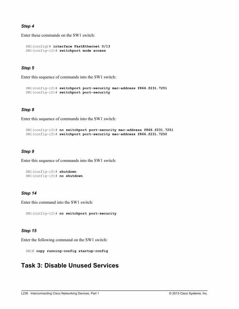
Step 4
Enter these commands on the SW1 switch:
SW1(config)# interface FastEthernet 0/13SW1(config-if)# switchport mode access
Step 5
Enter this sequence of commands into the SW1 switch:
SW1(config-if)# switchport port-security mac-address f866.f231.7251SW1(config-if)# switchport port-security
Step 8
Enter this sequence of commands into the SW1 switch:
SW1(config-if)# no switchport port-security mac-address f866.f231.7251SW1(config-if)# switchport port-security mac-address f866.f231.7250
Step 9
Enter this sequence of commands into the SW1 switch:
SW1(config-if)# shutdownSW1(config-if)# no shutdown
Step 14
Enter this command into the SW1 switch:
SW1(config-if)# no switchport port-security
Step 15
Enter the following command on the SW1 switch:
SW1# copy running-config startup-config
Task 3: Disable Unused Services
L236 Interconnecting Cisco Networking Devices, Part 1 © 2013 Cisco Systems, Inc.
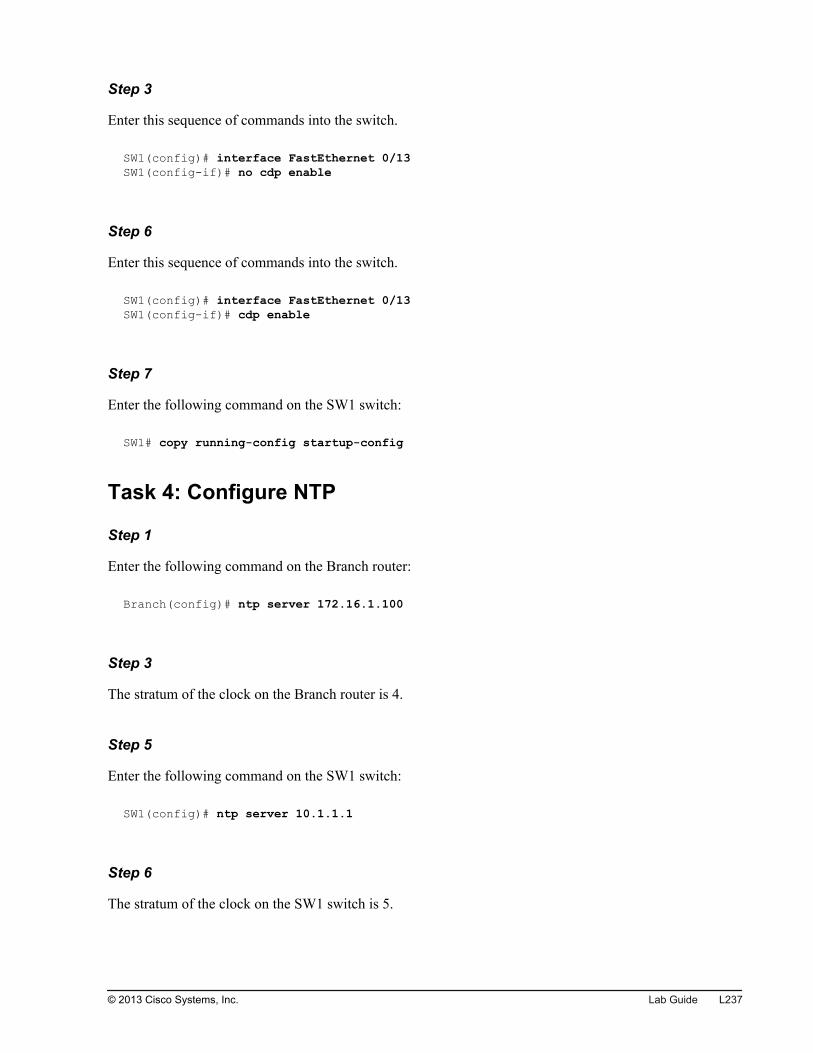
Step 3
Enter this sequence of commands into the switch.
SW1(config)# interface FastEthernet 0/13SW1(config-if)# no cdp enable
Step 6
Enter this sequence of commands into the switch.
SW1(config)# interface FastEthernet 0/13SW1(config-if)# cdp enable
Step 7
Enter the following command on the SW1 switch:
SW1# copy running-config startup-config
Task 4: Configure NTP
Step 1
Enter the following command on the Branch router:
Branch(config)# ntp server 172.16.1.100
Step 3
The stratum of the clock on the Branch router is 4.
Step 5
Enter the following command on the SW1 switch:
SW1(config)# ntp server 10.1.1.1
Step 6
The stratum of the clock on the SW1 switch is 5.
© 2013 Cisco Systems, Inc. Lab Guide L237

Step 7
Enter the following commands on the SW1 switch and Branch router:
SW1# copy running-config startup-config
Branch# copy running-config startup-config
Lab 3-3: Filtering Traffic with ACLs
Task 1: Configure an ACL
Step 2
Enter this sequence of commands into the Branch router:
Branch(config)# ip access-list extended TelnetBranch(config-ext-nacl)# deny tcp host 10.1.1.101 host 172.16.1.100 eq telnetBranch(config-ext-nacl)# permit ip any any
Step 4
Enter this sequence of commands into the Branch router:
Branch(config)# interface GigabitEthernet 0/0Branch(config-if)# ip access-group Telnet in
Step 6
Enter the following command on the Branch router:
Branch# copy running-config startup-config
Task 3: Troubleshoot an ACL
Step 7
Enter this sequence of commands into the Branch router:
Branch(config)# interface GigabitEthernet 0/0Branch(config-if)# no ip access-group outBranch(config-if)# ip access-group in
L238 Interconnecting Cisco Networking Devices, Part 1 © 2013 Cisco Systems, Inc.
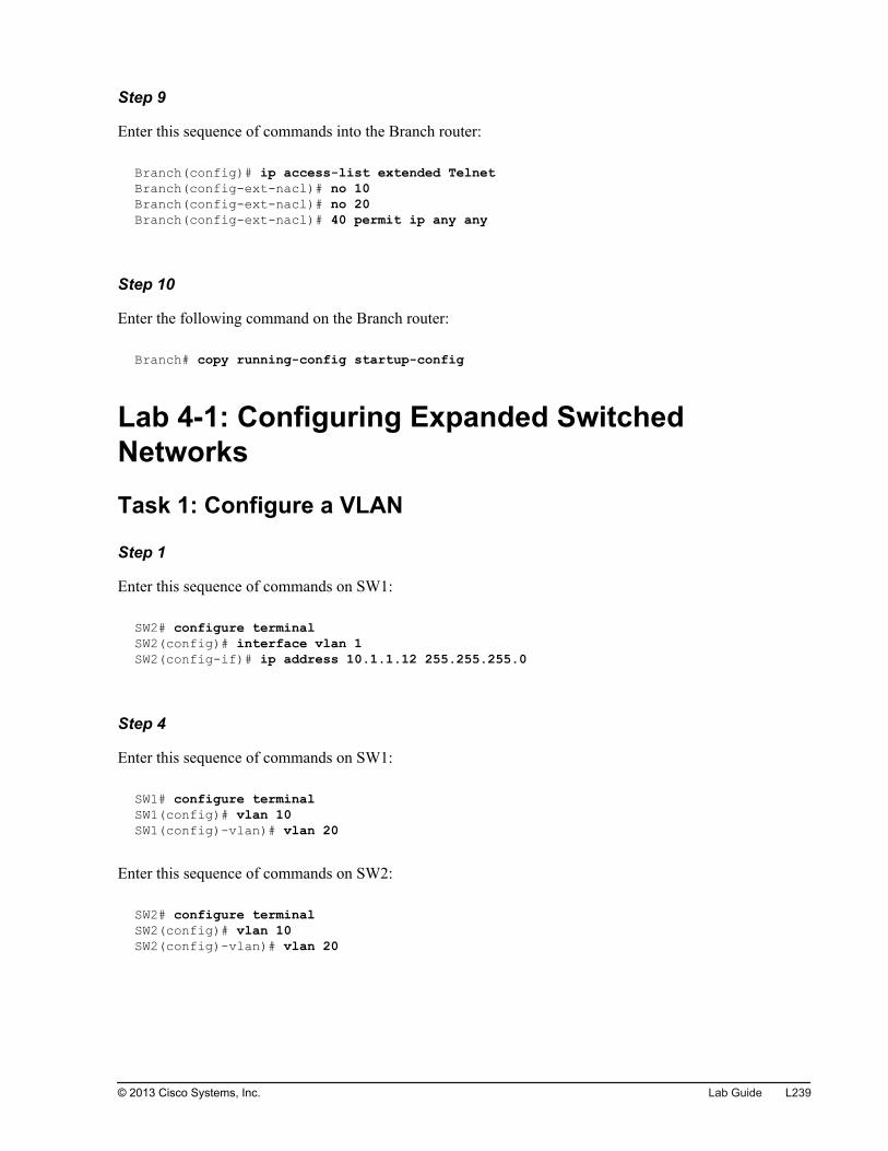
Step 9
Enter this sequence of commands into the Branch router:
Branch(config)# ip access-list extended TelnetBranch(config-ext-nacl)# no 10Branch(config-ext-nacl)# no 20Branch(config-ext-nacl)# 40 permit ip any any
Step 10
Enter the following command on the Branch router:
Branch# copy running-config startup-config
Lab 4-1: Configuring Expanded SwitchedNetworks
Task 1: Configure a VLAN
Step 1
Enter this sequence of commands on SW1:
SW2# configure terminalSW2(config)# interface vlan 1SW2(config-if)# ip address 10.1.1.12 255.255.255.0
Step 4
Enter this sequence of commands on SW1:
SW1# configure terminalSW1(config)# vlan 10SW1(config)-vlan)# vlan 20
Enter this sequence of commands on SW2:
SW2# configure terminalSW2(config)# vlan 10SW2(config)-vlan)# vlan 20
© 2013 Cisco Systems, Inc. Lab Guide L239
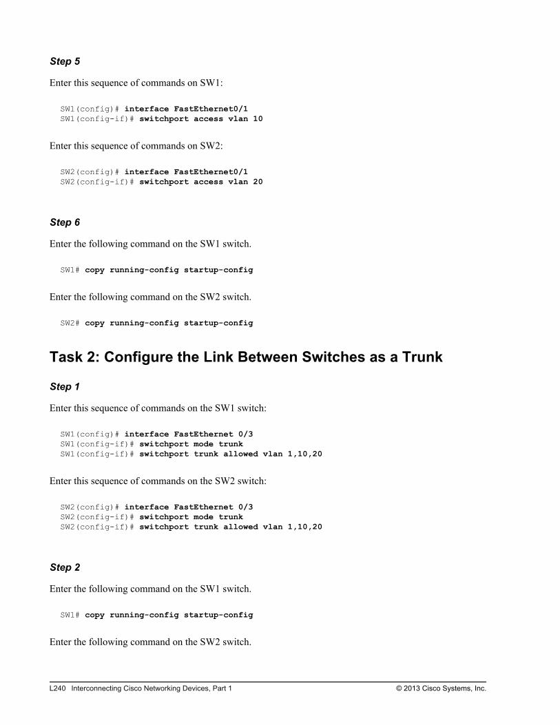
Step 5
Enter this sequence of commands on SW1:
SW1(config)# interface FastEthernet0/1SW1(config-if)# switchport access vlan 10
Enter this sequence of commands on SW2:
SW2(config)# interface FastEthernet0/1SW2(config-if)# switchport access vlan 20
Step 6
Enter the following command on the SW1 switch.
SW1# copy running-config startup-config
Enter the following command on the SW2 switch.
SW2# copy running-config startup-config
Task 2: Configure the Link Between Switches as a Trunk
Step 1
Enter this sequence of commands on the SW1 switch:
SW1(config)# interface FastEthernet 0/3SW1(config-if)# switchport mode trunkSW1(config-if)# switchport trunk allowed vlan 1,10,20
Enter this sequence of commands on the SW2 switch:
SW2(config)# interface FastEthernet 0/3SW2(config-if)# switchport mode trunkSW2(config-if)# switchport trunk allowed vlan 1,10,20
Step 2
Enter the following command on the SW1 switch.
SW1# copy running-config startup-config
Enter the following command on the SW2 switch.
L240 Interconnecting Cisco Networking Devices, Part 1 © 2013 Cisco Systems, Inc.
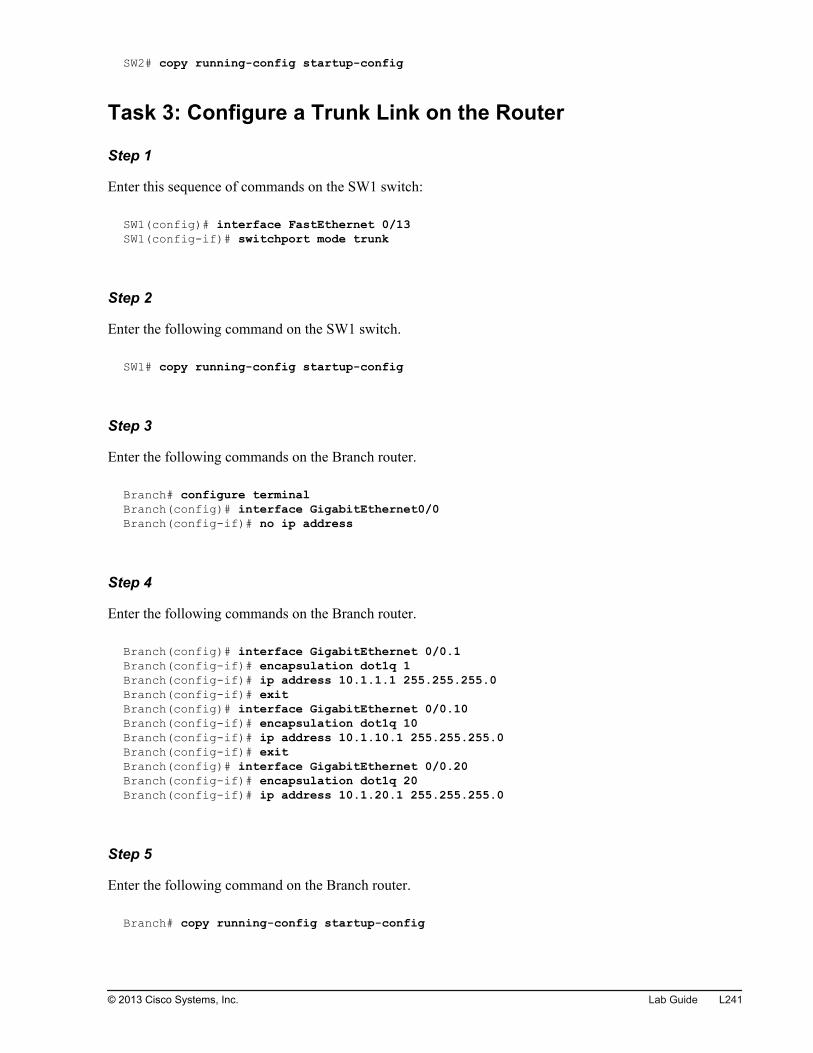
SW2# copy running-config startup-config
Task 3: Configure a Trunk Link on the Router
Step 1
Enter this sequence of commands on the SW1 switch:
SW1(config)# interface FastEthernet 0/13SW1(config-if)# switchport mode trunk
Step 2
Enter the following command on the SW1 switch.
SW1# copy running-config startup-config
Step 3
Enter the following commands on the Branch router.
Branch# configure terminalBranch(config)# interface GigabitEthernet0/0Branch(config-if)# no ip address
Step 4
Enter the following commands on the Branch router.
Branch(config)# interface GigabitEthernet 0/0.1Branch(config-if)# encapsulation dot1q 1Branch(config-if)# ip address 10.1.1.1 255.255.255.0Branch(config-if)# exitBranch(config)# interface GigabitEthernet 0/0.10Branch(config-if)# encapsulation dot1q 10Branch(config-if)# ip address 10.1.10.1 255.255.255.0Branch(config-if)# exitBranch(config)# interface GigabitEthernet 0/0.20Branch(config-if)# encapsulation dot1q 20Branch(config-if)# ip address 10.1.20.1 255.255.255.0
Step 5
Enter the following command on the Branch router.
Branch# copy running-config startup-config
© 2013 Cisco Systems, Inc. Lab Guide L241
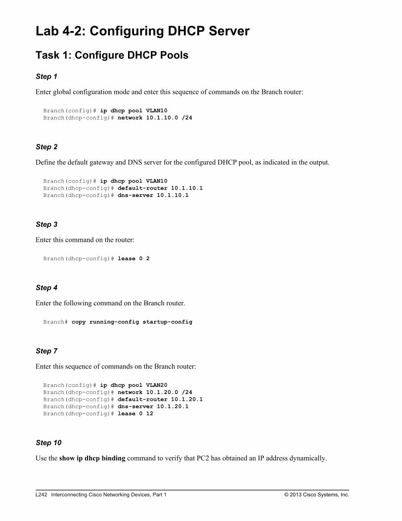
Lab 4-2: Configuring DHCP Server
Task 1: Configure DHCP Pools
Step 1
Enter global configuration mode and enter this sequence of commands on the Branch router:
Branch(config)# ip dhcp pool VLAN10Branch(dhcp-config)# network 10.1.10.0 /24
Step 2
Define the default gateway and DNS server for the configured DHCP pool, as indicated in the output.
Branch(config)# ip dhcp pool VLAN10Branch(dhcp-config)# default-router 10.1.10.1Branch(dhcp-config)# dns-server 10.1.10.1
Step 3
Enter this command on the router:
Branch(dhcp-config)# lease 0 2
Step 4
Enter the following command on the Branch router.
Branch# copy running-config startup-config
Step 7
Enter this sequence of commands on the Branch router:
Branch(config)# ip dhcp pool VLAN20Branch(dhcp-config)# network 10.1.20.0 /24Branch(dhcp-config)# default-router 10.1.20.1Branch(dhcp-config)# dns-server 10.1.20.1Branch(dhcp-config)# lease 0 12
Step 10
Use the show ip dhcp binding command to verify that PC2 has obtained an IP address dynamically.
L242 Interconnecting Cisco Networking Devices, Part 1 © 2013 Cisco Systems, Inc.
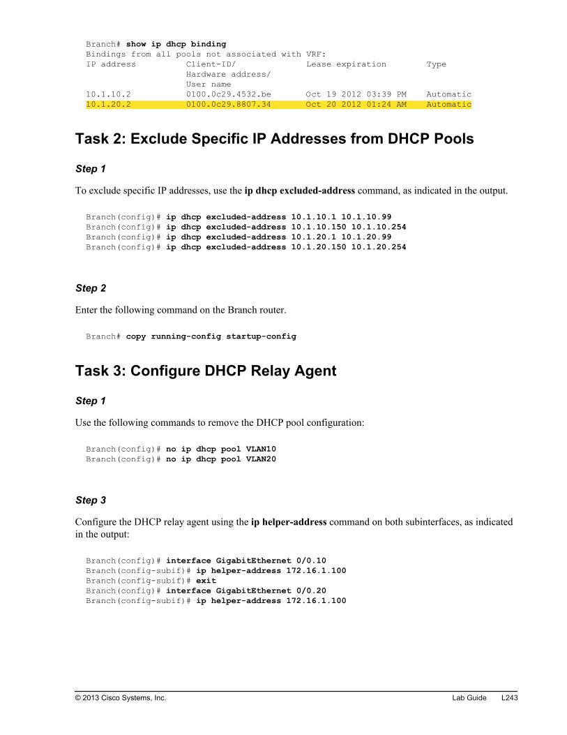
Branch# show ip dhcp bindingBindings from all pools not associated with VRF:IP address Client-ID/ Lease expiration Type Hardware address/ User name10.1.10.2 0100.0c29.4532.be Oct 19 2012 03:39 PM Automatic10.1.20.2 0100.0c29.8807.34 Oct 20 2012 01:24 AM Automatic
Task 2: Exclude Specific IP Addresses from DHCP Pools
Step 1
To exclude specific IP addresses, use the ip dhcp excluded-address command, as indicated in the output.
Branch(config)# ip dhcp excluded-address 10.1.10.1 10.1.10.99Branch(config)# ip dhcp excluded-address 10.1.10.150 10.1.10.254Branch(config)# ip dhcp excluded-address 10.1.20.1 10.1.20.99Branch(config)# ip dhcp excluded-address 10.1.20.150 10.1.20.254
Step 2
Enter the following command on the Branch router.
Branch# copy running-config startup-config
Task 3: Configure DHCP Relay Agent
Step 1
Use the following commands to remove the DHCP pool configuration:
Branch(config)# no ip dhcp pool VLAN10Branch(config)# no ip dhcp pool VLAN20
Step 3
Configure the DHCP relay agent using the ip helper-address command on both subinterfaces, as indicatedin the output:
Branch(config)# interface GigabitEthernet 0/0.10Branch(config-subif)# ip helper-address 172.16.1.100Branch(config-subif)# exitBranch(config)# interface GigabitEthernet 0/0.20Branch(config-subif)# ip helper-address 172.16.1.100
© 2013 Cisco Systems, Inc. Lab Guide L243
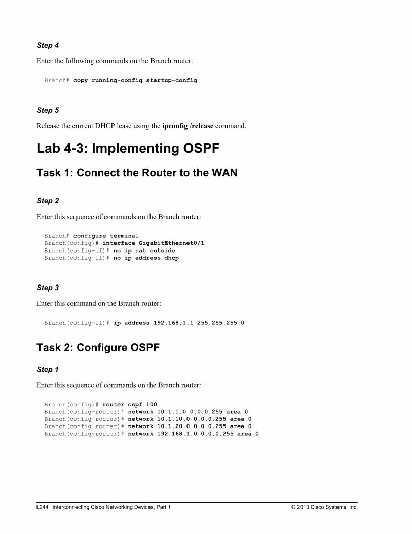
Step 4
Enter the following commands on the Branch router.
Branch# copy running-config startup-config
Step 5
Release the current DHCP lease using the ipconfig /release command.
Lab 4-3: Implementing OSPF
Task 1: Connect the Router to the WAN
Step 2
Enter this sequence of commands on the Branch router:
Branch# configure terminalBranch(config)# interface GigabitEthernet0/1Branch(config-if)# no ip nat outsideBranch(config-if)# no ip address dhcp
Step 3
Enter this command on the Branch router:
Branch(config-if)# ip address 192.168.1.1 255.255.255.0
Task 2: Configure OSPF
Step 1
Enter this sequence of commands on the Branch router:
Branch(config)# router ospf 100Branch(config-router)# network 10.1.1.0 0.0.0.255 area 0Branch(config-router)# network 10.1.10.0 0.0.0.255 area 0Branch(config-router)# network 10.1.20.0 0.0.0.255 area 0Branch(config-router)# network 192.168.1.0 0.0.0.255 area 0
L244 Interconnecting Cisco Networking Devices, Part 1 © 2013 Cisco Systems, Inc.

Lab 5-1: Configure and Verify Basic IPv6
Task 1: Enable IPv6 on the Router
Step 1
Enter this command on the Branch router:
Branch(config)# ipv6 unicast-routing
Step 2
Enter these commands on the Branch router:
Branch(config)# interface GigabitEthernet 0/1Branch(config-if)# ipv6 address 2001:db8:D1A5:C900::1/64
Step 3
Enter the following command on the Branch router:
Branch# copy running-config startup-config
Lab 5-2: Configure and Verify StatelessAutoconfiguration
Task 1: Enable Stateless Autoconfiguration on the Router
Step 2
Enter these commands on the Branch router:
Branch(config)# interface GigabitEthernet 0/1Branch(config-if)# no ipv6 address 2001:DB8:D1A5:C900::1/64
Step 3
Enter these commands on the Branch router:
Branch(config)# interface GigabitEthernet 0/1Branch(config-if)# ipv6 address autoconfig
© 2013 Cisco Systems, Inc. Lab Guide L245
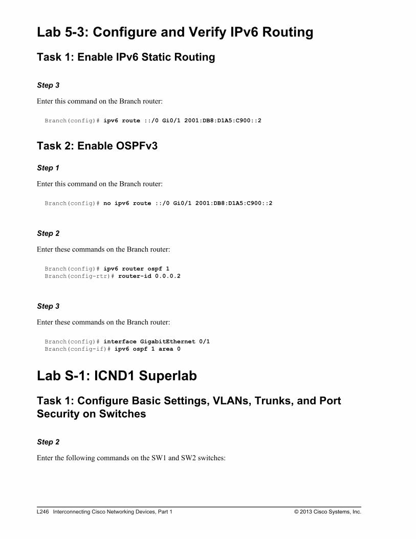
Lab 5-3: Configure and Verify IPv6 Routing
Task 1: Enable IPv6 Static Routing
Step 3
Enter this command on the Branch router:
Branch(config)# ipv6 route ::/0 Gi0/1 2001:DB8:D1A5:C900::2
Task 2: Enable OSPFv3
Step 1
Enter this command on the Branch router:
Branch(config)# no ipv6 route ::/0 Gi0/1 2001:DB8:D1A5:C900::2
Step 2
Enter these commands on the Branch router:
Branch(config)# ipv6 router ospf 1Branch(config-rtr)# router-id 0.0.0.2
Step 3
Enter these commands on the Branch router:
Branch(config)# interface GigabitEthernet 0/1Branch(config-if)# ipv6 ospf 1 area 0
Lab S-1: ICND1 Superlab
Task 1: Configure Basic Settings, VLANs, Trunks, and PortSecurity on Switches
Step 2
Enter the following commands on the SW1 and SW2 switches:
L246 Interconnecting Cisco Networking Devices, Part 1 © 2013 Cisco Systems, Inc.
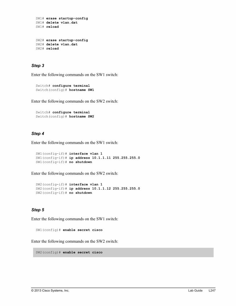
SW1# erase startup-configSW1# delete vlan.datSW1# reload
SW2# erase startup-configSW2# delete vlan.datSW2# reload
Step 3
Enter the following commands on the SW1 switch:
Switch# configure terminal Switch(config)# hostname SW1
Enter the following commands on the SW2 switch:
Switch# configure terminal Switch(config)# hostname SW2
Step 4
Enter the following commands on the SW1 switch:
SW1(config-if)# interface vlan 1SW1(config-if)# ip address 10.1.1.11 255.255.255.0SW1(config-if)# no shutdown
Enter the following commands on the SW2 switch:
SW2(config-if)# interface vlan 1SW2(config-if)# ip address 10.1.1.12 255.255.255.0SW2(config-if)# no shutdown
Step 5
Enter the following commands on the SW1 switch:
SW1(config)# enable secret cisco
Enter the following commands on the SW2 switch:
SW2(config)# enable secret cisco
© 2013 Cisco Systems, Inc. Lab Guide L247
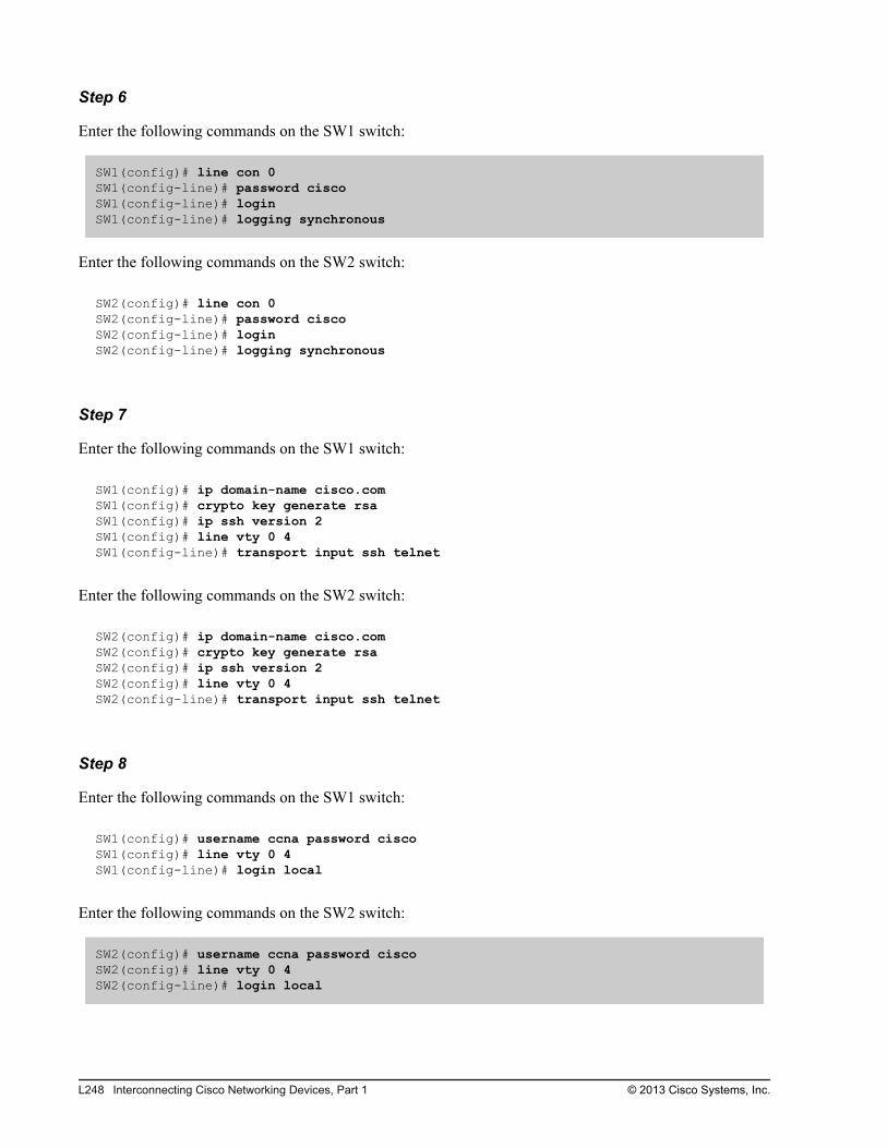
Step 6
Enter the following commands on the SW1 switch:
SW1(config)# line con 0SW1(config-line)# password ciscoSW1(config-line)# loginSW1(config-line)# logging synchronous
Enter the following commands on the SW2 switch:
SW2(config)# line con 0SW2(config-line)# password ciscoSW2(config-line)# loginSW2(config-line)# logging synchronous
Step 7
Enter the following commands on the SW1 switch:
SW1(config)# ip domain-name cisco.comSW1(config)# crypto key generate rsa SW1(config)# ip ssh version 2SW1(config)# line vty 0 4SW1(config-line)# transport input ssh telnet
Enter the following commands on the SW2 switch:
SW2(config)# ip domain-name cisco.comSW2(config)# crypto key generate rsa SW2(config)# ip ssh version 2SW2(config)# line vty 0 4SW2(config-line)# transport input ssh telnet
Step 8
Enter the following commands on the SW1 switch:
SW1(config)# username ccna password ciscoSW1(config)# line vty 0 4SW1(config-line)# login local
Enter the following commands on the SW2 switch:
SW2(config)# username ccna password ciscoSW2(config)# line vty 0 4SW2(config-line)# login local
L248 Interconnecting Cisco Networking Devices, Part 1 © 2013 Cisco Systems, Inc.
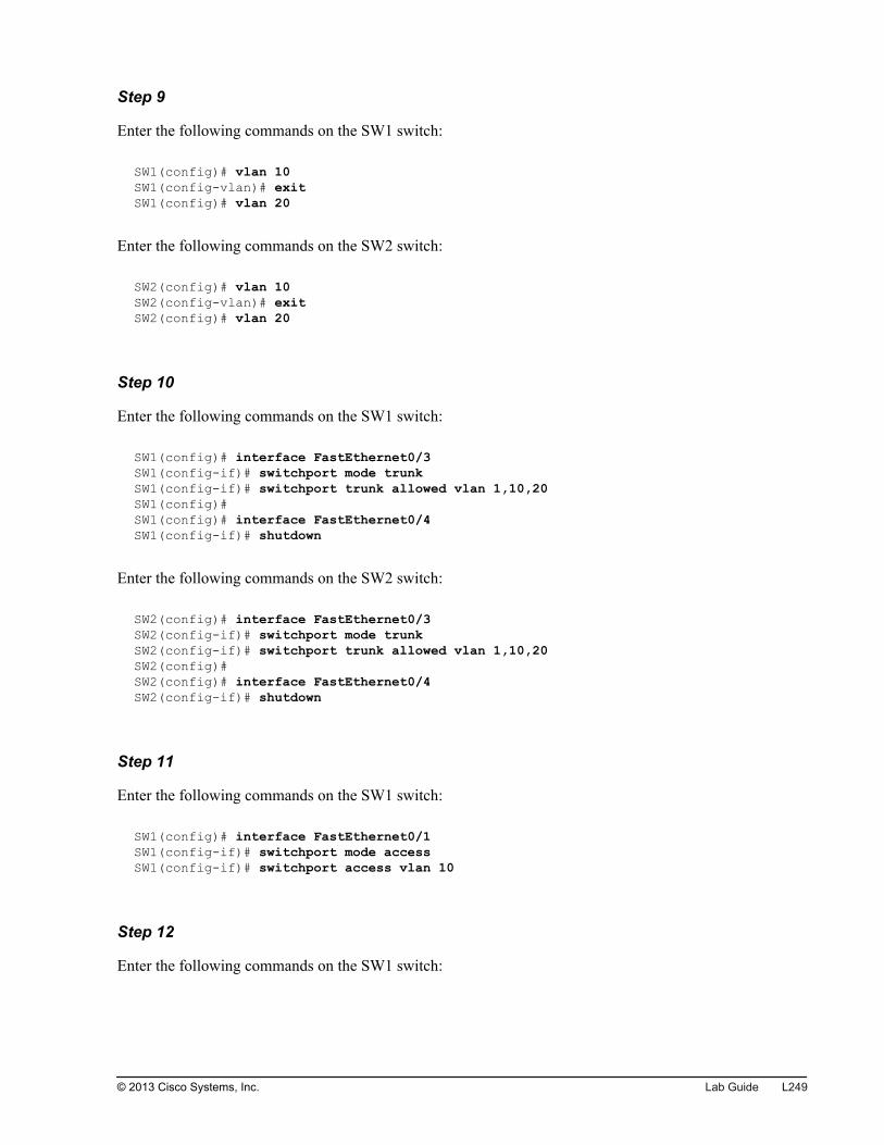
Step 9
Enter the following commands on the SW1 switch:
SW1(config)# vlan 10SW1(config-vlan)# exitSW1(config)# vlan 20
Enter the following commands on the SW2 switch:
SW2(config)# vlan 10SW2(config-vlan)# exitSW2(config)# vlan 20
Step 10
Enter the following commands on the SW1 switch:
SW1(config)# interface FastEthernet0/3SW1(config-if)# switchport mode trunk SW1(config-if)# switchport trunk allowed vlan 1,10,20SW1(config)#SW1(config)# interface FastEthernet0/4SW1(config-if)# shutdown
Enter the following commands on the SW2 switch:
SW2(config)# interface FastEthernet0/3SW2(config-if)# switchport mode trunk SW2(config-if)# switchport trunk allowed vlan 1,10,20SW2(config)#SW2(config)# interface FastEthernet0/4SW2(config-if)# shutdown
Step 11
Enter the following commands on the SW1 switch:
SW1(config)# interface FastEthernet0/1SW1(config-if)# switchport mode accessSW1(config-if)# switchport access vlan 10
Step 12
Enter the following commands on the SW1 switch:
© 2013 Cisco Systems, Inc. Lab Guide L249
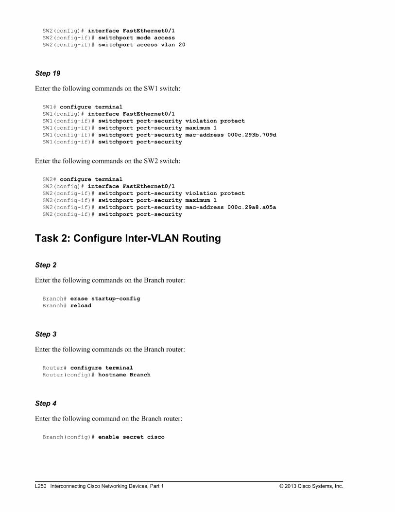
SW2(config)# interface FastEthernet0/1SW2(config-if)# switchport mode accessSW2(config-if)# switchport access vlan 20
Step 19
Enter the following commands on the SW1 switch:
SW1# configure terminalSW1(config)# interface FastEthernet0/1SW1(config-if)# switchport port-security violation protect SW1(config-if)# switchport port-security maximum 1SW1(config-if)# switchport port-security mac-address 000c.293b.709dSW1(config-if)# switchport port-security
Enter the following commands on the SW2 switch:
SW2# configure terminalSW2(config)# interface FastEthernet0/1SW2(config-if)# switchport port-security violation protect SW2(config-if)# switchport port-security maximum 1 SW2(config-if)# switchport port-security mac-address 000c.29a8.a05aSW2(config-if)# switchport port-security
Task 2: Configure Inter-VLAN Routing
Step 2
Enter the following commands on the Branch router:
Branch# erase startup-configBranch# reload
Step 3
Enter the following commands on the Branch router:
Router# configure terminal Router(config)# hostname Branch
Step 4
Enter the following command on the Branch router:
Branch(config)# enable secret cisco
L250 Interconnecting Cisco Networking Devices, Part 1 © 2013 Cisco Systems, Inc.
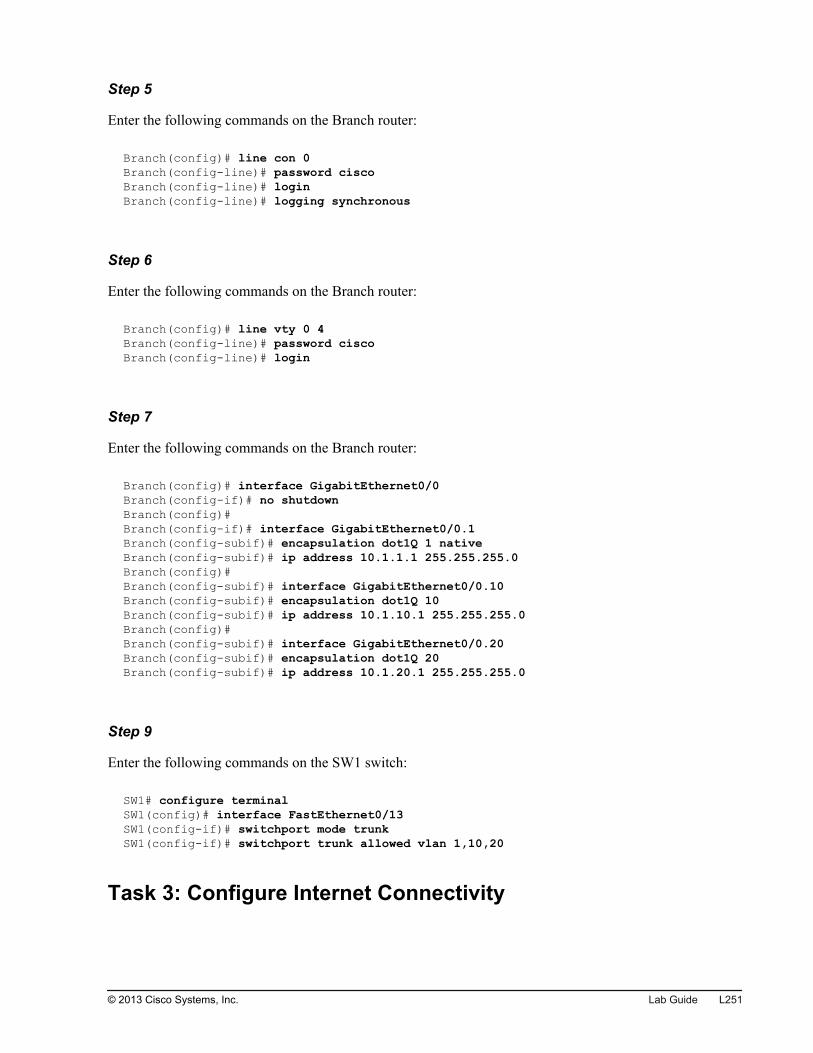
Step 5
Enter the following commands on the Branch router:
Branch(config)# line con 0Branch(config-line)# password ciscoBranch(config-line)# loginBranch(config-line)# logging synchronous
Step 6
Enter the following commands on the Branch router:
Branch(config)# line vty 0 4Branch(config-line)# password ciscoBranch(config-line)# login
Step 7
Enter the following commands on the Branch router:
Branch(config)# interface GigabitEthernet0/0Branch(config-if)# no shutdownBranch(config)#Branch(config-if)# interface GigabitEthernet0/0.1Branch(config-subif)# encapsulation dot1Q 1 nativeBranch(config-subif)# ip address 10.1.1.1 255.255.255.0Branch(config)#Branch(config-subif)# interface GigabitEthernet0/0.10 Branch(config-subif)# encapsulation dot1Q 10 Branch(config-subif)# ip address 10.1.10.1 255.255.255.0Branch(config)#Branch(config-subif)# interface GigabitEthernet0/0.20 Branch(config-subif)# encapsulation dot1Q 20 Branch(config-subif)# ip address 10.1.20.1 255.255.255.0
Step 9
Enter the following commands on the SW1 switch:
SW1# configure terminalSW1(config)# interface FastEthernet0/13SW1(config-if)# switchport mode trunkSW1(config-if)# switchport trunk allowed vlan 1,10,20
Task 3: Configure Internet Connectivity
© 2013 Cisco Systems, Inc. Lab Guide L251
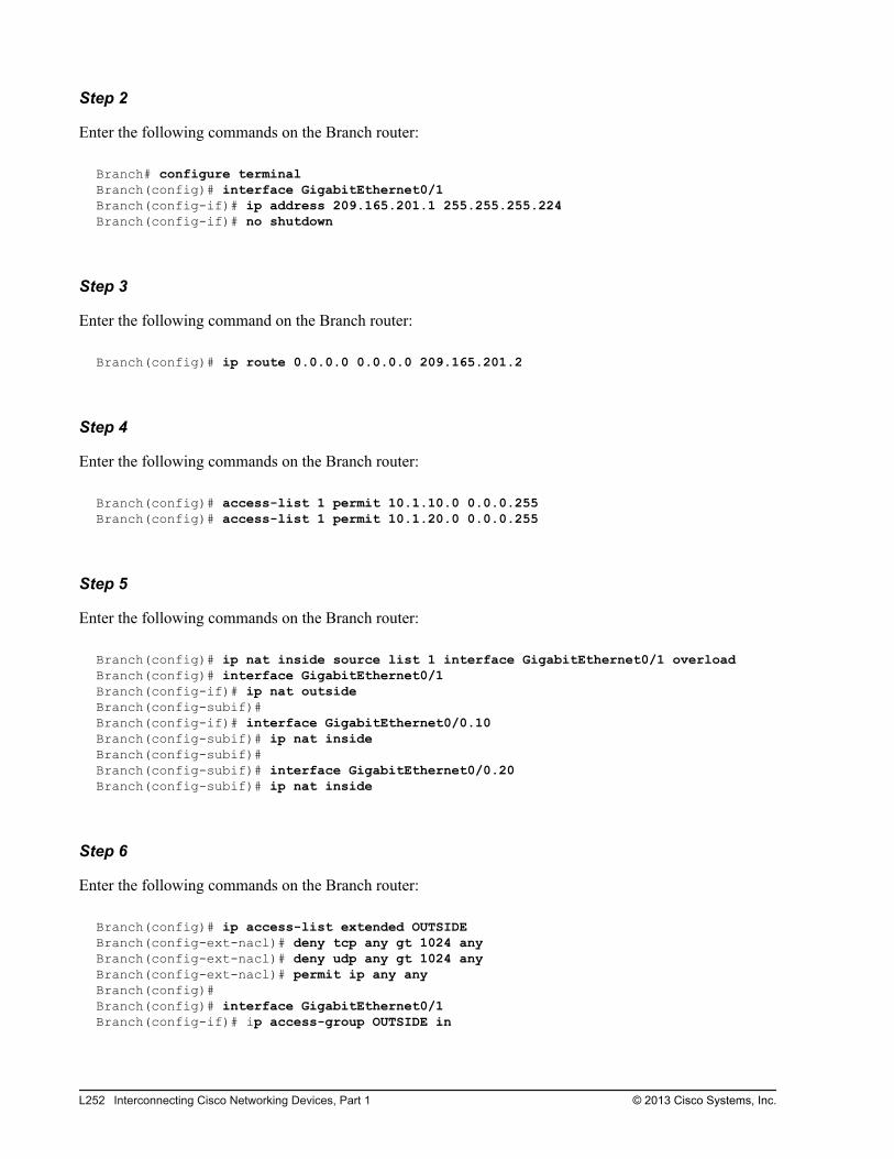
Step 2
Enter the following commands on the Branch router:
Branch# configure terminal Branch(config)# interface GigabitEthernet0/1Branch(config-if)# ip address 209.165.201.1 255.255.255.224Branch(config-if)# no shutdown
Step 3
Enter the following command on the Branch router:
Branch(config)# ip route 0.0.0.0 0.0.0.0 209.165.201.2
Step 4
Enter the following commands on the Branch router:
Branch(config)# access-list 1 permit 10.1.10.0 0.0.0.255Branch(config)# access-list 1 permit 10.1.20.0 0.0.0.255
Step 5
Enter the following commands on the Branch router:
Branch(config)# ip nat inside source list 1 interface GigabitEthernet0/1 overloadBranch(config)# interface GigabitEthernet0/1Branch(config-if)# ip nat outside Branch(config-subif)#Branch(config-if)# interface GigabitEthernet0/0.10Branch(config-subif)# ip nat inside Branch(config-subif)#Branch(config-subif)# interface GigabitEthernet0/0.20Branch(config-subif)# ip nat inside
Step 6
Enter the following commands on the Branch router:
Branch(config)# ip access-list extended OUTSIDEBranch(config-ext-nacl)# deny tcp any gt 1024 any Branch(config-ext-nacl)# deny udp any gt 1024 any Branch(config-ext-nacl)# permit ip any any Branch(config)#Branch(config)# interface GigabitEthernet0/1Branch(config-if)# ip access-group OUTSIDE in
L252 Interconnecting Cisco Networking Devices, Part 1 © 2013 Cisco Systems, Inc.
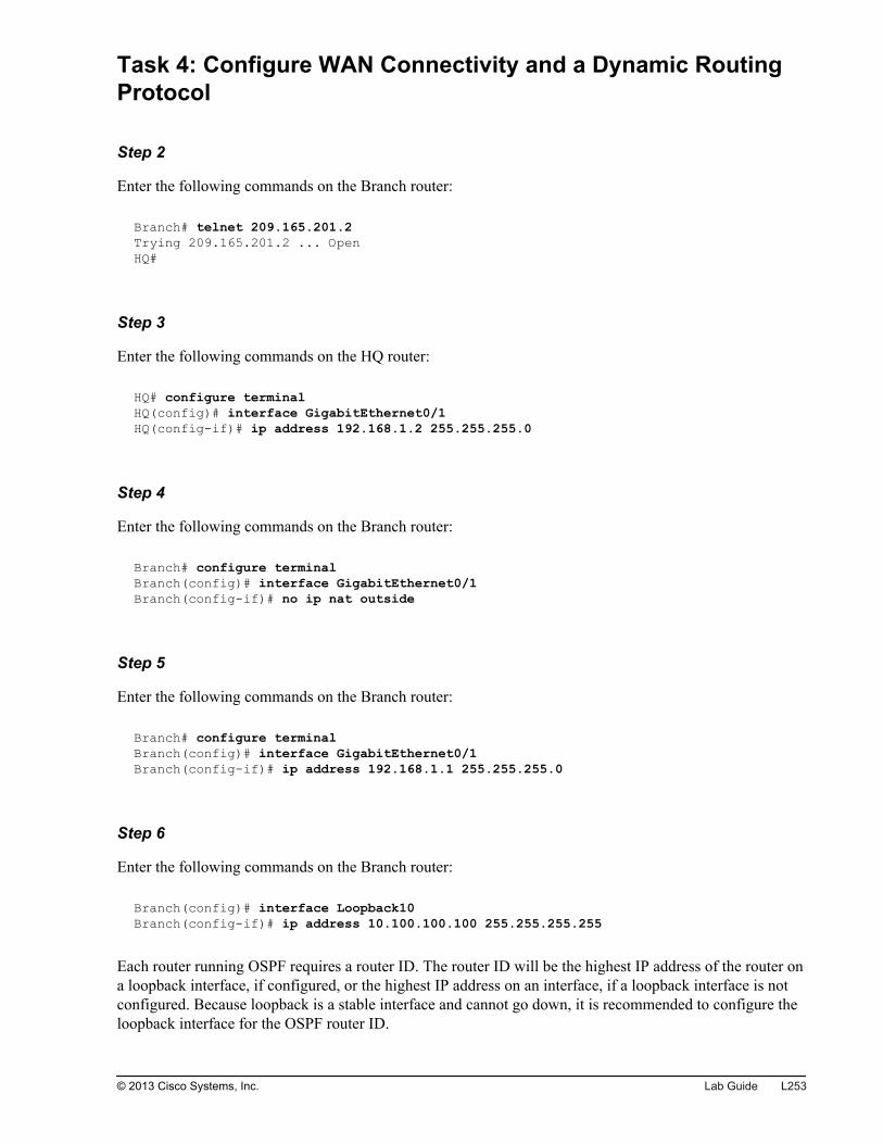
Task 4: Configure WAN Connectivity and a Dynamic RoutingProtocol
Step 2
Enter the following commands on the Branch router:
Branch# telnet 209.165.201.2Trying 209.165.201.2 ... OpenHQ#
Step 3
Enter the following commands on the HQ router:
HQ# configure terminalHQ(config)# interface GigabitEthernet0/1HQ(config-if)# ip address 192.168.1.2 255.255.255.0
Step 4
Enter the following commands on the Branch router:
Branch# configure terminal Branch(config)# interface GigabitEthernet0/1Branch(config-if)# no ip nat outside
Step 5
Enter the following commands on the Branch router:
Branch# configure terminal Branch(config)# interface GigabitEthernet0/1Branch(config-if)# ip address 192.168.1.1 255.255.255.0
Step 6
Enter the following commands on the Branch router:
Branch(config)# interface Loopback10Branch(config-if)# ip address 10.100.100.100 255.255.255.255
Each router running OSPF requires a router ID. The router ID will be the highest IP address of the router ona loopback interface, if configured, or the highest IP address on an interface, if a loopback interface is notconfigured. Because loopback is a stable interface and cannot go down, it is recommended to configure theloopback interface for the OSPF router ID.
© 2013 Cisco Systems, Inc. Lab Guide L253

Step 7
Enter the following command on the Branch router:
Branch(config)# router ospf 1
Step 8
Enter the following commands on the Branch router:
Branch(config-router)# network 192.168.1.0 0.0.0.255 area 0Branch(config-router)# network 10.1.1.0 0.0.0.255 area 0 Branch(config-router)# network 10.1.10.0 0.0.0.255 area 0Branch(config-router)# network 10.1.20.0 0.0.0.255 area 0Branch(config-router)# network 10.100.100.100 0.0.0.0 area 0
Task 5: Configure IPv6 Connectivity in the LAN
Step 2
Enter the following commands on the Branch router:
Branch# configure terminal Branch(config)# ipv6 unicast-routing
Step 3
Enter the following commands on the Branch router:
Branch(config-if)# interface GigabitEthernet0/0.1Branch(config-subif)# ipv6 address 2001:db8:0A01:100::1/64 Branch(config)#Branch(config-subif)# interface GigabitEthernet0/0.10 Branch(config-subif)# ipv6 address 2001:db8:0A01:A00::1/64Branch(config)#Branch(config-subif)# interface GigabitEthernet0/0.20 Branch(config-subif)# ipv6 address 2001:db8:0A01:1400::1/64
Step 1
The link-local IPv6 address is the same on all subinterfaces because the link-local IPv6 address is derivedfrom the MAC address, which is the same on all subinterfaces. All subinterfaces use the MAC address ofthe physical interface.
L254 Interconnecting Cisco Networking Devices, Part 1 © 2013 Cisco Systems, Inc.
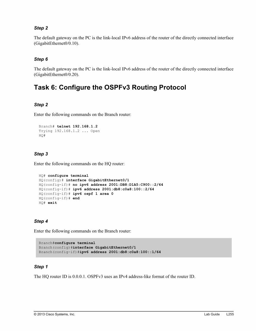
Step 2
The default gateway on the PC is the link-local IPv6 address of the router of the directly connected interface(GigabitEthernet0/0.10).
Step 6
The default gateway on the PC is the link-local IPv6 address of the router of the directly connected interface(GigabitEthernet0/0.20).
Task 6: Configure the OSPFv3 Routing Protocol
Step 2
Enter the following commands on the Branch router:
Branch# telnet 192.168.1.2Trying 192.168.1.2 ... OpenHQ#
Step 3
Enter the following commands on the HQ router:
HQ# configure terminalHQ(config)# interface GigabitEthernet0/1HQ(config-if)# no ipv6 address 2001:DB8:D1A5:C900::2/64HQ(config-if)# ipv6 address 2001:db8:c0a8:100::2/64HQ(config-if)# ipv6 ospf 1 area 0 HQ(config-if)# endHQ# exit
Step 4
Enter the following commands on the Branch router:
Branch#configure terminal Branch(config)#interface GigabitEthernet0/1Branch(config-if)#ipv6 address 2001:db8:c0a8:100::1/64
Step 1
The HQ router ID is 0.0.0.1. OSPFv3 uses an IPv4 address-like format of the router ID.
© 2013 Cisco Systems, Inc. Lab Guide L255

Step 2
The Branch router ID is 10.100.100.100, which is the IPv4 address on the Loopback0 interface. OSPFv3uses the same mechanisms as OSPF to determine the router ID.
L256 Interconnecting Cisco Networking Devices, Part 1 © 2013 Cisco Systems, Inc.