Part 1 Aircraft and Instrumentation in Atmospheric...
63
NCAR-TN-6 (revised) ALLY~ Aircraft and Instrumentation In Atmospheric Research FACILITIES LABORATORY October 1970 - o/ a4 v-Ao . (I Aj' WA LIBRARYAa 5DEC 4 1970 i,:,--- _,R 'echnica N1ote0s, : NATIONA^TEER FOR ATMOSPHERIC RESEARCH :.. Boulder, Colorado ::.·n L ">gtogg :
Transcript of Part 1 Aircraft and Instrumentation in Atmospheric...

NCAR-TN-6 (revised) ALLY~
Aircraft and InstrumentationIn Atmospheric Research
FACILITIES LABORATORY
October 1970 - o/ a4 v-Ao .
(I Aj'
WA LIBRARYAa
5DEC 4 1970
i,:,--- _,R 'echnica N1ote0s, :NATIONA^TEER FOR ATMOSPHERIC RESEARCH :..
Boulder, Colorado
::.·n L ">gtogg :

The National Center for Atmospheric Research (NCAR) is dedicated to the advancement of theatmospheric sciences for the benefit of mankind. It is operated by the University Corporation forAtmospheric Research (UCAR), a private, university controlled, nonprofit organization, and is sponsoredand principally funded by the National Science Foundation.
NCAR shares with other atmospheric research groups four interrelated, long-range objectives thatprovide justification for major expenditures of public and private funds:
* To ascertain the feasibility of controlling weather and climate, to develop the techniques forcontrol, and to bring about the beneficial application of this knowledge;
* To bring about improved description and prediction of astrophysical influences on the atmosphereand the space environment of our planet;
* To bring about improved description and prediction of atmospheric processes and the forecastingof weather and climate;
* To improve our understanding of the sources of air contamination and to bring about theapplication of better practices of air conservation.
The research and facilities operation of NCAR are conducted in four organizational entities:
The Laboratory of Atmospheric ScienceThe High Altitude ObservatoryThe Facilities LaboratoryThe Advanced Study Program
All visiting scientist programs and joint-use facilities of NCAR are available to scientists from UCARmember and non-member institutions (including private and government laboratories in the United Statesand abroad) on an equal basis. The member universities of UCAR are:
University of Alaska Florida State University New York University
University of Arizona University of Hawaii University of Oklahoma
University of California The Johns Hopkins University Pennsylvania State University
The Catholic University of America University of Maryland Saint Louis University
University of Chicago Massachusetts Institute of Technology Texas A & M University
Colorado State University University of Miami University of Texas
University of Colorado University of Michigan University of Utah
Cornell University University of Minnesota University of Washington
University of Denver University of Missouri University of Wisconsin

iii
PREFACE
The purpose of this catalog is to provide convenient and reasonablycomprehensive information on aircraft and associated instrumentationused for atmospheric research in the United States. The catalog shouldmake possible more efficient access to, and use of, such aircraft byinterested research scientists.
The information presented here was originally compiled by E. BollayAssociates, Inc., under subcontract to the NCAR Research Aviation Facil-ity. The Facility, established in March 1964 within the Facilities Lab-oratory of the National Center for Atmospheric Research (NCAR), is in-
tended for joint use by NCAR staff members, and university and otherresearch scientists not with NCAR. The Facility provides aviationservices to a variety of atmospheric research programs and, in addition,has been designated by the Interdepartmental Committee for the Atmo-spheric Sciences (a committee of the Federal Council for Science andTechnology) to serve as a nationwide center for collecting and dissemi-
nating information on atmospheric research aircraft, and their instru-mentation. This catalog was prepared as part of the Facility'sinformation-exchange program.
The Facility supports flight research, provides technical assis-tance in developing aircraft instrumentation and data recording andreduction systems, serves as a liaison between the scientific communityand Federal regulatory bodies, and trains scientific and technical work-ers in the use of aircraft for research.
This loose-leaf catalog will be updated by replacing obsoletesections, or by issuing additional pages to include new data. Catalogholders will receive such correction sheets as soon as they are issued.
The organizations listed in the catalog are the primary sources ofthe data presented, and are thanked for their cooperation, The futurevalue of the catalog will depend on continued cooperation, and all per-sons connected with research aviation are urged to send corrections,
new information, suggestions, and requests for information on aircraftor instrumentation availability to:
ManagerNCAR Research Aviation FacilityNational Center for Atmospheric ResearchBoulder, Colorado 80302

l
V
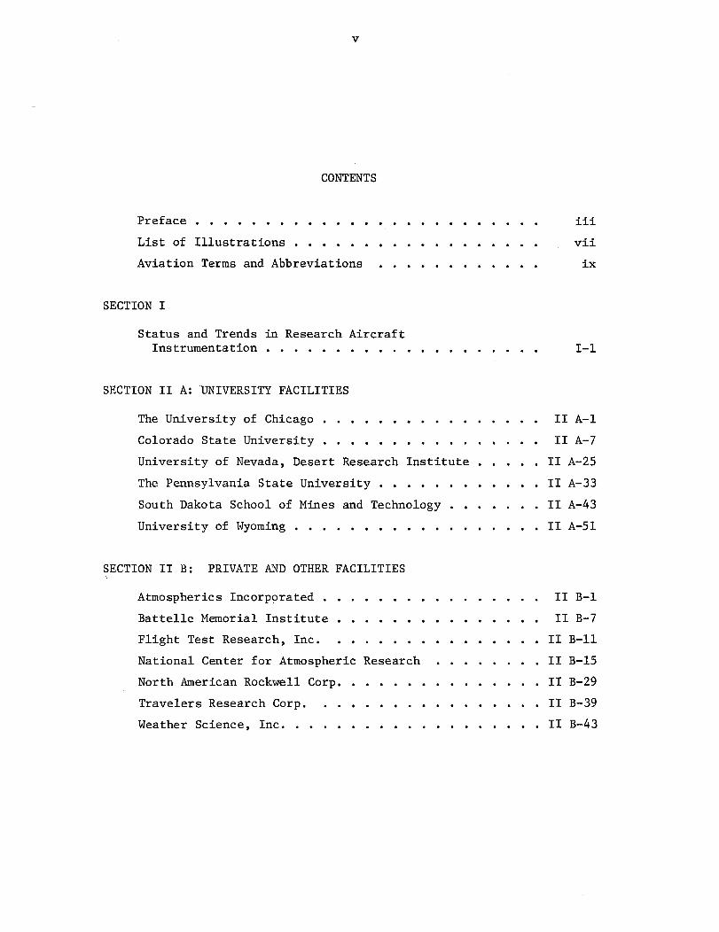
CONTENTS
Preface ......................... iii
List of Illustrations .............. vii
Aviation Terms and Abbreviations .. . ...... . ix
SECTION I
Status and Trends in Research AircraftInstrumentation .................. . I-1
SECTION II A: UNIVERSITY FACILITIES
The University of Chicago ................ II A-1
Colorado State University ................ II A-7
University of Nevada, Desert Research Institute .. . II A-25
The Pennsylvania State University .... ........ II A-33
South Dakota School of Mines and Technology ....... II A-43
University of Wyoming ....... ... ... .. II A-51
SECTION II B: PRIVATE AND OTHER FACILITIES
Atmospherics Incorporated .......... ..... II B-1
Battelle Memorial Institute ........ II B-7
Flight Test Research, Inc ............... II B-ll
National Center for Atmospheric Research ....... II B-15
North American Rockwell Corp ............. II B-29
Travelers Research Corp. ............... II B-39
Weather Science, Inc. .................. II B-43
vi
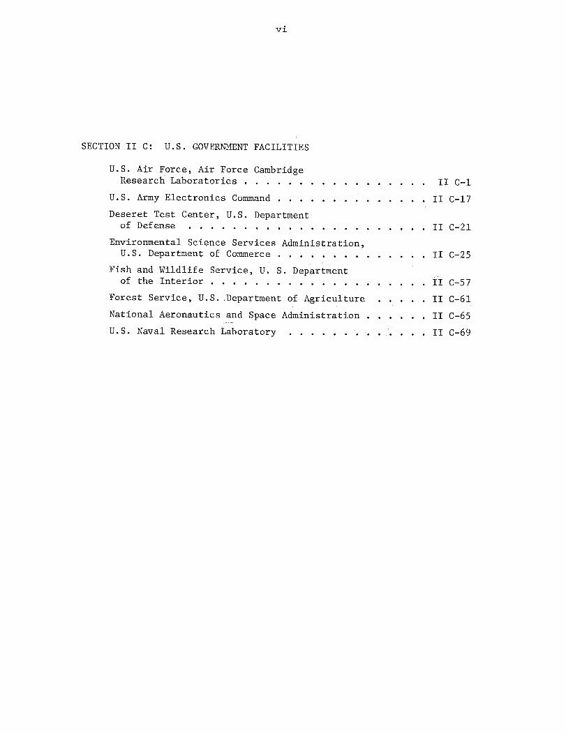
SECTION II C: U.S. GOVERNMENT FACILITIES
U.S. Air Force, Air Force CambridgeResearch Laboratories .... ........... . II C-1
U.S. Army Electronics Command ........ II C-17
Deseret Test Center, U.S. Departmentof Defense ..................... II C-21
Environmental Science Services Administration,U.S. Department of Commerce ............ . II C-25
Fish and Wildlife Service, U. S. Departmentof the Interior .................. . II C-57
Forest Service, U.S. Department of Agriculture . ... II C-61
National Aeronautics and Space Administration ...... II C-65
U.S. Naval Research Laboratory ............ II C-69
vii
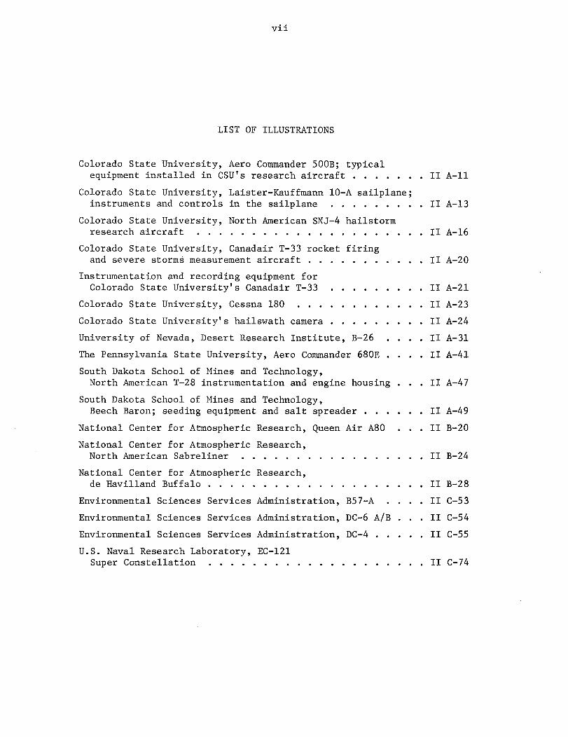
LIST OF ILLUSTRATIONS
Colorado State University, Aero Commander 500B; typicalequipment installed in CSU's research aircraft ...... II A-ll
Colorado State University, Laister-Kauffmann 10-A sailplane;instruments and controls in the sailplane ......... II A-13
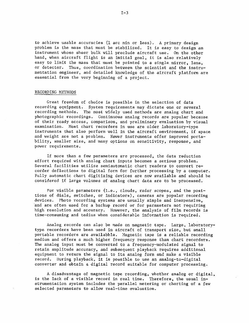
Colorado State University, North American SNJ-4 hailstormresearch aircraft . . . . . . . . . . . . . . . . . . . . . II A-16
Colorado State University, Canadair T-33 rocket firingand severe storms measurement aircraft . . . . . . . . . . . II A-20
Instrumentation and recording equipment forColorado State University's Canadair T-33 ......... II A-21
Colorado State University, Cessna 180 ............ II A-23
Colorado State University's hailswath camera ......... II A-24
University of Nevada, Desert Research Institute, B-26 . . . II A-31
The Pennsylvania State University, Aero Commander 680E . . . . II A-41
South Dakota School of Mines and Technology,North American T-28 instrumentation and engine housing . . . II A-47
South Dakota School of Mines and Technology,Beech Baron; seeding equipment and salt spreader ...... II A-49
National Center for Atmospheric Research, Queen Air A80 . . .II B-20
National Center for Atmospheric Research,North American Sabreliner . . . . . . . . . . . . . . . . II B-24
National Center for Atmospheric Research,de Havilland Buffalo ............... ..... II B-28
Environmental Sciences Services Administration, B57-A . .. II C-53
Environmental Sciences Services Administration, DC-6 A/B . . . II C-54
Environmental Sciences Services Administration, DC-4 . ... II C-55
U.S. Naval Research Laboratory, EC-121Super Constellation .................... II C-74

I
I

ix
AVIATION TERMS AND ABBREVIATIONS
ADF Automatic Direction Finding
DME Distance Measuring Equipment
IAS Indicated Airspeed
LORAN Long-Range Aid to Navigation
PPI Plan-Position Indicator
TACAN Tactical Air Navigation (system); UHF navigationalfacility; direction and distance information
TAS True Airspeed
VGH Velocity, Acceleration, Heading
VOR Very High Frequency Omnirange
VORTAC VOR and TACAN systems combined

I
I

I-1
STATUS AND TRENDS IN RESEARCH AIRCRAFT INSTRUMENTATION
The basic parts of an aircraft research instrumentation system are:sensors, amplifiers and recorders, a power source, and the necessarycontrols and switching. The preparation of an airborne instrumentedplatform is a systems engineering problem; factors of flight profile,sensor type and exposure, aircraft characteristics, recording media,power, installation of equipment, and reduction of the recorded data tousable form must all be considered. In practice, system components areoften selected because they happen to be available; the problem thenbecomes one of integrating the items into a usable system. Any researchinstrumentation system merits a careful analysis, from sensor to dataanalysis procedures, to ensure that data produced will justify the timeand money expended.
SENSORS
In most research systems, more effort is devoted to the developmentof sensors than to any other part of the system because of the unknownfactors that are involved. New, untried sensors and/or techniques mustbe tested to determine their ability for gathering atmospheric data.
If the aircraft platform is available only on a part-time or sharedbasis, the "in and out" requirement and lack of freedom to modify theaircraft structure impose severe constraints in mounting the equipment.Some of the new innovations of sensor installation involve extra remov-able nose sections, doors, and wing tips or tip tanks. An example isthe use of a rack installation to carry an external package. Generally,only sensors would be carried in the external package; the aircraft plat-form would provide the "universal" control, recording, and power facil-ities. It is conceivable that all necessary instrumentation, includingsensor, recorder, and power, could be carried as a self-contained unit.
Many sensors useful in meteorological research are available com-mercially. Requirements of users of meteorological sensors have createda trend toward faster response rates, easier calibration, and digitaloutputs for these instruments. However, the catalog data indicate thata large number of sensors are developed in-house, in contrast to otherportions of research instrumentation systems, which are generallyproven instruments developed for other uses, but which satisfy therequirements of meteorological research projects.
Similarly, some of the sensors used for atmospheric research wereoriginally developed for other purposes and later adapted for atmo-spheric research use. The spectrometer, radiometer, and stable plat-forms are examples. Although use of these sensors will continue, newconcepts are being applied directly to the field of atmospheric research,

1-2
as in the development of laser instrumentation specifically to studyparticulates and clear air turbulence, to determine aircraft altitude,and to determine sea state or snow surface roughness.
Within the near future, major advances in sensing appear imminentin two categories: particulate measurement, and the indirect observa-tion of many parameters by means of their inherent emissions. Particu-late measurement includes the collection or detection of the atmosphere'smost miniscule particles at altitudes from the surface to the greatestheights that aircraft can reach. It includes trapping these particlesin filters, on films, or in containers, and analyzing their compositionat ground laboratories. It also includes sampling their composition andconcentration, in real time, within the aircraft. For real-time sam-pling, sensors will select some physical, chemical, or electrical prop-erty of the particles, such as mass, phosphorescence, or nucleatingpropensity. Ground analysis will also be performed using these tech-niques, together with electron microscope techniques, and activationanalysis.
Emission measurements depend on the fact that all solids, liquids,and gases emit energy on a scale and at wavelengths related to theirthermal condition and thermal properties. Their emissions are greatestat a frequency determined by their temperature, and extend in both direc-tions from the peak in a known manner. Some emissions are essentiallyblackbody (e.g., the ground surface), while others (the gases) have adistinctly banded structure.
Ground or sea water temperature can now be sensed remotely withrelatively simple radiometers. More complicated, but still air transport-able, radiometers and spectrometers can measure cloud top temperatures,and vertical profiles of temperature and water vapor content when cloudsare absent. Semiactive techniques to measure atmospheric dust proper-ties are feasible, using the sun as the source of radiant energy.
Microwave radiometry is being applied to certain large-scaleradiation mapping projects. The techniques in the microwave region arecompletely different from those in other regions of the spectrum. Prob-lems of antenna design, cryogenic cooling, and elaborate signal process-ing take the place of the optical and detector problems associated withvisual and IR wavelength radiometry. At still lower frequencies,electromagnetic radiations by clouds and variations in the electricalproperties of the atmosphere will undoubtedly receive more study and willrequire very sensitive and stable detectors to operate at frequenciesranging from essentially direct current to hundreds of megacycles.
Still another sensor development appears to be necessary: theevolution of better directional stabilization for primary sensors whendirectionally precise observations from aircraft are required. Aircraftobservations of the sun, for instance, will require rough leveling bythe aircraft autopilot or an inertial platform, and fine pointing by aprecise sun-follower. The space age has given us the tools for this job;it is only a matter of adapting these tools to the aircraft environment
I-3
to achieve usable accuracies (1 arc min or less). A primary designproblem is the mass that must be stabilized. It is easy to design aninstrument whose sheer bulk will preclude aircraft use. On the otherhand, when aircraft flight is an initial goal, it is also relativelyeasy to limit the mass that must be pointed to a single mirror, lens,or detector. Thus, coordination between the scientist and the instru-mentation engineer, and detailed knowledge of the aircraft platform areessential from the very beginning of a project.
RECORDING METHODS
Great freedom of choice is possible in the selection of datarecording equipment. System requirements may dictate one or severalrecording methods. The most widely used methods are analog chart andphotographic recordings. Continuous analog records are popular becauseof their ready access, comparison, and preliminary evaluation by visualexamination. Most chart recorders in use are older laboratory-typeinstruments that also perform well in the aircraft environment, if spaceand weight are not a problem. Newer instruments offer improved porta-bility, smaller size, and many options on sensitivity, response, andpower requirements.
If more than a few parameters are processed, the data reductioneffort required with analog chart inputs becomes a serious problem.Several facilities utilize semiautomatic chart readers to convert re-corder deflections to digital form for further processing by a computer.Fully automatic chart digitizing devices are now available and should beconsidered if large volumes of analog chart data are to be processed.
For visible parameters (i.e., clouds, radar scopes, and the posi-tions of dials, switches, or indicators), cameras are popular recordingdevices. Photo recording systems are usually simple and inexpensive,and are often used for a backup record or for parameters not requiringhigh resolution and accuracy. However, the analysis of film records istime-consuming and tedius when considerable information is required.
Analog records can also be made on magnetic tape. Large, laboratory-type recorders have been used in aircraft of transport size, but smallportable recorders are availabble. Magnetic tape is a reliable recordingmedium and offers a much higher frequency response than chart recorders.The analog input must be converted to a frequency-modulated signal toretain amplitude accuracy, and subsequent playback requires additionalequipment to return the signal to its analog form and make a visiblerecord. During playback, it is possible to use an analog-to-digitalconverter and obtain a digital record suitable for computer processing.
A disadvantage of magnetic tape recording, whether analog or digital,is the lack of a visible record in real time. Therefore, the usual in-strumentation system includes the parallel metering or charting of a fewselected parameters to allow real-time evaluation.

I-4
Digital magnetic tape recorders of the computer type are found onlyin larger aircraft systems where a tremendous volume of data makes theadded size and complexity of this type of equipment worthwhile. Digitaldata systems have two definite advantages: first, the sensed data areconverted to a numeric value before recording, and retain their accuracyfrom this point on; second, once recorded, the data can be processedreadily with ground-based computer systems.
A recent innovation in the recorder field, the incremental digitalmagnetic tape recorder, promises to make digital recording more attrac-tive for use in all sizes of airborne, data systems. Unlike computertape transports, which require constant data rate and fixed tape speed,incremental (stepper) recorders record asynchronously (a character at atime) to maintain constant packing density. Steppers advance the tapeonly on receipt of a digital character, and record information receivedat any rate (fixed or variable) from 1 to 300 Hz. There are now manydifferent incremental magnetic recorders on the market, with their advan-tages of digital recording, tape reusability, high information packingdensity, and reliability at high data rates. Many of these recordersare small, compact units suited for aircraft installation or portableuse. Some incremental magnetic recorders can record directly incomputer-compatible format, thereby eliminating secondary conversion.Other less expensive recorders are not directly compatible.
INSTRUMENTATION POWER
Most instrumentation systems require some form of on-board electri-cal power, since the power required by research instruments usually dif-fers from the normal aircraft electrical power system. The standardprivate aircraft power system is 12 V dc; larger twin- and multi-engineaircraft use 28 V dc. Military aircraft have a combination of 28 V dcand 400 Hz ac power, with 400 Hz ac becoming the primary power system.In contrast, most readily available electronic equipment requires stan-dard household 115 V, 60 Hz ac power. For many years, rotary invertershave been used to bridge the gap between the dc power sources and theac power requirements of instruments. More recently, solid state in-verters have been developed which offer many advantages in size, weight,efficiency, and reliability. Conversion from dc to ac is the normal re-quirement for airborne instrumentation, but other conversions are alsooccasionally necessary.
All aircraft are limited in the amount of electrical power they cansupply for instrument use, and instrumentation installations are oftenpower-limited before they are space- or weight-limited. Batteries, ad-ditional aircraft-engine-driven generators, and self-contained auxiliarypower units are some of the means adopted to provide supplementary power.Some of the systems described on the following pages use gas turbine,400 Hz alternator auxiliary power units. One suggested possibility forauxiliary power generation is a fan-driven alternator mounted in theaircraft slipstream.

1-5
AIRCRAFT POSITION AND ATTITUDE
Most research projects need information about the location, atti-tude, and relative motion of the sensor platform. The basic aircraftinstruments provide indications of altitude, airspeed, heading, atti-tude, and time. Common additional requirements are such specializedinputs as angle of attack, acceleration, rate of climb, altitude aboveground level, roll, pitch, and yaw position and/or rates.
The most elementary way to determine the geographic location ofthe platform is by visual reference to the ground. Such visual naviga-tion is quite adequate for much of the low-level and local flying. Ifradio navigation is needed, the VOR/DME system available in the U.S.seems to offer the most utility to the average user. Accuracy obtain-able depends more on local conditions and the condition of receivingand transmitting equipment than on the initial equipment cost. Accu-racy can vary from ± 1 to + 4° in bearing, and from 1 to 2% in distance.Other radio navigation systems such as LORAN and CONSOLAN (long-rangenavigation) and Decca (short-range navigation) could be useful in someapplications.
Doppler and inertial navigation systems are being used by themilitary and by commercial airlines, and are found in a few researchaircraft platforms, but the cost and complexity of available equipmentlimit their use. The typical inertial guidance system provides contin-uous recordable outputs of aircraft pitch, roll, and true heading; air-craft ground track and ground track velocity; north-south and east-westvelocity; aircraft present position in latitude and longitude; andautopilot command outputs.
Ground-based radar is a useful tool for determining aircraft posi-tion and track, although its use restricts the aircraft to a fixedvolume of space which is limited by the range and accuracy capabilitiesof the ground-based radar (or radars). A particular advantage ofground-based radar in cloud physics and rainstorm research is the pos-sibility of a common reference for aircraft and "weather" radar trackinformation, which greatly facilitates data reduction.
Methods to record aircraft position must be selected with the over-all data reduction problem in mind. Manual recording is adequate inmany situations, using paper chart records, a voice record, or magnetictape. The pilot or equipment operator is the link between the aircraftinstruments, visual observation, or navigation equipment readouts, andthe physical record. Greater accuracy and reliability are possible bythe use of normal photographic techniques to obtain a record of aircraftinstrument readings at times of interest. In addition, photographs ofthe atmosphere surrounding the aircraft, or of the surface underneath,are a useful source of data for many experiments. In some experimentsit is necessary to obtain a continuous record of aircraft position and

1-6
altitude to accompany the other sensed data. A few aircraft instrumentshave electrical outputs suitable for recording, but in most cases theinstruments must be modified. If they cannot be modified, it is simplestto provide separate sensors whose outputs can be recorded directly.

THE UNIVERSITY OF CHICAGO PROJECT SUMMARYDepartment of the Geophysical Sciences5723 University AvenueChicago, Illinois 60637 Aircraft and ground-based radar will be used to
determine the general features of precipitatingSource: Roscoe R. Braham, Jr. volumes in the flight area.
Professor of MeteorologyThe aircraft will operate out of Bemidji, Minnesota,
Date: 9/10/70 during the summer months of June, July, and August.During the winter months, flights will be made ona nonscheduled basis for experimental studies insupercooled stratus clouds.
I

ATMOSPHERIC RESEARCH FACILITY ORIGINALLY ISSUED 4/6/65REV I SED 9/10/70
FACILITY: University of Chicago, Cloud Physics Lab ADDRESS: 5730 South Ellis AvenueDepartment of the Geophysical Sciences Chicago, Illinois 60637
PROJECTS AND PRINCIPAL INVESTIGATOR A/C TYPES
1. Precipitation Physics - R. R. Braham, Jr. (NSF) Lockheed Lodestar
2. Cloud Particle Sampling - R. N. Knollenberg (NASA)
GROUND STATION PLAYBACK AND DATA PROCESSING EQUIPMENT
MANUFACTURER ANDTYPE MODEL NU MBER AND INPUT OUTPUT REMARKS
Data reader Benson-Lehner Strip chart Punched cards
SPECIAL FACILITIES

ATMOSPHERIC RESEARCH INSTRUMENTATION AND AIRCRAFT DATA ORIGIALLY ISSUED 4/6/65REVISED 9/10/70
FACILITY: University of Chicago (continued) ADDRESS:NAVIGATION SENSORS AND RECORDERS
REGIST. CRUISING OPER'NL OPERATINGTYPE OREGI. PEEDNG OEING RANGE HOME BASE OPERATING AIRCRAFT OWNER POSITION Dual omni, transponder, DME,AIRCRAFT SEASONLockheed dual UHF, dual ADFLockheedLodestar N9980F ALTITUDE See below
PROJECTS AND PRINCIPAL INVESTIGATORHEADING C-4 compass-gyrosyn to
photobox1. Precipitation Physics: Roscoe R. Braham, Jr. AIRSPEED See below
2. Cloud Particle Sampling: Robert G. Knollenberg
AIRCRAFT Two 250 A, 28 V dc generators;ELECTR IC two 60 Hz, 115 V, 20 A
generators; two 400 Hz, 115 V,POWER 40 A generators
AIRBORNE INSTRUMENTATION
PARAMETER INSTRUMENT TYPE MANUFACTURER AND TIME ON-BOARD POWERPARAMETER INSTRUMENT TYPE M DLNBE R RANGE ERROR REM W^^MODEL NUMBER RNEROR CONSTANT RECORDER REQUIRED
A. Radar echo Radar Bendix RDR-1 Operate on #1 5 A, 28 V dc Horizontal axis scan5 mi
B. Precipitation Foil sampler (drops Developed in-house H20: 200 p; H2 0: ± 50 '; 1/2 in./sec 110 V, 400 Hz, Calibrated in laboratoryparticles indent lead foil) snow pellets pellets and 0.5 A, 28 V dc,
and small ice crystals: 5 A crystals: ± 250 11 3 to 4 mm
C. Cloud droplets Fiber optic particle Developed in-house 5 ,, 1 cm Cloud 10-7 sec #2 8 A, 28 V dcand precipitation measuring systems (2) and at NCAR droplets:particles ± 2.5 p;
precipita-tion:± 100 p
D. Particles Auto-replicator Developed in-house Cloud parti- To ± 2 p 100 V, 60 Hz,16-mm tape cles and smal ideal con- 100 W
ice crystals ditions
ON-BOARD RECORDING AND DISPLAY EQUIPMENT
RECORDER/DISPLAY TYPE MANUFACTURER AND SPEED NUMBER OF INSTRUMENT POWER REMARKMODEL NUMBER CHANNELS INPUTS REQUIREDKS
1. 16-mm camera Multidata III 1 ft/2 sec A 28 V dc Triggered by antenna scan
2. Magnetic tape recorder Ampex 3-3/4 and 4 tracks C 110 V, 60 Hz7-1/2 in./sec
3. Oscillograph Visicorder 1/2 in./sec 24 E - K, L 110 V, 60 Hz,
60 A

ATMOSPHERIC RESEARCH - INSTRUMENTATION AND AIRCRAFT DATA ORIGINALLY ISSU 4/6/65REVISED 9/10/70
FACILITY: University of Chicago (continued) ADDRESS: S A NAVIGATION SENSORS AND RECORDERS
TYPE REGIST. CISI OPER NL RANGE HOME BASE E AIRCRAFT OWNER POSITIONAIRCRAFT NO. SPEED CEILI NO HOMEBASESEASON
Lockheed N9980FLodestar (cont.) ALTITUDE
PROJECTS AND PRINCIPAL INVESTIGATORHEADING
A IRSPEED
AIRCRAFT
ELECTRIC
POWER
AIRBORNE INSTRUMENTATION
MANUFACTURER AND TIME ON-BOARD POWERPARAMETER INSTRUMENT TYPE MODEL NUMBER RANGE ERRORONSANT REORER REMARKS
E. Liquid water Hot wire Johnson-Williams 0 to 6 gm/m3 ~ ± 20% 0.5 sec #3 and 4 110 V, 400 Hz Accurate calibrationcontent Model LWH 0.8 A, 28 V dc not available
@ 15 A
F. Liquid water Paper tape (measure Built in-house Up to 9 gm/m3
± 25% as 1.8 sec delay " 28 V, 45 W Accurate calibrationcontent electric conductivity) above 32°F usually not available
calibrated
G. Temperature, Dry and wet bulb Developed in-house Adjustable; T = ± 0.1°C 0.2 sec DB; " Batteryhumidity (platinum elements) each range = ~ 2 sec WB
8°C
H. Temperature Stagnation Rosemount Engr. Co I
I. Dew point Thermoelectric dew point Bendix Corp. -60 to +400C ± 0.5°C @ 1 sec 110 V 400 Hz,
hygrometer DHAA-IP 300C; 100 W, 28V d
± 20C @ 4 A
-50°C
ON-BOARD RECORDING AND DISPLAY EQUIPMENT
RECORDER/DISPLAY TYPE MANUFACTURER AND SPEED NUMBER INSTRUMENT POWER REMARKMODEL NUMBER CHANNELS INPUTS REQUIRED
4. Magnetic tape recorder In-house (duplicate 7 tracks C-M 28 V dcof NCAR ARIS II) multi-Pemco Recorder channel
5. Photobox (16-mm camera) Developed in-house 1 ft/4 sec L,M, attitudedual VOR,heading
6. Magnetic tape recorder Uher 4000S Voice 1 Voice Batteryactuated

ATMOSPHERIC RESEARCH INSTRUMENTATION AND AIRCRAFT DATA ORIGIALLY ISSUED 4/6/65REVISED 9/10/70
FACILITY: University of Chicago (continued) ADDRESS: NAVIGATION SENSORS AND RECORDE
REGIST. CRUISING OPER'NL OPERATINGTYPE NOR . SPEEGD CEIL;NG N RANGE HOME BASE OPERATNG AIRCRAFT OWNER POSITIONAIRCRAFT N. SED CIN SEASON
Lockheed N9980FLodestar (cont.) , ALTITUDE
PROJECTS AND PRINCIPAL INVESTIGATORHEADING
AIRSPEED
AIRCRAFT
ELECTRIC
POWER
AIRBORNE INSTRUMENTATION
MANUFACTURER AND TIME ON-BOARD POWERPARAMETER INSTRUMENT TYPE MODEL NUMBER RANGE ERRORTAT E ER PEOURE REMARKSCONSTANT RECORDER REQUIRED
J. Pressure Variable reluctance Pace Engr. Co. 0 to 1% full #3, 4, 20 mA, 28 V dcaltimeter transducer P1 and CD-32 35,000 ft scale and 5
K. Airspeed Variable reluctance Pace Engr. Co. 0 to 300 mph 1% full #3, 4, 20 mA, 28 V dctransducer P1 and CD-32 scale and 5
L. Rate of climb Instantaneous vertical 0 to #5speed indicator 3000 ft/min
M. Time Crystal controlled Developed in-house 1 part/l07 #2, 3, 4,oscillator and 5
N. VOR distance Standard A/C DME
0. VOR radial Standard A/C VOR #5
ON-BOARD RECORDING AND DISPLAY EQUIPMENT
RECORDER/DISPLAY TYPE MANUFACTURER AND SPEED NUMBER OF INSTRUMENT POWERMARKMODEL NUMBER CHANNELS INPUTS REQUIRED

l~~~~~~~~~~~~~~~~~~~~~~~~~

COLORADO STATE UNIVERSITY PROJECT SUMMARYAtmospheric Science DepartmentFort Collins, Colorado 80521
1. Design of Descriptive and Theoretical HailstormSource: Peter C. Sinclair Models: P. C. Sinclair. The Mark III, T-33, SNJ-4,
Associate Professor of and LK1OA aircraft are being used to investigate theAtmospheric Science sub-cloud and in-cloud temperature, humidity, and
wind structure. In particular, the investigation isDate: 9/5/70 designed to acquire knowledge of the mass, momentum,
heat, and moisture flux that takes place during thedevelopment, maturity, and dissipation stages oflarge thunderstorms and hailstorms. This informa-tion is being used to formulate descriptive and quan-titative models of hailstorm initiation, growth, anddissipation.
2. Joint Hail Suppression Research -- Airborne HRocket Seeding Project: P. C. Sinclair. The HMark III, T-33 is being used to test the airborneseeding rocket which has been developed by CSU in cooperation with commercial rocket and flight testcompanies. The rocket system is designed to deliverup to 500 gm of nucleating material directly into thesupercooled cloud droplet region of incipient hail-storms. The rocket is fired from a horizontal stand-off position outside of the cloud and travels 3-5 mibefore the nucleating payload is explosivelydetonated. The T-33 provides the necessary reactiontime and mobility required for proper timing of theseeding experiment. In addition, the aircraft isequipped with an instrumentation system for monitor-ing storm behavior before and after the seedingapplication.

3. Atmospheric Limitations to Remote Sensing: 6. The Role of Liquid and Solid ParticulateW. E. Marlatt. NASA's CV990 and CSU's Aero Matter in the Transfer of Radiation throughCommander 500B were used to obtain measure- the Atmosphere: W. E. Marlatt. The CSU Aeroments of aerosols, air temperature, humidity, Commander will be used to investigate the roleincoming solar radiation, albedo and sea of semitransparent and opaque layers on thesurface temperature in support of the BOMEX transfer of visible and infrared radiationproject. This data will be analyzed to through the atmosphere. A field program willevaluate the role of atmospheric aerosols in be conducted to obtain simultaneous profileradiation transfer and to aid in the develop- measurements of aerosols; incoming, reflected,ment of an atmospheric radiation transfer model. and emitted spectral visible and infrared
radiation; air temperature and water vapor con-4. Instrumentation Development for Research tent; and cloud droplet concentration and sizeAircraft: W. E. Marlatt. This project is to distribution. These profile measurements willaid NASA in procuring, assembling and install- be made under different air mass conditions anding a central recording system aboard the NASA different geographical regions.CV990 research aircraft. Control programs ap-plicable to operation of the central recordingsystem for recording and processing of aircraft data will be developed. o
5. Measurement and Interpretation of theSea Surface and Air Temperature Gradients inthe Sub-Cloud Layer in the Barbados IslandRegion in Association with the BOMEX Project:W. E. Marlatt and W. M. Gray. A micro- andmesoscale investigation of the variations ofsea surface and sub-cloud layer horizontal andvertical temperature gradients was conductedusing the CSU Aero Commander during the BOMEXproject. This data will be analyzed in rela-tion to the frictional veering of the wind inthe sub-cloud layer to determine if this is amechanism in the generation of the mesoscale"cloud blob" areas.

ATMOSPHERIC RESEARCH FACILITY ORIGILLY ISSUED 8-26-69REV I SED 9-5-70
FACILITY: Colorado State University ADDRESS: Fort Collins, Colorado 80521Atmospheric Science Department
PROJECTS AND PRINCIPAL INVESTIGATOR A/C TYPES
1. Design of Descriptive and Theoretical Hailstorm Models: P. C. Sinclair Canadair Mark III, T-33
2. Joint Hail Suppression Research -- Airborne Rocket Seeding Project: P. C. Sinclair North American SNJ-4
3. Atmospheric Limitations to Remote Sensing: W. E. Marlatt Cessna 180
4. Instrumentation for Research Aircraft: W. E. Marlatt Laister Kauffmann 1OA
5. Measurement and Interpretation of Sea Surface and Air Temperature Gradients in the Aero Commander 500 B
Sub-Cloud Layer: W. E. Marlatt, W. M. Gray NASA CV990
6. The Role of Liquid and Solid Particulate Matter in the Transfer of Radiationthrough the Atmosphere: W. E. Marlatt
GROUND STATION PLAYBACK AND DATA PROCESSING EQUIPMENT
TYPE MANUFACTURER AND INPUT OUTPUT REMARKS
Digital computer Control Data Corp. Card and tape Card, tape, and University owned6400 printer
Digital computer Digital Equipment Paper tape and Paper tape and Corp. PDP-8S teletype teletype
A/D converter and Redcor Magnetic and paper Tape and teletypecomputer tape
A/D converter Dymec Magnetic tape, Card, paper tape, Department ownedgraphic reader and typewriter
SPECIAL FACILITIES
1. M-33 ground radar
2. FPS-6 and FPS-8 aircraft control radar
3. VHF air/ground communications
4. Private university airport and hangar facilities

ATMOSPHERIC RESEARCH INSTRUMENTATION AND AIRCRAFT DATA ORIGINALLY ISSUED 8-26-69
FACILITY: Colorado State University (continued) ADDRESS: NAVIGATION SENSORS AND RECORDERS
TYPE AlNO |. SPEED IG CEILI NG RANGE HOME BASE OPERATING AIRCRAFT OWNER POSITION 16-mm, downward-looking cameraAIRCRAFT SEASONsma____ and visual navigation
CmAero Christman Field500B 6212X 150 kt 30,000 ft 1000 mi Fort Collins All year Colorado State University ALTITUDE Standard A/C instruments
PROJECTS AND PRINCIPAL INVESTIGATORHEADING Read and recorded by observer
1. Atmospheric Limitations to Remote Sensing: W. E. Marlatt AIRSPEED
2. Sea Surface Temperatures: W. E. Marlatt, W. M. Gray
3. The Role of Particulate Matter on Radiation Transfer; W. E. Marlatt AIRCRAFT 28 V dc,
ELECTRIC 110 V, 60 Hz rotary inverter;
POWER 110 V, 400 Hz rotary inverter
AIRBORNE INSTRUMENTATION
[ PARAMETER | INSTRUMENT TYPE |MANUFACTURER AND TIME ON-BOARD POWER REMARKSINSTRUMENT TYPE MODEL NUMBER RANGE ERROR CONSTANT RECORDER REQUIRED
A. Air temperature Diode bridge Developed in-house -50 to +50°C ± 0.3°C 0.1 sec #1 or 2 110 V, 60 Hzwet bulb 5 sec I
B. IR up flux PRT-5, IT-3 Barnes Engr. Co. -49 to +70°C ± 0.1°C " Internal110 V, 60 Hz H
C. Solar and sky Eppley Sol-a-meter; The Eppley H,
radiation Filter wedge spectro- Laboratory, Inc.,radiometer NASA in-house
D. Reflected Eppley Sol-a-meter The Eppleyradiation Laboratory, Inc.
E. Aerosol counter Light scattering Bausch & Lomb
F. Cloud drops Impactor Developed in-house
G. Refractive index Refractometer ESSA 0 to 999 N ut I sec #1 and 2 28 V dc
H. Condensation Light scattering General ElectricNuclei (continuous_
ON-BOARD RECORDING AND DISPLAY EQUIPMENT
RECORDER/DISPLAY TYPE MANUFACTURER AND SPEED NUMBER OF INSTRUMENT POWER REMARKSMODEL NUMBER CHANNELS INPUTS REQUIRED
1. Digital data acquisition system A-D in-house 20 samples/sec 6 20 110 V, 60 Hz #1 and 2 are not used at the same timeKennedy
2. Analog magnetic tape recorder Pemco 15/16 in./sec 7 7 110 V, 60 Hz
3.16-mm movie camera Bolex Adjustable 2 28 V dc Time-imaged on film with picture
4. Strip chart recorder Moseley 680 Adjustable 1 1 110 V, 60 Hz Used for monitoring
5. Oscilloscope Tektronix 110 V, 60 Hz Used for monitoring
i~ ~ ~ ~ ~ ~ ~ ~ ~~~sdfrmntrn

II A-11
CSU's Aero Commander 500B research aircraft. This aircraft is equippedwith turbocharged engines permitting altitudes in excess of 30,000 ftand has upward and downward viewports for remote sensing devices.
A typical equipment installation inCSU's research aircraft. The planeis equipped with 19 in. equipmentracks, 115 V, 60 Hz; 115 V, 400 Hz;and 28 V dc power. Various methodsfor data recording have also beenutilized (i.e., strip chart, analogmagnetic tape, digital magnetic tape).

ATMOSPHERIC RESEARCH INSTRUMENTATION AND AIRCRAFT DATA ORIGINALLY ISSUED 8-26-69REVI SED 9-5-70
FACILITY: Colorado State University (continued) ADDRESS: NAVIGATION SENSORS AND RECORDERS
TYPE NO.REG S CRUS NG OPER RANGE HOME BASE OPERATNG AIRCRAFT OWNER POSITION Visual and ground radarAIRCRAFT .N SPE C SA
Laister Christman FieldKauffmann N50894 60 mph 45,000 ft -200 mi Fort Collins All year P. C. Sinclair ALTITUDE10A
PROJECTS AND PR INCIPAL INVESTIGATORHEADING Standard A/C instruments
1. Design of Descriptive and Theoretical Hailstorm Models: P. C. Sinclair AIRSPEED
2. Joint Hail Suppression Research - Airborne Rocket Seeding Project: P. C. Sinclair
AIRCRAFT 6 to 24 V dc battery packs
ELECTRIC
POWER
AIRBORNE INSTRUMENTATION
MANUFACTURER AND TIME ON-BOARD POWERPARAMETER INSTRUMENT TYPE MODEL NUMBER RANGE ERROR CONSTANT RECORDER REQUIRED REMARKS
A. Pressure altitude Aircraft altimeter Kollsman 0 to 50,000 ft ± 100 ft 0.5 sec #1Instrument Corp.
B. Airspeed Bendix Aviation 0 to 120 mph ± 1 mph 0.3 secCorp.
C. Total air Resistance wire Developed in-house -30 to +30°C ± 0.3°C 0.5 sec " 24 V dctemperature
D. Rate-of-climb Sailplane variometer Badin Instrument 0 to ± 50 ft/min 0.3 sec "with total energy Co. 2000 ft/min
ON-BOARD RECORDING AND DISPLAY EQUIPMENT
RECORDER/DISPLAY TYPE MANUFACTURER AND SPEED NUMBER OF INSTRUMENT POWER REMARKSRCRE/IPAIYbMODEL NUMBER bLU CHANNELS INPUTS REQUIRED REMARKS
1. 16-mm, time-lapse, movie camera Keystone Model A-9 Framing rate A/D 6 V dc The Airborne Atmospheric Data System0.1 to 10 sec (AADS-IA) is now being converted to(variable by electronic analog sensors and magneticpilot control) tape recording.

Flight and AADS-lA monitoring controls in theCSU's Laister Kauffmann research sailplane, front cockpit of the Laister Kauffmann sailplane.
The AADS-1A instrument package iTn the rearcockpit of the Laister Kauffmann sailplane,

ATMOSPHERIC RESEARCH INSTRUMENTATION AND AIRCRAFT DATA ORIGIu 8-26-69REVISED 9-5-70
FACILITY: Colorado State University (continued) ADDRESS: NAVIGATION SENSORS AND RECORDERS
TYPE REST. C U OEN RANGE HOME BASEOPERATING AIRCRAFT OWNER POSITION VOR and ground radarAIRCRAFT SON
NorthAmer can Fort Collins, VIP AviationSNJ-4 N90650 160 mph 18,000 ft 1000 mi Colorado All year (instrumentation by CSU) ALTITUDE
PROJECTS AND PRINCIPAL INVESTIGATORHEADING Standard A/C instruments (see
also airborne instrumentation)1. Design of Descriptive and Theoretical Hailstorm Models: P. C. Sinclair AIRSPEED
2. Joint Hail Suppression Research - Airborne Rocket Seeding Project: P. C. Sinclair
AIRCRAFT 28 V dc generator; 110 V,ERi 400 Hz, 3-phase, solid state
inverter; and ± 15 V dc supply' .·_______________________________________________________________________ POWER for instrum entation package.
AIRBORNE INSTRUMENTATION
PARAMETER l INSTRUMENT TYPE |MANUFACTURER AND TIME ON-BOARD POWERMODEL NUMBER RANGE ERROR CONSTANT RECORDER REQUIRED REMARKS
A. Pressure altitude Variable reluctance Pace Engr. Co. 0 to 15 psi ± 0.5% full 0 to 103 kHz #1 25 to 30 V dc Note: all errors listed(coarse) CP60 scale frequency j 20 mA refer to system error;
response i.e., sensor, demodulator,
B. Pressure altitude Potentiometer Rahm, PT-71-2 ± 1 psid ± 1% full 0.1 sec 28 V dc signal conditioning, and(fine) scale tape recorder errors.
C. Airspeed Variable reluctance Tavis/Edcliff ± 3 psid 0.5% full 0 to 103 kHz " "4-504 scale frequency
response
D. Total air Platinum wire Rosemount Engr. Co -50 to +100°C ± 1% full 0.1 ,,temperature Model 102E2AL scale to 0.02 sec
E. Angle of attack Vane synchro system Developed in-house ± 15°
± 0.05°
0.1 sec " "and yaw
F. Pitch Vertical gyro Kearfott Co., Inc. ± 15°
0.1°
rms" 26 V, 400 Hz,1-phase
G. Roll " " ± 20° 6 V, 400 Hz,1-phase
ON-BOARD RECORDING AND DISPLAY EQUIPMENT
RECORDER/OISPLAY TYPE MANUFACTURER AND SPEED NUMBER OF INSTRUMENT POWER| ______________ RECORDER/D I SPLAY TYPE __MODEL NUMBER CHANNELS INPUTS REQUIRED REMARKS
1. Analog tape recorder Ampex AR 200 1-7/8 14 A-M 28 V dc Prior to recording, sensor outputs areto 60 in./sec demodulated (if necessary) and passed
through FM amplifiers. All componentsare temperature controlled to laboratorycalibration standards.

ATMOSPHERIC RESEARCH INSTRUMENTATION AND AIRCRAFT DATA oIL ISSUED 8-26-69REV I SED 9-5-70
FACILITY: Colorado State University (continued) ADDRESS: NAVIGATION SENSORS AND RECORDERSNAVIGATION SENSORS AND RECORDERS
REGIST. CRUISING OPER'NL OPERATINGTYPE NO. SPEED CELN RANGE HOME BASE PERATNG AIRCRAFT OWNER POSITION
AIRCRAFT REGIST____O. CUS PEED CEILINGHOE SEASON
North N90650AmericanSNJ-4 (cont.) ALTITUDE
PROJECTS AND PRINCIPAL INVESTIGATOR HEADHEADING
A IRSPEED
AIRCRAFT
ELECTRIC
POWER
AIRBORNE INSTRUMENTATION
MANUFACTURER AND TIME ON.BOARD POWERPARAMETER INSTRUMENT TYPE MODEL NUMBEER RANGROR CONSTANT RECORDER REQUIRED REMARKS
H. Pitch rate Rate gyro Whittaker, R170 ± 10°/sec ± O.l1/sec < 0.1 sec #1 115 V, 400 Hz,3-phase
I. Roll rate " Whittaker, R170 ± 15°/sec " ... "
J. Yaw rate " Honeywell, ± 10°/sec " " ".. JRS101A2
K. Vertical Linear servo Donner Systron Co. ± 5 g + 0.005 g 0.05 sec " 28 V dcacceleration accelerometer Model 4310
L. Lateral " " ± 1 g ± 0.001 g "
acceleration
M. Longitudinal " " " ...acceleration
ON-BOARD RECORDING AND DISPLAY EQUIPMENT
RECORDER/ODISPL AY TYPE MANUFACTURER AND SPEED NUMBER OF INSTRUMENT POWER REMARKSMODEL NUMBER CHANNELS INPUTS REQUIRED
.. .. ..... .
............ ..... ......... ........ �11..... ..... .. ... ....
... ............ ... ............ .............. ............... .......... .... ........................... ............
.... .............. .. ....... ........ ... .................
.......... . ..... .................... ........ .. .......... .................. .... ............ ......... ....... .... ................ ................... ................... ...... ........... ............. ..... ........ ...... ....... ............... ........ ... ............. ........ ... ............... ...... .... ........................................ ... ....... ......... ............................. ........... ............... ... .................. ........... ... ..... ..... ......
MI- ................. ... ........ .... ..... ............. ........ ....... ......... ..... . ............... .. .. ...........- ... ............... .................... ...... ...... ........ ........ ...... ........ .. .......
.............. .. ...-R........................... ........................ ..... E ve........ .......... ............. I.............. ...... ................. . .................... ..................... .......... .... ........ ... . ......... ...... ......... ........ .................. .. ........ .. ............... .................... . ..... .. ........ ........ ........ .......... .......... ...................... ............ .............. .
........... ......................... .............. ......-......... .....
............... ...... ...... ........ X ............ ................... .................... . ...... .. .. ... ...... ............... .. . .... .......... ...... . ....................................... ................... .................................... ............................. ......................................... .................... ................ . ................ .......... .......... ................................. .......... ............. ..... ................... ......................... . ........ ......... ........... .... .. ........ ........ ...... ........ ............... .........
....... ... ......I.... ... ............. .......... .............................. .......:: :::::::::::::: .:::::::::: ... . - :X : :::� ............. . ......... ................... ............ ......................... ............. .......... ....... .................... .............. :X:: .............. ....... .................................... ............... :: :::: : ::::: :::::: :::::::: - 11- 1.11 V ......... ............ ........
... ........ ... ............. .. .... ................... ....... ........- ..... ....................... ;::::::: . ....................... ............ ..... . ... . ...... .. ... ....... .........................
.............. ......... ....... ....... ...... ................ ... ... ......... ..... ....... .. ................. ........... ................ ........ ....... ........ . ........... ............. ............ ...... .. ...... -............. .. ...........:X:_ ....... ............. ...................... .............................
....... ..... . .................. . ....... ..... . .... ......
................ .............. ...... .............................. ..................... ... ................ .. ..... ......... ........ ...
.............. .......... . ..... ...................... .... ... .......... ...........
.......... . ... ................. ...................... ............. ............................ ................... ................
.......... ...... .......... ........ .......................... .. .............. . ............ .. ...... ....... ......
...... ..... .... ......... .....
.......... ...............
....... ...... ......... ...... .... .. .... .
.. ........ ....
..... ....... .. .. .... ............ .......... ..........................
...... ............. ...... ...... .......... .
.................. ...... ...... ................
................................ ........ .................. ...... ..... ... ........ ......
....................... ...........-
.......... .... ..... ...... ...... .. .... ................... .................. ......................
....... ......... .......
..........- ......... ... ..... . .........
......................... ... ......... .
........ ..-
.............. ... ............. .. ..
...... .... ...... ........Fiji...... ............................ ............
. ....... .... ........ .......... ... ....... ...
..... ......... ... .... ... .... . ........
..... ....... ............. X ....... .. .... ..... .......... - ................... .... ......... ..... ... ..... .. .. ................................... . . ............ ................................................. .....-. .. ............ ........................ .............. ..... ......... .. ... .. ...... ....................................... AOOP............ ............................... .......... ......... .....
. .. ........ .......... ...... ..... ....... . . ..... ....... ......... ................I1. .. .. ...... ... ........... I ............... . ...... .... I 1. I ...... . ...........
... .... .1... ..... ... .. ...... .. ......... . ... .................: : : -:-::.: , :: . . ............... .......................................... .... ..... M O W .................................. ........ ... ........................................................... 11.1 11 ............... Q U A =................... 11 ... .... . .. .......................... . .............. ........... . ..... ... .......... ........ ................. ...... . ........ ... ..... ........ 11.1 .. .... ......... ... ...... ...... .. .... . .. ... ....... ..... .. ..... ........................
..... ......... :X.X ........................................... ..... .......... -..... ............ ........... ............... .... ........ ...............
....................................................... ............................... ....... ...... . .. ............ ... .. .............. ....... ....... .... ........OP, ... ...............
............ .......... ............. .... ............. ....... ...... ................ ....... .... ....-..................... .. ... .............. .... ...... .. ....... ....... .................... ........... ... ... ...................... ...... ...... ... ......................................... X ............. ..... ....... I-1- :... -,.I... :.: -::.::.:: "::::.::.:::. .::" .:..: - -::::::;::::;::V V X ;:: _ ... ........................................... .....:::::;::::::: :::X :: :: : ........... -.1 ........... I I........... I..''...'', ........... .............................. .I........................
............
----------------------
I..................... .........:1.1.1 ........... ..................-.111.111- 1 .................
........... . .... ....... .......
....... ......
. ................
I...... .... .............. ...111- .............. 11.11 ........................ ... ... ....... .... ..................
........... X.-................. .......... .. .... .... ................ ;1;;:: :::, :::: . ...... .....
... ......... ...... ......
o i i k i
e eco rIt can, be quickly removed for laboratory check-out, i ion on

ATMOSPHERIC RESEARCH INSTRUMENTATION AND AIRCRAFT DATA ORIGINALLY ISSUED 8-26-69REVISED 9-5-70
FACILITY: Colorado State University (continued) ADDRESS: NAVIGATION SENSORS AND RECORDERSNAVIGATION SENSORS AND RECORDERS
TYPE REGIST. CRUISING OPERN RANGE HOME BASE OPERATING AIRCRAFT OWNER POSITION VOR/DME ground radarAIRCRAFT _'_______ _________NO. SPEEDO CEILING_ ______SEASON
Canadair 0. 7M Long Beach, Flight Test Research, Inc.Mark IIIT- 33 N156X (400 KCAS)45,000 ft 1300 n mii California All year (instrumentation by CSU) ALTITUDE
PROJECTS AND PRINCIPAL INVESTIGATORHEADING Standard A/C instruments
1. Design of Descriptive and Theoretical Hailstorm Models; P. C. Sinclair (see also airborneAIRSPEED instrumentation)
2. Joint Hail Suppression Research -- Airborne Rocket Seeding Project: P. C. Sinclair
AIRCRAFT 24 V dc generator;110 V, 400 Hz, 3-phase solid
ELECTRIC state inverter and ± 15 V dcsupply for instrumentation
POWER package.
AIRBORNE INSTRUMENTATION
MANUFACTURER AND TIME ON-BOARD POWERPARAMETER INSTRUMENT TYPE MODEL NUMBER RANGE ERROR CONSTANT RECORDER REQUIRED REMARKS
A. Pressure altitude Capicitance pressure Rosemount Engr. Co. 0 to 15 psi ± 0.5% full 0.025 sec #1 28 V dc + 10% Note: all errors listed(course) transducer Model 830J9 absolute scale refer to system error;
i.e., they includeB. Pressure altitude Potentiometer pressure Giannini Controls 0 to 0.15 psi ± 1% full 0.1 sec " 28 V dc sensor, demodulator,
(fine) transducer Corp., Model , differential scale signal conditioning, and45176DR-D tape recorder errors.
C. Airspeed Capacitance pressure Rosemount Engr. Co. 0 to 6 psi ± 0.5% full 0.025 sec " 28 V dc ± 10%transducer and Model 831L15 differential scalepitot-static tube Model 850A
D. Total air Platinum wire Rosemount Engr. Co. -75 to +45°C ± 1% full 0.7 to 2 sec " 28 ± 4 V dc,temperature Model 102CS2CA scale 25 mA, 115 V dc
de-icing heater
E. Angle of attack Vane synchro system Developed in-house ± 10°, ± 20
°± 0.05
°0.1 sec " 28 V dc
and yaw
F. Pitch Vertical gyro Kearfott Co., Inc. ± 82°
0.1°
rms 0.1 sec 26 V, 400 Hz,I-phase
ON-BOARD RECORDING AND DISPLAY EQUIPMENT
RECORDER/DISPLAY TYPE MANUFACTURER AND SPEED NUMBER OF INSTRUMENT POWER REMARKSMODEL NUMBER CHANNELS INPUTS REQUIRED
1. Digital, incremental, magnetic tape Incre-Data Inc. 1000 char. /sec 20 A-M 28 V dc Prior to recording, sensor outputs arerecorder Mark II 200 BPI demodulated and passed through eighth-
order Butterworth filters. Allcomponents are temperature controlled tolaboratory calibration standards.
2. Oscilloscope monitor Tektronix, Type 323 22 inputs A-N 28 V dc or Used in pre-f light and in-flight
110 V ac monitoring of system noise levels andvoltage inputs to tape recorder.

ATMOSPHERIC RESEARCH INSTRUMENTATION AND AIRCRAFT DATA REVISED 8-26-6970
FACILITY: Colorado State University (continued) ADDRESS: NAVIGATION SENSORS AND RECORDERS
REGIST. CRUISING OPER'NL RAN G E OPERATINGTYPE NO. SPEED CEILING RANGE HOME BASENG AIRCRAFT OWNER POSITION
PROJECTS AND PRINCIPAL INVESTIGATORHEADING
A IRSPEED
AIRCRAFT
ELECTRIC
POWER
AIRBORNE INSTRUMENTATION
PARAMETER INSTRUMENT TYPE |MANUFACTURER AND RANGE ERROR TIME ON-BOARD POWER REMARKSPARAMETER INSTRUMENT TYPE MODEL NUMBER RANGE ERRORRECORDER REUREED REMARKS
G. Roll Vertical gyro Kearfott Co., Inc. ± 360°
0.1°
rms 0.I sec #1 26 V, 400 Hz,1-phase
H. Heading Directional gyro; Kearfott Co., Inc. ± 90°
< 1°
0.5 sec " 115 V, 400 Hz, Hroll stabilized 3-phase H
I. Pitch rate Rate gyro Smith's Aviation ± 10°/sec ± 0.1°/sec 0.1 sec " 26 V, 400 Hz, 5Division Model 1-phase, 115 V,304RGS/3 400 Hz, 3-phase
J. Yaw rate Rate gyro Smith's Aviation ± 10°/sec ± 0.1°/sec 0.1 sec " 26 V, 400 Hz,Division, Model 1-phase, 115 V,304RCS 400 Hz, 3-phase
K. Vertical Linear servo Donner Systron Co. ± 5 g ± 0.025 g 0.05 sec " ± 15 V dcacceleration accelerometer Model 431F-S-AG ± 2 g ± 0.012 g 0.05 sec 28 V dc
Model 4310-2
L. Lateral Linear servo Donner Systron Co. ± 1 g ± 0.005 g 0.05 sec " 28 V dcacceleration accelerometer Model 4310-1-AG
ON-BOARD RECORDING AND DISPLAY EQUIPMENT
RECORDER/DISPLAY TYPE MANUFACTURER AND SPEED NUMBER OF INSTRUMENT POWER REMARKSMODEL NUMBER CHANNELS INPUTS REQUIRED
ATMOSPHERIC RESEARCH INSTRUMENTATION AND AIRCRAFT DATA ORIGINALLY ISSUED 8-26-69REVI SED 9-5-70
FACILITY: Colorado State University (continued) ADDRESS: NAVIGATION SENSORS AND RECORDERS
TYPE REST. CRUI SPEED EILNG OPERNL RANGE HOME BASE OPERATING AIRCRAFT OWNER POSITION
Canadair N156XMark IIIT-33 (cont.) . ALTITUDE
PROJECTS AND PRINCIPAL INVESTIGATORHEADING
AIRSPEED
AIRCRAFT
ELECTRIC
POWER
AIRBORNE INSTRUMENTATION
PARAMETER INSTRUMENT TYPE MOEL A NUMBER RANGE ERROR TANT RECOROER REQIRES REMARKS
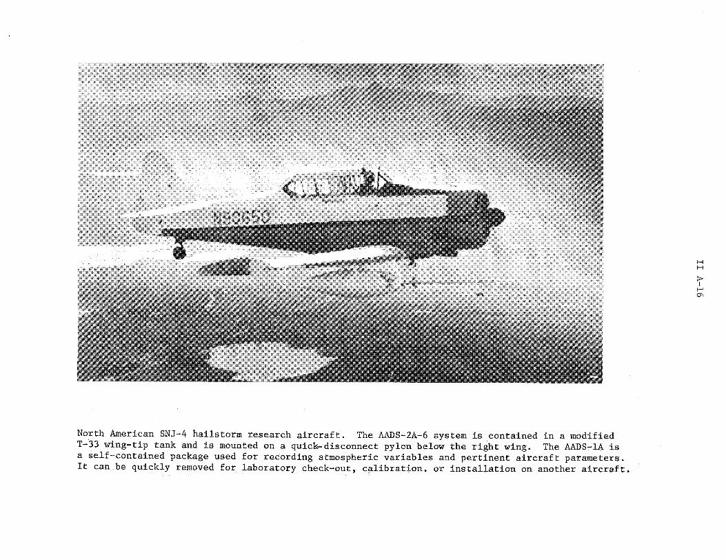
M. Longitudinal Linear servo Donner SystrQn Co. ± 1 g ± 0.005 g 0.05 sec #1 28 V dcaccelerometer accelerometer Model 4310-1
N. Boom vertical and Temperature compensated Micro-measurements ± 1200 ± 1% 0.01 sec #2 28 V dclatitudinal wire strain gage system ED-DY-250BG-350 pstrainbending
0. Cloud seeding CSU rocket delivery A/C carries 2 prototypesystem launchers which hold 7
rockets each.
ON-BOARD RECORDING AND DISPLAY EQUIPMENT
RECORDER/DISPLAY TYPE MANUFACTURER AND SPEED NUMBER OF INSTRUMENT POWER REMARKSMODEL NUMBER CHANNELS INPUTS REQUIRED REMARKS

Rocket firing and severe storms measurement aircraft. The Canadair T-33 jet aircraft performs adual function in acting as the delivery platform for the hailstorm seeding rockets and as the mea-surement platform for the AADS-3B-33 system which is used in the severe storm measurement program.The loaded rocket launchers are located on the pylons below each wing, and the AADS-3B-33 boomsystem positions the gust vane and pressure sensing probes well ahead of the aircraft to minimizeadverse flow characteristics. During the present testing phases of the rocket program, two proto-type launchers are carried with a total capacity of 14 rockets. New launcher designs are availablewith a total capacity of 100 rockets per flight.
.. f i
IN\ ¢;~~~~~~~~~~~~~~~~~~~~~~~~~~~~~~~~~~~~~~~~~~~~~~~~~~~~~~~~~~riiii~ii,,il:::i::·:

- ------------ ~.... .... ... iiiiiiiiiiiiiiiiiiii~-iiiiiii i-l~---~ii~-~~ i~i ii~iiiiaiiiiiiii ~~iiiiiiiii Fe~i
........ .....~~ ~~~ ~~ ~~~~~ ~~~~~ ~~~~~~~~~~~~~~~~~~~~~~~~~~~~~~~~~~~~~~~~~~~~~~~~~~~~~~~~~~~~~~~~~~~~~~~~~~~~~~~~~~~~~~~~~~~~~~~~~~~~~~~~~~~~~~~~~~~~~~~~~~~~~~~~~~~~~~~~~~~~~~-i....... .... ........ .i i~iiii iii ::
.. ....... .. ... ........ i i i i i i iiiiii:iiiiiiiiiiii~~iii,: iiiiii~i~-~iii--iiii~~i
.... .. .... .... ..........~~~~~~~~~~~iiiiii..... ..... ....... ... :i· -,i ii ~ i iii~i~i :: ii
........ ..~~~~~~~~~~~~~~~~~~~~~~~~~~~~~~~~~~~~~~~~~~~~~~~~~~~~~~~~~~~~~~~~~~~~~~~~~~~~~~~~~~~~~~i... .... . ...... . ..... ...... ..~~~~~~~~~~~~~~~~~~~~~~~~~~~~~~~~~~~~~~~~iii~~
.......... '''
. ... ... ... ... ... ..............~ ~ ~ ~ ~ ~l'i'i~~~B~~~iiii ~gippi -ii~i-_iiiiiii--i~~~
.............~ ~ ~ ~ ~ ~ ~ ~~ ~ ~ ~~ ~ ~ ~ ~ ~ ~~~~~~~~~~~~~~~~~~~~~~~~~~:::::::................i~iiiil iiBil i
...........~ ~ iii:;ii l~i BBS~~~...... .......~ ~ ~ ~ ~ ~~~~ ~~~~~~~~~~~~~~~~~~i
.. ... . .. .. .. . . . . .. .. .. . .....
:x. .........~i iiifli:- '·r ~ : ·
........ .... -~~~~~~~~~~~~~~~~~~~~~~~~~~~~~~~~~~~~~~~~~~~~~~~~~~~~~~~~~~~~~~~~~~~~~~~~~a~iiiiii~lllil~iiilii
.......... 3 . ............. ......... .3 B -3 s yte n

ATMOSPHERIC RESEARCH INSTRUMENTATION AND AIRCRAFT DATA ORIGIALLY ID 8-26-69REVISED 9-5-70
FACILITY: Colorado State University (continued) ADDRESS: NAVIGATION SENSORS AND RECORDERS
TYPE . SPEED CEILN RANGE HOME BASE OPERANG AIRCRAFT OWNER POSITION VOR and ground radarAIRCRAFT NO. SING OERNH SEASON
Cessna Christman Field VIP Aviation180 N2707X 130 mph 19,000 ft 500 mi Fort Collins All year (instrumentation by CSU) ALTITUDE
PROJECTS AND PRINCIPAL INVESTIGATORHEADING Standard A/C instruments
1. Design of Descriptive and Theoretical Hailstorm Models: P. C. SinclairAIRSPEED
2. Joint Hail Suppression Research- Airborne Rocket Seeding Project; P. C. Sinclair__
AIRCRAFT 12 V dc generator
ELECTRIC 24 V dc battery pack
POWER
AIRBORNE INSTRUMENTATION
PARAMETER INSTRUMENT TYPE MODEL NU MBER RANGE ERRORT O RDD REMARKFMODEL NUMBER RANGE ERROR CONSTANT RECORDER REQUIRED
Aerial photographic Aerial cameras 4 x 5 in. aircraft Unlimited Framing rate: 24 V dc(IR and visible) (overlapping coverage) camera, Folmer 0.1 to 10 sec
mapping of hailfall Graflex Corp.ground coverage Type K-25B H
ON-BOARD RECORDING AND DISPLAY EQUIPMENT
RECORDER/DISPLAY TYPE MANUFACTURER AND SPEED NUMBER OF INSTRUMENT POWER REMARKSMODEL NUMBER CHANNELS INPUTS REQUIRED

S-R~~~~~~~~~~~~~~~~~~~~~~~~~~~~~~~~~~~~~~~~~~~~~~~~~~~~~~~~~~~~~~~~~~~~~-CS:is Cessna 180 used for hailswath mappings
CUsCesn0t h
............. ...~~~~~~~~~~~~~~~~~~~~~~~~~~~~~~~~~~~~~~~~~~~~~~~~~... ....... ~ ~ ~ ~ ~ ~~ ~ ~ ~~ ~ ~ ~~ ~ ~ ~ ~ ~ ~~ ~ ~~ ~ ~~ ~ ~~ ~ ~~ ~ ~~ ~ ~~ ~ ~~ ~ ~~ ~ ~~ ~~~ ~~~ ~~~ ~~~ ~~~ ~~~ ~~~ ~~~ ~~~ ~~~~~~~~~~~~~~~~~~~~~~~~~~~~~~~~~~~~~~~~~~~~~~~~~~~~~~~~~~~~~~~':':::": '''::'
..........::::
.............. ~ ~ ~ ~ ~ ~ ~ ~ ~ ~ ~ ~ ~ ~ ~ ~ ~ ~ ~ ~ ~ ~~ Wiiii
............... ~ ~ ~ ~ ~ ~ ~ ~ ii::iii liii~lliii-i-iii
~~ii~~~~iiiiir~~~~~~~i;' ......
.... .. ........~~~~~~~~~~~~~~~~~~~~~~~~~~~~~~~~~~~~~~~~~~~~~~~~~~~~~~~~~~i:::i
:::~~~~~~~~~~~~~~~~~~~~~~~~~~~~~~~~~~~~~~~~~~~....
... .. ....... ..... ..... fs ha lsw ~ h app ng

iiiiiii~~~~·i-i~~~i-i- iiii'i'i i~~~~ilii: ........ _i .. .. :i~~~~~~~i~~l:::iiiii~~~i~i~~i~i~~i~i i ~~i :~~..........
7*1ii Uiiiiii~iiiiiiiii~. ::,
................ .... ...
:::: XX; : :::';;:
................ /./
can be photographed using different flight plans.E~ f
...........- ........... Bs~~~1~4~Y~~~···
... ..........~ i~i~i llii lli~:~ii~iiiiii~iiii~iiiiii.. ...........
XXXX':' · ~888 " "~li~~~~~iiQ5 X: ~ iil ::::~
r~~~~j:::;i:::::::::::::~ ~ ~ ~~~~~~~~~~~~~~~~~~.......
Haiswah amea ystm nstlle i .. . .... ..... ............s re se tophtogap
the hailswath as the aircraft flies parallel to the storm movement. Two cameras provide a two-mile~~~~~~~~~~~~~~~~~~~~~~~~~~~~~~~~~~~~~~~~~~~~~~~~~~~~~~~~~~~~~~~~~~~~~...............
lateral coverage of the hailswath from cloud base altitudes. Hailswaths exceeding this two-mile limit~~X. ...........can be photographed using different flight plans.~~~~~~~~~~~~~~~~~~~~~~~~~~~~~~~~~~~~~~~~~~~~~~~~~~~~~~~~~~~~~~~~~~~~~~~~~~~~~~~~~~~~~~~~~~~~~~~~~~~~~~~~~~~~~~~~~~~~~~~~~~~~~~~~~~~~~~~~~~~~~~~~...........

ATMOSPHERIC RESEARCH FACILITY ORIGINALLY ISSUED 9-10-70REVISED
FACILITY: Desert Research Institute ADDRESS: STEAD Facility, Reno, NevadaUniversity of Nevada
PROJECTS AND PRINCIPAL INVESTIGATOR A/C TYPES
1. Sierra Storm Studies and Modification Program (winter): Dr. E. X. Berry, Douglas B-26Flight Facility Director
2. Alberta Hail Studies Program: Dr. Peter W. Summers, Field Coordinator
3. Flagstaff, Arizona Storm Studies: Meteorological Research, Inc.
4. Storms over Cascade Mountains: Dr. P. V. Hobbs, University of Washington
5. Project Skywater Seeding Program: Prof. J. Warburton
6. Project Skywater Evaluation Program: Dr. E. X. Berry
GROUND STATION PLAYBACK AND DATA PROCESSING EQUIPMENT H
MANUFACTURER ANDTYPE MODEL NUMBER INPUT OUTPUT REMARKS
Dataplexer and Sierra Research, Sensor outputs Meter display Portable unit used to display actual flighttelemetry PAM/FM Inc. including computer magnetic tape or data on the ground for real-time evaluationreceiver valves PDP-8 computer
PDP-8 computer Digital Equipment Magnetic tape or Teletype and Additional information can be stored on punchCorporation telemetry output calcomb plotter cards or magnetic tape
X-Y plotters (2) Tektronix, Inc. X-Y positionVariplotter50 x 50 in.
SPECIAL FACILITIES
Two ground-based radars, type M-33, are located in the vicinity of the Desert Research Institute. These radars are used in thewinter field-study programs carried out in the Sierra Nevada Mountains near Reno and Lake Tahoe. The aircraft sensors andseeding mechanisms are in instrumentation pods located beneath each wing. The pods can be replaced by other specialinstrumentation pods if desired by other users of the aircraft. The signal conditioning equipment and recording devices arelocated in the aircraft cabin and can be interfaced to instrumentation pods with little or no modification.*
*Technical Report No. 8, Desert Research Institute, Reno, Nevada, 1969.

ATMOSPHERIC RESEARCH FACILITY ORIGINALLY ISSUED 9-10-70REVISED
FACILITY: Desert Research Institute (continued) ADDRESS:
PROJECTS AND PRINCIPAL INVESTIGATOR A/C TYPES
GROUND STATION PLAYBACK AND DATA PROCESSING EQUIPMENT H
MANUFACTURER AND TYPE MODEL NUMBER INPUT OUTPUT REMARKS
8-channel analog Honeywell 8100 Dataplexer output, Computer-generatedtape aircraft radar and display on a storage
aircraft track scope and teletypeDigital tape Precision sensors. output.
Instrument
SPECIAL FACILITIES
ATMOSPHERIC RESEARCH INSTRUMENTATION AND AIRCRAFT DATA ORIGINALLY ISSUED 9-10-70
FACILITY: Desert Research Institute ADDRESS: NAVIGATION SENSORS AND RECORDERSUniversity of Nevada (continued)
TYPE SNO. S PEED C EILING RANGE HOME BASE OPERATING AIRCRAFT OWNER POSITION VOR/DME X-Y plotterAIRCRAFT SESON'
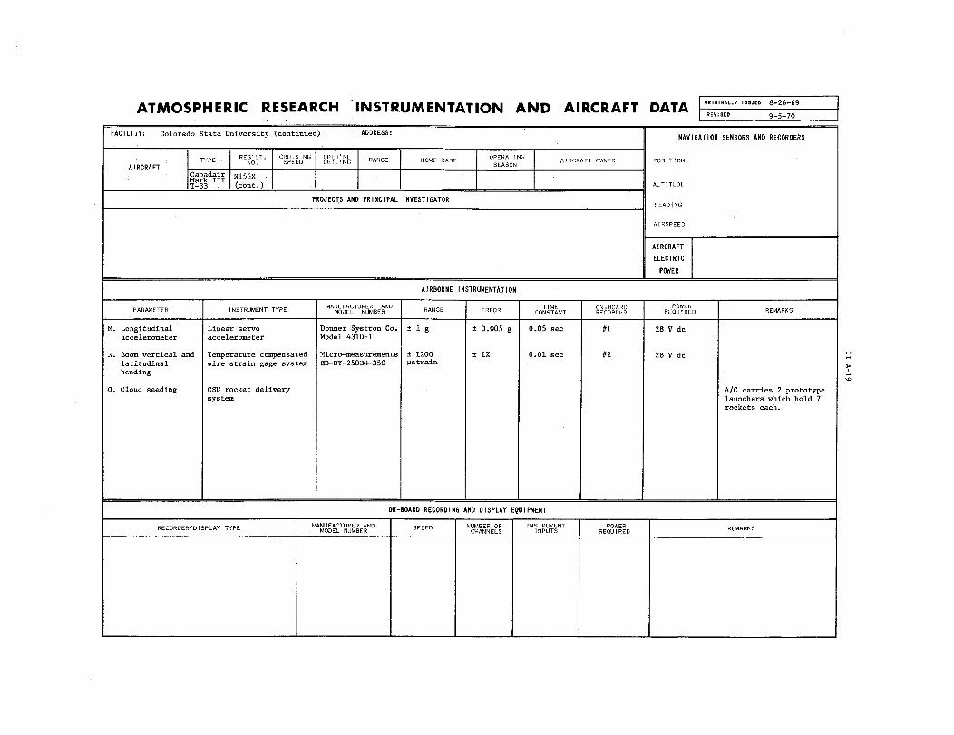
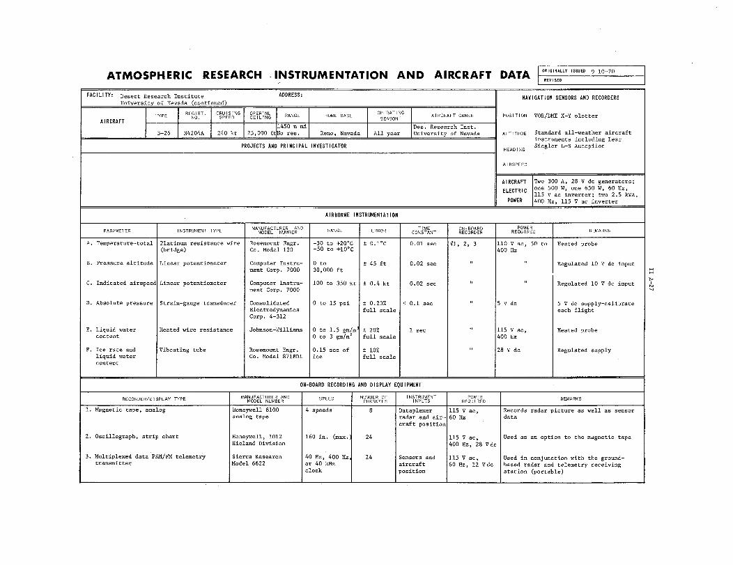
1450 n mi Des. Research Inst.B-26 N4204A 240 kt 25,000 ftNo res. Reno, Nevada All year University of Nevada ALTITUDE Standard all-weather aircraft
instruments including LearPROJECTS AND PRINCIPAL INVESTIGATOR HEADING Siegler L-S Autopilot
AIRSPEED
AIRCRAFT Two 300 A, 28 V dc generators;
ELECTRIC one 500 W, one 650 W, 60 Hz,115 V ac inverter; two 2.5 kVA,
POWER 400 Hz, 115 V ac inverter
AIRBORNE INSTRUMENTATION
PARAMETER INSTRUMENT TYPE | MANUFACTURER AND TIMANGE ON-BOARDER POWER REMARKSMODEL NUMBER RANGE ERROR CONSTANT RECORDER REQUIRED
A. Temperature-total Platinum resistance wire Rosemount Engr. -30 to +20°C ± 0.1°C 0.01 sec #1, 2, 3 110 V ac, 50 to Heated probe(bridge) Co. Model 120 -50 to +10°C 400 Hz
B. Pressure altitude Linear potentiometer Computer Instru- 0 to ± 45 ft 0.02 sec " " Regulated 10 V dc inputment Corp. 7000 30,000 ft
C. Indicated airspeed Linear potentiometer Computer Instru- 100 to 350 kt ± 0.4 kt 0.02 sec " " Regulated 10 V dc input |ment Corp. 7000
D. Absolute pressure Strain-gauge transducer Consolidated 0 to 15 psi ± 0.23% < 0.1 sec " 5 V dc 5 V dc supply-calibrateElectrodynamics full scale each flightCorp. 4-312
E. Liquid water Heated wire resistance Johnson-Williams 0 to 1.5 gm/m3± 20% 1 sec " 115 V ac, Heated probe
content 0 to 3 gm/m3
full scale 400 Hz
F. Ice rate and Vibrating tube Rosemount Engr. 0.15 sec of ± 10% " 28 V dc Regulated supplyliquid water Co. Model 871BDI ice full scalecontent
ON-BOARD RECORDING AND DISPLAY EQUIPMENT
RECORDER/DISPLAY TYPE MANUFACTURER AND SPEED NUMBER OF INSTRUMENT POWER REMARKSMODEL NUMBER CHANNELS INPUTS REQUIRED REMARKS
1. Magnetic tape, analog Honeywell 8100 4 speeds 8 Dataplexer 115 V ac, Records radar picture as well as sensoranalog tape radar and air- 60 Hz data
craft position
2. Oscillograph, strip chart Honeywell, 1012 160 in. (max.) 24 115 V ac, Used as an option to the magnetic tapeHieland Division 400 Hz, 28 V dc
3. Multiplexed data PAM/FM telemetry Sierra Research 40 Hz, 400 Hz, 14 Sensors and 115 V ac, Used in conjunction with the ground-transmitter Model 6622 or 40 kHz aircraft 60 Hz, 12 V dc based radar and telemetry receiving
clock position station (portable)

ATMOSPHERIC RESEARCH INSTRUMENTATION AND AIRCRAFT DATA RIGNL I
FACILITY: Desert Research Institute ADDRESS: NAVIGATION SENSORS AND RECORDERUniversity of Nevada (continued)
ATYPE IA I1 RC8ATIN . CSI NG | RANGE HOME BASE OPERATING AIRCRAFT OWNER POSITIONAIRCRAFT SEASON
N4204AB-26 (cont.) ALTITUDE
PROJECTS AND PRINCIPAL INVESTIGATORHEADING
AIRSPEED
AIRCRAFT
ELECTRIC
POWER
AIRBORNE INSTRUMENTATION
MANUFACTURER AND TIME ON-BOARD POWERPARAMETER INSTRUMENT TYPE MODEL NUMBER RANGE ERROR CONSTANT RECORER REQUIRED REMARKS
G. Rate of climb 0 to 10 m/sec ± 1% > 1 sec #1, 2, 3 12 V dc
H. Time Tuning fork Hornig Variometer 1 sec, 1 min, ± 0.3 sec #1, 2, 3 BatteryAccutron 1 hr
I. Angle of attack Vane torque transmitter Cornell Aeronautic ± 45 min ± 0.1% Analog 115 V dc,Laboratories computer 400 Hz
J. Vertical Force coil Kistter Instruments ± 5 g ± 0.5 0.001 sec Analogaccelerometer Model 305T full scale computer
K. Turbulence Pressure transducer Meteorology 0 to 10 units ± 10% 3 ± 0.5 sec #1, 2, 3 28 V dcResearch, Inc.Model 1120
L. Potential gradient Field mill (rotating) Meteorology 0 to ± 10% #1, 2, 3 115 V ac, 60 Hz Calibration flightResearch, Inc. ± 100 kV/m planned late 1970Model 619
ON-BOARD RECORDING AND DISPLAY EQUIPMENT
RECORDER/DISPLAY TYPE MANUFACTURER AND SPEED NUMBER OF INSTRUMENT POWER REMARKSMODEL NUMBER CHANNELS INPUTS REQUIRED REMARKS
Position plotter X-Y ground reference Hewlett-Packard 7005 Variable X-Y Vortac DME X-Y 115 V ac, Gives continuous plot of aircraft path60 Hz on maps
Position display X-Y radar and A/C track Tektronix 611 CRT Vortac DME X-Y 115 V ac, Superimposes the signal from thedisplay and radar 60 Hz aircraft, now earth-referenced, on a
ground map and the aircraft path trace
Time-lapse camera pictures of storage Bolex H16M 1/min Scope 611 28 V dc, Record of storage scopescope 115 VA, 60 Hz

ATMOSPHERIC RESEARCH INSTRUMENTATION AND AIRCRAFT DATA ISSUED 9-1
FACILITY: Desert Research Institute ADDRESS: NAVIGATION SENSORS AND RECORDERSUniversity of Nevada (continued)
REGIST. CRUISING OPER'NL OPERATINGTYPE A NO. SPEED CEILING RANGE HOME BASE AIRCRAT OWNER POSITIONAIRCRAFT SEASON
N4204AB-26 (cont.) ALTITUDE
PROJECTS AND PRINCIPAL INVESTIGATORHEADING
AIRSPEED
AIRCRAFT
ELECTRIC
POWER
AIRBORNE INSTRUMENTATION
MANUFACTURER AND TIME ON-BOARD POWER
M. Ice nucleus Photoelectric cell Meteorology 0 to 10,000/ Nixie tube 28 V dccounter Research, Inc. display
Model 1511
N. Particle sampler Continuous precoated Developed in-house 0 to 400 u Film record 115 V ac, 60 Hz,Formvar technique 28 V dc
0. X-Band radar Weather radar Bendix RDR-1 0 to 100 mi Ground-
referencedstoragescope
P. Pyrotechnic Rack Developed in-house 24 flaresdispenser
Q. Chaff dispenser Developed in-house
ON-BOARD RECORDING AND DISPLAY EQUIPMENT
RECORDER/DISPLAY TYPE MANUFACTURER AND SPEED NUMBER O INSTRUMENT OR REMARKSMODEL NUMBER CHANNELS INPUTS REQUIRED

ATMOSPHERIC RESEARCH INSTRUMENTATION AND AIRCRAFT DATA IIGLY ISS 9- 1-70
FACILITY: Desert Research Institute ADDRESS: NAVIGATION SENSORS AND RECORDERSUniversity of Nevada (continued)
REGIST. CRUIS!NG OPER'NL RAN G E OPERATINGTYPE REGST. CRUSN PEE CEILN RANGE HOME BASE OPEATAIRCRAFT OWNER POSITION
AIRCRAFT SEASONN4204A
B-26 (cont.) ALTITUDE
PROJECTS AND PRINCIPAL INVESTIGATORHEADING
AIRSPEED
AIRCRAFT
ELECTRIC
POWER
AIRBORNE INSTRUMENTATION
MANUFACTURER AND TIME ON-BOARD POWERPARAMETER INSTRUMENT TYPE MODEL NUMBER RANGE ERROR CONTANT REORR EIRD REMARKS
R. X-Y plotter DME Vortac-Sin-Cos Developed in-house ± 5% @ 80 5 sec Hewlett- 115 V ac, 60 Hzcomputer mi Packard
X-Y plotterand magnetic tape
w
COMPUTED DATA
A. True airspeed Analog computer built " 100 to 350 kt < 1% < 1 sec #1, 2, 3 115 V ac, 60 Hz, Installed and calibratedin-house or 115 V ac,
400 HzB. True static " " -80 to + 20
0C " " "
temperature
C. Mach number " " 0 to 0.5 " " " 115 V ac, 60 H, Installed and calibratedor 115 V ac,400 Hz
ON-BOARD RECORDING AND DISPLAY EQUIPMENT
RECORDER/DISPLAY TYPE MANUFACTURER AND SPEED NUMBER OF INSTRUMENT POWER REMARKSMODEL NUMBER CHANNELS INPUTS REQUIRED

Desert Research Institute's B-26 research aircraft.

I
I

THE PENNSYLVANIA STATE UNIVERSITY PROJECT SUMMARYCollege of Earth and Mineral SciencesDepartment of Meteorology503 Deike Building 1. An Investigation of the Dynamics and Micro-University Park, Pennsylvania 16802 physics of Clouds: Aircraft and surface networks
are employed to obtain coordinated observations ofSource: Charles L. Hosler, Dean the microphysics, dynamics, and environmental prop-
erties of shower situations which are compared toDate: 8/27/70 numerical models of precipitation processes. Defin-
itive experiments are being performed, both in thefield and laboratory, to aid in the assessment ofthe consequences of artificial modification ofclouds. Data derived from these programs are ulti-mately used to relate changes in the formation ofprecipitation as predicted by numerical calculations.
2. Atmospheric Turbulence: The properties and Hstructure of atmospheric turbulence are being studied with data obtained from measurement programsutilizing tower and aircraft instrumentation.
INSTRUMENTATION SUMMARY
The Aero Commander 680E is equipped with a completecloud physics instrumentation package. The instru-ment sensors primarily associated with in-cloudmeasurements are mounted in a removable pod underthe right wing. The sensors for standard meteoro-logical measurements are fuselage-mounted toincrease the operational flexibility of the aircraft.An identical pod under the left wing may be set upto carry two types of pyrotechnic seeding devices

or a continuous gelatin cloud-particle sampler.The removable sampling tube for the high-speedhydrometeor sampler projects through the roofof the fuselage. The camera is mounted at therear of the cabin. Cabinets containing the dataacquisition system and sensor signal condition-ing electronics are mounted to the floor behindthe copilot position. The data system isequipped with a crystal-controlled time base,programable gain and format switching, plusvarious event marks and manual data entries.Systems programming has been developed for thePSU IBM 360/67 computer to automatically reduceand output the data in various user-selectableformats.
Lo

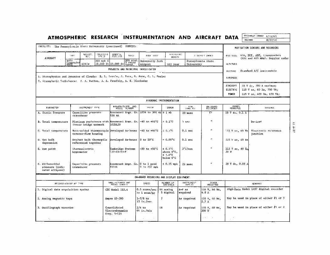
ATMOSPHERIC RESEARCH FACILITY ORIGINALLY ISSUED 4/12/65REVISED 8/27/70
FACILITY: The Pennsylvania State University ADDRESS: 503 Deike Building
Department of Meteorology University Park, Pennsylvania 16802
PROJECTS AND PRINCIPAL INVESTIGATOR A/C TYPES
1. Microphysics and Dynamics of Clouds: R.L. Lavoie, J. Pena, R. Pena, C.L. Hosler (NSF) Aero Commander 680E
2. Atmospheric Turbulence: J.A. Dutton, H.A. Panofsky, A.K. Blackadar (USAF,NSF)
GROUND STATION PLAYBACK AND DATA PROCESSING EQUIPMENT
TYPE MANUFACTURER AND INPUT OUTPUT REMARKS
Digital computer IBM 360/67 Cards, magnetic Same as imput plus Remote job entry (RJE) available. MVT operatin
and punched tape, high-speed printer, system under HASP expected to be operational
disc pack Calcomp 564 plotter early in 1970
and IBM 2250 CRTdisplay
Digital computer IBM 1401 Cards, magnetic Cards, magnetictape tape, printer
Hybrid computer EAI 680 plus DEC Analog tape, Same as input plus Time sharing Fortran available on PDP 10/40
PDP 10/40 w/EAI punched tape, key- X-Y plotter and CRT
693 interface board, dectape display
SPECIAL FACILITIES
Three M-33 radar systems with 403 MHz and ATC transponder capability.
APQ-13 radar system.

ATMOSPHERIC RESEARCH FACILITY ORIGINALLY ISSUD 4/12/65REVISED 8/27/70
FACILITY: The Pennsylvania State University (continued) ADDRESS:
PROJECTS AND PRINCIPAL INVESTIGATOR A/C TYPES
GROUND STATION PLAYBACK AND DATA PROCESSING EQUIPMENT
TYPE MANUFACTURER AND INPUT OUTPUT REMARKS
Graphic digitizer Calma 302 Analog graphs, 7-track BCD Serial-to-parallel conversion of multi-channelstrip charts magnetic tape of strip charts software available
readings takenevery 0.01 in.
Analog digital Universal ± 1.41 V dc analog Three digits + sign Designed for use with Ampex SP-300 recorder;computer Comptronics, Inc. single channel on punched paper or maximum scan rate using magnetic tape output:
7-track magnetic 70 scans/sec.tape
SPECIAL FACILITIES
• f i '~~~~~~
ATMOSPHERIC RESEARCH INSTRUMENTATION AND AIRCRAFT DATA JINALLY ISSUED 4/12/65REVISED 8/27/70
FACILITY: The Pennsylvania State University Ccontinued) ADDRESS: NAVIGATION SENSORS AND RECORDERS
REGIST. CRUISING OPER'NL OPERATINGTYPE NO. SPEED CEILING RANGE HOME BASE AIRCRAFT OWNER POSITION VOR, DME, ADF, transponders
AIRCRAFT SEASON(ATC and 403 MHz). Doppler radarAero 200 mph @ 900 stat. University Park Pennsylvania StateCommande @ rated680E 6297B 10,000 ft 25,000 ft speed Airport All year University ALTITUDE
PROJECTS AND PRINCIPAL INVESTIGATORHEADING Standard A/C instruments
1. Microphysics and Dynamics of Clouds: R. L. Lavoie, J. Pena, R. Pena, C. L. HoslerAIRSPEED
2. Atmospheric Turbulence: J..A. Dutton, H. A. Panofsky, A. K. Blackadar
AIRCRAFT 28 V dc, 200 A maximum;
ELECTRIC 115 V ac, 60 Hz, 750 VA;
POWER 115 V ac, 400 Hz, 670 VA;
AIRBORNE INSTRUMENTATION
MANUFACTURER AND TIME ON-BOARD POWERPARAMETER INSTRUMENT TYPE MODEL NUMBER RANGE ERROR CO NT REQUIRED REMARKS
A. Static Pressure Capacitive pressure Rosemount Engr. Co. 1034 to 300 mb ± 1 mb 20 msec #1 28 V dc, 0.1 Atransducer 830 BA
B. Total temperature Platinum resistance with Rosemount Engr. Co. -40 to +40°C ± 0.1°C 5 sec " De-icedlinear bridge network 102DL2U
C. Total temperature Butt-welded thermocouple Developed in-house -40 to +40°C ± 0.5°C 0.1 sec " 115 V ac, 60 Hz Electronic referencereverse-flow housing junction
D. Wet bulb Dry/wet bulb thermopile Developed in-house 0 to 20°C = 0.05°C 0.1 sec " 115 V ac, 60 Hzdepression referenced together
E. Dew point Thermoelectric Cambridge Systems -50 to +50°C ± 0.5°C 3°C/sec " 115 V ac, 60 Hz,hygrometer 137-C3-S3-P above 0°C, 20 W
± 1.0Cbelow 0"C
F. Differential Capacitive pressure Rosemount Engr. Co. 0 to 1 psid ± 0.35 mph 25 msec " 28 V dc, 0.05 Apressure (indi- transducer 831A4 0 to 237 mphcated airspeed)
ON-BOARD RECORDING AND DISPLAY EQUIPMENT
MANUFACTURER AND SPEED NUMBER OF INSTRUMENT POWERRECORDER/DISPLAY TYPE MODEL NUMBER CHANNELS INPUTS REQUIRED REMARKS
1. Digital data acquisition system CEC Model 123.4 0.5 scans/sec 40 analog A-P as 110 V, 60 Hz, Digi-Data Model 1457 digital recorderto 1 scan/hr 5 digital required 4.8 A
2. Analog magnetic tape Ampex SP-300 1-7/8 to 7 As required 110 V, 60 Hz, May be used in place of either #1 or 315 in./sec 2.7 A
3. Oscillograph recorder Consolidated 1/4 to 18 As required 110 V, 60 Hz, May be used in place of either #1 or 2Electrodynamics 64 in./min 350 WCorp. 5-124

ATMOSPHERIC RESEARCH INSTRUMENTATION AND AIRCRAFT DATA ORIGINALLY ISSUED 4/12/65LR£VlS£E 8/27/70
FACILITY: The Pennsylvania State University (continued) ADDRESS: NAVIGATION SENSORS AND RECORDERS
REGIST. CRUISING OPER'NL OPERATINGRRAFTY NO. PE ED CEItNG RANGE HOME BASE AAIRCRAFT OWNER POSITIONAIRCRAFT N. SED CIN SEASON
Aero 6297BCommander680E (cont.) ALTITUDE
PROJECTS AND PRINC-IPAL INVEST IGATORHEAD ING
A IRSPEED
AIRCRAFT
ELECTRIC
POWER
AIRBORNE INSTRUMENTATION
MANUFACTURER AND TIME ON-BOARD POWERPARAMETER INSTRUMENT TYPE MODEL NUMBER RANGE ERROR CONSTANT RECORDER REQUIRED REMARKS
G. A/C heading Gyro compass Sperry Gyroscope -0 to 3600 + 2°
-1 sec # 1 + 15 V dc, Compass synchro outputCo. C-4 100 mA converted to 1 V dc
sin-cos 0
H. VOR distance DME receiver Collins 860-1 " 115 V, 400 Hz,250 VA
I. VOR heading VOR receiver Collins and ARC O to 360°
+ 3°
" Converted to digitalinput with shaft encoder
J. Ground speed/drift Doppler navigation radar Singer-General O to 200 kt 0.75 kt 1 sec " 115 V, 400 Hz,angle Precision, t 40
°0.170 425 VA
GPK 1000 (averagedover 10 nmi)
K. Liquid water Hot wire Johnson-Williams, 0 to 6 gm/m3
0.65 sec 110 V, 400 Hz,content Model LWH 80 W, 28 V dc,
15 A
ON-BOARD RECORDING AND DISPLAY EQUIPMENT
R.ECORDE R/ D I SPLAY TYPE - MANUFACTURER AND SPEED NUMBER OF INSTRUMENT POWER REMARKSRECORDER/DISPLAY TYPE MODEL NUMBER CHANNELS INPUTS REQUIRED
4. Voice recorder IBM 224 1 Battery
5. 35-mm camera Praktina Adjustable Downward-looking
6. 16-mm camera Bell & Howell Co. Time-lapse

ATMOSPHERIC RESEARCH INSTRUMENTATION AND AIRCRAFT DATA ORIGINALLY ISSUED 4/12/65REVISED 8/27/70
FACILITY: The Pennsylvania State University (continued) ADDRESS: NAVIGATION SENSORS AND RECORDERS
REGIST. CRUISING OPER'NL OPERATINGTYPE CILI RANGE HOME BASE O PERATN AIRCRAFT OWNER POSITION
RESIST~~~~~~~NO. CRUSPEEDI CEILINGL RNE HM AH SEAISON
~~~~~~~~~~~~~~~~~~~~~~~~~~~~|AIRCRAFT
Aero 6297BCommander680E (cont.) ALTITUDE
PROJECTS AND PRINCIPAL INVESTIGATOR
AIRSPEED
AIRCRAFT
ELECTRIC
POWER
AIRBORNE INSTRUMENTATION
MANUFACTURER AND TIME ON-BOARD POWERPARAMETER INSTRUMENT TYPE MOEL NUER RANGE ERROR CONSTANT RECORDER REQUIRED REMARKS
L. Surface or cloud IR radiometer (8 to 14 1 Barnes Engr. Co. -40 to 65°C 2°(above O0C) 0.05 sec or #1 110 V ac, 60 Hz, Downward-looking
temperature band) 3°
field IT-3 4°
(elow O°C) 0.5 sec 25 W
M. Horizontal and Field mill Meteorology 0 to 100 kV/m " 110 Y ac, 60 Hz, H
vertical electric Research, Inc. 10 W field components
N. Hydrometeor charge Coaxial Faraday cage Meteorology 0 to 110 V ac, 60 Hz,Research, Inc. 1000 pCb/V 20 W
O. S0 2 concentration Sign-X Labs 603D " 115 V ac, 60 Hz,0.5 A
P. Turbulence Ap transducer, with Giannini Controls ± 120 cm/sec ± 15 cm/sec 0.053 to #1 or 2 28 V dc, 20 W, On loan from Universityaccelerometer and gyro Corp., gust probe 26.4 Hz 110 V, 400 Hz, of Wisconsin
30 W
ON-BOARD RECORDING AND DISPLAY EQUIPMENT
RECORDER/ DSPLAY TE MANUFACTURER AND SPEED NUMBER OF INSTRUMENT POWER REMARKSRECORDER/DISPLAY TYPE MODEL NUMBER CHANNELS INPUTS REQUIRED

ATMOSPHERIC RESEARCH -INSTRUMENTATION AND AIRCRAFT DATA ORIGINALLY ISSUED 4/12/65REVISED 8/27/70
FACILITY: The Pennsylvania State University (continued) ADDRESS: NAVIGATION SENSORS AND RECORDERS.
REGIST. CRUISING OPER'NL OPERATINGONAIRCRAFT TYPE RANGE HOME BASE AIRCRAFT OWNER POSITION
Aero 6297BCommande (cont.) ALTITUDE680 E · ^ ') ALTITUDE
PROJECTS AND PRINCIPAL INVESTIGATORHEADING
AIRSPEED
AIRCRAFT
ELECTRIC
POWER
AIRBORNE INSTRUMENTATION
MANUFACTURER AND TIME ON-BOARD POWERPARAMETER INSTRUMENT TYPE MOEL NUMER RANGE ERROR CONSTANT RECORER REQUIRED REMARKS
Q. Hydrometeor High-speed, rotating- Developed in-house 300 ,u (min) < ± 10%, 0.8 ,sec Self- 28 V dc, 5 A Uses Fairchild HS-401spectrum prism motion picture D > 0.7 mm (strobe recording, (max.), 115 V ac, camera
camera, "shadowgraph" < ± 5%, duration) event mark 50 to 400 Hz,principle D > 1.2 mm on #1 15 W
R. Cloud particle Gelatin coated, Developed in-house 0 to 1 gm/m3
Self- 100 V ac spectrum continuous 16-mm film cloud liquid recording, o
sampler water content event markon # 1
S. Aerosol Cascade impactor Unico Model 1/2 to 20 U Determined Microscope Noneconcentration 1600-10 diam in four by desired slide
stages spectralrange
ON-BOARD RECORDING AND DISPLAY EQUIPMENT
|RECORDER/DISPLAY TYPE | MANUFACTURER AND SPEED NUMBER OF INSTRUMENT POWER REMARKSMODEL NUMBER CHANNELS INPUTS REQUIRED

.. ::-::_:--__:-::---i~~~~~~~~~~~~~~~~~~~~~~~~~~~~~~~~~~~~~~~~~~~~~~~~~~~~~~~~~~~~i~~~~~~i~~~~~~iii__iiiiiii~~~~~~~~~~~~~~~~~~~~~~~~~~~~~~~~~~iii :--iii-ii_-:-:__-:-:___:_-_:-:- ....._~ ~ ~ ~ ~~~~~~~~~~~~~~~~~~~~~~~~~~~~~~~~~~~~~~~~~~~~~~~~~~~~~~~~~~~~~~~~~~~~~~~~~~~~~~~~~~~~~~iiiii~iii~iiiiii
H
H
:::::::::::::::::::::::::::::::::::::::: -iii~~~~~~~~~~~~~~~~~~~~~~~~~~~~~~~~~~~~~i~~i-i~~~~jii-....~iiiiiiii,
~~ ~ ~The Pennsylvania State University, Department of Meteorology, Aero Commander 68GB.
::::i::j:::.:::.:::::-:-i:.:::j:::::-::: ::: : ::::::::::::: :: : : :::::::::: ::: :::::::::::: ::::::: ::: I::_:::_:::-::-:_::::::i::::-:-: :::-:_:_:_::-:-:-i-i:_:_::i~~~~~~~~~~~~~~~~~~~~~~~~~~~~~~~~~~~~~~~~~~~~~~~~~~~~~~~~~~~~i_:_-_-:-ii_ ..... -i--i _:.-_--:-:-li::----_:-:_::I_:---: _~~~~~~~~~~~~~~~~~ill


SOUTH DAKOTA SCHOOL OF MINES AND TECHNOLOGY INSTRUMENTATION SUMMARYInstitute of Atmospheric SciencesRapid City, South Dakota
The instrumentation on the North American T-28 is
Source: Richard A. Schleusener, Director used in studies of the physical properties ofcumulonimbus clouds and of the mean structure of
Date: 9/10/70 clouds, including dimensions, updrafts, liquid watercontent, and ice particle concentration.
A Beech Baron is used to seed cumulus clouds withsilver iodide and salt as well as to determine theenvironmental conditions in the vicinity of theseeding aircraft. Three methods are used fordispersing seeding materials: acetone generators,pyrotechnic flares, and a salt hopper with spreader.
HJ

ATMOSPHERIC RESEARCH FACILITY ORIGINALLY ISSUED4/12/65REV ISED 9/10/70
FACILITY: South Dakota School of Mines and Technology ADDRESS: Rapid City, South DakotaInstitute of Atmospheric Sciences
PROJECTS AND PRINCIPAL INVESTIGATOR A/C TYPES
1. Cloud Climatology: R. A. Schleusener, J. H. Hirsch North American T-282. Microphysics of Hailstorms (including cloud seeding studies): R. A. Schleusener Beech A-55 (Baron)
GROUND STATION PLAYBACK AND DATA PROCESSING EQUIPMENT H
MA NUFACTURER ANDTYPE MODEL NU MBER INPUT OUTPUT REMARKS | .
Computer IBM 1130 Cards, paper tape Cards/printout 16,000, 3 disk drives
Computer PDP-8 Analog, paper tape Paper tape/printout 8,000, 3 magnetic tape, CRT display
Digitizer Auto-Trol 3600 Strip charts Cards X-Y readout
SPECIAL FACILITIES
1. Two dual-wavelength Nike-Ajax radar systems; acquires weather data and tracks aircraft.Five PPI displays; one for 3-cm, time-lapse photography, four for visual study. Four 3-cm radars; two aircraft trackers,one multiple-range gate, one for PPI photography.
2. Two IFF (L-band) radars for aircraft identification.3. One FPS-6 height finder 10-cm radar with remote display for photography.

ATMOSPHERIC RESEARCH INSTRUMENTATION AND AIRCRAFT DATA ORIGIA 9/10/70REVISED
FACILITY: South Dakota School of Mines and Technology ADDRESS: NAVIGATION SENSORS AND RECORDERS(c ^^i^ F ^"' ^ ^" "' ^^ ^ ^ ^ NAVIGATION SENSORS AND RECORDERS(continued)
TYPE REST. CUPESNG OCEIRN RANGE HOME BASE OPERATN AIRCRAFT OWNER POSITION VOR, DME, L-band andAIRCRAFT NO. SPEE CEILIN SEASON X-band transponders
ortAmericanT-28 510 MH 240 kt 25,000 ft 850n mi Rapid City, S.D. April-Sept. SDSM&T ALTITUDE
PROJECTS AND PRINCIPAL INVESTIGATOR HEADING See Instrumentation._______________________________________________HEADING See Instrumentation
Microphysics of Hailstorms: R. A. Schleusener AIRSPEED
AIRCRAFT 28 V, 200 A generator,
ELECTRIC 110 V, 400 Hz, 500 W,110 V, 60 Hz, 500 W,
POWER ± 15 V dc
AIRBORNE INSTRUMENTATION
MANUFACTURER AND TIME ON-BOARD POWERPARAMETER INSTRUMENT TYPE MODEL NUMBER RANGE ERROR CONSTANT RECORDER REQUIRED REMARKS
A. Pressure Pressure transducer Ball EX-210-B -200 to ± 1% #1 and 2 28 V dcaltitude 30,000 ft
B. Pressure Pressure transducer CIC 7000 0 to 30,000 ft ± 100 ft " " MetroData TVH 26altitude
C. Airspeed Transducer CIC 7100 0 to 350 kt ± 2 kt " " "
D. Temperature Thermistor TS 22 -30 to +30°C ± 0.2°C "
E. Rate of climb Variometer Ball 101A -3000 to +6000 ± 2% 0.5 sec
F. Temperature Platinum resistance Rosemount 102 -40 to +80°C ± 0.5°C 0.025 sec
G. Liquid water Hot wire Johnson-Williams 0 to 6 gm/m3
20% 0.5 sec " 110 V, 400 Hz 2 scalescontent
H. Position VOR, DME Aircraft Nav-Aids 0 to 100 n mi " 28 V dc MetroData VT21
ON-BOARD RECORDING AND DISPLAY EQUIPMENT
RECORDER/DISPLAY TYPE MANUFACTURER AND SPEED NUMBER OF INSTRUMENT POWER REMARKSMODEL NUMBER CHANNELS INPUTS REQUIRED
1. Magnetic tape - digital MetroData DL 620 48 channels/ 20 All 110 V, 60 Hzsec
2. Oscillograph Consolidated Electro4 in./min 18 All 110 V, 60 Hz To be discontinued FY 1971dynamics Corp. 5-124
3. Audio tape Aiwa 1-7/8 in./sec 2 Intercom, hail 9 V dcimpact

ATMOSPHERIC RESEARCH INSTRUMENTATION AND AIRCRAFT DATA REVISED' REVISED
FACILITY: South Dakota School of Mines and Technology ADDRESS:( F continued)^ ' NAVIGATION SENSORS AND RECORDERS
TYPE OREGI. RSPEED COPERNL RANGE HOME BASE AIRCRAFT OWNER POSITIONAIRCRAFT NO. SPEED CEILING SEASON
Northmican 510 MH ALTITUDE
(cont.) PROJECTS AND PRINCIPAL INVESTIGATORHEADING
AIRSPEED
AIRCRAFT
ELECTRIC
POWER
AIRBORNE INSTRUMENTATION
MANUFACTURER AND TIME ON.BOARD POWERPARAMETER INSTRUMENT TYPE MODEL NUMBER RANGE ERROR CONSTANT RCORDER REQUIRED REMARKS
I. Raindrop Piezoelectric force MetroData RR40 0.35 to 0.42 sec #1 28 V dc 9 raindrop classesspectrometer > 4 mm
J. Time Clock Bulova Accutron 24 hr #1 28 V dc
K. Event-condition Pulse MetroData 0 to 9 events #1 and 2 15 V dc
L. Spar strain Strain gage BLH model SR-4 40,000 to ± 1% #2 5 V dc 8 in place on spar60,000 psi
M. Vertical Accelerometer Statham A-45 ± 15 g #1 and 2 12 V dcacceleration
ON-BOARD RECORDING AND DISPLAY EQUIPMENT
RECORDER/DISPLAY TYPE MANUFACTURER AND SPEED NUMBER OF INSTRUMENT POWER REMARKSMODEL NUMBER CHANNELS INPUTS REQUIRED

Aircraft and Instrumentation in Atmospheric Research - Link Page
NEXT.......PART 2...........................................................................................