Parker Pneumatic Air Line Controls...
38
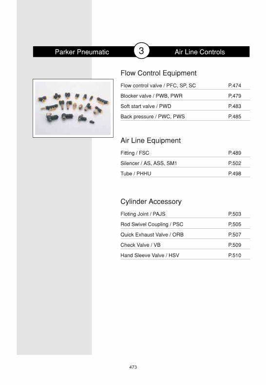
473 Parker Pneumatic Air Line Controls P.489 P.502 P.498 Fitting / FSC Silencer / AS, ASS, SM1 Tube / PHHU Air Line Equipment P.474 P,479 P.483 P.485 Flow control valve / PFC, SP, SC Blocker valve / PWB, PWR Soft start valve / PWD Back pressure / PWC, PWS Flow Control Equipment P.503 P,505 P.507 P.509 P.510 Floting Joint / PAJS Rod Swivel Coupling / PSC Quick Exhaust Valve / ORB Check Valve / VB Hand Sleeve Valve / HSV Cylinder Accessory 3
Transcript of Parker Pneumatic Air Line Controls...
473
Parker Pneumatic Air Line Controls
P.489
P.502
P.498
Fitting / FSC
Silencer / AS, ASS, SM1
Tube / PHHU
Air Line Equipment
P.474
P,479
P.483
P.485
Flow control valve / PFC, SP, SC
Blocker valve / PWB, PWR
Soft start valve / PWD
Back pressure / PWC, PWS
Flow Control Equipment
P.503
P,505
P.507
P.509
P.510
Floting Joint / PAJS
Rod Swivel Coupling / PSC
Quick Exhaust Valve / ORB
Check Valve / VB
Hand Sleeve Valve / HSV
Cylinder Accessory
3

474
PFC 2 One touch fitting built-inMeter-out type
1. Series 4. Port SizeM5
1/8
1/4
3/8
1/2
M5
1/8"
1/4"
3/8"
1/2"
2. Body Size
1
2
3
4
M5
1/8", 1/4"
1/4", 3/8"
1/2"
3. Tube Diameter04
06
08
10
12
4 mm
6 mm
8 mm
10 mm
12 mm
12 bar
9.9 bar
5~60
Air
Nylon, Polyurethan
M5,1/8,1/4,3/8,1/2
4, 6, 8, 10, 12
Description Material
1 Body Resin
2 Body Brass
3 Needle Brass
4 Lock Nut Brass
5 Handle Brass
6 U packing NBR
7 O-ring NBR
Flow Control ValveM5,1/8,1/4,3/8,1/2
1
2
3
4
5
6
7
7
SpecificationOrdering Insturction
Construction
Symbol
PFC 06021 2Proof Pressure
Max Using Pressure
Fiuid
Temperature Range
Material
Port Size
Appl icable Tube diameter(mm)

DimensionPFC Series
Flow Cotrol Valve(One touch fitting built-in)
475
A
TUBE
H
T
L
PFC12-04-M5
PFC12-06-M5
PFC22-04-1/8
PFC22-06-1/8
PFC22-08-1/8
PFC22-04-1/4
PFC22-06-1/4
PFC22-08-1/4
PFC22-10-1/4
PFC22-12-1/4
PFC32-06-3/8
PFC32-08-3/8
PFC32-10-3/8
PFC32-12-3/8
PFC42-10-1/2
PFC42-12-1/2
33.7
33.7
44.3
44.3
44.3
44.3
44.3
44.3
47.6
47.6
47.6
52
52
52
61.3
61.3
37
37
48.6
48.6
48.6
48.6
48.6
48.6
52
52
52
57.5
57.5
57.5
67.2
67.2
Model NoL
Max Min
4
6
4
6
8
4
6
8
10
12
6
8
10
12
10
12
TubeDiameter
16.8
17.6
16.8
17.6
18.7
16.8
17.6
18.7
19.6
21.9
17.6
18.7
19.6
21.9
19.6
21.9
26.6
27.2
31.5
32.4
39.2
34.8
35.6
37.7
37.9
39.2
40.9
42.7
43.6
45.9
45.6
48.3
H
4.6
4.6
8
8
8
10
10
10
10
10
11
11
11
11
14
14
A
08 x 9.24
08 x 9.24
Nut
14 x 16.1
14 x 16.1
14 x 16.1
17 x 19.6
17 x 19.6
17 x 19.6
17 x 19.6
17 x 19.6
21 x 24.2
21 x 24.2
21 x 24.2
21 x 24.2
24 x 27.7
24 x 27.7
M5 x 0.8P
M5 x 0.8P
PT1/8
PT1/8
PT1/8
PT1/4
PT1/4
PT1/4
PT1/4
PT1/4
PT3/8
PT3/8
PT3/8
PT3/8
PT1/2
PT1/2
T F
(Unit : mm)

476
04
06
08
10
12
4 mm
6 mm
8 mm
10 mm
12 mm
12
9.9
5~60
Air
Nylon, Polyurethan
4, 6, 8, 10, 12
MPa(bar)
mm
(Unit : mm)
PFC25 06
PFC25-04
PFC25-06
PFC25-08
PFC25-10
PFC25-12
Model No
29.9
35
37.4
43.8
467.4
L
Min Max
33.3
39.5
42.1
49
53.6
Mountinghole( )
3.3
4.3
4.4
4.4
4.4
H
45.1
50.3
55.7
61.2
69.8
Tube
4
6
8
10
12
Tube insertlength
16.8
17.6
18.7
19.6
21.9
(F)
PFC25 In- line TypeOne touch fitting built-in
Flow Control Valve4, 6, 8, 10, 12
L
Mounting hole
1. Series 2. Tube Diameter
SpecificationOrdering Insturction
Dimension
Symbol
Proof Pressure
Max Using Pressure
Temperature Range
Fluid
Material
Appl icable Tube diameter(mm)

477
Cylinder Controller
SP SeriesFlow Control Valve / In-Line Type
SP-H-M5Symbol
Specification
DimensionFlow Characteristics
Unit SP-H-M5
PT
Mpa(bar)
M5 X 1.0
1mm2
Air
0 ~ 0.8 ( 0 ~ 8.0)
-5 ~ 60
g 10
(Unit : mm)
In-Line TypePort Size M5
Note)
0 1 2 3 4 5
5
15
10
20
25
6 7 8 9 10
l/min (ANR)
Number of needle rotation
0.1Mpa0.2Mpa
0.4Mpa
0.6Mpa
5.5 10
.9
3.9
13.5
13.5
25.5
8.0
Series
Port Size
Effective area
Fluid
Using pressure Range
Temperature Range
Weight

478
Cylinder Controller
Flow Control Valve / In-Line Type
SC320SC330SC340
Symbol
Specification
Dimension
Unit SC320-08 SC330-10 SC340-15
Rc(PT)
Free FlowAir Flow
Effective Area
Air Flow
Effective Area
/min
340 800 1650
mm2
/min
mm2 5 12 24
ControlledFlow
250 800 1650
3.7 12 24
Air
0.5~0.9
0~60
g 115 125 240
Series A B C D E G H L
SC320-08 40 27 18 31 31 18 18 5
SC330-10 56 33 24 45 32 25 21 5.5
SC340-15 66 38 29 54 39 29 24 6
(Unit : mm)
L
MIN
XM
AX
Y
2-PT
H
C
2- S
D
B
A
G
2-CME
PT S X Y CM
1/4 4.6 52 56 M3X0.5P dp6
3/8 5.6 63.5 69 M4X0.7P dp9
1/2 5.6 79 87 M5X0.8P dp8
IN-Line TypePort Size Rc
IN-Line TypePort Size Rc
IN-Line TypePort Size Rc
SC Series
Series
Port Size
Fluid
Using Pressure Range
Temperature Range
Weight

479
Cylinder Controller
Blocker ValvePWB-A Series
PWB-A14PWB-A18
Pilot Port-Push in Type /Supply Port-Push in Type
Pilot Port-Thread Type /Supply Port-Thread Type
Pilot Operating Pressure
ClassPilot operating pressure Pilot release pressure
2 bar 4 bar 6 bar 8 bar 2 bar 4 bar 6 bar 8 bar
2.30 2.70 3.05 3.40 1.50 1.80 2.15 2.40
2.30 2.70 3.05 3.40 1.50 1.80 2.15 2.40
2.45 2.75 3.05 3.40 1.40 1.70 2.00 3.50
3.05 3.40 3.70 4.05 1.75 2.10 2.40 2.80
Specification
ORDER KEY
Symbol
Air Circuit
Unit PWB-A
0 ~ 10
Air
-15 ~ 60
1Million ( 6bar/20 -1Hz )
10
Zine alloy
Brass alloy
bar
Hz
Body
Mounting
4206
6
8
8
12
12
0.15550
1300 0.18
2300 0.50
Max.Flow(l/min)
Weight(kg)
Max.Flow(l/min)
Weight(kg)
Order key
Order key CylinderPort
TubePort(mm)
PWB-A1468
PWB-A1469
PWB-A1489
PWB-A1483
PWB-A1493
PWB-A1412
BSPP(G)
4200.18
550
1300 0.19
BSPP(G)
PWB-A1898
PWB-A1899
PWB-A1833
PWB-A1822
PT
PWB-A18982
PWB-A18992
PWB-A18332
PWB-A18222 2300 0.48
Blocker
BlockerPilot Pressure
PWB-A14692
PWB-A14892
PWB-A14832
PWB-A14932
PWB-A14122
R(PT)
CylinderPort
FemalePort
Class
Operating rpessure
Permissible fluids
Operating temperature
Mehanical life
Frequency
Material
480
Cylinder Controller
ı AH
K
B
L
HEX C
ı AH
K
B
L
HEX C
HEX C
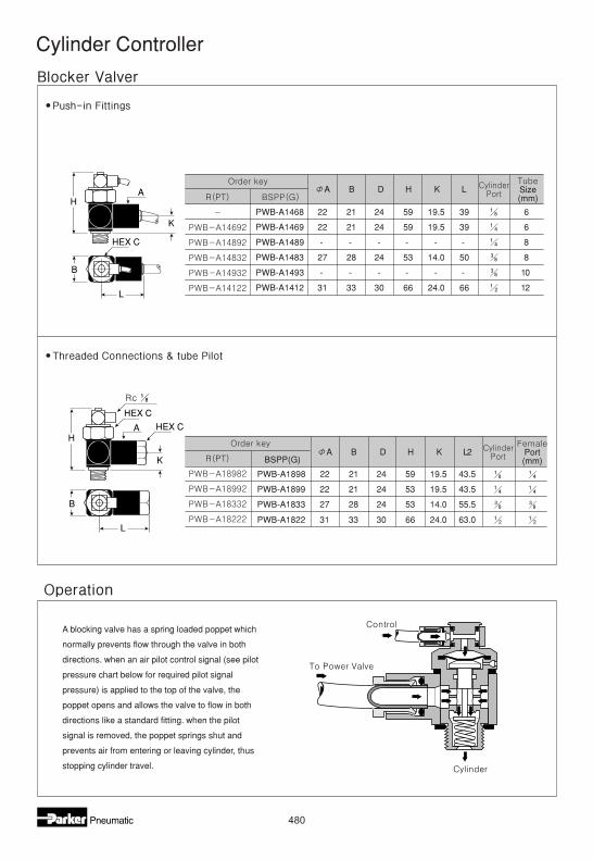
A B D H K L
PWB-A1468 22 21 24 59 19.5 39
PWB-A1469 22 21 24 59 19.5 39
PWB-A1489 - - - - - -
PWB-A1483 27 28 24 53 14.0 50
PWB-A1493 - - - - - -
PWB-A1412 31 33 30 66 24.0 66
A B D H K L2
PWB-A1898
BSPP(G)
22 21 24 59 19.5 43.5
PWB-A1899 22 21 24 53 19.5 43.5
PWB-A1833 27 28 24 53 14.0 55.5
PWB-A1822 31 33 30 66 24.0 63.0
6
6
8
8
10
12
Size(mm)
Port(mm)
A blocking valve has a spring loaded poppet which
normally prevents flow through the valve in both
directions. when an air pilot control signal (see pilot
pressure chart below for required pilot signal
pressure) is applied to the top of the valve, the
poppet opens and allows the valve to flow in both
directions like a standard fitting. when the pilot
signal is removed, the poppet springs shut and
prevents air from entering or leaving cylinder, thus
stopping cylinder travel.
481
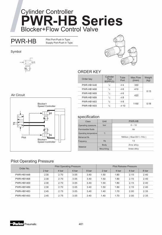
Blocker+Flow Control Valve
PWR-HB Pilot Port-Push in TypeSupply Port-Push in Type
Pilot Operating Pressure
2 bar 4 bar 6 bar 8 bar 2 bar 4 bar 6 bar 8 bar
specification
ORDER KEY
Symbol
Air Circuit
Unit PWR-HB
bar 0 ~ 10
Air
1Million ( 6bar/20 -1Hz )
Hz 10
Body Zine alloy
Mounting brass alloy
PWR-HB1448
PWR-HB1468
PWR-HB1469
PWR-HB1489
PWR-HB1483
PWR-HB1493
3304
6
6
8
8
10
0.13410
420
1150 0.18
Max.Flow(l/min)
Weight(kg)Order key
CylinderPort
BSPP(G)
TubePort
Blocker+Speed Controller
Blocker+Speed Controller
Pilot
Order No.Pilot Operating Pressure Pilot Release Pressure
PWR-HB1448 2.30 2.70 3.05 3.40 1.50 1.80 2.15 2.40
PWR-HB1468 2.30 2.70 3.05 3.40 1.50 1.80 2.15 2.40
PWR-HB1469 2.30 2.70 3.05 3.40 1.50 1.80 2.15 2.40
PWR-HB1489 2.30 2.70 3.05 3.40 1.50 1.80 2.15 2.40
PWR-HB1483 2.45 2.75 3.05 3.40 1.40 1.70 2.00 2.35
PWR-HB1493 2.45 2.75 3.05 3.40 1.40 1.70 2.00 2.35
Cylinder Controller
PWR-HB Series
Class
Operating rpessure
Permissible fluids
Operating temperature
Mehanical life
Frequency
Material

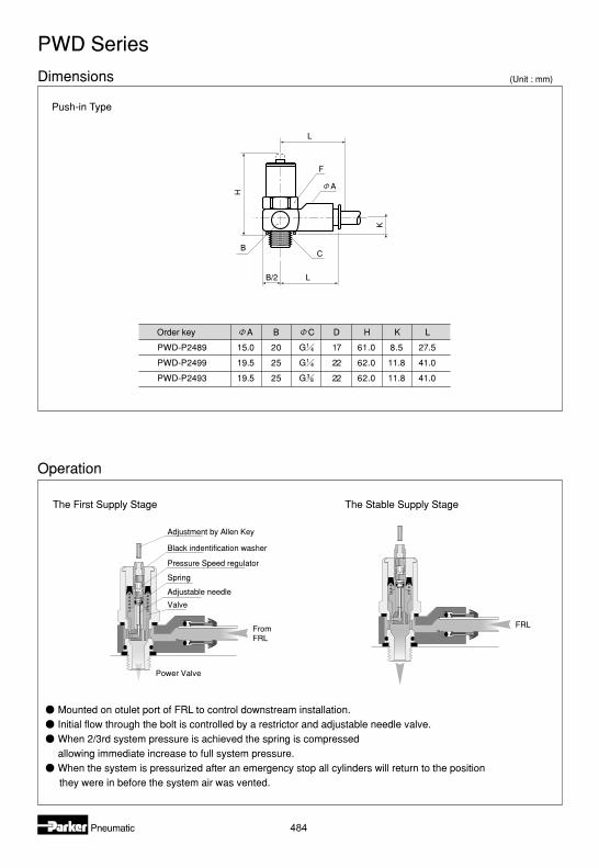
Dimensions
Pilot operated diaphragm maintains fullflow when pilot signal is present.Spring Closes the poppet valve locking airin the cylinder when the pilot signal is removed.Prestobloc fittings used in conjunction withPrestoflow flow regulators are mounted on inletand outlet ports.Pilot signal should be independent fromthe control valve.
Pilot control
DiaphragmFlow control adjuster
Flow controllocknut
To powervalve
Spring
482
Cylinder
Poppet valve
Blocker+Flow Control
Order key A B D H K L P
PWR-HB-1448 22.5 21 24 59 19.5 47.0 12.5
PWR-HB-1468 22.5 21 24 59 19.5 47.0 12.5
PWR-HB-1469 22.5 21 24 53 13.5 47.0 12.5
PWR-HB-1489 22.5 21 24 53 13.5 47.0 12.5
PWR-HB-1483 29.0 28 24 53 15.5 60.0 15.0
PWR-HB-1493 29.0 28 24 53 15.5 60.0 15.0
C
G
G
G
G
G
G
E
4
6
6
8
8
10
H
B
L
C
P
K
A
PWR-HB Series
Operation
C
E
(Unit : mm)

483
Slow Start Flow Control Valve
Cylinder Controller
PWD-P SeriesPWD-P Push-in Type
Soft Start Valve
Specification
ORDER KEY
Pressure Graph
Symbol
Air Circuit
Adjustment
Unit PWD-P
bar 0 ~ 10
Air
- 15 ~ + 60
1Million( 6bar/20 -1Hz )
Hz 10
Body Zine alloy
Mounting Brass alloy
PWD-P2489
PWD-P2499
PWD-P2493
1500
2000
2000
8
10
10
0.070
0.120
0.130
Max.Flow(l/min)
Weight(kg)
CylinderPort
BSPP(G)TubePort
Order key
No
Con
trol
AdjustableTime
P
SupplyPressure
Full Flow
With slow-starter
Time
Spanner
AdjustmentUse a spanner to prevent the bolt
assembley turning.
Use an Allen key to adjust the
needle valve.
Maximum torque 1N/m.
Class
Operating rpessure
Permissible fluids
Operating temperature
Mehanical life
Frequency
Material
484
Dimensions
Operation
Push-in Type
Order key A B C D H K L
PWD-P2489 15.0 20 G 17 61.0 8.5 27.5
PWD-P2499 19.5 25 G 22 62.0 11.8 41.0
PWD-P2493 19.5 25 G 22 62.0 11.8 41.0
HB
C
F
A
L
K
B/2 L
The First Supply Stage The Stable Supply Stage
FRL
Adjustment by Allen Key
Pressure Speed regulator
Spring
Adjustable needle
Valve
Black indentification washer
FromFRL
Power Valve
PWD Series
(Unit : mm)
Mounted on otulet port of FRL to control downstream installation.Initial flow through the bolt is controlled by a restrictor and adjustable needle valve.When 2/3rd system pressure is achieved the spring is compressedallowing immediate increase to full system pressure.When the system is pressurized after an emergency stop all cylinders will return to the positionthey were in before the system air was vented.
485
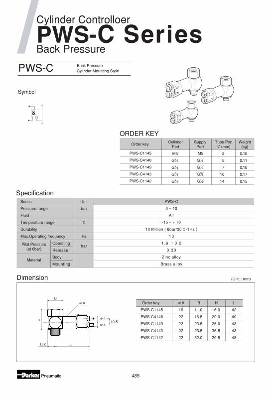
Cylinder Controlloer
Back Pressure
PWS-C Back PressureCylinder Mounting Style
Symbol
ORDER KEY
PWS-C1145
PWS-C4148
PWS-C1149
PWS-C4143
PWS-C1142
2
5
7
10
14
M5
G
G
G
G
M5
G
G
G
G
0.10
0.11
0.10
0.17
0.15
Weight(kg)
CyilnderPort
SupplyPort
Tube Port(mm)
Order key
Dimension
H
LB/2
410.5
4
BA Order key A B H L
PWS-C1145 19 11.0 16.0 42
PWS-C4148 22 16.5 29.0 40
PWS-C1149 22 23.5 26.0 43
PWS-C4143 22 23.5 36.5 43
PWS-C1142 22 32.0 29.5 48
SpecificationUnit
bar
bar
Hz
Body
Mounting
Operating
Release
PWS-C
0 ~ 10
Air
-15 ~ + 70
10 Million ( 6bar/20 -1Hz )
10
1 .6 0 .2
0 .30
Zinc alloy
Brass alloy
PWS-
Series
Pressure range
Fluid
Temperature range
Durability
Max.Operating frequency
(Unit : mm)
Pilot Pressure(at 6bar)
Material
486
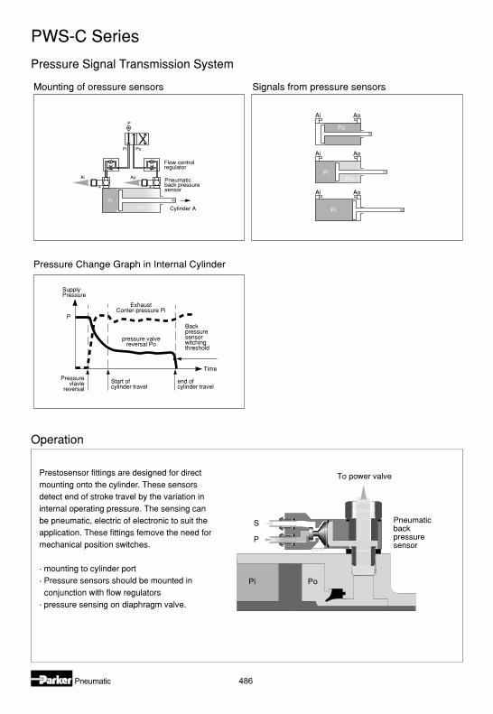
Pressure Signal Transmission System
Prestosensor fittings are designed for directmounting onto the cylinder. These sensorsdetect end of stroke travel by the variation ininternal operating pressure. The sensing canbe pneumatic, electric of electronic to suit theapplication. These fittings femove the need formechanical position switches.
. mounting to cylinder port
. Pressure sensors should be mounted inconjunction with flow regulators
. pressure sensing on diaphragm valve.
To power valve
PoPi
S
P
Pneumaticbackpressuresensor
Pressurevlavle
reversal
Backpressuresensorwitchingthreshold
SupplyPressure
ExhaustConter-pressure Pi
Start ofcylinder travel
end ofcylinder travel
pressure valvereversal Po
Time
P
P
Pi Po
Po
Pi
Ai Ao
Flow controlregulator
Pneumaticback pressuresensor
Cylinder A
Mounting of oressure sensors
Pressure Change Graph in Internal Cylinder
Po
PoPi
Pi
Ai Ao
Ai Ao
Ai Ao
Signals from pressure sensors
Operation
PWS-C Series
487
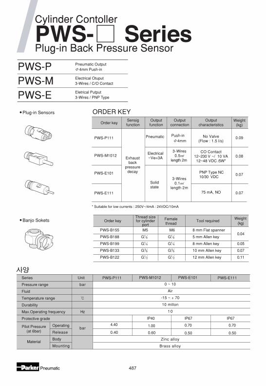
Cylinder Contoller
Plug-in Back Pressure Sensor
PWS-PPWS-MPWS-E
Pneumatic Output4mm Push-in
Electrical Otuput3-Wires / C/O Contact
Eletrical Putput3-Wires / PNP Type
Plug-in Sensors
Banjo Sokets
* Suitable for low currents : 250V~/4mA : 24VDC/10mA
Order keySensigfunction
Outputfunction
Outputconnection
Outputcharacteristics
Weight(kg)
PWS-P111
Exhaustback
pressuredecay
Pneumatic Push-in4mm
No Valve(Flow : 1.5 l/s)
CO Contact12~230 V ~/ 10 VA12~48 VDC /5W*
0.09
PWS-M1012 Electrical~Ve=3A
3-Wires0.5
length 2m0.08
PWS-E101
Solidstate
3-Wires0.1
length 2m
PNP Type NC10/30 VDC
0.07
PWS-E111 75 mA, NO 0.07
Order keyThread sizefor cylinder
port
Femalethread
Tool requiredWeight
(kg)
PWS-B155 M5 M6 8 mm Flat spanner0.04
PWS-B188 G G 5 mm Allen key
PWS-B199 G G 8 mm Allen key 0.05
PWS-B133 G G 10 mm Allen key 0.07
PWS-B122 G G 12 mm Allen key 0.11
4.40
0.40
1.00
0.60
0.70
IP67IP40 IP67
0.50
0.70
0.50
PWS-P111 PWS-M1012 PWS-E111PWS-E101Unit
Pilot Pressure(at 6bar)
Material
bar
bar
Hz
Body
Mounting
Operating
Release
0 ~ 10
Air
-15 ~ + 70
10 millon
10
Zinc alloy
Brass alloy
PWS- Series
ORDER KEY
Series
Pressure range
Fluid
Temperature range
Durability
Max.Operating frequency
Protective grade

488
Dimension
Back Pressure Sensors
32 2m
18 X 14
Screw
Locking clipØ4 mm push-inconnection
Black (BK)
Black (BK)
Blue (BU)
Blue (BU)
Brown (BN)
Brown (BN)
Banjo sokect
Plug-in sensor
All back pressure sensors are a comination of two distinct parts : a banjo socket + a plug-in sensor
2220
Order key C B H K L
PWS-B155 8 11 16.5 10 17.0
PWS-B188 5 16 20.0 10 20.0
PWS-B199 8 21 20.0 10 22.0
PWS-B133 10 28 22.0 12 25.0
PWS-B122 12 33 26.0 14 26.0
H
K 18.5
24.5
C
B
LB/2
32 2m
16
Connection
Assembly
PWS-M : Breaking pressure = 0.5 bar
BU
BK
BN
Wire :bbb
Black (BK)
Blue (BU)
Brown (BN)
N/C Contact N/O Contact
+1 BN
-3 BU
2BK
C1
+1 BN
-3 BU
4BK
C1
PWS-E : Pilot pressure = 0.5 bar
Wire :blackbluebrown
Black (BK)
Blue (BU)
Brown (BN)
Cylinder Controller
(Unit : mm)

489
Fitting Series

490
Kind of Connector
Fitting Series

491
Fitting Series
( )Tube insert
depth F

492
Fitting Series
T
( )Tube insert
depth F
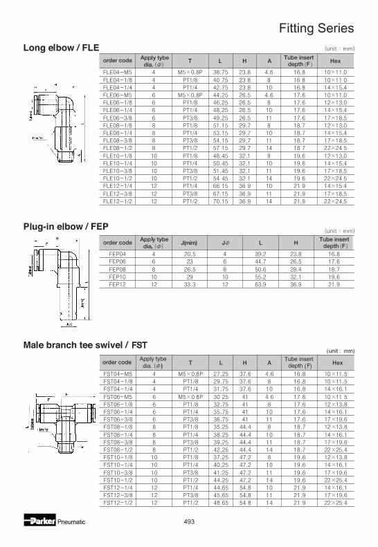
493
Fitting Series
(unit : mm)Apply tybedia. ) ( )
Tube insertdepth F

494
Fitting Series
(unit : mm)

495
Fitting Series

496
Fitting Series
(unit : m m )

497
Fitting Series
Apply tybedia. ( )
(unit : mm)
order code¥

498
SilencerM5, R , R , R , R
Specification ORDER KEY
Dimension
1. SeiresSilencer
2. Port size
6
8
10
15
M5
1/8
1/4
3/8
1/2
AS 6
Symbol
5
AS - 5AS - 6AS - 8AS - 10AS - 15
(Unit : mm)
R(PT)
L
TB
A
ASS-8
ASS-10
ASS-15
ASS-6
ASS-5
65
30.5
21.5
25.5
16.5
14
10
13
7
95
85
41
2
2
2
2
A
8
B
- 11
L
-
T
M5
R(PT)Order key
Unit AS-5 AS-6
PT M5 1/8
mm 2 4 16
Air
-5~60
dB 30 or less
g 3 6
AS-8
1/4
40
13
AS-10
3/8
80
21
AS-15
2/1
106
33
Model No.
Port Size
Effective area
Fluid
Temperature range
Noise
Weight
499
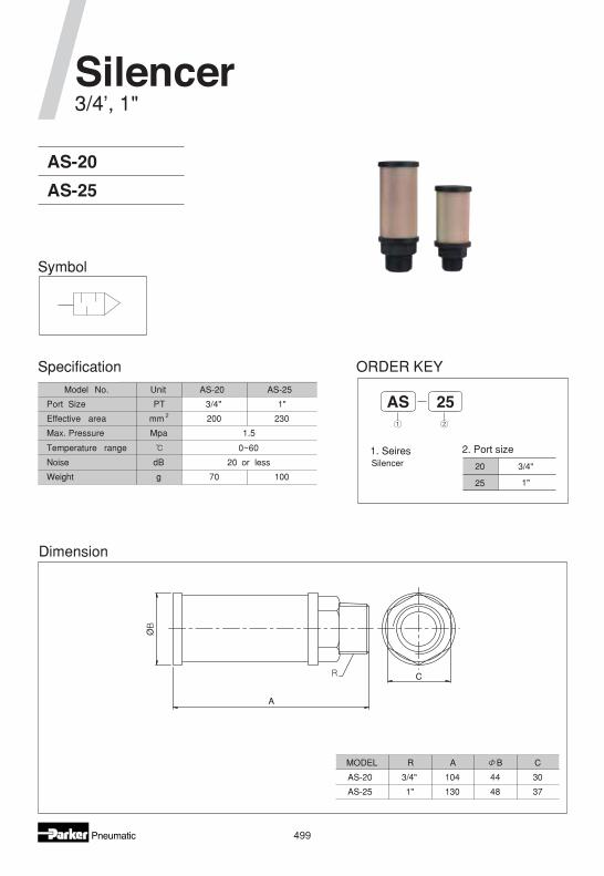
Silencer3/4', 1"
Specification ORDER KEY
Dimension
1. SeiresSilencer
2. Port size
25
3/4"
1"
AS 25
Symbol
20
AS-20
AS-25
A
Ø
C
Model No. Unit AS-20 AS-25
Port Size PT 3/4" 1"
Effective area mm 2 200 230
Max. Pressure Mpa 1.5
Temperature range 0~60
Noise dB 20 or less
Weight g 70 100
MODEL R A B C
AS-20 3/4" 104 44 30
AS-25 1" 130 48 37
500
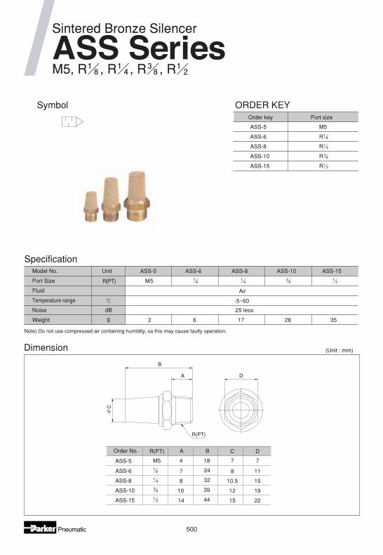
Specification
Note) Do not use compressed air containing humidity, sa this may cause faulty operation.
Dimension
Symbol
(Unit : mm)
Unit ASS-8 ASS-10 ASS-15ASS-5
M5
Air
-5~60
25 less
R(PT)
dB
g
ASS-6
3528172 6
Model No.
Port Size
Fluid
Temperature range
Noise
Weight
Sintered Bronze Silencer
ASS SeriesM5, R , R , R , R
ASS-8
ASS-10
ASS-15
ASS-6
ASS-5
10.5
14
8
10
7
44
32
39
24
15
12
8
22
19
15
11
A
4
B
18 7
C
7
D
M5
R(PT)Order No.
R(PT)
C
A
B
D
Order key Port size
ASS-5
ASS-6
ASS-8
ASS-10
ASS-15
M5
R
R
R
R
ORDER KEY
501
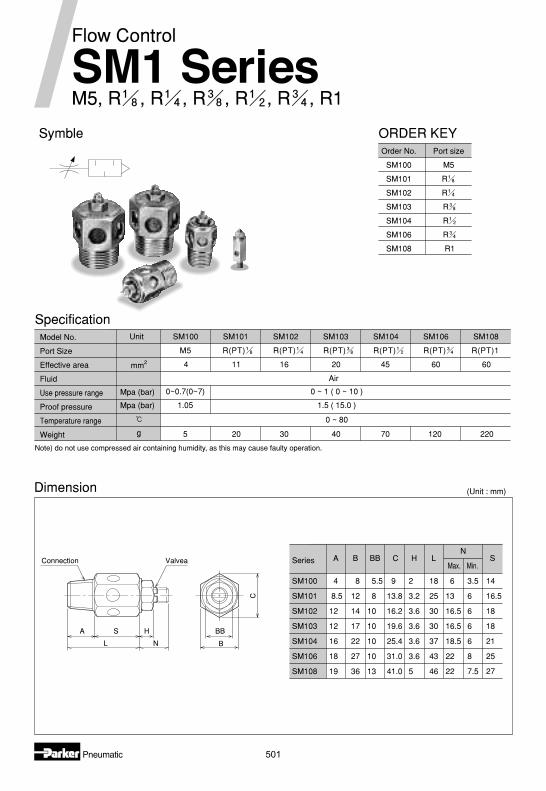
SM1 Series
Note) do not use compressed air containing humidity, as this may cause faulty operation.
Dimension (Unit : mm)
M5, R , R , R , R , R , R1
Flow Control
Model No.
Port Size
Effective area
Fluid
Use pressure range
Proof pressure
Temperature range
Weight
SpecificationUnit
R(PT) R(PT) R(PT)1R(PT)R(PT)M5
Air
Mpa (bar)
Mpa (bar)
g
R(PT)
0 ~ 80
SM100
4
SM101
11
SM102
16
SM103
20
SM104
45
SM106
60
SM108
60
5 4020 30 70 120 220
0 ~ 1 ( 0 ~ 10 )
1.5 ( 15.0 )
0~0.7(0~7)
1.05
mm2
Order No.
SM100
SM101
SM102
SM103
SM104
SM106
SM108
Port size
M5
R
R
R
R
R
R1
ORDER KEY
A
SM100
Series
SM101
SM102
SM103
SM104
SM106
SM108
4
8.5
12
12
16
18
19
8
12
14
17
22
27
36
5.5
8
10
10
10
10
13
B BB C
9
13.8
16.2
19.6
25.4
31.0
41.0
2
3.2
3.6
3.6
3.6
3.6
5
H
18
25
30
30
37
43
46
6
13
16.5
16.5
18.5
22
22
3.5
6
6
6
6
8
7.5
LMax. Min.
NS
14
16.5
18
18
21
25
27
Symble
Connection
A S BB
B
C
H
L N
Valvea
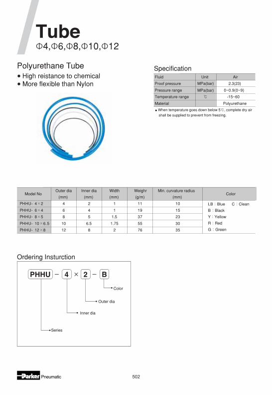
Polyurethane Tube
502
When temperature goes down below 5 , complete dry air
shall be supplied to prevent from freezing.
Specification
Ordering Insturction
Fluid AirUnit
MPa(bar)
MPa(bar)
Proof pressure 2.3(23)
Pressure range 0~0.9(0~9)
Temperature range -15~60
Material Polyurethane
Model NoOuter dia
(mm)
Inner dia
(mm)
Width
(mm)
Weighr
(g/m)
Min. curvature radius
(mm)Color
PHHU- 4 2 4 2 1 11 10 LB Blue C Clean
B Black
Y Yellow
R Red
G Green
PHHU- 6 4 6 4 1 19 15
PHHU- 8 5 8 5 1.5 37 23
PHHU- 10 6.5 10 6.5 1.75 55 30
PHHU- 12 8 12 8 2 76 35
PHHU 4 2 B
Color
Outer dia
Inner dia
Series
4, 6, 8, 10, 12Tube
High reistance to chemicalMore flexible than Nylon

503
Series
Screw bore
Model No.
Screw bore
Screw direction
Temperature range
Oscillation angle
Radial deflection
Allowable tension
Model No.
Screw bore
Screw dinection
Temperature range
Oscillation angle
Radial deflection
Allowable tension
Unit
Unit
Floating Joint
PAJS SeriesORDER KEY
Specifications
504
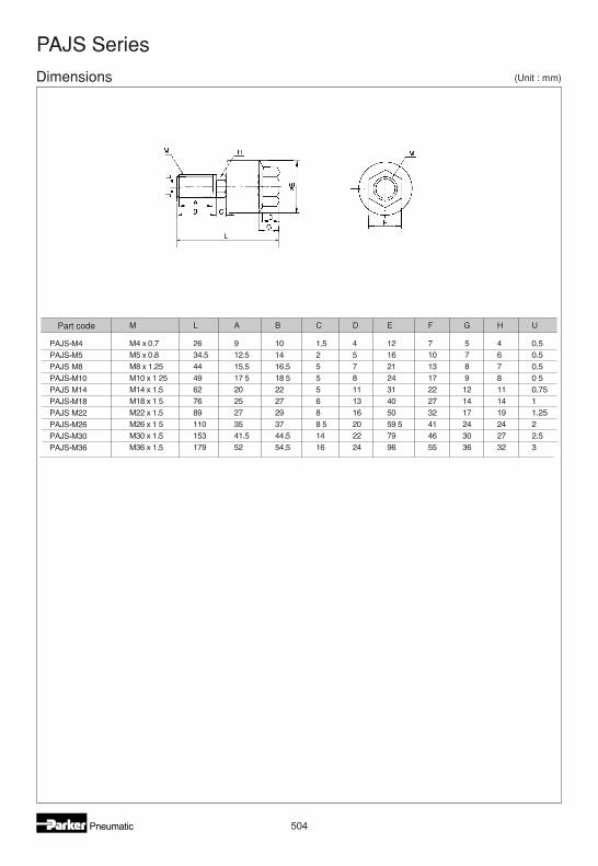
PAJS Series
L
Dimensions
Part code
(Unit : mm)

505
Weight
Temperature range
Rod Swivel Coupling
PSC Series
ORDER KEY
Specifications
506
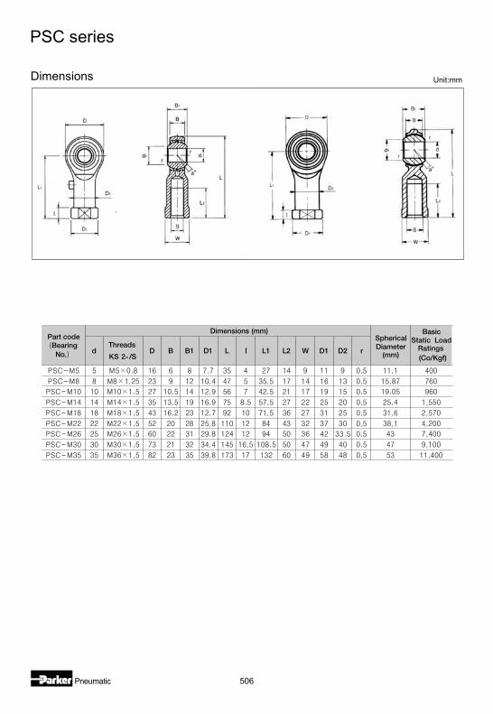
PSC series
Dimensions Unit:mm
507
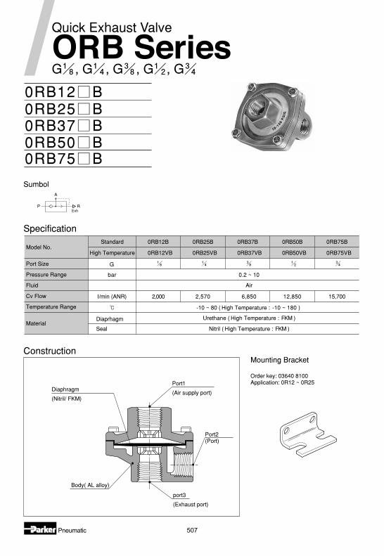
Construction
Specification
Mounting Bracket
Order key: 03640 8100Application: 0R12 ~ 0R25
0RB12 B0RB25 B0RB37 B0RB50 B0RB75 B
Model No.Standard
High Temperature
0RB12B 0RB25B 0RB37B 0RB50B 0RB75B
0RB12VB 0RB25VB 0RB37VB 0RB50VB 0RB75VB
bar 0.2 ~ 10
Air
I/min (ANR) 2,000 2,570 6,850 12,850 15,700
Seal
DiaprhagmMaterial
Nitril ( High Temperature : FKM )
Urethane ( High Temperature : FKM )
-10 ~ 80 ( High Temperature : -10 ~ 180 )
SumbolA
P RExh
Port1
(Air supply port)Diaphragm
(Nitril/ FKM)
Port2(Port)
port3
(Exhaust port)
Body( AL alloy)
Quick Exhaust Valve
G , G , G , G , GORB Series
Port Size
Pressure Range
Fluid
Cv Flow
Temperature Range
G
508
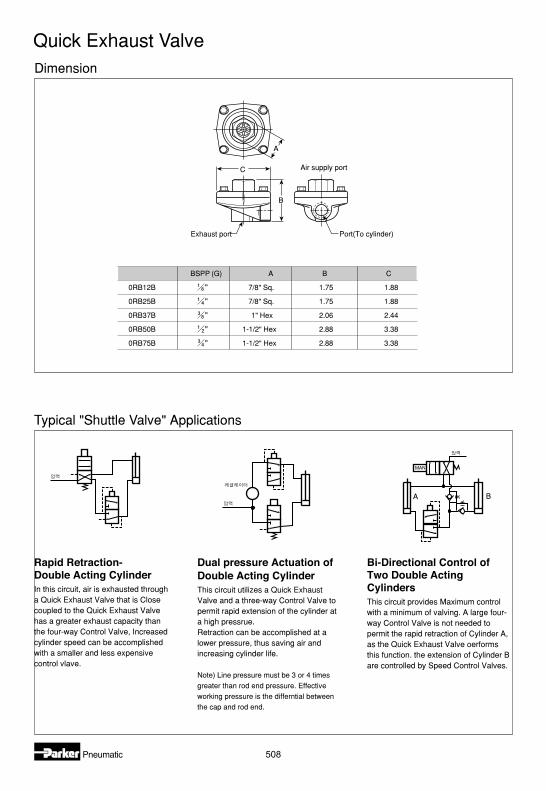
Quick Exhaust ValveDimension
Typical "Shuttle Valve" Applications
C
A
B
Air supply port
Exhaust port Port(To cylinder)
BSPP (G) A C
"0RB12B 7/8" Sq. 1.75 1.88
0RB25B 7/8" Sq. 1.75 1.88"
"0RB37B 1" Hex 2.06 2.44
"0RB50B 1-1/2" Hex 2.88 3.38
"0RB75B 1-1/2" Hex 2.88 3.38
B
MAN
A B
Rapid Retraction-Double Acting CylinderIn this circuit, air is exhausted througha Quick Exhaust Valve that is Closecoupled to the Quick Exhaust Valvehas a greater exhaust capacity thanthe four-way Control Valve, Increasedcylinder speed can be accomplishedwith a smaller and less expensivecontrol vlave.
Bi-Directional Control ofTwo Double ActingCylindersThis circuit provides Maximum controlwith a minimum of valving. A large four-way Control Valve is not needed topermit the rapid retraction of Cylinder A,as the Quick Exhaust Valve oerformsthis function. the extension of Cylinder Bare controlled by Speed Control Valves.
Dual pressure Actuation ofDouble Acting CylinderThis circuit utilizes a Quick ExhaustValve and a three-way Control Valve topermit rapid extension of the cylinder ata high pressrue.Retraction can be accomplished at alower pressure, thus saving air andincreasing cylinder life.
Note) Line pressure must be 3 or 4 times
greater than rod end pressure. Effective
working pressure is the differntial between
the cap and rod end.

509
Non return valve
VB12-Q-NQ-5
VB22-Q-NQ-5VB42-Q-NQ-5
1. SeriesNon return valve
2. Port Size
VB 12 Q NQ 5
Model No. Uni t VB12 VB22 VB42
Port Size G1/8 G1/4 G1/2
Operating pressure bar 10 bar
Fluid used Air Water
Temperature Range -20 ~70
Weight g 10 10 50
Model No F L N
VB12-Q-NQ-5 G1/8 31 14
VB22-Q-NQ-5 G1/4 40 17
VB42-Q-NQ-5 G1/2 59 27
12 G1/8
22 G1/4
42 G1/2
(Unit : mm)
L
N F
Specification
Symbol
ORDER KEY Dimensions
Rugged brass or aluminium bodiesNitrile or viton optionsLow 0.1 bar operating pressursFul flow one direction onlyCompact design
510
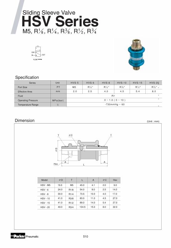
Dimension (Unit : mm)
41.0
8.0
5.4
4.5
4.0
2.5
2.0
15.0
14.0
11.0
10.0
8.0
4.1
104.5
89.0
83.0
73.5
54.0
45.0
49.0
41.0
30.0
24.0
R3/4
R1/2
R3/8
R1/4
R1/8
M5
HSV - 15
HSV - 20
HSV - 10
HSV - 8
Model
HSV - 6
CT AL
19.0
D
HSV - M5
32.0
27.0
27.0
17.0
14.0
9.0
Hex
TCT
HexAA
L
D
SpecificationUnit
PT
mm
MPa(bar)
-730mmHg ~ 60
0 ~ 1.0 ( 0 ~ 10 )
Air
R "R "M5 R " R " R "
HVS-5 HVS-6 HVS-8 HVS-10 HVS-15 HVS-20Series
Port Size
Effective Area
Fluid
Operating Pressure
Temperature Range
IN
EXH
OUT
FLOW
Sliding Sleeve Valve
HSV SeriesM5, R , R , R , R , R
2.0 2.5 4.0 4.5 5.4 8.0