Parker Piston Pumps - Heino Winter · Parker Piston PumpsParker Piston Pumps. ... instead of at the...
53
Hydraulic Pump/Motor Division Parker Piston Pumps Parker Piston Pumps Parker Piston Pumps
-
Upload
truonghanh -
Category
Documents
-
view
227 -
download
8
Transcript of Parker Piston Pumps - Heino Winter · Parker Piston PumpsParker Piston Pumps. ... instead of at the...

Hydraulic Pump/Motor DivisionHydraulic Pump/Motor Division
Parker Piston PumpsParker Piston PumpsParker Piston Pumps

Hydraulic Pump/Motor Division
Otsego Core Competency...
Hydraulic Pump/Motor Division
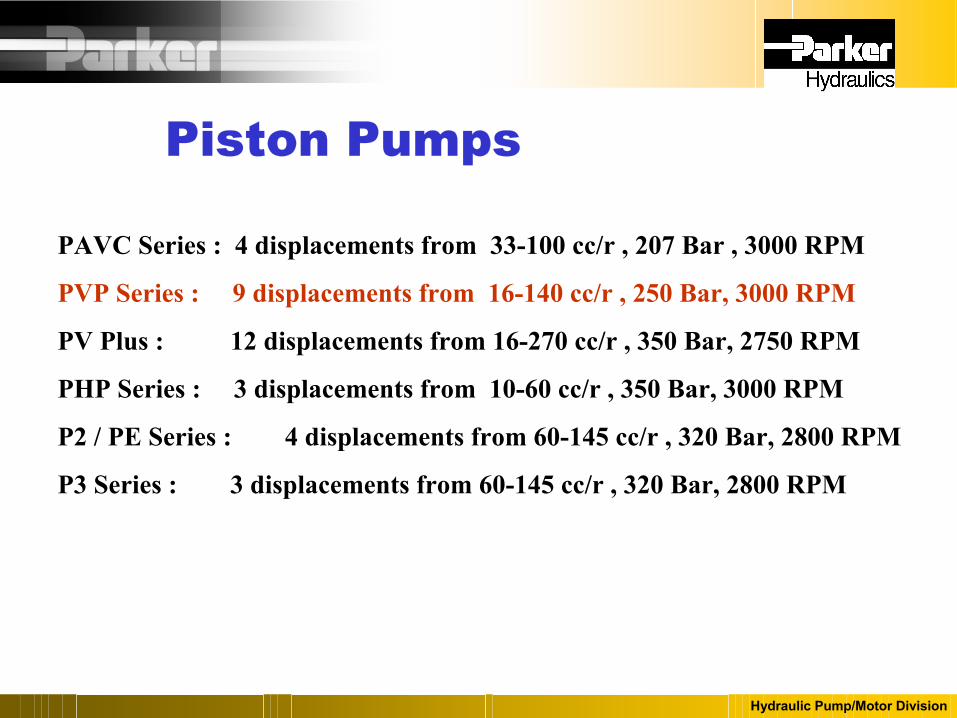
PAVC Series : 4 displacements from 33-100 cc/r , 207 Bar , 3000 RPM
PVP Series : 9 displacements from 16-140 cc/r , 250 Bar, 3000 RPM
PV Plus : 12 displacements from 16-270 cc/r , 350 Bar, 2750 RPM
PHP Series : 3 displacements from 10-60 cc/r , 350 Bar, 3000 RPM
P2 / PE Series : 4 displacements from 60-145 cc/r , 320 Bar, 2800 RPM
P3 Series : 3 displacements from 60-145 cc/r , 320 Bar, 2800 RPM
Piston Pumps
Hydraulic Pump/Motor Division
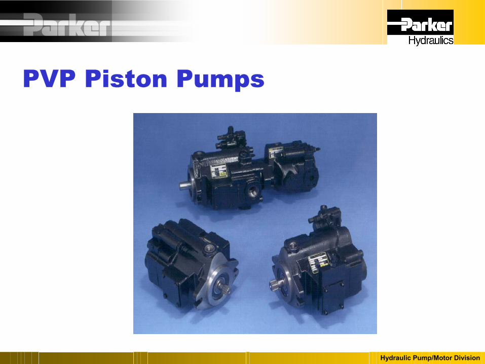
PVP Piston Pumps

Hydraulic Pump/Motor Division
PVP100/140???
• PVP100/140 phase out – This model has been removed from the 2003 list
price guide.– PVP100/140’s are available as replacements for
current applications.• Pricing is available from your sales coordinator.
– Currently there has been no date set for the final phase out of the PVP100/140.
• PE105 & PE145 is the replacement.– These models should be used for new
applications and as upgrades to existing applications if the change can be made.
Change to…
PE105 / 145
PVP100 / 140

Hydraulic Pump/Motor Division
PVP60/76???
• PVP60/76 phase out – This model will be removed from the 2004 list
price guide.– PVP60/76’s will be available as replacements for
current applications.• Pricing will be available from your sales
coordinator.– Currently there has been no date set for the final
phase out of the PVP60/76.• PE60 & PE075 is the replacement.
– These models should be used for new applications and as upgrades to existing applications if the change can be made.
Change to…
PE60/75
PVP60/76

Hydraulic Pump/Motor Division
PVP Pump Series
Hydraulic Pump/Motor Division
Displacement cc/rev. 16 23 33 41 48Max Pressure Continuous (psi) 3600 3600 3600 3600 3600Max Pressure Peak (psi) 4500 4500 4500 4500 4500Self Priming Speed (rpm) 3000 3000 3000 2800 2400
Hydraulic Pump/Motor Division
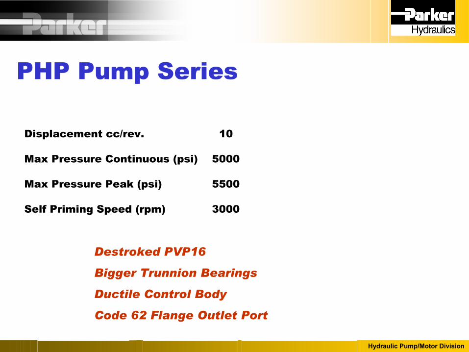
PHP Pump Series
Hydraulic Pump/Motor Division
Displacement cc/rev. 10
Max Pressure Continuous (psi) 5000
Max Pressure Peak (psi) 5500
Self Priming Speed (rpm) 3000
Destroked PVP16
Bigger Trunnion Bearings
Ductile Control Body
Code 62 Flange Outlet Port

Hydraulic Pump/Motor Division
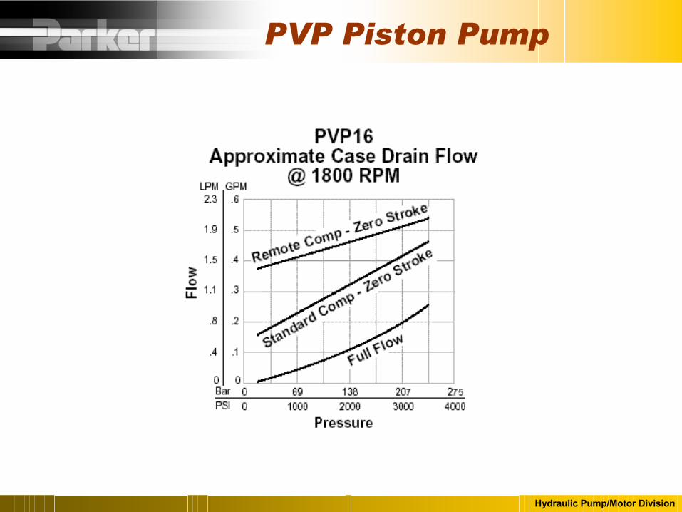
PVP Piston Pump
Hydraulic Pump/Motor Division
PVP Piston Pump

Hydraulic Pump/Motor Division
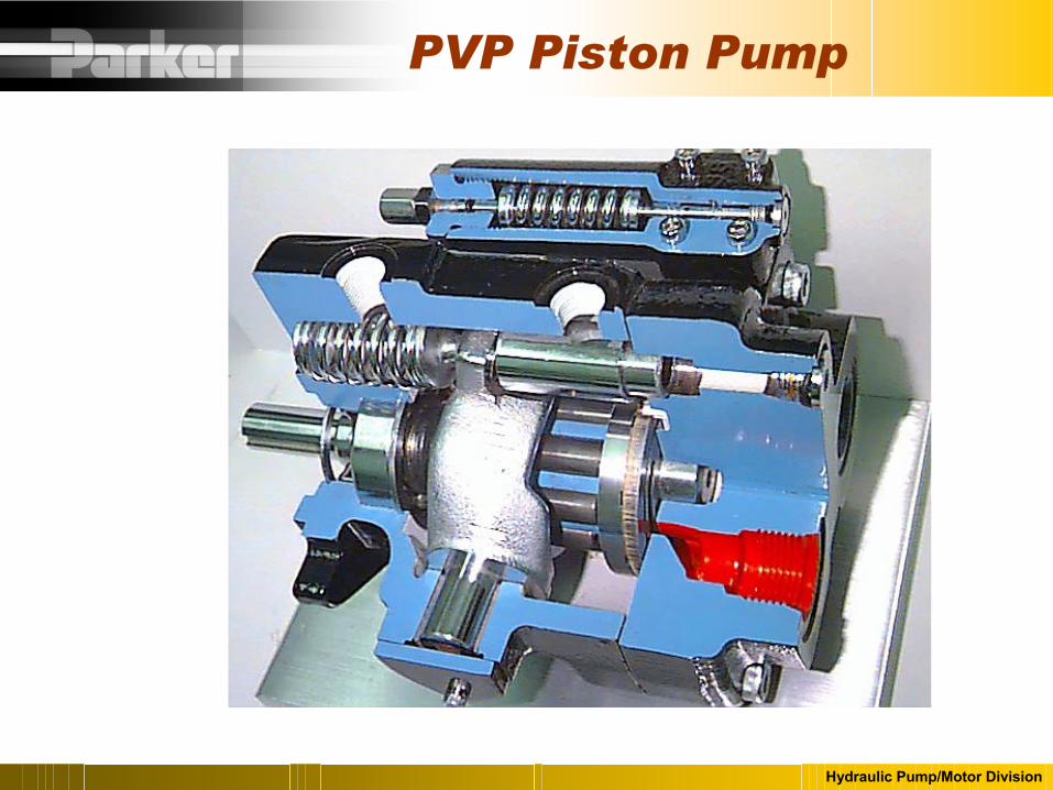
PVP Piston Pump
Designed For Low Noise Levels
- Cast Iron Housing
- Heavy duty “DU” trunnion bearings
- 9 Pistons - PVP16, 23, 33
- 11 Pistons - PVP41, 48

Hydraulic Pump/Motor Division
PVP Piston Pump
Designed For Low Noise
Full Flow Full Flow
@ 1200 RPM @ 1800 RPM- PVP16 56 dBa 62 dBa
- PVP23/33 65 dBa 70 dBa
- PVP41/48 68 dBa 75 dBa

Hydraulic Pump/Motor Division
PVP Piston Pump
Designed For Fast Response
On Stroke Off Stroke- PVP16 100 ms 50 ms
- PVP23/33 70 ms 40 ms
- PVP41/48 100 ms 50 ms

Hydraulic Pump/Motor Division
PVP Piston Pump
Designed For Serviceability
- Replaceable bronze wear plate
- Replaceable piston slipper plate
- PVP23/33/41/48
- Service shaft, bearing and seal without disassembling the pump.
- Modular controls

Hydraulic Pump/Motor Division
PVP Piston Pump
Designed For Flexibility- Variety of Ports and Mounting Shaft Options
- Thru – Drives Available All Sizes
- PVP16 : SAE “AA” , “A”
- PVP23/33/41/48: SAE “AA” , “A” , “B” , “BB”
- Variety of controls
- Pressure Compensator
- Remote Pressure Compensator
- Load Sense
- Torque Control
Hydraulic Pump/Motor Division
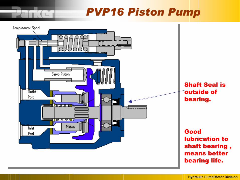
PVP16 Piston Pump
Shaft Seal is outside of bearing.
Good lubrication to shaft bearing , means better bearing life.

Hydraulic Pump/Motor Division
Shaft Seal is inside of sealed bearing .
Can change shaft without disassembling the pump.
Better on water glycol fluid.
PVP23/33/41/48 Piston Pump

Hydraulic Pump/Motor Division
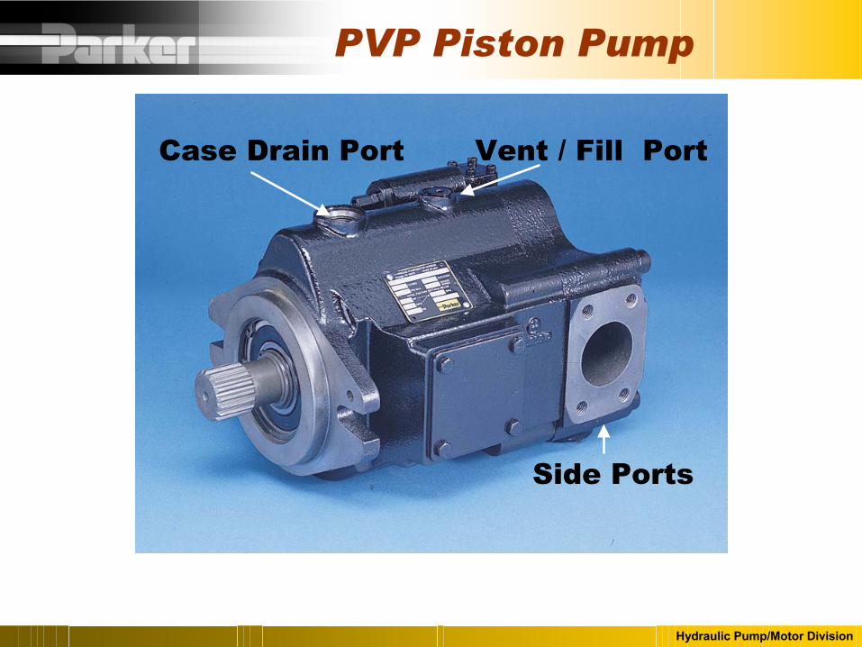
PVP Piston Pump
Case Drain Port
Rear Inlet & Outlet Ports
Vent / Fill Port
Hydraulic Pump/Motor Division
Side Ports
Case Drain Port
PVP Piston Pump
Vent / Fill Port

Hydraulic Pump/Motor Division
PVP Piston Pump
“9”“9”“9”Metric SideFlange(BSPP)
“8”“8”“8”Metric SideFlange(6149)
“3”“3”“4”Side PortsStr. Thread
“2”“2” “2”Side Ports
Flange
N/AN/A“5” Rear PortsVickers
“Omit”“Omit”“Omit”Rear Ports
41/4823/3316Port Options

Hydraulic Pump/Motor Division
Port Spacing Same as Eaton Vickers PVB 5/6
Case Drain
Inlet Port
Outlet Port
Direct Mounting Interchange with Vickers PVB5/6
PVP16 “5” Port Option
Alternate Case Drain on Bottom
.38 “ Shorter than standard rear port PVP16

Hydraulic Pump/Motor Division
PVP Piston Pump
1 inch, Code 61 4 Bolt Flange
1-1/4, Code 61 4 Bolt Flange
3/4 “, Code 614 Bolt FlangeSide Outlet Flange
SAE 47/16-20 UNF
SAE 47/16-20 UNF
SAE 47/16-20 UNFSignal Port
SAE 107/8-14 UNF
SAE 89/16-20 UNF
SAE 69/16-18 UNCCase Drain
1-1/2 inch, Code 61 4 Bolt Flange
1-1/4, Code 61 4 Bolt Flange
3/4 “, Code 614 Bolt FlangeSide Inlet Flange
SAE 241-7/8-12 UNC
SAE 201-5/8-12 UNC
SAE 121-1/16-12 UNCRear Inlet Threaded
SAE 161-5/16-12 UNC
SAE 201-5/8-12 UNC
SAE 121-1/16-12 UNCRear Outlet Threaded
41/4823/3316Port Connections
There are metric equivalents readily available

Hydraulic Pump/Motor Division
PVP Piston Pump

Hydraulic Pump/Motor Division
PVP Piston Pump

Hydraulic Pump/Motor Division
PVP Piston Pump
Hydraulic Pump/Motor Division
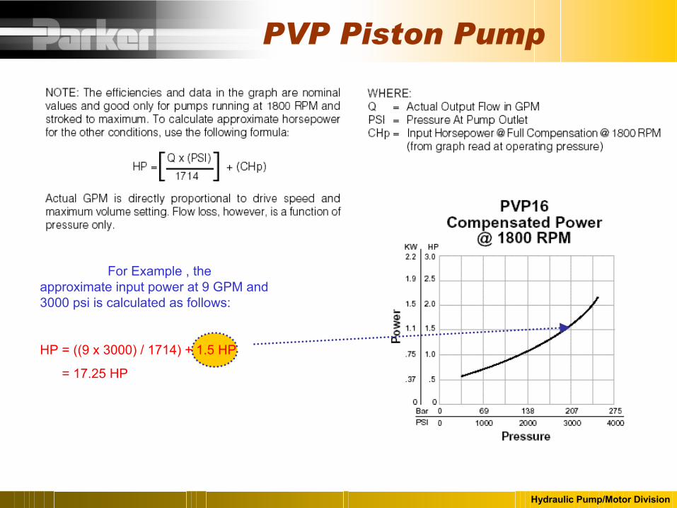
For Example , the approximate input power at 9 GPM and 3000 psi is calculated as follows:
HP = ((9 x 3000) / 1714) + 1.5 HP
= 17.25 HP
PVP Piston Pump
Hydraulic Pump/Motor Division
PVP Piston Pump

Hydraulic Pump/Motor Division
PVP Piston Pump
Case Drain Line Must Run Unrestricted back to the reservoir.
Maximum Back Pressure at the Case Drain Port is 10 PSI.
High Case Pressure can cause slipper roll which can lead to catastrophic failure.

Hydraulic Pump/Motor Division
Compensator AdjustmentCompensator Spring
Bias Spring
Case Pressure
Why can high case pressure cause slipper roll???

Hydraulic Pump/Motor Division
o Pressure Compensator The pressure compensator control will limit pump
outlet pressure to a predetermined level and adjust pump outlet flow to the level needed to maintain the set pressure.
o Remote Pressure Compensator
Same as the pressure compensator , except that the adjustment is done with a remotely located relief valve instead of at the pump control.
o Load Sense Control
Load sense control will adjust output flow to maintain a constant pressure drop across an orifice.
Torque Limiter Control
Will adjust flow to limit the input torque demand of the pump.
PVP Pump Controls

Hydraulic Pump/Motor Division
PVP Pressure Compensator
Adjustment
Pressure Compensator

Hydraulic Pump/Motor Division
PVP Controls
Pressure Compensator
Same Controls used on PVP16/23/33/41/48
Compensators can be selected with a maximum pressure adjustment of 1000, 2000, 3000, 3600 PSI
Minimum Pressure Compensator setting is 250 psi.
550 PSI per turn

Hydraulic Pump/Motor Division
PVP Controls
Pressure Compensator
View Shows Pressure is below the Compensator Setting and the Pump is at Full Stroke.

Hydraulic Pump/Motor Division
PVP Controls
Pressure Compensator
View Shows Outlet Pressure has reached the Compensator Setting and the Pump has Destroked.

Hydraulic Pump/Motor Division
Remote compensator allows control of pump from a remote location using a relief valve located in a different location.
Remote Compensator
PVP Controls

Hydraulic Pump/Motor Division
PVP Controls
Remote Pressure Compensator
Same Controls used on PVP16/23/33/41/48
Compensators can be selected with a maximum pressure adjustment of 1000, 2000, 3000, 3600 PSI
Remote Compensator flow is .5 GPM.
Differential Spring is Factory Set at 150 PSI
940 PSI per turn

Hydraulic Pump/Motor Division
“M” Master & “ME” Slave Controls
Compensators of two pumps plumbed together, “ME” comp set higher than “M”
Safety in case one pump fails.
Higher flows than available with one pump
PVP Controls

Hydraulic Pump/Motor Division
Master Slave Arrangement, To Combine pump flows, use one “M” compensator and one “ME” compensator. Use a hose to tie the two compensators together and the two pumps will track each other , providing a smooth operating system. Without this arrangement , the pumps may become unstable.
PVP Controls

Hydraulic Pump/Motor Division
Alternate Remote Control Ports for M Option
PVP Controls
Orifice Plug 800599
.034”
Hydraulic Pump/Motor Division
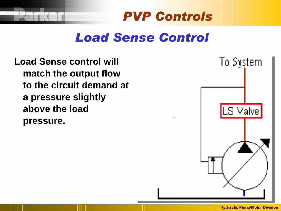
Load Sense control will match the output flow to the circuit demand at a pressure slightly above the load pressure.
Load Sense Control
PVP Controls
Hydraulic Pump/Motor Division
PVP Controls
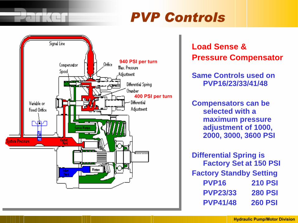
Load Sense & Pressure Compensator
Same Controls used on PVP16/23/33/41/48
Compensators can be selected with a maximum pressure adjustment of 1000, 2000, 3000, 3600 PSI
Differential Spring is Factory Set at 150 PSI
Factory Standby SettingPVP16 210 PSIPVP23/33 280 PSIPVP41/48 260 PSI
940 PSI per turn
940 PSI per turn
400 PSI per turn

Hydraulic Pump/Motor Division
PVP Controls
Pressure
Flow
TheoreticalConstant HP
Torque Limiter Pump Curve
Torque Limiter Control

Hydraulic Pump/Motor Division
PVP with Torque Control

Hydraulic Pump/Motor Division
.
Torque Limiter & Load Sense with Pressure Compensator
Model Code “ C”
Modular Style
Customer needs to specify the setting desired in HP at a particular drive speed and compensator setting.
PVP with Torque Control

Hydraulic Pump/Motor Division
PVP Torque ControlNote:
Performance at
other drive speeds
can be extrapolated

Hydraulic Pump/Motor Division
PVP Torque ControlNote:
Performance at
other drive speeds
can be extrapolated
Note There is a High/Low Control for the PVP41 /48 that allows the pump to reach higher pressures at low horsepower settings, but it is very difficult to field set in mobile applications.

Hydraulic Pump/Motor Division
Hi / Lo Horsepower Control

Hydraulic Pump/Motor Division
Hi/Lo Horsepower Control

Hydraulic Pump/Motor Division
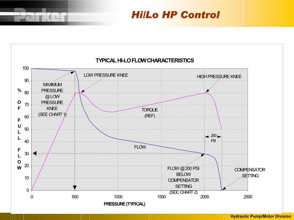
Hi/Lo HP Control
TYPICAL HI-LO FLOW CHARACTERISTICS
0
10
20
30
40
50
60
70
80
90
100
0 500 1000 1500 2000 2500PRESSURE (TYPICAL)
% OF FULL FLOW
200PSI
FLOW @ 200 PSI BELOW
COMPENSATOR SETTING
(SEE CHART 2)
MAXIMUM PRESSURE
@ LOW PRESSURE
KNEE(SEE CHART 1)
LOW PRESSURE KNEE HIGH PRESSURE KNEE
TORQUE(REF)
FLOW
COMPENSATOR SETTING
Hydraulic Pump/Motor Division
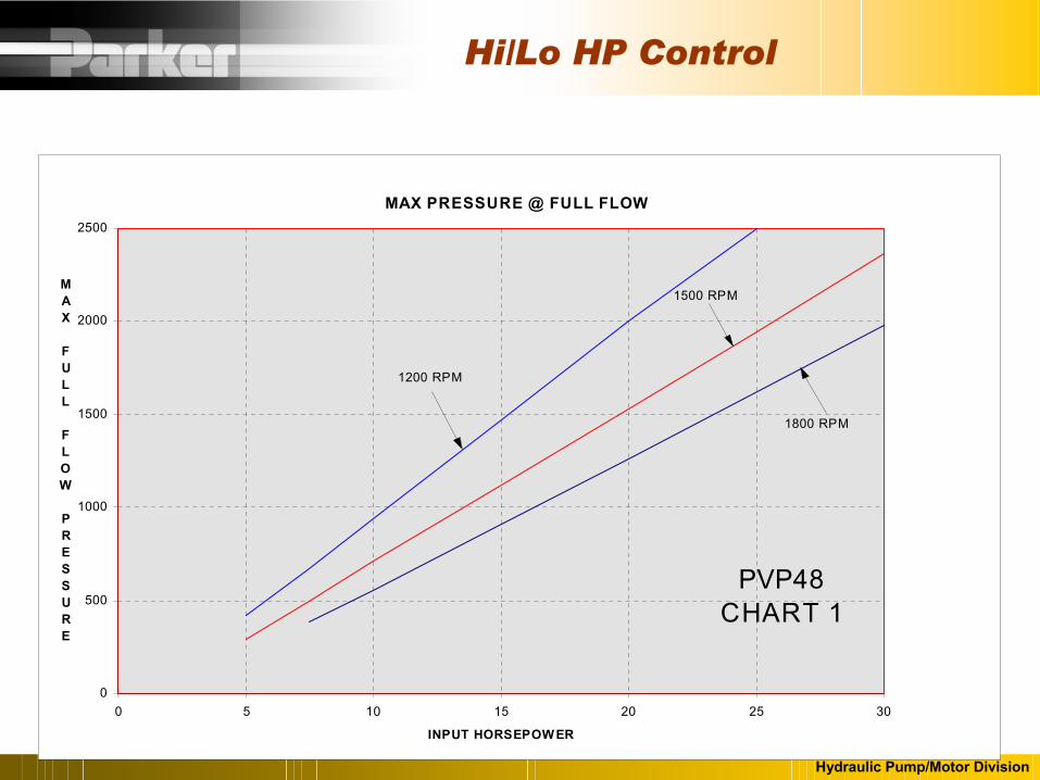
Hi/Lo HP Control
MAX PRESSURE @ FULL FLOW
0
500
1000
1500
2000
2500
0 5 10 15 20 25 30
INPUT HORSEPOWER
MAX FULL FLOW PRESSURE
1800 RPM
1500 RPM
1200 RPM
PVP48 CHART 1
Hydraulic Pump/Motor Division
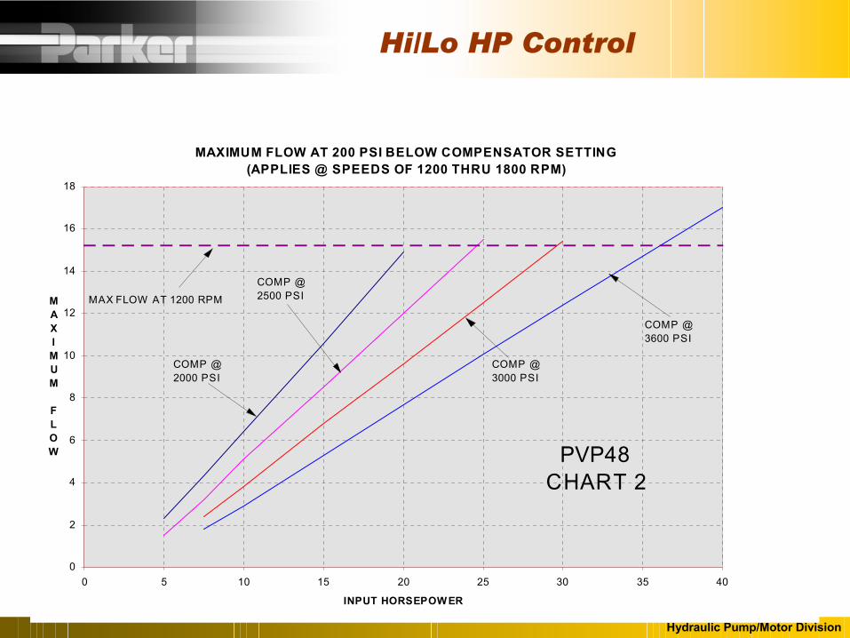
Hi/Lo HP Control
MAXIMUM FLOW AT 200 PSI BELOW COMPENSATOR SETTING(APPLIES @ SPEEDS OF 1200 THRU 1800 RPM)
0
2
4
6
8
10
12
14
16
18
0 5 10 15 20 25 30 35 40
INPUT HORSEPOWER
MAXIMUM FLOW
COMP @3000 PSI
COMP @ 3600 PSI
COMP @ 2500 PSI
COMP @ 2000 PSI
PVP48 CHART 2
MAX FLOW AT 1200 RPM
Hydraulic Pump/Motor Division
Hi/Lo HP Control
TYPICAL HI-LO FLOW CHARACTERISTICS
0
10
20
30
40
50
60
70
80
90
100
0 500 1000 1500 2000 2500PRESSURE (TYPICAL)
% OF FULL FLOW
200PSI
FLOW @ 200 PSI BELOW
COMPENSATOR SETTING
(SEE CHART 2)
MAXIMUM PRESSURE
@ LOW PRESSURE
KNEE(SEE CHART 1)
LOW PRESSURE KNEE HIGH PRESSURE KNEE
TORQUE(REF)
FLOW
COMPENSATOR SETTING

Hydraulic Pump/Motor Division
Thank you!!!