
Parker Chainless Challenge - University of Minnesota€¦ · Parker Chainless Challenge Hydraulic...
24
Parker Chainless Challenge Hydraulic Bicycle, Volume I ME 4054: Senior Design, Fall 2012 Sponsor: Parker-Hannifin Advisor: Brad Bohlmann Professor: James Van de Ven Tan Cheng Joe Janiszewski Aaron Jasken Brent Wassell Ang Zheng
Transcript of Parker Chainless Challenge - University of Minnesota€¦ · Parker Chainless Challenge Hydraulic...

Parker Chainless Challenge Hydraulic Bicycle, Volume I
ME 4054: Senior Design, Fall 2012 Sponsor: Parker-Hannifin Advisor: Brad Bohlmann
Professor: James Van de Ven
Tan Cheng Joe Janiszewski Aaron Jasken Brent Wassell
Ang Zheng

Executive Summary Chainless Challenge, Volume II
2
Executive Summary The goal of this project is to design and build a bicycle that uses hydraulics as its main power
transmission. It will be designed to compete in the Parker-Hannifin Chainless Challenge in Irvine, CA, in
April of 2013. There are many constraints from Parker, such as the requirement that there is a penalty if
metal chains are used. The competition includes three race events: a long distance race, a short sprint
race, and an efficiency challenge. The purpose of the Chainless Challenge is both to promote interest in
hydraulics and see if a hydraulic design could potentially be a marketable venue for them to explore.
The project functions as a fantastic senior design project which is seen at many Universities across the
nation that brings engineers together to accomplish some amazing tasks.
A hydraulic bicycle was designed around 5 main requirements: a chainless design, the ability to finish
and compete in all races, optimized for user safety, utilization of renewable/recovery energy design,
ability to be used by a single rider.
The final design, Figure ES.2, consists of a three-wheeled recumbent trike frame with custom mountings
for a pump, motor, accumulator, reservoir, and valves. An 8 speed internal gear hub was mounted in
the rear to allow the rider to take off from a dead stop more easily, and output more torque at higher
speeds. Additionally, the integration of cogged-belts with custom sprockets was used to overcome the
chainless design restrictions from Parker.
The hydraulic circuit, Figure ES.1, was designed with 3 different modes of operation. The first mode,
cruise mode, exists so that the rider pedals which turns the pump which turns the motor which turns the
wheel. The bike is in this mode in its native state. With the integration of solenoids, fluid flow can be
diverted where desired to allow for different modes of use. The second mode is charge mode, in which
flow to the motor is cut off and the flow is directed into the accumulator to store energy. In the third
mode, release mode, the energy and pressure is released from the accumulator to the motor. This
allows the bike to be propelled without pedaling.
Figure ES.1 – Finished Bicycle with components Figure ES.2 – Hydraulic Circuit
While the entire project is built, assembled and working, further testing and optimization needs to occur
in order that they bike can be ready for competition in April of 2013.

Executive Summary Chainless Challenge, Volume II
3
Table of Contents Executive Summary ....................................................................................................................................... 2
1 – Problem Definition .................................................................................................................................. 4
1.1 – Problem Scope ................................................................................................................................. 4
1.2 – Technical Review .............................................................................................................................. 4
1.3 – Design Requirements ..................................................................................................................... 10
2 – Design Description ................................................................................................................................ 11
2.1 – Summary of Design ........................................................................................................................ 11
2.2 – Detailed Description ....................................................................................................................... 12
2.3 – Additional Uses .............................................................................................................................. 20
3 – Evaluation .............................................................................................................................................. 21
3.1 – Evaluation Plan ............................................................................................................................... 21
3.2 – Evaluation Results .......................................................................................................................... 22
3.3 – Discussion ....................................................................................................................................... 23

1 – Problem Definition Chainless Challenge, Volume II
4
1 – Problem Definition
1.1 – Problem Scope The scope of this project involves designing, building, testing, and optimizing a completely chainless hydraulic bicycle with an energy regeneration/recovery system. The bicycle will not be specifically designed for commercialization, but rather for competition in the Parker Hannifin “Chainless Challenge” to be held in April, 2013. The Chainless Challenge is a national competition sponsored by Parker Hannifin - a leading hydraulics manufacturer. In order to be eligible for competition, teams must present a bicycle which is completely driven by fluid power. The bike will then be used to compete in three separate competitions in which the cumulative point total will be used in conjunction with additional categories to determine the overall competition winner. As a project/semester culmination, a design showcase will be held at the ME 4054 Senior Design Show on December 12, 2012.
1.2 – Technical Review The following section provides information regarding the overview and background of the fluid power industry as a whole, a description of the various hydraulic components used throughout the design process, and a description of all prior art/patents identified. Overview/Background of Fluid Power Field Fluid power, in addition to mechanical and electrical power, is one of the three most common types of power transfer systems being used today. Fluid power can be broken down into two main categories: hydraulic, and pneumatic. Hydraulic systems use liquid as the working fluid (usually oil), and pneumatic systems use gas (usually air). The advantage to using fluid power as opposed to these other types of power transmission is the high force density that is associated with fluid power - hydraulics especially. System Characteristics The differences between hydraulic and pneumatic systems are a determining characteristic for the given application. Generally speaking, hydraulics are used in applications that involve heavier loads and operating pressures. This is due to the fact that liquids are not compressible (whereas gasses are) which allows for easier controlled movement of cylinders and motors. Common pressure ranges for hydraulic operations range from approximately 100 - 10,000 psi, and pneumatic operations generally operate between 50 - 140 psi [1]. Fluid Power Industry “The fluid power industry is a broad field and a key contributor to the success of many businesses and industries. Fluid power is extensively used in manufacturing, construction, transportation, agriculture, mining, military operations, health, and even recreation” [1].

1 – Problem Definition Chainless Challenge, Volume II
5
Figure 1.1 – (left) In order to generate enough force to break apart and move concrete, equipment such
as this excavator utilizes hydraulics [1]. Figure 1.2 – (right) Hydraulics are used in many consumer items as well - this garden tractor has a
hydrostatic transmission [1]. Hydraulic Components As stated earlier, in order to compete in the Chainless Challenge, a bicycle which is driven by fluid power must be developed. Due to the fact that hydraulic systems are reliant upon a working fluid, fluid lines and hydraulic components are required to move the fluid throughout the circuit, and for the transfer of energy/power. Fluid power circuits are used similarly to electric circuits to describe the components in a design, and its function overall. It is important to have an understanding of the symbolism used in dealing with the schematics so that proper knowledge of the design process can be obtained. Below is a description of common fluid circuitry components. Pump The pump’s primary purpose within a hydraulic circuit is to create the fluid flow. There are many different types of pumps, ranging from fixed displacement to variable displacement. A fixed displacement pump pushes the exact same amount of fluid through it per revolution. Common pump sizes for an application on this project range from 3 cc/rev to 10 cc/rev (cubic centimeters per revolution). A variable displacement pump is able to change the amount of fluid that is displaced per revolution, but brings with it a more complicated control design to obtain the desired displacement.
Figure 1.3 – Hydraulic schematic symbol for a 1-way pump
Motor A hydraulic motor is essentially the same thing as a pump that works in the opposite direction. Instead of being used to push fluid and introduce flow into the circuit, it takes the existing flow and causes a main drive shaft to rotate. Although variable displacement motors exist they have a lot of complicated control designs.

1 – Problem Definition Chainless Challenge, Volume II
6
Figure 1.4 – Hydraulic schematic symbol for a motor
Accumulator A hydraulic accumulator is essentially a place to store potential energy. There are different types of accumulators, mainly a “spring” design or a “bladder” design. A spring design works by using fluid that is pushed into the accumulator to compress a spring which, in turn, creates potential stored energy. A bladder design uses fluid that is pushed into the accumulator to compress a balloon filled with gas (typically diatomic Nitrogen) as the means to store energy. Accumulators have to be effectively controlled for when to let fluid in (store energy) and when to let fluid out (release energy).
Figure 1.5 – Hydraulic symbol for an accumulator
Reservoir In a hydraulic circuit, a reservoir is used to store extra fluid. In an “open” system, one where the volume of fluid active in the system may change over time, it is essential to have a place for extra fluid. The fluid in a system will change whenever there is an accumulator being used because fluid will be forced in or out of it. Additionally, the reservoir is open to atmospheric pressure so that any pressure in the system will be relative to that.
Figure 1.6 – Hydraulic symbol for a reservoir open to atmospheric pressure
Check Valve In a hydraulic circuit a check valve has one very simple function: only allow flow to go one way. This is analogous to a diode in electric circuits which only allow current to flow in one direction. Check valves are critical to an effective design to make sure that the system functions properly and that “backflow” doesn’t occur. Backflow occurs when fluid flows the wrong direction which, for many applications, is completely undesired and potentially destructive.
Figure 1.7 – Hydraulic symbol for a check valve (flow goes from left to right)

1 – Problem Definition Chainless Challenge, Volume II
7
Relief Valve As with all systems, safety is always a concern. A relief valve is designed to release pressurized fluid into a reservoir if the pressure gets too high. They are essential for a system so that over pressurization does not occur. If the system builds pressure higher than components are rated for, they can explode and cause damage to the system or cause harm to any persons nearby.
Figure 1.8 – Hydraulic symbol for a pressure relief valve
Bicycle Components Because the chainless challenge project involves the integration of a hydraulic power design into a bicycle, it is essential to know the parts of the bicycle so when they are referred to a complete understanding of the system can be obtained.
Figure 1.9 – Standard non-modified recumbent bicycle
Figure 1.9 shows a recumbent bicycle and highlights a lot of the main components. The image shows the bike unmodified, with no integration of any hydraulic parts. For the Chainless Challenge competition, a bicycle similar to the one shown will be highly modified to incorporate a hydraulic drive system.

1 – Problem Definition Chainless Challenge, Volume II
8
Background on Hydraulic Circuits Figure 1.10 shows the core of the integration between the bicycle and the hydraulic circuit. Instead of using human power to turn a chain to drive the back wheel (a standard safety-bike design), the human power will be used to turn a pump, which will then turn a motor, which will then turn the drive wheel. In a standard recumbent bicycle, the back wheel is the primary source for propulsion. Throughout this project alternative options to propel the bicycle will be explored.
Figure 1.10 – Basic system design
Figure 1.11 shows an example circuit that also has energy storage with the addition of an accumulator. Because the system will have to store energy as well as release it, there have been 2 valves added, V1 and V2, respectively. When V1 is closed and V2 is open, the circuit functions similar to that of Figure 10. When V1 is open and V2 is closed, fluid is able to be stored in the accumulator. When V1 and V2 are both open, the system discharged the stored energy in the accumulator. Figure 11 is a basic example of a potential circuit design with energy storage.
Figure 1.11 – Basic system with energy storage
Prior Art Nowadays, sustainable energy is a big topic in science and engineering due to the lack in availability of petroleum oils, and more restrictive emission standards for vehicles. Under such a background, hybrid vehicles and alternatively fueled vehicles have been the focus of many automotive industries and scientific research institutions. Research suggests that the idea of a hydraulic bicycle was first developed in 1936.

1 – Problem Definition Chainless Challenge, Volume II
9
Patent Search
Figure 1.12 – Patent # 3,729,213
Figure 1.12 describes that the most basic idea for the first documented hydraulic bicycle patent was to manually drive a pump via a crank, and transfer the fluid power to the motor at the rear wheel. This motor will then drive the rear wheel and cause it to rotate. For example, in patent # 3,729,213 above, the primary source of fluid power required for the motor’s operation is provided by a pair of hydraulic cylinders powered by the rider’s pedaling. There are also some new ideas about applying the broader hybrid-vehicle concept to bicycles - which provides for a new way of thinking about sustainable energy solutions. As seen in the Figure 13, below, patent # 7,992,948 B2 describes a regenerative braking system assembled into the front hub of a bicycle wheel. This device allows the bicycle to capture part of the kinetic energy that would otherwise be lost while braking, and makes use of that energy to assist accelerating or hill climb maneuvers. A claim is also made that further elaborates on this concept which comprises a remote actuator in communication with the braking mechanism for selecting the mode of operation.
Figure 1.13 – Patent #7,992,948 B2
However, differing from the patents mentioned above, the Chainless Challenge has some particular rules and requirements. Instead of designing the motor and pump specifically for the bike’s use, certain motors and pumps are provided from the project sponsor, Parker-Hannifin. Additionally, the objective is to build a fully functioning vehicle that has excellent stability, controllability, drivability as well as performance. Moreover, commercialization, and manufacturability will also be considered.

1 – Problem Definition Chainless Challenge, Volume II
10
1.3 – Design Requirements Parker-Hannifin, having multiple years organizing the project’s scope, has been able to refine the design requirements to conform to their exact preferences. The overall design parameters have been set by Parker, and been set via the competition criteria. Parker-Hannifin Corporation has provided an eleven page document, “Specifications for Universities Parker 2012/2013 Chainless Challenge [2]”, which explicitly states all of the competition rules and criteria, along with general design parameter requirements. The ultimate goal is to have university teams design, engineer, and produce an efficient, practical, and easily manufactured hydraulically-powered bicycles. Adding to the design requirements this year, Parker has offered bonus points to teams utilizing energy conservation/recovery and/or renewable energy design. The summation of these rules and overall design criterion from Parker-Hannifin are as follows: Chainless Design This design requirement, being implemented from Parker, requires the bike’s design to consist of a hydraulic circuit with a power source being without any metal linked chain at all. In previous years, the chainless design requirement consisted simply of the bike direct drive train to be without chains, where this year, the bike as a whole is to be without metal linked chains. Ability to Finish All Races Given that the primary points available scoring within the competition are from the three different races, one of the major design requirements set by the University team is naturally to be able to successfully and competitively complete each race. The competition’s three races along with race details are as follows:
Long distance: A course totaling of 8.2 miles, goal is to complete course in minimal time as possible.
Efficiency: Bike challenge to test system efficiency. Start challenge with fully charged accumulator, and complete a course with two different stop points. Efficiency of system is calculated based on accumulator size and pressure, along with total distance traveled in course.
Sprint Race: This race consists of a simple standing start, with fully charged accumulators; teams are then timed to see how fast they can accelerate to complete a 200 meter straight course.
Bicycle and System Safety Parker Hannifin having supplied this design requirement, each team’s bike is to be fully inspected by a judging committee prior to any operation. The designs must comply with appropriate safety codes set by Parker, if any safety code is breached the bike will be deemed unsafe and unable to compete. The bicycles will also be disqualified for having a hydraulic system with leaks of 50 drops per minute or greater. Utilization of Renewable/Recoverable Energy Design Parker Hannifin will award 200 bonus points for designs that show “Energy/Conservation/recovery and/or renewable energy design”. Given the broad requirement definition, there is a very wide array of different energy designs to fulfill this requirement which the University's team is currently exploring. Single Rider System Design Parker Hannifin has implemented this rule to regard the race starts. The single rider must be able to supply sufficient torque to the bicycle to overcome system’s resistance. This parameter will fulfill the
2 – Design Description Chainless Challenge, Volume II
11
“standing start” requirement set by the company and will also fulfill practical requirements in regards to manufacturability of the bike. Bicycle Costs less than $4,000 to build The budget is sponsored by Parker Hannifin, which is $4,000 in total. It is very important for us to estimate the total money before implement our plan accurately to avoid overspending. Although the budget may be as high as it is, the University team must still keep manufacturability and marketing potential in mind. If the project becomes overspent it will decrease the value of these parameters in turn yielding a lower competition score.
2 – Design Description The problem at hand is to win the Chainless Challenge. In order to accomplish the main goal, many different criterions will have to be met. The solution is to create an effective design that adheres to all of the competition requirements and also performs well. The competition requirements call for the development of a hydraulic bicycle. In order to score highly in the competition, the bike cannot have metal chains on it. If metal chains are present, a 50pt or 10% deduction in overall score occurs. Because winning the chainless challenge is the main goal, a core design requirement is that the design does not have metal chains. The bike is being designed to compete effectively in 3 different races - a sprint race, a distance race and an “efficiency” race. In order to compete in all of the different races, the bike will have to be equipped with an energy storage element. In hydraulic design, energy storage is most often accomplished with an accumulator. To emphasize the point clearly - the bike will be equipped with an accumulator in order than energy can be stored as to effectively compete in all of the challenges. In order to win the competition, maximum points will have to be obtained. One of the ways to maximize potential points is to have, “Energy conservation/recovery and/or renewable energy design” If those requirements are met, the project will be awarded 200 additional points. Because winning the competition is the team’s main goal, it is absolutely essential to claim the potential 200 points. Therefore, an energy conservation/recovery and/or renewable energy design feature will be in the final design.
2.1 – Summary of Design The final design is an improved version of last year’s vehicle. The team that worked on the bike did a fantastic job designing the bike and system. However, some improvements to the design were critical. The bike as received was a 3-wheel recumbent bicycle, in particular a Greenspeed GT1. This particular frame was chosen after an analysis of different types of frames and models were compared. The frame that was selected last year is incredibly strong and also light as compared to other models. The chainless challenge team this year elected to keep the same frame and improve upon it. One of the major problems was that although the bicycle had a fully implemented hydraulic transmission system, it had metal chains connecting the pedals to the pump as well as the motor to the drive shaft on the rear wheel. Per design requirements and decisions made by the team the metal chains had to be eliminated. After exploring many different options and rating them against each other (see Volume II Table 1.2 for drive type comparison) the team elected to use a carbon-fiber cog belt design. Parker Hannifin confirmed at the orientation meeting that non-metallic cogged belts were an acceptable design option that would not receive a penalty.

2 – Design Description Chainless Challenge, Volume II
12
The bike will be designed to effectively compete in all 3 competitions. At the beginning of each race, the competing teams are allowed to “charge” the bike’s accumulator for 10 minutes. In the energy efficiency race, the team is not allowed to pedal at all and has to use nothing but stored energy to move the bike. These requirements made it obvious to design a hydraulic system that has an energy storage element. In fact, the bike has been designed to have 3 different “modes” of operation. The modes of operation are cruise (normal pedaling/movement), charge (pedaling stores energy) and release (release stored energy). Since the bicycle is designed with different modes of operation, there had to be an effective control system designed that allow for control of the different options. The team determined the easiest way to design the control circuit to adapt to potential future changes is to use an Arduino control system. This allows for easy switching and changing of programming with minimal time in between. There are many different important control system options which had to be considered. One of the main considerations is ease of use. It is critical that the end user can intuitively use the system. In order to have functionality in hydraulic circuits, it is important to control where the flow goes. This is often done by the use of solenoid valves - valves that open or close with current flow. By opening and closing particular valves, the user can control the different modes of operation of the bike. Status LED lights have also been implemented as a notification method so the user knows what mode is actively engaged. Because of all of the electronic components, a battery is required to power the system. One of the big improvements to the bike is the implementation of a renewable energy design. Many different energy renewable designs were explored. The implementation of the renewable energy design also helped solve the other issue of battery power. By using solar panels we can harness the sun’s energy in a renewable design that is also used to charge out battery and make it last longer. The electrical control system is essential to the motive power of the bike - without it the bike will not function properly. Therefore, it is believed that the implementation of an electrical regeneration system is allowed in the Parker Hannifin guidelines for earning 200 additional points in the subcategory of “motive power”.
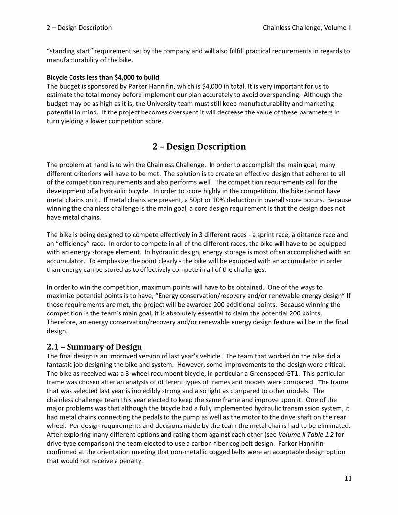
2.2 – Detailed Description Overview It is important to understand the overall workings of the bicycle before delving into the individual parts and their respective inner workings. Overall, the bicycle is designed so that the method of transferring power from the pedals to the drive wheel is done by fluid power. The transmission of power in a standard bicycle is shown in Figure 2.1. The transmission of power in a hydraulic bicycle that adheres to the requirements set by Parker Hannifin is shown in Figure 2.2.
Figure 2.1 – Standard bicycle power transmission
2 – Design Description Chainless Challenge, Volume II
13
Figure 2.2 – Hydraulic bicycle power transmission
After a conceptual understanding of the bike’s design is completed, a deeper dive into the inner workings can occur. Frame The frame selection was obvious. The team that worked on the bike last year had done extensive research on different bikes and frames and decided on a GreenSpeed GT1 recumbent frame. Having a recumbent bicycle has many advantages. First, the 3 wheel design provides instant stability and symmetry. Second, a recumbent frame has a wider wheel base than a standard 2 wheel bike and allows more room for mounting and integration of the hydraulic assembly. Finally, this frame in particular is a low-weight high strength option - this is critical for the proper use of the bike because it will be so heavily modified. The bike has to be able to withstand modifications and still be strong and able to withstand operative use. After exploring various options it was decided to use the existing frame. This also cuts back significantly on the direct costs as the frame alone costs $1900 (See Bill of Materials in section X.X.)
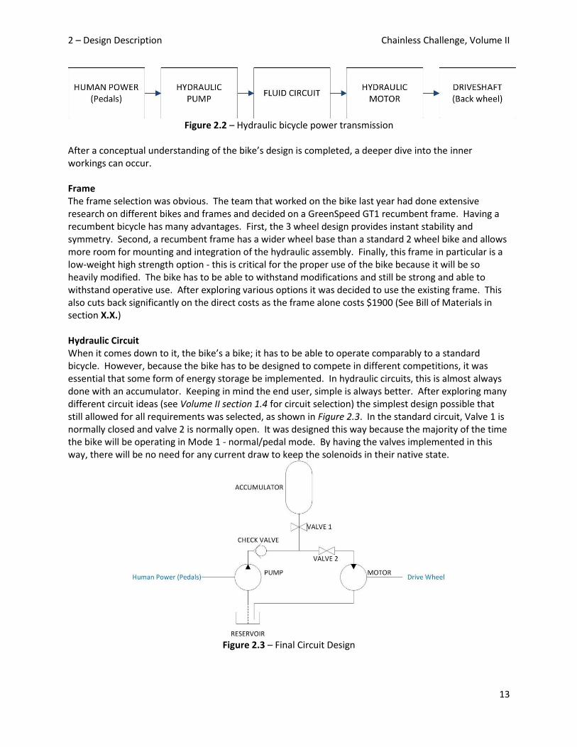
Hydraulic Circuit When it comes down to it, the bike’s a bike; it has to be able to operate comparably to a standard bicycle. However, because the bike has to be designed to compete in different competitions, it was essential that some form of energy storage be implemented. In hydraulic circuits, this is almost always done with an accumulator. Keeping in mind the end user, simple is always better. After exploring many different circuit ideas (see Volume II section 1.4 for circuit selection) the simplest design possible that still allowed for all requirements was selected, as shown in Figure 2.3. In the standard circuit, Valve 1 is normally closed and valve 2 is normally open. It was designed this way because the majority of the time the bike will be operating in Mode 1 - normal/pedal mode. By having the valves implemented in this way, there will be no need for any current draw to keep the solenoids in their native state.
Figure 2.3 – Final Circuit Design
2 – Design Description Chainless Challenge, Volume II
14
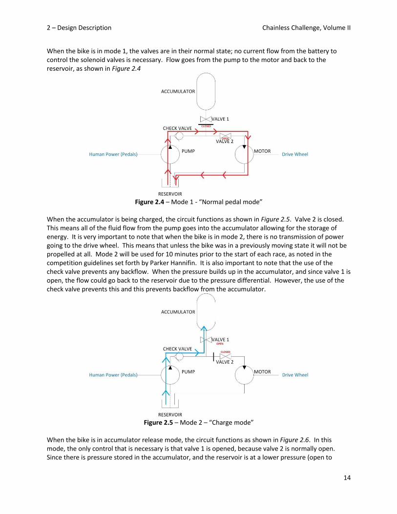
When the bike is in mode 1, the valves are in their normal state; no current flow from the battery to control the solenoid valves is necessary. Flow goes from the pump to the motor and back to the reservoir, as shown in Figure 2.4
Figure 2.4 – Mode 1 - “Normal pedal mode”
When the accumulator is being charged, the circuit functions as shown in Figure 2.5. Valve 2 is closed. This means all of the fluid flow from the pump goes into the accumulator allowing for the storage of energy. It is very important to note that when the bike is in mode 2, there is no transmission of power going to the drive wheel. This means that unless the bike was in a previously moving state it will not be propelled at all. Mode 2 will be used for 10 minutes prior to the start of each race, as noted in the competition guidelines set forth by Parker Hannifin. It is also important to note that the use of the check valve prevents any backflow. When the pressure builds up in the accumulator, and since valve 1 is open, the flow could go back to the reservoir due to the pressure differential. However, the use of the check valve prevents this and this prevents backflow from the accumulator.
Figure 2.5 – Mode 2 – “Charge mode”
When the bike is in accumulator release mode, the circuit functions as shown in Figure 2.6. In this mode, the only control that is necessary is that valve 1 is opened, because valve 2 is normally open. Since there is pressure stored in the accumulator, and the reservoir is at a lower pressure (open to

2 – Design Description Chainless Challenge, Volume II
15
atmospheric conditions) flow will go from the accumulator through the motor into the reservoir. This enables the bike to be propelled using the stored energy. It is also very important to note that the check valve once again prevents backflow through the pump. Another very important item to note is that it is still possible to pedal while in mode 3. The only issue is that if the pressure is too high, then the rider won’t be able to pedal. This is not a big problem during race 3, the efficiency race, since the rider isn’t allowed to pedal. It would only be advantageous to simultaneously pedal while in mode 3 during races 1 and 2, the sprint and distance races, respectively.
Figure 2.6 – Mode 3 – “Release mode”
Drive System The drive system on the bike answers the following question - how does one effectively and efficiently follow the block diagram (figure X.X) to transmit the human power to the drive wheel. Many different options were considered (see section X.X) for different ways to transfer the power to the back wheel. After a careful analysis it was decided that the best way to transmit the power is through the use of a cogged belt design. A cogged belt functions very similarly to a metal chain, as seen in a typical bike, but it is made up of a different material. A cogged belt is also wider than a chain and therefore requires a wider gear with a different set of “teeth” than a typical gear system. By utilizing a cogged belt design, power is effectively able to be transmitted with minimal losses and the implementation is greatly simplified - as opposed to the other design options. Pump/Motor When the bike was received from last year’s team, both the pump and motor were set to be 5cc fixed displacement pumps. This means for every 1 revolution of the pump/motor, 5 cubic centimeters of fluid are displaced. Having a fixed displacement pump has some major advantages over variable displacement pumps, though variable displacement pumps were carefully considered. The main advantages of having fixed displacement pumps are their overall efficiency and lack of need for control. If a variable displacement were implemented, the control system would become a lot more complicated. One of the overall considerations when designing this project is the end user. The system has to be designed to be as simple as possible for them. By having a design that works well and is simple the end result will be the best. After a detailed analysis occurred, it was elected to keep and use the same fixed displacement pump and motor from last year.

2 – Design Description Chainless Challenge, Volume II
16
Accumulator When the bike was received from last year’s team, they had a 1 gallon 3000 psi accumulator. A hydraulic accumulator is essentially a place to store potential energy. There are different types of accumulators, mainly a “spring” design or a “bladder” design. A spring design works by using fluid that is pushed into the accumulator to compress a spring which, in turn, creates potential stored energy. A bladder design uses fluid that is pushed into the accumulator to compress a balloon filled with gas (typically diatomic Nitrogen) as the means to store energy. Accumulators have to be effectively controlled for when to let fluid in (store energy) and when to let fluid out (release energy). In last year’s competition, the University of Minnesota’s team went almost 100 meters farther than all of the other teams and got 1st place in the competition. Because distance is a major factor the efficiency challenge, and since 10 full minutes are allowed prior to each race to charge the bike, it wasn’t even considered to go any smaller for the accumulator. However, any larger size of an accumulator would add more weight and complicate mountings. As a result of these analyses, it was decided to use the same 1-gallon 3000 psi accumulator as last year. Solenoids The way the hydraulic circuit is designed, some valves will have to open or close at a given time, depending on what the driver is trying to do. The best way to accomplish this is through the use of solenoid valves. Solenoid valves are essentially valves that are controlled via an electric circuit. While it is possible to implement manual valves, they are impractical and would add a lot of complication to the design. Solenoids are able to open or close with a minimal time delay, on the order of milliseconds in fact. Furthermore, the selected solenoids (Series DS162 - two-way) are designed to draw minimum current. Even though they are technically designed to be used by a 12V battery, a 6V battery will still provide enough current to operate the solenoids, but the battery may need to be replaced or charged for long durations. This was confirmed by the design that last year’s team used. Battery As discussed in the solenoids section, either a 6V or 12V battery will work. Depending on final assembly and space requirements/allowance, a final decision will be made. Electronic Controls Because the bike is equipped with electrically controlled solenoid valves, there has to be an electrical system integrated to control the valves. In Figure 2.7 the entire control circuit is shown. Essentially, the circuit works like this. When the “on switch” is set to be on, LED 3 lights up indicating the system is live and the bike is ready to go. It is important to note that even if the electrical system completely fails the bike will still work in a normal pedal operation mode, due to the intelligent design of the valves and hydraulic circuit. When control switch 1 is pressed, valve 2 close and valve 1 opens. This is done in the coding of the arduino. When it detects that the “charge” button is pressed, it sends a signal to the base of the TIP 120 Transistors - allowing the solenoid to draw its current from the 6/12V battery. The reason a transistor has to be used is because the Arduino itself doesn’t have enough power to control the solenoids, and hooking a battery up directly to the board would fry the unit. Control switch 1 sets the bike into charge mode and the LED indicating the bike is charging is then lit up. Likewise, when control switch 2 is pressed, valve 1 and 2 are both set to open. This allows discharging from the accumulator. The LED indicating the bike is discharging is then lit up. One very important consideration for the controls is that if both buttons are pressed at the same time, the bike defaults to “charge” mode - this is to prevent involuntary discharging of the accumulator. It is also possible that a red “error” LED will be implemented into the design if needed.

2 – Design Description Chainless Challenge, Volume II
17
Figure 2.7 – Electronic Circuit
Solar Panels Solar panels essentially work by converting light energy into direct electrical energy. By adding a solar panel to the bike, it will be possible to charge the battery passively. The electrical control system is critical to the motive power of the bike for competitions. The solar panel will likely be mounted on the back of the bike on top of the rack that contains the electrical control system block. It will also be designed with a simple “on/off” manual connector. The reason for this is because the battery cannot simultaneously charge and discharge. This means when the bicycle is “on”, the solar connections have to be disconnected otherwise major electrical problems could occur. Furthermore, there will be a status LED to indicate when the battery is charging. Even though this will take a small amount of current from the solar panel to light up the LED it is important that any user of the bike knows exactly what is going on in terms of the systems on the bike. A fallback plan will also be implemented - if the solar charging system is “active” and the bike is turned on - an error LED will likely light up and an audible error tone will sound. All of these design requirements will be taken into consideration when actually implementing the solar system - there are strong chances that heavy modifications will occur. The reasoning for this is that the solar panel implementation will likely be done in the spring 2013 semester for the follow-up finishing team and may not be done during the fall 2012 semester. Functional Block Diagram A high-level overview of the design specifications/requirements is provided below in Figure 2.8 In the competition criteria, Parker Hannifin has stated that the bicycle must be driven by a fluid power transmission, the bicycle must be able to perform all three race events, and it must be able to transported and operated by a single human [2]. All of these criteria have been incorporated into each of the three broad functions provided in the figure below.

2 – Design Description Chainless Challenge, Volume II
18
Figure 2.8 – Functional block diagram
Functional Description Referencing the functional block diagram, a more detailed description of each function is provided below. Human Input The bicycle last year’s U of M team competed with was a bicycle that had two metal chains. One chain was used to transmit the pedaling power of the operator to the hydraulic pump that operated the fluid circuit. The second chain was used to transmit the power from the hydraulic motor to the drive wheel. This year, however, there are bonus points awarded to teams who develop a bicycle that is completely chainless. Therefore, in order to remove these two chains, alternative methods of transmitting these loads were brainstormed. These methods were discussed in the Concept Alternatives section of Volume II of this report. A detailed description of the concept selection is also provided in that section. Ultimately, cogged belts were determined to be the best option for replacing the metal chains. Cogged Belts Cogged belts are used as an alternative to a metal chain transmission - they work in much the same way. Cogged belts are usually made out of a high tensile strength rubber, with a steel braiding that run through the inside of the belt for additional strength. The teeth of the belt are molded directly to the belt’s surface. Refer to Figure 2.9 for an illustration.
Figure 2.9 – Cogged belt [X - (http://www.vbeltindia.com/Cut_Edge_Moulded_Cogged_Belts.html)
Power Transmission Per the Chainless Challenge competition criteria, in order to be eligible to compete, the bicycle must be completely driven by fluid power. In this case, hydraulics were chosen for the many reasons discussed earlier in this report. Additionally, as described earlier in section 4.2 of this report, a hydraulic circuit was designed, and components were selected.

2 – Design Description Chainless Challenge, Volume II
19
New to this year’s competition are bonus points that are awarded to teams who incorporate some sort of energy regeneration/recovery system into the bicycle design. Therefore, possible solutions were brainstormed and ranked against each other based on the following criteria: Added weight, labor intensity and added energy. Added Weight The amount of additional weight that each of the three brainstormed solutions would add to the system was a very important criterion. Any additional weight would negatively impact the performance of the bicycle in all three races. Therefore, it is essential to design the bicycle to be as light as possible. Labor Intensity Labor intensity is also a concern which revolves around the strict deadline of the Senior Design show. An estimate of the amount of time it would take the team to design and implement each system had to be considered for this reason. Added Energy Lastly, the amount of potential energy that could be generated and added to the system in order to be used later had to be estimated and compared against that of all potential solutions. For a summary of the solution matrix results, refer to Table 2.1.
Table 2.1 – Regeneration / Recovery solution matrix
Output In order to measure the output of the system, the performance in all three race events, as well as the ability for a single human to transport and operate the bicycle had to be considered. Performance in all Three Events The fact that there are three separate events in the competition meant that the bicycle had to be designed with the performance in all events being considered. In other words, designing the bicycle to perform well in just one competition would likely have a negative effect on the bike’s performance in the others. Therefore, the following items all had to be considered with the three races in mind: accumulator, frame, hydraulic circuit, motor/pump and the fittings/hoses Single Human Transportation The ability for the bicycle to be transported and operated by a single human is not only critical to the performance of the bicycle in all three of the race events, but also in the manufacturability design criteria as well. In order to ensure that a single human could operate the bicycle, the hydraulic circuit and components were all designed around the theoretical input torque that a human could provide to the hydraulic pump.

2 – Design Description Chainless Challenge, Volume II
20
Overview Drawing For the three functions that have been described above - human input, transmission, and output – Figure 2.10 has been provided to demonstrate how each function works together.
Figure 2.10 – Simplified functional overview
Human Input As a human inputs torque to the pedals, that load is transmitted to the hydraulic pump via the cogged belt. Power Transmission From here, the pump pushes hydraulic fluid through the circuit and into the motor. Output Lastly, as fluid is pushed into the motor, the motor rotates, and power is transmitted again through the cogged belt to the drive wheel which causes forward motion. Of course, there are some more elaborate intricacies involved with different operation modes, however the figure above is meant to provide a simplified view of how the bicycle actually operates.
2.3 – Additional Uses The hydraulic bicycle as described above could be used and improved upon by future Chainless Challenge senior design teams. Further analysis of the hydraulic fluid lines could be performed in order to determine if the lines could be even further shortened and/or optimized by re-positioning them for use with fewer fittings. Doing so would increase the overall efficiency of the bicycle as these fittings incorporate losses into the system as a whole. Additionally, a hydraulic braking system could be analyzed further in an attempt to justify its use. This type of analysis was performed throughout the concept generation stage of the design process for this project; however it was ultimately deemed that the added benefit of such a system was not enough to overcome its drawbacks. In terms of alternative uses of the hydraulic system that has been design for this project, it could be used for any other type of human powered hydraulic bicycle, or even for other low-speed motorized vehicle. Additionally, small alterations could be made to the design to allow for higher pressures and loads in order for it to be used in larger systems such as those within the power-sports market. With

3 – Evaluation Chainless Challenge, Volume II
21
further analysis, hydraulic transmissions could possibly be competitive alternatives in vehicles such as all-terrain-vehicles, side-by-side vehicles, motorcycles, and even jet-skis.
3 – Evaluation The solution presented above was tested based five difference design criteria which were established in
the design requirements section of this report. For an overview of these tests, refer to sections below.
For more detail, please refer to the evaluation section of Volume II.
3.1 – Evaluation Plan The main design requirements for the project were outlined in the Problem Definition section. The main five criterions to be directly tested and evaluated are as follows:
Chainless design Ability to finish all races Utilization of renewable/recoverable energy design Bicycle costs less than $4,000 to build Single rider system design
Chainless design The chainless design is a binary requirement - that is to say, the bike either has metal chains or it does not. It is clear from the concept selection process that the end design does not have metal chains and this requirement is met. The replacement was a non-metallic cogged belt design that was approved by Parker Hannifin at the orientation meeting. Ability to finish all races The ability to finish all races is an essential requirement for the project. If the bicycle isn’t able to compete in all of the races, then it was not designed properly. Since the actual competition for the bike isn’t until April of 2013, this ability will be evaluated during a thorough benchmarking and testing of the bike once it is completed. Utilization of renewable/recoverable energy design The utilization of renewable/recoverable energy design was one of the tougher requirements to hit. Being that there were many different design options, it was tough to come up with one that fulfilled this requirement and worked effectively. Since the guidelines for this were laid out by Parker Hannifin in the competition specifications, a direct comparison between the end design and the requirements will be made to make sure the requirement is met. Bicycle costs less than $4000 to build For analyzing the budget of the bicycle, it is simple to say either yes, the bike falls within the specified budget, or no, the bike falls outside of the specified budget. This evaluation was made with a direct comparison to the bill of materials, and can be found in (Volume II section 2.1). Based off this bill of materials, the bicycle cost this year’s team a total of $1679.39 to build. Single rider system design The single rider system design is another simple requirement to evaluate. Either the bike can be powered by a single person, or it can’t. The design that has been presented throughout this report is in fact operable by a single rider, thus fulfilling this design test.
3 – Evaluation Chainless Challenge, Volume II
22
3.2 – Evaluation Results For the results of each test, as described above, an abstract has been prepared. Please reference the sections below for an overview of the results of each test. More detail is provided in the evaluation section of Volume II. Chainless Design/Less than $4000 dollars These evaluations do not require any type of analytical evaluation or testing. The requirements are either met or are not met. Clearly, the chainless design requirement has been met as the bike is assembled without metallic chains. The budget requirements are also met, as shown in (Volume II section 2.1). Ability to finish all races The bicycle needs to be able to effectively compete in 3 different races: a sprint race, a long distance race, and an energy efficiency race. Instead of doing theoretical calculations to evaluate the ability of the bicycle to compete in all of the races, it was decided that physical testing and benchmarking of the bike is a better approach because winning the competition is of highest priority. Three tests will be performed all of which fall under the category of ability to finish all races. The results of these tests, however, are still dependent upon a variety of factors, and the analysis will likely be performed during the spring semester as the overall performance of the vehicle is optimized prior to the competition. If there is something that needs to be changed, there will be adequate time in the spring semester to make these changes before the competition in April of 2013. Accumulator charging/discharge rate This test will directly emulate charging the bicycle at the competition. As laid out in the competition guidelines, 10 minutes will be allowed prior to each race to charge the accumulator. At least 3 different trials will be held with different riders charging the accumulator for a duration of up to 10 minutes, taking note of the pressure at given time intervals. This will allow for a graphical analysis, and provide an idea of the pressure developed as a function of time. With a mathematical model derived from experimental data, further analysis can be developed. For each trial, after the accumulator has been charged, benchmarking will be done to calculate the discharge rate of the bicycle and acceleration developed in the bicycle. Pressure measurements left in the system will also be taken in order to establish a relationship between bicycle speed and distance traveled. Distance Test This test will emulate the distance race of the competition. Pending allotted time and space, the bicycle will be driven around campus at the University of Minnesota -trying to always stay on a flat surface and avoid hills (to simulate the competition grounds). This test will be more of a qualitative test on how the bike feels and works overall.
Sprint Test This test will emulate the sprint race of the competition. This will be done with both a simultaneous discharging and pedaling of the bike. The main reasons for this test are to see if there is an optimum process by which to obtain maximum velocity as quick as possible. Because the bicycle is equipped with an internal gear hub in the rear, the test will be implemented many times starting in different gears to determine an optimum starting gear. Additionally, any type of conclusions that come from the “right time” to discharge and the best way to do so will be optimized. It is certainly possible that an accurate enough mathematical model could be combined with gearing ratio data to create an automated
3 – Evaluation Chainless Challenge, Volume II
23
sequence by which to discharge the accumulator at given time intervals through motion control techniques. However, as with the previous tests, the results of this test are still dependent upon a variety of factors, and the analysis will likely be performed during the spring semester as the overall performance of the vehicle is optimized prior to the competition.
Utilization of renewable/recoverable energy design This particular requirement is also more binary in nature, either yes, the design meets the requirement, or no, the design does not meet the requirement. However, the quality by which the requirement is met can be analyzed directly. The design uses 2 6V batteries in series, to get a total difference of 12 potential volts. Each battery is 4300mAH. There are 2 solar panels which each have a power output of .63W for a total output of 1.26W from the solar panels. During the testing process of charging and discharging the accumulator, the solenoids will need to be in their non-normal state. This means current will have to be drawn from the batteries. Benchmarking will be done to calculate the life left in the batteries as a function of time. This will be compared to the theoretical charging rates of the batteries under optimal and non-optimal solar conditions. Like the other tests, this cannot be done until the design is complete, so only the theory and plan behind the test can be documented in this report. Single rider system design The bicycle presented is able to be powered by a single human. In order for a single rider to operate the bicycle, optimal gearing ratios and selections were made in order to ensure that a single user could supply ample torque to the system to allow the bicycle to move forward. See Volume II Table 3.1 for a torque analysis.
3.3 – Discussion With the results of the binary tests in mind, and from making engineering approximations on the results of the tests which will be performed during the spring semester, the following strengths and weaknesses of the final design, as well as a description of the next steps were formulated. Refer below for more information in these areas. Strengths & Weaknesses The strengths of the final design are definitely the internal gear-hub, and the solar energy recovery
system. During the mid-project review meeting with Parker-Hannifin, the solar recovery system was
presented. The representatives from Parker were very impressed with the innovations that were being
made in this area of the competition, and the team’s creativity in the way that this competition criterion
was interpreted. The Parker reps also mentioned that no other team in the country had been this
creative and no other team was implementing such a recovery system. Additionally, the use of the
internal gear is what allows the use of a belt drive system in the first place. By enabling the rear wheel
to operate with a one-way clutch, the way in which normal bicycle drive wheels operate make the belt
drive system possible. Without this, other drive systems would have been needed to be explored and
implemented. This selection significantly reduced the complexity of the drive system.

3 – Evaluation Chainless Challenge, Volume II
24
Next Steps From here, now that the bicycle was been designed, fabricated, and assembled, the quantitative testing
can begin. This testing will take place during the spring semester and the bicycle design is being
optimized for the competition which occurs in April 2013. Improvements could be made in the hydraulic
circuit by exploring ways to reduce the amount of hosing required, and by removing some of the 90
degree, and other angled fittings. One possible solution which has been discussed with the team’s
project supervisor and representative from Parker is by inserting a hydraulic manifold into the circuit.
This would significantly reduce the amount of hose fittings needed, and reduce the amount of efficiency
losses associated with these hoses.