Parity-Time Symmetric Coupled Microresonators with … · Parity-Time Symmetric Coupled...
17
arXiv:1501.07455v1 [physics.optics] 29 Jan 2015 Parity-Time Symmetric Coupled Microresonators with a Dispersive Gain/Loss Sendy Phang 1,∗ , Ana Vukovic 1 , Stephen Creagh 2 , Trevor M. Benson 1 , Phillip D. Sewell 1 , Gabriele Gradoni 2 1 George Green Institute for Electromagnetics Research, Faculty of Engineering, University of Nottingham,Nottingham, NG7 2RD, UK 2 School of Mathematical Sciences, University of Nottingham, Nottingham. NG7 2RD, UK ∗ [email protected] Abstract: The paper reports on the coupling of Parity-Time (PT)- symmetric whispering gallery resonators with realistic material and gain/loss models. Response of the PT system is analyzed for the case of low and high material and gain dispersion, and also for two practical scenarios when the pump frequency is not aligned with the resonant frequency of the desired whispering gallery mode and when there is imbalance in the gain/loss profile. The results show that the presence of dispersion and frequency misalignment causes skewness in frequency bifurcation and significant reduction of the PT breaking point, respectively. Finally, as coupled WGM resonators are inherently lossy structures, we show that unbalancing the gain/loss in resonators is required to compensate for inherent loss of the structure and achieve improved PT properties. © 2018 Optical Society of America OCIS codes: (080.6755) Systems with special symmetry;(140.3945) Microcavities; (230.4555) Coupled resonators References and links 1. C. M. Bender, S. Boettcher, and P. N. Meisinger, “PT–symmetric quantum mechanics,” J. Math. Phys. 40, 2201 (1999). 2. Z. Lin, H. Ramezani, T. Eichelkraut, T. Kottos, H. Cao, and D. N. Christodoulides, ”Unidirectional invisibility induced by PT–iymmetric periodic structures,” Phys. Rev. Lett. 106, 213901 (2011). 3. Y. D. Chong, L. Ge, and A. D. Stone, “PT–Symmetry breaking and laser-absorber modes in optical scattering systems,” Phys. Rev. Lett. 106, 093902 (2011). 4. H. Benisty, C. Yan, A. Degiron, and A. Lupu, “Healing near-PT-symmetric structures to restore their character- istic singularities: analysis and examples,” J. Light. Technol. 30, 2675–2683 (2012). 5. A. Lupu, H. Benisty, and A. Degiron, “Switching using PT symmetry in plasmonic systems: positive role of the losses,” Opt. Express 21, 192–195 (2013). 6. F. Nazari, M. Nazari, and M. K. Moravvej-Farshi, “A 2 × 2 spatial optical switch based on PT–symmetry.,” Opt. Lett. 36, 4368–4370 (2011). 7. H. Hodaei, M.-A. Miri, M. Heinrich, D. N. Christodoulides, and M. Khajavikhan, “PT symmetric large area single mode DFB lasers,” in CLEO: 2014 (OSA, 2014), Vol. 1, p. FM1D.3. 8. S. Longhi and L. Feng, “PT-symmetric microring laser-absorber.,” Opt. Lett. 39, 5026–5029 (2014). 9. S. Phang, A. Vukovic, H. Susanto, T. M. Benson, and P. Sewell, “Ultrafast optical switching using parity–time symmetric Bragg gratings,” J. Opt. Soc. Am. B 30, 2984–2991 (2013). 10. S. Phang, A. Vukovic, T. M. Benson, H. Susanto, and P. Sewell, “A versatile all–optical parity–time signal processing device using a Bragg grating induced using positive and negative Kerr-nonlinearity,” Opt. Quantum Electron. 47, 37–47 (2015).
Transcript of Parity-Time Symmetric Coupled Microresonators with … · Parity-Time Symmetric Coupled...
arX
iv:1
501.
0745
5v1
[phy
sics
.opt
ics]
29
Jan
2015
Parity-Time Symmetric CoupledMicroresonators with a Dispersive
Gain/Loss
Sendy Phang1,∗, Ana Vukovic1, Stephen Creagh2, Trevor M. Benson1,Phillip D. Sewell1, Gabriele Gradoni2
1George Green Institute for Electromagnetics Research, Faculty of Engineering,University of Nottingham,Nottingham, NG7 2RD, UK
2School of Mathematical Sciences, University of Nottingham,Nottingham. NG7 2RD, UK
Abstract: The paper reports on the coupling of Parity-Time (PT)-symmetric whispering gallery resonators with realistic material andgain/loss models. Response of the PT system is analyzed for the case of lowand high material and gain dispersion, and also for two practical scenarioswhen the pump frequency is not aligned with the resonant frequency ofthe desired whispering gallery mode and when there is imbalance in thegain/loss profile. The results show that the presence of dispersion andfrequency misalignment causes skewness in frequency bifurcation andsignificant reduction of the PT breaking point, respectively. Finally, ascoupled WGM resonators are inherently lossy structures, weshow thatunbalancing the gain/loss in resonators is required to compensate forinherent loss of the structure and achieve improved PT properties.
© 2018 Optical Society of America
OCIS codes: (080.6755) Systems with special symmetry;(140.3945) Microcavities;(230.4555) Coupled resonators
References and links1. C. M. Bender, S. Boettcher, and P. N. Meisinger, “PT–symmetric quantum mechanics,” J. Math. Phys.40, 2201
(1999).2. Z. Lin, H. Ramezani, T. Eichelkraut, T. Kottos, H. Cao, andD. N. Christodoulides, ”Unidirectional invisibility
induced by PT–iymmetric periodic structures,” Phys. Rev. Lett.106, 213901 (2011).3. Y. D. Chong, L. Ge, and A. D. Stone, “PT–Symmetry breaking and laser-absorber modes in optical scattering
systems,” Phys. Rev. Lett.106, 093902 (2011).4. H. Benisty, C. Yan, A. Degiron, and A. Lupu, “Healing near-PT-symmetric structures to restore their character-
istic singularities: analysis and examples,” J. Light. Technol. 30, 2675–2683 (2012).5. A. Lupu, H. Benisty, and A. Degiron, “Switching using PT symmetry in plasmonic systems: positive role of the
losses,” Opt. Express21, 192–195 (2013).6. F. Nazari, M. Nazari, and M. K. Moravvej-Farshi, “A 2×2 spatial optical switch based on PT–symmetry.,” Opt.
Lett. 36, 4368–4370 (2011).7. H. Hodaei, M.-A. Miri, M. Heinrich, D. N. Christodoulides, and M. Khajavikhan, “PT symmetric large area
single mode DFB lasers,” inCLEO: 2014 (OSA, 2014), Vol. 1, p. FM1D.3.8. S. Longhi and L. Feng, “PT-symmetric microring laser-absorber.,” Opt. Lett.39, 5026–5029 (2014).9. S. Phang, A. Vukovic, H. Susanto, T. M. Benson, and P. Sewell, “Ultrafast optical switching using parity–time
symmetric Bragg gratings,” J. Opt. Soc. Am. B30, 2984–2991 (2013).10. S. Phang, A. Vukovic, T. M. Benson, H. Susanto, and P. Sewell, “A versatile all–optical parity–time signal
processing device using a Bragg grating induced using positive and negative Kerr-nonlinearity,” Opt. QuantumElectron.47, 37–47 (2015).
11. M. Kulishov, B. Kress, and R. Slavk, “Resonant cavities based on Parity-Time-symmetric diffractive gratings,”Opt. Express21, 68–70 (2013).
12. H. F. Jones, “Analytic results for a PT -symmetric optical structure,” J. Phys. A Math. Theor.45, 135306 (2012).13. J.Ctyroky, V. Kuzmiak, and S. Eyderman, “Waveguide structures with antisymmetric gain/loss profile,” Opt.
Express18, 21585–21593 (2010).14. J.Ctyroky, “Dispersion properties of coupled waveguides with loss and gain: a full-vectorial analysis,” Opt.
Quantum Electron.46, 465–475 (2014).15. R. El-Ganainy, K. G. Makris, D. N. Christodoulides, and Z. H. Musslimani, “Theory of coupled optical PT-
symmetric structures,” Opt. Lett.32, 2632–2634 (2007).16. M. Greenberg and M. Orenstein, “Unidirectional complexgrating assisted couplers.,” Opt. Express12, 4013–
4018 (2004).17. S. Longhi, “PT-symmetric laser absorber,” Phys. Rev. A82, 031801 (2010).18. H. Nolting, G. Sztefka, and J.Ctyroky, “Wave propagation in a waveguide with a balance ofgain and loss,” in
Integrated Photonics Research (OSA, 1996), pp. 76–80.19. S. Phang, A. Vukovic, H. Susanto, T. M. Benson, and P. Sewell, “Impact of dispersive and saturable gain/loss on
bistability of nonlinear parity-time Bragg gratings.,” Opt. Lett. 39, 2603–2606 (2014).20. C. E. Ruter, K. G. Makris, R. El-Ganainy, D. N. Christodoulides, M. Segev, and D. Kip, “Observation of parity-
time symmetry in optics,” Nat. Phys.6, 192–195 (2010).21. B. Peng, S. K.Ozdemir, F. Lei, F. Monifi, M. Gianfreda, G. L. Long, S. Fan, F.Nori, C. M. Bender, and L. Yang,
“Paritytime-symmetric whispering-gallery microcavities,” Nat. Phys.10, 1–5 (2014).22. B. Peng, S. K.Ozdemir, S. Rotter, H. Yilmaz, M. Liertzer, F. Monifi, C. M. Bender, F. Nori, and L. Yang,
“Loss-induced suppression and revival of lasing.,” Science, 346, no. 6207, pp. 328–332, (2014).23. A. Regensburger, M. Miri, and C. Bersch, “Observation ofdefect states in PT-symmetric optical lattices,” Phys.
Rev. Lett.110, 223902, (2013).24. L. Chang, X. Jiang, S. Hua, C. Yang, J. Wen, L. Jiang, G. Li,G. Wang, and M. Xiao, “Parity–time symmetry and
variable optical isolation in active-passive-coupled microresonators,” Nat. Photonics8, 524–529 (2014).25. L. Feng, Z. J. Wong, R.-M. Ma, Y. Wang, and X. Zhang, “Single-mode laser by parity-time symmetry breaking,”
Science346, 972–975 (2014).26. S. Phang, A. Vukovic, H. Susanto, T. M. Benson, and P. Sewell, “Practical limitation on operation of nonlinear
parity-time Bragg gratings,” inMETA 2014 Conference (2014), pp. 270–275.27. S. C. Creagh and M. D. Finn, “Evanescent coupling betweendiscs: a model for near-integrable tunnelling,” J.
Phys. A. Math. Gen.34, 3791–3801 (2001).28. J. Paul, C. Christopoulos, and D. W. P. Thomas, “Generalized material models in TLM .I. Materials with
frequency-dependent properties,” IEEE Trans. Antennas Propag.47, 1528–1534 (1999).29. C. Christopoulos,The Transmission-Line Modeling Method TLM (IEEE Press, 1995).30. L. D. Landau, J. S. Bell, M. J. Kearsley, L. P. Pitaevskii,E. M. Lifshitz, and J. B. Sykes,Electrodynamics of
Continuous Media, 2nd ed. (Elsevier, 1984)31. A. A. Zyablovsky, A. P. Vinogradov, A. V. Dorofeenko, A. A. Pukhov, and A. A. Lisyansky, “Causality and phase
transitions in PT-symmetric optical systems,” Phys. Rev. A89, 033808 (2014).32. S. C. Hagness, R. M. Joseph, and A. Taflove, “Subpicosecond electrodynamics of distributed Bragg reflector
microlasers: Results from finite difference time domain simulations,” Radio Sci.31, 931–941 (1996).33. S. V. Boriskina, “Spectrally engineered photonic molecules as optical sensors with enhanced sensitivity: a pro-
posal and numerical analysis,” J. Opt. Soc. Am. B23, 1565–1573 (2006).34. E. I. Smotrova and A. I. Nosich, “Optical coupling of an active microdisk to a passive one: effect on the lasing
thresholds of the whispering-gallery supermodes.,” Opt. Lett.38, 2059–2061 (2013).35. E. Smotrova, A. Nosich, T. M. Benson, and P. Sewell, “Optical coupling of whispering-gallery modes of two
identical microdisks and its effect on photonic molecule lasing,” IEEE J. Sel. Top. Quantum Electron.12, 78–85(2006).
36. M. Abramowitz and I. A. Stegun,Handbook of Mathematical Functions (U.S. Department of Commerce, NIST,1972).
1. Introduction
Photonics is emerging as a popular practical platform for the exploration of Parity-Time (PT)-symmetric systems characterized by balanced loss and gain and having a threshold point atwhich real eigenfrequencies of the system coalesce to become complex conjugates [1–4]. Theexistence of this threshold point is essential to the uniqueproperties of PT-structures, such asunidirectional invisibility and simultaneous lasing and absorption [2,3]. This phenomena opensnew avenues for the realization of practical devices such aslasers, optical memory, opticalswitches and logic-gates [5–11]. To date, PT-symmetric structures based on Bragg gratings and
coupled optical systems have been investigated both theoretically [2–4, 8, 12–19] and exper-imentally [20–25]. Recently, a PT-symmetric system based on two coupled microresonatorsand two fiber-taper waveguides has been experimentally demonstrated and shown to exhibitdirection-dependent behavior at a record low power of 1µW [21, 25]. This is primarily at-tributed to strong field localization and build up of energy in the resonant whispering gallerymodes [21, 25], and has further strengthened the argument for using resonant structures ratherthan waveguides as building blocks of PT-symmetric systems. In contrast to PT symmetric cou-pled waveguide systems where the eigenmodes are purely realbelow the threshold point, the PTsymmetric coupled microresonators have complex eigenfrequencies below the threshold pointdue to inherent radiation losses [3,4,13,17].
In this paper we investigate the fundamental properties of the PT resonant system basedon two coupled whispering gallery resonators within the context of both realistic materialproperties and practical operating constraints. In particular we discuss how practical disper-sive properties of material gain and loss that satisfy the Kramers-Kronig relationship affect theperformance of microcavity-based PT resonant structures.Our surprising conclusion is that ac-counting for large, yet realistic, levels of dispersion preserves the essential threshold-behaviourpredicted by completely PT-symmetric dispersionless models, while more moderate levels ofdispersion can completely change the character of the response of the system to increasing gainand loss. In particular, when there is moderate dispersion the gain and loss materials responddifferently to frequency shifts in such a way that sharp threshold points give way to gradualchanges over a range of parameters. When dispersion is increased further, the response revertsto threshold behaviour of the type seen in non-dispersive PT-symmetric systems, albeit withsome breaking of detailed quantitative symmetry.
Our recent work on dispersive PT-Bragg gratings has shown that material dispersion limitsthe unidirectional invisibility to a single frequency which is in stark contrast to previous resultsthat assumed idealized gain/loss profile in order to demonstrate wideband unidirectional behav-ior [19, 26]. In this paper, the performance of the microresonator-based PT system is analyzedfor practical scenarios involving: a) frequency mismatch between the cavity resonant frequencyand the gain pump frequency and, b) imperfect balance of the gain and loss in the system. Theanalysis of the microresonator-based PT system is achievedusing an exact representation ofthe problem based on boundary integral equations and explicit analytical results are given for aweakly coupled system using perturbation analysis [27]. Weconcentrate on the weakly-coupledlimit in our detailed calculations because that captures the essential properties of the thresholdbehavior of the PT-symmetry while allowing simple analytical calculations to be used. Finally,real-time field evolution in a two microresonator PT-symmetric system is analyzed for differ-ent levels of dispersion using the numerical time domain Transmission Line Modelling (TLM)method [9,28,29].
2. PT symmetric coupled microresonators
In this section we describe the theoretical background of a PT-symmetric system based on twocoupled microresonators. The system, in which both microresonators have radiusa and are sep-arated by a gapg, is illustrated schematically in Fig. 1. The active and passive microresonatorshave complex refractive indicesnG andnL respectively, that are typically chosen to satisfy thePT conditionnG = n∗L, where * denotes complex conjugate,n = (n′+ jn′′), andn′ andn′′ rep-resent the real and imaginary parts of the refractive index.In practice, localized gain mightbe achieved by means of erbium doping and optical pumping of the active microresonator,while masking the lossy microresonator as in [20–22, 25]. Both resonators are assumed to besurrounded by air.
The refractive index of dispersive materials is frequency dependent but must also satisfy the
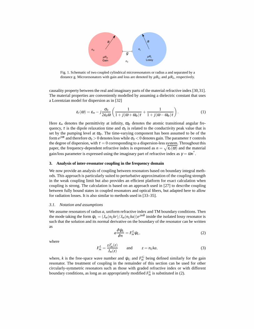
Fig. 1. Schematic of two coupled cylindrical microresonators or radius a and separated by adistance g. Microresonators with gain and loss are denoted by µRG andµRL, respectively.
causality property between the real and imaginary parts of the material refractive index [30,31].The material properties are conveniently modelled by assuming a dielectric constant that usesa Lorentzian model for dispersion as in [32]
εr(ω) = ε∞ − jσ0
2ε0ω
(
11+ j(ω +ωσ)τ
+1
1+ j(ω −ωσ )τ
)
. (1)
Here ε∞ denotes the permittivity at infinity,ωσ denotes the atomic transitional angular fre-quency,τ is the dipole relaxation time andσ0 is related to the conductivity peak value that isset by the pumping level atωσ . The time-varying component has been assumed to be of theforme jωt and thereforeσ0 > 0 denotes loss whileσ0 < 0 denotes gain. The parameterτ controlsthe degree of dispersion, withτ = 0 corresponding to a dispersion-less system. Throughout thispaper, the frequency-dependent refractive index is expressed asn =
√
εr(ω) and the materialgain/loss parameter is expressed using the imaginary part of refractive index asγ = ωn
′′.
3. Analysis of inter-resonator coupling in the frequency domain
We now provide an analysis of coupling between resonators based on boundary integral meth-ods. This approach is particularly suited to perturbative approximation of the coupling strengthin the weak coupling limit but also provides an efficient platform for exact calculation whencoupling is strong. The calculation is based on an approach used in [27] to describe couplingbetween fully bound states in coupled resonators and optical fibers, but adapted here to allowfor radiation losses. It is also similar to methods used in [33–35].
3.1. Notation and assumptions
We assume resonators of radiusa, uniform refractive index and TM boundary conditions. Thenthe mode taking the formψL = (Jm(nLkr)/Jm(nLka))e jmθ inside the isolated lossy resonator issuch that the solution and its normal derivative on the boundary of the resonator can be writtenas
a∂ψL
∂n= FL
mψL, (2)
where
FLm =
zJ′m(z)Jm(z)
and z = nLka, (3)
where,k is the free-space wave number andψG andFGm being defined similarly for the gain
resonator. The treatment of coupling in the remainder of this section can be used for othercircularly-symmetric resonators such as those with gradedrefractive index or with differentboundary conditions, as long as an appropriately modifiedFL
m is substituted in (2).
3.2. Exact solution using boundary-integral representation
An exact boundary integral representation of the coupled problem is conveniently achievedby applying Green’s identities to a regionΩ which excludes the resonators, along with aninfinitesimally small layer surrounding them (so that the boundariesBG andBL of the resonatorsthemselves lie just outsideΩ). In Ω, we assume that the refractive index takes the valuen0 = 1,so that the free-space Green’s function is
G0(x,x′) =−j4
H0(k|x− x′|), (4)
whereH0(z) = J0(z)− jY0(z) denotes the Hankel function of the second kind (and the solutionis assumed to have time dependence ejωt ). Then, applying Green’s identities to the regionΩand assuming radiating boundary conditions at infinity leads to the equation
0=
∫
BG+BL
(
G0(x,x′)
∂ψ(x′)∂n′
−∂G0(x,x′)
∂n′ψ(x′)
)
s.′ (5)
whenx lies on eitherBL or BG (and therefore just outside ofΩ).We now expand the solution on the respective resonator boundaries as Fourier series,
ψG = ∑m
αGm ejmθG and ψL = ∑
mαL
mejmθL , (6)
in the polar anglesθG andθL centered respectively on the gain and lossy resonators, runningin opposite senses in each resonator and zeroed on the line joining the two centers. The corre-sponding normal derivatives can be written
∂ψG
∂n= ∑
m
1a
FGm αG
m ejmθG and∂ψG
∂n= ∑
m
1a
FGm αG
m ejmθG . (7)
Using Graf’s theorem [36] to expand the Green’s functionG0(x,x′) analogously in polar coor-dinates on each boundary, the integral equation (5), evaluated separately forx onBL and onBG,leads to a pair of matrix equations
DGαG +CGLαL = 0
CLGαG +DLαL = 0. (8)
Here,
αG =
...αG
mαG
m+1...
and αL =
...αL
mαL
m+1...
(9)
are Fourier representations of the solution on the boundaries of the gain and lossy resonatorsrespectively. The matricesDG andDL are diagonal with entries
DG,Lmm = Jm(u)Hm(u)
(
FG,Lm −
uH ′m(u)
Hm(u)
)
, whereu = ka, (10)
and provide the solutions of the isolated resonators. The matricesCGL andCLG describe cou-pling between the resonators. The matrixCGL has entries of the form
CGLlm = Jl(u)Hl+m(w)Jm(u)
(
FLm −
uLJ′m(u)Jm(u)
)
, (11)
whereu = ka, w = kb andb is the center-center distance between the gain and lossy resonators.The matrixCLG is defined analogously by exchanging the labelsG andL.
3.3. PT-symmetry in the exact solution
The system (8) can be presented more symmetrically by using the scaled Fourier coefficients
αLm = Jm(u)
(
FLm −
uJ′m(u)Jm(u)
)
αLm (12)
(along with an analogous definition ofαGm ). Then (8) can be rewritten
DGαG + CαL = 0
CαG + DLαL = 0, (13)
where the diagonal matricesDG,L have entries
DG,Lmm =− j
Hm(u)FG,Lm − uH ′
m(u)
Jm(u)FG,Lm − uJ′m(u)
, whereu = ka, (14)
and the same (symmetric) matrixC, with entries
Clm =− jHl+m(w), (15)
couples solutions in both directions.We have included an overall factor of− j in these equations to emphasise an approximate PT-
symmetry that occurs whennG = n∗L. Then, in the limit of high-Q whispering gallery resonancesfor which we may approximate
jHm(u)≃ Ym(u) and jHl+m(u)≃ Yl+m(u), (16)
the matrices in (13) satisfy the conditions(
DL)∗ ≃ DG and C∗ ≃ C (17)
which are a manifestation of PT symmetry of the system as a whole: deviation from theseconditions is due to radiation losses.
3.4. Perturbative weak-coupling approximation
The system of equations (13) can be used as the basis of an efficient numerical method fordetermining the resonances of the coupled system with arbitrary accuracy. In practice, once thegapg = b−2a between the resonators is wavelength-sized or larger, a truncation of the fullsystem to a relatively small number of modes suffices to describe the full solution.
In the limit of very weak coupling we may achieve an effectiveperturbative approximationby restricting our calculation to a single mode in each resonator. We consider in particular thecase of near left-right symmetry in which
nG ≈ nL. (18)
PT symmetry is achieved by further imposingnG = n∗L, but for now we allow for the effects ofdispersion by not assuming that this is the case. We build thefull solution around modes forwhich
ψ± ≈ ψG ±ψL, (19)
whereψG andψL are the solutions of the isolated resonators described at the beginning of thissection. We use a single value ofm for bothψG andψL and in particular approximate the global
mode using a chiral state in which the wave circulates in opposite senses in each resonator. Thatis, we neglect the coupling betweenm and−m that occurs in the exact solution.
Then a simple perturbative approximation is achieved by truncating the full system of equa-tions (13) to the 2×2 system
M
(
αGmm
αLmm
)
= 0, where M =
(
DGmm Cmm
Cmm DLmm
)
. (20)
Resonant frequencies of the coupled problem are then realised when
0= detM = DGmmDL
mm − C2mm. (21)
In the general, dispersive and non-PT-symmetric, case thisreduces the calculation to a semi-analytic solution in which we search for the (complex) rootsof the known 2×2 determinantabove, in which matrix elements depend on frequency throughbothk = ω/c andn = n(ω).
3.5. Further analytic development of the perturbative solution
To develop a perturbative expansion we let
D0mm =
12
(
DGmm + DL
mm
)
and DImm =
12 j
(
DGmm − DL
mm
)
(22)
(and note that in the high-Q-factor PT-symmetric case,DG ≃ (DL)∗, both D0mm andDI
mm areapproximately real). We assume that bothDI
mm andCmm are small and comparable in magnitude,and expand angular frequency
ω1,2 = ω0±∆ω0
2+ · · · (23)
about a real resonant angular frequency of an averaged isolated resonator satisfying
D0mm(ω0) = 0. (24)
Then to first order the coupled resonance condition becomes
0= detM = ∆ω20D0
mm′(ω0)
2+DImm(ω0)
2− Cmm(ω0)2+ · · · (25)
from which the angular frequency shifts can be written
∆ω0
2=
√
Cmm(ω0)2−DImm(ω0)2
D0mm
′(ω0), (26)
whereD0mm
′(ω) denotes a derivative ofD0
mm(ω) with respect to frequency.We then arrive at a simple condition
Cmm(ω0)2 = DI
mm(ω0)2
for threshold (at which∆ω0 and the two resonant frequencies of the coupled system collide). Inthe PT-symmetric case, whereCmm andDI
mm are approximately real (and whose small imaginaryparts represent corrections due to radiation losses), we therefore have a prediction for a realthreshold frequency.
4. Results and discussions
In this section, the impact of dispersion on the performanceof the PT coupled microresonatorsis analyzed. Frequency mismatch between the resonant frequency of the microresonator andgain pump frequency is investigated for practical levels ofdispersion and the practical impli-cations of a slight unbalance between the gain and loss in thesystem are investigated. Weconclude the section with an investigation of how coupling between resonators manifests itselfin the time development of solutions.
4.1. Effects of dispersion on threshold behavior in the frequency domain.
For all cases, weakly coupled microresonators are considered, the coupled resonators witha dielectric constantε∞ = 3.5 [32] have radiusa = 0.54µm and are separated by distanceg = 0.24µm. Transverse-magnetic (TM) polarization is considered and operation at two dif-ferent whispering-gallery modes is analysed, namely a lowQ-factor mode (7,2) and a highQ-factor mode (10,1). The corresponding isolated resonatorresonant frequencies are respec-
tively f (7,2)0 = 341.59THz and f (10,1)0 = 336.85THz, with Q-factorsQ(7,2) = 2.73× 10³ and
Q(10,1) = 1.05×10⁷.Figure 2 shows the real and imaginary part of the eigenfrequenciesω1 andω2 of the PT-
symmetric coupled microresonators with balanced gain and loss,γ0 =−γG = γL, and is depictedas a function of the gain/loss parameterγ0 = |ω0n
′′(ω0)| for both the low and highQ-factor
modes. The gain and loss are assumed to be tuned to the resonant frequency of an isolatedmicroresonator, i.e.ωσ = ω0 ≡ 2π f0. Three different levels of dispersion, controlled by theparameterτ defined in Sec. 2, are considered. These areωσ τ = 0 corresponding to the caseof no dispersion,ωσ τ = 212 taken from [32] to exemplify the case of high dispersion andωσ τ = 0.7 to exemplify the case of low dispersion.
Figure 2(a,b) shows the frequency splitting of the real and imaginary part of the complexeigenfrequencies for the case of no dispersion. In the absence of gain/loss, whereγ0 = 0, thesupermodes beat at a rate corresponding to the frequency differencesω1−ω2 = 3.823 rad/psand 1.164 rad/ps for the (7,2) and (10,1) modes respectively. Figure 2(a) indicates that operationin a higherQ-factor mode results in weaker coupling between the microresonators compared tothe case of operation in the lowerQ-factor mode. Increasing the gain and loss in the system, de-creases the beating rate and the supermodes coalesce at the threshold points ofγ0 = 6.86 rad/psand 2.1 rad/ps for the low and highQ-factor modes of operation respectively, confirming thatthe high-Q factor mode has a lower threshold point [21]. In the case of operation in the lowQ-factor mode, the eigenfrequencies shown in Fig. 2(b) have asignificant constant and posi-tive imaginary part before the threshold point, which is a consequence of the higher intrinsiclosses due to radiation in that case. The corresponding imaginary part is insignificant in thecase of the high Q-factor mode, for which radiation losses are much smaller. Furthermore it isnoted here that the coupled system first starts to lase, i.e. one of the eigenfrequencies satisfiesIm(ω1,2−ω0)< 0, only when operated significantly beyond the thresholdγ0 = 7 rad/ps for thelow Q-factor operation while this onset occurs immediately after the threshold point in the highQ-factor case.
Figure 2(c,d) shows the real and imaginary parts of the eigenfrequencies for the case of strongdispersion, corresponding to the parameter valuesωσ τ = 212 taken from [32]. These are againshown for both high and lowQ-factor modes. It is noted that the threshold point for the lowQ-factor mode is reduced fromγ0 = 6.86 rad/ps toγ0 = 6.47 rad/ps in this case while for thehighQ-factor mode it remains unchanged at 2.1 rad/ps (compared tothe case of no dispersion).Below the threshold point the imaginary parts of the eigenfrequencies are not constant, but areinstead skewed towards a lossy state with positive and increasing imaginary part. Extension
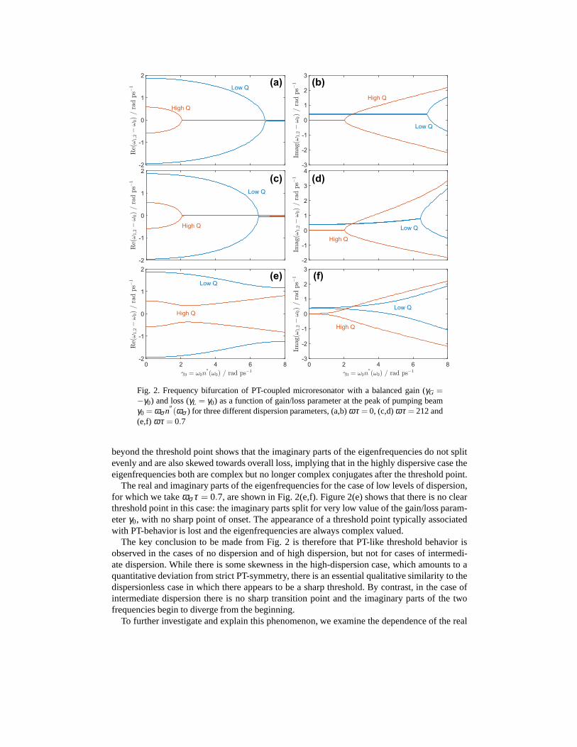
Fig. 2. Frequency bifurcation of PT-coupled microresonator with a balanced gain (γG =−γ0) and loss (γL = γ0) as a function of gain/loss parameter at the peak of pumping beamγ0 = ωσ n
′′(ωσ ) for three different dispersion parameters, (a,b)ωτ = 0, (c,d)ωτ = 212 and
(e,f) ωτ = 0.7
beyond the threshold point shows that the imaginary parts ofthe eigenfrequencies do not splitevenly and are also skewed towards overall loss, implying that in the highly dispersive case theeigenfrequencies both are complex but no longer complex conjugates after the threshold point.
The real and imaginary parts of the eigenfrequencies for thecase of low levels of dispersion,for which we takeωσ τ = 0.7, are shown in Fig. 2(e,f). Figure 2(e) shows that there is noclearthreshold point in this case: the imaginary parts split for very low value of the gain/loss param-eterγ0, with no sharp point of onset. The appearance of a threshold point typically associatedwith PT-behavior is lost and the eigenfrequencies are always complex valued.
The key conclusion to be made from Fig. 2 is therefore that PT-like threshold behavior isobserved in the cases of no dispersion and of high dispersion, but not for cases of intermedi-ate dispersion. While there is some skewness in the high-dispersion case, which amounts to aquantitative deviation from strict PT-symmetry, there is an essential qualitative similarity to thedispersionless case in which there appears to be a sharp threshold. By contrast, in the case ofintermediate dispersion there is no sharp transition pointand the imaginary parts of the twofrequencies begin to diverge from the beginning.
To further investigate and explain this phenomenon, we examine the dependence of the real
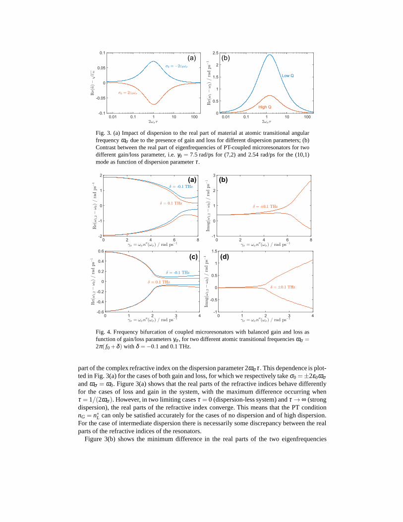
Fig. 3. (a) Impact of dispersion to the real part of material at atomic transitional angularfrequencyωσ due to the presence of gain and loss for different dispersionparameters; (b)Contrast between the real part of eigenfrequencies of PT-coupled microresonators for twodifferent gain/loss parameter, i.e.γ0 = 7.5 rad/ps for (7,2) and 2.54 rad/ps for the (10,1)mode as function of dispersion parameterτ.
Fig. 4. Frequency bifurcation of coupled microresonators with balanced gain and loss asfunction of gain/loss parametersγσ , for two different atomic transitional frequenciesωσ =2π( f0+δ ) with δ =−0.1 and 0.1 THz.
part of the complex refractive index on the dispersion parameter 2ωσ τ. This dependence is plot-ted in Fig. 3(a) for the cases of both gain and loss, for which we respectively takeσ0 =±2ε0ωσandωσ = ω0. Figure 3(a) shows that the real parts of the refractive indices behave differentlyfor the cases of loss and gain in the system, with the maximum difference occurring whenτ = 1/(2ωσ ). However, in two limiting casesτ = 0 (dispersion-less system) andτ → ∞ (strongdispersion), the real parts of the refractive index converge. This means that the PT conditionnG = n∗L can only be satisfied accurately for the cases of no dispersion and of high dispersion.For the case of intermediate dispersion there is necessarily some discrepancy between the realparts of the refractive indices of the resonators.
Figure 3(b) shows the minimum difference in the real parts ofthe two eigenfrequencies
for different dispersion levels and operated at a fixed valueof the gain/loss parameter, i.e. atγ0 = 7.5 rad/ps for the lowQ-factor and at 2.54 rad/ps for highQ-factor modes of operation.These values of the gain/loss parameter are chosen to lie above the expected threshold so thatqualitatively PT-like behavior would imply eigenfrequencies with a common real part. Figures3(a) and 3(b) confirm that the maximum difference between real parts of the two refractiveindices coincides with the maximum deviation from PT-like threshold behavior, where the dif-ference between real parts of the eigenfrequencies is greatest. This result further confirms thefact that realistic levels of dispersion preserve the essential features of PT behavior.
Having confirmed that realistic levels of dispersion preserve PT behavior, Figure 4 considersa practical scenario in which there is high dispersionωσ τ = 212 and a frequency mismatch be-tween the resonant frequency and the gain/loss atomic angular frequency. The material atomicfrequency is defined to beωσ = 2π( f0+δ ), whereδ is the mismatch parameter. The structureis operated with balanced gain and loss, i.e.γG = −γL and two values are assumed for the fre-quency mismatch, namelyδ = −0.1 and 0.1 THz. Figure 4(a,b) shows the results for the lowQ-factor mode (7,2) and Fig. 4(c,d) for the high-Q factor mode (10,1). In both cases there isno sharp threshold point for the real parts of eigenfrequencies and the imaginary parts beginto diverge at low gain/loss values. Neither are the imaginary parts symmetrically placed abouta branching value. This result confirms the fact that PT behavior is preserved only when theangular transitional frequency of the dispersive gain/loss profile is aligned with the resonantfrequency of the microresonators. If that is not the case, the frequency misalignment causes thecoupled system to continue to beat after a threshold region.
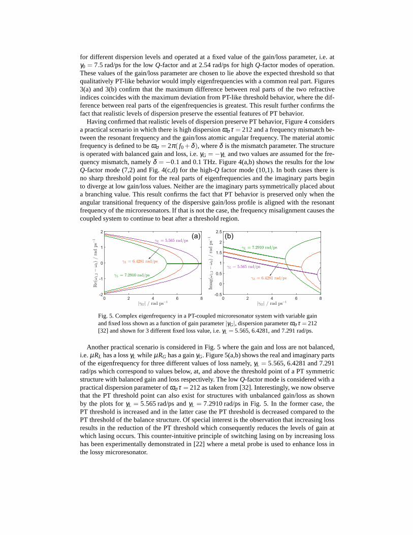
Fig. 5. Complex eigenfrequency in a PT-coupled microresonator system with variable gainand fixed loss shown as a function of gain parameter|γG|, dispersion parameterωσ τ = 212[32] and shown for 3 different fixed loss value, i.e.γL = 5.565, 6.4281, and 7.291 rad/ps.
Another practical scenario is considered in Fig. 5 where thegain and loss are not balanced,i.e.µRL has a lossγL while µRG has a gainγG. Figure 5(a,b) shows the real and imaginary partsof the eigenfrequency for three different values of loss namely, γL = 5.565, 6.4281 and 7.291rad/ps which correspond to values below, at, and above the threshold point of a PT symmetricstructure with balanced gain and loss respectively. The lowQ-factor mode is considered with apractical dispersion parameter ofωσ τ = 212 as taken from [32]. Interestingly, we now observethat the PT threshold point can also exist for structures with unbalanced gain/loss as shownby the plots forγL = 5.565 rad/ps andγL = 7.2910 rad/ps in Fig. 5. In the former case, thePT threshold is increased and in the latter case the PT threshold is decreased compared to thePT threshold of the balance structure. Of special interest is the observation that increasing lossresults in the reduction of the PT threshold which consequently reduces the levels of gain atwhich lasing occurs. This counter-intuitive principle of switching lasing on by increasing losshas been experimentally demonstrated in [22] where a metal probe is used to enhance loss inthe lossy microresonator.
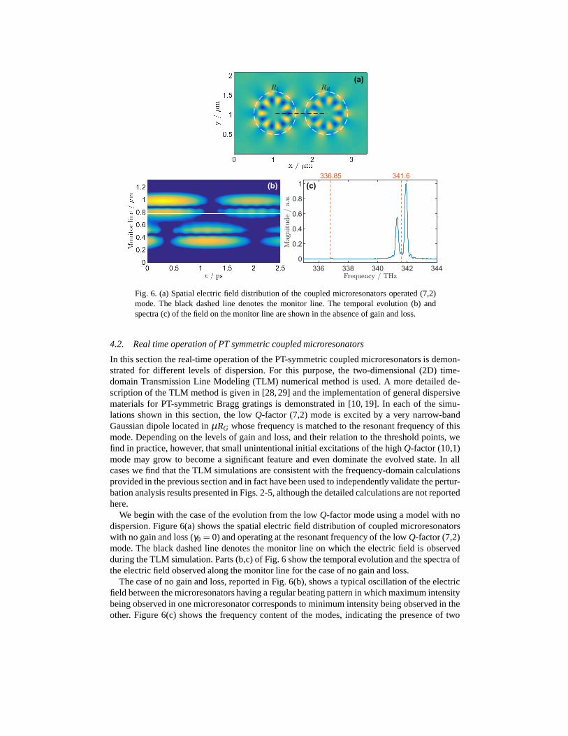
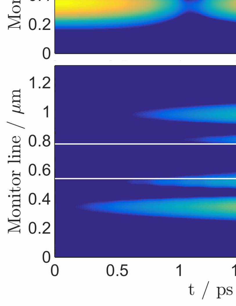
Fig. 6. (a) Spatial electric field distribution of the coupled microresonators operated (7,2)mode. The black dashed line denotes the monitor line. The temporal evolution (b) andspectra (c) of the field on the monitor line are shown in the absence of gain and loss.
4.2. Real time operation of PT symmetric coupled microresonators
In this section the real-time operation of the PT-symmetriccoupled microresonators is demon-strated for different levels of dispersion. For this purpose, the two-dimensional (2D) time-domain Transmission Line Modeling (TLM) numerical method is used. A more detailed de-scription of the TLM method is given in [28, 29] and the implementation of general dispersivematerials for PT-symmetric Bragg gratings is demonstratedin [10, 19]. In each of the simu-lations shown in this section, the lowQ-factor (7,2) mode is excited by a very narrow-bandGaussian dipole located inµRG whose frequency is matched to the resonant frequency of thismode. Depending on the levels of gain and loss, and their relation to the threshold points, wefind in practice, however, that small unintentional initialexcitations of the highQ-factor (10,1)mode may grow to become a significant feature and even dominate the evolved state. In allcases we find that the TLM simulations are consistent with thefrequency-domain calculationsprovided in the previous section and in fact have been used toindependently validate the pertur-bation analysis results presented in Figs. 2-5, although the detailed calculations are not reportedhere.
We begin with the case of the evolution from the lowQ-factor mode using a model with nodispersion. Figure 6(a) shows the spatial electric field distribution of coupled microresonatorswith no gain and loss (γ0 = 0) and operating at the resonant frequency of the lowQ-factor (7,2)mode. The black dashed line denotes the monitor line on whichthe electric field is observedduring the TLM simulation. Parts (b,c) of Fig. 6 show the temporal evolution and the spectra ofthe electric field observed along the monitor line for the case of no gain and loss.
The case of no gain and loss, reported in Fig. 6(b), shows a typical oscillation of the electricfield between the microresonators having a regular beating pattern in which maximum intensitybeing observed in one microresonator corresponds to minimum intensity being observed in theother. Figure 6(c) shows the frequency content of the modes,indicating the presence of two
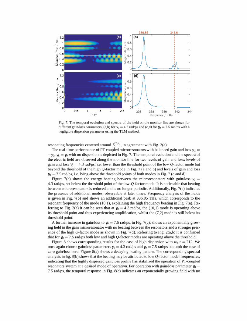
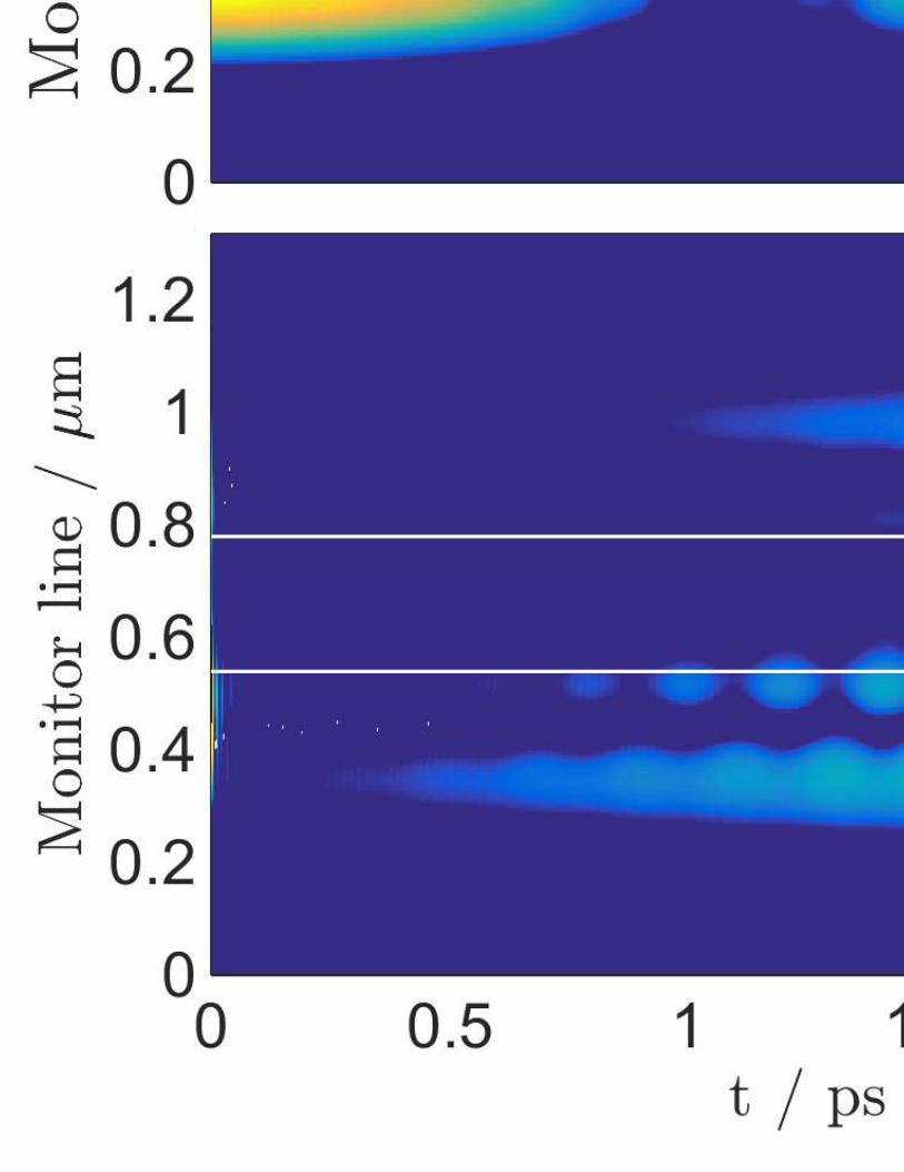
Fig. 7. The temporal evolution and spectra of the field on the monitor line are shown fordifferent gain/loss parameters, (a,b) forγ0 = 4.3 rad/ps and (c,d) forγ0 = 7.5 rad/ps with anegligible dispersion parameter using the TLM method.
resonating frequencies centered aroundf (7,2)0 , in agreement with Fig. 2(a).The real-time performance of PT-coupled microresonators with balanced gain and lossγG =
−γ0, γL = γ0 with no dispersion is depicted in Fig. 7. The temporal evolution and the spectra ofthe electric field are observed along the monitor line for twolevels of gain and loss: levels ofgain and lossγ0 = 4.3 rad/ps, i.e. lower than the threshold point of the lowQ-factor mode butbeyond the threshold of the high Q-factor mode in Fig. 7 (a andb) and levels of gain and lossγ0 = 7.5 rad/ps, i.e. lying above the threshold points of both modesin Fig. 7 (c and d).
Figure 7(a) shows the energy beating between the microresonators with gain/lossγ0 =4.3 rad/ps, set below the threshold point of the low-Q-factor mode. It is noticeable that beatingbetween microresonators is reduced and is no longer periodic. Additionally, Fig. 7(a) indicatesthe presence of additional modes, observable at later times. Frequency analysis of the fieldsis given in Fig. 7(b) and shows an additional peak at 336.85 THz, which corresponds to theresonant frequency of the mode (10,1), explaining the high frequency beating in Fig. 7(a). Re-ferring to Fig. 2(a) it can be seen that atγ0 = 4.3 rad/ps, the (10,1) mode is operating aboveits threshold point and thus experiencing amplification, whilst the (7,2) mode is still below itsthreshold point.
A further increase in gain/loss toγ0 = 7.5 rad/ps, in Fig. 7(c), shows an exponentially grow-ing field in the gain microresonator with no beating between the resonators and a stronger pres-ence of the highQ-factor mode as shown in Fig. 7(d). Referring to Fig. 2(a,b) it is confirmedthat forγ0 = 7.5 rad/ps both low and highQ-factor modes are operating above the threshold.
Figure 8 shows corresponding results for the case of high dispersion withωσ τ = 212. Weonce again choose gain/loss parametersγ0 = 4.3 rad/ps andγ0 = 7.5 rad/ps but omit the case ofzero gain/loss here. Figure 8(a) shows a decaying beating pattern. The corresponding spectralanalysis in fig. 8(b) shows that the beating may be attributedto low Q-factor modal frequencies,indicating that the highly dispersed gain/loss profile has stabilized the operation of PT-coupledresonators system at a desired mode of operation. For operation with gain/loss parameterγ0 =7.5 rad/ps, the temporal response in Fig. 8(c) indicates an exponentially growing field with no
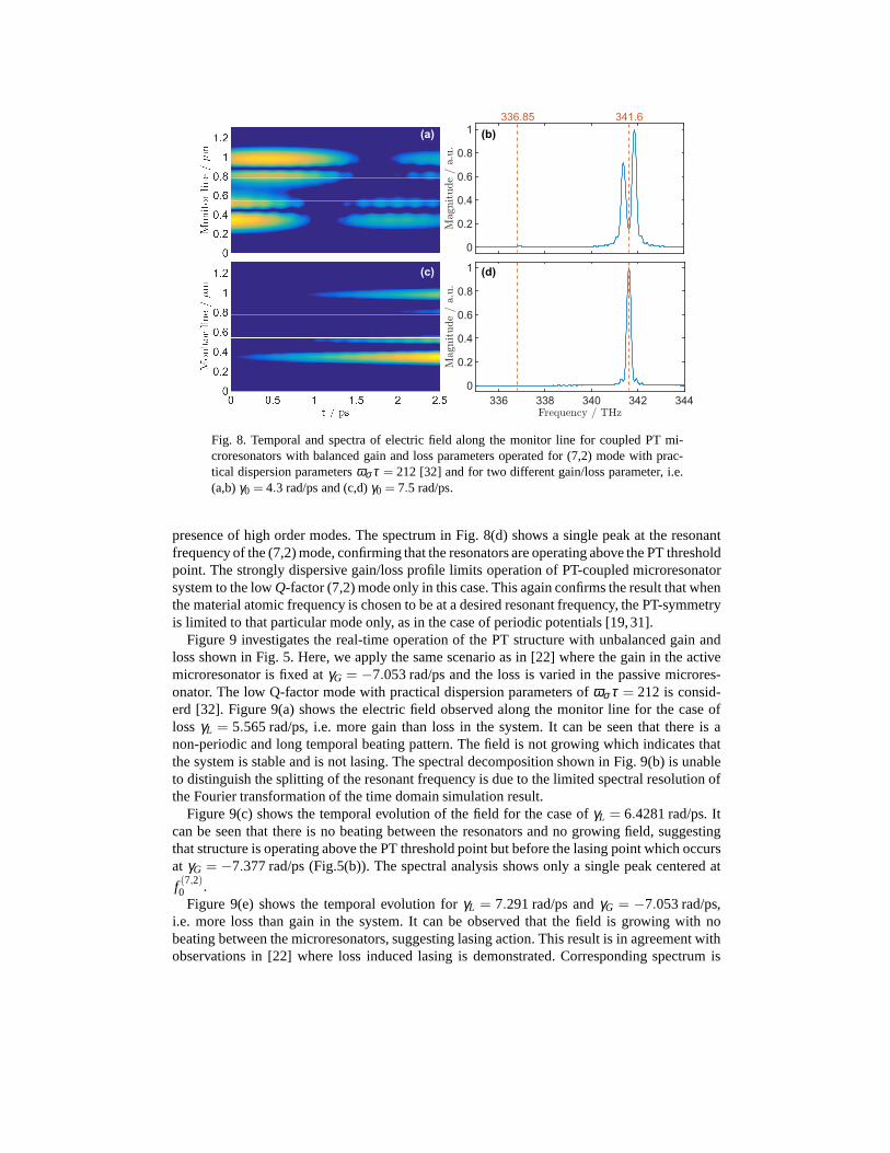
Fig. 8. Temporal and spectra of electric field along the monitor line for coupled PT mi-croresonators with balanced gain and loss parameters operated for (7,2) mode with prac-tical dispersion parametersωσ τ = 212 [32] and for two different gain/loss parameter, i.e.(a,b)γ0 = 4.3 rad/ps and (c,d)γ0 = 7.5 rad/ps.
presence of high order modes. The spectrum in Fig. 8(d) showsa single peak at the resonantfrequency of the (7,2) mode, confirming that the resonators are operating above the PT thresholdpoint. The strongly dispersive gain/loss profile limits operation of PT-coupled microresonatorsystem to the lowQ-factor (7,2) mode only in this case. This again confirms the result that whenthe material atomic frequency is chosen to be at a desired resonant frequency, the PT-symmetryis limited to that particular mode only, as in the case of periodic potentials [19,31].
Figure 9 investigates the real-time operation of the PT structure with unbalanced gain andloss shown in Fig. 5. Here, we apply the same scenario as in [22] where the gain in the activemicroresonator is fixed atγG = −7.053 rad/ps and the loss is varied in the passive microres-onator. The low Q-factor mode with practical dispersion parameters ofωσ τ = 212 is consid-erd [32]. Figure 9(a) shows the electric field observed alongthe monitor line for the case ofloss γL = 5.565 rad/ps, i.e. more gain than loss in the system. It can be seen that there is anon-periodic and long temporal beating pattern. The field isnot growing which indicates thatthe system is stable and is not lasing. The spectral decomposition shown in Fig. 9(b) is unableto distinguish the splitting of the resonant frequency is due to the limited spectral resolution ofthe Fourier transformation of the time domain simulation result.
Figure 9(c) shows the temporal evolution of the field for the case ofγL = 6.4281 rad/ps. Itcan be seen that there is no beating between the resonators and no growing field, suggestingthat structure is operating above the PT threshold point butbefore the lasing point which occursat γG = −7.377 rad/ps (Fig.5(b)). The spectral analysis shows only a single peak centered at
f (7,2)0 .Figure 9(e) shows the temporal evolution forγL = 7.291 rad/ps andγG = −7.053 rad/ps,
i.e. more loss than gain in the system. It can be observed thatthe field is growing with nobeating between the microresonators, suggesting lasing action. This result is in agreement withobservations in [22] where loss induced lasing is demonstrated. Corresponding spectrum is
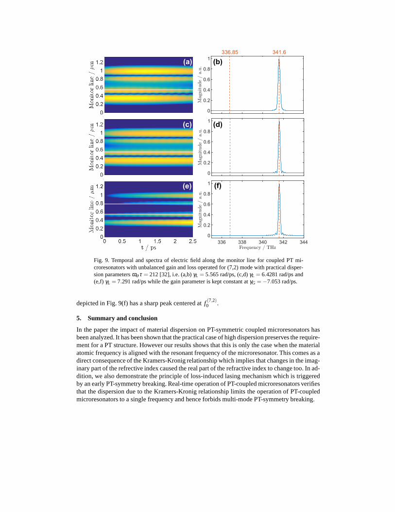
Fig. 9. Temporal and spectra of electric field along the monitor line for coupled PT mi-croresonators with unbalanced gain and loss operated for (7,2) mode with practical disper-sion parametersωσ τ = 212 [32], i.e. (a,b)γL = 5.565 rad/ps, (c,d)γL = 6.4281 rad/ps and(e,f) γL = 7.291 rad/ps while the gain parameter is kept constant atγG =−7.053 rad/ps.
depicted in Fig. 9(f) has a sharp peak centered atf (7,2)0 .
5. Summary and conclusion
In the paper the impact of material dispersion on PT-symmetric coupled microresonators hasbeen analyzed. It has been shown that the practical case of high dispersion preserves the require-ment for a PT structure. However our results shows that this is only the case when the materialatomic frequency is aligned with the resonant frequency of the microresonator. This comes as adirect consequence of the Kramers-Kronig relationship which implies that changes in the imag-inary part of the refrective index caused the real part of therefractive index to change too. In ad-dition, we also demonstrate the principle of loss-induced lasing mechanism which is triggeredby an early PT-symmetry breaking. Real-time operation of PT-coupled microresonators verifiesthat the dispersion due to the Kramers-Kronig relationshiplimits the operation of PT-coupledmicroresonators to a single frequency and hence forbids multi-mode PT-symmetry breaking.