Parametric Study on Offshore Jacket Launching
21
Ocean Engineering 29 (2002) 1959–1979 Technical Note Parametric study on offshore jacket launching C.H. Jo * , K.S. Kim, S.H. Lee Department of Naval Architecture and Ocean Engineering, Inha University, Inchon 40-751, South Korea Received 22 February 2001; received in revised form 12 June 2001; accepted 25 October 2001 Abstract Platform structures are commonly utilized for various purposes including offshore drilling, processing and support of offshore operations. Jacket type structures are attractive in relatively shallow water regions. A jacket is a supporting structure for deck facilities stabilized by leg piles through the seabed. The size of a jacket is dependent on deck size, pile dimensions and environmental loads. In a jacket design, operational and environmental loads are very important and must be investigated intensively to secure the stability of structures during their operation life, and installation phase as well. To confirm the stability, several analyses includ- ing in-place, fatigue, dynamic, load-out, transportation, lifting, and launching are performed. As the jacket weight and dimensions become large, a launching technique is applied to install the jacket. The launching analysis needs to consider quite a number of parameters including environmental conditions, launch barge specification, ballast, trim angle, local member integ- rity, etc. Due to the complexity of the operation, there is not a straightforward guideline or procedure for analysis. In this paper, a general procedure for analysis with various conditions and launching criteria are discussed and investigated. The effects of parameters are closely examined by numerical modeling. 2002 Elsevier Science Ltd. All rights reserved. Keywords: Launching; Parametric study; Tilting beam; Jacket 1. Introduction One of the important factors in offshore jacket design is to determine an instal- lation method. Depending on the installation method the stresses to members during * Corresponding author. Tel.: +82-32-860-7342; fax: +82-32-864-5850. E-mail address: [email protected] (C.H. Jo). 0029-8018/02/$ - see front matter 2002 Elsevier Science Ltd. All rights reserved. PII:S0029-8018(01)00108-1
-
Upload
chacky-kong -
Category
Documents
-
view
59 -
download
5
Transcript of Parametric Study on Offshore Jacket Launching
Ocean Engineering 29 (2002) 1959–1979
Technical Note
Parametric study on offshore jacket launching
C.H. Jo*, K.S. Kim, S.H. LeeDepartment of Naval Architecture and Ocean Engineering, Inha University, Inchon 40-751,
South Korea
Received 22 February 2001; received in revised form 12 June 2001; accepted 25 October 2001
Abstract
Platform structures are commonly utilized for various purposes including offshore drilling,processing and support of offshore operations. Jacket type structures are attractive in relativelyshallow water regions. A jacket is a supporting structure for deck facilities stabilized by legpiles through the seabed. The size of a jacket is dependent on deck size, pile dimensions andenvironmental loads. In a jacket design, operational and environmental loads are veryimportant and must be investigated intensively to secure the stability of structures during theiroperation life, and installation phase as well. To confirm the stability, several analyses includ-ing in-place, fatigue, dynamic, load-out, transportation, lifting, and launching are performed.As the jacket weight and dimensions become large, a launching technique is applied to installthe jacket. The launching analysis needs to consider quite a number of parameters includingenvironmental conditions, launch barge specification, ballast, trim angle, local member integ-rity, etc. Due to the complexity of the operation, there is not a straightforward guideline orprocedure for analysis. In this paper, a general procedure for analysis with various conditionsand launching criteria are discussed and investigated. The effects of parameters are closelyexamined by numerical modeling. 2002 Elsevier Science Ltd. All rights reserved.
Keywords: Launching; Parametric study; Tilting beam; Jacket
1. Introduction
One of the important factors in offshore jacket design is to determine an instal-lation method. Depending on the installation method the stresses to members during
* Corresponding author. Tel.:+82-32-860-7342; fax:+82-32-864-5850.E-mail address: [email protected] (C.H. Jo).
0029-8018/02/$ - see front matter 2002 Elsevier Science Ltd. All rights reserved.PII: S0029 -8018(01 )00108-1
1960 C.H. Jo et al. / Ocean Engineering 29 (2002) 1959–1979
installation become significant, and should be applied to the structural arrangement,selection of member dimensions and specifications. For large jacket installations, alaunching method is often applied. Even when the launching process occurs in arelatively short time, the operation decides the success or failure of the installation(Noble, Denton and Associates, 1984). This operation is the most critical in the entireinstallation procedure. The failure could result in damage to local members, defectsto the transportation barge, overturning of the unit (jacket and barge together), andeven total loss of the structure (Gerwick, 1986).
Whatever the cause, the failure of the launching implicates a delay of the construc-tion period and an economic loss. The launching analysis needs to consider a numberof parameters, including the environment, jacket, launch barge and launch conditions.The analysis can be executed by separating the launch phases. The purpose of launch-ing is to separate the structure from its barge safely and economically. The optimiz-ation of launching design is necessary to minimize the stress to jacket and barge(API, 1993).
During the initiation stage, a barge is trimmed by ballasting compartments. Inaddition, supplementary equipment like hydraulic jacks and winches are equippedto assist in sliding the jacket. On the deck of the barge, a heavy runner beam orskid rail is placed longitudinally to transfer the jacket weight and to slide the structureduring launching. In the stern, a rocker arm and a tilting beam that can support theentire load for a short period are attached. During the launching operation, since thereaction force is transferred to jacket, the length of the tilting beam is designed tobe long enough to distribute the load (Chakrabarti, 1995).
The launching operation takes place in calm water. After most of the sea-fasteningcomponents are removed, ballasting starts to maintain a range of about 2 to 4 degreesin which the structure does not slide with its own weight. However, an excessivetilting angle can cause jacket stalling that can endanger the launching operation withpotential hazards to the structure and the barge (Lee, 2000).
As the center of weight moves to the rocker arm pin, the rocker arm rotates upto the maximum allowable angle and the jacket slides and launches into the sea.After the launch, due to buoyancy, it emerges on the surface after a certain time.This stage takes around 60 seconds for a medium sized jacket in 120 to 150 meterswater depths.
The most important and critical stage in the launching process is when it is beingseparated from the barge. The analysis should be focused on this stage to check thepossible structural failure or overturning of the barge (KAIST-a, 1985; KAIST-b,1985). It is very important to investigate and optimize the pre-launching conditionsprior to separation. The launch trajectory that minimizes the reaction force to thejacket must be studied. The factors that influence launching vary with barge con-ditions and structure specifications. The details of the influence factors for barge andjacket are described below:
1.1. Barge
The influence factors change according to the launching conditions even whenusing the same barge. The pre-launch condition is dependent on draft, trim and tiltingbeam length that contribute based on the following parameters:
1961C.H. Jo et al. / Ocean Engineering 29 (2002) 1959–1979
— rocker tipping load— length of launch leg remaining on rockers— barge submerging depth— jacket dive depth— slide velocity of horizontal braces— stability of barge during launch— longitudinal strength of barge
In this paper the optimization for the three pre-launching conditions, consideringthe above seven parameters, is conducted.
1.2. Jacket
The jacket type and dimensions are not uniform but differ for each case. However,the influence parameters for thejacket during launching are decided as:
— center of gravity— center of buoyancy— reserved buoyancy quantity— jacket length/tilting beam length ratio
By changing the above parameters and considering the pre-launch conditions, theeffects of these parameters are investigated. Since the jacket should float after launch-ing, it has reserved buoyancy to satisfy the stable condition. During launching, thecenters of weight and buoyancy of the jacket change continuously. In the course ofthe process, the structure should have sufficient strength and stability. In general,the reserved buoyancy is required in the range from 10 to 20% of the jacket weight.To perform a stable upending operation, more than 10 meters of GM is to be main-tained for medium jackets of 50 to 150 meters long during the initial floating stage.Therefore, in the analysis the guidelines below are implicated:
— reserved buoyancy: 10 to 20% of the jacket weight— GM�10 m for floating.
2. Load estimation
2.1. Equation of motion
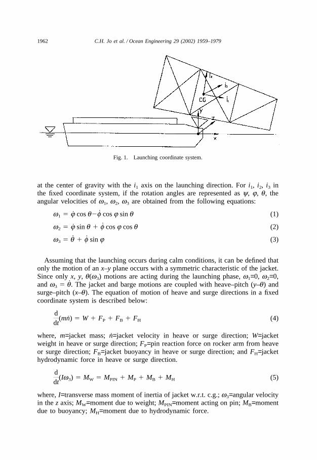
The loads to the jacket during launching are self-weight, inertia force due to jacketmotion, buoyancy, hydrodynamic drag and inertia forces, and the constraint forcefrom the barge and jacket interface. As illustrated in Fig. 1 in the space fixed coordi-nate system, the origin of the coordinates lies at the free surface; the x-axis on thelaunching direction and the y-axis on the vertical direction toward the tilting beampin (Ultramarine Inc., 1999). In the structure fixed coordinate system, the origin stays
1962 C.H. Jo et al. / Ocean Engineering 29 (2002) 1959–1979
Fig. 1. Launching coordinate system.
at the center of gravity with the i1 axis on the launching direction. For i1, i2, i3 inthe fixed coordinate system, if the rotation angles are represented as y, j, q, theangular velocities of w1, w2, w3 are obtained from the following equations:
w1 � j cos q�f cos j sin q (1)
w2 � j sin q � f cos j cos q (2)
w3 � q � f sin j (3)
Assuming that the launching occurs during calm conditions, it can be defined thatonly the motion of an x–y plane occurs with a symmetric characteristic of the jacket.Since only x, y, q(w3) motions are acting during the launching phase, w1=0, w2=0,and w3 � q. The jacket and barge motions are coupled with heave–pitch (y–q) andsurge–pitch (x–q). The equation of motion of heave and surge directions in a fixedcoordinate system is described below:
ddt
(mn) � W � FP � FB � FH (4)
where, m=jacket mass; n=jacket velocity in heave or surge direction; W=jacketweight in heave or surge direction; FP=pin reaction force on rocker arm from heaveor surge direction; FB=jacket buoyancy in heave or surge direction; and FH=jackethydrodynamic force in heave or surge direction.
ddt
(Iw3) � MW � MPIN � MP � MB � MH (5)
where, I=transverse mass moment of inertia of jacket w.r.t. c.g.; w3=angular velocityin the z axis; MW=moment due to weight; MPIN=moment acting on pin; MB=momentdue to buoyancy; MH=moment due to hydrodynamic force.

1963C.H. Jo et al. / Ocean Engineering 29 (2002) 1959–1979
2.2. Applied loads
From a launch trajectory study, the applied loads on the structure can be obtainedand employed in the structural analysis. When the maximum moment occurs, thejacket is supported only by the rocker arm. And right after the tilting beam is tilted,the jacket inertia force increases as its dynamic motion increases. Also most of thejacket weight except a small portion of buoyancy in the upper part acts on the rockerarm. The reaction force from the pin acts as a constraint force due to the barge andjacket interface. The constraint force will act on the jacket as a distributing load onthe launch leg along the tilting beam. As the distribution loads are applied to thetilting beam, the constraint force acts on the launch leg. The reaction force of thepin is composed of normal and tangential components. And the reaction force to thetangential direction is described as:
FTP � FdFNP (6)
where, Fd=friction coefficient between launch runner and tilting beam; FNP=normalreaction force.
The constraint force can be decided from the equilibrium condition between thereaction force obtained from the tilting beam and the entire weight of the structure.The hydrodynamic force consists of drag, added mass and hydro-damping forces.Even the hydro-damping force is present in a fluid field having free surface, but thisforce is neglected in launching analysis. In this case, the launching velocity becomesa little bit higher than in actual operation, and consequently it reduces the appliedload on the tilting beam by shortening the remaining period the jacket spends onthe tilting beam. However, from the results of this study, assuming that it is themotion with frequency, it is found that the quantity of reduced force doesn’ t affectthe analysis significantly. Therefore, only drag and inertia forces, neglecting thedamping force, are implicated in the analysis. The drag force, FD, and the inertiaforce, FI, are represented in eqns (7) and (8), respectively:
FD � �12
CDrAWUn|Un| (7)
where, CD=drag coefficient; r=fluid density; AW=submerged area; Un=vertical velo-city.
FI � CMrVUn (8)
where, CM=inertia coefficient; V=submerged volumn; Un=vertical acceleration.The velocity at an arbitrary point, P, of the structure is
UP � UCG � w × g (9)
where, UP=structure velocity at P; UCG=sliding velocity; w=angular velocity at CG;g=position vector from CG to P.
By differentiating eqn. (9) w.r.t. time, t, the acceleration at point P can bederived as:
1964 C.H. Jo et al. / Ocean Engineering 29 (2002) 1959–1979
UP � UCG � (w × g) � (w2 × g) (10)
where, UP=structure acceleration at P; UCG=sliding acceleration; w=angular acceler-ation of CG.
3. Launch analysis
The launching analysis was conducted with a FEM module named SACS(Ultramarine Inc., 1999) that can simulate the motion of a structure being launched.The analysis includes a time history description of the jacket and barge motionscontaining displacement, velocity and acceleration. Although the launch motion isconstrained to the vertical plane, hydrodynamic forces are considered in three dimen-sions with the hydrodynamic characteristics of the barge. The forces on the jacketbeing encountered during launching can be generated in the study.
The motions of jacket and barge can be classified into five launch phases:
(a) Phase 1 motion occurs when the structure is sliding on the barge due to thewinch with no tipping of the rocker arm.(b) Phase 2 motion is defined when the structure is sliding on the barge due togravity or self-weight with no tipping of the rocker arm.(c) Phase 3 motion occurs when the structure is sliding due to the winch with atipping of the rocker arm.(d) Phase 4 motion results from the structure sliding due to self-weight (gravity)with a tipping on the rocker arm.(e) Phase 5 is the motion that occurs after the structure and the barge are separated.
The launch analyses are executed in one of three modes as detailed below:
(a) time history analysis including the behavior of jacket on the barge at spe-cific stages;(b) an analysis for change of structure position from the final time step of theprevious mode;(c) a post launch analysis consisting of launch loads for a particular time step.
The input data can be divided into five categories; barge1, barge2, barge anchor,tug boat and launch runner. The barge dimensions including its height, draft, aftextension, width and forward extension are required to estimate the weight and buoy-ancy of the barge. The skid and rocker arm with skid height, rocker arm pin locationand rocker arm depth are required as well. The barge anchor, if applied, is alsonecessary containing anchor line length, holding power and friction coefficient.
4. Modeling
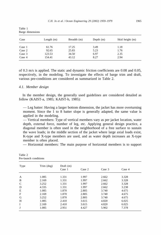
To conduct a parametric study, four barges and four jackets are modeled. Theprime dimensions of barges are as shown in Table 1. In the analysis, the winch speed
1965C.H. Jo et al. / Ocean Engineering 29 (2002) 1959–1979
Table 1Barge dimensions
Case Length (m) Breadth (m) Depth (m) Skid height (m)
Case 1 61.76 17.25 3.49 1.18Case 2 92.65 25.83 5.23 1.76Case 3 123.53 34.50 6.97 2.35Case 4 154.41 43.12 8.27 2.94
of 0.3 m/s is applied. The static and dynamic friction coefficients are 0.08 and 0.05,respectively, in the modeling. To investigate the effects of barge trim and draft,various pre-conditions are considered as summarized in Table 2.
4.1. Member design
In the member design, the generally used guidelines are considered detailed asfollow (KAIST-a, 1985; KAIST-b, 1985):
— Leg batter: Having a larger bottom dimension, the jacket has more overturningmoment. Since the 1 to 8 batter slope is generally adapted, the same value isapplied in the modeling.— Vertical members: Type of vertical members vary as per jacket location, waterdepth, external force, number of leg, etc. Applying general design practice, adiagonal member is often used in the neighborhood of a free surface to sustainthe wave loads; in the middle section of the jacket where large axial loads exist,K-type and X-type members are used, and as water depth increases an X-typemember is often placed.— Horizontal members: The main purpose of horizontal members is to support
Table 2Pre-launch conditions
Type Trim (deg) Draft (m)Case 1 Case 2 Case 3 Case 4
A 1.085 1.331 1.997 2.662 3.328B 2.169 1.331 1.997 2.662 3.328C 3.252 1.331 1.997 2.662 3.328D 4.335 1.331 1.997 2.662 3.238E 1.085 1.870 2.805 3.740 4.675F 2.169 1.870 2.805 3.740 4.675G 3.252 1.870 2.805 3.740 4.675H 1.085 2.410 3.615 4.820 6.025I 2.169 2.410 3.615 4.820 6.025J 1.085 2.951 4.427 5.902 7.378
1966 C.H. Jo et al. / Ocean Engineering 29 (2002) 1959–1979
the jacket structures such as walking pass, anode, conductor, riser, etc., and alsoto prevent torsion of the jacket–pile system. Members in the upper area aredesigned to locate 1 meter above the splash zone to avoid wave loads.— Launch truss: In a launching process, the critical moment occurs when thejacket rotates at the rocker arm. At this stage, since the jacket weight is transferredto the rocker arm, the jacket is enforced to absorb the excessive loads when itpasses over the rocker arm. The enforced member is often called the launch trussand its weight occupies about 7% of jacket weight.
4.2. Member size and jacket type determination
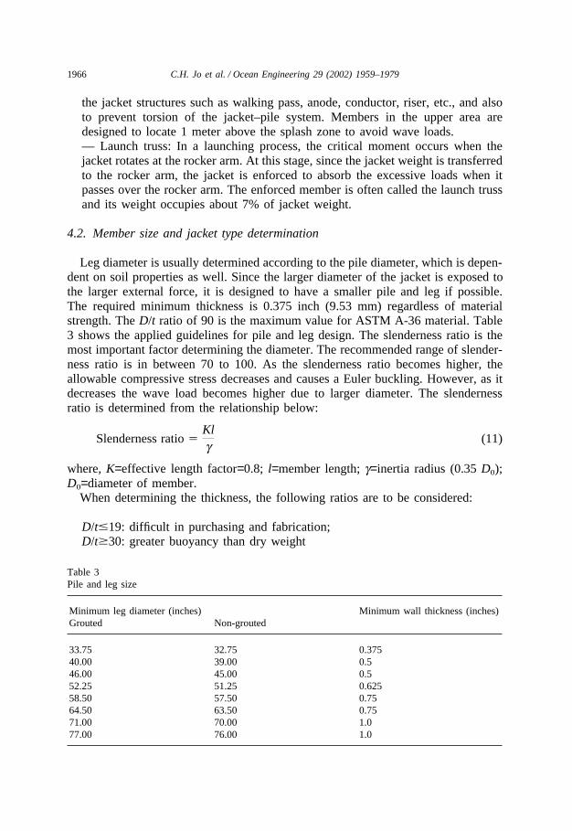
Leg diameter is usually determined according to the pile diameter, which is depen-dent on soil properties as well. Since the larger diameter of the jacket is exposed tothe larger external force, it is designed to have a smaller pile and leg if possible.The required minimum thickness is 0.375 inch (9.53 mm) regardless of materialstrength. The D/t ratio of 90 is the maximum value for ASTM A-36 material. Table3 shows the applied guidelines for pile and leg design. The slenderness ratio is themost important factor determining the diameter. The recommended range of slender-ness ratio is in between 70 to 100. As the slenderness ratio becomes higher, theallowable compressive stress decreases and causes a Euler buckling. However, as itdecreases the wave load becomes higher due to larger diameter. The slendernessratio is determined from the relationship below:
Slenderness ratio �Klg
(11)
where, K=effective length factor=0.8; l=member length; g=inertia radius (0.35 D0);D0=diameter of member.
When determining the thickness, the following ratios are to be considered:
D/t�19: difficult in purchasing and fabrication;D/t�30: greater buoyancy than dry weight
Table 3Pile and leg size
Minimum leg diameter (inches) Minimum wall thickness (inches)Grouted Non-grouted
33.75 32.75 0.37540.00 39.00 0.546.00 45.00 0.552.25 51.25 0.62558.50 57.50 0.7564.50 63.50 0.7571.00 70.00 1.077.00 76.00 1.0
1967C.H. Jo et al. / Ocean Engineering 29 (2002) 1959–1979
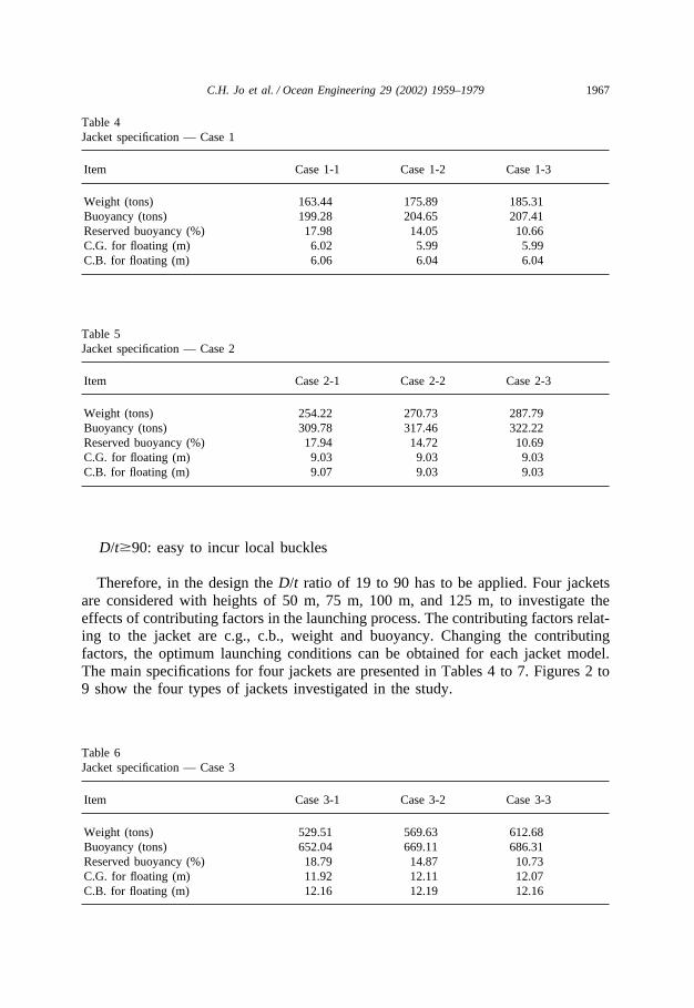
Table 4Jacket specification — Case 1
Item Case 1-1 Case 1-2 Case 1-3
Weight (tons) 163.44 175.89 185.31Buoyancy (tons) 199.28 204.65 207.41Reserved buoyancy (%) 17.98 14.05 10.66C.G. for floating (m) 6.02 5.99 5.99C.B. for floating (m) 6.06 6.04 6.04
Table 5Jacket specification — Case 2
Item Case 2-1 Case 2-2 Case 2-3
Weight (tons) 254.22 270.73 287.79Buoyancy (tons) 309.78 317.46 322.22Reserved buoyancy (%) 17.94 14.72 10.69C.G. for floating (m) 9.03 9.03 9.03C.B. for floating (m) 9.07 9.03 9.03
D/t�90: easy to incur local buckles
Therefore, in the design the D/t ratio of 19 to 90 has to be applied. Four jacketsare considered with heights of 50 m, 75 m, 100 m, and 125 m, to investigate theeffects of contributing factors in the launching process. The contributing factors relat-ing to the jacket are c.g., c.b., weight and buoyancy. Changing the contributingfactors, the optimum launching conditions can be obtained for each jacket model.The main specifications for four jackets are presented in Tables 4 to 7. Figures 2 to9 show the four types of jackets investigated in the study.
Table 6Jacket specification — Case 3
Item Case 3-1 Case 3-2 Case 3-3
Weight (tons) 529.51 569.63 612.68Buoyancy (tons) 652.04 669.11 686.31Reserved buoyancy (%) 18.79 14.87 10.73C.G. for floating (m) 11.92 12.11 12.07C.B. for floating (m) 12.16 12.19 12.16
1968 C.H. Jo et al. / Ocean Engineering 29 (2002) 1959–1979
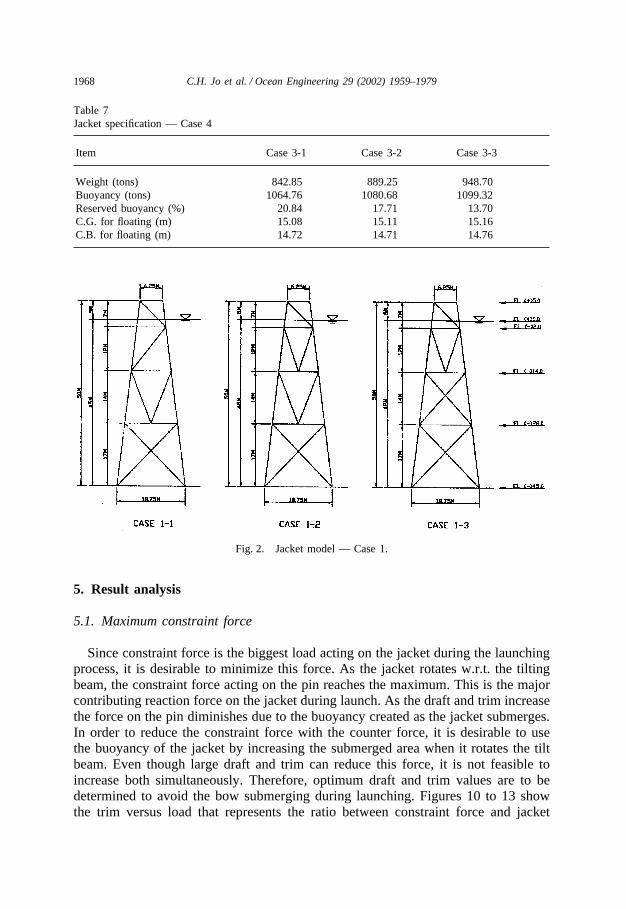
Table 7Jacket specification — Case 4
Item Case 3-1 Case 3-2 Case 3-3
Weight (tons) 842.85 889.25 948.70Buoyancy (tons) 1064.76 1080.68 1099.32Reserved buoyancy (%) 20.84 17.71 13.70C.G. for floating (m) 15.08 15.11 15.16C.B. for floating (m) 14.72 14.71 14.76
Fig. 2. Jacket model — Case 1.
5. Result analysis
5.1. Maximum constraint force
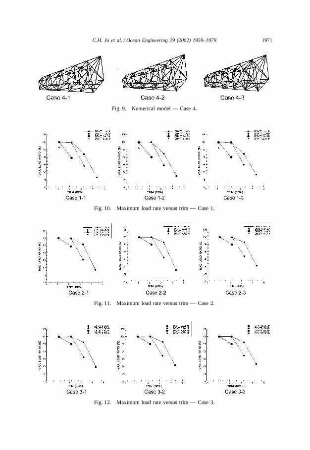
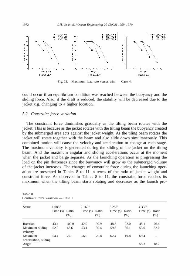
Since constraint force is the biggest load acting on the jacket during the launchingprocess, it is desirable to minimize this force. As the jacket rotates w.r.t. the tiltingbeam, the constraint force acting on the pin reaches the maximum. This is the majorcontributing reaction force on the jacket during launch. As the draft and trim increasethe force on the pin diminishes due to the buoyancy created as the jacket submerges.In order to reduce the constraint force with the counter force, it is desirable to usethe buoyancy of the jacket by increasing the submerged area when it rotates the tiltbeam. Even though large draft and trim can reduce this force, it is not feasible toincrease both simultaneously. Therefore, optimum draft and trim values are to bedetermined to avoid the bow submerging during launching. Figures 10 to 13 showthe trim versus load that represents the ratio between constraint force and jacket
1969C.H. Jo et al. / Ocean Engineering 29 (2002) 1959–1979
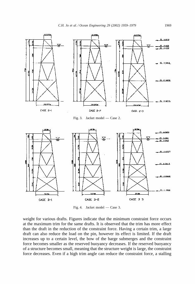
Fig. 3. Jacket model — Case 2.
Fig. 4. Jacket model — Case 3.
weight for various drafts. Figures indicate that the minimum constraint force occursat the maximum trim for the same drafts. It is observed that the trim has more effectthan the draft in the reduction of the constraint force. Having a certain trim, a largedraft can also reduce the load on the pin, however its effect is limited. If the draftincreases up to a certain level, the bow of the barge submerges and the constraintforce becomes smaller as the reserved buoyancy decreases. If the reserved buoyancyof a structure becomes small, meaning that the structure weight is large, the constraintforce decreases. Even if a high trim angle can reduce the constraint force, a stalling
1970 C.H. Jo et al. / Ocean Engineering 29 (2002) 1959–1979
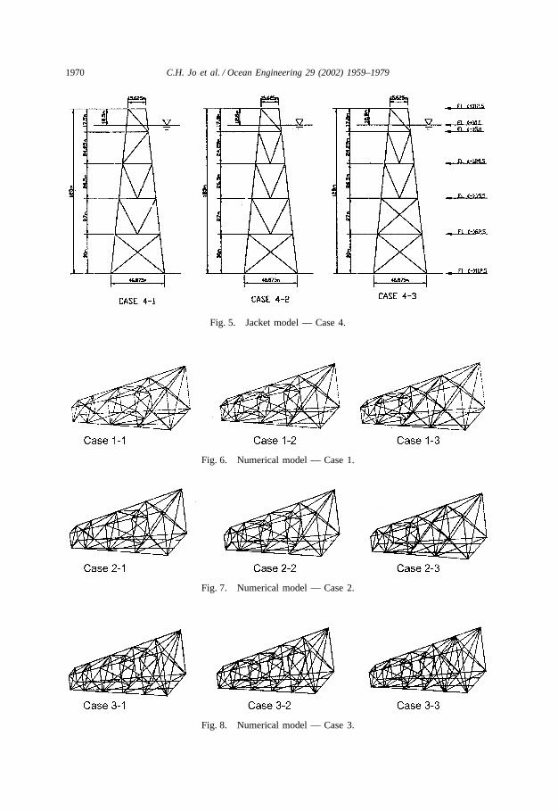
Fig. 5. Jacket model — Case 4.
Fig. 6. Numerical model — Case 1.
Fig. 7. Numerical model — Case 2.
Fig. 8. Numerical model — Case 3.
1971C.H. Jo et al. / Ocean Engineering 29 (2002) 1959–1979
Fig. 9. Numerical model — Case 4.
Fig. 10. Maximum load rate versus trim — Case 1.
Fig. 11. Maximum load rate versus trim — Case 2.
Fig. 12. Maximum load rate versus trim — Case 3.
1972 C.H. Jo et al. / Ocean Engineering 29 (2002) 1959–1979
Fig. 13. Maximum load rate versus trim — Case 4.
could occur if an equilibrium condition was reached between the buoyancy and thesliding force. Also, if the draft is reduced, the stability will be decreased due to thejacket c.g. changing to a higher location.
5.2. Constraint force variation
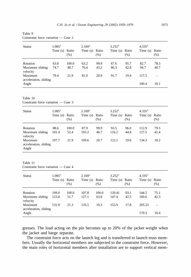
The constraint force diminishes gradually as the tilting beam rotates with thejacket. This is because as the jacket rotates with the tilting beam the buoyancy createdby the submerged area acts against the jacket weight. As the tiling beam rotates thejacket will rotate together with the beam and also slide down simultaneously. Thiscombined motion will cause the velocity and acceleration to change at each stage.The maximum velocity is generated during the sliding of the jacket on the tiltingbeam. And the maximum angular and sliding accelerations occur at the momentwhen the jacket and barge separate. As the launching operation is progressing theload on the pin decreases since the buoyancy will grow as the submerged volumeof the jacket increases. The changes of constraint force during the launching oper-ation are presented in Tables 8 to 11 in terms of the ratio of jacket weight andconstraint force. As observed in Tables 8 to 11, the constraint force reaches itsmaximum when the tilting beam starts rotating and decreases as the launch pro-
Table 8Constraint force variation — Case 1
Status 1.085° 2.169° 3.252° 4.335°Time (s) Ratio Time (s) Ratio Time (s) Ratio Time (s) Ratio
(%) (%) (%) (%)
Rotation 43.4 100.0 42.9 99.9 48.8 92.0 45.1 76.4Maximum sliding 52.0 43.6 53.4 39.4 59.8 36.1 53.0 32.0velocityMaximum 54.4 22.1 56.0 20.8 62.4 19.8 69.4 –acceleration, slidingAngle 55.3 18.2
1973C.H. Jo et al. / Ocean Engineering 29 (2002) 1959–1979
Table 9Constraint force variation — Case 2
Status 1.085° 2.169° 3.252° 4.335°Time (s) Ratio Time (s) Ratio Time (s) Ratio Time (s) Ratio
(%) (%) (%) (%)
Rotation 63.8 100.0 63.2 99.9 67.6 95.7 82.7 78.5Maximum sliding 74.7 48.7 76.4 43.2 86.3 42.8 94.7 40.7velocityMaximum 79.4 21.9 81.0 20.9 91.7 19.4 117.5 –acceleration, slidingAngle 100.4 18.1
Table 10Constraint force variation — Case 3
Status 1.085° 2.169° 3.252° 4.335°Time (s) Ratio Time (s) Ratio Time (s) Ratio Time (s) Ratio
(%) (%) (%) (%)
Rotation 88.6 100.0 87.9 99.9 93.5 96.0 112.9 79.5Maximum sliding 101.4 52.4 103.2 46.7 116.2 44.8 127.5 41.4velocityMaximum 107.7 21.9 109.6 20.7 123.1 19.6 134.3 18.2acceleration, slidingAngle
Table 11Constraint force variation — Case 4
Status 1.085° 2.169° 3.252° 4.335°Time (s) Ratio Time (s) Ratio Time (s) Ratio Time (s) Ratio
(%) (%) (%) (%)
Rotation 109.0 100.0 107.8 100.0 120.41 93.1 144.5 75.1Maximum sliding 123.8 51.7 127.1 63.8 147.4 42.5 160.6 42.3velocityMaximum 131.8 21.3 135.5 19.3 155.9 17.8 205.53 –acceleration, slidingAngle 170.3 16.4
gresses. The load acting on the pin becomes up to 20% of the jacket weight whenthe jacket and barge separate.
The constraint force acts on the launch leg and is transferred to launch truss mem-bers. Usually the horizontal members are subjected to the constraint force. However,the main roles of horizontal members after installation are to support vertical mem-

1974 C.H. Jo et al. / Ocean Engineering 29 (2002) 1959–1979
bers from torsion and to provide space for anodes. Therefore, in the design of hori-zontal members, especially above the tilting beam locations that are subjected tolarge loads until the separation of the jacket and barge, are to be reinforced takinginto account the load to be applied to various locations during launching. The tiltingbeam plays a very important role in the operation. The point load can be distributedto the jacket through the tilt beam. Considering the degree of constraint force and itsdistribution, the length of the tilting beam and its reinforcement can be determined. Alonger tilting beam can reduce the magnitude of the distribution load. In the designof members and in the launch analysis, the point where the maximum constraintforce occurs and the load distribution along the tilt beam length have to be investi-gated. Also the duration of the load during launch is one of the contributing factorsin the jacket member design. The time from the start to the separation is to beestimated considering the optimum launch conditions such as trim, draft, jacketweight, etc. The estimated launch durations for various drafts are summarized inFig. 14.
As shown in Fig. 14, as the trim angle increases the launch duration takes longeras well. This can be explained by the fact that as the trim angle gets higher thebuoyancy acting on the upper part of the jacket counteracts against the sliding motionof the structure. However, it can be seen in Fig. 14 that at the trim of 4.335 degreesthe launch time decreases. This means that after a certain degree of trim, the jacketstarts sliding by its own weight, causing a high sliding velocity and acceleration withlower friction between the launch way and the jacket. Should the launch duration belarge, meaning that the separation time of jacket and barge becomes longer, theacting force on the structure becomes large as well. Therefore in the design of thejacket, the members should be reinforced considering not only the statically appliedload but also the load changes with the sliding location and velocity of the jacket.
5.3. Inertia and hydrodynamic forces
The inertia and hydrodynamic forces acting on the jacket reach their maximumsas the tilting beam starts rotating. The changes of inertia and hydrodynamic forces
Fig. 14. Launch duration versus trim.
1975C.H. Jo et al. / Ocean Engineering 29 (2002) 1959–1979
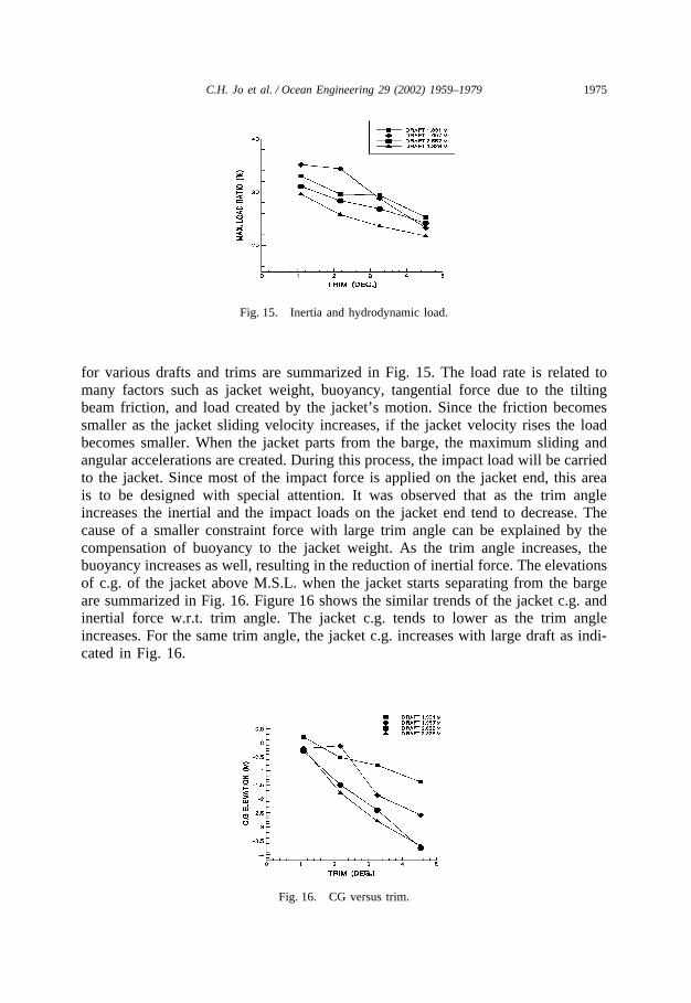
Fig. 15. Inertia and hydrodynamic load.
for various drafts and trims are summarized in Fig. 15. The load rate is related tomany factors such as jacket weight, buoyancy, tangential force due to the tiltingbeam friction, and load created by the jacket’s motion. Since the friction becomessmaller as the jacket sliding velocity increases, if the jacket velocity rises the loadbecomes smaller. When the jacket parts from the barge, the maximum sliding andangular accelerations are created. During this process, the impact load will be carriedto the jacket. Since most of the impact force is applied on the jacket end, this areais to be designed with special attention. It was observed that as the trim angleincreases the inertial and the impact loads on the jacket end tend to decrease. Thecause of a smaller constraint force with large trim angle can be explained by thecompensation of buoyancy to the jacket weight. As the trim angle increases, thebuoyancy increases as well, resulting in the reduction of inertial force. The elevationsof c.g. of the jacket above M.S.L. when the jacket starts separating from the bargeare summarized in Fig. 16. Figure 16 shows the similar trends of the jacket c.g. andinertial force w.r.t. trim angle. The jacket c.g. tends to lower as the trim angleincreases. For the same trim angle, the jacket c.g. increases with large draft as indi-cated in Fig. 16.
Fig. 16. CG versus trim.
1976 C.H. Jo et al. / Ocean Engineering 29 (2002) 1959–1979
Table 12Submerging depth — Case 1
Reserved buoyancy (%)17.98 14.05 10.66
Minimum Distance (m) 30.15 29.75 29.05Draft (m) and trim (°) 1.331/1.085 1.331/1.085 1.331/1.085
Maximum Distance (m) 30.79 29.90 29.24Draft (m) and trim (°) 1.331/4.335 2.951/1.085 2.951/1.085
Deviation (m) 0.64 0.15 0.19
Table 13Submerging depth — Case 2
Reserved buoyancy (%)17.94 14.72 10.66
Minimum Distance (m) 46.01 45.79 45.24Draft (m) and trim (°) 1.997/1.085 1.997/1.085 1.997/1.085
Maximum Distance (m) 49.98 48.79 48.01Draft (m) and trim (°) 1.997/4.335 2.085/1.085 2.085/1.085
Deviation (m) 3.97 3.00 2.77
5.4. Submerging depth
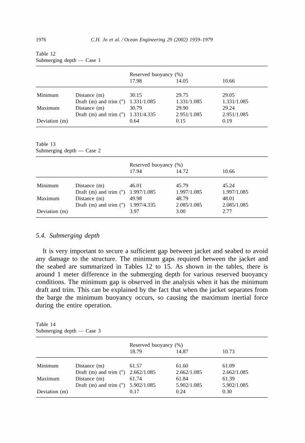
It is very important to secure a sufficient gap between jacket and seabed to avoidany damage to the structure. The minimum gaps required between the jacket andthe seabed are summarized in Tables 12 to 15. As shown in the tables, there isaround 1 meter difference in the submerging depth for various reserved buoyancyconditions. The minimum gap is observed in the analysis when it has the minimumdraft and trim. This can be explained by the fact that when the jacket separates fromthe barge the minimum buoyancy occurs, so causing the maximum inertial forceduring the entire operation.
Table 14Submerging depth — Case 3
Reserved buoyancy (%)18.79 14.87 10.73
Minimum Distance (m) 61.57 61.60 61.09Draft (m) and trim (°) 2.662/1.085 2.662/1.085 2.662/1.085
Maximum Distance (m) 61.74 61.84 61.39Draft (m) and trim (°) 5.902/1.085 5.902/1.085 5.902/1.085
Deviation (m) 0.17 0.24 0.30
1977C.H. Jo et al. / Ocean Engineering 29 (2002) 1959–1979
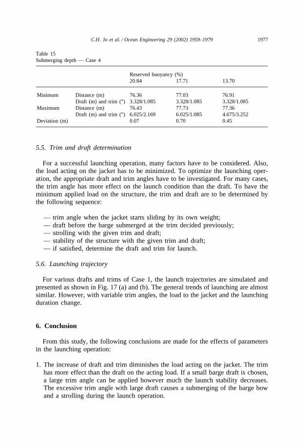
Table 15Submerging depth — Case 4
Reserved buoyancy (%)20.84 17.71 13.70
Minimum Distance (m) 76.36 77.03 76.91Draft (m) and trim (°) 3.328/1.085 3.328/1.085 3.328/1.085
Maximum Distance (m) 76.43 77.73 77.36Draft (m) and trim (°) 6.025/2.169 6.025/1.085 4.675/3.252
Deviation (m) 0.07 0.70 0.45
5.5. Trim and draft determination
For a successful launching operation, many factors have to be considered. Also,the load acting on the jacket has to be minimized. To optimize the launching oper-ation, the appropriate draft and trim angles have to be investigated. For many cases,the trim angle has more effect on the launch condition than the draft. To have theminimum applied load on the structure, the trim and draft are to be determined bythe following sequence:
— trim angle when the jacket starts sliding by its own weight;— draft before the barge submerged at the trim decided previously;— strolling with the given trim and draft;— stability of the structure with the given trim and draft;— if satisfied, determine the draft and trim for launch.
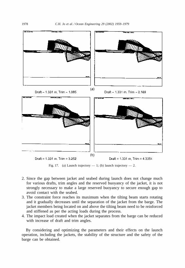
5.6. Launching trajectory
For various drafts and trims of Case 1, the launch trajectories are simulated andpresented as shown in Fig. 17 (a) and (b). The general trends of launching are almostsimilar. However, with variable trim angles, the load to the jacket and the launchingduration change.
6. Conclusion
From this study, the following conclusions are made for the effects of parametersin the launching operation:
1. The increase of draft and trim diminishes the load acting on the jacket. The trimhas more effect than the draft on the acting load. If a small barge draft is chosen,a large trim angle can be applied however much the launch stability decreases.The excessive trim angle with large draft causes a submerging of the barge bowand a strolling during the launch operation.
1978 C.H. Jo et al. / Ocean Engineering 29 (2002) 1959–1979
Fig. 17. (a) Launch trajectory — 1; (b) launch trajectory — 2.
2. Since the gap between jacket and seabed during launch does not change muchfor various drafts, trim angles and the reserved buoyancy of the jacket, it is notstrongly necessary to make a large reserved buoyancy to secure enough gap toavoid contact with the seabed.
3. The constraint force reaches its maximum when the tilting beam starts rotatingand it gradually decreases until the separation of the jacket from the barge. Thejacket members being located on and above the tilting beam need to be reinforcedand stiffened as per the acting loads during the process.
4. The impact load created when the jacket separates from the barge can be reducedwith increase of draft and trim angles.
By considering and optimizing the parameters and their effects on the launchoperation, including the jackets, the stability of the structure and the safety of thebarge can be obtained.
1979C.H. Jo et al. / Ocean Engineering 29 (2002) 1959–1979
References
API, 1993. Recommended Practice for Planning, Designing and Constructing Fixed Offshore Platforms’Working Stress Design, API (RP2A-WSD).
Chakrabarti, K.S., 1995. Scale effects on a unique launch sequence of a gravity-based structure. AppliedOcean research 17, 33–41.
Gerwick, B.C., 1986. Construction of Offshore Structures. John Wiley and Sons, Inc,KAIST-a, 1985. Development of Design Technology of Offshore Platforms for Offshore Oil Production.
Ministry of Korean Science and Technology, vol. 3, Jacket Structure Design.KAIST-b, 1985. Development of Design Technology of Offshore Platforms for Offshore Oil Production.
Ministry of Korean Science and Technology, vol. 6, Transportation and Installation.Lee, S.H., 2000. The Parametric Study for Offshore Structure Launching. Master thesis, Inha Univer-
sity, Korea.Noble, Denton and Associates Inc., 1984. Transportation and Installation of Offshore Jackets, Decks and
Modules, Section 12.Ultramarine Inc., 1999. SACS Program Manual.
Dr Chul H. Jo is an Associate Professor in the Department of Naval Architecture and Ocean Engineering atInha University, S. Korea. He received a Master of Engineering in Ocean Engineering from Steven Instituteof Technology in USA in 1985. In 1991 he has finished his Ph.D course in Ocean Engineering at Texas A&M University in USA After working for Intec Engineering Inc. and Hyundai Heavy Industries from 1991 to1997, he became a faculty member at Inha University in South Korea.