Parametric analysis of the effect of scattered light upon ... · ric plots provide the optical...
13
Parametric analysis of the effect of scattered light upon the modulation transfer function James E. Harvey Downloaded From: http://opticalengineering.spiedigitallibrary.org/ on 07/29/2013 Terms of Use: http://spiedl.org/terms
Transcript of Parametric analysis of the effect of scattered light upon ... · ric plots provide the optical...

Parametric analysis of the effect ofscattered light upon the modulationtransfer function
James E. Harvey
Downloaded From: http://opticalengineering.spiedigitallibrary.org/ on 07/29/2013 Terms of Use: http://spiedl.org/terms

Parametric analysis of the effect of scattered light uponthe modulation transfer function
James E. HarveyPhoton EngineeringLLC, 440 S. Williams BoulevardSuite 106 Tucson, Arizona 85711E-mail: [email protected]
Abstract. The modulation transfer function (MTF) is widely used as theimage quality criterion of choice for imaging applications where fine detailin extended images needs to be specified or evaluated. We present aparametric analysis of the effect of scattered light upon the MTF of an im-aging system and illustrate the results for three specific applications: (1) avisible Newtonian telescope with moderately good optical surfaces whichproduce no significant effect upon the MTF, (2) an extreme ultravioletNewtonian telescope where scattering effects can dominate both diffrac-tion effects and aberrations in the resulting image degradation even forstate-of-the-art optical surfaces, and (3) a visible system made up ofthree diamond-turned off-axis aspheric mirrors where we use the predictedMTF to estimate whether post-polishing is required (huge cost and sched-ule impact) to meet a specific image quality requirement. © 2013 Society ofPhoto-Optical Instrumentation Engineers (SPIE) [DOI: 10.1117/1.OE.52.7.073110]
Subject terms: modulation transfer function due to surface scatter; modulation trans-fer function; image degradation.
Paper 130568 received Apr. 15, 2013; revised manuscript received Jun. 24, 2013;accepted for publication Jun. 25, 2013; published online Jul. 29, 2013.
1 IntroductionThe modulation transfer function (MTF) is widely used asthe image quality criterion of choice for imaging applicationswhere fine detail in extended images needs to be specified orevaluated.1–3 This is particularly true for imaging systemsdegraded by diffraction effects and geometrical aberrations.However, there seems to be a dearth of optical engineeringliterature concerning the effects of scattered light upon theMTF. Exceptions include the medical x-ray imaging commu-nity involved in projection mammography4 and the visioncommunity where intraocular scattering effects are ofconcern.5
In this article, we present a detailed parametric analysis ofthe effect of scattered light from residual optical fabricationerrors upon the MTF of an imaging system. After a brief his-torical background of surface scatter theory, we review theevolution of a linear systems formulation of surface scattertheory that characterizes the surface scatter behavior by asurface transfer function (STF). This STF can merely bemultiplied by the classical optical transfer function (OTF)characterizing image degradation by diffraction effects andgeometrical aberrations to obtain the composite MTF for sys-tems also degraded by surface scatter effects. Insight into themagnitude of image degradation due to surface scatter is thenprovided by performing a detailed parametric analysis ofMTF behavior for surfaces with a Gaussian surface powerspectral density (PSD) function. The parameters variedinclude the surface-roughness-to-wavelength ratio, surfacecorrelation width, and incident angle. The resulting paramet-ric plots provide the optical engineer with insight and under-standing concerning the relative importance of diffractionand scattering that is not readily available in the currentlyexisting literature.
This analysis is first applied to a Newtonian telescopewith moderately good mirrors operating at visible wave-lengths. The resulting image degradation due to scatteredlight is barely perceptible. We then apply the analysis to thesame Newtonian telescope with state-of-the-art mirror surfa-ces operating at extreme ultraviolet (EUV) wavelengthsranging from 300 to 100 Å. At the long wavelength endof this spectral range diffraction effects dominate the scattereffects; however, at the shortest wavelengths, surface scattereffects dominate the diffraction. A third application involvesa system made up of three diamond-turned off-axis asphericmirrors operating at a wavelength of 600 nm in the visible.We demonstrate how the predicted MTF can be used to esti-mate whether post-polishing will be required to meet a spe-cific image quality requirement.
Finally, we briefly discuss how to use commercially avail-able state-of-the-art optical analysis software to calculate theMTF degradation due to stray light from bulk or particulatescatter provided either measured or assumed bidirectionalreflectance distribution function (BRDF) data is available.
2 Historical Background of Surface Scatter TheoryScattering effects from microtopographic surface roughnessare merely nonparaxial diffraction phenomena resultingfrom random phase variations in the reflected wavefront.Rayleigh–Rice6–8 or Beckmann–Kirchhoff9 theories arecommonly used to predict surface scatter effects. Also,Harvey and Shack (1976) developed a linear systems formu-lation of surface scatter phenomena in which the scatteringbehavior is characterized by a STF.10,11 This treatment pro-vided insight and understanding not readily gleaned from thetwo previous theories. However, smooth surface and/or para-xial approximations have severely limited the range of appli-cability in each of the above theoretical treatments.
The Rayleigh–Rice vector perturbation theory agrees wellwith experimental wide-angle scatter measurements from“smooth” (4πσrel cos θi∕λ ≪ 1) surfaces for arbitrary0091-3286/2013/$25.00 © 2013 SPIE
Optical Engineering 073110-1 July 2013/Vol. 52(7)
Optical Engineering 52(7), 073110 (July 2013)
Downloaded From: http://opticalengineering.spiedigitallibrary.org/ on 07/29/2013 Terms of Use: http://spiedl.org/terms

incident and scattering angles. However, not all applicationsof interest satisfy the smooth surface approximation. TheBeckmann–Kirchhoff scattering theory is valid for roughersurfaces; but it contains a paraxial (small angle) assumptionthat limits its ability to accurately handle wide-angle scatter-ing and large angles of incidence. The two most widely usedsurface scattering theories are thus complementary but notall-inclusive; i.e., neither of them, nor the combination ofthem, adequately describes scattering behavior for moder-ately rough surfaces with a large incident and scatteringangles.
The original Harvey–Shack (OHS) surface scatter theoryhas, essentially, the same limitations as the Beckmann–Kirchhoff theory. This transfer function characterization ofscattering surfaces was modified in the 1980s to includegrazing-incidence effects in x-ray telescopes; however, itwas still limited to small-angle scattering.12
In 2004, Elfouhaily and Guerin conducted a critical sur-vey of approximate scattering wave theories from randomrough surfaces.13 They attempted to classify and characterize>30 different approximate methods. These were all variantsof the small perturbation method (Rayleigh–Rice), theKirchhoff approach, or so-called unified methods whichtried to bridge the gap between the two. This exhaustive sur-vey included 260 references. They concluded that “theredoes not seem to be a universal method that is to be preferredsystematically. All methods present a compromise betweenversatility, simplicity, numerical efficiency, accuracy androbustness.” Their final statement was, “There is stillroom for improvement in the development of approximatescattering methods.”
In 1998, an empirical modification of the Beckmann–Kirchhoff surface scatter theory was developed that appearedto satisfactorily combine the advantages of both theRayleigh–Rice and the Beckmann–Kirchhoff theorieswithout the disadvantages of either.14 However, because itwas empirically developed rather than theoretically derived,this work was not published in the archival literatureuntil 2007.15 During this time interval, the modifiedBeckmann–Kirchhoff surface scatter model was evaluated,implemented, and referenced by researchers in the computervision and computer animation fields who are less interestedin rigorously solving the surface scatter problem than merelyhaving a surface scatter model that results in the rendering ofrealistic surfaces, textures, objects, and scenes under a widevariety of illumination conditions.16–24
A new linear systems formulation of nonparaxial scalardiffraction theory25,26 applied to surface scatter phenomenaeventually resulted in a generalized Harvey–Shack (GHS)surface scatter theory that produces accurate results forrougher surfaces than the Rayleigh–Rice theory and forlarger incident and scattered angles than the classicalBeckmann–Kirchhoff theory.27,28
3 Transfer Function Characterization of ScatteringSurfaces
The well-known linear systems formulation of image forma-tion is illustrated schematically in Fig. 1. The irradiance dis-tribution in the image of a point source, or point spreadfunction (PSF), of the imaging system is given by thesquared modulus of the Fourier transform of the complexpupil function. From the autocorrelation theorem of Fourier
transform theory, the PSF is also given by the Fourier trans-form of the autocorrelation of the complex pupil function.The OTF is defined as the (normalized) autocorrelation ofthe complex pupil function. The OTF and the PSF thus con-stitute a Fourier transform pair. A variety of commonly usedimage quality criteria are also added to the diagram, indicat-ing from which function they are most readily obtained.
The imaging system must be isoplanatic (or shift invari-ant) if a given OTF is going to completely characterize thesystem. If any field-dependent aberrations are present, a sep-arate OTF is required for each field angle.
Figure 2 schematically illustrates the statistical surfacecharacteristics in a very reminiscent manner of the diagramin Fig. 1. Note that the surface autocovariance (ACV) func-tion and the surface PSD function constitute a Fourier trans-form pair.
One can now formulate a linear systems theory of surfacescatter phenomena by deriving an analytic expression for aSTF in much the same way that the OTF was derived inimage formation theory.10,27,28
3.1 OHS Surface Scatter Theory
In the OHS surface scatter theory, paraxial assumptions weremade that resulted in the following simple expression for theSTF.10,11
Hsðx; yÞ ¼ expf−ð4πσsÞ2½1 − Csðx; yÞ∕σ2s �g; (1)
where σs is the rms surface roughness and Csðx; yÞ is thesurface ACV function. The scattered light distribution, calledan angle spread function (ASF) in analogy with the PSF of
Fig. 1 Schematic diagram of the linear systems formulation of imageformation theory.
Fig. 2 Schematic diagram of the statistical surface characteristics.
Optical Engineering 073110-2 July 2013/Vol. 52(7)
Harvey: Parametric analysis of the effect of scattered light upon the modulation transfer function
Downloaded From: http://opticalengineering.spiedigitallibrary.org/ on 07/29/2013 Terms of Use: http://spiedl.org/terms

imaging systems, is given by the Fourier transform ofthis STF.
The STF can also be written in the form
Hðx; yÞ ¼ Aþ BGðx; yÞ (2)
where
A ¼ exp½−ð4πσsÞ2�; (3)
and
B ¼ 1 − exp½−ð4πσsÞ2� (4)
are the fraction of the total reflected radiant power containedin the specular and the scattered components, respectively,and
Gðx; yÞ ¼ exp½ð4πÞ2Csðx; yÞ� − 1
exp ð4πσsÞ2 − 1: (5)
From Eq. (2), we see that the STF can be written as thesum of two separate components. The ASF can therefore beexpressed as the sum of the Fourier transforms of the twocomponents making up the STF:
ASFðα; βÞ ¼ FfHðx; yÞg ¼ Aδðα; βÞ þ Sðα; βÞ; (6)
where the scattering function, Sðα; βÞ, is given by
Sðα; βÞ ¼ BF ½Gðx; yÞ�: (7)
Note that a scaled coordinate system has been used inwhich the spatial variables are normalized by the wavelengthof the light (x ¼ x∕λ, y ¼ y∕λ, etc.). The reciprocal variablesα and β are thus the direction cosines of the propagation vec-tors of the angular spectrum of plane waves discussed byGoodman,29 Gaskill,30 and Ratcliff.31 These directioncosines α, β, and γ are related to the angular variables θand ϕ in conventional spherical coordinates by the followingexpressions32:
α ¼ sin θ cos ϕ; β ¼ sin θ sin ϕ; γ ¼ cos θ: (8)
It is only in this direction cosine space that diffraction(and surface scatter) phenomena exhibit shift-invariantbehavior with changes in incident angle, and the radiometricquantity that exhibits this behavior is the diffracted (or scat-tered) radiance, not intensity or irradiance.25,33
Figure 3 graphically illustrates the form of this STF andits associated ASF. The STF is made up of a constant A plus abell-shaped component of height B. These two componentstransform into a delta function and a scattering function,respectively. The scattering surface therefore reflects an inci-dent beam of light as a specularly reflected beam (the deltafunction) of diminished intensity surrounded by a halo ofscattered light. From the central ordinate theorem ofFourier transform theory, the volume under the scatteringfunction is equal to B, but Aþ B ¼ 1, hence B is equalto a quantity widely referred to as the total integrated scatter(TIS).34
The ASF and the corresponding scattering function arescattered radiance functions, which are consistent with thefact that the BRDF was defined by Nicodemus in 1970 as
the reflected (or scattered) radiance divided by the incidentirradiance:35
BRDF ¼ fðθs;φs; θi;φiÞ ¼dLðθs;φs; θi;φiÞ
dEðθi;φiÞ: (9)
Although there was no explicit smooth surface approxi-mation in this OHS surface scatter theory, the derivation ofEq. (1) did suffer from the same paraxial limitations as theclassical Beckmann–Kirchhoff theory. However, for a broadclass of scattering surfaces, including optical surfacespolished with conventional techniques on ordinary glassyamorphous materials, the ASF exhibits near shift-invariantbehavior in direction cosine space with respect to the inci-dent angle.11 This led to a modest following among the radio-metric community of BRDF curves plotted in the Harvey-Shack β − βo format. Breault made an extensive use ofthis format in building a catalog of BRDF data from variousmaterials and surfaces for use in his APART baffle designprogram.36 Today the ASAP, FRED, Trace-Pro, andZEMAX codes all use some form of the Harvey-ShackBRDF model.37–40
Also, if one does make the smooth surface approximation,the quantity Gðx; yÞ reduces to the normalized surface ACVfunction, Csðx; yÞ∕σ2s , and the scattering function becomesproportional to the surface PSD function as predicted bythe classical Rayleigh–Rice theory.6–8
3.2 Modified Harvey-Shack Surface Scatter Theory
The above transfer function characterization of scatteringsurfaces was modified in the 1980s to include grazing inci-dence effects in X-ray telescopes, and “mid” spatial fre-quency surface errors that span the gap between “figure”and “finish” errors.12 This allowed an understanding ofimage degradation due to scattering effects from residualoptical fabrication errors on NASA’s Chandra Observatoryand NOAA’s Solar X-ray Imager.41,42
Krywonos has shown that the STF for an arbitrary inci-dent angle (assuming small angle scattering) can beexpressed as27,28
Hsðx; y; γiÞ ¼ expf−ð4πγiσrelÞ2½1 − Csðx; yÞ∕σ2s �g: (10)
This can again be written in the form
Hsðx; y; γiÞ ¼ AðγiÞ þ BðγiÞGðx; y; γiÞ; (11)
Fig. 3 Illustration of the surface transfer function (STF) and the anglespread function of a scattering surface.
Optical Engineering 073110-3 July 2013/Vol. 52(7)
Harvey: Parametric analysis of the effect of scattered light upon the modulation transfer function
Downloaded From: http://opticalengineering.spiedigitallibrary.org/ on 07/29/2013 Terms of Use: http://spiedl.org/terms

where
AðγiÞ ¼ exp½−ð4πγiσrelÞ2�; BðγiÞ ¼ 1 − exp½−ð4πγiσrelÞ2�;(12)
and
Gðx; y; γiÞ ¼exp½ð4πγiÞ2Csðx; yÞ� − 1
exp½ð4πγiσrelÞ2� − 1: (13)
In Eq. (10), we have used the relevant surface roughness,σrel, since spatial frequencies lying outside of the band-lim-ited portion of the surface PSD do not contribute to the scat-tered radiation.28 The surface ACV function is divided by thetotal, or intrinsic, rms roughness, σs, as its purpose is to nor-malize the height of the surface ACV function to unity.
Awavefront incident on the scattering surface at an angleθi is equivalent to introducing a linear phase variation acrossthe pupil. Assuming the plane of incidence to be the y-zplane, this will cause a shift of the scattering function indirection cosine space of β − βo, where β ¼ sin θ andβo ¼ sin θo. The ASF is therefore given by the Fourier trans-form of the STF in Eq. (10), or Eq. (11), multiplied by thelinear phase variation:
ASFðα;β−βo;γiÞ¼FfHsðx;y;γiÞexpð−i2πyβoÞg¼AðγiÞδðα;β−βoÞþSðα;β−βo;γiÞ; (14)
where
Sðα; β − βo; γiÞ ¼ BðγiÞFfGðx; y; γiÞ expð−i2πyβoÞg and
βo − βi: (15)
This is again the sum of a delta function at the location ofthe specular direction surrounded by a scattering function, S,where the fraction of the total reflected power in the specularbeam is given by AðγiÞ, and the fraction of total reflectedpower in the scattering function (TIS) is given by BðγiÞ.Hence, AðγiÞ þ BðγiÞ ¼ 1, and the ASF again has unitvolume.
If any portion of the scattering function S in Eq. (15) fallsoutside of the unit circle in direction cosine space, it willneed to be truncated and renormalized as dictated byParseval’s theorem (also assures conservation of energy).This is accomplished in the same manner as was done fordiffraction in Sec. 2 of Ref. 25. The renormalization con-stant, K, for the scattering function is given by
KðγiÞ ¼ BðγiÞ�Z
1
α¼−1
Z ffiffiffiffiffiffiffiffi1−α2
p
β¼−ffiffiffiffiffiffiffiffi1−α2
p Sðα; β − βo; γiÞdαdβ�−1
;
(16)
and only differs from unity for large incident and scatteredangles where the scattering radiance distribution functionextends beyond the unit circle in direction cosine space(i.e., only if evanescent waves are produced).25 The renor-malized ASF is thus given by
ASF 0ðα; β − βo; γiÞ ¼ KðγiÞFfHsðx; y; γiÞ expð−i2πβoyÞg:(17)
Recall that the ASF is a radiance function of unit volume.We can convert the ASF to radiant intensity by multiplying it
by the total reflected radiant power and the Lambert’s cosinefunction
Iðα; β − βo; γiÞ ¼ RPiASF0ðα; β − βo; γiÞ cos θs: (18)
Clearly, the surface scatter process is no longer strictlyshift invariant with respect to incident angle as reported inRefs. 10 and 11 since Eq. (10) can be interpreted as a one-parameter family of STFs; i.e., a different STF is required foreach incident angle. This is analogous to imaging in the pres-ence of field-dependent aberrations, where a different OTF isrequired for each field angle.
3.3 GHS Surface Scatter Theory
The modified version of the Harvey–Shack theory wasshown to be a significant improvement over the OHS theoryin Ref. 28, especially for large incident angles. However, therestriction of small scattering angles is still very limiting.Furthermore, the OHS and MHS scattering theories wererestricted to mirror surfaces and did not include the moregeneral situation of scattering from a random rough surfacebetween two media with arbitrary refractive indices.43
Again Krywonos has shown that the following two-parameter family of STFs is required to characterize the scat-tering process for arbitrary incident and scattering angles:28
Hsðx; y; γi; γsÞ ¼ expf−½2πσrelðn1γi∓n2γsÞ�2× ½1 − Csðx; yÞ∕σ2s �g: (19)
This general expression for the STF may be used to modeleither reflective or transmissive surface scatter; however, thediscussion in this article will be restricted to applications ofscattering from mirror surfaces, i.e., n2 ¼ −n1. If the mirroris immersed in air (or vacuum), n1 ¼ 1 and Eq. (19) can bewritten as
Hsðx; y; γi; γsÞ ¼ expf−½2πσrelðγi þ γsÞ�2× ½1 − Csðx; yÞ∕σ2s �g: (20)
Once again, the STF can be written in the form
Hsðx; y; γi; γsÞ ¼ Aðγi; γsÞ þ Bðγi; γsÞGðx; y; γi; γsÞ; (21)
Aðγi; γsÞ ¼ expf−½2πðγi þ γsÞσrel�2g; (22)
where
Bðγi; γsÞ ¼ 1 − expf−½2πðγi þ γsÞσrel�2g; (23)
Gðx; y;γi;γsÞ¼exp
�½2πðγiþγsÞ�2 σ
2rel
σ2sCsðx; yÞ
�−1
exp ½2πðγiþγsÞσrel�2−1: (24)
The ASF can thus still be written as the sum of a shifted δfunction (specularly reflected beam) and an associated scat-tering function Sðα; β − βoÞ:ASFðαs; βs; γi; γsÞ ¼ ½Aðγi; γsÞδðα; β − βoÞ
þ Sðα; β; γi; γsÞ�jα¼αs;β¼βs; (25)
Optical Engineering 073110-4 July 2013/Vol. 52(7)
Harvey: Parametric analysis of the effect of scattered light upon the modulation transfer function
Downloaded From: http://opticalengineering.spiedigitallibrary.org/ on 07/29/2013 Terms of Use: http://spiedl.org/terms

where
Sðα; β; γi; γsÞ ¼ Bðγi; γsÞFfGðx; y; γi; γsÞ expð−i2πβoyÞg:(26)
When numerical solutions of Eq. (26) are required, theparameters γs and γi have to be specified before performingthe Fourier transform. Calculating the scattering distributionover the entire observation space for a given angle of inci-dence will therefore require a different STF and Fouriertransform calculation for every scattering angle.
4 System MTF in the Presence of Surface ScatterThe linear systems formulation of surface scatter phenomenadiscussed in Sec. 3 not only provides insight and understand-ing concerning a topic often perceived as being nonintuitiveand complicated but also suggests that the image degradationdue to the combined effects of diffraction, aberrations, andscattered light can be obtained by merely multiplying theSTF by the classical MTF characterizing the image degrada-tion due to diffraction and aberrations. However, there hasbeen legitimate skepticism concerning the accuracy of thissimple solution.44 A few comments are thus in order to jus-tify this simple cascading of transfer functions.
From linear systems theory, we learned that that the trans-fer functions characterizing various subsystems (or physicalprocesses) can merely be multiplied to obtain the systemtransfer function if and only if the subsystems (or individualphysical processes) are independent and uncorrelated. Fromthe convolution theorem of Fourier transform theory, multi-plying transfer functions is equivalent to convolving impulseresponses (PSFs in optical imaging applications).
Boreman discusses several MTF contributors in additionto diffraction and aberrations: detector MTF, motion MTF,vibration MTF, turbulence MTF, aerosol MTF, etc.2 Hethen discussed cascading (multiplying) MTFs in consider-able detail, giving examples where cascading MTFs will pro-vide accurate results as well as examples where cascadingMTFs give completely inaccurate results.
It always comes back to whether the various errors (orimage degradation mechanisms) are independent and uncor-related. An additional example is the image degradation dueto residual design errors and alignment errors in a telescope.Can we merely convolve the degraded PSF due to theresidual design errors with the degraded PSF due to the mis-alignment errors? Definitely not if the error in both cases iscoma. Because they are not uncorrelated. The coma due toresidual design errors can actually balance, or partially can-cel, the coma due to alignment errors.
Our experience with regard to image degradation due todiffraction, geometrical aberrations, and surface scatter dueto residual optical fabrication errors has been “yes” the aerialimage of a point source in the focal plane of the telescope isaccurately given by the aperture diffraction PSF convolvedby the geometrical PSF convolved by the surface scatterPSF.45 However, since the phase variations induced uponthe reflected wavefront by surface roughness are very similarin nature to classical wavefront aberrations, one needs toapply some caution regarding where one draws the line onthe surface PSD function between the low spatial frequencyfigure errors that produce classical aberrations and the highspatial frequency surface roughness that produces scatteredlight. It is rather arbitrary, but probably safe, to consider this
dividing line such that wavefront errors lower than the 22nd,or the 36th, Zernike polynomial is included in the low spatialfrequency figure errors (deterministic) and to include thehigher Zernike terms with the (statistical) mid or high spatialfrequency surface roughness that produces scattered light.
Finally, in a recent publication by Choi and Harvey,46 ithas been shown that, for multielement imaging systemsdegraded by both surface scatter and aberrations, thecomposite PSF is obtained in explicit analytic form interms of convolutions of the geometrical PSF and scaledBRDFs of the individual surfaces of the imaging system. Theapproximations and assumptions in this formulation are dis-cussed, and the result is compared to the irradiance distribu-tion obtained using commercial software for the case of atwo-mirror telescope operating at EUV wavelength. Thetwo results are virtually identical.
We thus proceed by stating with some confidence that theproduct of the STF with the classical MTF of an imagingsystem will comprise the system MTF in the presence of sur-face scatter. Assuming an imaging system with a circularaperture (D ¼ 50 mm, f ¼ 200 mm) operating at λ ¼0.5 μm, the diffraction-limited MTF is given by:47
MTF ¼ ðD2∕2Þfcos−1ðr∕DÞ − ðr∕DÞ½1 − ðr∕DÞ2�1∕2gπD2∕4
;
(27)
and has a cut-off spatial frequency ξc ¼ D∕λf ¼ 500 mm−1
as shown in Fig. 4.Assume also that there is a single reflecting surface with a
Gaussian ACV function that produces a TIS ¼ 0.2 (corre-sponds to an rms roughness of σ ¼ 188 Å)
ACV2DðrÞ ¼ Csðx; yÞ ¼ σ2Gauss
�r
l
�
¼ σ2 exp
�−π
�r
l
�2�;
l ¼ 2:0 mm:
(28)
For smooth surfaces, the STF is given by
STF ¼ Aþ BGðx; yÞ ≈ Aþ BCsðx; yÞ∕σ2 (29)
Fig. 4 Diffraction-limited modulation transfer function (MTF) of imag-ing system with a circular aperture.
Optical Engineering 073110-5 July 2013/Vol. 52(7)
Harvey: Parametric analysis of the effect of scattered light upon the modulation transfer function
Downloaded From: http://opticalengineering.spiedigitallibrary.org/ on 07/29/2013 Terms of Use: http://spiedl.org/terms

STF ≈ 0.8þ 0.2Gauss
�r
l
�����r¼ρλf
¼ 0:8þ 0:2 exp
�−π
�ρ
l∕λf
�2�
(30)
and illustrated graphically in Fig. 5. We have increased thesurface correlation width substantially beyond what it wouldtypically be to enable seeing the nature of the STF at smallspatial frequencies.
The system transfer function is given by the product of theclassical MTF and the STF
Hðx; yÞsys ¼ MTF × STF: (31)
As illustrated in Fig. 6, the system transfer function, asdegraded by wide-angle scatter from high spatial frequencymicroroughness, drops very quickly (at a spatial frequency ofabout l∕λf) to a value of 1-TIS, then continues diminishedproportionately from the classical MTF by that amount
Hðx; yÞsys ¼ ð1 − TISÞMTF for ξ > l∕λf: (32)
The classical definition of TIS is that fraction of the totalreflected radiant power that is scattered out of the specularlyreflected beam. Following Davies48 and Bennett andPorteus,49 the TIS due to surface scatter from a single mod-erately rough surface is given by the following analyticalexpression
TIS ¼ 1 − exp½−ð4π cos θiσrel∕λÞ2�: (33)
The above definition of TIS and its paraxial smooth sur-face approximation
TIS ≈ ð4πσrel∕λÞ2 (34)
has been discussed extensively in the literature, most recentlyin Ref. 34. We want to emphasize that the approximateexpression in Eq. (34) can only be used for very smooth sur-faces. Figure 7 illustrates that the error in Eq. (34) increasesexponentially if the rms roughness of the surface exceeds avalue of approximately σrel ¼ 0.03λ:
Note also that the above expressions for TIS involve theband-limited relative roughness mentioned earlier inSecs. 3.2 and 3.3. This relative roughness and how to
calculate it from metrology data are also discussed in detailin Ref. 34.
5 Parametric Analysis of MTF Behavior forGaussian Surface PSDs
Since approximations and assumptions were made in theabove analysis, we will now provide a parametric analysisof the effect of scatter upon the MTF for surfaces withGaussian surface PSDs. This parametric analysis will pro-vide insight concerning when one can use the smooth-sur-face approximation of the OHS surface scatter theory andwhen one must progress to the MHS or the GHS theory.
5.1 Variations in Surface Roughness (and TIS)
Keeping the same optical design parameters (D ¼ 50 mm,f ¼ 200 mm), and a Gaussian surface ACV function, wewill now calculate, and illustrate graphically, variations inSTF behavior as we increase the surface roughness (andtherefore the amount of light scattered). We have increasedthe surface ACV length, l ¼ 8.0 mm, to enable us to moreeasily see the differences on our parametric plots.
Figure 8 illustrates the STF predicted by the OHS theoryEqs. (1–5) and the smooth-surface approximation to theOHS theory in which Gðx; yÞ ¼ Csðx; yÞ∕σ2s for increasing
Fig. 5 STF for above example.
Fig. 6 Illustration of the effect of surface scatter upon the MTF of animaging system.
Fig. 7 Illustration of the growth of total integrated scatter (TIS) withincreasing surface roughness for normal incidence. Note the expo-nentially increasing error in Eq. (34) when σrel > 0.02λ.
Optical Engineering 073110-6 July 2013/Vol. 52(7)
Harvey: Parametric analysis of the effect of scattered light upon the modulation transfer function
Downloaded From: http://opticalengineering.spiedigitallibrary.org/ on 07/29/2013 Terms of Use: http://spiedl.org/terms
values of surface roughness that results in values of TIS rang-ing from 0.016 to 0.80. Note that for normal incidence and aGaussian surface PSD, the smooth-surface approximation tothe OHS expression for the STF does not introduce a signifi-cant error until TIS > 0.2 and then only for spatial frequen-cies ξ < l∕λf.
Common image quality criteria might be to specify themaximum allowable degradation due to scatter in the valueof the MTF at a specific spatial frequency or to specify themaximum allowable decrease in spatial frequency (due toscatter) at which a specified modulation is maintained.Figure 9 illustrates the composite MTF due to both scatterand diffraction indicating that for a TIS ¼ 0.2, there is an18% decrease in the modulation at a spatial frequencyequal to one-half the cut-off spatial frequency and a 24%decrease in the spatial frequency at which a modulationof 0.5 is maintained.
5.2 Variations in Surface ACV Width
We have observed a 20% drop in the MTF caused by surfaceroughness (σ ¼ 188 Å) sufficient to produce TIS ¼ 0.2. Therate at which the MTF drops is determined by the width ofthe Gaussian surface ACV function. Figure 10 illustrates thisvariation in MTF behavior with surface ACV width. Notethat l does not significantly affect the MTF except at thevery short spatial frequencies.
5.3 Variations in Incident Angle
The modified Harvey–Shack (MHS) surface scatter theoryincludes the effect of incident angle upon the STF.Figure 11 graphically illustrates the difference in the STFpredicted by the OHS theory in which the single STFexpressed by Eq. (2) characterizes the scattering process, andthe MHS theory which requires a separate STF for each inci-dent angle as expressed in Eq. (10). Parametric plots are pre-sented for several increasingly large incident angles.
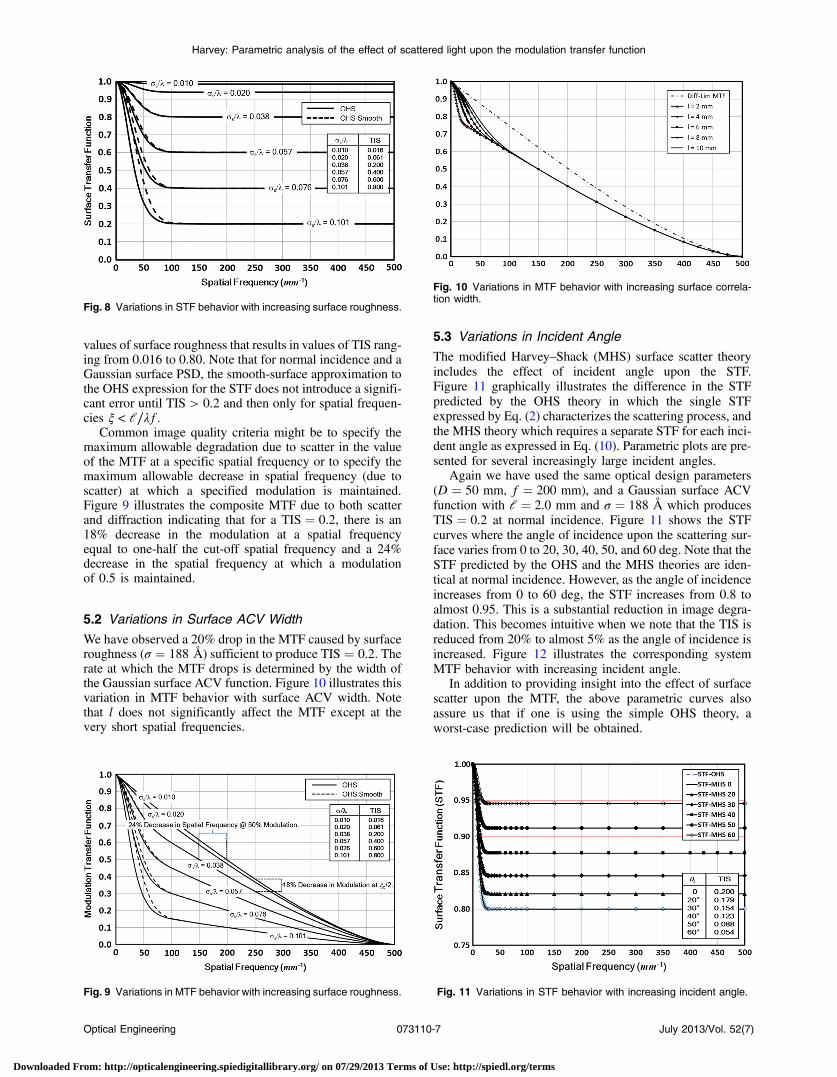
Again we have used the same optical design parameters(D ¼ 50 mm, f ¼ 200 mm), and a Gaussian surface ACVfunction with l ¼ 2.0 mm and σ ¼ 188 Å which producesTIS ¼ 0.2 at normal incidence. Figure 11 shows the STFcurves where the angle of incidence upon the scattering sur-face varies from 0 to 20, 30, 40, 50, and 60 deg. Note that theSTF predicted by the OHS and the MHS theories are iden-tical at normal incidence. However, as the angle of incidenceincreases from 0 to 60 deg, the STF increases from 0.8 toalmost 0.95. This is a substantial reduction in image degra-dation. This becomes intuitive when we note that the TIS isreduced from 20% to almost 5% as the angle of incidence isincreased. Figure 12 illustrates the corresponding systemMTF behavior with increasing incident angle.
In addition to providing insight into the effect of surfacescatter upon the MTF, the above parametric curves alsoassure us that if one is using the simple OHS theory, aworst-case prediction will be obtained.
Fig. 8 Variations in STF behavior with increasing surface roughness.
Fig. 9 Variations in MTF behavior with increasing surface roughness.
Fig. 10 Variations in MTF behavior with increasing surface correla-tion width.
Fig. 11 Variations in STF behavior with increasing incident angle.
Optical Engineering 073110-7 July 2013/Vol. 52(7)
Harvey: Parametric analysis of the effect of scattered light upon the modulation transfer function
Downloaded From: http://opticalengineering.spiedigitallibrary.org/ on 07/29/2013 Terms of Use: http://spiedl.org/terms
6 Applications Providing Insight into the MTFBehavior Degraded by Surface Scatter
At visible and infrared wavelengths, image degradation dueto light scattered from conventionally polished optical surfa-ces is minimal. However, as the operating wavelengthdecreases, diffraction effects diminish and image degradationdue to surface scatter from residual optical fabrication errorsincreases dramatically. Also, even at visible wavelengths,significant degradation of the MTF can occur for multiele-ment systems fabricated by unconventional optical fabrica-tion processes, such as diamond-turned metal surfaces. Wewill thus calculate and illustrate the results for three specificapplications: (i) a visible Newtonian telescope with moder-ately good optical surfaces, (ii) the same Newtonian tele-scope with state-of-the-art optical surfaces operating atEUV wavelengths, and (iii) a visible (λ ¼ 0.6 μm) systemmade up of three diamond-turned off-axis aspheric mirrorswhere we use the predicted MTF to estimate whetherpost-polishing will be required to meet a specific image qual-ity requirement.
6.1 Surface Scatter Effects upon the MTF of aVisible Newtonian Telescope
Figure 13 shows the effect of a central obscuration upon thenormalized diffraction-limited MTF of a two-mirror tele-scope.47 Note that there is a substantial decrease in the modu-lation at the mid spatial frequencies and a slight increase inthe modulation at the high spatial frequencies for annualapertures, with these effects being more pronounced forhigher obscuration ratios.
Let the telescope diameter, D, focal length, f, and obscu-ration ratio, ε, of the telescope be given by
D ¼ 50 mm; f ¼ 500 mm and ε ¼ 0.25: (35)
The cut-off spatial frequency in the MTF of an annularaperture is given by ξc ¼ D∕λf. Figure 14 illustrates the dif-fraction-limited MTF of our Newtonian telescope with anobscuration ratio of 0.25 for wavelengths of 7000, 6000,5000, and 4000 Å in the visible spectrum. Since the
Newtonian telescope provides a perfect geometrical imageon-axis, we have no image degradation due to aberrations.
We will assume that the primary mirror has a Gaussiansurface ACV function with an rms roughness, σs, and a cor-relation width, l, given by
σs ¼ 30 Å; l ¼ 1:0 mm (36)
and ignore any scattering due to the small plane folding sec-ondary mirror.
Even this rather relaxed rms roughness specification of30 Å on the surface of the primary mirror results in avalue of >0.99 for the constant plateau of the STF for allwavelengths >4000 Å as illustrated in Fig. 15. The valueof the TIS is also tabulated in Fig. 15 for four wavelengthsspanning the visible spectrum.
Multiplying the diffraction-limited MTF illustrated inFig. 14 by the STF shown in Fig. 15 shows that the degra-dation of the composite MTF due to surface scatter is barelyperceptible even for the shortest visible wavelength as shownin Fig. 16.
Fig. 12 Variations in composite MTF behavior with increasing inci-dent angle.
Fig. 13 Effect of the central obscuration upon the diffraction-limitedMTF of an annular aperture.
Fig. 14 Effect of wavelength upon the cut-off spatial frequency of thediffraction-limited MTF.
Optical Engineering 073110-8 July 2013/Vol. 52(7)
Harvey: Parametric analysis of the effect of scattered light upon the modulation transfer function
Downloaded From: http://opticalengineering.spiedigitallibrary.org/ on 07/29/2013 Terms of Use: http://spiedl.org/terms

6.2 Surface Scatter Effects upon the MTF of an EUVNewtonian Telescope
At EUV wavelengths, surface scatter effects can dominateboth diffraction effects and geometrical aberrations. TheNOAA Solar Ultra Violet Imager (SUVI) program for study-ing space weather effects due to geomagnetic storms on thesurface of the sun is an example where surface scatter effectsare of prime importance.50,51
Using the same Newtonian telescope as in the previousexample, Fig. 17 illustrates the diffraction-limited MTFfor wavelengths of 300, 250, 200, 170, 130, and 100 Å inthe EUV spectrum. Note the extremely large cut-off spatialfrequencies which scale inversely with the wavelength. Sincethe Newtonian telescope provides a perfect geometricalimage on-axis, we are still ignoring image degradation dueto aberrations.
Tightening the rms roughness specification to 8 Å andmaintaining the 1.0-mm correlation length on the primarymirror of the Newtonian telescope results in a STF at thesix different EUV wavelengths as shown in Fig. 18. Notethat the TIS varies from just over 10% at the longest wave-length of 300 Å to almost 64% at the shortest wavelength of100 Å. We are again ignoring any scattering due to the smallplane folding secondary mirror.
Finally, we obtain the composite MTF of the EUVNewtonian telescope by multiplying the MTFs and the
STFs shown in Figs. 17 and 18. A slight reduction of the8 Å rms roughness to 7.85 Å ensures that the modulationat a spatial frequency of 2000 mm−1 will be at least 0.25for all wavelengths between 300 and 100 Å. Thesecomposite MTFs are shown in Fig. 19.
Plotting the modulation versus wavelength at a spatial fre-quency of 2000 mm−1, as shown in Fig. 20, provides insightconcerning the relative importance of diffraction and scatter-ing over the EUV spectral range of interest. Note in Fig. 20that at a spatial frequency of 2000 mm−1 surface scatter lim-its the modulation at the low end of the EUV spectrum anddiffraction limits the modulation at the high end of the EUVspectrum, with the intermediate wavelengths exhibiting thehighest modulation.
6.3 Surface Scatter Effects upon the MTF for aThree-Element Diamond-Turned System
Suppose we need to establish optical fabrication tolerancesfor four reflective mirrors making up a 4× a focal, unob-scured subsystem which will meet the following MTFrequirements at a wavelength of 6000 Å:
Modulation > 0.60 at 40.0 cycles∕mrad: (37)
Fig. 15 Illustration of the STF at four visible wavelengths. The corre-sponding TIS values are also tabulated for the four wavelengths.
Fig. 16 Illustration of the negligible effect of surface scatter upon theMTF at visible wavelengths.
Fig. 17 Effect of wavelength upon the cut-off spatial frequency of thediffraction-limited MTF.
Fig. 18 Illustration of STF caused by an 8-Å rms surface roughnesson the primary mirror. Note that almost 64% of the extreme ultraviolet(EUV) radiation is scattered out of the image core for the shortestwavelength.
Optical Engineering 073110-9 July 2013/Vol. 52(7)
Harvey: Parametric analysis of the effect of scattered light upon the modulation transfer function
Downloaded From: http://opticalengineering.spiedigitallibrary.org/ on 07/29/2013 Terms of Use: http://spiedl.org/terms

The first element of the subsystem is a folding flat (object-plane scanning element) that will be left out of the followinganalysis for convenience. This is justified based upon thenegligible degradation to the MTF due to surface scatterof state-of-the art mirrors at visible wavelengths shown inthe Sec. 6.1. The entrance pupil lies in front of an off-axis paraboloidal primary mirror. An off-axis hyperboloidalsecondary mirror then produces an internal focus. The lightis then collected and collimated by an off-axis paraboloidaltertiary mirror. All three of these mirrors are off-axis seg-ments of conic surfaces of revolution with a common axisof rotation. The entrance pupil has a diameter of 86.0 mm,
and the exit pupil has a diameter of 21.5 mm, giving the afo-cal system a magnification of 1∕4.
Noll and Glenn52 have shown that optically polished glasssamples exhibit two scales of roughness and that each scalecan reasonably be characterized by an exponential ACVfunction
ACV ¼ σ2h expð−r∕lhÞ þ σ2m expð−r∕lmÞ; (38)
where r ¼ffiffiffiffiffiffiffiffiffiffiffiffiffiffiffix2 þ y2
pis the radial shift parameter, σh is the
high spatial frequency rms microroughness, lh is the highspatial frequency autocovariance length, σm is the midspatialfrequency rms roughness and lm is the mid spatial frequencyautocovariance length.
Excellent agreement with experimental results has previ-ously been obtained using this model for several differentapplications.53–57
Our approach is now to proceed to perform parametricperformance predictions as a function of the four surfaceparameters indicated in the above equation for the surfaceACV function. Following the approach outlined in Sec. 4for a single mirror, we will simplify things by assumingthat all three mirrors have the same ACV function and willmerely multiply the three individual mirror STFs to approxi-mate the three-element STF. This will allow us to estimatethe optical fabrication tolerances necessary to satisfy theimage quality requirement.
As an example, the MTF will first be calculated for fourseparate cases where only the high spatial frequency micro-roughness is varied. The other three surface parameters willbe held constant, i.e.,
Case1: σm ¼ 200 ; lm ¼ 1.00 mm Case2: σm ¼ 200 ; lm ¼ 1.00 mm
σh ¼ 20 ; lh ¼ 0.01 mm σh ¼ 40 ; lh ¼ 0.01 mm
For all three ð3Þmirrors For all three ð3Þmirrors
Case3: σm ¼ 200 ; lm ¼ 1.00 mm Case4: σm ¼ 200 ; lm ¼ 1.00 mm
σh ¼ 60 ; lh ¼ 0.01 mm σh ¼ 80 ; lh ¼ 0.01 mm
For all three ð3Þmirrors For all three ð3Þmirrors
: (39)
Figure 21 indicates that in order to meet the requirementexpressed in Eq. (37), the diamond-turned surfaces wouldhave to be post-polished to a microroughness of σh ≤ 40 Å;
however, if the requirement could be reduced to a modula-tion ≥0.50 at 40.0 cycles∕mrad, then post-polishing wouldnot be required provided the diamond-turned surfaces had an
Fig. 20 At a spatial frequency of 2000 mm−1, surface scatter limitsthe value of the MTF at the short wavelengths, diffraction limits thevalue at long wavelengths, and the highest performance is achievedin the middle of the EUV spectrum.
Fig. 21 Illustration of the sensitivity of the MTF of a three-elementsystem of diamond-turned aspheres to the residual rms microrough-ness (λ ¼ 6000 Å).
Fig. 19 Illustration of the composite MTF of a Newtonian telescopecaused by surface scatter and diffraction for six different wavelengthsin the EUV spectrum (ϵ ¼ 0.25 and σ ¼ 7.85 Å).
Optical Engineering 073110-10 July 2013/Vol. 52(7)
Harvey: Parametric analysis of the effect of scattered light upon the modulation transfer function
Downloaded From: http://opticalengineering.spiedigitallibrary.org/ on 07/29/2013 Terms of Use: http://spiedl.org/terms

rms microroughness of σh ≤ 80 Å;. Since post-polishing is alabor-intensive and time-consuming process, this would saveconsiderable cost and schedule for the program. Similar sen-sitivity analyses could be done for the other three optical sur-face parameters.
7 Effect of (Nonsurface) Scatter upon the OpticalSystem MTF
Thus far in this article, we have been using surface scattertheory to predict the STF from optical surface metrologydata. For particulate scatter effects due to contaminated ordirty optical surfaces, a theoretical, or empirical, approachto characterizing the scatter behavior and predicting the bidi-rectional scatter distribution function (BSDF) can beemployed. However, there are a multitude of painted, coated,processed, or natural surfaces and materials used as structuralelements or baffles in optical systems that produce stray lightby various (unknown) subsurface or bulk scattering mecha-nisms. There is also stray light or scattering effects frombackground elements in the scene being imaged for agiven application.
For such materials, one must have at least limited mea-sured BSDF data, or an empirical BSDF model in orderto predict the optical performance of an imaging system.With these BSDF data or models provided as input, thereare extensive optical analysis software packages such asFRED, ASAP, or TracePro37–39 that are capable of predictingthe irradiance distribution in the focal plane of very complexoptical systems imaging very complex scenes, under virtu-ally arbitrary illumination conditions. If the MTF is desiredas the image quality criterion for a complex system with straylight sources other than surface scatter from well character-ized surfaces, the following procedure would be required.
Point source illumination can be used to predict the irra-diance distribution in the focal plane. This PSF can then beFourier transformed to obtain the OTF as illustrated sche-matically in Fig. 1. The modulus of this OTF is the desiredMTF.
8 SummaryWe first reviewed the historical background of surface scattertheory and then discussed the evolution of a linear systemsformulation of surface scatter theory that characterizes thesurface scatter process with a STF. The classical MTF ofan imaging system can merely be multiplied by this STFto obtain the composite MTF as degraded by diffraction,geometrical aberrations, and surface scatter effects. Wethen presented a parametric analysis of the effect of scatteredlight upon the MTF as the rms surface roughness, surfacecorrelation length, and the incident angle was varied. Theresulting parametric plots provided insight and understand-ing not readily available in the existing literature. We thenmodeled the degradation of the MTF due to surface scatterfrom residual optical fabrication errors for three specificexamples: (1) the MTF of a Newtonian telescope wasshown to be negligibly degraded when illuminated by visiblelight if the rms surface roughness of the primary mirror is<30 Å; (2) the MTF of a Newtonian telescope with astate-of-the-art primary mirror (σs < 8 Å) was then modeledat six EUV wavelengths and shown to be severely degradedby surface scatter (TIS > 0.6) at the shorter wavelengthswhile diffraction dominated scatter effects at the larger
EUV wavelengths; (3) finally, a three-element system of dia-mond-turned off-axis aspheres illuminated by visible light ata wavelength of 600 nm was evaluated and the predictedMTF was used to determine whether post-polishing wouldbe required to meet a specific image quality requirement.
9 ConclusionsScattered light from residual optical fabrication errors doesindeed degrade the MTF of imaging systems and is easilycalculated from surface metrology data such as the surfaceACV function. However, the effect is negligible for moder-ately good optical surfaces operating at visible wavelengths.The ratio of rms surface roughness to wavelength, σ∕λ, is themain driver in the effect of scattered light upon the MTF ofan imaging system; hence, surface scatter effects can domi-nate both the diffraction effects and the geometrical aberra-tions in the degradation of short wavelength EUV imagingsystems. Particularly valuable in many practical optical engi-neering applications is using the degradation of the MTF dueto scattered light to determine whether post-polishing of dia-mond-turned optics is necessary in order to satisfy specificimage quality requirements. There is a huge program sav-ings, in terms of both cost and schedule, for many advancedoptical systems if post-polishing can be shown to beunnecessary.
AcknowledgmentsI would like to thank Photon Engineering, LLC, for fundingthis study, and Richard Pfisterer in particular for his encour-agement and many stimulating discussions on the topic ofthe effects of stray light upon the MTF of imaging systems.
References
1. C. S. Williams and O. A. Becklund, Introduction to the Optical TransferFunction, SPIE Press, Bellingham, WA (2002).
2. G. D. Boreman,Modulation Transfer Function in Optical, and Electro-optical Systems, Vol. TT52, SPIE Press, Tutorial Texts in OpticalEngineering, Bellingham, WA (2001).
3. V. N. Mahajan, Optical Imaging and Aberrations Part II: Wave diffrac-tion Optics, SPIE Press, Bellingham, WA (2001).
4. E. Salvagnini et al., “Quantification of scattered radiation in projectionmammography: four practical methods compared,” Med. Phys. 39(6),3167–3180 (2012).
5. K. Kamiya et al., “Clinical evaluation of optical quality and intraocularscattering after posterior chamber phakic intraocular lens implantation,”Invest. Ophthalmol. Vis. Sci. 53(6), 3161–3166 (2012).
6. S. O. Rice, “Reflection of electromagnetic waves from slightly roughsurfaces,” Commun. Pure Appl. Math. 4(2–3), 351–378 (1951).
7. E. L. Church, H. A. Jenkinson, and J. M. Zavada, “Relationshipbetween surface scattering and microtopographic features,” Opt. Eng.18(2), 125–136 (1979).
8. J. C. Stover, Optical Scattering, Measurement and Analysis, 3rd ed.,SPIE Optical Engineering Press, Bellingham, WA (2012).
9. P. Beckmann and A. Spizzichino, The Scattering of ElectromagneticWaves from Rough Surfaces, Pergamon Press, New York (1963).
10. J. E. Harvey, “Light-scattering characteristics of optical surfaces,”Ph.D. Dissertation, University of Arizona (1976).
11. J. E. Harvey, “Surface scatter phenomena: a linear, shift-invariant proc-ess,” Proc. SPIE 1165, 87–99 (1989).
12. J. E. Harvey, E. C. Moran, and W. P. Zmek, “Transfer function char-acterization of grazing incidence optical systems,” Appl. Opt. 27(2),1527–1533 (1988).
13. T. M. Elfouhaily and C. A. Guerin, “A critical survey of approximatescattering wave theories from random rough surfaces,” Waves RandomMedia 14(4), R1–R40 (2004).
14. C. L. Vernold and J. E. Harvey, “A modified Beckmann-Kirchhoff scat-tering theory for nonparaxial angles,” Proc. SPIE 3426, 51–56 (1998).
15. J. E. Harvey, A. Krywonos, and C. L. Vernold, “Modified Beckmann-Kirchhoff scattering model for rough surfaces with large incident andscattered angles,” Opt. Eng. 46(7), 078002 (2007).
16. H. Ragheb and E. R. Hancock, “Rough surface correction and re-illumination using the modified Beckmann model,” in Proc. 10th
Optical Engineering 073110-11 July 2013/Vol. 52(7)
Harvey: Parametric analysis of the effect of scattered light upon the modulation transfer function
Downloaded From: http://opticalengineering.spiedigitallibrary.org/ on 07/29/2013 Terms of Use: http://spiedl.org/terms

Int. Conf. Computer Analysis of Images and Patterns, Vol. 2756,pp. 98–106, Groningen, The Netherlands (2003).
17. H. Ragheb and E. R. Hancock, “Rough surface estimation using theKirchhoff model,” in Image Analysis, J. Bigun and T. Gustavsson,Eds., SCIA 2003, LNCS, Vol. 2749, pp. 477–484, Springer-Verlag,Berlin, Heidelberg (2003).
18. P. Hermansson, G. Forssell, and J. Fagerstrom, A Review of Modelsfor Scattering from Rough Surfaces, Scientific Report FOI-R-0988-SE by the Swedish Defense Research Agency, ISSN 1650-1942,p. 61 (2003).
19. A. Robles-Kelly and E. R. Hancock, “Radiance function estimation forobject classification,” Prog. Pattern Recognit. Image Anal. Appl., A.Sanfeliu, Ed., CIARP 2004, LNCS, Vol. 3287, pp. 67–75, Springer-Verlag, Berlin, Heidelberg (2004).
20. A. Robles-Kelly and E. R. Hancock, “Estimating the surface radiancefunction from single images,” Graph. Models 67(6), 518–548 (2005).
21. H. Ragheb and E. R. Hancock, “Surface radiance correction for shapefrom shading,” Pattern Recogn. 38(10), 1574–1595 (2005).
22. H. Ragheb and E. R. Hancock, “Adding subsurface attenuation to theBeckmann-Kirchhoff theory,” in Proc. Pattern Recognition, and ImageAnalysis, Part 2, J. S. Marques, Ed., IbPRIA 2005. LNCS, Vol. 3523,pp. 247–254, Springer-Verlag, Berlin, Heidelberg (2005).
23. H. Ragheb and E. R. Hancock, “Testing new variants of the Beckmann-Kirchhoff model against radiance data,” Comput. Vision Image Underst.102(2), 145–168 (2006).
24. H. Ragheb and E. Hancock, “The modified Beckmann-Kirchhoff scat-tering theory for rough surface analysis,” Pattern Recogn. 40(7), 2004–2020 (2007).
25. J. E. Harvey et al., “Diffracted radiance: a fundamental quantity in anon-paraxial scalar diffraction theory,” Appl. Opt. 38(31), 6469–6481(1999).
26. J. E. Harvey et al., “Diffracted radiance: a fundamental quantity ina non-paraxial scalar diffraction theory: errata,” Appl. Opt. 39(34),6374–6375 (2000).
27. A. Krywonos, “Predicting surface scatter using a linear systems formu-lation of non-paraxial scalar diffraction,” Ph.D. Dissertation, p. 224,University of Central Florida (2006).
28. A. Krywonos, J. E. Harvey, and N. Choi, “Linear systems formulationof surface scatter theory for rough surfaces with arbitrary incident andscattering angles,” J. Opt. Soc. Am. A 28(6) 1121–1138 (2011).
29. J. W. Goodman, Introduction to Fourier Optics, 2nd ed., McGraw-Hill,New York (1996).
30. J. D. Gaskill, Linear Systems, Fourier Transforms, and Optics, Wiley,New York (1978).
31. J. A. Ratcliff, “Some aspects of diffraction theory and their applicationto the ionosphere,” in Reports of Progress in Physics, A. C. Strickland,Ed., Vol. XIX, The Physical Society, London (1956).
32. J. E. Harvey and C. L. Vernold, “Description of diffraction gratingbehavior in direction cosine space,” Appl. Opt. 37, 8158–8160 (1998).
33. J. E. Harvey and A. Krywonos, “Radiance: the natural quantity fordescribing diffraction and propagation,” Proc. SPIE 6285, 628503(2006).
34. J. E. Harvey et al., “Total integrated scatter from surfaces with arbitraryroughness, correlation widths, and incident angles,” Opt. Eng. 51(1),013402 (2012).
35. F. E. Nicodemus, “Reflectance nomenclature and directional reflectanceand emissivity,” Appl. Opt. 9(6), 1474–1475 (1970).
36. Users Manual for APART/PADE, Version 8.6, pp. 5–2, BreaultResearch Organization, Tucson, AZ (1987).
37. ASAP Reference Manual, p. 3–43, Breault Research Organization,Tucson, AZ (1990).
38. FRED User’s Manual, Version 9.110, Photon Engineering LLC,Tucson, AZ (2010).
39. TracePro User’s Manual, Release 3.0, p. 7.12, Lambda ResearchCorporation, Littleton, MA (1998).
40. ZEMAX User’s Guide, August 2007, p. 391, ZEMAX DevelopmentCorp., Bellevue, WA (2007).
41. P. Glenn et al., “Performance prediction of AXAF technology mirrorassembly using measured mirror surface errors,” Proc. SPIE 27,1539–1543 (1988).
42. J. E. Harvey and P. L. Thompson, “Generalized Wolter type I design forthe solar X-ray imager (SXI),” Proc. SPIE 3766, 173–183 (1999).
43. J. E. Harvey et al., “Scattering from moderately rough interfacesbetween two arbitrary media,” Proc. SPIE 7794, 77940V (2010).
44. J. E. Harvey and A. Krywonos, “A systems engineering analysis ofimage quality,” Proc. SPIE 4093, 379–388 (2000).
45. J. E. Harvey et al., “The solar X-ray imager (SXI) on GOES-13: design,analysis, and on-orbit performance,” Proc. SPIE 6689, 668901 (2007).
46. N. Choi and J. E. Harvey, “Image degradation due to surface scatter inthe presence of aberrations,” Appl. Opt. 51(5), 535–546 (2012).
47. V. N. Mahajan, Optical Imaging, and Aberrations: Part II WaveDiffraction Optics, pp. 96, SPIE Press, Bellingham, WA (2001).
48. H. Davies, “The reflection of electromagnetic waves from a rough sur-face,” Proc. Inst. Elec. Engrs. 101(Pt. III), 209–214 (1954).
49. H. E. Bennett and J. O. Porteus, “Relation between surface roughnessand specular reflectance at normal incidence,” J. Opt. Soc. Am. 51(2),123–129 (1961).
50. J. E. Harvey et al., “Image degradation due to scattering effects in two-mirror telescopes,” Opt. Eng. 49(6), 063202 (2010).
51. D. Martinez-Galarce et al., “A novel forward-model technique for esti-mating EUV imaging performance: design and analysis of the SUVItelescope,” Proc. SPIE 7732, 773237 (2010).
52. R. J. Noll and P. E. Glenn, “Mirror surface autocovariance functions andtheir associated visible scattering,” Appl. Opt. 21(10), 1824–1838(1982).
53. A. Kotha and J. E. Harvey, “Enhanced EUV performance of Wolter typeII telescopes,” Proc. SPIE 2011, 34–46 (1993).
54. W. J. Gressler and J. E. Harvey, “Conical foil telescope performancepredictions for space astronomy applications,” Proc. SPIE 2011,182–192 (1993).
55. J. E. Harvey, “Scattering effects in x-ray imaging systems,” Proc. SPIE2515, 246–272 (1993).
56. J. E. Harvey, K. L. Lewotsky, and A. Kotha, “Effects of surface scatteron the optical performance of x-ray/EUV synchrotron beamline mir-rors,” Appl. Opt. 34(16), 3024–3032 (1995).
57. J. E. Harvey, K. L. Lewotsky, and A. Kotha, “Performance predictionsof a Schwarzschild imaging microscope for soft x-ray applications,”Opt. Eng. 35(8), 2423–2436 (1996).
James E. Harvey is a retired associate pro-fessor in the College of Optics and Photonicsat the University of Central Florida and cur-rently a senior optical engineer with PhotonEngineering LLC in Tucson, AZ. He has aPhD in optical sciences from the Universityof Arizona and is credited with over 200 pub-lications and conference presentations in theareas of diffraction theory, surface scatterphenomena, adaptive optics, wavefrontsensing, beam sampling technology, optical
properties of materials, phased telescope arrays, and x-ray/EUV im-aging systems. He is a member of OSA and a Fellow and past boardmember of SPIE.
Optical Engineering 073110-12 July 2013/Vol. 52(7)
Harvey: Parametric analysis of the effect of scattered light upon the modulation transfer function
Downloaded From: http://opticalengineering.spiedigitallibrary.org/ on 07/29/2013 Terms of Use: http://spiedl.org/terms