
Parallel Kit Installation Guide For Galleon(pro) 3-3
16
1. Package Inside In parallel kit, you will find the following items in the package: 1 PCS of parallel board 1 PCS of parallel cable 3 PCS OP relay board 1 PCS of share current cable 3 PCS of 2-pin red/black cables、3 PCS of 4-pin brown cables and 1 PCS of14-pin grey cable 3 PCS of brown wires(each with a yellow& white core) and 1 PCS of blue wire Long screw and short screw for assembly CNTL board and COMMU board(optional) Note: The specs of relay board, wire, and cable are different for 10K, 10k (L), 20K , 20K (L) 30K, 30K(L) model. Please DO NOT mix them. The following picture is just for reference: 2. Installation Warning: (For standard model) ● Make sure the UPS is not turned on before installation. The UPS should not be turned on during installation. ● Cut off all the power supply to the unit before installation. Warning: (For long-run model) ● Make sure a DC breaker or other protection device between UPS and external battery pack is installed. If not, please install it carefully. Switch off the battery breaker before installation. ● Cut off all the power supply to the unit before installation. 2.1 Uncover the UPS Uncover the UPS that intend to be paralleled by demounting all screws, and the following picture is used to show the PCBA boards location in the UPS: Parallel Kit Installation Guide For Galleon(pro) 3-3 V. 4.0
Transcript of Parallel Kit Installation Guide For Galleon(pro) 3-3
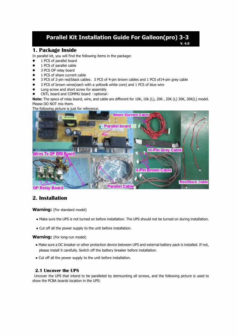
1. Package Inside In parallel kit, you will find the following items in the package:
1 PCS of parallel board
1 PCS of parallel cable
3 PCS OP relay board
1 PCS of share current cable
3 PCS of 2-pin red/black cables、3 PCS of 4-pin brown cables and 1 PCS of14-pin grey cable
3 PCS of brown wires(each with a yellow& white core) and 1 PCS of blue wire
Long screw and short screw for assembly
CNTL board and COMMU board(optional)
Note: The specs of relay board, wire, and cable are different for 10K, 10k (L), 20K , 20K (L) 30K, 30K(L) model.
Please DO NOT mix them.
The following picture is just for reference:
2. Installation
Warning: (For standard model)
● Make sure the UPS is not turned on before installation. The UPS should not be turned on during installation.
● Cut off all the power supply to the unit before installation.
Warning: (For long-run model)
● Make sure a DC breaker or other protection device between UPS and external battery pack is installed. If not,
please install it carefully. Switch off the battery breaker before installation.
● Cut off all the power supply to the unit before installation.
2.1 Uncover the UPS
Uncover the UPS that intend to be paralleled by demounting all screws, and the following picture is used to
show the PCBA boards location in the UPS:
Parallel Kit Installation Guide For Galleon(pro) 3-3 V. 4.0

2.2 Replace the CNTL board and COMMUNICATION board
Please ignore this step, if the the units you have bought were suitable for parallel function already.
For Gallon 3-3 UPS (10K,15K,20K,30K),there are 2 control boards, one for PFC control , and the other
for INV control, the following picture showing the different between these two boards, the part number (The
beginning 10 number of the series number) and firmware label (Label on the MCU) in the picture just for
reference, different version UPS may have different control board, the part number and firmware label may
different with the picture showing:
Make sure the UPSs that you want to parallel have the same part number, if different please sent the par number
to us for verifying.
In case you need to replace the control board, please following steps below:

Step 1: Replace PFC control board:
Remove the white glue.
Disconnect the 3-pin cable from CN7
of the PFC control board, demount
the small PCBA board.
Demount the 3 white screws,
disconnect the 50-pin cable.
Replace the PFC control board with a
new one. It is better assemble the
small PCBA first, then assemble the
new PFC control board by install the
3 screws, and then connect the
3-pin cables and 50-pin cables.

Step 2: Replace the INV control
board:
Remove the white glue, demount
the screw. Then pull the INV control
board.
Flipping over the INV control board,
you can see the glue on the
connectors, remove the glue, then
dis connect all the cables.
Replace the INV control board
with an new one, assemble the
new board back to the INV1&2
board.

Step 3: Replace the communication
board:
Take a new communication board,
demount the 2 screws of the DB-15
port.
Disconnect the cables on the
communication board, and demount
the srews that used to fasten the
communication board to the rear
panel.
Replace the board with a new one,
connect the cables, install the
screws.
2.3 Parallel kit installation
Step 1: Assemble the wires to
the OP relay board.
Step 2: Demount the 3 wires
from the O/P EMI board.

Step 3: Assemble the OP relay
boards to the location left of the
OP EMI board.
Step 4: Connect the OP relay
control and OP voltage detect
cables (4-pin brown cable):
Connect CN001 to CN15 of
INV1&2 board.
Connect CN002 to CN16 of
INV1&2 board.
Connect CN003 to CN15 of INV3
board.
Step 5: Connect the wires that
demounted from the OP EMI
board by “step2”:
Connect R1 to P1 of OP relay
board R
Connect S1 to P1 of OP relay
board S
Connect T1 to P1 of OP relay
board T
Step 6: Connect the wires that
with yellow & white core to the
OP EMI board:

Step 7: Take a new parallel
board, demount the 4 screws
from the parallel port ( DB15
Connectors)
Connect the “Parallel board power
supply cable” to CN9 of parallel
board.
Connect the “S phase current
equalizer cable” to CN10 of
parallel board.
Connect the “T phase current
equalizer cable” to CN11 of
parallel board.
Step 8: Remove covers for
parallel board port by demounting
2 screws.
Step 9: Assemble the parallel
board into the UPS:
Reference the left pictures please.
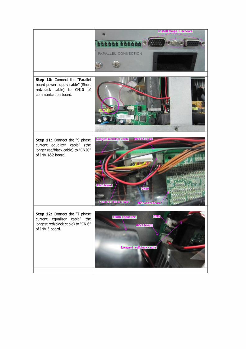
Step 10: Connect the “Parallel
board power supply cable” (Short
red/black cable) to CN10 of
communication board.
Step 11: Connect the “S phase
current equalizer cable” (the
longer red/black cable) to “CN20”
of INV 1&2 board.
Step 12: Connect the “T phase
current equalizer cable” the
longest red/black cable) to “CN 6”
of INV 3 board.

Step 13: Connect the 14-pin
grey cable to CN11 of INV control
board:
Please reference to Step2 of
part 2.2 to demount the INV
control board from the INV1&2
board.
Connect the 14-pin grey cable
to CN11 of INV control board.
Step 14: Assemble the INV
control board back to INV1&2
board, and then make the 14-PIN
grey cable through the middle
iron board.
Step 15: Connect the 14-pin
grey cable to CN1 of parallel
board.
At last, assemble all the cover back to the unit. Now the UPS is ready for parallel operation function.

Above is suitable for GALLON 3-3 10k, 15k, 20K,30K standard modle, for long backup modle, the difference is the
OP relay boards assembling, the following picture is for reference when assembling OP relay boards to the long
backup unit:
The Location Of OP Relay Board For Long Backup Unit
3. Wiring Connection for Parallel Operation
Please follow the below steps to connect cables and wires for Gallon 3-3 parallel models.
Step 1: Parallel cable and share current cable connection:
It is better to connect the “Share current cable” first, then connect the “parallel cable”. It’s all dummy-proof
design which can prevent customers from mis-connection. However, any stress to cables will cause bad
contact or broken inner wires. Please be aware of that.
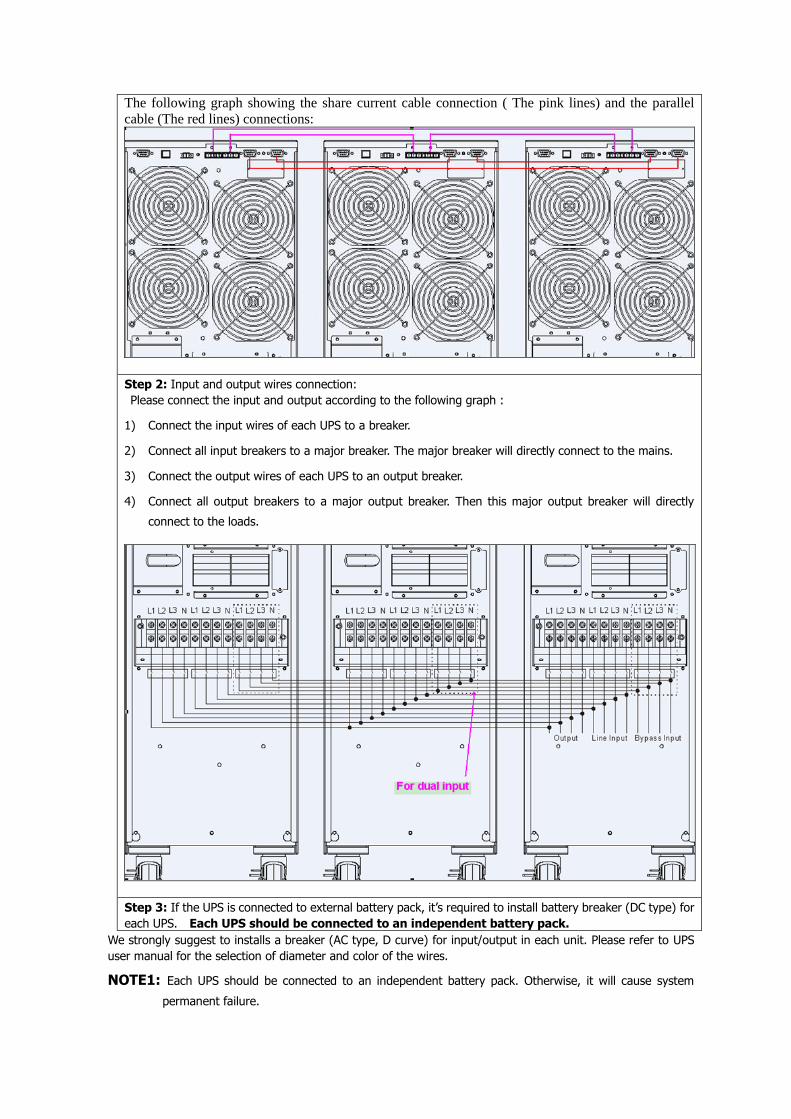
The following graph showing the share current cable connection ( The pink lines) and the parallel
cable (The red lines) connections:
Step 2: Input and output wires connection:
Please connect the input and output according to the following graph :
1) Connect the input wires of each UPS to a breaker.
2) Connect all input breakers to a major breaker. The major breaker will directly connect to the mains.
3) Connect the output wires of each UPS to an output breaker.
4) Connect all output breakers to a major output breaker. Then this major output breaker will directly
connect to the loads.
Step 3: If the UPS is connected to external battery pack, it’s required to install battery breaker (DC type) for
each UPS. Each UPS should be connected to an independent battery pack.
We strongly suggest to installs a breaker (AC type, D curve) for input/output in each unit. Please refer to UPS
user manual for the selection of diameter and color of the wires.
NOTE1: Each UPS should be connected to an independent battery pack. Otherwise, it will cause system
permanent failure.

NOTE2: For UPSs with isolation output transformers, the neutral of the input must be connected together after
the input distribution switch. You can connect the input N terminal of each UPS together directly.
4. Parallel Operation 1) Make sure that the parallel board and OP relay board have been installed correctly.
2) Make sure that each UPS has the same configuration, including the following parameters:
a) output voltage,
b) output frequency,
c) bypass voltage range,
d) bypass frequency range,
e) converter enable or disable,
f) bypass enable or disable,
g) bypass open or forbidden,
h) frequency auto detect enable or disable,
i) inverter short clear enable or disable
3) Turn on the UPS into the line mode or battery mode respectively, and measure the output voltage by
multimeter. Make sure the difference of the each phase output voltages among the UPSs is less than
1.5V(typical 1V). If not, you can adjust the inverter voltage of each UPS via LCD as bellow:
Inverter A voltage adjustment
Interface Setting
Parameter 2: you may choose Add or Sub to adjust inverter A voltage Parameter 3: the voltage range is from 0V to 9.9V, the default value is 0V.
Inverter B voltage adjustment
Interface Setting
Share current cable
Share current cable

Parameter 2: you may choose Add or Sub to adjust inverter B voltage* Parameter 3: the voltage range is from 0V to 9.9V, the default value is 0V.
*The number 1 under the or represent the inverter B
Inverter C voltage adjustment
Interface Setting
Parameter 2: you may choose Add or Sub to adjust inverter C voltage* Parameter 3: the voltage range is from 0V to 9.9V, the default value is 0V.
*The number 2 under the or represent the inverter C
After adjusting the inverter voltage, check whether the output voltage detecting is ok or not. Entering the
pictures as below via LCD, the LCD will display the output voltage detected. If the difference between the display
value and the voltage measured by mutimeter is more than 1V, adjusting it to make sure the difference is no
more than 1V. Then shut down the UPS to save this setting into EEPROM.
Output A voltage calibration
Interface Setting
Parameter 2: it always shows OP.V as output voltage. Parameter 3: it shows the internal measurement value of the output A voltage, and you can calibrate it by pressing Up or Down according to the measurement from an external voltage meter. The calibration result will be effective by pressing Enter. The calibration range is limited within +/-9V. This function is normally used for parallel operation.
Output B voltage calibration
Interface Setting
Parameter 2: it always shows OP.V as output voltage*. Parameter 3: it shows the internal measurement value of the output B voltage, and you can calibrate it by pressing Up or Down according to the measurement from an external voltage meter. The calibration result will be effective by pressing Enter. The calibration range is limited within +/-9V. This function is normally used for parallel operation.
*The number 1 under the represent the output S
Output C voltage calibration
Interface Setting

Parameter 2: it always shows OP.V as output voltage. Parameter 3: it shows the internal measurement value of the output C voltage, and you can calibrate it by pressing Up or Down according to the measurement from an external voltage meter. The calibration result will be effective by pressing Enter. The calibration range is limited within +/-9V. This function is normally used for parallel operation.
*The number 2 under the represent the output C
4) Connect the UPSs referring to the Section 3.
5) Turn on the parallel system with utility power supply (in AC mode)
a) Supply the parallel system with utility power.
b) Set each UPS’s breaker of the battery pack at “ON” position (ony for long-run model).
NOTE: the parallel UPSs can not use one battery pack. Each UPS should have its own battery pack.
Then set each UPS’s input breaker and output breaker at “ON” position. At this time the fan is running
and the UPS enter to power on mode for initialization, several seconds later, UPSs operates in Bypass mode.
After a while when UPSs’ output relays have closed, the parallel system supplies power to the loads via the
bypass.
c) Check the LCD whether displays the parallel information as showed in the below picture. If parallel
UPS systems are successfully set up, it will show “PAR” and assigned number as below picture. The
master UPS will be default assigned as “001” and slave UPSs will be assigned as either “002” or “003”.
If not see this picture, you can not go to next step and please check if the parallel cables have been
connected well.
d) Press and hold the “ON” button for 0.5s to turn on the UPS one by one, the buzzer will beep once and
the LCD will display the parallel process as showed in the below picture, the sign in the red circle will
twinkle until the UPSs entering to AC mode synchronously, the parallel system start to supply power to
the load.
6) Turn on the parallel system without utility power supply (in Battery mode)
a) Check if the parallel cables connected well please follow the below steps:
I) Turn on the battery breaker of each UPS (only for long-run model).
NOTE: 1.Do not turn on the output breaker of each UPS!
2.The parallel UPSs can not use one battery pack. Each UPS should have its own battery
pack!
II) Press the “ON” button of one UPS to set up the power supply, UPS will enter to power on mode.

After initialization UPS will enter to No Output mode, then Press and hold the “ON” button for 0.5s to turn
on the UPS, and the buzzer will beep once. A few seconds later, the UPS will be turned on and enter to
Battery mode.
III) Then do the same procedure to the other UPS according II), the LCD will display the parallel
process as showed in the below picture, the sign in the red circle will twinkle until the UPSs entering to the
battery mode:
IV) Check the LCD whether displays the parallel information as showed in the below picture. If parallel
UPS systems are successfully set up, it will show “PAR” and assigned number as below picture. The master
UPS will be default assigned as “001” and slave UPSs will be assigned as either “002” or “003”. If not see
this picture, you can not go to next step and please check if the parallel cables have been connected well.
V) Press “OFF” button for 0.5s of each UPS one by one to turn off all UPSs in parallel system.
b) Turn on the battery breaker (only for long-run model) and output breaker of each UPS.
c) Press the “ON” button of one UPS to set up the power supply, UPS will enter to power on mode. After
initialization UPS will enter to No Output mode, then Press and hold the “ON” button for 0.5s to turn
on the UPS, and the buzzer will beep once.
d) A few seconds later, the UPS will be turned on and enter to Battery mode.
e) Then do the same procedure to the other UPS according c), the LCD will display the parallel process as
showed in the below picture, the sign in the red circle will twinkle until the UPSs entering to the
battery mode:
f) Then the parallel system has been installed and starts to supply power to the load.
7) Turn off the parallel system
Press and hold the “OFF” button for 0.5s to turn off the UPS one by one, the buzzer will beep once.
After a while, the UPSs will enter to bypass mode or no output mode synchronously.
8) Add one new unit into the parallel system
a) You can not add one new unit into the parallel system when whole system is running. You must cut off
the load and shutdown the system.
b) Make sure all of the UPSs are the parallel models, and follow the connection refer to section 3.
c) Install the new parallel system refers to the previous section.
9) Remove one unit from the parallel system
There are two methods to remove one unit from the parallel system:
First method:
a) Press the “OFF” key twice and each time should be lasted for more than 0.5s, then the UPS will enter
into bypass mode or no output mode without output.
b) Turn off the output breaker of this unit, and then turn off the input breaker of this unit.
c) After it shutdown, you can move the parallel cable and share current cable. And then remove the unit
out of the parallel system.
Second method:
a) If the bypass is abnormal, you can not remove the UPS without interruption. You must cut off the load
and shut down the system first.
b) Make sure the bypass setting is enabled in each UPS and then turn off the running system. All UPS will
transfer to bypass mode.
c) Remove all the maintenance bypass covers and set the maintenance switches from “UPS” to “BPS”.
d) Turn off all the input breakers and battery breakers in parallel system.
e) Turn off the output breaker and move the parallel cable and share current cable of the UPS which you
want, then remove it out of the parallel system.
f) Turn on the input breaker of the remaining UPS and the system will transfer to Bypass mode. Set the
maintenance switches from “BPS” to “UPS and put the maintenance bypass covers back.
g) Turn on the remaining UPS according to 5).
Version Date Modification
1.0 20120810 New create
1.1 20140805 Some words correction
2.0 20140902 For UPS with isolation output transformer, need to join the neutral at
the input terminal of each UPS together. Because the input breaker of
the UPS never cut OFF the neutral.
3.0 20150324 Add 30K to the SOP and some small issue corrected.
4.0 20160130 Modify the control boards necessary for parallel description


![Galleon Comp[1]](https://static.fdocuments.in/doc/165x107/55cf922c550346f57b944a91/galleon-comp1.jpg)
