Parallel 3RRR Robot Classroom Guide - Vanderbilt...
27
Parallel 3RRR Robot Classroom Guide Advanced Robotics and Mechanism Applications Lab Vanderbilt University Garrison Johnston, Rashid Yasin, Long Wang, Nima Sarli, and Nabil Simaan July 7, 2016 1
Transcript of Parallel 3RRR Robot Classroom Guide - Vanderbilt...

Parallel 3RRR Robot Classroom GuideAdvanced Robotics and Mechanism Applications Lab
Vanderbilt University
Garrison Johnston, Rashid Yasin, Long Wang, Nima Sarli, and Nabil Simaan
July 7, 2016
1

Contents
1 Introduction 3
2 Getting The Course Files 4
3 The 3RRR Parallel Robot 4
4 Inverse Kinematics 5
5 Materials Needed 95.1 General Materials . . . . . . . . . . . . . . . . . . . . . . . . . . . . . . . . . . . . 95.2 Robot Parts . . . . . . . . . . . . . . . . . . . . . . . . . . . . . . . . . . . . . . . 95.3 Optional Materials . . . . . . . . . . . . . . . . . . . . . . . . . . . . . . . . . . . 11
6 Wiring 11
7 Robot Assembly 12
8 Software 178.1 Software Set Up . . . . . . . . . . . . . . . . . . . . . . . . . . . . . . . . . . . . . 178.2 Uploading to The Arduino . . . . . . . . . . . . . . . . . . . . . . . . . . . . . . . 17
9 Servo Motors 18
10 The Arduino Code Repository 20
11 Calibration 2011.1 Introduction to Calibration . . . . . . . . . . . . . . . . . . . . . . . . . . . . . . 2011.2 Calibration Step One . . . . . . . . . . . . . . . . . . . . . . . . . . . . . . . . . . 2111.3 Calibration Step Two . . . . . . . . . . . . . . . . . . . . . . . . . . . . . . . . . . 2211.4 Calibration Summary . . . . . . . . . . . . . . . . . . . . . . . . . . . . . . . . . . 22
12 Telemanipulation 24
A How to Use a Breadboard 26
B Polar vs. Non-Polar Capacitors 26
C The atan2 Function 26
2

1 Introduction
According to the Robot Institute of America, a robot is a ”reprogrammable, multifunctionalmanipulator designed to move material, parts, tools, or specialized devices through various pro-grammed motions for the performance of a variety of tasks.” The use of the word robot firstarose from the 1921 stageplay R.U.R. (Rossum’s Universal Robots) written by Czech playwrightKarel Capek [19]. Now, less than 100 years later, robots are an integral part of the moderneconomy. They are used in industrial factories, in the military, in space and ocean exploration,in medicine, and in consumer products to name only a few applications. Into the future, robotswill continue to become a larger and larger part of the human experience, making human livessafer and easier.
Robot manipulators are typically subdivided into two main categories: serial and parallel.In a serial robot, the position of the end effector, the part of the robot that interacts with theenvironment, is determined by a series of links making an anthropomorphic (arm-like) structure[17]. Figure 1 shows a few examples of serial manipulators.
Anthropomorphic Manipulator SCARA Manipulator Gantry Manipulator
Figure 1: Serial robot examples (anthropomorphic [23], SCARA [14], gantry [22])
In parallel robots, the position of the end effector is determined by multiple arms workingat the same time (in parallel) [17]. Figure 2 shows a few examples of parallel manipulators.
3

3RRR Manipulator Delta Manipulator Stewart/Gough Platform Manipulator
Figure 2: Parallel robot examples (3RRR [11], delta [15], stewart/gough [16])
This classroom activity uses a 3RRR parallel robot similar to that shown in Figure 2, whichis explained in detail in Section 3.
2 Getting The Course Files
Before you begin, you should first download the course materials. The following URL linksto a Dropbox folder called ARMA NRI 3RRR Robot : https://goo.gl/ktm3Lp. This foldercontains all the files needed for this course. The course files can also be found on the main courseweb-page.
3 The 3RRR Parallel Robot
The name 3RRR comes from the robot’s construction. The position and orientation of the robotis controlled by three kinematic chains (the name for an assembly of mechanical linkages) hencethe 3 in the name. The RRR comes from the three revolute joints in each kinematic chain. Arevolute joint is a mechanical linkage that only allows rotation about one axis.
4

Kinematic Chain
Revolute Joint
Input Link
Motor
Figure 3: Kinematic chains and revolute joints (adapted from [11])
This mechanical arrangement allows controlling the position and the orientation of the mov-ing platform in a plane parallel to the base platform. By controlling the angles of the three inputlinks the moving platform can be controlled.
This classroom activity uses a 3RRR robot to demonstrate basic use of trigonometry andmath to program and control the robot using an Arduino microcontroller.
4 Inverse Kinematics
In order for a robot to perform a task, it must be able to accurately move to a specified locationin space. This may seem obvious, but it is a central problem in robotics. To solve this, engineersuse the geometry of the robot to determine a mathematical expression that relates the positionof the end effector to the joint angles. In other words, to what angle should the motors be set inorder to make the robot move to a pre-determined location. This is called kinematic analysis [19].There are two types of kinematic analysis: forward and inverse. Forward kinematics determinesthe position of the end effector as a function of its joint angles. Inverse kinematics determinesthe joint angles as a function of the end effector position [17]. This section will briefly explainthe inverse kinematics of the 3RRR robot.
Figure 4 shows the names of the joint angles and points used in the mathematical formulationof the robot’s inverse kinematics. The point P is the center of the robot which is at the orientationθ and q1,q2, and q3 are the corresponding joint angles. To formulate the inverse kinematics youneed to find q1, q2, and q3 as a function of P and θ. Along the way you will use the other pointsin Figure 4 and define some new ones. The first step is to make a circle around the center of themoving platform of the robot as shown in Figure 5.
5

𝒃3
𝒃2
𝒃1
𝒆1
𝒆2
𝒆3
𝒂1
𝒂2
𝒂3
𝑞1
𝑞2
𝑞3
𝒑
𝜃y
x
Figure 4: Schematic of the parallel robot for inverse kinematics
Figure 5: Inverse kinematics step one
Using this, you can derive the x and y positions of points a1,a2, and a3.
a1x = px + rp cos(θ − π
6
)(1)
a1y = py + rp sin(θ − π
6
)(2)
a2x = px + rp cos(θ +
π
2
)(3)
a2y = py + rp sin(θ +
π
2
)(4)
6

a3x = px + rp cos(θ +
7π
6
)(5)
a3y = py + rp sin(θ +
7π
6
)(6)
Now that these positions are known, the next step is to determine the position of motorshafts, points b1,b2, and b3, using a similar method to equations 1 to 6. A circle circumscribingthe equilateral triangle b1,b2, and b3 is drawn as shown in Figure 6.
𝒃3
𝒃2
𝒃1
𝒆1
𝒆2
𝒆3
𝒂1
𝒂2
𝒂3
𝑞1
𝑞2
𝑞3
𝒑
𝑟𝑏
Figure 6: Inverse Kinematics step two
b1x = rb cos(−π
6
)= rb
√3
2(7)
b1y = rb sin(−π
6
)= −rb
2(8)
b2x = rb cos(π
2
)= 0 (9)
b2y = rb sin(π
2
)= rb (10)
b3x = rb cos(
7π
6
)= rb
√3
2(11)
b3y = rb sin(
7π
6
)= −rb
2(12)
7

Because the center of the motors are fixed, these equations can be simplified further thanequations 1 to 6. In order to solve for the values of q1,q2, and q3, two alternate motor angles, ψand α, must be introduced as shown in Figure 7.
𝒃3
𝒃2
𝒃1
𝒆1
𝒆2
𝒆3
𝒂1
𝒂2
𝒂3
𝑞1
𝑞2
𝑞3
𝒑
𝜃
𝜓2
𝜓1𝜓3𝛼1
𝛼2
𝛼3
y
x
Figure 7: Inverse kinematics step three
You can now find equations for ψ1, ψ2, and ψ3. These equations use the atan2 function. SeeAppendix C for an explanation of the atan2 function.
ψ1 = atan2(a1y − b1y, a1x − b1x) (13)
ψ2 = atan2(a2y − b2y, a2x − b2x) (14)
ψ3 = atan2(a3y − b3y, a3x − b3x) (15)
Using the law of cosines and the distance formula, you can find α1, α2, and α3.
α1 = arccos
((b1e1)
2 + ((b1x − a1x)2 + (b1y − a1y)2)− (a1e1)2
2 ((b1x − a1x)2 + (b1y − a1y)2) (b1e1)
)(16)
α2 = arccos
((b2e2)
2 + ((b2x − a2x)2 + (b2y − a2y)2)− (a2e2)2
2 ((b2x − a2x)2 + (b2y − a2y)2) (b2e2)
)(17)
α3 = arccos
((b3e3)
2 + ((b3x − a3x)2 + (b3y − a3y)2)− (a3e3)2
2 ((b3x − a3x)2 + (b3y − a3y)2) (b3e3)
)(18)
Finally, the last step is to solve for q1,q2, and q3.
8

q1 = ψ1 − α1 (19)
q2 = ψ2 − α2 −2π
3(20)
q3 = ψ3 − α3 −4π
3(21)
These equations have been simplified, but they represent the inverse kinematic model of the3RRR robot. Algorithm 1 summarizes the process of solving the inverse kinematics of the 3RRRrobot.
Algorithm 1 Inverse kinematics summaryInputs:θ, P (x, y)Process:calculate: a1, a2, a, 3, (Eq. 1-6)calculate: b1, b2, b3, (Eq. 7-12)calculate: ψ1, ψ2, ψ3, (Eq. 13-15)calculate: α1, α2, α3 (Eq. 16-18)
calculate: qi = ψi − αi − (i− 1)2(i−1)π3
The file 3RRR Kinematic Simulator.jar is an applet that simulates the kinematics of the3RRR robot [13]. Take some time playing with this applet to get an understanding of how therobot moves.
5 Materials Needed
In order to complete this project, you are going to need to purchase materials. Unfortunately,these materials cannot be purchased all from the same location. This section will outline all thematerials needed and how to purchase them.
5.1 General Materials
To set up the robot, you will need the items in Table 1The following link will take you to a Digi-Key shopping cart that has all the correct parts:
http://www.digikey.com/short/34258p. You can buy all of the parts there if you wish orsimply use it as a reference. A PDF version of the shopping cart is included in the course filesin the folder Orders. If you purchase the materials elsewhere be careful to purchase the correctitems or the project may not function correctly.
5.2 Robot Parts
The parts for the robot itself can be purchased from a 3D printing service called Shapeways.This link takes you to a Shapeways shop where you can order the parts to be printed: https:
//www.shapeways.com/shops/arma-lab-3rrr-robot. Once you follow this link, purchase both
9

Table 1: Bill of materialsNo. Desciption Quantity
1 Arduino Uno 12 USB-A to USB-B Cable 13 L7805CV Voltage Regulator 14 0.1 µF Capacitor 15 0.33 µF Capacitor 16 Breadboard 17 Assorted Jumper Wires >208 10kΩ Potentiometer 19 Tower Pro SG92R Micro Servo Motor 310 9V Power Source 111 7/16” #4-40 Screws 612 #4-40 Hex Nuts 613 1/2” #6-32 Shoulder Screws 914 #6-32 Hex Nuts 615 8mm M2 Screws 816 M2 Hex Nuts 8
items. Don’t worry, the ARMA Lab is not making any profit off of these parts. If you have accessto a 3D printer and wish to print the parts yourself, the .stl files can be found in the course folderunder Robot Parts. These are all the parts needed to complete this project.
Base
Motor Arm x3
Middle Arm x3Platform
Pencil Adapter
Figure 8: Robot parts
Figure 8 shows the parts needed for the robot and the names they will be referred to in thisdocument.
10

5.3 Optional Materials
If you or your instructor have soldering capabilities, you can also purchase the parts for a joystickfrom this link: http://sfe.io/w129046. A PDF version is also available in the Orders folder.More about this is talked about in Section 12.
6 Wiring
Now that you have all the materials needed, it is time to start wiring the robot.
Power Supply
USB to Computer
To Pin 5
To Pin 6
To Pin 9To Pin A0
Breadboard0.33μFCapacitor
0.1μF Capacitor
- + -+
Figure 9: Wiring diagram
Figure 10: Wiring diagram detail view
Complete all the connections as shown in Figures 9 and 10. If you do not know how to usea breadboard please refer to Appendix A
If you used capacitors other than those recommended in the Digi-Key shopping cart, itis important to note that some capacitor types are polar. This means they have a positiveand negative terminal and therefore must be oriented in the correct manner. If you used therecommended capacitors, you do not need to worry about this, but if you did not buy therecommended capacitors please refer to Appendix B.
11

Figure 9 shows the 9V supply as a battery, but it is better to use a power supply similarto the one recommended in items 10 and 11 in the Digi-Key shopping cart (this is a wall wartand an alligator clip adapter) because a battery would be quickly drained due to the large powerdraw of the circuit. However, if you cannot get access to a power supply, a 9V battery will alsowork.
This circuit has several components that work together to control the robot’s servos. TheArduino is a microcontroller that interprets the code from the Arduino IDE and outputs anelectrical signal with the correct pulse width specified in the code [3]. A potentiometer is adevice that changes its impedance when the knob is turned [1]. The potentiometer in this circuitwill allow you to control the position of the servos manually. The servos used in the robot operateat 5V so the voltage regulator is used to keep the voltage going to the servos at this value. Thecapacitors are used to increase the output stability of the regulator [21].
7 Robot Assembly
The first step to assembling your robot is attaching the servos to the base plate. The process forassembling one servo is is shown in Figure 11.
8mm M2 Screws
M2 Nuts
SG92R Servo
Figure 11: Servo Assembly
The next step is to attach the servo adapter that comes with the servo to the robot’s motorleg. To do this, you must widen the holes shown in Figure 12 using a 1
8” drill bit.
12

Figure 12: Holes to Widen on Motor Adapter
Next, assemble the servo adapter to the motor leg as shown in Figure 13.
#4-40 NutsMotor Arm
Servo Adapter
#4-40 Screws
Figure 13: Assembling the Servo Adapter to the Motor Leg
After you have done this, attach the assembly from Figure 13 to the servo. To do this youwill need the long screw that comes with the servo. Figure 14 shows how to do this.
13

Screw From Servo Package
Figure 14: Assembling the motor leg to the servo
Once you have assembled this part, make sure that the motor arm can move from the 5 lineto the 175 line. If it cannot, change the orientation of the assembly in 14 until it can move toboth lines.
The next step is to attach the middle arm to the motor arm. Figure 15 shows this process.
Shoulder Screw
#6-32 Nut
Middle Arm
Figure 15: Assembling the middle arm
The next step is to assemble the pencil adapter to the platform as shown in figure 16. Thepencil adapter allows a pencil to be added to the center of the platform to trace the location ofthe robot on a piece of paper.
14

M2 Screws
Pencil Adapter
M2 Hex Nuts
Figure 16: Assembling the pencil adapter
Finally, the platform is attached as shown in Figure 17. The other arms and pencil adapterwere removed from this figure for clarity.
Shoulder Screw
#6-32 Screw
Platform
Figure 17: Assembling the platform
It is important note that there is a correct and incorrect method of assembling the centerplatform. The incorrect assembly is shown in Figure 18 and the correct assembly is shown infigure 19. These robots will look slightly different than yours, but the concepts are the same.The coordinate axis on the center platform was added as a visual aid.
15

Figure 18: Incorrect assembly of center platform
Figure 19: Correct assembly of center platfrom
16

If the center platform is assembled incorrectly, the robot will not be able to reach all thepoints in its workspace because it will hit singularities or configurations where the robot losesone or more degrees of freedom (ability to move in a given direction).
8 Software
8.1 Software Set Up
In order to set up the Arduino software, follow this link https://www.arduino.cc/en/Main/
Software, download the Arduino software, and run the installation instructions. This will installthe Arduino Integrated Development Environment (IDE). Programs in the Arduino IDE arewritten in a programming language called Arduino which is C/C++ with a slightly differentorganizational structure [3]. Once you have installed the Arduino IDE, open the Arduino codefolder from the course folder you downloaded earlier. In this folder will be a subfolder calledcalibration. Copy this folder to the \documents\Arduino\libraries directory that was created onyour computer during the Arduino installation. In the calibration folder there is a file calledcalibration.h. Right click on this file, go to open with, and select Notepad (or any other texteditor). Notepad should open showing the code for a C++ library. A library is a repositoryof useful classes, variables, etc. that can be included in other C++ code to increase ease ofdevelopment [2]. You will be editing some of the variables in this library as you calibrate therobot. Leave this file open on your computer. This is all the software set up needed.
8.2 Uploading to The Arduino
In order to run a program on an Arduino, you must upload the program to the board (theArduino IDE calls a program a sketch). To do this you must open the file you wish to run inthe Arduino code folder you downloaded earlier. This will open the Arduino IDE. In the IDE,press the blue button at the top of the window as indicated in Figure 20. This will upload theprogram to the Arduino.
Once the program is done uploading to the Arduino, the bottom of the IDE window shouldlook similar to Figure 21.
Figure 21: Arduino ”done uploading” message
If everything is wired correctly, the robot should be working. If the robot doesn’t work,consider these common mistakes:
• Is the 9V power source turned on?
17

Figure 20: Arduino IDE upload button
• Have any connections been incidentally placed in the wrong row/column?
• Are all the connections making solid contact?
• Did you overlook one of the connections in Figures 9 and 10?
• Are the capacitors and voltage regulator oriented correctly?
9 Servo Motors
Figure 22: Servo motor [6]
Before you can calibrate your robot, it is important to understand servo motors and how theyare controlled. Servos are a type of motor commonly used in robotics that allow engineers tospecifically control the angular position of the shaft. They consist of four different parts: a DC
18

Figure 23: Servo components [18]
motor, a control circuit, a potentiometer, and usually a set of gears as shown below in Figure 23[19].
The DC motor is used to move the mechanism, the control circuit is used to interpret theinput signal and feedback loop, the potentiometer is used as a position sensor, and the gearsprovide a speed/torque transformation to the motion of the DC motor. If you examine theservos you will notice that there are three wires feeding into the motor. The brown wire isground, the red wire is power, and the yellow wire is the signal used to control the servo. Thissignal uses pulse width modulation (PWM) to control the position of the motor [19].
On
Off
Figure 24: Pulse width modulation [7]
Pulse width modulation is a method of creating analog signals out of digital (0 or 1) signals.For this robot, an Arduino board is used to send a signal to the servo that pulses on and off. Bychanging the amount of time the signal is ”on,” shown as the ”pulse width” in Figure 24, themotor can be moved to different locations. To calibrate the robot’s servos you will determinethe pulse widths, in microseconds (µs), that correspond to various angular positions. This willallow you to interpolate the µs value of any desired servo position. As a side note, the typeof PWM that servos use differs slightly from the traditional use of the term. Usually, PWM istalked about in terms of the signal’s ”duty cycle” or percentage of the signal’s period that it is”on,” but servos simply count the amount of time the signal is ”on” [4].
19
10 The Arduino Code Repository
In the Dropbox folder you downloaded earlier, there is a folder called Ardiuno Code. In thisfolder, you will find several Arduino sketches that command the robot to do various things.Table 2
Table 2: Arduino code descriptionsFile Name PurposeRRR Circle Path Commands robot to move in a circle around the originRRR epicycloid path Commands robot to move in a epicycloid path about the
originRRR mirosecond calibrate pot Uses potentiometer to assist in setting the microsecond
delays corresponding to 5 and 175
RRR parallel robot go to home Commands the robot to go to the originRRR parallel robot roll origin Commands the robot to alternate its orientation back and
forth from 30to -30while staying fixed about the originRRR roll about origin pot control Commands the robot to move in a similar fashion to
RRR parallel robot roll origin except controlled by thepotentiometer
RRR Telemanipulation Allows for the robot to be controlled using a joystick. Seesection 12 for more details.
After you have calibrated the robot, you can run these sketches and watch the robot move.If you want the robot to draw out its path, place a blank sheet of paper under the robot on thebase and place a pen in the center hole of the platform.
11 Calibration
11.1 Introduction to Calibration
Once the kinematics of the robot is known, it is necessary to command the servos to the desiredangular position. However, motors only understand electrical signals so engineers must figureout the relationship between the input signal and the angular position of the motor [19]. Also,it is impossible to manufacture a robot perfectly so there will always be some error created bythe robot’s construction [1]. Engineers must compensate for this error. These two things arecollectively referred to as calibration.
This course’s robot is calibrated by determining the pulse width that corresponds to a 5
rotation and a 175. Using these values, any position of the servos can be interpolated. Equation22 shows the equation used to determine the pulse width that corresponds to a desired angularposition.
m =mmax −mmin
θmax − θmin(θdesired − θmin) +mmin (22)
In Equation 22, m is the pulse width (in microseconds) that correspond to the desired angularposition (θdesired). mmax and mmin are the pulse widths that correspond to a 175 (θmax) and 5
(θmin) position of the servos respectively.
20

This section will walk you through how to calibrate the course’s parallel robot. There isalso an online video explaining the calibration process that can be found here: https://goo.
gl/gLn7wS. It can also be found on the course web-page.
11.2 Calibration Step One
Once you have ensured that the robot is working, remove the center and middle legs of the robotas indicated in Figure 25. For reasons that will become apparent later, this will make calibrationmuch easier.
Figure 25: Removing the middle section
The first step to calibrate the robot is to find the microsecond pulse delay that correspondsto a 5 position of Servo 1. To do this, uploadRRR_microsecond_calibrate_pot.ino to the Arduino. You will next need to open the Ar-duino’s serial monitor. To do this click on the serial monitor button as shown in Figure 26.
Figure 26: Button to open the serial monitor
This will open a window that displays the current pulse width in microseconds and the anglethe servo thinks it is at in degrees. Next, open the calibration.h file as described earlier. Inthis file, you will find a line that reads double m of theta min[3]=580,713,752;. Thisline tells the computer to initialize an array (a grouping of adjacent items in memory undera common name) of three double (a number rounded to 15 decimal places) data types calledm of theta min and assign it the values of 580, 713, and 752. The semicolon tells the computerthe line of code is over [2]. This variable is the pulse width that the Arduino sends to Servo 1
21

to command it to 5. Turn the potentiometer until you see servo 1 line up exactly with the 5
notch as shown in Figure 27. Change the first value in m of theta min to equal the value ofthe pulse width on the serial monitor. If the arm does not reach the 5 notch, decrease the firstvalue of m of theta min until you can reach the 5 notch. Save calibration.h and re-uploadRRR_microsecond_calibrate_pot.ino.
Figure 27: 5 alignment
Next, turn the potentiometer until Servo 1 lines up with the 175 notch. Then change thefirst value of m of theta max to equal the pulse width value on the serial monitor.
Once this is completed, change the value of the variable i in the Ardino IDE to be 1. Thiswill change the code so that Servo 2 moves when the potentiometer is turned. repeat the aboveprocess changing the second values of m of theta min and m of theta max making sure tosave calibration.h each time you change a value. Again, repeat for Servo 3 by changing i to 2and editing the third values of m of theta min and m of theta max.
You have now completed the first step to calibrating your robot. If this has been donecorrectly, you should be able to turn the potentiometer and make each servo move from their 5
lines to their 175 lines. You are now ready to move on to step two.
11.3 Calibration Step Two
Because of the way the robot is assembled, there will be positional errors in the robot’s endeffector position. In this section you will attempt to negate this. Change i back to zero and turnthe potentiometer until servo 1 lines up with the 90 notch. Check the serial monitor to whatangle the robot thinks it is at, replace the first value of the array q home offset in calibration.hto be 90− θ where θ is the position servo 1 thinks it is at.
Reassemble the robot, then open the file RRR_parallel_robot_go_to_home.ino and uploadit to the Arduino. This will command the robot to the center of the board. if the robot iscalibrated correctly the center of the moving platform will exactly line up with the center of thebase.
11.4 Calibration Summary
Algorithm 2 summarizes the calibration process for the 3RRR robot detailed in Sections 11.1 to11.3.
22

Algorithm 2 Calibration Summary1: Open calibration.h (Sec. 8.1)2: Open and upload RRR_microsecond_calibrate_pot.ino to the Arduino (Sec. 8.2)3: Open serial monitor (Fig. 26)4: Turn potentiometer until Servo arm lines up with 5 notch (Fig. 27)5: Edit first term in array m of theta min to equal the pulse width displayed on the serial monitor
(Sec. 11.2)6: Turn potentiometer until Servo arm lines up with 175 notch (Sec. 27)7: Edit first term in array m of theta max to equal the pulse width displayed on the serial monitor
(Sec. 11.2)8: Change value of i to 1 to change to Servo 2 (in C indexing starts at zero)(Sec. 11.2)9: Save calibration.h (Sec. 8.1)
10: Repeat steps 2-7, this time editing the second values in m of theta max and m of theta min(Sec. 11.2)
11: Change value of i to equal 2 to change to Servo 3 (in C indexing starts at zero)(Sec. 11.2)12: Save calibration.h (Sec. 8.1)13: Repeat steps 2-7 this time editing the third values in m of theta max and m of theta min (Sec.
11.2)14: Change i back to zero15: Upload RRR_microsecond_calibrate_pot.ino to the Arduino (Sec. 8.2)16: Turn the potentiometer until servo 1 lines up with the 90 notch (Sec. 11.3, Fig. 27)17: Check the serial monitor to what angle the robot thinks it is at, replace the first value of the array
q home offset in calibration.h to be 90 − θ where θ is the position servo 1 thinks it is at. (Sec.11.3)
18: Save calibration.h (Sec. 8.1)19: Change i to 1 to change to servo 220: Repeat steps 15-18 this time changing the second value of q home offset (Sec. 11.3)21: Save calibration.h (Sec. 8.1)22: Change i to 2 to change to servo 323: Repeat steps 15-18 this time changing the third value of q home offset (Sec. 11.3)
23

12 Telemanipulation
Note: this section requires soldering so if you and/or your instructor do not have soldering ca-pabilities, you will unfortunately not be able to complete this section. A soldering tutorial can befound here: https://learn.sparkfun.com/tutorials/how-to-solder---through-hole-soldering.
This section will show you how to move your robot by using a joystick. This is calledtelemanipulation. First you will need to purchase the items in this SparkFun wishlist: http:
//sfe.io/w129046. A PDF version of this order can be found in the course files Orders folder.First you will need to solder the joystick to the breakout board and then solder five jumper
cables to the holes labeled VCC, VERT, HORZ, SEL and GND. After this is completed, wirethe Arduino using the schematic in Figure 28.
Figure 28: Telemanipulation wiring diagram
When you have finished wiring this, you will now be able to change the robot’s position bymoving the joystick.
References
[1] David G Alciatore. Introduction to Mechatronics and Measurement Systems. Tata McGraw-Hill Education, 2007.
[2] Alex Allain. Jumping into c++. CIT, 105, 2014.
[3] Arduino.cc. Introduction to Arduino, 2016.
[4] Micheal Barr. Introduction to Pulse Width Modulation (PWM). Barr Group, 9 2001.
24

[5] Hernando Barragan. What is a Breadboard? Wiring.
[6] Conrad. Modelcraft Mini servo Analogue servo Gear box material Plastic Connector systemJR.
[7] Embedded Micro. Pulse-Width Modulation, 2015.
[8] Every China. CL11(PEI) MYLAR CAPACITOR, 2016.
[9] Future Electronics. .001uF 50V Ceramic Capacitors.
[10] Guangdong Fenghua Advanced Technology Holding Co. Ltd. Leaded Tantalum ElectrolyticCapacitor with Large Capacitance and 4 to 50V Voltage Rating, 2016.
[11] Human and Robot Interaction Laboratory. Parallel Mechanisms: Design, Development andControl of 3-RRR Planar Parallel Mechanism, 2014.
[12] MathWorks. atan2, 2016.
[13] Miguel Hernndez University: Automation, Robotics and Computer Vision lab. Parallel3RRR Robot.
[14] Omron Adept Technologies, INC. SCARA Robot - Adept Cobra s350 SCARA 4-Axis Robot,2016.
[15] Penta Robotics. Veloce.
[16] Physik Instrumente. H-840 6-Axis Hexapod, 2016.
[17] Jon M Selig. Introductory Robotics, volume 5. Prentice Hall Englewood Cliffs, NJ, 1992.
[18] Servo City. How Do Servos Work?, 2015.
[19] Bruno Siciliano, Lorenzo Sciavicco, Luigi Villani, and Giuseppe Oriolo. Robotics: Modelling,Planning and Control. Springer Science & Business Media, 2010.
[20] Simple Electronics. Capacitor Types, 7 2013.
[21] ST Microelectronics. Positive voltage regulator ICs, 2 2016. Rev. 33.
[22] Jorg Tertunte and Lisa Endrijaitis. Switching from Robot Systems to Cartesian HandlingSystems. Linear Motion Tips, 11 2014.
[23] TU: Berlin - Robotics and Biology Laboratory. Robotics: Facilities, 4 2016.
25

Figure 29: Breadboard connections [5]
A How to Use a Breadboard
Breadboards, which are also sometimes called protoboards, are used to easily prototype circuitry.They are a plastic board with a matrix of holes that are internally connected to expedite wiring.In Figure 29 all columns are internally connected in the manner shown by the blue column B.Any wire put into any of the holes will be connected to all the other holes in the column. Onthe top and bottom of the breadboard the rows are internally connected as indicated by the pinkline A. These rows are called the ”power rails” because they are traditionally where the powerand ground are connected. It is important to note that the breaks in the power rail rows areinternally connected while the breaks in the columns are not connected as indicated in Figure29. This is to allow a DIP to be inserted into the breadboard.
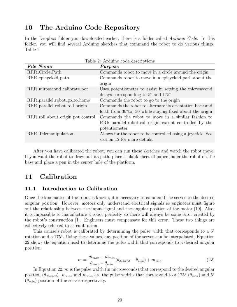
B Polar vs. Non-Polar Capacitors
The positive and negative signs on the capacitors in Figure 9 indicate which orientation thecapacitors should be in if they are polar. Figure 30 shows some common polar and non-polarcapacitor types. Needless to say, this list is not exhaustive and you should research the type ofcapacitor you have to determine if it is polar. In general, if one of the capacitor’s leads (the wiresleading to the capacitor) is longer than the other, it is polar and the longer lead is the positiveterminal [1].
C The atan2 Function
The atan2 function is a variant of the inverse tangent (arctan) function. It is used because tanis multivalued. This means that it has multiple valid solutions existing in different quadrants.For example, tan
(3π4
)= tan
(−π
4
)= −1 despite the fact that 3π
4is in quadrant 2 and −π
4is in
quadrant 4. This makes the solution to arctan(−1) ambiguous. The atan2 function solves thisissue by taking the x and y coordinates as two separate arguments, atan2(y, x). Using the inverse
26
Polar Capacitors
Non-Polar Capacitors
Electrolytic Tantalum
Film Ceramic
+-
+-
Figure 30: Common capacitor types: polar vs. non-polar (electrolytic [20], tantalum [10], film[8], ceramic [9]
of the example above, while arctan(−1) could equal either 3π4
or −π4, atan2 has unambiguous
solutions to both cases. atan2(−1, 1) = −π4
and atan2(1,−1) = −3π4
[12].
27


![Advanced Synthesis of the DELTA Parallel Robot for a ... · The DELTA robot (see figure 1) is one of the most famous translational parallel manipulators [5,6,7]. However, as most](https://static.fdocuments.in/doc/165x107/60deb7bb75750716bc06342b/advanced-synthesis-of-the-delta-parallel-robot-for-a-the-delta-robot-see-figure.jpg)