Paragon Caldera Instruction & Service Manual · Paragon Caldera Instruction & Service Manual. ......
20
Paragon Caldera Instruction & Service Manual
Transcript of Paragon Caldera Instruction & Service Manual · Paragon Caldera Instruction & Service Manual. ......

ParagonCaldera
Instruction& ServiceManual

IntroductionThank you for choosing a Paragon Caldera kiln! We havedesigned it to give you many years of reliable service.
Please read this manual. It will help you gain the mostenjoyment from your Caldera kiln. It will show you how toavoid damaging the kiln and will answer many questions. Ifyour kiln is digital, your instruction packet will include aseparate digital controller manual. Please save bothmanuals.
Inspect the kiln. When you receive your kiln, check thecarton for damage (crushed, holes, etc.). Check the kiln forboth interior and exterior damage. If the kiln is damaged,you can refuse the shipment and have it returned, or acceptthe shipment after having the driver note the damage on theBill of Lading. Then call Paragon at 800-876-4328 or972-288-7557 (open Monday to Thursday, 7 a.m. to 5:30p.m. Central).
Check the Bill of Lading to insure that you received thecorrect number of packages. Note any shortages on the Billof Lading, and have the driver sign the copy.
If there were no signs of visible kiln damage and you dis-cover it after the driver has left, notify the shipperimmediately.
Needless worries. Tremendous stresses are generatedwithin the kiln. The insulating firebricks actually expandand contract with each firing. Do not be concerned if smallcracks appear in the bricks. This is normal. These are sur-face cracks that close tightly when the heated brickexpands.
During firing, you will hear an intermittent, distinct click-ing. In a digital kiln, this is the sound of the relay sendingpower to the heating elements. In a manual kiln, it is the in-finite control switch cycling on and off. Do not be con-cerned with this sound.
The Electrical data plate.Important information aboutyour kiln is recorded on itselectrical data plate. Please in-clude this information whenordering parts or calling yourdealer or the factory about your kiln.
2/
ContentsSetting Up the Kiln . . . . . . . . . . . . . 4
Electrical Installation . . . . . . . . . . . . . . . . . . . . . . 4Seating the Elements. . . . . . . . . . . . . . . . . . . . . . 4Where to Locate the Kiln . . . . . . . . . . . . . . . . . . . 4
Basic Operation . . . . . . . . . . . . . . . 5Accessories . . . . . . . . . . . . . . . . . . . . . . . . . . . . . 5Important Guidelines . . . . . . . . . . . . . . . . . . . . . . 5Loading the Kiln. . . . . . . . . . . . . . . . . . . . . . . . . . 6Venting the Kiln . . . . . . . . . . . . . . . . . . . . . . . . . . 7
Glass Fusing & Slumping . . . . . . . 7How to Cut Glass. . . . . . . . . . . . . . . . . . . . . . . . . 7Fusing Compatibility of Glass . . . . . . . . . . . . . . . 8The Annealing Range . . . . . . . . . . . . . . . . . . . . . 8Cleaning and Gluing the Glass . . . . . . . . . . . . . . 8Load Glass Into the Kiln . . . . . . . . . . . . . . . . . . . 8Firing the Glass . . . . . . . . . . . . . . . . . . . . . . . . . . 8Annealing Flame-Worked Glass Beads . . . . . . . 9
Enameling on Metal . . . . . . . . . . . 10How to Load the Kiln . . . . . . . . . . . . . . . . . . . . . 10Preparation of the Copper. . . . . . . . . . . . . . . . . 10Decorating the Copper . . . . . . . . . . . . . . . . . . . 10Firing Enamel. . . . . . . . . . . . . . . . . . . . . . . . . . . 11
Ceramics . . . . . . . . . . . . . . . . . . . . 11Pyrometric Cones . . . . . . . . . . . . . . . . . . . . . . . 11Viewing the Cones During Firing. . . . . . . . . . . . 11Orton Cone Chart . . . . . . . . . . . . . . . . . . . . . . . 12Firing Overglaze . . . . . . . . . . . . . . . . . . . . . . . . 12Firing Low Fire Greenware . . . . . . . . . . . . . . . . 12Firing Low Fire Glaze. . . . . . . . . . . . . . . . . . . . . 13Firing Porcelain Greenware. . . . . . . . . . . . . . . . 13Firing Porcelain Glaze . . . . . . . . . . . . . . . . . . . . 13Firing Stoneware Greenware or Glaze . . . . . . . 13Glaze Testing. . . . . . . . . . . . . . . . . . . . . . . . . . . 13
Silver & Gold Clay . . . . . . . . . . . . . 14Drying Time . . . . . . . . . . . . . . . . . . . . . . . . . . . . 14Loading the Kiln. . . . . . . . . . . . . . . . . . . . . . . . . 14Venting the Kiln . . . . . . . . . . . . . . . . . . . . . . . . . 14Rate, Temperature and Hold . . . . . . . . . . . . . . . 14Cooling Time . . . . . . . . . . . . . . . . . . . . . . . . . . . 15Combining Silver Clay With Other Materials . . . 15
Firing Mistakes . . . . . . . . . . . . . . . 15Silver Clay . . . . . . . . . . . . . . . . . . . . . . . . . . . . . 15Glass . . . . . . . . . . . . . . . . . . . . . . . . . . . . . . . . . 15Ceramics . . . . . . . . . . . . . . . . . . . . . . . . . . . . . . 16
Kiln Maintenance . . . . . . . . . . . . . 16Trouble-Shooter. . . . . . . . . . . . . . . . . . . . . . . . . 16Replacing the Thermocouple . . . . . . . . . . . . . . 17Replacing a Relay or Transformer. . . . . . . . . . . 17Replacing a Switch or Pyrometer . . . . . . . . . . . 18Replacing the Temperature Controller . . . . . . . 18Reseating a Bulging Element . . . . . . . . . . . . . . 18Replacing An Element . . . . . . . . . . . . . . . . . . . . 19
Paragon Kiln Limited Warranty . . 20© 2002, by Paragon Industries, Inc. IM-211/6-02

SafetyOverfiring
The warranty on your Paragon kiln doesnot cover damage from overfiring,regardless of the circumstances. It is theoperator’s responsibility to make surethe kiln turns off at the proper time.
Read the Manual!Read each page of this manual in detailbefore operating your kiln. Warrantydoes not cover damage caused byfailure to follow instructions.
Food or Drink SurfacesSome decorative materials may beunsafe and toxic when used for surfacesthat will be in contact with food or drink.When you make food or drinkcontainers, select a glaze or glass thathas been formulated, tested and labeledas approved for surfaces that will be incontact with food or drink. Follow theglaze or glass manufacturer’sinstructions exactly, without anyvariations.
Important Safety RulesAn electric kiln is extremely safe to operate provided you
follow these basic safety rules:
� Unplug kiln when not in use.� Do not touch hot sides.� Keep unsupervised children away.� Before connecting power, place the kiln on
the firebrick blocks furnished with the kiln.� Place kiln, with its firebrick blocks, on a
non-combusti-ble surface.
� Do not installcloser than 12”from any wall orc o m b u s t i b l esurface.
� The kiln top and bottom must be in placebefore firing the kiln.
� Fire only in a well ventilated, covered andprotected area.
� Keep cordset away from hot sides of kiln.� DANGEROUS VOLTAGE: Do not touch
heating elements with anything.� Disconnect kiln before servicing.� Do not leave kiln unattended while firing.� Wear safety glasses when cutting glass.� Wear firing safety glasses when looking into
a hot kiln.� Keep food away from your work area.� Never fire tempered glass inside a kiln. It
could explode.� Avoid firing toxic materials inside the kiln,
such as styrofoam (used as a core for silverclay hollow beads).
/3
Mastering Cone 6 Glazes, by John Hesselberth and RonRoy, covers food safe stoneware glazes in great detail. Werecommend this book to every potter.
Setting Up the KilnElectrical Installation
You must plug your kiln into a circuit that no other appli-ance uses while the kiln is firing. Turn off the circuit breakeror unscrew the fuse for the circuit that your kiln will beplugged into. Check to see if other appliances shut off too. Ifthat circuit powers appliances thatmust remain on while the kiln is fir-ing, plug your kiln into a differentcircuit.
Note: 120 volt kilns: avoid ex-tension cords if possible. If youmust use one, never use onesmaller than 12 gauge and lon-ger than 20 feet. Never plug itinto a ceiling outlet!
Voltage fluctuation can vary firing time from as little ashalf to more than twice the average time. If the voltage is toolow, the kiln may never reach full temperature.
The receptacle must have a separate safety groundingwire. This protects you from serious electrical shock.Changing the cord plug will void your warranty!
The Kiln StandFind a fire-
proof surface foryour Caldera. Werecommend alarge ceramicshelf. You willfind four insulat-ing firebrickspacked with yourCaldera. Placethese under thekiln.
Caution: The blocks MUST be under the kiln dur-ing firing. They help dissipate heat from under thekiln.
Seating the ElementsShipping may dislodge the elements of your kiln. Please
perform the kitchen knife test to make sure the elements areseated in their grooves.
Kitchen Knife TestCaution: Always unplug kiln before touching an el-ement with anything.
Note: Touch only a cold element—never a hotone—with a plastic object such as a comb. Plasticwill melt on and ruin a hot element.
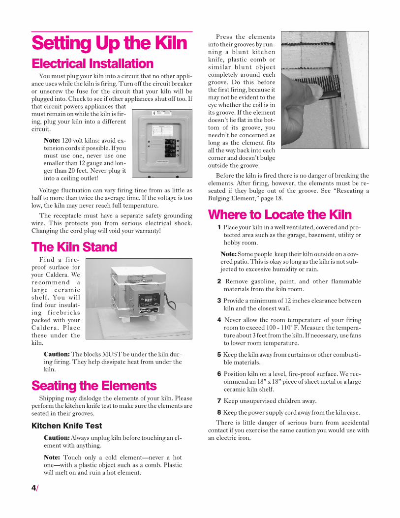
Press the elementsinto their grooves by run-ning a blunt kitchenknife, plastic comb orsimilar blunt objectcompletely around eachgroove. Do this beforethe first firing, because itmay not be evident to theeye whether the coil is inits groove. If the elementdoesn’t lie flat in the bot-tom of its groove, youneedn’t be concerned aslong as the element fitsall the way back into eachcorner and doesn’t bulgeoutside the groove.
Before the kiln is fired there is no danger of breaking theelements. After firing, however, the elements must be re-seated if they bulge out of the groove. See “Reseating aBulging Element,” page 18.
Where to Locate the Kiln1 Place your kiln in a well ventilated, covered and pro-
tected area such as the garage, basement, utility orhobby room.
Note: Some people keep their kiln outside on a cov-ered patio. This is okay so long as the kiln is not sub-jected to excessive humidity or rain.
2 Remove gasoline, paint, and other flammablematerials from the kiln room.
3 Provide a minimum of 12 inches clearance betweenkiln and the closest wall.
4 Never allow the room temperature of your firingroom to exceed 100 - 110° F. Measure the tempera-ture about 3 feet from the kiln. If necessary, use fansto lower room temperature.
5 Keep the kiln away from curtains or other combusti-ble materials.
6 Position kiln on a level, fire-proof surface. We rec-ommend an 18” x 18” piece of sheet metal or a largeceramic kiln shelf.
7 Keep unsupervised children away.
8 Keep the power supply cord away from the kiln case.
There is little danger of serious burn from accidentalcontact if you exercise the same caution you would use withan electric iron.
4/

Basic OperationAccessoriesCeramic Shelves & Posts
Shelves and postsare fireclay that hasbeen fired to a highertemperature than willbe encountered inyour kiln. Ware isplaced on the shelves.Shelves can bestacked using posts.
Glass Separator & Kiln WashGlass separator and kiln wash are mixtures of finely
ground minerals that willnot melt and fuse to-gether at high tempera-tures. They prevent glassand ceramic glaze fromsticking to shelves andthe firebrick bottom.The main difference be-tween glass separatorand kiln wash is that theseparator is ground morefinely to leave a smoothback to glass pieces laidon the shelf.
As powders, glass separator and kiln wash have an unlim-ited shelf life. Do not breathe the powder when mixing.
Note: CAUTION: If glass separator or kiln washcontact a heating element, that element will burnout in the next firing. NEVER apply glass separatoror kiln wash to the walls of the firing chamber or tothe kiln top.
Haik BrushThe haik brush is used to apply
glass separator to the kiln shelf ina smooth, thin layer . Thesmoother the glass separator, thesmoother the underside of theglass.
Alumina HydrateDelicate silver or gold clay shapes may need extra support
during firing to prevent warping. Place these shapes in a thinlayer of alumina hydrate inside a small ceramic bisque bowl.Do not breathe alumina hydrate.
StiltsStilts are points embedded in a ceramic base. The points
separate enameling and glazed ceramics from the shelf andfirebrick bottom.
Enameling RacksEnameling is the art of firing glass onto metal. The metal
shapes are loaded onto a high temperature wire rack. Theenameled pieces and wire rack are loaded into a hot kiln,fired for just a few minutes, and removed red hot. To loadand unload the rack safely, use an enameling fork.
The heating element under power is dangerous. Do nottouch the element with anything! Turn the kiln switch offbefore inserting the enameling fork into the firing chamber.
Safety GlassesWear clear safety glasses
when cutting or chipping glass.Wear firing safety glasses whenlooking into a hot kiln, such aswhen checking the progress ofglass.
Important GuidelinesThe Clicking Noise
Do not be concerned if your kiln makes a clicking soundduring firing. Digital kilns contain a relay, which sendspower to the element. The relay clicks as it cycles on and offto maintain the correct temperature. Manual kilns use an in-finite control switch that clicks as it cycles on and off.
Manual Kilns: The Infinite Control SwitchThe manual kilns use an in-
finite control switch. A bime-tallic timer inside the switchcycles on and off to regulateheating. The higher the switchsetting, the longer the elementstays on during each cycle. OnHigh, the element stays oncontinuously. This is why theclicking noise stops after theswitch is turned to High.
Check ThermocoupleYou will find a rod, called the thermocouple, extending
into the firing chamber. Both manual and digital kilns use athermocouple. The digital controller senses temperature byreading a small voltage from the thermocouple. If the tip ofthis rod is pushed out of the firing chamber, the kiln will as-
/5
Wear firing safety glasses and protective gloves.
The pilot light serves as thepointer mark for the infinite con-trol switch knob. The pyrometershows temperature.

sume that the firing chamber iscold. On digital kilns, this will re-sult in an over-fire. When loadingthe kiln, check that the rod ex-tends into the firing chamber by1” or more.
Vacuum the KilnClean the kiln interior before
firing glass, enameling, or ceramic glaze. (Cleaning is notnecessary when firing silver or gold clay.) Use a soft brushnozzle on a vacuum cleaner. Vacuum the element grooves toremove debris, which could damage the element.
Removing Hot WareTo remove hot ware
from the kiln, turn offthe kiln. Tilt the kilnupward about 1” by lift-ing the electrical box.Careful ly s l ide anenameling fork underthe shelf or enamelingrack. Place the hotshelf/rack onto a largeceramic kiln shelf in front of the kiln. Wear thick work gloves.
Firing Log BookRecord the following information in a firing log book:
� Date� Digital: Firing speed and Hold or Ramp/Hold program� Starting time� Total firing time� Type of pieces� Firing results
As you gain experience, you will find a wealth of informa-tion in your firing records.
Low Temperature Holds (Digital Kilns)A low temperature hold (i.e. 200° - 300°F) is more diffi-
cult to maintain than higher temperature holds (1400° -1700°F). At low temperatures, turning on the heating ele-ment affects firing temperature to a larger degree than athigh temperatures.
When holding at a low temperature, heat the kiln slowly.Otherwise the temperature may overshoot the hold temper-ature before the element turns off.
Avoid Contaminating the Heating ElementContact with silica or silica bearing compounds, such as
kiln wash, glass separator, alumina hydrate, glass, enamelingpowder, and ceramic glaze, will ruin the heating element.
Note: If glaze or glass drips onto a firebrick wall, digout the glaze with a screwdriver. Otherwise it maymelt into a brick groove during the next firing andruin the element.
The Effect of Silver Residue on GlassFiring silver clay leaves traces of silver in the firebricks.
Sometimes there is enough silver residue in the kiln to affectglass colors. For instance, green might turn yellow.
Note: Before firing an important glass piece in akiln used for silver clay, perform color tests. Firesmall samples of each glass color on a base sheet ofclear glass. See pages 7 - 9.
Loading the KilnPlace Ware on the Kiln Bottom oron a Protective Shelf
Ceramics can befired directly on thefirebrick bottom oron a shelf. Fire glassonly on a shelf ormold, never directlyon the brick bottom.
Types of shelvesand containers:
Fireclay ShelfCeramic fireclay shelves, available from Paragon, protect
the firing chamber bottom and provide a smooth surface.Use a ceramic shelf in your kiln to fire ceramics, glass, andchina painting.
Insulating FirebrickPiece
Insulating firebricksare porous, light-weight,and can be shaped to sup-port delicate silver clay de-signs. Carve the firebrickwith a knife or hacksaw.
Ceramic BowlYou can purchase an unglazed, small ceramic bisque
bowl from a ceramic supply store. The bowl will last throughmany firings. Use it to hold alumina hydrate for silver claypieces. You can also shape hot glass by slumping it into thebowl.
Applying Glass Separator or Kiln WashThe kiln shelf, kiln bottom, and sagging mold must be
coated with glass separator tokeep glass or ceramic glaze fromsticking to them.
A coat of glass separator orkiln wash will usually lastthrough several firings. Whenthe shelf coating begins to crackor chip, apply a fresh coat.
When recoating a shelf, re-move most of the old coatingwith grit cloth (available fromParagon). This is an abra-
6/
Separator lasts through sev-eral glass firings. Apply newseparator when the old coatbegins to flake.

sive-coated mesh that allows residue to pass through. Youcould also use coarse sandpaper. Removing the old coatinggives you a smooth surface to start with. Then recoat theshelf using the following directions. (Both glass separatorand kiln wash will be referred to as “separator.”)
Caution: Keep separator away from the elements.
1 Mix the separator with water following the directionson the bag. Stir.
2 Use a haik brush or a softpaint brush to apply theseparator to the shelf.(The haik brush is easierto use because it laysdown a more even coat-ing.) Each time you dipyour brush into the sepa-rator mixture, swirl thebrush around the bottomof the container. This is because the separator settlesquickly. Use two or three thin coats changing the di-rection of the brush stroke 90° with each coat.
3 Dry the shelf before firing. To speed drying, place theshelf on 3 - ½” posts inside the kiln. Heat at full rateto 300°F/148°C and hold for 15 - 30 minutes. Thenturn off the kiln and leave the shelf inside.
4 After the separator has dried and your shelf is cool,you can smoothen the separator further by rubbingyour hand lightly over the shelf. The smoother theseparator, the smoother the back side of the glass.
A coat of glass separator will usually last several firings.The lower the fusing temperature, the more firings you canget from one application of separator.
Using PostsCeramic posts support ceramic fireclay shelves.
� When firing glass, place 3 - ½” posts under the ceramicshelf on the firebrick bottom. This aids air circulationaround the shelf.
� You can fire two or more ceramic shelves in your Caldera.When you load multiple shelves, use a slower firing rate.This aids heat distribution.
� Always fire glass on a shelf. Ceramics can be fired on thebrick bottom as well as on shelves.
Venting the KilnSome types of ware, such as
ceramics, contain impuritiesthat burn off during firing.These impurities must be re-leased from the kiln at the begin-ning of the firing. Otherwisethey can affect the quality of theware. To vent the kiln, place a ½”post under the top.
Glass Fusing &Slumping
You will probably fire mostly stained glass, but you canalso fire standard float (window) glass. Some types of floatglass devitrify (form a dull, frosty surface) when fused.
Caution: Never fire tempered glass. It could ex-plode if heated inside a kiln.
Basic Glass ToolsReservoir Glass Cutter uses a reservoir of oil to lu-
bricate the cutter wheel.
Running Pliers are for cutting large pieces of glass.
Breaking Pliers are for cutting small strips.
Grozing Pliers shape the glass by chipping away theedges. They are often used when the score line doesn’t breakclean. Note that rough edges will become smooth when firedto fusing temperature.
How to Cut GlassNote: IMPORTANT! Wear safety glasses whencutting or chipping glass.
1 Lay the glass on a clean surface. Mark off the cut witha grease pencil or felt-tip pen. A small mark on eachend of the glass will do. Lay a wooden straight edgeover the glass and line it up with the marks you justmade.
/7

2 Hold the straight edge firmly and score the glasswith the glass cutter. Press just hard enough so thatthe scoring noise sounds steady and unbroken.
3 Place the straight edge under the glass so that anedge is lined up with the score line you just made.Press down on the glass. It will break cleanly.
Fusing Compatibilityof Glass
When glass changes temperature, it expands and con-tracts. The rate at which glass changes size is called the coef-ficient of thermal expansion. If you fuse two glass pieces to-gether and one changes size faster or slower than the other,the fused piece may crack—even several months after fus-ing.
When different glasses have a close enough coefficient ofexpansion to fuse successfully, they’re called fusing compati-ble. Buy glass labeled fusing compatible. Or fuse glass thathas been cut from the same sheet, which guarantees com-patibility.
Fusing Compatibility Test1 To test glass for compatibility, fuse small ½” square
sample pieces of different glasses onto a larger basepiece of clear transparent. The base should extendbeyond the small sample pieces by half an inch oneach side. Include, among the sample squares, apiece cut from the clear transparent base.
2 Heat the glass to a temperature that completelyrounds the edges of the small sample pieces.
3 After the glass cools, place a polarizing filter underthe glass and another filter over the glass. Look atthe glass with light shining through it (hold it over alamp). Turn one of the filters until the filters are attheir darkest.
Results of the TestIf you see a halo around the edges of the small glass sam-
ples, the glass is not compatible. If you see no halo, the glassis fusing compatible.
Why did we include a sample square cut from the basetransparent glass? It tests for annealing. A halo around thatpiece means the glass was not annealed properly. Performthe test again, this time cooling more slowly through the an-nealing range.
The Annealing RangeEach type of glass has a temperature range that it must
pass through slowly when it cools. This is called the anneal-ing range. This slow cooling gives hot glass time to releasethe stress of cooling. If you cool the glass too fast through theannealing range, it will break.
The larger and thicker the glass, the slower it must passthrough its annealing range. You cannot over-anneal, so err
on the side of caution if you aren’t sure how long to anneal.Small projects such as earrings rarely need annealing time asthey cool.
Cleaning and Gluingthe Glass
Grease, dirt, and finger-prints etch permanentlyinto the glass during firing.Clean the glass with glasscleaner (the type withoutsilicones), rubbing alcohol,or even plain water just be-fore assembling the pieceson the kiln shelf.
Use white glue, such asElmer’s diluted 1:1 with wa-ter, to hold the glass piecestogether after you placethem on the kiln shelf. Usethe glue sparingly. Glue isespecially important whenfusing wire into the glass.The glue prevents the glassor wire from moving out ofplace before they fuse. The glue disappears during firing.
Avoid using glue on the coated side of dichroic glass. Ifyou lay dichroic glass carefully onto the piece, glue is unnec-essary, so avoid it altogether if you do not know which side ofthe dichroic is coated.
Load Glass Into the KilnAir should circu-
late between the shelfand the bottom of thekiln, so place three orfour 1/2” posts in thekiln. Lay the shelfover the posts.
Firing the GlassFiring speed varies depending on the size and thickness
of the glass project. The thicker and larger the project, theslower you must fire it. Otherwise the glass may crack. Smalljewelry pieces, such as earrings, can usually fire at full speed.
Viewing the Glass During FiringWatch the glass by moving the top over just enough to
where you can see inside the kiln. Look for several seconds ata time. Wear firng safety glasses and protective gloves.
Note: When you move the top, do not slide it, or dustparticles could land on the glass. Gently lift it
8/

slightly. With every firing, be sure you are near thekiln before the expected shut-off time.
Digital KilnsThe first time you fire a particular brand or type of glass,
program the controller for a higher temperature than the es-timated fusing temperature. Shut the kiln off when the glassfuses the way you want. Make a note of the shut-off tempera-ture. For future firings, program the kiln for that rate andtemperature.
Manual KilnsShut the kiln off when the glass fuses the way you want.
Make a note of the shut-off temperature shown on the py-rometer. For future firings, begin watching the glass 100° -200° below the final temperature.
Annealing the GlassThe annealing range for most glasses is between
950°/510°C and 700°F/371°C. Cool slowly through thisrange. Leave the top closed, rather than vented, during cool-ing. This will slow the cooling enough for most projects.
Digital Kilns: If you need even slower cooling, programa separate segment for cooling. See the kiln’s digital control-ler manual.
Manual Kilns: If you need even slower cooling, turn thekiln on again for about 30 minutes while the glass anneals.Use a medium switch setting.
Note: For safest cooling, leave the ware inside thekiln until the kiln reaches room temperature. If youremove the ware too soon, the sudden temperaturechange can crack the piece.
Rapid Cooling of Small PiecesTo remove small pieces, such as glass jewelry, before they
have cooled completely, remove the shelf also. Leave thepieces on the shelf until they reach room temperature. Theheat in the shelf will help prevent them from cooling tooquickly.
To remove hot ware from the kiln, turn off the kiln. Tiltthe kiln upward about 1” by lifting the electrical box. Care-fully slide an enameling fork under the shelf. Place the hotshelf onto a large ceramic kiln shelf in front of the kiln. Wearprotective gloves.
Annealing Flame-WorkedGlass Beads
Glass is sensitive to breakage as it cools through the an-nealing range. This is approximately 950°F/510°C through700°F/371°C. The larger the piece, the slower it must cool.
To safely cool flame-worked glass beads, anneal them inyour kiln using the optionalBead Collar.
1 Place the Bead Collar be-tween the kiln and theseparate bottom. The kilntop should be in place.
2 Digital Kilns: Programthe control ler inRamp-Hold for the fol-lowing two segments.(See the separate digitalcontroller manual.) Ifyour bead making session will be longer than threehours, program a longer hold time in segment 1.
Rate Temp.Segment °F/°C °F/°C Hold
1 1799/999 1000/537 03.00
2 400/222 700/371 00.00
Fire the kiln. When it reaches 1000°F/537°C, it will main-tain that temperature for three hours.
Manual Kilns: Fire thekiln with the switch on High. At900°F/482°C, lower the switchsetting to Med. Then keep ad-justing the switch to maintain atemperature of 1000°F/537°C.
3 At 1000°F/537°C, the kiln isready to receive the beadmandrels loaded with hotbeads. Allow a freshly fin-ished bead to cool slightlybefore inserting. This is toprevent the bead from flat-tening on one side when itis placed inside the kiln.
Open the bead door. Insert the mandrels as you completethe beads. Leave the door ajar with the end of the bead man-drel extending outside the kiln.
4 Digital Kilns: When you have finished the batch ofbeads, perform a Skip Segment. This will end thetemperature hold and begin segment 2. The kiln willslowly cool through the annealing range. ManualKilns: Turn the kiln off and let it cool slowly.
After the kiln shuts off, leave the beads in place. Do not re-move them until the kiln has reached room temperature.
/9
To look at the glass during firing, move the top slightly. Look insidethe kiln for a second or two. Wear firing safety glasses and gloves.

Enamelingon MetalHow to Load the Kiln
1 Remove the top. Place several ½” posts on the floorof the kiln.
2 Lay a wire enameling rack on top of the posts. If theenameled piece is bare on the back, place the piecedirectly onto the rack. If the back side of the piece isenameled, support the piece with a stilt on top of therack.
3 Lower the toponto the kilnand fire. (Seefiring instruc-tions, page 11.)
4 To remove thepiece, turn offthe power. Tiltthe kiln upward about 1” by lifting the electricalbox. Slide in an enameling fork and remove theenameling rack.
5 Lower the kiln. Turn the power back on if you wishto enamel another piece.
Preparation of the CopperEnamels come in transparent or opaque. They can be
purchased directly from Thompson Enamel, P.O. Box 310,Newport, Kentucky 41072. Their Lead Free Enamels comeready to use: no enamel washing is needed.
Start with one of the many pre-shaped copper forms avail-able, or shape and trim the copper to your own design.
1 Heat the copper on an enameling rack to about1400°F/760°C to burn off oil or grease. Heat thecopper to just until smoke from oil or grease stopscoming off the metal and its color has changed to apurple-red-pale green iridescence that movesacross the copper. This indicates that the greasehas vaporized. Do not fire the copper any longer thanthis point. Otherwise excess fire scale will form,making thenext cleaningstep difficult.
2 After the coppercools , brushany loose scalefrom the cop-per. Use abrush or papertowel , being
sure that you do not put any grease or oil onto thecopper, such as fingerprints. Clean the copper witha 3M Scotch-Brite® pad. This pad does such a goodjob that in most cases no further cleaning will be re-quired. Additional copper cleaning products areavailable in the Thompson Enamel Catalog, includ-ing Sparex No. 2.
It is best to clean the copper just before you decorate it. Ifyou wait too long to decorate after cleaning, the copper couldget dirty again.
Decorating the CopperCounter Enameling
Most enameled pieces should be counter enameled onthe back side. This gives the piece a much more finishedlook, it eliminates a great deal of fire-scale cleaning, and itcontrols the chipping and cracking that can result from thedifferent rates of expansion and contraction in copper andenamel after the enamel has been fired.
Counter or backing enamel, a mixture that gives a mot-tled effect, can be used for counter enameling. Or you canuse regular enamel. Counter enamel is applied by the siftingmethod described next.
When firing counter enamel, underfire it so that the firescale on the front of the piece isn’t too difficult to remove.You can purchase a masking preparation from your supplierto help prevent fire scale. You must place the piece on a stiltwhen firing the other (front) side of the piece. The stilt pre-vents the back of the counter enameled piece from stickingto the enameling rack.
Applying EnamelsApply enamel over a clean sheet of paper so you can pour
the excess back into the bottle for reuse. Transparent enam-els should be applied in several thin coats. Transparentenamels can be mixed with fairly good results. If opaqueenamels are mixed, however, a grainy effect results. The twobasic methods of applying enamels are sifting and spatula.
Sifting EnamelSpray or brush Thompson holding agent onto the copper.
Then sift a 1/32” layer of enamel onto the copper. Use a #60mesh sifter. If the coat is too thin, you can easily add another
10/
coat after firing. But a coat that is too thick will bubble andcrack. The enamel must dry completely before firing.
Spatula or Inlaid MethodYou can use this method to decorate a small area with
many different colors. Using a diluted solution of Thompsonholding agent, dampen the enamels just to the saturationpoint, and maintain this moisture while working with theenamels. Apply the enamels onto the copper with a smallspatula, and spread them out with a spreader to a coat ofabout 1/32” thick. Lines of contact can be formed by thespatula blade. Then spray the enamels with the holdingagent to keep the grains of enamel in place. Allow the enamelto dry completely before firing.
Firing Enamel1 Heat the kiln to 1450°F/787°C for most enameling.
Digital kilns: Use a Single Segment. Please see yourdigital controller instruction manual.
Rate Temp.Segment °F/°C °F/°C Hold
1 1799/999 1450/787 01.00
Note: Hold time should be the length of time youwill be firing enameling pieces. In the above exam-ple, hold time is one hour.
Manual Kilns: Fire the kiln with the switch on High. At1300°F/700°C, lower the switch setting to Med. When thetemperature reaches 1450°F/787°C, keep adjusting theswitch to maintain that temperature.
2 Lay the copper shape on an enameling rack. If thepart that touches the rack is enameled, place a stiltunder the copper. Some bowls or other shapes haveenameled sides that might run during firing. Theseshould be fired with a stilt even if the piece has a plainbottom. Use an enameling fork to place the rack intothe kiln.
Note: Firing should take about three minutes andrequires undivided attention!
3 Look at your piece every 15 seconds by tilting the kilnby the switch box about 1”.
4 When the copper piece appears a rosy red and theenamel is smooth, turn off the power to the kiln. Liftthe kiln about 1” and remove the enameling rackwith an enameling fork. Lower the kiln. Turn thepower on if you want to make more enameling pieces.
5 Place the rack on a steel pad or ceramic shelf and let itcool completely.
6 After counter enameling, you will need to clean thefire scale off the front of the piece. A 3M ScotchBrite® pad works well for this. Then clean it withThompson Sparex No. 2.
CeramicsPyrometric Cones
Pyrometric cones are small pyramids of clay and mineraloxide that soften and bend when exposed to heat. They indi-cate when ceramic ware has fired to maturity.
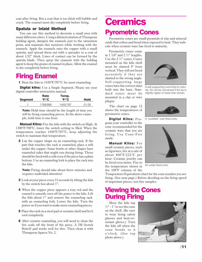
Pyrometric cones comein 1 1/8" and 2 ½” lengths.Use the 2 ½” cones. Conesmounted on the kiln shelfmust be slanted 8° fromvertical. They will not bendaccurately i f they areslanted to the wrong angle.Self-support ing largecones have the correct slantbuilt into the base. Stan-dard cones must bemounted in a clay or wireplaque.
The chart on page 12shows the temperatures ofpyrometric cones.
Digital Kilns: Pro-gram your controller to thecone recommended for theceramic ware that you arefiring. Use Cone-Firemode.
Manual Kilns: Forsmall ceramic pieces, suchas figurines, fire at a rate ofabout 400°F/222°C perhour. Ceramic jewelry canbe fired even faster. Fire tothe temperature shown inthe 108°F column of theTemperature Equivalents chart for the cone number you arefiring. (See next page.) Before deciding on the firing speedof important pieces, test fire samples.
Viewing the ConesDuring Firing
Move the kiln top½” - 1” to see the coneon the shelf. (Be sureto wear firing safetyglasses and heat-re-sistant gloves.) Turnthe kiln off when thecone bends to 6o’clock. (See topphoto above.)
/11
A self-supporting cone fired to matu-rity. Do not be concerned if the tip isslightly higher or lower than shown.
A “puddled” over-fired cone.
An under-fired cone.

Firing OverglazeOverglaze is decoration applied over fired glaze or pol-
ished porcelain bisque. Overglazes include china paints,gold, and luster, which fire from 022 to 014.
Load overglazed ware the same way you would load ce-ramic glaze. Use stilts and make sure ware is not touchingother ware. Ware must be completely dry before firing.
China paints will crack or peel if applied heavily. Applyseveral light coats instead, firing between each, until you getthe shade you want. Not all china paint colors reach maxi-mum color saturation at the same temperature even whenfired on the same ware. So you must know which colors youshould fire first at higher temperatures to prevent burningout the original colors in later firings. For example, reds ma-ture at a lower temperature than other colors and are firedafter the other colors have been fired. Reds and yellowsshould not be fired side by side. Colors also mature at a lowertemperature on ceramic pieces than on porcelain or hardchina. Check the overglaze manufacturer’s literature for thecone to use with each color and type of ware.
Vent the kiln during the first hour of firing by placing a ½”post under the kiln top. Allow kiln to cool to room tempera-ture before opening the kiln.
Firing Low Fire GreenwareLow-fire greenware has a firing range from cone 06 to 02.
The greenware must be bone dry before firing. Otherwise, itwill crack or even explode in the kiln. Check for dryness bytouching to cheek or inside of wrist. Moist ware will be cold.
Low-fire greenware may be stacked so that it toucheseach other. It can be loaded without stilts. Load pieces di-rectly on the firebrick bottom.
Ware should be fired in the position in which it will beused when finished, except for large pieces with flat, verticalsurfaces such as wall plaques and clocks. These should befired flat to prevent warping. Pieces to be used togethershould be fired in place, such as a box with its lid, to ensure agood fit.
Low-fire greenware firing is simple. Just be certain thegreenware is fired to the pyrometric cone recommended bythe clay supplier. If the greenware is not fired hot enough,the piece will absorb moisture after it has been glaze-firedcausing the glazed surface to crack. This is called “crazing,”and is most often due to underfired greenware. To helpeliminate crazing, fire greenware at least one cone hotterthan glaze, and even hotter if glaze can still be applied easilyto the hard bisque. While glaze may be applied to greenwareand fired once, separate firings produce better quality, so wedo not recommend single firing of greenware and glaze.
Vent the kiln during the first hour of firing by placing a ½”post under the top. Allow kiln to cool to room temperaturebefore opening.
12/
°F Temperature Equivalents For OrtonSelf-Supporting Pyrometric Cones
Cone Self-Supporting Cones Pre-FireNumber Color
Heated at: 27° F 108° F 270° FPer Hour* Per Hour* Per Hour*
022 — 1087 1094 Green
021 — 1112 1143 Fuschia
020 — 1159 1180 Orange
019 1213 1252 1283 Yellow
018 1267 1319 1353 White
017 1301 1360 1405 Pink
016 1368 1422 1465 Light Blue
015 1382 1456 1504 Violet
014 1395 1485 1540 Gray
013 1485 1539 1582 Green
012 1549 1582 1620 Fuschia
011 1575 1607 1641 Orange
010 1636 1657 1679 Dark Red
09 1665 1688 1706 Dark Red
08 1692 1728 1753 Dark Red
07 1764 1789 1809 Dark Red
06 1798 1828 1855 Dark Red
05 1/2 1839 1859 1877 Dark Red
05 1870 1888 1911 Dark Red
04 1915 1945 1971 Dark Red
03 1960 1987 2019 Dark Red
02 1972 2016 2052 Dark Red
01 1999 2046 2080 Dark Red
1 2028 2079 2109 Dark Red
2 2034 2088 2127 Dark Red
3 2039 2106 2138 Dark Red
4 2086 2124 2161 Gray
5 2118 2167 2205 Green
5 1/2 2133 2197 2237 White
6 2165 2232 2269 Fuchsia
7 2194 2262 2295 Orange
8 2212 2280 2320 Yellow
9 2235 2300 2336 White
10 2284 2345 2381 Pink
*Rate of temperature increase during last 90 - 120minutes of firing. Tables by courtesy of the EdwardOrton, Jr. Ceramic Foundation.

Firing Low Fire GlazeLow fire glazed ware must not touch each other, the floor,
or a shelf in your kiln during firing. If this happens they willpermanently bond together by melted glaze and be ruined.
Clean the firing chamber before each glaze firing. Wipesurfaces with a clean, damp cloth or vacuum with the softbrush nozzle attachment of a vacuum cleaner.
Use stilts to support low-fire glazed ware during firing.The shelf tops and kiln floor MUST be kiln washed with allpurpose, high fire kiln wash for protection from glaze drops.
Glazed pieces must be thoroughly dry before firing andshould not be fired with greenware unless both mature at thesame cone. Check to make sure that first, no two pieces ofglazed ware are touching each other, the kiln walls, the flooror the shelf; and second, that the underside of the kiln shelfis clean before you place it over glazed pieces. Any dust fall-ing on your ware will cause pinholes.
You can prevent glazed pieces from sticking to the shelfor kiln bottom by “dry footing.” To “dry foot” a piece, re-move all glaze from the portion of the piece that will rest onthe shelf. Using a wet sponge or a piece of grit cloth, clean offthe glaze from the bottom of the ware and slightly above thebase so that it will not run down and touch the base. Dry foot-ing should not be used for low-fire glazed pieces that will beplaced in water while used or cleaned.
During the first hour of firing, vent the kiln by placing a½” post under the top. Wait until the kiln has cooled to roomtemperature before opening the kiln.
Remove the stilts from the ware after firing by breakingthe thin film of glaze holding them. Handle with caution; theglaze is sharp where the points touch. Remove the sharp stiltedges by rubbing with a stilt stone or electric grinder.
Firing Porcelain GreenwareLoading porcelain greenware is similar to loading glazed
ware, since both will stick to anything during firing.Greenware must be completely dry before firing, includingthe joints on pieces that are attached. If a piece is broken be-fore firing, mend the break but do not attempt to fire it untilthe mend is also bone dry. Damp greenware or dampmended areas will form bumps on the fired ware.
Stilts CANNOT be used to support porcelain greenware.They would embed into the porcelain. To protect porcelainfrom sticking to the shelves or kiln floor, apply a coat of highfire kiln wash to the shelf tops and brick bottom. Then placeyour ware directly on the kiln washed surfaces.
Note: Never use ceramic kiln wash in a kiln that willever be fired to porcelain temperatures, as the ce-ramic kiln wash will harden at high temperaturesand be impossible to remove.
Pieces of ware that are to be used together must be firedtogether, such as a box and its lid. Dry all purpose, high firekiln wash can be used to separate these pieces during firing.
Wet kiln wash would be too difficult to remove. Pieces likelyto warp in firing should be supported by rolls of porcelainclay shaped to fit the objects at points of strain. Apply dry sil-ica or high fire kiln wash to the points of contact to preventsticking. Before firing, the support rolls must also be dry.
Since a kiln is slightly hotter near its sidewalls, the side ofthe ware next to the walls will tend to shrink more than theopposite side. This can be used to your advantage with por-celain figurines that tend to warp during firing. Turn the in-clined side of the figure away from the elements so the heatcan help hold the piece straight.
Make sure cones on the shelf are clearly visible. At porce-lain temperatures, they are difficult to see. Vent the kiln dur-ing the first hour of firing by placing a ½” post under the top.Wait until kiln cools to room temperature before opening it.
Firing Porcelain GlazePorcelain pieces that have been fired together in the
greenware firing cannot be fired together in the glaze firing.Both pieces must be “dry footed.” Since shrinkage has al-ready occurred in the greenware firing, the pieces will still fiteven when fired separately in the porcelain glaze firing. Stiltsmust not be used to support porcelain. Porcelain softens dur-ing firing, and stilts would embed into porcelain. Make sureyour shelves and kiln bottom have a good coat of kiln washbefore firing porcelain.
If a piece of ware had to be supported in the porcelainbisque fire, it will stand alone in the glaze fire. The lowertemperature will prevent sagging.
Vent the kiln during the first hour of firing by placing a ½”post under the top. Wait until kiln cools to room temperaturebefore opening the kiln.
Firing StonewareGreenware or Glaze
Stoneware is made from vitrifiable clays with a firingrange of cones 2 - 10. It has a wide range of colors and tex-tures and is popular with the potter because of its excellentthrowing qualities. Usually the greenware is fired below ma-turity, and on the second firing, the clay and glaze mature to-gether to form an integrated body-glaze surface.
Like porcelain greenware, stoneware is placed directlyupon the kiln-washed shelves in the greenware firing.
Glazed stoneware must not touch any other ware andmust be dry footed before you place it on a kiln-washed shelfor kiln bottom. Never stilt stoneware during either firing.
Glaze TestingMake batches of uniform clay shapes, such as circles or
triangles. Each shape should have a smooth section and tex-tured section. Glaze the test shapes. Prop them up verticallyinside a dish and fire them. Keep detailed records in a glazenotebook. Save the test samples. They will be valuable later.
/13

Silver & Gold ClayWith silver clay, it is possible to shape intricate, free-form
silver jewelry in minutes—even as a beginner. (The clay isalso available in gold; for simplicity we will refer to both met-als as “silver clay.”) At the time of printing, the silver claybrands available were Art Clay Silver and Precious MetalClay.
Silver clay looks and feels like modeling clay. It is formedwith simple tools such as a tooth pick, small knife, and razorblade. Its surface is pliable and accepts impressions fromobjects such as leaves, coins, and coarse fabrics. After the sil-ver clay is formed, it is fired in a kiln. The recommendedtemperature and hold time are included with the silver clay.
Forming and firing silver clay is simple. There is nothingmysterious about making silver clay jewelry. The clay ismade of micron-size silver (or gold) particles held in an or-ganic binder. During firing, the binder burns away. The sil-ver particles then fuse together forming real silver. Since thebinder disappears, there is a certain amount of shrinkageduring firing. Shrinkage varies depending on the type of sil-ver clay you use.
Drying TimeSmall, thin silver clay pieces can be placed into the kiln
while still moist, and fired. Thicker pieces need time to dry.Otherwise they may warp during firing.
To be on the safe side, give the silver clay plenty of time todry. As you gain experience, you will know just how muchdrying time each type of piece needs. You can speed dryingwith a hair dryer.
Loading the KilnSilver clay pieces that have a flat side can be placed inside
the kiln directly onto a shelf. Use a soft ceramic fiber shelf. Itcushions the clay silver.� Silver clay pieces can be close together, but they must not
touch.� Place the soft ceramic fiber shelf directly onto the firing
chamber bottom.� Do not coat the ceramic
fiber shelf with kilnwash or glass separator.
� You can also place thesilver clay on a piece ofceramic fiber batting.
Alumina HydrateRounded, hollow, or
other delicate shapes mayneed support to preventcollapsing. You can laythese pieces onto a moundof alumina hydrate.
If the piece needs only shallow support of ¼” depth orless, pour the alumina hydrate onto a ceramic fireclay shelf.Support the fireclay shelf on 3 - ½” posts to aid heat flow un-der the shelf.
If the silver clay shape needs deeper support, pour thealumina hydrate into an unglazed ceramic bisque bowl.These are available at ceramic supply stores.� Place the ceramic bowl directly onto the kiln bottom.� NEVER use a glazed bowl to hold the alumina hydrate. If
the glaze runs, it will embed into the firebrick bottom.
Caution: Avoid breathing alumina hydrate dust.Alumina hydrate can destroy the heating element oncontact. If it spills onto the firing chamber, removewith a vacuum cleaner.
Venting the KilnSilver clay by itself needs no venting. Load the kiln, lower
the lid, and leave it closed until the clay silver is ready to re-move.
The kiln needs venting ifyou fire ceramics with theclay silver, or if you makehollow objects that containa core of organic materials.In those cases, vent the lidduring the first hour of fir-ing by placing a ½” post un-der the kiln top.
Paper maché and paper clay are good core materials. Donot use wax or styrofoam as a core. They emit harmfulfumes.
Rate, Temperatureand Hold
Each brand of silver clay fires to a specific temperatureand hold time. This information is available from your silverclay supplier.
Note: Hold time is the lenth of time that the recom-mended temperature is maintained in the kiln. Donot fire longer than the recommended hold, or thesilver will begin to overfire.
Besides selecting a temperature and hold time on yourkiln’s digital controller, you will also need a firing rate. (Seethe separate digital controller instruction booklet.) Select aFull Power rate if you are firing silver clay alone. If you fireglass or ceramics with the silver clay, select a rate best suitedfor the glass or ceramics.
Note: Do not place silver clay into a kiln that is al-ready hot unless the clay is completely dry. The kilnshould be no hotter than 500°F/260°C when insert-ing the silver clay.
14/
Place the clay silver on a ceramic fi-ber shelf, which has a soft surface.

After the kiln begins firing, leave the top closed. Do notlift the top until it is time to remove the clay. Visual inspec-tion of the clay during firing is unnecessary.
If you are firing glass with the silver clay, on the otherhand, you will needto check the fusingprogress of the glassby moving the kilntop ½” or more andlooking inside.Look for just a sec-ond or two. As yougain experience, youwill be able to pro-gram the correcttemperature for the silver clay and glass combination, elimi-nating the need to visually check the glass.
Manual Kilns: Select the type of silver clay that has theshortest hold time. You will need to adjust the switch duringhold to correct the temperature as it drifts.
Cooling TimeAfter the clay silver has fired to completion, you can lift
the top an inch to speed cooling. If you are firing stones,glass, or other materials with the silver clay, it will be safer toallow the kiln to cool slowly with top down. Remove the piecewhen the kiln reaches room temperature.
Combining Silver ClayWith Other Materials
There are two ways to fire silver clay with other materialssuch as glass:� Fire the silver clay first by itself. After you have cleaned
and polished the silver clay, fire it a second time withglass.
� Fire the silver clay and other materials, such as a stone,together in a single firing.
Glass is often fired with the silver clay in a single firing.Many types of glass, however, will melt at silver clay tempera-tures. If you are going to combine glass and silver clay in asingle firing, test a small sample of the glass. To do this, firethe glass during a silver clay firing, keeping the glass sepa-rate from the silver clay piece. (This way you won’t ruin thesilver clay piece.)
Place the pieces on a ceramic fireclay shelf. You must coatthe shelf with glass separator, or otherwise the glass samplewith embed into the shelf.
If the glass sample survives the firing, you can fire thattype of glass with silver clay in a single firing. Note, however,that different types of glass fire to different temperatures.Every time you fire a different type of glass, be sure to test.
Firing MistakesSilver ClayCracks that appear in fired silver clay may be due to too muchwater in the silver clay before it was fired. Another cause iscareless handling of a dried piece before firing. To repair, fillthe crack with silver clay and fire again.
Brittle Silver clay will not reach full strength if underfired.You may be able to save the piece by firing again to the correcttemperature and hold.
Too Much Shrinkage When silver clay is overfired, itshrinks too much and loses detail. You may need to replace thethermocouple on the digital kiln if the temperature isinaccurate.
GlassGlass Cracking is caused by heating or cooling too fast orfusing incompatible glass. Not enough glass separator on theshelf can also cause glass cracking.
Most problems in fusing are caused by rushing the firing.The glass must change temperature slowly during the criti-cal temperature range of 100° - 500° F. This critical rangeapplies to both heating and cooling.
The second critical temperature range is annealing,which is the cooling range of 950° - 750°F average. Cool theglass slowly during this range so the stress in the glass willhave time to dissipate.
If you become impatient after the glass has fused and youtilt the kiln for a few seconds to peek inside, you may hear a“ping,” which is the sound of glass cracking. Avoid the temp-tation to open the kiln. Wait until the kiln has cooled to roomtemperature. Some artists schedule their fusing so that it iscompleted before they go to bed. That way they will be asleepwhile the glass cools and they won’t be tempted to open thekiln while it is still hot.
After each firing, examine the shelf. Recoat if the kilnwash is chipped. When glass sticks to a bare section of shelf,the glass will crack.
Glass Bubbles are often caused by heating the kiln too fast.Air, grease or dirt trapped between layers of glass can causebubbles. Other causes are uneven glass volume, and moistureor air trapped between the glass and shelf.
Make sure the shelf is completely dry before firing. If youhave applied fresh glass separator, leave the shelf in the kilnat 300°F for 30 minutes before placing glass on it.
One way to eliminate bubbles is to hold the temperatureat 100°F below fusing temperature for 20 minutes. Thisgives the shelf time to heat up to match the temperature ofthe glass.
Glass Separator Sticks To Glass when fired too hot. In-stead of firing to a full fuse temperature, try firing 50°F coolerand holding at that temperature for twenty minutes.
/15

CeramicsOverglazeBreaking in Overglaze Firing can be caused by poorlyfired bisque. A slow bisque fire is always better for ware that isto be china painted. The greenware should be completely drybefore being placed in the kiln. Standing plates on edge or us-ing a plate holder gives good heat circulation and will help inpreventing plate breakage.
Peeling China Paint can be caused by applying the painttoo heavily.
Loss of Color in China Paints is usually a result ofoverfiring, or thinning your paint with too much medium whenapplying.
Faded Colors in Overglaze Decals is the result of ei-ther underfiring or overfiring. If pinks and reds are drab, refireto a hotter cone. When used with a china paint background, ap-ply and fire the decals first, then china paint and fire again.Check the recommendations of decal supplier. If decal wasunderfired, refire to proper firing cone. If decal was overfired,the design may be repainted in china paints and refired.
Weakening of Luster Colors can be due to overfiring.
Powdering of Luster Colors can be caused by too heavyan application.
BisqueWarped Ware can be caused by distorting upon removal ofthe piece from the mold, firing too close to the elements, or fir-ing a piece in an unnatural position. To prevent porcelain cupsor bowls from warping when firing the greenware, edge the topof a cup with pinches of dry silica or DRY all purpose, high firekiln wash and place a second cup on top of the first cup, lip tolip, with handles going in opposite directions. Porcelaingreenware plates may require firing in plate saggers to preventwarping during firing.
GlazeCrazing is usually caused by underfired bisque. Bisqueshould be fired to the highest temperature at which it will stilltake glaze. Crazed ware may be refired to the proper cone.CAUTION: China paints and other overglazes will burn offwhen fired to 06.
Crazing Immediately on Removing from the kiln canbe caused by not firing the ware hot enough. Refire to theproper cone. Crazing in spots can be caused by not havingmixed the glaze thoroughly before using.
PorcelainBumps in porcelain are usually caused by wet greenware andoverfired porcelain bisque.
Lack of Translucency in porcelain can be caused by theware being poured too thick and underfired.
Cracks in porcelain bisque are often the result of a strain onthe greenware while drying. Do not force-dry greenware.Cracks may be mended with one of the new “magic menders”available from your supplier.
Kiln MaintenanceTrouble-ShooterKiln Does Not Turn On, Display is Blank� Make sure the circuit breaker
is in the “on” position.� Digital Kilns: If the breaker
is on, check the kiln’s fuse. Itis located on the kiln’s switchbox. Remove the fuse bypressing on the fuse holderand turning counter-clock-wise half a turn. Check thefuse by placing the probes ofan ohmmeter on the ends ofthe fuse. If the ohmeter readsless than one ohm (digitalmeter) or reads 0 ohms (ana-log meter), the fuse is bad.Replacement fuse:
AGC ½ A 250V AC
Note: If you do not have an ohmmeter, visually in-spect the fuse. You will see a thin strand of unbro-ken wire in a good fuse. The wire usually appearsbroken in a burned fuse, like the filament in a lightbulb.
Circuit Breaker Trips� If the circuit breaker trips after the kiln has fired for
awhile, make sure no other appliances are operating onthe same circuit as the kiln. The breaker may need re-placing.
� If the circuit breaker tripsimmediately after the kilnis turned on, the kiln mayhave a short circuit. Un-plug the kiln. Open thekiln switch box and lookfor a loose wire touchingthe case.
Temperature isInaccurate� Make sure the thermocouple
is pushed 1” or more into thefiring chamber.
� If the temperature is inaccu-rate even though the thermo-couple extends into the firingchamber at least 1”, replacethe thermocouple.
16/

Replacing theThermocouple
1 UNPLUG the kiln.
2 Remove the screws on thesides of the switch box thathold it to the kiln. Gentlylift the box away from thekiln.
3 Remove the two screws secur-ing the thermocouple ceramicblock. Pull thermocouple fromits firebrick hole. Loosen thescrews holding the thermocou-ple to the ceramic block.
4 Slide the new thermocoupleinto the thermocouple hole.The thermocouple shouldprotrude into the firingchamber 1” or more. To ad-just the thermocouplelength, change the gap be-tween the thermocouple andthe ceramic block. Then se-curely tighten the 4 screwsin the ceramic block.
5 Fasten the ceramic block tothe heat shield with the twoscrews removed in step 3.
6 Digital Kilns: Remove the controller faceplate fromthe front of the switch box. Manual Kilns: Removethe pyrometer from the front of the switch box.
7 Digital Kilns: Remove the 2 thermocouple wires at-tached to the back of the controller. They are held inplace by button or lever type connectors. To removethe wires, lift the levers (or press down on the con-nector buttons) and pull the wires out. Manual
Kilns: Remove the 2 thermocouple wires from theback of the pyrometer.
8 Strip ½” of insulation from the ends of the new ther-mocouple wires. Be sure the wire ends are separatedwhere the insulation has been stripped. If bare endstouch, the thermocouple will not work properly.
9 Attach the wires to the back of the controller orpyrometer. One wire is yellow, the other red. Makesure the wires connect to the correct terminals,which are color coded. Reinstall the controller orpyrometer to the switch box.
10 Position the thermocouple wires so they are awayfrom the hot sides of the kiln case and other electricalwires. (Placing thermocouple wires next to or loopedaround other wires could cause erratic controllerreadings.)
11 Check that no wires touch the kiln case or elementconnectors. Wires touching element connectorsor kiln case will burn. Reinstall switch box.
Replacing a RelayOr Transformer(Digital Kilns Only)
1 UNPLUG kiln.
2 Remove the screws on the sides of the switch box thathold it to the kiln. Gently lift the box away from thekiln.
3 The transformer and relayare bolted to the inside ofthe switch box. Hold thenew part next to the one youare replacing, aligned in thesame direction. Remove andtransfer one wire at a time from the old part to thenew one. Make sure each connection is tight.
4 Replace push-on connectorsand wires damaged by heat.If wire connectors do not fitsnugly on terminals, gentlysqueeze the end of the ter-minal with pliers.
5 Remove the old part fromswitch box. Install the replacement.
Note: If you are replacing the transformer, examinethe new one to make sure the primary is properlywired for your kiln’s voltage. (See the kiln’s wiringdiagram.)
6 Check to see that wires are not touching kiln case orthe element connectors. Wires touching elementconnectors or the kiln case will burn out. Moveswitch box into place and reinstall switch box screws.
/17

Replacing a SwitchOr Pyrometer(Manual Kilns Only)
1 UNPLUG kiln.
2 Remove the screws onthe sides of the switchbox that hold it to thekiln. Gently lift the box away from the kiln.
3 Switch: Pull off the switch knob with fingertips.Hold the new switch at the side of the switch box inthe same position as thedefective switch, aligned inthe same direction. Re-move and transfer one wireat a time from the oldswitch to the new one.Make sure each connec-t ion is t ight . Replacepush-on connectors and wires damaged by heat. Ifwire connectors do not fit snugly on terminals,gently squeeze the end of the terminal with pliers.(See photo, page 17.)
Remove the single nut from the front of the defec-tive switch. Remove the switch and put the new onein place making sure it is right side up. Reinstall theshaft nut checking to be sure it is not backwards.Tighten the switch so that it will not turn during op-eration.
Pyrometer: Remove the thermocouple wires fromthe pyrometer and the four nuts holding the pyrom-eter in place. Install the new pyrometer. The redwire attaches to the negativeterminal, the yellow to the pos-itive.
3 Check to see that wires are nottouching kiln case or the ele-ment connectors . Wirestouching element connectorsor the kiln case will burn out.Move switch box into place and reinstall switch boxscrews.
Replacing theTemperature Controller(Digital Kilns Only)
1 UNPLUG kiln.
2 Remove the 4 corner screws holding the controllerfaceplate to the switch box. Carefully lift out face-plate.
3 Disconnect all the wires from the back of the board.You will find two plugs and two single wires.
4 Connect the wires to the new board. Reinstall face-plate.
Reseating aBulging Element
To push a bulging element back into the groove, first heatthe element. Once an element has been fired, it becomesbrittle and will break if it is bent while cold. Follow this pro-cedure to heat the element:
1 UNPLUG the kiln. Use a small propane torch(available at a building supply store) to heat thebulging element. Stop heating when the elementglows dull red.
2 With a pair of long nosed pliers, shrink the bulgingportion of the element by pressing the individualturns in the coils together slightly. Take a little fromeach turn so that no two turns will be pressed tightlyenough to touch.
3 As the element shrinks,work it back toward thegroove and into place.Work rapidly, and at thefirst sign of stiffness in thecoils, stop bending and re-heat the element. The ele-ments do not have to be redto be bent safely, as thest i f fening can be feltthrough the pliers.
4 To lengthen the element tofit into the corners, reversethe above procedure andexpand the distance be-tween coi ls by usingsnap-ring pliers. Use cau-tion, as your warranty cov-ers elements that fail only in service under normaluse and not from being broken while cold.
5 When you have the coils positioned above thedropped recess in the grooves, press the elementinto the groove with a blunt kitchen knife.
Note: Do not use a plastic object, such as a comb, topress the hot element into the groove. Melted plas-tic ruins elements.
18/
These two photos show howto shorten and lengthen an el-ement. Use needle nose pliersto shorten; snap-ring pliers tolengthen.

Replacing An ElementParagon replacement elements are stretched to the
proper length for the Caldera at the factory. However, a littlestretching or compressing may be necessary for a perfect fit.It is safe to bend and stretch new elements before they havebeen fired, but once fired and allowed to cool, elements be-come brittle and will break if bent.
1 UNPLUG the kiln and allow to cool to room temper-ature. Remove the top. Lift the kiln off the bottomand place the kiln on a table.
2 Remove the screws onthe sides of the switchbox that hold it to thekiln. Gently lift the boxaway from the kiln.
3 Remove the screws inthe element connectorsthat hold the elementlead wires to the ele-ment you are replac-ing.
4 On the same connec-tors, loosen the screwsthat hold the elementand throw old connec-tors away. Always usethe new connectorsfurnished with the new element.
5 Remove and save the porcelain insulators that werebehind element connectors.
6 Remove the old element carefully to prevent breakingthe lip of the element grooves.
If the old element burned out due to contact with foreignmaterials, there will probably be a melted, glazed spot in theelement groove. Glazed spots left in the grooves may ruin thenew element, so dig out any of these spots. The small holeleft in the groove will not affect the new element. Smallpieces of firebrick in the grooves should be removed with avacuum cleaner.
7 Thread the new ele-ment into the upperelement hole.
8 The element mustfit all the way into theback of each corner.Making a bend in theelement at the cor-ner will help hold theelement in place during firing. Start by pushing theelement into the first corner. Hold the elementagainst the back of the corner with a screwdriver orpliers. Then gently pull the free end of the element
toward you. The ele-ment will bend wherethe screwdriverpresses against it.
Note: Remember, ifyou do not push the el-ement fully to theback side of each cor-ner, the element willnot stay in the grooveswhen fired!
9 If the element issl ightly too longwhen you reach thesecond firebrickhole, you can com-press the elementwith long-nose pli-ers. If the element isseveral inches toolong, i t was notpushed all the way tothe back of each cor-ner and should be rethreaded. If the element is tooshort to reach the firebrick hole, unthread some ofthe element. Gently stretch it in your hands. Avoidstretching only a short portion of the element. It isbetter to distribute the stretch over a longer section.
10 Press element down into the lower part of the groovewith a plastic comb or wooden tongue depressor.
11 Reinstall the porcelain insulators. Push them flushagainst the heat shield. They protect the elementfrom contact with the stainless steel kiln case andheat shield, so they must not work their way out afterthe element connector is tightened into place.
12 Sandpaper the eyelet of the element lead wires untilbright and clean of all oxidation. (Install new leadwires if insulation on old ones is brittle.) Use thebrass screw to connect lead wire eyelets to the new el-ement connectors. Before tightening screw, adjusteyelet to where it will be tilted away from heat shieldwhen connector is attached to element. Then holdconnector with locking pliers and tighten brass screwsecurely with a 1
4” nutdriver.
13 Pull end of element tight and install new elementconnectors snugly against porcelain insulators toprevent insulators from slipping away from brickwall.
Use stainless screw in the element connector to hold theelement. (The brass screw holds the lead wire eyelet.) Holdconnector with locking pliers as you tighten the screw withthe 1
4” nutdriver. Tighten the screw to 30 inch pounds(about 1 1
4 turns past the point of firm resistance).
/19
Hold the element connector withlocking pliers when removing and in-stalling the connector.
Inserting the new element into the fire-brick hole.
Bending the element at the corner.Use a screwdriver or pliers to hold theelement while you pull it.
If the element is too long, squeeze thecoils together slightly.
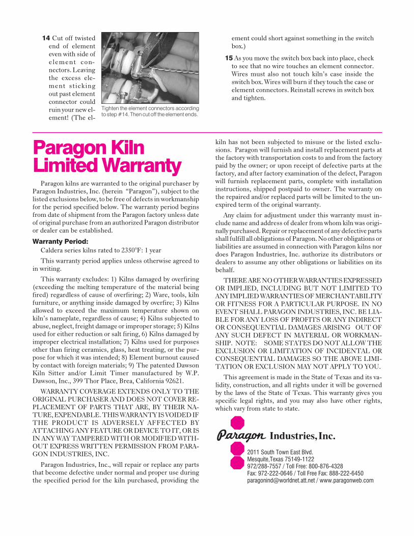
14 Cut off twistedend of elementeven with side ofelement con-nectors. Leavingthe excess ele-ment stickingout past elementconnector couldruin your new el-ement! (The el-
ement could short against something in the switchbox.)
15 As you move the switch box back into place, checkto see that no wire touches an element connector.Wires must also not touch kiln’s case inside theswitch box. Wires will burn if they touch the case orelement connectors. Reinstall screws in switch boxand tighten.
Paragon KilnLimited Warranty
Paragon kilns are warranted to the original purchaser byParagon Industries, Inc. (herein “Paragon”), subject to thelisted exclusions below, to be free of defects in workmanshipfor the period specified below. The warranty period beginsfrom date of shipment from the Paragon factory unless dateof original purchase from an authorized Paragon distributoror dealer can be established.
Warranty Period:Caldera series kilns rated to 2350°F: 1 year
This warranty period applies unless otherwise agreed toin writing.
This warranty excludes: 1) Kilns damaged by overfiring(exceeding the melting temperature of the material beingfired) regardless of cause of overfiring; 2) Ware, tools, kilnfurniture, or anything inside damaged by overfire; 3) Kilnsallowed to exceed the maximum temperature shown onkiln’s nameplate, regardless of cause; 4) Kilns subjected toabuse, neglect, freight damage or improper storage; 5) Kilnsused for either reduction or salt firing, 6) Kilns damaged byimproper electrical installation; 7) Kilns used for purposesother than firing ceramics, glass, heat treating, or the pur-pose for which it was intended; 8) Element burnout causedby contact with foreign materials; 9) The patented DawsonKiln Sitter and/or Limit Timer manufactured by W.P.Dawson, Inc., 399 Thor Place, Brea, California 92621.
WARRANTY COVERAGE EXTENDS ONLY TO THEORIGINAL PURCHASER AND DOES NOT COVER RE-PLACEMENT OF PARTS THAT ARE, BY THEIR NA-TURE, EXPENDABLE. THIS WARRANTY IS VOIDED IFTHE PRODUCT IS ADVERSELY AFFECTED BYATTACHING ANY FEATURE OR DEVICE TO IT, OR ISIN ANY WAY TAMPERED WITH OR MODIFIED WITH-OUT EXPRESS WRITTEN PERMISSION FROM PARA-GON INDUSTRIES, INC.
Paragon Industries, Inc., will repair or replace any partsthat become defective under normal and proper use duringthe specified period for the kiln purchased, providing the
kiln has not been subjected to misuse or the listed exclu-sions. Paragon will furnish and install replacement parts atthe factory with transportation costs to and from the factorypaid by the owner; or upon receipt of defective parts at thefactory, and after factory examination of the defect, Paragonwill furnish replacement parts, complete with installationinstructions, shipped postpaid to owner. The warranty onthe repaired and/or replaced parts will be limited to the un-expired term of the original warranty.
Any claim for adjustment under this warranty must in-clude name and address of dealer from whom kiln was origi-nally purchased. Repair or replacement of any defective partsshall fulfill all obligations of Paragon. No other obligations orliabilities are assumed in connection with Paragon kilns nordoes Paragon Industries, Inc. authorize its distributors ordealers to assume any other obligations or liabilities on itsbehalf.
THERE ARE NO OTHER WARRANTIES EXPRESSEDOR IMPLIED, INCLUDING BUT NOT LIMITED TOANY IMPLIED WARRANTIES OF MERCHANTABILITYOR FITNESS FOR A PARTICULAR PURPOSE. IN NOEVENT SHALL PARAGON INDUSTRIES, INC. BE LIA-BLE FOR ANY LOSS OF PROFITS OR ANY INDIRECTOR CONSEQUENTIAL DAMAGES ARISING OUT OFANY SUCH DEFECT IN MATERIAL OR WORKMAN-SHIP. NOTE: SOME STATES DO NOT ALLOW THEEXCLUSION OR LIMITATION OF INCIDENTAL ORCONSEQUENTIAL DAMAGES SO THE ABOVE LIMI-TATION OR EXCLUSION MAY NOT APPLY TO YOU.
This agreement is made in the State of Texas and its va-lidity, construction, and all rights under it will be governedby the laws of the State of Texas. This warranty gives youspecific legal rights, and you may also have other rights,which vary from state to state.
2011 South Town East Blvd.Mesquite,Texas 75149-1122972/288-7557 / Toll Free: 800-876-4328Fax: 972-222-0646 / Toll Free Fax: [email protected] / www.paragonweb.com
Tighten the element connectors accordingto step #14. Then cut off the element ends.