
Parabolic Trough-Solar Tracking and Energy Extraction
32
Parabolic Trough-Solar Tracking and Energy Extraction By Saad Almonnieay, Robert Blaskey, Daniel Chief, Christopher Mesko, Jairo Rivera, and Jacob Seitzer Team 14 Final Report Document Submitted towards partial fulfillment of the requirements for Mechanical Engineering Design II – Spring 2015 Department of Mechanical Engineering Northern Arizona University Flagstaff, AZ 86011
Transcript of Parabolic Trough-Solar Tracking and Energy Extraction
Parabolic Trough-Solar
Tracking and Energy Extraction
By
Saad Almonnieay, Robert Blaskey, Daniel Chief, Christopher
Mesko, Jairo Rivera, and Jacob Seitzer
Team 14
Final Report
Document
Submitted towards partial fulfillment of the requirements for
Mechanical Engineering Design II – Spring 2015
Department of Mechanical Engineering
Northern Arizona University
Flagstaff, AZ 86011

Table of Contents
Introduction………………………………………………………………………….…….1
Project Definition……………………………………………………………….....1
Trough Initial Condition……………………………………………………….….1
Tire Information……………………………………………………………………….…..2
Chain Information………………………………………………………………………....4
Gear Box…………………………………………………………………………………..5
Edge Trimming…………………………………………………………………………..10
Material to Cover Damaged Surface……………………………………………………..14
Tracking components……………....………………………………………………….....15
Motor and Drive………………………………………………………………….16
Programing……………………………………………………………………….18
Control Box ……………………………………………………………………...19
Energy Extraction.……………………………………………………………………….21
Design……………………………………………………………………………22
Piping….………………………………………………………………………....22
Energy Storage…………………………………………………………….……..23
Final Solar Energy System……………………………………………………………….24
Solar Energy Results……………………………………………………………………..25
Total Cost………………………………………………………………………………...28
Conclusion……………………………………………………………………………….29
References……………………………………………………………………………….30

1
Introduction (Christopher)
Northern Arizona University was gifted a parabolic trough 15 years ago. It had not been
operated since arrival likely due to a missing energy extraction system. After years of no
maintenance or operation, damages accumulated on the trough and its components. Currently,
the trough is located in the solar shack, a fenced area. The frame is rusted with the least amount
of damage; however components of the trough such as the surface, wheels, motor, and control
box all are too severely damaged to use. Many other minor damages are to be overcome as well
as designing a useful method to using the solar energy collected by the trough.
Project Definition (Christopher)
The purpose of this project is to repair and replace the inoperable tracking system, and to
design and install an energy extraction system. Our client, Dr. Kosaraju, has needs for us given
as the following: Assemble an operable tracking system and install an energy extraction system.
Team goals for the tracking system are for it to be controlled via a computer to follow the sun
throughout the day and reset the trough to a downward position when the day is over. Another
team goal with regards to the energy extraction system is to be capable of heating water to a
change of 40 degree Fahrenheit at different times of the day. Repairing the surface, adding trim
to the edges to enclose the trough, adding an enclosure to cover the motor, programming
operable tracking controls, and other tasks were needed to repair damage to the trough, as well as
to prevent future harm.
Trough Initial Condition (Daniel)
In this section the team will discuss the initial conditions of the parabolic trough. The first
topic covered is the condition of the tires. The pre-existing tires on the trough were flat and
weather damaged. The team tried to restore the tires and inflate all four tires. Cracks from years
of sun and weather damage prevented the air to stay in the tire. The next topic is the chain. On
further inspection we did not find a chain on the gears located on the trough. Due to a
nonexistent chain, the parabolic trough could move about freely. The gearbox, with years
without operation, has not been maintained. Over 15 years of sitting, the oil has drained from the
upper level of the gearbox and into the lower level. The oil left in the lower gearbox was black
and gritty. The gasket keeping the oil from leaking has failed. Most of the oil dripped down the
2
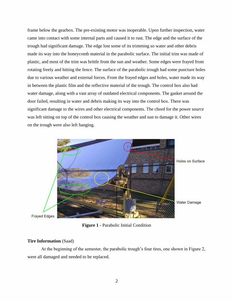
frame below the gearbox. The pre-existing motor was inoperable. Upon further inspection, water
came into contact with some internal parts and caused it to rust. The edge and the surface of the
trough had significant damage. The edge lost some of its trimming so water and other debris
made its way into the honeycomb material in the parabolic surface. The initial trim was made of
plastic, and most of the trim was brittle from the sun and weather. Some edges were frayed from
rotating freely and hitting the fence. The surface of the parabolic trough had some puncture holes
due to various weather and external forces. From the frayed edges and holes, water made its way
in between the plastic film and the reflective material of the trough. The control box also had
water damage, along with a vast array of outdated electrical components. The gasket around the
door failed, resulting in water and debris making its way into the control box. There was
significant damage to the wires and other electrical components. The chord for the power source
was left sitting on top of the control box causing the weather and sun to damage it. Other wires
on the trough were also left hanging.
Figure 1 - Parabolic Initial Condition
Tire Information (Saad)
At the beginning of the semester, the parabolic trough’s four tires, one shown in Figure 2,
were all damaged and needed to be replaced.

3
Figure 2 - Damaged tires
The tires were replaced with Marathon 4.10/3.50-4 tires, which cost $14.50 per tire plus
shipping. After the tires were purchased, the team started the process of installing the new tires
on the trough.
During installation of the new tires, one of the four casters broke, which then generated
three solutions to this problem. The first option was to replace all the casters with new casters
that are only sold with tires and not separately. The total cost was $65.99 for each combination
of caster and tire with a subtotal of $263.96 if the Marathon tires were returned. The second
option was to weld the broken caster using the NAU machine shop. Although this option would
have no cost, the durability of the caster would be unknown and may fail again with the load of
the parabolic trough. The third option was to replace only one caster that would come in

4
combination with a new tire and keep one of the purchased Marathon tires as a spare at a cost of
$65.99. One caster and tire combination was purchased as it was the best solution at a reasonable
cost. The purchased caster and tire combination is displayed in Figure 3.
Figure 3 - Replaced Caster with the tire
Chain information (Saad)
When researching chains, the specifications needed were the length, pitch, and roller
width. We measured the length using a tape measure around the large sprocket, seen in Figure 4,
and small sprocket (not pictured). The measured distance found was 75 inches or 6.25 ft. From
McMaster-Carr, the chain lengths are rounded up to the nearest foot. Therefore, the chain length
required was 7 feet. Also measured was the pitch and roller width needed. The values measured
are ⅝ in pitch and ⅜ in roller width. With these values, an ideal chain was found on McMaster-
Carr’s website. The chain purchased is a standard steel ANSI 50 roller chain and links, with a

5
pitch of ⅝ in and roller width of ⅜ in. This chain has a working load limit at 561 lbs. and costs
$5.98 per foot that had a total of $41.86 before shipping.
Figure 4 - Big Sprocket with missing chain
Gearbox (Saad)
One of the tasks to complete was to check the interior of the gearbox and determine the
condition of the parts by removing the rust and oil from the assembly. The process was started by
disassembling the gearbox, which contains an upper level gearbox and lower level gearbox. The
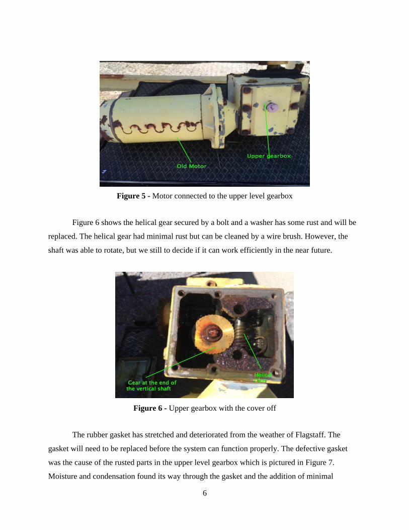
upper level gearbox is connected to the motor which can be seen in Figure 5. The motor shaft
and the worm gear are secured together by a rectangular key. After disassembling the cover plate
lubricating oil was found that turned from a golden color to black. Since the system had not been
operated or maintained for over 15 years, there was minimal amount of oil left in the upper level
gearbox. Most of the lubricating oil drained down to the lower level of the gearbox. The interior
surface and the worm gear holding the horizontal shaft showed some rust.
6
Figure 5 - Motor connected to the upper level gearbox
Figure 6 shows the helical gear secured by a bolt and a washer has some rust and will be
replaced. The helical gear had minimal rust but can be cleaned by a wire brush. However, the
shaft was able to rotate, but we still to decide if it can work efficiently in the near future.
Figure 6 - Upper gearbox with the cover off
The rubber gasket has stretched and deteriorated from the weather of Flagstaff. The
gasket will need to be replaced before the system can function properly. The defective gasket
was the cause of the rusted parts in the upper level gearbox which is pictured in Figure 7.
Moisture and condensation found its way through the gasket and the addition of minimal

7
lubrication oil, resulted in rust. All hardware has also been replaced. The drain plug located on
the upper level gearbox is in working condition.
Figure 7: Upper gearbox cover
After disassembling the side cover mounted to the gearbox to observe the interior of it, it
was found that it contains a vertical worm gear connected to the vertical shaft that rotates a
helical gear in the same shaft located at the upper gearbox. The worm gear is connected
perpendicularly to another helical gear located in the horizontal shaft that rotates the outer small
sprocket. The vertical gear coming down has a roller ball bearing attached to it. As seen in
Figure 8. The bearing sits between the upper level gearbox and the lower level gearbox to reduce
friction and secure the vertical shaft. The roller ball bearing and the vertical shaft are in good
condition. This is due to the lubricating oil protecting the parts from condensation and moisture.

8
Figure 8 -Vertical worm gear connecting the upper level to the lower level gearbox
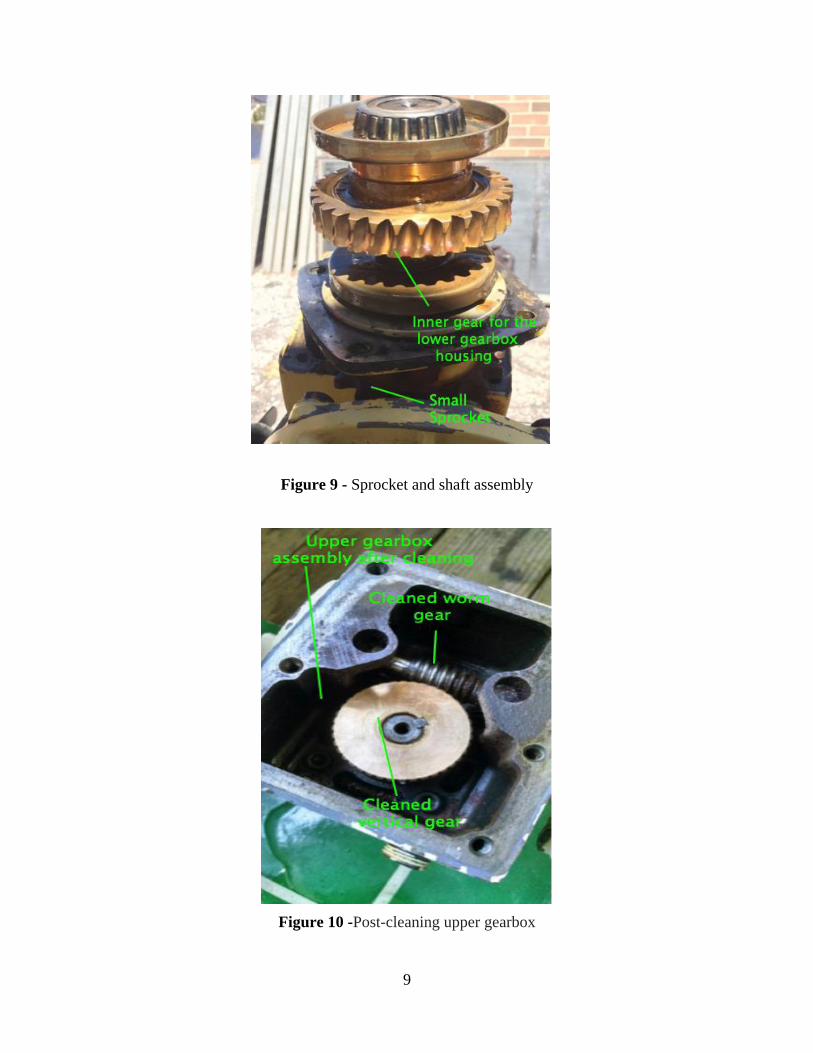
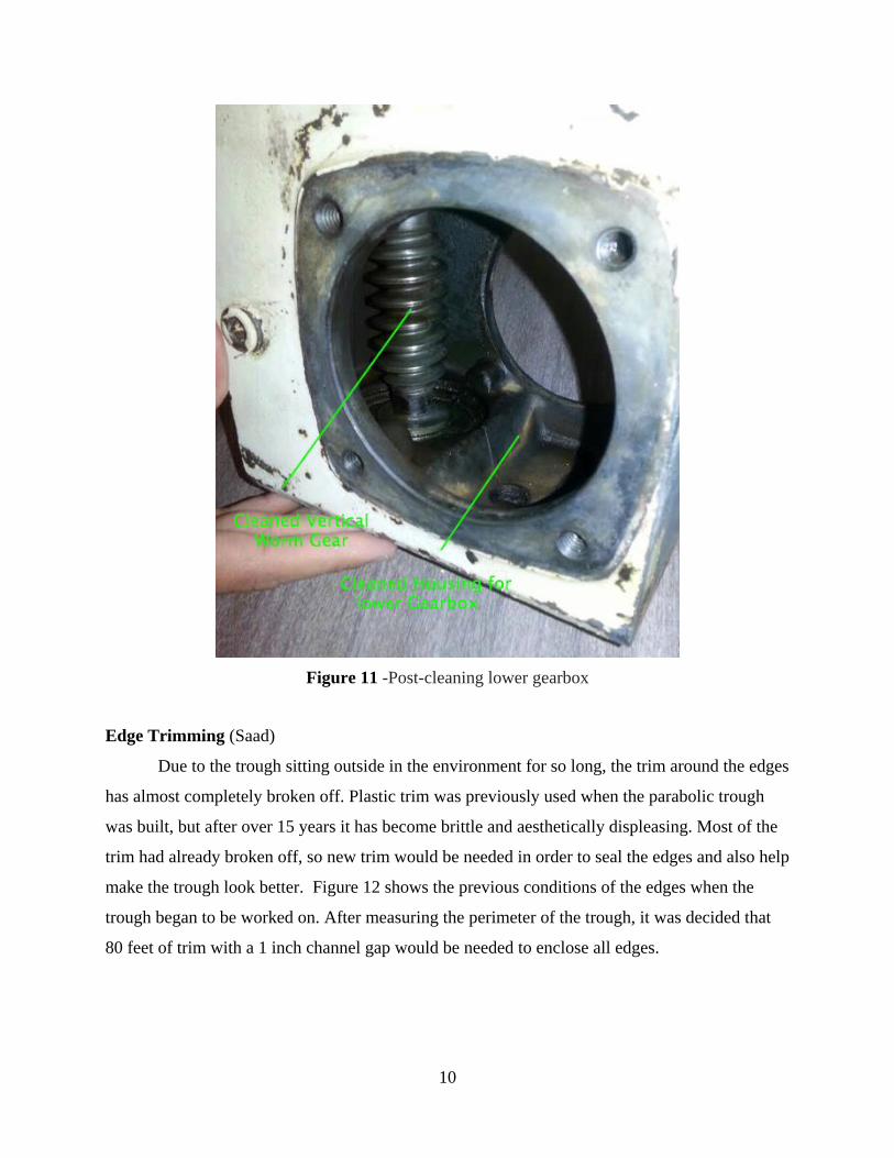
The gearbox was taken to Coconino Auto Suppliers to get it professionally cleaned. The
total cost for the cleaning was $35, and the material for a new gasket is also sold there for $8 a
sheet. The upper and lower gearbox was cleaned up well with the exception of a small bit of rust
on the worm gear located in the upper gearbox. Figures 9, 10 and 11 show the gearbox after it
was professionally cleaned. The gearbox will be used for the tracking system of the parabolic
trough.
9
Figure 9 - Sprocket and shaft assembly
Figure 10 -Post-cleaning upper gearbox
10
Figure 11 -Post-cleaning lower gearbox
Edge Trimming (Saad)
Due to the trough sitting outside in the environment for so long, the trim around the edges
has almost completely broken off. Plastic trim was previously used when the parabolic trough
was built, but after over 15 years it has become brittle and aesthetically displeasing. Most of the
trim had already broken off, so new trim would be needed in order to seal the edges and also help
make the trough look better. Figure 12 shows the previous conditions of the edges when the
trough began to be worked on. After measuring the perimeter of the trough, it was decided that
80 feet of trim with a 1 inch channel gap would be needed to enclose all edges.

11
Figure 12 - Initial condition of edges
In order to determine what kind of trim to use, a material that has a long lifespan was
desired. Although plastic was previously used, metal became the new material of choice because
of the longer lifespan it has over plastic, it was found to be less expensive, and it could also hold
down the areas of the edge that were bent, shown in Figure 13. Aluminum specifically was
chosen because it is cheap and easy to work with. From Metals Depot, 8 ft. sections of 1 ¼”
length legs, 1 ¼” base width, and ⅛” thickness, giving us the 1” gap needed, were found and
were ready to be shipped. Once the material was chosen, ten 8ft sections were ordered to ensure

12
that we would have enough material in case anything during installation went wrong. The total
cost of the aluminum trim was $220.38.
Figure 13 - Bent corner of trough
For the curved edges, a way to install the trim had to be decided since bending the 8ft
lengths of aluminum was not possible given the resources available. In order to overcome this, 2
inch sections were cut and installed individually in order to ensure that there would be no gaps in
the trim due to the curve. Figure 14 shows how these small segments look on the trough,
showing that there are no gaps.
Figure 14- Installed trim on flat and curved edge

13
Another concern about the installation of the aluminum trim was that there is a small gap
in the center of the trough perpendicular to its axis of rotation, (0.5” on one side, 2” on the other)
which does not allow room for sliding the trim on. To overcome this, there were several options
to choose from. One way to apply the trim would be to cut the aluminum in half along its length,
then apply each half to each side of the trough, and seal the cut with the adhesive. Another option
would be to just lay a material across the gap, such as Mylar, and leave the edge open, but it will
still be protected from rain and snow since the trough will always be in its upright position. The
only problem with this is that because Mylar is so thin, a puncture in the material would be easy
due to the size of the gap. Placing a stronger material underneath for support would solve this
problem, but application may be inefficient and alter the reflective surface towards the parabola’s
focal point. The third option is to remove one or two of the supports in order to slightly bend the
trough and slide the aluminum onto the edge. Because the materials of the trough are already
flexible, this option could be simple if the supports are easy to remove, but could be very
difficult due to the condition of the corrosion wearing down the supports and possibly losing the
supports entirely. Our team chose the third option in order to install the trim along the inner sides
of the trough as well as shorten the legs of the aluminum trim. Figure 15 shows the trim on the
inner side of the curved edge installed.
Figure 15- Inner trim installed
14
While installing, adhesive has also been used to help seal the edges. A construction
grade, weather resistant multi-surface adhesive was chosen due to the harsh conditions the trough
may experience. This was found at Home Depot for only $2.40 a bottle, with a total cost of $7.20
for three bottles needed.
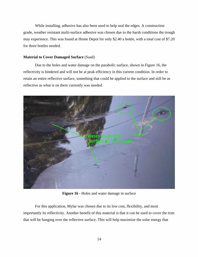
Material to Cover Damaged Surface (Saad)
Due to the holes and water damage on the parabolic surface, shown in Figure 16, the
reflectivity is hindered and will not be at peak efficiency in this current condition. In order to
retain an entire reflective surface, something that could be applied to the surface and still be as
reflective as what is on there currently was needed.
Figure 16 - Holes and water damage in surface
For this application, Mylar was chosen due to its low cost, flexibility, and most
importantly its reflectivity. Another benefit of this material is that it can be used to cover the trim
that will be hanging over the reflective surface. This will help maximize the solar energy that

15
will be absorbed. Using Amazon.com, a 100 ft² (4 feet wide, 25 feet long) roll was found for
$20.00.
After we successfully finished installing the trim to the edges of the trough, we started to
apply Mylar to the surfaces to cover the holes in the surface. We finished applying Mylar to the
damaged surface, so the trough will once again be able to rest in its upright position and the
complete surface can be reflective. Figure 17 shows the application of the Mylar on the reflective
surface.
Figure 17- Mylar applied to parabolic surface
Tracking Components (Jacob)
The most important milestone in the project so far has been to successfully install and
operate the components needed to rotate the trough. This has been difficult due to the previous
conditions of the trough as well as the lack of documentation for the previous components.
Because of this, and through discussions and professional help, the team ordered a 1hp AC
motor. The drive selected was an AC drive from AutomationDirect, and a programmable PLC
with a power inverter, also from AutomationDirect. A control box will also be purchased to
ensure the electrical components will be protected from various weather conditions.

16
Motor and Drive (Jacob)
The motor selected was a Marathon 1HP, 230V, three-phase AC motor. This will
supply the power and torque to turn the trough smoothly and efficiently. The next step to power
the motor was to connect it to the drive. From AutomationDirect, a GS2-21P0 230V drive was
ordered. This, however, posed a problem for the team. Upon inspection of the solar shack, the
230V three-phase power supply needed could not be obtained without extra costs and time. To
avoid this, a new drive was ordered. A GS2-11P0 drive was ordered, which has the same output
needed to run the motor, but the input power is 120V single-phase, which is readily available in
the solar shack.
Once the new drive arrived, the team went straight to connecting the two and testing
motor function. The drive needed to be programmed to meet the specifications of the motor,
which was a simple process and connections were made quickly. Shown in Figure 18 is the
motor and drive wired together.
Figure 18 - Motor and drive connected
17
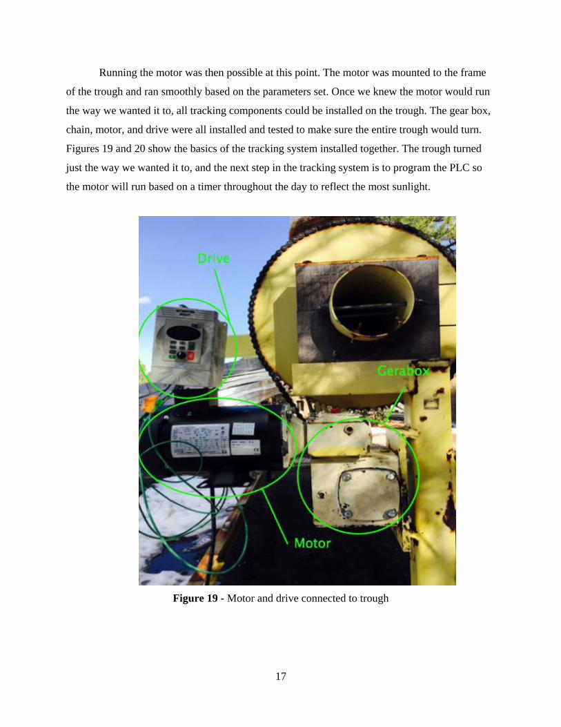
Running the motor was then possible at this point. The motor was mounted to the frame
of the trough and ran smoothly based on the parameters set. Once we knew the motor would run
the way we wanted it to, all tracking components could be installed on the trough. The gear box,
chain, motor, and drive were all installed and tested to make sure the entire trough would turn.
Figures 19 and 20 show the basics of the tracking system installed together. The trough turned
just the way we wanted it to, and the next step in the tracking system is to program the PLC so
the motor will run based on a timer throughout the day to reflect the most sunlight.
Figure 19 - Motor and drive connected to trough

18
Figure 20 - Chain connected to gearbox and turning gear
Wires and electrical components will not be exposed to the environment, but rather enclosed,
protected from the weather using a control box.
Programming (Jacob)
Using a Basic CLICK PLC from AutomationDirect, the team will be able to control the
drive and motor automatically to ensure the largest amount of sunlight is reflected towards the
energy extraction system. The software included with the PLC is not something we have much
experience with, so creating a program with the proper functions proved to be difficult.
AutomationDirect has many helpful resources for their programming software, so learning the
basics of the software made creating a complicated program easier.
The software uses Relay Ladder Logic programming, so a series of on/off switches along
with series of timers will control the drive to move during specified time intervals. Once the PLC
is turned on, the trough will rotate to its starting position (upside down), and once sunrise begins
the trough will rotate to its initial tracking position at 61° from the horizon. Throughout the day,
19
the trough will rotate in small increments every five minutes in order to keep the sun’s reflection
at the focal point. After 159 rotations, the sun will have set and the trough will revert back to its
initial tracking position and wait ten hours and forty-five minutes until sunrise begins again.
These values are only for spring months, and will change accordingly for summer, fall, and
winter. Specifications on sunrise/sunset times as well as the elevation angle of the sun during the
other seasons will need to be determined when the time comes.
With the CLICK PLC, the possibilities of various control programs/parameters are
endless. Various inputs/outputs can be connected to the PLC, as well as extra relays, such as a
thermocouple relay to internally measure the temperature of the water so the system can shut off
automatically once it reaches a specified temperature.
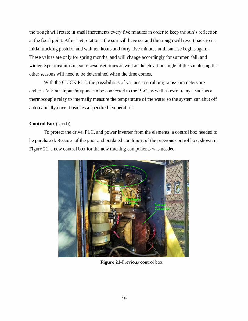
Control Box (Jacob)
To protect the drive, PLC, and power inverter from the elements, a control box needed to
be purchased. Because of the poor and outdated conditions of the previous control box, shown in
Figure 21, a new control box for the new tracking components was needed.
Figure 21-Previous control box

20
Shown in Figure 22 is a schematic of each component and clearances required for each to
determine the dimensions of the control box needed.
Figure 22 - Schematics of control box
Based on these dimensions, a 20” X 12” X 8” will suit the need for all components
necessary to run the tracking system. Shown in Figure 23, the mounted control box along with
the installed components is shown.
Figure 23 - Control box and components
21
Above the PLC and inverter there is room for extra components if desired for future uses.
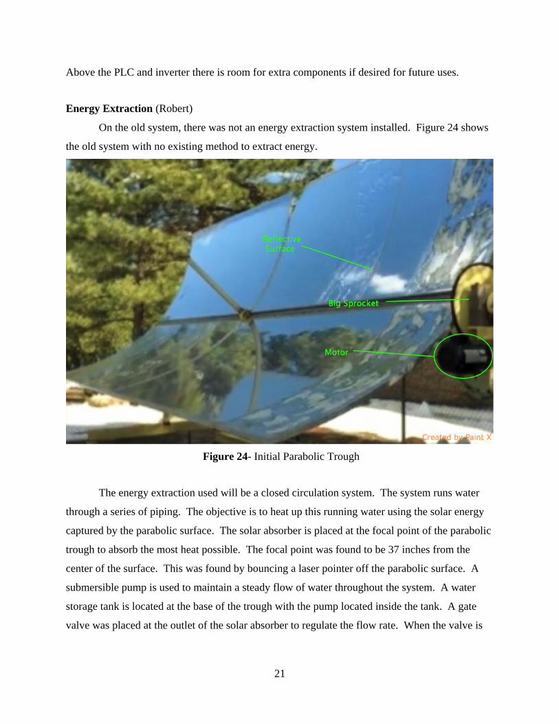
Energy Extraction (Robert)
On the old system, there was not an energy extraction system installed. Figure 24 shows
the old system with no existing method to extract energy.
Figure 24- Initial Parabolic Trough
The energy extraction used will be a closed circulation system. The system runs water
through a series of piping. The objective is to heat up this running water using the solar energy
captured by the parabolic surface. The solar absorber is placed at the focal point of the parabolic
trough to absorb the most heat possible. The focal point was found to be 37 inches from the
center of the surface. This was found by bouncing a laser pointer off the parabolic surface. A
submersible pump is used to maintain a steady flow of water throughout the system. A water
storage tank is located at the base of the trough with the pump located inside the tank. A gate
valve was placed at the outlet of the solar absorber to regulate the flow rate. When the valve is

22
open, water flows into the pump, circulating through the system. A piping thermocouple is at the
inlet of the solar absorber to measure the temperature of the water
Design (Robert)
Figure 25 below shows the schematic for the energy extraction system. The placement of
the solar storage is mounted on the frame underneath the entire trough. The tank is 15 inches in
height with a clearance of two inches from the ground. The outlet piping is inside the hollow
steel section that is the length of the trough. Flexible hoses are attached to each end of the pipes
in order to accommodate for when the parabolic trough rotates. The solar absorber is mounted
on each side of the trough and at an existing hollow steel section located in the middle of the
surface. The adjustable gate valve and K-type thermocouple are attached at the 90 degree
elbows of the solar absorber.
Figure 25- Extraction Design
Piping (Robert)
Most of the materials of the extraction system were found at a local hardware store.
EMT steel is used for the piping, and the solar absorber is painted black. Temperature resistant
flexible hoses were installed. At the 90 degree angles in the schematic, a temperature resistant
flexible hose maximizes the efficiency of the flow rate. The solar absorber was installed with

23
mounting brackets. While attaching elbows to each end of the solar absorber, a K-type
thermocouple and adjustable gate valve were attached to the inlet and outlet ends, respectively.
The K-type thermocouple is used to monitor the temperature in order to get maximum efficiency
and the valve is to control the flow rate throughout the system. Drills were available to members
of the team in order to drill all the holes necessary for mounting.
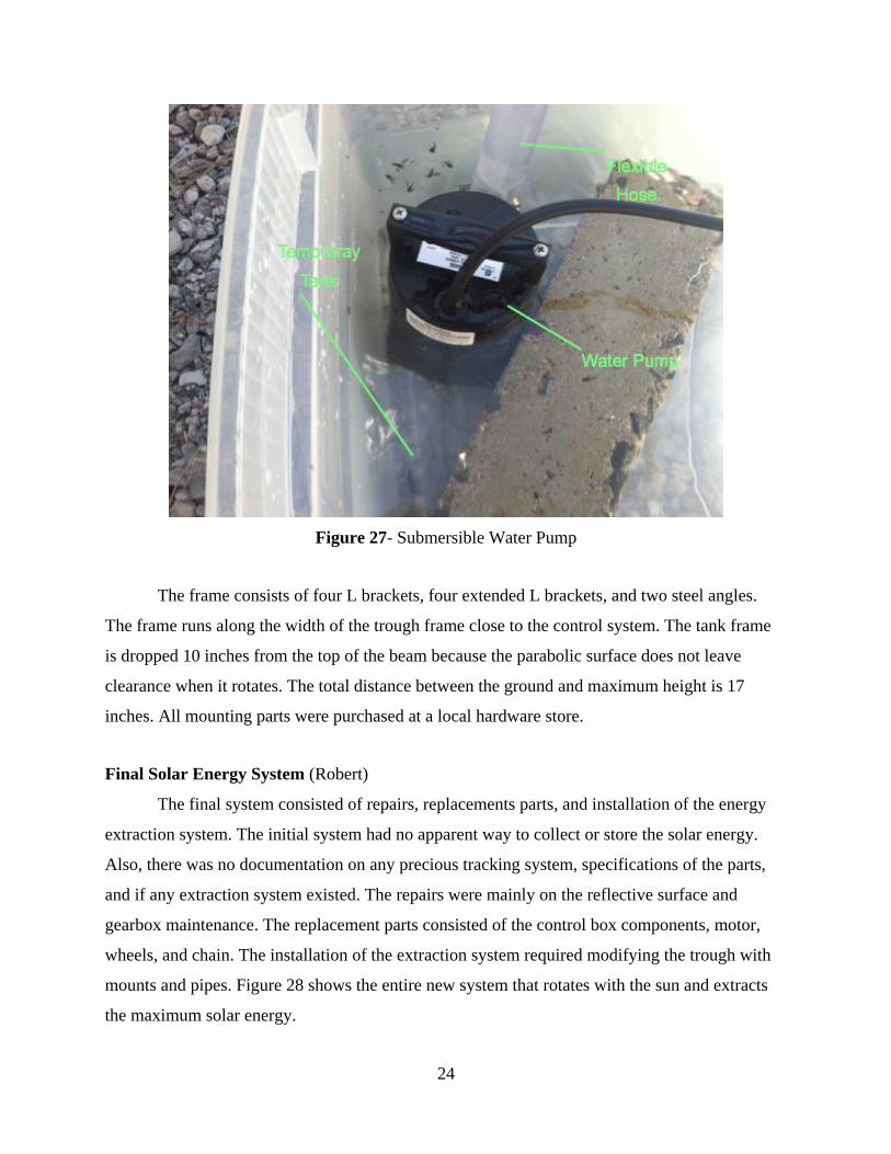
Energy Storage (Robert)
There are three main components for the process of energy storage: the submersible
pump, the water tank, and the frame that the water tank rests on. The water pump was purchased
at a local hardware store that runs at a maximum of 750 gallons per hour (GPH) that submerges
into the water tank. It is a Little Giant water pump with one inch diameter output and ⅙ HP
power. The water tank is a 55 gallon rectangular tank from the Plastic Water Tanks Company.
The specifications are 42”x26”x16” with an eight inch fitting on the top with a drain on the short
side of the tank. The eight inch fitting made it possible to insert a five inch diameter pump and
two one inch diameter hoses. Figure 26 displays the 55 gallon water tank and Figure 27 shows
the submersible water pump used in the system.
Figure 26- 55 Gallon Water Tank (Plasticwatertanks.com)
24
Figure 27- Submersible Water Pump
The frame consists of four L brackets, four extended L brackets, and two steel angles.
The frame runs along the width of the trough frame close to the control system. The tank frame
is dropped 10 inches from the top of the beam because the parabolic surface does not leave
clearance when it rotates. The total distance between the ground and maximum height is 17
inches. All mounting parts were purchased at a local hardware store.
Final Solar Energy System (Robert)
The final system consisted of repairs, replacements parts, and installation of the energy
extraction system. The initial system had no apparent way to collect or store the solar energy.
Also, there was no documentation on any precious tracking system, specifications of the parts,
and if any extraction system existed. The repairs were mainly on the reflective surface and
gearbox maintenance. The replacement parts consisted of the control box components, motor,
wheels, and chain. The installation of the extraction system required modifying the trough with
mounts and pipes. Figure 28 shows the entire new system that rotates with the sun and extracts
the maximum solar energy.

25
Figure 28- Final Solar Energy System
Solar Energy Results (Jairo)
In the solar energy extraction, the black solar absorber pipe is heated through radiation
reflected from the panels and conducted through the absorber pipe and finally heat transfer
through convection to the water flowing through the pipe as shown in Figure 29. Within 10
minutes of the trough tracking the sun, the absorber reached a temperature of 350° Fahrenheit.
Our team conducted two different tests for our system for 15 gallons of water, which consisted of
a constant flow rate at different times of a clear, sunny sky day with a high of 63° Fahrenheit,
and a constant change of temperature at different flow rates was also tested.

26
Figure 29- Heat transfer of system
A plot of the temperature change at 750 Gallons per Hour flow rate at three different
times of the day for 60 minutes is shown in Figure 30.
Figure 30- Time vs. Temperature

27
The plot indicates that at different times of the day, the water flowing through the pipe
will have a different change of temperature for 60 minutes. At 9:30 am the initial temperature of
the water was 57.2° Fahrenheit and the final temperature after 60 minutes was 80.6° F for a total
change of temperature of 23.4° F. At 12:00pm the initial temperature of the water was 72.1° F
and final temperature after 60 minutes was 107.2° F for a total change of temperature of 35.1° F.
At 1:30pm the initial temperature of the water was 78.8° F and final temperature after 60 minutes
was 118.4° F for a total change of temperature of 39.6° F. The results show that the temperature
at which the water can be increased by varies throughout the day, but the system does increase
the temperature at roughly the same rate for the times tested.
A constant change of 40° Fahrenheit for different flow rates of water through the
absorber is plotted in Figure 31 and the values for each flow rate with their respective times to
achieve the desired change of temperature can be seen in Table 1.
Figure 31: Flow rate vs. Time
Table 1: Flow rate, Temperature Range, and Time
28
As the flow rate decreases, the time to achieve a 40° Fahrenheit change in temperature
increases. Since the water is recirculated in our system, the time to change the water temperature
is lower in higher flow rates due to the water being heated through convection inside the pipe,
but then being added back into the tank that contains water at a lower temperature. The faster the
flow rate is able to recirculate the entire water in the tank through the system, the temperature of
the water tank changes at a higher rate. The gallons per hour versus the time it takes to change
the water temperature by 40° Fahrenheit is a decreasing 2nd degree polynomial function.
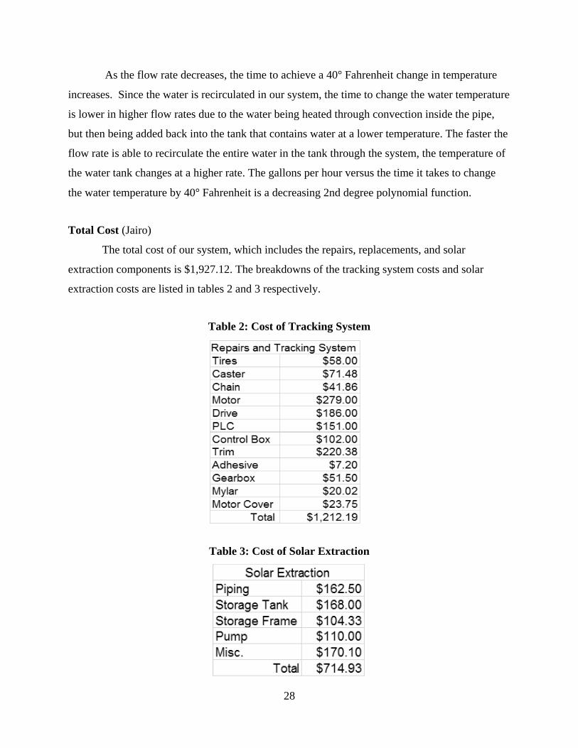
Total Cost (Jairo)
The total cost of our system, which includes the repairs, replacements, and solar
extraction components is $1,927.12. The breakdowns of the tracking system costs and solar
extraction costs are listed in tables 2 and 3 respectively.
Table 2: Cost of Tracking System
Table 3: Cost of Solar Extraction

29
Overall, the tracking system cost more than the solar extraction system by $497.26, but
without the tracking system, the solar extraction system would not be as efficient as it can be.
Conclusion (Jairo)
The tracking system is now operable. The motor, chain, and tires have been replaced, and
the gearbox has been restored. Aluminum trimming has been added to secure the edges of the
trough, as well as Mylar added to cover the damaged panels. The energy extraction system has
been installed to make use of the energy provided by the sun. At the maximum flow rate of 750
GPH, the amount of time to achieve a 40° Fahrenheit change is 43 minutes. When flowing at 100
GPH, one hour is needed to achieve a change of 40° Fahrenheit. With an operable tracking
system and energy extraction system, the parabolic trough is ready to demonstrate how solar
energy can be reflected onto a fixed pipe to heat a liquid. If continuing on with this project,
programming the tracking system to complete specific tasks would be the main focus.
Gantt Chart
The Gantt chart shows the timeline of the tasks of the project. Although the project is in
its late stages, a general timeline has been made for the total projected outcome. The generated
Gantt chart for Team 14 may be seen in figure 31. This Gantt chart shows the process that was
done last semester.
Figure 31- Gantt chart

30
References
Marathon 20011 4.10/3.50-4 Sawtooth Tread Pneumatic, 2.25" Offset, 3/4" Bearings." Global
Industrial. N.p., n.d. Web. 15 Oct. 2014.
McMaster-Carr. McMaster-Carr. N.p., n.d. Web. 15 Oct. 2014.
Budynas, Richard G., J. Keith. Nisbett, and Joseph Edward. Shigley. Shigley's Mechanical
Engineering Design. New York: McGraw-Hill, 2011. Print.
Plasticwatertanks.com, N.P, n.d. Web. 7 April 2015.
http://www.plasticwatertanks.com/p/cn7xk/trans55-55-gallon-portable-flat-bottom-tank
Bergman, Theodore L., Adrienne S. Lavine, Frank P. Incropera, David P. Dewitt. Fundamentals
of Heat and Mass Transfer. 7th ed. New York: Wiley, 2011. Print.
Munson, Bruce R., Alric P. Rothmayer, Theodore H. Okiishi, Wade W. Huebsch. Fundamentals
of Fluid Mechanics. 7th ed. New York: Wiley, 2012. Print.
AutomationDirect.com, Web. 20 Jan 2015.
http://www.automationdirect.com/adc/Shopping/Catalog/Motors/AC_Motors_-
_General_Purpose_and_Inverter_Duty_(0.25_-_300HP)/AC_Motors_-
_Inverter_Duty,_Marathon_(0.25_-_100HP)/Marathon_MicroMAX_(0.25HP_to_10HP)/Y364