
Paper Title (use style: paper title) · Web viewThe packet header fields in the flow table lookups...
14
“© 2014 IEEE. Personal use of this material is permitted. Permission from IEEE must be obtained for all other uses, in any current or future media, including reprinting/republishing this material for advertising or promotional purposes, creating new collective works, for resale or redistribution to servers or lists, or reuse of any copyrighted component of this work in other works.”
Transcript of Paper Title (use style: paper title) · Web viewThe packet header fields in the flow table lookups...

“© 2014 IEEE. Personal use of this material is permitted. Permission from IEEE must be obtained for all other uses, in any current or future media, including reprinting/republishing this material for advertising or promotional purposes, creating new collective works, for resale or redistribution to servers or lists, or reuse of any copyrighted component of this work in other works.”

Analysing the performance of the OpenFlow standard for software-defined networking using the OMNeT++
network simulatorAmeen Banjar, Pakawat Pupatwibul, Robin Braun and Bruce Moulton
Centre for Real-Time Information Networks (CRIN) University of Technology, Sydney (UTS) Sydney,
Australia{11311103, 10926297}@uts.edu.au {robin.braun, bruce.moulton}@uts.edu.au
Abstract— Software-defined networking (SDN) is a relatively advanced method for implementing communication networks. SDN separates the decision maker, called the control plane, which decides where packets are sent, from the underlying infrastructure, called the data plane, which forwards packets to the decided destination. A newly emerging standard for SDN is the OpenFlow standard, which includes a standardized protocol for communications between the control plane and the data plane. This study analyses the extent to which the location of OpenFlow controllers affect the performance of an OpenFlow network. The analysis is undertaken using the OMNeT++ INET Framework discrete events network simulator. By analyzing key network metrics including round-trip-time (RTT) and data transfer rate (DTR), the results indicate the location of the controller has a demonstrable affect the performance of the network.
Keywords—Network Performance; Software- DefinedNetworks; OMNeT++.
I. INTRODUCTION
In the last few years network technologies have been improved significantly in performance, complexity, functionality and other aspects, because of current needs and necessities of the modern world. The Internet protocol suite, widely known as TCP/IP, is a networking model and the basic communication language or protocols used to connect hosts on the internet. TCP/IP is the best known protocol suits today because of the successful development of the internet, and thus useful to study the behaviours of this protocol further, by making use of simulations.
The new type of network that can be programmed by software applications based on network operating system as a controller for different needs and purposes. It facilitates the current network architecture and protocol designs.
The facilitation has been done by presented a new protocol called OpenFlow. OpenFlow is regarded as the first standardised communication interface that sits between the forwarding and controls layers of SDN architecture. SDN has developed the OpenFlow protocol as a key enabler, which provides flexible control of the forwarding plane of network devices as a message exchanger between an OpenFlow controller and OpenFlow switches [1]. Moreover, the
procedures for regulating data transmission between network elements of OpenFlow can also provide efficient level of performance, high consistency, more connectivity as well as rigorous standards of data protection.
For any new network protocol there are several approaches to test acceptability, performance and evaluation. One of the approaches is to perform a simulation, which has many advantages such as finding cost, flexibility, scalability, repeatability, and accessibility for many purposes, and the simulation is faster than real time in many cases. However, the simulation speed can be faster or slower than the real time. On the other hand, approaches which are running real devices, real operating systems and applications can deliver more realistic testing results, but it is costly to build a large experimental test-bed, and it is not easily accessible by industrial or academia unless they own it. As a result, using simulations are easier which they have no real operating systems and applications.
Network carriers attempted to cope with distributed environments by developing new technical solutions of routing protocols. However, there is only limited information on the performance of each, and realistic performance comparisons are not widely available. Until now, very few performance evaluations of OpenFlow architectures using OMNeT++ exist. Simulation tools can provide more suitable task of designing, building, and testing for users with practical feedback when developing real world systems. This will allow system designers to determine the correctness and efficiency of a design before the system is actually deployed. Another advantage of simulators is that they allow the evaluation among various network metrics and validation mechanisms to obtain results that are not experimentally measurable on larger geographically distributed architectures.
Our OMNeT++ simulation results are as accurate as those obtained from multiple running of the simulation to preserve accuracy of the simulation approach. This paper aims to evaluate simulations between OpenFlow and TCP/IP module, and to analyse the effect of different networks on a variety of performance metrics, for example Data Transmission Rate (DTR) and the mean round-trip-time (RTT) for the nodes in the investigated networks.

The remainder of this paper is organized as follows. Section II presents the basic of communication networks, and INET simulation package in OMNeT++. In Section III, related works on network simulation and emulation tools are explained. Section IV describes a simple communication scenario in OpenFlow networks, and provides an overview of the performance metrics. In Section V, the measurement methodology is shown. The performance of different network architectures is also evaluated in this section. Finally, Section VI concludes the paper and provides direction for future works.
II. MOTIVATIONS
OMNeT++ can be applied to different network scenarios, topologies, behaviours and environments or other application fields for different purposes. Then, it can be studied and analysed to see how the system is functioning and performing. For example, applications of networking simulation area include network traffic, data transfer rate, packet counts and round trip time for packets transmission. OMNeT++ will be the first step for Australia when attempting to implement a new network infrastructure such as OpenFlow. OMNeT ++ is easy to simulate geographic distance and help predict how that would affect the behaviours of this new infrastructure, when considering different technologies or products running on different software. Thus, we have used OMNeT++ modules to design, simulate, verify, and analyse the performance of different networks protocols, where in this context we used TCP/IP and OpenFlow.
OpenFlow can offer network administrators the flexibility to manage, configure and optimise network resources, and thus can effectively control the network behaviour in real-time as well as deploying new network applications and services. OpenFlow-Based SDN can present several substantial benefits including centralised management and control of network devices from various vendors, the direct manipulation of new network services without having to configure each node individually, programmability by administrators, enterprises, users, and software vendor, and the ability to provide centralised and automated management which increases network security and reliability.
Currently, a related work of integrating the OpenFlow protocol version 1.2 in the INET framework for OMNeT++ has been developed. The motivation is to test the correctness of their implemented model in INET, and focus especially on the performance of controller’s placement based on a variety of performance metrics in the investigated network.
Different controller placements were evaluated for the Australian infrastructure topology. The results can be useful and highly beneficial for future production deployments of OpenFlow technology in Australia regarding which location is appropriate for the controller with the best and most efficient performance.
III. COMMUNICATION NETWORKS AND SIMULATIONFRAMEWORK
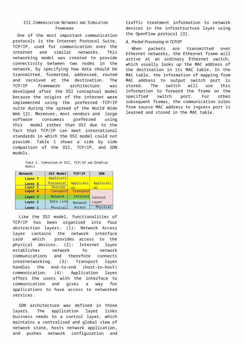
One of the most important communication protocols is the Internet Protocol Suite, TCP/IP, used for communication over the internet and similar networks. This networking model was created to provide connectivity between two nodes in the network, by specifying how data should be transmitted, formatted, addressed, routed and received at the destination. The TCP/IP framework architecture was developed after the OSI conceptual model because the origins of the internet were implemented using the preferred TCP/IP suite during the spread of the World Wide Web [2]. Moreover, most vendors and large software consumers preferred using this model rather than OSI due to the fact that TCP/IP can meet international standards in which the OSI model could not provide. Table 1 shows a side by side comparison of the OSI, TCP/IP, and SDN models.
TABLE I. COMPARISON OF OSI, TCP/IP AND OPENFLOW MODELS
Network Layers OSI Model TCP/IP SDNLayer 7 Application
Application ApplicationLayer 6 PresentationLayer 5 SessionLayer 4 Transport Transport
Control LayerLayer 3 Network InternetLayer 2 Data Link Network
AccessLayer 1 Physical Physical
Like the OSI model, functionalities of TCP/IP has been organised into four abstraction layers. (1): Network Access layer contains the network interface card which provides access to the physical devices. (2): Internet layer establishes network to network communications and therefore connects internetworking. (3): Transport layer handles the end-to-end (host-to-host) communication. (4): Application layer offers the users with the interface to communication and gives a way for applications to have access to networked services.
SDN architecture was defined in three layers. The application layer links business needs to a control layer, which maintains a centralised and global view of network state, hosts network application, and pushes network configuration and traffic treatment information to network devices in the infrastructure layer using the OpenFlow protocol [3].
A. Packet Processing in TCP/IPWhen packets are transmitted over Ethernet networks, the
Ethernet frame will arrive at an ordinary Ethernet switch, which usually looks up the MAC address of the destination in its MAC table. In the MAC table, the information of mapping from MAC address to output switch port is stored. The switch will use this information to forward the frame on the specified switch port. For other subsequent frames, the communication rules from source MAC address to ingress port is learned and stored in the MAC table.

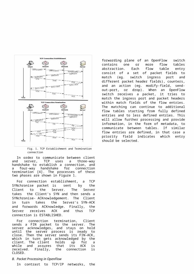
Fig. 1. TCP Establishment and Termination connection
In order to communicate between client and server, TCP uses a three-way handshake to establish a connection, and a four-way handshake for connection termination [4]. The processes of these two phases are shown in Figure 1.
For connection establishment, a TCP SYNchronise packet is sent by the Client to the Server. The Server takes the Client's SYN and then sends a SYNchronise- ACKnowledgement. The Client in turn takes the Server's SYN-ACK and forwards ACKnowledge. Finally, the Server receives ACK and thus TCP connection is ESTABLISHED.
For connection termination, Client sends a FIN packet to the server. The server acknowledges, and stays on hold until the server process is ready to close. Then the server sends its FIN-ACK, which in turn gets acknowledged by the client. The client holds up for a while and assures that its ACK is received. Finally, the connection is CLOSED.
B. Packet Processing in OpenFlowIn contrast to TCP/IP networks, the forwarding plane of an
OpenFlow switch contains one or more flow tables abstraction. Each flow table entry consist of a set of packet fields to match (eg. switch ingress port and different packet header fields), counters, and an action (eg. modify-field, send- out-port, or drop). When an OpenFlow switch receives a packet, it tries to match the ingress port and packet headers within match fields of the flow entries. The matching can continue to additional flow tables starting from fully defined entries and to less defined entries. This will allow further processing and provide information, in the form of metadata, to communicate between tables. If similar flow entries are defined, in that case a priority field indicates which entry should be selected.
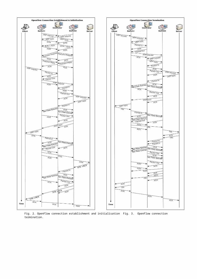
matched depending on the type of the packet. This typicallyincludes various match fields such as the MAC source address or IP destination address. Matching packets with flow tablehave two methods one is specific match and the other one is wildcards. For the specific matching, the packet arrives to the flow table with many identification fields such as source/destination address, MAC, Eth, TCP, IP, and exact port(s). Whereas the wildcards matching, receive packets and send it to any port(s), address, and destination and that with considering the identification (*), which means ANY. An OpenFlow switch must update the associate counters and apply the instruction set of only the highest priority flow entry that matches the packet [5]. Figure 2 shows the connection establishment and initialisation of OpenFlow switches usingpacket-in( ), packet-out( ) and flow-mod( ) functions as OMNeT++ messages. Through these functions the OpenFlow switches are initialised by flow entries and ready to match packets then send them to the destinations. Where the connection establishment is like TCP/IP through ARP Requestand Reply protocols.
The instructions specified in the associated flow entry are executed when a matching entry is found in a flow table. However, if an OpenFlow Switch receives a packet with no rule for matching flow entries in the flow table, depending on the switch configuration, the default is to send packets to the controller. The controller will first verify this flow against security policies. It can drop the packet, or it can install a flow entry directing every switch along the chosen path how to handle similar packets in the future [5]. Figure 3 shows the OpenFlow termination of connection by confirming the nodes’ position through ARP Request and Reply protocol then using Finalise packet to terminate the connection.
C. INET Framework for OMNeT++ SimulatorSimulation tools can provide more suitable task of
designing, building, and testing for users with practical feedback when developing real world systems. This will allow system designers to determine the correctness and efficiency of a design before the system is actually deployed.
OMNeT++ simulation is a discrete event simulator based on C++. The main benefit of OMNeT++ is simplifying the learning of integrating new modules as well as changing those already implemented [6]. The OMNeT++ environment has INET Framework, which is an open-source communication networks simulation package. The INET comprise of models for wired and wireless networking protocols such as Ethernet, IP, UDP, SCTP, TCP, IPv6 and many other protocol implementations, and several application models [7]. Recently, INET Framework has a new extension for OpenFlow model, which is a new toolbox for the simulation environment. This OpenFlow extension is still in the early development for INET Framework, currently based on switch specification version 1.2 [8]. It is also useful to explore the behaviour of these protocol models, capabilities and shortcomings further, by making use of simulations.
The packet header fields in the flow table lookups are
Fig. 2. OpenFlow connection establishment and initialisation Fig. 3. OpenFlow connection termination.
For this example, the distance between Brisbane and Sydney is 924 kilometres. The link delay for the distance channel can be calculated by following equations as we use a fiberoptic cable for distance communication. In more details, calculating the link delay of the mean (fiberoptic) is by dividing the distance between Australian states by the propagation speed of fiberoptic. Moreover, to calculate the propagation speed of fiberoptic is by dividing the speed of light by the refractive index of fiberoptic. On other words, the propagation speed of fiberoptic is equal to two third of speed of light, if we use the typical refractive index of fiberoptic onair which is 1.5 [8].
According to these 298 measurements, we convert the mean RTT per domain into seconds in order to show how well the domain is connected to other domains in regards to RTT. This is computed for both networks domains per run. The outcomes are one mean RTT value per domain and 8 mean RTT values in total. We also repeated each run five times with different random number seeds to exclude simulation artifacts.
VI. MEASUREMENT METHODOLOGY AND PERFORMANCERESULTS
The simulation was performed using OMNeT++.
The experiment results were arrived at after recording a large number of samples. To describe the measurement of the numbers, the standard deviation and mean value of RTT are computed. The mean of the RTT is assumed to be the average value and the standard deviation is approximated usingWhere is the delay of the wired (fiberoptic), d is the
This paper focuses on evaluating and analyzing networks performance and results, in this regards we use OMNeT++ network simulator. OMNeT++ has many advantages as a network simulator it’s been used widely in research academia fields because; it is able to simulate manufacturing, crowd management, airports and weather forecasting. OMNeT++ is scalable as its all simulated modules are implemented as C++ modules and they are linked together as a single process [7], [9], [10]. Moreover, OMNeT++ can modify parameters such as link bandwidth and delay also it is possible to modify configuration of network size, mobility pattern or speed for performance results corrections [11]. When time is concerned in OMNeT++ the performance results need to be repeated for correction and accuracy. OMNeT++ supports OpenFlow network as an extension of INET framework including spanning tree protocol (STP).
On the other hand, OMNeT++ has many limitations, one of those limitations regarding to OpenFlow protocol is that, it is old as the latest version of OpenFlow of this writing is 1.4 while currently in this paper we use OpenFlow switch specification 1.2 [12]. In addition, OMNeT++ uses C++ modules with its simulation engine code as well as all devices and objects as user-level executable program exactly as ns-3 network simulator [9], [13]. Meanwhile, NOX OpenFlow controller operations is a user-level program but, OMNeT++ and NOX cannot be compiled and linked together to form a single executable program [14]. For example, it is compulsory to create C++ module from scratch to build OpenFlow switch or controller, even ns-3 needs to build new modules for the same reason. Therefore, the re-implemented modules may not be the same as the behavior of real device/object with real applications, because the re-implemented module is a much- simplified abstraction of the real devices/objects. As OMNeT++ is supporting many functions such as STP, where STP is not supported by ns-3 as well as no TCP connection between simulated hosts, so in real model when use a TCP connection the results are conceders the packet losses and congestion [13], [15].
There are many other test-beds for observing the network communication such as EstiNet which combines between network simulator and emulator. However, emulator has limitations as it is only designed for real-time network functional testing. Whereas the simulation is for arbitrary scenarios, the feature that emulator can not do, so it does not scale very well [9]. The simulated module of OMNeT++ does not connect to real OpenFlow controller as an external entity for measuring the effects of the OpenFlow protocol where Mininet and EstiNet can do. The network emulator separates namespaces such as Mininet, which lead to reducing the overhead of the system rather being as one simulation process. Mininet is emulated hosts as virtualization approach. Mininet emulated hosts can run real application and can exchange information [16]. For example, one of these hosts can be a controller because of the controller is as a real application, also can be an OpenFlow switch or just a normal host which can link to other emulated devices using Ethernet pair (linux kernel).
experimental results on each run because of the emulated hostsrun based on CPU speed, current system activities, system load, memory bandwidth, number of emulated hosts andmultiplexing over the CPU [16]. For example, Mininet schedule packets promptly by the operating system, then it is not guarantee that all software OpenFlow switches will forward packets at the same rate of emulated hosts [9].
Mininet needs to run up a shell process to emulated each hosts and run up a user-space or kernel-space (OpenVswitch) to simulate each OpenFlow switch. Therefore Mininet is less scalable than EstiNet, ns-3 and OMNeT++. Mininet can only be used to study the behavior of the emulated hosts but cannot be used to study time of network/application performance. Mininet GUI can be used for observation purposes such as observing the packet playback of a simulation run and user needs to write Python code to set up and configure the simulation case. However, OMNeT++ has a GUI, which can be used for observation of results where users need to write C++ code to set up and configure the simulation case. Overall, it is better to use OMNeT++ even it takes time and effort to create simulations, though once modules are created, it's much easier to create new ones [17].
V. SIMULATION SETUP FOR EXPERIMENTATION
This section presents the simulation scenarios of the OpenFlow module in terms of analysing the results, to find out which model behaves faster and more efficient. In addition, we accumulate the simulation scenarios by studying performance metrics with respect to the round-trip-time and its mean.
Fig. 4. TCP/IP vs.OpenFlow Domain
A. Simulation ScenariosIn this evaluation, we use the same topology for both
networks, which represents Australian states as shown in Fig.5. This Australian topology was created with 8 locations, representing state capital cities by cloud domains for OpenFlow scenarios. Where the OpenFlow cloud domain comprises of one host, one OpenFlow switch, and externally connected to a device called controller (standard server). The controller is placed in the network and directly connected via aseparate link to the different OpenFlow switches (see Fig.4). In addition, this single OpenFlow controller also hasconnections through separate control links to all 8 state domains. Within each network topology, a new OMNeT++ channel type is defined (distance channel) to connect these different network state domains. For example:
Brisbane.ethg++ <-->distance = 924km <--> Sydney.ethg++;

IV. RELATED WORKS Network emulator has unpredictable results and different
distance, and is the propagation speed of fiberoptic. following equation [19]:
(3) (2)
Where is the propagation speed of fiberoptic, c is the speed
of light, and is the refractive index of fiberoptic.
Fig. 5. Australian states topology
The simulation scenarios of the OpenFlow module is executed and the outcomes from these tests will be compared with each other. To perform measurement the host needs to initiate the transmission of data and another end-host to receive the data, performing a minor computation and sends back a response.
B. Performance MetricAs the performance metric for our evaluation is the mean
round-trip-time (RTT) for the nodes in the investigated networks. Each host contains some modification in the ping application. For every echo request message sent, the application will choose a random host out of the available 8 domains [8], [18]. We then measure the RTT for the received echo reply message. Once a ping has finished, after two seconds the application will then start again the next ping to another random host. We set each run with the simulation time of 300 seconds, which results in 149 RTT measurements per OpenFlow domain.
Where T is the packet transmission time between segments sent and receives an acknowledgement arrival (second), N is the packet size (bits), and R is the data rate bandwidth (bit/second).
To calculate the packet transmission time we need to divide the packet size which known in our simulation by 1500 bytes by the data rate bandwidth that we have defined in our network three kinds of channels as following:
EthernetLine with data rate 100 Mbit/s that connects between nodes within domain, DistanceChannel with data rate 10Gbit/s that connects between domains, and BackboneLinewith data rate 40 Gbit/s that connects between domains and central controller.
Data rate bandwidth Data rate bandwidth in bits
EthernetLine 100 Mbit/s
DistanceChannel 10 Gbit/s
BackboneLine 40 Gbit/s
Then we need to calculate the round trip time RTT by the following equation:
(4)
Where Δ is the round trip time RTT (second), α is the
smoothing factor, is the old round trip time RTT, and T is the packet transmission time.
Then we can calculate the round trip time RTT by α (value between 0 and 1) which is equals to the value 0.875 multiplying with the old round trip time as the top equation and then multiplying with T which is the transmission time between the segments sent and the acknowledgement arrival found from equation (3).
For this example, the distance between Brisbane and Sydney is 924 kilometres. The link delay for the distance channel can be calculated by following equations as we use a fiberoptic cable for distance communication. In more details, calculating the link delay of the mean (fiberoptic) is by dividing the distance between Australian states by the propagation speed of fiberoptic. Moreover, to calculate the propagation speed of fiberoptic is by dividing the speed of light by the refractive index of fiberoptic. On other words, the propagation speed of fiberoptic is equal to two third of speed of light, if we use the typical refractive index of fiberoptic onair which is 1.5 [8].
According to these 298 measurements, we convert the mean RTT per domain into seconds in order to show how well the domain is connected to other domains in regards to RTT. This is computed for both networks domains per run. The outcomes are one mean RTT value per domain and 8 mean RTT values in total. We also repeated each run five times with different random number seeds to exclude simulation artifacts.
VI. MEASUREMENT METHODOLOGY AND PERFORMANCERESULTS
The simulation was performed using OMNeT++.
The experiment results were arrived at after recording a large number of samples. To describe the measurement of the numbers, the standard deviation and mean value of RTT are computed. The mean of the RTT is assumed to be the average value and the standard deviation is approximated usingWhere is the delay of the wired (fiberoptic), d is the
ACKNOWLEDGMENT
This work is sponsored by the Centre for Real-TimeInformation Networks (CRIN) in the Faculty of Engineering& Information Technology at the University of Technology, Sydney (UTS).
REFERENCES
Fig. 6. Performance Based on Controller location (A)
Fig. 7. Performance Based on Controller location (B)
The results in Figure 6 and Figure 7 show the measured scalar values for different controller locations. It can be seen that the OpenFlow performance is affected by the placement of the central controller. For example, the second and the fifth domain, Sydney and Perth, where the controller was placed closer to Sydney then the result for this domain is better than Perth. These differences are caused by the placement of the central controller.
VII. CONCLUSION AND FUTURE WORKS
This paper has presented network metrics and topologies of our study, followed by evaluating the performance of the OpenFlow protocol. The results indicate that the performance of the OpenFlow network was affected by the placement of the central controller
As for future studies, we will extend OpenFlow model to a more sophisticated architecture so that it can be used for distributed communication environment based on intelligent agents to exchange information. Therefore, it could be deployed to many different environments such as fire alarming and road traffic systems.
[1] N. McKeown, T. Anderson, H. Balakrishnan, G. Parulkar, L. Peterson, J.Rexford, S. Shenker and J. Turner, “OpenFlow: Enabling Innovation inCampus Networks” SIGCOMM Computer Communication Rev., Vol.38, March 2008, pp. 69-74.
[2] B. A. Forouzan, TCP/IP protocol suite: McGraw-Hill, Inc., 2002.[3] ONF White Paper. Software-Defined Networking: The New Norm for
Networks. April 2012.[4] R. Stewart and C. Metz, "SCTP: new transport protocol for TCP/IP,"
Internet Computing, IEEE, vol. 5, pp. 64-69, 2001.[5] ONF, 2012, “Open network foundation, openflow switch specification
version 1.3.0 ( wire protocol 0x04 ) viewed 20-08-2012 www.opennetworking.org/images/stories/downloads/specification/openf low-spec-v1.3.0.pdf.”
[6] A. Varga, "The OMNeT++ discrete event simulation system," inProceedings of the European Simulation Multiconference (ESM’2001),2001, p. 185.
[7] A. Varga and R. Hornig, "An overview of the OMNeT++ simulation environment," in Proceedings of the 1st international conference on Simulation tools and techniques for communications, networks and systems & workshops, 2008, p. 60.
[8] D. Klein and M. Jarschel, "An OpenFlow Extension for the OMNeT++ INET Framework," OMNeT++ 2013, Cannes France, March 2013.
[9] Wang, S.-Y., C.-L. Chou, and Chun-Ming Yang, EstiNet openflow network simulator and emulator, in Communications Magazine. 2013, IEEE. p. 110-117.
[10] A. Varga, Omnet++ user manual. OMNeT++ Discrete Event Simulation System. Available at: http://www. omnetpp. org/doc/manual/usman. html, 2010.
[11] A. Varga. INET Framework for the OMNeT++ Discrete EventSimulator. http://github.com/inet-framework/inet, 2012.
[12] OpenFlow Switch Consortium. "OpenFlow Switch SpecificationVersion 1.0. 0." (2009).
[13] NS-3 version 3.16. OpenFlow switch support. http://www.nsnam.org/docs/release/3.16/models/html/openflow- switch.html, Dec 2012.
[14] N. Gude, T. Koponen, J. Pettit, B. Pfaff, M. Casado, N. McKeown, and S. Shenker. NOX: towards an operating system for networks. SIGCOMM Comput. Commun. Rev., 38(3):105–110, Jul 2008.
[15] K. Fall and S. Floyd, "Simulation-based comparisons of Tahoe, Reno and SACK TCP," ACM SIGCOMM Computer Communication Review, vol. 26, pp. 5-21, 1996.
[16] B. Lantz, et al., "A network in a laptop: rapid prototyping for software- defined networks," in Proceedings of the 9th ACM SIGCOMM Workshop on Hot Topics in Networks, 2010, p. 19.
[17] Chamberlain, T., Learning OMNeT++. 2013: Packt Publishing Ltd.[18] I. Jeroen, G. Heijenk and P. T. de Boer. "TCP/IP modelling in
OMNeT+.", Univers ity of Twente, The Netherlands, July 2004.[19] D. Sünnen, “Performance Evaluation of OpenFlow Switches,” Semester
Thesis at the Department of Information Technology and Electrical Engineering, 2011.