PAPER SmartCameraNetworksin - UCLAweb.cs.ucla.edu/~dt/papers/pieee08/pieee08.pdf · 1...
17
INVITED PAPER 1 Smart Camera Networks in 2 Virtual Reality 3 Simulated smart cameras track the movement of simulated pedestrians in 4 a simulated train station, allowing development of improved 5 control strategies for smart camera networks. 6 By Faisal Qureshi, Member IEEE , and Demetri Terzopoulos, Fellow IEEE 7 ABSTRACT | This paper presents our research towards smart 8 camera networks capable of carrying out advanced surveil- 9 lance tasks with little or no human supervision. A unique 10 centerpiece of our work is the combination of computer 11 graphics, artificial life, and computer vision simulation tech- 12 nologies to develop such networks and experiment with them. 13 Specifically, we demonstrate a smart camera network com- 14 prising static and active simulated video surveillance cameras 15 that provides extensive coverage of a large virtual public space, 16 a train station populated by autonomously self-animating 17 virtual pedestrians. The realistically simulated network of 18 smart cameras performs persistent visual surveillance of 19 individual pedestrians with minimal intervention. Our innova- 20 tive camera control strategy naturally addresses camera 21 aggregation and handoff, is robust against camera and 22 communication failures, and requires no camera calibration, 23 detailed world model, or central controller. 24 KEYWORDS | Camera networks; computer vision; persistent 25 human observation; sensor networks; smart cameras; virtual 26 reality; visual surveillance 27 I. INTRODUCTION 28 Future visual sensor networks will rely on smart cameras 29 for sensing, computation, and communication. Smart 30 cameras are self-contained vision systems, complete with 31 increasingly sophisticated image sensors, power circuitry, 32 (wireless) communication interfaces, and on-board pro- 33 cessing and storage capabilities. They provide new 34 opportunities to develop camera sensor networks capable 35 of effective visual coverage of extensive areasVpublic 36 spaces, disaster zones, battlefields, and even entire 37 ecosystems. These multicamera systems lie at the inter- 38 section of Computer Vision and Sensor Networks, raising 39 research problems in the two fields that must be addressed 40 simultaneously. 41 In particular, as the size of the network grows, it 42 becomes infeasible for human operators to monitor the 43 multiple video streams and identify all events of possible 44 interest, or even to control individual cameras directly in 45 order to maintain persistent surveillance. Therefore, it 46 is desirable to design camera sensor networks that are 47 capable of performing advanced visual surveillance tasks 48 autonomously, or at least with minimal human 49 intervention. 50 In this paper, we demonstrate a model smart camera 51 network comprising uncalibrated, static and active, simu- 52 lated video surveillance cameras that, with minimal 53 operator assistance, provide perceptive coverage of a large 54 virtual public spaceVa train station populated by auton- 55 omously self-animating virtual pedestrians (Fig. 1). Once a 56 pedestrian of interest is selected either automatically by 57 the system or by an operator monitoring surveillance video 58 feeds, the cameras decide among themselves how best to 59 observe the subject. For example, a subset of the active 60 pan/tilt/zoom (PTZ) cameras can collaboratively monitor 61 the pedestrian as he or she weaves through the crowd. The 62 problem of assigning cameras to persistently observe 63 pedestrians becomes even more challenging when multi- 64 ple pedestrians are involved. To deal with the myriad 65 possibilities, the cameras must be able to reason about the 66 dynamic situation. To this end, we propose a distributed 67 camera network control strategy that is capable of Manuscript received December 4, 2007; revised April 13, 2008. Current version published 00/00/2008. This work was made possible in part by a grant from the Defense Advanced Research Projects Agency (DARPA) of the U.S. Department of Defense. F. Qureshi is with the Faculty of Science, University of Ontario Institute of Technology, Oshawa, ON, L1H 7K4, Canada (e-mail: [email protected]). D. Terzopoulos is with the Computer Science Department, University of California, Los Angeles, CA 90095-1596 USA (e-mail: [email protected]). Digital Object Identifier: 10.1109/JPROC.2008.928932 Vol. 96, No. 10, October 2008 | Proceedings of the IEEE 1 0018-9219/$25.00 Ó2008
Transcript of PAPER SmartCameraNetworksin - UCLAweb.cs.ucla.edu/~dt/papers/pieee08/pieee08.pdf · 1...
INV ITEDP A P E R
1 Smart Camera Networks in2 Virtual Reality3 Simulated smart cameras track the movement of simulated pedestrians in
4 a simulated train station, allowing development of improved
5 control strategies for smart camera networks.
6 By Faisal Qureshi, Member IEEE, and Demetri Terzopoulos, Fellow IEEE
7 ABSTRACT | This paper presents our research towards smart
8 camera networks capable of carrying out advanced surveil-
9 lance tasks with little or no human supervision. A unique
10 centerpiece of our work is the combination of computer
11 graphics, artificial life, and computer vision simulation tech-
12 nologies to develop such networks and experiment with them.
13 Specifically, we demonstrate a smart camera network com-
14 prising static and active simulated video surveillance cameras
15 that provides extensive coverage of a large virtual public space,
16 a train station populated by autonomously self-animating
17 virtual pedestrians. The realistically simulated network of
18 smart cameras performs persistent visual surveillance of
19 individual pedestrians with minimal intervention. Our innova-
20 tive camera control strategy naturally addresses camera
21 aggregation and handoff, is robust against camera and
22 communication failures, and requires no camera calibration,
23 detailed world model, or central controller.
24 KEYWORDS | Camera networks; computer vision; persistent
25 human observation; sensor networks; smart cameras; virtual
26 reality; visual surveillance
27 I . INTRODUCTION
28 Future visual sensor networks will rely on smart cameras29 for sensing, computation, and communication. Smart30 cameras are self-contained vision systems, complete with
31increasingly sophisticated image sensors, power circuitry,
32(wireless) communication interfaces, and on-board pro-
33cessing and storage capabilities. They provide new
34opportunities to develop camera sensor networks capable
35of effective visual coverage of extensive areasVpublic
36spaces, disaster zones, battlefields, and even entire37ecosystems. These multicamera systems lie at the inter-
38section of Computer Vision and Sensor Networks, raising
39research problems in the two fields that must be addressed
40simultaneously.
41In particular, as the size of the network grows, it
42becomes infeasible for human operators to monitor the
43multiple video streams and identify all events of possible
44interest, or even to control individual cameras directly in45order to maintain persistent surveillance. Therefore, it
46is desirable to design camera sensor networks that are
47capable of performing advanced visual surveillance tasks
48autonomously, or at least with minimal human
49intervention.
50In this paper, we demonstrate a model smart camera
51network comprising uncalibrated, static and active, simu-
52lated video surveillance cameras that, with minimal53operator assistance, provide perceptive coverage of a large
54virtual public spaceVa train station populated by auton-
55omously self-animating virtual pedestrians (Fig. 1). Once a
56pedestrian of interest is selected either automatically by
57the system or by an operator monitoring surveillance video
58feeds, the cameras decide among themselves how best to
59observe the subject. For example, a subset of the active
60pan/tilt/zoom (PTZ) cameras can collaboratively monitor61the pedestrian as he or she weaves through the crowd. The
62problem of assigning cameras to persistently observe
63pedestrians becomes even more challenging when multi-
64ple pedestrians are involved. To deal with the myriad
65possibilities, the cameras must be able to reason about the
66dynamic situation. To this end, we propose a distributed
67camera network control strategy that is capable of
Manuscript received December 4, 2007; revised April 13, 2008. Current version
published 00/00/2008. This work was made possible in part by a grant
from the Defense Advanced Research Projects Agency (DARPA) of the
U.S. Department of Defense.
F. Qureshi is with the Faculty of Science, University of Ontario Institute of Technology,
Oshawa, ON, L1H 7K4, Canada (e-mail: [email protected]).
D. Terzopoulos is with the Computer Science Department, University of California,
Los Angeles, CA 90095-1596 USA (e-mail: [email protected]).
Digital Object Identifier: 10.1109/JPROC.2008.928932
Vol. 96, No. 10, October 2008 | Proceedings of the IEEE 10018-9219/$25.00 �2008
68 dynamic, task-driven node aggregation through local
69 decision-making and internode communication.
70 A. Virtual Vision71 The type of research that we report here would be very
72 difficult to carry out in the real world given the expense of
73 deploying and experimenting with an appropriately
74 complex smart camera network in a large public space75 such as an airport or a train station. Moreover, privacy laws
76generally restrict the monitoring of people in public spaces
77for experimental purposes.1 To bypass the legal and cost
78impediments, we advocate virtual vision, a unique synthesis
79of computer graphics, artificial life, and computer vision
80technologies (Fig. 2). Virtual vision is an advanced
81simulation framework for working with machine vision
Fig. 1. Plan view of the (roofless) virtual Penn Station environment, revealing the concourses and train tracks (left), the main waiting
room (center), and the shopping arcade (right). (The yellow rectangles indicate pedestrian portals.) An example camera network is illustrated,
comprising 16 simulated active (PTZ) video surveillance cameras. Synthetic images from cameras 1, 7, and 9 (from [1]).
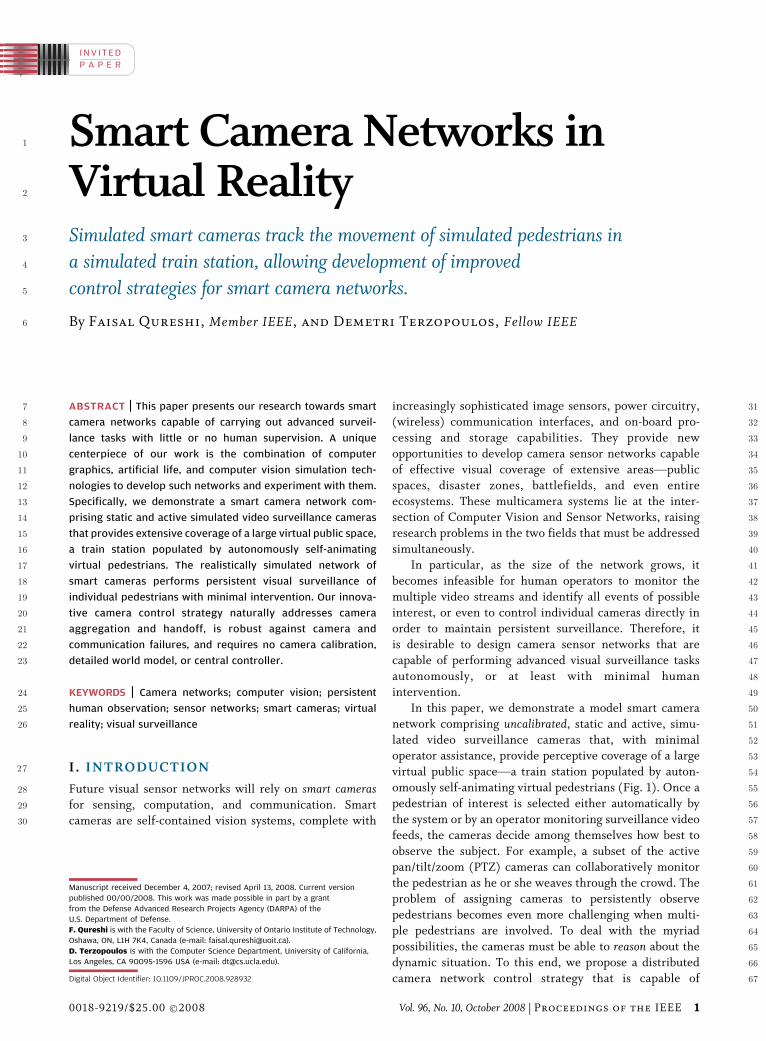
Fig. 2. The virtual vision paradigm (image from [1]).
1See [2] for a discussion of privacy issues related to smart cameranetworks.
Qureshi and Terzopoulos: Smart Camera Networks in Virtual Reality
2 Proceedings of the IEEE | Vol. 96, No. 10, October 2008
82 systems, including smart camera networks, that also offers
83 wonderful rapid prototyping opportunities. Exploiting84 visually and behaviorally realistic environments, called
85 reality emulators, virtual vision offers significantly greater
86 flexibility and repeatability during the camera network
87 design and evaluation cycle, thus expediting the scientific
88 method and system engineering process.
89 In our work, we employ a virtual train station populated
90 by autonomous, lifelike virtual pedestrians, wherein we
91 deploy virtual cameras that generate synthetic video feeds92 emulating those acquired by real surveillance cameras
93 monitoring public spaces (Fig. 3). Despite its sophistication,
94 our simulator runs on high-end commodity PCs, thereby
95 obviating the need to grapple with special-purpose hardware
96 and software. Unlike the real world, 1) the multiple virtual
97 cameras are very easily reconfigurable in the virtual space,
98 2) we can readily determine the effect of algorithm and
99 parameter modifications because experiments are perfectly100 repeatable in the virtual world, and 3) the virtual world
101 provides readily accessible ground-truth data for the pur-
102 poses of camera network algorithm validation. It is important
103 to realize that our simulated camera networks always run
104 online in real time within the virtual world, with the virtual
105 cameras actively controlled by the vision algorithms. By
106 suitably prolonging virtual-world time relative to real-world
107 time, we can evaluate the competence of computationally108 expensive algorithms, thereby gauging the potential payoff of
109 efforts to accelerate them through efficient software and/or
110 dedicated hardware implementations.
111 An important issue in camera network research is the
112 comparison of camera control algorithms. Simple video
113 capture suffices for gathering benchmark data from time-
114 shared physical networks of passive, fixed cameras, but
115 gathering benchmark data for networks that include any
116smart, active PTZ cameras requires scene reenactment for
117every experimental run, which is almost always infeasible118when many human subjects are involved. Costello et al. [3],
119who compared various schemes for scheduling an active
120camera to observe pedestrians, ran into this hurdle and
121resorted to Monte Carlo simulation to evaluate camera
122scheduling approaches. They concluded that evaluating
123scheduling policies on a physical testbed comprising even a
124single active camera is extremely problematic. By offering
125convenient and limitless repeatability, our virtual vision126approach provides a vital alternative to physical active
127camera networks for experimental purposes.
128Nevertheless, skeptics may argue that virtual vision
129relies on simulated data, which can lead to inaccurate
130results. Fretting that virtual video lacks all the subtleties of
131real video, some may cling to the dogma that it is
132impossible to develop a working machine vision system
133using simulated video. However, our high-level camera134control routines do not directly process any raw video.
135Instead, these routines are realistically driven by data
136supplied by low-level recognition and tracking routines
137that mimic the performance of a state-of-the-art pedestrian
138localization and tracking system, including its limitations
139and failure modes. This enables us to develop and evaluate
140camera network control algorithms under realistic simu-
141lated conditions consistent with physical camera networks.142We believe that the fidelity of our virtual vision emulator is
143such that algorithms developed through its use will readily
144port to the real world.
145B. Smart Camera Network146Many of the challenges associated with sensor net-
147works are relevant to our work. A fundamental issue is the
148selection of sensor nodes that should participate in a
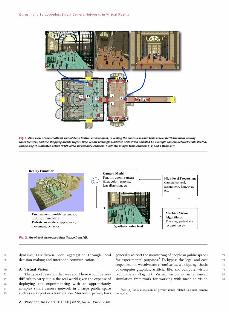
Fig. 3. Synthetic video feeds from multiple virtual surveillance cameras situated in the (empty) Penn Station environment.
Camera locations are shown in Fig. 1.
Qureshi and Terzopoulos: Smart Camera Networks in Virtual Reality
Vol. 96, No. 10, October 2008 | Proceedings of the IEEE 3
149 particular sensing task [4]. The selection process must take150 into account the informational contribution of each node
151 against its resource consumption or potential utility in
152 other tasks. Distributed approaches for node selection are
153 preferable to centralized approaches and offer what are
154 perhaps the greatest advantages of networked sensingV155 robustness and scalability. Also, in a typical sensor
156 network, each node has local autonomy and can commu-
157 nicate with a small number of neighboring nodes, where158 the neighborhood of a node can be defined automatically
159 as the set of nodes that are, e.g., within nominal radio
160 communications distance of that node [5]. Message delay
161 and message loss are common occurrences in sensor
162 networks due to bandwidth limitations, interference, etc.
163 One must also contend with nonstationary network topol-
164 ogy due to node failures, node additions, etc.
165 Mindful of these issues, we propose a novel camera166 network control strategy that does not require camera
167 calibration, or a detailed world model, or a central con-
168 troller. The overall behavior of the network is the conse-
169 quence of the local processing at each node and internode
170 communication. The network is robust to node and
171 communication failures. Moreover, it is scalable because
172 of the lack of a central controller. Visual surveillance tasks
173 are performed by groups of one or more camera nodes.174 These groups, which are created on the fly, define the
175 information sharing parameters and the extent of collab-
176 oration between nodes. A group evolvesVi.e., old nodes
177 leave the group and new nodes join itVduring the lifetime
178 of the surveillance task. One node in each group acts as the
179 group supervisor and is responsible for group-level deci-
180 sion making. We also present a novel constraint satisfac-
181 tion problem formulation for resolving interactions182 between groups.
183 We assume the following communication model:
184 1) nodes can communicate with their neighbors, 2) mes-
185 sages from one node can be delivered to another node if
186 there is a path between the two nodes, and 3) messages
187 can be sent from one node to all the other nodes.
188 Furthermore, we assume the following network model:
189 1) messages can be delayed, 2) messages can be lost, and190 3) nodes can fail. These assumptions ensure that our
191 virtual camera network faithfully mimics the operational
192 characteristic of a real sensor network.
193 C. Contributions and Overview194 The contribution of this paper is twofold. We introduce
195 a novel camera sensor network framework suitable for
196 next-generation visual surveillance applications. We also197 demonstrate the advantages of developing and evaluating
198 camera sensor networks within our sophisticated virtual
199 reality simulation environment. A preliminary version of
200 this work appeared in [6] and it extends that reported in an
201 earlier paper [7]. Among other extensions, we introduce a
202 novel Constraint Satisfaction Problem (CSP) formulation
203 for resolving group–group interactions.
204The remainder of the paper is organized as follows:205Section II reviews relevant prior work. We explain the low-
206level vision emulation and behavior models for camera
207nodes in Section III. Section IV presents the sensor
208network communication model. Section V discusses the
209application of the model in the context of persistent visual
210surveillance and presents our results. Section VI concludes
211the paper and discusses future research directions.
212II . RELATED WORK
213In 1997, Terzopoulos and Rabie introduced a purely
214software-based approach to designing active vision sys-
215tems, called animat vision [8]. Their approach prescribes
216the use of artificial animals (or animats) situated in
217physics-based virtual worlds to study and develop active
218vision systems, rather than struggling with hardwareVthe219cameras and wheeled mobile robots typically used by
220computer vision researchers. They demonstrated the
221animat vision approach by implementing biomimetic
222active vision systems for virtual animals and humans [9].
223The algorithms developed were later adapted for use in a
224vehicle tracking and traffic control system [10], which
225affirmed the usefulness of the animat vision approach in
226designing and evaluating complex computer vision227systems.
228Envisioning a large computer-simulated world inhab-
229ited by virtual humans that look and behave like real
230humans, Terzopoulos [11] then proposed the idea of using
231such visually and behaviorally realistic environments,
232which he called reality emulators, to design machine
233vision systems, particularly surveillance systems. The work
234presented here is a significant step towards realizing this235vision. Shao and Terzopoulos [1] developed a prototype
236reality emulator, comprising a reconstructed model of the
237original Pennsylvania Station in New York City populated
238by virtual pedestrians, autonomous agents with functional
239bodies and brains. The simulator incorporates a large-scale
240environmental model of the train station with a sophisti-
241cated pedestrian animation system including behavioral,
242perceptual, and cognitive human simulation algorithms.243The simulator can efficiently synthesize well over 1000
244self-animating pedestrians performing a rich variety of
245activities in the large-scale indoor urban environment.
246Like real humans, the synthetic pedestrians are fully auto-
247nomous. They perceive the virtual environment around
248them, analyze environmental situations, make decisions,
249and behave naturally within the train station. They can
250enter the station, avoiding collisions when proceeding251through congested areas and portals, queue in lines as
252necessary, purchase train tickets at the ticket booths in the
253main waiting room, sit on benches when tired, obtain
254food/drinks from vending machines when hungry/thirsty,
255etc., and eventually proceed to the concourses and descend
256stairs to the train platforms. Standard computer graphics
257techniques render the busy urban scene with considerable
Qureshi and Terzopoulos: Smart Camera Networks in Virtual Reality
4 Proceedings of the IEEE | Vol. 96, No. 10, October 2008
258 geometric and photometric detail (Fig. 1). Our camera259 network is deployed and tested within this virtual train
260 station simulator.
261 In concordance with the virtual vision paradigm,
262 Santuari et al. [12], [13] advocate the development and
263 evaluation of pedestrian segmentation and tracking
264 algorithms using synthetic video generated within a virtual
265 museum simulator containing scripted animated charac-
266 ters. Synthetic video is generated via rendering, which267 supports global illumination, shadows, and visual artifacts
268 like depth of field, motion blur, and interlacing. They have
269 used their virtual museum environment to develop static
270 background modeling, pedestrian segmentation, and
271 pedestrian tracking algorithms. They focus on low-level
272 computer vision, whereas our work goes beyond this to
273 focus on high-level computer vision issues, especially mul-
274 ticamera control in large-scale camera networks. Previous275 work on multicamera systems has dealt with issues related
276 to low- and medium-level computer vision, namely,
277 identification, recognition, and tracking of moving objects
278 [14]–[18]. The emphasis has been on tracking and on
279 model transference from one camera to another, which is
280 required for object identification across multiple cameras
281 [19]. Multiple cameras have also been employed either to
282 increase the reliability of the tracking algorithm [20] (by283 overcoming the effects of occlusion or by using three-
284 dimensional (3-D) information for tracking) or to track an
285 object as it moves through the fields of view (FOVs) of
286 different cameras. In most cases, object tracking is accom-
287 plished by combining some sort of background subtraction
288 strategy and an object appearance/motion model [21].
289 Numerous researchers have proposed camera network
290 calibration to achieve robust object identification and291 classification from multiple viewpoints, and automatic
292 camera network calibration strategies have been proposed
293 for both stationary and actively controlled camera nodes
294 [22]–[24]. Schemes for learning sensor (camera) network
295 topologies have also been proposed [25]–[27].
296 Little attention has been paid, however, to the problem
297 of controlling or scheduling active cameras when there are
298 more objects to be monitored in the scene than there are299 active cameras. Some researchers employ a stationary wide-
300 FOV camera to control an active camera [3], [28]–[30].
301 Generally speaking, the cameras are assumed to be cali-
302 brated and the total coverage of the cameras is restricted to
303 the FOV of the stationary camera. In contrast, our approach
304 does not require calibration; however, we assume that the
305 cameras can identify a pedestrian with reasonable accuracy.
306 To this end, we employ color-based pedestrian appearance307 models.
308 The problem of forming sensor groups based on task
309 requirements and resource availability has received much
310 attention within the sensor networks community [4].
311 Mallet [27] argues that task-based grouping in ad hoc camera
312 networks is highly advantageous. Collaborative tracking,
313 which subsumes this issue, is considered an essential
314capability in many sensor networks [4]. Zhao et al. [31]315introduce an information driven approach to collaborative
316tracking that attempts to minimize the energy expenditure
317at each node by reducing internode communication. A node
318selects the next node by utilizing the information gain
319versus energy expenditure tradeoff estimates for its
320neighbor nodes. In the context of camera networks, it is
321often difficult without explicit geometric and camera
322calibration knowledge for a camera node to estimate the323expected information gain of assigning another camera to
324the task, but such knowledge is tedious to obtain and
325maintain during the lifetime of the camera network.
326Therefore, our camera networks eschew such knowledge;
327a node need only communicate with nearby nodes before
328selecting new nodes.
329The nodes in sensor networks are usually untethered
330sensing units with limited onboard power reserves. Hence,331a crucial concern is the energy expenditure at each node,
332which determines the lifespan of a sensor network [32].
333Node communications have large power requirements;
334therefore, sensor network control strategies attempt to
335minimize the internode communication [31]. Presently,
336we do not address this issue; however, the communication
337protocol that we propose limits the communication to the
338active nodes and their neighbors. IrisNet is a sensor339network architecture tailored towards advanced sensors
340connected via high-capacity communication channels [33].
341It takes a centralized view of the network, modeling it as a
342distributed database that allows efficient access to sensor
343readings. We consider this work to be orthogonal to ours.
344SensEye is a recent sensor-network inspired multicamera
345system [34]. It demonstrates the low latency and energy
346efficiency benefits of a multitiered network, where each347tier defines a set of sensing capabilities and corresponds to
348a single class of smart camera sensors. However, SensEye
349does not deal with the distributed camera control issues
350that we address.
351Our node grouping strategy is inspired by the
352ContractNet distributed problem solving protocol [35]
353and it realizes group formation via internode negotiation.
354Unlike Mallett’s [27] approach to node grouping, where355groups are defined implicitly via membership nodes, our
356approach defines groups explicitly through group leaders.
357This simplifies reasoning about groups; e.g., Mallett’s
358approach requires specialized nodes for group termination.
359Our strategy handles group leader failures through group
360merging and group leader demotion operations.
361Resolving group–group interactions requires sensor
362assignment to various tasks, which shares many features363with Multi-Robot Task Allocation (MRTA) problems
364studied by the multiagent systems community [36].
365Specifically, according to the taxonomy provided in [36],
366our sensor assignment formulation belongs to the single-
367task (ST) robots, multirobot (MR) tasks, instantaneous
368assignment (IA) category. ST–MR–IA problems are signi-
369ficantly more difficult than single-robot-task MRTA
Qureshi and Terzopoulos: Smart Camera Networks in Virtual Reality
Vol. 96, No. 10, October 2008 | Proceedings of the IEEE 5
370 problems. Task-based robot grouping arises naturally in371 ST–MR–IA problems, which are sometimes referred to as
372 coalition formation. ST–MR–IA problems have been ex-
373 tensively studied and they can be reduced to a set parti-
374 tioning problem (SPP), which is strongly NP-hard [37].
375 However, heuristics-based set partitioning algorithms exist
376 that produce good results on large SPPs [38]. Fortunately,
377 the sizes of MRTA problems, and by extension SPPs,
378 encountered in our camera sensor network setting are379 small because of the spatial or locality constraints inherent
380 to the camera sensors.
381 We model sensor assignments as a CSP, which we solve
382 using Bcentralized[ backtracking. Each sensor assignment
383 that passes the hard constraints is assigned a weight, and
384 the assignment with the highest weight is selected. We
385 have intentionally avoided distributed constraint optimi-
386 zation techniques (e.g., [39] and [40]) because of their387 explosive communication requirements even for small
388 sized problems. Additionally, it is not obvious how they
389 handle node and communication failures. Our strategy lies
390 somewhere between purely distributed and fully central-
391 ized schemes for sensor assignmentVsensor assignment is
392 distributed at the level of the network, whereas it is
393 centralized at the level of a group.
394 III . SMART CAMERA NODES
395 Each virtual camera node in the sensor network is able to
396 perform low-level visual processing and is an active sensor
397 with a repertoire of camera behaviors. The virtual cameras
398 also render the scene to generate synthetic video suitable
399 for machine vision processing. Sections III-A–D describe
400 each of these aspects of a camera node.
401 A. Synthetic Video402 Virtual cameras use the OpenGL library and standard
403 graphics pipeline [41] to render the synthetic video feed.
404 Our imaging model emulates imperfect camera color re-
405 sponse, compression artifacts, detector and data drop-out
406 noise, and video interlacing; however, we have not yet
407 modeled other imaging artifacts such as depth-of-field,408 vignetting, and chromatic aberration. Furthermore, the
409 rendering engine does not yet support pedestrian shadows
410 and specular highlights. More sophisticated rendering
411 schemes would address these limitations. Noise is intro-
412 duced during a post-rendering phase. The amount of noise
413 introduced into the process determines the quality of the
414 input to the visual analysis routines and affects the perform-
415 ance of the pedestrian segmentation and tracking module.416 We model the variation in color response across cam-
417 eras by manipulating the Hue, Saturation, Value (HSV)
418 channels of the rendered image. Similarly, we can adjust
419 the tints, tones, and shades of an image by adding the
420 desired amounts of blacks, whites, and grays, respectively
421 [42]. Our visual analysis routines rely on color-based
422 appearance models to track pedestrians; hence, camera
423handovers are sensitive to variations in the color response
424of different cameras.
425Bandwidth is generally at a premium in sensor net-
426works, especially so in camera networks. In many in-
427stances, images captured by camera nodes are transmitted428to a central location for analysis, storage, and monitoring
429purposes. Camera nodes routinely exchange information
430among themselves during camera handover, camera
431coordination, and multicamera sensing operations. The
432typical data flowing in a camera network is image/video
433data, which places much higher demands on a network
434infrastructure than, say, alphanumeric or voice data.
435Consequently, in order to keep the bandwidth require-436ments within acceptable limits, camera nodes compress
437the captured images and video before sending them off to
438other camera nodes or to the monitoring station.
439Compression artifacts together with the low resolution
440of the captured images/video pose a challenge to visual
441analysis routines and are therefore relevant to camera
442network research. We introduce compression effects into
443the synthetic video by passing it through a JPEG444compression/decompression stage before providing it to
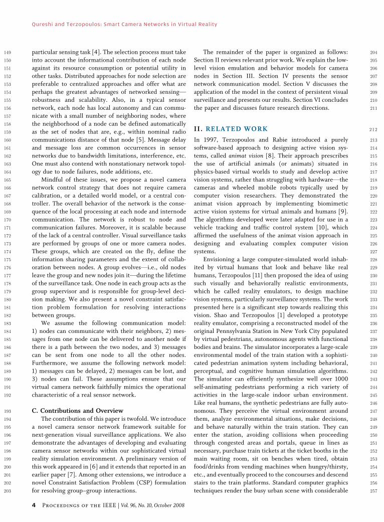
445the pedestrian recognition and tracking module. Fig. 4
446shows compressed and uncompressed versions of a
4471000� 1000 image. The compressed version (24 kb) is
448about 10 times smaller than the uncompressed version
449(240 kb). Notice the compression artifacts around the
450color region boundaries in Fig. 4(d).
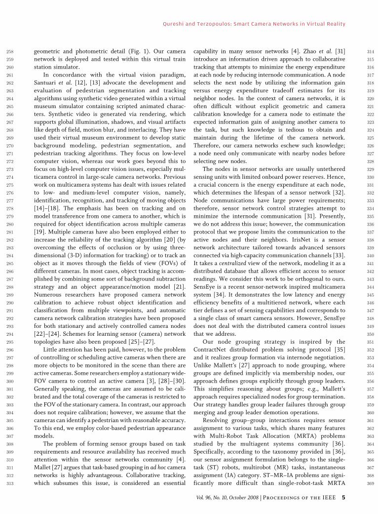
451We simulate detector noise as a data-independent,452additive process with a zero-mean Gaussian distribution
453[Fig. 5(a)]. The standard deviation of the Gaussian distri-
454bution controls the amount of noise introduced into the
455image. Data dropout noise is caused by errors during data
456transmission within the imaging device [Fig. 5(b)]. The
457corrupted pixels are either set to the maximum value
458(snow) or have their bits flipped. Sometimes pixels are
459alternatively set to the maximum value or zero (salt and460pepper noise). The amount of noise is determined by the
461percentage of corrupted pixels.
462We simulate interlaced video by rendering frames at
463twice the desired frequency and interlacing the even and
Fig. 4. Compression artifacts in synthetic video. (a) Uncompressed
image. (b) Enlarged region of the rectangular box in (a).
(c) JPEG-compressed image. (d) Enlarged region of the
rectangular box in (c).
Qureshi and Terzopoulos: Smart Camera Networks in Virtual Reality
6 Proceedings of the IEEE | Vol. 96, No. 10, October 2008
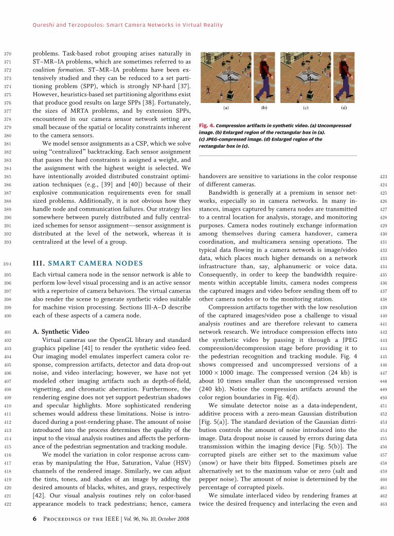
464 odd rows of sequential frames. Fig. 6 shows a 640� 480
465 deinterlaced frame. The frame was generated by weaving
466 two fields that were rendered 1/60th s apart. Pedestrians467 that are moving across the image plane appear jagged
468 around the edges proportional to their speed. Interlacing
469 effects also appear during panning and zooming operations
470 in active PTZ cameras. Deinterlacing artifacts can be
471 mitigated [43], but not removed entirely.
472 B. Visual Processing473 The sensing capabilities of a camera node are deter-474 mined by the low-level visual routines (LVR). The LVRs,
475 such as pedestrian tracking and identification, are com-
476 puter vision algorithms that directly operate upon the
477 synthetic video generated by the virtual cameras. They
478 mimic the performance of a state-of-the-art pedestrian
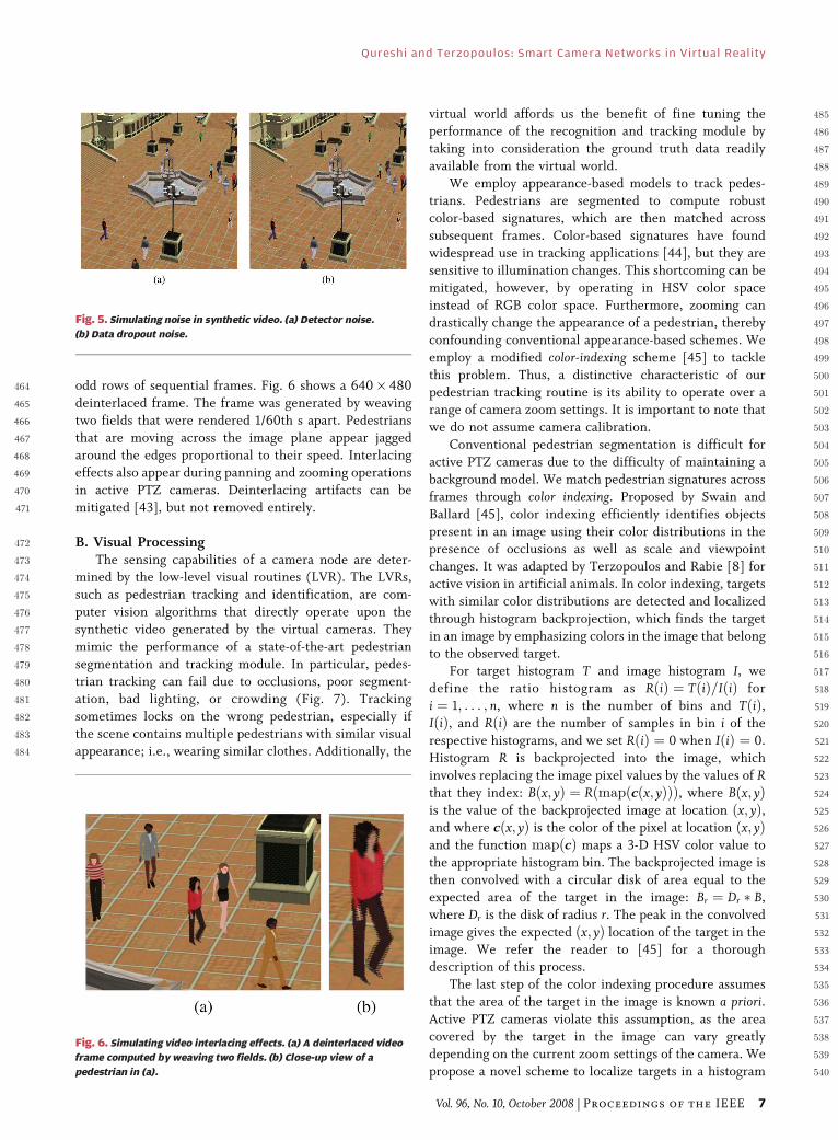
479 segmentation and tracking module. In particular, pedes-
480 trian tracking can fail due to occlusions, poor segment-
481 ation, bad lighting, or crowding (Fig. 7). Tracking482 sometimes locks on the wrong pedestrian, especially if
483 the scene contains multiple pedestrians with similar visual
484 appearance; i.e., wearing similar clothes. Additionally, the
485virtual world affords us the benefit of fine tuning the486performance of the recognition and tracking module by
487taking into consideration the ground truth data readily
488available from the virtual world.
489We employ appearance-based models to track pedes-
490trians. Pedestrians are segmented to compute robust
491color-based signatures, which are then matched across
492subsequent frames. Color-based signatures have found
493widespread use in tracking applications [44], but they are494sensitive to illumination changes. This shortcoming can be
495mitigated, however, by operating in HSV color space
496instead of RGB color space. Furthermore, zooming can
497drastically change the appearance of a pedestrian, thereby
498confounding conventional appearance-based schemes. We
499employ a modified color-indexing scheme [45] to tackle
500this problem. Thus, a distinctive characteristic of our
501pedestrian tracking routine is its ability to operate over a502range of camera zoom settings. It is important to note that
503we do not assume camera calibration.
504Conventional pedestrian segmentation is difficult for
505active PTZ cameras due to the difficulty of maintaining a
506background model. We match pedestrian signatures across
507frames through color indexing. Proposed by Swain and
508Ballard [45], color indexing efficiently identifies objects
509present in an image using their color distributions in the510presence of occlusions as well as scale and viewpoint
511changes. It was adapted by Terzopoulos and Rabie [8] for
512active vision in artificial animals. In color indexing, targets
513with similar color distributions are detected and localized
514through histogram backprojection, which finds the target
515in an image by emphasizing colors in the image that belong
516to the observed target.
517For target histogram T and image histogram I, we518define the ratio histogram as RðiÞ ¼ TðiÞ=IðiÞ for
519i ¼ 1; . . . ; n, where n is the number of bins and TðiÞ,520IðiÞ, and RðiÞ are the number of samples in bin i of the
521respective histograms, and we set RðiÞ ¼ 0 when IðiÞ ¼ 0.
522Histogram R is backprojected into the image, which
523involves replacing the image pixel values by the values of R524that they index: Bðx; yÞ ¼ Rðmapðcðx; yÞÞÞ, where Bðx; yÞ525is the value of the backprojected image at location ðx; yÞ,526and where cðx; yÞ is the color of the pixel at location ðx; yÞ527and the function mapðcÞ maps a 3-D HSV color value to
528the appropriate histogram bin. The backprojected image is
529then convolved with a circular disk of area equal to the
530expected area of the target in the image: Br ¼ Dr � B,
531where Dr is the disk of radius r. The peak in the convolved
532image gives the expected ðx; yÞ location of the target in the
533image. We refer the reader to [45] for a thorough534description of this process.
535The last step of the color indexing procedure assumes
536that the area of the target in the image is known a priori.537Active PTZ cameras violate this assumption, as the area
538covered by the target in the image can vary greatly
539depending on the current zoom settings of the camera. We
540propose a novel scheme to localize targets in a histogram
Fig. 6. Simulating video interlacing effects. (a) A deinterlaced video
frame computed by weaving two fields. (b) Close-up view of a
pedestrian in (a).
Fig. 5. Simulating noise in synthetic video. (a) Detector noise.
(b) Data dropout noise.
Qureshi and Terzopoulos: Smart Camera Networks in Virtual Reality
Vol. 96, No. 10, October 2008 | Proceedings of the IEEE 7
541 backprojected image when the size of the targets in the
542 image is not known beforehand. Our scheme is based on
543 the observation that when the size of the target is equal to544 the size of the localization kernel (i.e., the disk Dr), the
545 filter response forms a peak at the Btrue[ location of the
546 target. On the other hand, the filter response forms a
547 plateau centered at the Btrue[ location of the target in the
548 image for kernel sizes that are either too large or too small
549 relative to the size of the target in the image. Fig. 8 illus-
550 trates this phenomenon. Fig. 9 details and demonstrates
Fig. 8. Multiscale target localization in histogram backprojected
images: Convolving an idealized 7-pixel 1-D backprojected image I with
1-tap, 3-tap, and 5-tap summing kernels. The image is extended with
0 borders for convolution purposes.
Fig. 9. Target localization in backprojected images. The algorithm
is detailed (top) and demonstrated on synthetic data using
ð6l þ 1Þ � ð2l þ 1Þ rectangular summing kernels. (a) An ideal 2-D
backprojected image that contains four different-sized targets.
(b) Noise is added to the image to exacerbate the localization problem.
(c) Our multiscale localization procedure successfully identifies all
four regions, whereas the procedure in [45] yields poor localization
results for kernel sizes 3 (d), 5 (e), and 7 (f).
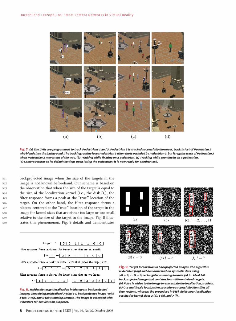
Fig. 7. (a) The LVRs are programmed to track Pedestrians 1 and 3. Pedestrian 3 is tracked successfully; however, track is lost of Pedestrian 1
who blends into the background. The tracking routine loses Pedestrian 3 when she is occluded by Pedestrian 2, but it regains track of Pedestrian 3
when Pedestrian 2 moves out of the way. (b) Tracking while fixating on a pedestrian. (c) Tracking while zooming in on a pedestrian.
(d) Camera returns to its default settings upon losing the pedestrian; it is now ready for another task.
Qureshi and Terzopoulos: Smart Camera Networks in Virtual Reality
8 Proceedings of the IEEE | Vol. 96, No. 10, October 2008
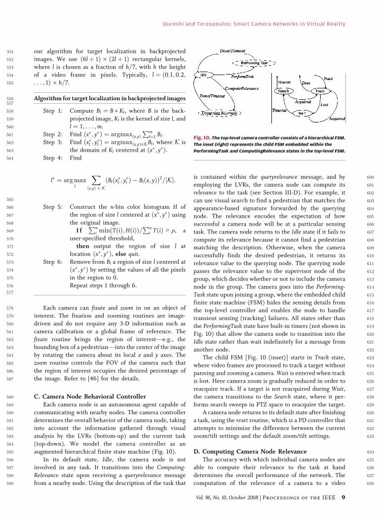
551 our algorithm for target localization in backprojected552 images. We use ð6lþ 1Þ � ð2lþ 1Þ rectangular kernels,
553 where l is chosen as a fraction of h=7, with h the height
554 of a video frame in pixels. Typically, l ¼ ð0:1; 0:2;555 . . . ; 1Þ � h=7.
556 Algorithm for target localization in backprojected images557
558 Step 1: Compute Bl ¼ B � Kl, where B is the back-
559 projected image, Kl is the kernel of size l, and560 l ¼ 1; . . . ;m.
561 Step 2: Find ðx�; y�Þ ¼ argmaxðx;yÞPm
l¼1 Bl.
562 Step 3: Find ðx�l ; y�l Þ ¼ argmaxðx;yÞ2KBl, where K is
563 the domain of Kl centered at ðx�; y�Þ.564 Step 4: Find
l� ¼ arg maxl
Xðx;yÞ 2 K
ðBlðx�l ; y�l Þ � Blðx; yÞÞ2=jKj:
565
566 Step 5: Construct the n-bin color histogram H of
567 the region of size l centered at ðx�; y�Þ using
568 the original image.
569 I fPn
i min TðiÞ;HðiÞð Þ=Pn
i TðiÞ 9 �, a
570 user-specified threshold,571 then output the region of size l at
572 location ðx�; y�Þ, else quit.573 Step 6: Remove from Bl a region of size l centered at
574 ðx�; y�Þ by setting the values of all the pixels
575 in the region to 0.
576 Repeat steps 1 through 6.577
578 Each camera can fixate and zoom in on an object of
579 interest. The fixation and zooming routines are image-
580 driven and do not require any 3-D information such as
581 camera calibration or a global frame of reference. The
582 fixate routine brings the region of interestVe.g., the583 bounding box of a pedestrianVinto the center of the image
584 by rotating the camera about its local x and y axes. The
585 zoom routine controls the FOV of the camera such that
586 the region of interest occupies the desired percentage of
587 the image. Refer to [46] for the details.
588 C. Camera Node Behavioral Controller589 Each camera node is an autonomous agent capable of
590 communicating with nearby nodes. The camera controller
591 determines the overall behavior of the camera node, taking592 into account the information gathered through visual
593 analysis by the LVRs (bottom-up) and the current task
594 (top-down). We model the camera controller as an
595 augmented hierarchical finite state machine (Fig. 10).
596 In its default state, Idle, the camera node is not
597 involved in any task. It transitions into the Computing-598 Relevance state upon receiving a queryrelevance message
599 from a nearby node. Using the description of the task that
600is contained within the queryrelevance message, and by601employing the LVRs, the camera node can compute its
602relevance to the task (see Section III-D). For example, it
603can use visual search to find a pedestrian that matches the
604appearance-based signature forwarded by the querying
605node. The relevance encodes the expectation of how
606successful a camera node will be at a particular sensing
607task. The camera node returns to the Idle state if it fails to
608compute its relevance because it cannot find a pedestrian609matching the description. Otherwise, when the camera
610successfully finds the desired pedestrian, it returns its
611relevance value to the querying node. The querying node
612passes the relevance value to the supervisor node of the
613group, which decides whether or not to include the camera
614node in the group. The camera goes into the Performing-615Task state upon joining a group, where the embedded child
616finite state machine (FSM) hides the sensing details from617the top-level controller and enables the node to handle
618transient sensing (tracking) failures. All states other than
619the PerformingTask state have built-in timers (not shown in
620Fig. 10) that allow the camera node to transition into the
621Idle state rather than wait indefinitely for a message from
622another node.
623The child FSM [Fig. 10 (inset)] starts in Track state,
624where video frames are processed to track a target without625panning and zooming a camera. Wait is entered when track
626is lost. Here camera zoom is gradually reduced in order to
627reacquire track. If a target is not reacquired during Wait,628the camera transitions to the Search state, where it per-
629forms search sweeps in PTZ space to reacquire the target.
630A camera node returns to its default state after finishing
631a task, using the reset routine, which is a PD controller that
632attempts to minimize the difference between the current633zoom/tilt settings and the default zoom/tilt settings.
634D. Computing Camera Node Relevance635The accuracy with which individual camera nodes are
636able to compute their relevance to the task at hand
637determines the overall performance of the network. The
638computation of the relevance of a camera to a video
Fig. 10. The top-level camera controller consists of a hierarchical FSM.
The inset (right) represents the child FSM embedded within the
PerformingTask and ComputingRelevance states in the top-level FSM.
Qureshi and Terzopoulos: Smart Camera Networks in Virtual Reality
Vol. 96, No. 10, October 2008 | Proceedings of the IEEE 9
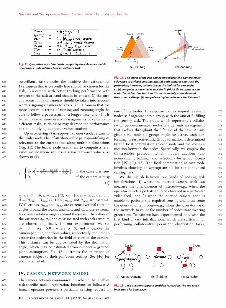
639 surveillance task encodes the intuitive observations that
640 1) a camera that is currently free should be chosen for the
641 task, 2) a camera with better tracking performance with
642 respect to the task at hand should be chosen, 3) the turn
643 and zoom limits of cameras should be taken into account
644 when assigning a camera to a task; i.e., a camera that has645 more leeway in terms of turning and zooming might be
646 able to follow a pedestrian for a longer time, and 4) it is
647 better to avoid unnecessary reassignments of cameras to
648 different tasks, as doing so may degrade the performance
649 of the underlying computer vision routines.
650 Upon receiving a task request, a camera node returns to
651 the leader node a list of attribute-value pairs quantifying its
652 relevance to the current task along multiple dimensions653 (Fig. 11). The leader node uses them to compute a rele-
654 vance metric whose result is a scalar relevance value r, as
655 shown in (1),
r¼ exp � ð���Þ2
2��2 �ð���Þ2
2��2 �ð���Þ2
2��2
� �; if the camera is free
0; if the camera is busy
(
(1)
656 where � ¼ ð�min þ �maxÞ=2, � ¼ ð�min þ �maxÞ=2, and
657 � ¼ ð�min þ �maxÞ=2. Here, �min and �max are extremal
658 FOV settings, �min and �max are extremal vertical rotation659 angles around the x-axis, and �min and �max are extremal
660 horizontal rotation angles around the y-axis. The values of
661 the variances ��, ��, and �� associated with each attribute
662 are chosen empirically (in our experiments, we set
663 �� ¼ �� ¼ �� ¼ 5:0), where �, �, and � denote the
664 camera pan, tilt, and zoom values, respectively, required to
665 center the pedestrian in the field of view of the camera.
666 This distance can be approximated by the declination667 angle, which may be estimated from � under a ground-
668 plane assumption. Fig. 12 illustrates the relevance of
669 cameras subject to their pan/zoom settings. See [46] for
670 additional details.
671 IV. CAMERA NETWORK MODEL
672 The camera network communication scheme that enables673 task-specific node organization functions as follows: A
674 human operator presents a particular sensing request to
675one of the nodes. In response to this request, relevant
676nodes self-organize into a group with the aim of fulfilling
677the sensing task. The group, which represents a collabo-
678ration between member nodes, is a dynamic arrangement
679that evolves throughout the lifetime of the task. At any
680given time, multiple groups might be active, each per-
681forming its respective task. Group formation is determined
682by the local computation at each node and the commu-683nication between the nodes. Specifically, we employ the
684ContractNet protocol, which models auctions (an-
685nouncement, bidding, and selection) for group forma-
686tion [35] (Fig. 13). The local computation at each node
687involves choosing an appropriate bid for the announced
688sensing task.
689We distinguish between two kinds of sensing task
690initializations: 1) where the queried camera itself can691measure the phenomenon of interestVe.g., when the
692operator selects a pedestrian to be observed in a particular
693video feedVand 2) when the queried camera node is
694unable to perform the required sensing and must route
695the query to other nodesVe.g., when the operator tasks
696the network to count the number of pedestrians wearing
697green tops. To date we have experimented only with the
698first kind of task initializations, which are sufficient for699performing collaborative persistent observation tasks;
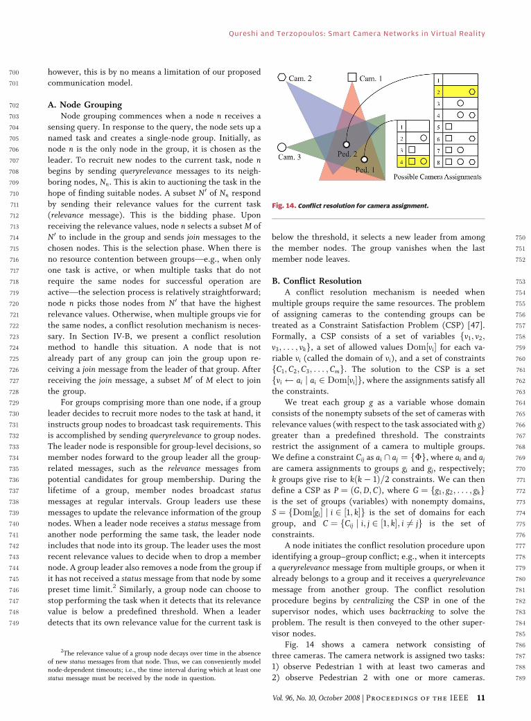
Fig. 11. Quantities associated with computing the relevance metric
of a camera node relative to a surveillance task.
Fig. 12. The effect of the pan and zoom settings of a camera on its
relevance to a visual sensing task. (a) Both cameras can track the
pedestrian; however, Camera 2 is at the limit of its pan angle,
so (1) computes a lower relevance for it. (b) All three cameras can
track the pedestrian, but 2 and 3 can do so only at the limits of
their zoom settings; (1) computes a higher relevance for Camera 1.
Fig. 13. Task auction supports coalition formation. The red cross
indicates a lost message.
Qureshi and Terzopoulos: Smart Camera Networks in Virtual Reality
10 Proceedings of the IEEE | Vol. 96, No. 10, October 2008
700 however, this is by no means a limitation of our proposed701 communication model.
702 A. Node Grouping703 Node grouping commences when a node n receives a
704 sensing query. In response to the query, the node sets up a
705 named task and creates a single-node group. Initially, as
706 node n is the only node in the group, it is chosen as the
707 leader. To recruit new nodes to the current task, node n708 begins by sending queryrelevance messages to its neigh-
709 boring nodes, Nn. This is akin to auctioning the task in the
710 hope of finding suitable nodes. A subset N0 of Nn respond
711 by sending their relevance values for the current task
712 (relevance message). This is the bidding phase. Upon
713 receiving the relevance values, node n selects a subset M of
714 N0 to include in the group and sends join messages to the
715 chosen nodes. This is the selection phase. When there is716 no resource contention between groupsVe.g., when only
717 one task is active, or when multiple tasks that do not
718 require the same nodes for successful operation are
719 activeVthe selection process is relatively straightforward;
720 node n picks those nodes from N0 that have the highest
721 relevance values. Otherwise, when multiple groups vie for
722 the same nodes, a conflict resolution mechanism is neces-
723 sary. In Section IV-B, we present a conflict resolution724 method to handle this situation. A node that is not
725 already part of any group can join the group upon re-
726 ceiving a join message from the leader of that group. After
727 receiving the join message, a subset M0 of M elect to join
728 the group.
729 For groups comprising more than one node, if a group
730 leader decides to recruit more nodes to the task at hand, it
731 instructs group nodes to broadcast task requirements. This732 is accomplished by sending queryrelevance to group nodes.
733 The leader node is responsible for group-level decisions, so
734 member nodes forward to the group leader all the group-
735 related messages, such as the relevance messages from
736 potential candidates for group membership. During the
737 lifetime of a group, member nodes broadcast status738 messages at regular intervals. Group leaders use these
739 messages to update the relevance information of the group740 nodes. When a leader node receives a status message from
741 another node performing the same task, the leader node
742 includes that node into its group. The leader uses the most
743 recent relevance values to decide when to drop a member
744 node. A group leader also removes a node from the group if
745 it has not received a status message from that node by some
746 preset time limit.2 Similarly, a group node can choose to
747 stop performing the task when it detects that its relevance748 value is below a predefined threshold. When a leader
749 detects that its own relevance value for the current task is
750below the threshold, it selects a new leader from among
751the member nodes. The group vanishes when the last752member node leaves.
753B. Conflict Resolution754A conflict resolution mechanism is needed when
755multiple groups require the same resources. The problem
756of assigning cameras to the contending groups can be
757treated as a Constraint Satisfaction Problem (CSP) [47].
758Formally, a CSP consists of a set of variables fv1; v2;759v3; . . . ; vkg, a set of allowed values Dom½vi� for each va-
760riable vi (called the domain of vi), and a set of constraints
761fC1; C2; C3; . . . ; Cmg. The solution to the CSP is a set
762fvi ai j ai 2 Dom½vi�g, where the assignments satisfy all
763the constraints.
764We treat each group g as a variable whose domain
765consists of the nonempty subsets of the set of cameras with
766relevance values (with respect to the task associated with g)767greater than a predefined threshold. The constraints
768restrict the assignment of a camera to multiple groups.
769We define a constraint Cij as ai \ aj ¼ f�g, where ai and aj
770are camera assignments to groups gi and gj, respectively;
771k groups give rise to kðk� 1Þ=2 constraints. We can then
772define a CSP as P ¼ ðG;D; CÞ, where G ¼ fg1; g2; . . . ; gkg773is the set of groups (variables) with nonempty domains,
774S ¼ fDom½gi� j i 2 ½1; k�g is the set of domains for each775group, and C ¼ fCij j i; j 2 ½1; k�; i 6¼ jg is the set of
776constraints.
777A node initiates the conflict resolution procedure upon
778identifying a group–group conflict; e.g., when it intercepts
779a queryrelevance message from multiple groups, or when it
780already belongs to a group and it receives a queryrelevance781message from another group. The conflict resolution
782procedure begins by centralizing the CSP in one of the783supervisor nodes, which uses backtracking to solve the
784problem. The result is then conveyed to the other super-
785visor nodes.
786Fig. 14 shows a camera network consisting of
787three cameras. The camera network is assigned two tasks:
7881) observe Pedestrian 1 with at least two cameras and
7892) observe Pedestrian 2 with one or more cameras.
2The relevance value of a group node decays over time in the absenceof new status messages from that node. Thus, we can conveniently modelnode-dependent timeouts; i.e., the time interval during which at least onestatus message must be received by the node in question.
Fig. 14. Conflict resolution for camera assignment.
Qureshi and Terzopoulos: Smart Camera Networks in Virtual Reality
Vol. 96, No. 10, October 2008 | Proceedings of the IEEE 11
790 Pedestrian 1 is visible in Cameras 1 and 3, and Pedestrian 2791 is visible in all three cameras. Treating each task (or group)
792 as a variable, we cast camera assignment as a CSP. The
793 valid camera assignments listed in Fig. 14 define the
794 domain of the two variables. The domain of each task (or
795 group) is the powerset of the set of cameras that can carry
796 out the task (i.e., that can be a member of the corre-
797 sponding group). Since each camera can carry out only one
798 task (or be a member of only one group) at any given time,799 a valid camera assignment will not assign any camera to
800 more than one task (group). We express this restriction as
801 a binary constraint by enforcing the intersection of the set
802 of cameras assigned to any two tasks to be the null set. In
803 the above scenario, Cameras 1 and 3 are assigned to
804 Pedestrian 1 and Camera 2 is assigned to Pedestrian 2
805 (highlighted rows in Fig. 14).
806 CSPs have been studied extensively in the computer807 science literature and there exist several methods for
808 solving them. We employ backtracking to search system-
809 atically through the space of possibilities in order to find an
810 optimal camera assignment. The naive backtracking
811 method, which we denote AllSolv, enumerates every
812 solution in order to find the best solution. Instead, we
813 store the currently best result and backtrack whenever the
814 current partial solution is of poorer quality. We call this815 method BestSolv. Using this strategy, we can guarantee an
816 optimal solution under the assumption that the quality of
817 solutions increase monotonically as values are assigned to
818 more variables. When P does not have a solution, we solve
819 smaller CSPs by relaxing the node requirements for
820 each task.
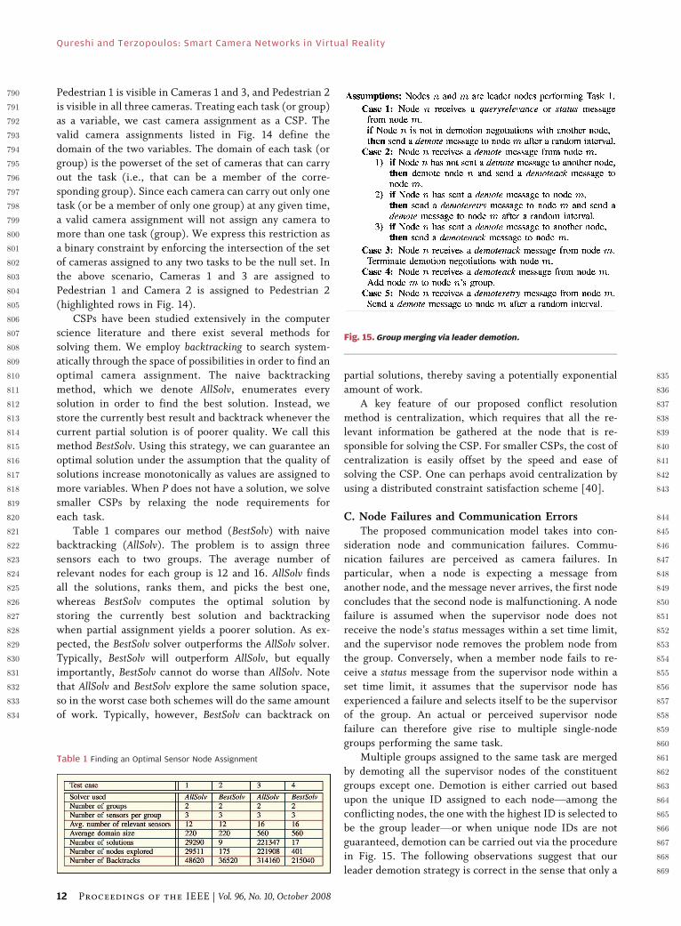
821 Table 1 compares our method (BestSolv) with naive
822 backtracking (AllSolv). The problem is to assign three823 sensors each to two groups. The average number of
824 relevant nodes for each group is 12 and 16. AllSolv finds
825 all the solutions, ranks them, and picks the best one,
826 whereas BestSolv computes the optimal solution by
827 storing the currently best solution and backtracking
828 when partial assignment yields a poorer solution. As ex-
829 pected, the BestSolv solver outperforms the AllSolv solver.
830 Typically, BestSolv will outperform AllSolv, but equally831 importantly, BestSolv cannot do worse than AllSolv. Note
832 that AllSolv and BestSolv explore the same solution space,
833 so in the worst case both schemes will do the same amount
834 of work. Typically, however, BestSolv can backtrack on
835partial solutions, thereby saving a potentially exponential
836amount of work.
837A key feature of our proposed conflict resolution
838method is centralization, which requires that all the re-
839levant information be gathered at the node that is re-840sponsible for solving the CSP. For smaller CSPs, the cost of
841centralization is easily offset by the speed and ease of
842solving the CSP. One can perhaps avoid centralization by
843using a distributed constraint satisfaction scheme [40].
844C. Node Failures and Communication Errors845The proposed communication model takes into con-
846sideration node and communication failures. Commu-847nication failures are perceived as camera failures. In
848particular, when a node is expecting a message from
849another node, and the message never arrives, the first node
850concludes that the second node is malfunctioning. A node
851failure is assumed when the supervisor node does not
852receive the node’s status messages within a set time limit,
853and the supervisor node removes the problem node from
854the group. Conversely, when a member node fails to re-855ceive a status message from the supervisor node within a
856set time limit, it assumes that the supervisor node has
857experienced a failure and selects itself to be the supervisor
858of the group. An actual or perceived supervisor node
859failure can therefore give rise to multiple single-node
860groups performing the same task.
861Multiple groups assigned to the same task are merged
862by demoting all the supervisor nodes of the constituent863groups except one. Demotion is either carried out based
864upon the unique ID assigned to each nodeVamong the
865conflicting nodes, the one with the highest ID is selected to
866be the group leaderVor when unique node IDs are not
867guaranteed, demotion can be carried out via the procedure
868in Fig. 15. The following observations suggest that our
869leader demotion strategy is correct in the sense that only a
Table 1 Finding an Optimal Sensor Node Assignment
Fig. 15. Group merging via leader demotion.
Qureshi and Terzopoulos: Smart Camera Networks in Virtual Reality
12 Proceedings of the IEEE | Vol. 96, No. 10, October 2008
870 single leader node survives the demotion negotiations and871 every other leader node is demoted: 1) The demotion
872 process for more than two nodes involves repeated
873 (distributed and parallel) application of the demotion
874 process between two nodes. 2) The demotion process
875 between two leader nodes either succeeds or fails. It
876 succeeds when one of the two nodes is demoted. Demotion
877 between two nodes is based on the contention manage-
878 ment scheme that was first introduced in the ALOHA879 network protocol [48], which was developed in the late
880 1960s and was a precursor to the ubiquitous Ethernet
881 protocol (see [49] for the details). In its basic version, the
882 ALOHA protocol states the following.
883 • If you have data to send, send it.
884 • If there is a collision, resend after a random
885 interval.
886 The important thing to note here is that the demotion887 process between two nodes will eventually succeed and
888 one of the two leader nodes will be demoted.
889 V. PERSISTENT SURVEILLANCE
890 Consider how a network of smart cameras may be used in
891 the context of video surveillance (Fig. 16). Any two
892 camera nodes that are within communication range of893 each other are considered neighbors. A direct conse-
894 quence of this approach is that the network can easily be
895 modified through removal, addition, or replacement of
896 camera nodes.
897 A human operator spots one or more mobile pedes-
898 trians of interest in a video feed and, for example, requests
899 the network to Bzoom in on this pedestrian,[ Bobserve this
900 pedestrian,[ or Bobserve the entire group.[ The successful901 execution and completion of these tasks requires an
902 intelligent allocation of the available cameras. In par-
903 ticular, the network must decide which cameras should
904 track the pedestrian and for how long.
905The accuracy with which individual camera nodes are
906able to compute their relevance to the task at hand
907determines the overall performance of the network (see
908Section III-D and [46] for the details). The computed
909relevance values are used by the node selection scheme910described above to assign cameras to various tasks. The
911supervisor node gives preference to the nodes that are
912currently free, so the nodes that are part of another group
913are selected only when an insufficient number of free
914nodes are available for the current task.
915A detailed world model that includes the location of
916cameras, their fields of view, pedestrian motion prediction
Fig. 16. A camera network for video surveillance consists of camera
nodes that can communicate with other nearby nodes. Collaborative,
persistent surveillance requires that cameras organize themselves to
perform camera handover when the observed subject moves out of
the sensing range of one camera and into that of another.
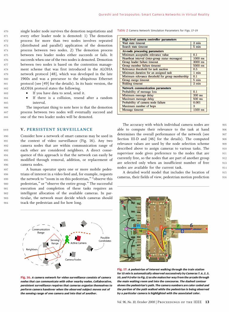
Table 2 Camera Network Simulation Parameters for Figs. 17–19
Fig. 17. A pedestrian of interest walking through the train station
for 15 min is automatically observed successively by Cameras 7, 6, 2, 3,
10, and 9 (refer to Fig. 1) as she makes her way from the arcade through
the main waiting room and into the concourse. The dashed contour
shows the pedestrian’s path. The camera numbers are color coded and
the portion of the path walked while the pedestrian is being observed
by a particular camera is highlighted with the associated color.
Qureshi and Terzopoulos: Smart Camera Networks in Virtual Reality
Vol. 96, No. 10, October 2008 | Proceedings of the IEEE 13
917 models, occlusion models, and pedestrian movement918 pathways may allow (in some sense) optimal allocation
919 of camera resources; however, it is cumbersome and in
920 most cases infeasible to acquire such a world model. Our
921 approach eschews such detailed knowledge. We assume
922 only that a pedestrian can be identified with reasonable
923 accuracy by the camera nodes.
924 A. Results925 To date, we have simulated our smart camera network
926 with up to 16 stationary and/or PTZ virtual cameras in the
927 virtual train station populated with up to 100 autonomous
928 pedestrians, with network simulation parameters per Table 2.
929 For the 15-min simulation illustrated in Figs. 17 and 18,
930 with 16 active PTZ cameras in the train station as indicated
931in Fig. 1, an operator selects the female pedestrian with the932red top visible in Camera 7 [Fig. 18(e)] and initiates an
933observe task. Camera 7 forms a task group and begins
934tracking the pedestrian. Subsequently, Camera 7 recruits
935Camera 6, which in turn recruits Cameras 2 and 3 to
936observe the pedestrian. Camera 6 becomes the supervisor
937of the group when Camera 7 loses track of the pedestrian
938and leaves the group. Subsequently, Camera 6 experiences
939a tracking failure, sets Camera 3 as the group supervisor,940and leaves the group. Cameras 2 and 3 persistently observe
941the pedestrian during her stay in the main waiting room,
942where she also visits a vending machine. When the
943pedestrian enters the portal connecting the main waiting
944room to the concourse, Cameras 10 and 11 are recruited
945and they take over the group from Cameras 2 and 3.
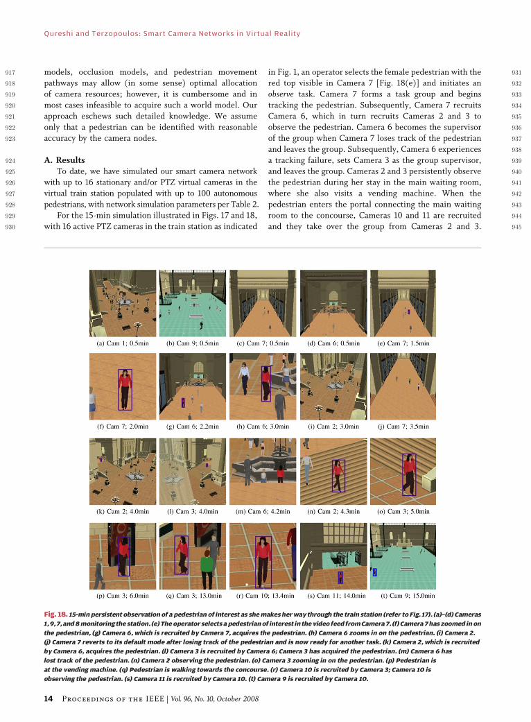
Fig. 18. 15-min persistent observation of a pedestrian of interest as she makes her way through the train station (refer to Fig. 17). (a)–(d) Cameras
1, 9, 7, and 8 monitoring the station. (e) The operator selects a pedestrian of interest in the video feed from Camera 7. (f) Camera 7 has zoomed in on
the pedestrian, (g) Camera 6, which is recruited by Camera 7, acquires the pedestrian. (h) Camera 6 zooms in on the pedestrian. (i) Camera 2.
(j) Camera 7 reverts to its default mode after losing track of the pedestrian and is now ready for another task. (k) Camera 2, which is recruited
by Camera 6, acquires the pedestrian. (l) Camera 3 is recruited by Camera 6; Camera 3 has acquired the pedestrian. (m) Camera 6 has
lost track of the pedestrian. (n) Camera 2 observing the pedestrian. (o) Camera 3 zooming in on the pedestrian. (p) Pedestrian is
at the vending machine. (q) Pedestrian is walking towards the concourse. (r) Camera 10 is recruited by Camera 3; Camera 10 is
observing the pedestrian. (s) Camera 11 is recruited by Camera 10. (t) Camera 9 is recruited by Camera 10.
Qureshi and Terzopoulos: Smart Camera Networks in Virtual Reality
14 Proceedings of the IEEE | Vol. 96, No. 10, October 2008
946 Cameras 2 and 3 leave the group and return to their default
947 states. Later, Camera 11, which is now acting as the group’s
948 supervisor, recruits Camera 9, which observes the pedes-
949 trian as she enters the concourse.
950 Fig. 19 illustrates camera assignment and conflict951 resolution. First, Cameras 1 and 2 situated in the main
952 waiting room successfully form a group to observe the first
953 pedestrian that enters the scene, and there is only one
954 active task. When the user specifies a second taskVfollow
955 the pedestrian wearing the green topVthe cameras decide
956 to break the group and reassign themselves. They decide
957 among themselves that Camera 1 is more suitable for
958 observing the pedestrian in the green top. Camera 2959 continues observing the first pedestrian that entered the
960 scene. Note that the cameras are able to handle the two
961 observation tasks completely autonomously and also that
962 the interaction between them is strictly localVthe other
963 14 cameras present in the network (Fig. 1) are not involved.
964 We have observed that the camera network correctly
965 assigns cameras in most cases. The problems that we
966 encountered are usually related to pedestrian identification967 and tracking. The task of persistently observing a
968 pedestrian moving through an extensive space will fail if
969 the low-level visual analysis routines cannot correctly
970 identify the pedestrian from camera to camera. As we
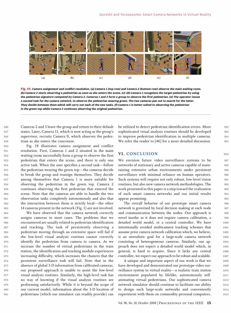
971 increase the number of virtual pedestrians in the train
972 station, the identification and tracking module experiences
973 increasing difficulty, which increases the chances that the
974 persistent surveillance task will fail. Note that in the975 absence of global 3-D information from calibrated cameras,
976 our proposed approach is unable to assist the low-level
977 visual analysis routines. Similarly, the high-level task has
978 no way of knowing if the visual analysis routines are
979 performing satisfactorily. While it is beyond the scope of
980 our current model, information about the 3-D location of
981 pedestrians (which our simulator can readily provide) can
982be utilized to detect pedestrian identification errors. More
983sophisticated visual analysis routines should be developed
984to improve pedestrian identification in multiple cameras.
985We refer the reader to [46] for a more detailed discussion.
986VI. CONCLUSION
987We envision future video surveillance systems to be
988networks of stationary and active cameras capable of main-
989taining extensive urban environments under persistent
990surveillance with minimal reliance on human operators.
991Such systems will require not only robust, low-level vision
992routines, but also new camera network methodologies. The993work presented in this paper is a step toward the realization
994of such smart camera networks and our initial results
995appear promising.
996The overall behavior of our prototype smart camera
997network is governed by local decision making at each node
998and communication between the nodes. Our approach is
999novel insofar as it does not require camera calibration, a
1000detailed world model, or a central controller. We have1001intentionally avoided multicamera tracking schemes that
1002assume prior camera network calibration which, we believe,
1003is an unrealistic goal for a large-scale camera network
1004consisting of heterogeneous cameras. Similarly, our ap-
1005proach does not expect a detailed world model which, in
1006general, is hard to acquire. Since it lacks any central
1007controller, we expect our approach to be robust and scalable.
1008A unique and important aspect of our work is that we1009have developed and demonstrated our prototype video sur-
1010veillance system in virtual realityVa realistic train station
1011environment populated by lifelike, autonomously self-
1012animating virtual pedestrians. Our sophisticated camera
1013network simulator should continue to facilitate our ability
1014to design such large-scale networks and conveniently
1015experiment with them on commodity personal computers.
Fig. 19. Camera assignment and conflict resolution. (a) Camera 1 (top row) and Camera 2 (bottom row) observe the main waiting room.
(b) Camera 2 starts observing a pedestrian as soon as she enters the scene. (c)–(d) Camera 1 recognizes the target pedestrian by using
the pedestrian signature computed by Camera 2. Cameras 1 and 2 form a group to observe the first pedestrian. (e) The operator issues
a second task for the camera network, to observe the pedestrian wearing green. The two cameras pan out to search for the latter.
They decide between them which will carry out each of the two tasks. (f) Camera 1 is better suited to observing the pedestrian
in the green top while Camera 2 continues observing the original pedestrian.
Qureshi and Terzopoulos: Smart Camera Networks in Virtual Reality
Vol. 96, No. 10, October 2008 | Proceedings of the IEEE 15
1016 We are currently experimenting with more elaborate
1017 scenarios involving multiple cameras situated in different
1018 locations within the train station, with which we would
1019 like to study the performance of the network in per-
1020 sistently observing multiple pedestrians during their
1021 extended presence in the train station. h
1022Acknowledgment
1023The authors wish to thank W. Shao for develop-
1024ing and implementing the train station simulator and1025M. Plaza-Villegas for his valuable contributions. They also
1026wish to thank T. Strat, formerly of DARPA, for his
1027generous support and encouragement.
REF ERENCE S
[1] W. Shao and D. Terzopoulos, BAutonomouspedestrians,[ Graph. Models, vol. 69, no. 5–6,pp. 246–274, Sep./Nov. 2007.
[2] W. H. Widen, BSmart cameras and the rightto privacy,[ Proc. IEEE, vol. 96, no. 10,Oct. 2008.
[3] C. J. Costello, C. P. Diehl, A. Banerjee, andH. Fisher, BScheduling an active camera toobserve people,[ in Proc. ACM Int. Workshopon Video Surveillance and Sensor Networks,New York, 2004, pp. 39–45.
[4] F. Zhao, J. Liu, J. Liu, L. Guibas, and J. Reich,BCollaborative signal and informationprocessing: An information directedapproach,[ Proc. IEEE, vol. 91, no. 8,pp. 1199–1209, Aug. 2003.
[5] C. Intanagonwiwat, R. Govindan, D. Estrin,J. Heidemann, and F. Silva, BDirecteddiffusion for wireless sensor networking,[IEEE/ACM Trans. Netw., vol. 11, no. 1,pp. 2–16, Feb. 2003.
[6] F. Qureshi and D. Terzopoulos, BVirtualvision and smart cameras,[ in Proc. 1stACM/IEEE Int. Conf. Distributed SmartCameras, Vienna, Austria, Sep. 2007,pp. 87–94.
[7] F. Qureshi and D. Terzopoulos,BSurveillance camera scheduling: A virtualvision approach,[ ACM Multimedia Syst. J.,vol. 12, pp. 269–283, Dec. 2006.
[8] D. Terzopoulos and T. Rabie, BAnimat vision:Active vision in artificial animals,[ Videre:J. Comp. Vision Res., vol. 1, no. 1, pp. 2–19,Sep. 1997.
[9] T. Rabie and D. Terzopoulos, BActiveperception in virtual humans,[ in VisionInterface, Montreal, QC, Canada, May 2000,pp. 16–22.
[10] T. Rabie, A. Shalaby, B. Abdulhai, andA. El-Rabbany, BMobile vision-basedvehicle tracking and traffic control,[ inProc. IEEE Int. Conf. Intelligent TransportationSystems, Singapore, Sep. 2002, pp. 13–18.
[11] D. Terzopoulos, BPerceptive agents andsystems in virtual reality,[ in Proc. ACMSymp. Virtual Reality Software and Technology,Osaka, Japan, Oct. 2003, pp. 1–3.
[12] A. Santuari, O. Lanz, and R. Brunelli,BSynthetic movies for computer visionapplications,[ in Proc. IASTED Int. Conf.Visualization, Imaging, and Image Processing,pp. 1–6.
[13] F. Bertamini, R. Brunelli, O. Lanz, A. Roat,A. Santuari, F. Tobia, and Q. Xu, BOlympus:An ambient intelligence architecture on theverge of reality,[ in Proc. Int. Conf. ImageAnalysis and Processing, Mantova, Italy,Sep. 2003, pp. 139–145.
[14] R. Collins, O. Amidi, and T. Kanade,BAn active camera system for acquiringmulti-view video,[ in Proc. Int. Conf.Image Processing, Rochester, NY,Sep. 2002, pp. 517–520.
[15] D. Comaniciu, F. Berton, and V. Ramesh,BAdaptive resolution system for distributedsurveillance,[ Real Time Imag., vol. 8, no. 5,pp. 427–437, Oct. 2002.
[16] M. Trivedi, K. Huang, and I. Mikic,BIntelligent environments and activecamera networks,[ in Proc. IEEE Int. Conf.Systems, Man and Cybernetics, Nashville,TN, Oct. 2000, vol. 2, pp. 804–809.
[17] S. Stillman, R. Tanawongsuwan, and I. Essa,BA System for Tracking and RecognizingMultiple People With Multiple Cameras,[Georgia Institute of Technology, GVU Center,1998, Tech. Rep. GIT-GVU-98-25.
[18] O. Javed, Z. Rasheed, O. Alatas, and M. Shah,BKnight: A real time surveillance systemfor multiple and non-overlapping cameras,[in Proc. Int. Conf. Multimedia and Expo,Baltimore, MD, Jul. 2003, vol. 1,pp. 649–652.
[19] S. Khan and M. Shah, BConsistent labelingof tracked objects in multiple cameraswith overlapping fields of view,[ IEEETrans. Pattern Anal. Machine Intell.,vol. 25, no. 10, pp. 1355–1360, Oct. 2003.
[20] J. Kang, I. Cohen, and G. Medioni,BMulti-view tracking within andacross uncalibrated camera streams,[ inProc. ACM SIGMM Int. Workshop on VideoSurveillance, New York, 2003, pp. 21–33.
[21] N. T. Siebel, BDesigning and implementingpeople tracking applications for automatedvisual surveillance,[ Ph.D. dissertation,Dept. Comp. Sci., Univ. Reading, Reading,U.K., 2003.
[22] F. Pedersini, A. Sarti, and S. Tubaro,BAccurate and simple geometric calibrationof multi-camera systems,[ Signal Process.,vol. 77, no. 3, pp. 309–334, 1999.
[23] T. Gandhi and M. M. Trivedi, BCalibrationof a reconfigurable array of omnidirectionalcameras using a moving person,[ in Proc.ACM Int. Workshop on Video Surveillanceand Sensor Networks, New York, , 2004,pp. 12–19.
[24] D. Devarajan, R. J. Radke, and H. Chung,BDistributed metric calibration of ad hoccamera networks,[ ACM Trans. SensorNetw., vol. 2, no. 3, pp. 380–403, 2006.
[25] A. Ihler, J. Fisher, R. Moses, and A. Willsky,BNonparametric belief propagation forself-calibration in sensor networks,[ in Proc.Int. Symp. Information Processing in SensorNetworks, Berkeley, CA, Apr. 2004,pp. 225–233.
[26] D. Marinakis, G. Dudek, and D. Fleet,BLearning sensor network topologythrough Monte Carlo expectationmaximization,[ in Proc. IEEE Intl. Conf.Robotics and Automation, Barcelona, Spain,Apr. 2005, pp. 4581–4587.
[27] J. Mallett, BThe role of groups in smartcamera networks,[ Ph.D. dissertation,Program of Media Arts and Sciences,School of Architecture, MIT, Cambridge,MA, 2006.
[28] R. Collins, A. Lipton, H. Fujiyoshi, andT. Kanade, BAlgorithms for cooperativemultisensor surveillance,[ Proc. IEEE,vol. 89, no. 10, pp. 1456–1477, Oct. 2001.
[29] X. Zhou, R. T. Collins, T. Kanade, andP. Metes, BA master–slave system to
acquire biometric imagery of humansat distance,[ in Proc. ACM SIGMM Inte.Workshop on Video Surveillance, New York,2003, pp. 113–120.
[30] A. Hampapur, S. Pankanti, A. Senior,Y.-L. Tian, L. Brown, and R. Bolle,BFace cataloger: Multi-scale imaging forrelating identity to location,[ in Proc.IEEE Conf. Advanced Video and SignalBased Surveillance, Washington, DC,2003, pp. 13–21.
[31] F. Zhao, J. Shin, and J. Reich,BInformation-driven dynamic sensorcollaboration for tracking applications,[IEEE Signal Process. Mag., vol. 19, pp. 61–72,Mar. 2002.
[32] M. Bhardwaj, A. Chandrakasan, andT. Garnett, BUpper bounds on the lifetimeof sensor networks,[ in Proc. IEEE Int.Conf. Communications, 2001, pp. 785–790.
[33] J. Campbell, P. B. Gibbons, S. Nath,P. Pillai, S. Seshan, and R. Sukthankar,BIrisnet: An internet-scale architecturefor multimedia sensors,[ in Proc. ACM Int.Conf. Multimedia, New York, 2005, pp. 81–88.
[34] P. Kulkarni, D. Ganesan, P. Shenoy, andQ. Lu, BSenseye: A multi-tier camera sensornetwork,[ in Proc. ACM Int. Conf. Multimedia,New York, 2005, pp. 229–238.
[35] R. G. Smith, BThe contract net protocol:High-level communication and controlin a distributed problem solver,[ IEEE Trans.Comput., vol. C-29, no. 12, pp. 1104–1113,Dec. 1980.
[36] B. Gerkey and M. Mataric, BA formalanalysis and taxonomy of task allocationin multi-robot systems,[ Int. J. RoboticsRes., vol. 23, no. 9, pp. 939–954, 2004.
[37] M. R. Garey and D. S. Johnson, BStrongNP-completeness results: Motivation,examples, and implications,[ J. ACM,vol. 25, no. 3, pp. 499–508, 1978.
[38] A. Atamturk, G. Nemhauser, andM. Savelsbergh, BA combined lagrangian,linear programming and implicationheuristic for large-scale set partitioningproblems,[ J. Heuristics, vol. 1, pp. 247–259,1995.
[39] P. J. Modi, W.-S. Shen, M. Tambe, andM. Yokoo, BAdopt: Asynchronous distributedconstraint optimization with qualityguarantees,[ Artificial Intell., vol. 161, no. 1–2,pp. 149–180, Mar. 2006.
[40] M. Yokoo, Distributed Constraint Satisfaction:Foundations of Cooperation in Multi-agentSystems. Berlin, Germany: Springer-Verlag,2001.
[41] J. D. Foley, A. van Dam, S. Feiner, andJ. K. Hughes, Computer Graphics: Principlesand Practice. Boston, MA: Addison-Wesley,1990.
[42] F. Birren, Color Perception in Art..New York: Van Nostrand Reinhold, 1976.
[43] G. D. Haan and E. B. Bellers,BDeinterlacingVAn overview,[ Proc. IEEE,vol. 86, no. 9, pp. 1839–1857, Sep. 1998.
[44] D. Comaniciu, V. Ramesh, and P. Meer,BReal-time tracking of non-rigid objects
Qureshi and Terzopoulos: Smart Camera Networks in Virtual Reality
16 Proceedings of the IEEE | Vol. 96, No. 10, October 2008
using mean shift,[ in Proc. IEEE Conf.Computer Vision and Pattern Recognition,Hilton Head Island, SC, Jun. 2000, vol. 2,pp. 142–151.
[45] M. J. Swain and D. H. Ballard, BColorindexing,[ Int. J. Comp. Vision, vol. 7, no. 1,pp. 11–32, Nov. 1991.
[46] F. Z. Qureshi, BIntelligent perception invirtual camera networks and space robotics,[
Ph.D. dissertation, Dept. Comp. Science,Univ. Toronto, Toronto, ON, Canada,2007.
[47] J. K. Pearson and P. G. Jeavons, BA Surveyof Tractable Constraint SatisfactionProblems,[ University of London, RoyalHolloway, 1997, Tech. Rep. CSD-TR-97-15.
[48] F. F. Kuo, BThe ALOHA system,[ ACMSIGCOMM Computer Commun. Revi., vol. 25,no. 1, pp. 41–44, 1995.
[49] C. Murthy and B. Manoj, Ad Hoc WirelessNetworks Architectures and Protocols.Upper Saddle River, NJ: Prentice-Hall,2004.
ABOUT T HE AUTHO RS
1028 Faisal Qureshi (Member, IEEE) received the B.Sc.
1029 degree in Mathematics and Physics from Punjab
1030 University, Lahore, Pakistan, in 1993, the M.Sc.
1031 degree in Electronics from Quaid-e-Azam Univer-
1032 sity, Islamabad, Pakistan, in 1995, and the M.Sc.
1033 and Ph.D. degrees in Computer Science from the
1034 University of Toronto, Toronto, Canada, in 2000
1035 and 2007, respectively.
1036 He is an Assistant Professor of Computer
1037 Science at the University of Ontario Institute of
1038 Technology (UOIT), Oshawa, Canada. His research interests include sensor
1039 networks, computer vision, and computer graphics. He has also published
1040 papers in space robotics. He has interned at ATR Labs (Kyoto, Japan), AT&T
1041 Research Labs (Red Bank, NJ), and MDA Space Missions (Brampton,
1042 Canada). He joined the UOIT in 2008 from Autodesk Canada Co. in Toronto,
1043 where he was a Software Developer on the AutoStudio modeling team.
1044 Dr. Qureshi is a member of the ACM.
1045 Demetri Terzopoulos (Fellow, IEEE) received the
1046 B.Eng. and M.Eng. degrees in Electrical Engineer-
1047 ing from McGill University in 1978 and 1980,
1048 respectively, and the Ph.D. degree in Artificial
1049 Intelligence from the Massachusetts Institute of
1050 Technology (MIT) in 1984.
1051 He is the Chancellor’s Professor of Computer
1052 Science at the University of California, Los Angeles.
1053 He joined UCLA in 2005 from New York University,
1054 where he held the Lucy and Henry Moses Profes-
1055 sorship in Science and was Professor of Computer Science and Mathe-
1056 matics at NYU’s Courant Institute. He was also Professor of Computer
1057 Science and Professor of Electrical and Computer Engineering at the
1058 University of Toronto, where he currently retains status-only faculty
1059 appointments. Prior to joining Toronto in 1989, he was a program leader
1060 at Schlumberger corporate research centers in Palo Alto, California, and
1061 Austin, Texas. In 1984–85 he was a research scientist at the MIT Artificial
1062 Intelligence Lab. He has been a Visiting Professor at the University of Paris
1063 and at IBM, Intel, Schlumberger, Digital, and other corporations.
1064Prof. Terzopoulos is a Fellow of the IEEE, a Fellow of the ACM, a
1065Fellow of the Royal Society of Canada, and a member of the European
1066Academy of Sciences. His many awards and honors include an
1067Academy Award for Technical Achievement from the Academy of
1068Motion Picture Arts and Sciences for his pioneering work on physics-
1069based computer animation, and the inaugural Computer Vision
1070Significant Researcher Award from the IEEE for his pioneering and
1071sustained research on deformable models and their applications. He is
1072listed by ISI and other citation indexes as one of the most highly cited
1073authors in engineering and computer science, with more than 300
1074published research papers and several volumes, primarily in computer
1075graphics, computer vision, medical imaging, computer-aided design,
1076and artificial intelligence/life. His published work has received about a
1077dozen outstanding paper recognitions from Computers and Graphics,
1078IEEE, AAAI, ACM, AMPAS, NICOGRAPH, MICCAI, IMIA, SAE, and other
1079organizations. He has delivered over 400 invited talks around the
1080world, including more than 80 distinguished lectures and keynote or
1081plenary addresses. While at Toronto, he held three of Canada’s most
1082distinguished research fellowships (Killam, NSERC Steacie, CIFAR) and
1083received six Faculty of Arts and Science Excellence Awards, as well as
1084awards from Ars Electronica and the International Digital Media
1085Foundation, plus a citation from the Canadian Image Processing and
1086Pattern Recognition Society for his Boutstanding contributions to
1087research and education in Image Understanding.[ The PhD thesis of
1088one of his Toronto students (Tu) won the 1996 ACM Doctoral
1089Dissertation Award.
1090Prof Terzopoulos serves as a series editor of Springer-Verlag’s
1091Lecture Notes in Computer Science and is or has been a founding
1092member of the editorial boards of 7 journals spanning vision, graphics,
1093medical imaging, and applied math. He serves on the Presidential
1094Scientific Advisory Board of the Max Plank Institute for Informatics in
1095Germany and has served on DARPA, NIH, NSF, and NSERC-Canada
1096advisory committees. He has served on the program committees of all
1097the major conferences in his fields of expertise, and was a program area
1098chair of ICCV 2007, a program chair of CVPR 1998 and Pacific Graphics
10992004, and a conference chair of the 2005 ACM SIGGRAPH/EG Symposium
1100on Computer Animation. He is a member of the New York Academy of
1101Sciences and Sigma Xi.
Qureshi and Terzopoulos: Smart Camera Networks in Virtual Reality
Vol. 96, No. 10, October 2008 | Proceedings of the IEEE 17