Paper No. 7574 - Nimbu · The material presented and the views expressed in this paper are solely...
13
CP Effectiveness at Horizontal Directionally Drilled Crossings Len J. Krissa, P.Eng. Engineering Specialist Enbridge Pipelines Inc. 10201 Jasper Avenue Edmonton, AB T5J 3N7, Canada [email protected] Christophe Baeté, CP Manager Elsyca n.v. Vaartdijk 3/603, 3018 Wijgmaal, Belgium [email protected] Jerry DeWitt, Sr. CP Specialist Enbridge Energy Partners 222 US 41 Schererville, IN. 46375, USA [email protected] ABSTRACT The preferred method of new pipeline construction for a major liquid products transmission company at significant watercourse and roadway crossings is horizontal directional drilling (HDD). This Operator is responsible for a pipeline network with a total length of over 25 000 km’s containing 100’s of HDD and bored crossings throughout North America. Pipelines installed by HDD have an increased likelihood of experiencing coating damage as opposed to those constructed through conventional open trench techniques. Currently available methods for identifying damaged coating regions within pipe installed by HDD cannot always provide absolute or accurate information on the location, size and geometry of the holidays. Although cathodic protection monitoring at HDD locations can be validated within the entry/exit extremities; the region between is either assumed or speculated. Additionally, soil resisivity variations may adversely affect CP current distribution, leaving coating some coating defects in high resistivity areas unprotected and susceptible to corrosion. The Company has initiated a comprehensive evaluation of the CP performance at HDD locations. The approach utilizes a combination of monitoring techniques and field surveys with computational modeling technology to ascertain the external corrosion threat on pipelines within HDD locations. This article discusses a proof-of-concept for measuring procedures and demonstrates how field data is applied into computational modeling for predicting the CP effectiveness throughout critical, inaccessible regions of the HDD’s. Keywords: cathodic protection, horizontal directional drilling, HDD, pipeline crossings, test procedure, predictive model, CP management 1 Paper No. 7574 ©2016 by NACE International. Requests for permission to publish this manuscript in any form, in part or in whole, must be in writing to NACE International, Publications Division, 15835 Park Ten Place, Houston, Texas 77084. The material presented and the views expressed in this paper are solely those of the author(s) and are not necessarily endorsed by the Association.
Transcript of Paper No. 7574 - Nimbu · The material presented and the views expressed in this paper are solely...

CP Effectiveness at Horizontal Directionally Drilled Crossings
Len J. Krissa, P.Eng. Engineering Specialist Enbridge Pipelines Inc. 10201 Jasper Avenue
Edmonton, AB T5J 3N7, Canada [email protected]
Christophe Baeté, CP Manager Elsyca n.v.
Vaartdijk 3/603, 3018 Wijgmaal, Belgium [email protected]
Jerry DeWitt, Sr. CP Specialist
Enbridge Energy Partners 222 US 41
Schererville, IN. 46375, USA [email protected]
ABSTRACT
The preferred method of new pipeline construction for a major liquid products transmission company at significant watercourse and roadway crossings is horizontal directional drilling (HDD). This Operator is responsible for a pipeline network with a total length of over 25 000 km’s containing 100’s of HDD and bored crossings throughout North America. Pipelines installed by HDD have an increased likelihood of experiencing coating damage as opposed to those constructed through conventional open trench techniques. Currently available methods for identifying damaged coating regions within pipe installed by HDD cannot always provide absolute or accurate information on the location, size and geometry of the holidays. Although cathodic protection monitoring at HDD locations can be validated within the entry/exit extremities; the region between is either assumed or speculated. Additionally, soil resisivity variations may adversely affect CP current distribution, leaving coating some coating defects in high resistivity areas unprotected and susceptible to corrosion. The Company has initiated a comprehensive evaluation of the CP performance at HDD locations. The approach utilizes a combination of monitoring techniques and field surveys with computational modeling technology to ascertain the external corrosion threat on pipelines within HDD locations.
This article discusses a proof-of-concept for measuring procedures and demonstrates how field data is applied into computational modeling for predicting the CP effectiveness throughout critical, inaccessible regions of the HDD’s.
Keywords: cathodic protection, horizontal directional drilling, HDD, pipeline crossings, test procedure, predictive model, CP management
1
Paper No.
7574
©2016 by NACE International.Requests for permission to publish this manuscript in any form, in part or in whole, must be in writing toNACE International, Publications Division, 15835 Park Ten Place, Houston, Texas 77084.The material presented and the views expressed in this paper are solely those of the author(s) and are not necessarily endorsed by the Association.

INTRODUCTION
HDD installed pipelines are typically installed at locations where repair is not practical therefore absolute compliance with the design life requirements of the pipeline is necessary to avoid the very costly and only alternative of replacement. However, due to limited options in inspection techniques and technology, the acceptance criteria for a HDD pipeline are lower than that for usual trenched construction.
Pipelines installed by horizontal directional drilling (HDD) have an increased likelihood of experiencing coating damage than those constructed through conventional open trench techniques. Current methods for identifying damaged coating regions on buried pipe cannot always provide absolute or accurate information on the location, size and geometry of the holidays.
Cathodic protection monitoring at HDD locations is typically limited to the entry/exit extremities, with protection levels in the intervening span either assumed or speculated. There are situations where cathodic protection of a HDD pipeline may not be accomplished, although anticipated. For instance, it is reasonable to assume the pipeline will have the most coating damage in vicinity of the pilot entry and adequately protected by using the majority of available CP current to this point. However, if there is coincidental damage situated in the mid-region of the HDD, in a high resistivity rock stratum the resistance to earth may be too high for adequate current to reach and protect defects at locations of this type. Under these circumstances, this location will not be protected and may corrode. CP will also be ineffective within regions of the HDD section where coating defects exist but no electrolyte in the annular space. Comprehensive evaluation of CP performance and monitoring techniques at HDD locations needs to be established. Therefore, the objectives of this work were to:
Determine whether Finite Element Analysis (FEA) is a feasible approach to confirming effective cathodic protection is being achieved throughout the entire length of an HDD location.
Establish optimal ground bed types, anode selection and configurations to maximize cathodic protection effectiveness at HDD locations
CP MONITORING
Monitoring CP through a HDD section is extremely challenging, if not impossible, due to the depth of pipe installation and access challenges presented by the physical obstruction which necessitated the HDD. It is plausible to consider pulling CSE reference cells in the borehole with the pipe during construction which could offer better opportunity for measuring more reliable pipe to soil potentials, however seldom practiced.
It is recommended that at minimum, CP test stations equipped with coupons be installed at each end of the HDD. The test station leads and the coupons should be located as far down the bore path as possible so the measurements are in the area of pipe to drilling fluid interface. Four wire test stations on both sides of the HDD crossing may provide ability to measure current discharge through the HDD span.
2
©2016 by NACE International.Requests for permission to publish this manuscript in any form, in part or in whole, must be in writing toNACE International, Publications Division, 15835 Park Ten Place, Houston, Texas 77084.The material presented and the views expressed in this paper are solely those of the author(s) and are not necessarily endorsed by the Association.

DETERMINING CORROSION RISK FOR A HDD PIPELINE CROSSING
A 36” HDD under a river crossing is the case example investigated and presented. The HDD is equipped with two layer FBE coating for additional abrasion resistance and the girthwelds are coated with heat shrink sleeves. The HDD horizontal length is 908 m and reaches a depth of 32 m below the river bed. The HDD crosses through different soil layers as determined by geotechnical boring up to 64 m depth. The soil consists of a sandy top soil (0-5m depth) followed by a clay till and siltstone/bedrock stratum.
Figure 1 – HDD profile with geotechnical boring information
Two separate field test methods have been conducted by a contractor at the entry and the exit side of the HDD for determining its coating condition. First a coating conductance was executed based on the potential method (NACE TM010210) by applying a current of 10.5 mA which polarized the HDD to approximately 200 mV more electronegative than native potential. Secondly, a current requirement tests was conducted to determine the degree of polarization achieved after a fixed applied CP current (12.83 mA) was applied for two hours.
From the ON and OFF potential shift the coating conductance and percentage of bare steel was calculated. In addition the soil resistivity was measured by Wenner method with a pin spacing going up to 20 feet. The soil measurements provided values for two layers of resistivity.
3
©2016 by NACE International.Requests for permission to publish this manuscript in any form, in part or in whole, must be in writing toNACE International, Publications Division, 15835 Park Ten Place, Houston, Texas 77084.The material presented and the views expressed in this paper are solely those of the author(s) and are not necessarily endorsed by the Association.

Parameter Entry Exit Resistivity 1st layer [m] 34 30 Resistivity 2nd layer at 1.3 m depth [m]
425 425
Av. ON potential to remote earth [mV]
-974 -1013
Av. OFF potential to remote earth [mv]
-966 -1006
Native to remote earth -825 -852 Table 1 – field test results of the coating conductance test (NACE TM 0102)
Below in Table 2, calculated values from the independent field test methods have been summarized. The results from the two methods are contradictory in estimation of percent exposed bare steel. Considering an acceptance criteria of maximum 0.01% coating damage, the HDD should be rejected according to the conductance test method but acceptable based from the current requirement results. Although not applied at the time of this field data acquisition, efforts have since been made to improve test techniques for evaluating coating quality through trenchless crossings. As much as 90% of the total voltage drop error can be developed within a 5 cm radial distance from a 1 cm diameter holiday. For large diameter HDD’s there is usually a 6in (15cm) annulus which more than accommodates the aforementioned radial distance where the majority of voltage drop occurs. Therefore the immediate environment surrounding the pipeline may be comprised primarily of drill mud residue as opposed to the native geology in some regions.
The resistivity data applied for this assessment consisted of measurements at only the entry and exit ends using a relatively shallow Wenner pin spacing compared to the “nominal” HDD depth in this case. Conventional soil meters have depth limitations of around 25ft and considering HDD’s run much deeper, there are opportunities to further refine the process by utilizing the actual HDD profile with more comprehensive soil resistivity layered data while also considering influence from drilling fluid properties. However, it must be appreciated that while these test methods can be improved, they will still not provide particular details on the quantity, size and position of the coating defects.
Normalized coating
conductance
Current density for 100mV shift
551 S/m2 2.16 A/m2 % Bare steel % Bare steel
0.037% 0.002% Table 2 – calculated values from field test data
4
©2016 by NACE International.Requests for permission to publish this manuscript in any form, in part or in whole, must be in writing toNACE International, Publications Division, 15835 Park Ten Place, Houston, Texas 77084.The material presented and the views expressed in this paper are solely those of the author(s) and are not necessarily endorsed by the Association.
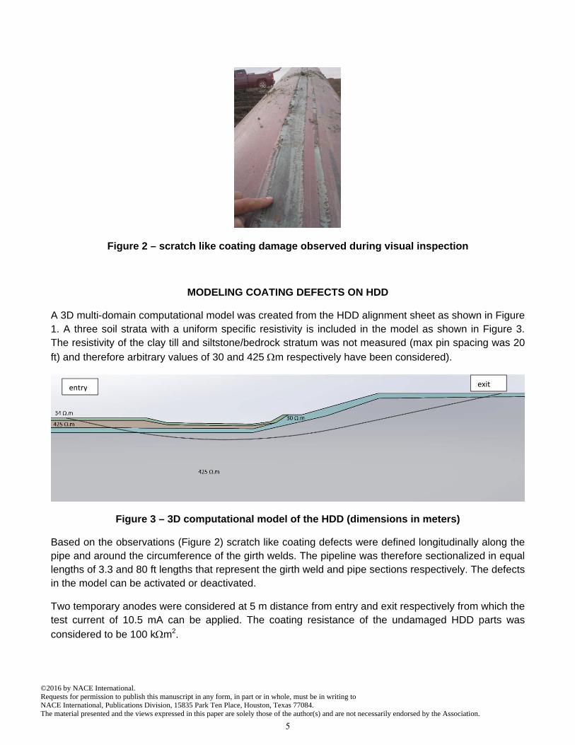
Figure 2 – scratch like coating damage observed during visual inspection
MODELING COATING DEFECTS ON HDD
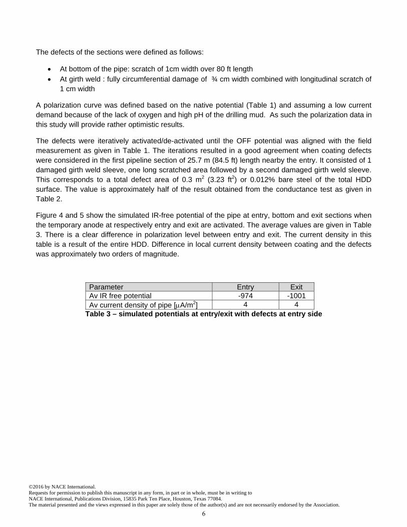
A 3D multi-domain computational model was created from the HDD alignment sheet as shown in Figure 1. A three soil strata with a uniform specific resistivity is included in the model as shown in Figure 3. The resistivity of the clay till and siltstone/bedrock stratum was not measured (max pin spacing was 20
ft) and therefore arbitrary values of 30 and 425 m respectively have been considered).
Figure 3 – 3D computational model of the HDD (dimensions in meters)
Based on the observations (Figure 2) scratch like coating defects were defined longitudinally along the pipe and around the circumference of the girth welds. The pipeline was therefore sectionalized in equal lengths of 3.3 and 80 ft lengths that represent the girth weld and pipe sections respectively. The defects in the model can be activated or deactivated.
Two temporary anodes were considered at 5 m distance from entry and exit respectively from which the test current of 10.5 mA can be applied. The coating resistance of the undamaged HDD parts was
considered to be 100 km2.
entry exit
5
©2016 by NACE International.Requests for permission to publish this manuscript in any form, in part or in whole, must be in writing toNACE International, Publications Division, 15835 Park Ten Place, Houston, Texas 77084.The material presented and the views expressed in this paper are solely those of the author(s) and are not necessarily endorsed by the Association.
The defects of the sections were defined as follows:
At bottom of the pipe: scratch of 1cm width over 80 ft length At girth weld : fully circumferential damage of ¾ cm width combined with longitudinal scratch of
1 cm width
A polarization curve was defined based on the native potential (Table 1) and assuming a low current demand because of the lack of oxygen and high pH of the drilling mud. As such the polarization data in this study will provide rather optimistic results.
The defects were iteratively activated/de-activated until the OFF potential was aligned with the field measurement as given in Table 1. The iterations resulted in a good agreement when coating defects were considered in the first pipeline section of 25.7 m (84.5 ft) length nearby the entry. It consisted of 1 damaged girth weld sleeve, one long scratched area followed by a second damaged girth weld sleeve. This corresponds to a total defect area of 0.3 m2 (3.23 ft2) or 0.012% bare steel of the total HDD surface. The value is approximately half of the result obtained from the conductance test as given in Table 2.
Figure 4 and 5 show the simulated IR-free potential of the pipe at entry, bottom and exit sections when the temporary anode at respectively entry and exit are activated. The average values are given in Table 3. There is a clear difference in polarization level between entry and exit. The current density in this table is a result of the entire HDD. Difference in local current density between coating and the defects was approximately two orders of magnitude.
Parameter Entry Exit Av IR free potential -974 -1001 Av current density of pipe [A/m2] 4 4
Table 3 – simulated potentials at entry/exit with defects at entry side
6
©2016 by NACE International.Requests for permission to publish this manuscript in any form, in part or in whole, must be in writing toNACE International, Publications Division, 15835 Park Ten Place, Houston, Texas 77084.The material presented and the views expressed in this paper are solely those of the author(s) and are not necessarily endorsed by the Association.

Figure 4 – IR free potentials on pipe with activated anode and defects at entry side
7
©2016 by NACE International.Requests for permission to publish this manuscript in any form, in part or in whole, must be in writing toNACE International, Publications Division, 15835 Park Ten Place, Houston, Texas 77084.The material presented and the views expressed in this paper are solely those of the author(s) and are not necessarily endorsed by the Association.

Figure 5 – IR free potentials on pipe with activated anode at exit side and defects at entry side
The scenario was again simulated for similar defects except being situated at the lowest point of the HDD. The coating at the entry and exit were considered to be intact while at the deepest point of the HDD, damage at two girth welds and one section with a longitudinal scratch was activated. Table 4 outlines the results of the IR-free potential when the anode entry and exit side have been activated respectively. Note that in this case there is no clear difference in potential value between entry and exit. This indicates that the HDD is well polarizable at the extremities but no information could be obtained from the lowest point. As can be seen in Figure 6 the deepest point of the HDD has more electro-positive potentials reaching a value of -936mV at the girth welds. Note also that the average current density on the pipe is the same as in previous case.
8
©2016 by NACE International.Requests for permission to publish this manuscript in any form, in part or in whole, must be in writing toNACE International, Publications Division, 15835 Park Ten Place, Houston, Texas 77084.The material presented and the views expressed in this paper are solely those of the author(s) and are not necessarily endorsed by the Association.

Parameter Entry Exit Av IR free (OFF) potential -1036 -1035 Av current density of pipe [A/m2] 4 4
Table 4 – simulated potentials at entry/exit with defects at lowest point
Figure 6 – IR free potentials on pipe with activated anode at entry side and defects at lowest point
9
©2016 by NACE International.Requests for permission to publish this manuscript in any form, in part or in whole, must be in writing toNACE International, Publications Division, 15835 Park Ten Place, Houston, Texas 77084.The material presented and the views expressed in this paper are solely those of the author(s) and are not necessarily endorsed by the Association.

Figure 7 – IR free potentials on pipe with activated anode at exit side and defects at lowest point
Details of the IR-free protection potential at the coating defects are shown in Figures 8 for respectively the longitudinal scratch and the circumferential and longitudinal scratch at the weld. The results of the protection level of the defects are summarized in Table 5.
Parameter Longitudinal scratch
Long+circum. scratch
Min IR-free potential of defect [mV] -870 -853 Max current density of defect [mA/m2] 23 16 Av IR free potential of pipe section [mV] -958 -949 Av current density of pipe [A/m2] 4 4
Table 5 – simulated potentials and current density with damaged coating at deepest point
10
©2016 by NACE International.Requests for permission to publish this manuscript in any form, in part or in whole, must be in writing toNACE International, Publications Division, 15835 Park Ten Place, Houston, Texas 77084.The material presented and the views expressed in this paper are solely those of the author(s) and are not necessarily endorsed by the Association.

Figure 8 – details of the IR free potential at the coating defects (top: longitudinal scratch
between girth welds, bottom: circumferential and longitudinal scratch at girth welds)
11
©2016 by NACE International.Requests for permission to publish this manuscript in any form, in part or in whole, must be in writing toNACE International, Publications Division, 15835 Park Ten Place, Houston, Texas 77084.The material presented and the views expressed in this paper are solely those of the author(s) and are not necessarily endorsed by the Association.

DISCUSSION
There is a large discrepancy of the calculated % bare steel obtained by the conductance test and the current requirement methods. The conductance test method overestimates the % of bare steel while the current requirement method underestimates this value. The result of both tests depends on the current demand of the coating and of the defects, and on the soil resistivity. In the case of large defects with a low current demand, the HDD will be easily polarized and thus the % of bare steel will be underestimated. The imposed current will be low and the difference between ON and OFF potential is rather small. Moreover in the case of the conductance test the position of the reference electrodes plays a role as well. They are generally installed at the extremities and will mainly measure the behavior of the HDD in the line-of-sight. This was clearly demonstrated through simulations since there was no difference between entry and exit when the defects at the lowest point (approx. in middle of HDD) have been activated.
Normalized coating
conductance
Current density for 100mV shift
Simulations
% bare steel 0.037% 0.002% 0.012% Min potential -966 mV n.a -853
The simulations indicate that the protection level of the coating defects are 80 to 100mV less polarized than undamaged areas. In this particular case, the polarization shift observed at defects situated in the extremities of the HDD was only 28 to 45mV from the native pipe potential (Table 1). A potential shift of 100mV at the defects is thus not achieved. The protection level would even be lower if a higher current demand was considered along with accounting for areas of undamaged coating also consuming a
portion of available current. It was determined that the high quality dual FBE coating (R=100m2) coated portion of the HDD drained approx. 20% of imposed current (2 of the 10.5mA). In order to design a proper CP system, the current required by the HDD must be 4 times higher to achieve a 100mV shift. Therefore an initial application current of 42mA is required with an additional 20% to account for the current consumed by the coated region. Based on the field test methods however the current requirement was calculated as 14 mA (7.7 at entry and 6.3 mA at exit) only, underestimating the actual current demand of the defects.
CONCLUSIONS
Although the field coating conductance and current requirement tests do provide some indication on the average bare steel percentage; information on the amount, size, location and polarization level of the coating defects is not available. As such, it is difficult to validate the CP effectiveness for critical, inaccessible regions of the HDD’s and design an effective functioning CP system. Through computational modeling it was demonstrated that for particular cases with longitudinal scratches and damaged girth weld sleeves, the CP current requirement can accurately be measured for defects at the most critical point (bottom of the HDD). Using this technology, more challenging situations such as HDD’s crossing a rock layer can be investigated and can bring more clarity on the effectiveness of cathodic protection throughout the bore.
12
©2016 by NACE International.Requests for permission to publish this manuscript in any form, in part or in whole, must be in writing toNACE International, Publications Division, 15835 Park Ten Place, Houston, Texas 77084.The material presented and the views expressed in this paper are solely those of the author(s) and are not necessarily endorsed by the Association.

ACKNOWLEDGEMENTS
The authors would like to recognize and sincerely thank Enbridge Pipelines’ Mike Hill, Yvan Hubert, Kurt Baraniecki and Walter Kresic for their continual support, dedication and devotion towards advancing pipeline integrity management.
REFERENCES
1‐ ANSI/NACE; SP0502. (2008). Standard Practice ‐ Pipeline External Corrrosion Direct Assessment Methodology.
Houston, TX: ANSI (American National Standards Institute) / NACE International.
2‐ NACE; SP0169. (2013). Standard Practice ‐ Control of External Corrosion on Underground or Submerged
Metallic Piping Systems. Houston, TX: NACE International.
3‐ R.A. Gummow, W. F. (2012). Would the Real ‐850 mVCSE Criterion Please Stand Up. Corrosion 2012; Paper
No. C2012‐0001347. Salt Lake City, UT: NACE International.
4‐ NACE TM0497. (2012). Standard Test Method ‐ Measurement Techniques Related to Criteria for Cathodic
Protection on Underground or Submerged Metallic Piping Systems. Houston, TX: NACE International.
5‐ CORTEST Columbus Technologies, Inc. (October 29, 1993). Multiple Pipelines In Right‐Of‐Way: Improved Pipe‐
To‐Soil Potential Survey Methods. Houston: PRCI Catalog No. L51692e; Contract # PR‐186‐9105.
6‐ ANSI / NACE Standard RP0104. (2004). Standard Recommended Practice ‐ The Use of Coupons for Cathodic
Protection Monitoring Applications; Item No. 21105. Houston, TX: ANSI (American National Standards
Institute) / NACE International.
7‐ IEEE Standard 81. (2012). Guide for Measuring Earth Resistivity, Ground Impedance, and Earth Surface
Potentials of a Ground System. New York, NY: Institute of Electrical and Electronics Engineers, Inc. (IEEE).
8‐ D.Janda, C. B. (2013). A New Approach to Pipeline Integrity – Combining In‐Line Inspection and Cathodic
Protection Simulation Technology. CORROSION 2013, Paper No. 2239 (p. 5). Orlando, FL: NACE.
9‐ Corrosion Service Company Limited (CSCL). (August 2015). PR‐444‐133602 : Evaluation of Current Practices
and Equipment Used for Assessing the Integrity of Coating Systems on Pipelines Installed in Trenchless
Crossings. Houston: Pipeline Research Council International (PRCI).
10 ‐ NACE; TM0102. (2002). Measurement of Protective Coating Electrical Conductance on Underground
Pipelines . Houston, TX: NACE International.
13
©2016 by NACE International.Requests for permission to publish this manuscript in any form, in part or in whole, must be in writing toNACE International, Publications Division, 15835 Park Ten Place, Houston, Texas 77084.The material presented and the views expressed in this paper are solely those of the author(s) and are not necessarily endorsed by the Association.


![Untitled-1 [] · Nimbu Masti Mix Tasty t Bhujia Bhujia h atta Meet . Bøondi . RUSK](https://static.fdocuments.in/doc/165x107/5b0262a57f8b9a6a2e8fb613/untitled-1-masti-mix-tasty-t-bhujia-bhujia-h-atta-meet-bondi-rusk.jpg)