
Paper 12- Improvement of Sacrificial Anode Life for Internal Surface of Process Vessels in Upstr
27
Improvement Of Sacrificial Anode Life For Internal Surface Of Process Vessels In Upstream of Oil & Gas Facilities www.kockw.com Saleh Al-Sulaiman Hasan Sabri Mohammed Abdul-Fatah Eugene D’souza (Presenter) Inspection and Corrosion Team, Kuwait Oil Company
description
internal cp for vessels
Transcript of Paper 12- Improvement of Sacrificial Anode Life for Internal Surface of Process Vessels in Upstr
Improvement Of Sacrificial Anode Life For
Internal Surface Of Process Vessels
In Upstream of
Oil & Gas Facilities
www.kockw.com
Saleh Al-Sulaiman
Hasan Sabri
Mohammed Abdul-Fatah
Eugene D’souza (Presenter)
Inspection and Corrosion Team,
Kuwait Oil Company

2
Presentation Overview
Introduction
Gathering Center Process Overview
Types Of Separators
Separator Construction and Operational Details
Comparison between Separators
Case Study
Results
Conclusions
3
The Kuwait Oil Company is one of the major oil producing
companies in the world.
Company mainly executes exploration, drilling, and
extraction of oil and gas within the State of Kuwait.
Oil produced from several oil fields including Burgan,
Ahmadi and Magwa.
Operates 21 Gathering Centers and 4 Booster Stations.
Introduction
4
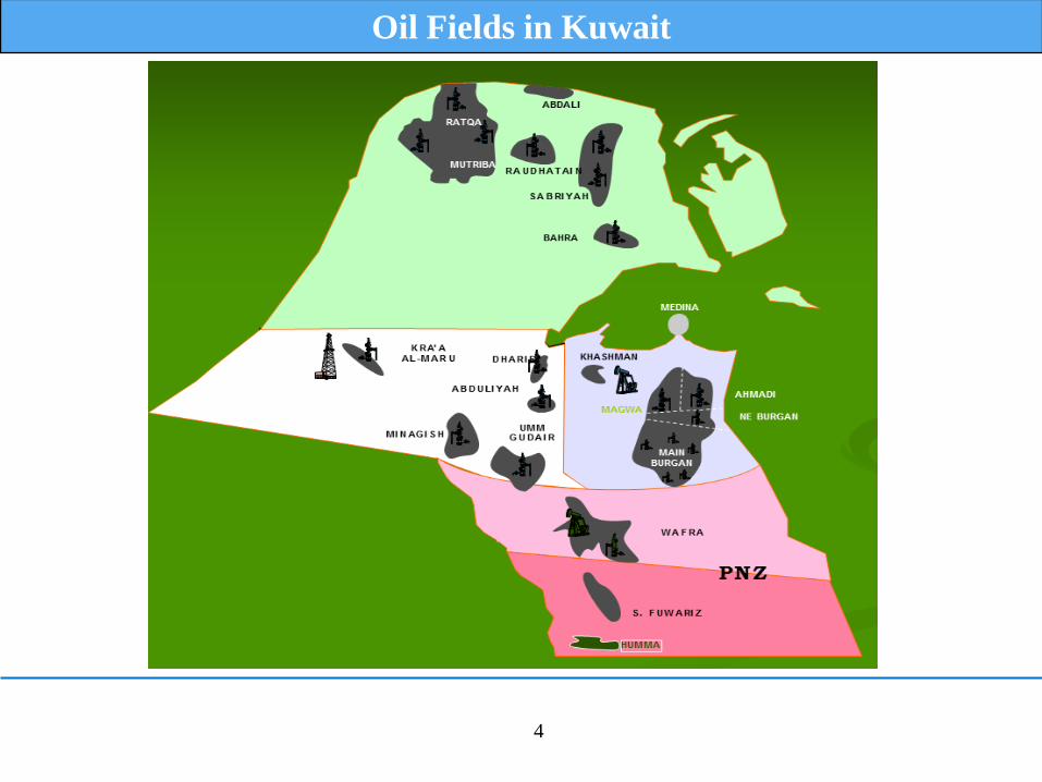
Oil Fields in Kuwait

5
Gathering Center Satellite Image
6
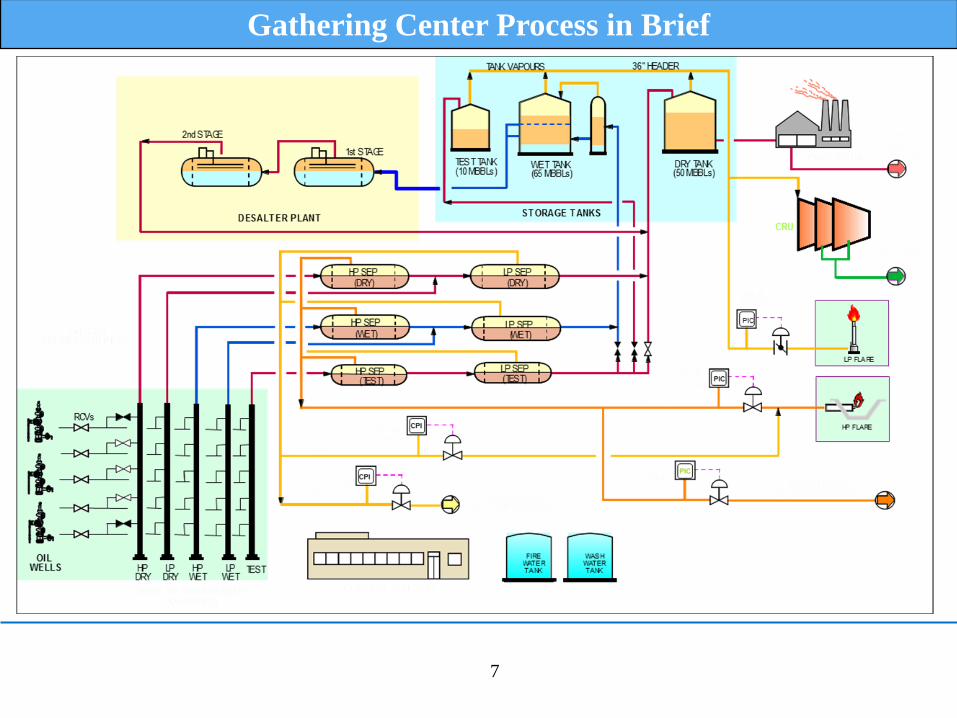
Serves as a collection (Gathering) location of Crude Oil from wells
Separates the Crude Oil, Gas and Water.
Facilitates Oil Wells Testing
Provides intermediate storage for the Crude Oil prior to pumping to
the Tank Farms
Compresses Tank vapors for condensate recovery
Transports the gas for further compression at the Booster Stations.
Gathering Center (GC)
7
Gathering Center Process in Brief
8
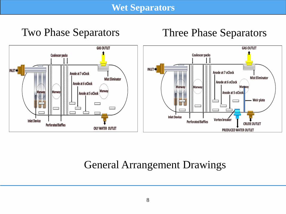
Wet Separators
Two Phase Separators Three Phase Separators
General Arrangement Drawings
9
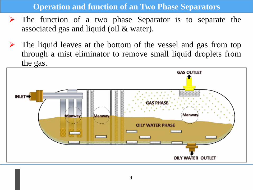
Operation and function of an Two Phase Separators
The function of a two phase Separator is to separate the associated gas and liquid (oil & water).
The liquid leaves at the bottom of the vessel and gas from top through a mist eliminator to remove small liquid droplets from the gas.
10
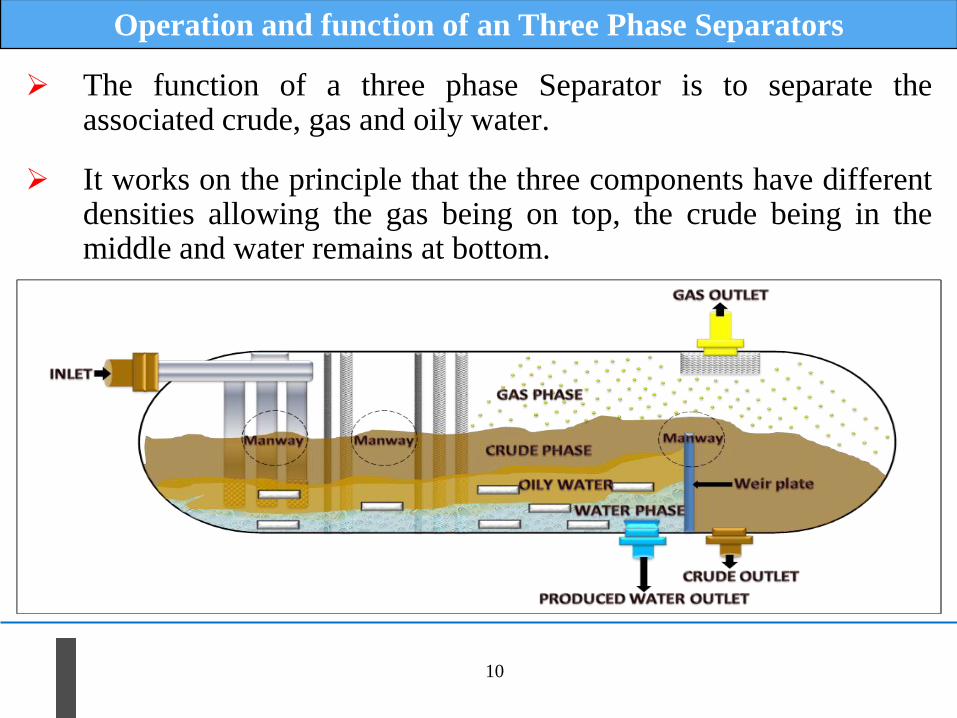
Operation and function of an Three Phase Separators
The function of a three phase Separator is to separate the associated crude, gas and oily water.
It works on the principle that the three components have different densities allowing the gas being on top, the crude being in the middle and water remains at bottom.
11
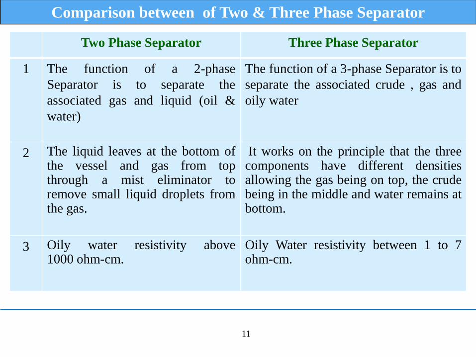
Comparison between of Two & Three Phase Separator
Two Phase Separator Three Phase Separator
1 The function of a 2-phase
Separator is to separate the
associated gas and liquid (oil &
water)
The function of a 3-phase Separator is to
separate the associated crude , gas and
oily water
2 The liquid leaves at the bottom of the vessel and gas from top through a mist eliminator to remove small liquid droplets from the gas.
It works on the principle that the three components have different densities allowing the gas being on top, the crude being in the middle and water remains at bottom.
3 Oily water resistivity above 1000 ohm-cm.
Oily Water resistivity between 1 to 7 ohm-cm.
12
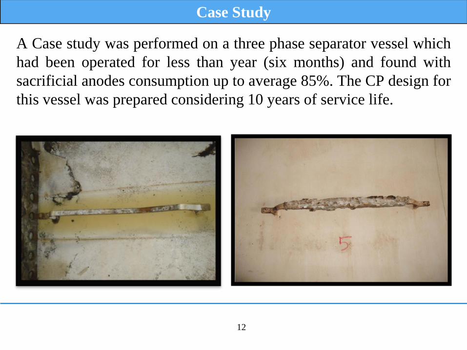
A Case study was performed on a three phase separator vessel which
had been operated for less than year (six months) and found with
sacrificial anodes consumption up to average 85%. The CP design for
this vessel was prepared considering 10 years of service life.
Case Study
13
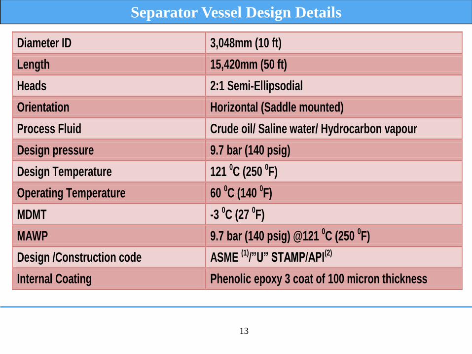
Separator Vessel Design Details
Diameter ID 3,048mm (10 ft)
Length 15,420mm (50 ft)
Heads 2:1 Semi-Ellipsodial
Orientation Horizontal (Saddle mounted)
Process Fluid Crude oil/ Saline water/ Hydrocarbon vapour
Design pressure 9.7 bar (140 psig)
Design Temperature 121 0C (250 0F)
Operating Temperature 60 0C (140 0F)
MDMT -3 0C (27 0F)
MAWP 9.7 bar (140 psig) @121 0C (250 0F)
Design /Construction code ASME (1)/”U” STAMP/API(2)
Internal Coating Phenolic epoxy 3 coat of 100 micron thickness

14
Vessel Material Specifications and Internal structure details
Shell (Material/thickness) SA 516 Gr.60N / 18mm UNS K02100
Heads (Material/thickness)
SA 516 Gr.60N / 20mm (nominal) 16.5 (minimum)
UNS K02100
Nozzles SA 106 Gr.B UNS K03006
Flange SA 105N UNS K03504
Nut and Bolts SA193 B8M/SA194 8M SS parts SA193 B7M/SA194 7M CS parts
UNS S31254 SS parts UNS G41400 CS parts
Inlet momentum absorber Inlet device/316L stainless steel UNS S31603
Baffle(s) 2 x Perforated Baffles/316L stainless steel UNS S31603
Coalescer pack(s) 3 x Demisters /316L stainless steel UNS S31603
Mist eliminator 316L Stainless Steel UNS S31603
Vortex breaker(s) Oil & water outlet/SA 516 Gr 60N / Epoxy coated
UNS K02100
Weir plate Carbon steel/ Epoxy Coated UNS K02100
Sludge wash header(s) Carbon steel/ Epoxy coated UNS K02100
Sacrificial anodes Aluminum Alloy -
15
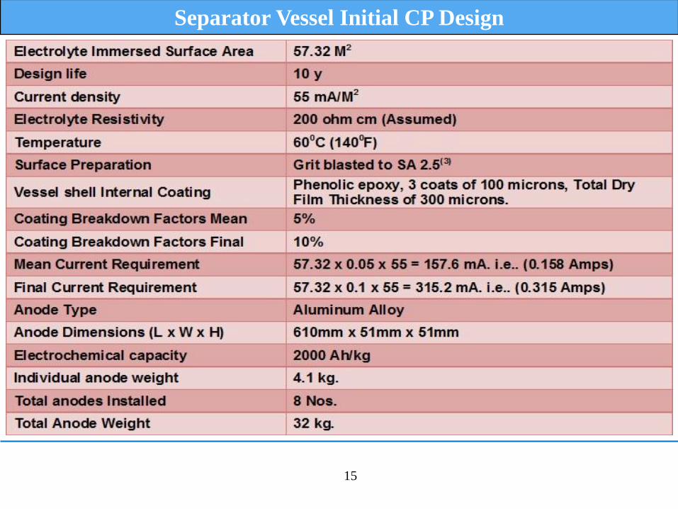
Separator Vessel Initial CP Design
16
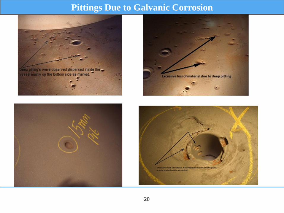
Observations & Findings
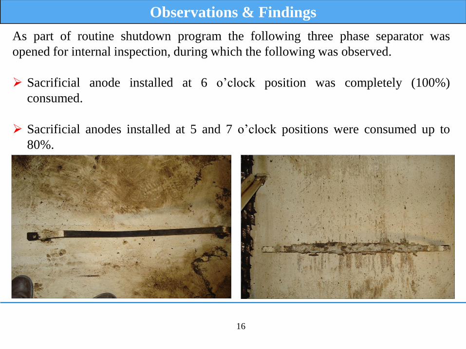
As part of routine shutdown program the following three phase separator was
opened for internal inspection, during which the following was observed.
Sacrificial anode installed at 6 o’clock position was completely (100%)
consumed.
Sacrificial anodes installed at 5 and 7 o’clock positions were consumed up to
80%.
17
Observations & Findings
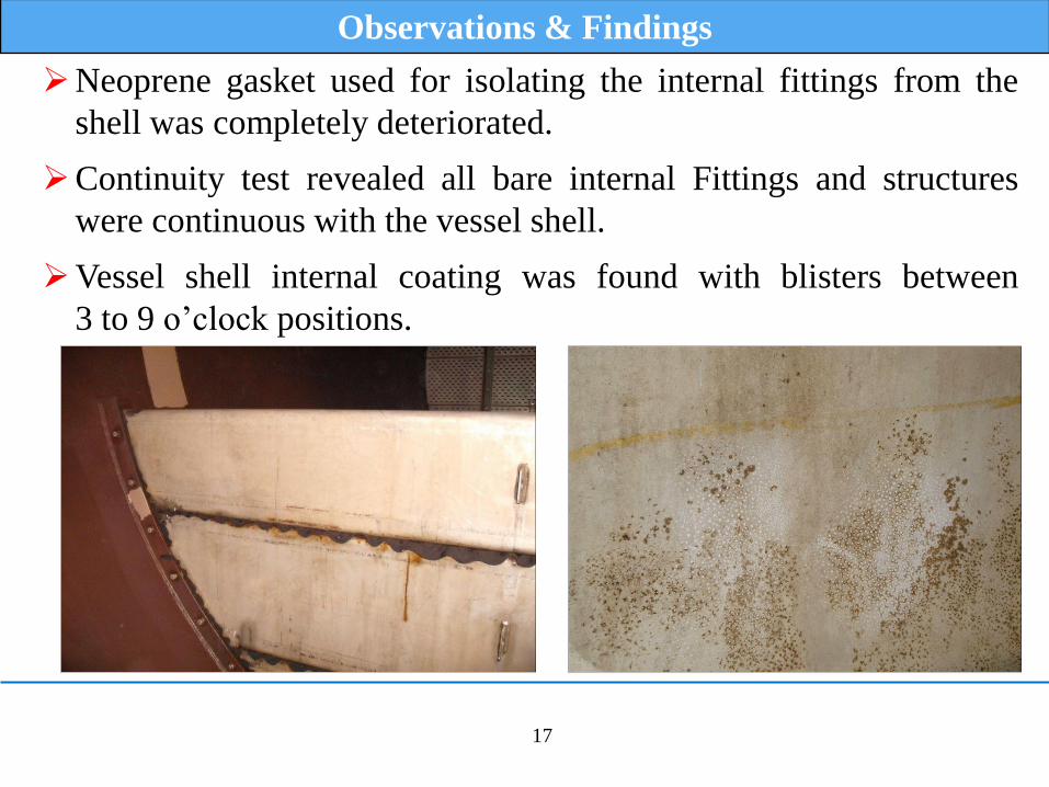
Neoprene gasket used for isolating the internal fittings from the
shell was completely deteriorated.
Continuity test revealed all bare internal Fittings and structures
were continuous with the vessel shell.
Vessel shell internal coating was found with blisters between
3 to 9 o’clock positions.
18
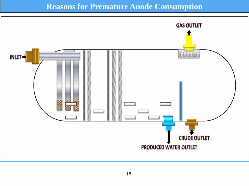
Reasons for Premature Anode Consumption
19
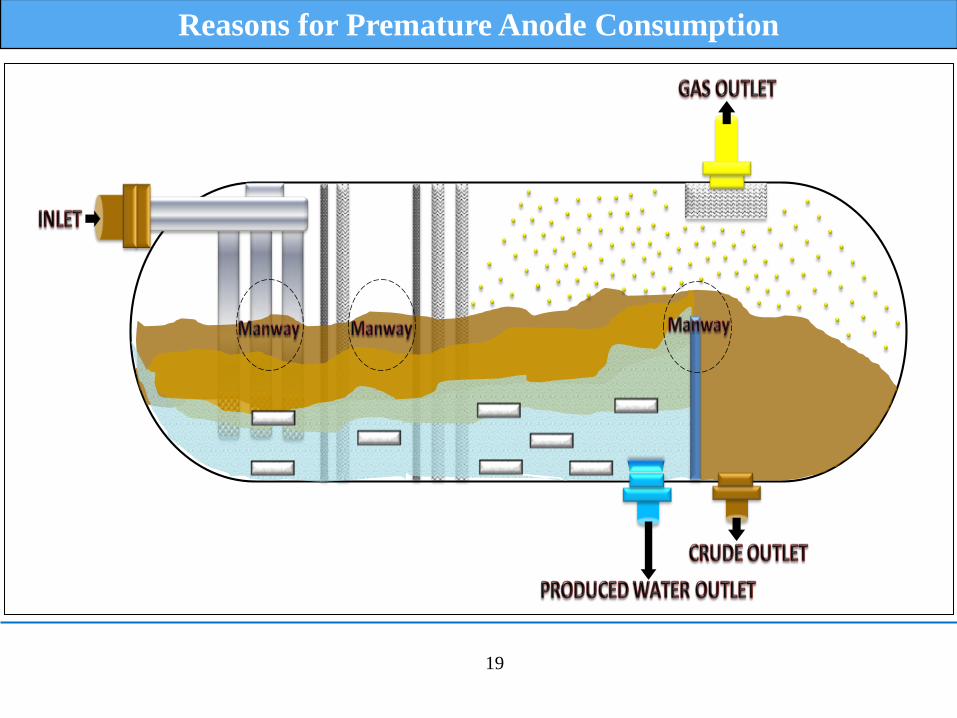
Reasons for Premature Anode Consumption
20
Pittings Due to Galvanic Corrosion
21
Alternative Approach
Based on the observations and findings and as part of a
remedial action the following plan was implemented.
New CP design considering actual vessel operating
conditions.
Painting of vessel shell internal between 3 to 9 o’clock
positions.
Painting of all internal structures and fittings.
Change of isolating materials from Neoprene gasket to Poly
Tetra Fluoro Ethylene (PTFE) based upon compatibility with
service environment.
22
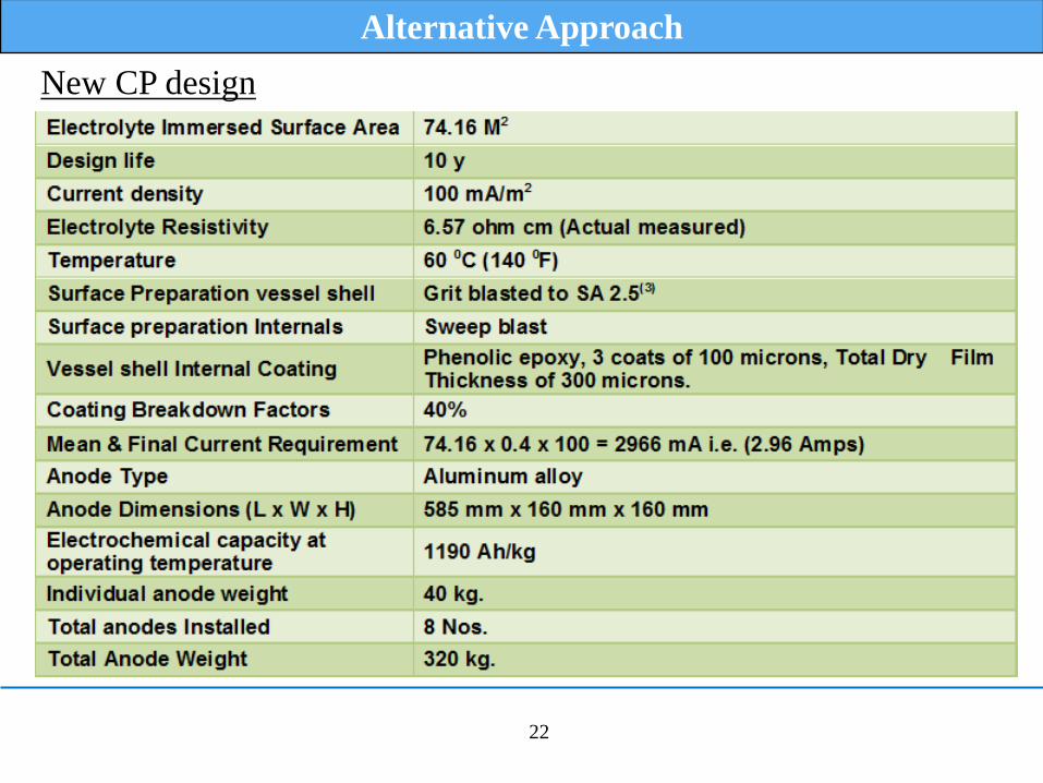
Alternative Approach
New CP design
23
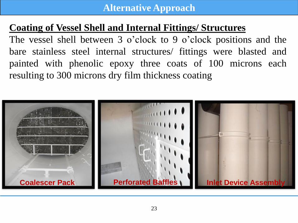
Alternative Approach
Coating of Vessel Shell and Internal Fittings/ Structures
The vessel shell between 3 o’clock to 9 o’clock positions and the
bare stainless steel internal structures/ fittings were blasted and
painted with phenolic epoxy three coats of 100 microns each
resulting to 300 microns dry film thickness coating
Coalescer Pack Perforated Baffles Inlet Device Assembly
24
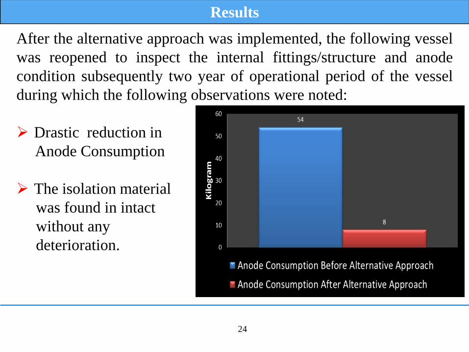
Results
After the alternative approach was implemented, the following vessel
was reopened to inspect the internal fittings/structure and anode
condition subsequently two year of operational period of the vessel
during which the following observations were noted:
Drastic reduction in
Anode Consumption
The isolation material
was found in intact
without any
deterioration.
25
Conclusion
Conclusion are based on the actual observation and finding mentioned
above. It is evident that the initial Cathodic Protection design and
construction practice required modifications to enhance the life of the
cathodic protection and below are the modifications:
Cathodic Protection Design Considerations
Surface Area considered in the design shall include immersed sections
of vessel shell and internal fittings/structures.
Electrolyte resistivity used for design purpose shall be physically
measured.
Operational temperature of the vessel shall be considered to derive the
actual required current density and to derate the anode electrochemical
capacity.
continued….
26
Conclusion
Coating and Isolation Considerations
Application of coating the bare internal fittings/ structures regardless
of its material specifications could reduce the current requirement
drastically in situation of failures in isolation.
The isolating gasket material used to isolate the internal fittings from
the vessel shell shall be compatible with the service environment.
For internal structures where coating is impractical, positive isolation
shall be achieved by isolation gasket or by increasing the coating
thickness at contact locations between vessel and structure.
After implementation of alternative approach the anode consumption
reduced from 54.5 kg per year to 8 kg per year i.e. saving 85.3% of
anode weight per year, resulting in increased anode life.

Sample Chart
27
Thank You